- Table of Contents
- Related Documents
-
| Title | Size | Download |
|---|---|---|
| 01-VXLAN configuration | 1.06 MB |
Assignment of traffic to VXLANs
Configuring basic VXLAN features
Setting the VXLAN hardware resource mode
Configuration restrictions and guidelines
Configuration restrictions and guidelines
Assigning VXLAN tunnels to a VXLAN
Assigning customer frames to a VSI
Configuration restrictions and guidelines
Mapping a static Ethernet service instance to a VSI
Mapping dynamic Ethernet service instances to VSIs
Configuring VLAN-based VXLAN assignment
Configuration restrictions and guidelines
Configuring static MAC address entries
Disabling local-MAC address learning
Disabling remote-MAC address learning
Setting the MAC learning priority of an Ethernet service instance
Enabling local-MAC change logging
Enabling software-based MAC learning on an interface
Configuring a multicast-mode VXLAN
Configuring a VTEP using the PIM method
Configuring a VTEP using the IGMP host method
Confining floods to the local site
Setting the destination UDP port number of VXLAN packets
Configuring VXLAN packet check
Enabling default VXLAN decapsulation
Enabling ARP flood suppression
Disabling remote ARP or ND learning for VXLANs
Enabling VXLAN packet statistics
Enabling packet statistics for a VSI
Enabling packet statistics for Ethernet service instances
Enabling packet statistics for VXLAN tunnels
Testing the reachability of a remote VM
Displaying and maintaining VXLANs
Unicast-mode VXLAN configuration example
Multicast-mode VXLAN configuration example
VXLAN IP gateways separated from VTEPs
Centralized VXLAN IP gateway deployment
Centralized VXLAN gateway group deployment
Distributed VXLAN IP gateway deployment
Feature and hardware compatibility
Configuration restrictions and guidelines
Configuring a centralized VXLAN IP gateway
Configuring a centralized VXLAN IP gateway group
Configuration restrictions and guidelines
Specifying a VTEP group as the gateway for an access layer VTEP
Configuring a distributed VXLAN IP gateway
Configuration restrictions and guidelines
Enabling packet statistics for a VSI interface
Displaying and maintaining VXLAN IP gateway
VXLAN IP gateway configuration examples
Centralized VXLAN IP gateway configuration example
Centralized VXLAN IP gateway group configuration example
Distributed VXLAN IPv4 gateway configuration example
Distributed VXLAN IPv6 gateway configuration example
Feature and hardware compatibility
VXLAN-DCI configuration task list
Configuring a VXLAN-DCI tunnel
Assigning a VXLAN-DCI tunnel to a VXLAN
Specifying a gateway interface for a VSI
Enabling packet statistics for manually created VXLAN-DCI tunnels
Displaying and maintaining VXLAN-DCI
VXLAN-DCI configuration example
Configuring the VTEP as an OVSDB VTEP
OVSDB VTEP configuration task list
Setting up an OVSDB connection to a controller
Configuration restrictions and guidelines
Configuring active SSL connection settings
Configuring passive SSL connection settings
Configuring active TCP connection settings
Configuring passive TCP connection settings
Enabling the OVSDB VTEP service
Specifying a global source address for VXLAN tunnels
Enabling flood proxy on multicast VXLAN tunnels
OVSDB VTEP configuration examples
Unicast-mode VXLAN configuration example
Flood proxy VXLAN configuration example
VXLAN overview
Virtual eXtensible LAN (VXLAN) is a MAC-in-UDP technology that provides Layer 2 connectivity between distant network sites across an IP network. VXLAN is typically used in data centers for multitenant services.
VXLAN provides the following benefits:
· Support for more virtual switched domains than VLANs—Each VXLAN is uniquely identified by a 24-bit VXLAN ID. The total number of VXLANs can reach 16777216 (224). This specification makes VXLAN a better choice than 802.1Q VLAN to isolate traffic for VMs.
· Easy deployment and maintenance—VXLAN requires deployment only on the edge devices of the transport network. Devices in the transport network perform typical Layer 3 forwarding.
The device supports only IPv4-based VXLAN. IPv6-based VXLAN is not supported.
VXLAN network model
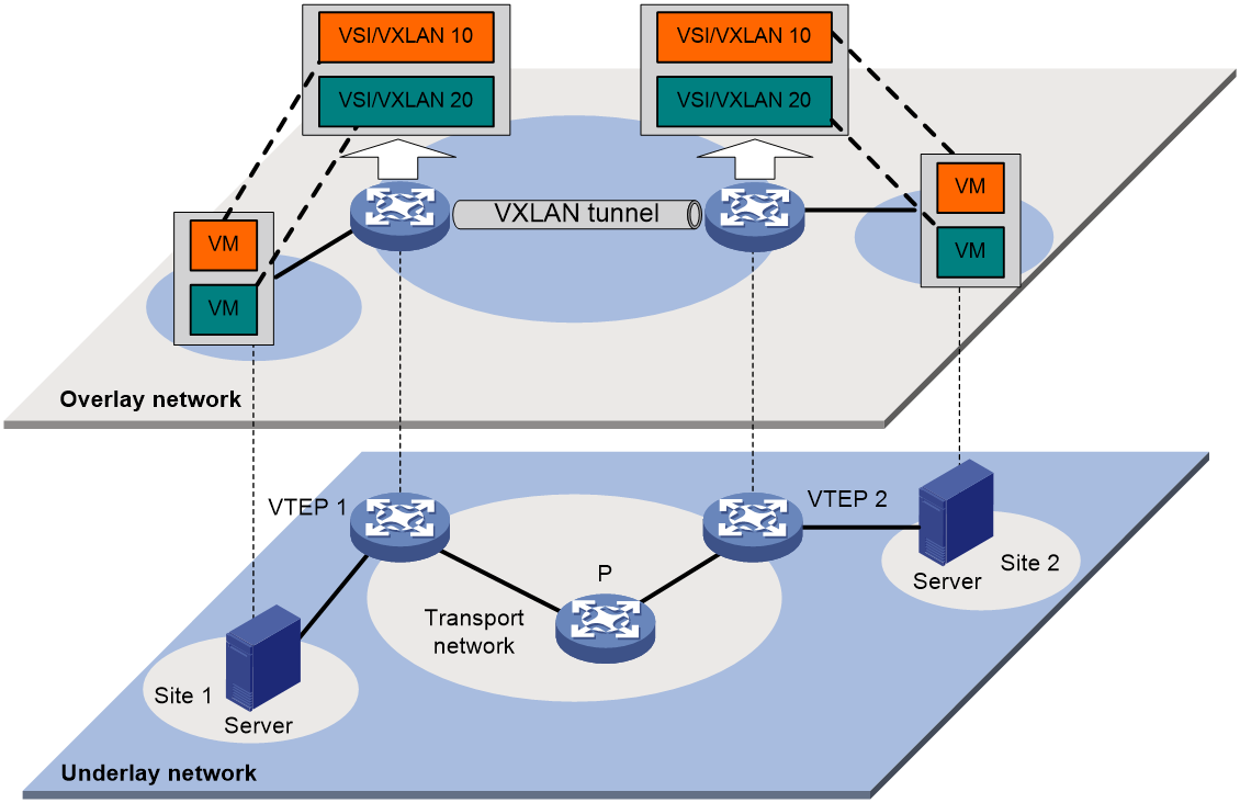
As shown in Figure 1, a VXLAN is a virtual Layer 2 network (known as the overlay network) built on top of an existing physical Layer 3 network (known as the underlay network). The overlay network encapsulates inter-site Layer 2 frames into VXLAN packets and forwards the packets to the destination along the Layer 3 forwarding paths provided by the underlay network. The underlay network is transparent to tenants, and geographically dispersed sites of a tenant are merged into a Layer 2 network.
The transport edge devices assign VMs to different VXLANs, and then forward traffic between sites for VMs by using VXLAN tunnels.
The transport edge devices are VXLAN tunnel endpoints (VTEP). They can be servers that host VMs or independent network devices.
An H3C VTEP uses VSIs and VXLAN tunnels to provide VXLAN services.
· VSI—A virtual switch instance is a virtual Layer 2 switched domain. Each VSI provides switching services only for one VXLAN. VSIs learn MAC addresses and forward frames independently of one another. VMs in different sites have Layer 2 connectivity if they are in the same VXLAN.
· VXLAN tunnel—Logical point-to-point tunnels between VTEPs over the transport network. Each VXLAN tunnel can trunk multiple VXLANs.
VTEPs encapsulate VXLAN traffic in the VXLAN, outer UDP, and outer IP headers. The devices in the transport network forward VXLAN traffic only based on the outer IP header.
Figure 1 VXLAN network model
VXLAN packet format
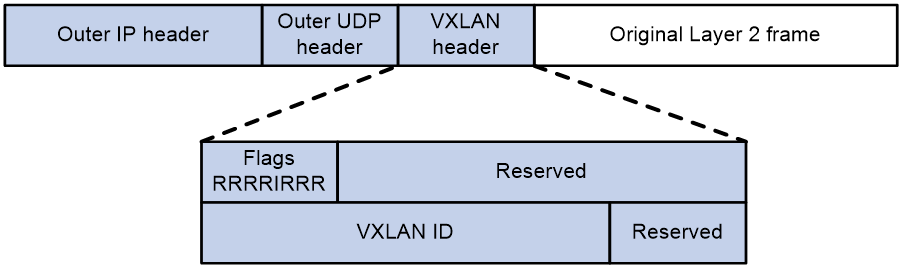
As shown in Figure 2, a VTEP encapsulates a frame in the following headers:
· 8-byte VXLAN header—VXLAN information for the frame.
¡ Flags—If the I bit is 1, the VXLAN ID is valid. If the I bit is 0, the VXLAN ID is invalid. All other bits are reserved and set to 0.
¡ 24-bit VXLAN ID—Identifies the VXLAN of the frame. It is also called the virtual network identifier (VNI).
· 8-byte outer UDP header for VXLAN—The default VXLAN destination UDP port number is 4789.
· 20-byte outer IP header—Valid addresses of VTEPs or VXLAN multicast groups on the transport network. Devices in the transport network forward VXLAN packets based on the outer IP header.
Figure 2 VXLAN packet format
Working mechanisms
The VTEP uses the following process to forward an inter-site frame:
1. Assigns the frame to its matching VXLAN if the frame is sent between sites.
2. Performs MAC learning on the VXLAN's VSI.
3. Forwards the frame through VXLAN tunnels.
This section describes this process in detail. For intra-site frames in a VSI, the system performs typical Layer 2 forwarding, and it processes 802.1Q VLAN tags as described in "Access modes of VSIs."
Assignment of traffic to VXLANs
Traffic from the local site to a remote site
The VTEP uses the following methods to assign customer frames to a VXLAN:
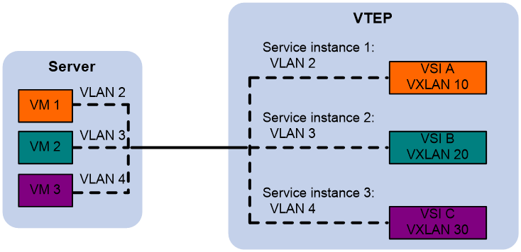
· Ethernet service instance-to-VSI mapping—This method uses the frame match criterion of an Ethernet service instance to match a list of VLANs on a site-facing Layer 2 interface. The frame match criterion specifies the characteristics of traffic from the VLANs, such as tagging status and VLAN IDs. The VTEP assigns customer traffic to a VXLAN by mapping the Ethernet service instance to a VSI.
· VLAN-based VXLAN assignment—This method maps a VLAN to a VXLAN. The VTEP assigns all frames of the VLAN to the VXLAN.
An Ethernet service instance is identical to an attachment circuit (AC) in L2VPN.
As shown in Figure 3, Ethernet service instance 1 matches VLAN 2 and is mapped to VSI A (VXLAN 10). When a frame from VLAN 2 arrives, the VTEP assigns the frame to VXLAN 10, and looks up VSI A's MAC address table for the outgoing interface.
Figure 3 Identifying traffic from the local site
Traffic from a remote site to the local site
When a frame arrives at a VXLAN tunnel, the VTEP uses the VXLAN ID in the frame to identify its VXLAN.
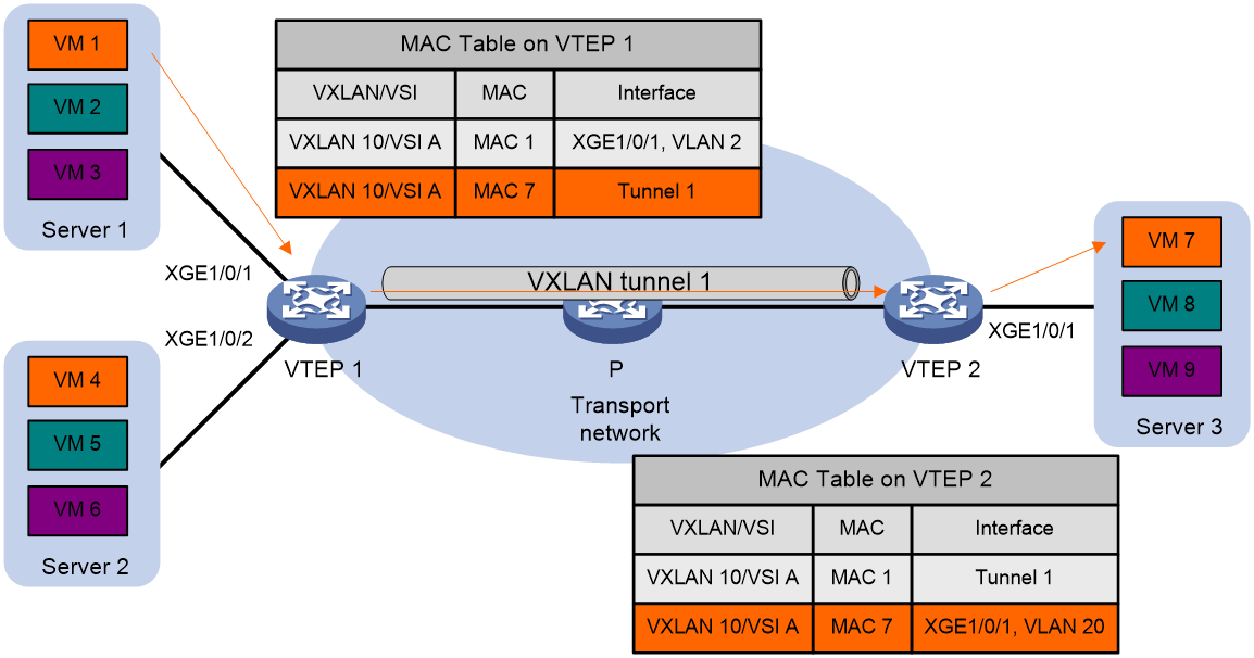
MAC learning
The VTEP performs source MAC learning on the VSI as a Layer 2 switch.
· For traffic from the local site to the remote site, the VTEP learns the source MAC address before VXLAN encapsulation.
· For traffic from the remote site to the local site, the VTEP learns the source MAC address after removing the VXLAN header.
A VSI's MAC address table includes the following types of MAC address entries:
· Local MAC—MAC entries learned from the local site. The outgoing interfaces for the MAC address entries are site-facing interfaces.
¡ Static—Manually added MAC entries.
¡ Dynamic—Dynamically learned MAC entries.
· Remote MAC—MAC entries learned from a remote site. The outgoing interfaces for the MAC address entries are VXLAN tunnel interfaces.
¡ Static—Manually added MAC entries.
¡ Dynamic—MAC entries learned in the data plane from incoming traffic on VXLAN tunnels. The learned MAC addresses are contained in the inner Ethernet header.
¡ OpenFlow—MAC entries issued by a remote controller through OpenFlow.
¡ OVSDB—MAC entries issued by a remote controller through OVSDB.
¡ EVPN—MAC entries advertised through EVPN.
The following shows the priority order of different types of remote MAC address entries:
a. Static MAC address entries, and MAC address entries issued by a remote controller through OpenFlow or OVSDB. These types of entries have the same priority and overwrite each other.
b. MAC address entries advertised through BGP EVPN.
c. Dynamic MAC address entries.
Access modes of VSIs
The access mode of a VSI determines how the VTEP processes the 802.1Q VLAN tags in the Ethernet frames.
VLAN access mode
In this mode, Ethernet frames received from or sent to the local site must contain 802.1Q VLAN tags.
· For an Ethernet frame received from the local site, the VTEP removes all its 802.1Q VLAN tags before forwarding the frame.
· For an Ethernet frame destined for the local site, the VTEP adds 802.1Q VLAN tags to the frame before forwarding the frame.
In this mode, VXLAN packets sent between sites do not contain 802.1Q VLAN tags. You can use different 802.1Q VLANs to provide the same service in different sites.
By default, the access mode of a VSI is VLAN. The following sections describe traffic forwarding processes in VLAN access mode.
Ethernet access mode
The VTEP does not process the 802.1Q VLAN tags of Ethernet frames received from or sent to the local site.
· For an Ethernet frame received from the local site, the VTEP forwards the frame with the 802.1Q VLAN tags intact.
· For an Ethernet frame destined for the local site, the VTEP forwards the frame without adding 802.1Q VLAN tags.
In Ethernet access mode, VXLAN packets sent between VXLAN sites contain 802.1Q VLAN tags. You must use the same VLAN to provide the same service between sites.
Traffic forwarding
A VTEP uses the following processes to forward traffic at Layer 2:
· Unicast process—Applies to destination-known unicast traffic.
· Flood process—Applies to multicast, broadcast, and unknown unicast traffic.
When the VTEP forwards VXLAN traffic, it processes the 802.1Q tag in the inner Ethernet header depending on the VSI access mode (VLAN or Ethernet mode). In VLAN access mode, sites can use different VLANs to provide the same service. For more information, see "Access modes of VSIs."
Unicast
The following process (see Figure 4) applies to a known unicast frame between sites:
1. The source VTEP encapsulates the Ethernet frame in the VXLAN/UDP/IP header.
In the outer IP header, the source IP address is the source VTEP's VXLAN tunnel source IP address. The destination IP address is the VXLAN tunnel destination IP address.
2. The source VTEP forwards the encapsulated packet out of the outgoing VXLAN tunnel interface found in the VSI's MAC address table.
3. The intermediate transport devices (P devices) forward the frame to the destination VTEP by using the outer IP header.
4. The destination VTEP removes the headers on top of the inner Ethernet frame. It then performs MAC address table lookup in the VXLAN's VSI to forward the frame out of the matching outgoing interface.
Flood
The VTEP floods a broadcast, multicast, or unknown unicast frame to all site-facing interfaces and VXLAN tunnels in the VXLAN, except for the incoming interface.
VXLAN supports the following modes for flood traffic:
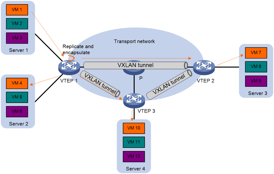
· Unicast mode—Also called head-end replication. The source VTEP replicates the flood frame, and then sends one replica to the destination IP address of each VXLAN tunnel in the VXLAN. See Figure 5.
· Multicast mode—Also called tandem replication. The source VTEP sends the flood frame in a multicast VXLAN packet destined for a multicast group address. Transport network devices replicate and forward the packet to remote VTEPs based on their multicast forwarding entries. See Figure 6.
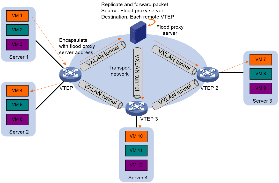
· Flood proxy mode—The source VTEP sends the flood frame in a VXLAN packet over a VXLAN tunnel to a flood proxy server. The flood proxy server replicates and forwards the packet to each remote VTEP through its VXLAN tunnels. See Figure 7.
The flood proxy mode applies to VXLANs that have many sites. This mode reduces flood traffic in the transport network without using a multicast protocol. To use a flood proxy server, you must set up a VXLAN tunnel to the server on each VTEP.
|
|
NOTE: The flood proxy mode is typically used in SDN transport networks that have a flood proxy server. For VTEPs to forward packets based on the MAC address table issued by an SDN controller, you must perform the following tasks on the VTEPs: · Disable remote-MAC address learning by using the vxlan tunnel mac-learning disable command. · Disable source MAC check on all transport-facing interfaces by using the undo mac-address static source-check enable command. If the VTEP is an IRF fabric, you must also disable the feature on all IRF ports. |
Each destination VTEP floods the inner Ethernet frame to all the site-facing interfaces in the VXLAN. To avoid loops, the destination VTEPs do not flood the frame to VXLAN tunnels.

ARP and ND flood suppression
|
|
IMPORTANT: ND flood suppression is available in Release 2612P06 and later. |
ARP or ND flood suppression reduces ARP request broadcasts or ND request multicasts by enabling the VTEP to reply to ARP or ND requests on behalf of VMs.
As shown in Figure 8, this feature snoops ARP or ND packets to populate the ARP or ND flood suppression table with local and remote MAC addresses. If an ARP or ND request has a matching entry, the VTEP replies to the request on behalf of the VM. If no match is found, the VTEP floods the request to both local and remote sites.
Figure 8 ARP flood suppression
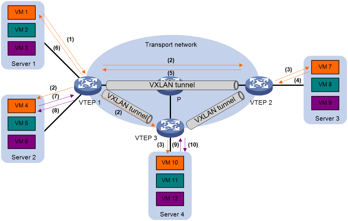
The following uses ARP flood suppression as an example to explain the flood suppression workflow:
1. VM 1 sends an ARP request to obtain the MAC address of VM 7.
2. VTEP 1 creates a suppression entry for VM 1, and floods the ARP request in the VXLAN.
3. VTEP 2 and VTEP 3 de-encapsulate the ARP request. The VTEPs create a suppression entry for VM 1, and broadcast the request in the local site.
4. VM 7 sends an ARP reply.
5. VTEP 2 creates a suppression entry for VM 7 and forwards the ARP reply to VTEP 1.
6. VTEP 1 de-encapsulates the ARP reply, creates a suppression entry for VM 7, and forwards the ARP reply to VM 1.
7. VM 4 sends an ARP request to obtain the MAC address of VM 1 or VM 7.
8. VTEP 1 creates a suppression entry for VM 4 and replies to the ARP request.
9. VM 10 sends an ARP request to obtain the MAC address of VM 1.
10. VTEP 3 creates a suppression entry for VM 10 and replies to the ARP request.
VXLAN IP gateways
A VXLAN IP gateway provides Layer 3 forwarding services for VMs in VXLANs. A VXLAN IP gateway can be an independent device or be collocated with a VTEP. For more information about VXLAN IP gateway placement, see "Configuring VXLAN IP gateways."
Protocols and standards
RFC 7348, Virtual eXtensible Local Area Network (VXLAN): A Framework for Overlaying Virtualized Layer 2 Networks over Layer 3 Networks
Configuring basic VXLAN features
VXLAN configuration task list
|
Tasks at a glance |
Remarks |
|
(Required.) Setting the VXLAN hardware resource mode |
Set the VXLAN hardware resource mode based on the role of the device in the network. |
|
(Required.) Creating a VXLAN on a VSI |
N/A |
|
(Required.) Configuring a VXLAN tunnel |
N/A |
|
(Required.) Assigning VXLAN tunnels to a VXLAN |
To extend a VXLAN to remote sites, you must assign VXLAN tunnels to the VXLAN. |
|
(Required.) Assigning customer frames to a VSI |
Perform this task to assign customer traffic to VXLANs. |
|
(Optional.) Managing MAC address entries |
N/A |
|
(Optional.) Configuring VXLAN over VXLAN |
Perform this task for VXLAN packets received from a non-transport-facing interface to traverse the VXLAN network through VXLAN tunnels. |
|
(Optional.) Configuring a multicast-mode VXLAN |
By default, the VTEP floods VXLAN traffic in unicast mode. If the network is multicast dense, configure the VTEP to flood VXLAN traffic in multicast mode. |
|
(Optional.) Confining floods to the local site |
N/A |
|
(Optional.) Setting the destination UDP port number of VXLAN packets |
N/A |
|
(Optional.) Configuring VXLAN packet check |
Perform this task to check incoming VXLAN packets, including the following items: · UDP checksum. · 802.1Q VLAN tags in the inner Ethernet header. |
|
(Optional.) Enabling default VXLAN decapsulation |
N/A |
|
(Optional.) Enabling ARP flood suppression |
N/A |
|
(Optional.) Enabling ND flood suppression |
N/A |
|
(Optional.) Disabling remote ARP or ND learning for VXLANs |
N/A |
|
(Optional.) Enabling VXLAN packet statistics |
N/A |
|
(Optional.) Testing the reachability of a remote VM |
N/A |
Setting the VXLAN hardware resource mode
|
|
IMPORTANT: This feature is not supported on switches labeled with the following product codes: · LS-6800-2C. · LS-6800-4C. · LS-6800-32Q. · LS-6800-54QF. · LS-6800-54QT. |
Overview
Set the hardware resource mode for VXLAN based on the role of the device.
· l2gw—Applies to VTEPs that perform only Layer 2 forwarding.
· l3gw8k, l3gw16k, l3gw24k, l3gw32k, or l3gw40k—Applies to VXLAN IP gateways.
· border8k, border16k, border24k, border32k, or border40k—Applies to Layer 3 border gateways that provide access to external networks.
Configuration restrictions and guidelines
For the hardware resource mode to take effect, you must reboot the device.
Configuration procedure
To set the VXLAN hardware resource mode:
|
Step |
Command |
Remarks |
|
1. Enter system view. |
system-view |
N/A |
|
2. Set the VXLAN hardware resource mode. |
hardware-resource vxlan { border8k | border16k | border24k | border32k | border40k | l2gw | l3gw8k | l3gw16k | l3gw24k | l3gw32k | l3gw40k } |
By default, the VXLAN hardware resource mode is l2gw. |
Creating a VXLAN on a VSI
Configuration restrictions and guidelines
As a best practice, perform this task before you configure Ethernet service instances.
To avoid packet processing errors, make sure the configuration of a feature on a VSI is the same on all VTEPs of the VXLAN associated with the VSI. For example, the status of IGMP snooping should be consistent on all VTEPs of a VXLAN.
If you use both the restrain and bandwidth commands on a VSI, the bandwidth command limits only the bandwidth of the traffic not restrained by the restrain command.
If you use both the restrain and flooding disable commands on a VSI, the following rules apply:
· If the restraint bandwidth is set to 0, only the restrain command takes effect.
· If the restraint bandwidth is not set to 0, both commands take effect.
If you use both the restrain and selective-flooding mac-address commands on a VSI, the restrain command limits only the bandwidth of the traffic not enabled with selective flood.
As a best practice, do not execute both the bandwidth and selective-flooding mac-address commands on a VSI. Traffic cannot be forwarded correctly if you use these commands together.
Configuration procedure
To create a VXLAN on a VSI:
|
Step |
Command |
Remarks |
|
1. Enter system view. |
system-view |
N/A |
|
2. Enable L2VPN. |
l2vpn enable |
By default, L2VPN is disabled. |
|
3. Create a VSI and enter VSI view. |
vsi vsi-name |
By default, no VSIs exist. |
|
4. (Optional.) Configure a VSI description. |
description text |
By default, a VSI does not have a description. |
|
5. Enable the VSI. |
undo shutdown |
By default, a VSI is not manually shut down. |
|
6. (Optional.) Set the bandwidth limit for the VSI. |
bandwidth bandwidth |
By default, no bandwidth limit is set for a VSI. |
|
7. (Optional.) Set the broadcast, multicast, or unknown unicast restraint bandwidth for the VSI. |
restrain { broadcast | multicast | unknown-unicast } bandwidth |
By default, the device does not limit the broadcast restraint bandwidth, multicast restraint bandwidth, and unknown unicast restraint bandwidth. |
|
8. (Optional.) Enable MAC address learning for the VSI. |
mac-learning enable |
By default, MAC address learning is enabled for a VSI. |
|
9. Create a VXLAN and enter VXLAN view. |
vxlan vxlan-id |
By default, no VXLANs exist. You can create only one VXLAN on a VSI. The VXLAN ID must be unique for each VSI. |
Configuring a VXLAN tunnel
This task provides basic VXLAN tunnel configuration. For more information about tunnel configuration and commands, see Layer 3—IP Services Configuration Guide and Layer 3—IP Services Command Reference.
Use the local-first load sharing on an aggregate interface in the following situations:
· The aggregate interface is a Layer 3 aggregate interface and is the outgoing interface of a VXLAN tunnel.
· The aggregate interface is a Layer 2 aggregate interface and is in the VLAN of which the VLAN interface is the outgoing interface of a VXLAN tunnel.
The previous restrictions do not apply to the switches labeled with the following product codes:
· LS-6800-2C.
· LS-6800-4C.
· LS-6800-32Q.
· LS-6800-54QF.
· LS-6800-54QT.
Make sure the following VXLAN tunnels are not associated with the same VXLAN when they have the same tunnel destination IP address:
· A VXLAN tunnel automatically created by EVPN.
· A manually created VXLAN tunnel.
For more information about EVPN, see EVPN Configuration Guide.
If the VXLAN packets of two VXLAN tunnels are sent to different next hops in the transport network, make sure the VXLAN tunnels use different physical outgoing interfaces. This restriction applies to the switches labeled with the following product codes:
· LS-6800-2C.
· LS-6800-32Q.
· LS-6800-4C.
· LS-6800-54QF.
· LS-6800-54QT.
To configure a VXLAN tunnel:
|
Step |
Command |
Remarks |
|
1. Enter system view. |
system-view |
N/A |
|
2. Create a VXLAN tunnel interface and enter tunnel interface view. |
interface tunnel tunnel-number mode vxlan |
By default, no tunnel interfaces exist. The endpoints of a tunnel must use the same tunnel mode. |
|
3. Specify a source IP address or source interface for the tunnel. |
source { ipv4-address | interface-type interface-number } |
Do not perform this step if you are using OVSDB for VXLAN tunnel management. By default, no source IP address or source interface is specified for a tunnel. This step specifies the source IP address in the outer IP header of tunneled VXLAN packets. If an interface is specified, its primary IP address is used. For a multicast-mode VXLAN, the source IP address cannot be a loopback interface's address, and the source interface cannot be a loopback interface. |
|
4. Specify a destination IP address for the tunnel. |
destination ipv4-address |
By default, no destination IP address is specified for a tunnel. Specify the remote VTEP's IP address. This IP address will be the destination IP address in the outer IP header of tunneled VXLAN packets. As a best practice, do not configure multiple VXLAN tunnels to use the same source and destination IP addresses. |
|
5. (Optional.) Enable BFD on the tunnel. |
tunnel bfd enable destination-mac mac-address |
By default, BFD is disabled on a tunnel. For BFD sessions to come up, you must reserve a VXLAN by using the reserved vxlan command. Do not use BFD together with uRPF. When uRPF is enabled, BFD sessions cannot come up. For more information about uRPF, see Security Configuration Guide. |
|
6. (Optional.) Return to system view. |
quit |
N/A |
|
7. (Optional.) Specify the reserved VXLAN. |
reserved vxlan vxlan-id |
By default, no VXLAN has been reserved. You can specify only one reserved VXLAN on the VTEP. The reserved VXLAN cannot be the VXLAN created on any VSI. |
Assigning VXLAN tunnels to a VXLAN
To provide Layer 2 connectivity for a VXLAN between two sites, you must assign the VXLAN tunnel between the sites to the VXLAN.
You can assign multiple VXLAN tunnels to a VXLAN, and configure a VXLAN tunnel to trunk multiple VXLANs. For a unicast-mode VXLAN, the system floods unknown unicast, multicast, and broadcast traffic to each tunnel associated with the VXLAN. If a flood proxy server is used, the VTEP sends flood traffic to the server through the flood proxy tunnel. The flood proxy server replicates and forwards flood traffic to remote VTEPs.
To assign VXLAN tunnels to a VXLAN:
|
Step |
Command |
Remarks |
|
1. Enter system view. |
system-view |
N/A |
|
2. Enter VSI view. |
vsi vsi-name |
N/A |
|
3. Enter VXLAN view. |
vxlan vxlan-id |
N/A |
|
4. Assign VXLAN tunnels to the VXLAN. |
tunnel { tunnel-number [ backup-tunnel tunnel-number | flooding-proxy ] | all } |
By default, a VXLAN does not contain any VXLAN tunnels. For full Layer 2 connectivity in the VXLAN, make sure the VXLAN contains the VXLAN tunnel between each pair of sites in the VXLAN. To assign a pair of primary and backup VXLAN tunnels to the VXLAN, specify the backup-tunnel tunnel-number option. When the primary VXLAN tunnel is operating correctly, the backup VXLAN tunnel does not forward traffic. When the primary VXLAN tunnel goes down, traffic is switched to the backup VXLAN tunnel. Enable flood proxy on the tunnel for the VTEP to send flood traffic to the flood proxy server. The flood proxy server replicates and forwards flood traffic to remote VTEPs. Centralized VXLAN IP gateway groups cannot work with the flood proxy feature. Do not use them together in a VXLAN. For more information about centralized VXLAN IP gateway groups, see "Configuring a centralized VXLAN IP gateway group." |
Assigning customer frames to a VSI
Configuration restrictions and guidelines
VLAN-based VXLAN assignment is mutually exclusive with the manually created Ethernet service instances and the Ethernet service instances automatically created for 802.1X or MAC authentication VSI manipulation. To create these Ethernet service instances, you must first disable VLAN-based VXLAN assignment by using the undo vxlan vlan-based command. To enable VLAN-based VXLAN assignment, you must first delete all Ethernet service instances.
Mapping a static Ethernet service instance to a VSI
An Ethernet service instance matches a list of VLANs on a site-facing interface. The VTEP assigns customer traffic from the VLANs to a VXLAN by mapping the Ethernet service instance to a VSI.
Configuration restrictions and guidelines
You can create static Ethernet service instances on both a Layer 2 aggregate interface and its member ports and map the Ethernet service instances to VSIs. However, the Ethernet service instances on the aggregation member ports are down. For the Ethernet service instances to come up, you must remove the aggregation member ports from the aggregation group.
If an Ethernet service instance is configured with the encapsulation untagged criterion on a Layer 2 Ethernet or aggregate interface, you cannot apply a QoS policy for VLAN tag nesting to that interface. For more information about VLAN tag nesting, see QoS configuration in ACL and QoS Configuration Guide.
To avoid forwarding failure, execute the vxlan-over-vxlan enable command on a Layer 2 Ethernet or aggregate interface if it hosts an Ethernet service instance that uses the encapsulation s-vid vlan-id c-vid { vlan-id-list | all } criterion.
A Layer 2 aggregate interface reflects back incoming flood traffic that does not match any Ethernet service instance on that interface. To solve this issue, you can assign the interface to an isolation group. The interface will stop reflecting back any incoming packets. This issue does not exist on switches labeled with the following product codes:
· LS-6800-2C.
· LS-6800-4C.
· LS-6800-32Q.
· LS-6800-54QF.
· LS-6800-54QT.
On an interface, Ethernet service instances associated with the same VSI can communicate at Layer 2. Flood traffic received by one Ethernet service instance will be forwarded to the other Ethernet service instances of the same VSI on that interface. To isolate these Ethernet service instances at Layer 2, assign that interface to an isolation group.
When you configure Ethernet service instances, follow these feature compatibility restrictions and guidelines:
· Ethernet service instances and QinQ cannot work together. Do not configure both features on an interface. For more information about QinQ, see Layer 2 —LAN Switching Configuration Guide.
· Ethernet service instances and EVB cannot work together. Do not configure both features on an interface. For more information about EVB, see EVB Configuration Guide.
· Ethernet service instances for VXLAN cannot work together with Ethernet service instances for MPLS L2VPN, VPLS, SPBM, or PBB. Do not configure both types of service instances on an interface.
For more information about MPLS L2VPN and VPLS, see MPLS Configuration Guide. For more information about SPBM, see SPB Configuration Guide. For more information about PBB, see Layer 2 —LAN Switching Configuration Guide.
· To forward the multicast traffic from a VLAN on the interface, make sure an Ethernet service instance contains the VLAN ID. The interface cannot forward a multicast packet that does not match any Ethernet service instance.
When you configure Ethernet service instances, follow these matching VLAN requirements:
· You must create the matching VLANs of Ethernet service instances on switches labeled with the following product codes:
¡ LS-6800-2C.
¡ LS-6800-4C.
¡ LS-6800-32Q.
¡ LS-6800-54QF.
¡ LS-6800-54QT.
· Make sure the matching VLANs of Ethernet service instances are not permitted on EVB-enabled interfaces on the device.
When you configure Ethernet service instances, follow these access mode restrictions:
· You must use Ethernet access mode if one of the following criteria is configured:
¡ encapsulation tagged
¡ encapsulation untagged
¡ encapsulation default
· You can use Ethernet access mode or VLAN access mode if any other criterion is configured.
If you execute the encapsulation default command for an Ethernet service instance in Ethernet access mode on a Layer 2 Ethernet interface or Layer 2 aggregate interface, the interface can host multiple Ethernet service instances. Traffic that does not match any other Ethernet service instance matches the Ethernet service instance that uses the default criterion.
Configuration procedure
To map a static Ethernet service instance to a VSI:
|
Step |
Command |
Remarks |
|
1. Enter system view. |
system-view |
N/A |
|
2. Enter interface view. |
· Enter Layer 2 Ethernet interface view. · Enter Layer 2 aggregate interface view. |
N/A |
|
3. Create an Ethernet service instance and enter Ethernet service instance view. |
service-instance instance-id |
By default, no Ethernet service instances exist. |
|
4. Configure a frame match criterion. |
· Match frames that do not match any other
service instance on the interface: · Match any 802.1Q tagged or untagged frames: · Match frames tagged with the specified outer and inner 802.1Q VLAN IDs: ¡ encapsulation s-vid vlan-id [ c-vid { vlan-id-list | all } | only-tagged ] ¡ encapsulation s-vid vlan-id-list [ c-vid vlan-id-list ] |
By default, an Ethernet service instance does not contain a frame match criterion. |
|
5. (Optional.) Configure the VLAN tag processing rule for incoming traffic. |
rewrite inbound tag { remark 1-to-1 s-vid vlan-id | strip s-vid } |
By default, VLAN tags of incoming traffic are not processed. |
|
6. (Optional.) Configure the VLAN tag processing rule for outgoing traffic. |
rewrite outbound tag nest s-vid vlan-id |
By default, VLAN tags of outgoing traffic are not processed. |
|
7. (Optional.) Set the bandwidth limit for the Ethernet service instance. |
bandwidth bandwidth |
By default, no bandwidth limit is set for an Ethernet service instance. |
|
8. Map the Ethernet service instance to a VSI. |
xconnect vsi vsi-name [ access-mode { ethernet | vlan } ] [ track track-entry-number&<1-3> ] |
By default, an Ethernet service instance is not mapped to any VSI. |
Mapping dynamic Ethernet service instances to VSIs
Overview
The 802.1X or MAC authentication feature can use the authorization VSI, the guest VSI, the Auth-Fail VSI, and the critical VSI to control the access of users to network resources. When assigning a user to a VSI, 802.1X or MAC authentication sends the VXLAN feature the VSI information and the user's access information, including access interface, VLAN, and MAC address. Then the VXLAN feature creates a dynamic Ethernet service instance for the user and maps it to the VSI. For more information about 802.1X authentication and MAC authentication, see Security Configuration Guide.
A dynamic Ethernet service instance matches frames by VLAN ID and source MAC address, which is called MAC-based traffic match mode. To use this mode for dynamic Ethernet service instances, you must enable MAC authentication or 802.1X authentication that uses MAC-based access control.
Configuration restrictions and guidelines
Dynamic Ethernet service instances cannot be created on member ports of a Layer 2 aggregation group.
Configuration procedure
To map dynamic Ethernet service instances to VSIs:
|
Step |
Command |
Remarks |
|
1. Enter system view. |
system-view |
N/A |
|
2. Enter interface view. |
· Enter Layer 2 Ethernet interface view. · Enter Layer 2 aggregate interface view. |
N/A |
|
3. Enable MAC-based traffic match mode for dynamic Ethernet service instances on the interface. |
mac-based ac |
By default, MAC-based traffic match mode is disabled for dynamic Ethernet service instances. |
|
4. Enable MAC authentication or 802.1X authentication that uses MAC-based access control. |
Configure MAC authentication or 802.1X authentication that uses MAC-based access control and perform one of the following tasks: · Configure the guest VSI, Auth-Fail VSI, or critical VSI on the 802.1X- or MAC authentication-enabled interface. · Issue an authorization VSI to an 802.1X or MAC authentication user from a remote AAA server. |
After you perform this step, the device will automatically create a dynamic Ethernet service instance for the 802.1X or MAC authentication user and map the Ethernet service instance to a VSI. For more information about configuring 802.1X authentication and MAC authentication, see Security Configuration Guide. |
Configuring VLAN-based VXLAN assignment
Overview
VLAN-based VXLAN assignment enables the device to assign all traffic of a VLAN to a VXLAN. If you enable this feature and map a VLAN to a VXLAN, the device automatically performs the following operations:
1. Creates an Ethernet service instance that uses the VLAN ID as its instance ID on each interface in the VLAN. The matching outer VLAN ID of the Ethernet service instances is the VLAN ID.
2. Maps the Ethernet service instances to the VSI of the VXLAN.
Configuration restrictions and guidelines
Do not configure this feature together with EVPN distributed relay. For information about EVPN distributed relay, see EVPN Configuration Guide.
If you map a VLAN to a VXLAN, the VTEP cannot perform non-VXLAN Layer 2 forwarding in the VLAN. The VLAN interface of the VLAN cannot perform Layer 3 forwarding, either.
The Ethernet service instance creation or deletion time is affected by the number of VLANs mapped to a VXLAN and the number of trunk ports assigned to the VLANs. The larger the numbers, the longer the time. During AC creation or deletion, other operations are queued.
Configuration prerequisites
Use the vxlan command to create the VXLAN to which a VLAN is mapped.
Configuration procedure
To configure VLAN-based VXLAN assignment:
|
Step |
Command |
Remarks |
|
1. Enter system view. |
system-view |
N/A |
|
2. Enable VLAN-based VXLAN assignment. |
vxlan vlan-based |
By default, VLAN-based VXLAN assignment is disabled. |
|
3. Create a VLAN and enter VLAN view. |
vlan vlan-id |
By default, a system-defined VLAN exists. The VLAN is VLAN 1. Do not specify VLAN 1 for VLAN-based VXLAN assignment. |
|
4. Map the VLAN to a VXLAN. |
vxlan vni vxlan-id |
By default, a VLAN is not mapped to a VXLAN. Do not map a VLAN to the L3 VXLAN ID of EVPN. |
Managing MAC address entries
Local-MAC address entries can be manually added or dynamically learned. You can log local-MAC changes.
Remote-MAC address entries include the following types:
· Manually created static entries.
· Dynamic entries learned in the data plane.
· Entries issued by a remote controller through OpenFlow or OVSDB.
· Entries advertised through EVPN.
Configuration restrictions and guidelines
To ensure correct traffic forwarding in the overlay network, do not specify an overlay MAC address when you create a multiport unicast MAC address entry. For more information about multiport unicast MAC address entries, see MAC address table configuration in Layer 2—LAN Switching Configuration Guide.
Configuring static MAC address entries
Configuration restrictions and guidelines
Do not configure static remote-MAC entries for VXLAN tunnels that are automatically established by using EVPN.
· EVPN re-establishes VXLAN tunnels if the transport-facing interface goes down and then comes up. If you have configured static remote-MAC entries, the entries are deleted when the tunnels are re-established.
· EVPN re-establishes VXLAN tunnels if you perform configuration rollback. If the tunnel IDs change during tunnel re-establishment, configuration rollback fails, and static remote-MAC entries on the tunnels cannot be restored.
For more information about EVPN, see EVPN Configuration Guide.
To ensure correct traffic forwarding, do not configure static MAC address entries for the MAC addresses of VSI interfaces.
Configuration procedure
To configure a static MAC address entry:
|
Step |
Command |
Remarks |
|
1. Enter system view. |
system-view |
N/A |
|
2. Add a static local-MAC address entry. |
mac-address static mac-address interface interface-type interface-number service-instance instance-id vsi vsi-name |
By default, VXLAN VSIs do not have static local-MAC address entries. For successful configuration, make sure the VSI has been created and the Ethernet service instance has been mapped to the VSI. |
|
3. Add a static remote-MAC address entry. |
mac-address static mac-address interface tunnel tunnel-number vsi vsi-name |
By default, VXLAN VSIs do not have static remote-MAC address entries. For the setting to take effect, make sure the VSI's VXLAN has been created and specified on the VXLAN tunnel. |
Disabling local-MAC address learning
Configuration restrictions and guidelines
When MAC address learning is disabled for Ethernet service instances, you can only configure static local-MAC address entries by using the mac-address static command.
Configuration prerequisites
Before you enable MAC address learning for an Ethernet service instance, you must use the mac-learning enable command to enable MAC address learning for the associated VSI.
Configuration procedure
To disable MAC address learning for an Ethernet service instance:
|
Step |
Command |
Remarks |
|
1. Enter system view. |
system-view |
N/A |
|
2. Enter interface view. |
· Enter Layer 2 Ethernet interface view. · Enter Layer 2 aggregate interface view. |
N/A |
|
3. Enter Ethernet service instance view. |
service-instance instance-id |
N/A |
|
4. Disable MAC address learning for the Ethernet service instance. |
learning mode disable |
By default, MAC address learning is enabled for Ethernet service instances. |
Disabling remote-MAC address learning
|
Step |
Command |
Remarks |
|
1. Enter system view. |
system-view |
N/A |
|
2. Disable remote-MAC address learning. |
vxlan tunnel mac-learning disable |
By default, remote-MAC address learning is enabled. When network attacks occur, disable remote-MAC address learning to prevent the device from learning incorrect remote MAC addresses. You can manually add static remote-MAC address entries. |
Setting the MAC learning priority of an Ethernet service instance
A VSI uses the MAC learning priority to control MAC address learning of its Ethernet service instances. An Ethernet service instance with high MAC learning priority takes precedence over an Ethernet service instance with low MAC learning priority when they learn the same MAC address. For example:
· A MAC address entry of a high-priority Ethernet service instance can be overwritten only when the MAC address is learned on another high-priority Ethernet service instance.
· A MAC address entry of a low-priority Ethernet service instance is overwritten when the MAC address is learned on a high-priority Ethernet service instance or another low-priority Ethernet service instance.
To set the MAC learning priority of an Ethernet service instance:
|
Step |
Command |
Remarks |
|
1. Enter system view. |
system-view |
N/A |
|
2. Enter interface view. |
· Enter Layer 2 Ethernet interface view. · Enter Layer 2 aggregate interface view. |
N/A |
|
3. Enter Ethernet service instance view. |
service-instance instance-id |
N/A |
|
4. Set the MAC learning priority of the Ethernet service instance. |
mac-address mac-learning priority { high | low } |
By default, the MAC learning priority of an Ethernet service instance is low. This setting takes effect only after the Ethernet service instance is mapped to a VSI. |
Enabling local-MAC change logging
Local-MAC change logging enables the VXLAN module to send a log message to the information center when a local MAC address is added or removed.
With the information center, you can set log message filtering and output rules, including output destinations. For more information about configuring the information center, see Network Management and Monitoring Configuration Guide.
To enable local-MAC change logging:
|
Step |
Command |
Remarks |
|
1. Enter system view. |
system-view |
N/A |
|
2. Enable local-MAC change logging. |
vxlan local-mac report |
By default, local-MAC change logging is disabled. |
Enabling software-based MAC learning on an interface
This feature is applicable to SDN networks.
To reduce broadcast traffic in an SDN network, the controller synchronizes the MAC addresses that each VTEP learns among all VTEPs. On a VTEP, an interface can learn MAC addresses in hardware or software.
· In hardware-based learning mode, the software periodically obtains new MAC addresses from the hardware and advertises the MAC addresses to the controller.
· In software-based learning mode, the software instantly issues new MAC addresses to the hardware and the controller as soon as they are learned.
Software-based MAC learning shortens the interval at which the VTEP advertises MAC address reachability information to the controller. However, this mode is resource intensive. When you use this mode, you must fully understand its impact on the device performance.
Configuration restrictions and guidelines
Software-based MAC learning consumes more resources than the hardware learning method. As a best practice to ensure device performance, do not enable software-based MAC learning if MAC addresses change frequently in the network.
Configuration procedure
To Enable software-based MAC learning on an interface:
|
Step |
Command |
Remarks |
|
1. Enter system view. |
system-view |
N/A |
|
2. Enter interface view. |
· Enter Layer 2 Ethernet interface view. · Enter Layer 2 aggregate interface view. |
N/A |
|
3. Enable software-based MAC learning on the interface. |
l2vpn mac-address software-learning enable |
By default, hardware-based MAC learning is used. |
|
4. (Optional.) Set the MAC learning limit on the interface. |
mac-address max-mac-count count |
By default, the MAC learning limit is not set on an interface. For more information about this command, see MAC address table commands in Layer 2—LAN Switching Command Reference. |
Configuring VXLAN over VXLAN
For VXLAN packets received from a non-transport-facing interface on the device to traverse the VXLAN network through VXLAN tunnels, perform the following tasks on the interface:
· Enable VXLAN over VXLAN.
· Configure Ethernet service instance and VSI settings for matching the VXLAN packets.
When receiving VXLAN packets on the interface, the device adds a second layer of VXLAN encapsulation to the packets and forwards them over VXLAN tunnels.
Configuration restrictions and guidelines
An interface enabled with VXLAN over VXLAN does not de-encapsulate incoming VXLAN packets. Do not enable this feature on a transport-facing interface.
Configuration procedure
To enable VXLAN over VXLAN:
|
Step |
Command |
Remarks |
|
1. Enter system view. |
system-view |
N/A |
|
2. Enter interface view. |
· Enter Layer 2 Ethernet interface view. · Enter Layer 2 aggregate interface view. |
N/A |
|
3. Enable VXLAN over VXLAN. |
vxlan-over-vxlan enable |
By default, VXLAN over VXLAN is disabled on an interface. |
Configuring a multicast-mode VXLAN
A multicast-mode VXLAN supports the following multicast methods:
· PIM—VTEPs and transport network devices run PIM to generate multicast forwarding entries. On a VTEP, you can use the IP address of a loopback interface as the source IP address for multicast VXLAN packets. If the VTEP has multiple transport-facing interfaces, PIM dynamically selects the outgoing interfaces for multicast VXLAN packets.
· IGMP host—VTEPs and transport network devices run PIM and IGMP to generate multicast forwarding entries.
¡ Transport-facing interfaces of VTEPs act as IGMP hosts.
¡ Transport network devices connected to a VTEP run IGMP.
¡ All transport network devices run PIM.
On a VTEP, you must use the IP address of the transport-facing interface as the source IP address for multicast VXLAN packets. If the VTEP has multiple transport-facing interfaces, multicast VXLAN packets are sent to the transport network through the interface that provides the source IP address for multicast VXLAN packets.
VTEPs in a multicast-mode VXLAN can use different multicast methods.
For a multicast-mode VXLAN to flood traffic, you must perform the following tasks in addition to multicast-mode configuration:
· Enable IP multicast routing on all VTEPs and transport network devices.
· Configure a multicast routing protocol on transport network devices. A VTEP can be both a multicast source and multicast group member. As a best practice, use BIDIR-PIM.
· Enable IGMP on transport network devices that are connected to an IGMP host-enabled VTEP.
Configuring a VTEP using the PIM method
|
Step |
Command |
Remarks |
|
1. Enter system view. |
system-view |
N/A |
|
2. Enter VSI view. |
vsi vsi-name |
N/A |
|
3. Enter VXLAN view. |
vxlan vxlan-id |
N/A |
|
4. Assign a multicast group address for flood traffic, and specify a source IP address for multicast VXLAN packets. |
group group-address source source-address |
By default, a VXLAN uses unicast mode for flood traffic. No multicast group address or source IP address is specified for multicast VXLAN packets. You must assign all VTEPs in a multicast-mode VXLAN to the same multicast group. You can specify the IP address of a loopback interface as the source IP address for multicast VXLAN packets. For multicast traffic to be forwarded correctly, you must use the source IP address of an up VXLAN tunnel as the source IP address for multicast VXLAN packets. |
|
5. Enter interface view. |
interface interface-type interface-number |
Enable PIM on the loopback interface and all transport-facing interfaces. |
|
6. Enable PIM. |
· Enable PIM-SM · Enable PIM-DM |
By default, PIM is disabled on an interface. |
Configuring a VTEP using the IGMP host method
|
Step |
Command |
Remarks |
|
1. Enter system view. |
system-view |
N/A |
|
2. Enter VSI view. |
vsi vsi-name |
N/A |
|
3. Enter VXLAN view. |
vxlan vxlan-id |
N/A |
|
4. Assign a multicast group address for flood traffic, and specify a source IP address for multicast VXLAN packets. |
group group-address source source-address |
By default, a VXLAN uses unicast mode for flood traffic. No multicast group address or source IP address is specified for multicast VXLAN packets. You must assign all VTEPs in a multicast-mode VXLAN to the same multicast group. |
|
5. Enter the view of the transport-facing interface. |
interface interface-type interface-number |
N/A |
|
6. Enable the IGMP host feature. |
igmp host enable |
By default, the IGMP host feature is disabled on an interface. The IGMP host feature enables the interface to send IGMP reports in response to IGMP queries before it can receive traffic from the multicast group. The igmp host enable command takes effect after you execute the multicast routing command. |
Confining floods to the local site
Overview
By default, the VTEP floods broadcast, unknown unicast, and unknown multicast frames received from the local site to the following interfaces in the frame's VXLAN:
· All site-facing interfaces except for the incoming interface.
· All VXLAN tunnel interfaces.
To confine a kind of flood traffic to the site-facing interfaces, disable flooding for that kind of flood traffic on the VSI bound to the VXLAN. The VSI will not flood the corresponding frames to VXLAN tunnel interfaces.
Configuration restrictions and guidelines
To ensure correct traffic forwarding, do not disable flooding for VSIs if OpenFlow is used to issue Layer 3 flow entries for VXLANs.
As a best practice, do not execute both the bandwidth and selective-flooding mac-address commands on a VSI. Traffic cannot be forwarded correctly if you use these commands together.
If you use both the restrain and flooding disable commands on a VSI, the following rules apply:
· If the restraint bandwidth is set to 0, only the restrain command takes effect.
· If the restraint bandwidth is not set to 0, both commands take effect.
Configuration procedure
To confine floods to site-facing interfaces for a VXLAN:
|
Step |
Command |
Remarks |
|
|
1. Enter system view. |
system-view |
N/A |
|
|
2. Enter VSI view. |
vsi vsi-name |
N/A |
|
|
3. Disable flooding for the VSI. |
flooding disable { all | { broadcast | unknown-multicast | unknown-unicast } * } |
By default, flooding is enabled for a VSI. |
|
|
4. (Optional.) Enable selective flood for a MAC address. |
selective-flooding mac-address mac-address |
By default, selective flood is disabled. Use this feature to exclude a remote unicast or multicast MAC address from the flood suppression done by using the flooding disable command. The VTEP will flood the frames destined for the specified MAC address to remote sites when floods are confined to the local site. |
|
Setting the destination UDP port number of VXLAN packets
|
Step |
Command |
Remarks |
|
1. Enter system view. |
system-view |
N/A |
|
2. Set a destination UDP port for VXLAN packets. |
vxlan udp-port port-number |
By default, the destination UDP port number is 4789 for VXLAN packets. You must configure the same destination UDP port number on all VTEPs in a VXLAN. |
Configuring VXLAN packet check
The device can check the UDP checksum and 802.1Q VLAN tags of each received VXLAN packet.
· UDP checksum check—The device always sets the UDP checksum of VXLAN packets to zero. For compatibility with third-party devices, a VXLAN packet can pass the check if its UDP checksum is zero or correct. If its UDP checksum is incorrect, the VXLAN packet fails the check and is dropped.
· VLAN tag check—The device checks the inner Ethernet header of each VXLAN packet for 802.1Q VLAN tags. If the header contains 802.1Q VLAN tags, the device drops the packet.
If a remote VTEP uses the Ethernet access mode, its VXLAN packets might contain 802.1Q VLAN tags. To prevent the local VTEP from dropping the VXLAN packets, do not execute the vxlan invalid-vlan-tag discard command on the local VTEP.
The access mode is configurable by using the xconnect vsi command.
To configure VXLAN packet check:
|
Step |
Command |
Remarks |
|
1. Enter system view. |
system-view |
N/A |
|
2. Enable the VTEP to drop VXLAN packets that fail UDP checksum check. |
vxlan invalid-udp-checksum discard |
By default, the VTEP does not check the UDP checksum of VXLAN packets. |
|
3. Enable the VTEP to drop VXLAN packets that have 802.1Q VLAN tags in the inner Ethernet header. |
vxlan invalid-vlan-tag discard |
By default, the VTEP does not check the inner Ethernet header for 802.1Q VLAN tags. |
Enabling default VXLAN decapsulation
Overview
|
|
IMPORTANT: This feature is available in Release 2612P02 and later. |
If a VXLAN tunnel is configured on only one VTEP of a pair of VTEPs, the VXLAN tunnel is a unidirectional tunnel to the VTEP not configured with the tunnel. In this situation, that VTEP drops the VXLAN packets received from the unidirectional VXLAN tunnel. For a VTEP to receive VXLAN packets from a unidirectional VXLAN tunnel, enable default VXLAN decapsulation on the interface whose IP address is the tunnel destination address. The VTEP will decapsulate all the VXLAN packets destined for the IP address of that interface.
Configuration restrictions and guidelines
This feature takes effect only when the specified interface has an IP address.
Configuration procedure
To enable default VXLAN decapsulation:
|
Step |
Command |
Remarks |
|
1. Enter system view. |
system-view |
N/A |
|
2. Enable default VXLAN decapsulation. |
vxlan default-decapsulation source interface interface-type interface-number |
By default, default VXLAN decapsulation is disabled. |
Enabling ARP flood suppression
Use ARP flood suppression to reduce ARP request broadcasts.
The aging timer is fixed at 25 minutes for ARP flood suppression entries. If the suppression table is full, the VTEP stops learning new entries. For the VTEP to learn new entries, you must wait for old entries to age out, or use the reset arp suppression vsi command to clear the table.
If the flooding disable command is configured, set the MAC aging timer to a higher value than the aging timer for ARP flood suppression entries on all VTEPs. This setting prevents the traffic blackhole that occurs when a MAC address entry ages out before its ARP flood suppression entry ages out. To set the MAC aging timer, use the mac-address timer command.
When remote ARP learning is disabled for VXLANs, the device does not use ARP flood suppression entries to respond to ARP requests received on VXLAN tunnels.
If the VLAN access mode is used, do not configure the encapsulation s-vid vlan-id criterion to match the PVID of a site-facing interface. If the criterion matches the PVID and ARP requests match ARP flood suppression entries, the device removes the VLAN tags of the ARP responses sent to VMs. As a result, VMs that require ARP responses to be VLAN-tagged cannot learn ARP information.
When you configure ARP flood suppression on a multicast-mode VXLAN, follow these restrictions and guidelines:
· Make sure ARP flood suppression is enabled or disabled across the VXLAN.
· Do not enable ARP flood suppression if the VXLAN contains third-party VTEPs.
To enable ARP flood suppression:
|
Step |
Command |
Remarks |
|
1. Enter system view. |
system-view |
N/A |
|
2. Enter VSI view. |
vsi vsi-name |
N/A |
|
3. Enable ARP flood suppression. |
arp suppression enable |
By default, ARP flood suppression is disabled. |
Enabling ND flood suppression
|
|
IMPORTANT: This feature is available in Release 2612P06 and later. |
To enable ND flood suppression:
|
Step |
Command |
Remarks |
|
1. Enter system view. |
system-view |
N/A |
|
2. (Optional.) Enable the device to generate dynamic IPv6SG bindings based on ND flood suppression entries. |
ipv6 nd suppression notify-ipsg |
By default, the device does not generate dynamic IPv6SG bindings based on ND flood suppression entries. |
|
3. Enter VSI view. |
vsi vsi-name |
N/A |
|
4. Enable ND flood suppression. |
ipv6 nd suppression enable |
By default, ND flood suppression is disabled. |
Disabling remote ARP or ND learning for VXLANs
By default, the device learns ARP or ND information of remote VMs from packets received on VXLAN tunnel interfaces. To save resources on VTEPs in an SDN transport network, you can temporarily disable remote ARP or ND learning when the controller and VTEPs are synchronizing entries. After the entry synchronization is completed, enable remote ARP or ND learning.
As a best practice, disable remote ARP or ND learning for VXLANs only when the controller and VTEPs are synchronizing entries.
To disable remote ARP or ND learning for VXLANs:
|
Step |
Command |
Remarks |
|
1. Enter system view. |
system-view |
N/A |
|
2. Disable remote ARP learning for VXLANs. |
vxlan tunnel arp-learning disable |
By default, remote ARP learning is enabled for VXLANs. |
|
3. Disable remote ND learning. |
vxlan tunnel nd-learning disable |
By default, remote ND learning is enabled for VXLANs. |
Enabling VXLAN packet statistics
Enabling packet statistics for a VSI
|
Step |
Command |
Remarks |
|
1. Enter system view. |
system-view |
N/A |
|
2. Enter VSI view. |
vsi vsi-name |
N/A |
|
3. Enable packet statistics for the VSI. |
statistics enable |
By default, the packet statistics feature is disabled for all VSIs. |
|
4. (Optional.) Display packet statistics for VSIs. |
display l2vpn vsi verbose |
This command is available in any view. |
Enabling packet statistics for Ethernet service instances
Configuration restrictions and guidelines
For the statistics enable command to take effect on a static Ethernet service instance, you must configure a frame match criterion for the Ethernet service instance and map it to a VSI. When you modify the frame match criterion or VSI mapping, the packet statistics of the instance are cleared.
Enabling packet statistics for a static Ethernet service instance
|
Step |
Command |
Remarks |
|
1. Enter system view. |
system-view |
N/A |
|
2. Enter interface view. |
· Enter Layer 2 Ethernet interface view: · Enter Layer 2 aggregate interface view: |
N/A |
|
3. Enter Ethernet service instance view. |
service-instance instance-id |
N/A |
|
4. Enable packet statistics for the Ethernet service instance. |
statistics enable |
By default, the packet statistics feature is disabled for all Ethernet service instances. For the statistics enable command to take effect, you must configure a frame match criterion for the Ethernet service instance and map it to a VSI. If you modify the frame match criterion or VSI mapping, packet statistics of the instance is cleared. |
|
5. (Optional.) Display packet statistics for Ethernet service instances. |
display l2vpn service-instance [ interface interface-type interface-number [ service-instance instance-id ] ] [ verbose ] |
This command is available in any view. |
Enabling packet statistics for Ethernet service instances of a VLAN
|
Step |
Command |
Remarks |
|
1. Enter system view. |
system-view |
N/A |
|
2. Enter VLAN view. |
vlan vlan-id |
N/A |
|
3. Enable packet statistics for Ethernet service instances of the VLAN. |
ac statistics enable |
By default, packet statistics are disabled for Ethernet service instances of a VLAN. This feature enables packet statistics for the Ethernet service instances automatically created for VLAN-based VXLAN assignment. Before you enable this feature, you must use the vxlan vlan-based command to enable VLAN-based VXLAN assignment. |
Enabling packet statistics for VXLAN tunnels
|
|
IMPORTANT: This feature is available in Release 2612 and later. |
VXLAN tunnels can be manually or automatically created. For manually created VXLAN tunnels, you can enable packet statistics on a per-tunnel interface basis. For automatically created VXLAN tunnels, you can enable packet statistics globally in system view.
To display the packet statistics for a VXLAN tunnel, use the display interface tunnel command in any view.
To clear the packet statistics for a VXLAN tunnel, use the reset counters interface tunnel command in user view.
Enabling packet statistics for a manually created VXLAN tunnel
|
Step |
Command |
Remarks |
|
1. Enter system view. |
system-view |
N/A |
|
2. Enter VXLAN tunnel interface view. |
interface tunnel tunnel-number [ mode vxlan ] |
N/A |
|
3. Enable packet statistics for the tunnel. |
statistics enable |
By default, the packet statistics feature is disabled for manually created VXLAN tunnels. |
Enabling packet statistics for automatically created VXLAN tunnels
|
Step |
Command |
Remarks |
|
1. Enter system view. |
system-view |
N/A |
|
2. Enable packet statistics for automatically created VXLAN tunnels. |
tunnel statistics vxlan auto |
By default, the packet statistics feature is disabled for automatically created VXLAN tunnels. This command enables the device to collect packet statistics for all VXLAN tunnels that are automatically created by EVPN or OVSDB. For more information about EVPN, see EVPN Configuration Guide. For more information about OVSDB, see "Configuring the VTEP as an OVSDB VTEP." |
Testing the reachability of a remote VM
This feature enables the device to test the reachability of a remote VM by simulating a local VM to send ICMP echo requests. The requests are encapsulated in Layer 2 data frames and then sent to the remote VM in the specified VXLAN. The device determines the reachability of the remote VM based on the response time and number of received ICMP echo replies.
To test the reachability of a remote VM:
|
Task |
Command |
Remarks |
|
Test the reachability of a remote VM. |
emulate-ping vxlan [ -c count | -m interval | -s packet-size | -t time-out ] * vxlan-id vxlan-id source-mac mac-address destination-mac mac-address |
Execute this command in any view. |
Displaying and maintaining VXLANs
|
|
IMPORTANT: The following commands are available in Release 2612P06 and later: · display ipv6 nd suppression vsi · reset ipv6 nd suppression vsi |
Execute display commands in any view and reset commands in user view.
|
Task |
Command |
|
Display ARP flood suppression entries on VSIs. |
display arp suppression vsi [ name vsi-name ] [ slot slot-number ] [ count ] |
|
Display ND flood suppression entries. |
display ipv6 nd suppression vsi [ name vsi-name ] [ slot slot-number ] [ count ] |
|
Display MAC address entries for VSIs. |
display l2vpn mac-address [ vsi vsi-name ] [ dynamic ] [ count | verbose ] |
|
Display information about Ethernet service instances. |
display l2vpn service-instance [ interface interface-type interface-number [ service-instance instance-id ] ] [ verbose ] |
|
Display information about VSIs. |
display l2vpn vsi [ name vsi-name ] [ verbose ] |
|
Display information about the multicast groups that contain IGMP host-enabled interfaces. |
display igmp host group [ group-address | interface interface-type interface-number ] [ verbose ] |
|
Display information about tunnel interfaces. |
display interface [ tunnel [ number ] ] [ brief [ description | down ] ] |
|
Display the VXLAN hardware resource mode. |
display hardware-resource [ vxlan ] |
|
Display VXLAN tunnel information for VXLANs. |
display vxlan tunnel [ vxlan vxlan-id ] |
|
Clear ARP flood suppression entries on VSIs. |
reset arp suppression vsi [ name vsi-name ] |
|
Clear ND flood suppression entries on VSIs. |
reset ipv6 nd suppression vsi [ name vsi-name ] |
|
Clear dynamic MAC address entries on VSIs. |
reset l2vpn mac-address [ vsi vsi-name ] |
|
Clear packet statistics on VSIs. |
reset l2vpn statistics vsi [ name vsi-name ] |
|
Clear packet statistics on ACs. |
reset l2vpn statistics ac [ interface interface-type interface-number service-instance instance-id ] |
|
|
NOTE: For more information about the display interface tunnel command, see tunneling commands in Layer 3—IP Services Command Reference. |
VXLAN configuration examples
Unicast-mode VXLAN configuration example
Network requirements
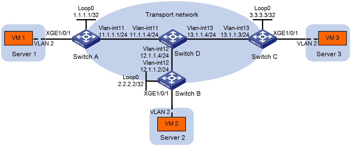
As shown in Figure 9:
· Configure VXLAN 10 as a unicast-mode VXLAN on Switch A, Switch B, and Switch C to provide Layer 2 connectivity for the VMs across the network sites.
· Manually establish VXLAN tunnels and assign the tunnels to VXLAN 10.
· Enable remote-MAC address learning.
Configuration procedure
1. Configure IP addresses and unicast routing settings:
# Assign IP addresses to interfaces, as shown in Figure 9. (Details not shown.)
# Configure OSPF on all transport network switches (Switches A through D). (Details not shown.)
2. Configure Switch A:
# Enable L2VPN.
<SwitchA> system-view
[SwitchA] l2vpn enable
# Create VSI vpna and VXLAN 10.
[SwitchA] vsi vpna
[SwitchA-vsi-vpna] vxlan 10
[SwitchA-vsi-vpna-vxlan-10] quit
[SwitchA-vsi-vpna] quit
# Assign an IP address to Loopback 0. The IP address will be used as the source IP address of the VXLAN tunnels to Switch B and Switch C.
[SwitchA] interface loopback 0
[SwitchA-Loopback0] ip address 1.1.1.1 255.255.255.255
[SwitchA-Loopback0] quit
# Create a VXLAN tunnel to Switch B. The tunnel interface name is Tunnel 1.
[SwitchA] interface tunnel 1 mode vxlan
[SwitchA-Tunnel1] source 1.1.1.1
[SwitchA-Tunnel1] destination 2.2.2.2
[SwitchA-Tunnel1] quit
# Create a VXLAN tunnel to Switch C. The tunnel interface name is Tunnel 2.
[SwitchA] interface tunnel 2 mode vxlan
[SwitchA-Tunnel2] source 1.1.1.1
[SwitchA-Tunnel2] destination 3.3.3.3
[SwitchA-Tunnel2] quit
# Assign Tunnel 1 and Tunnel 2 to VXLAN 10.
[SwitchA] vsi vpna
[SwitchA-vsi-vpna] vxlan 10
[SwitchA-vsi-vpna-vxlan-10] tunnel 1
[SwitchA-vsi-vpna-vxlan-10] tunnel 2
[SwitchA-vsi-vpna-vxlan-10] quit
[SwitchA-vsi-vpna] quit
# On Ten-GigabitEthernet 1/0/1, create Ethernet service instance 1000 to match VLAN 2.
[SwitchA] interface ten-gigabitethernet 1/0/1
[SwitchA-Ten-GigabitEthernet1/0/1] service-instance 1000
[SwitchA-Ten-GigabitEthernet1/0/1-srv1000] encapsulation s-vid 2
# Map Ethernet service instance 1000 to VSI vpna.
[SwitchA-Ten-GigabitEthernet1/0/1-srv1000] xconnect vsi vpna
[SwitchA-Ten-GigabitEthernet1/0/1-srv1000] quit
[SwitchA-Ten-GigabitEthernet1/0/1] quit
3. Configure Switch B:
# Enable L2VPN.
<SwitchB> system-view
[SwitchB] l2vpn enable
# Create VSI vpna and VXLAN 10.
[SwitchB] vsi vpna
[SwitchB-vsi-vpna] vxlan 10
[SwitchB-vsi-vpna-vxlan-10] quit
[SwitchB-vsi-vpna] quit
# Assign an IP address to Loopback 0. The IP address will be used as the source IP address of the VXLAN tunnels to Switch A and Switch C.
[SwitchB] interface loopback 0
[SwitchB-Loopback0] ip address 2.2.2.2 255.255.255.255
[SwitchB-Loopback0] quit
# Create a VXLAN tunnel to Switch A. The tunnel interface name is Tunnel 2.
[SwitchB] interface tunnel 2 mode vxlan
[SwitchB-Tunnel2] source 2.2.2.2
[SwitchB-Tunnel2] destination 1.1.1.1
[SwitchB-Tunnel2] quit
# Create a VXLAN tunnel to Switch C. The tunnel interface name is Tunnel 3.
[SwitchB] interface tunnel 3 mode vxlan
[SwitchB-Tunnel3] source 2.2.2.2
[SwitchB-Tunnel3] destination 3.3.3.3
[SwitchB-Tunnel3] quit
# Assign Tunnel 2 and Tunnel 3 to VXLAN 10.
[SwitchB] vsi vpna
[SwitchB-vsi-vpna] vxlan 10
[SwitchB-vsi-vpna-vxlan-10] tunnel 2
[SwitchB-vsi-vpna-vxlan-10] tunnel 3
[SwitchB-vsi-vpna-vxlan-10] quit
[SwitchB-vsi-vpna] quit
# On Ten-GigabitEthernet 1/0/1, create Ethernet service instance 1000 to match VLAN 2.
[SwitchB] interface ten-gigabitethernet 1/0/1
[SwitchB-Ten-GigabitEthernet1/0/1] service-instance 1000
[SwitchB-Ten-GigabitEthernet1/0/1-srv1000] encapsulation s-vid 2
# Map Ethernet service instance 1000 to VSI vpna.
[SwitchB-Ten-GigabitEthernet1/0/1-srv1000] xconnect vsi vpna
[SwitchB-Ten-GigabitEthernet1/0/1-srv1000] quit
[SwitchB-Ten-GigabitEthernet1/0/1] quit
4. Configure Switch C:
# Enable L2VPN.
<SwitchC> system-view
[SwitchC] l2vpn enable
# Create VSI vpna and VXLAN 10.
[SwitchC] vsi vpna
[SwitchC-vsi-vpna] vxlan 10
[SwitchC-vsi-vpna-vxlan-10] quit
[SwitchC-vsi-vpna] quit
# Assign an IP address to Loopback 0. The IP address will be used as the source IP address of the VXLAN tunnels to Switch A and Switch B.
[SwitchC] interface loopback 0
[SwitchC-Loopback0] ip address 3.3.3.3 255.255.255.255
[SwitchC-Loopback0] quit
# Create a VXLAN tunnel to Switch A. The tunnel interface name is Tunnel 1.
[SwitchC] interface tunnel 1 mode vxlan
[SwitchC-Tunnel1] source 3.3.3.3
[SwitchC-Tunnel1] destination 1.1.1.1
[SwitchC-Tunnel1] quit
# Create a VXLAN tunnel to Switch B. The tunnel interface name is Tunnel 3.
[SwitchC] interface tunnel 3 mode vxlan
[SwitchC-Tunnel3] source 3.3.3.3
[SwitchC-Tunnel3] destination 2.2.2.2
[SwitchC-Tunnel3] quit
# Assign Tunnel 1 and Tunnel 3 to VXLAN 10.
[SwitchC] vsi vpna
[SwitchC-vsi-vpna] vxlan 10
[SwitchC-vsi-vpna-vxlan-10] tunnel 1
[SwitchC-vsi-vpna-vxlan-10] tunnel 3
[SwitchC-vsi-vpna-vxlan-10] quit
[SwitchC-vsi-vpna] quit
# On Ten-GigabitEthernet 1/0/1, create Ethernet service instance 1000 to match VLAN 2.
[SwitchC] interface ten-gigabitethernet 1/0/1
[SwitchC-Ten-GigabitEthernet1/0/1] service-instance 1000
[SwitchC-Ten-GigabitEthernet1/0/1-srv1000] encapsulation s-vid 2
# Map Ethernet service instance 1000 to VSI vpna.
[SwitchC-Ten-GigabitEthernet1/0/1-srv1000] xconnect vsi vpna
[SwitchC-Ten-GigabitEthernet1/0/1-srv1000] quit
[SwitchC-Ten-GigabitEthernet1/0/1] quit
Verifying the configuration
1. Verify the VXLAN settings on the VTEPs. This example uses Switch A.
# Verify that the VXLAN tunnel interfaces on the VTEP are up.
[SwitchA] display interface tunnel 1
Tunnel1
Current state: UP
Line protocol state: UP
Description: Tunnel1 Interface
Bandwidth: 64 kbps
Maximum transmission unit: 1464
Internet protocol processing: Disabled
Last clearing of counters: Never
Tunnel source 1.1.1.1, destination 2.2.2.2
Tunnel protocol/transport UDP_VXLAN/IP
Last 300 seconds input rate: 0 bytes/sec, 0 bits/sec, 0 packets/sec
Last 300 seconds output rate: 0 bytes/sec, 0 bits/sec, 0 packets/sec
Input: 0 packets, 0 bytes, 0 drops
Output: 0 packets, 0 bytes, 0 drops
# Verify that the VXLAN tunnels have been assigned to the VXLAN.
[SwitchA] display l2vpn vsi verbose
VSI Name: vpna
VSI Index : 0
VSI State : Up
MTU : 1500
Bandwidth : Unlimited
Broadcast Restrain : Unlimited
Multicast Restrain : Unlimited
Unknown Unicast Restrain: Unlimited
MAC Learning : Enabled
MAC Table Limit : -
MAC Learning rate : -
Drop Unknown : -
Flooding : Enabled
Statistics : Disabled
VXLAN ID : 10
Tunnels:
Tunnel Name Link ID State Type Flood proxy
Tunnel1 0x5000001 Up Manual Disabled
Tunnel2 0x5000002 Up Manual Disabled
ACs:
AC Link ID State Type
XGE1/0/1 srv1000 0 Up Manual
# Verify that the VTEP has learned the MAC addresses of remote VMs.
<SwitchA> display l2vpn mac-address
MAC Address State VSI Name Link ID/Name Aging
cc3e-5f9c-6cdb Dynamic vpna Tunnel1 Aging
cc3e-5f9c-23dc Dynamic vpna Tunnel2 Aging
--- 2 mac address(es) found ---
2. Verify that VM 1, VM 2, and VM 3 can ping each other. (Details not shown.)
Multicast-mode VXLAN configuration example
Network requirements
As shown in Figure 10:
· Configure VXLAN 10 as a multicast-mode VXLAN on Switch A, Switch B, and Switch C to provide Layer 2 connectivity for the VMs across the network sites.
· Manually establish VXLAN tunnels and assign the tunnels to VXLAN 10.
· Enable remote-MAC address learning.
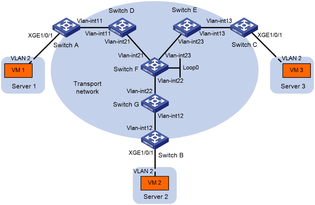
Table 1 IP address assignment
|
Device |
Interface |
IP address |
Device |
Interface |
IP address |
|
Switch A: |
|
|
Switch C: |
|
|
|
|
VLAN-interface 11 |
11.1.1.1/24 |
|
VLAN-interface 13 |
13.1.1.3/24 |
|
Switch D: |
|
|
Switch E: |
|
|
|
|
VLAN-interface 11 |
11.1.1.4/24 |
|
VLAN-interface 13 |
13.1.1.5/24 |
|
|
VLAN-interface 21 |
21.1.1.4/24 |
|
VLAN-interface 23 |
23.1.1.5/24 |
|
Switch F: |
|
|
Switch G: |
|
|
|
|
VLAN-interface 21 |
21.1.1.6/24 |
|
VLAN-interface 12 |
12.1.1.7/24 |
|
|
VLAN-interface 22 |
22.1.1.6/24 |
|
VLAN-interface 22 |
22.1.1.7/24 |
|
|
VLAN-interface 23 |
23.1.1.6/24 |
Switch B: |
|
|
|
|
Loop 0 |
6.6.6.6/32 |
|
VLAN-interface 12 |
12.1.1.2/24 |
Configuration procedure
1. Configure IP addresses and unicast routing settings:
# Assign IP addresses to interfaces, as shown in Figure 10. (Details not shown.)
# Configure OSPF on all transport network switches (Switches A through G). (Details not shown.)
2. Configure Switch A:
# Enable L2VPN.
<SwitchA> system-view
[SwitchA] l2vpn enable
# Enable IP multicast routing.
[SwitchA] multicast routing
[SwitchA-mrib] quit
# Create VSI vpna and VXLAN 10.
[SwitchA] vsi vpna
[SwitchA-vsi-vpna] vxlan 10
[SwitchA-vsi-vpna-vxlan-10] quit
[SwitchA-vsi-vpna] quit
# Assign an IP address to VLAN-interface 11, and enable the IGMP host feature on the interface. This interface's IP address will be the source IP address of VXLAN packets sent by the VTEP.
[SwitchA] interface vlan-interface 11
[SwitchA-Vlan-interface11] ip address 11.1.1.1 24
[SwitchA-Vlan-interface11] igmp host enable
[SwitchA-Vlan-interface11] quit
# Create a VXLAN tunnel to Switch B. The tunnel interface name is Tunnel 1.
[SwitchA] interface tunnel 1 mode vxlan
[SwitchA-Tunnel1] source 11.1.1.1
[SwitchA-Tunnel1] destination 12.1.1.2
[SwitchA-Tunnel1] quit
# Create a VXLAN tunnel to Switch C. The tunnel interface name is Tunnel 2.
[SwitchA] interface tunnel 2 mode vxlan
[SwitchA-Tunnel2] source 11.1.1.1
[SwitchA-Tunnel2] destination 13.1.1.3
[SwitchA-Tunnel2] quit
# Assign Tunnel 1 and Tunnel 2 to VXLAN 10.
[SwitchA] vsi vpna
[SwitchA-vsi-vpna] vxlan 10
[SwitchA-vsi-vpna-vxlan-10] tunnel 1
[SwitchA-vsi-vpna-vxlan-10] tunnel 2
# Configure the multicast group address and source IP address for multicast VXLAN packets.
[SwitchA-vsi-vpna-vxlan-10] group 225.1.1.1 source 11.1.1.1
[SwitchA-vsi-vpna-vxlan-10] quit
[SwitchA-vsi-vpna] quit
# On Ten-GigabitEthernet 1/0/1, create Ethernet service instance 1000 to match VLAN 2.
[SwitchA] interface ten-gigabitethernet 1/0/1
[SwitchA-Ten-GigabitEthernet1/0/1] service-instance 1000
[SwitchA-Ten-GigabitEthernet1/0/1-srv1000] encapsulation s-vid 2
# Map Ethernet service instance 1000 to VSI vpna.
[SwitchA-Ten-GigabitEthernet1/0/1-srv1000] xconnect vsi vpna
[SwitchA-Ten-GigabitEthernet1/0/1-srv1000] quit
[SwitchA-Ten-GigabitEthernet1/0/1] quit
3. Configure Switch B:
# Enable L2VPN.
<SwitchB> system-view
[SwitchB] l2vpn enable
# Enable IP multicast routing.
[SwitchB] multicast routing
[SwitchB-mrib] quit
# Create VSI vpna and VXLAN 10.
[SwitchB] vsi vpna
[SwitchB-vsi-vpna] vxlan 10
[SwitchB-vsi-vpna-vxlan-10] quit
[SwitchB-vsi-vpna] quit
# Assign an IP address to VLAN-interface 12, and enable the IGMP host feature on the interface. This interface's IP address will be the source IP address of VXLAN packets sent by the VTEP.
[SwitchB] interface vlan-interface 12
[SwitchB-Vlan-interface12] ip address 12.1.1.2 24
[SwitchB-Vlan-interface12] igmp host enable
[SwitchB-Vlan-interface12] quit
# Create a VXLAN tunnel to Switch A. The tunnel interface name is Tunnel 2.
[SwitchB] interface tunnel 2 mode vxlan
[SwitchB-Tunnel2] source 12.1.1.2
[SwitchB-Tunnel2] destination 11.1.1.1
[SwitchB-Tunnel2] quit
# Create a VXLAN tunnel to Switch C. The tunnel interface name is Tunnel 3.
[SwitchB] interface tunnel 3 mode vxlan
[SwitchB-Tunnel3] source 12.1.1.2
[SwitchB-Tunnel3] destination 13.1.1.3
[SwitchB-Tunnel3] quit
# Assign Tunnel 2 and Tunnel 3 to VXLAN 10.
[SwitchB] vsi vpna
[SwitchB-vsi-vpna] vxlan 10
[SwitchB-vsi-vpna-vxlan-10] tunnel 2
[SwitchB-vsi-vpna-vxlan-10] tunnel 3
# Configure the VXLAN multicast group address and the source IP address for VXLAN packets.
[SwitchB-vsi-vpna-vxlan-10] group 225.1.1.1 source 12.1.1.2
[SwitchB-vsi-vpna-vxlan-10] quit
[SwitchB-vsi-vpna] quit
# On Ten-GigabitEthernet 1/0/1, create Ethernet service instance 1000 to match VLAN 2.
[SwitchB] interface ten-gigabitethernet 1/0/1
[SwitchB-Ten-GigabitEthernet1/0/1] service-instance 1000
[SwitchB-Ten-GigabitEthernet1/0/1-srv1000] encapsulation s-vid 2
# Map Ethernet service instance 1000 to VSI vpna.
[SwitchB-Ten-GigabitEthernet1/0/1-srv1000] xconnect vsi vpna
[SwitchB-Ten-GigabitEthernet1/0/1-srv1000] quit
[SwitchB-Ten-GigabitEthernet1/0/1] quit
4. Configure Switch C:
# Enable L2VPN.
<SwitchC> system-view
[SwitchC] l2vpn enable
# Enable IP multicast routing.
[SwitchC] multicast routing
[SwitchC-mrib] quit
# Create VSI vpna and VXLAN 10.
[SwitchC] vsi vpna
[SwitchC-vsi-vpna] vxlan 10
[SwitchC-vsi-vpna-vxlan-10] quit
[SwitchC-vsi-vpna] quit
# Assign an IP address to VLAN-interface 13, and enable the IGMP host feature on the interface. This interface's IP address will be the source IP address of VXLAN packets sent by the VTEP.
[SwitchC] interface vlan-interface 13
[SwitchC-Vlan-interface13] ip address 13.1.1.3 24
[SwitchC-Vlan-interface13] igmp host enable
[SwitchC-Vlan-interface13] quit
# Create a VXLAN tunnel to Switch A. The tunnel interface name is Tunnel 1.
[SwitchC] interface tunnel 1 mode vxlan
[SwitchC-Tunnel1] source 13.1.1.3
[SwitchC-Tunnel1] destination 11.1.1.1
[SwitchC-Tunnel1] quit
# Create a VXLAN tunnel to Switch B. The tunnel interface name is Tunnel 3.
[SwitchC] interface tunnel 3 mode vxlan
[SwitchC-Tunnel3] source 13.1.1.3
[SwitchC-Tunnel3] destination 12.1.1.2
[SwitchC-Tunnel3] quit
# Assign Tunnel 1 and Tunnel 3 to VXLAN 10.
[SwitchC] vsi vpna
[SwitchC-vsi-vpna] vxlan 10
[SwitchC-vsi-vpna-vxlan-10] tunnel 1
[SwitchC-vsi-vpna-vxlan-10] tunnel 3
# Configure the multicast group address and source IP address for VXLAN multicast packets.
[SwitchC-vsi-vpna-vxlan-10] group 225.1.1.1 source 13.1.1.3
[SwitchC-vsi-vpna-vxlan-10] quit
[SwitchC-vsi-vpna] quit
# On Ten-GigabitEthernet 1/0/1, create Ethernet service instance 1000 to match VLAN 2.
[SwitchC] interface ten-gigabitethernet 1/0/1
[SwitchC-Ten-GigabitEthernet1/0/1] service-instance 1000
[SwitchC-Ten-GigabitEthernet1/0/1-srv1000] encapsulation s-vid 2
# Map Ethernet service instance 1000 to VSI vpna.
[SwitchC-Ten-GigabitEthernet1/0/1-srv1000] xconnect vsi vpna
[SwitchC-Ten-GigabitEthernet1/0/1-srv1000] quit
[SwitchC-Ten-GigabitEthernet1/0/1] quit
5. Configure Switch D:
# Enable IP multicast routing.
<SwitchD> system-view
[SwitchD] multicast routing
[SwitchD-mrib] quit
# Enable IGMP and PIM-SM on VLAN-interface 11.
[SwitchD] interface vlan-interface 11
[SwitchD-Vlan-interface11] igmp enable
[SwitchD-Vlan-interface11] pim sm
[SwitchD-Vlan-interface11] quit
# Enable PIM-SM on VLAN-interface 21.
[SwitchD] interface vlan-interface 21
[SwitchD-Vlan-interface21] pim sm
[SwitchD-Vlan-interface21] quit
# Enable BIDIR-PIM.
[SwitchD] pim
[SwitchD-pim] bidir-pim enable
[SwitchD-pim] quit
6. Configure Switch E:
# Enable IP multicast routing.
<SwitchE> system-view
[SwitchE] multicast routing
[SwitchE-mrib] quit
# Enable IGMP and PIM-SM on VLAN-interface 13.
[SwitchE] interface vlan-interface 13
[SwitchE-Vlan-interface13] igmp enable
[SwitchE-Vlan-interface13] pim sm
[SwitchE-Vlan-interface13] quit
# Enable PIM-SM on VLAN-interface 23.
[SwitchE] interface vlan-interface 23
[SwitchE-Vlan-interface23] pim sm
[SwitchE-Vlan-interface23] quit
# Enable BIDIR-PIM.
[SwitchE] pim
[SwitchE-pim] bidir-pim enable
[SwitchE-pim] quit
7. Configure Switch F:
# Enable IP multicast routing.
<SwitchF> system-view
[SwitchF] multicast routing
[SwitchF-mrib] quit
# Enable PIM-SM on VLAN-interface 21, VLAN-interface 22, VLAN-interface 23, and Loopback 0.
[SwitchF] interface vlan-interface 21
[SwitchF-Vlan-interface21] pim sm
[SwitchF-Vlan-interface21] quit
[SwitchF] interface vlan-interface 22
[SwitchF-Vlan-interface22] pim sm
[SwitchF-Vlan-interface22] quit
[SwitchF] interface vlan-interface 23
[SwitchF-Vlan-interface23] pim sm
[SwitchF-Vlan-interface23] quit
[SwitchF] interface loopback 0
[SwitchF-LoopBack0] pim sm
[SwitchF-LoopBack0] quit
# Enable BIDIR-PIM.
[SwitchF] pim
[SwitchF-pim] bidir-pim enable
# Configure VLAN-interface 22 as a candidate-BSR, and configure Loopback 0 as a candidate-RP for BIDIR-PIM.
[SwitchF-pim] c-bsr 22.1.1.6
[SwitchF-pim] c-rp 6.6.6.6 bidir
[SwitchF-pim] quit
8. Configure Switch G:
# Enable IP multicast routing.
<SwitchG> system-view
[SwitchG] multicast routing
[SwitchG-mrib] quit
# Enable IGMP and PIM-SM on VLAN-interface 12.
[SwitchG] interface vlan-interface 12
[SwitchG-Vlan-interface12] igmp enable
[SwitchG-Vlan-interface12] pim sm
[SwitchG-Vlan-interface12] quit
# Enable PIM-SM on VLAN-interface 22.
[SwitchG] interface vlan-interface 22
[SwitchG-Vlan-interface22] pim sm
[SwitchG-Vlan-interface22] quit
# Enable BIDIR-PIM.
[SwitchG] pim
[SwitchG-pim] bidir-pim enable
[SwitchG-pim] quit
Verifying the configuration
1. Verify the VXLAN settings on the VTEPs. This example uses Switch A.
# Verify that the VXLAN tunnel interfaces on the VTEP are up.
[SwitchA] display interface tunnel 1
Tunnel1
Current state: UP
Line protocol state: UP
Description: Tunnel1 Interface
Bandwidth: 64 kbps
Maximum transmission unit: 1464
Internet protocol processing: Disabled
Last clearing of counters: Never
Tunnel source 11.1.1.1, destination 12.1.1.2
Tunnel protocol/transport UDP_VXLAN/IP
Last 300 seconds input rate: 0 bytes/sec, 0 bits/sec, 0 packets/sec
Last 300 seconds output rate: 0 bytes/sec, 0 bits/sec, 0 packets/sec
Input: 0 packets, 0 bytes, 0 drops
Output: 0 packets, 0 bytes, 0 drops
# Verify that the VXLAN tunnels have been assigned to the VXLAN.
[SwitchA] display l2vpn vsi verbose
VSI Name: vpna
VSI Index : 0
VSI State : Up
MTU : 1500
Bandwidth : Unlimited
Broadcast Restrain : Unlimited
Multicast Restrain : Unlimited
Unknown Unicast Restrain: Unlimited
MAC Learning : Enabled
MAC Table Limit : -
MAC Learning rate : -
Drop Unknown : -
Flooding : Enabled
Statistics : Disabled
VXLAN ID : 10
Tunnels:
Tunnel Name Link ID State Type Flood proxy
Tunnel1 0x5000001 Up Manual Disabled
Tunnel2 0x5000002 Up Manual Disabled
MTunnel0 0x6000000 Up Auto Disabled
ACs:
AC Link ID State Type
XGE1/0/1 srv1000 0 Up Manual
# Verify that the VTEP has learned the MAC addresses of remote VMs.
<SwitchA> display l2vpn mac-address
MAC Address State VSI Name Link ID/Name Aging
cc3e-5f9c-6cdb Dynamic vpna Tunnel1 Aging
cc3e-5f9c-23dc Dynamic vpna Tunnel2 Aging
--- 2 mac address(es) found ---
# Verify that the VTEP has joined the VXLAN multicast group on VLAN-interface 11.
<SwitchA> display igmp host group
IGMP host groups in total: 1
Vlan-interface11(11.1.1.1):
IGMP host groups in total: 1
Group address Member state Expires
225.1.1.1 Idle Off
2. Verify that VM 1, VM 2, and VM 3 can ping each other. (Details not shown.)
Configuring VXLAN IP gateways
Overview
The following are available IP gateway placement designs for VXLANs:
· VXLAN IP gateways separated from VTEPs—Use a VXLAN-unaware device as a gateway to the external network for VXLANs. On the gateway, you do not need to configure VXLAN settings.
· VXLAN IP gateways collocated with VTEPs—Include the following placement designs:
¡ Centralized VXLAN IP gateway deployment—Use one VTEP to provide Layer 3 forwarding for VXLANs. Typically, the gateway-collocated VTEP connects to other VTEPs and the external network. To use this design, make sure the IP gateway has sufficient bandwidth and processing capability. Centralized VXLAN IP gateways provide services only for IPv4 networks.
¡ Centralized VXLAN gateway group deployment—Use one VTEP group that contains redundant centralized VXLAN IP gateways to provide reliable gateway services for VXLANs.
¡ Distributed VXLAN IP gateway deployment—Deploy one VXLAN IP gateway on each VTEP to provide Layer 3 forwarding for VXLANs at their respective sites. This design distributes the Layer 3 traffic load across VTEPs. However, its configuration is more complex than the centralized VXLAN IP gateway design. Distributed gateways can provide services for both IPv4 and IPv6 networks.
In a collocation design, the VTEPs use virtual Layer 3 VSI interfaces as gateway interfaces to provide services for VXLANs.
VXLAN IP gateways separated from VTEPs
As shown in Figure 11, an independent VXLAN IP gateway connects a Layer 3 network to a VTEP. VMs send Layer 3 traffic in Layer 2 frames to the gateway through VXLAN tunnels. When the tunneled VXLAN packets arrive, the VTEP terminates the VXLANs and forwards the inner frames to the gateway. In this gateway placement design, the VTEP does not perform Layer 3 forwarding for VXLANs.
Figure 11 VXLAN IP gateway separated from VTEPs
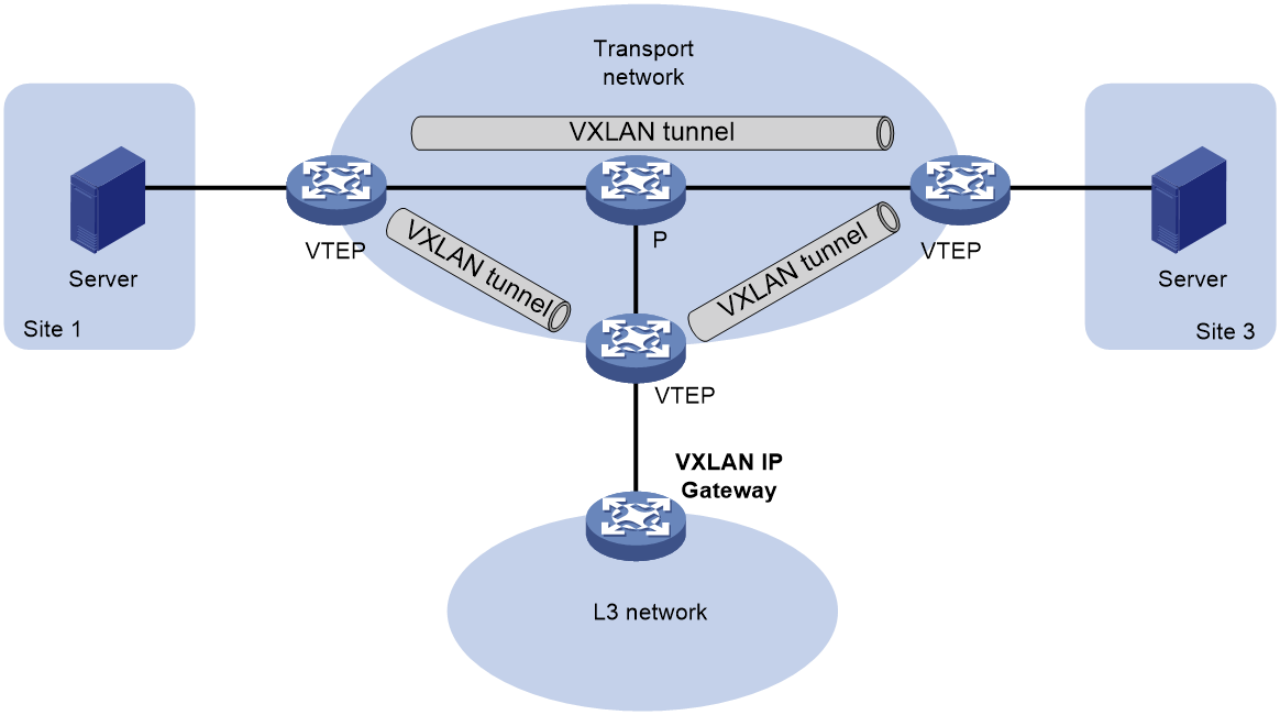
Centralized VXLAN IP gateway deployment
|
|
NOTE: Centralized VXLAN IP gateways support only IPv4 sites. |
As shown in Figure 12, a VTEP acts as a gateway for VMs in the VXLANs. The VTEP both terminates the VXLANs and performs Layer 3 forwarding for the VMs.
Figure 12 Centralized VXLAN IP gateway placement design
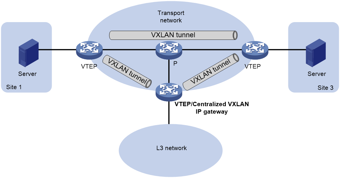
As shown in Figure 13, the network uses the following process to forward Layer 3 traffic from VM 10.1.1.11 to the Layer 3 network:
1. The VM sends an ARP request to obtain the MAC address of the gateway (VTEP 3) at 10.1.1.1.
2. VTEP 1 floods the ARP request to all remote VTEPs.
3. VTEP 3 de-encapsulates the ARP request, creates an ARP entry for the VM, and sends an ARP reply to the VM.
4. VTEP 1 forwards the ARP reply to the VM.
5. The VM learns the MAC address of the gateway, and sends the Layer 3 traffic to the gateway.
6. VTEP 3 removes the VXLAN encapsulation and inner Ethernet header for the traffic, and forwards the traffic to the destination node.
Inter-VXLAN forwarding is the same as this process except for the last step. At the last step of inter-VLAN forwarding, the gateway replaces the source-VXLAN encapsulation with the destination-VXLAN encapsulation, and then forwards the traffic.
Figure 13 Example of centralized VXLAN IP gateway deployment
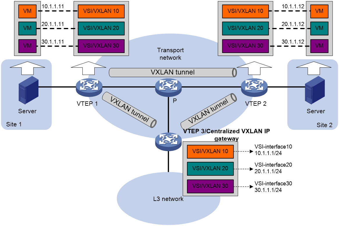
Centralized VXLAN gateway group deployment
As shown in Figure 14, a VTEP group uses redundant centralized VXLAN IP gateways to provide reliable gateway services for VMs in the VXLANs. All member VTEPs in the group participate in Layer 3 forwarding and load share traffic between the Layer 3 network and the VXLANs. This design distributes processing among multiple VTEPs and prevents single points of failure.
Figure 14 Example of centralized VXLAN IP gateway group deployment
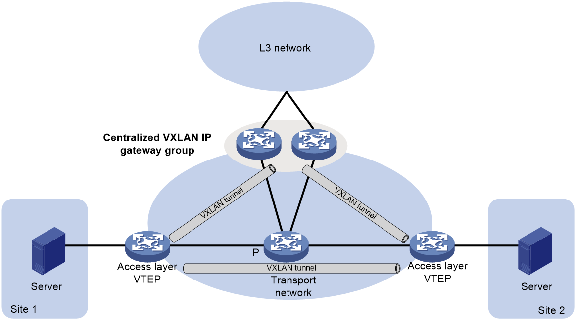
The VTEP group is a virtual gateway that provides services at a group IP address. Access layer VTEPs set up VXLAN tunnels to the group IP address for data traffic forwarding. Each access layer VTEP also automatically sets up tunnels to the member IP addresses of VTEPs in the VTEP group. For all VTEPs in the VTEP group to have consistent forwarding entries, these tunnels are used for transmitting broadcast, multicast, and unknown unicast floods.
Distributed VXLAN IP gateway deployment
As shown in Figure 15, each site's VTEP acts as a gateway to perform Layer 3 forwarding for the VXLANs of the local site. A VTEP acts as a border gateway to the Layer 3 network for the VXLANs.
Figure 15 Distributed VXLAN IP gateway placement design
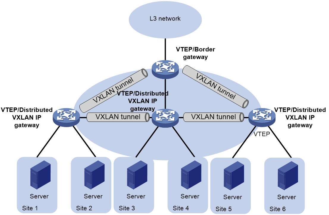
Figure 16 shows an example of distributed VXLAN IP gateway deployment. VSI interfaces are created on each distributed VXLAN IP gateway and the border gateway as gateway interfaces. The same VSI interface uses the same IP address on the distributed VXLAN IP gateways. You must enable one of the following features on a distributed VXLAN IP gateway:
· ARP and ND flood suppression. The gateway performs Layer 2 forwarding based on MAC address entries and performs Layer 3 forwarding based on ARP and ND entries.
· Local proxy ARP or local ND proxy. The gateway performs Layer 3 forwarding based on ARP or ND entries. The following sections use distributed VXLAN IP gateways enabled with the local proxy ARP or local ND proxy feature to describe the forwarding processes for intra-VXLAN traffic, inter-VXLAN traffic, and traffic from a VXLAN to an external network.
Figure 16 Example of distributed VXLAN IP gateway deployment
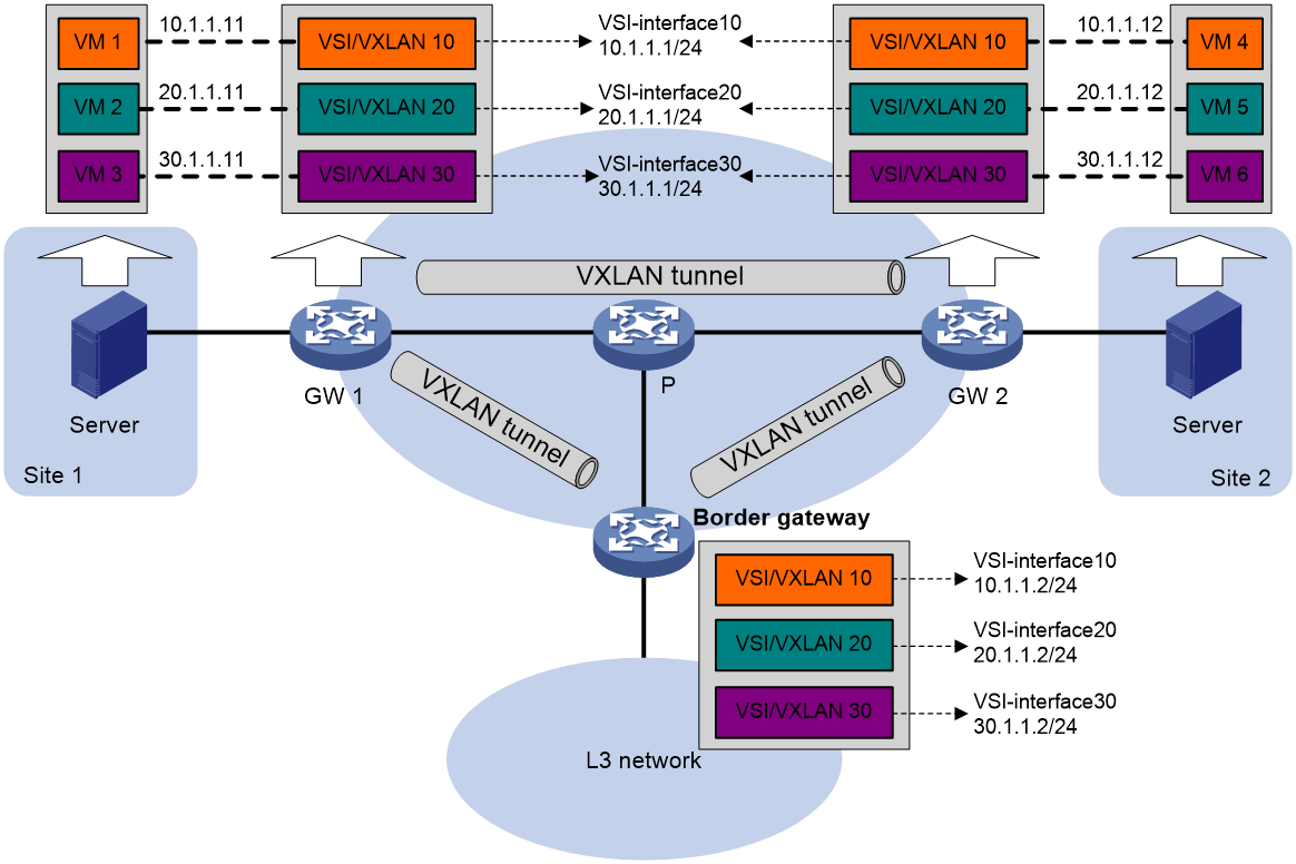
Intra-VXLAN traffic forwarding between sites
As shown in Figure 16, the network uses the following process to forward traffic in a VXLAN between sites (for example, from VM 1 to VM 4 in VXLAN 10):
1. VM 1 sends an ARP request to obtain the MAC address of VM 4.
2. GW 1 performs the following operations:
a. Creates an ARP entry for VM 1 and replies with the MAC address of VSI-interface 10 (the gateway interface for VXLAN 10).
b. Replaces the sender MAC address of the ARP request with the MAC address of VSI-interface 10, and then floods the request to all remote VTEPs.
3. VM 1 creates an ARP entry for VM 4. The MAC address in the entry is the MAC address of VSI-interface 10 on GW 1.
4. GW 2 (the VTEP for VM 4) performs the following operations:
a. De-encapsulates the ARP request and creates an ARP entry for VM 1. The entry contains VM 1's IP address (10.1.1.11), the MAC address of VSI-interface 10 on GW 1, and the incoming tunnel interface.
b. Replaces the sender MAC address of the request with the MAC address of VSI-interface 10 on GW 2, and then floods the request to the local site in VXLAN 10.
5. VM 4 creates an ARP entry for VM 1, and then sends a reply to GW 2. The MAC address in the ARP entry is the MAC address of VSI-interface 10 on GW 2.
6. GW 2 performs the following operations:
a. Creates an ARP entry for VM 4.
b. Replaces the sender MAC address of the reply with the MAC address of VSI-interface 10 on GW 2, and sends the reply to GW 1.
7. GW 1 de-encapsulates the ARP reply and creates an ARP entry for VM 4. The entry contains VM 4's IP address (10.1.1.12), the MAC address of VSI-interface 10 on GW 2, and the incoming tunnel interface.
8. For subsequent traffic between VM 1 and VM 4, GW 1 and GW 2 use their respective ARP tables to make the forwarding decision.
Inter-VXLAN traffic forwarding between sites
As shown in Figure 17, the network uses the following process to forward traffic between VXLANs (for example, from VM 1 in VXLAN 10 to VM 5 in VXLAN 20):
1. VM 1 sends an ARP request to obtain the MAC address of the gateway at 10.1.1.1.
2. GW 1 creates an ARP entry for VM 1 and replies with the MAC address of VSI-interface 10 (the gateway interface for VXLAN 10) so VM 1 will send the packets destined for VM 5 to GW 1.
3. GW 1 sends an ARP request to the local and remote sites in VXLAN 10. In the ARP request, the sender IP address is 10.1.1.11, and the sender MAC address is the MAC address of VSI-interface 10 on GW 1.
4. GW 2 performs the following operations:
a. De-encapsulates the ARP request and creates an ARP entry for VM 1. The entry contains IP address 10.1.1.11 and MAC address of VSI-interface 10 on GW 1, and the incoming tunnel interface.
b. Replaces the sender MAC address of the request with the MAC address of VSI-interface 10 on GW 2, and then floods the request to the local site in VXLAN 10.
c. Sends an ARP reply to GW 1. The reply contains IP address 10.1.1.1 and MAC address of VSI-interface 10 on GW 2).
5. When sending an ARP request in VXLAN 10, GW 1 also sends an ARP request to the local and remote sites in VXLAN 20 to obtain the MAC address of VM 5. In the ARP request, the sender IP address is 20.1.1.1, and the sender MAC address is the MAC address of VSI-interface 20 on GW 1.
6. GW 2 de-encapsulates the ARP request of VXLAN 20, replaces the sender MAC address of the request with the MAC address of VSI-interface 20 on GW 2, and then floods the request to the local site in VXLAN 20.
7. VM 5 creates an ARP entry for GW 2, and then sends a reply to GW 2. The entry contains IP address 20.1.1.1 and MAC address of VSI-interface 20 on GW 2.
8. GW 2 performs the following operations:
a. Creates an ARP entry for VM 5.
b. Sends a gratuitous ARP packet to the local and remote sites. In the packet, the sender IP address is 20.1.1.12, and the sender MAC address is the MAC address of VSI-interface 20 on GW 2.
9. GW 1 de-encapsulates the gratuitous ARP packet and creates an ARP entry for VM 5. The entry contains VM 5's IP address 20.1.1.12, the MAC address of VSI-interface 20 on GW 2, and the incoming tunnel interface.
10. For subsequent traffic between VM 1 and VM 5, GW 1 and GW 2 use their respective ARP tables to make the forwarding decision.
Figure 17 Inter-VXLAN traffic forwarding between sites

VXLAN-to-external network traffic forwarding
As shown in Figure 16, the network uses the following process to forward traffic from a VXLAN to the Layer 3 network (for example, from VM 1 to the host at 50.1.1.1):
1. VM 1 sends an ARP request to obtain the MAC address of the gateway at 10.1.1.1.
2. GW 1 creates an ARP entry for VM 1 and replies with the MAC address of VSI-interface 10 (the gateway interface for VXLAN 10).
3. VM 1 sends a packet destined for the host to GW 1.
4. GW 1 performs the following operations:
a. Searches the IP routing policies or routing table for the next hop. In this example, the next hop for the packet is 10.1.1.2 (the border gateway).
b. Floods an ARP request to the local and remote sites in VXLAN 10 to obtain the MAC address of 10.1.1.2.
5. The border gateway de-encapsulates the ARP request, creates an ARP entry for GW 1, and tunnels a reply to GW 1.
6. GW 1 de-encapsulates the ARP reply and creates an ARP entry for 10.1.1.2.
7. GW 1 sends the packet destined for the host to the border gateway.
8. The border gateway de-encapsulates the packet and forwards it to the host.
Feature and hardware compatibility
VXLAN IP gateways are not supported on switches labeled with the following product codes:
· LS-6800-2C.
· LS-6800-4C.
· LS-6800-32Q.
· LS-6800-54QF.
· LS-6800-54QT.
Configuration restrictions and guidelines
When you configure VXLAN IP gateways, follow these restrictions and guidelines:
|
Device role |
Configuration |
Restrictions and guidelines |
|
VXLAN IP gateway |
Ethernet service instance and access mode |
· Use the Ethernet access mode if an Ethernet service instance uses the encapsulation untagged criterion. · Use the VLAN access mode if an Ethernet service instance uses the encapsulation s-vid { vlan-id [ only-tagged ] | vlan-id-list } criterion. |
|
Priority trust mode |
A VXLAN IP gateway processes the DSCP precedence in frames received from an AC as follows: · For Layer 3 forwarding, the gateway always uses the DSCP precedence for priority mapping, regardless of whether you configure the qos trust dscp command on the incoming interface. · For Layer 2 forwarding, the gateway uses the DSCP precedence for priority mapping only when the qos trust dscp command is configured on the incoming interface. |
|
|
PBR |
A PBR policy cannot match VXLAN packets by the source and destination IP addresses in the outer IP header on a Layer 3 interface (VSI interfaces not included). To match VXLAN packets by the source and destination IP addresses in the outer IP header, apply a PBR policy to a VSI interface. |
|
|
VTEP |
PBR |
On a Layer 3 interface, a PBR policy cannot match VXLAN packets by the source and destination IP addresses in the outer IP header. |
|
Border gateway |
ACL |
An ACL applied to a Layer 3 Ethernet interface or Layer 3 aggregate interface matches packets on both the interface and its subinterfaces. For more information about ACLs, see ACL and QoS Configuration Guide. |
|
QoS |
· A QoS policy applied to a Layer 3 Ethernet interface also takes effect on its subinterfaces if the QoS policy does not contain inner and outer VLAN ID match criteria. For more information about QoS policies, see ACL and QoS Configuration Guide. · If a QoS policy is applied to an interface other than a Layer 3 Ethernet interface, the inner and outer VLAN ID match criteria in the QoS policy cannot match untagged packets that are forwarded at Layer 3. |
|
|
PBR |
A PBR policy applied to a Layer 3 Ethernet interface or Layer 3 aggregate interface takes effect on both the interface and its subinterfaces. For more information about PBR, see Layer 3—IP Routing Configuration Guide. |
|
|
Storm suppression |
Broadcast, multicast, or unknown unicast storm suppression configured on a Layer 3 Ethernet interface takes effect on both the interface and its subinterfaces. For more information about storm suppression, see Layer 2—LAN Switching Configuration Guide. |
|
|
MAC address assignment |
Do not use the mac-address command to assign MAC addresses to the following interfaces: · Layer 3 Ethernet interfaces. · Layer 3 Ethernet subinterfaces. · Layer 3 aggregate interfaces. · Layer 3 aggregate subinterfaces. |
|
|
ARP |
You cannot execute the arp mode uni command on interfaces of a Layer 3 border gateway. For more information about this command, see ARP commands in Layer 3—IP Services Command Reference. |
Configuration prerequisites
Before you configure a centralized or distributed VXLAN IP gateway, you must perform the following tasks on VTEPs:
· Create VSIs and VXLANs.
· Configure VXLAN tunnels and assign them to VXLANs.
Configuring a centralized VXLAN IP gateway
|
Step |
Command |
Remarks |
|
1. Enter system view. |
system-view |
N/A |
|
2. Create a VSI interface and enter VSI interface view. |
interface vsi-interface vsi-interface-id |
By default, no VSI interfaces exist. |
|
3. Assign an IPv4 address to the VSI interface. |
ip address ip-address { mask | mask-length } |
By default, no IPv4 address is assigned to a VSI interface. |
|
4. Return to system view. |
quit |
N/A |
|
5. Enter VSI view. |
vsi vsi-name |
N/A |
|
6. Specify a gateway interface for the VSI. |
gateway vsi-interface vsi-interface-id |
By default, no gateway interface is specified for a VSI. |
Configuring a centralized VXLAN IP gateway group
Configuration restrictions and guidelines
A centralized VXLAN IP gateway group is exclusive with the VSI flood confining feature in some conditions. When you use the features together, follow these restrictions and guidelines:
· A gateway group can work correctly only when flooding is enabled for VSIs or when both unknown unicast and unknown multicast floods are suppressed.
· As a best practice, finish gateway group configuration before you configure VSI flood confining. The system will display prompts when the VSI flood confining setting conflicts with the gateway group configuration.
To ensure correct traffic forwarding, do not configure multicast mode or flood proxy mode for a VXLAN that uses a centralized VXLAN IP gateway group. For more information about multicast mode and flood proxy mode, see "Flood."
Configuring a VTEP group
Make sure the member VTEPs use the same VXLAN settings.
Configure a VTEP group on a member VTEP:
|
Step |
Command |
Remarks |
|
1. Enter system view. |
system-view |
N/A |
|
2. Create a VSI interface and enter VSI interface view. |
interface vsi-interface vsi-interface-id |
By default, no VSI interfaces exist. You must create the same VSI interface on all VTEPs in the VTEP group. |
|
3. Assign an IP address to the VSI interface. |
ip address ip-address { mask | mask-length } |
By default, no IP address is assigned to a VSI interface. You must assign the same IP address to the VSI interface on each VTEP in the VTEP group. |
|
4. Assign a MAC address to the VSI interface. |
mac-address mac-address |
By default, all VSI interfaces on a device use a fixed MAC address. The MAC addresses of VSI interfaces on different devices are different. You must assign the same MAC address to the VSI interface on each VTEP in the VTEP group. |
|
5. Return to system view. |
quit |
N/A |
|
6. Enter VSI view. |
vsi vsi-name |
N/A |
|
7. Specify a gateway interface for the VSI. |
gateway vsi-interface vsi-interface-id |
By default, no gateway interface is specified for a VSI. |
|
8. Return to system view. |
quit |
N/A |
|
9. Assign the local VTEP to a VTEP group and specify the member IP address for the VTEP. |
vtep group group-ip member local member-ip |
By default, a VTEP is not assigned to any VTEP group. Perform this task on all member VTEPs in the VTEP group. The IP address specified by the member-ip argument must already exist on the local VTEP. You must configure a routing protocol to advertise the IP address in the transport network. Member VTEPs in a VTEP group cannot use the group IP address or share an IP address. |
|
10. Specify all the other VTEPs in the VTEP group. |
vtep group group-ip member remote member-ip&<1-8> |
By default, no VTEP group is specified. Perform this task on all member VTEPs in the VTEP group. |
Specifying a VTEP group as the gateway for an access layer VTEP
Before you specify a VTEP group on an access layer VTEP, perform the following tasks on the VTEP:
· Configure VSIs and VXLANs.
· Set up VXLAN tunnels to remote sites and the VTEP group, and assign the tunnels to VXLANs.
To specify a VTEP group as the gateway for an access layer VTEP:
|
Step |
Command |
Remarks |
|
1. Enter system view. |
system-view |
N/A |
|
2. Specify a VTEP group and all its member VTEPs. |
vtep group group-ip member remote member-ip&<1-8> |
By default, no VTEP group is specified. |
Configuring a distributed VXLAN IP gateway
Configuration restrictions and guidelines
Make sure a VSI interface uses the same MAC address to provide service on distributed VXLAN IP gateways connected to different sites. Make sure a VSI interface uses different link-local addresses to provide service on distributed VXLAN IP gateways connected to both IPv4 and IPv6 sites.
If both ARP (or ND) flood suppression and local proxy ARP (or local ND proxy) are enabled on a distributed VXLAN IP gateway, only ARP (or ND) flood suppression takes effect. As a best practice, do not use these features together on distributed VXLAN IP gateways. For more information about ARP (or ND) flood suppression, see "Enabling ARP flood suppression" or "Enabling ND flood suppression."
On a distributed VXLAN IP gateway, you must disable source MAC check on all transport-facing interfaces by using the undo mac-address static source-check enable command. If the gateway is an IRF fabric, you must also disable the feature on all IRF ports.
On a distributed VXLAN IP gateway, you must perform the following tasks when the spanning tree feature is enabled on an interface that hosts Ethernet service instances:
1. Create the matching VLANs of the Ethernet service instances.
2. Assign the interface to the VLANs.
Configuration prerequisites
For a VXLAN that requires access to the external network, specify the VXLAN's VSI interface on the border gateway as the next hop by using one of the following methods:
· Configure a static route.
· Configure a PBR policy, and apply the policy by using the apply next-hop command. For more information about configuring PBR policies, see PBR configuration in Layer 3—IP Routing Configuration Guide.
Configuration procedure
To configure a distributed VXLAN IP gateway:
|
Step |
Command |
Remarks |
|
1. Enter system view. |
system-view |
N/A |
|
2. Create a VSI interface and enter VSI interface view. |
interface vsi-interface vsi-interface-id |
By default, no VSI interfaces exist. |
|
3. Assign an IPv4 or IPv6 address to the VSI interface. |
· Assign an IPv4 address: · Assign an IPv6 address: |
By default, no IPv4 or IPv6 address is assigned to a VSI interface. This interface will be used as a gateway for VXLANs. |
|
4. Specify the VSI interface as a distributed gateway. |
distributed-gateway local |
By default, a VSI interface is not a distributed gateway. |
|
5. Enable local proxy ARP or local ND proxy. |
· Enable local proxy ARP on an IPv4 gateway: · Enable local ND proxy on an IPv6
gateway: |
By default, local proxy ARP and local ND proxy are disabled. For more information about the commands, see Layer 3—IP Services Command Reference. |
|
6. Return to system view. |
quit |
N/A |
|
7. (Optional.) Enable dynamic ARP or ND entry synchronization for distributed VXLAN IP gateways. |
· Enable dynamic ARP entry
synchronization for distributed VXLAN IP gateways: · Enable dynamic ND entry synchronization
for distributed VXLAN IP gateways |
By default, dynamic ARP or ND entry synchronization is disabled for distributed VXLAN IP gateways. When local proxy ARP or local ND proxy is enabled on distributed VXLAN IP gateways, each gateway learns ARP or ND information independently. A gateway does not forward ARP or ND packets destined for it to other gateways. For distributed VXLAN IP gateways to have the same ARP or ND entries, you must enable dynamic ARP or ND entry synchronization. A controller or the EVPN feature can also synchronize ARP or ND entries among distributed VXLAN IP gateways. When you use a controller or the EVPN feature, do not enable dynamic ARP or ND entry synchronization. |
|
8. Enter VSI view. |
vsi vsi-name |
N/A |
|
9. Specify the VSI interface as the gateway interface for the VSI. |
gateway vsi-interface vsi-interface-id |
By default, no gateway interface is specified for a VSI. Multiple VSIs cannot share a VSI interface. |
|
10. Assign a subnet to the VSI. |
gateway subnet { ipv4-address wildcard-mask | ipv6-address prefix-length } |
By default, no subnet exists on a VSI. |
Adding a static ARP entry
|
Step |
Command |
Remarks |
|
1. Enter system view. |
system-view |
N/A |
|
2. Add a static local-ARP entry. |
arp static ip-address mac-address vsi-interface vsi-interface-id interface-type interface-number service-instance instance-id vsi vsi-name [ vpn-instance vpn-instance-name ] |
By default, no static local-ARP entries exist. For more information about this command, see ARP commands in Layer 3—IP Services Command Reference. |
|
3. Add a static remote-ARP entry. |
arp static ip-address mac-address vsi-interface vsi-interface-id tunnel number vsi vsi-name [ vpn-instance vpn-instance-name ] |
By default, no static remote-ARP entries exist. For more information about this command, see ARP commands in Layer 3—IP Services Command Reference. |
Configuring a VSI interface
|
Step |
Command |
Remarks |
|
1. Enter system view. |
system-view |
N/A |
|
2. Enter VSI interface view. |
interface vsi-interface vsi-interface-id |
N/A |
|
3. Assign a MAC address to the VSI interface. |
mac-address mac-address |
By default, all VSI interfaces on a device use a fixed MAC address. The MAC addresses of VSI interfaces on different devices are different. |
|
4. Configure the description of the VSI interface. |
description text |
The default description of a VSI interface is interface-name plus Interface (for example, Vsi-interface100 Interface). |
|
5. Set the MTU for the VSI interface. |
mtu mtu-value |
The default MTU of a VSI interface is 1444 bytes. Make sure the MTU is a minimum of 36 bytes less than the MTU of the physical outgoing interface. |
|
6. Set the expected bandwidth for the VSI interface. |
bandwidth bandwidth-value |
The default expected bandwidth (in kbps) equals the interface baud rate divided by 1000. |
|
7. Restore the default settings on the interface. |
default |
N/A |
|
8. Set an ARP packet sending rate limit for the VSI interface. |
arp send-rate pps |
By default, the ARP packet sending rate is not limited for a VSI interface. |
|
9. Bring up the interface. |
undo shutdown |
By default, a VSI interface is not manually shut down. |
Enabling packet statistics for a VSI interface
To enable packet statistics for a VSI and its associated VSI interface, execute the statistics enable command in VSI view.
To enable packet statistics for a VSI interface:
|
Step |
Command |
Remarks |
|
1. Enter system view. |
system-view |
N/A |
|
2. Enter VSI view. |
vsi vsi-name |
N/A |
|
3. Enable packet statistics for the VSI. |
statistics enable |
By default, the packet statistics feature is disabled for all VSIs. |
Displaying and maintaining VXLAN IP gateway
Execute display commands in any view and reset commands in user view.
|
Task |
Command |
|
Display information about VSI interfaces. |
display interface [ vsi-interface [ vsi-interface-id ] ] [ brief [ description | down ] ] |
|
Clear statistics on VSI interfaces. |
reset counters interface [ vsi-interface [ vsi-interface-id ] ] |
VXLAN IP gateway configuration examples
Centralized VXLAN IP gateway configuration example
Network requirements
As shown in Figure 18:
· Configure VXLAN 10 as a unicast-mode VXLAN on Switch A, Switch B, and Switch C to provide connectivity for the VMs across the network sites.
· Configure a centralized VXLAN IP gateway on Switch B to provide gateway services for VXLAN 10.
· Manually establish VXLAN tunnels and assign the tunnels to VXLAN 10.
· Enable remote-MAC address learning.
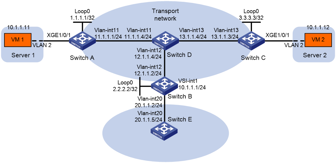
Configuration procedure
1. On VM 1 and VM 2, specify 10.1.1.1 as the gateway address. (Details not shown.)
2. Configure IP addresses and unicast routing settings:
# Assign IP addresses to interfaces, as shown in Figure 18. (Details not shown.)
# Configure OSPF on all transport network switches (Switches A through D). (Details not shown.)
# Configure OSPF to advertise routes to networks 10.1.1.0/24 and 20.1.1.0/24 on Switch B and Switch E. (Details not shown.)
3. Configure Switch A:
# Enable L2VPN.
<SwitchA> system-view
[SwitchA] l2vpn enable
# Create VSI vpna and VXLAN 10.
[SwitchA] vsi vpna
[SwitchA-vsi-vpna] vxlan 10
[SwitchA-vsi-vpna-vxlan-10] quit
[SwitchA-vsi-vpna] quit
# Assign an IP address to Loopback 0. The IP address will be used as the source IP address of the VXLAN tunnels to Switch B and Switch C.
[SwitchA] interface loopback 0
[SwitchA-Loopback0] ip address 1.1.1.1 255.255.255.255
[SwitchA-Loopback0] quit
# Create a VXLAN tunnel to Switch B. The tunnel interface name is Tunnel 1.
[SwitchA] interface tunnel 1 mode vxlan
[SwitchA-Tunnel1] source 1.1.1.1
[SwitchA-Tunnel1] destination 2.2.2.2
[SwitchA-Tunnel1] quit
# Create a VXLAN tunnel to Switch C. The tunnel interface name is Tunnel 2.
[SwitchA] interface tunnel 2 mode vxlan
[SwitchA-Tunnel2] source 1.1.1.1
[SwitchA-Tunnel2] destination 3.3.3.3
[SwitchA-Tunnel2] quit
# Assign Tunnel 1 and Tunnel 2 to VXLAN 10.
[SwitchA] vsi vpna
[SwitchA-vsi-vpna] vxlan 10
[SwitchA-vsi-vpna-vxlan-10] tunnel 1
[SwitchA-vsi-vpna-vxlan-10] tunnel 2
[SwitchA-vsi-vpna-vxlan-10] quit
[SwitchA-vsi-vpna] quit
# On Ten-GigabitEthernet 1/0/1, create Ethernet service instance 1000 to match VLAN 2.
[SwitchA] interface ten-gigabitethernet 1/0/1
[SwitchA-Ten-GigabitEthernet1/0/1] service-instance 1000
[SwitchA-Ten-GigabitEthernet1/0/1-srv1000] encapsulation s-vid 2
# Map Ethernet service instance 1000 to VSI vpna.
[SwitchA-Ten-GigabitEthernet1/0/1-srv1000] xconnect vsi vpna
[SwitchA-Ten-GigabitEthernet1/0/1-srv1000] quit
[SwitchA-Ten-GigabitEthernet1/0/1] quit
4. Configure Switch B:
# Enable L2VPN.
<SwitchB> system-view
[SwitchB] l2vpn enable
# Set the VXLAN hardware resource mode.
[SwitchB] hardware-resource vxlan l3gw8k
# Create VSI vpna and VXLAN 10.
[SwitchB] vsi vpna
[SwitchB-vsi-vpna] vxlan 10
[SwitchB-vsi-vpna-vxlan-10] quit
[SwitchB-vsi-vpna] quit
# Assign an IP address to Loopback 0. The IP address will be used as the source IP address of the VXLAN tunnels to Switch A and Switch C.
[SwitchB] interface loopback 0
[SwitchB-Loopback0] ip address 2.2.2.2 255.255.255.255
[SwitchB-Loopback0] quit
# Create a VXLAN tunnel to Switch A. The tunnel interface name is Tunnel 2.
[SwitchB] interface tunnel 2 mode vxlan
[SwitchB-Tunnel2] source 2.2.2.2
[SwitchB-Tunnel2] destination 1.1.1.1
[SwitchB-Tunnel2] quit
# Create a VXLAN tunnel to Switch C. The tunnel interface name is Tunnel 3.
[SwitchB] interface tunnel 3 mode vxlan
[SwitchB-Tunnel3] source 2.2.2.2
[SwitchB-Tunnel3] destination 3.3.3.3
[SwitchB-Tunnel3] quit
# Assign Tunnel 2 and Tunnel 3 to VXLAN 10.
[SwitchB] vsi vpna
[SwitchB-vsi-vpna] vxlan 10
[SwitchB-vsi-vpna-vxlan-10] tunnel 2
[SwitchB-vsi-vpna-vxlan-10] tunnel 3
[SwitchB-vsi-vpna-vxlan-10] quit
[SwitchB-vsi-vpna] quit
# Create VSI-interface 1 and assign the interface an IP address. The IP address will be used as the gateway address for VXLAN 10.
[SwitchB] interface vsi-interface 1
[SwitchB-Vsi-interface1] ip address 10.1.1.1 255.255.255.0
[SwitchB-Vsi-interface1] quit
# Specify VSI-interface 1 as the gateway interface for VSI vpna.
[SwitchB] vsi vpna
[SwitchB-vsi-vpna] gateway vsi-interface 1
[SwitchB-vsi-vpna] quit
5. Configure Switch C:
# Enable L2VPN.
<SwitchC> system-view
[SwitchC] l2vpn enable
# Create VSI vpna and VXLAN 10.
[SwitchC] vsi vpna
[SwitchC-vsi-vpna] vxlan 10
[SwitchC-vsi-vpna-vxlan-10] quit
[SwitchC-vsi-vpna] quit
# Assign an IP address to Loopback 0. The IP address will be used as the source IP address of the VXLAN tunnels to Switch A and Switch B.
[SwitchC] interface loopback 0
[SwitchC-Loopback0] ip address 3.3.3.3 255.255.255.255
[SwitchC-Loopback0] quit
# Create a VXLAN tunnel to Switch A. The tunnel interface name is Tunnel 1.
[SwitchC] interface tunnel 1 mode vxlan
[SwitchC-Tunnel1] source 3.3.3.3
[SwitchC-Tunnel1] destination 1.1.1.1
[SwitchC-Tunnel1] quit
# Create a VXLAN tunnel to Switch B. The tunnel interface name is Tunnel 3.
[SwitchC] interface tunnel 3 mode vxlan
[SwitchC-Tunnel3] source 3.3.3.3
[SwitchC-Tunnel3] destination 2.2.2.2
[SwitchC-Tunnel3] quit
# Assign Tunnel 1 and Tunnel 3 to VXLAN 10.
[SwitchC] vsi vpna
[SwitchC-vsi-vpna] vxlan 10
[SwitchC-vsi-vpna-vxlan-10] tunnel 1
[SwitchC-vsi-vpna-vxlan-10] tunnel 3
[SwitchC-vsi-vpna-vxlan-10] quit
[SwitchC-vsi-vpna] quit
# On Ten-GigabitEthernet 1/0/1, create Ethernet service instance 1000 to match VLAN 2.
[SwitchC] interface ten-gigabitethernet 1/0/1
[SwitchC-Ten-GigabitEthernet1/0/1] service-instance 1000
[SwitchC-Ten-GigabitEthernet1/0/1-srv1000] encapsulation s-vid 2
# Map Ethernet service instance 1000 to VSI vpna.
[SwitchC-Ten-GigabitEthernet1/0/1-srv1000] xconnect vsi vpna
[SwitchC-Ten-GigabitEthernet1/0/1-srv1000] quit
[SwitchC-Ten-GigabitEthernet1/0/1] quit
Verifying the configuration
1. Verify the VXLAN IP gateway settings on Switch B:
# Verify that the VXLAN tunnel interfaces are up on Switch B.
[SwitchB] display interface tunnel 2
Tunnel2
Current state: UP
Line protocol state: UP
Description: Tunnel2 Interface
Bandwidth: 64 kbps
Maximum transmission unit: 1464
Internet protocol processing: Disabled
Last clearing of counters: Never
Tunnel source 2.2.2.2, destination 1.1.1.1
Tunnel protocol/transport UDP_VXLAN/IP
Last 300 seconds input rate: 0 bytes/sec, 0 bits/sec, 0 packets/sec
Last 300 seconds output rate: 0 bytes/sec, 0 bits/sec, 0 packets/sec
Input: 0 packets, 0 bytes, 0 drops
Output: 0 packets, 0 bytes, 0 drops
# Verify that VSI-interface 1 is up.
[SwitchB] display interface vsi-interface 1
Vsi-interface1
Current state: UP
Line protocol state: UP
Description: Vsi-interface1 Interface
Bandwidth: 1000000 kbps
Maximum transmission unit: 1444
Internet address: 10.1.1.1/24 (primary)
IP packet frame type: Ethernet II, hardware address: 0011-2200-0102
IPv6 packet frame type: Ethernet II, hardware address: 0011-2200-0102
Physical: Unknown, baudrate: 1000000 kbps
Last clearing of counters: Never
Input (total): 0 packets, 0 bytes
Output (total): 0 packets, 0 bytes
# Verify that the VXLAN tunnels have been assigned to the VXLAN, and VSI-interface 1 is the gateway interface of VSI vpna.
[SwitchB] display l2vpn vsi verbose
VSI Name: vpna
VSI Index : 0
VSI State : Up
MTU : 1500
Bandwidth : Unlimited
Broadcast Restrain : Unlimited
Multicast Restrain : Unlimited
Unknown Unicast Restrain: Unlimited
MAC Learning : Enabled
MAC Table Limit : -
MAC Learning rate : -
Drop Unknown : -
Flooding : Enabled
Statistics : Disabled
Gateway interface : VSI-interface 1
VXLAN ID : 10
Tunnels:
Tunnel Name Link ID State Type Flood proxy
Tunnel2 0x5000002 Up Manual Disabled
Tunnel3 0x5000003 Up Manual Disabled
# Verify that Switch B has created ARP entries for the VMs.
[SwitchB] display arp
Type: S-Static D-Dynamic O-Openflow R-Rule M-Multiport I-Invalid
IP address MAC address VLAN/VSI Interface/Link ID Aging Type
20.1.1.5 000c-29c1-5e46 N/A Vlan20 19 D
10.1.1.11 0000-1234-0001 N/A Vsi1 20 D
10.1.1.12 0000-1234-0002 N/A Vsi1 19 D
# Verify that Switch B has created FIB entries for the VMs.
[SwitchB] display fib 10.1.1.11
Destination count: 1 FIB entry count: 1
Flag:
U:Useable G:Gateway H:Host B:Blackhole D:Dynamic S:Static
R:Relay F:FRR
Destination/Mask Nexthop Flag OutInterface/Token Label
10.1.1.11/32 10.1.1.11 UH Vsi1 Null
2. Verify that the VMs can access the WAN:
# Verify that VM 1 and VM 2 can ping each other. (Details not shown.)
# Verify that VM 1, VM 2, and VLAN-interface 20 (20.1.1.5) on Switch E can ping each other. (Details not shown.)
Centralized VXLAN IP gateway group configuration example
Network requirements
As shown in Figure 19:
· Configure VXLAN 10 as a unicast-mode VXLAN on Switch A, Switch B, and Switch C.
· Manually establish VXLAN tunnels and assign the tunnels to VXLAN 10.
· Assign Switch B and Switch C to a VTEP group to provide gateway services for VXLAN 10.
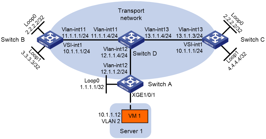
Configuration procedure
1. On VM 1, specify 10.1.1.1 as the gateway address. (Details not shown.)
2. Configure IP addresses and unicast routing settings:
# Assign IP addresses to interfaces, as shown in Figure 19. (Details not shown.)
# Configure OSPF on all transport network switches (Switches A through D). (Details not shown.)
3. Configure Switch A:
# Enable L2VPN.
<SwitchA> system-view
[SwitchA] l2vpn enable
# Create VSI vpna and VXLAN 10.
[SwitchA] vsi vpna
[SwitchA-vsi-vpna] vxlan 10
[SwitchA-vsi-vpna-vxlan-10] quit
[SwitchA-vsi-vpna] quit
# Assign an IP address to Loopback 0. The IP address will be used as the source IP address of the VXLAN tunnel to the VTEP group.
[SwitchA] interface loopback 0
[SwitchA-Loopback0] ip address 1.1.1.1 255.255.255.255
[SwitchA-Loopback0] quit
# Create a VXLAN tunnel to the VTEP group. The tunnel interface name is Tunnel 1.
[SwitchA] interface tunnel 1 mode vxlan
[SwitchA-Tunnel1] source 1.1.1.1
[SwitchA-Tunnel1] destination 2.2.2.2
[SwitchA-Tunnel1] quit
# Assign Tunnel 1 to VXLAN 10.
[SwitchA] vsi vpna
[SwitchA-vsi-vpna] vxlan 10
[SwitchA-vsi-vpna-vxlan-10] tunnel 1
[SwitchA-vsi-vpna-vxlan-10] quit
[SwitchA-vsi-vpna] quit
# On Ten-GigabitEthernet 1/0/1, create Ethernet service instance 1000 to match VLAN 2.
[SwitchA] interface ten-gigabitethernet 1/0/1
[SwitchA-Ten-GigabitEthernet1/0/1] service-instance 1000
[SwitchA-Ten-GigabitEthernet1/0/1-srv1000] encapsulation s-vid 2
# Map Ethernet service instance 1000 to VSI vpna.
[SwitchA-Ten-GigabitEthernet1/0/1-srv1000] xconnect vsi vpna
[SwitchA-Ten-GigabitEthernet1/0/1-srv1000] quit
[SwitchA-Ten-GigabitEthernet1/0/1] quit
# Specify VTEP group 2.2.2.2 and its member VTEPs at 3.3.3.3 and 4.4.4.4.
[SwitchA] vtep group 2.2.2.2 member remote 3.3.3.3 4.4.4.4
4. Configure Switch B:
# Enable L2VPN.
<SwitchB> system-view
[SwitchB] l2vpn enable
# Set the VXLAN hardware resource mode.
[SwitchB] hardware-resource vxlan l3gw8k
# Create VSI vpna and VXLAN 10.
[SwitchB] vsi vpna
[SwitchB-vsi-vpna] vxlan 10
[SwitchB-vsi-vpna-vxlan-10] quit
[SwitchB-vsi-vpna] quit
# Assign IP address 2.2.2.2/32 to Loopback 0. The IP address will be used as the IP address of the VTEP group.
[SwitchB] interface loopback 0
[SwitchB-Loopback0] ip address 2.2.2.2 255.255.255.255
[SwitchB-Loopback0] quit
# Assign an IP address to Loopback 1. The IP address will be used as the member IP address of the VTEP.
[SwitchB] interface loopback 1
[SwitchB-Loopback1] ip address 3.3.3.3 255.255.255.255
[SwitchB-Loopback1] quit
# Create a VXLAN tunnel to Switch A. The tunnel source IP address is 2.2.2.2, and the tunnel interface name is Tunnel 2.
[SwitchB] interface tunnel 2 mode vxlan
[SwitchB-Tunnel2] source 2.2.2.2
[SwitchB-Tunnel2] destination 1.1.1.1
[SwitchB-Tunnel2] quit
# Assign Tunnel 2 to VXLAN 10.
[SwitchB] vsi vpna
[SwitchB-vsi-vpna] vxlan 10
[SwitchB-vsi-vpna-vxlan-10] tunnel 2
[SwitchB-vsi-vpna-vxlan-10] quit
[SwitchB-vsi-vpna] quit
# Create VSI-interface 1 and assign the interface an IP address and a MAC address. The IP address will be used as the gateway address for VXLAN 10.
[SwitchB] interface vsi-interface 1
[SwitchB-Vsi-interface1] ip address 10.1.1.1 255.255.255.0
[SwitchB-Vsi-interface1] mac-address 2-2-2
[SwitchB-Vsi-interface1] quit
# Specify VSI-interface 1 as the gateway interface for VSI vpna.
[SwitchB] vsi vpna
[SwitchB-vsi-vpna] gateway vsi-interface 1
[SwitchB-vsi-vpna] quit
# Assign the local VTEP to VTEP group 2.2.2.2, and specify the member IP address of the local VTEP.
[SwitchB] vtep group 2.2.2.2 member local 3.3.3.3
# Specify the other member VTEP Switch C.
[SwitchB] vtep group 2.2.2.2 member remote 4.4.4.4
5. Configure Switch C:
# Enable L2VPN.
<SwitchC> system-view
[SwitchC] l2vpn enable
# Set the VXLAN hardware resource mode.
[SwitchC] hardware-resource vxlan l3gw8k
# Create VSI vpna and VXLAN 10.
[SwitchC] vsi vpna
[SwitchC-vsi-vpna] vxlan 10
[SwitchC-vsi-vpna-vxlan-10] quit
[SwitchC-vsi-vpna] quit
# Assign IP address 2.2.2.2/32 to Loopback 0. The IP address will be used as the IP address of the VTEP group.
[SwitchC] interface loopback 0
[SwitchC-Loopback0] ip address 2.2.2.2 255.255.255.255
[SwitchC-Loopback0] quit
# Assign an IP address to Loopback 1. The IP address will be used as the member IP address of the VTEP.
[SwitchC] interface loopback 1
[SwitchC-Loopback1] ip address 4.4.4.4 255.255.255.255
[SwitchC-Loopback1] quit
# Create a VXLAN tunnel to Switch A. The tunnel source IP address is 2.2.2.2, and the tunnel interface name is Tunnel 2.
[SwitchC] interface tunnel 2 mode vxlan
[SwitchC-Tunnel2] source 2.2.2.2
[SwitchC-Tunnel2] destination 1.1.1.1
[SwitchC-Tunnel2] quit
# Assign Tunnel 2 to VXLAN 10.
[SwitchC] vsi vpna
[SwitchC-vsi-vpna] vxlan 10
[SwitchC-vsi-vpna-vxlan-10] tunnel 2
[SwitchC-vsi-vpna-vxlan-10] quit
[SwitchC-vsi-vpna] quit
# Create VSI-interface 1 and assign the interface an IP address and a MAC address. The IP address will be used as the gateway address for VXLAN 10.
[SwitchC] interface vsi-interface 1
[SwitchC-Vsi-interface1] ip address 10.1.1.1 255.255.255.0
[SwitchC-Vsi-interface1] mac-address 2-2-2
[SwitchC-Vsi-interface1] quit
# Specify VSI-interface 1 as the gateway interface for VSI vpna.
[SwitchC] vsi vpna
[SwitchC-vsi-vpna] gateway vsi-interface 1
[SwitchC-vsi-vpna] quit
# Assign the local VTEP to VTEP group 2.2.2.2, and specify the member IP address of the local VTEP.
[SwitchC] vtep group 2.2.2.2 member local 4.4.4.4
# Specify the other member VTEP Switch B.
[SwitchC] vtep group 2.2.2.2 member remote 3.3.3.3
Distributed VXLAN IPv4 gateway configuration example
Network requirements
As shown in Figure 20:
· Configure VXLAN 10 and VXLAN 30 as unicast-mode VXLANs on Switch A, Switch B, and Switch C to provide connectivity for the VMs across the network sites.
· Manually establish VXLAN tunnels and assign the tunnels to the VXLANs.
· Configure distributed VXLAN IP gateways on Switch A and Switch C to forward traffic between the VXLANs.
· Configure Switch B as a border gateway to forward traffic between the VXLANs and the WAN connected to Switch E.
Figure 20 Network diagram
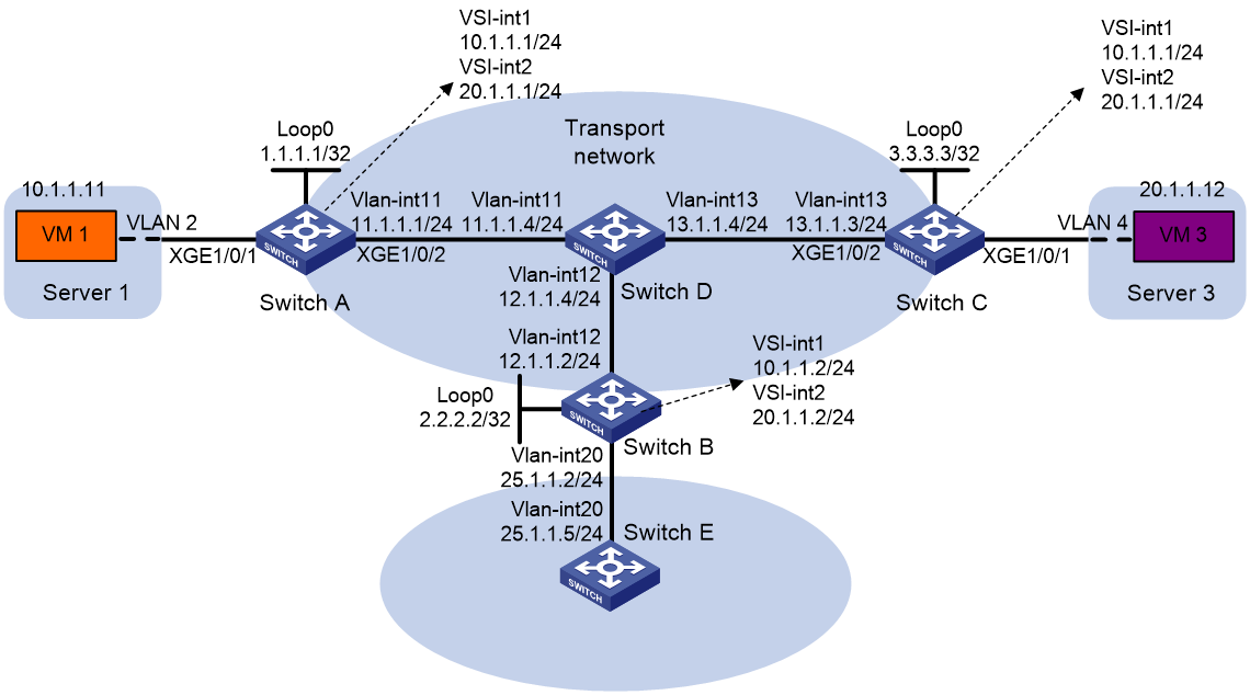
Configuration procedure
1. On VM 1 and VM 3, specify 10.1.1.1 and 20.1.1.1 as the gateway address, respectively. (Details not shown.)
2. Configure IP addresses and unicast routing settings:
# Assign IP addresses to interfaces, as shown in Figure 20. (Details not shown.)
# Configure OSPF on all transport network switches (Switches A through D). (Details not shown.)
# Configure OSPF to advertise routes to networks 10.1.1.0/24, 20.1.1.0/24, and 25.1.1.0/24 on Switch B and Switch E. (Details not shown.)
3. Configure Switch A:
# Enable L2VPN.
<SwitchA> system-view
[SwitchA] l2vpn enable
# Set the VXLAN hardware resource mode.
[SwitchA] hardware-resource vxlan l3gw8k
# Create VSI vpna and VXLAN 10.
[SwitchA] vsi vpna
[SwitchA-vsi-vpna] vxlan 10
[SwitchA-vsi-vpna-vxlan-10] quit
[SwitchA-vsi-vpna] quit
# Create VSI vpnc and VXLAN 30.
[SwitchA] vsi vpnc
[SwitchA-vsi-vpnc] vxlan 30
[SwitchA-vsi-vpnc-vxlan-30] quit
[SwitchA-vsi-vpnc] quit
# Assign an IP address to Loopback 0. The IP address will be used as the source IP address of the VXLAN tunnels to Switch B and Switch C.
[SwitchA] interface loopback 0
[SwitchA-Loopback0] ip address 1.1.1.1 255.255.255.255
[SwitchA-Loopback0] quit
# Create a VXLAN tunnel to Switch B. The tunnel interface name is Tunnel 1.
[SwitchA] interface tunnel 1 mode vxlan
[SwitchA-Tunnel1] source 1.1.1.1
[SwitchA-Tunnel1] destination 2.2.2.2
[SwitchA-Tunnel1] quit
# Create a VXLAN tunnel to Switch C. The tunnel interface name is Tunnel 2.
[SwitchA] interface tunnel 2 mode vxlan
[SwitchA-Tunnel2] source 1.1.1.1
[SwitchA-Tunnel2] destination 3.3.3.3
[SwitchA-Tunnel2] quit
# Assign Tunnel 1 and Tunnel 2 to VXLAN 10.
[SwitchA] vsi vpna
[SwitchA-vsi-vpna] vxlan 10
[SwitchA-vsi-vpna-vxlan-10] tunnel 1
[SwitchA-vsi-vpna-vxlan-10] tunnel 2
[SwitchA-vsi-vpna-vxlan-10] quit
[SwitchA-vsi-vpna] quit
# Assign Tunnel 1 and Tunnel 2 to VXLAN 30.
[SwitchA] vsi vpnc
[SwitchA-vsi-vpnc] vxlan 30
[SwitchA-vsi-vpnc-vxlan-30] tunnel 1
[SwitchA-vsi-vpnc-vxlan-30] tunnel 2
[SwitchA-vsi-vpnc-vxlan-30] quit
[SwitchA-vsi-vpnc] quit
# On Ten-GigabitEthernet 1/0/1, create Ethernet service instance 1000 to match VLAN 2.
[SwitchA] interface ten-gigabitethernet 1/0/1
[SwitchA-Ten-GigabitEthernet1/0/1] service-instance 1000
[SwitchA-Ten-GigabitEthernet1/0/1-srv1000] encapsulation s-vid 2
# Map Ethernet service instance 1000 to VSI vpna.
[SwitchA-Ten-GigabitEthernet1/0/1-srv1000] xconnect vsi vpna
[SwitchA-Ten-GigabitEthernet1/0/1-srv1000] quit
[SwitchA-Ten-GigabitEthernet1/0/1] quit
# Create VSI-interface 1 and assign the interface an IP address and a MAC address. The IP address will be used as the gateway address for VXLAN 10.
[SwitchA] interface vsi-interface 1
[SwitchA-Vsi-interface1] ip address 10.1.1.1 255.255.255.0
[SwitchA-Vsi-interface1] mac-address 1-1-1
# Specify VSI-interface 1 as a distributed gateway and enable local proxy ARP on the interface.
[SwitchA-Vsi-interface1] distributed-gateway local
[SwitchA-Vsi-interface1] local-proxy-arp enable
[SwitchA-Vsi-interface1] quit
# Create VSI-interface 2 and assign the interface an IP address and a MAC address. The IP address will be used as the gateway address for VXLAN 30.
[SwitchA] interface vsi-interface 2
[SwitchA-Vsi-interface2] ip address 20.1.1.1 255.255.255.0
[SwitchA-Vsi-interface2] mac-address 2-2-2
# Specify VSI-interface 2 as a distributed gateway and enable local proxy ARP on the interface.
[SwitchA-Vsi-interface2] distributed-gateway local
[SwitchA-Vsi-interface2] local-proxy-arp enable
[SwitchA-Vsi-interface2] quit
# Disable source MAC check on transport-facing interface Ten-GigabitEthernet 1/0/2.
[SwitchA] interface ten-gigabitethernet 1/0/2
[SwitchA-Ten-GigabitEthernet1/0/2] undo mac-address static source-check enable
# Enable dynamic ARP entry synchronization for distributed VXLAN IP gateways.
[SwitchA] arp distributed-gateway dynamic-entry synchronize
# Specify VSI-interface 1 as the gateway interface for VSI vpna.
[SwitchA] vsi vpna
[SwitchA-vsi-vpna] gateway vsi-interface 1
[SwitchA-vsi-vpna] quit
# Specify VSI-interface 2 as the gateway interface for VSI vpnc.
[SwitchA] vsi vpnc
[SwitchA-vsi-vpnc] gateway vsi-interface 2
[SwitchA-vsi-vpnc] quit
# Configure a PBR policy for VXLAN 10. Set the policy name to vxlan10, and set the next hop to 10.1.1.2 (VSI-interface 1 on Switch B).
[SwitchA] acl advanced 3000
[SwitchA-acl-ipv4-adv-3000] rule 0 permit ip
[SwitchA-acl-ipv4-adv-3000] quit
[SwitchA] policy-based-route vxlan10 permit node 5
[SwitchA-pbr-vxlan10-5] if-match acl 3000
[SwitchA-pbr-vxlan10-5] apply next-hop 10.1.1.2
[SwitchA-pbr-vxlan10-5] quit
# Configure a PBR policy for VXLAN 30. Set the policy name to vxlan30, and set the next hop to 20.1.1.2 (VSI-interface 2 on Switch B).
[SwitchA] policy-based-route vxlan30 permit node 5
[SwitchA-pbr-vxlan30-5] if-match acl 3000
[SwitchA-pbr-vxlan30-5] apply next-hop 20.1.1.2
[SwitchA-pbr-vxlan30-5] quit
# Apply policies vxlan10 and vxlan30 to VSI-interface 1 and VSI-interface 2, respectively.
[SwitchA] interface vsi-interface 1
[SwitchA-Vsi-interface1] ip policy-based-route vxlan10
[SwitchA-Vsi-interface1] quit
[SwitchA] interface vsi-interface 2
[SwitchA-Vsi-interface2] ip policy-based-route vxlan30
[SwitchA-Vsi-interface2] quit
4. Configure Switch B:
# Enable L2VPN.
<SwitchB> system-view
[SwitchB] l2vpn enable
# Set the VXLAN hardware resource mode.
[SwitchB] hardware-resource vxlan border8k
# Create VSI vpna and VXLAN 10.
[SwitchB] vsi vpna
[SwitchB-vsi-vpna] vxlan 10
[SwitchB-vsi-vpna-vxlan-10] quit
[SwitchB-vsi-vpna] quit
# Create VSI vpnc and VXLAN 30.
[SwitchB] vsi vpnc
[SwitchB-vsi-vpnc] vxlan 30
[SwitchB-vsi-vpnc-vxlan-30] quit
[SwitchB-vsi-vpnc] quit
# Assign an IP address to Loopback 0. The IP address will be used as the source IP address of the VXLAN tunnels to Switch A and Switch C.
[SwitchB] interface loopback 0
[SwitchB-Loopback0] ip address 2.2.2.2 255.255.255.255
[SwitchB-Loopback0] quit
# Create a VXLAN tunnel to Switch A. The tunnel interface name is Tunnel 2.
[SwitchB] interface tunnel 2 mode vxlan
[SwitchB-Tunnel2] source 2.2.2.2
[SwitchB-Tunnel2] destination 1.1.1.1
[SwitchB-Tunnel2] quit
# Create a VXLAN tunnel to Switch C. The tunnel interface name is Tunnel 3.
[SwitchB] interface tunnel 3 mode vxlan
[SwitchB-Tunnel3] source 2.2.2.2
[SwitchB-Tunnel3] destination 3.3.3.3
[SwitchB-Tunnel3] quit
# Assign Tunnel 2 to VXLAN 10.
[SwitchB] vsi vpna
[SwitchB-vsi-vpna] vxlan 10
[SwitchB-vsi-vpna-vxlan-10] tunnel 2
[SwitchB-vsi-vpna-vxlan-10] quit
[SwitchB-vsi-vpna] quit
# Assign Tunnel 3 to VXLAN 30.
[SwitchB] vsi vpnc
[SwitchB-vsi-vpnc] vxlan 30
[SwitchB-vsi-vpnc-vxlan-30] tunnel 3
[SwitchB-vsi-vpnc-vxlan-30] quit
[SwitchB-vsi-vpnc] quit
# Create VSI-interface 1 and assign the interface an IP address.
[SwitchB] interface vsi-interface 1
[SwitchB-Vsi-interface1] ip address 10.1.1.2 255.255.255.0
[SwitchB-Vsi-interface1] quit
# Create VSI-interface 2 and assign the interface an IP address.
[SwitchB] interface vsi-interface 2
[SwitchB-Vsi-interface2] ip address 20.1.1.2 255.255.255.0
[SwitchB-Vsi-interface2] quit
# Specify VSI-interface 1 as the gateway interface for VSI vpna.
[SwitchB] vsi vpna
[SwitchB-vsi-vpna] gateway vsi-interface 1
[SwitchB-vsi-vpna] quit
# Specify VSI-interface 2 as the gateway interface for VSI vpnc.
[SwitchB] vsi vpnc
[SwitchB-vsi-vpnc] gateway vsi-interface 2
[SwitchB-vsi-vpnc] quit
5. Configure Switch C:
# Enable L2VPN.
<SwitchC> system-view
[SwitchC] l2vpn enable
# Set the VXLAN hardware resource mode.
[SwitchC] hardware-resource vxlan l3gw8k
# Create VSI vpna and VXLAN 10.
[SwitchC] vsi vpna
[SwitchC-vsi-vpna] vxlan 10
[SwitchC-vsi-vpna-vxlan-10] quit
[SwitchC-vsi-vpna] quit
# Create VSI vpnb and VXLAN 30.
[SwitchC] vsi vpnb
[SwitchC-vsi-vpnb] vxlan 30
[SwitchC-vsi-vpnb-vxlan-30] quit
[SwitchC-vsi-vpnb] quit
# Assign an IP address to Loopback 0. The IP address will be used as the source IP address of the VXLAN tunnels to Switch A and Switch B.
[SwitchC] interface loopback 0
[SwitchC-Loopback0] ip address 3.3.3.3 255.255.255.255
[SwitchC-Loopback0] quit
# Create a VXLAN tunnel to Switch A. The tunnel interface name is Tunnel 1.
[SwitchC] interface tunnel 1 mode vxlan
[SwitchC-Tunnel1] source 3.3.3.3
[SwitchC-Tunnel1] destination 1.1.1.1
[SwitchC-Tunnel1] quit
# Create a VXLAN tunnel to Switch B. The tunnel interface name is Tunnel 3.
[SwitchC] interface tunnel 3 mode vxlan
[SwitchC-Tunnel3] source 3.3.3.3
[SwitchC-Tunnel3] destination 2.2.2.2
[SwitchC-Tunnel3] quit
# Assign Tunnel 1 and Tunnel 3 to VXLAN 10.
[SwitchC] vsi vpna
[SwitchC-vsi-vpna] vxlan 10
[SwitchC-vsi-vpna-vxlan-10] tunnel 1
[SwitchC-vsi-vpna-vxlan-10] tunnel 3
[SwitchC-vsi-vpna-vxlan-10] quit
[SwitchC-vsi-vpna] quit
# Assign Tunnel 1 and Tunnel 3 to VXLAN 30.
[SwitchC] vsi vpnb
[SwitchC-vsi-vpnb] vxlan 30
[SwitchC-vsi-vpnb-vxlan-30] tunnel 1
[SwitchC-vsi-vpnb-vxlan-30] tunnel 3
[SwitchC-vsi-vpnb-vxlan-30] quit
[SwitchC-vsi-vpnb] quit
# On Ten-GigabitEthernet 1/0/1, create Ethernet service instance 1000 to match VLAN 4.
[SwitchC] interface ten-gigabitethernet 1/0/1
[SwitchC-Ten-GigabitEthernet1/0/1] service-instance 1000
[SwitchC-Ten-GigabitEthernet1/0/1-srv1000] encapsulation s-vid 4
# Map Ethernet service instance 1000 to VSI vpnb.
[SwitchC-Ten-GigabitEthernet1/0/1-srv1000] xconnect vsi vpnb
[SwitchC-Ten-GigabitEthernet1/0/1-srv1000] quit
[SwitchC-Ten-GigabitEthernet1/0/1] quit
# Create VSI-interface 1 and assign the interface an IP address and a MAC address. The IP address will be used as the gateway address for VXLAN 10.
[SwitchC] interface vsi-interface 1
[SwitchC-Vsi-interface1] ip address 10.1.1.1 255.255.255.0
[SwitchC-Vsi-interface1] mac-address 1-1-1
# Specify VSI-interface 1 as a distributed gateway and enable local proxy ARP on the interface.
[SwitchC-Vsi-interface1] distributed-gateway local
[SwitchC-Vsi-interface1] local-proxy-arp enable
[SwitchC-Vsi-interface1] quit
# Disable source MAC check on transport-facing interface Ten-GigabitEthernet 1/0/2.
[SwitchC] interface ten-gigabitethernet 1/0/2
[SwitchC-Ten-GigabitEthernet1/0/2] undo mac-address static source-check enable
# Enable dynamic ARP entry synchronization for distributed VXLAN IP gateways.
[SwitchC] arp distributed-gateway dynamic-entry synchronize
# Specify VSI-interface 1 as the gateway interface for VSI vpna.
[SwitchC] vsi vpna
[SwitchC-vsi-vpna] gateway vsi-interface 1
[SwitchC-vsi-vpna] quit
# Create VSI-interface 2 and assign the interface an IP address and a MAC address. The IP address will be used as the gateway address for VXLAN 30.
[SwitchC] interface vsi-interface 2
[SwitchC-Vsi-interface2] ip address 20.1.1.1 255.255.255.0
[SwitchC-Vsi-interface2] mac-address 2-2-2
# Specify VSI-interface 2 as a distributed gateway and enable local proxy ARP on the interface.
[SwitchC-Vsi-interface2] distributed-gateway local
[SwitchC-Vsi-interface2] local-proxy-arp enable
[SwitchC-Vsi-interface2] quit
# Specify VSI-interface 2 as the gateway interface for VSI vpnb.
[SwitchC] vsi vpnb
[SwitchC-vsi-vpnb] gateway vsi-interface 2
[SwitchC-vsi-vpnb] quit
# Configure a PBR policy for the VXLANs. Set the policy name to vxlan and set the next hop to 20.1.1.2 (VSI-interface 1 on Switch B).
[SwitchC] acl advanced 3000
[SwitchC-acl-ipv4-adv-3000] rule 0 permit ip
[SwitchC-acl-ipv4-adv-3000] quit
[SwitchC] policy-based-route vxlan permit node 5
[SwitchC-pbr-vxlan-5] if-match acl 3000
[SwitchC-pbr-vxlan-5] apply next-hop 20.1.1.2
[SwitchC-pbr-vxlan-5] quit
# Apply policy vxlan to VSI-interface 2.
[SwitchC] interface vsi-interface 2
[SwitchC-Vsi-interface2] ip policy-based-route vxlan
[SwitchC-Vsi-interface2] quit
Verifying the configuration
1. Verify the VXLAN IP gateway settings on Switch A:
# Verify that the VXLAN tunnel interfaces are up on Switch A.
[SwitchA] display interface tunnel 2
Tunnel2
Current state: UP
Line protocol state: UP
Description: Tunnel2 Interface
Bandwidth: 64 kbps
Maximum transmission unit: 1464
Internet protocol processing: Disabled
Last clearing of counters: Never
Tunnel source 1.1.1.1, destination 3.3.3.3
Tunnel protocol/transport UDP_VXLAN/IP
Last 300 seconds input rate: 0 bytes/sec, 0 bits/sec, 0 packets/sec
Last 300 seconds output rate: 0 bytes/sec, 0 bits/sec, 0 packets/sec
Input: 0 packets, 0 bytes, 0 drops
Output: 0 packets, 0 bytes, 0 drops
# Verify that VSI-interface 1 is up.
[SwitchA] display interface vsi-interface 1
Vsi-interface1
Current state: UP
Line protocol state: UP
Description: Vsi-interface1 Interface
Bandwidth: 1000000 kbps
Maximum transmission unit: 1444
Internet address: 10.1.1.1/24 (primary)
IP packet frame type: Ethernet II, hardware address: 0001-0001-0001
IPv6 packet frame type: Ethernet II, hardware address: 0001-0001-0001
Physical: Unknown, baudrate: 1000000 kbps
Last clearing of counters: Never
Input (total): 0 packets, 0 bytes
Output (total): 0 packets, 0 bytes
# Verify that the VXLAN tunnels have been assigned to VXLAN 10, and VSI-interface 1 is the gateway interface for VSI vpna.
[SwitchA] display l2vpn vsi name vpna verbose
VSI Name: vpna
VSI Index : 0
VSI State : Up
MTU : 1500
Bandwidth : Unlimited
Broadcast Restrain : Unlimited
Multicast Restrain : Unlimited
Unknown Unicast Restrain: Unlimited
MAC Learning : Enabled
MAC Table Limit : -
MAC Learning rate : -
Drop Unknown : -
Flooding : Enabled
Statistics : Disabled
Gateway Interface : VSI-interface 1
VXLAN ID : 10
Tunnels:
Tunnel Name Link ID State Type Flood proxy
Tunnel1 0x5000001 Up Manual Disabled
Tunnel2 0x5000002 Up Manual Disabled
ACs:
AC Link ID State Type
XGE1/0/1 srv1000 0 Up Manual
# Verify that Switch A has created ARP entries for the VMs.
[SwitchA] display arp
Type: S-Static D-Dynamic O-Openflow R-Rule M-Multiport I-Invalid
IP address MAC address VLAN/VSI Interface/Link ID Aging Type
11.1.1.4 000c-29c1-5e46 11 Vlan11 19 D
10.1.1.2 0003-0000-0000 N/A Vsi1 20 D
10.1.1.11 0cda-41b5-cf09 N/A Vsi1 20 D
20.1.1.12 0000-fc00-0b01 N/A Vsi2 19 D
2. Verify the configuration on the border gateway Switch B:
# Verify that the VXLAN tunnel interfaces are up on Switch B.
[SwitchB] display interface tunnel 2
Tunnel2
Current state: UP
Line protocol state: UP
Description: Tunnel2 Interface
Bandwidth: 64 kbps
Maximum transmission unit: 1464
Internet protocol processing: Disabled
Last clearing of counters: Never
Tunnel source 2.2.2.2, destination 1.1.1.1
Tunnel protocol/transport UDP_VXLAN/IP
Last 300 seconds input rate: 0 bytes/sec, 0 bits/sec, 0 packets/sec
Last 300 seconds output rate: 0 bytes/sec, 0 bits/sec, 0 packets/sec
Input: 0 packets, 0 bytes, 0 drops
Output: 0 packets, 0 bytes, 0 drops
# Verify that VSI-interface 1 is up.
[SwitchB] display interface vsi-interface 1
Vsi-interface1
Current state: UP
Line protocol state: UP
Description: Vsi-interface1 Interface
Bandwidth: 1000000 kbps
Maximum transmission unit: 1444
Internet address: 10.1.1.2/24 (primary)
IP packet frame type: Ethernet II, hardware address: 0011-2200-0102
IPv6 packet frame type: Ethernet II, hardware address: 0011-2200-0102
Physical: Unknown, baudrate: 1000000 kbps
Last clearing of counters: Never
Input (total): 0 packets, 0 bytes
Output (total): 0 packets, 0 bytes
# Verify that the VXLAN tunnels have been assigned to VXLAN 10, and VSI-interface 1 is the gateway interface for VSI vpna.
[SwitchB] display l2vpn vsi name vpna verbose
VSI Name: vpna
VSI Index : 0
VSI State : Up
MTU : 1500
Bandwidth : Unlimited
Broadcast Restrain : Unlimited
Multicast Restrain : Unlimited
Unknown Unicast Restrain: Unlimited
MAC Learning : Enabled
MAC Table Limit : -
MAC Learning rate : -
Drop Unknown : -
Flooding : Enabled
Statistics : Disabled
Gateway interface : VSI-interface 1
VXLAN ID : 10
Tunnels:
Tunnel Name Link ID State Type Flood proxy
Tunnel2 0x5000002 Up Manual Disabled
# Verify that Switch B has created ARP entries for the VMs.
[SwitchB] display arp
Type: S-Static D-Dynamic O-Openflow R-Rule M-Multiport I-Invalid
IP address MAC address VLAN/VSI Interface/Link ID Aging Type
12.1.1.4 0000-fc00-00ab 12 Vlan12 14 D
25.1.1.5 4431-9234-24bb 20 Vlan20 17 D
10.1.1.1 0000-fc00-00ab N/A Vsi1 17 D
10.1.1.11 0000-fc00-00ab N/A Vsi1 20 D
20.1.1.1 0000-fc00-00aa N/A Vsi3 17 D
20.1.1.12 0000-fc00-00aa N/A Vsi3 20 D
# Verify that Switch B has created FIB entries for the VMs.
[SwitchB] display fib 10.1.1.11
Destination count: 1 FIB entry count: 1
Flag:
U:Useable G:Gateway H:Host B:Blackhole D:Dynamic S:Static
R:Relay F:FRR
Destination/Mask Nexthop Flag OutInterface/Token Label
10.1.1.11/32 10.1.1.11 UH Vsi1 Null
[SwitchB] display fib 20.1.1.12
Destination count: 1 FIB entry count: 1
Flag:
U:Useable G:Gateway H:Host B:Blackhole D:Dynamic S:Static
R:Relay F:FRR
Destination/Mask Nexthop Flag OutInterface/Token Label
20.1.1.12/32 20.1.1.12 UH Vsi1 Null
3. Verify that the network connectivity for VMs meets the requirements:
# Verify that VM 1 and VM 3 can ping each other. (Details not shown.)
# Verify that VM 1 and VM 3 can ping VLAN-interface 20 (25.1.1.5) on Switch E for WAN access. (Details not shown.)
Distributed VXLAN IPv6 gateway configuration example
Network requirements
As shown in Figure 21:
· Configure VXLAN 10 and VXLAN 20 as unicast-mode VXLANs on Switch A, Switch B, and Switch C to provide connectivity for the VMs across the network sites.
· Manually establish VXLAN tunnels and assign the tunnels to the VXLANs.
· Configure distributed VXLAN IP gateways on Switch A and Switch C to forward traffic between the VXLANs.
· Configure Switch B as a border gateway to forward traffic between the VXLANs and the WAN connected to Switch E.
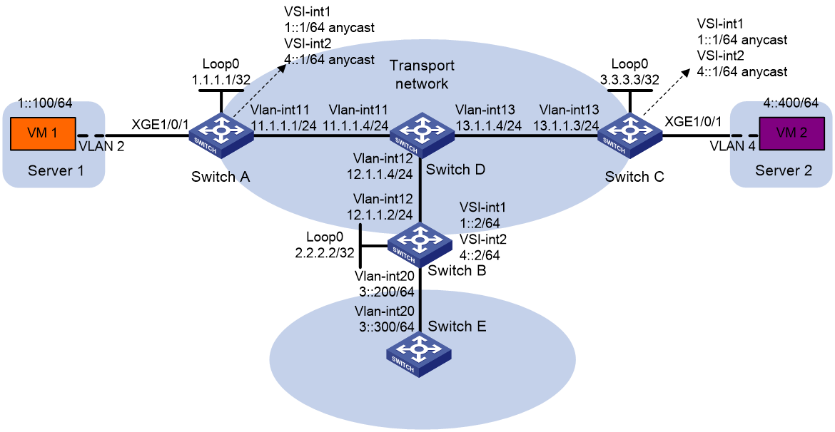
Configuration procedure
1. On VM 1 and VM 2, specify 1::1 and 4::1 as the gateway address, respectively. (Details not shown.)
2. Configure IP addresses and unicast routing settings:
# Assign IP addresses to interfaces, as shown in Figure 21. (Details not shown.)
# Configure OSPF on all transport network switches (switches A through D). (Details not shown.)
# Configure OSPFv3 to advertise routes to networks 1::/64, 4::/64, and 3::/64 on Switch B and Switch E. (Details not shown.)
3. Configure Switch A:
# Enable L2VPN.
<SwitchA> system-view
[SwitchA] l2vpn enable
# Set the VXLAN hardware resource mode.
[SwitchA] hardware-resource vxlan l3gw8k
# Create VSI vpna and VXLAN 10.
[SwitchA] vsi vpna
[SwitchA-vsi-vpna] vxlan 10
[SwitchA-vsi-vpna-vxlan-10] quit
[SwitchA-vsi-vpna] quit
# Create VSI vpnb and VXLAN 20.
[SwitchA] vsi vpnb
[SwitchA-vsi-vpnb] vxlan 20
[SwitchA-vsi-vpnb-vxlan-20] quit
[SwitchA-vsi-vpnb] quit
# Assign an IP address to Loopback 0. The IP address will be used as the source IP address of the VXLAN tunnels to Switch B and Switch C.
[SwitchA] interface loopback 0
[SwitchA-Loopback0] ip address 1.1.1.1 255.255.255.255
[SwitchA-Loopback0] quit
# Create a VXLAN tunnel to Switch B. The tunnel interface name is Tunnel 1.
[SwitchA] interface tunnel 1 mode vxlan
[SwitchA-Tunnel1] source 1.1.1.1
[SwitchA-Tunnel1] destination 2.2.2.2
[SwitchA-Tunnel1] quit
# Create a VXLAN tunnel to Switch C. The tunnel interface name is Tunnel 2.
[SwitchA] interface tunnel 2 mode vxlan
[SwitchA-Tunnel2] source 1.1.1.1
[SwitchA-Tunnel2] destination 3.3.3.3
[SwitchA-Tunnel2] quit
# Assign Tunnel 1 and Tunnel 2 to VXLAN 10.
[SwitchA] vsi vpna
[SwitchA-vsi-vpna] vxlan 10
[SwitchA-vsi-vpna-vxlan-10] tunnel 1
[SwitchA-vsi-vpna-vxlan-10] tunnel 2
[SwitchA-vsi-vpna-vxlan-10] quit
[SwitchA-vsi-vpna] quit
# Assign Tunnel 1 and Tunnel 2 to VXLAN 20.
[SwitchA] vsi vpnb
[SwitchA-vsi-vpnb] vxlan 20
[SwitchA-vsi-vpnb-vxlan-20] tunnel 1
[SwitchA-vsi-vpnb-vxlan-20] tunnel 2
[SwitchA-vsi-vpnb-vxlan-20] quit
[SwitchA-vsi-vpnb] quit
# On Ten-GigabitEthernet 1/0/1, create Ethernet service instance 1000 to match VLAN 2.
[SwitchA] interface ten-gigabitethernet 1/0/1
[SwitchA-Ten-GigabitEthernet1/0/1] service-instance 1000
[SwitchA-Ten-GigabitEthernet1/0/1-srv1000] encapsulation s-vid 2
# Map Ethernet service instance 1000 to VSI vpna.
[SwitchA-Ten-GigabitEthernet1/0/1-srv1000] xconnect vsi vpna
[SwitchA-Ten-GigabitEthernet1/0/1-srv1000] quit
[SwitchA-Ten-GigabitEthernet1/0/1] quit
# Enable dynamic ND entry synchronization for distributed VXLAN IP gateways.
[SwitchA] ipv6 nd distributed-gateway dynamic-entry synchronize
# Create VSI-interface 1 and assign the interface an IPv6 anycast address. The IP address will be used as the gateway address for VXLAN 10.
[SwitchA] interface vsi-interface 1
[SwitchA-Vsi-interface1] ipv6 address 1::1/64 anycast
# Specify VSI-interface 1 as a distributed gateway and enable local ND proxy on the interface.
[SwitchA-Vsi-interface1] distributed-gateway local
[SwitchA-Vsi-interface1] local-proxy-nd enable
[SwitchA-Vsi-interface1] quit
# Specify VSI-interface 1 as the gateway interface for VSI vpna.
[SwitchA] vsi vpna
[SwitchA-vsi-vpna] gateway vsi-interface 1
[SwitchA-vsi-vpna] quit
# Create VSI-interface 2 and assign the interface an IPv6 anycast address. The IP address will be used as the gateway address for VXLAN 20.
[SwitchA] interface vsi-interface 2
[SwitchA-Vsi-interface2] ipv6 address 4::1/64 anycast
# Specify VSI-interface 2 as a distributed gateway and enable local ND proxy on the interface.
[SwitchA-Vsi-interface2] distributed-gateway local
[SwitchA-Vsi-interface2] local-proxy-nd enable
[SwitchA-Vsi-interface2] quit
# Specify VSI-interface 2 as the gateway interface for VSI vpnb.
[SwitchA] vsi vpnb
[SwitchA-vsi-vpnb] gateway vsi-interface 2
[SwitchA-vsi-vpnb] quit
# Configure an IPv6 static route. Set the destination address to 3::/64 and the next hop to 1::2.
[SwitchA] ipv6 route-static 3:: 64 1::2
4. Configure Switch B:
# Enable L2VPN.
<SwitchB> system-view
[SwitchB] l2vpn enable
# Set the VXLAN hardware resource mode.
[SwitchB] hardware-resource vxlan border8k
# Create VSI vpna and VXLAN 10.
[SwitchB] vsi vpna
[SwitchB-vsi-vpna] vxlan 10
[SwitchB-vsi-vpna-vxlan-10] quit
[SwitchB-vsi-vpna] quit
# Create VSI vpnb and VXLAN 20.
[SwitchB] vsi vpnb
[SwitchB-vsi-vpnb] vxlan 20
[SwitchB-vsi-vpnb-vxlan-20] quit
[SwitchB-vsi-vpnb] quit
# Assign an IP address to Loopback 0. The IP address will be used as the source IP address of the VXLAN tunnels to Switch A and Switch C.
[SwitchB] interface loopback 0
[SwitchB-Loopback0] ip address 2.2.2.2 255.255.255.255
[SwitchB-Loopback0] quit
# Create a VXLAN tunnel to Switch A. The tunnel interface name is Tunnel 2.
[SwitchB] interface tunnel 2 mode vxlan
[SwitchB-Tunnel2] source 2.2.2.2
[SwitchB-Tunnel2] destination 1.1.1.1
[SwitchB-Tunnel2] quit
# Create a VXLAN tunnel to Switch C. The tunnel interface name is Tunnel 3.
[SwitchB] interface tunnel 3 mode vxlan
[SwitchB-Tunnel3] source 2.2.2.2
[SwitchB-Tunnel3] destination 3.3.3.3
[SwitchB-Tunnel3] quit
# Assign Tunnel 2 and Tunnel 3 to VXLAN 10.
[SwitchB] vsi vpna
[SwitchB-vsi-vpna] vxlan 10
[SwitchB-vsi-vpna-vxlan-10] tunnel 2
[SwitchB-vsi-vpna-vxlan-10] tunnel 3
[SwitchB-vsi-vpna-vxlan-10] quit
[SwitchB-vsi-vpna] quit
# Assign Tunnel 2 and Tunnel 3 to VXLAN 20.
[SwitchB] vsi vpnb
[SwitchB-vsi-vpnb] vxlan 20
[SwitchB-vsi-vpnb-vxlan-20] tunnel 2
[SwitchB-vsi-vpnb-vxlan-20] tunnel 3
[SwitchB-vsi-vpnb-vxlan-20] quit
[SwitchB-vsi-vpnb] quit
# Create VSI-interface 1 and assign the interface an IPv6 address.
[SwitchB] interface vsi-interface 1
[SwitchB-Vsi-interface1] ipv6 address 1::2/64
[SwitchB-Vsi-interface1] quit
# Create VSI-interface 2 and assign the interface an IPv6 address.
[SwitchB] interface vsi-interface 2
[SwitchB-Vsi-interface2] ipv6 address 4::2/64
[SwitchB-Vsi-interface2] quit
# Specify VSI-interface 1 as the gateway interface for VSI vpna.
[SwitchB] vsi vpna
[SwitchB-vsi-vpna] gateway vsi-interface 1
[SwitchB-vsi-vpna] quit
# Specify VSI-interface 2 as the gateway interface for VSI vpnb.
[SwitchB] vsi vpnb
[SwitchB-vsi-vpnb] gateway vsi-interface 2
[SwitchB-vsi-vpnb] quit
5. Configure Switch C:
# Enable L2VPN.
<SwitchC> system-view
[SwitchC] l2vpn enable
# Set the VXLAN hardware resource mode.
[SwitchC] hardware-resource vxlan l3gw8k
# Create VSI vpna and VXLAN 10.
[SwitchC] vsi vpna
[SwitchC-vsi-vpna] vxlan 10
[SwitchC-vsi-vpna-vxlan-10] quit
[SwitchC-vsi-vpna] quit
# Create VSI vpnb and VXLAN 20.
[SwitchC] vsi vpnb
[SwitchC-vsi-vpnb] vxlan 20
[SwitchC-vsi-vpnb-vxlan-20] quit
[SwitchC-vsi-vpnb] quit
# Assign an IP address to Loopback 0. The IP address will be used as the source IP address of the VXLAN tunnels to Switch A and Switch B.
[SwitchC] interface loopback 0
[SwitchC-Loopback0] ip address 3.3.3.3 255.255.255.255
[SwitchC-Loopback0] quit
# Create a VXLAN tunnel to Switch A. The tunnel interface name is Tunnel 1.
[SwitchC] interface tunnel 1 mode vxlan
[SwitchC-Tunnel1] source 3.3.3.3
[SwitchC-Tunnel1] destination 1.1.1.1
[SwitchC-Tunnel1] quit
# Create a VXLAN tunnel to Switch B. The tunnel interface name is Tunnel 3.
[SwitchC] interface tunnel 3 mode vxlan
[SwitchC-Tunnel3] source 3.3.3.3
[SwitchC-Tunnel3] destination 2.2.2.2
[SwitchC-Tunnel3] quit
# Assign Tunnel 1 and Tunnel 3 to VXLAN 10.
[SwitchC] vsi vpna
[SwitchC-vsi-vpna] vxlan 10
[SwitchC-vsi-vpna-vxlan-10] tunnel 1
[SwitchC-vsi-vpna-vxlan-10] tunnel 3
[SwitchC-vsi-vpna-vxlan-10] quit
[SwitchC-vsi-vpna] quit
# Assign Tunnel 1 and Tunnel 3 to VXLAN 20.
[SwitchC] vsi vpnb
[SwitchC-vsi-vpnb] vxlan 20
[SwitchC-vsi-vpnb-vxlan-20] tunnel 1
[SwitchC-vsi-vpnb-vxlan-20] tunnel 3
[SwitchC-vsi-vpnb-vxlan-20] quit
[SwitchC-vsi-vpnb] quit
# On Ten-GigabitEthernet 1/0/1, create Ethernet service instance 1000 to match VLAN 4.
[SwitchC] interface ten-gigabitethernet 1/0/1
[SwitchC-Ten-GigabitEthernet1/0/1] service-instance 1000
[SwitchC-Ten-GigabitEthernet1/0/1-srv1000] encapsulation s-vid 4
# Map Ethernet service instance 1000 to VSI vpnb.
[SwitchC-Ten-GigabitEthernet1/0/1-srv1000] xconnect vsi vpnb
[SwitchC-Ten-GigabitEthernet1/0/1-srv1000] quit
[SwitchC-Ten-GigabitEthernet1/0/1] quit
# Enable dynamic ND entry synchronization for distributed VXLAN IP gateways.
[SwitchC] ipv6 nd distributed-gateway dynamic-entry synchronize
# Create VSI-interface 1 and assign the interface an IPv6 anycast address. The IP address will be used as the gateway address for VXLAN 10.
[SwitchC] interface vsi-interface 1
[SwitchC-Vsi-interface1] ipv6 address 1::1/64 anycast
# Specify VSI-interface 1 as a distributed gateway and enable local ND proxy on the interface.
[SwitchC-Vsi-interface1] distributed-gateway local
[SwitchC-Vsi-interface1] local-proxy-nd enable
[SwitchC-Vsi-interface1] quit
# Specify VSI-interface 1 as the gateway interface for VSI vpna.
[SwitchC] vsi vpna
[SwitchC-vsi-vpna] gateway vsi-interface 1
[SwitchC-vsi-vpna] quit
# Create VSI-interface 2 and assign the interface an IPv6 anycast address. The IP address will be used as the gateway address for VXLAN 20.
[SwitchC] interface vsi-interface 2
[SwitchC-Vsi-interface2] ipv6 address 4::1/64 anycast
# Specify VSI-interface 2 as a distributed gateway and enable local ND proxy on the interface.
[SwitchC-Vsi-interface2] distributed-gateway local
[SwitchC-Vsi-interface2] local-proxy-nd enable
[SwitchC-Vsi-interface2] quit
# Specify VSI-interface 2 as the gateway interface for VSI vpnb.
[SwitchC] vsi vpnb
[SwitchC-vsi-vpnb] gateway vsi-interface 2
[SwitchC-vsi-vpnb] quit
# Configure an IPv6 static route. Set the destination address to 3::/64 and the next hop to 4::2.
[SwitchC] ipv6 route-static 3:: 64 4::2
Verifying the configuration
1. Verify the distributed VXLAN IP gateway settings on Switch A:
# Verify that the VXLAN tunnel interfaces are up on Switch A.
[SwitchA] display interface tunnel 2
Tunnel2
Current state: UP
Line protocol state: UP
Description: Tunnel2 Interface
Bandwidth: 64 kbps
Maximum transmission unit: 1464
Internet protocol processing: Disabled
Last clearing of counters: Never
Tunnel source 1.1.1.1, destination 3.3.3.3
Tunnel protocol/transport UDP_VXLAN/IP
Last 300 seconds input rate: 0 bytes/sec, 0 bits/sec, 0 packets/sec
Last 300 seconds output rate: 0 bytes/sec, 0 bits/sec, 0 packets/sec
Input: 0 packets, 0 bytes, 0 drops
Output: 0 packets, 0 bytes, 0 drops
# Verify that the VSI interfaces are up.
[SwitchA] display interface vsi-interface 1
Vsi-interface1
Current state: UP
Line protocol state: UP
Description: Vsi-interface1 Interface
Bandwidth: 1000000 kbps
Maximum transmission unit: 1444
Internet protocol processing: Disabled
IP packet frame type: Ethernet II, hardware address: 0011-2200-0102
IPv6 packet frame type: Ethernet II, hardware address: 0011-2200-0102
Physical: Unknown, baudrate: 1000000 kbps
Last clearing of counters: Never
Input (total): 0 packets, 0 bytes
Output (total): 0 packets, 0 bytes
# Verify that the VXLAN tunnels have been assigned to the VXLANs, and the VSI interfaces are the gateway interfaces for the VSIs.
[SwitchA] display l2vpn vsi verbose
VSI Name: vpna
VSI Index : 0
VSI State : Up
MTU : 1500
Bandwidth : Unlimited
Broadcast Restrain : Unlimited
Multicast Restrain : Unlimited
Unknown Unicast Restrain: Unlimited
MAC Learning : Enabled
MAC Table Limit : -
MAC Learning rate : -
Drop Unknown : -
Flooding : Enabled
Statistics : Disabled
Gateway Interface : VSI-interface 1
VXLAN ID : 10
Tunnels:
Tunnel Name Link ID State Type Flood proxy
Tunnel1 0x5000001 Up Manual Disabled
Tunnel2 0x5000002 Up Manual Disabled
ACs:
AC Link ID State Type
XGE1/0/1 srv1000 0 Up Manual
VSI Name: vpnb
VSI Index : 0
VSI State : Up
MTU : 1500
Bandwidth : Unlimited
Broadcast Restrain : Unlimited
Multicast Restrain : Unlimited
Unknown Unicast Restrain: Unlimited
MAC Learning : Enabled
MAC Table Limit : -
MAC Learning rate : -
Drop Unknown : -
Flooding : Enabled
Statistics : Disabled
Gateway Interface : VSI-interface 2
VXLAN ID : 20
Tunnels:
Tunnel Name Link ID State Type Flood proxy
Tunnel1 0x5000001 Up Manual Disabled
Tunnel2 0x5000002 Up Manual Disabled
# Verify that Switch A has created neighbor entries for the VMs.
[SwitchA] display ipv6 neighbors all
Type: S-Static D-Dynamic O-Openflow R-Rule I-Invalid
IPv6 address Link layer VID Interface State T Age
1::2 3c8c-400d-867a 0 Tunnel1 STALE D 7
1::100 0001-0000-0047 0 0 STALE D 22
4::400 0002-0000-0047 1 Tunnel2 REACH D 5
FE80::201:FF:FE00:47 0001-0000-0047 0 Tunnel1 REACH D 30
FE80::202:FF:FE00:0 0002-0000-0000 1 Tunnel2 REACH D 27
FE80::202:FF:FE00:47 0002-0000-0047 0 0 DELAY D 5
# Verify that Switch A has created FIB entries for the VMs.
[SwitchA] display ipv6 fib 4::400
Destination count: 1 FIB entry count: 1
Flag:
U:Usable G:Gateway H:Host B:Blackhole D:Dynamic S:Static
R:Relay F:FRR
Destination: 4::400 Prefix length: 128
Nexthop : 4::400 Flags: UH
Time stamp : 0x2c Label: Null
Interface : Tunnel2 Token: Invalid
[SwitchA] display ipv6 fib 3::300
Destination count: 1 FIB entry count: 1
Flag:
U:Usable G:Gateway H:Host B:Blackhole D:Dynamic S:Static
R:Relay F:FRR
Destination: 3:: Prefix length: 40
Nexthop : 1::2 Flags: USGR
Time stamp : 0x23 Label: Null
Interface : Tunnel1 Token: Invalid
2. Verify the configuration on the border gateway Switch B:
# Verify that the VXLAN tunnel interfaces are up on Switch B.
[SwitchB] display interface tunnel 2
Tunnel2
Current state: UP
Line protocol state: UP
Description: Tunnel2 Interface
Bandwidth: 64 kbps
Maximum transmission unit: 1464
Internet protocol processing: Disabled
Last clearing of counters: Never
Tunnel source 2.2.2.2, destination 1.1.1.1
Tunnel protocol/transport UDP_VXLAN/IP
Last 300 seconds input rate: 0 bytes/sec, 0 bits/sec, 0 packets/sec
Last 300 seconds output rate: 0 bytes/sec, 0 bits/sec, 0 packets/sec
Input: 0 packets, 0 bytes, 0 drops
Output: 0 packets, 0 bytes, 0 drops
# Verify that the VSI interfaces are up.
[SwitchB] display interface Vsi-interface 1
Vsi-interface1
Current state: UP
Line protocol state: UP
Description: Vsi-interface1 Interface
Bandwidth: 1000000 kbps
Maximum transmission unit: 1444
Internet protocol processing: Disabled
IP packet frame type: Ethernet II, hardware address: 0011-2200-0102
IPv6 packet frame type: Ethernet II, hardware address: 0011-2200-0102
Physical: Unknown, baudrate: 1000000 kbps
Last clearing of counters: Never
Input (total): 0 packets, 0 bytes
Output (total): 0 packets, 0 bytes
# Verify that the VXLAN tunnels have been assigned to the VXLANs, and the VSI interfaces are the gateway interfaces for the VSIs.
[SwitchB] display l2vpn vsi name vpna verbose
VSI Name: vpna
VSI Index : 0
VSI State : Up
MTU : 1500
Bandwidth : Unlimited
Broadcast Restrain : Unlimited
Multicast Restrain : Unlimited
Unknown Unicast Restrain: Unlimited
MAC Learning : Enabled
MAC Table Limit : -
MAC Learning rate : -
Drop Unknown : -
Flooding : Enabled
Statistics : Disabled
Gateway interface : VSI-interface 1
VXLAN ID : 10
Tunnels:
Tunnel Name Link ID State Type Flood proxy
Tunnel1 0x5000001 Up Manual Disabled
Tunnel2 0x5000002 Up Manual Disabled
# Verify that Switch B has created neighbor entries for the VMs.
[SwitchB] display ipv6 neighbors all
Type: S-Static D-Dynamic O-Openflow R-Rule I-Invalid
IPv6 address Link layer VID Interface State T Age
3::300 0003-0000-0047 20 Vlan20 DELAY D 3
FE80::203:FF:FE00:47 0003-0000-0047 20 Vlan20 STALE D 222
1::100 0001-0000-0047 0 Tunnel2 STALE D 232
4::400 0002-0000-0047 1 Tunnel3 REACH D 3
FE80::201:FF:FE00:0 0001-0000-0000 0 Tunnel2 STALE D 237
FE80::201:FF:FE00:47 0001-0000-0047 20 Vlan20 STALE D 222
FE80::202:FF:FE00:0 0002-0000-0000 1 Tunnel3 STALE D 345
# Verify that Switch B has created FIB entries for the VMs.
[SwitchB] display ipv6 fib 1::100
Destination count: 1 FIB entry count: 1
Flag:
U:Usable G:Gateway H:Host B:Blackhole D:Dynamic S:Static
R:Relay F:FRR
Destination: 1::100 Prefix length: 128
Nexthop : 1::100 Flags: UH
Time stamp : 0x21 Label: Null
Interface : Tunnel2 Token: Invalid
[SwitchB] display ipv6 fib 4::400
Destination count: 1 FIB entry count: 1
Flag:
U:Usable G:Gateway H:Host B:Blackhole D:Dynamic S:Static
R:Relay F:FRR
Destination: 4:: Prefix length: 64
Nexthop : :: Flags: U
Time stamp : 0x19 Label: Null
Interface : Tunnel3 Token: Invalid
3. Verify the network connectivity for the VMs:
# Verify that VM 1 and VM 2 can ping each other. (Details not shown.)
# Verify that VM 1, VM 2, and VLAN-interface 20 (3::300) on Switch E can ping each other. (Details not shown.)
Configuring VXLAN-DCI
Overview
VXLAN tunnels are used only for intra-data center connection. To provide Layer 2 connectivity between data centers over an IP transport network, you can use VXLAN data center interconnect (VXLAN-DCI) tunnels.
VXLAN-DCI network model
As shown in Figure 22, the VXLAN-DCI network contains edge devices (EDs) located at the edge of the transport network and VTEPs located at the data center sites. VXLAN tunnels are established between VTEPs and EDs, and VXLAN-DCI tunnels are established between EDs. VXLAN-DCI tunnels use VXLAN encapsulation. Each ED de-encapsulates received VXLAN packets and then re-encapsulates them based on the destination before forwarding them through a VXLAN or VXLAN-DCI tunnel.
Figure 22 VXLAN-DCI network model

Working mechanisms
In a VXLAN-DCI network, VTEPs use MAC address entries to perform Layer 2 forwarding for VXLANs, and EDs perform Layer 3 forwarding based on ARP entries.
As shown in Figure 23, a VSI interface uses the same IP address to provide gateway services for a VXLAN on different EDs. Local proxy ARP is enabled on the EDs.
Figure 23 VXLAN-DCI working mechanisms
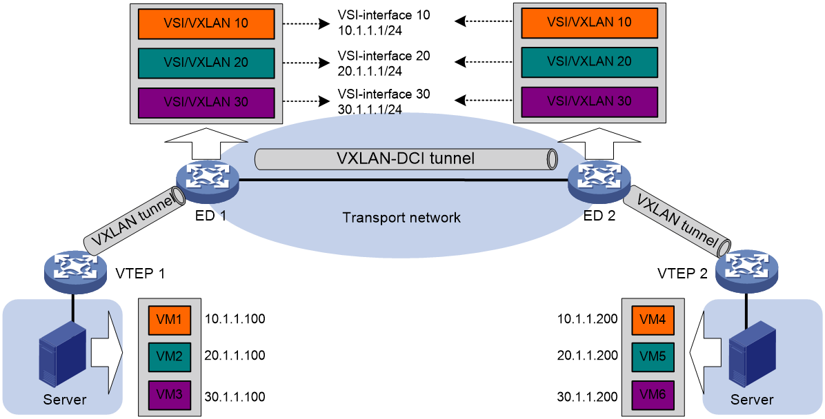
Intra-VXLAN traffic forwarding between sites
As shown in Figure 23, the network uses the following process to forward traffic in a VXLAN between sites (for example, from VM 1 to VM 4 in VXLAN 10):
1. VM 1 sends an ARP request to obtain the MAC address of VM 4.
2. VTEP 1 learns the MAC address of VM 1 and floods the ARP request in VXLAN 10.
3. ED 1 performs the following operations:
a. Removes the VXLAN encapsulation of the ARP request.
b. Creates an ARP entry for VM 1 and replies with the MAC address of VSI-interface 10 (the gateway interface for VXLAN 10). The ARP reply is sent to VTEP 1.
4. VTEP 1 removes the VXLAN encapsulation of the ARP reply, learns the MAC address of ED 1, and forwards the ARP reply to VM 1.
5. VM 1 creates an ARP entry for VM 4. The MAC address in the entry is the MAC address of VSI-interface 10 on ED 1.
6. ED 1 replaces the sender MAC address of the request with the MAC address of VSI-interface 10 on ED 1, and then floods the request to the remote EDs in VXLAN 10.
7. ED 2 performs the following operations:
a. Removes the VXLAN encapsulation of the ARP request.
b. Creates an ARP entry for VM 1. The entry contains VM 1's IP address (10.1.1.100), the MAC address of VSI-interface 10 on ED 1, and the incoming VXLAN-DCI tunnel interface.
c. Replaces the sender MAC address of the request with the MAC address of VSI-interface 10 on ED 2, and then floods the request on all VXLAN tunnels of VXLAN 10.
8. VTEP 2 removes the VXLAN encapsulation of the ARP request, learns the MAC address of ED 2, and floods the ARP request to the local site.
9. VM 4 creates an ARP entry for VM 1, and then sends a reply to VTEP 2. The MAC address in the ARP entry is the MAC address of VSI-interface 10 on ED 2.
10. VTEP 2 looks up the MAC address table and forwards the ARP reply to ED 2.
11. ED 2 performs the following operations:
a. Removes the VXLAN encapsulation of the ARP reply.
b. Creates an ARP entry for VM 4
c. Replaces the sender MAC address of the ARP reply with the MAC address of VSI-interface 10 on ED 2, and sends the reply to ED 1.
12. ED 1 performs the following operations:
a. Removes the VXLAN encapsulation of the ARP reply.
b. Creates an ARP entry for VM 4. The entry contains VM 4's IP address (10.1.1.200), the MAC address of VSI-interface 10 on ED 2, and the incoming VXLAN-DCI tunnel interface.
13. For subsequent traffic between VM 1 and VM 4, the VTEPs and EDs use their respective MAC address tables and ARP tables to make the forwarding decision.
Inter-VXLAN traffic forwarding between sites
As shown in Figure 23, the network uses the following process to forward traffic between VXLANs (for example, from VM 1 in VXLAN 10 to VM 5 in VXLAN 20):
1. VM 1 sends an ARP request to obtain the MAC address of the gateway at 10.1.1.1.
2. VTEP 1 learns the MAC address of VM 1 and floods the ARP request in VXLAN 10.
3. ED 1 performs the following operations:
a. Removes the VXLAN encapsulation of the ARP request.
b. Creates an ARP entry for VM 1 and replies with the MAC address of VSI-interface 10 (the gateway interface for VXLAN 10). The ARP reply is sent to VTEP 1.
4. VTEP 1 removes the VXLAN encapsulation of the ARP reply, learns the MAC address of ED 1, and forwards the ARP reply to VM 1.
5. VM 1 creates an ARP entry for the gateway and sends the packet destined for VM 5 to VTEP 1.
6. VTEP 1 looks up the MAC address table and forwards the packet to ED 1.
7. ED 1 performs the following operations:
a. Removes the VXLAN encapsulation of the packet and looks up the routing table based on the destination IP address.
b. Sends an ARP request to the local VTEP and remote ED of VXLAN 20 to obtain the MAC address of VM 5. In the ARP request, the sender IP address is 20.1.1.1, and the sender MAC address is the MAC address of VSI-interface 20 on ED 1.
8. ED 2 performs the following operations:
a. Removes the VXLAN encapsulation of the ARP request.
b. Replaces the sender MAC address of the request with the MAC address of VSI-interface 20 on ED 2, and then floods the request on all VXLAN tunnels of VXLAN 20.
9. VTEP 2 removes the VXLAN encapsulation of the ARP request, learns the MAC address of ED 2, and floods the ARP request to the local site.
10. VM 5 creates an ARP entry for ED 2 and sends a reply to VTEP 2. The MAC address in the ARP entry is the MAC address of VSI-interface 20 on ED 2.
11. VTEP 2 looks up the MAC address table and forwards the ARP reply to ED 2.
12. ED 2 performs the following operations:
a. Removes the VXLAN encapsulation of the ARP reply.
b. Creates an ARP entry for VM 5.
c. Sends a gratuitous ARP packet to ED 1. In the packet, the sender and target IP address is 20.1.1.200, and the sender MAC address is the MAC address of VSI-interface 20 on ED 2.
13. ED 1 performs the following operations:
a. Removes the VXLAN encapsulation of the packet.
b. Creates an ARP entry for VM 5. The entry contains VM 5's IP address (20.1.1.200), the MAC address of VSI-interface 20 on ED 2, and the incoming VXLAN-DCI tunnel interface.
14. For subsequent traffic between VM 1 and VM 5, the VTEPs and EDs use their respective MAC address tables and ARP tables to make the forwarding decision.
Feature and hardware compatibility
VXLAN-DCI is not supported on switches labeled with the following product codes:
· LS-6800-2C.
· LS-6800-4C.
· LS-6800-32Q.
· LS-6800-54QF.
· LS-6800-54QT.
VXLAN-DCI configuration task list
To configure a VXLAN-DCI network, perform the following tasks:
· Configure routing protocols on the transport network for EDs to reach one another.
· Configure routing protocols on EDs and VTEPs for them to reach one another.
· Configure VXLANs on EDs and VTEPs, and set up VXLAN tunnels between EDs and VTEPs.
· Configure VXLAN-DCI on EDs, and set up VXLAN-DCI tunnels between EDs.
Table 2 lists the VXLAN-DCI configuration tasks available on an ED. For more information about basic VXLAN configuration and VXLAN IP gateway configuration, see "Configuring basic VXLAN features" and "Configuring VXLAN IP gateways."
Table 2 VXLAN-DCI configuration task list
|
Tasks at a glance |
Remarks |
|
(Required.) Setting the VXLAN hardware resource mode to border |
For more information, see "Setting the VXLAN hardware resource mode." |
|
(Required.) Creating a VXLAN on a VSI |
N/A |
|
(Required.) Configuring a VXLAN-DCI tunnel |
N/A |
|
(Required.) Assigning a VXLAN-DCI tunnel to a VXLAN |
N/A |
|
(Required.) Configuring a VSI interface |
N/A |
|
(Required.) Specifying a gateway interface for a VSI |
N/A |
|
(Optional.) Enabling packet statistics for a VSI interface |
N/A |
|
(Optional.) Setting the destination UDP port number of VXLAN packets |
N/A |
|
(Optional.) Configuring VXLAN packet check |
N/A |
|
(Optional.) Enabling packet statistics for a VSI |
N/A |
|
(Optional.) Enabling packet statistics for manually created VXLAN-DCI tunnels |
N/A |
Configuring a VXLAN-DCI tunnel
You must specify the tunnel source and destination IP addresses when you manually set up a VXLAN-DCI tunnel between EDs. As a best practice, do not configure the same tunnel source and destination addresses for different VXLAN-DCI tunnels on an ED.
This task provides basic VXLAN-DCI tunnel configuration. For more information about tunnel configuration and commands, see Layer 3—IP Services Configuration Guide and Layer 3—IP Services Command Reference.
To configure a VXLAN-DCI tunnel:
|
Step |
Command |
Remarks |
|
1. Enter system view. |
system-view |
N/A |
|
2. Create a VXLAN-DCI tunnel interface and enter tunnel interface view. |
interface tunnel tunnel-number mode vxlan-dci |
By default, no tunnel interfaces exist. The endpoints of a tunnel must use the same tunnel mode. |
|
3. Specify a source IP address or source interface for the tunnel. |
source { ipv4-address | interface-type interface-number } |
By default, no source IP address or source interface is specified for a tunnel. This step specifies the source IP address in the outer IP header of tunneled VXLAN packets. If an interface is specified, its primary IP address is used. |
|
4. Specify a destination IP address for the tunnel. |
destination ipv4-address |
By default, no destination IP address is specified for a tunnel. Specify the remote ED's IP address. This IP address will be the destination IP address in the outer IP header of tunneled VXLAN packets. |
Assigning a VXLAN-DCI tunnel to a VXLAN
To provide connectivity for a VXLAN between two EDs, you must assign the VXLAN-DCI tunnel between the EDs to the VXLAN.
You can assign multiple VXLAN-DCI tunnels to a VXLAN, and configure a VXLAN-DCI tunnel to trunk multiple VXLANs. EDs use the VXLAN ID in VXLAN packets to identify the VXLAN. For a unicast-mode VXLAN, the system floods unknown unicast, multicast, and broadcast traffic to each VXLAN-DCI tunnel associated with the VXLAN.
To assign a VXLAN-DCI tunnel to a VXLAN:
|
Step |
Command |
Remarks |
|
1. Enter system view. |
system-view |
N/A |
|
2. Enter VSI view. |
vsi vsi-name |
N/A |
|
3. Enter VXLAN view. |
vxlan vxlan-id |
N/A |
|
4. Assign a VXLAN-DCI tunnel to the VXLAN. |
tunnel tunnel-number |
By default, a VXLAN does not contain any VXLAN-DCI tunnels. For full connectivity in the VXLAN, make sure the VXLAN contains the VXLAN-DCI tunnel between each pair of EDs in the VXLAN. |
Configuring a VSI interface
|
Step |
Command |
Remarks |
|
1. Enter system view. |
system-view |
N/A |
|
2. Create a VSI interface and enter VSI interface view. |
interface vsi-interface vsi-interface-id |
By default, no VSI interfaces exist. |
|
3. Assign an IPv4 or IPv6 address to the VSI interface. |
· Assign an IPv4 address: · Assign an IPv6 address: |
By default, no IPv4 or IPv6 address is assigned to a VSI interface. This interface will be used as a gateway for VXLANs. |
|
4. Specify the VSI interface as a distributed gateway. |
distributed-gateway local |
By default, a VSI interface is not a distributed gateway. |
|
5. Enable local proxy ARP or local ND proxy. |
· Enable local proxy ARP on an IPv4 gateway: · Enable local ND proxy on an IPv6 gateway: |
By default, local proxy ARP and local ND proxy are disabled. For more information about the commands, see Layer 3—IP Services Command Reference. |
|
6. Assign a MAC address to the VSI interface. |
mac-address mac-address |
By default, all VSI interfaces on a device use a fixed MAC address. The MAC addresses of VSI interfaces on different devices are different. |
|
7. (Optional.) Configure the description of the VSI interface. |
description text |
The default description of a VSI interface is interface-name plus Interface (for example, Vsi-interface100 Interface). |
|
8. (Optional.) Set the MTU for the VSI interface. |
mtu mtu-value |
The default MTU of a VSI interface is 1444 bytes. Make sure the MTU is a minimum of 36 bytes less than the MTU of the physical outgoing interface. |
|
9. (Optional.) Set the expected bandwidth for the VSI interface. |
bandwidth bandwidth-value |
The default expected bandwidth (in kbps) equals the interface baud rate divided by 1000. |
|
10. (Optional.) Restore the default settings on the interface. |
default |
N/A |
|
11. (Optional.) Set an ARP packet sending rate limit for the VSI interface. |
arp send-rate pps |
By default, the ARP packet sending rate is not limited for a VSI interface. |
|
12. Bring up the interface. |
undo shutdown |
By default, a VSI interface is not manually shut down. |
Specifying a gateway interface for a VSI
|
Step |
Command |
Remarks |
|
1. Enter system view. |
system-view |
N/A |
|
2. Enter VSI view. |
vsi vsi-name |
N/A |
|
3. Specify a gateway interface for the VSI. |
gateway vsi-interface vsi-interface-id |
By default, no gateway interface is specified for a VSI. |
Enabling packet statistics for manually created VXLAN-DCI tunnels
|
|
IMPORTANT: This feature is available in Release 2612 and later. |
Perform this task to enable packet statistics for manually created VXLAN-DCI tunnels on a per-tunnel interface basis. To display the packet statistics for VXLAN-DCI tunnels, use the display interface tunnel command in any view. To clear the packet statistics for VXLAN-DCI tunnels, use the reset counters interface tunnel command in user view.
To enable packet statistics for manually created VXLAN-DCI tunnels:
|
Step |
Command |
Remarks |
|
1. Enter system view. |
system-view |
N/A |
|
2. Enter VXLAN-DCI tunnel interface view. |
interface tunnel tunnel-number mode vxlan-dci |
N/A |
|
3. Enable packet statistics for the tunnel. |
statistics enable |
By default, the packet statistics feature is disabled for manually created VXLAN-DCI tunnels. |
Displaying and maintaining VXLAN-DCI
Execute display commands in any view and reset commands in user view.
|
Task |
Command |
|
Display information about VSIs. |
display l2vpn vsi [ name vsi-name ] [ verbose ] |
|
Display information about tunnel interfaces. |
display interface [ tunnel [ number ] ] [ brief [ description | down ] ] |
|
Display VXLAN-DCI tunnel information for VXLANs. |
display vxlan tunnel [ vxlan-id vxlan-id ] |
|
Clear packet statistics on VSIs. |
reset l2vpn statistics vsi [ name vsi-name ] |
|
|
NOTE: For more information about the display interface tunnel command, see tunneling commands in Layer 3—IP Services Command Reference. |
VXLAN-DCI configuration example
Network requirements
As shown in Figure 24:
· Configure VXLAN 10 and VXLAN 20 as unicast-mode VXLANs on Switch A, Switch B, Switch D, and Switch E to provide connectivity for the VMs across the data center sites.
· Configure Switch A and Switch E as VTEPs, and Switch B and Switch D as EDs.
· Manually establish VXLAN tunnels and VXLAN-DCI tunnels, and assign the tunnels to the VXLANs.
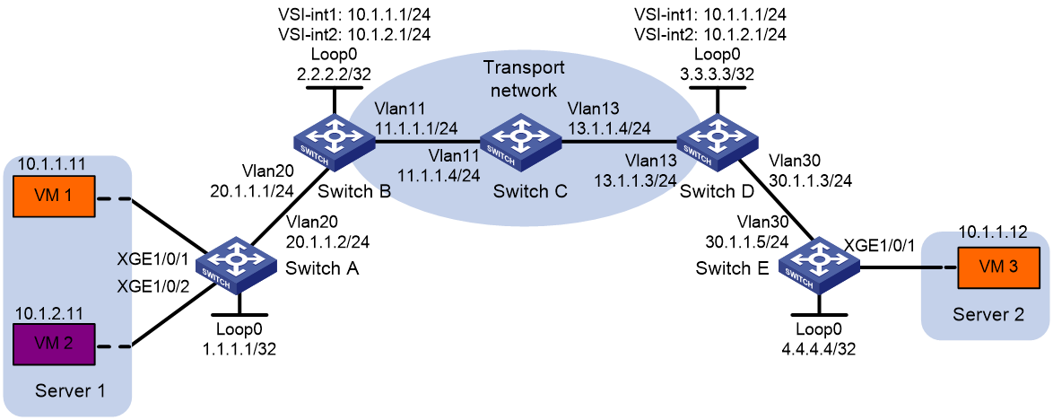
Configuration procedure
1. Configure IP addresses and unicast routing settings:
# Assign IP addresses to interfaces, as shown in Figure 24. (Details not shown.)
# Configure OSPF on Switches A through E. (Details not shown.)
# Configure OSPF to advertise routes to networks 10.1.1.0/24 and 10.1.2.0/24 on Switch B and Switch D. (Details not shown.)
2. Configure Switch A:
# Enable L2VPN.
<SwitchA> system-view
[SwitchA] l2vpn enable
# Create VSI vpna and VXLAN 10.
[SwitchA] vsi vpna
[SwitchA-vsi-vpna] vxlan 10
[SwitchA-vsi-vpna-vxlan-10] quit
[SwitchA-vsi-vpna] quit
# Create VSI vpnb and VXLAN 20.
[SwitchA] vsi vpnb
[SwitchA-vsi-vpnb] vxlan 20
[SwitchA-vsi-vpnb-vxlan-20] quit
[SwitchA-vsi-vpnb] quit
# Assign an IP address to Loopback 0. The IP address will be used as the source IP address of the VXLAN tunnel to Switch B.
[SwitchA] interface loopback 0
[SwitchA-Loopback0] ip address 1.1.1.1 255.255.255.255
[SwitchA-Loopback0] quit
# Create a VXLAN tunnel to Switch B. The tunnel interface name is Tunnel 1.
[SwitchA] interface tunnel 1 mode vxlan
[SwitchA-Tunnel1] source 1.1.1.1
[SwitchA-Tunnel1] destination 2.2.2.2
[SwitchA-Tunnel1] quit
# Assign Tunnel 1 to VXLAN 10.
[SwitchA] vsi vpna
[SwitchA-vsi-vpna] vxlan 10
[SwitchA-vsi-vpna-vxlan-10] tunnel 1
[SwitchA-vsi-vpna-vxlan-10] quit
[SwitchA-vsi-vpna] quit
# Assign Tunnel 1 to VXLAN 20.
[SwitchA] vsi vpnb
[SwitchA-vsi-vpnb] vxlan 20
[SwitchA-vsi-vpnb-vxlan-20] tunnel 1
[SwitchA-vsi-vpnb-vxlan-20] quit
[SwitchA-vsi-vpnb] quit
# On Ten-GigabitEthernet 1/0/1, create Ethernet service instance 1000 to match VLAN 100.
[SwitchA] interface ten-gigabitethernet 1/0/1
[SwitchA-Ten-GigabitEthernet1/0/1] service-instance 1000
[SwitchA-Ten-GigabitEthernet1/0/1-srv1000] encapsulation s-vid 100
# Map Ethernet service instance 1000 on Ten-GigabitEthernet 1/0/1 to VSI vpna.
[SwitchA-Ten-GigabitEthernet1/0/1-srv1000] xconnect vsi vpna
[SwitchA-Ten-GigabitEthernet1/0/1-srv1000] quit
[SwitchA-Ten-GigabitEthernet1/0/1] quit
# On Ten-GigabitEthernet 1/0/2, create Ethernet service instance 1000 to match VLAN 200.
[SwitchA] interface ten-gigabitethernet 1/0/2
[SwitchA-Ten-GigabitEthernet1/0/2] service-instance 1000
[SwitchA-Ten-GigabitEthernet1/0/2-srv1000] encapsulation s-vid 200
# Map Ethernet service instance 1000 on Ten-GigabitEthernet 1/0/2 to VSI vpnb.
[SwitchA-Ten-GigabitEthernet1/0/2-srv1000] xconnect vsi vpnb
[SwitchA-Ten-GigabitEthernet1/0/2-srv1000] quit
[SwitchA-Ten-GigabitEthernet1/0/2] quit
3. Configure Switch B:
# Enable L2VPN.
<SwitchB> system-view
[SwitchB] l2vpn enable
# Set the VXLAN hardware resource mode.
[SwitchB] hardware-resource vxlan border8k
# Create VSI vpna and VXLAN 10.
[SwitchB] vsi vpna
[SwitchB-vsi-vpna] vxlan 10
[SwitchB-vsi-vpna-vxlan-10] quit
[SwitchB-vsi-vpna] quit
# Create VSI vpnb and VXLAN 20.
[SwitchB] vsi vpnb
[SwitchB-vsi-vpnb] vxlan 20
[SwitchB-vsi-vpnb-vxlan-20] quit
[SwitchB-vsi-vpnb] quit
# Assign an IP address to Loopback 0. The IP address will be used as the source IP address of the VXLAN tunnel to Switch A and the VXLAN-DCI tunnel to Switch D.
[SwitchB] interface loopback 0
[SwitchB-Loopback0] ip address 2.2.2.2 255.255.255.255
[SwitchB-Loopback0] quit
# Create a VXLAN tunnel to Switch A. The tunnel interface name is Tunnel 1.
[SwitchB] interface tunnel 1 mode vxlan
[SwitchB-Tunnel1] source 2.2.2.2
[SwitchB-Tunnel1] destination 1.1.1.1
[SwitchB-Tunnel1] quit
# Create a VXLAN-DCI tunnel to Switch D. The tunnel interface name is Tunnel 2.
[SwitchB] interface tunnel 2 mode vxlan-dci
[SwitchB-Tunnel2] source 2.2.2.2
[SwitchB-Tunnel2] destination 3.3.3.3
[SwitchB-Tunnel2] quit
# Assign Tunnel 1 and Tunnel 2 to VXLAN 10.
[SwitchB] vsi vpna
[SwitchB-vsi-vpna] vxlan 10
[SwitchB-vsi-vpna-vxlan-10] tunnel 1
[SwitchB-vsi-vpna-vxlan-10] tunnel 2
[SwitchB-vsi-vpna-vxlan-10] quit
[SwitchB-vsi-vpna] quit
# Assign Tunnel 1 and Tunnel 2 to VXLAN 20.
[SwitchB] vsi vpnb
[SwitchB-vsi-vpnb] vxlan 20
[SwitchB-vsi-vpnb-vxlan-20] tunnel 1
[SwitchB-vsi-vpnb-vxlan-20] tunnel 2
[SwitchB-vsi-vpnb-vxlan-20] quit
[SwitchB-vsi-vpnb] quit
# Create VSI-interface 1 and assign the interface an IP address. The IP address will be used as the gateway address for VXLAN 10.
[SwitchB] interface vsi-interface 1
[SwitchB-Vsi-interface1] ip address 10.1.1.1 255.255.255.0
# Specify VSI-interface 1 as a distributed gateway and enable local proxy ARP on the interface.
[SwitchB-Vsi-interface1] distributed-gateway local
[SwitchB-Vsi-interface1] local-proxy-arp enable
[SwitchB-Vsi-interface1] quit
# Create VSI-interface 2 and assign the interface an IP address. The IP address will be used as the gateway address for VXLAN 20.
[SwitchB] interface vsi-interface 2
[SwitchB-Vsi-interface2] ip address 10.1.2.1 255.255.255.0
# Specify VSI-interface 2 as a distributed gateway and enable local proxy ARP on the interface.
[SwitchB-Vsi-interface2] distributed-gateway local
[SwitchB-Vsi-interface2] local-proxy-arp enable
[SwitchB-Vsi-interface2] quit
# Enable dynamic ARP entry synchronization for distributed VXLAN IP gateways.
[SwitchB] arp distributed-gateway dynamic-entry synchronize
# Specify VSI-interface 1 as the gateway interface for VSI vpna.
[SwitchB] vsi vpna
[SwitchB-vsi-vpna] gateway vsi-interface 1
[SwitchB-vsi-vpna] quit
# Specify VSI-interface 2 as the gateway interface for VSI vpnb.
[SwitchB] vsi vpnb
[SwitchB-vsi-vpnb] gateway vsi-interface 2
[SwitchB-vsi-vpnb] quit
4. Configure Switch D:
# Enable L2VPN.
<SwitchD> system-view
[SwitchD] l2vpn enable
# Set the VXLAN hardware resource mode.
[SwitchD] hardware-resource vxlan border8k
# Create VSI vpna and VXLAN 10.
[SwitchD] vsi vpna
[SwitchD-vsi-vpna] vxlan 10
[SwitchD-vsi-vpna-vxlan-10] quit
[SwitchD-vsi-vpna] quit
# Create VSI vpnb and VXLAN 20.
[SwitchD] vsi vpnb
[SwitchD-vsi-vpnb] vxlan 20
[SwitchD-vsi-vpnb-vxlan-20] quit
[SwitchD-vsi-vpnb] quit
# Assign an IP address to Loopback 0. The IP address will be used as the source IP address of the VXLAN-DCI tunnel to Switch B and the VXLAN tunnel to Switch E.
[SwitchD] interface loopback 0
[SwitchD-Loopback0] ip address 3.3.3.3 255.255.255.255
[SwitchD-Loopback0] quit
# Create a VXLAN tunnel to Switch E. The tunnel interface name is Tunnel 1.
[SwitchD] interface tunnel 1 mode vxlan
[SwitchD-Tunnel1] source 3.3.3.3
[SwitchD-Tunnel1] destination 4.4.4.4
[SwitchD-Tunnel1] quit
# Create a VXLAN-DCI tunnel to Switch B. The tunnel interface name is Tunnel 2.
[SwitchD] interface tunnel 2 mode vxlan-dci
[SwitchD-Tunnel2] source 3.3.3.3
[SwitchD-Tunnel2] destination 2.2.2.2
[SwitchD-Tunnel2] quit
#Assign Tunnel 1 and Tunnel 2 to VXLAN 10.
[SwitchD] vsi vpna
[SwitchD-vsi-vpna] vxlan 10
[SwitchD-vsi-vpna-vxlan-10] tunnel 1
[SwitchD-vsi-vpna-vxlan-10] tunnel 2
[SwitchD-vsi-vpna-vxlan-10] quit
[SwitchD-vsi-vpna] quit
# Assign Tunnel 2 to VXLAN 20.
[SwitchD] vsi vpnb
[SwitchD-vsi-vpnb] vxlan 20
[SwitchD-vsi-vpnb-vxlan-20] tunnel 2
[SwitchD-vsi-vpnb-vxlan-20] quit
[SwitchD-vsi-vpnb] quit
# Create VSI-interface 1 and assign the interface an IP address. The IP address will be used as the gateway address for VXLAN 10.
[SwitchD] interface vsi-interface 1
[SwitchD-Vsi-interface1] ip address 10.1.1.1 255.255.255.0
# Specify VSI-interface 1 as a distributed gateway and enable local proxy ARP on the interface.
[SwitchD-Vsi-interface1] distributed-gateway local
[SwitchD-Vsi-interface1] local-proxy-arp enable
[SwitchD-Vsi-interface1] quit
# Create VSI-interface 2 and assign the interface an IP address. The IP address will be used as the gateway address for VXLAN 20.
[SwitchD] interface vsi-interface 2
[SwitchD-Vsi-interface2] ip address 10.1.2.1 255.255.255.0
# Specify VSI-interface 2 as a distributed gateway and enable local proxy ARP on the interface.
[SwitchD-Vsi-interface2] distributed-gateway local
[SwitchD-Vsi-interface2] local-proxy-arp enable
[SwitchD-Vsi-interface2] quit
# Enable dynamic ARP entry synchronization for distributed VXLAN IP gateways.
[SwitchD] arp distributed-gateway dynamic-entry synchronize
# Specify VSI-interface 1 as the gateway interface for VSI vpna.
[SwitchD] vsi vpna
[SwitchD-vsi-vpna] gateway vsi-interface 1
[SwitchD-vsi-vpna] quit
# Specify VSI-interface 2 as the gateway interface for VSI vpnb.
[SwitchD] vsi vpnb
[SwitchD-vsi-vpnb] gateway vsi-interface 2
[SwitchD-vsi-vpnb] quit
5. Configure Switch E:
# Enable L2VPN.
<SwitchE> system-view
[SwitchE] l2vpn enable
# Create VSI vpna and VXLAN 10.
[SwitchE] vsi vpna
[SwitchE-vsi-vpna] vxlan 10
[SwitchE-vsi-vpna-vxlan-10] quit
[SwitchE-vsi-vpna] quit
# Assign an IP address to Loopback 0. The IP address will be used as the source IP address of the VXLAN tunnel to Switch D.
[SwitchE] interface loopback 0
[SwitchE-Loopback0] ip address 4.4.4.4 255.255.255.255
[SwitchE-Loopback0] quit
# Create a VXLAN tunnel to Switch D. The tunnel interface name is Tunnel 1.
[SwitchE] interface tunnel 1 mode vxlan
[SwitchE-Tunnel1] source 4.4.4.4
[SwitchE-Tunnel1] destination 3.3.3.3
[SwitchE-Tunnel1] quit
# Assign Tunnel 1 to VXLAN 10.
[SwitchE] vsi vpna
[SwitchE-vsi-vpna] vxlan 10
[SwitchE-vsi-vpna-vxlan-10] tunnel 1
[SwitchE-vsi-vpna-vxlan-10] quit
[SwitchE-vsi-vpna] quit
# On Ten-GigabitEthernet 1/0/1, create Ethernet service instance 1000 to match VLAN 100.
[SwitchA] interface ten-gigabitethernet 1/0/1
[SwitchA-Ten-GigabitEthernet1/0/1] service-instance 1000
[SwitchA-Ten-GigabitEthernet1/0/1-srv1000] encapsulation s-vid 100
# Map Ethernet service instance 1000 to VSI vpna.
[SwitchA-Ten-GigabitEthernet1/0/1-srv1000] xconnect vsi vpna
[SwitchA-Ten-GigabitEthernet1/0/1-srv1000] quit
[SwitchA-Ten-GigabitEthernet1/0/1] quit
Verifying the configuration
1. Verify the VXLAN-DCI settings on the EDs. This example uses Switch B.
# Verify that the VXLAN and VXLAN-DCI tunnel interfaces are up on Switch B.
[SwitchB] display interface tunnel
Tunnel1
Current state: UP
Line protocol state: UP
Description: Tunnel1 Interface
Bandwidth: 64 kbps
Maximum transmission unit: 1464
Internet protocol processing: Disabled
Last clearing of counters: Never
Tunnel source 2.2.2.2, destination 1.1.1.1
Tunnel protocol/transport UDP_VXLAN/IP
Last 300 seconds input rate: 0 bytes/sec, 0 bits/sec, 0 packets/sec
Last 300 seconds output rate: 0 bytes/sec, 0 bits/sec, 0 packets/sec
Input: 0 packets, 0 bytes, 0 drops
Output: 0 packets, 0 bytes, 0 drops
Tunnel2
Current state: UP
Line protocol state: UP
Description: Tunnel2 Interface
Bandwidth: 64 kbps
Maximum transmission unit: 1464
Internet protocol processing: Disabled
Last clearing of counters: Never
Tunnel source 2.2.2.2, destination 3.3.3.3
Tunnel protocol/transport UDP_VXLAN_DCI/IP
Last 300 seconds input rate: 0 bytes/sec, 0 bits/sec, 0 packets/sec
Last 300 seconds output rate: 0 bytes/sec, 0 bits/sec, 0 packets/sec
Input: 0 packets, 0 bytes, 0 drops
Output: 0 packets, 0 bytes, 0 drops
# Verify that VSI-interface 1 and VSI-interface 2 are up.
[SwitchB] display interface vsi-interface
Vsi-interface1
Current state: UP
Line protocol state: UP
Description: Vsi-interface1 Interface
Bandwidth: 1000000 kbps
Maximum transmission unit: 1444
Internet address: 10.1.1.1/24 (primary)
IP packet frame type:PKTFMT_ETHNT_2, hardware address: 0011-2200-0102
IPv6 packet frame type:PKTFMT_ETHNT_2, hardware address: 0011-2200-0102
Physical: Unknown, baudrate: 1000000 kbps
Last clearing of counters: Never
Input (total): 0 packets, 0 bytes
Output (total): 0 packets, 0 bytes
Vsi-interface2
Current state: UP
Line protocol state: UP
Description: Vsi-interface2 Interface
Bandwidth: 1000000 kbps
Maximum transmission unit: 1444
Internet address: 10.1.2.1/24 (primary)
IP packet frame type:PKTFMT_ETHNT_2, hardware address: 0011-3300-0102
IPv6 packet frame type:PKTFMT_ETHNT_2, hardware address: 0011-3300-0102
Physical: Unknown, baudrate: 1000000 kbps
Last clearing of counters: Never
Input (total): 0 packets, 0 bytes
Output (total): 0 packets, 0 bytes
# Verify that the VXLAN and VXLAN-DCI tunnels have been assigned to VXLAN 10 and VXLAN 20, and the VSI interfaces are the gateway interfaces for their respective VSIs.
[SwitchB] display l2vpn vsi verbose
VSI Name: vpna
VSI Index : 0
VSI State : Up
MTU : 1500
Bandwidth : Unlimited
Broadcast Restrain : Unlimited
Multicast Restrain : Unlimited
Unknown Unicast Restrain: Unlimited
MAC Learning : Enabled
MAC Table Limit : -
MAC Learning rate : -
Drop Unknown : -
Flooding : Enabled
Statistics : Disabled
Gateway interface : VSI-interface 1
VXLAN ID : 10
Tunnels:
Tunnel Name Link ID State Type Flood proxy
Tunnel1 0x5000001 Up Manual Disabled
Tunnel2 0x5000002 Up Manual Disabled
VSI Name: vpnb
VSI Index : 0
VSI State : Up
MTU : 1500
Bandwidth : Unlimited
Broadcast Restrain : Unlimited
Multicast Restrain : Unlimited
Unknown Unicast Restrain: Unlimited
MAC Learning : Enabled
MAC Table Limit : -
MAC Learning rate : -
Drop Unknown : -
Flooding : Enabled
Statistics : Disabled
Gateway interface : VSI-interface 2
VXLAN ID : 20
Tunnels:
Tunnel Name Link ID State Type Flood proxy
Tunnel1 0x5000001 Up Manual Disabled
Tunnel2 0x5000002 Up Manual Disabled
# Verify that Switch B has created ARP entries for the VMs.
[SwitchB] display arp
Type: S-Static D-Dynamic O-Openflow R-Rule M-Multiport I-Invalid
IP address MAC address VLAN/VSI Interface/Link ID Aging Type
11.1.1.4 000c-29c1-5e46 N/A Vlan11 19 D
10.1.1.11 0cda-41b5-cf09 N/A Vsi1 20 D
10.1.1.12 0011-4400-0102 N/A Vsi1 20 D
10.1.2.11 0cda-41b5-cf89 N/A Vsi2 20 D
2. Verify that VM 1, VM 2, and VM 3 can ping each other. (Details not shown.)
Configuring the VTEP as an OVSDB VTEP
Overview
An H3C network virtualization controller can use the Open vSwitch Database (OVSDB) management protocol to deploy and manage VXLANs on VTEPs. To work with a controller, you must configure the VTEP as an OVSDB VTEP.
As shown in Figure 25, an OVSDB VTEP stores all of its VXLAN settings in the form of entries in an OVSDB database. The OVSDB database, OVSDB VTEP service, and the controller interact through the OVSDB server. The controller communicates with the OVSDB server through the OVSDB protocol to manage the OVSDB database. The OVSDB VTEP service reads and writes data in the OVSDB database through the OVSDB server.
The OVSDB VTEP service performs the following operations to manage the VXLAN settings on the VTEP:
· Converts data in the OVSDB database into VXLAN configuration and deploys the configuration to the VTEP. For example, create or remove a VXLAN or VXLAN tunnel.
· Adds site-facing interface information and the global source address of VXLAN tunnels to the OVSDB database. The information is reported to the controller by the OVSDB server.
You can configure a VTEP both at the CLI and through a controller. As a best practice, do not manually remove the VXLAN configuration issued by the controller.
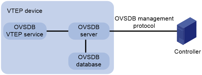
Protocols and standards
RFC 7047, The Open vSwitch Database Management Protocol
OVSDB VTEP configuration task list
|
Tasks at a glance |
|
(Required.) Setting up an OVSDB connection to a controller: · Configuring active SSL connection settings · Configuring passive SSL connection settings |
|
(Required.) Enabling the OVSDB server |
|
(Required.) Enabling the OVSDB VTEP service |
|
(Required.) Specifying a global source address for VXLAN tunnels |
|
(Required.) Specifying a VTEP access port |
|
(Optional.) Enabling flood proxy on multicast VXLAN tunnels |
Configuration prerequisites
Before you configure the VTEP as an OVSDB VTEP, enable L2VPN by using the l2vpn enable command.
Before you set up SSL connections to controllers, you must configure SSL as described in Security Configuration Guide.
Setting up an OVSDB connection to a controller
The OVSDB server supports the following types of OVSDB connections:
· Active SSL connection—The OVSDB server initiates an SSL connection to the controller.
· Passive SSL connection—The OVSDB server accepts the SSL connection from the controller.
· Active TCP connection—The OVSDB server initiates a TCP connection to the controller.
· Passive TCP connection—The OVSDB server accepts the TCP connection from the controller.
Configuration restrictions and guidelines
When you set up OVSDB connections, follow these restrictions and guidelines:
· You can set up multiple OVSDB connections. For the device to establish the connections, you must enable the OVSDB server. You must disable and then re-enable the OVSDB server if it has been enabled before OVSDB connections are configured, or OVSDB connection changes or SSL version changes are made.
· You must specify the same PKI domain and CA certificate file for all active and passive SSL connections.
· Make sure you have configured the PKI domain before specify it for SSL. For more information about configuring a PKI domain, see Security Configuration Guide.
Configuring active SSL connection settings
|
Step |
Command |
Remarks |
|
1. Enter system view. |
system-view |
N/A |
|
2. Specify a PKI domain for SSL. |
ovsdb server pki domain domain-name |
By default, no PKI domain is specified for SSL. |
|
3. (Optional.) Specify a CA certificate file for SSL. |
ovsdb server bootstrap ca-certificate ca-filename |
By default, SSL uses the CA certificate file in the PKI domain. If the specified CA certificate file does not exist, the device obtains a self-signed certificate from the controller. The obtained file uses the name specified for the ca-filename argument. |
|
4. Set up an active SSL connection. |
ovsdb server ssl ip ip-address port port-number |
By default, the device does not have active OVSDB SSL connections. You can set up a maximum of eight OVSDB SSL connections. |
Configuring passive SSL connection settings
|
Step |
Command |
Remarks |
|
1. Enter system view. |
system-view |
N/A |
|
2. Specify a PKI domain for SSL. |
ovsdb server pki domain domain-name |
By default, no PKI domain is specified for SSL. |
|
3. (Optional.) Specify a CA certificate file for SSL. |
ovsdb server bootstrap ca-certificate ca-filename |
By default, SSL uses the CA certificate file in the PKI domain. If the specified CA certificate file does not exist, the device obtains a self-signed certificate from the controller. The obtained file uses the name specified for the ca-filename argument. |
|
4. Enable the device to listen for SSL connection requests. |
ovsdb server pssl [ port port-number ] |
By default, the device does not listen for SSL connection requests. You can specify only one port to listen for OVSDB SSL connection requests. Port 6640 is used if you do specify a port when you execute the command. |
Configuring active TCP connection settings
|
Step |
Command |
Remarks |
|
1. Enter system view. |
system-view |
N/A |
|
2. Set up an active TCP connection. |
ovsdb server tcp ip ip-address port port-number |
By default, the device does not have active OVSDB TCP connections. You can set up a maximum of eight active OVSDB TCP connections. |
Configuring passive TCP connection settings
|
Step |
Command |
Remarks |
|
1. Enter system view. |
system-view |
N/A |
|
2. Enable the device to listen for TCP connection requests. |
ovsdb server ptcp [ port port-number ] [ acl acl-number ] |
By default, the device does not listen for TCP connection requests. The acl acl-number option is available in Release 2612P06 and later. You can specify only one port to listen for OVSDB TCP connection requests. Port 6640 is used if you do specify a port when you execute the command. |
Enabling the OVSDB server
Make sure you have complete OVSDB connection setup before you enable the OVSDB server. If you change OVSDB connection settings after the OVSDB server is enabled, you must disable and then re-enable the OVSDB server for the change to take effect.
To enable the OVSDB server:
|
Step |
Command |
Remarks |
|
1. Enter system view. |
system-view |
N/A |
|
2. Enable the OVSDB server. |
ovsdb server enable |
By default, the OVSDB server is disabled. |
Enabling the OVSDB VTEP service
|
Step |
Command |
Remarks |
|
1. Enter system view. |
system-view |
N/A |
|
2. Enable the OVSDB VTEP service. |
vtep enable |
By default, the OVSDB VTEP service is disabled. |
Specifying a global source address for VXLAN tunnels
|
|
IMPORTANT: For correct VXLAN deployment and VTEP management, do not manually specify tunnel-specific source addresses for VXLAN tunnels if OVSDB is used. |
The VTEP reports the global VXLAN tunnel source address to the controller for VXLAN tunnel setup.
To specify a global source address for VXLAN tunnels:
|
Step |
Command |
Remarks |
|
1. Enter system view. |
system-view |
N/A |
|
2. Specify a global source address for VXLAN tunnels. |
tunnel global source-address ip-address |
By default, no global source address is specified for VXLAN tunnels. |
Specifying a VTEP access port
For the controller to manage a site-facing interface, you must specify the interface as a VTEP access port.
As a best practice, do not manually configure VXLAN settings on a VTEP access port.
To specify a VTEP access port:
|
Step |
Command |
Remarks |
|
1. Enter system view. |
system-view |
N/A |
|
2. Enter interface view. |
· Enter Layer 2 Ethernet interface view: · Enter Layer 2 aggregate interface view: |
N/A |
|
3. Specify the interface as a VTEP access port. |
vtep access port |
By default, an interface is not a VTEP access port. |
Enabling flood proxy on multicast VXLAN tunnels
|
|
IMPORTANT: Flood proxy is supported on multicast VXLAN tunnels only when the OVSDB controller is a NSX controller from VMware. |
If you use a flood proxy server, you must enable flood proxy globally on multicast tunnels. Then the multicast tunnels are converted into flood proxy tunnels. The VTEP sends broadcast, multicast, and unknown unicast traffic for a VXLAN to the flood proxy server through the tunnels. The flood proxy server then replicates and forwards flood traffic to remote VTEPs.
To enable flood proxy on multicast VXLAN tunnels:
|
Step |
Command |
Remarks |
|
1. Enter system view. |
system-view |
N/A |
|
2. Enable flood proxy on multicast VXLAN tunnels. |
vxlan tunnel flooding-proxy |
By default, flood proxy is disabled on multicast VXLAN tunnels. |
OVSDB VTEP configuration examples
Unicast-mode VXLAN configuration example
Network requirements
As shown in Figure 26, configure the controller cluster to deploy unicast-mode VXLAN 10 to Switch A, Switch B, and Switch C to provide Layer 2 connectivity for the VMs across the network sites.
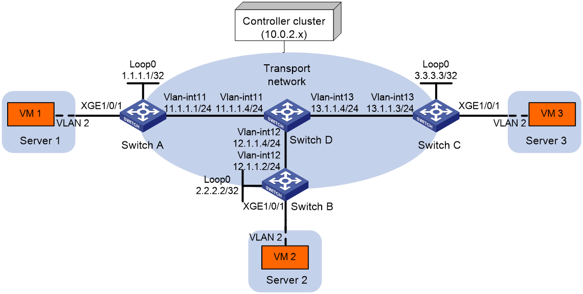
Configuration procedure
1. Configure IP addresses and unicast routing settings:
# Assign IP addresses to interfaces, as shown in Figure 26. (Details not shown.)
# Configure OSPF on all transport network switches (Switches A through D). (Details not shown.)
2. Configure Switch A:
# Enable L2VPN.
<SwitchA> system-view
[SwitchA] l2vpn enable
# Configure active TCP connection settings.
[SwitchA] ovsdb server tcp ip 10.0.2.15 port 6632
# Enable the OVSDB server.
[SwitchA] ovsdb server enable
# Enable the OVSDB VTEP service.
[SwitchA] vtep enable
# Assign an IP address to Loopback 0. Specify the IP address as the global source address for VXLAN tunnels.
[SwitchA] interface loopback 0
[SwitchA-LoopBack0] ip address 1.1.1.1 255.255.255.255
[SwitchA-LoopBack0] quit
[SwitchA] tunnel global source-address 1.1.1.1
# Specify site-facing interface Ten-GigabitEthernet 1/0/1 as a VTEP access port.
[SwitchA] interface ten-gigabitethernet 1/0/1
[SwitchA-Ten-GigabitEthernet1/0/1] vtep access port
[SwitchA-Ten-GigabitEthernet1/0/1] quit
3. Configure Switch B:
# Enable L2VPN.
<SwitchB> system-view
[SwitchB] l2vpn enable
# Configure active TCP connection settings.
[SwitchB] ovsdb server tcp 10.0.2.15 port 6632
# Enable the OVSDB server.
[SwitchB] ovsdb server enable
# Enable the OVSDB VTEP service.
[SwitchB] vtep enable
# Assign an IP address to Loopback 0. Specify the IP address as the global source address for VXLAN tunnels.
[SwitchB] interface loopback 0
[SwitchB-LoopBack0] ip address 2.2.2.2 255.255.255.255
[SwitchB-LoopBack0] quit
[SwitchB] tunnel global source-address 2.2.2.2
# Specify site-facing interface Ten-GigabitEthernet 1/0/1 as a VTEP access port.
[SwitchB] interface ten-gigabitethernet 1/0/1
[SwitchB-Ten-GigabitEthernet1/0/1] vtep access port
[SwitchB-Ten-GigabitEthernet1/0/1] quit
4. Configure Switch C:
# Enable L2VPN.
<SwitchC> system-view
[SwitchC] l2vpn enable
# Configure active TCP connection settings.
[SwitchC] ovsdb server tcp ip 10.0.2.15 port 6632
# Enable the OVSDB server.
[SwitchC] ovsdb server enable
# Enable the OVSDB VTEP service.
[SwitchC] vtep enable
# Assign an IP address to Loopback 0. Specify the IP address as the global source address for VXLAN tunnels.
[SwitchC] interface loopback 0
[SwitchC-LoopBack0] ip address 3.3.3.3 255.255.255.255
[SwitchC-LoopBack0] quit
[SwitchC] tunnel global source-address 3.3.3.3
# Specify site-facing interface Ten-GigabitEthernet 1/0/1 as a VTEP access port.
[SwitchC] interface ten-gigabitethernet 1/0/1
[SwitchC-Ten-GigabitEthernet1/0/1] vtep access port
[SwitchC-Ten-GigabitEthernet1/0/1] quit
5. Configure VXLAN settings on the controller. (Details not shown.)
Verifying the configuration
1. Verify the VXLAN settings on the VTEPs. This example uses Switch A.
# Verify that the VXLAN tunnel interfaces on the VTEP are up.
[SwitchA] display interface tunnel
Tunnel1
Current state: UP
Line protocol state: UP
Description: Tunnel1 Interface
Bandwidth: 64 kbps
Maximum transmission unit: 1464
Internet protocol processing: Disabled
Last clearing of counters: Never
Tunnel source 1.1.1.1, destination 2.2.2.2
Tunnel protocol/transport UDP_VXLAN/IP
Last 300 seconds input rate: 0 bytes/sec, 0 bits/sec, 0 packets/sec
Last 300 seconds output rate: 0 bytes/sec, 0 bits/sec, 0 packets/sec
Input: 0 packets, 0 bytes, 0 drops
Output: 0 packets, 0 bytes, 0 drops
# Verify that the VXLAN tunnels have been assigned to the VXLAN.
[SwitchA] display l2vpn vsi verbose
VSI Name: evpn2014
VSI Index : 0
VSI State : Up
MTU : 1500
Bandwidth : Unlimited
Broadcast Restrain : Unlimited
Multicast Restrain : Unlimited
Unknown Unicast Restrain: Unlimited
MAC Learning : Enabled
MAC Table Limit : -
MAC Learning rate : -
Drop Unknown : -
Flooding : Enabled
Statistics : Disabled
VXLAN ID : 10
Tunnels:
Tunnel Name Link ID State Type Flood proxy
Tunnel1 0x5000001 Up Manual Disabled
Tunnel2 0x5000002 Up Manual Disabled
ACs:
AC Link ID State Type
XGE1/0/1 srv2 0 Up Manual
# Verify that the VTEP has learned the MAC addresses of remote VMs.
<SwitchA> display l2vpn mac-address
MAC Address State VSI Name Link ID/Name Aging
cc3e-5f9c-6cdb Dynamic evpn2014 Tunnel1 Aging
cc3e-5f9c-23dc Dynamic evpn2014 Tunnel2 Aging
--- 2 mac address(es) found ---
2. Verify that VM 1, VM 2, and VM 3 can ping each other. (Details not shown.)
Flood proxy VXLAN configuration example
Network requirements
As shown in Figure 27:
· Configure the controller cluster to deploy VXLAN 10 to Switch A, Switch B, and Switch C to provide Layer 2 connectivity for the VMs across the network sites.
· Enable flood proxy for VXLAN 10.
· Use the MAC address entries issued by the controller to direct traffic forwarding on Switch A, Switch B, and Switch C.
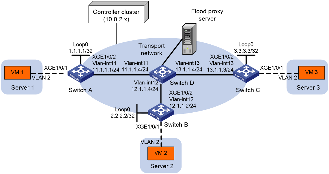
Configuration procedure
1. Configure IP addresses and unicast routing settings:
# Assign IP addresses to interfaces, as shown in Figure 27. (Details not shown.)
# Configure OSPF on all transport network switches (Switches A through D). (Details not shown.)
2. Configure Switch A:
# Enable L2VPN.
<SwitchA> system-view
[SwitchA] l2vpn enable
# Configure active TCP connection settings.
[SwitchA] ovsdb server tcp ip 10.0.2.15 port 6632
# Enable the OVSDB server.
[SwitchA] ovsdb server enable
# Enable the OVSDB VTEP service.
[SwitchA] vtep enable
# Assign an IP address to Loopback 0.
[SwitchA] interface loopback 0
[SwitchA-LoopBack0] ip address 1.1.1.1 255.255.255.255
[SwitchA-LoopBack0] quit
# Specify the IP address of Loopback 0 as the global source address for VXLAN tunnels.
[SwitchA] tunnel global source-address 1.1.1.1
# Specify site-facing interface Ten-GigabitEthernet 1/0/1 as a VTEP access port.
[SwitchA] interface ten-gigabitethernet 1/0/1
[SwitchA-Ten-GigabitEthernet1/0/1] vtep access port
[SwitchA-Ten-GigabitEthernet1/0/1] quit
# Disable source MAC check on transport-facing interface Ten-GigabitEthernet 1/0/2.
[SwitchA] interface ten-gigabitethernet 1/0/2
[SwitchA-Ten-GigabitEthernet1/0/2] undo mac-address static source-check enable
[SwitchA-Ten-GigabitEthernet1/0/2] quit
# Disable remote-MAC address learning.
[SwitchA] vxlan tunnel mac-learning disable
# Enable flood proxy on multicast VXLAN tunnels.
[SwitchA] vxlan tunnel flooding-proxy
3. Configure Switch B:
# Enable L2VPN.
<SwitchB> system-view
[SwitchB] l2vpn enable
# Configure active TCP connection settings.
[SwitchB] ovsdb server tcp ip 10.0.2.15 port 6632
# Enable the OVSDB server.
[SwitchB] ovsdb server enable
# Enable the OVSDB VTEP service.
[SwitchB] vtep enable
# Assign an IP address to Loopback 0.
[SwitchB] interface loopback 0
[SwitchB-LoopBack0] ip address 2.2.2.2 255.255.255.255
[SwitchB-LoopBack0] quit
# Specify the IP address of Loopback 0 as the global source address for VXLAN tunnels.
[SwitchB] tunnel global source-address 2.2.2.2
# Specify site-facing interface Ten-GigabitEthernet 1/0/1 as a VTEP access port.
[SwitchB] interface ten-gigabitethernet 1/0/1
[SwitchB-Ten-GigabitEthernet1/0/1] vtep access port
[SwitchB-Ten-GigabitEthernet1/0/1] quit
# Disable source MAC check on transport-facing interface Ten-GigabitEthernet 1/0/2.
[SwitchB] interface ten-gigabitethernet 1/0/2
[SwitchB-Ten-GigabitEthernet1/0/2] undo mac-address static source-check enable
[SwitchB-Ten-GigabitEthernet1/0/2] quit
# Disable remote-MAC address learning.
[SwitchB] vxlan tunnel mac-learning disable
# Enable flood proxy on multicast VXLAN tunnels.
[SwitchB] vxlan tunnel flooding-proxy
4. Configure Switch C:
# Enable L2VPN.
<SwitchC> system-view
[SwitchC] l2vpn enable
# Configure active TCP connection settings.
[SwitchC] ovsdb server tcp 10.0.2.15 port 6632
# Enable the OVSDB server.
[SwitchC] ovsdb server enable
# Enable the OVSDB VTEP service.
[SwitchC] vtep enable
# Assign an IP address to Loopback 0.
[SwitchC] interface loopback 0
[SwitchC-LoopBack0] ip address 3.3.3.3 255.255.255.255
[SwitchC-LoopBack0] quit
# Specify the IP address of Loopback 0 as the global source address for VXLAN tunnels.
[SwitchC] tunnel global source-address 3.3.3.3
# Specify site-facing interface Ten-GigabitEthernet 1/0/1 as a VTEP access port.
[SwitchC] interface ten-gigabitethernet 1/0/1
[SwitchC-Ten-GigabitEthernet1/0/1] vtep access port
[SwitchC-Ten-GigabitEthernet1/0/1] quit
# Disable source MAC check on transport-facing interface Ten-GigabitEthernet 1/0/2.
[SwitchC] interface ten-gigabitethernet 1/0/2
[SwitchC-Ten-GigabitEthernet1/0/2] undo mac-address static source-check enable
[SwitchC-Ten-GigabitEthernet1/0/2] quit
# Disable remote-MAC address learning.
[SwitchC] vxlan tunnel mac-learning disable
# Enable flood proxy on multicast VXLAN tunnels.
[SwitchC] vxlan tunnel flooding-proxy
5. Configure VXLAN settings on the controller, and configure the flood proxy server. (Details not shown.)
Verifying the configuration
1. Verify the VXLAN settings on the VTEPs. This example uses Switch A.
# Verify that the VXLAN tunnel interfaces on the VTEP are up.
[SwitchA] display interface tunnel
Tunnel1
Current state: UP
Line protocol state: UP
Description: Tunnel1 Interface
Bandwidth: 64 kbps
Maximum transmission unit: 1464
Internet protocol processing: disabled
Last clearing of counters: Never
Tunnel source 1.1.1.1, destination 2.2.2.2
Tunnel protocol/transport UDP_VXLAN/IP
Last 300 seconds input rate: 0 bytes/sec, 0 bits/sec, 0 packets/sec
Last 300 seconds output rate: 0 bytes/sec, 0 bits/sec, 0 packets/sec
Input: 0 packets, 0 bytes, 0 drops
Output: 0 packets, 0 bytes, 0 drops
# Verify that the VXLAN tunnels have been assigned to the VXLAN, and flood proxy has been enabled on the multicast VXLAN tunnel.
[SwitchA] display l2vpn vsi verbose
VSI Name: evpn2014
VSI Index : 0
VSI State : Up
MTU : 1500
Bandwidth : Unlimited
Broadcast Restrain : Unlimited
Multicast Restrain : Unlimited
Unknown Unicast Restrain: Unlimited
MAC Learning : Enabled
MAC Table Limit : -
MAC Learning rate : -
Drop Unknown : -
Flooding : Enabled
Statistics : Disabled
VXLAN ID : 10
Tunnels:
Tunnel Name Link ID State Type Flood proxy
Tunnel1 0x5000001 Up Manual Disabled
Tunnel2 0x5000002 Up Manual Disabled
Tunnel3 0x5000003 Up Manual Enabled
ACs:
AC Link ID State Type
XGE1/0/1 srv2 0 Up Manual
# Verify that the VTEP has obtained the MAC addresses of remote VMs from the controller.
<SwitchA> display l2vpn mac-address
MAC Address State VSI Name Link ID/Name Aging
cc3e-5f9c-6cdb OVSDB evpn2014 Tunnel1 NotAging
cc3e-5f9c-23dc OVSDB evpn2014 Tunnel2 NotAging
--- 2 mac address(es) found ---
2. Verify that VM 1, VM 2, and VM 3 can ping each other. (Details not shown.)