- Table of Contents
- Related Documents
-
| Title | Size | Download |
|---|---|---|
| Access controller module and switch connectivity | 351.95 KB |
Configuring access controller module and switch connectivity
About access controller module and switch connectivity
An access controller module is a service module that can be installed on a modular switch to provide AC functionality. With access controller module and switch connectivity configured, the module can act as an AC to manage APs connected to the switch.
Network requirements
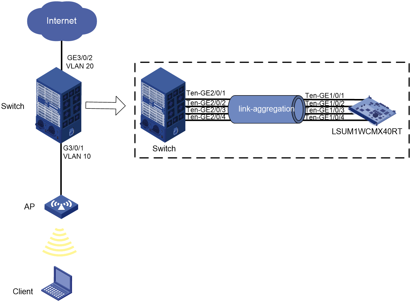
As shown in Figure 1, the modular switch is installed with an access controller module in slot 2, and the AP connects to the Internet through the switch. Configure wireless services on the access controller module for the client to access the Internet through a WLAN.
|
|
NOTE: This example uses an S7506E-X switch of Release 7180 in standalone mode and an LSUM1WCMX40RT access controller module of Release 5419. |
Analysis
To simplify deployment in a network that already has a modular switch deployed, deploy an access controller module instead of an independent AC in the network. To provide WLAN access, you must configure the following settings:
1. Configure the AP, access controller module, and switch to achieve Layer 2 connectivity. To improve link bandwidth and availability between the access controller module and the switch, assign interfaces Ten-GE2/0/1 through Ten-GE2/0/4 that connect the switch to the module to an aggregation group.
2. Enable DHCP server on the access controller module for the module to assign IP addresses to the AP and the client.
3. Configure AP authentication.
4. Configure a wireless service template for the client to access the WLAN.
Procedure
1. Configure the access controller module to communicate with the switch.
# Create VLAN 10 and VLAN 20, and assign interfaces Ten-GigabitEthernet2/0/1 through Ten-GigabitEthernet2/0/4 to aggregation group 1.
<Switch> system-view
[Switch] vlan 10
[Switch-vlan10] quit
[Switch] vlan 20
[Switch-vlan20] quit
[Switch] interface bridge-aggregation 1
[Swtich-Bridge-Aggregation1] quit
[Switch] interface ten-gigabitethernet 2/0/1
[Switch-Ten-GigabitEthernet2/0/1] port link-aggregation group 1
[Switch-Ten-GigabitEthernet2/0/1] quit
[Switch] interface ten-gigabitethernet 2/0/2
[Switch-Ten-GigabitEthernet2/0/2] port link-aggregation group 1
[Switch-Ten-GigabitEthernet2/0/2] quit
[Switch] interface ten-gigabitethernet 2/0/3
[Switch-Ten-GigabitEthernet2/0/3] port link-aggregation group 1
[Switch-Ten-GigabitEthernet2/0/3] quit
[Switch] interface ten-gigabitethernet 2/0/4
[Switch-Ten-GigabitEthernet2/0/4] port link-aggregation group 1
[Switch-Ten-GigabitEthernet2/0/4] quit
[Switch] interface bridge-aggregation 1
[Swtich-Bridge-Aggregation1] port link-type trunk
[Swtich-Bridge-Aggregation1] port trunk permit vlan 10 20
[Swtich-Bridge-Aggregation1] quit
# Configure GigabitEthernet 3/0/1 as a trunk port and assign the port to VLAN 10.
[Switch] interface gigabitethernet 3/0/1
[Swtich-GigabitEthernet3/0/1] port link-type trunk
[Swtich-GigabitEthernet3/0/1] port trunk permit vlan 10
[Swtich-GigabitEthernet3/0/1] quit
[Swtich] quit
# Log in to the CLI of the access controller module from the switch. Create a Layer 2 aggregate interface and assign interfaces Ten-GigabitEthernet 1/0/1 through Ten-GigabitEthernet 1/0/4 that connect the module to the switch to VLAN 10 and VLAN 20.
<Switch> oap connect slot 2
<AC> system-view
[AC] vlan 10
[AC-vlan10] quit
[AC] vlan 20
[AC-vlan20] quit
[AC] interface bridge-aggregation 1
[AC-Bridge-Aggregation1] port link-type trunk
[AC-Bridge-Aggregation1] port trunk permit vlan 10 20
[AC-Bridge-Aggregation1] quit
[AC] interface ten-gigabitethernet 1/0/1
[AC-Ten-GigabitEthernet1/0/1] port link-aggregation group 1
[AC-Ten-GigabitEthernet1/0/1] quit
[AC] interface ten-gigabitethernet 1/0/2
[AC-Ten-GigabitEthernet1/0/2] port link-aggregation group 1
[AC-Ten-GigabitEthernet1/0/2] quit
[AC] interface ten-gigabitethernet 1/0/3
[AC-Ten-GigabitEthernet1/0/3] port link-aggregation group 1
[AC-Ten-GigabitEthernet1/0/3] quit
[AC] interface ten-gigabitethernet 1/0/4
[AC-Ten-GigabitEthernet1/0/4] port link-aggregation group 1
[AC-Ten-GigabitEthernet1/0/4] quit
2. Configure the switch to communicate with the uplink network.
# Press Ctrl + K to return to the CLI of the switch.
# Assign GigabitEthernet 3/0/2 that connects the switch to the uplink network to VLAN 20.
<Switch> system-view
[Switch] interface gigabitethernet 3/0/2
[Swtich-GigabitEthernet3/0/2] port link-type trunk
[Swtich-GigabitEthernet3/0/2] port trunk permit vlan 20
[Swtich-GigabitEthernet3/0/2] quit
3. Configure DHCP service on the access controller module.
# Enable DHCP.
<Switch> oap connect slot 2
<AC> system-view
[AC] dhcp enable
# Specify subnet 192.168.10.0/24 and gateway address 192.168.10.1 in DHCP address pool 1.
[AC] dhcp server ip-pool 1
[AC-Server-dhcp-pool-1] network 192.168.10.0 mask 255.255.255.0
[AC-Server-dhcp-pool-1] gateway-list 192.168.10.1
[AC-Server-dhcp-pool-1] quit
# Specify subnet 192.168.20.0/24 and gateway address 192.168.20.1 in DHCP address pool 2.
[AC] dhcp server ip-pool 2
[AC-Server-dhcp-pool-2] network 192.168.20.0 mask 255.255.255.0
[AC-Server-dhcp-pool-1] gateway-list 192.168.20.1
[AC-Server-dhcp-pool-2] quit
# Create VLAN-interface 10 and VLAN-interface 20, and assign IP addresses to the interfaces.
[AC] interface vlan-interface 10
[AC-Vlan-interface10] ip address 192.168.10.1 255.255.255.0
[AC-Vlan-interface10] quit
[AC] interface vlan-interface 20
[AC-Vlan-interface20] ip address 192.168.20.1 255.255.255.0
[AC-Vlan-interface20] quit
4. Configure AP settings.
# Create AP ap1 and specify the AP model and serial number.
[AC] wlan ap ap1 model WA4320i-ACN
[AC-wlan-ap-ap1] serial-id 219801A0CNC138011454
[AC-wlan-ap-ap1] quit
5. Configure wireless services.
# Create service template service1, specify the SSID as trade-off, and assign clients coming online through the service template to VLAN 20.
[AC] wlan service-template service1
[AC-wlan-st-service1] ssid trade-off
[AC-wlan-st-service1] vlan 20
[AC-wlan-st-service1] quit
# Configure the AKM mode. This example sets the AKM mode to PSK and uses simple character string 12345678 as the PSK.
[AC-wlan-st-1] akm mode psk
[AC-wlan-st-1] preshared-key pass-phrase simple 12345678
# Specify the cipher suite as CCMP and the security IE as RSN.
[AC-wlan-st-1] cipher-suite ccmp
[AC-wlan-st-1] security-ie rsn
# Enable the service template.
[AC-wlan-st-1] service-template enable
[AC-wlan-st-1] quit
# Bind service template service1 to radio 1 of AP ap1.
[AC] wlan ap ap1
[AC-wlan-ap-ap1] radio 1
[AC-wlan-ap-ap1-radio-1] service-template service1
[AC-wlan-ap-ap1-radio-1] radio enable
[AC-wlan-ap-ap1-radio-1] quit
[AC-wlan-ap-ap1] quit
6. Verify the configuration.
# Start up the AP.
# Verify that the AP came online successfully. The AP is online if the AP state field displays R.
[AC] display wlan ap all
Total number of APs: 1
Total number of connected APs: 1
Total number of connected manual APs: 1
Total number of connected auto APs: 0
Total number of connected common APs: 1
Total number of connected WTUs: 0
Total number of inside APs: 0
Maximum supported APs: 128
Remaining APs: 127
Total AP licenses: 128
Local AP licenses: 128
Server AP licenses: 0
Remaining local AP licenses: 127
Sync AP licenses: 0
AP information
State : I = Idle, J = Join, JA = JoinAck, IL = ImageLoad
C = Config, DC = DataCheck, R = Run M = Master, B = Backup
AP name APID State Model Serial ID
ap1 1 R WA4320i-ACN 219801A0CNC138011454
# Verify that you can use password 12345678 to connect the client to WLAN trade-off.
# Verify that the client came online from AP ap1.
[AC] display wlan client
Total number of clients: 1
MAC address Username AP name RID IPv4 address VLAN
000f-e265-6400 N/A ap1 1 192.168.20.2 20