- Table of Contents
- Related Documents
-
| Title | Size | Download |
|---|---|---|
| 02-SR-TE policy configuration | 187.46 KB |
Contents
SR-TE policy routing procedure
SR-TE policy forwarding procedure
MP-BGP extension for SR-TE policy-based routing
SR-TE policy configuration tasks at a glance
Configuring SR-TE policy attributes
Configuring BGP to advertise SR-TE policy routes
Restrictions and guidelines for SR-TE policy routes advertisement
Enabling BGP to advertise SR-TE policy routes
Configuring BGP to redistribute routes from the SR-TE policy
Configuring BGP to control SR-TE policy route selection and advertisement
Configuring the SR TE forwarding statistics feature
Display and maintenance commands for SR-TE policies
SR-TE policy configuration examples
Example: Configuring SR-TE policy-based forwarding
Configuring SR-TE policies
About SR-TE policies
Segment Routing (SR) policies enable the device to flexibly steer traffic through an SR network.
SR-TE policies apply to scenarios where multiple paths exist between a source node and a destination node on an SR network.
Basic concepts
SR-TE policy identification
An SR-TE policy is identified by the following items:
· BSID—SID of the ingress node.
· Color—Color attribute for the forwarding path. You can use the color attribute to distinguish an SR-TE policy from other SR-TE policies that are configured for the same source and destination nodes.
· End point—IP address of the destination node.
Candidate path
A candidate path is a forwarding path that an SR-TE policy can use to forward packets.
An SR-TE policy can have multiple candidate paths. Two SR-TE policies cannot share the same candidate path.
Preference
Candidate paths are uniquely identified by their preference values. An SR-TE policy chooses a candidate path from all its candidate paths based on the preference values.
Segment list
A segment list is a list of SIDs that indicates a packet forwarding subpath. Each SID identifies the segment for forwarding packets to the next hop along the subpath.
A segment list is also call a SID list.
A candidate path can have a single SID list or multiple SID lists that use different weight values.
Weight
A SID list can have a weight value. After an SR-TE policy chooses a candidate path with multiple SID lists, the traffic will be load shared among the subpaths based on weight values.
SR-TE policy validity
The following describes the rules for identifying the validity of a SR-TE policy:
1. An SR-TE policy is valid only if it has valid candidate paths.
2. A candidate path is valid only if it has a valid SID list.
3. A SID list is valid if none of the following situations exists:
¡ The SID list is empty.
¡ The weight of the SID list is 0.
¡ An SR node cannot find the outgoing interface or next hop address based on the SID at the top of the SID list stack.
SR-TE policy routing procedure
The following describes how the device chooses and uses an SR-TE policy to route a packet:
1. Upon receiving a packet whose stack top label is a BSID, the device identifies the valid SR-TE policies based on the BSID.
2. If multiple valid SR-TE policies are available, the device chooses the SR-TE policy that was first bound to the BSID.
3. If the chosen SR-TE policy has multiple candidate paths, the device chooses the candidate path with the greatest preference value.
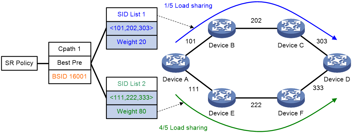
4. If the chosen candidate path has multiple SID lists, the traffic will be load shared based on the weight values among the subpaths identified by the SID lists. The load of SID list x is equal to Weight x/(Weight 1 + Weight 2 + … + Weight n).
For example, Device A in Figure 1 first chooses a valid SR-TE policy by BSID. Then, the device chooses a candidate path by preference. The candidate path has two valid SID lists: SID list 1 and SID list 2. The weight value of SID list 1 is 20 and the weight value of SID list 2 is 80. One fifth of the traffic will be forwarded through the subpath identified by SID list 1. Four fifth of the traffic will be forwarded through the subpath identified by SID list 2.
Figure 1 SR-TE policy routing diagram
SR-TE policy forwarding procedure
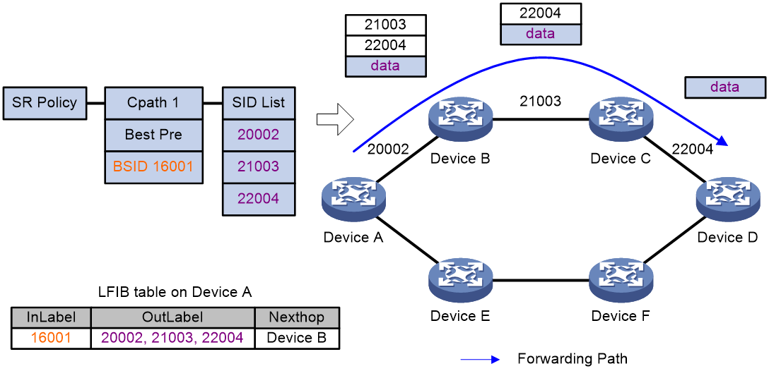
As shown in Figure 2, the SR-TE policy forwarding procedure is as follows:
1. After Device A receives a packet with the stack top label 16001, it searches its LFIB and determines that the label is a BSID. Then, Device A obtains the outgoing label stack and next hop (Device B), pops the BSID, pushes SID list {20002, 21003, 22004}, and forwards the packet to Device B. 20002 is the SID of the segment for a packet to travel from Device A to Device B. 21003 is the SID of the segment for a packet to travel from Device B to Device C. 22004 is the SID of the segment for a packet to travel from Device C to Device D.
2. After Device B receives the packet, it searches its LFIB by the incoming label and determines that the next hop is Device C. Then, Device B forwards the packet to Device C.
3. After Device C receives the packet, it searches its LFIB by the incoming label and determines that the next hop is Device D. Then, Device C forwards the packet to Device D.
4. After Device D receives the packet, it identifies whether the packet is carrying a label. If yes, Device D searches its LFIB to forward the packet. If not, Device D searches its IP FIB to forward the packet.
Figure 2 SR-TE policy forwarding diagram
MP-BGP extension for SR-TE policy-based routing
To support SR-TE policies, MP-BGP increases the following definitions:
· BGP IPv4 SR-TE policy address family.
· SR-TE policy routes, which are also called SR-TE policy NLRI.
SR-TE policy route information carries SR-TE policy settings, including the BSIDs, color values, end points, preference values, and weight values. After the device advertises SR-TE policy routes to a peer, the peer can also use SR-TE policies to steer traffic.
The device supports the color extended community attribute. Upon receiving a packet that matches a route with the color extended community attribute, the device searches for an SR-TE policy that has the same color value as the route. If an SR-TE policy is found, the device forwards the packet based on the SR-TE policy. If not, the device uses the optimal route to forward the packet.
The color extended community attribute is in the format of 2-bit Color-Only flag:32-bit user-defined color value, for example, 10:3.
SR-TE policy configuration tasks at a glance
To configure an SR-TE policy, perform the following tasks:
1. Configuring IGP-based SID advertisement
Perform this task on each SR node. For more information, see MPLS SR configuration in Segment Routing Configuration Guide.
4. Configuring SR-TE policy attributes
5. Configuring a candidate path
6. (Optional.) Configuring BGP to advertise SR-TE policy routes
a. Enabling BGP to advertise SR-TE policy routes
b. Configuring BGP to redistribute routes from the SR-TE policy
c. (Optional.) Configuring BGP to control SR-TE policy route selection and advertisement
d. (Optional.) Configuring the SR TE forwarding statistics feature
7. (Optional.) Configuring the SR TE forwarding statistics feature
Configuring a SID list
About this task
After you add nodes to a SID list, the system will sort the nodes in ascending order of node index.
Procedure
1. Enter system view.
system-view
2. Enter segment routing view.
segment-routing
3. Create and enter the SR TE view.
traffic-engineering
4. Create a SID list and enter its view.
segment-list segment-list-name
5. Add a node to the SID list.
index index-number mpls label label-value
Creating an SR-TE policy
1. Enter system view.
system-view
2. Enter segment routing view.
segment-routing
3. Enter the SR TE view.
traffic-engineering
4. Create an SR-TE policy and enter its view.
policy policy-name
Configuring SR-TE policy attributes
About this task
An SR-TE policy is identified by the following items: BSID, color, and end point. Upon receiving a packet whose stack top label is a BSID, the device chooses an SR-TE policy based on the BSID to forward the packet.
You can bind a BSID to the policy manually, or set only the color and end point attributes of the policy so the system automatically assigns a BSID to the policy. If you use both methods, the manually bound BSID takes effect.
Restrictions and guidelines
If you configure an MPLS label as the BSID but the label is not in the range of the SRGB or SRLB or is already used by a protocol, the configuration does not take effect. For more information about SRGB or SRLB, see "Configuring MPLS SR."
Each SR-TE policy must have a unique color value. However, multiple SR-TE policies can have the same end point.
Procedure
1. Enter system view.
system-view
2. Enter segment routing view.
segment-routing
3. Enter the SR TE view.
traffic-engineering
4. Enter SR-TE policy view.
policy policy-name
5. Bind a BSID to the policy.
binding-sid mpls mpls-label
6. Set the color and end point attributes.
color color-value end-point ipv4 ipv4-address
Configuring a candidate path
1. Enter system view.
system-view
2. Enter segment routing view.
segment-routing
3. Enter SR TE view.
traffic-engineering
4. Enter SR-TE policy view.
policy policy-name
5. Create and enter SR-TE policy candidate path view.
candidate-paths
6. Set the preference for a candidate path and enter candidate path preference view.
preference preference-value
By default, no candidate path preferences are set.
Each preference represents a candidate path.
7. Specify an explicit path for the candidate path.
explicit segment-list segment-list-name [ weight weight-value ]
A candidate path can have multiple SID lists.
Configuring BGP to advertise SR-TE policy routes
Restrictions and guidelines for SR-TE policy routes advertisement
For more information about BGP commands, see Layer 3—IP Routing Commands.
Enabling BGP to advertise SR-TE policy routes
1. Enter system view.
system-view
2. Configure a global router ID.
router id router-id
By default, no global router ID is configured.
3. Enable a BGP instance and enter its view.
bgp as-number [ instance instance-name ]
By default, BGP is disabled and no BGP instances exist.
4. Configure a peer.
peer { group-name | ipv4-address [ mask-length ] } as-number as-number
5. Create the BGP IPv4 SR-TE policy address family and enter its view.
address-family ipv4 sr-policy
6. Enable BGP to exchange SR-TE policy routing information with the peer or peer group.
peer { group-name | ipv4-address [ mask-length ] } enable
By default, the device cannot use BGP to exchange SR-TE policy routing information with a peer or peer group.
Configuring BGP to redistribute routes from the SR-TE policy
About this task
After you configure BGP to redistribute SR-TE policy routes, the system will redistribute the local SR-TE policy routes to the BGP routing table and advertise the routes to peers. Then, the peers can forward traffic based on the SR-TE policy.
Procedure
1. Enter system view.
system-view
2. Enter BGP instance view.
bgp as-number [ instance instance-name ]
3. Enter BGP IPv4 SR-TE policy address family view.
address-family ipv4 sr-policy
4. Enable BGP to redistribute routes from the SR-TE policy.
import-route sr-policy
By default, BGP does not redistribute SR-TE policy routes.
Configuring BGP to control SR-TE policy route selection and advertisement
1. Enter system view.
system-view
2. Enter BGP instance view.
bgp as-number [ instance instance-name ]
3. Enter BGP IPv4 SR-TE policy address family view.
address-family ipv4 sr-policy
4. Specify the local router as the next hop for routes sent to a peer or peer group.
peer { group-name | ipv4-address [ mask-length ] } next-hop-local
By default, BGP sets the local router as the next hop for all routes sent to an EBGP peer or peer group. BGP does not set the local router as the next hop for routes sent to an IBGP peer or peer group.
5. Allow a local AS number to exist in the AS_PATH attribute of routes from a peer or peer group, and to set the number of times the local AS number can appear.
peer { group-name | ipv4-address [ mask-length ] } allow-as-loop [ number ]
By default, the local AS number is not allowed to exist in the AS_PATH attribute of routes from a peer or peer group.
6. Specify a preferred value for routes received from a peer or peer group.
peer { group-name | ipv4-address [ mask-length ] } preferred-value value
By default, the preferred value is 0 for routes received from a peer or peer group.
7. Set the maximum number of routes that can be received from a peer or peer group.
peer { group-name | ipv4-address [ mask-length ] } route-limit prefix-number [ { alert-only | discard | reconnect reconnect-time } | percentage-value ] *
By default, the number of routes that can be received from a peer or peer group is not limited.
8. Configure the device as a route reflector and specify a peer or peer group as a client.
peer { group-name | ipv4-address [ mask-length ] } reflect-client
By default, neither the route reflector nor the client is configured.
9. Specify a prefix list to filter routes received from or advertised to a peer or peer group.
peer { group-name | ipv4-address [ mask-length ] } prefix-list ipv4-prefix-list-name { export | import }
By default, no prefix list based filtering is configured.
10. Apply a routing policy to routes incoming from or outgoing to a peer or peer group.
peer { group-name | ipv4-address [ mask-length ] } route-policy route-policy-name { export | import }
By default, no routing policy is applied to routes incoming from or outgoing to a peer or peer group.
11. Advertise the COMMUNITY attribute to a peer or peer group.
peer { group-name | ipv4-address [ mask-length ] } advertise-community
By default, no COMMUNITY attribute is advertised to any peers or peer groups.
12. Advertise the extended community attribute to a peer or peer group.
peer { group-name | ipv4-address [ mask-length ] } advertise-ext-community
By default, no extended community attribute is advertised to any peers or peer groups.
Maintaining BGP sessions
To maintain BGP sessions, execute the following commands in user view:
· Reset BGP sessions for the BGP IPv4 SR-TE policy address family.
reset bgp [ instance instance-name ] { as-number | ipv4-address [ mask-length ] | all | external | group group-name | internal } ipv4 sr-policy
· Manually soft-reset BGP sessions for the BGP IPv4 SR-TE policy address family.
refresh bgp [ instance instance-name ] { ipv4-address [ mask-length ] | all | external | group group-name | internal } { export | import } ipv4 sr-policy
Configuring the SR TE forwarding statistics feature
About the SR TE forwarding statistics feature
The SR TE forwarding statistics feature collects statistics on traffic forwarded by SR-TE policies.
Procedure
1. Enter system view.
system-view
2. Enter segment routing view.
segment-routing
3. Enter SR TE view.
traffic-engineering
4. Enable SR TE forwarding statistics.
forwarding statistics enable
By default, SR TE forwarding statistics is disabled.
5. (Optional.) Set the SR TE forwarding statistics interval.
forwarding statistics interval interval
By default, the SR TE forwarding statistics interval is 30 seconds.
Display and maintenance commands for SR-TE policies
Execute display commands in any view. Execute reset commands in user view.
|
Task |
Command |
|
Display BGP peer or peer group information. |
display bgp [ instance instance-name ] peer ipv4 sr-policy [ ipv4-address mask-length | { ipv4-address | group-name group-name } log-info | [ ipv4-address ] verbose ] |
|
Display BGP IPv4 SR-TE policy routing information. |
display bgp [ instance instance-name ] routing-table ipv4 sr-policy [ sr-policy-prefix [ advertise-info ] | peer ipv4-address { advertised-routes | received-routes } [ statistics ] | statistics ] |
|
Display SR TE forwarding information. |
display segment-routing te forwarding [ policy { policy-name | { color color-value | end-point ipv4 ip-address } * } ] [ verbose ] |
|
Display SR TE policy information. |
display segment-routing te policy [ policy-name | down | up | { color color-value | end-point ipv4 ip-address } * ] |
|
Display SR-TE policy statistics. |
display segment-routing te policy statistics |
|
Display SR-TE SID list information. |
display segment-routing te segment-list [ name segment-list-name | id id-value ] |
|
Clear SR TE forwarding statistics. |
reset segment-routing te forwarding statistics |
SR-TE policy configuration examples
Example: Configuring SR-TE policy-based forwarding
Network configuration
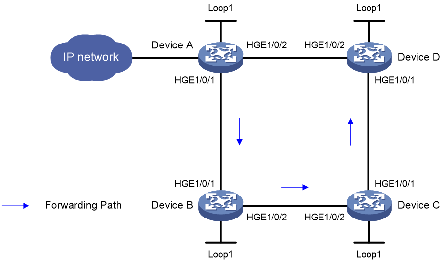
As shown in Figure 3, perform the following tasks on the devices to implement SR-TE policy-based forwarding:
· Configure Device A through Device D to run IS-IS to implement Layer 3 connectivity.
· Configure MPLS SR on Device A through Device D to establish an SRLSP.
· Configure an SR-TE policy on Device A to forward user packets along path Device A > Device B > Device C > Device D.
|
Device |
Interface |
IP address |
Device |
Interface |
IP address |
|
Device A |
Loop1 |
1.1.1.1/32 |
Device B |
Loop1 |
2.2.2.2/32 |
|
|
HGE1/0/1 |
12.0.0.1/24 |
|
HGE1/0/1 |
12.0.0.2/24 |
|
|
HGE1/0/2 |
14.0.0.1/24 |
|
HGE1/0/2 |
23.0.0.2/24 |
|
Device C |
Loop1 |
3.3.3.3/32 |
Device D |
Loop1 |
4.4.4.4/32 |
|
|
HGE1/0/1 |
34.0.0.3/24 |
|
HGE1/0/1 |
34.0.0.4/24 |
|
|
HGE1/0/2 |
23.0.0.3/24 |
|
HGE1/0/2 |
14.0.0.4/24 |
Procedure
|
|
IMPORTANT: By default, interfaces on the device are disabled (in ADM or Administratively Down state). To have an interface operate, you must use the undo shutdown command to enable that interface. |
1. Configure IP addresses and masks for interfaces. (Details not shown.)
2. Configure IS-IS on the devices and set the IS-IS cost style to wide:
# Configure Device A.
<DeviceA> system-view
[DeviceA] isis 1
[DeviceA-isis-1] network-entity 00.0000.0000.0001.00
[DeviceA-isis-1] cost-style wide
[DeviceA-isis-1] quit
[DeviceA] interface hundredgige 1/0/1
[DeviceA-HundredGigE1/0/1] isis enable 1
[DeviceA-HundredGigE1/0/1] quit
[DeviceA] interface hundredgige 1/0/2
[DeviceA-HundredGigE1/0/2] isis enable 1
[DeviceA-HundredGigE1/0/2] quit
[DeviceA] interface loopback 1
[DeviceA-LoopBack1] isis enable 1
[DeviceA-LoopBack1] quit
# Configure Device B.
<DeviceB> system-view
[DeviceB] isis 1
[DeviceB-isis-1] network-entity 00.0000.0000.0002.00
[DeviceB-isis-1] cost-style wide
[DeviceB-isis-1] quit
[DeviceB] interface hundredgige 1/0/1
[DeviceB-HundredGigE1/0/1] isis enable 1
[DeviceB-HundredGigE1/0/1] quit
[DeviceB] interface hundredgige 1/0/2
[DeviceB-HundredGigE1/0/2] isis enable 1
[DeviceB-HundredGigE1/0/2] quit
[DeviceB] interface loopback 1
[DeviceB-LoopBack1] isis enable 1
[DeviceB-LoopBack1] quit
# Configure Device C.
<DeviceC> system-view
[DeviceC] isis 1
[DeviceC-isis-1] network-entity 00.0000.0000.0003.00
[DeviceC-isis-1] cost-style wide
[DeviceC-isis-1] quit
[DeviceC] interface hundredgige 1/0/1
[DeviceC-HundredGigE1/0/1] isis enable 1
[DeviceC-HundredGigE1/0/1] quit
[DeviceC] interface hundredgige 1/0/2
[DeviceC-HundredGigE1/0/2] isis enable 1
[DeviceC-HundredGigE1/0/2] quit
[DeviceC] interface loopback 1
[DeviceC-LoopBack1] isis enable 1
[DeviceC-LoopBack1] quit
# Configure Device D.
<DeviceD> system-view
[DeviceD] isis 1
[DeviceD-isis-1] network-entity 00.0000.0000.0004.00
[DeviceD-isis-1] cost-style wide
[DeviceD-isis-1] quit
[DeviceD] interface hundredgige 1/0/1
[DeviceD-HundredGigE1/0/1] isis enable 1
[DeviceD-HundredGigE1/0/1] quit
[DeviceD] interface hundredgige 1/0/2
[DeviceD-HundredGigE1/0/2] isis enable 1
[DeviceD-HundredGigE1/0/2] quit
[DeviceD] interface loopback 1
[DeviceD-LoopBack1] isis enable 1
[DeviceD-LoopBack1] quit
3. Configure MPLS LSR IDs, and enable MPLS and MPLS TE:
# Configure Device A.
[DeviceA] mpls lsr-id 1.1.1.1
[DeviceA] mpls te
[DeviceA-te] quit
[DeviceA] interface hundredgige 1/0/1
[DeviceA-HundredGigE1/0/1] mpls enable
[DeviceA-HundredGigE1/0/1] quit
[DeviceA] interface hundredgige 1/0/2
[DeviceA-HundredGigE1/0/2] mpls enable
[DeviceA-HundredGigE1/0/2] quit
# Configure Device B.
[DeviceB] mpls lsr-id 2.2.2.2
[DeviceB] mpls te
[DeviceB-te] quit
[DeviceB] interface hundredgige 1/0/1
[DeviceB-HundredGigE1/0/1] mpls enable
[DeviceB-HundredGigE1/0/1] quit
[DeviceB] interface hundredgige 1/0/2
[DeviceB-HundredGigE1/0/2] mpls enable
[DeviceB-HundredGigE1/0/2] quit
# Configure Device C.
[DeviceC] mpls lsr-id 3.3.3.3
[DeviceC] mpls te
[DeviceC-te] quit
[DeviceC] interface hundredgige 1/0/1
[DeviceC-HundredGigE1/0/1] mpls enable
[DeviceC-HundredGigE1/0/1] quit
[DeviceC] interface hundredgige 1/0/2
[DeviceC-HundredGigE1/0/2] mpls enable
[DeviceC-HundredGigE1/0/2] quit
# Configure Device D.
[DeviceD] mpls lsr-id 4.4.4.4
[DeviceD] mpls te
[DeviceD-te] quit
[DeviceD] interface hundredgige 1/0/1
[DeviceD-HundredGigE1/0/1] mpls enable
[DeviceD-HundredGigE1/0/1] quit
[DeviceD] interface hundredgige 1/0/2
[DeviceD-HundredGigE1/0/2] mpls enable
[DeviceD-HundredGigE1/0/2] quit
4. Configure SRGBs and enable MPLS SR in IPv4 unicast address family view:
# Configure Device A.
[DeviceA] isis 1
[DeviceA-isis-1] segment-routing global-block 16000 16999
[DeviceA-isis-1] address-family ipv4
[DeviceA-isis-1-ipv4] segment-routing mpls
[DeviceA-isis-1-ipv4] quit
[DeviceA-isis-1] quit
# Configure Device B.
[DeviceB] isis 1
[DeviceB-isis-1] segment-routing global-block 17000 17999
[DeviceB-isis-1] address-family ipv4
[DeviceB-isis-1-ipv4] segment-routing mpls
[DeviceB-isis-1-ipv4] quit
[DeviceB-isis-1] quit
# Configure Device C.
[DeviceC] isis 1
[DeviceC-isis-1] segment-routing global-block 18000 18999
[DeviceC-isis-1] address-family ipv4
[DeviceC-isis-1-ipv4] segment-routing mpls
[DeviceC-isis-1-ipv4] quit
[DeviceC-isis-1] quit
# Configure Device D.
[DeviceD] isis 1
[DeviceD-isis-1] segment-routing global-block 19000 19999
[DeviceD-isis-1] address-family ipv4
[DeviceD-isis-1-ipv4] segment-routing mpls
[DeviceD-isis-1-ipv4] quit
[DeviceD-isis-1] quit
5. Configure IS-IS prefix SIDs:
# Configure Device A.
[DeviceA] interface loopback 1
[DeviceA-LoopBack1] isis prefix-sid index 10
[DeviceA-LoopBack1] quit
# Configure Device B.
[DeviceB] interface loopback 1
[DeviceB-LoopBack1] isis prefix-sid index 20
[DeviceB-LoopBack1] quit
# Configure Device C.
[DeviceC] interface loopback 1
[DeviceC-LoopBack1] isis prefix-sid index 30
[DeviceC-LoopBack1] quit
# Configure Device D.
[DeviceD] interface loopback 1
[DeviceD-LoopBack1] isis prefix-sid index 40
[DeviceD-LoopBack1] quit
6. Configure an SID list on Device A.
[DeviceA] segment-routing
[DeviceA-segment-routing] traffic-engineering
[DeviceA-sr-te] segment-list s1
[DeviceA-sr-te-sl-s1] index 10 mpls label 16020
[DeviceA-sr-te-sl-s1] index 20 mpls label 17030
[DeviceA-sr-te-sl-s1] index 30 mpls label 18040
[DeviceA-sr-te-sl-s1] quit
7. Create an SR-TE policy and set the attributes on Device A.
[DeviceA-sr-te] policy p1
[DeviceA-sr-te-policy-p1] binding-sid mpls 15000
[DeviceA-sr-te-policy-p1] color 10 end-point ipv4 4.4.4.4
8. Configure a candidate path for the SR-TE policy and specify an explicit path for the candidate path.
[DeviceA-sr-te-policy-p1] candidate-paths
[DeviceA-sr-te-policy-p1-path] preference 10
[DeviceA-sr-te-policy-p1-path-pref-10] explicit segment-list s1
[DeviceA-sr-te-policy-p1-path-pref-10] quit
[DeviceA-sr-te-policy-p1-path] quit
[DeviceA-sr-te-policy-p1] quit
[DeviceA-sr-te] quit
[DeviceA-segment-routing] quit
Verifying the configuration
# Display SR TE policy information on Device A.
[DeviceA] display segment-routing te policy
Name/ID: p1/0
Color: 10
Endpoint: 4.4.4.4
BSID:
Mode: EXPLICIT Type: TYPE_1 Request state: SUCCESS
Current BSID: 15000 Explicit BSID: 15000 Dynamic BSID: -
Reference counts: 3
Flags: A/BS
Status: Up
Up/Down date: 2019-06-28 15:17:50
Candidate paths state: Configured
Candidate paths:
Preference : 10
Instance ID: 0 ASN: 0 Node Address: 0.0.0.0
Optimal: Y Flags: V/A
Explict SID list:
ID: 1 Name: s1
Weight: 1
The output shows that the SR-TE policy is in up state. The device can use the SR-TE policy to forward packets.
# Display SR TE forwarding information on Device A.
[DeviceA] display segment-routing te forwarding verbose
Total Forwarding entries: 1
SR TE policy name/ID: p1/0
BSID: 15000
SegList name/ID: s1/1
NID: 0x01400001
Outlabel: 3
Interface: HGE1/0/1
Nexthop: 12.0.0.2
Path-id: 1
Weight: 1
Label stack: {17030, 18040}
The output shows that the label stack for packets forwarded by using the SR-TE policy is {17030, 18040}.
# Display MPLS LSP information on Device A.
[DeviceA] display mpls lsp
FEC Proto In/Out Label Out Inter/NHLFE/LSINDEX
12.0.0.2 Local -/- HGE1/0/1
14.0.0.4 Local -/- HGE1/0/2
1.1.1.1/32 ISIS 16010/- -
2.2.2.2/32 ISIS 16020/3 HGE1/0/1
2.2.2.2/32 ISIS -/3 HGE1/0/1
3.3.3.3/32 ISIS 16030/17030 HGE1/0/1
3.3.3.3/32 ISIS -/17030 HGE1/0/1
3.3.3.3/32 ISIS 16030/19030 HGE1/0/2
3.3.3.3/32 ISIS -/19030 HGE1/0/2
4.4.4.4/32 ISIS 16040/3 HGE1/0/2
4.4.4.4/32 ISIS -/3 HGE1/0/2
4.4.4.4/32/20971521 SRPolicy -/17030 HGE1/0/1
18040
4.4.4.4/10 SRPolicy 15000/- LSINDEX20971521
The output shows that the forwarding paths used by the SR-TE policy.