- Table of Contents
-
- 03-Layer 3-IP Services Configuration Guide
- 00-Preface
- 01-ARP configuration
- 02-IP addressing configuration
- 03-DHCP configuration
- 04-DNS configuration
- 05-IP forwarding basics configuration
- 06-Fast forwarding configuration
- 07-Adjacency table configuration
- 08-IRDP configuration
- 09-IP performance optimization configuration
- 10-UDP helper configuration
- 11-IPv6 basics configuration
- 12-DHCPv6 configuration
- 13-IPv6 fast forwarding configuration
- 14-Tunneling configuration
- 15-GRE configuration
- Related Documents
-
| Title | Size | Download |
|---|---|---|
| 01-ARP configuration | 328.79 KB |
Configuring a static ARP entry
Configuring a short static ARP entry
Configuring a long static ARP entry
Configuring dynamic ARP entry features
Setting the dynamic ARP learning limit for a device
Setting the dynamic ARP learning limit for an interface
Setting the aging timer for dynamic ARP entries
Enabling dynamic ARP entry check
Setting the ARP hardware resource mode
Performing ARP entry synchronization
Configuring a customer-side or network-side port
Enabling an IP unnumbered interface to learn ARP entries for different subnets
Display and maintenance commands for ARP
Example: Configuring a long static ARP entry
Example: Configuring a short static ARP entry
Gratuitous ARP packet learning
Periodic sending of gratuitous ARP packets
Gratuitous ARP tasks at a glance
Enabling IP conflict notification
Enabling gratuitous ARP packet learning
Enabling periodic sending of gratuitous ARP packets
Display and maintenance commands for proxy ARP
Proxy ARP configuration examples
Example: Configuring common proxy ARP
Creation of ARP snooping entries
Display and maintenance commands for ARP snooping
ARP fast-reply configuration examples
Example: Configuring ARP fast-reply
Enabling ARP suppression for a cross-connect group
Enabling ARP suppression for a VSI
Display and maintenance commands for ARP suppression
ARP suppression configuration examples
Example: Configuring ARP suppression
Configuring ARP direct route advertisement
About ARP direct route advertisement
Mechanism of ARP direct route advertisement
Application in Layer 3 access networks
Enabling ARP direct route advertisement
Configuring ARP
About ARP
ARP resolves IP addresses into MAC addresses on Ethernet networks.
ARP message format
ARP uses two types of messages: ARP request and ARP reply. Figure 1 shows the format of ARP request/reply messages. Numbers in the figure refer to field lengths.
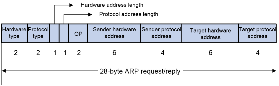
· Hardware type—Hardware address type. The value 1 represents Ethernet.
· Protocol type—Type of the protocol address to be mapped. The hexadecimal value 0x0800 represents IP.
· Hardware address length and protocol address length—Length, in bytes, of a hardware address and a protocol address. For an Ethernet address, the value of the hardware address length field is 6. For an IPv4 address, the value of the protocol address length field is 4.
· OP—Operation code, which describes the type of ARP message. The value 1 represents an ARP request, and the value 2 represents an ARP reply.
· Sender hardware address—Hardware address of the device sending the message.
· Sender protocol address—Protocol address of the device sending the message.
· Target hardware address—Hardware address of the device to which the message is being sent.
· Target protocol address—Protocol address of the device to which the message is being sent.
ARP operating mechanism
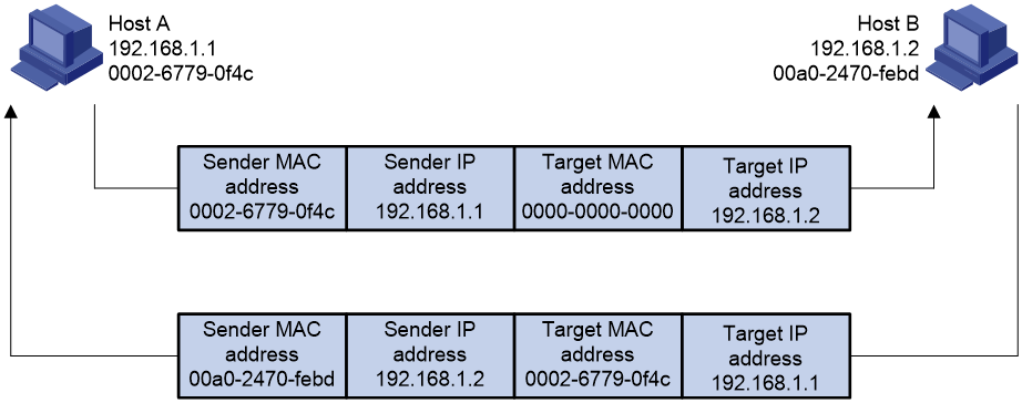
As shown in Figure 2, Host A and Host B are on the same subnet. Host A sends a packet to Host B as follows:
1. Host A looks through the ARP table for an ARP entry for Host B. If one entry is found, Host A uses the MAC address in the entry to encapsulate the IP packet into a data link layer frame. Then Host A sends the frame to Host B.
2. If Host A finds no entry for Host B, Host A buffers the packet and broadcasts an ARP request. The payload of the ARP request contains the following information:
¡ Sender IP address and sender MAC address—Host A's IP address and MAC address.
¡ Target IP address—Host B's IP address.
¡ Target MAC address—An all-zero MAC address.
All hosts on this subnet can receive the broadcast request, but only the requested host (Host B) processes the request.
3. Host B compares its own IP address with the target IP address in the ARP request. If they are the same, Host B operates as follows:
a. Adds the sender IP address and sender MAC address into its ARP table.
b. Encapsulates its MAC address into an ARP reply.
c. Unicasts the ARP reply to Host A.
4. After receiving the ARP reply, Host A operates as follows:
a. Adds the MAC address of Host B into its ARP table.
b. Encapsulates the MAC address into the packet and sends the packet to Host B.
Figure 2 ARP address resolution process
If Host A and Host B are on different subnets, Host A sends a packet to Host B as follows:
1. Host A broadcasts an ARP request where the target IP address is the IP address of the gateway.
2. The gateway responds with its MAC address in an ARP reply to Host A.
3. Host A uses the gateway's MAC address to encapsulate the packet, and then sends the packet to the gateway.
4. If the gateway has an ARP entry for Host B, it forwards the packet to Host B directly. If not, the gateway broadcasts an ARP request, in which the target IP address is the IP address of Host B.
5. After the gateway gets the MAC address of Host B, it sends the packet to Host B.
ARP entry types
An ARP table stores dynamic, static, OpenFlow, and Rule ARP entries.
Dynamic ARP entry
ARP automatically creates and updates dynamic entries. A dynamic ARP entry is removed when its aging timer expires or the output interface goes down. In addition, a dynamic ARP entry can be overwritten by a static ARP entry.
Static ARP entry
A static ARP entry is manually configured and maintained. It does not age out and cannot be overwritten by any dynamic ARP entry.
Static ARP entries protect communication between devices because attack packets cannot modify the IP-to-MAC mapping in a static ARP entry.
The device supports the following types of static ARP entries:
· Long static ARP entry—It is directly used for forwarding packets. A long static ARP entry contains the IP address, MAC address, and one of the following combinations:
¡ VLAN and output interface.
¡ Input and output interfaces.
· Short static ARP entry—It contains only the IP address and MAC address.
¡ If the output interface is a Layer 3 Ethernet interface, the short ARP entry can be directly used to forward packets.
¡ If the output interface is a VLAN interface, the device sends an ARP request whose target IP address is the IP address in the short entry. If the sender IP and MAC addresses in the received ARP reply match the short static ARP entry, the device performs the following operations:
- Adds the interface that received the ARP reply to the short static ARP entry.
- Uses the resolved short static ARP entry to forward IP packets.
To communicate with a host by using a fixed IP-to-MAC mapping, configure a short static ARP entry on the device. To communicate with a host by using a fixed IP-to-MAC mapping through an interface in a VLAN, configure a long static ARP entry on the device.
OpenFlow ARP entry
ARP creates OpenFlow ARP entries by learning from the OpenFlow module. An OpenFlow ARP entry does not age out, and it cannot be updated. An OpenFlow ARP entry can be used directly to forward packets. For more information about OpenFlow, see OpenFlow Configuration Guide.
Rule ARP entry
ARP creates Rule ARP entries by learning from the VXLAN and OVSDB modules. A Rule ARP entry does not age out, and it cannot be updated. It can be overwritten by a static ARP entry. A Rule ARP entry can be used directly to forward packets.
For more information about VXLAN and OVSDB, see VXLAN Configuration Guide.
ARP tasks at a glance
All ARP tasks are optional.
· Configuring a static ARP entry
¡ Configuring a short static ARP entry
¡ Configuring a long static ARP entry
· Configuring dynamic ARP entry features
¡ Setting the dynamic ARP learning limit for a device
¡ Setting the dynamic ARP learning limit for an interface
¡ Setting the aging timer for dynamic ARP entries
¡ Enabling dynamic ARP entry check
· Setting the ARP hardware resource mode
· Performing ARP entry synchronization
· Configuring a customer-side or network-side port
· Enabling an IP unnumbered interface to learn ARP entries for different subnets
Configuring a static ARP entry
Static ARP entries are effective when the device functions correctly.
Configuring a short static ARP entry
Restrictions and guidelines
A resolved short static ARP entry becomes unresolved upon certain events, for example, when the resolved output interface goes down, or the corresponding VLAN or VLAN interface is deleted.
Procedure
1. Enter system view.
system-view
2. Configure a short static ARP entry.
arp static ip-address mac-address [ vpn-instance vpn-instance-name ]
Configuring a long static ARP entry
About this task
Long static ARP entries can be effective or ineffective. Ineffective long static ARP entries cannot be used for packet forwarding. A long static ARP entry is ineffective when any of the following conditions exists:
· The IP address in the entry conflicts with a local IP address.
· No local interface has an IP address in the same subnet as the IP address in the ARP entry.
A long static ARP entry for a VLAN is deleted if the VLAN or VLAN interface is deleted.
Procedure
1. Enter system view.
system-view
2. Configure a static ARP entry.
arp static ip-address mac-address [ vlan-id interface-type interface-number | vsi-interface vsi-interface-id tunnel number vsi vsi-name | vsi-interface vsi-interface-id interface-type interface-number service-instance instance-id vsi vsi-name ] [ vpn-instance vpn-instance-name ]
Configuring dynamic ARP entry features
Setting the dynamic ARP learning limit for a device
About this task
A device can dynamically learn ARP entries. To prevent a device from holding too many ARP entries, you can set the maximum number of dynamic ARP entries that the device can learn. When the limit is reached, the device stops ARP learning.
If you set a value lower than the number of existing dynamic ARP entries, the device does not delete the existing entries unless they age out.
Procedure
1. Enter system view.
system-view
2. Set the dynamic ARP learning limit for the device.
arp max-learning-number max-number slot slot-number
By default, the dynamic ARP learning limit equals to the ARP table capacity set by using the hardware-resource arp command.
To disable the device from dynamic ARP learning, set the value to 0.
Setting the dynamic ARP learning limit for an interface
About this task
An interface can dynamically learn ARP entries. To prevent an interface from holding too many ARP entries, you can set the maximum number of dynamic ARP entries that the interface can learn. When the limit is reached, the interface stops ARP learning.
You can set limits for both a Layer 2 interface and the VLAN interface for a permitted VLAN on the Layer 2 interface. The Layer 2 interface learns an ARP entry only when neither limit is reached.
The total dynamic ARP learning limit for all interfaces will not be higher than the dynamic ARP learning limit for the device.
Procedure
1. Enter system view.
system-view
2. Enter interface view.
interface interface-type interface-number
3. Set the dynamic ARP learning limit for the interface.
arp max-learning-num max-number
By default, the dynamic ARP learning limit equals to the ARP table capacity set by using the hardware-resource arp command.
To disable the interface from dynamic ARP learning, set the value to 0.
Setting the aging timer for dynamic ARP entries
About this task
Each dynamic ARP entry in the ARP table has a limited lifetime, called an aging timer. The aging timer of a dynamic ARP entry is reset each time the dynamic ARP entry is updated. A dynamic ARP entry that is not updated before its aging timer expires is deleted from the ARP table.
Procedure
1. Enter system view.
system-view
2. Set the aging timer for dynamic ARP entries.
arp timer aging aging-time
The default setting is 20 minutes.
Enabling dynamic ARP entry check
About this task
The dynamic ARP entry check feature disables the device from supporting dynamic ARP entries that contain multicast MAC addresses. The device cannot learn dynamic ARP entries containing multicast MAC addresses. You cannot manually add static ARP entries containing multicast MAC addresses.
When dynamic ARP entry check is disabled, ARP entries containing multicast MAC addresses are supported. The device can learn dynamic ARP entries containing multicast MAC addresses obtained from the ARP packets sourced from a unicast MAC address. You can also manually add static ARP entries containing multicast MAC addresses.
Procedure
1. Enter system view.
system-view
2. Enable dynamic ARP entry check.
arp check enable
By default, dynamic ARP entry check is enabled.
Setting the ARP hardware resource mode
About this mode
Hardware resources are limited on the device. ARP entries occupy device hardware resourcesYou can set the ARP hardware resource mode as needed:
· Normal mode—The number of ARP hardware entries allowed to be created is relatively small. This mode occupies fewer hardware resources.
· Enhanced mode—The number of ARP hardware entries allowed to be created is relatively large. This mode occupies more hardware resources.
Procedure
1. Enter system view.
system-view
2. Set the ARP hardware resource mode.
hardware-resource arp { normal | enhance_arp }
By default, the ARP hardware resource mode is normal.
Performing ARP entry synchronization
About this task
This task ensures that all cards on the device have the same ARP entries.
Restrictions and guidelines
To synchronize ARP entries across all cards in a timely manner, you can schedule the device to automatically execute the arp smooth command. For information about scheduling a task, see the device management in Fundamentals Configuration Guide.
Procedure
To synchronize ARP entries from the active MPU to all other cards, execute the following command in user view:
arp smooth
Configuring a customer-side or network-side port
About this task
The device generates a host route when it learns an ARP entry from a network-side port. To save hardware resources, you can specify a port that connects to a user terminal as a customer-side port. The device will not generate a host route for the learned ARP entry of the user terminal.
Procedure
1. Enter system view.
system-view
2. Enter interface view.
interface interface-type interface-number
3. Configure the interface as a customer-side port or a network-side port.
¡ Configure the interface as a customer-side port.
arp mode uni
¡ Configure the interface as a network-side port.
undo arp mode uni
By default, a port operates as a network-side port.
Enabling an IP unnumbered interface to learn ARP entries for different subnets
About this task
An IP unnumbered interface cannot learn the ARP entry of the peer device if the unnumbered interface and the peer device are on different subnets. To ensure communication between them, you can enable this feature on the IP unnumbered interface.
If an IP unnumbered interface is disabled from learning ARP entries for different subnets, existing ARP entries learned for different subnets are deleted after they age out.
Procedure
1. Enter system view.
system-view
2. Enter interface view.
interface interface-type interface-number
3. Configure the interface to borrow the IP address of the specified interface.
ip address unnumbered interface interface-type interface-number
By default, the interface does not borrow IP addresses from other interfaces.
4. Enable the IP unnumbered interface to learn ARP entries for different subnets.
arp ip-unnumbered learning enable
By default, an IP unnumbered interface cannot learn ARP entries for different subnets.
Enabling ARP logging
About this task
This feature enables a device to log ARP events when ARP cannot resolve IP addresses correctly. The device can log the following ARP events:
· On a proxy ARP-disabled interface, the target IP address of a received ARP packet is not one of the following IP addresses:
¡ The IP address of the receiving interface.
¡ The virtual IP address of the VRRP group.
· The sender IP address of a received ARP reply conflicts with one of the following IP addresses:
¡ The IP address of the receiving interface.
¡ The virtual IP address of the VRRP group.
The device sends ARP log messages to the information center. You can use the info-center source command to specify the log output rules for the information center. For more information about information center, see Network Management and Monitoring Configuration Guide.
Procedure
1. Enter system view.
system-view
2. Enable ARP logging.
arp check log enable
By default, ARP logging is disabled.
Display and maintenance commands for ARP
|
|
IMPORTANT: Clearing ARP entries from the ARP table might cause communication failures. Make sure the entries to be cleared do not affect current communications. |
Execute display commands in any view and reset commands in user view.
|
Task |
Command |
|
Display ARP entries. |
display arp [ [ all | dynamic | static ] [ slot slot-number ] | vlan vlan-id | interface interface-type interface-number ] [ count | verbose ] |
|
Display the ARP entry for an IP address. |
display arp ip-address [ slot slot-number ] [ verbose ] |
|
Display the maximum number of ARP entries that a device supports. |
display arp entry-limit |
|
Display the ARP entries for a VPN instance. |
display arp vpn-instance vpn-instance-name [ count ] |
|
Display the aging timer of dynamic ARP entries. |
display arp timer aging |
|
Display ARP hardware resource mode information. |
display hardware-resource [ arp ] |
|
Clear ARP safe-guard statistics. |
reset arp safe-guard statistics { all | slot slot-number } |
ARP configuration examples
Example: Configuring a long static ARP entry
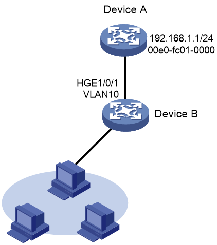
Network configuration
As shown in Figure 3, hosts are connected to Device B. Device B is connected to Device A through interface HundredGigE 1/0/1 in VLAN 10.
To ensure secure communications between Device A and Device B, configure a long static ARP entry for Device A on Device B.
Procedure
|
|
IMPORTANT: · By default, interfaces on the device are disabled (in ADM or Administratively Down state). To have an interface operate, you must use the undo shutdown command to enable that interface. · Physical interfaces in this example must operate in Layer 2 mode. By default, physical interfaces on the device operate in Layer 3 mode. To change the operation mode for physical interfaces, you must use the port link-mode command in interface view. |
# Create VLAN 10.
<DeviceB> system-view
[DeviceB] vlan 10
[DeviceB-vlan10] quit
# Add interface HundredGigE 1/0/1 to VLAN 10.
[DeviceB] interface hundredgige 1/0/1
[DeviceB-HundredGigE1/0/1] port access vlan 10
[DeviceB-HundredGigE1/0/1] quit
# Create VLAN-interface 10 and configure its IP address.
[DeviceB] interface vlan-interface 10
[DeviceB-vlan-interface10] ip address 192.168.1.2 8
[DeviceB-vlan-interface10] quit
# Configure a long static ARP entry that has IP address 192.168.1.1, MAC address 00e0-fc01-0000, and output interface HundredGigE 1/0/1 in VLAN 10.
[DeviceB] arp static 192.168.1.1 00e0-fc01-0000 10 hundredgige 1/0/1
Verifying the configuration
# Verify that Device B has a long static ARP entry for Device A.
[DeviceB] display arp static
Type: S-Static D-Dynamic O-Openflow R-Rule M-Multiport I-Invalid
IP address MAC address VLAN/VSI name Interface Aging Type
192.168.1.1 00e0-fc01-0000 10 HGE1/0/1 -- S
Example: Configuring a short static ARP entry
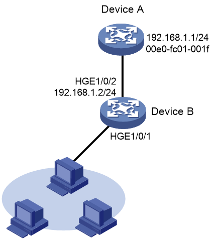
Network configuration
As shown in Figure 4, hosts are connected to Device B. Device B is connected to Device A through interface HundredGigE 1/0/2.
To ensure secure communications between Device A and Device B, configure a short static ARP entry for Device A on Device B.
Procedure
|
|
IMPORTANT: · By default, interfaces on the device are disabled (in ADM or Administratively Down state). To have an interface operate, you must use the undo shutdown command to enable that interface. · Physical interfaces in this example must operate in Layer 2 mode. By default, physical interfaces on the device operate in Layer 3 mode. To change the operation mode for physical interfaces, you must use the port link-mode command in interface view. |
# Configure an IP address for HundredGigE 1/0/2.
<DeviceB> system-view
[DeviceB] interface hundredgige 1/0/2
[DeviceB-HundredGigE1/0/2] ip address 192.168.1.2 24
[DeviceB-HundredGigE1/0/2] quit
# Configure a short static ARP entry that has IP address 192.168.1.1 and MAC address 00e0-fc01-001f.
[DeviceB] arp static 192.168.1.1 00e0-fc01-001f
Verifying the configuration
# Verify that Device B has a short static ARP entry for Device A
[DeviceB] display arp static
Type: S-Static D-Dynamic O-Openflow R-Rule M-Multiport I-Invalid
IP address MAC address VLAN/VSI name Interface Aging Type
192.168.1.1 00e0-fc01-001f -- -- -- S
Configuring gratuitous ARP
About gratuitous ARP
In a gratuitous ARP packet, the sender IP address and the target IP address are the IP address of the sending device.
A device sends a gratuitous ARP packet for either of the following purposes:
· Determine whether its IP address is already used by another device. If the IP address is already used, the device is informed of the conflict by an ARP reply.
· Inform other devices of a MAC address change.
IP conflict detection
When an interface obtains an IP address, the device broadcasts gratuitous ARP packets in the LAN where the interface resides. If the device receives an ARP reply, its IP address conflicts with the IP address of another device in the LAN. The device displays a log message about the conflict and informs the administrator to change the IP address. The device will not use the conflicting IP address. If no ARP reply is received, the device uses the IP address.
Gratuitous ARP packet learning
This feature enables a device to create or update ARP entries by using the sender IP and MAC addresses in received gratuitous ARP packets.
When this feature is disabled, the device uses received gratuitous ARP packets to update existing ARP entries only. ARP entries are not created based on the received gratuitous ARP packets, which saves ARP table space.
Periodic sending of gratuitous ARP packets
Periodic sending of gratuitous ARP packets helps downstream devices update ARP entries or MAC entries in a timely manner.
This feature can implement the following functions:
· Prevent gateway spoofing.
Gateway spoofing occurs when an attacker uses the gateway address to send gratuitous ARP packets to the hosts on a network. The traffic destined for the gateway from the hosts is sent to the attacker instead. As a result, the hosts cannot access the external network.
To prevent such gateway spoofing attacks, you can enable the gateway to send gratuitous ARP packets at intervals. Gratuitous ARP packets contain the primary IP address and manually configured secondary IP addresses of the gateway, so hosts can learn correct gateway information.
· Prevent ARP entries from aging out.
If network traffic is heavy or if the host CPU usage is high, received ARP packets can be discarded or are not promptly processed. Eventually, the dynamic ARP entries on the receiving host age out. The traffic between the host and the corresponding devices is interrupted until the host re-creates the ARP entries.
To prevent this problem, you can enable the gateway to send gratuitous ARP packets periodically. Gratuitous ARP packets contain the primary IP address and manually configured secondary IP addresses of the gateway, so the receiving hosts can update ARP entries in a timely manner.
· Prevent the virtual IP address of a VRRP group from being used by a host.
The master router of a VRRP group can periodically send gratuitous ARP packets to the hosts on the local network. The hosts can then update local ARP entries and avoid using the virtual IP address of the VRRP group. The sender MAC address in the gratuitous ARP packet is the virtual MAC address of the virtual router. For more information about VRRP, see High Availability Configuration Guide.
Gratuitous ARP tasks at a glance
All gratuitous ARP tasks are optional. If all of the following features are disabled, gratuitous ARP still provides the IP conflict detection function.
· Enabling IP conflict notification
· Enabling gratuitous ARP packet learning
· Enabling periodic sending of gratuitous ARP packets
Enabling IP conflict notification
About this task
Upon detecting an IP conflict, the device will sends a gratuitous ARP request. By default, the device displays an error message only after it receives an ARP reply. You can enable this feature to allow the device to display an error message immediately upon detecting an IP conflict.
Procedure
1. Enter system view.
system-view
2. Enable IP conflict notification.
arp ip-conflict log prompt
By default, IP conflict notification is disabled.
Enabling gratuitous ARP packet learning
1. Enter system view.
system-view
2. Enable gratuitous ARP packet learning.
gratuitous-arp-learning enable
By default, gratuitous ARP packet learning is enabled.
Enabling periodic sending of gratuitous ARP packets
Restrictions and guidelines
· You can enable periodic sending of gratuitous ARP packets on a maximum of 1024 interfaces.
· Periodic sending of gratuitous ARP packets takes effect on an interface only when the following conditions are met:
¡ The data link layer state of the interface is up.
¡ The interface has an IP address.
· If you change the sending interval for gratuitous ARP packets, the configuration takes effect at the next sending interval.
· The sending interval for gratuitous ARP packets might be much longer than the specified sending interval in any of the following circumstances:
¡ This feature is enabled on multiple interfaces.
¡ Each interface is configured with multiple secondary IP addresses.
¡ A small sending interval is configured when the previous two conditions exist.
Procedure
1. Enter system view.
system-view
2. Enter interface view.
interface interface-type interface-number
3. Enable periodic sending of gratuitous ARP packets.
arp send-gratuitous-arp [ interval interval ]
By default, periodic sending of gratuitous ARP packets is disabled.
Enabling sending gratuitous ARP packets for ARP requests with sender IP address on a different subnet
1. Enter system view.
system-view
2. Enable the device to send gratuitous ARP packets upon receiving ARP requests whose sender IP address belongs to a different subnet.
gratuitous-arp-sending enable
By default, a device does not send gratuitous ARP packets upon receiving ARP requests whose sender IP address belongs to a different subnet.
Configuring proxy ARP
About proxy ARP
Proxy ARP enables a device on one network to answer ARP requests for an IP address on another network. With proxy ARP, hosts on different broadcast domains can communicate with each other as they would on the same broadcast domain.
Proxy ARP includes common proxy ARP, local proxy ARP, and inter-VLAN proxy ARP.
Enabling common proxy ARP
About this task
As shown in Figure 5, Host A is at 192.168.10.100/16 and Host D is at 192.168.20.200/16. Host A and Host D is located in Subnet A and Subnet B, respectively.
Figure 5 Application scenario of common proxy ARP

Because Host A's IP address is on the same subnet as Host D's, Host A broadcasts an ARP request for Host D's MAC address. However, Host D cannot receive the ARP request because they reside in different broadcast domains.
To solve this problem, enable common ARP proxy on Interface A of the device. The communication process is as follows:
1. Upon receiving the ARP request from Host A, the device responds with its own MAC address.
2. Based on the reply, Host A uses the device's MAC address to encapsulate the packet destined for Host D.
3. When receiving the packet, the device searches for the ARP entry for Host D.
¡ If the ARP entry exists, it forwards the packet to Host D.
¡ If the ARP entry does not exist, the device broadcasts an ARP request to request the MAC address of Host D. After obtaining the MAC address of Host D, the device forwards the packet to Host D.
Similarly, you can enable common ARP proxy on Interface B of the device so that packets sent by the Host D can reach Host A.
Procedure
1. Enter system view.
system-view
2. Enter interface view.
interface interface-type interface-number
3. Enable common proxy ARP.
proxy-arp enable
By default, common proxy ARP is disabled.
Enabling local proxy ARP
About this task
As shown in Figure 6, Host A, Host B, and Device B are in VLAN 2. Host A and Host B connect to Port B1 and Port B3, respectively. Port B1 and Port B3 are isolated ports in an isolation group.
Figure 6 Application scenario of local proxy ARP
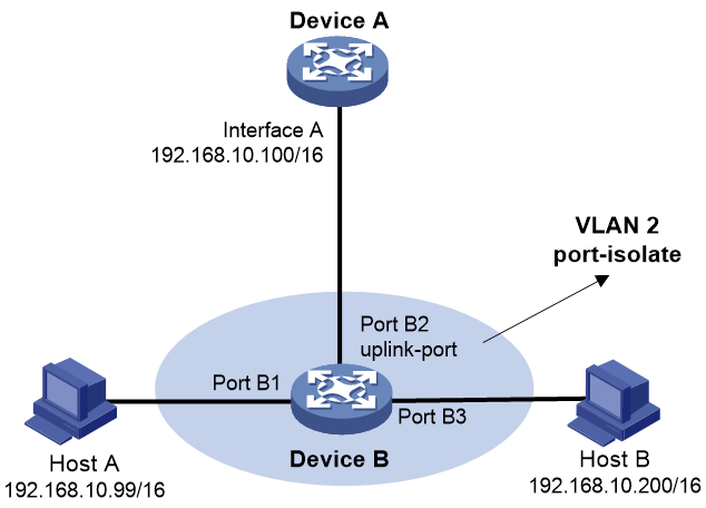
Because Host A's IP address is on the same subnet as Host B's, Host A broadcasts an ARP request for Host B's MAC address. However, Host B cannot receive the ARP request because Host A and Host B are connected to different Device B's ports that are assigned to the same isolation group.
To solve this problem, enable local ARP proxy on Interface A of Device A. The communication process is as follows:
1. Upon receiving the ARP request from Host A, Device A responds with its own MAC address.
2. Based on the reply, Host A uses Device A's MAC address to encapsulate the packet destined for Host B.
3. When receiving the packet, Device A searches for the ARP entry of Host B.
¡ If the ARP entry exists, it forwards the packet to Host B.
¡ If the ARP entry does not exist, the device broadcasts an ARP request to request the MAC address of Host B. After obtaining the MAC address of Host B, the device forwards the packet to Host B.
Restrictions and guidelines
You can enable local proxy ARP to implement Layer 3 intercommunication in the following scenarios:
· Hosts connect to different ports that are assigned to the same VLAN and isolation group.
· Hosts connect to different ports that belong to different sub-VLANs associated with a super VLAN.
Procedure
1. Enter system view.
system-view
2. Enter interface view.
interface interface-type interface-number
3. Enable local proxy ARP.
local-proxy-arp enable [ ip-range start-ip-address to end-ip-address ]
By default, local proxy ARP is disabled.
Enabling inter-VLAN proxy ARP
About this task
As shown in Figure 7, Host A belongs to VLAN 2 and Host B belongs to VLAN 3. Host A and Host B connect to Device B. The uplink port of Device B connects to Device A's Interface A.1, which is configured with VLAN termination.
Figure 7 Application scenario of inter-VLAN proxy ARP
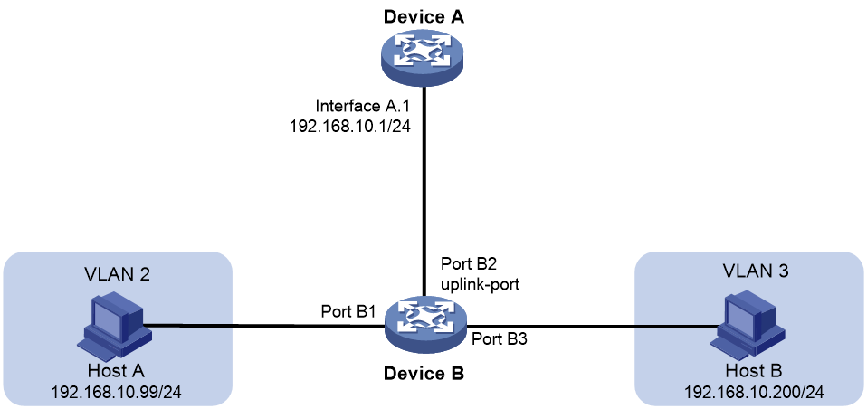
Because Host A's IP address is on the same subnet as Host B's, Host A broadcasts an ARP request for Host B's MAC address. However, Host B cannot receive the ARP request because Host A and Host B belong to different VLANs.
To solve this problem, enable inter-VLAN proxy ARP on Interface A.1 of Device A. The communication process is as follows:
1. Upon receiving the ARP request from Host A, Device A searches for the ARP entry of Host B.
2. If the ARP entry does not exist, Device A broadcasts an ARP request for Host B's MAC address in all VLANs of which the packets are terminated on Interface A.1. After obtaining the MAC address of Host B, Device A determines whether Host A and Host B are in the same VLAN.
¡ If they are in the same VLAN, Device A does not respond to the ARP request from Host A.
¡ If they are in different VLANs, Device A responds to the ARP request from Host A with Host B's MAC address. When Host A sends packets to Host B, Device A forwards the packets to Host B.
Procedure
1. Enter system view.
system-view
2. Enter subinterface view.
interface interface-type interface-number.subnumber
3. Enable inter-VLAN proxy ARP.
proxy-arp enable
By default, inter-VLAN proxy ARP is disabled.
Display and maintenance commands for proxy ARP
Execute display commands in any view.
|
Task |
Command |
|
Display common proxy ARP status. |
display proxy-arp [ interface interface-type interface-number ] |
|
Display local proxy ARP status. |
display local-proxy-arp [ interface interface-type interface-number ] |
Proxy ARP configuration examples
Example: Configuring common proxy ARP
Network configuration
As shown in Figure 8, Host A and Host D have the same prefix and mask, but they are located on different subnets. No default gateway is configured on Host A and Host D.
Configure common proxy ARP on the router to ensure communication between Host A and Host D.

Procedure
|
|
IMPORTANT: · By default, interfaces on the device are disabled (in ADM or Administratively Down state). To have an interface operate, you must use the undo shutdown command to enable that interface. · Physical interfaces in this example must operate in Layer 2 mode. By default, physical interfaces on the device operate in Layer 3 mode. To change the operation mode for physical interfaces, you must use the port link-mode command in interface view. |
# Configure the IP address of HundredGigE 1/0/2.
<Router> system-view
[Router] interface hundredgige 1/0/2
[Router-HundredGigE1/0/2] ip address 192.168.10.99 255.255.255.0
# Enable common proxy ARP on HundredGigE 1/0/2.
[Router-HundredGigE1/0/2] proxy-arp enable
[Router-HundredGigE1/0/2] quit
# Configure the IP address of HundredGigE 1/0/1.
[Router] interface hundredgige 1/0/1
[Router-HundredGigE1/0/1] ip address 192.168.20.99 255.255.255.0
# Enable common proxy ARP on HundredGigE 1/0/1.
[Router-HundredGigE1/0/1] proxy-arp enable
[Router-HundredGigE1/0/1] quit
Verifying the configuration
# Verify that Host A and Host D can ping each other.
Configuring ARP snooping
About ARP snooping
ARP snooping is used in Layer 2 switching networks. It creates ARP snooping entries by using information in ARP packets. ARP fast-reply can use the ARP snooping entries.
Creation of ARP snooping entries
If you enable ARP snooping for a VLAN, ARP packets received in the VLAN are redirected to the CPU. The CPU uses the sender IP and MAC addresses of the ARP packets, and receiving VLAN and port to create ARP snooping entries.
Aging of ARP snooping entries
The aging timer and valid period of an ARP snooping entry are 25 minutes and 15 minutes. If an ARP snooping entry is not updated in 12 minutes, the device sends an ARP request. The ARP request uses the IP address of the entry as the target IP address. If an ARP snooping entry is not updated in 15 minutes, it becomes invalid and cannot be used. After that, if an ARP packet matching the entry is received, the entry becomes valid, and its aging timer restarts.
If the aging timer of an ARP snooping entry expires, the entry is removed.
Protection for ARP snooping
An attack occurs if an ARP packet has the same sender IP address as a valid ARP snooping entry but a different sender MAC address. The ARP snooping entry becomes invalid, and it is removed in 1 minute.
Enabling ARP snooping
1. Enter system view.
system-view
2. Enter VLAN view.
vlan vlan-id
3. Enable ARP snooping
arp snooping enable
By default, ARP snooping is disabled.
Display and maintenance commands for ARP snooping
Execute display commands in any view and reset commands in user view.
|
Task |
Command |
|
Display ARP snooping entries. |
display arp snooping [ vlan vlan-id ] [ slot slot-number ] [ count ] display arp snooping ip ip-address [ slot slot-number ] |
|
Clear ARP snooping entries. |
reset arp snooping [ ip ip-address | vlan vlan-id ] |
Configuring ARP fast-reply
About ARP fast-reply
ARP fast-reply enables a device to directly answer ARP requests according to IP source guard entries or ARP snooping entries. ARP fast-reply functions in a VLAN. For information about IP source guard, see IP source guard configuration in Security Configuration Guide.
If the target IP address of a received ARP request is the IP address of the VLAN interface, the device delivers the request to the ARP module. If not, the device takes the following steps to process the packet:
1. Search the IP source guard binding entry table for a match by using the target IP address.
2. If a match is found, whether the device returns a reply depends on the type of interface in the matching entry.
¡ If the interface is the Ethernet interface that received the ARP request, the device does not return any reply.
¡ If the interface is an Ethernet interface other than the receiving interface, the device returns a reply according to the matching entry.
3. If no matching IP source guard entry is found and ARP snooping is enabled, the device searches the ARP snooping table.
¡ If the interface in the matching entry is the Ethernet interface that received the ARP request, the device does not return any reply.
¡ If the interface is an Ethernet interface other than the receiving interface, the device returns a reply according to the ARP snooping entry.
4. If no match is found in both tables, the ARP request is forwarded to other interfaces except the receiving interface in the VLAN, or delivered to other modules.
Enabling ARP fast-reply
Restrictions and guidelines
To improve the availability of ARP fast-reply, enable ARP snooping at the same time.
Procedure
1. Enter system view.
system-view
2. Enter VLAN view.
vlan vlan-id
3. Enable ARP fast-reply.
arp fast-reply enable
By default, ARP fast-reply is disabled.
ARP fast-reply configuration examples
Example: Configuring ARP fast-reply
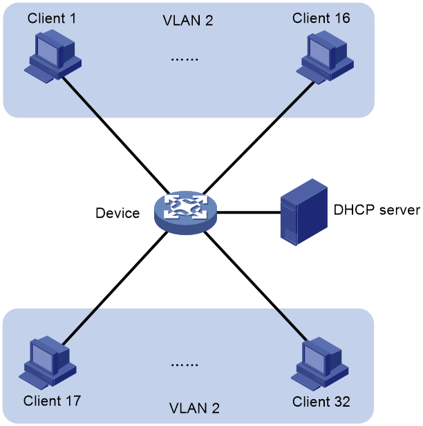
Network configuration
As shown in Figure 9, all clients are in VLAN 2, and access the network through the device. They have obtained IP addresses through DHCP.
Enable ARP snooping and ARP fast-reply for VLAN 2. The device directly returns an ARP reply without broadcasting received ARP requests in the VLAN.
Procedure
|
|
IMPORTANT: By default, interfaces on the device are disabled (in ADM or Administratively Down state). To have an interface operate, you must use the undo shutdown command to enable that interface. |
# Enable ARP snooping for VLAN 2 on the device.
<Device> system-view
[Device] vlan 2
[Device-vlan2] arp snooping enable
# Enable ARP fast-reply for VLAN 2 on the device.
[Device-vlan2] arp fast-reply enable
[Device-vlan2] quit
Configuring ARP suppression
About ARP suppression
The ARP suppression feature enables a device to directly answer ARP requests by using ARP suppression entries. The device generates ARP suppression entries based on dynamic ARP entries. This feature is typically configured on the PEs or VTEPs connected to base stations in an MPLS L2VPN, VPLS, VXLAN, and EVPN networks.
You can also configure the ARP suppression push feature to push ARP suppression entries by broadcasting gratuitous ARP packets.
Enabling ARP suppression for a cross-connect group
1. Enter system view.
system-view
2. (Optional.) Enable the ARP suppression push feature and set a push interval.
arp suppression push interval interval
By default, the ARP suppression push feature is disabled.
3. Create a cross-connect group and enter its view.
xconnect-group group-name
For more information about this command, see the MPLS L2VPN commands in MPLS Command Reference.
4. Create a cross-connect and enter its view.
connection connection-name
For more information about this command, see the MPLS L2VPN commands in MPLS Command Reference.
5. Enable ARP suppression.
arp suppression enable
By default, ARP suppression is disabled.
Enabling ARP suppression for a VSI
1. Enter system view.
system-view
2. (Optional.) Enable the ARP suppression push feature and set a push interval.
arp suppression push interval interval
By default, the ARP suppression push feature is disabled.
3. Enter VSI view.
vsi vsi-name
4. Enable ARP suppression.
arp suppression enable
By default, ARP suppression is disabled.
Display and maintenance commands for ARP suppression
Execute display commands in any view and reset commands in user view.
|
Task |
Command |
|
Display ARP suppression entries. |
display arp suppression xconnect-group [ name group-name ] [ slot slot-number ] [ count ] |
|
Clear ARP suppression entries. |
reset arp suppression xconnect-group [ name group-name ] |
ARP suppression configuration examples
Example: Configuring ARP suppression
Network configuration
As shown in Figure 10, the base station, Router A, and Router B are in an MPLS L2VPN.
Enable ARP suppression on Router A to directly reply to ARP requests for Router B.

Procedure
|
|
IMPORTANT: By default, interfaces on the device are disabled (in ADM or Administratively Down state). To have an interface operate, you must use the undo shutdown command to enable that interface. |
1. Configure IP addresses for the interfaces, and make sure the base station can reach the L3VE interface VE-L3VPN 1 of Router B. (Details not shown.)
2. Configure ARP suppression on Router A:
# Create a cross-connect group named vpna and create a cross-connect named svc in the group.
<RouterA> system-view
[RouterA] xconnect-group vpna
[RouterA-xcg-vpna] connection svc
# Enable ARP suppression for cross-connect svc in cross-connect group vpna.
[RouterA-xcg-vpna-svc] arp suppression enable
Verifying the configuration
1. On the base station, clear ARP entries, and ping the L3VE interface VE-L3VPN 1 of Router B. (Details not shown.)
2. Verify that Router A has ARP suppression entries for the base station and Router B.
[RouterA-xcg-vpna-svc] display arp suppression xconnect-group
IP address MAC address Xconnect-group Connection Aging
10.1.1.1 00e0-fc04-582c vpna svc 25
10.1.1.3 0023-89b7-0861 vpna svc 25
3. Enable ARP debugging on Router B to verify that Router B does not receive an ARP request from the base station under the following conditions (details not shown):
a. Clear ARP entries on the base station.
b. Ping the L3VE interface VE-L3VPN 1 of Router B from the base station.
Configuring ARP direct route advertisement
About ARP direct route advertisement
Mechanism of ARP direct route advertisement
The ARP direct route advertisement feature advertises host routes instead of advertising the network route.
Application in Layer 3 access networks
As shown in Figure 11, ARP direct route advertisement is enabled on Interface A and Interface B. This feature generates a host route to Server A and a host route to Server B for the routing protocols to advertise. So each device forwards only the traffic destined to the server within the network, which saves bandwidth.
Figure 11 Application in a Layer 3 access network

If you enable ARP direct route advertisement on the public network or in a VPN instance, all interfaces on the public network or in the VPN instance are enabled with ARP direct route advertisement.
Enabling ARP direct route advertisement
1. Enter system view.
system-view
2. Enter interface view.
interface interface-type interface-number
3. Enable ARP direct route advertisement.
¡ Enable ARP direct route advertisement in system view.
arp route-direct advertise
¡ Execute the following commands in sequence to enable ARP direct route advertisement on an interface:
interface interface-type interface-number
arp route-direct advertise
¡ Execute the following commands in sequence to enable ARP direct route advertisement in a VPN instance:
ip vpn-instance vpn-instance-name
arp route-direct advertise
By default, the ARP direct route advertisement feature is disabled.