- Table of Contents
- Related Documents
-
| Title | Size | Download |
|---|---|---|
| 01-Text | 14.43 MB |
Contents
General safety recommendations
Examining the installation site
Installation tools and accessories
Mounting the router on a workbench
Installing the router in a 19-inch rack
Connecting the grounding cable
Installing an interface module
Connecting the router to the network
Starting and configuring the router
Connecting the console cable and setting terminal parameters
Accessing the router for the first time
Replacing an MPU from an MSR5620
Replacing an MPU from an MSR 56-60/80 router
Replacing an external Micro SD card
No display on the configuration terminal
Garbled characters on the configuration terminal
No response from the serial port
Interface module, cable, and connection failure
System failure during operation
1 Preparing for installation
The MSR5600 router series includes the models in Table1-1.
Table1-1 MSR5600 router series models
|
Model (marked on the front panel) |
Product code |
|
MSR5620 |
RT-MSR5620 |
|
MSR 56-60 |
RT-MSR5660 |
|
MSR 56-80 |
RT-MSR5680 |
Safety recommendations
Safety symbols
When reading this document, note the following symbols:
![]() WARNING means an alert that calls attention to important information that if
not understood or followed can result in personal injury.
WARNING means an alert that calls attention to important information that if
not understood or followed can result in personal injury.
![]() CAUTION means an alert that calls attention to important information that if
not understood or followed can result in data loss, data corruption, or damage
to hardware or software.
CAUTION means an alert that calls attention to important information that if
not understood or followed can result in data loss, data corruption, or damage
to hardware or software.
General safety recommendations
· Keep the chassis and installation tools away from walk areas.
· Make sure the ground is dry and flat and anti-slip measures are in place.
· Unplug all the external cables (including power cords) before moving the chassis.
Electricity safety
· Locate the emergency power-off switch in the room before installation. Shut the power off at once in case accident occurs. Disconnect the power cord of the router if necessary.
· Make sure the router is correctly grounded.
· Do not open or close the chassis cover when the router is powered on.
· Correctly connect the interface cables of the router.
· Use an uninterrupted power supply (UPS).
· If there are two power inputs, disconnect the two power inputs to power off the router.
· Do not work alone when the router has power.
· Always make sure the power has been disconnected during the installation and replacement procedures.
Laser safety
|
|
WARNING! Do not stare into any open apertures of operating transceiver modules or optical fiber connectors. The laser light emitted from these apertures might hurt your eyes. |
|
|
CAUTION: · Before you remove the optical fiber connector from a fiber port, execute the shutdown command in interface view to shut down the port. · Insert a dust cap into any unused optical fiber connector and a dust plug into any unused fiber port or transceiver module port to protect them from contamination and ESD damage. |
Examining the installation site
The routers can only be used indoors. To make sure the router operates correctly and to prolong its service lifetime, the installation site must meet the following requirements.
Temperature and humidity
Maintain temperature and humidity in the equipment room as described in Table1-2.
· Lasting high relative humidity can cause poor insulation, electricity leakage, mechanical property change of materials, and metal corrosion.
· Lasting low relative humidity can cause washer contraction and ESD and bring problems including loose captive screws and circuit failure.
· High temperature can accelerate the aging of insulation materials and significantly lower the reliability and lifespan of the router.
Table1-2 Temperature and humidity requirements
|
Operating temperature |
Operating humidity |
|
0°C to 45°C (32°F to 113°F) |
5% RH to 95% RH, noncondensing |
Cleanliness
Dust buildup on the chassis might result in electrostatic adsorption, which causes poor contact of metal components and contact points, especially when indoor relative humidity is low. In the worst case, electrostatic adsorption can cause communication failure. To ensure correct operation, the equipment room must meet the dust concentration requirements listed in Table1-3.
Table1-3 Dust concentration limit in the equipment room
|
Substance |
Concentration limit (particles/m3) |
|
Dust particles |
≤ 3 x 10⁴ (No visible dust on desk in three days) |
|
NOTE: Dust particle diameter ≥ 5 µm |
|
The equipment room must also meet strict limits on salts, acids, and sulfides to eliminate corrosion and premature aging of components, as shown in Table1-4.
Table1-4 Harmful gas limits in the equipment room
|
Gas |
Max. (mg/m3) |
|
SO2 |
0.2 |
|
H2S |
0.006 |
|
NH3 |
0.05 |
|
Cl2 |
0.01 |
|
NO2 |
0.04 |
Cooling system
The router uses left to rear airflow for heat dissipation.
Figure1-1 Airflow through the MSR 5600 chassis
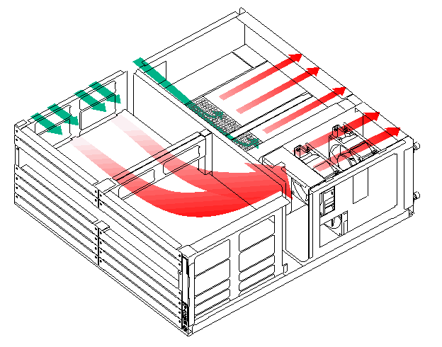
To ensure good ventilation, the following requirements must be met:
· Leave a minimum clearance of 10 cm (3.94 in) for the air inlet and outlet vents.
· The installation site has a good cooling system.
ESD prevention
|
|
CAUTION: Check the resistance of the ESD wrist strap for safety. The resistance reading should be in the range of 1 to 10 megohm (Mohm) between human body and the ground. |
To prevent electrostatic discharge (ESD), follow these guidelines:
· Make sure the router and the floor are reliably grounded.
· Take dust-proof measures for the equipment room.
· Maintain the humidity and temperature at acceptable levels.
· Always wear an ESD wrist strap and ESD cloth when touching a circuit board or transceiver module.
The router does not supply an ESD wrist wrap. Prepare an ESD wrist wrap yourself.
· Place the removed CF card or interface module on an antistatic workbench, with the face upward, or put it into an antistatic bag.
· Touch only the edges, instead of electronic components when you observe or move a removed CF card or interface module.
To attach an ESD wrist strap:
1. Wear the wrist strap on your wrist.
2. Lock the wrist strap tight around your wrist to keep good contact with the skin.
3. Insert the ESD plug into the ESD socket.
4. Connect the alligator clip to the rack.
EMI
All electromagnetic interference (EMI) sources, from outside or inside of the router and application system, adversely affect the router in the following ways:
· A conduction pattern of capacitance coupling.
· Inductance coupling.
· Electromagnetic wave radiation.
· Common impedance (including the grounding system) coupling.
To prevent EMI, perform the following tasks:
· If AC power is used, use a single-phase three-wire power receptacle with protection earth (PE) to filter interference from the power grid.
· Keep the router far away from radio transmitting stations, radar stations, and high-frequency devices to make sure the EMI levels do not exceed the compliant range.
· Use electromagnetic shielding, for example, shielded interface cables, when necessary.
· To prevent signal ports from getting damaged by overvoltage or overcurrent caused by lightning strikes, only route interface cables indoors. If you must route interface cables outdoors, install network port lightning protectors.
Lightning protection
The router has its own lightning protection system. To better protect the router from lightning, do as follows:
· Make sure the grounding cable of the chassis is reliably grounded.
· Make sure the grounding terminal of the AC power receptacle is reliably grounded.
· Install a lightning arrester at the input end of the power supply to enhance the lightning protection capability of the power supply.
· Install a special lightning arrester at the input end of outdoor signal lines (for example, E1/T1 line) to which interface modules of the router are connected to enhance the lightning protection capability.
Rack-mounting
Before mounting the router in a standard 19-inch rack, adhere to the following requirements:
· The rack is equipped with a good ventilation system.
· The rack is sturdy enough to support the router and its accessories.
· For heat dissipation and device maintenance, make sure the front and rear of the rack are at least 0.8 m (2.62 ft) away from walls or other devices, and the headroom in the equipment room is no less than 3 m (9.84 ft).
Installation tools and accessories
Figure1-2 Installation tools
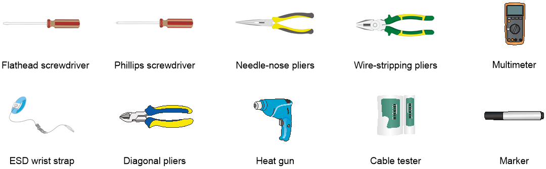
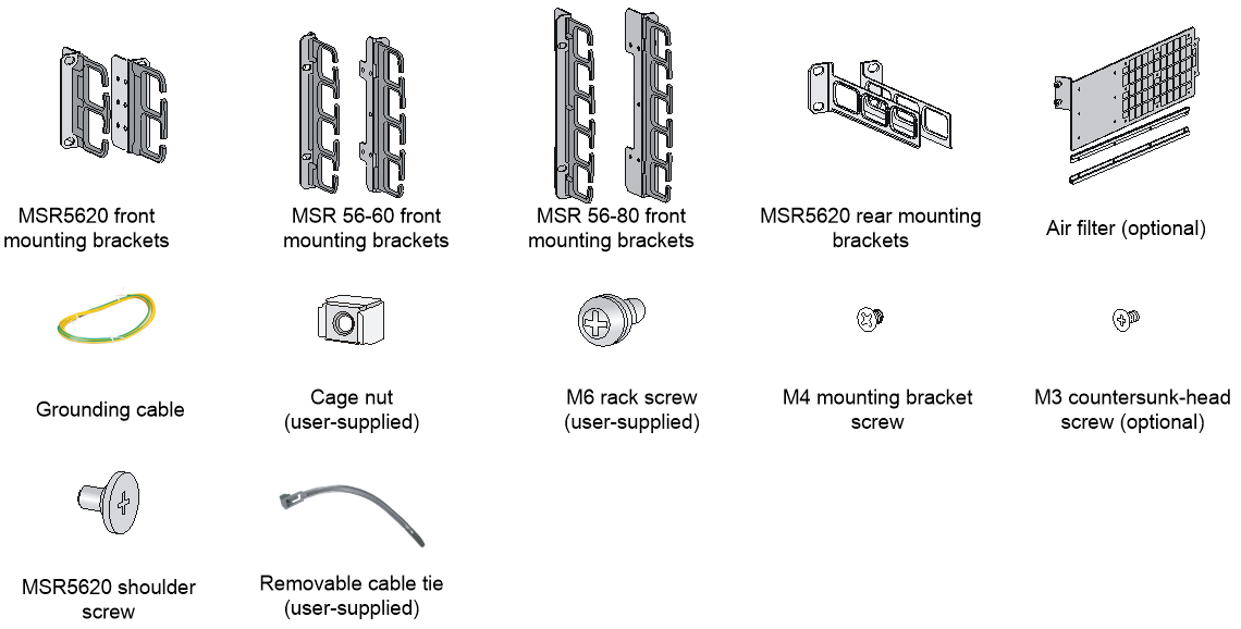
Figure1-3 Installation accessories
Pre-installation checklist
Table1-5 Pre-installation checklist
|
Item |
Requirements |
Result |
|
|
Installation site |
Ventilation |
· There is a minimum clearance of 10 cm (3.94 in) around the inlet and outlet vents for heat dissipation of the router chassis. · A good ventilation system is available at the installation site. |
|
|
Operating temperature |
0°C to 45°C (32°F to 113°F). |
|
|
|
Operating humidity |
5% RH to 95% RH, noncondensing. |
|
|
|
Cleanliness |
· Dust concentration ≤ 3 × 10⁴ particles/m3. · No visible dust on desk within three days. |
|
|
|
ESD prevention |
· The equipment and floor are reliably grounded. · The equipment room is dust-proof. · The humidity and temperature are at acceptable levels. · Wear an ESD wrist strap or ESD gloves and ESD clothing when touching a circuit board. · Place the removed CF card or interface module on an antistatic workbench, with the face upward, or put it into an antistatic bag. · Touch only the edges, instead of electronic components when observing or moving a removed CF card or interface module. |
|
|
|
EMI prevention |
· Effective measures are taken for filtering interference from the power grid. · The protection ground of the router is away from the grounding facility of power equipment or lightning protection grounding facility. · The router is far away from radio transmitting stations, radar stations, and high-frequency devices. · Electromagnetic shielding, for example, shielded interface cables, is used as required. |
|
|
|
Lightning protection |
· The device is reliably grounded. · The AC power source is reliably grounded. · (Optional.) Network port lightning protectors are available. · (Optional.) A surge protected power strip is available. |
|
|
|
Electricity safety |
· A UPS is available. · The power-off switch in the equipment room is identified and accessible so that the power can be immediately shut off when an accident occurs. |
|
|
|
Workbench |
· The workbench is stable enough. · The workbench is reliably grounded. |
|
|
|
Rack-mounting requirements |
· The rack has a good ventilation system. · The rack is sturdy enough to support the weight of the router and installation accessories. · The size of the rack is appropriate for the router. · The front and rear of the rack are a minimum of 0.8 m (2.62 ft) away from walls or other devices. |
|
|
|
Safety precautions |
· The router is far away from any moist area and heat source. · The emergency power switch in the equipment room is located. |
|
|
|
Tools |
· Installation accessories supplied with the router are available. · User supplied tools are available. |
|
|
|
Reference |
· Documents shipped with the router are available. · Online documents are available. |
|
|
2 Installing the router
|
WARNING! To avoid injury, do not touch bare wires, terminals, or parts with high-voltage hazard signs. |
|
|
IMPORTANT: · The barcode on the router chassis contains product information that must be provided to local sales agent before you return a faulty router for service. · Keep the tamper-proof seal on a mounting screw on the chassis cover intact, and if you want to open the chassis, contact H3C for permission. Otherwise, H3C shall not be liable for any consequence. |
Installation prerequisites
· You have read "Preparing for installation" carefully.
· All requirements in "Preparing for installation" are met.
Installation flow
You can install the router on a workbench or on a rack. Select an installation method according to the installation environment, and follow the installation flowchart shown in Figure2-1.

Installing the router
Installing an air filter
No air filter is provided with the router. Purchase one yourself.
If the router is installed with an air filter, rear mounting brackets cannot be installed. A rack shelf is required to mount the router installed with an air filter to the rack.
1. Face the left side (side of the inlet vents) of the router.
2. Install the upper and lower guide rails of the air filter to the chassis. See Figure2-2.
3. Fasten the fastening screws on the guide rails with a Phillips screwdriver.
Figure2-2 Installing the upper and lower guide rails

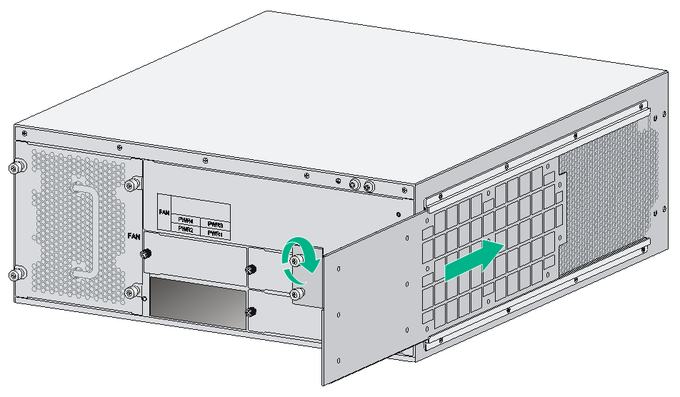
4. Push the air filter along the slide rails from the rear side of the chassis to the front.
5. Fasten the captive screws on the air filter.
Figure2-3 Pushing the air filter along the guide rails
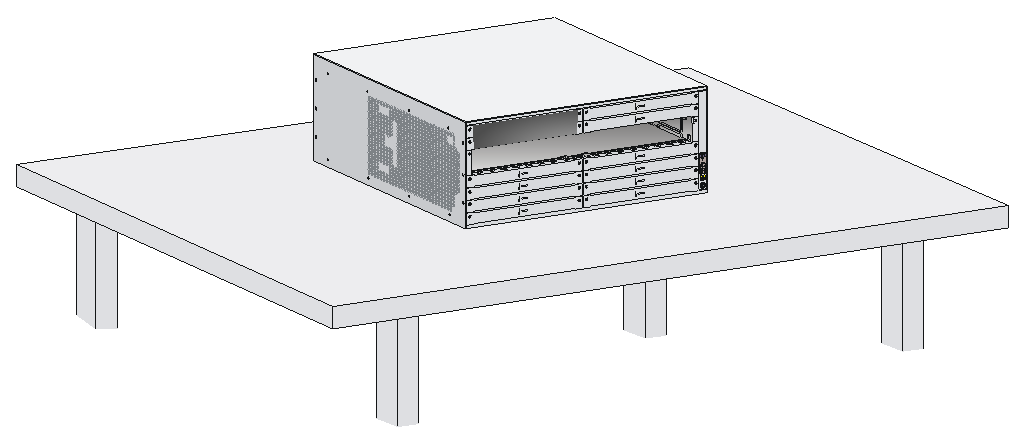
Mounting the router on a workbench
|
|
IMPORTANT: · Ensure good ventilation and 10 cm (3.94 in) of clearance around the chassis for heat dissipation. · Avoid placing heavy objects on the router. |
To mount the router on a workbench:
1. Make sure the workbench is clean, stable, and reliably grounded.
2. Place the router on the workbench with the upside up.
Figure2-4 Mounting the router on a workbench
Installing the router in a 19-inch rack
Mounting brackets
The mounting brackets vary with router models, as shown in Figure2-5 through Figure2-8.
Figure2-5 MSR5620 front mounting brackets
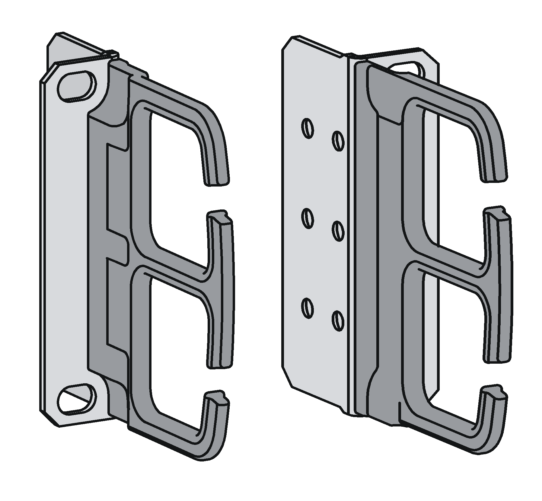
Figure2-6 MSR 56-60 front mounting brackets
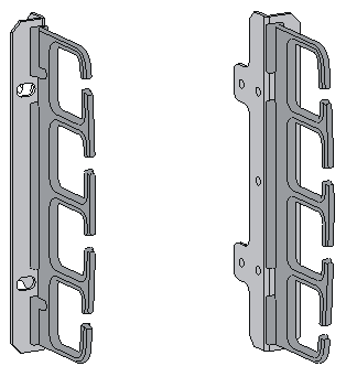
Figure2-7 MSR 56-80 front mounting brackets
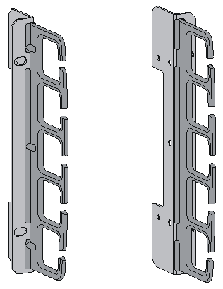
Figure2-8 MSR5620 rear mounting brackets

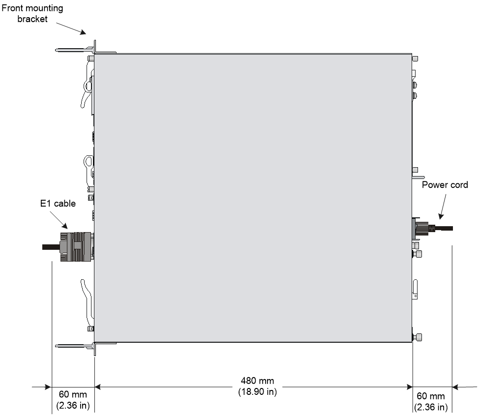
Router dimensions
Figure2-9 Router dimensions
To house the router, the rack must meet the requirements described in Table2-1.
Table2-1 Router dimensions and requirements for the rack
|
Router model |
Dimensions |
Requirements for the rack |
|
MSR5620 |
· Height—88.1 mm (3.47 in), 2 RU · Width—440 mm (17.32 in) · Total depth—600 mm (23.62 in) ¡ Chassis depth—480 mm (18.90 in) ¡ E1 cable-connecting depth—60 mm (2.36 in) ¡ AC/DC power cord-connecting depth—60 mm (2.36 in) |
· Depth—A minimum of 0.68 m (2.23 ft) · Distance from the front post to the front door—A minimum of 80 mm (3.15 in) · Distance from the front post to the rear door—A minimum of 550 mm (21.65 in) · Distance from the front post to the rear post ¡ 310 mm (12.20 in) to 440 mm (17.32 in) ¡ 465 mm (18.31 in) to 595 mm (23.43 in) · As a best practice, use a rack shelf to mount the router in a rack. |
|
MSR 56-60 |
· Height—175.1 mm (6.89 in), 4 RU · Width—440 mm (17.32 in) · Total depth—600 mm (23.62 in) ¡ Chassis depth—480 mm (18.90 in) ¡ E1 cable-connecting depth—60 mm (2.36 in) ¡ AC/DC power cord-connecting depth—60 mm (2.36 in) |
· Depth—A minimum of 0.68 m (2.23 ft) · Distance from the front post to the front door—A minimum of 80 mm (3.15 in) ¡ Distance from the front post to the rear door—A minimum of 550 mm (21.65 in) · The router is not provided with rear mounting brackets. As a best practice, use a rack shelf to mount the router in a rack. |
|
MSR 56-80 |
· Height—219.5 mm (8.64 in), 5 RU · Width—440 mm (17.32 in) · Total depth—600 mm (23.62 in) ¡ Chassis depth—480 mm (18.90 in) ¡ E1 cable-connecting depth—60 mm (2.36 in) ¡ AC/DC power cord-connecting depth—60 mm (2.36 in) |
· Depth—A minimum of 0.68 m (2.23 ft) · Distance from the front post to the front door—A minimum of 80 mm (3.15 in) · Distance from the front post to the rear door—A minimum of 550 mm (21.65 in) · The router is not provided with rear mounting brackets. As a best practice, use a rack shelf to mount the router in a rack. |
Mounting the router in the rack
|
|
CAUTION: The mounting brackets and rack shelf can support only the weight of the router. To avoid device damage, do not place any object on the router. |
MSR5620 routers are provided with rear mounting brackets. They support rack mounting by using rear mounting brackets or and rack shelves. MSR 56-60 and MSR 56-80 routers support only rack mounting by using rack shelves.
To install a router in a rack by using rear mounting brackets:
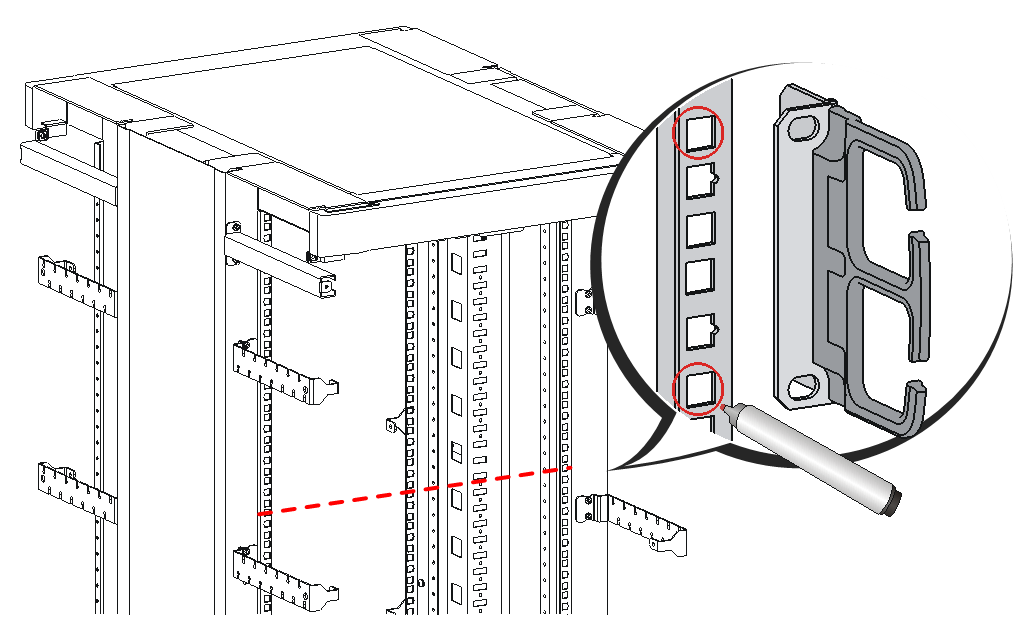
1. Use a front mounting bracket to mark the positions of cage nuts on the front rack posts, making sure they are at the same level.
Figure2-10 Marking the positions of cage nuts for the front mounting brackets
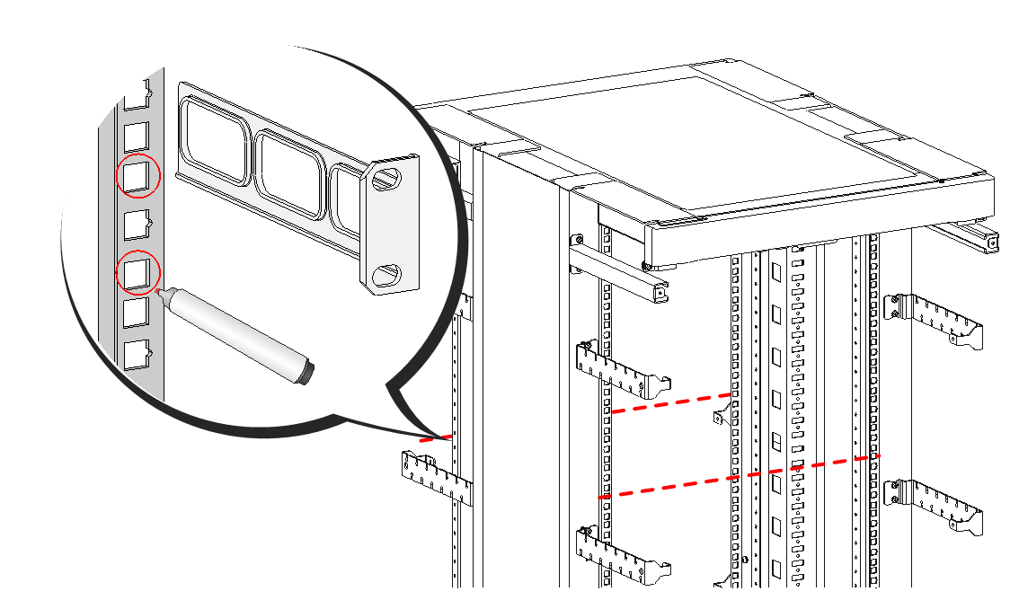
2. Use a rear mounting bracket to mark the positions of cage nuts on the rear rack posts, making sure the front and rear mounting brackets are at the same level.
Figure2-11 Marking the positions of cage nuts for the rear mounting brackets
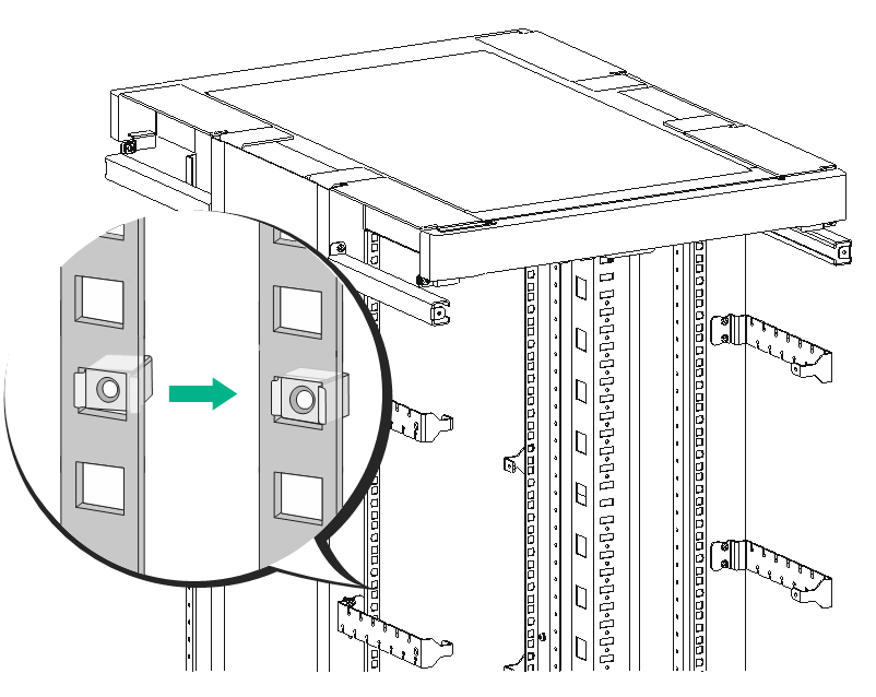
3. Insert one edge of a cage nut into the square hole on a rack post. Use a flat-blade screwdriver to compress the other edge of the cage nut, and then push the cage nut fully into the hole.
4. Repeat step 3 to install other cage nuts to all the marked positions on the rack posts.
Figure2-12 Installing cage nuts

5. Attach the rear mounting brackets to the rack and fasten the screws.
The depth of the router might be greater or smaller than the depth of the rack, depending on the rack model. If the depth of the router is greater than the depth of the rack, follow Figure2-13 to attach the rear mounting brackets. If smaller, follow Figure2-14 to attach the rear mounting brackets.
Figure2-13 Attaching the rear mounting brackets (router depth greater than rack depth)

Figure2-14 Attaching the rear mounting brackets (router depth smaller than rack depth)

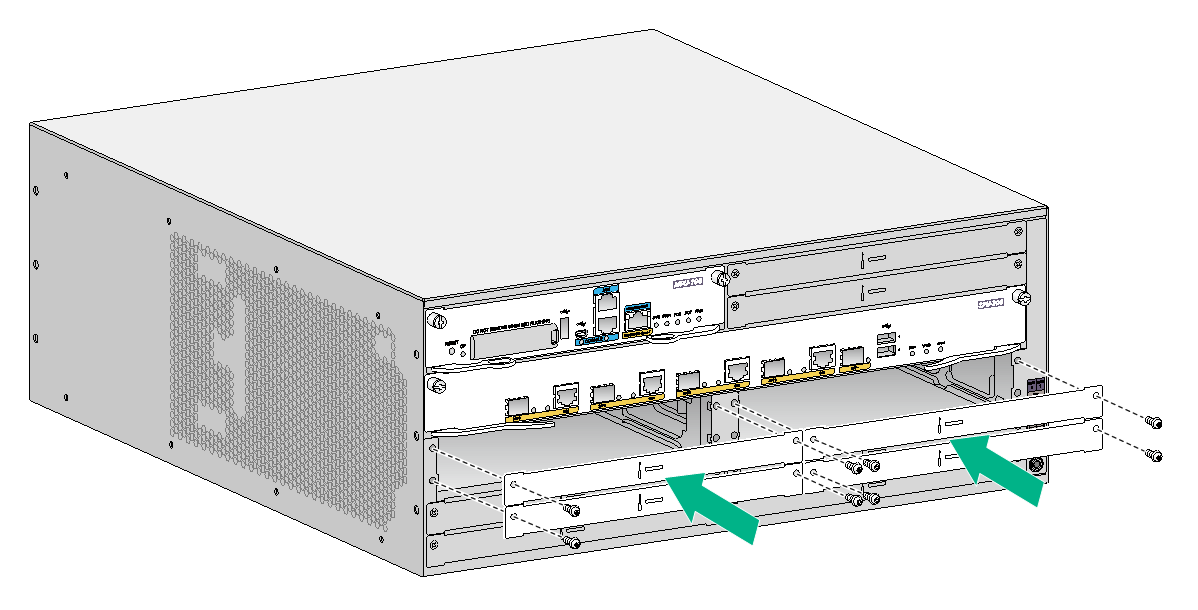
6. Attach the front mounting brackets to the chassis and fasten the screws.
7. Attach load-bearing screws to the rear of the chassis.
Figure2-15 Attaching the front mounting brackets and load-bearing screws to the MSR5620

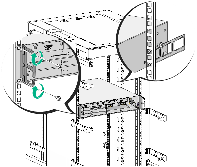
8. Place the router on the rack, making sure the load-bearing screws hang on the rear mounting brackets. Secure the chassis in the rack by attaching the front mounting brackets with pan head screws onto the back.
Figure2-16 Mounting the router in the rack
To install a router in the rack by using the rack shelf:
9. Use a front mounting bracket to mark the positions of cage nuts, making sure they are at the same level.
10. Insert one edge of a cage nut into the hole. Use a flat-blade screwdriver to compress the other edge of the cage nut, and then push the cage nut fully into the hole.
11. Install other cage nuts to all the marked positions on the rack posts.
Figure2-17 Installing a cage nut
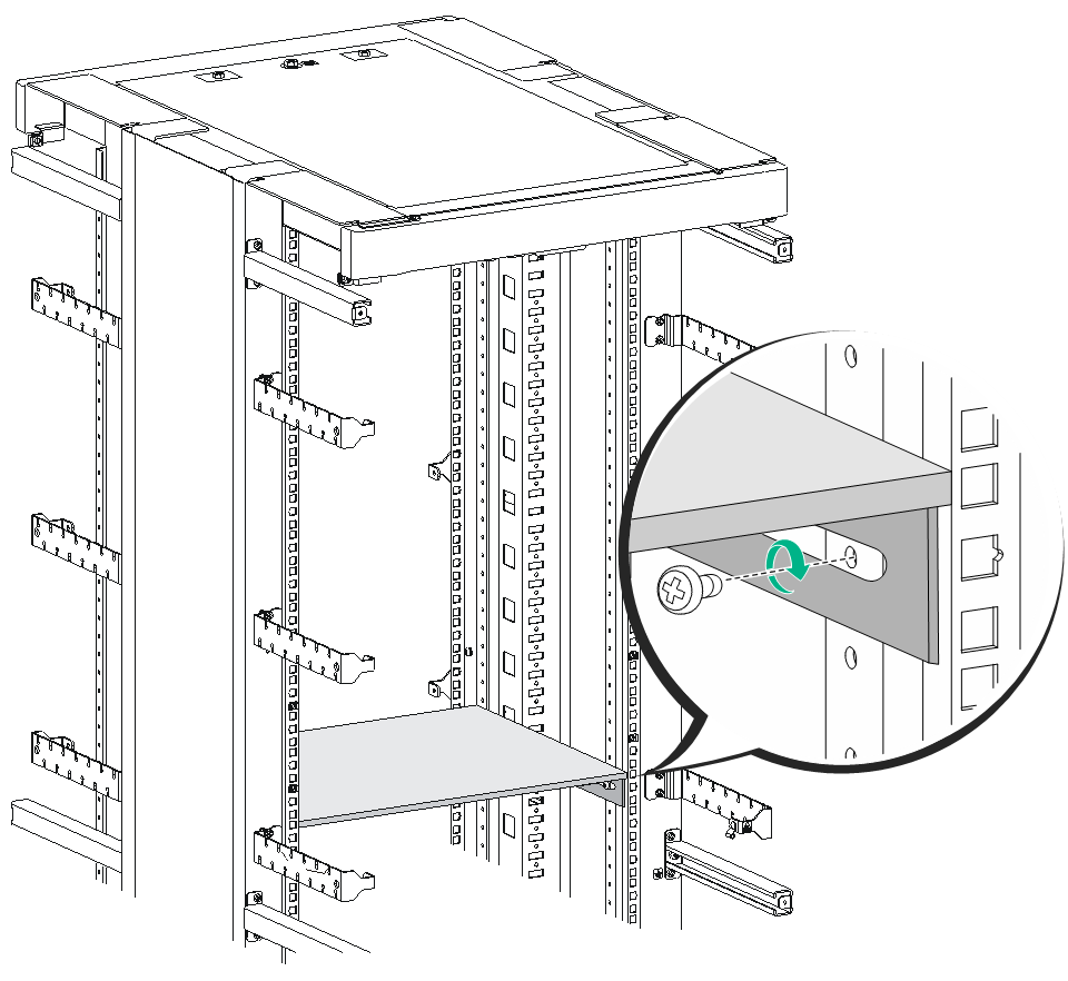
12. Install a rack shelf at the position where the cage nuts are installed.
Figure2-18 Installing a rack shelf
13. Attach the front mounting brackets to the chassis and fasten the screws clockwise.
Figure2-19 Attaching the front mounting brackets to the MSR5620

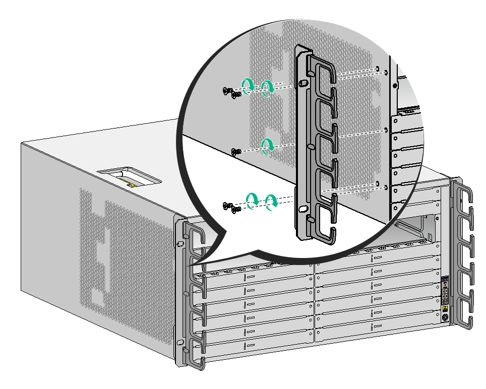
Figure2-20 Attaching the front mounting brackets to the MSR 56-60
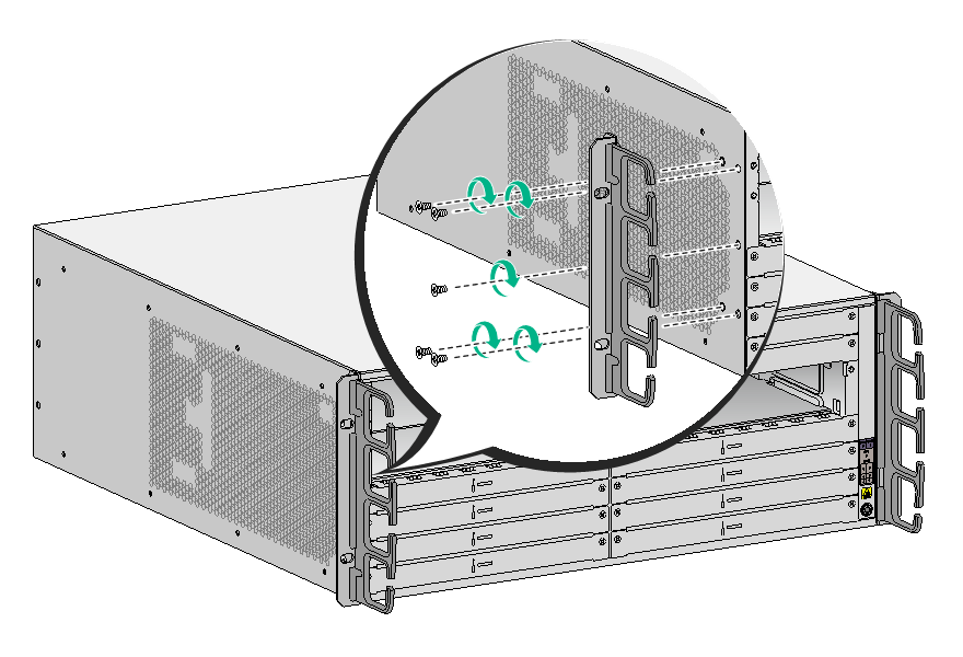
Figure2-21 Attaching the front mounting brackets to the MSR 56-80
14. Place the router on the rack shelf, and secure the chassis by attaching the front mounting brackets with proper pan head screws to the rack.
The specifications of pan head screws must satisfy the installation requirements, and rustproof treatment has been made to their surfaces.
Figure2-22 shows installing an MSR 56-60 router to the rack. Install MSR5620/56-80 routers in the same way.
Figure2-22 Mounting the router in the rack

Connecting the grounding cable
|
|
CAUTION: · Correctly connecting the grounding cable is crucial to lightning protection and EMI protection. To install and use the router, first connect the grounding cable reliably for the router. · Make sure the resistance reading between the chassis and the ground is less than 5 ohms. |
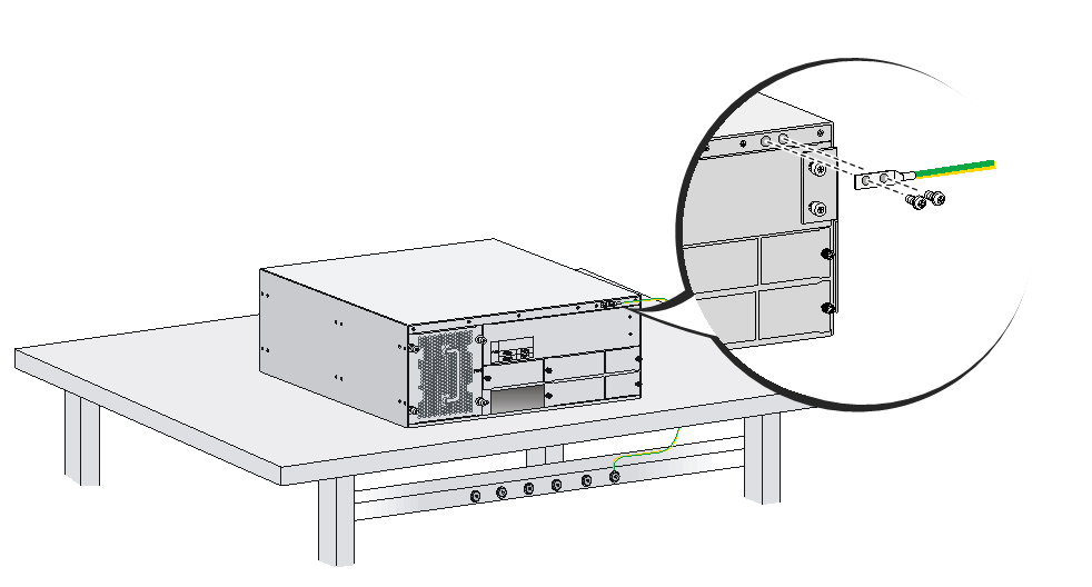
To connect the grounding cable:
1. Use a Phillips screwdriver to remove the grounding screws from the grounding holes in the rear panel of the chassis.
2. Use the grounding screws to attach the grounding lug of the grounding cable to the grounding holes. Use the Phillips screwdriver to fasten the screws.
3. Connect the other end of the grounding cable according to the grounding method you use:
¡ Grounding the device with a grounding strip—Connect the other end of the grounding cable to the grounding strip
Make sure the grounding strip has been reliably grounded.
Figure2-23 Grounding the device with a grounding strip
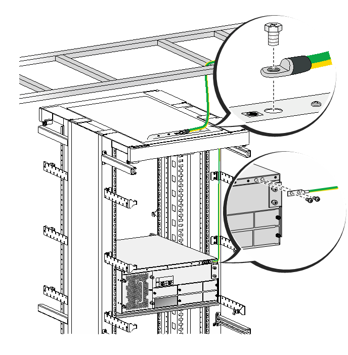
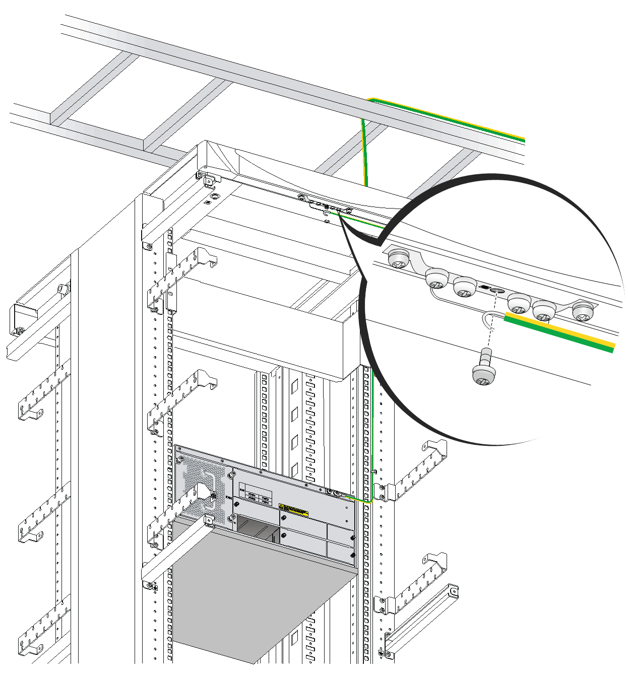
¡ Grounding the device with the rack—Connect the other end of the grounding cable to the grounding terminal on the rack.
Make sure the rack has been reliably grounded.
Figure2-24 Grounding the device with the rack
¡ Grounding the device with a grounding conductor buried in the earth—If earth is available at the installation site, hammer a 0.5 m (1.64 ft) or longer angle iron or steel tube into the earth to serve as a grounding conductor. Weld the yellow-green grounding cable to the angel iron or steel tube and treat the joint for corrosion protection.
Installing an MPU
|
|
CAUTION: · To start the MSR 56-60 or MSR 56-80 router, a minimum of one MPU is required. · The router supports active/standby MPU switchover when you install two MPUs for the router. For the standby MPU to operate correctly, make sure the active and standby MPUs are the same model. · To avoid MPU damage and device failure, do not power off the device while the MPU is booting. · Before you remove an MPU with a storage medium on an operating router, execute the umount command to unmount the file system. Do not remove the MPU until the system displays a message that the file system has been unmounted. · Do not perform any active/standby MPU switchover operations when the system LED on an MPU flashes yellow and green alternatively. |
The MSR5620 router supports only the MPU-60. The MSR 56-60 and MSR 56-80 routers support the MPU-100, MPU-100-X1, and MPU-100-G.
Only the MPU-100-X1 supports an mSATA SSD drive. No SSD drive is provided with the router. Prepare one yourself if required.
Installing an SSD drive
1. Locate the SSD drive slot on the MPU-100-X1 MPU. See Figure2-25.

|
(1) Front panel |
(2) SSD drive slot |
2. Align the golden plating on the SSD drive with the mSATA connector in the slot.
3. Slightly press the SSD drive until it is level with the surface of the connector.
4. Use a Phillips screwdriver to screw the SSD drive into place.
Figure2-26 Installing an SSD drive

Installing the MPU-60
1. Insert the MPU-60 into the MPU slot along the guide rails.
2. Use a Phillips screwdriver to fasten the captive screws to secure the MPU-60 to the router.
Figure2-27 Installing the MPU-60

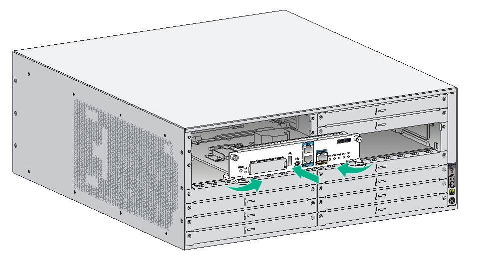
Installing the MPU-100
1. Insert the MPU-100 into the MPU slot along the guide rails, and push the ejector levers inward.
2. Use a Phillips screwdriver to fasten the captive screws to secure the MPU-100 to the router.
Figure2-28 Installing the MPU-100
Installing an SPU and an SPE
|
|
CAUTION: · SPUs are not hot swappable. Make sure the router is powered off before installing an SPU. · SPEs are hot swappable. However, hot-swapping an SPE is not allowed while an MPU-100-X1 is starting up. · Do not perform any active/standby SPE switchover operations when the system LED on an MPU flashes yellow and green alternatively. |
The MSR5620 router has SPUs integrated on it and do not require SPU installation.
The MSR 56-60 and MSR 56-80 routers support the SPU-100, SPU-200, SPU-300, SPU-100-X1, SPU-200-X1, SPU-300-G, SPU-400-X1, and SPU-600-X1. An SPU-600-X1 provides two slots and you can install SPE-S1 and SPE-S3 on an SPU-600-X1.
Installing an SPU-100/200/300/100-X1/200-X1/300-G/400-X1
The SPU-300-G can only be used together with the MPU-100-G.
To install an SPU-100/200/300/100-X1/200-X1/300-G/400-X1:
1. Insert the SPU into the slot along the guide rails, and push the ejector levers inward.
2. Use a Phillips screwdriver to fasten the captive screws to secure the SPU to the router.
Figure2-29 Installing an SPU-100/200/300/100-X1/200-X1/300-G/400-X1
Installing an SPU-600-X1 and an SPE
An SPU-600-X1 can work only when a minimum of one SPE installed on it.
To use an SPU-600-X1 on the router, the router must use only the MPU-100-X1 MPUs and be installed with a minimum of two power supplies.
To install two SPEs on an SPU-600-X1, make sure the SPEs are the same model.
With two SPEs installed on an SPU-600-X1, the router performs an active/standby SPE switchover if the startup of the active SPE exceeds 15 minutes or the reboot command is executed to reboot the active SPE. This switchover enables the standby SPE to take over the services as the new active SPE and ensures service continuity.
HMIM interface modules managed by an SPE-S1 support Layer 2 forwarding across only HMIM interface modules managed by this SPE-S1. HMIM interface modules managed by an SPE-S3 do not support Layer 2 forwarding across HMIM interface modules.
To install an SPU-600-X1 and an SPE:
1. Insert the SPU-600-X1 into the slot along the guide rails, and push the ejector levers inward.
2. Use a Phillips screwdriver to fasten the captive screws to secure the SPU to the router.
Figure2-30 Installing an SPU-600-X1

3. Insert the SPE into the slot on the SPU-600-X1 along the guide rails, and push the ejector levers inward.
4. Use a Phillips screwdriver to fasten the captive screws to secure the SPE to the SPU-600-X1.
Figure2-31 Installing an SPE

Installing a CF card
The MSR5620 router does not support an external CF card.
The MPU-100 available for the MSR 56-60 and MSR 56-80 routers support an external CF card.
To install a CF card:
1. Open the CF card cover by pressing the spring clip.
2. Push the CF card eject button all the way into the slot, and make sure the button does not project from the panel.
3. Insert the CF card into the slot following the direction shown in Figure2-32, and make sure it does not project from the slot.
4. Close the CF card cover.
Figure2-32 Installing a CF card
Installing a Micro SD card
|
|
CAUTION: · You can install a Micro SD card while the router is operating. To avoid Micro SD card damage and data loss, execute the umount command before you remove a Micro SD card on an operating router. · Make sure a Micro SD card is installed with the metal pin side facing down. |
The MSR5620 router supports Micro SD card installation. The MPU-100-X1 available for the MSR 56-60 and MSR 56-80 routers support Micro SD card installation.
No Micro SD card is provided with router. Prepare Micro SD cards as required.
To install a Micro SD card, push the Micro SD card slowly along the guide rails into the slot. To prevent card damage, do not use extra force.
Figure2-33 Removing the Micro SD card
Installing an interface module
Installing a SIC
|
|
CAUTION: SICs are not hot swappable. Make sure the router is powered off before installing a SIC. |
Only MSR5620 routers support SICs.
To install a SIC:
1. Remove the screws with a Phillips screwdriver to remove the filler panel.
Keep the removed filler panel for future use.
2. Push the SIC slowly along the guide rails into the slot until it makes close contact with the backplane of the router.
3. Use a Phillips screwdriver to fasten the captive screws on the SIC.
Figure2-34 Installing the SIC
Installing an HMIM
|
|
IMPORTANT: · For an HMIM to be identified by the system, make sure an SPU has been installed on the router before installing the HMIM on an MSR 56-60 or MSR 56-80 router. · You can install an HMIM while the router is operating. Before you remove an HMIM on an operating router, execute the remove command. Do not remove the HMIM until the system displays message that the HMIM can be removed. For the HMIM replacement procedure, see "Replacing an HMIM." |
Two types of HMIM interface modules are available: 1U and 0.5U. To install a 1U HMIM on the router, remove the filler panels from the target slot and the slot above. To install a 0.5U HMIM in HMIM slot 5 or 6 on the MSR 56-60 router or HMIM slot 5, 6, 7, or 8 on the MSR 56-80, install the HMIM in the lower half of the slot and make sure the HMIM makes close contact with the connector in the slot.
The procedures for installing HMIMs on the MSR5620, MSR 56-60, and MSR 56-80 routers are similar. This section describes installation of HMIM 2E1 on the MSR 56-60.
To install an HMIM:
1. Remove the fastening screws with a Phillips screwdriver to remove the filler panel.
Keep the removed filler panel and screws in an anti-static bag for future use.
2. Push the HMIM slowly along the guide rails into the slot until it makes close contact with the backplane of the router.
Figure2-35 Installing an HMIM

3. Fasten the captive screws on the HMIM to secure it to the router.
Installing a MIM
|
|
IMPORTANT: You can install a MIM in an HMIM slot. Attach the MIM to an HMIM adapter before you install it. Before you remove a MIM on an operating router, execute the remove command. Do not remove the MIM until the system displays a message that the MIM can be removed. For the MIM replacement procedure, see "Replacing a MIM." |
Two types of MIM interface modules are available: 1U and 0.5U. To install a 1U MIM on the router, remove the filler panels from the target slot and the slot above. To install a 0.5U MIM in HMIM slot 5 or 6 on the MSR 56-60 router or HMIM slot 5, 6, 7, or 8 on the MSR 56-80, install the MIM in the lower half of the slot and make sure the MIM makes close contact with the connector in the slot.
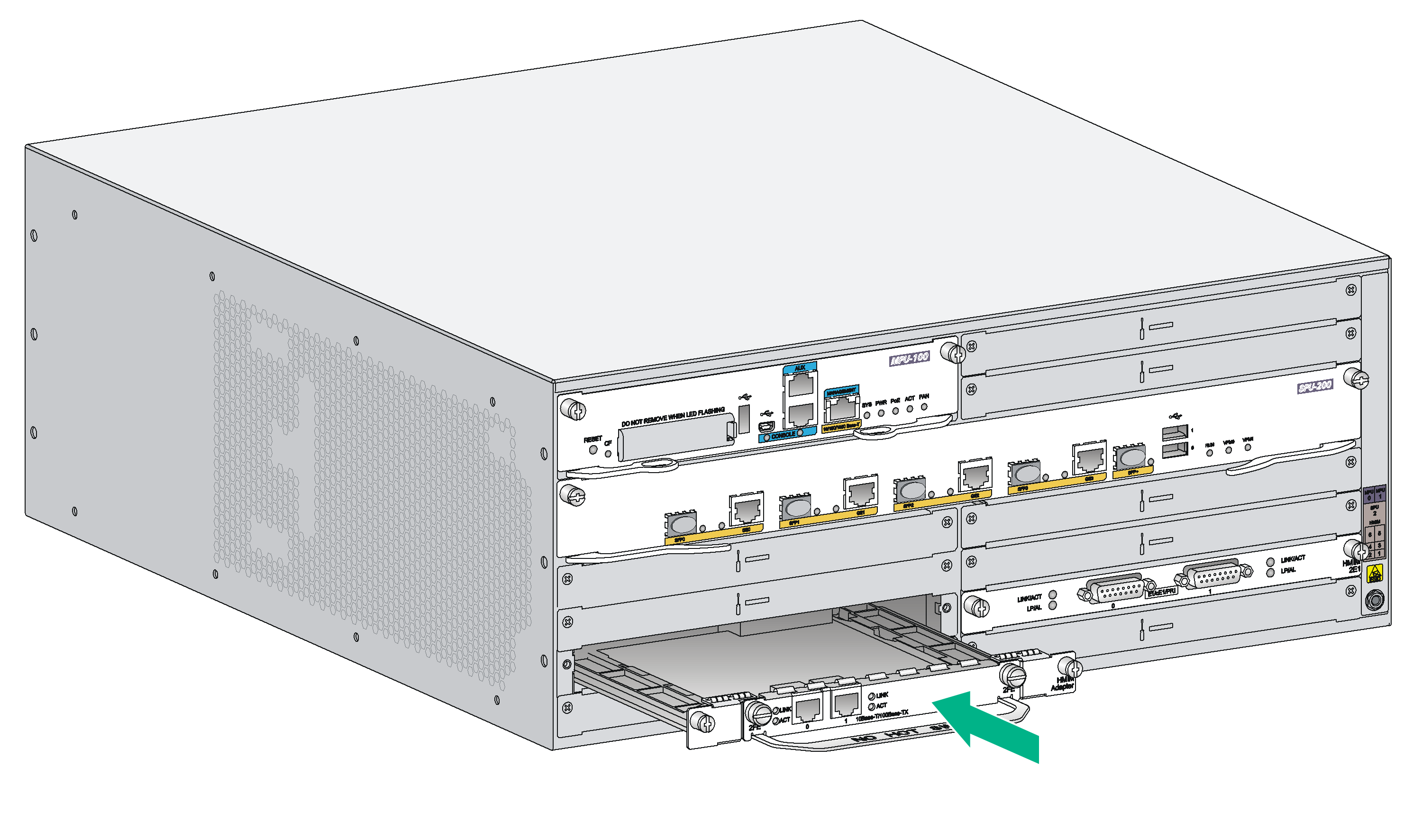
The procedures for installing MIMs on the MSR5620, MSR 56-60, and MSR 56-80 routers are similar. This section describes installation of MIM 2FE on the MSR 56-60.
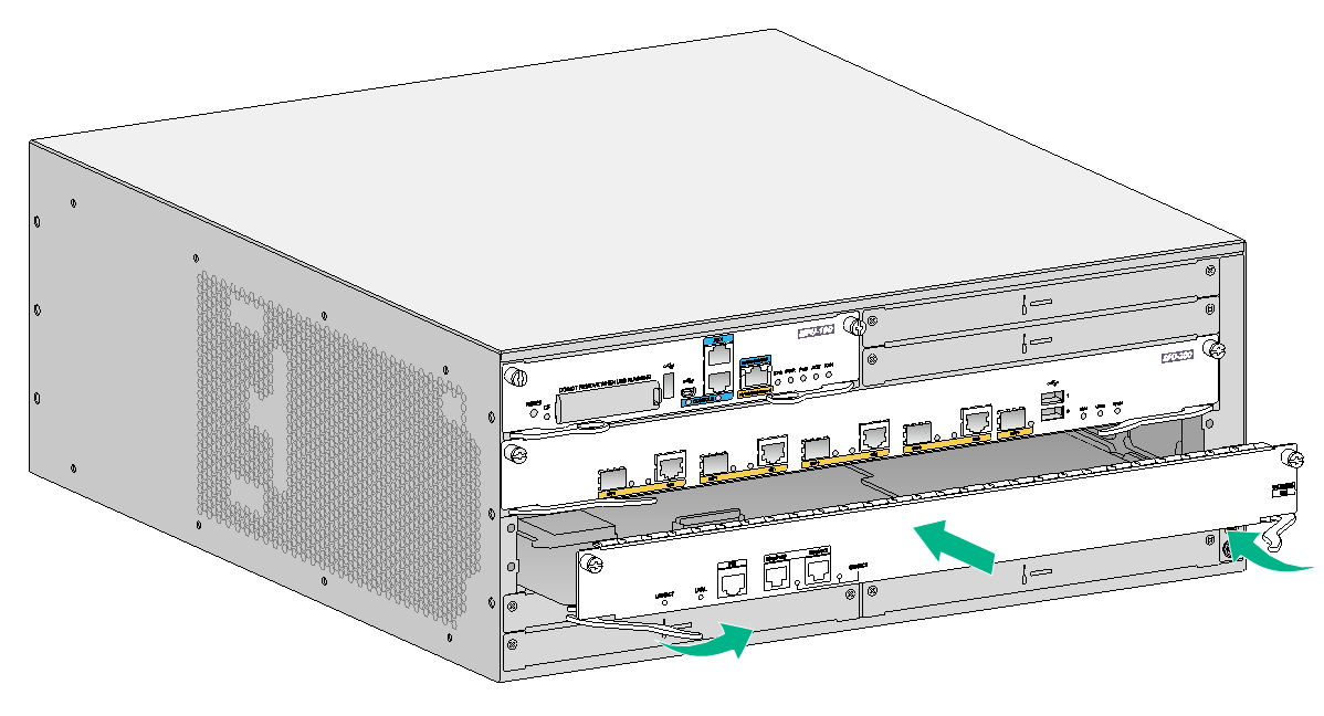
To install a MIM:
1. Remove the fastening screws with a Phillips screwdriver to remove the filler panel.
Keep the removed filler panel and screws in an anti-static bag for future use.
2. Push the MIM slowly along the slide rails until it makes close contact with the backplane of the HMIM adapter, and use screws to secure the MIM to the HMIM adapter.
3. Fasten the captive screws on the MIM to secure it to the HMIM adapter.
Figure2-36 Attaching a MIM to an HMIM adapter

|
(1) HMIM adaptor |
(2) Install MIM to the HMIM adapter |
4. Push the MIM into the slot along the slide rails until it makes close contact with the backplane of the router.
5. Fasten the captive screws to secure the MIM to the router.
Figure2-37 Installing the MIM on the router
Installing a DHMIM
|
|
IMPORTANT: · For a DHMIM to be identified by the system, make sure an SPU has been installed on the device before installing the DHMIM on an MSR 56-60 or MSR 56-80 router. · You can install a DHMIM while the router is operating. Before you remove a DHMIM on an operating router, execute the remove command. Do not remove the DHMIM until the system displays a message that the DHMIM can be removed. For the DHMIM replacement procedure, see "Replacing a DHMIM." |
Only the MSR 56-60 and MSR 56-80 routers support DHMIM installation. You can install a DHMIM on the MSR 56-60 router after you remove the slot divider between slot 5 and slot 6. You can install two DHMIMs on the MSR 56-80 router after you move the slot dividers between slot 5 and slot 6 and between slot 7 and slot 8.
The following procedure describes installing a DHMIM in slots 5 and 6 on the MSR 56-60 router.
To remove a DHMIM:
1. Use a Phillips screwdriver to remove the captive screws on the filler panels in slots 5 and 6 and then remove the filler panels.
Keep the filler panels secure.
Figure2-38 Removing the filler panels
2. Pinching the spring tabs on the two sides of the slot divider, pull the slot divider out of the slot along the guide rails.
Figure2-39 Removing the slot divider
3. Push the DHMIM slowly into the slot along the guide rails and close the ejector levers. Make sure the DHMIM is fully seated in the slot.
Figure2-40 Installing the DHMIM
4. Fasten the captive screws on the DHMIM.
Installing a power supply
|
|
CAUTION: To install multiple power supplies for the router, make sure all power supplies are AC input or DC input. |
|
|
IMPORTANT: Determine the quantity of power supplies based on the types and quantities of the MPUs, service modules, and interface modules selected for the router. Make sure the total output capacity of the power supplies is greater than the system power consumption. For the capacities of the power supplies and power consumptions of the MPUs, service modules, and interface modules, see H3C MSR 5600 Routers Hardware Information and Specifications. |
The power supplies available for the router are hot swappable.
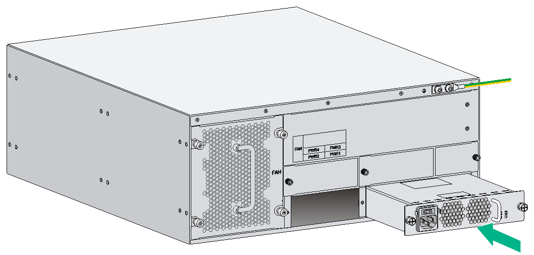
Installing an AC/DC power supply
1. Face the front of the router and locate the slot to be used.
2. Loosen the captive screws with a Phillips screwdriver to remove the filler panel from the slot.
Keep the removed filler panel for future use.
Skip this step if the power supply slot does not have a filler panel when the router is shipped.
3. Holding the handle of the power supply with one hand and supporting the bottom of the power supply with the other hand, insert the power supply slowly along the slide rails until it makes close contact with the backplane.
4. Use a Phillips screwdriver to fasten the captive screws on the two sides of the power supply.
Figure2-41 Installing an AC power supply
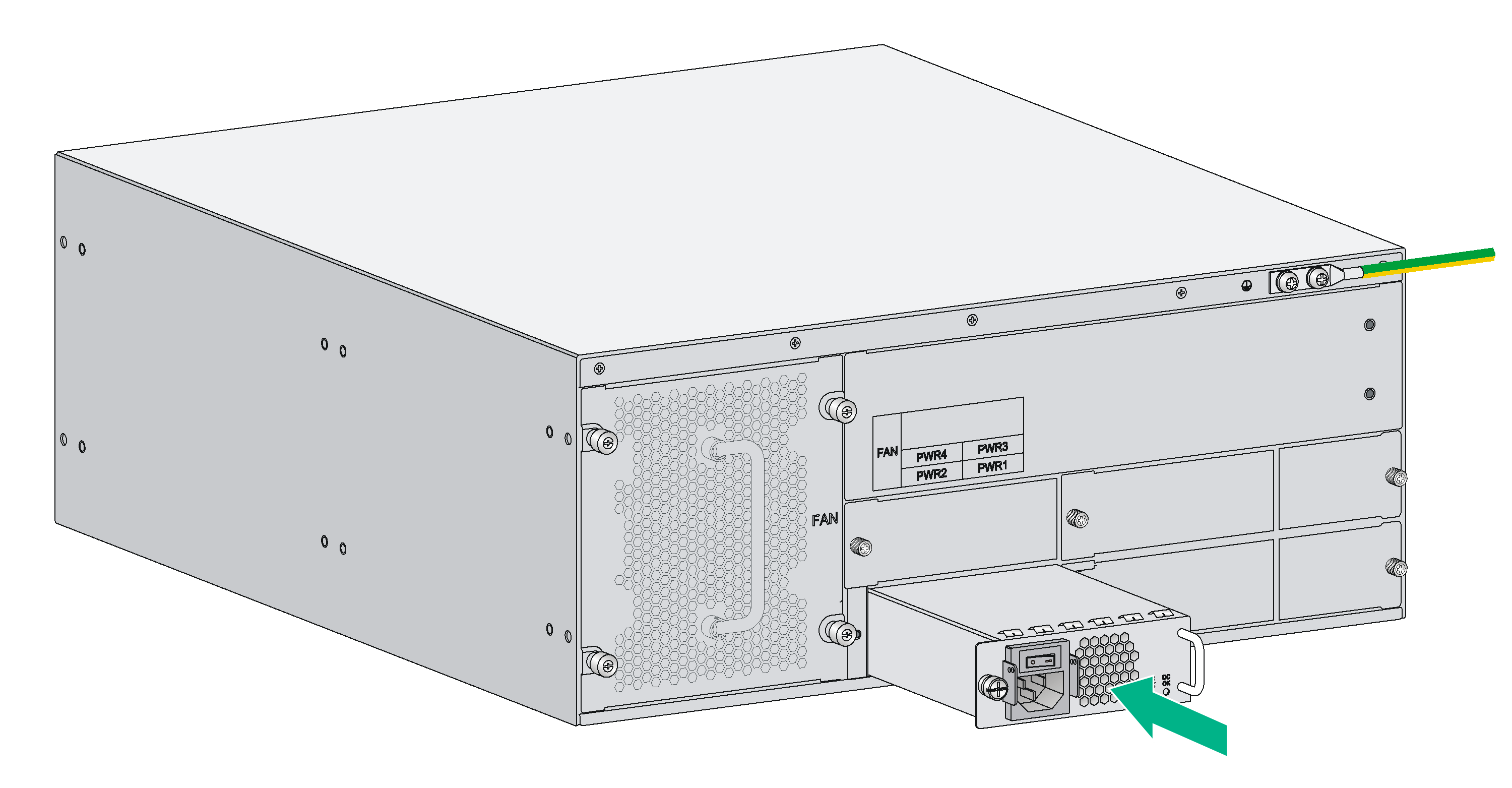
Figure2-42 Installing a DC power supply

Installing a PoE power supply
The MSR 5660 and MSR 5680 routers support PoE power supply to PDs only when they are installed with an HMIM-24GSWP interface module and a PoE power supply. To supply PoE power to PDs, you need to also enable PoE and configure PoE settings on the router. For more information about configuring PoE, see H3C MSR Router Series Comware 7 Network Management and Monitoring Configuration Guide.
For the slots that support the HMIM-24GSWP, see H3C MSR Router Series Comware 7 Interface Module Guide.
1. Face the front of the router and locate the slot to be used.
2. Loosen the captive screws with a Phillips screwdriver to remove the filler panel from the slot.
Keep the removed filler panel for future use.
Skip this step if the PoE power supply slot does not have a filler panel when the router is shipped.
Figure2-43 Removing the filler panel
3. Holding the handle of the power supply with one hand and supporting the bottom of the power supply with the other hand, insert the power supply slowly along the slide rails until it makes close contact with the backplane.
4. Use a Phillips screwdriver to fasten the captive screws on the two sides of the power supply.
Figure2-44 Installing a PoE power supply
Connecting the router to the network
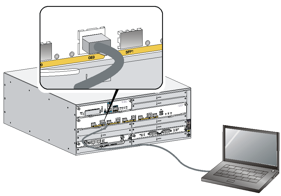
Connect the router to the network before powering on the router. This section describes how to connect the router to the network through Ethernet cables.
Connecting an Ethernet cable
1. Plug one end of an Ethernet twisted pair cable into the copper Ethernet port (RJ-45 port) to be connected on the router.
2. Plug the other end of the cable into the RJ-45 port of the peer device.
Figure2-45 Connecting the router to a PC
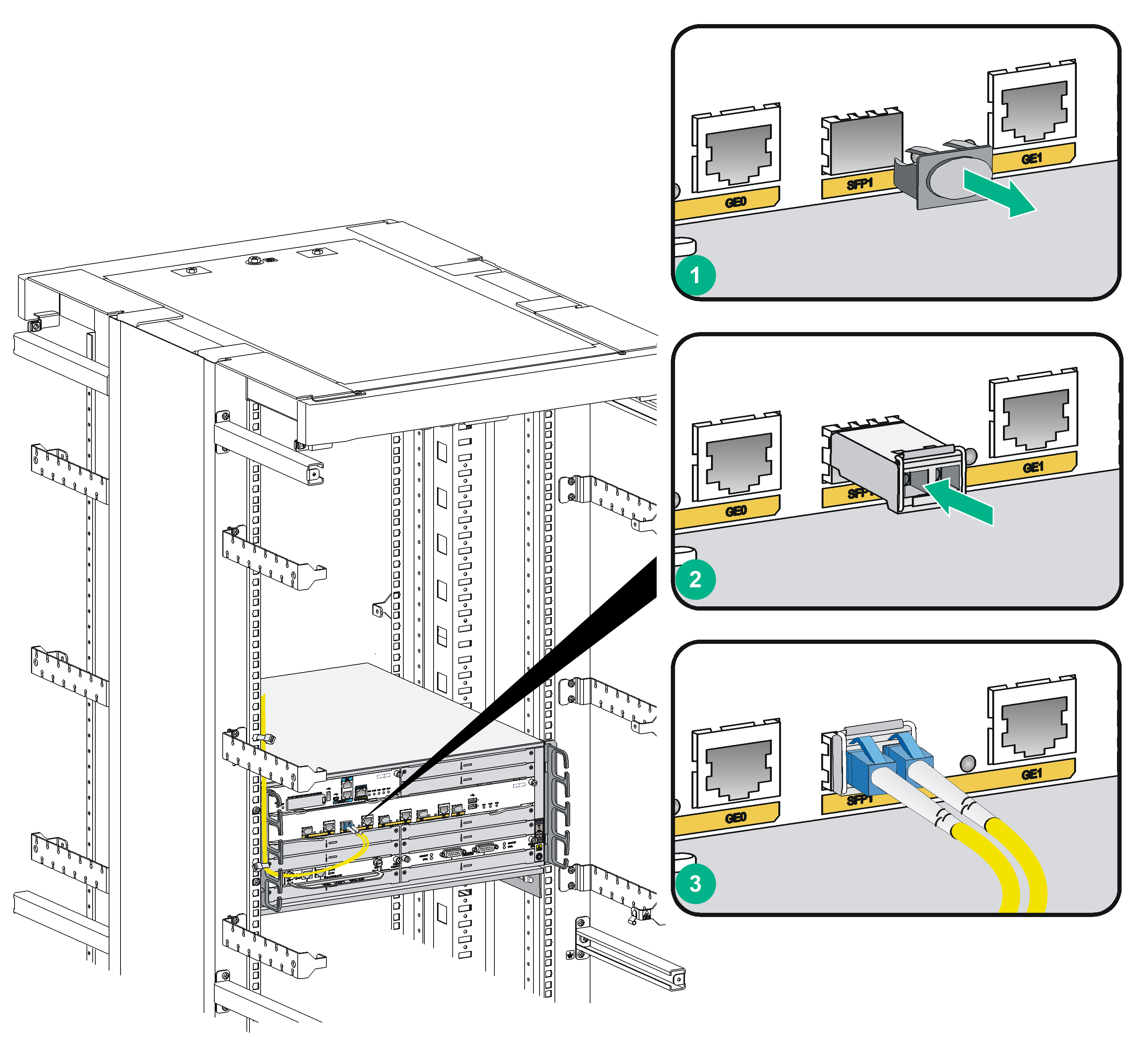
Connecting an optical fiber
|
|
WARNING! Do not stare into any fiber port when you connect an optical fiber. The laser light emitted from the optical fiber may hurt your eyes. |
Follow these guidelines when you connect a fiber cable:
· Never bend or curve a fiber when connecting it.
· Make sure the Tx and Rx ends are correctly connected.
· Keep the fiber end clean.
· Be sure to install the dust cover if the fiber port is not connected to a fiber connector.
To connect an optical fiber:
1. Remove the dust plug from the fiber port.
2. Pivot the pull latch of the transceiver module up so that it catches a knob on the top of the module. Holding two sides of the module, insert the transceiver module into the fiber port.
3. Identify the Rx and Tx ports. Plug the LC connector at one end of one fiber cable into the Rx port of the router and the LC connector at the other end into the Tx port of the peer device. Plug the LC connector at one end of another fiber cable into the Tx port of the router and the LC connector at the other end to the Rx port of the peer device.
4. Examine the Ethernet port LED after connection.
Figure2-46 Connecting an optical fiber
Connecting the power cord
The power cords are for illustration only.
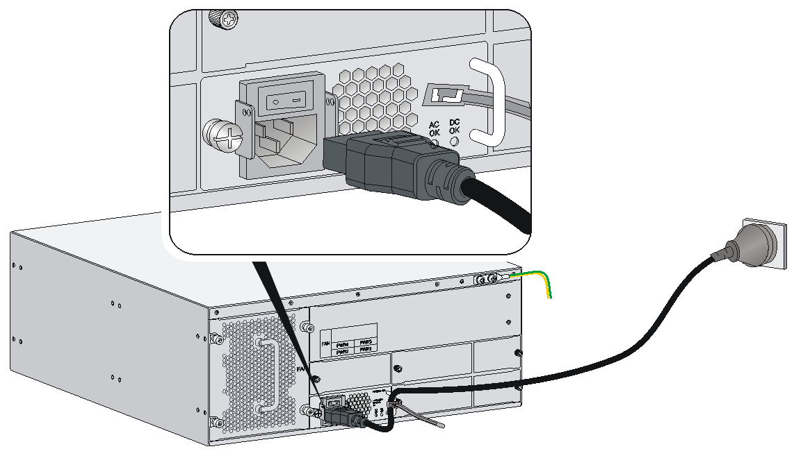
Connecting an AC power cord
1. Make sure the router is reliably grounded, and the power switch on the router is in the OFF position.
2. Connect one end of the AC power cord to the AC receptacle on the router, and the other end to the AC power source.
Figure2-47 Connecting an AC power cord to the router
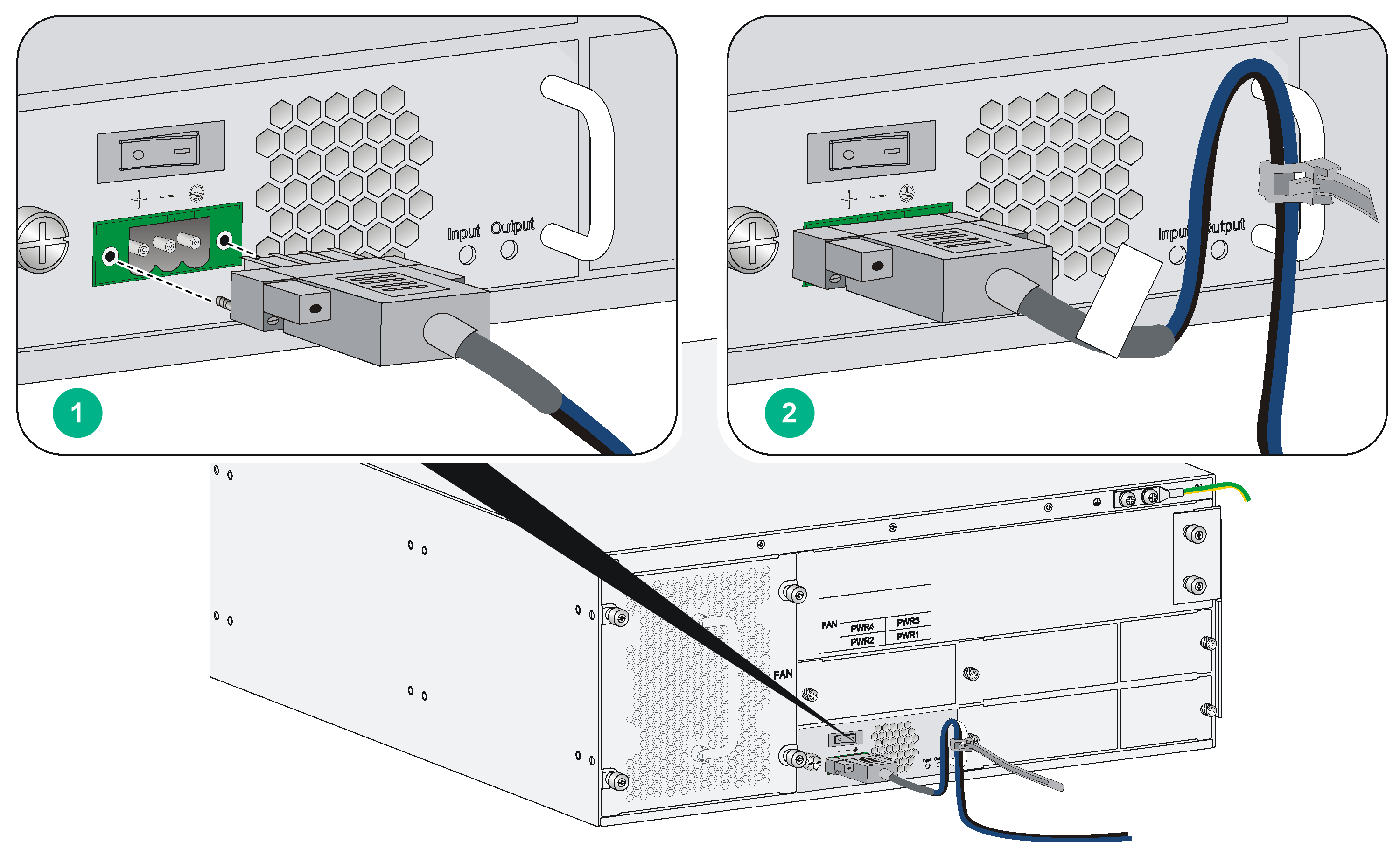
Connecting a DC power cord
|
|
WARNING! Pay attention to the mark on a power cord to avoid connection errors. |
To connect DC power cords:
1. Make sure the router is reliably grounded, and the power switch on the router is in the OFF position.
2. Loosen the captive screws on the power supply with a Phillips screwdriver to remove the power supply connector.
3. Connect one end of the DC power cord supplied with the router to the DC receptacle on the router, and the other end to the DC power source.
Figure2-48 Connecting a DC power cord for the router
Verifying the installation
After you complete the installation, verify the following information:
· There is enough space for heat dissipation around the router, and the rack or workbench is stable.
· USB devices and interface modules are correctly installed.
· The router, rack, and power cords are reliably grounded.
· The correct power source is used.
Starting and configuring the router
Connecting the console cable and setting terminal parameters
To access the router for the first time, use a serial port console cable to connect the console port on the router or use a USB console cable to connect the USB console port.
You can only access the MSR5620 by using a serial port console cable.
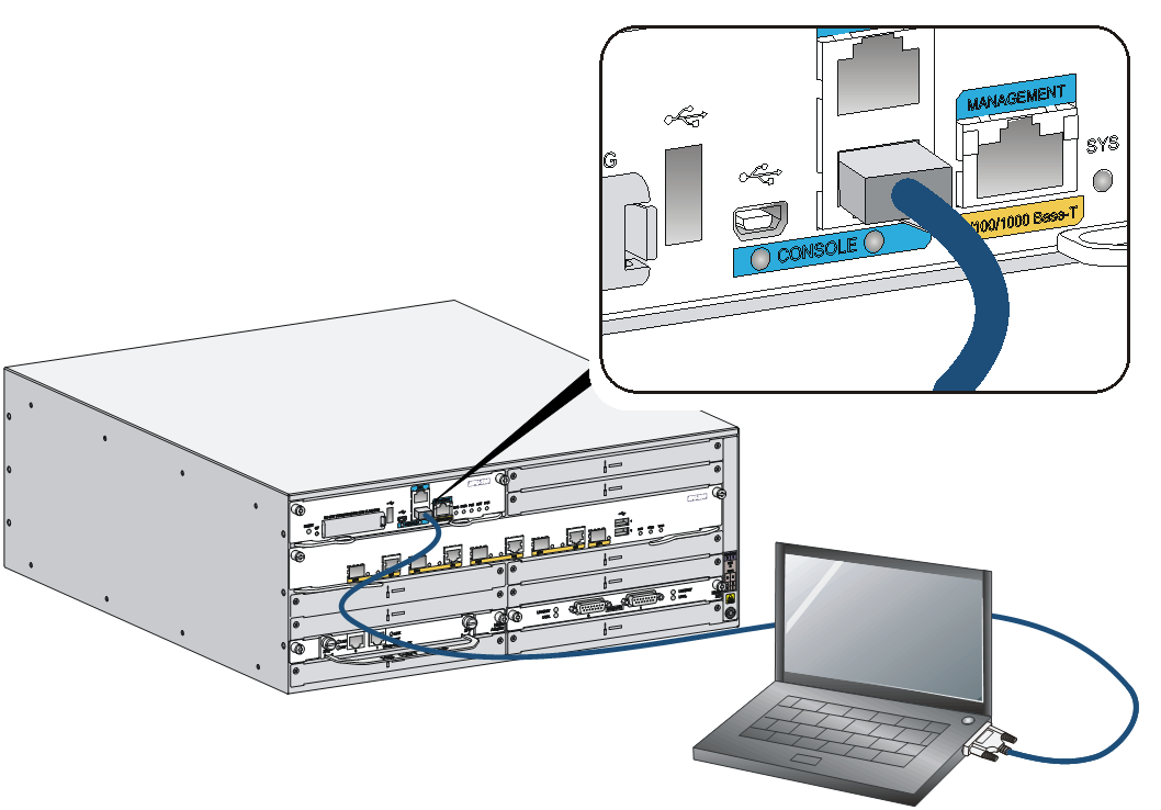
Connecting the serial port console cable
|
|
CAUTION: The serial ports on PCs do not support hot swapping. To connect a PC to an operating router, first connect the PC end. To disconnect a PC from an operating router, first disconnect the router end. |
To connect a serial port console cable:
1. Plug the DB-9 female connector to the RS-232 port on the configuration terminal.
If the configuration terminal does not have an RS-232 port but has a USB port, use a USB-to-RS-232 converter on the USB port and install the correct driver program.
2. Connect the RJ-45 connector to the console port of the router.
Figure2-49 Connecting the serial port console cable
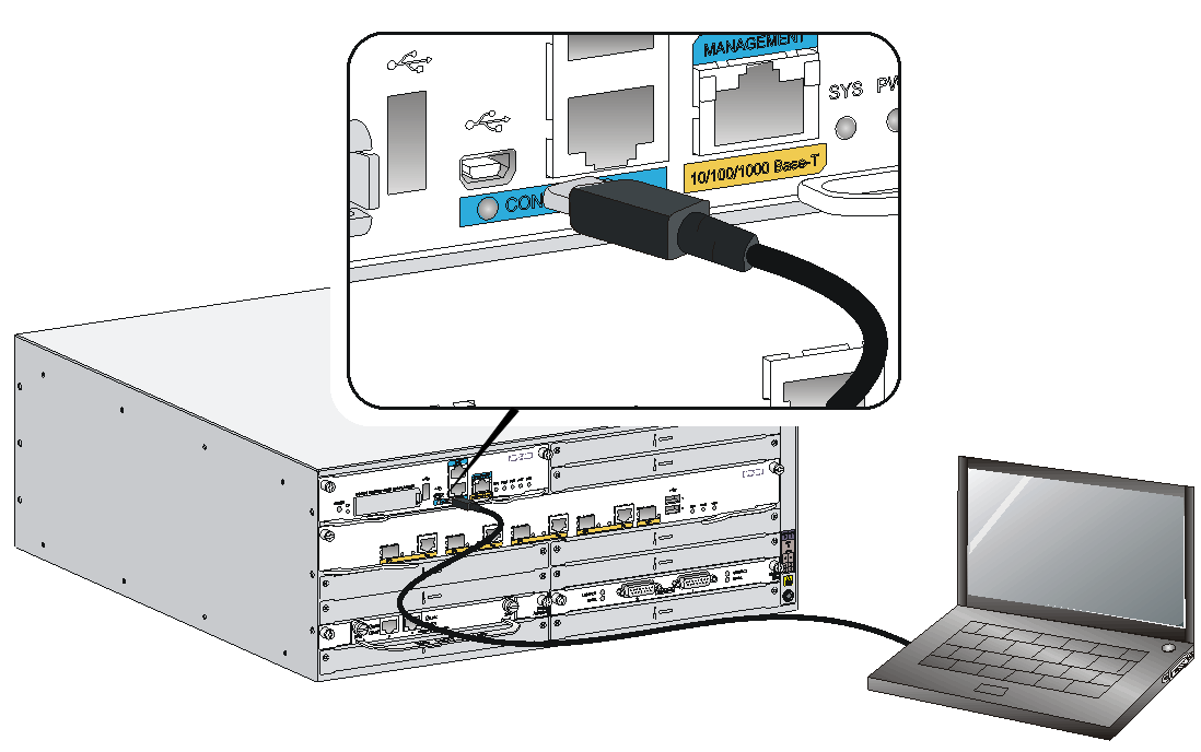
Connecting a USB console cable
|
|
IMPORTANT: Download and install the USB console driver program before configuring the device if you connect the device through a USB console cable. |
The router supports only mini USB console cable.
To connect a USB console cable:
1. Connect the USB port to the PC.
2. Connect the other end to the USB console port of the router.
Figure2-50 Connecting the USB cable
3. Click the following link, or copy it to the address bar on the browser to log in to download page of the USB console driver, and download the driver.
4. Select a driver program according to the operating system you use:
¡ XR21V1410_XR21B1411_Windows_Ver1840_x86_Installer.EXE—Applicable to 32-bit operating systems.
¡ XR21V1410_XR21B1411_Windows_Ver1840_x64_Installer.EXE—Applicable to 64-bit operating systems.
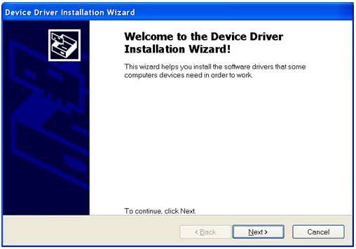
5. Click Next on the installation wizard.
Figure2-51 Device Driver Installation Wizard
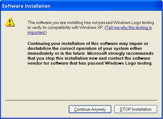
6. Click Continue Anyway if the following dialog box appears.
Figure2-52 Software Installation
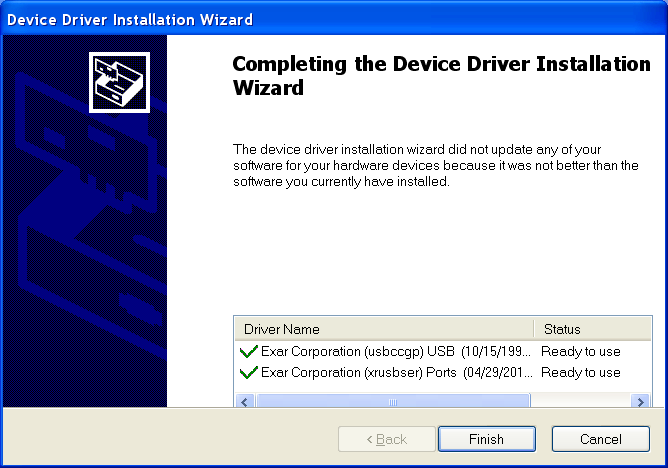
7. Click Finish.
Figure2-53 Completing the device driver installation wizard
Setting terminal parameters
To access the device through the console port, you must run a terminal emulator program (HyperTerminal, PuTTY, or Tera Term) on the configuration terminal. For information about using a terminal emulator program, see the program's user guide.
The following are the required terminal settings:
· Baud rate—9600.
· Data bits—8.
· Stop bits—1.
· Parity—none.
· Flow control—none.
Accessing the router for the first time
|
|
WARNING! Before powering on the router, locate the switch for the power source so that you can cut off power promptly in case of an emergency. |
To access the router for the first time:
1. Verify the installation and configuration environment is as described in "Verifying the installation."
2. Power on the router.
3. During the booting process, verify the following items:
¡ The LEDs on the front panel of the active MPU indicate normal operation.
¡ The configuration terminal displays information correctly.
The router first initializes its memory at startup and then runs BootWare.
System is starting...
Press Ctrl+D to access BASIC-BOOTWARE MENU...
Press Ctrl+T to start heavy memory test
Booting Normal Extended BootWare........
The Extended BootWare is self-decompressing....Done.
****************************************************************************
* *
* H3C MSR56-60 BootWare, Version 2.61 *
* *
****************************************************************************
Copyright (c) 2004-2017 New H3C Technologies Co., Ltd.
Compiled Date : Dec 23 2015
CPU ID : 0x3
Memory Type : DDR3 SDRAM
Memory Size : 2048MB
BootWare Size : 1024KB
Flash Size : 8MB
cfa0 Size : 497MB
CPLD Version : 3.0
PCB Version : 2.0
BootWare Validating...
Press Ctrl+B to access EXTENDED-BOOTWARE MENU...
Loading the main image files...
Loading file cfa0:/msr56-cmw710-system-e0006p05.bin.........................
..........................Done.
Loading file cfa0:/msr56-cmw710-security-e0006p05.bin....Done.
Loading file cfa0:/msr56-cmw710-voice-e0006p05.bin......Done.
Loading file cfa0:/msr56-cmw710-data-e0006p05.bin....Done.
Loading file cfa0:/msr56-cmw710-boot-e0006p05.bin.......................
Done.
Image file cfa0:/msr56-cmw710-boot-e0006p05.bin is self-decompressing.......
........Done.
System image is starting...
Line con1 is available.
Press ENTER to get started.
4. Press Enter. The router is ready to configure when you see the following prompt:
<H3C>
5. Configure basic settings for the router.
For information about configuring basic setting for the router, see H3C MSR Router Series Comware 7 Fundamentals Configuration Guides and H3C MSR Router Series Comware 7 Fundamentals Command References.
3 Replacement procedure
|
IMPORTANT: · The barcode on the router chassis contains product information that must be provided to local sales agent before you return a faulty router for service. · Keep the tamper-proof seal on a mounting screw on the chassis cover intact, and if you want to open the chassis, contact H3C for permission. Otherwise, H3C shall not be liable for any consequence. |
Replacing a power supply
Power supplies are hot swappable.
The replacement procedure of an AC power supply is the same as a DC power supply. This section uses an AC power supply as an example.
To replace a power supply:
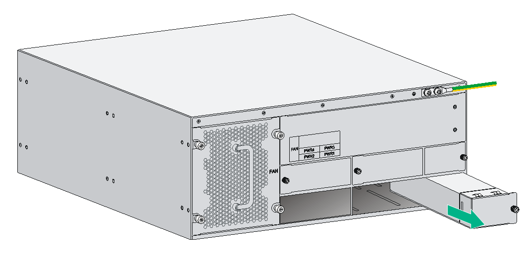
1. Locate the power supply to be removed and use a Phillips screwdriver to completely loosen the captive screws of the power supply.
2. Holding the handle of the power supply with one hand and supporting the bottom of the power supply with the other hand, gently pull the power supply out of the slot along the slide rails.
Put the removed power supply on an antistatic workbench or into an antistatic bag.
Figure3-1 Pulling a power supply out of the slot

3. Install a new power supply. For the installation procedure, see "Installing a power supply."
Install a filler panel if you do not install a new power supply.
Replacing a fan tray
|
|
CAUTION: This section is not applicable to the MSR5620 router because the fan trays in the MSR5620 router are not removable. |
To replace a fan tray:
1. Face the rear panel of the router.
2. Use a Phillips screwdriver to loosen the captive screws of the fan tray.
3. Holding the handle of the fan tray with one hand and supporting the bottom of the fan tray with the other hand, gently pull the fan tray out of the slot along the slide rails.
Figure3-2 Removing a fan tray

4. Install a new fan tray. Holding the handle of the fan tray with one hand and supporting the bottom of the fan tray with the other hand, gently push the fan tray into the slot along the slide rails.
5. Use a Phillips screwdriver to fasten the captive screws of the fan tray.
Replacing an SPU and an SPE
|
|
CAUTION: · SPUs are not hot swappable. Make sure the router is powered off before installing an SPU. · SPEs are hot swappable. However, hot-swapping an SPE is not allowed while an MPU-100-X1 is starting up. · Do not perform any active/standby SPE switchover operations when the system LED on an MPU flashes yellow and green alternatively. |
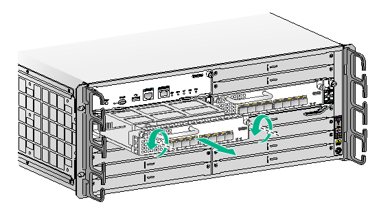
Replacing an SPU
MSR5620 routers do not support SPU replacement. This section describes replacing an SPU-200 for an MSR 56-60 router. Follow the same procedure to replace SPUs for an MSR 56-80 router.
To use an SPU-600-X1, a minimum of one SPE is required.
To replace an SPU:
1. Use a Phillips screwdriver to loosen the captive screws of the SPU until the spring pressure is released.
2. Pivot the ejector levers of the SPU outward, and gently pull the SPU out of the slot.
3. Install a new SPU. For the installation procedure, see "Installing an SPU and an SPE."
Figure3-3 Removing the SPU-200
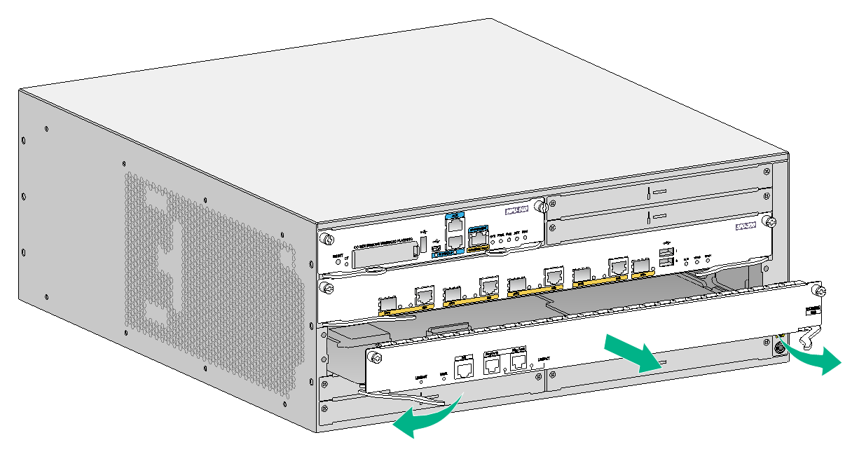
Replacing an SPE
The procedures are the same for replacing an SPE for the MSR 56-60 and MSR 56-80 routers. This section describes replacing an SPE-S3 for an MSR 56-60 router.
To use an SPU-600-X1, a minimum of one SPE is required.
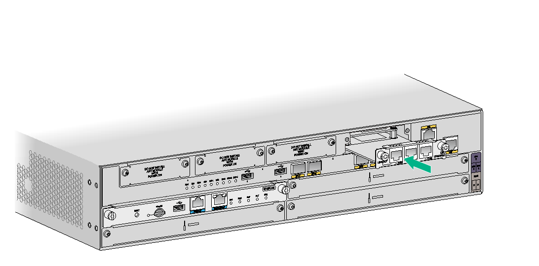
To replace an SPE:
1. Use a Phillips screwdriver to loosen the captive screws of the SPE until the spring pressure is released.
2. Pivot the ejector levers of the SPE outward, and gently pull the SPE out of the slot.
3. Install a new SPE. For the installation procedure, see "Installing an SPU and an SPE."
Figure3-4 Removing the SPE-S3
Replacing an MPU
|
|
CAUTION: · MPUs are hot swappable. Before you remove an MPU installed with a storage medium on an operating router, use the umount command to unmount the file system and wait until the system displays a message that the file system has been unmounted. · Do not perform any active/standby MPU switchover operations when the system LED on an MPU flashes yellow and green alternatively. |
Replacing an MPU from an MSR5620
The MPU-60 is available for the MSR5620 router.
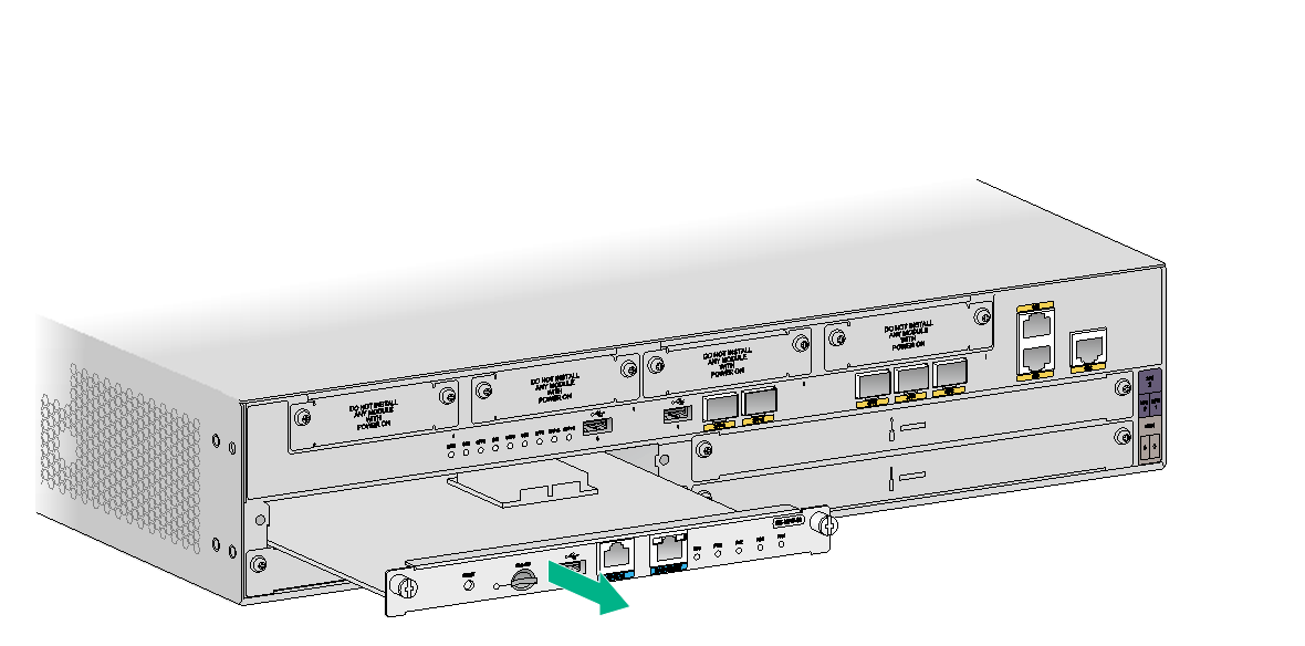
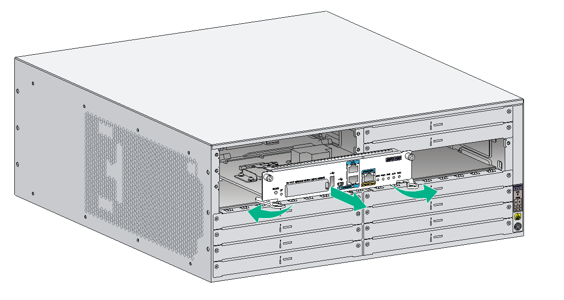
To replace an MPU-60 from an MSR5620 router:
1. Execute the umount sdb0: command in user view to unmount the file system and wait until the system displays a message that the file system has been unmounted.
If no external Micro SD card is installed on the MPU or the router is powered off, skip this step.
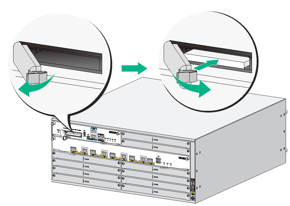
2. Use a Phillips screwdriver to loosen the captive screws on the MPU until the spring pressure is released.
3. Gently pull the MPU out of the slot along the guide rails.
4. Install a new MPU. For the installation procedure, see "Installing an MPU."
Figure3-5 Removing an MPU-60
Replacing an MPU from an MSR 56-60/80 router
|
|
CAUTION: · Before you remove an MPU-100 on an operating router, unmount the file systems and wait until the system outputs a message that the file systems have been unmounted. ¡ If no external CF card is installed on the MPU, execute the umount cfa0: command to unmount the file system. ¡ If an external CF card is installed on the MPU, execute the umount cfa0: and umount cfb0: commands to unmount the file systems. · Before you remove an MPU-100-X1 on an operating router, unmount the file systems and wait until the system outputs a message that the file systems have been unmounted. ¡ If no external Micro SD card is installed on the MPU, execute the umount sdb0: command to unmount the file system. ¡ If an external Micro SD card is installed on the MPU, execute the umount sda0: and umount sdb0: commands to unmount the file systems. |
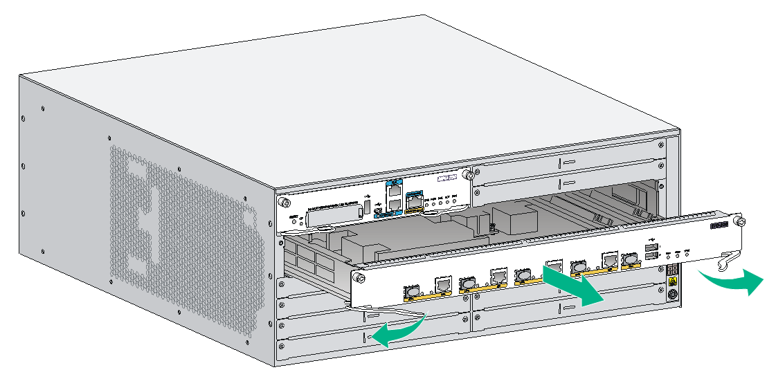
The MSR 56-60 and MSR 56-80 routers support the MPU-100, MPU-100-X1, and MPU-100-G. The MPU replacement procedure is similar for the MSR 56-60 and MSR 56-80 routers. The following procedure describes replacing an MPU-100 on an MSR 56-60 router.
To replace an MPU-100 on an MSR 56-60 router:
1. Unmount the file systems and wait until the system outputs a message that the file systems have been unmounted.
¡ If no external CF card is installed on the MPU, execute the umount cfa0: command in user view to unmount the file system.
¡ If an external CF card is installed on the MPU, execute the umount cfa0: and umount cfb0: commands in user view to unmount the file systems.
If the router is powered off, skip this step.
2. Use a Phillips screwdriver to loosen the captive screws of the MPU until the spring pressure is released.
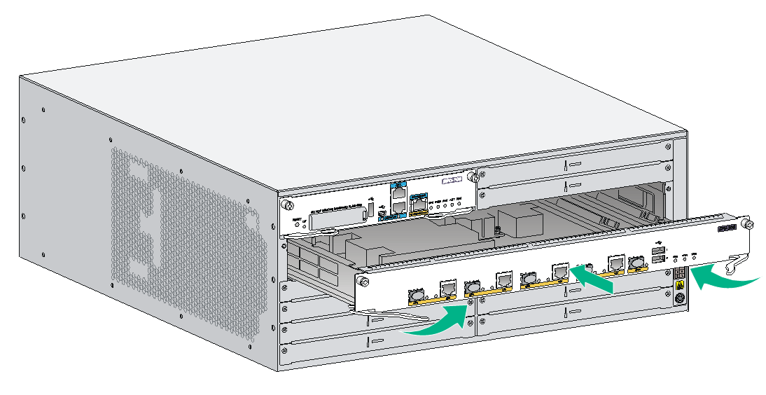
3. Pivot the ejector levers of the MPU outward, and gently pull the MPU out of the slot.
4. Install a new MPU. For the installation procedure, see "Installing an MPU."
Figure3-6 Removing the MPU-100
Replacing a VPM
|
|
IMPORTANT: Before you replace a VPM, remove the SPU from the chassis. For information about removing an SPU, see "Replacing an SPU." |
Only the SPU-100, SPU-200, and SPU-300 service modules support VPMs.
VPM (Voice Processing Module) functions to implement the encryption/decryption, EC and CNG of voices. The following types of VPM modules are available on the MSR 5600 routers:
· 256-channel voice processing module (256-VPM)
· 512-channel voice processing module (512-VPM)
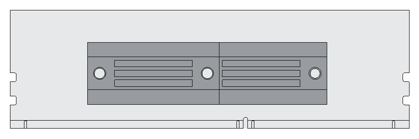
Figure3-8 SPU-200 structure
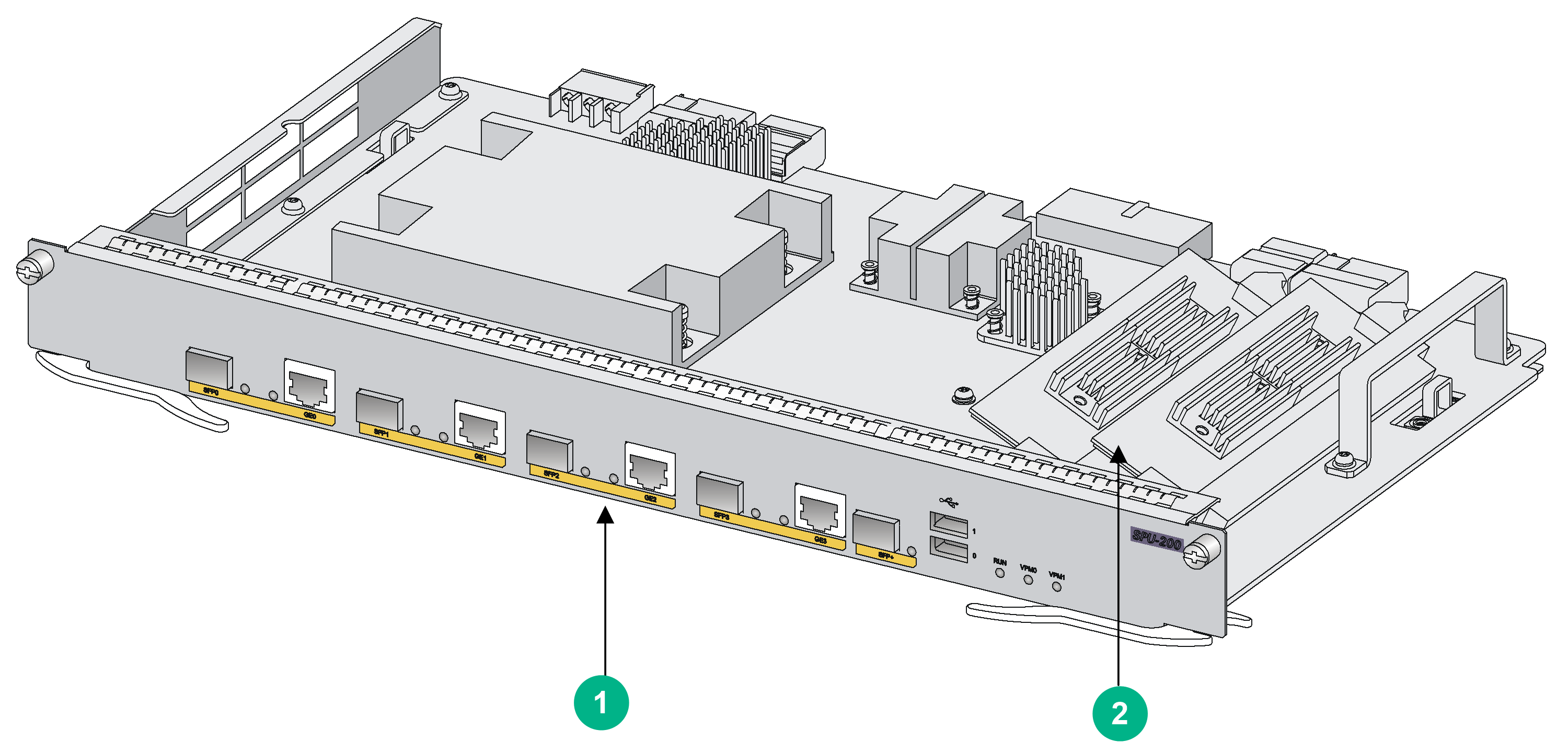
|
(1) Front panel |
(2) VPM |
1. Pull the release latches away from the VPM at both ends so that the VPM springs up from the slot.
2. Holding the non-conductive edge, remove the VPM.
Keep the removed VPM for future use.
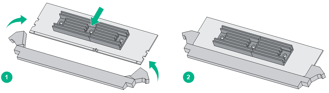
3. Align the polarization notch of a new VPM with the VPM slot on the main board and insert it into the slot along the slide rails.
4. Carefully and firmly press the VPM at both ends until you hear a click. This indicates the VPM is seated in the slot.
5. Verify that the release latches have firmly locked the VPM in position.
Figure3-9 Removing a VPM
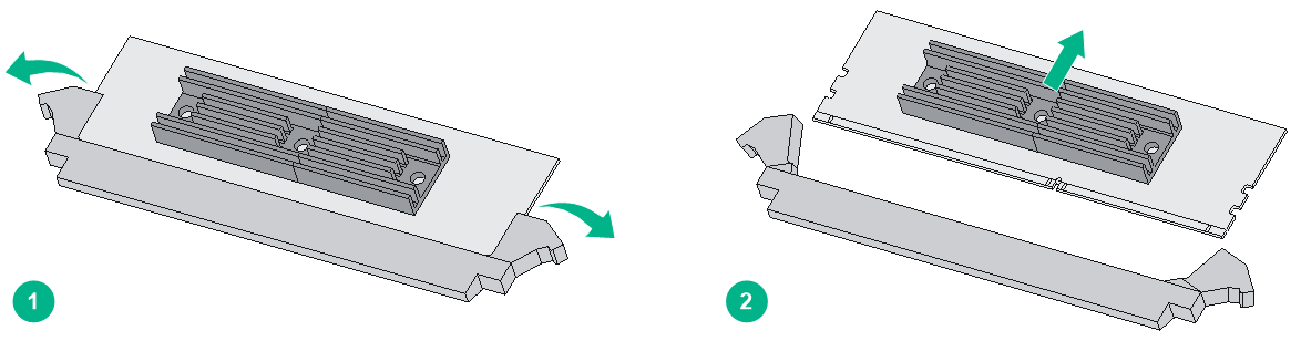
Figure3-10 Installing a VPM
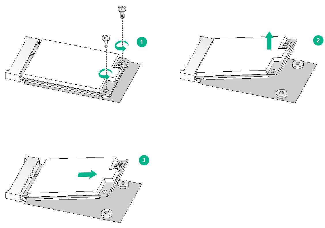
Replacing an SSD drive
|
|
CAUTION: Before you remove an SSD drive, remove the MPU from the router. For the MPU removal procedure, see "Replacing an MPU." |
To remove an SSD drive:
1. Use a Phillips screwdriver to remove the fastening screws on the SSD drive.
2. Gently lift the SSD drive free from the connector.
Keep the SSD secure.
3. Install a new SSD drive. For the installation procedure, see "Installing an SSD drive."
Figure3-11 Removing an SSD drive
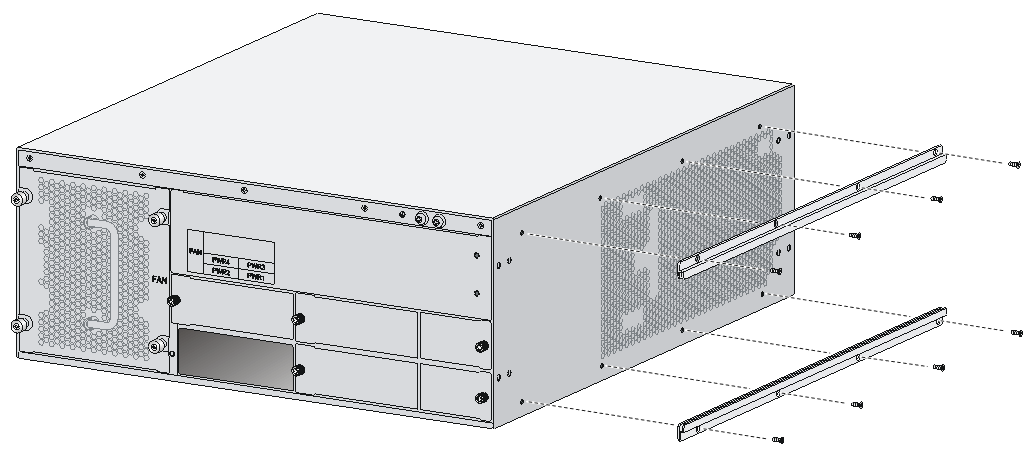
Replacing an air filter
1. Use a Phillips screwdriver to completely loosen the captive screws of the air filter.
2. Gently pull the air filter out along the slide rails.
Figure3-12 Removing an air filter

3. Install a new air filter. For the installation procedure, see "Installing the router."
To remove the slide rails, completely loosen the fastening screws of the slide rails.
To install new slide rails, see "Installing an air filter."
Figure3-13 Removing slide rails
Replacing an external CF card
|
|
CAUTION: Before you remove an external CF card on an operating router, execute the umount cfb0: command. |
To replace a CF card:
1. Execute the umount cfb0: command in user view to unmount the file system and wait until the system displays a message that the file system has been unmounted.
Skip this step if the router is powered off.
2. Press down the spring clip of the CF card cover and open the cover.
3. Press the CF card eject button of the CF card reader so that the eject button projects from the panel.
4. Press the eject button again to eject the CF card part-way out of the CF card reader, and then pull the CF card out of the CF card reader.
Keep the removed CF card for future use.
5. Install a new CF card. For the installation procedure, see "Installing a CF card."
If you do not install a new CF card, close the CF card cover.
Figure3-14 Removing a CF card
Replacing an external Micro SD card
|
|
CAUTION: You can install a Micro SD card while the router is operating. To avoid Micro SD card damage and data loss, execute the umount sdb0 command before you remove a Micro SD card on an operating router. |
To replace a Micro SD card:
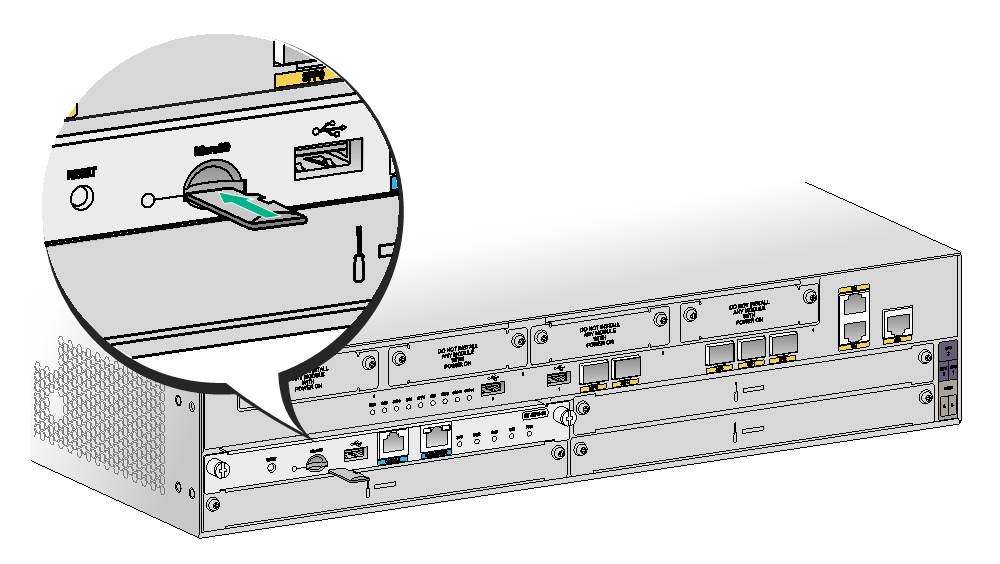
1. Execute the umount sdb0: command in user view to unmount the file system and wait until the system displays a message that the file system has been unmounted.
Skip this step if the router is powered off.
2. Pull out the Micro SD card along the guide rails from the slot.
Keep the removed Micro SD card for future use.
3. Install a new Micro SD card. For the installation procedure, see "Installing a Micro SD card."
Figure3-15 Removing the Micro SD card

Replacing a SIC
|
|
CAUTION: SIC interface modules are not hot swappable. Make sure the router is powered off before installing a SIC. |
To replace a SIC:
1. Completely loosen the captive screws of the SIC.
2. Gently pull the SIC out along the guide rails.
3. Install a new SIC. For the installation procedure, see "Installing a SIC."
If you do not install a SIC, install a filler panel and tighten the screws.
Figure3-16 Pulling a SIC out

Replacing an HMIM
|
|
CAUTION: Before you remove an HMIM on an operating router, execute the remove command. |
To replace an HMIM:
1. Execute the remove command in user view and wait until the message "You can remove the card now!" is displayed.
Skip this step if the router is powered off.
2. Completely loosen the captive screws of the HMIM.
3. Gently pull the HMIM out of the slot along the slide rails.
4. Install a new HMIM. For the installation procedure, see "Installing an HMIM."
If you do not install a new HMIM, install a filler panel and tighten the screws.
Figure3-17 Pulling the HMIM out of the slot

Replacing a MIM
|
|
CAUTION: Before you remove an HMIM on an operating router, execute the remove command. |
|
|
CAUTION: Before you remove an HMIM on an operating router, execute the remove command. |
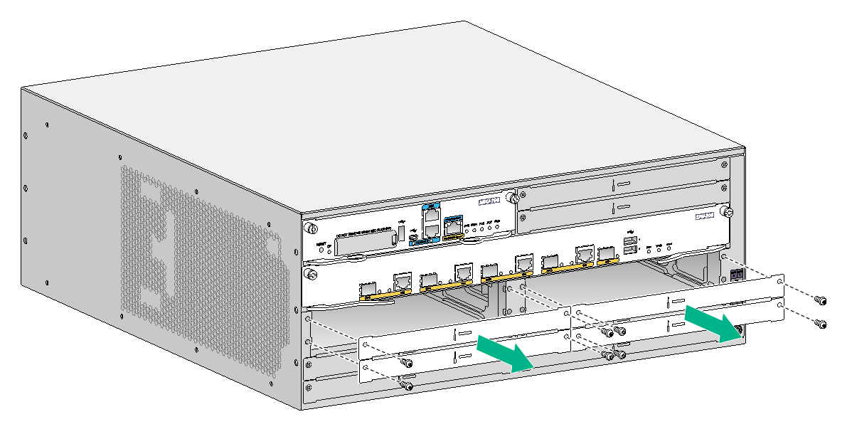
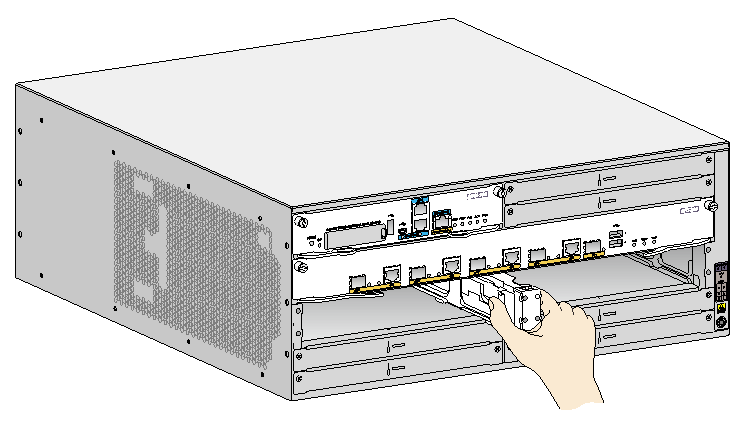
To replace a MIM:
1. Execute the remove command in user view and wait until the message "You can remove the card now!" is displayed.
Skip this step if the router is powered off.
2. Completely loosen the captive screws of the HMIM adapter.
3. Gently pull the MIM and the HMIM adapter out of the slot along the slide rails.
Figure3-18 Removing a MIM and the HMIM adapter

4. Completely loosen the captive screws of the MIM, loosen and take off the screws securing the MIM to the HMIM adapter, and pull the MIM out of the HMIM adapter along the slide rails.
Keep the removed MIM for future use.
5. Install a new MIM. For the installation procedure, see "Installing a MIM."
If you do not install a new MIM in the slot, install a filler panel and tighten the screws.

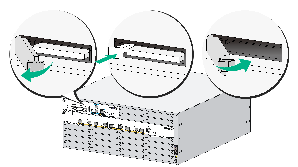
Replacing a DHMIM
|
|
CAUTION: Before you remove a DHMIM on an operating router, execute the remove command. |
To replace a DHMIM:
1. Execute the remove command in user view and wait until the message "You can remove the card now!" is displayed.
Skip this step if the router is powered off.
2. Loosen the captive screws on the DHMIM. Simultaneously open the ejector levers on the two sides of the DHMIM, and pull the DHMIM slowly out of the slot along the guide rails.
Figure3-20 Removing a DHMIM
3. Install a new DHMIM in the slot. For the installation procedure, see "Installing a DHMIM."
4. If you are not to install a new DHMIM in the slot, perform the following tasks:
a. Insert a slot divider into the slot along the guide rails in the middle.
Figure3-21 Installing a slot divider in the slot

b. Install HMIM filler panels on the slots and fasten the screws.
Figure3-22 Installing HMIM filler panels on the slot
4 Troubleshooting
|
|
IMPORTANT: · The barcode on the router chassis contains product information that must be provided to local sales agent before you return a faulty router for service. · Keep the tamper-proof seal on a mounting screw on the chassis cover intact, and if you want to open the chassis, contact H3C for permission. Otherwise, H3C shall not be liable for any consequence. |
Power supply system failure
Symptom
The router cannot be powered on. The power LED is off.
Solution
To resolve the issue:
1. Turn off the power switch of the power source.
2. Verify that the power cord of the router is correctly connected to the router and the power source.
3. Verify that the power source is operating correctly.
4. Verify that the power cord is in good condition.
5. If the issue persists, contact H3C Support.
Fan tray failures
Symptom
After the router starts up, the following error message appears on the configuration terminal:
%Jun 22 16:11:37:485 2015 H3C DEV/4/FAN FAILED:
Fan 1 failed.
Solution
To resolve the issue:
1. Verify that the fan trays are correctly installed.
2. Verify that no obstacle enters the chassis and blocks the fans.
3. Verify that no fan stops rotating. If a fan stops rotating without being blocked, contact H3C Support to replace the fan.
4. If the issue persists, power off the router and contact H3C Support.
Configuration system failures
If the router operates correctly after being powered on, the boot information is displayed on the configuration terminal. If the configuration system is faulty, the configuration terminal displays garbled characters or does not display anything.
No display on the configuration terminal
Symptom
After the router is powered on, the console terminal does not display anything.
Solution
To resolve the issue:
1. Verify that the power supply system is operating correctly.
2. Verify that the console cable is correctly connected.
3. Verify that the console cable is connected to the serial port that is configured for the configuration terminal.
4. Verify that the configuration terminal parameters are configured as follows:
¡ Baud rate—9600.
¡ Data bits—8.
¡ Parity—none.
¡ Stop bits—1.
¡ Flow control—none.
¡ Terminal emulation—VT100.
5. Verify that the console cable is in good condition.
6. If the issue persists, contact H3C Support.
Garbled characters on the configuration terminal
Symptom
After the router is powered on, the configuration terminal displays garbled characters.
Solution
1. Verify that the Data bits field is set to 8 for the configuration terminal.
2. If the issue persists, contact H3C Support.
No response from the serial port
Symptom
No boot information is displayed on the configuration terminal when the router starts up or restarts up.
Solution
1. Verify that the serial cable is in good condition and the serial port properties are correct.
2. If the issue persists, contact H3C Support.
User password loss
Symptom
If you lose your user password, you cannot log in to the system.
Solution
To resolve the issue:
1. Select 8 on the main BootWare menu to clear the console interface login password:
===========================<EXTEND-BOOTWARE MENU>===========================
|<1> Boot System |
|<2> Enter Serial SubMenu |
|<3> Enter Ethernet SubMenu |
|<4> File Control |
|<5> Modify BootWare Password |
|<6> Skip Current System Configuration |
|<7> BootWare Operation Menu |
|<8> Skip authentication for console login |
|<9> Storage Device Operation |
|<0> Reboot |
============================================================================
Enter your choice(0-9):8
The following output indicates that you have successfully cleared the console login password.
Clear Application Password Success!
2. Select 0 from the main BootWare menu to reboot the system.
System is rebooting now.
System start booting...
Booting Normal Extend BootWare....
3. After the system restarts up, set a new password.
<Sysname> system-view
[Sysname] user-interface console 0
[Sysname-ui-console0] authentication-mode password
[Sysname-ui-console0] set authentication password cipher 123456
The commands above configure password authentication for the console user interface and set the ciphertext password 123456.
For security purposes, all keys set with the set authentication password { cipher | simple } password command, including keys configured in plain text, are saved in cipher text.
4. Execute the save command after modifying the user password to save the new password.
[Sysname] save
5. If the issue persists, contact H3C Support.
|
|
NOTE: As a best practice, save the modification as the default configuration file. |
Interface module, cable, and connection failure
Symptom
After an interface module is installed and the router is powered on, the LEDs on the interface module panel indicate that the interface module is operating incorrectly.
Solution
To resolve the issue:
1. Verify that the interface module makes good contact with the rear panel of the router slot.
2. Verify that the router supports the interface module.
3. Verify that the interface module is installed in the specified router slot.
4. Verify that a correct cable is used.
5. Verify that the cable is correctly connected.
6. If the issue persists, contact H3C Support.
System failure during operation
Symptom
The system crashes.
Solution
Press the reset button to reboot the router.
Reset button use guidelines
The reset button can be used only for rebooting the router. It cannot restore the device to factory default.
· When only one MPU runs on the router, pressing the reset button reboots the router.
· When two MPUs run on the router, pressing the reset button on the active MPU will trigger an active/standby MPU switchover without service interruption.
· When two MPUs run on the router, pressing the reset button on the standby MPU will reset the standby MPU without service interruption.
|
|
IMPORTANT: The reset button on an MPU-60 takes effect immediately after you press it. The reset button on the other MPUs takes effect only after you press and hold it for a minimum of 0.5s. |