- Table of Contents
- Related Documents
-
| Title | Size | Download |
|---|---|---|
| 01-MPLS SR configuration | 559.55 KB |
Dynamic SID allocation through an IGP
Label forwarding entry installation based on SIDs
Microloop avoidance after a network failure
Microloop avoidance after a failure recovery
IP traffic forwarding over SRLSPs tasks at a glance
Configuring IGP-based SID advertisement
Prerequisites for configuring IGP-based SID advertisement
Configuring the IGP to support MPLS SR
Enabling MPLS SR adjacency label allocation for the IGP
Configuring the device to prefer SRLSPs in traffic forwarding
Configuring MPLS SR and LDP interworking
Restrictions and guidelines for MPLS SR and LDP interworking
Prerequisites for MPLS SR and LDP internetworking
Enabling advertisement of locally configured prefix-SID mappings
Configuring prefix-SID mappings
Enabling reception of advertised prefix-SID mappings
Restrictions and guidelines for TI-LFA FRR
Disabling an interface from participating in TI-LFA calculation
Configuring microloop avoidance
Display and maintenance commands for MPLS SR
MPLS SR configuration examples
Example: Configuring MPLS SR to LDP (IS-IS)
Example: Configuring MPLS SR over LDP
Example: Configuring IS-IS TI-LFA FRR
Configuring MPLS SR
About MPLS SR
Segment Routing (SR) is a source routing technology. The source node selects a path for the packets, and then encodes the path in the packet header as an ordered list of segments. Each segment is identified by the segment identifier (SID). The SR nodes along the path forward the packets based on the SIDs in the packets. Only the source node needs to maintain the path status.
SR can operate with MPLS. In an MPLS network, SR uses MPLS labels as SIDs to forward packets on an LSP.
MPLS SR characteristics
MPLS SR has the following characteristics:
· MPLS SR forwards packets based on the existing MPLS infrastructure. No infrastructure modifications are needed to implement SR on an MPLS network. For more information about the MPLS infrastructure, see MPLS basics configuration in MPLS Configuration Guide.
· MPLS SR expands and optimizes existing IGPs, and uses the IGPs to distribute labels.
Basic concepts
· SR node—A node enabled with the MPLS SR feature. The ingress node (source node) adds labels to packets. The transit nodes forward packets based on labels. The egress node removes labels and forwards packets to the destination networks. SR nodes form an SR domain.
· Segment—An instruction an SR node executes on the incoming packet.
· SID—Segment ID, which is MPLS label in MPLS SR.
· Segment type—The following types of segments are available:
¡ Prefix segment—SIDs are assigned to nodes based on destination address prefix. The nodes create prefix-specific forwarding entries.
¡ Adjacency segment—SIDs are assigned to nodes based on adjacency.
· SRLSP—Segment routing label switched path, an LSP along which SR uses MPLS labels as SIDs to forward packets.
· SRGB—Segment routing global block, a range of global labels dedicated for MPLS SR prefix SIDs. Different nodes can have different SRGBs. The minimum label value of an SRGB label range is referred to as the base value of the SRGB. Labels 16000 through 24000 are reserved for SRGBs.
· SRLB—Segment routing local block, a range of local labels dedicated for MPLS SR adjacency SIDs. All nodes share the same SRLB. The minimum label value of the SRLB label range is referred to as the base value of the SRLB.
How MPLS SR works
MPLS SR involves the following steps:
1. Dynamic SID allocation. This step allocates labels to all nodes and links along the packet forwarding paths.
2. Label forwarding entry installation based on SIDs. All MPLS SR devices in the SR domain use the allocated labels to create label forwarding entries.
3. SRLSP setup. You can use an IGP to dynamically create SRLSPs.
When the ingress node of an SRLSP receives a packet, it adds labels to the packet and forwards the packet to the egress node through the SRLSP. After receiving a packet from the SRLSP, the egress node removes the label and forwards the packet based on the routing table.
Dynamic SID allocation through an IGP
MPLS SR expands IGP protocols such as IS-IS to advertise SIDs in IGP protocol packets. MPLS SR provides the following methods for dynamically allocating and advertising SIDs:
· Prefix SID—After you configure an SID for the loopback address on each SR node, the SIDs uniquely identify the SR nodes. All SR nodes in the SR domain use an IGP to advertise their own prefix SIDs. After receiving advertised prefix SIDs, each SR node calculates the prefix SIDs to the advertisers.
The prefix SID advertisement can be one of the following types:
¡ Absolute value advertisement—Each SR node advertises the prefix SID absolute value and the SRGB.
¡ Index value advertisement—Each SR node advertises the prefix SID index and the SRGB.
Each SR node is assigned a globally unique index value for the node's prefix. The prefix SID an SR node allocates to a prefix equals the SRBG base of the SR node plus the index for that prefix.
|
|
NOTE: The device supports only the index value advertisement in the current software release. |
· Adjacency SID—SR nodes use an IGP to advertise SIDs allocated to the IGP adjacencies (that is, the links to its IGP neighbors). The SIDs are used to identify the links.
The adjacency SIDs can be allocated automatically or manually.
¡ Automatic adjacency SID allocation—SR nodes allocate labels in SRLBs to the IGP adjacencies as SIDs.
¡ Manual adjacency SID allocation—You can assign adjacency SID by using absolute values or index values. If you use index values, the adjacency SID of a link is the base value of the SRLB plus the index value for the link.
Label forwarding entry installation based on SIDs
Label forwarding entry installation based on IGP prefix SIDs
Label forwarding entries based on prefix SIDs can be static or dynamic.
· Static label forwarding entries—The device creates local label forwarding entries based on manually configured incoming labels, outgoing labels, and next hops.
· Dynamic label forwarding entries—The device uses the IGP to flood in the SR domain the local SRGB and the index of the prefix SID for the local loopback interface. Based on the flooded information, the other devices in the domain calculates their local label forwarding entries by using the following rules:
¡ Incoming label = Local SRGB base value + Index
¡ Outgoing label = SRGB base value of the next hop + Index
Figure 1 Creating label forwarding entries based on IGP prefix SIDs
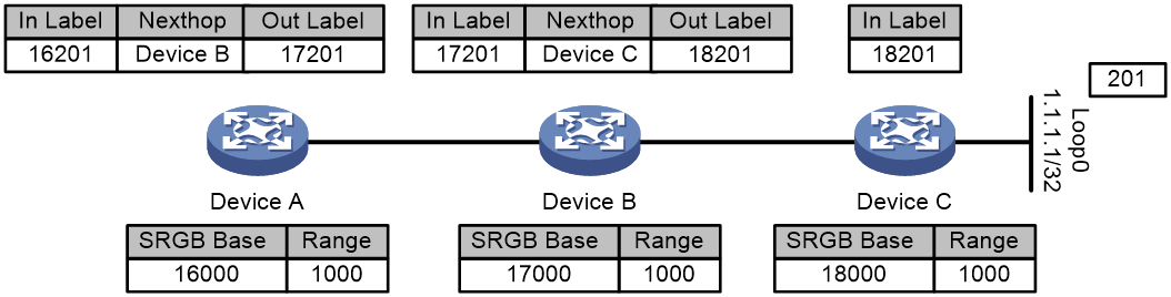
Figure 1 shows how dynamic label forwarding entries are created. After you assign index value 201 to loopback address 1.1.1.1/32 on Device C, Device C uses an IGP packet to advertise the index value and its local SRGB. Then, the devices calculate incoming and outgoing labels according to the previously mentioned label calculation rules.
· Devices C calculates its incoming label, which is 18201.
· Device B calculates its incoming label and outgoing label and creates a label forwarding entry. The incoming label is 17201. The outgoing label is 18201. The next hop is Device C.
· Device A calculates its incoming label and outgoing label and creates a label forwarding entry. The incoming label is 16201. The outgoing label is 17201. The next hop is Device B.
Label forwarding entry installation based on adjacency SIDs
When using adjacency SIDs, each device allocates a static or dynamic incoming label to the link to its neighbor. The label has local significance. Multiple devices can use the same adjacency SID.
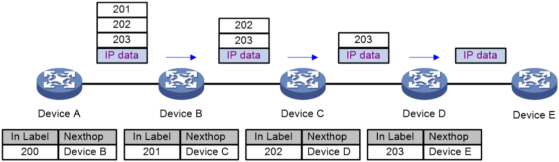
Figure 2 Creating label forwarding entries based on adjacency SIDs
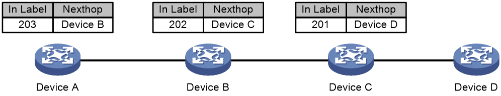
As shown in Figure 2, the devices are running the same IGP. After IGP adjacencies are established between the devices, Device A, Device B, and Device C allocates labels and creates label forwarding entries as follows:
· Device A allocates label 203 to the link to its neighbor Device B.
· Device B allocates label 202 to the link to its neighbor Device C.
· Device C allocates label 201 to the link to its neighbor Device D.
· Device A creates a label forwarding entry with incoming label 203 and next hop Device B.
· Device B creates a label forwarding entry with incoming label 202 and next hop Device C.
· Device C creates a label forwarding entry with incoming label 201 and next hop Device D.
SRLSP setup
You can use the following methods to create SRLSPs:
· Configure SR nodes to use an IGP to dynamically establish an SRLSP.
SR nodes follow these steps to establish SRLSPs:
a. Use an IGP to collect prefix SID information from the MPLS SR network.
b. Calculate the shortest paths to other SR nodes based on the collected prefix SID information and the IGP network topology.
c. Establish SRLSPs based on the shortest paths.
· Configure a controller to deploy SRLSP configuration to the device so the device creates SRLSPs.
For more information about controller configuration, see the user guide for the controller.
Packet forwarding in MPLS SR
Based on the SID allocation method, MPLS SR uses one of the following packet forwarding methods:
· Prefix SID-based packet forwarding—The ingress node encapsulates the prefix SID for the egress node to a packet. The transit nodes forward the packet based on label forwarding entries.
· Adjacency SID-based packet forwarding—The ingress node encapsulates the label stack that contains the adjacency SIDs of all links along the forwarding path to a packet. Each transit node uses the top label in the label stack to determine the next hop and pops the top label before forwarding the packet to the next hop.
· Prefix and adjacency SID-based packet forwarding—The nodes use prefix SID-based packet forwarding in combination with adjacency-based packet forwarding.
Prefix SID-based packet forwarding within the same AS
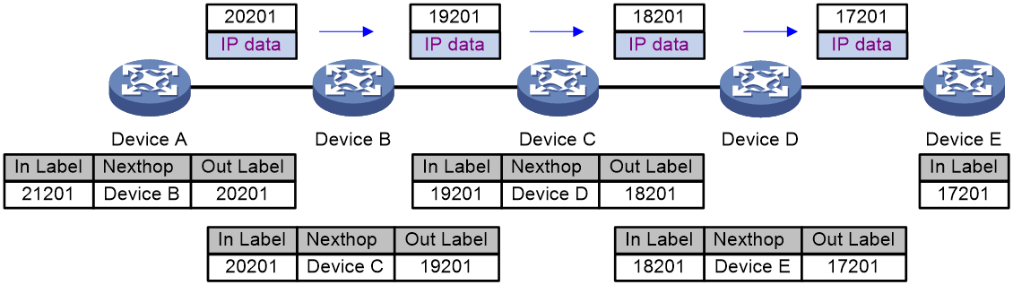
Figure 3 shows how a packet is forwarded along the SRLSP from Device A to Device E based on prefix SIDs. In this example, the outgoing label for the packet is 21201 on Device A.
1. Ingress node Device A searches for a forwarding entry for label 21201, adds outgoing label 20201 to the packet and sends the packet to the next hop (Device B).
2. When transit node Device B receives the packet, it searches for a label forwarding entry that matches the label in the packet. Then, Device B uses the outgoing label of the matched entry (19201) to replace the label in the packet and forwards the packet to the next hop (Device C).
3. Transit nodes Device C and Device D process the packet in the same way Device B does.
4. When egress node Device E receives the packet, it removes the label and forwards the packet by IP address.
Figure 3 Prefix SID-based packet forwarding within the same AS
Prefix SID-based packet forwarding across ASs
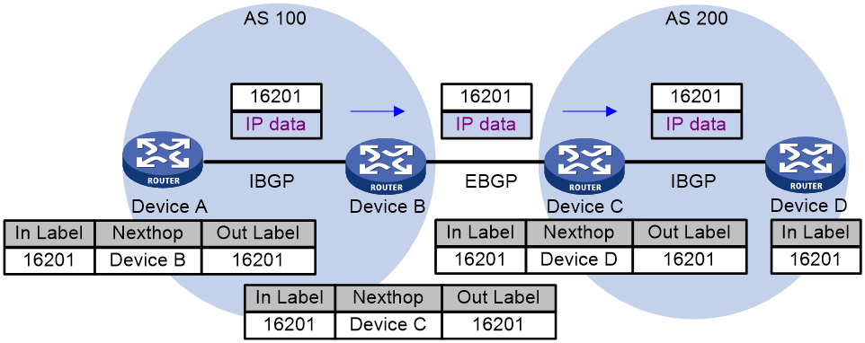
Figure 4 shows how a packet is forwarded along the SRLSP from Device A to Device D based on prefix SIDs. In this example, the outgoing label for the packet is 16201 on Device A.
1. Ingress node Device A searches for a forwarding entry for label 16201, adds outgoing label 16201 to the packet, and sends the packet to the next hop (Device B).
2. When transit node Device B receives the packet, it searches for a label forwarding entry that matches the label in the packet (16201). Then, Device B uses the outgoing label of the matched entry (16201) to replace the label in the packet and forwards the packet to the next hop (Device C).
3. Transit nodes Device C processes the packet in the same way Device B does.
4. When egress node Device D receives the packet, it removes the label and forwards the packet by IP address.
Figure 4 Prefix SID-based packet forwarding across ASs
Adjacency SID-based packet forwarding
Figure 5 shows how a packet is forwarded along the SRLSP from Device A to Device E based on adjacency SIDs. In this example, the label stack for the packet is configured as (200, 201, 202, and 203) on Device A.
1. Ingress node Device A searches for a forwarding entry for the top label (200) to determine the next hop. Then, Device A adds label stack (201, 202, and 203) to the packet, and forwards the packet to the next hop (Device B).
2. When transit node Device B receives the packet, it searches for a forwarding entry for the top label (201) to determine the next hop. Then, Device B removes the top label from the stack and forwards the packet to the next hop (Device C).
3. When transit node Device C receives the packet, it searches for a forwarding entry for the top label (202) to determine the next hop. Then, Device C removes the top label from the stack and forwards the packet to the next hop (Device D).
4. When transit node Device D receives the packet, it searches for a forwarding entry for the label (203) to determine the next hop. Then, Device D removes the label stack from the packet and forwards the packet to the next hop (Device E).
5. When egress node Device E receives the packet, it forwards the packet by IP address.
Figure 5 Adjacency SID-based packet forwarding
Prefix and adjacency SID-based packet forwarding
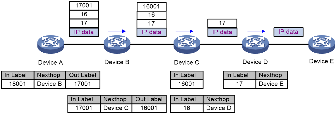
Figure 6 shows how a packet is forwarded along the SRLSP from Device A to Device E based on prefix SIDs and adjacency SIDs. In this example, the index value for the prefix SID of Device C is 1. The prefix SIDs for Device A, Device B, and Device C are 18001, 17001, and 16001, respectively. The Adjacency SIDs that Device C and Device D allocate to the adjacencies are 16 and 17, respectively. On Device A, the label stack for the packet is (18001, 16, 17).
1. Ingress node Device A searches for a forwarding entry for label 18001 to determine the outgoing label (17001) and next hop (Device B). Device A swaps label 18001 with 17001. Then, it adds label stack (17001, 16, 17) to the packet and sends the packet to the next hop (Device B).
2. When transit node Device B receives the packet, it searches for a label forwarding entry that matches the top label in the label stack (17001). Then, Device B uses the outgoing label of the matched entry (16001) to replace the top label and forwards the packet to the next hop (Device C).
3. When transit node Device C receives the packet, it removes the top label 16001 and searches for a forwarding entry for the next label (16) to determine the next hop. Then, Device C removes label 16 from the stack and forwards the packet to the next hop (Device D).
4. When transit node Device D receives the packet, it searches for a forwarding entry for the label (17) to determine the next hop. Then, Device D removes the label stack from the packet and forwards the packet to the next hop (Device E).
5. When egress node Device E receives the packet, it forwards the packet by IP address.
Figure 6 Prefix and adjacency SID-based packet forwarding
MPLS SR and LDP interworking
MPLS SR and LDP interworking enables MPLS SR networks and MPLS LDP networks to communicate and cooperate for MPLS forwarding.
MPLS SR and LDP interworking supports the following modes:
· SR to LDP—Maps prefixes on an LDP network to MPLS SR SIDs to forward traffic from an MPLS SR network to an MPLS LDP network.
· LDP to SR—Uses an IGP protocol to advertise SIDs and associates SIDs with LDP labels to forward traffic from an MPLS LDP network to an MPLS SR network.
· SR over LDP—Enables MPLS SR networks to communicate through an LDP network.
SR to LDP
The SR to LDP mode defines the following roles:
· Segment Routing Mapping Server (SRMS)—Advertises prefix-SID mappings on behalf of SR-incapable devices (LDP devices). You need to configure prefix-SID mappings on the SRMS.
· Segment Routing Mapping Client (SRMC)—Receives prefix-SID mappings advertised by the SRMS and creates MPLS SR label forwarding entries.
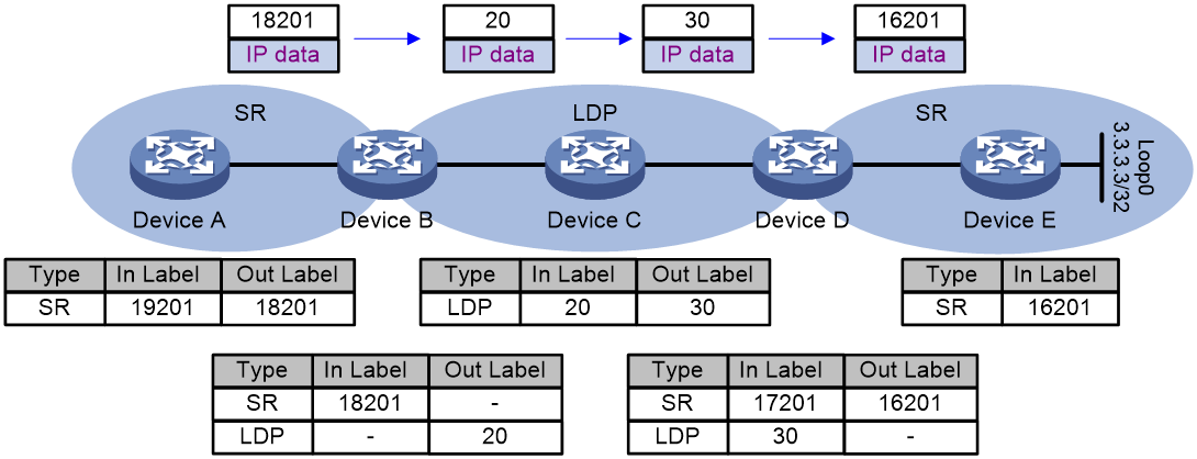
As shown in Figure 7, Device A and Device B are running MPLS SR, and Device B, Device C, and Device D are running LDP. After Device D assigns a label for destination address 3.3.3.3/32, Device B and Device C each install an LDP label forwarding entry.
The following steps establish a mapping between the SRLSP and the LDP LSP:
1. Device B acts as an SRMS. It assigns SID index value 201 to the IP address of loopback interface 0 on Device D (3.3.3.3/32), and then advertises an IP prefix-SID mapping TLV to Device A.
2. Device A acts as an SRMC. After receiving the advertised mapping TLV, it creates an MPLS SR label forwarding entry.
A mapping is established between the SRLSP and the LDP LSP.
Figure 7 SR to LDP packet forwarding
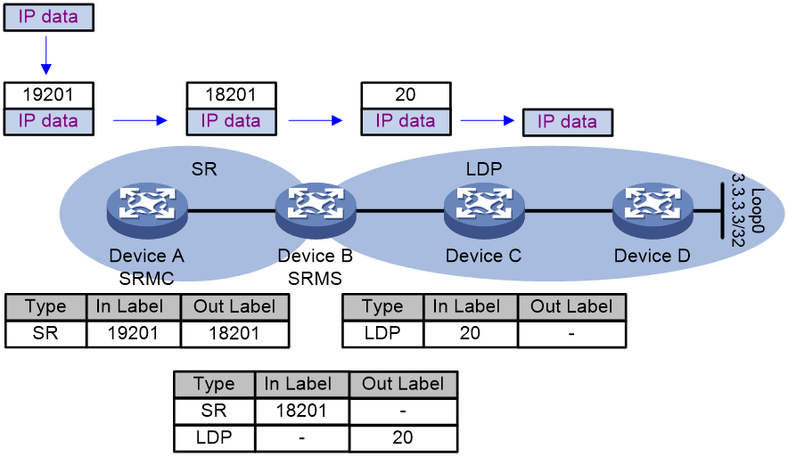
If Device A uses an SRLSP to send a packet to Device D, the packet is forwarded as follows:
1. Ingress node Device A adds label 18201 to the packet and then sends the packet to transit node Device B.
2. When transit node Device B receives the packet, it searches for a label forwarding entry that matches incoming label 18201. Because the entry does not have an outgoing label, Device B searches for a valid LDP outgoing label for destination address 3.3.3.3/32. Then, Device B adds the LDP label (20) to the packet as the SR outgoing label and forwards the packet to the next hop (Device C).
3. When transit node Device C receives the packet, it searches for an LDP label forwarding entry for incoming label 20. Then, it removes the label from the packet and forwards the packet to egress node Device D.
4. The egress node forwards the packet by IP address.
LDP to SR
As shown in Figure 8, Device C and Device D are running MPLS SR, and Device A, Device B, and Device C are running LDP. Each device running LDP assigns a label to destination address 3.3.3.3/32 and then installs an LDP label forwarding entry.
The following steps establish an association between the MPLS SR label and the LDP label:
1. After you assign SID index value 201 to the IP address of loopback interface 0 on Device D (3.3.3.3/32), Device D sends an IGP protocol packet to advertise the index value and the local SRGB.
2. After receiving the packet, Device C creates an MPLS SR label forwarding entry.
The MPLS SR label and the LDP label are associated on Device C.
Figure 8 LDP to SR packet forwarding
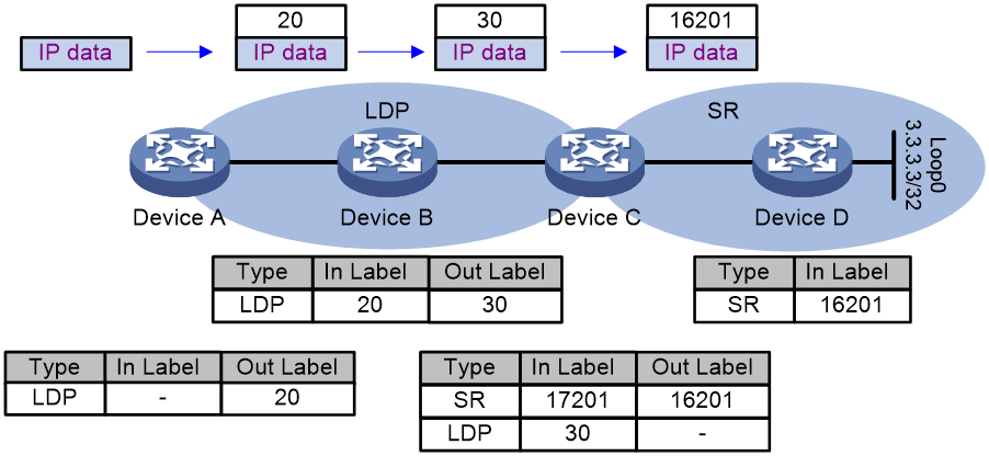
A packet from Device A to Device D is forwarded as follows:
1. Ingress node Device A adds an LDP label (20) to the packet and forwards the packets to the next hop (Device B).
2. Device B searches for an LDP label forwarding entry, uses 30 as the outgoing label, and forwards the packet to the next hop (Device C).
3. Device C searches for an LDP label forwarding entry for incoming label 30 and finds no outgoing label. Because valid MPLS SR outgoing label 16201 exists for the destination address 3.3.3.3.32, Device C uses the label (16201) as the outgoing label and forwards the packet to Device D.
4. Egress node Device D deletes label 16201 from the packet and forwards the packet by IP address.
SR over LDP
For MPLS SR networks to communicate across an LDP network, the SR/LDP border devices must be able to connect the SR LSP and the LDP LSP as follows:
· MPLS SR to LDP interwoking—The border device installs SR-to-LDP label forwarding entries. For a packet from the MPLS SR network to the LDP network, the MPLS SR label forwarding entry on the border device does not have an outgoing label. The border device uses the outgoing label of the LDP label forwarding entry for the same destination address as the outgoing label of the packet.
· LDP to MPLS SR interwoking—The border device installs LDP-to-SR label forwarding entries. For a packet from the LDP network to the MPLS SR network, the LDP forwarding entry on the border device does not have an outgoing label. The border device must use the outgoing label of the MPLS SR forwarding entry for the same destination address as the outgoing label of the packet.
As shown in Figure 9, Device A, Device B, Device D, and Device E are running MPLS SR. After you assign index value 201 to loopback interface address 3.3.3.3/32 on Device E, Device E will advertise the index value and the local SRGB. After Device A, Device B, and Device D receive the message, they will install their respective MPLS SR label forwarding entries. Device B, Device C, and Device D are running LDP. They allocate labels to destination address 3.3.3.3/32 to generate the LDP label forwarding entries.
A packet that Device A sends to Device E will be forwarded as follows:
1. Ingress node Device A encapsulates label 18201 to the packet and forwards the packet to transit node Device B.
2. Transit node Device B searches for an MPLS SR label forwarding entry for incoming label 18201 and finds that the entry does not have an outgoing label. Because an LDP label forwarding entry with outgoing label 20 exists for the destination address (3.3.3.3/32), Device B encapsulates outgoing label 20 in the packet. Then Device B sends the packet to transit node Device C.
3. Device C forwards the packet to Device D based on its LDP label forwarding entries. The outgoing label is 30.
4. Device D searches for an LDP label forwarding entry for incoming label 30 and finds that the entry does not have an outgoing label. Because an MPLS SR label forwarding entry with outgoing label 16201 exists for the destination address (3.3.3.3/32), Device B encapsulates outgoing label 16201 in the packet. Then Device D sends the packet to egress node Device E.
5. Egress node Device E deletes the incoming label and forwards the packet by IP address.
TI-LFA FRR
Topology-Independent Loop-Free Alternate Fast Re-Route (TI-LFA FRR) provides link and node protection. When a link or node fails, TI-LFA FRR switches the traffic to the backup path to ensure continuous data forwarding.
TI-LFA FRR advantages
SR-based TI-LFA FRR has the following advantages:
· It satisfies the basic requirements for IP FRR fast convergence.
· Traffic protection is not affected by the network environment.
· The algorithm is not too complicated.
· It uses the converged route as the backup path. All devices have finished route convergence before the forward process begins.
TI-LFA FRR concepts
· P space—Use the source node of the protected link as the root to establish a shortest path tree. All nodes that are reachable from the source node without passing the protected link form the P space. Nodes in the P space are called P nodes.
· Extended P space—Use the source node of the protected link and its neighbors as the roots to establish shortest path trees. All nodes that are reachable from the source node or one of its neighbors without passing the protected link form the extended P space. The P space is a subset of the extended P space.
· Q space—Use the destination node of the protected link as the root to establish a reverse shortest path tree. All nodes that are reachable from the root node without passing the protected link form the Q space. Nodes in the Q space are called Q nodes.
· TI-LFA algorithm—In real networks, the P space and Q space do not have common nodes or directly connected nodes. The device cannot calculate the backup path and cannot meet the high availability requirement. The TI-LFA algorithm can calculate the extended P space, Q space, converged shortest path tree, repair list, and backup output interface for the protected link to get the backup next hop.
· Repair list—A constraint path used to indicate how a P node reaches a Q node when the P space and Q space do not have common nodes. The repair list contains the following labels (SIDs):
¡ Labels of P nodes.
¡ Adjacency labels from P nodes to Q nodes.
TI-LFA FRR protection types
The following TI-LFA traffic protection types are available:
· Link protection—Protects traffic that traverses a specific link.
· Node protection—Protects traffic that traverses a specific node.
Node protection takes precedence over link protection.
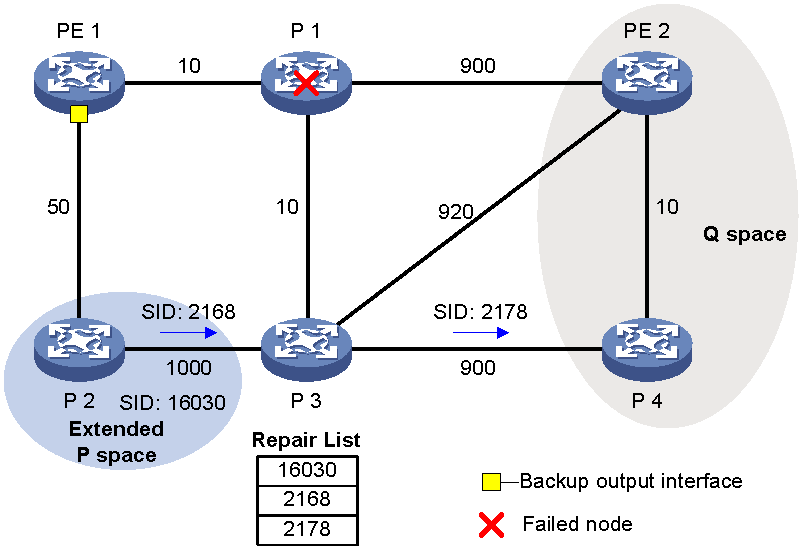
TI-LFA FRR path calculation
As shown in Figure 10, PE 1 is the source node. P 1 is the faulty node. PE 2 is the destination node. The numbers on links represent the link costs. A data flow traverses PE 1, P 1, and PE 2. To protect data against P 1 failure, TI-LFA FRR calculates the extended P space, Q space, shortest path tree converged after P 1 fails, repair list, and backup output interface, and creates the backup forwarding entry.
TI-LFA FRR calculates the backup path by using the following steps:
1. Calculates the extended P space: P 2.
2. Calculates the Q space: PE 2 and P 4.
3. Calculates the shortest path tree converged after P 1 fails: PE 1 --> P 2 --> P 4 --> PE 2.
4. Calculates the repair list: Node label of P 2 (16030), adjacency label of P 2 to P 3 (2168), and adjacency label of P 3 to P 4 (2178).
5. Calculates the backup output interface, that is, the output interface to the next hop after the link from PE 1 to P 1 fails.
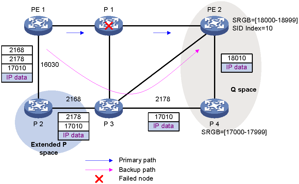
TI-LFA FRR forwarding process
After TI-LFA FRR finishes backup path calculation, traffic will be switched to the backup path in response to a primary path failure.
As shown in Figure 11, P 2 is a P node and P 4 is a Q node. When the next hop on the primary path (P 1) fails, TI-LFA FRR switches the traffic to the backup path. The following are the detailed steps:
1. PE 1 encapsulates a label stack to a packet according to the repair list. The labels, from the outmost to inmost, are as follows:
¡ Node label of P node P2 (16030), which equals the SRGB base value of P 2 plus the SID index value of P 2.
¡ Adjacency labels from P node P2 to Q node P 4, which are 2168 and 2178.
¡ The destination's node label 17010, which equals the SRGB base value of Q node P 4 plus the SID index value of destination node PE 2.
2. P2 receives the packet, searches for a label forwarding entry based on the outmost label, pops label 2168, and forwards the packet to P 3.
3. P3 receives the packet, searches for a label forwarding entry based on the outmost label, pops label 2178, and forwards the packet to P 4.
4. P4 receives the packet, and searches for a label forwarding entry based on the outmost label. Because the outgoing label is 18010 and the next hop is PE 2, P 4 encapsulates 18010 as the outmost label and forwards the packet to PE 2.
Figure 11 Data forwarding over the TI-LFA FRR backup path
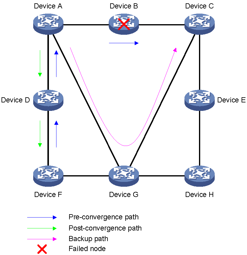
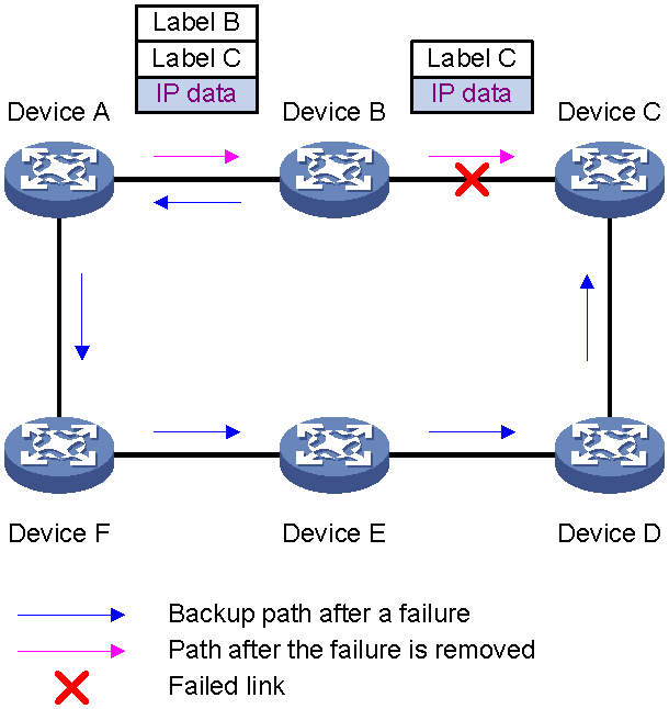
Microloop avoidance after a network failure
As shown in Figure 12, when Device B fails, traffic to Device C will be switched to the backup path calculated by TI-LFA. After Device A finishes route convergence, traffic will be switched to the post-convergence path. If Device D and Device F have not finished route convergence and still forward traffic along the pre-convergence path, a loop is formed between Device A and Device F. The loop exists until Device D and Device F finish route convergence.
FRR microloop avoidance and SR microloop avoidance can resolve this issue. After you configure TI-LFA, Device A first switches traffic to the backup path calculated by TI-LFA when Device B fails. Then, Device A waits for Device D and Device F to finish route convergence before starting route convergence. After Device A also finishes route convergence, Device A switches the traffic to the converged route.
Figure 12 Diagram for microloop avoidance after a network failure
Microloop avoidance after a failure recovery
As shown in Figure 13, before the link between Device B and Device C recovers, traffic traverses along the backup path. After the link recovers, Device A will forward the traffic to Device B if Device A finishes route convergence before Device B. Before Device B also finishes route convergence, Device B still forwards the traffic along the backup path. A loop is formed between Device A and Device B.
SR microloop avoidance can resolve this issue. After the link recovers, SR microloop avoidance automatically calculates the optimal path from Device A to Device C and forwards traffic along the path. To forward a packet along the newly calculated path, Device A adds, for example, the adjacency label from Device B to Device C to the packet and then sends the packet to Device B. Then, Device B forwards the packet to Device C based on the path information.
When the microloop avoidance RIB-update-delay timer expires, Device B should have finished route convergence. Device A does not add path information to packets anymore, and it forwards packets to Device C as usual.
Figure 13 Diagram for microloop avoidance after a failure recovery
Protocols and standards
· draft-bashandy-rtgwg-segment-routing-ti-lfa-04
· draft-ietf-spring-segment-routing-mpls-00
· draft-ietf-spring-segment-routing-02
· draft-ietf-isis-segment-routing-extensions-06
· draft-ietf-spring-segment-routing-11
MPLS SR tasks at a glance
IP traffic forwarding over SRLSPs tasks at a glance
To forward IP traffic over SRLSPs, perform the following configuration tasks:
1. Configuring segments
¡ Configuring IGP-based SID advertisement
2. (Optional.) Configuring the device to prefer SRLSPs in traffic forwarding
3. (Optional.) Configuring MPLS SR and LDP interworking
4. (Optional.) Configuring TI-LFA FRR
Configuring IGP-based SID advertisement
IGP-based prefix SID advertisement tasks at a glance
Perform the following tasks on each node along an SRLSP:
1. Configuring the IGP to support MPLS SR
Perform this task if you are configuring prefix SIDs.
IGP-based adjacency SID advertisement tasks at a glance
Perform the following tasks on each node along an SRLSP:
1. Configuring the IGP to support MPLS SR
2. Enabling MPLS SR adjacency label allocation for the IGP
The device will allocate SIDs to adjacencies randomly.
3. (Optional.) Assigning adjacency SIDs
You can assign adjacency SIDs to adjacencies manually.
Prerequisites for configuring IGP-based SID advertisement
Before you configure IGP-based SID advertisement, perform the following tasks:
· Determine the ingress node, transit nodes, and egress node of an SRLSP.
· Determine the following items for each node:
¡ Index value for the prefix SID.
¡ MPLS SRGB.
· Enable MPLS on all nodes and interfaces that will participate in MPLS forwarding. For information about enabling MPLS, see basic MPLS configuration in MPLS Configuration Guide.
Configuring the IGP to support MPLS SR
Prerequisites
For MPLS SR to take effect, set the IS-IS cost style to wide, compatible, or wide-compatible before configuring IS-IS to support MPLS SR. For more information about the cost style, see IS-IS configuration in Layer 3—IP Routing Configuration Guide.
Configuring IS-IS to support MPLS SR
1. Enter system view.
system-view
2. Enter IS-IS view.
isis process-id
3. Enter IS-IS IPv4 unicast address family view.
address-family ipv4
4. Enable MPLS SR.
segment-routing mpls
By default, MPLS SR is disabled.
Configuring prefix SIDs
About this task
Configuring a prefix SID in lookback interface view binds the SID with the IP address of the loopback interface.
To configure a prefix SID, use one of the following methods:
· Specify an absolute value in the SRGB. The absolute value is used as the prefix SID.
· Specify an index value. The sum of the index value and the SRGB base value is used as the prefix SID. The prefix SID must be in the SRGB.
Restrictions and guidelines
To use a prefix SID for a group of SR nodes in anycast scenarios, specify the n-flag-clear keyword to set the Node-SID flag bit of the prefix SID to 0.
To configure an IS-IS prefix SID, you must enable an IS-IS process on the loopback interface.
Configuring an IS-IS prefix SID
1. Enter system view.
system-view
2. Enter loopback interface view.
interface loopback interface-number
3. Configure an IS-IS prefix SID.
isis prefix-sid { absolute absolute-value | index index-value } [ n-flag-clear ] [ explicit-null ]
By default, no IS-IS prefix SID is configured.
Enabling MPLS SR adjacency label allocation for the IGP
Restrictions and guidelines
For this feature to take effect, you must enable MPLS SR.
Enabling MPLS SR adjacency label allocation for IS-IS
1. Enter system view.
system-view
2. Enter IS-IS view.
isis process-id
3. Enter IS-IS IPv4 unicast address family view.
address-family ipv4
4. Enable MPLS SR adjacency label allocation.
segment-routing adjacency enable
By default, MPLS SR adjacency label allocation is disabled.
Assigning adjacency SIDs
About this task
After you enable MPLS SR adjacency label allocation, the device randomly allocates adjacency SIDs to the links to its IGP neighbors. If the link to an IGP neighbor flaps, the adjacency SID of the link keeps changing. For a link to always use the same adjacency SID, use this feature to assign a specific adjacency SID to the link.
Restrictions and guidelines
To assign adjacency SIDs by using absolute values, make sure the SIDs are in the label range of the SRLB. To assign adjacency SIDs by using index values, make sure the index values plus the base value of the SRLB are in the label range of the SRLB.
The assigned adjacency SIDs take effect after you enable MPLS SR and MPLS SR adjacency label allocation.
Prerequisites
Before assigning adjacency SIDs, execute the display mpls label command to display the usage status of the labels that you want to assign as adjacency SIDs. Make sure the labels are in Idle state.
A label that is not in Idle state is being used by another protocol. If you assign it to a link as an adjacency SID, the adjacency SID is not available even if the status of the label changes to Idle later. To use the adjacency SID, you must remove the adjacency SID assignment and assign the adjacency SID again.
Assigning adjacency SIDs to IS-IS adjacencies
1. Enter system view.
system-view
2. Enter interface view.
interface interface-type interface-number
3. Assign an adjacency SID to an IS-IS adjacency link.
isis adjacency-sid { absolute absolute-value | index index-value } [ nexthop nexthop-address ]
By default, an IS-IS adjacency link does not have an adjacency SID.
Configuring the MPLS SRGB
Restrictions and guidelines
To configure the SRGB of a node successfully, make sure the SRGB contains the prefix SID configured for the node.
MPLS reserves labels in the range of 16000 to 24000 for SRGB. The minimum and maximum label values of the SRBG must be in the range.
Configuring the MPLS SRGB for IS-IS
1. Enter system view.
system-view
2. Enter IS-IS view.
isis process-id
3. Configure the MPLS SRGB.
segment-routing global-block minivalue maxivalue
By default, the minimum label value is 16000, and the maximum label value is 24000.
Configuring the device to prefer SRLSPs in traffic forwarding
About this task
This feature enables the device to preferentially use SRLSPs to forward traffic when both SRLSPs and LDP LSPs are available for traffic forwarding. If you do not configure this feature, the device prefers to use LDP LSPs for traffic forwarding.
Restrictions and guidelines
This feature takes effect only when MPLS SR is enabled and SRLSPs use prefix SIDs.
Configuring the device to prefer SRLSPs established by IS-IS in traffic forwarding
1. Enter system view.
system-view
2. Enter IS-IS view.
isis process-id
3. Configure the device to prefer SRLSPs in traffic forwarding.
segment-routing sr-prefer [ prefix-list prefix-list-name ]
By default, the device prefers LDP LSPs to SRLSPs.
Configuring MPLS SR and LDP interworking
Restrictions and guidelines for MPLS SR and LDP interworking
To configure MPLS SR and LDP interworking, make sure the SRLSP uses prefix SIDs.
In the current software version, the SRMS and SRMC devices support only IS-IS-based MPLS SR.
SR to LDP tasks at a glance
SRMS tasks at a glance
Perform the following tasks on an SRMS:
1. Enabling MPLS SR on the SRMS:
d. Configuring the IGP to support MPLS SR
2. Enabling advertisement of locally configured prefix-SID mappings
3. Configuring prefix-SID mappings
SRMC tasks at a glance
Perform the following tasks on each SRMC:
1. Enabling MPLS SR on the SRMC:
g. Configuring the IGP to support MPLS SR
2. Enabling reception of advertised prefix-SID mappings
LDP to SR tasks at a glance
1. Configuring the IGP to support MPLS SR
SR over LDP tasks at a glance
1. Configuring the IGP to support MPLS SR
Prerequisites for MPLS SR and LDP internetworking
Before you configure MPLS SR and LDP internetworking, perform the following tasks:
· Determine the ingress node, transit nodes, and egress node of an SRLSP.
· Determine the index value for the prefix SID of each node.
· Enable MPLS on all nodes and interfaces that will participate in MPLS forwarding. For information about enabling MPLS, see basic MPLS configuration in MPLS Configuration Guide.
Enabling advertisement of locally configured prefix-SID mappings
Restrictions and guidelines
Configure this feature on the device that acts as the SRMS.
Configuring IS-IS to advertise locally configured prefix-SID mappings
1. Enter system view.
system-view
2. Enter IS-IS view.
isis process-id
3. Enter IS-IS IPv4 unicast address family view.
address-family ipv4
4. Enable advertisement of locally configured prefix-SID mappings.
segment-routing mapping-server advertise-local
By default, advertisement is disabled for locally configured prefix-SID mappings.
Configuring prefix-SID mappings
Restrictions and guidelines
Configure this feature on the device that acts as the SRMS.
The specified prefixes must not belong to any existing prefix-SID mappings.
Prerequisites
Before you configure prefix-SID mappings in bulk, plan the number of mappings carefully.
Procedure
1. Enter system view.
system-view
2. Enable SR and enter segment routing view.
segment-routing
3. Configure a prefix-SID mapping.
mapping-server prefix-sid-map ip-address mask-length start-value [ range range-value ] [ attached ]
By default, no prefix-SID mappings exist.
If you specify a value greater than 65535 for the range-value argument, the prefix-SID mappings cannot be advertised through IS-IS or OSPF.
Enabling reception of advertised prefix-SID mappings
Restrictions and guidelines
Configure this feature on the devices that act as the SRMCs.
Configuring IS-IS to receive advertised prefix-SID mappings.
1. Enter system view.
system-view
2. Enter IS-IS view.
isis process-id
3. Enter IS-IS IPv4 unicast address family view.
address-family ipv4
4. Enable reception of prefix-SID mappings.
segment-routing mapping-server receive
By default, reception of prefix-SID mappings is enabled.
Configuring TI-LFA FRR
Restrictions and guidelines for TI-LFA FRR
TI-LFA FRR is not supported on static SR networks.
In MPLS SR and LDP interworking scenarios, you must configure the device to prefer the IS-IS SRLSP to the LDP LSP. This rule ensures the effectiveness of the TI-LFA FRR backup next hop.
TI-LFA FRR tasks at a glance
2. (Optional.) Disabling an interface from participating in TI-LFA calculation
On the source node, disable TI-LFA on the route's output interface to the next hop on the primary path.
3. (Optional.) Configuring microloop avoidance
Enabling TI-LFA FRR
Enabling TI-LFA FRR for IS-IS
1. Enter system view.
system-view
2. Enter IS-IS view.
isis process-id
3. Enter IS-IS IPv4 unicast address family view.
address-family ipv4
4. Enable LFA FRR for IS-IS.
fast-reroute lfa [ level-1 | level-2 ]
By default, LFA FRR is disabled for IS-IS.
5. Enable TI-LFA FRR for IS-IS.
fast-reroute ti-lfa [ level-1 | level-2 ]
By default, TI-LFA FRR is disabled for IS-IS.
Disabling an interface from participating in TI-LFA calculation
1. Enter system view.
system-view
2. Enter the view of IS-IS interface.
interface interface-type interface-number
3. Disable the interface from participating in TI-LFA calculation.
isis fast-reroute ti-lfa disable [ per-prefix ] [ route-policy route-policy-name | host ] [ level-1 | level-2 ]
By default, an IS-IS interface participates in TI-LFA calculation.
Configuring microloop avoidance
About this task
The following microloop avoidance methods are available:
· FRR microloop avoidance—Provides microloop avoidance after a network failure.
On a network deployed with TI-LFA FRR, when a node or link fails, traffic will be switched to the backup path calculated by TI-LFA. If devices on the backup path have not finished route convergence, a loop is formed between the source node (failed node or the previous node along the link) and a device on the backup path. The loop exists until the devices on the backup path finish route convergence.
To resolve this issue, FRR microloop avoidance first switches traffic to the backup path calculated by TI-LFA after the node or link failure. Then, the source node waits for the nodes on the backup path to finish route convergence before starting route convergence.
· SR microloop avoidance—Provides microloop avoidance both after a network failure and after a failure recovery.
After a network failure occurs or recovers, route convergence occurs on relevant network devices. Because of non-simultaneous convergence on network devices, microloops might be formed. After you configure SR microloop avoidance, the devices will forward traffic along the specified path before route convergence is finished on all the relevant network devices. Because the forwarding path is independent of route convergence, microloops are avoided.
To leave sufficient time for IGP to finish route convergence, set the SR microloop avoidance RIB-update-delay timer. Before the timer expires, failure relevant devices will forward traffic along the specified path. After the timer expires, IGP route convergence should have finished and traffic will traverse along the IGP-calculated path.
Restrictions and guidelines
If you configure both FRR microloop avoidance and SR microloop avoidance, SR microloop avoidance takes effect.
Configuring FRR microloop avoidance for IS-IS
1. Enter system view.
system-view
2. Enter IS-IS view.
isis process-id
3. Enter IS-IS IPv4 unicast address family view.
address-family ipv4
4. Enable FRR microloop avoidance for IS-IS.
fast-reroute microloop-avoidance enable [ level-1 | level-2 ]
By default, FRR microloop avoidance is disabled for IS-IS.
5. (Optional.) Set the FRR microloop avoidance RIB-update-delay time.
fast-reroute microloop-avoidance rib-update-delay delay-time [ level-1 | level-2 ]
By default, the FRR microloop avoidance RIB-update-delay time is 5000 ms.
Configuring SR microloop avoidance for IS-IS
1. Enter system view.
system-view
2. Enter IS-IS view.
isis process-id
3. Enter IS-IS IPv4 unicast address family view.
address-family ipv4
4. Enable SR microloop avoidance for IS-IS.
segment-routing microloop-avoidance enable [ level-1 | level-2 ]
By default, SR microloop avoidance is disabled for IS-IS.
5. (Optional.) Set the SR microloop avoidance RIB-update-delay time.
segment-routing microloop-avoidance rib-update-delay delay-time [ level-1 | level-2 ]
By default, the SR microloop avoidance RIB-update-delay time is 5000 ms.
Display and maintenance commands for MPLS SR
Execute display commands in any view.
|
Task |
Command |
|
Display IS-IS SR adjacency segment information. |
display isis segment-routing adjacency [ process-id ] |
|
Display IS-IS SRGB information. |
display isis segment-routing global-block [ level-1 | level-2 ] [ process-id ] |
|
Display IS-IS SR prefix-SID mappings. |
display isis segment-routing prefix-sid-map [ active-policy | backup-policy ] [ process-id ] [ verbose ] |
|
Display prefix-SID mappings. |
display segment-routing mapping-server prefix-sid-map [ ip-address mask-length | verbose ] |
MPLS SR configuration examples
Network configuration
As shown in Figure 14, complete the following tasks:
· Start IS-IS and enable IS-IS-based MPLS SR on the PEs in the same AS.
· Configure PE 1 and ASBR-PE 1 to exchange labeled IPv4 routes through IBGP. Enable BGP-based MPLS SR.
· Configure PE 2 and ASBR-PE 2 to exchange labeled IPv4 routes through IBGP. Enable BGP-based MPLS SR.
· Establish an MP-EBGP peer relationship between PE 1 and PE 2 to exchange VPNv4 routes.
· Configure ASBR-PE 1 and ASBR-PE 2 to exchange labeled IPv4 routes through EBGP. Enable BGP-based MPLS SR.
· Configure dynamic SID allocation on loopback interfaces of the devices. Then, establish an SRLSP based on the allocated SIDs and configure an MPLS TE tunnel over the SRLSP to transmit data.
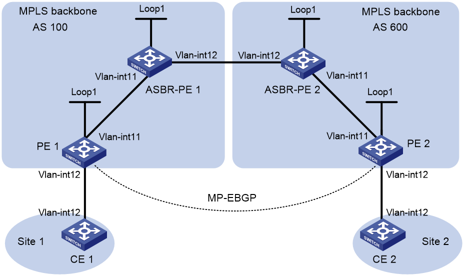
Table 1 Interface and IP address assignment
|
Device |
Interface |
IP address |
Device |
Interface |
IP address |
|
PE 1 |
Loop1 |
2.2.2.9/32 |
PE 2 |
Loop1 |
5.5.5.9/32 |
|
|
Vlan-int11 |
1.1.1.2/8 |
|
Vlan-int11 |
9.1.1.2/8 |
|
|
Vlan-int12 |
30.0.0.1/24 |
|
Vlan-int12 |
20.0.0.1/24 |
|
ASBR-PE 1 |
Loop1 |
3.3.3.9/32 |
ASBR-PE 2 |
Loop1 |
4.4.4.9/32 |
|
|
Vlan-int11 |
1.1.1.1/8 |
|
Vlan-int11 |
9.1.1.1/8 |
|
|
Vlan-int12 |
11.0.0.2/8 |
|
Vlan-int12 |
11.0.0.1/8 |
|
CE 1 |
Vlan-int12 |
30.0.0.2/24 |
CE 2 |
Vlan-int12 |
20.0.0.2/24 |
Procedure
1. Configure IP addresses and masks for interfaces. (Details not shown.)
2. Configure CE 1:
# Assign an IP address to interface VLAN-interface 12.
<CE1> system-view
[CE1] interface vlan-interface 12
[CE1-Vlan-interface12] ip address 30.0.0.2 24
[CE1-Vlan-interface12] quit
# Establish an EBGP peer relationship with PE 1, and redistribute VPN routes.
[CE1] bgp 65001
[CE1-bgp-default] peer 30.0.0.1 as-number 100
[CE1-bgp-default] address-family ipv4 unicast
[CE1-bgp-default-ipv4] peer 30.0.0.1 enable
[CE1-bgp-default-ipv4] import-route direct
3. Configure PE 1:
# Start IS-IS on PE 1, set the LSR ID, and enable MPLS and MPLS TE.
<PE1> system-view
[PE1] isis 1
[PE1-isis-1] network-entity 00.0000.0000.0001.00
[PE1-isis-1] cost-style wide
[PE1-isis-1] quit
[PE1] mpls lsr-id 2.2.2.9
[PE1] mpls te
[PE1-te] quit
[PE1] interface vlan-interface 11
[PE1-Vlan-interface11] isis enable 1
[PE1-Vlan-interface11] mpls enable
[PE1-Vlan-interface11] quit
[PE1] interface vlan-interface 12
[PE1-Vlan-interface12] mpls enable
[PE1-Vlan-interface12] quit
[PE1] interface loopback 1
[PE1-LoopBack1] ip address 2.2.2.9 32
[PE1-LoopBack1] isis enable 1
[PE1-LoopBack1] quit
# Enable MPLS SR in IS-IS IPv4 unicast address family view and configure an IS-IS prefix SID.
[PE1] isis 1
[PE1-isis-1] address-family ipv4
[PE1-isis-1-ipv4] segment-routing mpls
[PE1-isis-1-ipv4] quit
[PE1-isis-1] quit
[PE1] interface loopback 1
[PE1-LoopBack1] isis prefix-sid index 20
[PE1-LoopBack1] quit
# Create VPN instance vpn1, and configure the RD and route target attributes.
[PE1] ip vpn-instance vpn1
[PE1-vpn-instance-vpn1] route-distinguisher 11:11
[PE1-vpn-instance-vpn1] vpn-target 1:1 2:2 3:3 import-extcommunity
[PE1-vpn-instance-vpn1] vpn-target 3:3 export-extcommunity
[PE1-vpn-instance-vpn1] quit
# Associate VLAN-interface 12 with VPN instance vpn1, and assign an IP address to the interface.
[PE1] interface vlan-interface 12
[PE1-Vlan-interface12] ip binding vpn-instance vpn1
[PE1-Vlan-interface12] ip address 30.0.0.1 24
[PE1-Vlan-interface12] quit
# Create a routing policy and specify a label index value.
[PE1] route-policy policy1 permit node 1
[PE1-route-policy-policy1-1] apply label-index 10
[PE1-route-policy-policy1-1] quit
# Start BGP on PE 1. Enable the capability to exchange labeled routes with IBGP peer 3.3.3.9.
[PE1] bgp 100
[PE1-bgp-default] peer 3.3.3.9 as-number 100
[PE1-bgp-default] peer 3.3.3.9 connect-interface loopback 1
[PE1-bgp-default] address-family ipv4 unicast
[PE1-bgp-default-ipv4] peer 3.3.3.9 enable
[PE1-bgp-default-ipv4] peer 3.3.3.9 label-route-capability
# Enable MPLS SR.
[PE1-bgp-default-ipv4] segment-routing mpls
# Redistribute the route of loopback interface 1 to BGP and apply the routing policy.
[PE1-bgp-default-ipv4] network 2.2.2.9 32 route-policy policy1
[PE1-bgp-default-ipv4] quit
# Configure the maximum number of hops from PE 1 to EBGP peer 5.5.5.9 as 10.
[PE1-bgp-default] peer 5.5.5.9 as-number 600
[PE1-bgp-default] peer 5.5.5.9 connect-interface loopback 1
[PE1-bgp-default] peer 5.5.5.9 ebgp-max-hop 10
# Configure peer 5.5.5.9 as a VPNv4 peer.
[PE1-bgp-default] address-family vpnv4
[PE1-bgp-default-vpnv4] peer 5.5.5.9 enable
[PE1-bgp-default-vpnv4] quit
# Configure CE 1 as an EBGP peer of PE 1 and install the learned BGP routes in the routing table of the VPN instance.
[PE1-bgp-default] ip vpn-instance vpn1
[PE1-bgp-default-vpn1] peer 30.0.0.2 as-number 65001
[PE1-bgp-default-vpn1] address-family ipv4 unicast
[PE1-bgp-default-ipv4-vpn1] peer 30.0.0.2 enable
4. Configure ASBR-PE 1:
# Start IS-IS on ASBR-PE 1, set the LSR ID, and enable MPLS and MPLS TE.
<ASBR-PE1> system-view
[ASBR-PE1] isis 1
[ASBR-PE1-isis-1] network-entity 00.0000.0000.0002.00
[ASBR-PE1-isis-1] cost-style wide
[ASBR-PE1-isis-1] quit
[ASBR-PE1] mpls lsr-id 3.3.3.9
[ASBR-PE1] mpls te
[ASBR-PE1-te] quit
[ASBR-PE1] interface vlan-interface 11
[ASBR-PE1-Vlan-interface11] isis enable 1
[ASBR-PE1-Vlan-interface11] mpls enable
[ASBR-PE1-Vlan-interface11] quit
[ASBR-PE1] interface vlan-interface 12
[ASBR-PE1-Vlan-interface12] mpls enable
[ASBR-PE1-Vlan-interface12] quit
[ASBR-PE1] interface loopback 1
[ASBR-PE1-LoopBack1] ip address 3.3.3.9 32
[ASBR-PE1-LoopBack1] isis enable 1
[ASBR-PE1-LoopBack1] quit
# Enable MPLS SR in IS-IS IPv4 unicast address family view and configure an IS-IS prefix SID.
[ASBR-PE1] isis 1
[ASBR-PE1-isis-1] address-family ipv4
[ASBR-PE1-isis-1-ipv4] segment-routing mpls
[ASBR-PE1-isis-1-ipv4] quit
[ASBR-PE1-isis-1] quit
[ASBR-PE1] interface loopback 1
[ASBR-PE1-LoopBack1] isis prefix-sid index 30
[ASBR-PE1-LoopBack1] quit
# Start BGP on ASBR-PE 1. Enable the capability to exchange labeled routes with IBGP peer 2.2.2.9.
[ASBR-PE1] bgp 100
[ASBR-PE1-bgp-default] peer 2.2.2.9 as-number 100
[ASBR-PE1-bgp-default] peer 2.2.2.9 connect-interface loopback 1
[ASBR-PE1-bgp-default] address-family ipv4 unicast
[ASBR-PE1-bgp-default-ipv4] peer 2.2.2.9 enable
[ASBR-PE1-bgp-default-ipv4] peer 2.2.2.9 label-route-capability
# Enable MPLS SR.
[ASBR-PE1-bgp-default-ipv4] segment-routing mpls
[ASBR-PE1-bgp-default-ipv4] quit
# Enable the capability to exchange labeled routes with EBGP peer 11.0.0.1.
[ASBR-PE1-bgp-default] peer 11.0.0.1 as-number 600
[ASBR-PE1-bgp-default] address-family ipv4 unicast
[ASBR-PE1-bgp-default-ipv4] peer 11.0.0.1 enable
[ASBR-PE1-bgp-default-ipv4] peer 11.0.0.1 label-route-capability
[ASBR-PE1-bgp-default-ipv4] quit
[ASBR-PE1-bgp-default] quit
5. Configure ASBR-PE 2:
# Start IS-IS on ASBR-PE 2, set the LSR ID, and enable MPLS and MPLS TE.
<ASBR-PE2> system-view
[ASBR-PE2] isis 1
[ASBR-PE2-isis-1] network-entity 00.0000.0000.0003.00
[ASBR-PE2-isis-1] cost-style wide
[ASBR-PE2-isis-1] quit
[ASBR-PE2] mpls lsr-id 4.4.4.9
[ASBR-PE2] mpls te
[ASBR-PE2-te] quit
[ASBR-PE2] interface vlan-interface 11
[ASBR-PE2-Vlan-interface11] isis enable 1
[ASBR-PE2-Vlan-interface11] mpls enable
[ASBR-PE2-Vlan-interface11] quit
[ASBR-PE2] interface vlan-interface 12
[ASBR-PE2-Vlan-interface12] mpls enable
[ASBR-PE2-Vlan-interface12] quit
[ASBR-PE2] interface loopback 1
[ASBR-PE2-LoopBack1] ip address 4.4.4.9 32
[ASBR-PE2-LoopBack1] isis enable 1
[ASBR-PE2-LoopBack1] quit
# Enable MPLS SR in IS-IS IPv4 unicast address family view and configure an IS-IS prefix SID.
[ASBR-PE2] isis 1
[ASBR-PE2-isis-1] address-family ipv4
[ASBR-PE2-isis-1-ipv4] segment-routing mpls
[ASBR-PE2-isis-1-ipv4] quit
[ASBR-PE2-isis-1] quit
[ASBR-PE2] interface loopback 1
[ASBR-PE2-LoopBack1] isis prefix-sid index 40
[ASBR-PE2-LoopBack1] quit
# Start BGP on ASBR-PE 2. Enable the capability to exchange labeled routes with IBGP peer 5.5.5.9.
[ASBR-PE2] bgp 600
[ASBR-PE2-bgp-default] peer 5.5.5.9 as-number 600
[ASBR-PE2-bgp-default] peer 5.5.5.9 connect-interface loopback 1
[ASBR-PE2-bgp-default] address-family ipv4 unicast
[ASBR-PE2-bgp-default-ipv4] peer 5.5.5.9 enable
[ASBR-PE2-bgp-default-ipv4] peer 5.5.5.9 label-route-capability
# Enable MPLS SR.
[ASBR-PE2-bgp-default-ipv4] segment-routing mpls
[ASBR-PE2-bgp-default-ipv4] quit
# Enable the capability to exchange labeled routes with EBGP peer 11.0.0.2.
[ASBR-PE2-bgp-default] peer 11.0.0.2 as-number 100
[ASBR-PE2-bgp-default] address-family ipv4 unicast
[ASBR-PE2-bgp-default-ipv4] peer 11.0.0.2 enable
[ASBR-PE2-bgp-default-ipv4] peer 11.0.0.2 label-route-capability
[ASBR-PE2-bgp-default-ipv4] quit
[ASBR-PE2-bgp-default] quit
6. Configure PE 2:
# Start IS-IS on PE 2, set the LSR ID, and enable MPLS and MPLS TE.
<PE2> system-view
[PE2] isis 1
[PE2-isis-1] network-entity 00.0000.0000.0004.00
[PE2-isis-1] cost-style wide
[PE2-isis-1] quit
[PE2] mpls lsr-id 5.5.5.9
[PE2] mpls te
[PE2-te] quit
[PE2] interface vlan-interface 11
[PE2-Vlan-interface11] isis enable 1
[PE2-Vlan-interface11] mpls enable
[PE2-Vlan-interface11] quit
[PE2] interface vlan-interface 12
[PE2-Vlan-interface12] mpls enable
[PE2-Vlan-interface12] quit
[PE2] interface loopback 1
[PE2-LoopBack1] ip address 5.5.5.9 32
[PE2-LoopBack1] isis enable 1
[PE2-LoopBack1] quit
# Enable MPLS SR in IS-IS IPv4 unicast address family view and configure an IS-IS prefix SID.
[PE2] isis 1
[PE2-isis-1] address-family ipv4
[PE2-isis-1-ipv4] segment-routing mpls
[PE2-isis-1-ipv4] quit
[PE2-isis-1] quit
[PE2] interface loopback 1
[PE2-LoopBack1] isis prefix-sid index 50
[PE2-LoopBack1] quit
# Create VPN instance vpn1, and configure the RD and route target attributes.
[PE2] ip vpn-instance vpn1
[PE2-vpn-instance-vpn1] route-distinguisher 11:11
[PE2-vpn-instance-vpn1] vpn-target 1:1 2:2 3:3 import-extcommunity
[PE2-vpn-instance-vpn1] vpn-target 3:3 export-extcommunity
[PE2-vpn-instance-vpn1] quit
# Associate VLAN-interface 12 with VPN instance vpn1, and assign an IP address to the interface.
[PE2] interface vlan-interface 12
[PE2-Vlan-interface12] ip binding vpn-instance vpn1
[PE2-Vlan-interface12] ip address 20.0.0.1 24
[PE2-Vlan-interface12] quit
# Create a routing policy and specify a label index value.
[PE2] route-policy policy1 permit node 1
[PE2-route-policy-policy1-1] apply label-index 50
[PE2-route-policy-policy1-1] quit
# Start BGP on PE 2. Enable the capability to exchange labeled routes with IBGP peer 4.4.4.9.
[PE2] bgp 600
[PE2-bgp-default] peer 4.4.4.9 as-number 600
[PE2-bgp-default] peer 4.4.4.9 connect-interface loopback 1
[PE2-bgp-default] address-family ipv4 unicast
[PE2-bgp-default-ipv4] peer 4.4.4.9 enable
[PE2-bgp-default-ipv4] peer 4.4.4.9 label-route-capability
# Enable MPLS SR.
[PE2-bgp-default-ipv4] segment-routing mpls
# Redistribute the route of loopback interface 1 to BGP and apply the routing policy.
[PE2-bgp-default-ipv4] network 5.5.5.9 32 route-policy policy1
[PE2-bgp-default-ipv4] quit
# Configure the maximum number of hops from PE 2 to EBGP peer 2.2.2.9 as 10.
[PE2-bgp-default] peer 2.2.2.9 as-number 100
[PE2-bgp-default] peer 2.2.2.9 connect-interface loopback 1
[PE2-bgp-default] peer 2.2.2.9 ebgp-max-hop 10
# Configure peer 2.2.2.9 as a VPNv4 peer.
[PE2-bgp-default] address-family vpnv4
[PE2-bgp-default-vpnv4] peer 2.2.2.9 enable
[PE2-bgp-default-vpnv4] quit
# Configure CE 2 as an EBGP peer of PE 2 and install the learned BGP routes in the routing table of the VPN instance.
[PE2-bgp-default] ip vpn-instance vpn1
[PE2-bgp-default-vpn1] peer 20.0.0.2 as-number 65001
[PE2-bgp-default-vpn1] address-family ipv4 unicast
[PE2-bgp-default-ipv4-vpn1] peer 20.0.0.2 enable
7. Configure CE 2:
# Assign an IP address to interface VLAN-interface 12.
<CE2> system-view
[CE2] interface vlan-interface 12
[CE2-Vlan-interface12] ip address 20.0.0.2 24
[CE2-Vlan-interface12] quit
# Establish an EBGP peer relationship with PE 2, and redistribute VPN routes.
[CE2] bgp 65002
[CE2-bgp-default] peer 20.0.0.1 as-number 600
[CE2-bgp-default] address-family ipv4 unicast
[CE2-bgp-default-ipv4] peer 20.0.0.1 enable
[CE2-bgp-default-ipv4] import-route direct
[CE2-bgp-default-ipv4] quit
[CE2-bgp-default] quit
Verifying the configuration
# Execute the display ip routing-table command on CE 1 and CE 2 to verify that they have a route to each other. (Details not shown.)
# Verify that CE 1 and CE 2 can ping each other. (Details not shown.)
# Display MPLS LSP information on PE1.
[PE1]display mpls lsp
FEC Proto In/Out Label Out Inter/NHLFE/LSINDEX
2.2.2.9/32 BGP 3/- -
5.5.5.9/32 BGP -/16040 NHLFE17
5.5.5.9 BGP -/- Vlan11
1.1.1.1 Local -/- Vlan11
2.2.2.9/32 ISIS 16020/- -
3.3.3.9/32 ISIS 16030/3 Vlan11
3.3.3.9/32 ISIS -/3 Vlan11
Example: Configuring MPLS SR to LDP (IS-IS)
Network configuration
As shown in Figure 15, complete the following tasks so Switch A and Switch C can communicate with each other:
· Configure Switch A, Switch B, and Switch C to run IS-IS.
· Configure Switch A and Switch B to run MPLS SR and establish an SRLSP between Switch A and Switch B.
· Configure Switch B and Switch C to run LDP to establish a dynamic LSP between Switch B and Switch C.
· Configure Switch B as the SRMS, map the prefix address of the LDP network to an SID, and advertise the mapping to Switch A.

Table 2 Interface and IP address assignment
|
Device |
Interface |
IP address |
Device |
Interface |
IP address |
|
Switch A |
Loop1 |
1.1.1.1/32 |
Switch B |
Loop1 |
2.2.2.2/32 |
|
|
Vlan-Int100 |
10.0.0.1/24 |
|
Vlan-Int100 |
10.0.0.2/24 |
|
Switch C |
Loop1 |
3.3.3.3/32 |
|
Vlan-Int200 |
11.0.0.1/24 |
|
|
Vlan-Int100 |
11.0.0.2/24 |
|
|
|
Procedure
1. Configure IP addresses and masks for interfaces. (Details not shown.)
2. Configure IS-IS on the switches to achieve network level connectivity and set the IS-IS cost style to wide:
# Configure Switch A.
<SwitchA> system-view
[SwitchA] isis 1
[SwitchA-isis-1] network-entity 00.0000.0000.0001.00
[SwitchA-isis-1] cost-style wide
[SwitchA-isis-1] quit
[SwitchA] interface vlan-interface 100
[SwitchA-Vlan-interface100] isis enable 1
[SwitchA-Vlan-interface100] quit
[SwitchA] interface loopback 1
[SwitchA-LoopBack1] isis enable 1
[SwitchA-LoopBack1] quit
# Configure Switch B.
<SwitchB> system-view
[SwitchB] isis 1
[SwitchB-isis-1] network-entity 00.0000.0000.0002.00
[SwitchB-isis-1] cost-style wide
[SwitchB-isis-1] quit
[SwitchB] interface vlan-interface 100
[SwitchB-Vlan-interface100] isis enable 1
[SwitchB-Vlan-interface100] quit
[SwitchB] interface vlan-interface 200
[SwitchB-Vlan-interface200] isis enable 1
[SwitchB-Vlan-interface200] quit
[SwitchB] interface loopback 1
[SwitchB-LoopBack1] isis enable 1
[SwitchB-LoopBack1] quit
# Configure Switch C.
<SwitchC> system-view
[SwitchC] isis 1
[SwitchC-isis-1] network-entity 00.0000.0000.0003.00
[SwitchC-isis-1] cost-style wide
[SwitchC-isis-1] quit
[SwitchC] interface vlan-interface 100
[SwitchC-Vlan-interface100] isis enable 1
[SwitchC-Vlan-interface100] quit
[SwitchC] interface loopback 1
[SwitchC-LoopBack1] isis enable 1
[SwitchC-LoopBack1] quit
3. Configure LSR IDs on the switches:
# Configure Switch A.
[SwitchA] mpls lsr-id 1.1.1.1
# Configure Switch B.
[SwitchB] mpls lsr-id 2.2.2.2
# Configure Switch C.
[SwitchC] mpls lsr-id 3.3.3.3
4. Configure LDP on Switch B and Switch C:
# Configure Switch B.
[SwitchB] mpls ldp
[SwitchB-ldp] quit
[SwitchB] interface vlan-interface 200
[SwitchB-Vlan-interface200] mpls enable
[SwitchB-Vlan-interface200] mpls ldp enable
[SwitchB-Vlan-interface200] quit
# Configure Switch C.
[SwitchC] mpls ldp
[SwitchC-ldp] quit
[SwitchC] interface vlan-interface 100
[SwitchC-Vlan-interface100] mpls enable
[SwitchC-Vlan-interface100] mpls ldp enable
[SwitchC-Vlan-interface100] quit
5. Enable MPLS SR on Switch A and Switch B:
# Configure Switch A.
[SwitchA] isis 1
[SwitchA-isis-1] address-family ipv4
[SwitchA-isis-1-ipv4] segment-routing mpls
[SwitchA-isis-1-ipv4] quit
# Configure Switch B.
[SwitchB] isis 1
[SwitchB-isis-1] address-family ipv4
[SwitchB-isis-1-ipv4] segment-routing mpls
[SwitchB-isis-1-ipv4] quit
6. Configure SRGBs on Switch A and Switch B:
# Configure Switch A.
[SwitchA-isis-1] segment-routing global-block 16000 16999
[SwitchA-isis-1] quit
# Configure Switch B.
[SwitchB-isis-1] segment-routing global-block 17000 17999
[SwitchB-isis-1] quit
7. Configure the SRMS:
# On Switch B, configure the IGP to advertise locally configured prefix-SID mappings.
[SwitchB] isis 1
[SwitchB-isis-1] address-family ipv4
[SwitchB-isis-1-ipv4] segment-routing mapping-server advertise-local
[SwitchB-isis-1-ipv4] quit
[SwitchB-isis-1] quit
# On Switch B, configure a prefix-SID mapping.
[SwitchB] segment-routing
[SwitchB-segment-routing] mapping-server prefix-sid-map 3.3.3.3 32 100
[SwitchB-segment-routing] quit
Verifying the configuration
# Display IS-IS SRLSP information on Switch A.
[SwitchA] display mpls lsp protocol isis
FEC Proto In/Out Label Out Inter/NHLFE/LSINDEX
3.3.3.3/32 ISIS 16100/17100 Vlan100
3.3.3.3/32 ISIS -/17100 Vlan100
The output shows that the outgoing label of the IS-IS SRLSP entry for Switch C is using the SID assigned to Switch C.
Example: Configuring MPLS SR over LDP
Network configuration
As shown in Figure 16, complete the following tasks so the two SR networks can communicate across the LDP network:
· Configure Switch A, Switch B, Switch C, Switch D, and Switch E to run IS-IS.
· Configure Switch B, Switch C, and Switch D to run LDP.
· Configure Switch A, Switch B, Switch D, and Switch E to run MPLS SR.
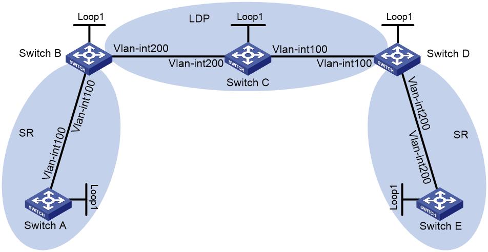
Table 3 Interface and IP address assignment
|
Device |
Interface |
IP address |
Device |
Interface |
IP address |
|
Switch A |
Loop1 |
1.1.1.1/32 |
Switch B |
Loop1 |
2.2.2.2/32 |
|
|
Vlan-Int100 |
10.0.0.1/24 |
|
Vlan-Int100 |
10.0.0.2/24 |
|
Switch C |
Loop1 |
3.3.3.3/32 |
|
Vlan-Int200 |
11.0.0.1/24 |
|
|
Vlan-Int100 |
12.0.0.1/24 |
Switch D |
Loop1 |
4.4.4.4/32 |
|
|
Vlan-Int200 |
11.0.0.2/24 |
|
Vlan-Int100 |
12.0.0.2/24 |
|
Switch E |
Loop1 |
5.5.5.5/32 |
|
Vlan-Int200 |
13.0.0.1/24 |
|
|
Vlan-Int200 |
13.0.0.2/24 |
|
|
|
Procedure
1. Configure IP addresses and masks for interfaces. (Details not shown.)
2. Configure IS-IS on the switches to achieve network level connectivity and set the IS-IS cost style to wide:
# Configure Switch A.
<SwitchA> system-view
[SwitchA] isis 1
[SwitchA-isis-1] network-entity 00.0000.0000.0001.00
[SwitchA-isis-1] cost-style wide
[SwitchA-isis-1] quit
[SwitchA] interface vlan-interface 100
[SwitchA-Vlan-interface100] isis enable 1
[SwitchA-Vlan-interface100] quit
[SwitchA] interface loopback 1
[SwitchA-LoopBack1] isis enable 1
[SwitchA-LoopBack1] quit
# Configure Switch B.
<SwitchB> system-view
[SwitchB] isis 1
[SwitchB-isis-1] network-entity 00.0000.0000.0002.00
[SwitchB-isis-1] cost-style wide
[SwitchB-isis-1] quit
[SwitchB] interface vlan-interface 100
[SwitchB-Vlan-interface100] isis enable 1
[SwitchB-Vlan-interface100] quit
[SwitchB] interface vlan-interface 200
[SwitchB-Vlan-interface200] isis enable 1
[SwitchB-Vlan-interface200] quit
[SwitchB] interface loopback 1
[SwitchB-LoopBack1] isis enable 1
[SwitchB-LoopBack1] quit
# Configure Switch C.
<SwitchC> system-view
[SwitchC] isis 1
[SwitchC-isis-1] network-entity 00.0000.0000.0003.00
[SwitchC-isis-1] cost-style wide
[SwitchC-isis-1] quit
[SwitchC] interface vlan-interface 100
[SwitchC-Vlan-interface100] isis enable 1
[SwitchC-Vlan-interface100] quit
[SwitchC] interface vlan-interface 200
[SwitchC-Vlan-interface200] isis enable 1
[SwitchC-Vlan-interface200] quit
[SwitchC] interface loopback 1
[SwitchC-LoopBack1] isis enable 1
[SwitchC-LoopBack1] quit
# Configure Switch D.
<SwitchD> system-view
[SwitchD] isis 1
[SwitchD-isis-1] network-entity 00.0000.0000.0004.00
[SwitchD-isis-1] cost-style wide
[SwitchD-isis-1] quit
[SwitchD] interface vlan-interface 100
[SwitchD-Vlan-interface100] isis enable 1
[SwitchD-Vlan-interface100] quit
[SwitchD] interface vlan-interface 200
[SwitchD-Vlan-interface200] isis enable 1
[SwitchD-Vlan-interface200] quit
[SwitchD] interface loopback 1
[SwitchD-LoopBack1] isis enable 1
[SwitchD-LoopBack1] quit
# Configure Switch E.
<SwitchE> system-view
[SwitchE] isis 1
[SwitchE-isis-1] network-entity 00.0000.0000.0005.00
[SwitchE-isis-1] cost-style wide
[SwitchE-isis-1] quit
[SwitchE] interface vlan-interface 200
[SwitchE-Vlan-interface200] isis enable 1
[SwitchE-Vlan-interface200] quit
[SwitchE] interface loopback 1
[SwitchE-LoopBack1] isis enable 1
[SwitchE-LoopBack1] quit
3. Configure LSR IDs on the switches:
# Configure Switch A.
[SwitchA] mpls lsr-id 1.1.1.1
# Configure Switch B.
[SwitchB] mpls lsr-id 2.2.2.2
# Configure Switch C.
[SwitchC] mpls lsr-id 3.3.3.3
# Configure Switch D.
[SwitchD] mpls lsr-id 4.4.4.4
# Configure Switch E.
[SwitchE] mpls lsr-id 5.5.5.5
4. Configure LDP on Switch B, Switch C, and Switch D:
# Configure Switch B.
[SwitchB] mpls ldp
[SwitchB-ldp] quit
[SwitchB] interface vlan-interface 200
[SwitchB-Vlan-interface200] mpls enable
[SwitchB-Vlan-interface200] mpls ldp enable
[SwitchB-Vlan-interface200] quit
# Configure Switch C.
[SwitchC] mpls ldp
[SwitchC-ldp] quit
[SwitchC] interface vlan-interface 100
[SwitchC-Vlan-interface100] mpls enable
[SwitchC-Vlan-interface100] mpls ldp enable
[SwitchC-Vlan-interface100] quit
[SwitchC] interface vlan-interface 200
[SwitchC-Vlan-interface200] mpls enable
[SwitchC-Vlan-interface200] mpls ldp enable
[SwitchC-Vlan-interface200] quit
# Configure Switch D.
[SwitchD] mpls ldp
[SwitchD-ldp] quit
[SwitchD] interface vlan-interface 100
[SwitchD-Vlan-interface1001] mpls enable
[SwitchD-Vlan-interface100] mpls ldp enable
[SwitchD-Vlan-interface100] quit
5. Enable MPLS SR on Switch A, Switch B, Switch D, and Switch E:
# Configure Switch A.
[SwitchA] isis 1
[SwitchA-isis-1] address-family ipv4
[SwitchA-isis-1-ipv4] segment-routing mpls
[SwitchA-isis-1-ipv4] quit
# Configure Switch B.
[SwitchB] isis 1
[SwitchB-isis-1] address-family ipv4
[SwitchB-isis-1-ipv4] segment-routing mpls
[SwitchB-isis-1-ipv4] quit
# Configure Switch D.
[SwitchD] isis 1
[SwitchD-isis-1] address-family ipv4
[SwitchD-isis-1-ipv4] segment-routing mpls
[SwitchD-isis-1-ipv4] quit
# Configure Switch E.
[SwitchE] isis 1
[SwitchE-isis-1] address-family ipv4
[SwitchE-isis-1-ipv4] segment-routing mpls
[SwitchE-isis-1-ipv4] quit
6. Configure SRGBs on Switch A, Switch B, Switch D, and Switch E:
# Configure Switch A.
[SwitchA-isis-1] segment-routing global-block 16000 16999
[SwitchA-isis-1] quit
# Configure Switch B.
[SwitchB-isis-1] segment-routing global-block 17000 17999
[SwitchB-isis-1] quit
# Configure Switch D.
[SwitchD-isis-1] segment-routing global-block 18000 18999
[SwitchD-isis-1] quit
# Configure Switch E.
[SwitchE-isis-1] segment-routing global-block 19000 19999
[SwitchE-isis-1] quit
7. Configure IS-IS prefix SIDs for Switch A, Switch B, Switch D, and Switch E:
# Configure Switch A.
[SwitchA] interface loopback 1
[SwitchA-LoopBack1] isis prefix-sid index 10
[SwitchA-LoopBack1] quit
# Configure Switch B.
[SwitchB] interface loopback 1
[SwitchB-LoopBack1] isis prefix-sid index 20
[SwitchB-LoopBack1] quit
# Configure Switch D.
[SwitchD] interface loopback 1
[SwitchD-LoopBack1] isis prefix-sid index 40
[SwitchD-LoopBack1] quit
# Configure Switch E.
[SwitchE] interface loopback 1
[SwitchE-LoopBack1] isis prefix-sid index 50
[SwitchE-LoopBack1] quit
Verifying the configuration
# Display LDP LSP information on Switch B.
[SwitchB] display mpls ldp lsp
Status Flags: * - stale, L - liberal, B - backup, N/A - unavailable
FECs: 5 Ingress: 3 Transit: 3 Egress: 2
FEC In/Out Label Nexthop OutInterface/LSINDEX
1.1.1.1/32 2173/-
-/2173(L)
2.2.2.2/32 3/-
-/2175(L)
3.3.3.3/32 -/3 11.0.0.2 Vlan200
2175/3 11.0.0.2 Vlan200
4.4.4.4/32 -/2174 11.0.0.2 Vlan200
2174/2174 11.0.0.2 Vlan200
5.5.5.5/32 -/2172 11.0.0.2 Vlan200
2172/2172 11.0.0.2 Vlan200
# Display IS-IS SRLSP information on Switch B.
[SwitchB] display mpls lsp protocol isis
FEC Proto In/Out Label Out Inter/NHLFE/LSINDEX
1.1.1.1/32 ISIS 17010/3 Vlan100
1.1.1.1/32 ISIS -/3 Vlan100
2.2.2.2/32 ISIS 17020/- -
4.4.4.4/32 ISIS 17040/2174 Vlan200
4.4.4.4/32 ISIS -/2174 Vlan200
5.5.5.5/32 ISIS 17050/2172 Vlan200
5.5.5.5/32 ISIS -/2172 Vlan200
The output shows that the IS-IS SRLSP entries for Switch D and Switch E are using LDP labels.
Example: Configuring IS-IS TI-LFA FRR
Network configuration
As shown in Figure 17, complete the following tasks to implement TI-LFA FRR:
· Configure IS-IS on Switch A, Switch B, and Switch C to achieve network level connectivity.
· Configure MPLS SR on Switch A, Switch B, and Switch C.
· Configure TI-LFA FRR to remove the loop that exists on Link B and to implement fast traffic switchover to Link B when Link A fails.
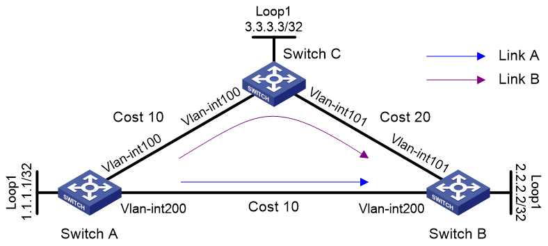
Table 4 Interface and IP address assignment
|
Device |
Interface |
IP address |
Device |
Interface |
IP address |
|
Switch A |
Loop1 |
1.1.1.1/32 |
Switch B |
Loop1 |
2.2.2.2/32 |
|
|
Vlan-Int100 |
12.12.12.1/24 |
|
Vlan-Int101 |
24.24.24.1/24 |
|
|
Vlan-Int200 |
13.13.13.1/24 |
|
Vlan-Int200 |
13.13.13.2/24 |
|
Switch C |
Loop1 |
3.3.3.3/32 |
|
|
|
|
|
Vlan-Int100 |
12.12.12.2/24 |
|
|
|
|
|
Vlan-Int101 |
24.24.24.2/24 |
|
|
|
Procedure
1. Configure IP addresses and masks for interfaces. (Details not shown.)
2. Configure IS-IS on the switches to achieve network level connectivity and set the IS-IS cost style to wide:
# Configure Switch A.
<SwitchA> system-view
[SwitchA] isis 1
[SwitchA-isis-1] network-entity 00.0000.0000.0001.00
[SwitchA-isis-1] cost-style wide
[SwitchA-isis-1] quit
[SwitchA] interface vlan-interface 100
[SwitchA-Vlan-interface100] isis enable 1
[SwitchA-Vlan-interface100] isis cost 10
[SwitchA-Vlan-interface100] quit
[SwitchA] interface vlan-interface 200
[SwitchA-Vlan-interface200] isis enable 1
[SwitchA-Vlan-interface200] isis cost 10
[SwitchA-Vlan-interface200] quit
[SwitchA] interface loopback 1
[SwitchA-LoopBack1] isis enable 1
[SwitchA-LoopBack1] quit
# Configure Switch B.
<SwitchB> system-view
[SwitchB] isis 1
[SwitchB-isis-1] network-entity 00.0000.0000.0002.00
[SwitchB-isis-1] cost-style wide
[SwitchB-isis-1] quit
[SwitchB] interface vlan-interface 101
[SwitchB-Vlan-interface101] isis enable 1
[SwitchB-Vlan-interface101] isis cost 20
[SwitchB-Vlan-interface101] quit
[SwitchB] interface vlan-interface 200
[SwitchB-Vlan-interface200] isis enable 1
[SwitchB-Vlan-interface200] isis cost 10
[SwitchB-Vlan-interface200] quit
[SwitchB] interface loopback 1
[SwitchB-LoopBack1] isis enable 1
[SwitchB-LoopBack1] quit
# Configure Switch C.
<SwitchC> system-view
[SwitchC] isis 1
[SwitchC-isis-1] network-entity 00.0000.0000.0003.00
[SwitchC-isis-1] cost-style wide
[SwitchC-isis-1] quit
[SwitchC] interface vlan-interface 100
[SwitchC-Vlan-interface100] isis enable 1
[SwitchC-Vlan-interface100] isis cost 10
[SwitchC-Vlan-interface100] quit
[SwitchC] interface vlan-interface 101
[SwitchC-Vlan-interface101] isis enable 1
[SwitchC-Vlan-interface101] isis cost 20
[SwitchC-Vlan-interface101] quit
[SwitchC] interface loopback 1
[SwitchC-LoopBack1] isis enable 1
[SwitchC-LoopBack1] quit
3. Enable MPLS SR and MPLS SR adjacency label allocation:
# Configure Switch A.
[SwitchA] isis 1
[SwitchA-isis-1] address-family ipv4
[SwitchA-isis-1-ipv4] segment-routing mpls
[SwitchA-isis-1-ipv4] segment-routing adjacency enable
[SwitchA-isis-1-ipv4] quit
# Configure Switch B.
[SwitchB] isis 1
[SwitchB-isis-1] address-family ipv4
[SwitchB-isis-1-ipv4] segment-routing mpls
[SwitchB-isis-1-ipv4] segment-routing adjacency enable
[SwitchB-isis-1-ipv4] quit
# Configure Switch C.
[SwitchC] isis 1
[SwitchC-isis-1] address-family ipv4
[SwitchC-isis-1-ipv4] segment-routing mpls
[SwitchC-isis-1-ipv4] segment-routing adjacency enable
[SwitchC-isis-1-ipv4] quit
4. Configure SRGBs:
# Configure Switch A.
[SwitchA-isis-1] segment-routing global-block 16000 16999
[SwitchA-isis-1] quit
# Configure Switch B.
[SwitchB-isis-1] segment-routing global-block 17000 17999
[SwitchB-isis-1] quit
# Configure Switch C.
[SwitchC-isis-1] segment-routing global-block 18000 18999
[SwitchC-isis-1] quit
5. Configure IS-IS prefix SIDs for the switches:
# Configure Switch A.
[SwitchA] interface loopback 1
[SwitchA-LoopBack1] isis prefix-sid index 10
[SwitchA-LoopBack1] quit
# Configure Switch B.
[SwitchB] interface loopback 1
[SwitchB-LoopBack1] isis prefix-sid index 20
[SwitchB-LoopBack1] quit
# Configure Switch C.
[SwitchC] interface loopback 1
[SwitchC-LoopBack1] isis prefix-sid index 30
[SwitchC-LoopBack1] quit
6. Configure TI-LFA FRR:
# Configure Switch A.
[SwitchA] isis 1
[SwitchA-isis-1] address-family ipv4
[SwitchA-isis-1-ipv4] fast-reroute lfa
[SwitchA-isis-1-ipv4] fast-reroute ti-lfa
[SwitchA-isis-1-ipv4] quit
[SwitchA-isis-1] quit
# Configure Switch B.
[SwitchB] isis 1
[SwitchB-isis-1] address-family ipv4
[SwitchB-isis-1-ipv4] fast-reroute lfa
[SwitchB-isis-1-ipv4] fast-reroute ti-lfa
[SwitchB-isis-1-ipv4] quit
[SwitchB-isis-1] quit
# Configure Switch C.
[SwitchC] isis 1
[SwitchC-isis-1] address-family ipv4
[SwitchC-isis-1-ipv4] fast-reroute lfa
[SwitchC-isis-1-ipv4] fast-reroute ti-lfa
[SwitchC-isis-1-ipv4] quit
[SwitchC-isis-1] quit
Verifying the configuration
# Display IPv4 IS-IS routing information for 2.2.2.2/32 on Switch A.
[SwitchA] display isis route ipv4 2.2.2.2 32 verbose level-1 1
Route information for IS-IS(1)
-----------------------------
Level-1 IPv4 Forwarding Table
-----------------------------
IPv4 Dest : 2.2.2.2/32 Int. Cost : 10 Ext. Cost : NULL
Admin Tag : - Src Count : 1 Flag : R/L/-
InLabel : 16020 InLabel Flag: -/N/-/-/-/-
NextHop : Interface : ExitIndex :
13.13.13.2 Vlan200 0x00000103
Nib ID : 0x14000005 OutLabel : 17020 OutLabelFlag: I
LabelSrc : SR
TI-LFA:
Interface : Vlan100
BkNextHop : 12.12.12.2 LsIndex : 0x00000002
Backup label stack(top->bottom): {18030, 2175}
Route label: 17020
Flags: D-Direct, R-Added to Rib, L-Advertised in LSPs, U-Up/Down Bit Set
InLabel flags: R-Readvertisement, N-Node SID, P-no PHP
E-Explicit null, V-Value, L-Local
OutLabelFlags: E-Explicit null, I-Implicit null, N-Nomal, P-SR label prefer
The output shows TI-LFA backup next hop information.