- Table of Contents
- Related Documents
-
| Title | Size | Download |
|---|---|---|
| 01-H3C_IRF_Configuration_Examples | 436.06 KB |
|
|
|
H3C IRF Configuration Examples |
|
|
|
|
|
|
Software version: Release 7595
Document version: 6W100-20201031
Copyright © 2020 New H3C Technologies Co., Ltd. All rights reserved.
No part of this manual may be reproduced or transmitted in any form or by any means without prior written consent of New H3C Technologies Co., Ltd.
Except for the trademarks of New H3C Technologies Co., Ltd., any trademarks that may be mentioned in this document are the property of their respective owners.
The information in this document is subject to change without notice.
Contents
General restrictions and guidelines
Hardware compatibility with IRF
Bridge MAC restrictions for IRF member devices
Candidate IRF physical interfaces
IRF physical interface configuration restrictions and guidelines
Command configuration restrictions
Feature compatibility and configuration restrictions
MAD configuration restrictions
Example: Setting up a LACP MAD-enabled two-chassis IRF fabric
Verifying the link backup function of multichassis aggregations
Verifying the link backup function of IRF connections
Example: Setting up a LACP MAD-enabled four-chassis IRF fabric
Verifying the link backup function of multichassis aggregations
Example: Upgrading a two-chassis IRF fabric to a four-chassis IRF fabric (BFD MAD)
Adding two chassis to a two-chassis IRF fabric
Merging two two-chassis IRF fabrics
Verifying the link backup function of multichassis aggregations
Introduction
This document provides examples for deploying two-chassis IRF fabrics and four-chassis IRF fabrics.
Prerequisites
The configuration examples in this document were created and verified in a lab environment, and all the devices were started with the factory default configuration. When you are working on a live network, make sure you understand the potential impact of every command on your network.
This document assumes that you have basic knowledge of H3C IRF.
General restrictions and guidelines
When you set up and configure an IRF fabric, follow the restrictions and guidelines in this section.
Hardware compatibility with IRF
An H3C S7500X switch can form an IRF fabric only with devices in the same series.
All member devices in an IRF fabric must use the same type of MPUs.
Software requirements for IRF
All IRF member devices must run the same software image version. Make sure the software auto-update feature is enabled on all member devices.
IRF fabric size
An S7500X IRF fabric supports a maximum of four chassis.
Bridge MAC restrictions for IRF member devices
Each member device must have a unique bridge MAC address. IRF setup fails if any two member devices have the same bridge MAC address.
Candidate IRF physical interfaces
Use the following physical interfaces for IRF links:
· 10-GE fiber ports.
· 40-GE fiber ports.
· 100-GE fiber ports.
IRF port connection
When you connect neighboring IRF members, connect the physical interfaces of IRF-port 1 on one member to the physical interfaces of IRF-port 2 on the other (see Figure 1). On neighboring members, IRF ports with the same port index cannot have physical connections.
Figure 1 Connecting IRF physical interfaces
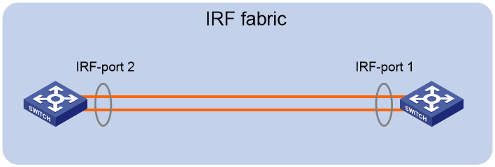
To use the ring topology, you must have a minimum of three member devices.
IRF physical interface configuration restrictions and guidelines
· Grouped port binding restrictions
Restrictions on grouped 10-GE ports on interface modules
The 10-GE ports on the LSQM1TGS12EC0 interface module are grouped by port number in order, starting from 1. Each group contains four ports.
The ports on the LSQM2TGS16SF0 interface module are divided into the following groups:
· Ports 1, 2, 15, and 16.
· Ports 3 through 5.
· Ports 6 through 8.
· Ports 9 through 11.
· Ports 12 through 14.
If you use the ports in a group for IRF links, follow these restrictions and guidelines:
· You must use all or none of the ports for IRF links. The ports can be bound to different IRF ports.
· Before you bind one 10-GE port to an IRF port or remove it from the IRF port, you must shut down all the ports in the group. If any of the ports are in up state, the bind or remove action will fail.
· Bring up the ports after you complete the operations.
Restrictions on 40-GE QSFP+ ports on interface modules
Port split (the using tengige command) and combination (the using fortygige command) require a card reboot. As a best practice to avoid topology change, complete these operations before you add the device to an IRF fabric. When you perform these operations on an IRF fabric, make sure you understand the impact on the IRF fabric topology. For more information about 40-GE port split and combination operations, see Interface Configuration Guide.
If you use the 40-GE QSFP+ ports on interface modules for IRF links, follow these restrictions and guidelines:
· You can use a 40-GE QSFP+ port for IRF links, or use the breakout interfaces of the QSFP+ port for IRF links.
· If you use the 10-GE breakout interfaces of a 40-GE port for IRF links, follow these restrictions and guidelines:
¡ You must use all or none of the four 10-GE breakout interfaces for IRF links. The four breakout interfaces can be bound to different IRF ports.
¡ Before you bind one 10-GE breakout interface to an IRF port or remove it from the IRF port, you must shut down all the 10-GE breakout interfaces. If any of the breakout interfaces are in up state, the bind or remove action will fail.
¡ Bring up the breakout interfaces after you complete the operations.
Command configuration restrictions
On a physical interface bound to an IRF port, you can execute only the following commands:
· Interface commands, including:
¡ description.
¡ flow-interval.
¡ shutdown.
For more information about these commands, see Interface Command Reference.
· MAC address table configuration commands, including the mac-address static source-check enable command. To ensure successful forwarding of Layer 3 traffic across member devices, use the undo mac-address static source-check enable command on each IRF physical interface. For information about this command, see Layer 2—LAN Switching Command Reference.
· LLDP commands, including:
¡ lldp admin-status.
¡ lldp check-change-interval.
¡ lldp enable.
¡ lldp encapsulation snap.
¡ lldp notification remote-change enable.
¡ lldp tlv-enable.
For more information about these commands, see Layer 2—LAN Switching Command Reference.
Feature compatibility and configuration restrictions
ECMP
To form an IRF fabric, all member devices in the IRF fabric must support the same maximum number of ECMP routes. For more information about ECMP, see Layer 3—IP Routing Configuration Guide.
System operating mode
All member devices in the IRF fabric must work in the same system operating mode (set by using the system-working-mode command). For more information about the system operating mode, see Fundamentals Configuration Guide.
MAD configuration restrictions
You can configure a minimum of one MAD mechanism on an IRF fabric for prompt IRF split detection.
· Do not configure LACP MAD together with ARP MAD or ND MAD, because they handle collisions differently.
· Do not configure BFD MAD together with ARP MAD or ND MAD. BFD MAD is mutually exclusive with the spanning tree feature. ARP MAD and ND MAD require the spanning tree feature.
Licensing requirements
For a license-based feature to run correctly on an IRF fabric, make sure the licenses installed for the feature on all member devices are the same. For more information about feature licensing, see Fundamentals Configuration Guide.
Example: Setting up a LACP MAD-enabled two-chassis IRF fabric
Network configuration
As shown in Figure 2:
· Set up a two-chassis IRF fabric at the core layer of the network.
· Use multichassis link aggregations to connect the IRF fabric to the access switches and the upstream egress routers.
· Use LACP MAD to detect IRF split.
· Run OSPF between the IRF fabric and the egress routers.
Figure 2 LACP MAD-enabled two-chassis IRF fabric
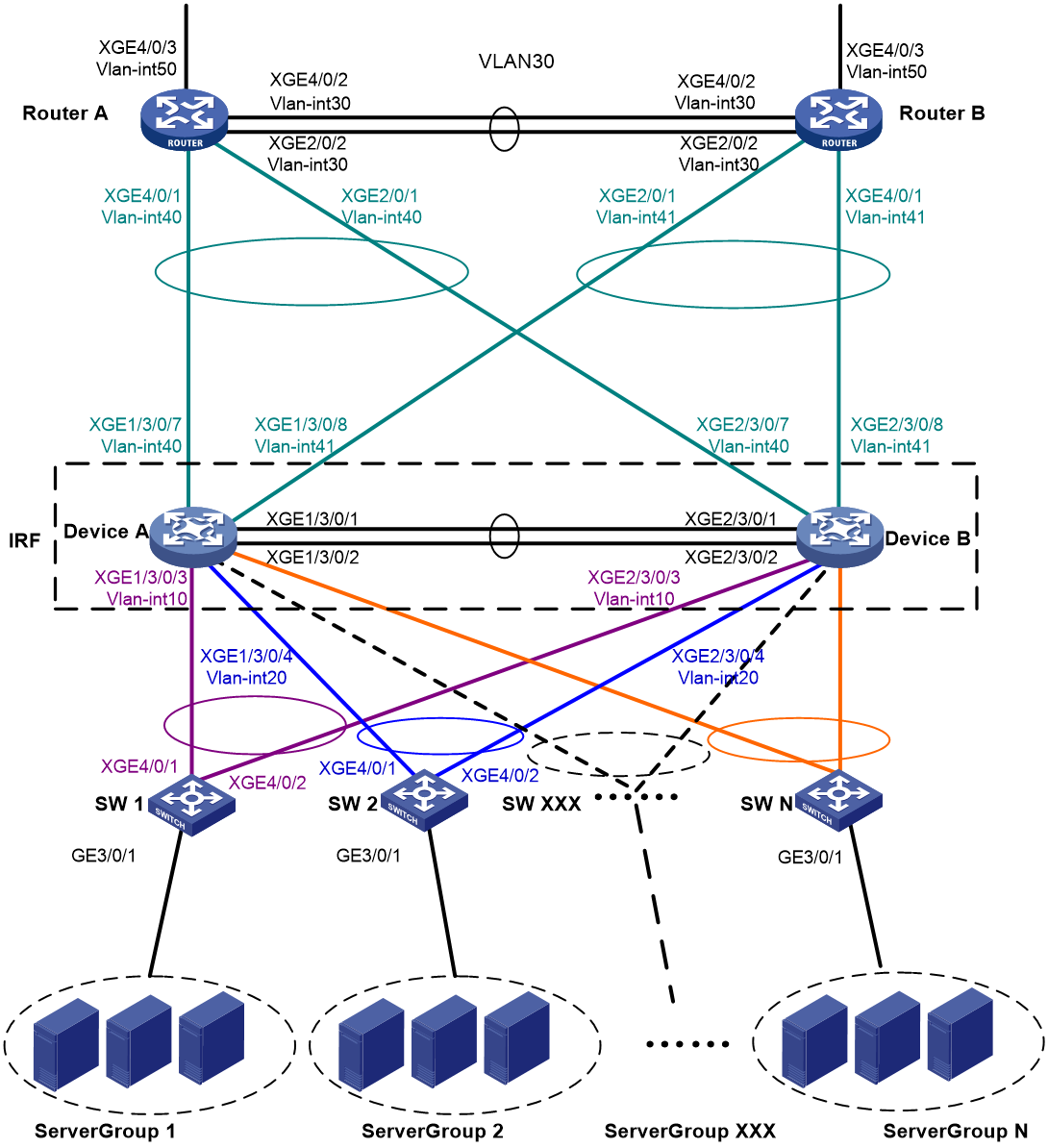
Table 1 VLAN and IP address assignment
|
Device |
VLAN interface |
IP address |
|
Router A |
VLAN-interface 30 |
172.24.2.2/24 |
|
Router A |
VLAN-interface 40 |
172.24.40.2/24 |
|
Router A |
VLAN-interface 50 |
172.24.1.2/24 |
|
Router B |
VLAN-interface 30 |
172.24.2.3/24 |
|
Router B |
VLAN-interface 41 |
172.24.41.3/24 |
|
Router B |
VLAN-interface 50 |
172.24.4.3/24 |
|
IRF fabric |
VLAN-interface 10 |
172.24.10.254/24 |
|
IRF fabric |
VLAN-interface 20 |
172.24.20.254/24 |
|
IRF fabric |
VLAN-interface 40 |
172.24.40.254/24 |
|
IRF fabric |
VLAN-interface 41 |
172.24.41.254/24 |
Analysis
For LACP MAD to run correctly, ensure that the intermediate device supports extended LACPDUs for LACP MAD.
To avoid single points of failure, use multichassis link aggregations to connect the IRF fabric to the downstream and upstream devices.
You do not need to run LACP MAD on all link aggregations. You can detect IRF split effectively by running LACP MAD on one dynamic link aggregation.
Restrictions and guidelines
When you configure LACP MAD on a link aggregation, follow these restrictions and guidelines:
· The link aggregation must use dynamic aggregation mode.
· The link aggregation must have a minimum of one member link from each member chassis.
· If the intermediate device is also an IRF fabric, you must assign the two IRF fabrics different domain IDs for correct split detection.
Procedures
Setting up the IRF fabric
1. Configure Device A:
# Assign member ID 1 to Device A.
<DeviceA> system-view
[DeviceA] irf member 1
# Bind Ten-GigabitEthernet 3/0/1 and Ten-GigabitEthernet 3/0/2 to IRF-port 2.
[DeviceA] irf-port 2
[DeviceA-irf-port2] port group interface ten-gigabitethernet 3/0/1
[DeviceA-irf-port2] port group interface ten-gigabitethernet 3/0/2
[DeviceA-irf-port2] quit
# Save the running configuration to the main next-startup configuration file before changing the operating mode to IRF.
|
|
IMPORTANT: The mode change requires a system reboot, which causes all unsaved settings to be lost. |
[DeviceA] save
# Enable IRF mode.
[DeviceA] chassis convert mode irf
The device will switch to IRF mode and reboot. Continue? [Y/N]:y
You are recommended to save the current running configuration and specify the co
nfiguration file for the next startup. Continue? [Y/N]:y
Do you want to convert the content of the next startup configuration file cfa0:/
irf.cfg to make it available in stack mode? [Y/N]:y
Now rebooting, please wait...
2. Configure Device B:
# Assign member ID 2 to Device B.
<DeviceB> system-view
[DeviceB] irf member 2
# Bind Ten-GigabitEthernet 3/0/1 and Ten-GigabitEthernet 3/0/2 to IRF-port 1.
[DeviceB] irf-port 1
[DeviceB-irf-port1] port group interface ten-gigabitethernet 3/0/1
[DeviceB-irf-port1] port group interface ten-gigabitethernet 3/0/2
[DeviceB-irf-port1] quit
# Save the configuration.
[DeviceB] save
# Connect IRF-port 2 on Device A to IRF-port 1 on Device B, as shown in Figure 2.
# Enable IRF mode.
[DeviceB] chassis convert mode irf
The device will switch to IRF mode and reboot. Continue? [Y/N]:y
You are recommended to save the current running configuration and specify the co
nfiguration file for the next startup. Continue? [Y/N]:y
Do you want to convert the content of the next startup configuration file cfa0:/
irf.cfg to make it available in stack mode? [Y/N]:y
Now rebooting, please wait...
Configuring software features
This example provides only basic software feature configuration.
Configuring the IRF fabric
After the IRF fabric is formed, the master's system name becomes the fabric's system name. You can configure software features on the fabric as you do on a standalone device.
1. Configure link aggregations:
# Create a Layer 2 dynamic aggregate interface Bridge-Aggregation 1. Enable LACP MAD on the aggregate interface.
<DeviceA> system-view
[DeviceA] interface bridge-aggregation 1
[DeviceA-Bridge-Aggregation1] link-aggregation mode dynamic
[DeviceA-Bridge-Aggregation1] mad enable
You need to assign a domain ID (range: 0-4294967295)
[Current domain is: 0]:
The assigned domain ID is: 0
[DeviceA-Bridge-Aggregation1] quit
# Assign the downlink ports that connect to SW 1 to the aggregation group of Bridge-Aggregation 1.
[DeviceA] interface ten-gigabitethernet 1/3/0/3
[DeviceA-Ten-GigabitEthernet1/3/0/3] port link-aggregation group 1
[DeviceA-Ten-GigabitEthernet1/3/0/3] quit
[DeviceA] interface ten-gigabitethernet 2/3/0/3
[DeviceA-Ten-GigabitEthernet2/3/0/3] port link-aggregation group 1
[DeviceA-Ten-GigabitEthernet2/3/0/3] quit
# Create Bridge-Aggregation 2. Assign the downlink ports that connect to SW 2 to the aggregation group.
[DeviceA] interface bridge-aggregation 2
[DeviceA-Bridge-Aggregation2] quit
[DeviceA] interface ten-gigabitethernet 1/3/0/4
[DeviceA-Ten-GigabitEthernet1/3/0/4] port link-aggregation group 2
[DeviceA-Ten-GigabitEthernet1/3/0/4] quit
[DeviceA] interface ten-gigabitethernet 2/3/0/4
[DeviceA-Ten-GigabitEthernet2/3/0/4] port link-aggregation group 2
[DeviceA-Ten-GigabitEthernet2/3/0/4] quit
# Create Bridge-Aggregation 1023. Assign the uplink ports that connect to Router A to Bridge-Aggregation 1023.
[DeviceA] interface bridge-aggregation 1023
[DeviceA-Bridge-Aggregation1023] quit
[DeviceA] interface ten-gigabitethernet 1/3/0/7
[DeviceA-Ten-GigabitEthernet1/3/0/7] port link-aggregation group 1023
[DeviceA-Ten-GigabitEthernet1/3/0/7] quit
[DeviceA] interface ten-gigabitethernet 2/3/0/7
[DeviceA-Ten-GigabitEthernet2/3/0/7] port link-aggregation group 1023
[DeviceA-Ten-GigabitEthernet2/3/0/7] quit
# Create Bridge-Aggregation 1024. Assign the uplink ports that connect to Router B to Bridge-Aggregation 1024.
[DeviceA] interface bridge-aggregation 1024
[DeviceA-Bridge-Aggregation1024] quit
[DeviceA] interface ten-gigabitethernet 1/3/0/8
[DeviceA-Ten-GigabitEthernet1/3/0/8] port link-aggregation group 1024
[DeviceA-Ten-GigabitEthernet1/3/0/8] quit
[DeviceA] interface ten-gigabitethernet 2/3/0/8
[DeviceA-Ten-GigabitEthernet2/3/0/8] port link-aggregation group 1024
[DeviceA-Ten-GigabitEthernet2/3/0/8] quit
2. Configure VLANs, ports, and IP addresses:
# Create VLAN 10, assign an IP address to VLAN-interface 10, and assign Bridge-Aggregation 1 to VLAN 10.
[DeviceA]vlan 10
[DeviceA-vlan10] quit
[DeviceA] interface vlan-interface 10
[DeviceA-Vlan-interface10] ip address 172.24.10.254 24
[DeviceA-Vlan-interface10] quit
[DeviceA] interface bridge-aggregation 1
[DeviceA-Bridge-Aggregation1] port link-type trunk
[DeviceA-Bridge-Aggregation1] undo port trunk permit vlan 1
[DeviceA-Bridge-Aggregation1] port trunk permit vlan 10
[DeviceA-Bridge-Aggregation1] quit
# Create VLAN 20, assign an IP address to VLAN-interface 20, and assign Bridge-Aggregation 2 to VLAN 20.
[DeviceA] vlan 20
[DeviceA-vlan20] quit
[DeviceA] interface vlan-interface 20
[DeviceA-Vlan-interface20] ip address 172.24.20.254 24
[DeviceA-Vlan-interface20] quit
[DeviceA] interface bridge-aggregation 2
[DeviceA-Bridge-Aggregation2] port link-type trunk
[DeviceA-Bridge-Aggregation2] undo port trunk permit vlan 1
[DeviceA-Bridge-Aggregation2] port trunk permit vlan 20
[DeviceA-Bridge-Aggregation2] quit
# Create VLAN 40, assign an IP address to VLAN-interface 40, and assign Bridge-Aggregation 1023 to VLAN 40.
[DeviceA] vlan 40
[DeviceA-vlan40] quit
[DeviceA] interface vlan-interface 40
[DeviceA-Vlan-interface40] ip address 172.24.40.254 24
[DeviceA-Vlan-interface40] quit
[DeviceA] interface bridge-aggregation 1023
[DeviceA-Bridge-Aggregation1023] port access vlan 40
[DeviceA-Bridge-Aggregation1023] quit
# Create VLAN 41, assign an IP address to VLAN-interface 41, and assign Bridge-Aggregation 1024 to VLAN 41.
[DeviceA] vlan 41
[DeviceA-vlan41] quit
[DeviceA] interface vlan-interface 41
[DeviceA-Vlan-interface41] ip address 172.24.41.254 24
[DeviceA-Vlan-interface41] quit
[DeviceA] interface bridge-aggregation 1024
[DeviceA-Bridge-Aggregation1024] port access vlan 41
[DeviceA-Bridge-Aggregation1024] quit
3. Configure OSPF between the IRF fabric and the egress routers.
[DeviceA] ospf
[DeviceA-ospf-1] import-route direct
[DeviceA-ospf-1] area 0
[DeviceA-ospf-1-area-0.0.0.0] network 172.24.40.0 0.0.0.255
[DeviceA-ospf-1-area-0.0.0.0] network 172.24.41.0 0.0.0.255
[DeviceA-ospf-1-area-0.0.0.0] quit
[DeviceA-ospf-1] quit
Configuring SW 1
1. Configure a link aggregation:
# Create Bridge-Aggregation 1 and enable the dynamic aggregation mode. You must enable the dynamic aggregation mode because this link aggregation will be used for LACP MAD.
<SW1> system-view
[SW1] interface bridge-aggregation 1
[SW1-Bridge-Aggregation1] link-aggregation mode dynamic
[SW1-Bridge-Aggregation1] quit
# Assign the uplink ports that connect to the IRF fabric to Bridge-Aggregation 1.
[SW1] interface ten-gigabitethernet 4/0/1
[SW1-Ten-GigabitEthernet4/0/1] port link-aggregation group 1
[SW1-Ten-GigabitEthernet4/0/1] quit
[SW1] interface ten-gigabitethernet 4/0/2
[SW1-Ten-GigabitEthernet4/0/2] port link-aggregation group 1
[SW1-Ten-GigabitEthernet4/0/2] quit
2. Configure VLANs, ports, and IP addresses:
# Create all VLANs.
[SW1] vlan all
# Configure VLAN settings on the uplink aggregate interface that connects to the IRF fabric.
[SW1] interface bridge-aggregation 1
[SW1-Bridge-Aggregation1] port link-type trunk
[SW1-Bridge-Aggregation1] undo port trunk permit vlan 1
[SW1-Bridge-Aggregation1] port trunk permit vlan 10
[SW1-Bridge-Aggregation1] quit
# Configure VLAN settings on the port that connects to Server Group 1.
[SW1] interface gigabitethernet 3/0/1
[SW1-GigabitEthernet3/0/1] port link-type trunk
[SW1-GigabitEthernet3/0/1] port trunk permit vlan all
[SW1-GigabitEthernet3/0/1] undo port trunk permit vlan 1
[SW1-GigabitEthernet3/0/1] quit
Configuring SW 2
1. Configure a link aggregation:
# Create Bridge-Aggregation 1.
<SW2>system-view
[SW2] interface bridge-aggregation 1
[SW2-Bridge-Aggregation1] quit
# Assign the uplink ports that connect to the IRF fabric to Bridge-Aggregation 1.
[SW2] interface ten-gigabitethernet 4/0/1
[SW2-Ten-GigabitEthernet4/0/1] port link-aggregation group 1
[SW2-Ten-GigabitEthernet4/0/1] quit
[SW2] interface ten-gigabitethernet 4/0/2
[SW2-Ten-GigabitEthernet4/0/2] port link-aggregation group 1
[SW2-Ten-GigabitEthernet4/0/2] quit
2. Configure VLANs, ports, and IP addresses:
# Create all VLANs.
[SW2] vlan all
# Configure VLAN settings on the uplink aggregate interface that connects to the IRF fabric.
[SW2] interface bridge-aggregation 1
[SW2-Bridge-Aggregation1] port link-type trunk
[SW2-Bridge-Aggregation1] undo port trunk permit vlan 1
[SW2-Bridge-Aggregation1] port trunk permit vlan 20
[SW2-Bridge-Aggregation1] quit
# Configure VLAN settings on the port that connects to Server Group 2.
[SW2] interface gigabitethernet 3/0/1
[SW2-GigabitEthernet3/0/1] port link-type trunk
[SW2-GigabitEthernet3/0/1] port trunk permit vlan all
[SW2-GigabitEthernet3/0/1] undo port trunk permit vlan 1
[SW2-GigabitEthernet3/0/1] quit
Configuring Router A
In this example, the egress router configuration only includes the connection to the IRF fabric.
1. Configure link aggregations:
# Create Bridge-Aggregation 1. Assign the downlink ports that connect to the IRF fabric to Bridge-Aggregation 1.
<RouterA> system-view
[RouterA] interface bridge-aggregation 1
[RouterA-Bridge-Aggregation1] quit
[RouterA] interface ten-gigabitethernet 4/0/1
[RouterA-Ten-GigabitEthernet4/0/1] port link-mode bridge
[RouterA-Ten-GigabitEthernet4/0/1] port link-aggregation group 1
[RouterA-Ten-GigabitEthernet4/0/1] quit
[RouterA] interface ten-gigabitethernet 2/0/1
[RouterA-Ten-GigabitEthernet2/0/1] port link-mode bridge
[RouterA-Ten-GigabitEthernet2/0/1] port link-aggregation group 1
[RouterA-Ten-GigabitEthernet2/0/1] quit
# Create Bridge-Aggregation 2. Assign the ports that connect to Router B to Bridge-Aggregation 2.
[RouterA] interface bridge-aggregation 2
[RouterA-Bridge-Aggregation2] quit
[RouterA] interface ten-gigabitethernet 4/0/2
[RouterA-Ten-GigabitEthernet4/0/2] port link-mode bridge
[RouterA-Ten-GigabitEthernet4/0/2] port link-aggregation group 2
[RouterA-Ten-GigabitEthernet4/0/2] quit
[RouterA] interface ten-gigabitethernet 2/0/2
[RouterA-Ten-GigabitEthernet2/0/2] port link-mode bridge
[RouterA-Ten-GigabitEthernet2/0/2] port link-aggregation group 2
[RouterA-Ten-GigabitEthernet2/0/2] quit
2. Configure VLANs, ports, and IP addresses:
# Create VLAN 40, assign an IP address to VLAN-interface 40, and assign Bridge-Aggregation 1 to VLAN 40.
[RouterA] vlan 40
[RouterA-vlan40] quit
[RouterA] interface vlan-interface 40
[RouterA-vlan-interface40] ip address 172.24.40.2 24
[RouterA-vlan-interface40] quit
[RouterA] interface bridge-aggregation 1
[RouterA-Bridge-Aggregation1] port access vlan 40
[RouterA-Bridge-Aggregation1] quit
# Create VLAN 30, assign an IP address to VLAN-interface 30, and assign Bridge-Aggregation 2 to VLAN 30.
[RouterA] vlan 30
[RouterA-vlan30] quit
[RouterA] interface vlan-interface 30
[RouterA-vlan-interface30] ip address 172.24.2.2 24
[RouterA-vlan-interface30] quit
[RouterA] interface bridge-aggregation 2
[RouterA-Bridge-Aggregation2] port link-type access
[RouterA-Bridge-Aggregation2] port access vlan 30
[RouterA-Bridge-Aggregation2] quit
# Create VLAN 50, assign an IP address to VLAN-interface 50, and assign Ten-GigabitEthernet 4/0/3 to VLAN 50.
[RouterA] vlan 50
[RouterA-vlan50] quit
[RouterA] interface vlan-interface 50
[RouterA-vlan-interface50] ip address 172.24.1.2 24
[RouterA-vlan-interface50] quit
[RouterA] interface ten-gigabitethernet 4/0/3
[RouterA-Ten-GigabitEthernet4/0/3] port link-mode bridge
[RouterA-Ten-GigabitEthernet4/0/3] port access vlan 50
[RouterA-Ten-GigabitEthernet4/0/3] quit
3. Configure OSPF between Router A and the IRF fabric.
[RouterA] ospf
[RouterA-ospf-1] import-route direct
[RouterA-ospf-1] area 0
[RouterA-ospf-1-area-0.0.0.0] network 172.24.40.0 0.0.0.255
[RouterA-ospf-1-area-0.0.0.0] network 172.24.2.0 0.0.0.255
[RouterA-ospf-1-area-0.0.0.0] quit
[RouterA-ospf-1] quit
Configuring Router B
In this example, the egress router configuration only includes the connection to the IRF fabric.
1. Configure link aggregations:
# Create Bridge-Aggregation 1. Assign the downlink ports that connect to the IRF fabric to Bridge-Aggregation 1.
<RouterB> system-view
[RouterB] interface bridge-aggregation 1
[RouterB-Bridge-Aggregation1] quit
[RouterB] interface ten-gigabitethernet 4/0/1
[RouterB-Ten-GigabitEthernet4/0/1] port link-mode bridge
[RouterB-Ten-GigabitEthernet4/0/1] port link-aggregation group 1
[RouterB-Ten-GigabitEthernet4/0/1] quit
[RouterB] interface ten-gigabitethernet 2/0/1
[RouterB-Ten-GigabitEthernet2/0/1] port link-mode bridge
[RouterB-Ten-GigabitEthernet2/0/1] port link-aggregation group 1
[RouterB-Ten-GigabitEthernet2/0/1] quit
# Create Bridge-Aggregation 2. Assign the ports that connect to Router A to Bridge-Aggregation 2.
[RouterB] interface bridge-aggregation 2
[RouterB-Bridge-Aggregation2] quit
[RouterB] interface ten-gigabitethernet 4/0/2
[RouterB-Ten-GigabitEthernet4/0/2] port link-mode bridge
[RouterB-Ten-GigabitEthernet4/0/2] port link-aggregation group 2
[RouterB-Ten-GigabitEthernet4/0/2] quit
[RouterB] interface ten-gigabitethernet 2/0/2
[RouterB-Ten-GigabitEthernet2/0/2] port link-mode bridge
[RouterB-Ten-GigabitEthernet2/0/2] port link-aggregation group 2
[RouterB-Ten-GigabitEthernet2/0/2] quit
2. Configure VLANs, ports, and IP addresses:
# Create VLAN 41, assign an IP address to VLAN-interface 41, and assign Bridge-Aggregation 1 to VLAN 41.
[RouterB] vlan 41
[RouterB-vlan41] quit
[RouterB] interface vlan-interface 41
[RouterB-vlan-interface41] ip address 172.24.41.3 24
[RouterB-vlan-interface41] quit
[RouterB] interface bridge-aggregation 1
[RouterB-Bridge-Aggregation1] port access vlan 41
[RouterB-Bridge-Aggregation1] quit
# Create VLAN 30, assign an IP address to VLAN-interface 30, and assign Bridge-Aggregation 2 to VLAN 30.
[RouterB] vlan 30
[RouterB-vlan30] quit
[RouterB] interface vlan-interface 30
[RouterB-vlan-interface30] ip address 172.24.2.3 24
[RouterB-vlan-interface30] quit
[RouterB] interface bridge-aggregation 2
[RouterB-Bridge-Aggregation2] port link-type access
[RouterB-Bridge-Aggregation2] port access vlan 30
[RouterB-Bridge-Aggregation2] quit
# Create VLAN 50, assign an IP address to VLAN-interface 50, and assign Ten-GigabitEthernet 4/0/3 to VLAN 50.
[RouterB] vlan 50
[RouterB-vlan50] quit
[RouterB] interface vlan-interface 50
[RouterB-vlan-interface50] ip address 172.24.4.3 24
[RouterB-vlan-interface50] quit
[RouterB] interface ten-gigabitethernet 4/0/3
[RouterB-Ten-GigabitEthernet4/0/3] port link-mode bridge
[RouterB-Ten-GigabitEthernet4/0/3] port access vlan 50
[RouterB-Ten-GigabitEthernet4/0/3] quit
3. Configure OSPF between Router B and the IRF fabric.
[RouterB] ospf
[RouterB-ospf-1] import-route direct
[RouterB-ospf-1] area 0
[RouterB-ospf-1-area-0.0.0.0] network 172.24.41.0 0.0.0.255
[RouterB-ospf-1-area-0.0.0.0] network 172.24.2.0 0.0.0.255
[RouterB-ospf-1-area-0.0.0.0] quit
[RouterB-ospf-1] quit
Verifying the configuration
Verify the IRF function, multichassis link aggregation configuration, and the IRF link redundancy backup function.
Verifying the IRF function
# Execute the display irf command in any view.
[DeviceA] display irf
MemberID Slot Role Priority CPU-Mac Description
*+1 0 Master 1 0210-fc01-0000 ---
2 0 Standby 1 0210-fc02-0000 ---
--------------------------------------------------
* indicates the device is the master.
+ indicates the device through which the user logs in.
The Bridge MAC of the IRF is: 3822-d60f-2800
Auto upgrade : yes
Mac persistent : always
Domain ID : 0
Auto merge : yes
IRF mode : normal
The command output shows that the member chassis have formed an IRF fabric.
Verifying the link backup function of multichassis aggregations
# Shut down Ten-GigabitEthernet 1/3/0/8, the port connected to the egress router.
[DeviceA] interface ten-gigabitethernet 1/3/0/8
[DeviceA-Ten-GigabitEthernet1/3/0/8] shutdown
# Ping an IP address on the public network from a PC in Server Group 1.
C:\Users>ping 202.108.22.5 -t
Pinging 202.108.22.5 with 32 bytes of data:
Reply from 202.108.22.5: bytes=32 time=1ms TTL=122
Reply from 202.108.22.5: bytes=32 time=13ms TTL=122
Reply from 202.108.22.5: bytes=32 time<1ms TTL=122
Request timed out.
Request timed out.
Request timed out.
Reply from 202.108.22.5: bytes=32 time<1ms TTL=122
Reply from 202.108.22.5: bytes=32 time<1ms TTL=122
Reply from 202.108.22.5: bytes=32 time<1ms TTL=122
The output shows that the address can be pinged after transient traffic disruption.
# Bring up Ten-GigabitEthernet 1/3/0/8 and shut down Ten-GigabitEthernet 2/3/0/8.
[DeviceA-Ten-GigabitEthernet1/3/0/8] undo shutdown
[DeviceA-Ten-GigabitEthernet1/3/0/8] quit
[DeviceA] interface ten-gigabitethernet 2/3/0/8
[DeviceA-Ten-GigabitEthernet2/3/0/8] shutdown
# Ping the IP address on the public network from the PC.
C:\Users>ping 202.108.22.5 -t
Pinging 202.108.22.5 with 32 bytes of data:
Reply from 202.108.22.5: bytes=32 time=1ms TTL=122
Reply from 202.108.22.5: bytes=32 time=13ms TTL=122
Reply from 202.108.22.5: bytes=32 time<1ms TTL=122
Request timed out.
Request timed out.
Request timed out.
Reply from 202.108.22.5: bytes=32 time<1ms TTL=122
Reply from 202.108.22.5: bytes=32 time<1ms TTL=122
Reply from 202.108.22.5: bytes=32 time<1ms TTL=122
The output shows that the address can be pinged after transient traffic disruption.
Verifying the link backup function of IRF connections
Verify that the IRF fabric is integrated and can forward traffic across member chassis after one IRF connection cable is removed.
Configuration files
· IRF fabric:
#
irf mac-address persistent always
irf auto-update enable
irf auto-merge enable
undo irf link-delay
irf member 1 priority 1
irf member 2 priority 1
#
ospf 1
import-route direct
area 0.0.0.0
network 172.24.40.0 0.0.0.255
network 172.24.41.0 0.0.0.255
#
vlan 10
#
vlan 20
#
vlan 40
#
vlan 41
#
irf-port 1/2
port group interface Ten-GigabitEthernet1/3/0/1 mode enhanced
port group interface Ten-GigabitEthernet1/3/0/2 mode enhanced
#
irf-port 2/1
port group interface Ten-GigabitEthernet2/3/0/1 mode enhanced
port group interface Ten-GigabitEthernet2/3/0/2 mode enhanced
#
interface bridge-aggregation 1
port link-type trunk
undo port trunk permit vlan 1
port trunk permit vlan 10
link-aggregation mode dynamic
mad enable
#
interface bridge-aggregation 2
port link-type trunk
undo port trunk permit vlan 1
port trunk permit vlan 20
#
interface bridge-aggregation 1023
port access vlan 40
#
interface bridge-aggregation 1024
port access vlan 41
#
interface vlan-interface 10
ip address 172.24.10.254 255.255.255.0
#
interface vlan-interface 20
ip address 172.24.20.254 255.255.255.0
#
interface vlan-interface 40
ip address 172.24.40.254 255.255.255.0
#
interface vlan-interface 41
ip address 172.24.41.254 255.255.255.0
#
interface Ten-GigabitEthernet 1/3/0/3
port link-mode bridge
port link-type trunk
undo port trunk permit vlan 1
port trunk permit vlan 10
port link-aggregation group 1
#
interface Ten-GigabitEthernet 1/3/0/4
port link-mode bridge
port link-type trunk
undo port trunk permit vlan 1
port trunk permit vlan 20
port link-aggregation group 2
#
interface Ten-GigabitEthernet 1/3/0/7
port link-mode bridge
port access vlan 40
port link-aggregation group 1023
#
interface Ten-GigabitEthernet 1/3/0/8
port link-mode bridge
port access vlan 41
port link-aggregation group 1024
#
interface Ten-GigabitEthernet 2/3/0/3
port link-mode bridge
port link-type trunk
undo port trunk permit vlan 1
port trunk permit vlan 10
port link-aggregation group 1
#
interface Ten-GigabitEthernet 2/3/0/4
port link-mode bridge
port link-type trunk
undo port trunk permit vlan 1
port trunk permit vlan 20
port link-aggregation group 2
#
interface Ten-GigabitEthernet 2/3/0/7
port link-mode bridge
port access vlan 40
port link-aggregation group 1023
#
interface Ten-GigabitEthernet 2/3/0/8
port link-mode bridge
port access vlan 41
port link-aggregation group 1024
#
· SW 1:
#
vlan 1
#
vlan 2 to 4094
#
interface bridge-aggregation 1
port link-type trunk
undo port trunk permit vlan 1
port trunk permit vlan 10
link-aggregation mode dynamic
#
interface gigabitethernet 3/0/1
port link-mode bridge
port link-type trunk
undo port trunk permit vlan 1
port trunk permit vlan 2 to 4094
#
interface Ten-GigabitEthernet 4/0/1
port link-mode bridge
port link-type trunk
undo port trunk permit vlan 1
port trunk permit vlan 10
port link-aggregation group 1
#
interface Ten-GigabitEthernet 4/0/2
port link-mode bridge
port link-type trunk
undo port trunk permit vlan 1
port trunk permit vlan 10
port link-aggregation group 1
#
· SW 2:
#
vlan 1
#
vlan 2 to 4094
#
interface bridge-aggregation 1
port link-type trunk
undo port trunk permit vlan 1
port trunk permit vlan 20
#
interface gigabitethernet 3/0/1
port link-mode bridge
port link-type trunk
undo port trunk permit vlan 1
port trunk permit vlan 2 to 4094
#
interface Ten-GigabitEthernet 4/0/1
port link-mode bridge
port link-type trunk
undo port trunk permit vlan 1
port trunk permit vlan 20
port link-aggregation group 1
#
interface Ten-GigabitEthernet 4/0/2
port link-mode bridge
port link-type trunk
undo port trunk permit vlan 1
port trunk permit vlan 20
port link-aggregation group 1
#
· Router A:
#
ospf 1
import-route direct
area 0.0.0.0
network 172.24.2.0 0.0.0.255
network 172.24.40.0 0.0.0.255
#
vlan 30
#
vlan 40
#
vlan 50
#
interface bridge-aggregation 1
port access vlan 40
#
interface bridge-aggregation 2
port access vlan 30
#
interface vlan-interface 30
ip address 172.24.2.2 255.255.255.0
#
interface vlan-interface 40
ip address 172.24.40.2 255.255.255.0
#
interface vlan-interface 50
ip address 172.24.1.2 255.255.255.0
#
interface Ten-GigabitEthernet 2/0/1
port link-mode bridge
port access vlan 40
port link-aggregation group 1
#
interface Ten-GigabitEthernet 2/0/2
port link-mode bridge
port access vlan 30
port link-aggregation group 2
#
interface Ten-GigabitEthernet 4/0/1
port link-mode bridge
port access vlan 40
port link-aggregation group 1
#
interface Ten-GigabitEthernet 4/0/2
port link-mode bridge
port access vlan 30
port link-aggregation group 2
#
interface Ten-GigabitEthernet 4/0/3
port link-mode bridge
port access vlan 50
#
· Router B:
#
ospf 1
import-route direct
area 0.0.0.0
network 172.24.2.0 0.0.0.255
network 172.24.41.0 0.0.0.255
#
vlan 30
#
vlan 41
#
vlan 50
#
interface bridge-aggregation 1
port access vlan 41
#
interface bridge-aggregation 2
port access vlan 30
#
interface vlan-interface 30
ip address 172.24.2.3 255.255.255.0
#
interface vlan-interface 41
ip address 172.24.41.3 255.255.255.0
#
interface vlan-interface 50
ip address 172.24.4.3 255.255.255.0
#
interface Ten-GigabitEthernet 2/0/1
port link-mode bridge
port access vlan 41
port link-aggregation group 1
#
interface Ten-GigabitEthernet 2/0/2
port link-mode bridge
port access vlan 30
port link-aggregation group 2
#
interface Ten-GigabitEthernet 4/0/1
port link-mode bridge
port access vlan 41
port link-aggregation group 1
#
interface Ten-GigabitEthernet 4/0/2
port link-mode bridge
port access vlan 30
port link-aggregation group 2
#
interface Ten-GigabitEthernet 4/0/3
port link-mode bridge
port access vlan 50
#
Example: Setting up a LACP MAD-enabled four-chassis IRF fabric
Network configuration
As shown in Figure 3:
· Set up a four-chassis IRF fabric at the core layer of the network.
· Use multichassis link aggregations to connect the IRF fabric to the distribution layer switches and the upstream egress router.
· Use LACP MAD to detect IRF split.
· Run OSPF between the IRF fabric and the egress router.
Figure 3 LACP MAD-enabled four-chassis IRF fabric
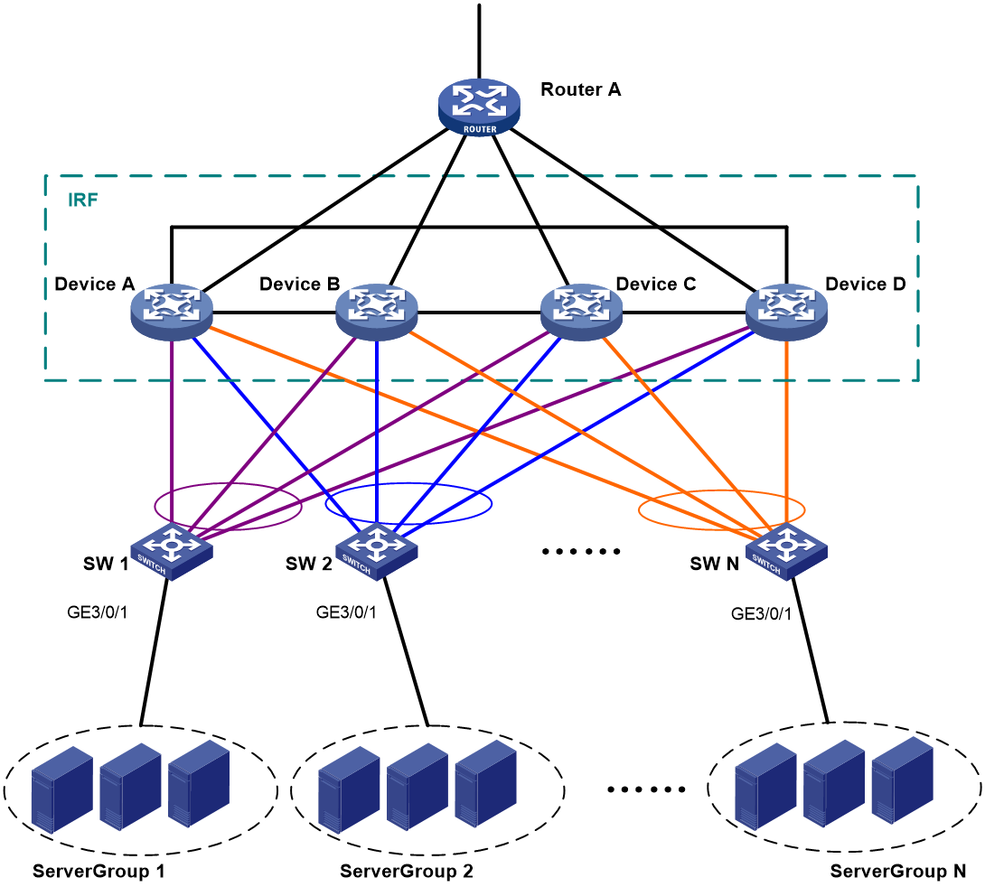
Table 2 through Table 4 show the VLAN and IP address assignment, IRF port bindings, and network topology scheme.
Table 2 VLAN and IP address assignment
|
Device |
VLAN interface |
IP address |
|
Router A |
VLAN-interface 41 |
172.24.41.2/24 |
|
Router A |
VLAN-interface 50 |
172.24.1.2/24 |
|
IRF fabric |
VLAN-interface 41 |
172.24.41.254/24 |
|
IRF fabric |
VLAN-interface 10 |
172.24.10.254/24 |
|
IRF fabric |
VLAN-interface 20 |
172.24.20.254/24 |
|
IRF fabric |
… |
… |
|
IRF fabric |
VLAN-interface N |
172.24.N.254/24 |
|
Device |
IRF port |
Neighboring IRF port |
IRF physical interfaces |
|
Device A |
IRF-port 1/1 |
IRF-port 4/2 |
XGE 1/2/0/4 |
|
Device A |
IRF-port 1/2 |
IRF-port 2/1 |
XGE 1/2/0/1 |
|
Device B |
IRF-port 2/1 |
IRF-port 1/2 |
XGE 2/4/0/2 |
|
Device B |
IRF-port 2/2 |
IRF-port 3/1 |
XGE 2/3/0/30 |
|
Device C |
IRF-port 3/1 |
IRF-port 2/2 |
XGE 3/3/0/15 |
|
Device C |
IRF-port 3/2 |
IRF-port 4/1 |
XGE 3/2/0/1 |
|
Device D |
IRF-port 4/1 |
IRF-port 3/2 |
XGE 4/6/0/4 |
|
Device D |
IRF-port 4/2 |
IRF-port 1/1 |
XGE 4/6/0/2 |
|
Device |
Neighboring device |
Port |
VLAN |
Aggregate interface |
|
IRF fabric |
SW 1 |
XGE 1/3/0/3 XGE 2/3/0/3 XGE 3/3/0/3 XGE 4/3/0/3 |
VLAN 10 |
Bridge-Aggregation 1 (LACP MAD) |
|
IRF fabric |
SW 2 |
XGE 1/3/0/4 XGE 2/3/0/4 XGE 3/3/0/4 XGE 4/3/0/4 |
VLAN 20 |
Bridge-Aggregation 2 |
|
IRF fabric |
Router A |
XGE 1/3/0/8 XGE 2/3/0/8 XGE 3/3/0/8 XGE 4/3/0/8 |
VLAN 41 |
Bridge-Aggregation 1024 |
|
SW 1 |
Server Group 1 |
GE 3/0/1 |
VLAN 10 |
N/A |
|
SW 1 |
IRF fabric |
XGE 2/0/21 XGE 2/0/22 XGE 2/0/23 XGE 2/0/24 |
VLAN 10 |
Bridge-Aggregation 1 (LACP MAD) |
|
SW 2 |
Server Group 2 |
GE 3/0/1 |
VLAN 20 |
N/A |
|
SW 2 |
IRF fabric |
XGE 2/0/21 XGE 2/0/22 XGE 2/0/23 XGE 2/0/24 |
VLAN 20 |
Bridge-Aggregation 1 |
|
Router A |
IRF fabric |
XGE 2/0/1 XGE 2/0/2 XGE 2/0/3 XGE 2/0/4 |
VLAN 41 |
Bridge-Aggregation 1 |
|
Router A |
Public network |
XGE 4/0/3 |
VLAN 50 |
N/A |
Analysis
For LACP MAD to run correctly, ensure that the intermediate device supports extended LACPDUs for LACP MAD.
To avoid single points of failure, use multichassis link aggregations to connect the IRF fabric to the downstream and upstream devices.
You do not need to run LACP MAD on all link aggregations. You can detect IRF split effectively by running LACP MAD on one dynamic link aggregation.
Restrictions and guidelines
When you configure LACP MAD on a link aggregation, follow these restrictions and guidelines:
· The link aggregation must use dynamic aggregation mode.
· The link aggregation must have a minimum of one member link from each member chassis.
· If the intermediate device is also an IRF fabric, you must assign the two IRF fabrics different domain IDs for correct split detection.
Procedures
Setting up the IRF fabric
1. Configure Device A:
# Assign member ID 1 to Device A.
<DeviceA> system-view
[DeviceA] irf member 1
# Bind Ten-GigabitEthernet 2/0/4 to IRF-port 1.
[DeviceA] irf-port 1
[DeviceA-irf-port1] port group interface ten-gigabitethernet 2/0/4
[DeviceA-irf-port1] quit
# Bind Ten-GigabitEthernet 2/0/1 to IRF-port 2.
[DeviceA] irf-port 2
[DeviceA-irf-port2] port group interface ten-gigabitethernet 2/0/1
[DeviceA-irf-port2] quit
# Save the running configuration.
[DeviceA] save
The current configuration will be written to the device. Are you sure? [Y/N]:y
Please input the file name(*.cfg)[cfa0:/irf.cfg]
(To leave the existing filename unchanged, press the enter key):
cfa0:/irf.cfg exists, overwrite? [Y/N]:y
Validating file. Please wait.....................................
Saved the current configuration to mainboard device successfully.
# Enable IRF mode.
[DeviceA] chassis convert mode irf
The device will switch to IRF mode and reboot. Continue? [Y/N]:y
You are recommended to save the current running configuration and specify the co
nfiguration file for the next startup. Continue? [Y/N]:y
Do you want to convert the content of the next startup configuration file cfa0:/
irf.cfg to make it available in stack mode? [Y/N]:y
Now rebooting, please wait...
Device A reboots to form a one-chassis IRF fabric.
2. Configure Device B:
# Assign member ID 2 to Device B.
<DeviceB> system-view
[DeviceB] irf member 2
# Bind Ten-GigabitEthernet 4/0/2 to IRF-port 1.
[DeviceB] irf-port 1
[DeviceB-irf-port1] port group interface ten-gigabitethernet 4/0/2
[DeviceB-irf-port1] quit
# Bind Ten-GigabitEthernet 3/0/30 to IRF-port 2.
[DeviceB] irf-port 2
[DeviceB-irf-port2] port group interface ten-gigabitethernet 3/0/30
[DeviceB-irf-port2] quit
# Save the running configuration.
[DeviceB] save
The current configuration will be written to the device. Are you sure? [Y/N]:y
Please input the file name(*.cfg)[cfa0:/irf.cfg]
(To leave the existing filename unchanged, press the enter key):
cfa0:/irf.cfg exists, overwrite? [Y/N]:y
Validating file. Please wait.....................................
Saved the current configuration to mainboard device successfully.
# Connect Device B to Device A, as shown in Figure 3.
# Enable IRF mode.
[DeviceB] chassis convert mode irf
The device will switch to IRF mode and reboot. Continue? [Y/N]:y
You are recommended to save the current running configuration and specify the co
nfiguration file for the next startup. Continue? [Y/N]:y
Do you want to convert the content of the next startup configuration file cfa0:/
irf.cfg to make it available in stack mode? [Y/N]:y
Now rebooting, please wait...
Device B reboots to join the IRF fabric. A two-chassis IRF fabric is formed.
3. Configure Device C:
# Assign member ID 3 to Device C.
<DeviceC> system-view
[DeviceC] irf member 3
# Bind Ten-GigabitEthernet 3/0/15 to IRF-port 1.
[DeviceC] irf-port 1
[DeviceC-irf-port1] port group interface ten-gigabitethernet 3/0/15
[DeviceC-irf-port1] quit
# Bind Ten-GigabitEthernet 2/0/1 to IRF-port 2.
[DeviceC] irf-port 2
[DeviceC-irf-port2] port group interface ten-gigabitethernet 2/0/1
[DeviceC-irf-port2] quit
# Save the running configuration.
[DeviceC] save
The current configuration will be written to the device. Are you sure? [Y/N]:y
Please input the file name(*.cfg)[cfa0:/irf.cfg]
(To leave the existing filename unchanged, press the enter key):
cfa0:/irf.cfg exists, overwrite? [Y/N]:y
Validating file. Please wait.....................................
Saved the current configuration to mainboard device successfully.
# Connect Device C to Device B, as shown in Figure 3.
# Enable IRF mode.
[DeviceC] chassis convert mode irf
The device will switch to IRF mode and reboot. Continue? [Y/N]:y
You are recommended to save the current running configuration and specify the co
nfiguration file for the next startup. Continue? [Y/N]:y
Do you want to convert the content of the next startup configuration file cfa0:/
irf.cfg to make it available in stack mode? [Y/N]:y
Now rebooting, please wait...
Device C reboots to join the IRF fabric. A three-chassis IRF fabric is formed.
4. Configure Device D:
# Assign member ID 4 to Device D.
<DeviceD> system-view
[DeviceD] irf member 4
# Bind Ten-GigabitEthernet 6/0/4 to IRF-port 1.
[DeviceD] irf-port 1
[DeviceD-irf-port1] port group interface ten-gigabitethernet 6/0/4
[DeviceD-irf-port1] quit
# Bind Ten-GigabitEthernet 6/0/2 to IRF-port 2.
[DeviceD] irf-port 2
[DeviceD-irf-port2] port group interface ten-gigabitethernet 6/0/2
[DeviceD-irf-port2] quit
# Save the running configuration.
[DeviceD] save
The current configuration will be written to the device. Are you sure? [Y/N]:y
Please input the file name(*.cfg)[cfa0:/irf.cfg]
(To leave the existing filename unchanged, press the enter key):
cfa0:/irf.cfg exists, overwrite? [Y/N]:y
Validating file. Please wait.....................................
Saved the current configuration to mainboard device successfully.
# Connect Device D to Device C and Device A, as shown in Figure 3.
# Enable IRF mode.
[DeviceD] chassis convert mode irf
The device will switch to IRF mode and reboot. Continue? [Y/N]:y
You are recommended to save the current running configuration and specify the co
nfiguration file for the next startup. Continue? [Y/N]:y
Do you want to convert the content of the next startup configuration file cfa0:/
irf.cfg to make it available in stack mode? [Y/N]:y
Now rebooting, please wait...
Device D reboots to join the IRF fabric. A four-chassis IRF fabric is formed.
Configuring software features
This example provides only basic software feature configuration.
Configuring the IRF fabric
After the IRF fabric is formed, the master's system name becomes the fabric's system name. You can configure software features on the fabric as you do on a standalone device.
1. Configure link aggregations:
# Create a Layer 2 dynamic aggregate interface Bridge-Aggregation 1. Enable LACP MAD on the aggregate interface.
<DeviceA> system-view
[DeviceA] interface bridge-aggregation 1
[DeviceA-Bridge-Aggregation1] link-aggregation mode dynamic
[DeviceA-Bridge-Aggregation1] mad enable
You need to assign a domain ID (range: 0-4294967295)
[Current domain is: 0]:
The assigned domain ID is: 0
[DeviceA-Bridge-Aggregation1] quit
# Assign the downlink ports that connect to SW 1 to the aggregation group of Bridge-Aggregation 1.
[DeviceA] interface range ten-gigabitethernet 1/3/0/3 ten-gigabitethernet 2/3/0/3 ten-gigabitethernet 3/3/0/3 ten-gigabitethernet 4/3/0/3
[DeviceA-if-range] port link-aggregation group 1
[DeviceA-if-range] quit
# Create Bridge-Aggregation 2. Assign the downlink ports that connect to SW 2 to the aggregation group.
[DeviceA] interface bridge-aggregation 2
[DeviceA-Bridge-Aggregation2] quit
[DeviceA] interface range ten-gigabitethernet 1/3/0/4 ten-gigabitethernet 2/3/0/4 ten-gigabitethernet 3/3/0/4 ten-gigabitethernet 4/3/0/4
[DeviceA-if-range] port link-aggregation group 2
[DeviceA-if-range] quit
# Create Bridge-Aggregation 1024. Assign the uplink ports that connect to Router A to the aggregation group.
[DeviceA] interface bridge-aggregation 1024
[DeviceA-Bridge-Aggregation1024] quit
[DeviceA] interface range ten-gigabitethernet 1/3/0/8 ten-gigabitethernet 2/3/0/8 ten-gigabitethernet 3/3/0/8 ten-gigabitethernet 4/3/0/8
[DeviceA-if-range] port link-aggregation group 1024
[DeviceA-if-range] quit
2. Configure VLANs, ports, and IP addresses:
# Create VLAN 10, assign an IP address to VLAN-interface 10, and assign Bridge-Aggregation 1 to VLAN 10.
[DeviceA] vlan 10
[DeviceA-vlan10] quit
[DeviceA] interface vlan-interface 10
[DeviceA-Vlan-interface10] ip address 172.24.10.254 24
[DeviceA-Vlan-interface10] quit
[DeviceA] interface bridge-aggregation 1
[DeviceA-Bridge-Aggregation1] port link-type trunk
[DeviceA-Bridge-Aggregation1] undo port trunk permit vlan 1
[DeviceA-Bridge-Aggregation1] port trunk permit vlan 10
[DeviceA-Bridge-Aggregation1] quit
# Create VLAN 20, assign an IP address to VLAN-interface 20, and assign Bridge-Aggregation 2 to VLAN 20.
[DeviceA] vlan 20
[DeviceA-vlan20] quit
[DeviceA] interface vlan-interface 20
[DeviceA-Vlan-interface20] ip address 172.24.20.254 24
[DeviceA-Vlan-interface20] quit
[DeviceA] interface bridge-aggregation 2
[DeviceA-Bridge-Aggregation2] port link-type trunk
[DeviceA-Bridge-Aggregation2] undo port trunk permit vlan 1
[DeviceA-Bridge-Aggregation2] port trunk permit vlan 20
[DeviceA-Bridge-Aggregation2] quit
# Create VLAN 41, assign an IP address to VLAN-interface 41, and assign Bridge-Aggregation 1024 to VLAN 41.
[DeviceA] vlan 41
[DeviceA-vlan41] quit
[DeviceA] interface vlan-interface 41
[DeviceA-Vlan-interface41] ip address 172.24.41.254 24
[DeviceA-Vlan-interface41] quit
[DeviceA] interface bridge-aggregation 1024
[DeviceA-Bridge-Aggregation1024] port access vlan 41
[DeviceA-Bridge-Aggregation1024] quit
3. Configure OSPF between the IRF fabric and Router A.
[DeviceA] interface loopback 0
[DeviceA-LoopBack0] ip address 172.24.254.1 255.255.255.255
[DeviceA-LoopBack0] quit
[DeviceA] ospf 1 router-id 172.24.254.1
[DeviceA-ospf-1] import-route direct
[DeviceA-ospf-1] area 0
[DeviceA-ospf-1-area-0.0.0.0] network 172.24.41.0 0.0.0.255
[DeviceA-ospf-1-area-0.0.0.0] quit
[DeviceA-ospf-1] quit
Configuring SW 1
1. Configure a link aggregation:
# Create Bridge-Aggregation 1, and enable the dynamic aggregation mode. You must enable the dynamic aggregation mode because this link aggregation will be used for LACP MAD.
<SW1> system-view
[SW1] interface bridge-aggregation 1
[SW1-Bridge-Aggregation1] link-aggregation mode dynamic
[SW1-Bridge-Aggregation1] quit
# Assign uplink ports to Bridge-Aggregation 1.
[SW1] interface range ten-gigabitethernet 2/0/21 to ten-gigabitethernet 2/0/24
[SW1-if-range] port link-aggregation group 1
[SW1-if-range] quit
2. Configure VLANs, ports, and IP addresses:
# Create all VLANs.
[SW1] vlan all
# Configure the aggregate interface that connects to the IRF fabric.
[SW1] interface bridge-aggregation 1
[SW1-Bridge-Aggregation1] port link-type trunk
[SW1-Bridge-Aggregation1] undo port trunk permit vlan 1
[SW1-Bridge-Aggregation1] port trunk permit vlan 10
[SW1-Bridge-Aggregation1] quit
# Configure the port that connects to Server Group 1.
[SW1] interface gigabitethernet 3/0/1
[SW1-GigabitEthernet3/0/1] port link-type trunk
[SW1-GigabitEthernet3/0/1] port trunk permit vlan all
[SW1-GigabitEthernet3/0/1] undo port trunk permit vlan 1
[SW1-GigabitEthernet3/0/1] quit
Configuring SW 2
1. Configure a link aggregation:
# Create Bridge-Aggregation 1.
<SW2> system-view
[SW2] interface bridge-aggregation 1
[SW2-Bridge-Aggregation1] quit
# Assign uplink ports to Bridge-Aggregation 1.
[SW2] interface range ten-gigabitethernet 2/0/21 to ten-gigabitethernet 2/0/24
[SW2-if-range] port link-aggregation group 1
[SW2-if-range] quit
2. Configure VLANs, ports, and IP addresses:
# Create all VLANs.
[SW2] vlan all
# Configure VLAN settings on the uplink aggregate interface that connects to the IRF fabric.
[SW2] interface bridge-aggregation 1
[SW2-Bridge-Aggregation1] port link-type trunk
[SW2-Bridge-Aggregation1] undo port trunk permit vlan 1
[SW2-Bridge-Aggregation1] port trunk permit vlan 20
[SW2-Bridge-Aggregation1] quit
# Configure VLAN settings on the port that connects to Server Group 2.
[SW2] interface gigabitethernet 3/0/1
[SW2-GigabitEthernet3/0/1] port link-type trunk
[SW2-GigabitEthernet3/0/1] port trunk permit vlan all
[SW2-GigabitEthernet3/0/1] undo port trunk permit vlan 1
[SW2-GigabitEthernet3/0/1] quit
Configuring Router A
In this example, the egress router configuration only includes the connection to the IRF fabric.
1. Configure link aggregation:
# Create Bridge-Aggregation 1.
<RouterA> system-view
[RouterA] interface bridge-aggregation 1
[RouterA-Bridge-Aggregation1] quit
# Assign the downlink ports that connect to the IRF fabric to Bridge-Aggregation 1.
[RouterA] interface range ten-gigabitethernet 2/0/1 to ten-gigabitethernet 2/0/4
[RouterA-if-range] port link-aggregation group 1
[RouterA-if-range] quit
2. Configure VLANs, ports, and IP addresses:
# Create VLAN 41, assign an IP address to VLAN-interface 41, and assign Bridge-Aggregation 1 to VLAN 41.
[RouterA] vlan 41
[RouterA-vlan41] quit
[RouterA] interface vlan-interface 41
[RouterA-vlan-interface41] ip address 172.24.41.2 24
[RouterA-vlan-interface41] quit
[RouterA] interface bridge-aggregation 1
[RouterA-Bridge-Aggregation1] port access vlan 41
[RouterA-Bridge-Aggregation1] quit
# Create VLAN 50, assign an IP address to VLAN-interface 50, and assign Ten-GigabitEthernet 4/0/3 to VLAN 50.
[RouterA] vlan 50
[RouterA-vlan50] quit
[RouterA] interface vlan-interface 50
[RouterA-vlan-interface50] ip address 172.24.1.2 24
[RouterA-vlan-interface50] quit
[RouterA] interface ten-gigabitethernet 4/0/3
[RouterA-Ten-GigabitEthernet4/0/3] port link-mode bridge
[RouterA-Ten-GigabitEthernet4/0/3] port access vlan 50
[RouterA-Ten-GigabitEthernet4/0/3] quit
3. Configure OSPF between the IRF fabric and Router A.
[RouterA] interface loopback 0
[RouterA-LoopBack0] ip addresss 172.24.254.2 255.255.255.255
[RouterA-LoopBack0] quit
[RouterA] ospf 1 router-id 172.24.254.2
[RouterA-ospf-1] import-route direct
[RouterA-ospf-1] area 0
[RouterA-ospf-1-area-0.0.0.0] network 172.24.41.0 0.0.0.255
[RouterA-ospf-1-area-0.0.0.0] quit
[RouterA-ospf-1] quit
Verifying the configuration
Verify the IRF and multichassis link aggregation configuration.
Verifying the IRF function
# Execute the display irf topology command.
<DeviceA> display irf topology
Topology Info
-------------------------------------------------------------------------
IRF-Port1 IRF-Port2
Switch Link neighbor Link neighbor Belong To
1 UP 4 UP 2 0210-fc01-0000
4 UP 3 UP 1 0210-fc01-0000
3 UP 2 UP 4 0210-fc01-0000
2 UP 1 UP 3 0210-fc01-0000
The output shows that all the IRF links are in UP state. The four-chassis IRF fabric is established.
Verifying the link backup function of multichassis aggregations
# Shut down Ten-GigabitEthernet 1/3/0/8, the port connected to Router A.
[DeviceA] interface ten-gigabitethernet 1/3/0/8
[DeviceA-Ten-GigabitEthernet1/3/0/8] shutdown
# Ping an IP address on the public network from a PC in Server Group 1.
C:\Users>ping 202.108.22.5 -t
Pinging 202.108.22.5 with 32 bytes of data:
Reply from 202.108.22.5: bytes=32 time=1ms TTL=122
Reply from 202.108.22.5: bytes=32 time=13ms TTL=122
Reply from 202.108.22.5: bytes=32 time<1ms TTL=122
Request timed out.
Request timed out.
Request timed out.
Reply from 202.108.22.5: bytes=32 time<1ms TTL=122
Reply from 202.108.22.5: bytes=32 time<1ms TTL=122
Reply from 202.108.22.5: bytes=32 time<1ms TTL=122
The output shows that the address can be pinged after transient traffic disruption.
# Bring up Ten-GigabitEthernet 1/3/0/8 and shut down Ten-GigabitEthernet 2/3/0/8.
[DeviceA-Ten-GigabitEthernet1/3/0/8] undo shutdown
[DeviceA-Ten-GigabitEthernet1/3/0/8] quit
[DeviceA] interface ten-gigabitethernet 2/3/0/8
[DeviceA-Ten-GigabitEthernet2/3/0/8] shutdown
# Ping the IP address on the public network from the PC.
C:\Users>ping 202.108.22.5 -t
Pinging 202.108.22.5 with 32 bytes of data:
Reply from 202.108.22.5: bytes=32 time=1ms TTL=122
Reply from 202.108.22.5: bytes=32 time=13ms TTL=122
Reply from 202.108.22.5: bytes=32 time<1ms TTL=122
Request timed out.
Request timed out.
Request timed out.
Reply from 202.108.22.5: bytes=32 time<1ms TTL=122
Reply from 202.108.22.5: bytes=32 time<1ms TTL=122
Reply from 202.108.22.5: bytes=32 time<1ms TTL=122
The output shows that the address can be pinged after transient traffic disruption.
Configuration files
· IRF fabric:
#
irf mac-address persistent always
irf auto-update enable
undo irf auto-merge enable
undo irf link-delay
irf member 1 priority 1
irf member 2 priority 1
irf member 3 priority 1
irf member 4 priority 1
#
ospf 1 router-id 172.24.254.1
import-route direct
area 0.0.0.0
network 172.24.41.0 0.0.0.255
#
vlan 10
#
vlan 20
#
vlan 13
#
vlan 41
#
irf-port 1/1
port group interface Ten-GigabitEthernet1/2/0/4 mode enhanced
#
irf-port 1/2
port group interface Ten-GigabitEthernet1/2/0/1 mode enhanced
#
irf-port 2/1
port group interface Ten-GigabitEthernet2/4/0/2 mode enhanced
#
irf-port 2/2
port group interface Ten-GigabitEthernet2/3/0/30 mode enhanced
#
irf-port 3/1
port group interface Ten-GigabitEthernet3/3/0/15 mode enhanced
#
irf-port 3/2
port group interface Ten-GigabitEthernet3/2/0/1 mode enhanced
#
irf-port 4/1
port group interface Ten-GigabitEthernet4/6/0/4 mode enhanced
#
irf-port 4/2
port group interface Ten-GigabitEthernet4/6/0/2 mode enhanced
#
interface bridge-aggregation 1
port link-type trunk
undo port trunk permit vlan 1
port trunk permit vlan 10
mad enable
link-aggregation mode dynamic
#
interface bridge-aggregation 2
port link-type trunk
undo port trunk permit vlan 1
port trunk permit vlan 20
#
interface bridge-aggregation 1024
port access vlan 41
#
interface loopback 0
ip address 172.24.254.1 255.255.255.255
#
interface vlan-interface 10
ip address 172.24.10.254 24
#
interface vlan-interface 20
ip address 172.24.20.254 24
#
interface vlan-interface 41
ip address 172.24.41.254 24
#
interface Ten-GigabitEthernet 1/3/0/3
port link-mode bridge
port link-type trunk
undo port trunk permit vlan 1
port trunk permit vlan 10
port link-aggregation group 1
#
interface Ten-GigabitEthernet 1/3/0/4
port link-mode bridge
port link-type trunk
undo port trunk permit vlan 1
port trunk permit vlan 20
port link-aggregation group 2
#
interface Ten-GigabitEthernet 1/3/0/8
port link-mode bridge
port access vlan 41
port link-aggregation group 1024
#
interface Ten-GigabitEthernet 2/3/0/3
port link-mode bridge
port link-type trunk
undo port trunk permit vlan 1
port trunk permit vlan 10
port link-aggregation group 1
#
interface Ten-GigabitEthernet 2/3/0/4
port link-mode bridge
port link-type trunk
undo port trunk permit vlan 1
port trunk permit vlan 20
port link-aggregation group 2
#
interface Ten-GigabitEthernet 2/3/0/8
port link-mode bridge
port access vlan 41
port link-aggregation group 1024
#
interface Ten-GigabitEthernet 3/3/0/3
port link-mode bridge
port link-type trunk
undo port trunk permit vlan 1
port trunk permit vlan 10
port link-aggregation group 1
#
interface Ten-GigabitEthernet 3/3/0/4
port link-mode bridge
port link-type trunk
undo port trunk permit vlan 1
port trunk permit vlan 20
port link-aggregation group 2
#
interface Ten-GigabitEthernet 3/3/0/8
port link-mode bridge
port access vlan 41
port link-aggregation group 1024
#
interface Ten-GigabitEthernet 4/3/0/3
port link-mode bridge
port link-type trunk
undo port trunk permit vlan 1
port trunk permit vlan 10
port link-aggregation group 1
#
interface Ten-GigabitEthernet 4/3/0/4
port link-mode bridge
port link-type trunk
undo port trunk permit vlan 1
port trunk permit vlan 20
port link-aggregation group 2
#
interface Ten-GigabitEthernet 4/3/0/8
port link-mode bridge
port access vlan 41
port link-aggregation group 1024
#
· SW 1:
#
vlan 1
#
vlan 2 to 4094
#
interface gigabitethernet 3/0/1
port link-mode bridge
port link-type trunk
undo port trunk permit vlan 1
port trunk permit vlan 2 to 4094
#
interface bridge-aggregation 1
port link-type trunk
undo port trunk permit vlan 1
port trunk permit vlan 10
link-aggregation mode dynamic
#
interface Ten-GigabitEthernet 2/0/21
port link-mode bridge
port link-type trunk
undo port trunk permit vlan 1
port trunk permit vlan 10
port link-aggregation group 1
#
interface Ten-GigabitEthernet 2/0/22
port link-mode bridge
port link-type trunk
undo port trunk permit vlan 1
port trunk permit vlan 10
port link-aggregation group 1
#
interface Ten-GigabitEthernet 2/0/23
port link-mode bridge
port link-type trunk
undo port trunk permit vlan 1
port trunk permit vlan 10
port link-aggregation group 1
#
interface Ten-GigabitEthernet 2/0/24
port link-mode bridge
port link-type trunk
undo port trunk permit vlan 1
port trunk permit vlan 10
port link-aggregation group 1
#
· SW 2:
#
vlan 1
#
vlan 2 to 4094
#
interface gigabitethernet 3/0/1
port link-mode bridge
port link-type trunk
undo port trunk permit vlan 1
port trunk permit vlan 2 to 4094
#
interface bridge-aggregation 1
port link-type trunk
undo port trunk permit vlan 1
port trunk permit vlan 20
#
interface Ten-GigabitEthernet 2/0/21
port link-mode bridge
port link-type trunk
undo port trunk permit vlan 1
port trunk permit vlan 20
port link-aggregation group 1
#
interface Ten-GigabitEthernet 2/0/22
port link-mode bridge
port link-type trunk
undo port trunk permit vlan 1
port trunk permit vlan 20
port link-aggregation group 1
#
interface Ten-GigabitEthernet 2/0/23
port link-mode bridge
port link-type trunk
undo port trunk permit vlan 1
port trunk permit vlan 20
port link-aggregation group 1
#
interface Ten-GigabitEthernet 2/0/24
port link-mode bridge
port link-type trunk
undo port trunk permit vlan 1
port trunk permit vlan 20
port link-aggregation group 1
#
· Router A:
#
ospf 1 router-id 172.24.254.2
import-route direct
area 0.0.0.0
network 172.24.41.0 0.0.0.255
#
vlan 41
#
vlan 50
#
interface bridge-aggregation 1
port access vlan 41
#
interface loopback 0
ip address 172.24.254.2 255.255.255.255
#
interface vlan-interface 41
ip address 172.24.41.2 24
#
interface vlan-interface 50
ip address 172.24.1.2 24
#
interface Ten-GigabitEthernet 2/0/1
port link-mode bridge
port access vlan 41
port link-aggregation group 1
#
interface Ten-GigabitEthernet 2/0/2
port link-mode bridge
port access vlan 41
port link-aggregation group 1
#
interface Ten-GigabitEthernet 2/0/3
port link-mode bridge
port access vlan 41
port link-aggregation group 1
#
interface Ten-GigabitEthernet 2/0/4
port link-mode bridge
port access vlan 41
port link-aggregation group 1
#
interface Ten-GigabitEthernet 2/0/12
port link-mode bridge
port access vlan 50
#
Example: Upgrading a two-chassis IRF fabric to a four-chassis IRF fabric (BFD MAD)
Network configuration
Upgrade a two-chassis IRF fabric (see Figure 4) to a four-chassis IRF fabric (see Figure 6) by performing one of the following tasks:
· Merge two two-chassis IRF fabrics.
· Add two chassis to the existing two-chassis IRF fabric.
Configure BFD MAD on the four-chassis IRF fabric, and set up a BFD MAD link between the intermediate device and each member device.
Figure 4 Two-chassis IRF fabric
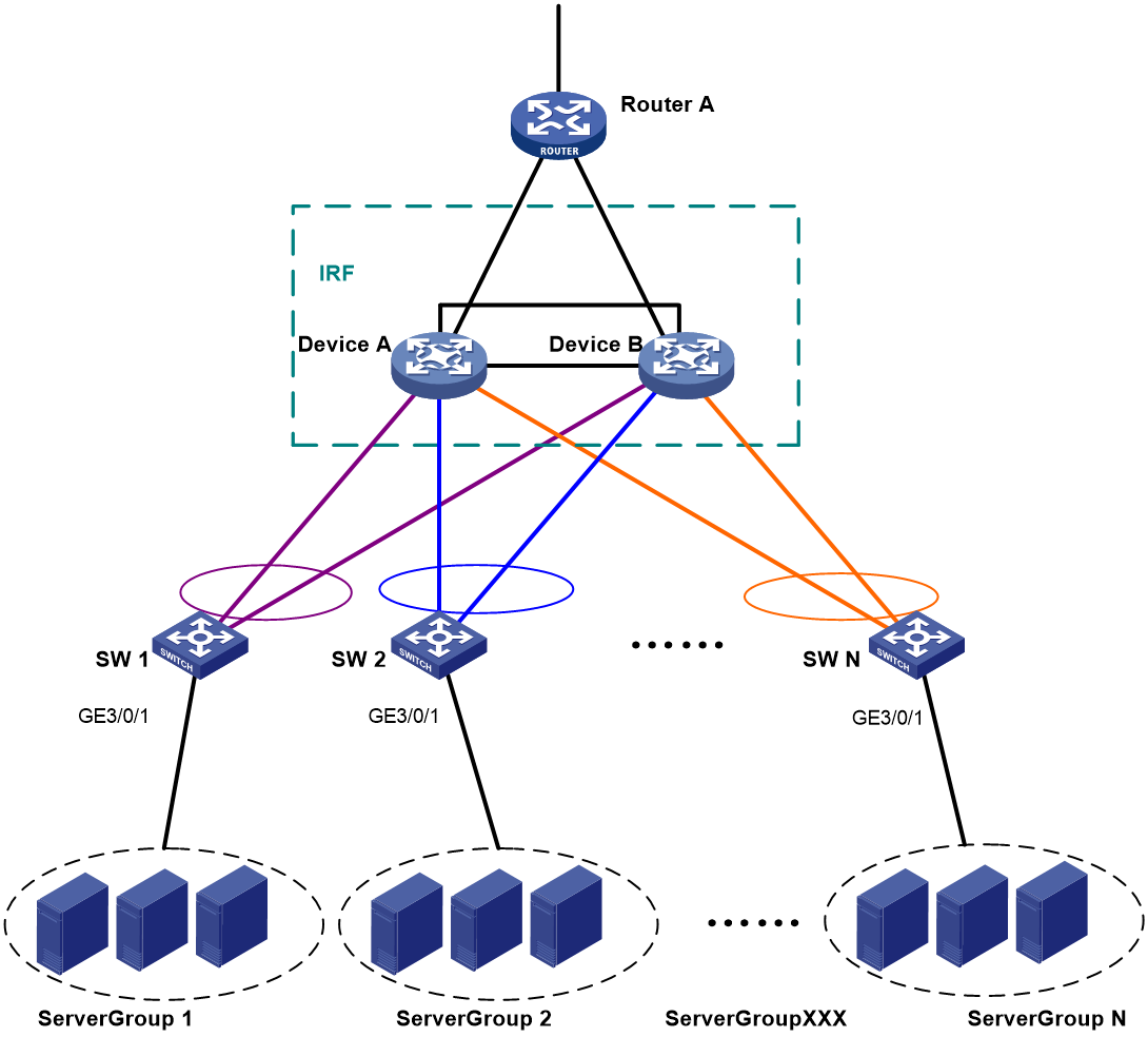
Figure 5 Upgrading the two-chassis IRF fabric to a four-chassis IRF fabric
Figure 6 BFD MAD-enabled four-chassis IRF fabric
Table 5 Network topology (partial)
|
Device |
Neighboring device |
Port |
VLAN |
|
IRF fabric |
Layer 2 switch |
XGE 1/3/0/1 XGE 2/3/0/1 XGE 3/3/0/1 XGE 4/3/0/1 |
VLAN 13 (BFD MAD VLAN) |
|
Layer 2 switch |
IRF fabric |
XGE 1/0/41 XGE 1/0/42 XGE 1/0/43 XGE 1/0/44 |
VLAN 13 |
For more information about the VLAN and IP assignment, port bindings, and network topology scheme, see Table 2, Table 3, and Table 4.
Analysis
Because each IRF member must have a unique member ID on the IRF fabric, you must verify that the member ID assignment schemes of the two IRF fabrics do not conflict. If the schemes conflict, renumber the member devices in one IRF fabric to ensure that the two IRF fabrics can merge.
To avoid single points of failure, use multichassis link aggregations to connect the IRF fabric to the downstream and upstream devices.
If a downstream or upstream device can process extended LACPDUs for LACP MAD, you can use LACP MAD for IRF split detection. If none of the upstream or downstream devices can process extended LACPDUs, you can use BFD MAD instead.
You can deploy BFD MAD by using the following methods:
· Connect all member chassis with dedicated BFD MAD links into a full mesh topology. This method is suitable for two-chassis IRF fabrics.
· Set up a dedicated BFD MAD link with an intermediate device for each IRF member chassis. This method is suitable for three- or four-chassis IRF fabrics because it uses fewer physical ports than the previous method.
The intermediate device forwards BFD MAD packets transparently. You must assign all BFD MAD links to the VLAN used for BFD MAD.
Restrictions and guidelines
When you configure BFD MAD, follow these restrictions and guidelines:
|
Category |
Restrictions and guidelines |
|
VLAN |
· Do not enable BFD MAD on VLAN-interface 1. · Do not use the BFD MAD VLAN for any purpose other than configuring BFD MAD. No Layer 2 or Layer 3 features, including ARP and LACP, can work on the BFD MAD-enabled VLAN interface or any port in the VLAN. If you configure any other feature on the VLAN, neither the configured feature nor the BFD MAD feature can work correctly. · If an intermediate device is used, assign the ports of BFD MAD links to the BFD MAD VLAN on the device. · The IRF fabrics in a network must use different BFD MAD VLANs. |
|
MAD IP address |
· To avoid problems, only use the mad ip address command to configure IP addresses on the BFD MAD-enabled VLAN interface. For example, an IP address configured with the ip address command or a VRRP virtual IP address can cause problems. · All MAD IP addresses on the BFD MAD-enabled VLAN interface must be on the same subnet. |
|
Feature compatibility |
· Disable the spanning tree feature on any port in the BFD MAD VLAN. The MAD feature is mutually exclusive with the spanning tree feature. · Do not bind a BFD MAD-enabled VLAN interface to a VPN instance. The MAD feature is mutually exclusive with VPN. |
Procedures
Use one of the following methods to upgrade a two-chassis IRF fabric to a four-chassis IRF fabric:
· Adding two chassis to a two-chassis IRF fabric
· Merging two two-chassis IRF fabrics
Adding two chassis to a two-chassis IRF fabric
1. Configure the IRF fabric:
# Bind Ten-GigabitEthernet 1/2/0/4 to IRF-port 1/1.
<DeviceA> system-view
[DeviceA] interface ten-gigabitethernet 1/2/0/4
[DeviceA-Ten-GigabitEthernet1/2/0/4] shutdown
[DeviceA-Ten-GigabitEthernet1/2/0/4] quit
[DeviceA] irf-port 1/1
[DeviceA-irf-port1/1] port group interface ten-gigabitethernet 1/2/0/4
[DeviceA-irf-port1/1] quit
[DeviceA] interface ten-gigabitethernet 1/2/0/4
[DeviceA-Ten-GigabitEthernet1/2/0/4] undo shutdown
[DeviceA-Ten-GigabitEthernet1/2/0/4] quit
# Bind Ten-GigabitEthernet 2/3/0/30 to IRF-port 2/2.
[DeviceA] interface ten-gigabitethernet 2/3/0/30
[DeviceA-Ten-GigabitEthernet2/3/0/30] shutdown
[DeviceA-Ten-GigabitEthernet2/3/0/30] quit
[DeviceA] irf-port 2/2
[DeviceA-irf-port2/2] port group interface ten-gigabitethernet 2/3/0/30
[DeviceA-irf-port2/2] quit
[DeviceA] interface ten-gigabitethernet 2/3/0/30
[DeviceA-Ten-GigabitEthernet2/3/0/30] undo shutdown
[DeviceA-Ten-GigabitEthernet2/3/0/30] quit
# Save the configuration.
[DeviceA] save
The current configuration will be written to the device. Are you sure? [Y/N]:y
Please input the file name(*.cfg)[cfa0:/irf.cfg]
(To leave the existing filename unchanged, press the enter key):
cfa0:/irf.cfg exists, overwrite? [Y/N]:y
Validating file. Please wait.....................................
Saved the current configuration to mainboard device successfully.
# Activate the IRF port configuration.
[DeviceA] irf-port-configuration active
2. Configure IRF on Device C:
# Assign member ID 3 to Device C.
<DeviceC> system-view
[DeviceC] irf member 3
# Bind Ten-GigabitEthernet 3/0/15 to IRF-port 1.
[DeviceC] irf-port 1
[DeviceC-irf-port1] port group interface ten-gigabitethernet 3/0/15
[DeviceC-irf-port1] quit
# Bind Ten-GigabitEthernet 2/0/1 to IRF-port 2.
[DeviceC] irf-port 2
[DeviceC-irf-port2] port group interface ten-gigabitethernet 2/0/1
[DeviceC-irf-port2] quit
# Save the configuration.
[DeviceC] save
The current configuration will be written to the device. Are you sure? [Y/N]:y
Please input the file name(*.cfg)[cfa0:/irf.cfg]
(To leave the existing filename unchanged, press the enter key):
cfa0:/irf.cfg exists, overwrite? [Y/N]:y
Validating file. Please wait.....................................
Saved the current configuration to mainboard device successfully.
# Connect Device C to Device B, as shown in Figure 6.
# Enable IRF mode.
[DeviceC] chassis convert mode irf
The device will switch to IRF mode and reboot. Continue? [Y/N]:y
You are recommended to save the current running configuration and specify the co
nfiguration file for the next startup. Continue? [Y/N]:y
Do you want to convert the content of the next startup configuration file cfa0:/
irf.cfg to make it available in stack mode? [Y/N]:y
Now rebooting, please wait...
Device C reboots to join the IRF fabric. A three-chassis IRF fabric is formed.
3. Configure IRF on Device D:
# Assign member ID 4 to Device D.
<DeviceD> system-view
[DeviceD] irf member 4
# Bind Ten-GigabitEthernet 6/0/4 to IRF-port 1.
[DeviceD] irf-port 1
[DeviceD-irf-port1] port group interface ten-gigabitethernet 6/0/4
[DeviceD-irf-port1] quit
# Bind Ten-GigabitEthernet 6/0/2 to IRF-port 2.
[DeviceD] irf-port 2
[DeviceD-irf-port2] port group interface ten-gigabitethernet 6/0/2
[DeviceD-irf-port2] quit
# Save the configuration.
[DeviceD] save
The current configuration will be written to the device. Are you sure? [Y/N]:y
Please input the file name(*.cfg)[cfa0:/irf.cfg]
(To leave the existing filename unchanged, press the enter key):
cfa0:/irf.cfg exists, overwrite? [Y/N]:y
Validating file. Please wait.....................................
Saved the current configuration to mainboard device successfully.
# Connect Device D to Device A and Device C, as shown in Figure 6.
# Enable IRF mode.
[DeviceD] chassis convert mode irf
The device will switch to IRF mode and reboot. Continue? [Y/N]:y
You are recommended to save the current running configuration and specify the co
nfiguration file for the next startup. Continue? [Y/N]:y
Do you want to convert the content of the next startup configuration file cfa0:/
irf.cfg to make it available in stack mode? [Y/N]:y
Now rebooting, please wait...
Device D reboots to join the IRF fabric. A four-chassis IRF fabric is formed.
Merging two two-chassis IRF fabrics
1. Configure the IRF fabric that has Device A and Device B:
# Bind Ten-GigabitEthernet 1/2/0/4 to IRF-port 1/1.
<DeviceA> system-view
[DeviceA] interface ten-gigabitethernet 1/2/0/4
[DeviceA-Ten-GigabitEthernet1/2/0/4] shutdown
[DeviceA-Ten-GigabitEthernet1/2/0/4] quit
[DeviceA] irf-port 1/1
[DeviceA-irf-port1/1] port group interface ten-gigabitethernet 1/2/0/4
[DeviceA-irf-port1/1] quit
[DeviceA] interface ten-gigabitethernet 1/2/0/4
[DeviceA-Ten-GigabitEthernet1/2/0/4] undo shutdown
[DeviceA-Ten-GigabitEthernet1/2/0/4] quit
# Bind Ten-GigabitEthernet 2/3/0/30 to IRF-port 2/2.
[DeviceA] interface ten-gigabitethernet 2/3/0/30
[DeviceA-Ten-GigabitEthernet2/3/0/30] shutdown
[DeviceA-Ten-GigabitEthernet2/3/0/30] quit
[DeviceA] irf-port 2/2
[DeviceA-irf-port2/2] port group interface ten-gigabitethernet 2/3/0/30
[DeviceA-irf-port2/2] quit
[DeviceA] interface ten-gigabitethernet 2/3/0/30
[DeviceA-Ten-GigabitEthernet2/3/0/30] undo shutdown
[DeviceA-Ten-GigabitEthernet2/3/0/30] quit
# Save the running configuration.
[DeviceA] save
The current configuration will be written to the device. Are you sure? [Y/N]:y
Please input the file name(*.cfg)[cfa0:/irf.cfg]
(To leave the existing filename unchanged, press the enter key):
cfa0:/irf.cfg exists, overwrite? [Y/N]:y
Validating file. Please wait.....................................
Saved the current configuration to mainboard device successfully.
2. Configure the IRF fabric that has Device C and Device D:
# Change the member IDs to 3 and 4 for Device C and Device D, respectively.
<DeviceC> system-view
[DeviceC] irf member 1 renumber 3
Renumbering the member ID may result in configuration change or loss. Continue?[
Y/N]y
[DeviceC] irf member 2 renumber 4
Renumbering the member ID may result in configuration change or loss. Continue?[
Y/N]y
# Save the running configuration and reboot the IRF fabric.
[DeviceC] quit
<DeviceC> reboot
Start to check configuration with next startup configuration file, please wait..
.......DONE!
Current configuration may be lost after the reboot, save current configuration?
[Y/N]:y
Please input the file name(*.cfg)[ cfa0:/irf.cfg]
(To leave the existing filename unchanged, press the enter key):
This command will reboot the device. Continue? [Y/N]:y
# Bind Ten-GigabitEthernet 3/3/0/15 to IRF-port 3/1.
<DeviceC> system-view
[DeviceC] interface ten-gigabitethernet 3/3/0/15
[DeviceC-Ten-GigabitEthernet3/3/0/15] shutdown
[DeviceC-Ten-GigabitEthernet3/3/0/15] quit
[DeviceC] irf-port 3/1
[DeviceC-irf-port3/1] port group interface ten-gigabitethernet 3/3/0/15
[DeviceC-irf-port3/1] quit
[DeviceC] interface ten-gigabitethernet 3/3/0/15
[DeviceC-Ten-GigabitEthernet3/3/0/15] undo shutdown
[DeviceC-Ten-GigabitEthernet3/3/0/15] quit
# Bind Ten-GigabitEthernet 4/6/0/2 to IRF-port 4/2.
[DeviceC] interface ten-gigabitethernet 4/6/0/2
[DeviceC-Ten-GigabitEthernet4/6/0/2] shutdown
[DeviceC-Ten-GigabitEthernet4/6/0/2] quit
[DeviceC] irf-port 4/2
[DeviceC-irf-port4/2] port group interface ten-gigabitethernet4/6/0/2
[DeviceC-irf-port4/2] quit
[DeviceC] interface ten-gigabitethernet 4/6/0/2
[DeviceC-Ten-GigabitEthernet4/6/0/2] undo shutdown
[DeviceC-Ten-GigabitEthernet4/6/0/2] quit
# Save the configuration.
[DeviceC] save
The current configuration will be written to the device. Are you sure? [Y/N]:y
Please input the file name(*.cfg)[cfa0:/irf.cfg]
(To leave the existing filename unchanged, press the enter key):
cfa0:/irf.cfg exists, overwrite? [Y/N]:y
Validating file. Please wait.....................................
Saved the current configuration to mainboard device successfully.
# Connect Device C to Device B, and connect Device A to Device D, as shown in Figure 6.
The two IRF fabrics perform master election. The one that lost the master election reboots to join the IRF fabric. A four-chassis IRF fabric is formed.
Configuring software features
This example provides only basic software feature configuration.
Configuring the IRF fabric
After the IRF fabric is formed, the master's system name becomes the fabric's system name. You can configure software features on the fabric as you do on a standalone device.
|
|
NOTE: In this example, the feature settings on the original IRF fabrics were cleared. In practice, you do not need to reconfigure all settings you have configured, such as IP addresses. |
1. Configure link aggregations:
# Create Bridge-Aggregation 1.
<DeviceA> system-view
[DeviceA] interface bridge-aggregation 1
[DeviceA-Bridge-Aggregation1] quit
# Assign the downlink ports that connect to SW 1 to Bridge-Aggregation 1.
[DeviceA] interface range ten-gigabitethernet 1/3/0/3 ten-gigabitethernet 2/3/0/3 ten-gigabitethernet 3/3/0/3 ten-gigabitethernet 4/3/0/3
[DeviceA-if-range] port link-aggregation group 1
[DeviceA-if-range] quit
# Create Bridge-Aggregation 2.
[DeviceA] interface bridge-aggregation 2
[DeviceA-Bridge-Aggregation2] quit
# Assign the downlink ports that connect to SW 2 to Bridge-Aggregation 2.
[DeviceA] interface range ten-gigabitethernet 1/3/0/4 ten-gigabitethernet 2/3/0/4 ten-gigabitethernet 3/3/0/4 ten-gigabitethernet 4/3/0/4
[DeviceA-if-range] port link-aggregation group 2
[DeviceA-if-range] quit
# Create Bridge-Aggregation 1024. Assign the uplink ports that connect to Router A to the aggregation group.
[DeviceA] interface bridge-aggregation 1024
[DeviceA-Bridge-Aggregation1024] quit
[DeviceA] interface range ten-gigabitethernet 1/3/0/8 ten-gigabitethernet 2/3/0/8 ten-gigabitethernet 3/3/0/8 ten-gigabitethernet 4/3/0/8
[DeviceA-if-range] port link-aggregation group 1024
[DeviceA-if-range] quit
2. Configure BFD MAD:
# Create VLAN 13, and enable BFD MAD on VLAN-interface 13.
[DeviceA] vlan 13
[DeviceA-vlan13] quit
[DeviceA] interface Vlan-interface 13
[DeviceA-Vlan-interface13] mad bfd enable
# Configure a MAD IP address for each member device on VLAN-interface 13.
[DeviceA-Vlan-interface13] mad ip address 172.1.1.1 24 member 1
[DeviceA-Vlan-interface13] mad ip address 172.1.1.2 24 member 2
[DeviceA-Vlan-interface13] mad ip address 172.1.1.3 24 member 3
[DeviceA-Vlan-interface13] mad ip address 172.1.1.4 24 member 4
[DeviceA-Vlan-interface13] undo shutdown
[DeviceA-Vlan-interface13] quit
# Assign the ports that connect to the Layer 2 switch to VLAN 13. Disable the spanning tree feature on the ports.
[DeviceA] interface range ten-gigabitethernet 1/3/0/1 ten-gigabitethernet 2/3/0/1 ten-gigabitethernet 3/3/0/1 ten-gigabitethernet 4/3/0/1
[DeviceA-if-range] undo stp enable
[DeviceA-if-range] port access vlan 13
[DeviceA-if-range] quit
3. Configure VLANs, ports, and IP addresses:
# Create VLAN 10, assign an IP address to VLAN-interface 10, and assign Bridge-Aggregation 1 to VLAN 10.
[DeviceA] vlan 10
[DeviceA-vlan10] quit
[DeviceA] interface vlan-interface 10
[DeviceA-Vlan-interface10] ip address 172.24.10.254 24
[DeviceA-Vlan-interface10] quit
[DeviceA] interface bridge-aggregation 1
[DeviceA-Bridge-Aggregation1] port link-type trunk
[DeviceA-Bridge-Aggregation1] undo port trunk permit vlan 1
[DeviceA-Bridge-Aggregation1] port trunk permit vlan 10
[DeviceA-Bridge-Aggregation1] quit
# Create VLAN 20, assign an IP address to VLAN-interface 20, and assign Bridge-Aggregation 2 to VLAN 20.
[DeviceA] vlan 20
[DeviceA-vlan20] quit
[DeviceA] interface vlan-interface 20
[DeviceA-Vlan-interface20] ip address 172.24.20.254 24
[DeviceA-Vlan-interface20] quit
[DeviceA] interface bridge-aggregation 2
[DeviceA-Bridge-Aggregation2] port link-type trunk
[DeviceA-Bridge-Aggregation2] undo port trunk permit vlan 1
[DeviceA-Bridge-Aggregation2] port trunk permit vlan 20
[DeviceA-Bridge-Aggregation2] quit
# Create VLAN 41, assign an IP address to VLAN-interface 41, and assign Bridge-Aggregation 1024 to VLAN 41.
[DeviceA] vlan 41
[DeviceA-vlan41] quit
[DeviceA] interface vlan-interface 41
[DeviceA-Vlan-interface41] ip address 172.24.41.254 24
[DeviceA-Vlan-interface41] quit
[DeviceA] interface bridge-aggregation 1024
[DeviceA-Bridge-Aggregation1024] port access vlan 41
[DeviceA-Bridge-Aggregation1024] quit
4. Configure OSPF between the IRF fabric and Router A.
[DeviceA] interface loopback 0
[DeviceA-LoopBack0] ip address 172.24.254.1 255.255.255.255
[DeviceA-LoopBack0] quit
[DeviceA] ospf 1 router-id 172.24.254.1
[DeviceA-ospf-1] import-route direct
[DeviceA-ospf-1] area 0
[DeviceA-ospf-1-area-0.0.0.0] network 172.24.41.0 0.0.0.255
[DeviceA-ospf-1-area-0.0.0.0] quit
[DeviceA-ospf-1] quit
Configuring SW 1
1. Configure a link aggregation:
# Create Bridge-Aggregation 1.
<SW1> system-view
[SW1] interface bridge-aggregation 1
[SW1-Bridge-Aggregation1] quit
# Assign uplink ports to Bridge-Aggregation 1.
[SW1] interface range ten-gigabitethernet 2/0/21 to ten-gigabitethernet 2/0/24
[SW1-if-range] port link-aggregation group 1
[SW1-if-range] quit
2. Configure VLANs, ports, and IP addresses:
# Create all VLANs.
[SW1] vlan all
# Configure VLAN settings on Bridge-Aggregation 1.
[SW1] interface bridge-aggregation 1
[SW1-Bridge-Aggregation1] port link-type trunk
[SW1-Bridge-Aggregation1] undo port trunk permit vlan 1
[SW1-Bridge-Aggregation1] port trunk permit vlan 10
[SW1-Bridge-Aggregation1] quit
# Configure VLAN settings for the port that connects to Server Group 1.
[SW1] interface gigabitethernet 3/0/1
[SW1-GigabitEthernet3/0/1] port link-type trunk
[SW1-GigabitEthernet3/0/1] port trunk permit vlan all
[SW1-GigabitEthernet3/0/1] undo port trunk permit vlan 1
[SW1-GigabitEthernet3/0/1] quit
Configuring SW 2
1. Configure a link aggregation:
# Create Bridge-Aggregation 1.
<SW2> system-view
[SW2] interface bridge-aggregation 1
[SW2-Bridge-Aggregation1] quit
# Assign uplink ports to Bridge-Aggregation 1.
[SW2] interface range ten-gigabitethernet 2/0/21 to ten-gigabitethernet 2/0/24
[SW2-if-range] port link-aggregation group 1
[SW2-if-range] quit
2. Configure VLANs, ports, and IP addresses:
# Create all VLANs.
[SW2] vlan all
# Configure VLAN settings on Bridge-Aggregation 1.
[SW2] interface bridge-aggregation 1
[SW2-Bridge-Aggregation1] port link-type trunk
[SW2-Bridge-Aggregation1] undo port trunk permit vlan 1
[SW2-Bridge-Aggregation1] port trunk permit vlan 20
[SW2-Bridge-Aggregation1] quit
# Configure the port that connects to Server Group 2.
[SW2] interface gigabitethernet 3/0/1
[SW2-GigabitEthernet3/0/1] port link-type trunk
[SW2-GigabitEthernet3/0/1] port trunk permit vlan all
[SW2-GigabitEthernet3/0/1] undo port trunk permit vlan 1
[SW2-GigabitEthernet3/0/1] quit
Configring the Layer 2 switch
# Create VLAN 13.
<L2Switch> system-view
[L2Switch] vlan 13
[L2Switch-vlan13] quit
# Assign the ports used for BFD MAD to VLAN 13.
[L2Switch] interface range ten-gigabitethernet 1/0/41 to ten-gigabitethernet 1/0/44
[L2Switch-if-range] port access vlan 13
[L2Switch-if-range] quit
Configuring Router A
In this example, the egress router configuration only includes the connection to the IRF fabric.
1. Configure link aggregation:
# Create Bridge-Aggregation 1.
<RouterA> system-view
[RouterA] interface bridge-aggregation 1
[RouterA-Bridge-Aggregation1] quit
# Assign the downlink ports that connect to the IRF fabric to Bridge-Aggregation 1.
[RouterA] interface range ten-gigabitethernet 2/0/1 to ten-gigabitethernet 2/0/4
[RouterA-if-range] port link-aggregation group 1
[RouterA-if-range] quit
2. Configure VLANs, ports, and IP addresses:
# Create VLAN 41, assign an IP address to VLAN-interface 41, and assign Bridge-Aggregation 1 to VLAN 41.
[RouterA] vlan 41
[RouterA-vlan41] quit
[RouterA] interface vlan-interface 41
[RouterA-vlan-interface41] ip address 172.24.41.2 24
[RouterA-vlan-interface41] quit
[RouterA] interface bridge-aggregation 1
[RouterA-Bridge-Aggregation1] port access vlan 41
[RouterA-Bridge-Aggregation1] quit
# Create VLAN 50, assign an IP address to VLAN-interface 50, and assign Ten-GigabitEthernet4/0/3 to VLAN 50.
[RouterA] vlan 50
[RouterA-vlan50] quit
[RouterA] interface vlan-interface 50
[RouterA-vlan-interface50] ip address 172.24.1.2 24
[RouterA-vlan-interface50] quit
[RouterA] interface ten-gigabitethernet 4/0/3
[RouterA-Ten-GigabitEthernet4/0/3] port link-mode bridge
[RouterA-Ten-GigabitEthernet4/0/3] port access vlan 50
[RouterA-Ten-GigabitEthernet4/0/3] quit
3. Configure OSPF between the router and the IRF fabric.
[RouterA] interface loopback 0
[RouterA-LoopBack0] ip address 172.24.254.2 255.255.255.255
[RouterA-LoopBack0] quit
[RouterA] ospf 1 router-id 172.24.254.2
[RouterA-ospf-1] import-route direct
[RouterA-ospf-1] area 0
[RouterA-ospf-1-area-0.0.0.0] network 172.24.41.0 0.0.0.255
[RouterA-ospf-1-area-0.0.0.0] quit
[RouterA-ospf-1] quit
Verifying the configuration
Verify the IRF and multichassis link aggregation configuration.
Verifying the IRF function
# Execute the display irf topology command.
<DeviceA> display irf topology
Topology Info
-------------------------------------------------------------------------
IRF-Port1 IRF-Port2
Switch Link neighbor Link neighbor Belong To
1 UP 4 UP 2 0210-fc01-0000
4 UP 3 UP 1 0210-fc01-0000
3 UP 2 UP 4 0210-fc01-0000
2 UP 1 UP 3 0210-fc01-0000
The output shows that all the IRF links are in UP state. The four-chassis IRF fabric is established.
Verifying the link backup function of multichassis aggregations
# Shut down Ten-GigabitEthernet 1/3/0/8, the port connected to Router A.
[DeviceA] interface ten-gigabitethernet 1/3/0/8
[DeviceA-Ten-GigabitEthernet1/3/0/8] shutdown
# Ping an IP address on the public network from a PC in Server Group 1.
C:\Users>ping 202.108.22.5 -t
Pinging 202.108.22.5 with 32 bytes of data:
Reply from 202.108.22.5: bytes=32 time=1ms TTL=122
Reply from 202.108.22.5: bytes=32 time=13ms TTL=122
Reply from 202.108.22.5: bytes=32 time<1ms TTL=122
Request timed out.
Request timed out.
Request timed out.
Reply from 202.108.22.5: bytes=32 time<1ms TTL=122
Reply from 202.108.22.5: bytes=32 time<1ms TTL=122
Reply from 202.108.22.5: bytes=32 time<1ms TTL=122
The output shows that the address can be pinged after transient traffic disruption.
# Bring up Ten-GigabitEthernet 1/3/0/8 and shut down Ten-GigabitEthernet 2/3/0/8.
[DeviceA-Ten-GigabitEthernet1/3/0/8] undo shutdown
[DeviceA-Ten-GigabitEthernet1/3/0/8] quit
[DeviceA] interface ten-gigabitethernet 2/3/0/8
[DeviceA-Ten-GigabitEthernet2/3/0/8] shutdown
# Ping the IP address on the public network from the PC.
C:\Users>ping 202.108.22.5 -t
Pinging 202.108.22.5 with 32 bytes of data:
Reply from 202.108.22.5: bytes=32 time=1ms TTL=122
Reply from 202.108.22.5: bytes=32 time=13ms TTL=122
Reply from 202.108.22.5: bytes=32 time<1ms TTL=122
Request timed out.
Request timed out.
Request timed out.
Reply from 202.108.22.5: bytes=32 time<1ms TTL=122
Reply from 202.108.22.5: bytes=32 time<1ms TTL=122
Reply from 202.108.22.5: bytes=32 time<1ms TTL=122
The output shows that the address can be pinged after transient traffic disruption.
Configuration files
· IRF fabric:
#
irf mac-address persistent always
irf auto-update enable
undo irf auto-merge enable
undo irf link-delay
irf member 1 priority 1
irf member 2 priority 1
irf member 3 priority 1
irf member 4 priority 1
#
ospf 1 router-id 172.24.254.1
import-route direct
area 0.0.0.0
network 172.24.41.0 0.0.0.255
#
vlan 10
#
vlan 20
#
vlan 13
#
vlan 41
#
irf-port 1/1
port group interface Ten-GigabitEthernet1/2/0/4 mode enhanced
#
irf-port 1/2
port group interface Ten-GigabitEthernet1/2/0/1 mode enhanced
#
irf-port 2/1
port group interface Ten-GigabitEthernet2/4/0/2 mode enhanced
#
irf-port 2/2
port group interface Ten-GigabitEthernet2/3/0/30 mode enhanced
#
irf-port 3/1
port group interface Ten-GigabitEthernet3/3/0/15 mode enhanced
#
irf-port 3/2
port group interface Ten-GigabitEthernet3/2/0/1 mode enhanced
#
irf-port 4/1
port group interface Ten-GigabitEthernet4/6/0/4 mode enhanced
#
irf-port 4/2
port group interface Ten-GigabitEthernet4/6/0/2 mode enhanced
#
interface bridge-aggregation 1
port link-type trunk
undo port trunk permit vlan 1
port trunk permit vlan 10
mad enable
link-aggregation mode dynamic
#
interface bridge-aggregation 2
port link-type trunk
undo port trunk permit vlan 1
port trunk permit vlan 20
#
interface bridge-aggregation 1024
port access vlan 41
#
interface loopback 0
ip address 172.24.254.1 255.255.255.255
#
interface vlan-interface 10
ip address 172.24.10.254 24
#
interface vlan-interface13
mad bfd enable
mad ip address 1.1.1.4 255.255.255.0 member 1
mad ip address 1.1.1.1 255.255.255.0 member 2
mad ip address 1.1.1.2 255.255.255.0 member 3
mad ip address 1.1.1.3 255.255.255.0 member 4
#
interface vlan-interface 20
ip address 172.24.20.254 24
#
interface vlan-interface 41
ip address 172.24.41.254 24
#
interface Ten-GigabitEthernet 1/3/0/1
port link-mode bridge
port access vlan 13
undo stp enable
#
interface Ten-GigabitEthernet 1/3/0/3
port link-mode bridge
port link-type trunk
undo port trunk permit vlan 1
port trunk permit vlan 10
port link-aggregation group 1
#
interface Ten-GigabitEthernet 1/3/0/4
port link-mode bridge
port link-type trunk
undo port trunk permit vlan 1
port trunk permit vlan 20
port link-aggregation group 2
#
interface Ten-GigabitEthernet 1/3/0/8
port link-mode bridge
port access vlan 41
port link-aggregation group 1024
#
interface Ten-GigabitEthernet 2/3/0/1
port link-mode bridge
port access vlan 13
undo stp enable
#
interface Ten-GigabitEthernet 2/3/0/3
port link-mode bridge
port link-type trunk
undo port trunk permit vlan 1
port trunk permit vlan 10
port link-aggregation group 1
#
interface Ten-GigabitEthernet 2/3/0/4
port link-mode bridge
port link-type trunk
undo port trunk permit vlan 1
port trunk permit vlan 20
port link-aggregation group 2
#
interface Ten-GigabitEthernet 2/3/0/8
port link-mode bridge
port access vlan 41
port link-aggregation group 1024
#
interface Ten-GigabitEthernet 3/3/0/1
port link-mode bridge
port access vlan 13
undo stp enable
#
interface Ten-GigabitEthernet 3/3/0/3
port link-mode bridge
port link-type trunk
undo port trunk permit vlan 1
port trunk permit vlan 10
port link-aggregation group 1
#
interface Ten-GigabitEthernet 3/3/0/4
port link-mode bridge
port link-type trunk
undo port trunk permit vlan 1
port trunk permit vlan 20
port link-aggregation group 2
#
interface Ten-GigabitEthernet 3/3/0/8
port link-mode bridge
port access vlan 41
port link-aggregation group 1024
#
interface Ten-GigabitEthernet 4/3/0/1
port link-mode bridge
port access vlan 13
undo stp enable
#
interface Ten-GigabitEthernet 4/3/0/3
port link-mode bridge
port link-type trunk
undo port trunk permit vlan 1
port trunk permit vlan 10
port link-aggregation group 1
#
interface Ten-GigabitEthernet 4/3/0/4
port link-mode bridge
port link-type trunk
undo port trunk permit vlan 1
port trunk permit vlan 20
port link-aggregation group 2
#
interface Ten-GigabitEthernet 4/3/0/8
port link-mode bridge
port access vlan 41
port link-aggregation group 1024
#
· SW 1:
#
vlan 1
#
vlan 2 to 4094
#
interface bridge-aggregation 1
port link-type trunk
undo port trunk permit vlan 1
port trunk permit vlan 10
link-aggregation mode dynamic
#
interface gigabitethernet 3/0/1
port link-mode bridge
port link-type trunk
undo port trunk permit vlan 1
port trunk permit vlan 2 to 4094
#
interface Ten-GigabitEthernet 2/0/21
port link-mode bridge
port link-type trunk
undo port trunk permit vlan 1
port trunk permit vlan 10
port link-aggregation group 1
#
interface Ten-GigabitEthernet 2/0/22
port link-mode bridge
port link-type trunk
undo port trunk permit vlan 1
port trunk permit vlan 10
port link-aggregation group 1
#
interface Ten-GigabitEthernet 2/0/23
port link-mode bridge
port link-type trunk
undo port trunk permit vlan 1
port trunk permit vlan 10
port link-aggregation group 1
#
interface Ten-GigabitEthernet 2/0/24
port link-mode bridge
port link-type trunk
undo port trunk permit vlan 1
port trunk permit vlan 10
port link-aggregation group 1
#
· SW 2:
#
vlan 1
#
vlan 2 to 4094
#
interface bridge-aggregation 1
port link-type trunk
undo port trunk permit vlan 1
port trunk permit vlan 20
#
interface gigabitethernet 3/0/1
port link-mode bridge
port link-type trunk
undo port trunk permit vlan 1
port trunk permit vlan 2 to 4094
#
interface Ten-GigabitEthernet 2/0/21
port link-mode bridge
port link-type trunk
undo port trunk permit vlan 1
port trunk permit vlan 20
port link-aggregation group 1
#
interface Ten-GigabitEthernet 2/0/22
port link-mode bridge
port link-type trunk
undo port trunk permit vlan 1
port trunk permit vlan 20
port link-aggregation group 1
#
interface Ten-GigabitEthernet 2/0/23
port link-mode bridge
port link-type trunk
undo port trunk permit vlan 1
port trunk permit vlan 20
port link-aggregation group 1
#
interface Ten-GigabitEthernet 2/0/24
port link-mode bridge
port link-type trunk
undo port trunk permit vlan 1
port trunk permit vlan 20
port link-aggregation group 1
#
interface Ten-GigabitEthernet 2/0/41
port link-mode bridge
port access vlan 13
#
interface Ten-GigabitEthernet 2/0/42
port link-mode bridge
port access vlan 13
#
interface Ten-GigabitEthernet 2/0/43
port link-mode bridge
port access vlan 13
#
interface Ten-GigabitEthernet 2/0/44
port link-mode bridge
port access vlan 13
#
· Router A:
#
ospf 1 router-id 172.24.254.2
import-route direct
area 0.0.0.0
network 172.24.41.0 0.0.0.255
#
vlan 41
#
vlan 50
#
interface bridge-aggregation 1
port access vlan 41
#
interface loopback 0
ip address 172.24.254.2 255.255.255.255
#
interface vlan-interface 41
ip address 172.24.41.2 24
#
interface vlan-interface 50
ip address 172.24.1.2 24
#
interface Ten-GigabitEthernet 2/0/1
port link-mode bridge
port access vlan 41
port link-aggregation group 1
#
interface Ten-GigabitEthernet 2/0/2
port link-mode bridge
port access vlan 41
port link-aggregation group 1
#
interface Ten-GigabitEthernet 2/0/3
port link-mode bridge
port access vlan 41
port link-aggregation group 1
#
interface Ten-GigabitEthernet 2/0/4
port link-mode bridge
port access vlan 41
port link-aggregation group 1
#
interface Ten-GigabitEthernet 2/0/12
port link-mode bridge
port access vlan 50
#
Related documentation
· H3C S7500X Switch Series Virtual Technologies Command Reference-R759X
· H3C S7500X Switch Series Virtual Technologies Configuration Guide-R759X