- Table of Contents
- Related Documents
-
| Title | Size | Download |
|---|---|---|
| 01-NVGRE configuration | 343.95 KB |
Assignment of traffic to NVGRE networks
Configuring basic NVGRE features
Creating an NVGRE network on a VSI
Assigning an NVGRE tunnel to an NVGRE network
Mapping a Layer 3 interface to a VSI
Configuring static remote-MAC address entries
Confining unknown-unicast floods to the local site
Enabling ARP flood suppression
Enabling packet statistics for a VSI
Display and maintenance commands for NVGRE
NVGRE network configuration examples
Example: Configuring a basic NVGRE network
NVGRE IP gateway separated from NVEs
Prerequisites for NVGRE IP gateway configuration
Configuring an NVGRE IP gateway on an NVE
Configuring optional parameters for a VSI interface
Restoring the default settings of the VSI interface
Display and maintenance commands for NVGRE IP gateway
NVGRE IP gateway configuration examples
Example: Configuring a basic NVGRE IP gateway
NVGRE overview
Network Virtualization using Generic Routing Encapsulation (NVGRE) is a MAC-in-GRE technology that provides Layer 2 connectivity between distant network sites across an IP network. NVGRE is typically used in data centers for multitenant services.
Benefits
NVGRE provides the following benefits:
· Support for more virtual switched domains than VLANs—Each NVGRE network is uniquely identified by a 24-bit virtual subnet identifier (VSID). The total number of NVGRE networks can reach 16777216 (224). This specification makes NVGRE a better choice than 802.1Q VLAN to isolate traffic for VMs.
· Easy deployment and maintenance—NVGRE requires deployment only on the edge devices of the transport network. Devices in the transport network perform typical Layer 3 forwarding.
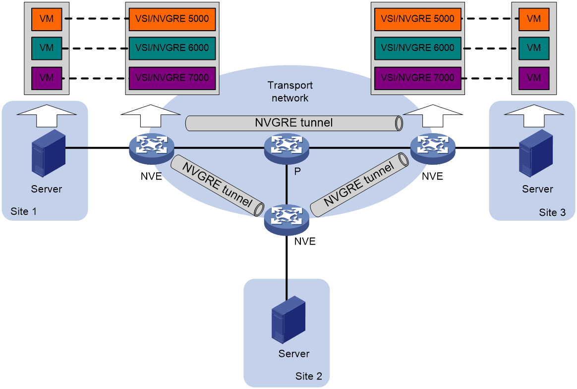
NVGRE network model
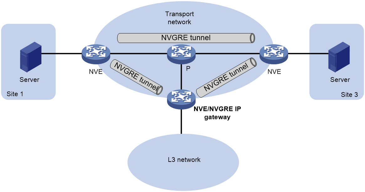
As shown in Figure 1, the transport edge devices assign VMs to different NVGRE networks, and then forward traffic between sites for VMs by using NVGRE tunnels.
The transport edge devices are network virtualization edges (NVEs). They can be servers that host VMs or independent network devices.
An H3C NVE uses VSIs and NVGRE tunnels to provide NVGRE services.
· VSI—A virtual switch instance is a virtual Layer 2 switched domain. Each VSI provides switching services only for one NVGRE network. VSIs learn MAC addresses and forward frames independently of one another. VMs in different sites have Layer 2 connectivity if they are in the same NVGRE network.
· NVGRE tunnel—Logical point-to-point tunnels between NVEs over the transport network. Each NVGRE tunnel can trunk multiple NVGRE networks.
NVEs encapsulate NVGRE traffic in the GRE and outer IP headers. The devices in the transport network forward NVGRE traffic only based on the outer IP header.
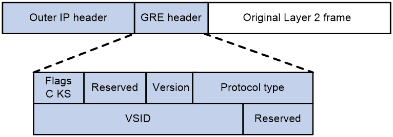
NVGRE packet format
As shown in Figure 2, an NVE encapsulates a frame in the following headers:
· 8-byte GRE header—NVGRE information for the frame.
¡ Flags—Contains 4 bits. The second bit is not defined.
- C bit—Checksum Present bit set to 0, indicating that the GRE header does not carry the GRE checksum.
- K bit—Key Present bit set to 1, indicating that the GRE header carries the VSID.
- S bit—Sequence Number Present bit set to 0, indicating that the GRE header does not carry a sequence number.
For more information about GRE, see Layer 3—IP Services Configuration Guide.
¡ Version—GRE version number.
¡ Protocol type—Passenger protocol type set to 0x6558, indicating that the payload is an Ethernet frame.
¡ 24-bit VSID—Virtual subnet identifier that identifies the NVGRE network of the frame.
· 20-byte outer IP header—Valid addresses of NVEs on the transport network. Devices in the transport network forward NVGRE packets based on the outer IP header.
Working mechanisms
The NVE uses the following process to forward an inter-site frame:
1. Assigns the frame to its matching NVGRE network.
2. Performs MAC learning on the NVGRE network's VSI.
3. Forwards the frame through NVGRE tunnels.
This section describes this process in detail. For intra-site frames in a VSI, the system performs MAC address table lookup in the VSI and forwards the frames out of site-facing interfaces. The system processes 802.1Q VLAN tags as described in "Access modes of VSIs."
Assignment of traffic to NVGRE networks
Traffic from the local site to a remote site
The NVE uses that is identical to an attachment circuit (AC) in L2VPN to match customer traffic on a site-facing interface. The NVE assigns customer traffic to an NVGRE network by mapping the AC to a VSI. .
Traffic from a remote site to the local site
When an NVGRE packet arrives at an NVGRE tunnel, the NVE uses the VSID in the packet to identify its NVGRE network.
MAC learning
The NVE performs source MAC learning on the VSI as a Layer 2 switch.
· For traffic from the local site to a remote site, the NVE learns the source MAC address before NVGRE encapsulation.
· For traffic from a remote site to the local site, the NVE learns the source MAC address after NVGRE de-encapsulation.
A VSI's MAC address table includes the following types of MAC address entries:
· Local MAC—Dynamic MAC entries learned from the local site. The outgoing interfaces are site-facing interfaces on which the MAC addresses are learned. NVGRE does not support manual local-MAC entries.
· Remote MAC—MAC entries learned from a remote site, including static and dynamic MAC entries. The outgoing interfaces for the MAC addresses are NVGRE tunnel interfaces.
¡ Static—Manually added MAC entries.
¡ Dynamic—MAC entries learned in the data plane from incoming traffic on NVGRE tunnels. The learned MAC addresses are contained in the inner Ethernet header.
For a remote address, the manual static entry has higher priority than the dynamic entry.
Traffic forwarding
The NVE uses the following processes to forward traffic at Layer 2:
· Unicast process—Applies to destination-known unicast traffic.
· Flood process—Applies to multicast, broadcast, and unknown unicast traffic.
When the NVE forwards NVGRE traffic, it processes the 802.1Q tag in the inner Ethernet header depending on the VSI access mode (VLAN or Ethernet mode). In VLAN access mode, sites can use different VLANs to provide the same service. For more information, see "Access modes of VSIs."
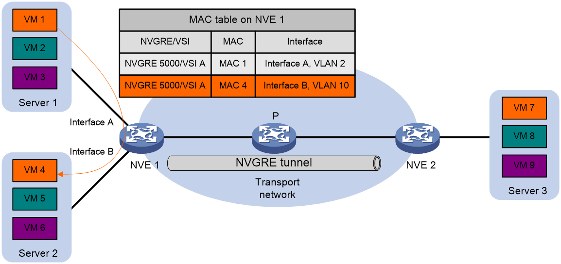
Intra-site unicast
As shown in Figure 3, for intra-site unicast traffic, the NVE looks up the VSI's MAC address table and forwards the traffic through the matching outgoing site-facing interface.
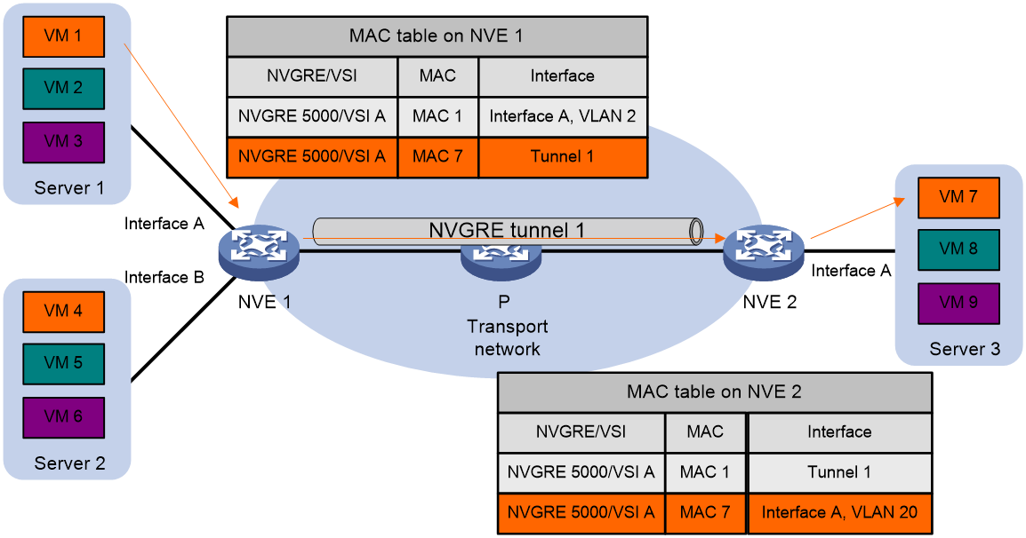
Inter-site unicast
The following process (see Figure 4) applies to a known unicast frame between sites:
1. The source NVE encapsulates the Ethernet frame in the GRE/IP header.
In the outer IP header, the source IP address is the source NVE's NVGRE tunnel source IP address. The destination IP address is the NVGRE tunnel destination IP address.
2. The source NVE forwards the encapsulated packet out of the outgoing NVGRE tunnel interface found in the VSI's MAC address table.
3. The intermediate transport devices (P devices) forward the frame to the destination NVE by using the outer IP header.
4. The destination NVE removes the headers on top of the inner Ethernet frame. It then performs MAC address table lookup in the NVGRE network's VSI to forward the frame out of the matching outgoing interface.
Flood
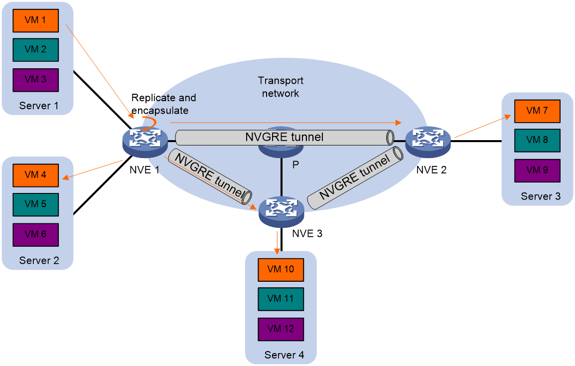
As shown in Figure 5, the NVE floods a broadcast, multicast, or unknown unicast frame to all site-facing interfaces and NVGRE tunnels in the NVGRE network, except for the incoming interface.
Each destination NVE floods the inner Ethernet frame to all the site-facing interfaces in the NVGRE network. To avoid loops, the destination NVEs do not flood the frame to NVGRE tunnels.
Access modes of VSIs
The access mode of a VSI determines how the NVE processes the 802.1Q VLAN tags in the Ethernet frames.
· VLAN access mode—Ethernet frames received from or sent to the local site must contain 802.1Q VLAN tags.
¡ For an Ethernet frame received from the local site, the NVE removes all its 802.1Q VLAN tags before forwarding the frame.
¡ For an Ethernet frame destined for the local site, the NVE adds 802.1Q VLAN tags to the frame before forwarding the frame.
In VLAN access mode, NVGRE packets sent between sites do not contain 802.1Q VLAN tags. You can use different 802.1Q VLANs to provide the same service in different sites.
· Ethernet access mode—The NVE does not process the 802.1Q VLAN tags of Ethernet frames received from or sent to the local site.
¡ For an Ethernet frame received from the local site, the NVE forwards the frame with the 802.1Q VLAN tags intact.
¡ For an Ethernet frame destined for the local site, the NVE forwards the frame without adding 802.1Q VLAN tags.
In Ethernet access mode, NVGRE packets sent between NVGRE sites contain 802.1Q VLAN tags. You must use the same VLAN to provide the same service between sites.
ARP flood suppression
ARP flood suppression reduces ARP request broadcasts by enabling the NVE to reply to ARP requests on behalf of VMs.
As shown in Figure 6, this feature snoops ARP packets to populate the ARP flood suppression table with local and remote MAC addresses. If an ARP request has a matching entry, the NVE replies to the request on behalf of the VM. If no match is found, the NVE floods the request to both local and remote sites.
Figure 6 ARP flood suppression
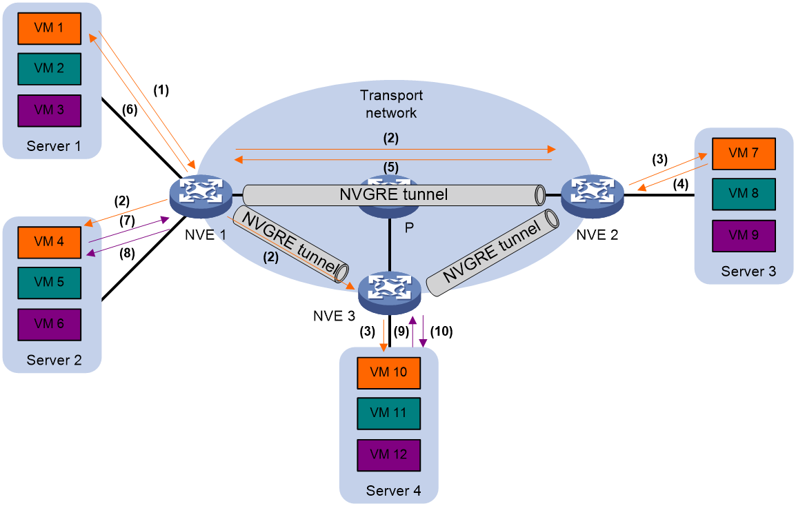
ARP flood suppression uses the following workflow:
1. VM 1 sends an ARP request to obtain the MAC address of VM 7.
2. NVE 1 creates a suppression entry for VM 1, and floods the ARP request in the NVGRE network.
3. NVE 2 and NVE 3 de-encapsulate the ARP request. The NVEs create a suppression entry for VM 1, and broadcast the request in the local site.
4. VM 7 sends an ARP reply.
5. NVE 2 creates a suppression entry for VM 7 and forwards the ARP reply to NVE 1.
6. NVE 1 de-encapsulates the ARP reply, creates a suppression entry for VM 7, and forwards the ARP reply to VM 1.
7. VM 4 sends an ARP request to obtain the MAC address of VM 1 or VM 7.
8. NVE 1 creates a suppression entry for VM 4 and replies to the ARP request.
9. VM 10 sends an ARP request to obtain the MAC address of VM 1.
10. NVE 3 creates a suppression entry for VM 10 and replies to the ARP request.
NVGRE IP gateways
An NVGRE IP gateway provides Layer 3 forwarding services for VMs in NVGRE networks. An NVGRE IP gateway can be an independent device or be collocated with an NVE. For more information about NVGRE IP gateway placement, see "Configuring NVGRE IP gateways."
Protocols and standards
draft-sridharan-virtualization-nvgre-04
Configuring basic NVGRE features
NVGRE tasks at a glance
To configure NVGRE, perform the following tasks:
2. Configuring an NVGRE tunnel
3. Creating an NVGRE network on a VSI
4. Assigning an NVGRE tunnel to an NVGRE network
6. (Optional.) Configuring static remote-MAC address entries
7. (Optional.) Confining unknown-unicast floods to the local site
8. (Optional.) Enabling ARP flood suppression
9. (Optional.) Enabling packet statistics for a VSI
Prerequisites for NVGRE
Configure a routing protocol on transport network devices for NVEs to reach one another.
Enabling L2VPN
1. Enter system view.
system-view
2. Enable L2VPN.
l2vpn enable
By default, L2VPN is disabled.
Configuring an NVGRE tunnel
About this task
NVGRE tunnels are manually created. When you create an NVGRE tunnel, you must specify its source IP address and destination IP address.
· Tunnel source IP address—The source IP address in the outer IP header of tunneled NVGRE packets. You can specify the IP address of an interface or specify an interface as the tunnel source interface. If an interface is specified, its primary IP address is used.
· Tunnel destination IP address—The destination IP address in the outer IP header of tunneled NVGRE packets. You must specify the IP address of an interface on a remote NVE.
Restrictions and guidelines
As a best practice, do not configure multiple NVGRE tunnels to use the same source and destination IP addresses.
This task provides basic NVGRE tunnel configuration. For more information about tunnel configuration and commands, see Layer 3—IP Services Configuration Guide and Layer 3—IP Services Command Reference.
Procedure
1. Enter system view.
system-view
2. Create an NVGRE tunnel interface and enter tunnel interface view.
interface tunnel tunnel-number mode nvgre
The endpoints of a tunnel must use the same tunnel mode.
3. Specify a source IP address or source interface for the tunnel.
source { ipv4-address | interface-type interface-number }
By default, no source IP address or source interface is specified for a tunnel.
4. Specify a destination IP address for the tunnel.
destination ipv4-address
By default, no destination IP address is specified for a tunnel.
Creating an NVGRE network on a VSI
1. Enter system view.
system-view
2. Create a VSI and enter VSI view.
vsi vsi-name
3. (Optional.) Configure a description for the VSI.
description text
By default, a VSI does not have a description.
4. Enable the VSI.
undo shutdown
By default, VSIs are up.
5. Create an NVGRE network and enter NVGRE network view.
nvgre nvgre-vsid
An NVGRE network is uniquely identified by its VSID. You can create only one NVGRE network on a VSI. The NVGRE networks must be unique among VSIs.
Assigning an NVGRE tunnel to an NVGRE network
About this task
To provide Layer 2 connectivity for an NVGRE network between two sites, you must assign the NVGRE tunnel between the sites to the NVGRE network. You can assign multiple NVGRE tunnels to an NVGRE network, and configure an NVGRE tunnel to trunk multiple NVGRE networks. NVEs use the VSID to identify traffic of different NVGRE networks.
When receiving flood traffic of an NVGRE network from the local site, an NVE floods the traffic to remote NVEs through all NVGRE tunnels of the NVGRE network.
Procedure
1. Enter system view.
system-view
2. Enter VSI view.
vsi vsi-name
3. Enter NVGRE network view.
nvgre nvgre-vsid
4. Assign an NVGRE tunnel to the NVGRE network.
tunnel tunnel-number
By default, an NVGRE network does not contain any NVGRE tunnels.
For full Layer 2 connectivity in the NVGRE network, make sure the NVGRE network contains the NVGRE tunnel between each pair of sites in the NVGRE network.
Mapping ACs to a VSI
Mapping a Layer 3 interface to a VSI
About this task
To assign the customer traffic on a Layer 3 interface to an NVGRE network, map the interface to the NVGRE network's VSI. The VSI uses its MAC address table to forward the customer traffic.
Restrictions and guidelines
Link aggregation group membership is mutually exclusive with VSI mappings on a Layer 3 interface. Do not map a VSI to a Layer 3 interface that is in a Layer 3 aggregation group.
Procedure
1. Enter system view.
system-view
2. Enter Layer 3 interface view.
interface interface-type interface-number
3. Configure the VLAN tag processing rule for incoming traffic.
l2vpn rewrite inbound tag { nest { c-vid vlan-id | s-vid vlan-id [ c-vid vlan-id ] } | remark 1-to-2 s-vid vlan-id c-vid vlan-id } [ symmetric ]
By default, VLAN tags of incoming traffic are not processed.
4. Map the Layer 3 interface to a VSI.
xconnect vsi vsi-name [ access-mode { ethernet | vlan } ] [ track track-entry-number&<1-3> ]
By default, a Layer 3 interface is not mapped to any VSI.
If the AC is a Layer 3 subinterface, you can specify the access mode. The default access mode is VLAN. If the AC is a Layer 3 interface, you cannot specify the access mode.
Configuring static remote-MAC address entries
1. Enter system view.
system-view
2. Add a static remote entry.
mac-address static mac-address interface tunnel tunnel-number vsi vsi-name
For the setting to take effect, make sure the VSI's NVGRE network has been created and specified on the NVGRE tunnel.
Confining unknown-unicast floods to the local site
About this task
By default, the NVE floods unknown unicast frames received from the local site to the following interfaces in the frame's NVGRE network:
· All site-facing interfaces except for the incoming interface.
· All NVGRE tunnel interfaces.
To confine unknown unicast traffic to the site-facing interfaces, use this feature to disable flooding for the VSI bound to the NVGRE network. The VSI will not flood unknown unicast frames to NVGRE tunnel interfaces.
To exclude a remote MAC address from the flood suppression done by using this feature, you can enable selective flood for the MAC address. The NVE will flood the frames destined for the MAC address to remote sites when unknown-unicast floods are confined to the local site.
Procedure
1. Enter system view.
system-view
2. Enter VSI view.
vsi vsi-name
3. Disable the VSI to flood unknown unicast traffic to NVGRE tunnel interfaces.
flooding disable
By default, unknown unicast traffic is flooded to all interfaces in the NVGRE network, except for the incoming interface.
4. (Optional.) Enable selective flood for a MAC address.
selective-flooding mac-address mac-address
Enabling ARP flood suppression
Restrictions and guidelines
The aging timer is fixed at 25 minutes for ARP flood suppression entries. If the suppression table is full, the NVE stops learning new entries. For the NVE to learn new entries, you must wait for old entries to age out, or use the reset arp suppression vsi command to clear the table.
If the flooding disable command is configured, set the MAC aging timer to a higher value than the aging timer for ARP flood suppression entries on all NVEs. This setting prevents the traffic blackhole that occurs when a MAC address entry ages out before its ARP flood suppression entry ages out.
To set the MAC aging timer, use the mac-address timer command.
Procedure
1. Enter system view.
system-view
2. Enter VSI view.
vsi vsi-name
3. Enable ARP flood suppression.
arp suppression enable
By default, ARP flood suppression is disabled.
Enabling packet statistics for a VSI
1. Enter system view.
system-view
2. Enter VSI view.
vsi vsi-name
3. Enable packet statistics for the VSI.
statistics enable
By default, packet statistics is disabled for all VSIs.
Display and maintenance commands for NVGRE
Execute display commands in any view and reset commands in user view.
|
Task |
Command |
|
Display ARP flood suppression entries on VSIs. |
In standalone mode: display arp suppression vsi [ name vsi-name ] [ count ] In IRF mode: display arp suppression vsi [ name vsi-name ] [ slot slot-number ] [ count ] |
|
Display information about tunnel interfaces. |
display interface [ tunnel [ number ] ] [ brief [ description | down ] ] |
|
Display L2VPN information for Layer 3 interfaces that are mapped to VSIs. |
display l2vpn interface [ vsi vsi-name | interface-type interface-number ] [ verbose ] |
|
Display MAC address entries for VSIs. |
display l2vpn mac-address [ vsi vsi-name ] [ dynamic ] [ count ] |
|
Display information about VSIs. |
display l2vpn vsi [ name vsi-name ] [ verbose ] |
|
Display NVGRE tunnel information for NVGRE networks. |
display nvgre tunnel [ vsid vsid ] |
|
Clear ARP flood suppression entries on VSIs. |
reset arp suppression vsi [ name vsi-name ] |
|
Clear dynamic MAC address entries on VSIs. |
reset l2vpn mac-address [ vsi vsi-name ] |
|
Clear packet statistics on VSIs. |
reset l2vpn statistics vsi [ name vsi-name ] |
|
|
NOTE: For more information about the display interface tunnel command, see tunneling commands in Layer 3—IP Services Command Reference. |
NVGRE network configuration examples
Example: Configuring a basic NVGRE network
Network configuration
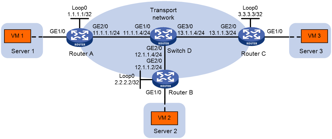
As shown in Figure 7:
· Configure NVGRE network 5000 on Router A, Router B, and Router C to provide Layer 2 connectivity for the VMs across the network sites.
· Manually establish NVGRE tunnels and assign the tunnels to NVGRE network 5000.
Procedure
1. Configure IP addresses and unicast routing settings:
# Assign IP addresses to the interfaces, as shown in Figure 7. (Details not shown.)
# Configure OSPF on all transport network devices (Routers A through D). (Details not shown.)
2. Configure Router A:
# Enable L2VPN.
<RouterA> system-view
[RouterA] l2vpn enable
# Create VSI vpna and NVGRE network 5000.
[RouterA] vsi vpna
[RouterA-vsi-vpna] nvgre 5000
[RouterA-vsi-vpna-nvgre-5000] quit
[RouterA-vsi-vpna] quit
# Assign an IP address to Loopback 0. The IP address will be used as the source IP address of the NVGRE tunnels to Router B and Router C.
[RouterA] interface loopback 0
[RouterA-Loopback0] ip address 1.1.1.1 255.255.255.255
[RouterA-Loopback0] quit
# Create an NVGRE tunnel to Router B. The tunnel interface name is Tunnel 1.
[RouterA] interface Tunnel 1 mode nvgre
[RouterA-Tunnel1] source 1.1.1.1
[RouterA-Tunnel1] destination 2.2.2.2
[RouterA-Tunnel1] quit
# Create an NVGRE tunnel to Router C. The tunnel interface name is Tunnel 2.
[RouterA] interface Tunnel 2 mode nvgre
[RouterA-Tunnel2] source 1.1.1.1
[RouterA-Tunnel2] destination 3.3.3.3
[RouterA-Tunnel2] quit
# Assign Tunnel 1 and Tunnel 2 to NVGRE network 5000.
[RouterA] vsi vpna
[RouterA-vsi-vpna] nvgre 5000
[RouterA-vsi-vpna-nvgre-5000] tunnel 1
[RouterA-vsi-vpna-nvgre-5000] tunnel 2
[RouterA-vsi-vpna-nvgre-5000] quit
[RouterA-vsi-vpna] quit
# Map GigabitEthernet 1/0 to VSI vpna.
[RouterA] interface gigabitethernet 1/0
[RouterA-GigabitEthernet1/0] xconnect vsi vpna
[RouterA-GigabitEthernet1/0] quit
3. Configure Router B:
# Enable L2VPN.
<RouterB> system-view
[RouterB] l2vpn enable
# Create VSI vpna and NVGRE network 5000.
[RouterB] vsi vpna
[RouterB-vsi-vpna] nvgre 5000
[RouterB-vsi-vpna-nvgre-5000] quit
[RouterB-vsi-vpna] quit
# Assign an IP address to Loopback 0. The IP address will be used as the source IP address of the NVGRE tunnels to Router A and Router C.
[RouterB] interface loopback 0
[RouterB-Loopback0] ip address 2.2.2.2 255.255.255.255
[RouterB-Loopback0] quit
# Create an NVGRE tunnel to Router A. The tunnel interface name is Tunnel 2.
[RouterB] interface Tunnel 2 mode nvgre
[RouterB-Tunnel2] source 2.2.2.2
[RouterB-Tunnel2] destination 1.1.1.1
[RouterB-Tunnel2] quit
# Create an NVGRE tunnel to Router C. The tunnel interface name is Tunnel 3.
[RouterB] interface Tunnel 3 mode nvgre
[RouterB-Tunnel3] source 2.2.2.2
[RouterB-Tunnel3] destination 3.3.3.3
[RouterB-Tunnel3] quit
# Assign Tunnel 2 and Tunnel 3 to NVGRE network 5000.
[RouterB] vsi vpna
[RouterB-vsi-vpna] nvgre 5000
[RouterB-vsi-vpna-nvgre-5000] tunnel 2
[RouterB-vsi-vpna-nvgre-5000] tunnel 3
[RouterB-vsi-vpna-nvgre-5000] quit
[RouterB-vsi-vpna] quit
# Map GigabitEthernet 1/0 to VSI vpna.
[RouterB] interface gigabitethernet 1/0
[RouterB-GigabitEthernet1/0] xconnect vsi vpna
[RouterB-GigabitEthernet1/0] quit
4. Configure Router C:
# Enable L2VPN.
<RouterC> system-view
[RouterC] l2vpn enable
# Create VSI vpna and NVGRE network 5000.
[RouterC] vsi vpna
[RouterC-vsi-vpna] nvgre 5000
[RouterC-vsi-vpna-nvgre-5000] quit
[RouterC-vsi-vpna] quit
# Assign an IP address to Loopback 0. The IP address will be used as the source IP address of the NVGRE tunnels to Router A and Router B.
[RouterC] interface loopback 0
[RouterC-Loopback0] ip address 3.3.3.3 255.255.255.255
[RouterC-Loopback0] quit
# Create an NVGRE tunnel to Router A. The tunnel interface name is Tunnel 1.
[RouterC] interface Tunnel 1 mode nvgre
[RouterC-Tunnel1] source 3.3.3.3
[RouterC-Tunnel1] destination 1.1.1.1
[RouterC-Tunnel1] quit
# Create an NVGRE tunnel to Router B. The tunnel interface name is Tunnel 3.
[RouterC] interface Tunnel 3 mode nvgre
[RouterC-Tunnel3] source 3.3.3.3
[RouterC-Tunnel3] destination 2.2.2.2
[RouterC-Tunnel3] quit
# Assign Tunnel 1 and Tunnel 3 to NVGRE 5000.
[RouterC] vsi vpna
[RouterC-vsi-vpna] nvgre 5000
[RouterC-vsi-vpna-nvgre-5000] tunnel 1
[RouterC-vsi-vpna-nvgre-5000] tunnel 3
[RouterC-vsi-vpna-nvgre-5000] quit
[RouterC-vsi-vpna] quit
# Map GigabitEthernet 1/0 to VSI vpna.
[RouterC] interface gigabitethernet 1/0
[RouterC-GigabitEthernet1/0] xconnect vsi vpna
[RouterC-GigabitEthernet1/0] quit
Verifying the configuration
1. Verify the NVGRE settings on the NVEs. This example uses Router A.
# Verify that the NVGRE tunnel interfaces on the NVE are up.
[RouterA] display interface tunnel 1
Tunnel1
Current state: UP
Line protocol state: UP
Description: Tunnel1 Interface
Bandwidth: 64 kbps
Maximum transmission unit: 64000
Internet protocol processing: disabled
Output queue - Urgent queuing: Size/Length/Discards 0/100/0
Output queue - Protocol queuing: Size/Length/Discards 0/500/0
Output queue - FIFO queuing: Size/Length/Discards 0/75/0
Last clearing of counters: Never
Tunnel source 1.1.1.1, destination 3.3.3.3
Tunnel protocol/transport GRE_NVGRE/IP
Last 300 seconds input rate: 0 bytes/sec, 0 bits/sec, 0 packets/sec
Last 300 seconds output rate: 0 bytes/sec, 0 bits/sec, 0 packets/sec
Input: 0 packets, 0 bytes, 0 drops
Output: 0 packets, 0 bytes, 0 drops
# Verify that the NVGRE tunnels have been assigned to the NVGRE network.
[RouterA] display l2vpn vsi verbose
VSI Name: vpna
VSI Index : 0
VSI State : Up
MTU : 1500
Bandwidth : -
Broadcast Restrain : -
Multicast Restrain : -
Unknown Unicast Restrain: -
MAC Learning : Enabled
MAC Table Limit : -
Drop Unknown : -
Flooding : Enabled
NVGRE VSID : 5000
Tunnels:
Tunnel Name Link ID State Type
Tunnel1 0x7000001 UP Manual
Tunnel2 0x7000002 UP Manual
ACs:
AC Link ID State
GE1/0 0 Up
# Verify that the NVE has learned the MAC addresses of remote VMs.
[RouterA] display l2vpn mac-address
MAC Address Type VSI Name Link ID Aging Time
cc3e-5f9c-6cdb Dynamic vpna Tunnel1 Aging
cc3e-5f9c-23dc Dynamic vpna Tunnel2 Aging
--- 2 mac address(es) found ---
2. Verify that VM 1, VM 2, and VM 3 can ping each other. (Details not shown.)
Configuring NVGRE IP gateways
About NVGRE IP gateways
The following are available IP gateway placement designs for NVGRE networks:
· NVGRE IP gateways separated from NVEs—Use an NVGRE-unaware device as a gateway to the external network for NVGRE networks. On the gateway, you do not need to configure NVGRE settings.
· NVGRE IP gateways collocated with NVEs—Use one NVE to provide Layer 3 forwarding for NVGRE networks. Typically, the gateway-collocated NVE connects to other NVEs and the external network. To use this design, make sure the IP gateway has sufficient bandwidth and processing capability. In a collocation design, the NVEs use virtual Layer 3 VSI interfaces as gateway interfaces to provide services for NVGRE networks.
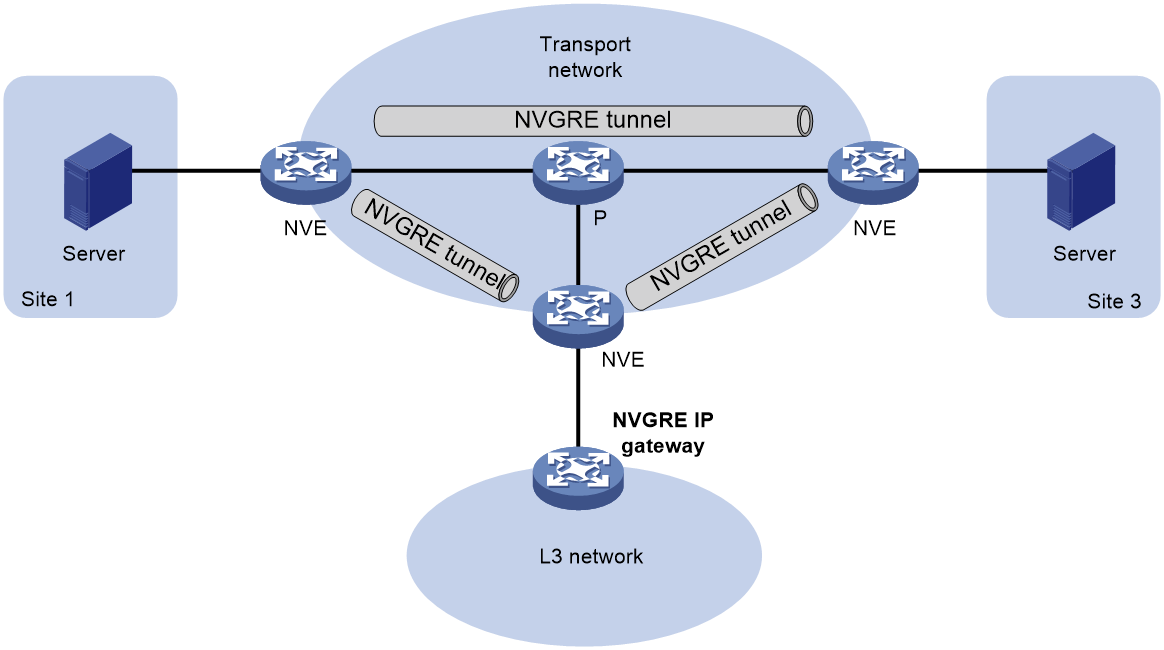
NVGRE IP gateway separated from NVEs
As shown in Figure 8, an independent NVGRE IP gateway connects a Layer 3 network to an NVE. VMs send Layer 3 traffic in Layer 2 frames to the gateway through NVGRE tunnels. When the tunneled NVGRE packets arrive, the NVE terminates the NVGRE networks and forwards the inner frames to the gateway. In this gateway placement design, the NVE does not perform Layer 3 forwarding for NVGRE networks.
Figure 8 NVGRE IP gateway separated from NVEs
NVGRE IP gateway on an NVE
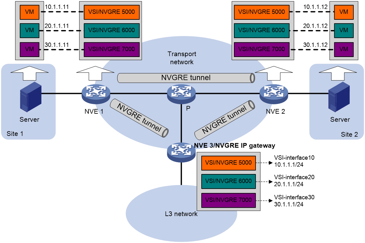
As shown in Figure 9, an NVE acts as a gateway for VMs in the NVGRE networks. The NVE both terminates the NVGRE networks and performs Layer 3 forwarding for the VMs.
Figure 9 NVGRE IP gateway on an NVE
As shown in Figure 10, the network uses the following process to forward Layer 3 traffic from VM 10.1.1.11 to the Layer 3 network:
1. The VM sends an ARP request to obtain the MAC address of the gateway (NVE 3) at 10.1.1.1.
2. NVE 1 floods the ARP request to all remote NVEs.
3. NVE 3 de-encapsulates the ARP request, creates an ARP entry for the VM, and sends an ARP reply to the VM.
4. NVE 1 forwards the ARP reply to the VM.
5. The VM learns the MAC address of the gateway, and sends the Layer 3 traffic to the gateway.
6. NVE 3 removes the NVGRE encapsulation and inner Ethernet header for the traffic, and forwards the traffic to the destination node.
Inter-NVGRE network forwarding is the same as this process except for the last step. At the last step of inter-NVGRE network forwarding, the gateway replaces the source-NVGRE encapsulation with the destination-NVGRE encapsulation, and then forwards the traffic.
Figure 10 ARP learning on the NVE that acts as an NVGRE IP gateway
Prerequisites for NVGRE IP gateway configuration
Before you configure an NVGRE IP gateway, you must perform the required tasks in "Configuring basic NVGRE features."
Configuring an NVGRE IP gateway on an NVE
1. Enter system view.
system-view
2. Create a VSI interface and enter VSI interface view.
interface vsi-interface vsi-interface-id
3. Assign an IP address to the VSI interface.
ip address ip-address { mask | mask-length }
By default, no IP address is assigned to a VSI interface.
4. Enable the VSI interface.
undo shutdown
By default, a VSI interface is up.
5. Return to system view.
quit
6. Enter VSI view.
vsi vsi-name
7. Specify a gateway interface for the VSI.
gateway vsi-interface vsi-interface-id
By default, no gateway interface is specified for a VSI.
Configuring optional parameters for a VSI interface
1. Enter system view.
system-view
2. Enter VSI interface view.
interface vsi-interface vsi-interface-id
3. Assign a MAC address to the VSI interface.
mac-address mac-address
By default, VSI interfaces use the MAC address of the virtual NIC.
4. Configure the description of the VSI interface.
description text
The default description of a VSI interface is interface-name plus Interface (for example, Vsi-interface100 Interface).
5. Set the MTU for the VSI interface.
mtu mtu-value
The default MTU of VSI interfaces is 1500 bytes.
6. Set the expected bandwidth for the VSI interface.
bandwidth bandwidth-value
The default expected bandwidth (in kbps) equals the interface baudrate divided by 1000.
The expected bandwidth is an informational parameter used only by higher-layer protocols for calculation. You cannot adjust the actual bandwidth of an interface by using this command.
Restoring the default settings of the VSI interface
Restrictions and guidelines
|
|
CAUTION: This operation might interrupt ongoing network services. Make sure you are fully aware of the impact of this operation when you perform it on a live network. |
This operation might fail to restore the default settings for some commands for reasons such as command dependencies or system restrictions. Use the display this command in interface view to identify these commands. Use their undo forms or follow the command reference to restore their default settings. If your restoration attempt still fails, follow the error message instructions to resolve the problem.
Procedure
1. Enter system view.
system-view
2. Enter VSI interface view.
interface vsi-interface vsi-interface-id
3. Restore the default settings of the VSI interface.
default
Display and maintenance commands for NVGRE IP gateway
Execute display commands in any view and reset commands in user view.
|
Task |
Command |
|
Display information about VSI interfaces. |
display interface [ vsi-interface [ vsi-interface-id ] ] [ brief [ description | down ] ] |
|
Clear statistics on VSI interfaces. |
reset counters interface [ vsi-interface [ vsi-interface-id ] ] |
NVGRE IP gateway configuration examples
Example: Configuring a basic NVGRE IP gateway
Network configuration
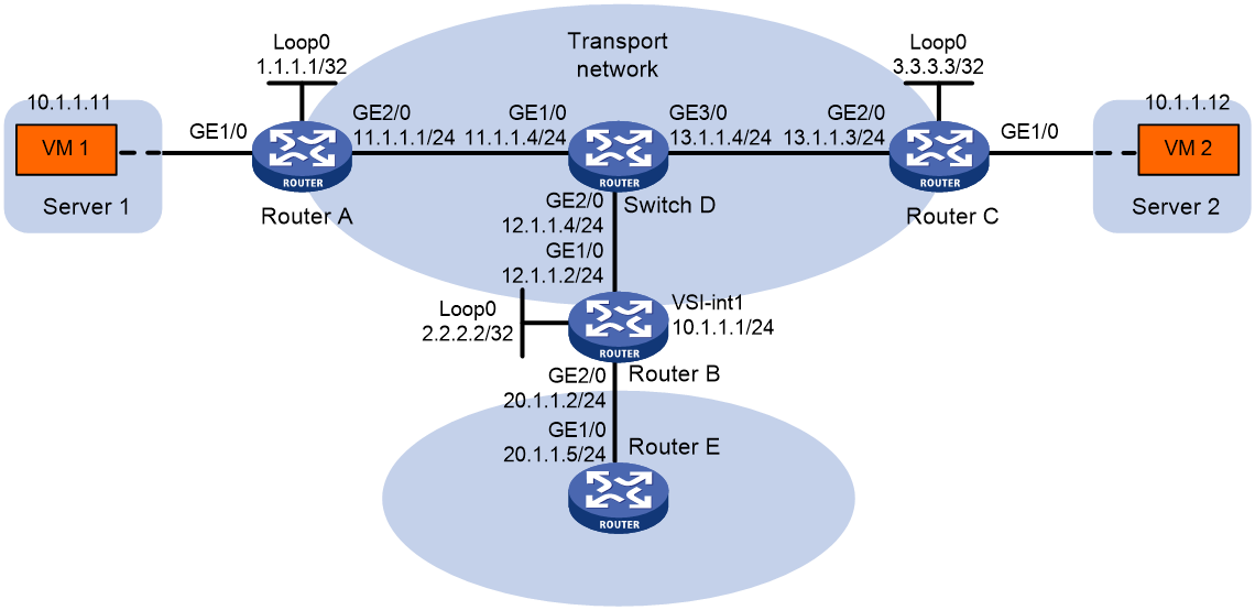
As shown in Figure 11:
· Configure NVGRE network 5000 on Router A, Router B, and Router C to provide connectivity for the VMs across the network sites.
· Configure an NVGRE IP gateway on Router B to provide gateway services for NVGRE network 5000.
· Manually establish NVGRE tunnels and assign the tunnels to NVGRE network 5000.
Procedure
1. Configure IP addresses and unicast routing settings:
# Assign IP addresses to the interfaces, as shown in Figure 11. (Details not shown.)
# Configure OSPF on all transport network routers (Routers A through D). (Details not shown.)
# Configure OSPF to advertise routes to networks 10.1.1.0/24 and 20.1.1.0/24 on Router B and Router E. (Details not shown.)
2. Configure Router A:
# Enable L2VPN.
<RouterA> system-view
[RouterA] l2vpn enable
# Create VSI vpna and NVGRE network 5000.
[RouterA] vsi vpna
[RouterA-vsi-vpna] nvgre 5000
[RouterA-vsi-vpna-nvgre-5000] quit
[RouterA-vsi-vpna] quit
# Assign an IP address to Loopback 0. The IP address will be used as the source IP address of the NVGRE tunnels to Router B and Router C.
[RouterA] interface loopback 0
[RouterA-Loopback0] ip address 1.1.1.1 255.255.255.255
[RouterA-Loopback0] quit
# Create an NVGRE tunnel to Router B. The tunnel interface name is Tunnel 1.
[RouterA] interface Tunnel 1 mode nvgre
[RouterA-Tunnel1] source 1.1.1.1
[RouterA-Tunnel1] destination 2.2.2.2
[RouterA-Tunnel1] quit
# Create an NVGRE tunnel to Router C. The tunnel interface name is Tunnel 2.
[RouterA] interface Tunnel 2 mode nvgre
[RouterA-Tunnel2] source 1.1.1.1
[RouterA-Tunnel2] destination 3.3.3.3
[RouterA-Tunnel2] quit
# Assign Tunnel 1 and Tunnel 2 to NVGRE network 5000.
[RouterA] vsi vpna
[RouterA-vsi-vpna] nvgre 5000
[RouterA-vsi-vpna-nvgre-5000] tunnel 1
[RouterA-vsi-vpna-nvgre-5000] tunnel 2
[RouterA-vsi-vpna-nvgre-5000] quit
[RouterA-vsi-vpna] quit
# Map GigabitEthernet 1/0 to VSI vpna.
[RouterA] interface gigabitethernet 1/0
[RouterA-GigabitEthernet1/0] xconnect vsi vpna
[RouterA-GigabitEthernet1/0] quit
3. Configure Router B:
# Enable L2VPN.
<RouterB> system-view
[RouterB] l2vpn enable
# Create VSI vpna and NVGRE network 5000.
[RouterB] vsi vpna
[RouterB-vsi-vpna] nvgre 5000
[RouterB-vsi-vpna-nvgre-5000] quit
[RouterB-vsi-vpna] quit
# Assign an IP address to Loopback 0. The IP address will be used as the source IP address of the NVGRE tunnels to Router A and Router C.
[RouterB] interface loopback 0
[RouterB-Loopback0] ip address 2.2.2.2 255.255.255.255
[RouterB-Loopback0] quit
# Create an NVGRE tunnel to Router A. The tunnel interface name is Tunnel 2.
[RouterB] interface Tunnel 2 mode nvgre
[RouterB-Tunnel2] source 2.2.2.2
[RouterB-Tunnel2] destination 1.1.1.1
[RouterB-Tunnel2] quit
# Create an NVGRE tunnel to Router C. The tunnel interface name is Tunnel 3.
[RouterB] interface Tunnel 3 mode nvgre
[RouterB-Tunnel3] source 2.2.2.2
[RouterB-Tunnel3] destination 3.3.3.3
[RouterB-Tunnel3] quit
# Assign Tunnel 2 and Tunnel 3 to NVGRE network 5000.
[RouterB] vsi vpna
[RouterB-vsi-vpna] nvgre 5000
[RouterB-vsi-vpna-nvgre-5000] tunnel 2
[RouterB-vsi-vpna-nvgre-5000] tunnel 3
[RouterB-vsi-vpna-nvgre-5000] quit
[RouterB-vsi-vpna] quit
# Create VSI-interface 1 and assign the interface an IP address. The IP address will be used as the gateway address for NVGRE network 5000.
[RouterB] interface vsi-interface 1
[RouterB-Vsi-interface1] ip address 10.1.1.1 255.255.255.0
[RouterB-Vsi-interface1] quit
# Specify VSI-interface 1 as the gateway interface for VSI vpna.
[RouterB] vsi vpna
[RouterB-vsi-vpna] gateway vsi-interface 1
[RouterB-vsi-vpna] quit
4. Configure Router C:
# Enable L2VPN.
<RouterC> system-view
[RouterC] l2vpn enable
# Create VSI vpna and NVGRE network 5000.
[RouterC] vsi vpna
[RouterC-vsi-vpna] nvgre 5000
[RouterC-vsi-vpna-nvgre-5000] quit
[RouterC-vsi-vpna] quit
# Assign an IP address to Loopback 0. The IP address will be used as the source IP address of the NVGRE tunnels to Router A and Router B.
[RouterC] interface loopback 0
[RouterC-Loopback0] ip address 3.3.3.3 255.255.255.255
[RouterC-Loopback0] quit
# Create an NVGRE tunnel to Router A. The tunnel interface name is Tunnel 1.
[RouterC] interface Tunnel 1 mode nvgre
[RouterC-Tunnel1] source 3.3.3.3
[RouterC-Tunnel1] destination 1.1.1.1
[RouterC-Tunnel1] quit
# Create an NVGRE tunnel to Router B. The tunnel interface name is Tunnel 3.
[RouterC] interface Tunnel 3 mode nvgre
[RouterC-Tunnel3] source 3.3.3.3
[RouterC-Tunnel3] destination 2.2.2.2
[RouterC-Tunnel3] quit
# Assign Tunnel 1 and Tunnel 3 to NVGRE network 5000.
[RouterC] vsi vpna
[RouterC-vsi-vpna] nvgre 5000
[RouterC-vsi-vpna-nvgre-5000] tunnel 1
[RouterC-vsi-vpna-nvgre-5000] tunnel 3
[RouterC-vsi-vpna-nvgre-5000] quit
[RouterC-vsi-vpna] quit
# Map GigabitEthernet 1/0 to VSI vpna.
[RouterC] interface gigabitethernet 1/0
[RouterC-GigabitEthernet1/0] xconnect vsi vpna
[RouterC-GigabitEthernet1/0] quit
Verifying the configuration
1. Verify the NVGRE IP gateway settings on Router B:
# Verify that the NVGRE tunnel interfaces are up on Router B.
[RouterB] display interface tunnel 2
Tunnel2
Current state: UP
Line protocol state: UP
Description: Tunnel2 Interface
Bandwidth: 64 kbps
Maximum transmission unit: 64000
Internet protocol processing: disabled
Output queue - Urgent queuing: Size/Length/Discards 0/100/0
Output queue - Protocol queuing: Size/Length/Discards 0/500/0
Output queue - FIFO queuing: Size/Length/Discards 0/75/0
Last clearing of counters: Never
Tunnel source 2.2.2.2, destination 1.1.1.1
Tunnel protocol/transport GRE_NVGRE/IP
Last 300 seconds input rate: 0 bytes/sec, 0 bits/sec, 0 packets/sec
Last 300 seconds output rate: 0 bytes/sec, 0 bits/sec, 0 packets/sec
Input: 0 packets, 0 bytes, 0 drops
Output: 0 packets, 0 bytes, 0 drops
# Verify that VSI-interface 1 is up.
[RouterB] display interface vsi-interface 1
Vsi-interface1
Current state: UP
Line protocol state: UP
Description: Vsi-interface1 Interface
Bandwidth: 1000000 kbps
Maximum transmission unit: 1500
Internet address: 10.1.1.1/24 (primary)
IP packet frame type: Ethernet II, hardware address: 0011-2200-0102
IPv6 packet frame type: Ethernet II, hardware address: 0011-2200-0102
Physical: Unknown, baudrate: 1000000 kbps
Last clearing of counters: Never
Last 300 seconds input rate: 0 bytes/sec, 0 bits/sec, 0 packets/sec
Last 300 seconds output rate: 0 bytes/sec, 0 bits/sec, 0 packets/sec
Input: 0 packets, 0 bytes, 0 drops
Output: 0 packets, 0 bytes, 0 drops
# Verify that the NVGRE tunnels have been assigned to the NVGRE network, and VSI-interface 1 is the gateway interface of VSI vpna.
[RouterB] display l2vpn vsi verbose
VSI Name: vpna
VSI Index : 0
VSI State : Up
MTU : 1500
Bandwidth : -
Broadcast Restrain : -
Multicast Restrain : -
Unknown Unicast Restrain: -
MAC Learning : Enabled
MAC Table Limit : -
Drop Unknown : -
Flooding : Enabled
Gateway interface : VSI-interface 1
NVGRE VSID : 5000
Tunnels:
Tunnel Name Link ID State Type
Tunnel2 0x7000002 Up Manual
Tunnel3 0x7000003 Up Manual
# Verify that Router B has created ARP entries for the VMs.
[RouterB] display arp
Type: S-Static D-Dynamic O-Openflow M-Multiport I-Invalid
IP address MAC address VLAN/VSI name Interface/Link ID Aging Type
12.1.1.4 000c-2999-e04f -- GE1/0 6 D
20.1.1.5 000c-29c1-5e46 -- GE2/0 19 D
10.1.1.11 0000-1234-0001 -- Vsi1 20 D
10.1.1.12 0000-1234-0002 -- Vsi1 19 D
# Verify that Router B has created FIB entries for the VMs.
[RouterB] display fib 10.1.1.11
Destination count: 1 FIB entry count: 1
Flag:
U:Useable G:Gateway H:Host B:Blackhole D:Dynamic S:Static
R:Relay F:FRR
Destination/Mask Nexthop Flag OutInterface/Token Label
10.1.1.11/32 10.1.1.11 UH Vsi1 Null
2. Verify that the VMs can access the WAN:
# Verify that VM 1 and VM 2 can ping each other. (Details not shown.)
# Verify that VM 1, VM 2, and GigabitEthernet 1/0/1 (20.1.1.5) on Router E can ping each other. (Details not shown.)