- Table of Contents
- Related Documents
-
| Title | Size | Download |
|---|---|---|
| 01-IRF (star-topology) configuration | 595.78 KB |
Contents
File system naming conventions
Multi-active handling procedure
Restrictions and guidelines: IRF configuration
Hardware compatibility with IRF
IRF topo-domain ID restrictions
Transceiver modules and cables selection for IRF
Feature compatibility and configuration restrictions with IRF
Licensing requirements for IRF
Assigning a member ID to each IRF member device
Specifying a priority for each member device
Assigning the same IRF topo-domain ID to the member devices
Assigning links to the IRF port
Saving configuration to the next-startup configuration file
Connecting IRF network interfaces
Setting the operating mode to IRF mode
Restrictions and guidelines for MAD configuration
Excluding a network interface from the shutdown action upon detection of multi-active collision
Optimizing IRF settings for an IRF fabric
Changing the member ID of a member device
Changing the IRF topo-domain ID for the IRF fabric
Configuring a member device description
Configuring IRF bridge MAC address settings
Enabling software auto-update for software image synchronization
Removing a member device from the IRF fabric
Adding a removed member device back to the IRF fabric
Display and maintenance commands for IRF
Example: Setting up an IRF fabric
Example: Migrating an IRF member device
Configuring an IRF fabric
About IRF
The Intelligent Resilient Framework (IRF) technology is a true stacking technology that creates a large virtual stack called IRF fabric from multiple devices to provide data center class availability and scalability. IRF offers processing power, interaction, unified management, and uninterrupted maintenance of multiple devices.
IRF network model
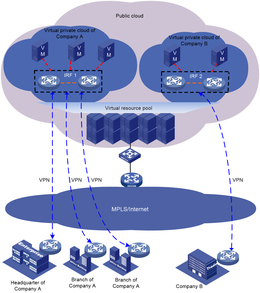
As shown in Figure 1, two IRF fabrics are deployed in a public cloud to provide virtual private cloud services for different tenants. The devices in each IRF fabric appear as a single node to the upper-layer and lower-layer devices.
Figure 1 IRF application scenario
IRF benefits
IRF provides the following benefits:
· Simplified topology and easy management—An IRF fabric appears as one node and is accessible at a single IP address on the network. You can use this IP address to log in at any member device to manage all the members of the IRF fabric. In addition, you do not need to run the spanning tree feature among the IRF members.
· 1:N redundancy—In an IRF fabric, one member acts as the master to manage and control the entire IRF fabric. All the other members process services while backing up the master. When the master fails, all the other member devices elect a new master from among them to take over without interrupting services.
· Star topology—The IRF member devices are connected in star topology through a Layer 2 network. Service traffic and IRF protocol packets are delivered between member devices over existing physical links. You do not need to use dedicated physical links to connect IRF member devices.
· IRF link redundancy—You can assign several links to an IRF port for redundancy. You do not need to aggregate the links. The IRF technology removes the loop automatically.
· Multichassis link aggregation—You can use the Ethernet link aggregation feature to aggregate the physical links between the IRF fabric and its upstream or downstream devices across the IRF members.
· Network scalability and resiliency—Processing capacity of an IRF fabric equals the total processing capacities of all the members. You can add and remove IRF member devices as needed without causing network topology change.
Basic concepts
Operating mode
The device operates in one of the following modes:
· Standalone mode—The device cannot join an IRF fabric.
· IRF mode—The device can join an IRF fabric.
IRF member roles
IRF uses two member roles: master and standby.
When devices form an IRF fabric, they elect a master to manage and control the IRF fabric, and all the other devices back up the master. When the master device fails, the other devices automatically elect a new master. For more information about master election, see "Master election."
IRF member ID
An IRF fabric uses member IDs to uniquely identify and manage its members.
Two devices cannot form an IRF fabric if they use the same member ID. A device cannot join an IRF fabric if its member ID has been used in the IRF fabric.
Member priority
Member priority determines the possibility of a member device to be elected the master. A member with higher priority is more likely to be elected the master.
IRF port
An IRF port is a logical interface that forwards data and IRF control packets between IRF member devices.
Every IRF-capable device has one IRF port. In standalone mode, the IRF port is named irf-port. In IRF mode, the IRF port is named irf-port n, where n is the IRF member ID of the device.
An IRF port must contain a minimum of one channel to send data and control packets.
An IRF port goes down when all its physical links are down.
IRF links
Links of the network interfaces bound to IRF ports are called IRF links.
You can configure an IRF link as one of the following channels:
· Control channel—The link forwards only IRF control packets between member devices.
· Data channel—The link forwards only data packets between member devices.
· Hybrid channel—The link forwards both control and data packets.
For more information about network interfaces that can be used for IRF links, see "IRF network interfaces."
IRF topo-domain ID
An IRF topo-domain ID uniquely identifies an IRF fabric. Devices must have the same IRF topo-domain ID to form one IRF fabric.
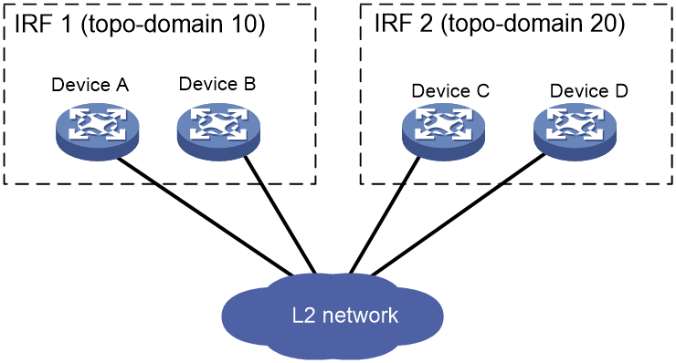
As shown in Figure 2, IRF fabric 1 contains Device A and Device B, and IRF fabric 2 contains Device C and Device D. The IRF fabrics can reach each other at Layer 2. When a member device receives a packet from an IRF link, it checks the topo-domain ID to determine whether the packet is from the local IRF fabric. Then, the member device can handle the packet correctly.
Figure 2 A network that contains two IRF topo-domains
MAD
An IRF link failure causes an IRF fabric to split in two IRF fabrics operating with the same Layer 3 settings, including the same IP address. To avoid IP address collision and network problems, IRF uses multi-active detection (MAD) mechanisms to detect the presence of multiple identical IRF fabrics, handle collisions, and recover from faults.
IRF MAD domain ID
An IRF MAD domain ID uniquely identifies an IRF MAD domain.
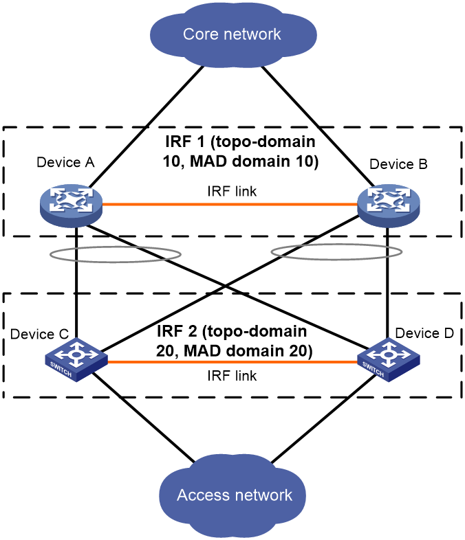
As shown in Figure 3, IRF fabric 1 contains Device A and Device B, and IRF fabric 2 contains Device C and Device D. Both fabrics use the LACP aggregate links between them for MAD. When a member device receives an extended LACPDU for MAD, it checks the MAD domain ID to determine whether the packet is from the local IRF fabric. Then, the member device can handle the packet correctly.
For easy management, you can assign the same value to the IRF topo-domain ID and MAD domain ID for an IRF fabric. For more information about IRF MAD domain ID configuration, see "Configuring MAD."
Figure 3 A network that contains two IRF MAD domains
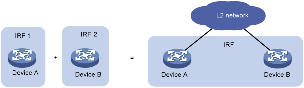
IRF merge
IRF merge occurs when two split IRF fabrics reunite or when two independent IRF fabrics are united, as shown in Figure 4.
IRF split
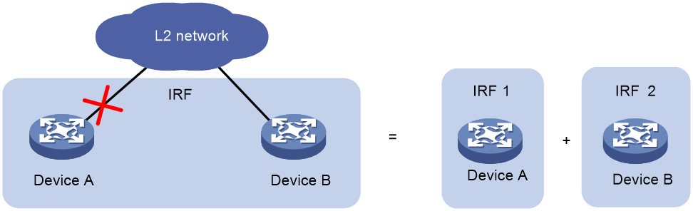
IRF split occurs when an IRF fabric breaks up into multiple IRF fabrics when Layer 2 connectivity is lost, as shown in Figure 5. The split IRF fabrics operate with the same IP address. IRF split causes routing and forwarding problems on the network.
Network topology
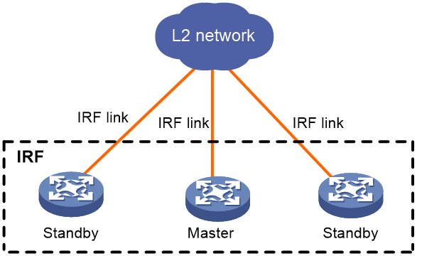
The IRF implementation of the device supports star topology. As shown in Figure 6, member devices are connected through a Layer 2 network. The member devices can communicate with one another as long as they have Layer 2 connectivity.
An IRF link can transmit IRF protocol packets, data packets, or both. For high availability, set up redundant IRF links between IRF member devices.
As a best practice to reduce data traffic across member devices, make sure the incoming and outgoing interfaces of packets for a session are on the same IRF member device.
Figure 6 Star-topology IRF fabric
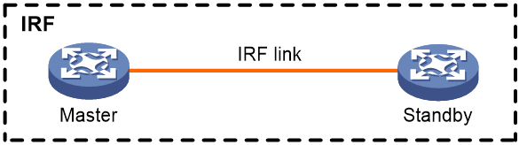
If the IRF fabric contains only two member devices, you can connect the member devices directly or through a Layer 2 network.
Figure 7 IRF fabric that contains directly connected member devices
Master election
Master election occurs each time the IRF topology changes in the following situations:
· The IRF fabric is established.
· The master device fails or is removed.
· The IRF fabric splits.
· IRF fabrics merge.
Master election selects a master in the following order:
1. Current master, even if a new member has higher priority.
When an IRF fabric is being formed, all members consider themselves as the master. This rule is skipped.
2. Member with higher priority.
3. Member with the longest system uptime.
Two members are considered to start up at the same time if the difference between their startup times is equal to or less than 10 minutes. For these members, the next tiebreaker applies.
4. Member with the lowest CPU MAC address.
For the establishment of a new IRF fabric, the standby devices must reboot to join the IRF fabric after the master election.
For an IRF merge, devices must reboot if they are in the IRF fabric that fails the master election.
Interface naming conventions
In standalone mode, an interface is numbered in the slot-number/interface-index format.
· slot-number—Slot number of the interface.
· interface-index—Interface index on the device. Interface index depends on the number of interfaces available on the device. To identify the index of an interface, examine its interface index mark on the chassis.
For example:
# Configure the description of the first interface GigabitEthernet 1/1 on the device as for LAN1.
<Sysname> system-view
[Sysname] interface gigabitethernet 1/1
[Sysname-GigabitEthernet1/1] description for LAN1
In IRF mode, the IRF member ID is added to an interface number as the first segment. An interface is named in the chassis-number/slot-number/interface-index format. The chassis-number argument represents the IRF member ID. The default IRF member ID is 1. Any change to the member ID takes effect after a reboot.
For example:
# Configure the description of the first interface GigabitEthernet 1/1/1 on member device 1 as for LAN1.
<Sysname> system-view
[Sysname] interface gigabitethernet 1/1/1
[Sysname-GigabitEthernet1/1/1] description for LAN1
File system naming conventions
In standalone mode, you can use the storage device name to access the device's file system.
On a multimember IRF fabric, you can use the storage device name to access the file system of the master. To access the file system of any other member device, use the name in the slotmember-ID#storage-device-name format.
For more information about storage device naming conventions, see Fundamentals Configuration Guide.
For example:
· To create and access the test folder under the root directory of the flash memory on the master device:
<Master> mkdir test
Creating directory flash:/test... Done.
<Master> cd test
<Master> dir
Directory of flash:/test
The directory is empty.
524288 KB total (29832 KB free)
· To create and access the test folder under the root directory of the flash memory on member device 2:
<Master> mkdir slot2#flash:/test
Creating directory slot2#flash:/test... Done.
<Master> cd slot2#flash:/test
<Master> dir
Directory of slot2#flash:/test
The directory is empty.
524288 KB total (128812 KB free)
Configuration synchronization
IRF uses a strict running-configuration synchronization mechanism. In an IRF fabric, all devices obtain and run the running configuration of the master. Configuration changes are automatically propagated from the master to the remaining devices. The configuration files of these devices are retained, but the files do not take effect. The devices use their own startup configuration files only after they are removed from the IRF fabric.
For more information about configuration management, see Fundamentals Configuration Guide.
Multi-active handling procedure
The multi-active handling procedure includes detection, collision handling, and failure recovery.
Detection
IRF provides MAD mechanisms by extending LACP, BFD, ARP, and IPv6 ND.
MAD identifies each IRF fabric with a MAD domain ID and an active ID (the member ID of the master). If multiple active IDs are detected in a MAD domain, MAD determines that an IRF collision or split has occurred.
For more information about the MAD mechanisms and their application scenarios, see "MAD mechanisms."
Collision handling
When detecting a multi-active collision, MAD disables all IRF fabric except one from forwarding data traffic by placing them in Recovery state. The IRF fabrics placed in Recovery state are called inactive IRF fabrics. The IRF fabric that continues to forward traffic is called the active IRF fabric.
LACP MAD and BFD MAD use the following process to handle a multi-active collision:
1. Compare the number of members in each fabric.
2. Set all fabrics to the Recovery state except the one that has the most members.
3. Compare the member IDs of the masters if all IRF fabrics have the same number of members.
4. Set all fabrics to the Recovery state except the one that has the lowest numbered master.
5. Shut down all network interfaces in the Recovery-state fabrics except for the following interfaces:
¡ IRF network interfaces.
¡ Interfaces specified by using the mad exclude interface command.
In contrast, ARP MAD and ND MAD do not compare the number of members in fabrics. These MAD mechanisms use the following process to handle a multi-active collision:
1. Compare the member IDs of the masters in the IRF fabrics.
2. Set all fabrics to the Recovery state except the one that has the lowest numbered master.
3. Take the same action on the network interfaces in Recovery-state fabrics as LACP MAD and BFD MAD.
Failure recovery
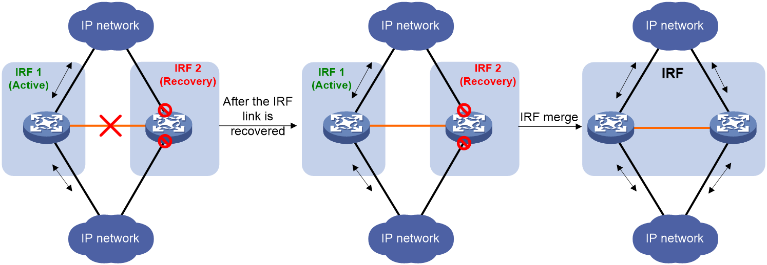
After the failed IRF link between two split IRF fabrics is recovered, log in to the inactive IRF fabric to reboot its member devices if the system requires you to do so. After these member devices join the active IRF fabric as subordinate devices, the IRF merge is complete, as shown in Figure 8. The network interfaces that have been shut down by MAD automatically restore their original state.
|
|
CAUTION: If you inadvertently reboot the active IRF fabric after the failed IRF link recovers, its member devices will join the inactive IRF fabric with their network interfaces shut down by MAD. To restore the original states of the network interfaces in the merged IRF fabric, use the mad restore command. |
|
|
NOTE: If the IRF auto-merge feature is enabled, the inactive IRF member devices will automatically reboot after the failed IRF link recovers and a manual reboot is typically not required. |
Figure 8 Recovering the IRF fabric
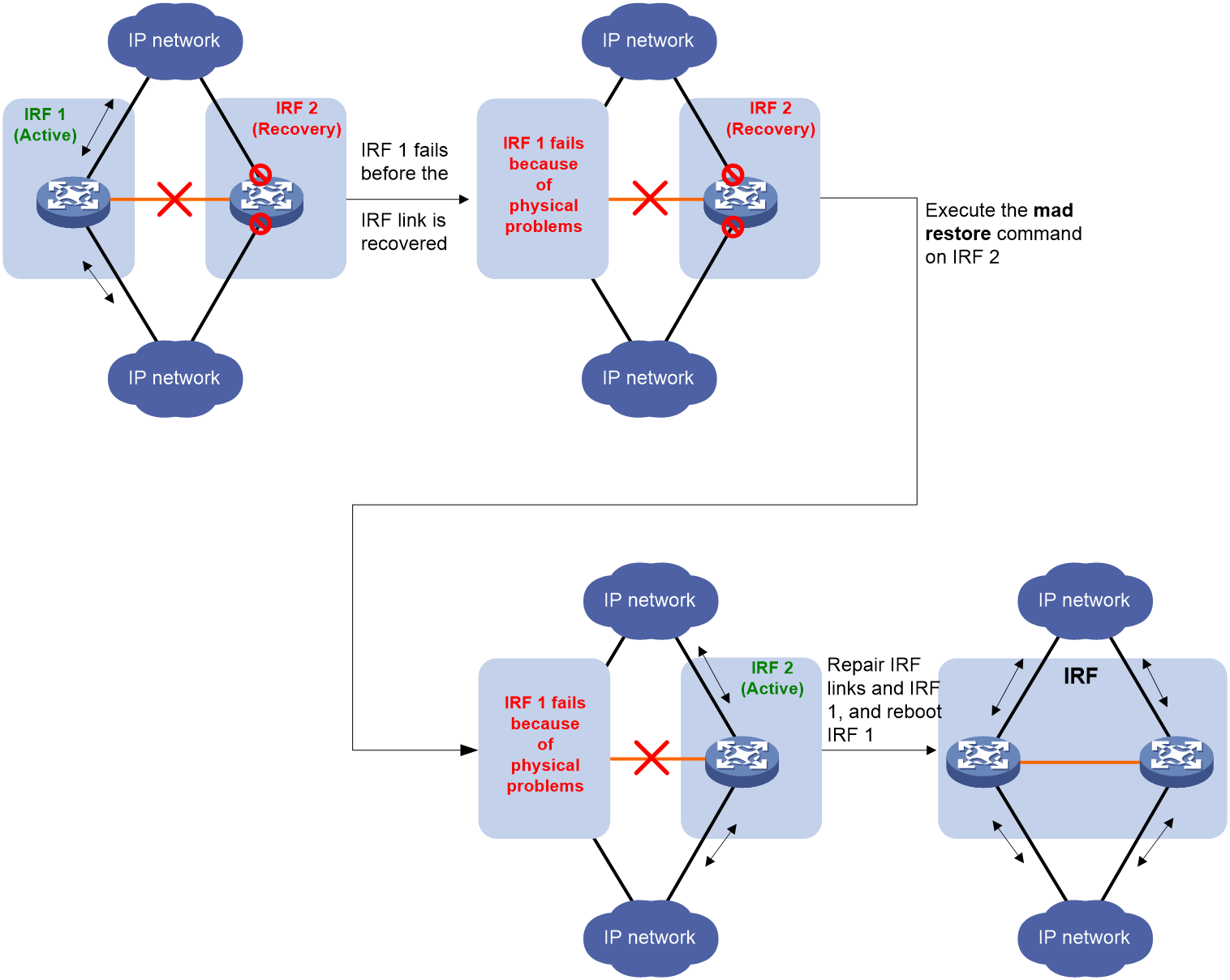
If the active IRF fabric fails before the IRF link is recovered (see Figure 9), use the mad restore command on the inactive IRF fabric to recover the inactive IRF fabric. This command brings up all network interfaces that were shut down by MAD. After the IRF link is repaired, merge the two parts into a unified IRF fabric.
Figure 9 Active IRF fabric fails before the IRF link is recovered
MAD mechanisms
As a best practice, configure a minimum of one MAD mechanism on an IRF fabric.
When you configure multiple MAD mechanisms on an IRF fabric, follow these restrictions and guidelines:
· Do not configure LACP MAD together with ARP MAD or ND MAD, because they handle collisions differently.
· Do not configure BFD MAD together with ARP MAD or ND MAD. BFD MAD handles collisions differently than ARP MAD and ND MAD. In addition, BFD MAD and the spanning tree feature are mutually exclusive, but ARP MAD and ND MAD require the spanning tree feature.
Table 1 compares the MAD mechanisms and their application scenarios.
Table 1 Comparison of MAD mechanisms
|
MAD mechanism |
Advantages |
Disadvantages |
Application scenario |
|
· Detection speed is fast. · No intermediate device is required. · Intermediate device, if used, can come from any vendor. |
· Requires MAD dedicated physical links and Layer 3 interfaces, which cannot be used for transmitting user traffic. · If no intermediate device is used, any two IRF members must have a BFD MAD link to each other. · If an intermediate device is used, every IRF member must have a BFD MAD link to the intermediate device. |
· No special requirements for network scenarios. · If no intermediate device is used, this mechanism is only suitable for IRF fabrics that have a small number of members that are geographically close to one another. For information about BFD, see High Availability Configuration Guide. |
|
|
· No intermediate device is required. · Intermediate device, if used, can come from any vendor. · Does not require MAD dedicated interfaces. |
· Detection speed is slower than BFD MAD and LACP MAD. · The spanning tree feature must be enabled. |
Spanning tree-enabled non-link aggregation IPv4 network scenario. For information about ARP, see Layer 3—IP Services Configuration Guide. |
|
|
· No intermediate device is required. · Intermediate device, if used, can come from any vendor. · Does not require MAD dedicated interfaces. |
· Detection speed is slower than BFD MAD and LACP MAD. · The spanning tree feature must be enabled. |
Spanning tree-enabled non-link aggregation IPv6 network scenario. |
BFD MAD
|
|
IMPORTANT: Support for this feature depends on the device model. This feature is supported only on the default MDC. |
BFD MAD detects multi-active collisions by using BFD.
BFD MAD has the following requirements:
· If an intermediate device is used, each member device must have a BFD MAD link to the intermediate device. If no intermediate device is used, all member devices must have a BFD MAD link to each other.
· Ports on BFD MAD links are assigned to a VLAN or Layer 3 aggregate interface used for BFD MAD. Each member device is assigned a MAD IP address on the VLAN interface or Layer 3 aggregate interface.
The BFD MAD links and BFD MAD VLAN (or Layer 3 aggregate interface) must be dedicated. Do not use BFD MAD links or BFD MAD VLAN (or Layer 3 aggregate interface) for any other purposes.
|
|
NOTE: The MAD addresses identify the member devices and must belong to the same subnet. |
Figure 10 shows a typical BFD MAD scenario that uses an intermediate device. On the intermediate device, assign the ports on the BFD MAD links to the same VLAN.
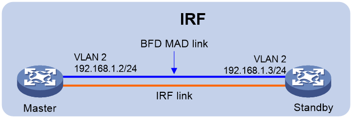
Figure 11 shows a typical BFD MAD scenario that does not use an intermediate device.
With BFD MAD, the master attempts to establish BFD sessions with other member devices by using its MAD IP address as the source IP address.
· If the IRF fabric is integrated, only the MAD IP address of the master takes effect. The master cannot establish a BFD session with any other member. If you execute the display bfd session command, the state of the BFD sessions is Down.
· When the IRF fabric splits, the IP addresses of the masters in the split IRF fabrics take effect. The masters can establish a BFD session. If you execute the display bfd session command, the state of the BFD session between the two devices is Up.
Figure 10 BFD MAD scenario with an intermediate device
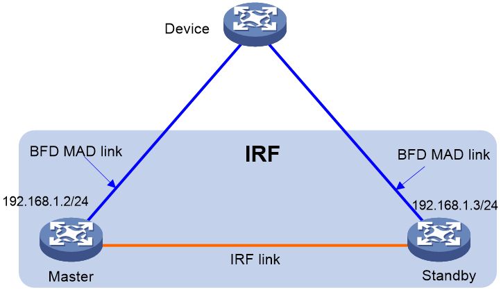
Figure 11 BFD MAD scenario without an intermediate device
ARP MAD
|
|
NOTE: Support for this feature depends on the device model. |
ARP MAD detects multi-active collisions by using extended ARP packets that convey the IRF MAD domain ID and the active ID.
Each IRF member compares the MAD domain ID and the active ID in incoming extended ARP packets with its MAD domain ID and active ID.
· If the MAD domain IDs are different, the extended ARP packet is from a different IRF fabric. The device does not continue to process the packet with the MAD mechanism.
· If the MAD domain IDs are the same, the device compares the active IDs.
¡ If the active IDs are different, the IRF fabric has split.
¡ If the active IDs are the same, the IRF fabric is integrated.
You can configure ARP MAD on a VLAN interface.
If a VLAN interface is used, ARP MAD can work with or without an intermediate device. Make sure the following requirements are met:
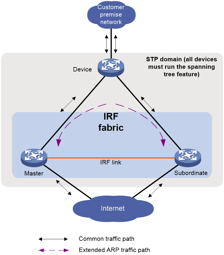
· If an intermediate device is used, connect each IRF member device to the intermediate device, as shown in Figure 12. Run the spanning tree feature between the IRF fabric and the intermediate device. In this situation, data links can be used.
· If no intermediate device is used, connect each IRF member device to all other member devices. In this situation, IRF links cannot be used for ARP MAD.
Figure 12 ARP MAD scenario (VLAN interface)
ND MAD
|
|
NOTE: Support for this feature depends on the device model. |
ND MAD detects multi-active collisions by using NS packets to transmit the IRF MAD domain ID and the active ID.
ND MAD is applicable to IPv6 network scenarios. It uses the same multi-active detection mechanism and topology as ARP MAD.
Restrictions and guidelines: IRF configuration
For a successful IRF setup, follow the restrictions and guidelines in this section and the setup procedure in "IRF tasks at a glance."
Hardware compatibility with IRF
The device can form an IRF fabric only with devices in the same series. Hardware compatibility with IRF varies by device model.
Software requirements for IRF
All IRF member devices must run the same software image version as the master. For software synchronization, make sure the software auto-update feature is enabled. The feature can automatically synchronize the device with the software running on the master if the software versions are different.
You must manually synchronize the software if software auto-update fails to update software. This situation might occur if the IRF fabric cannot identify the software version used on the new device.
For more information, see "Enabling software auto-update for software image synchronization."
IRF fabric size
An IRF fabric can contain a maximum of n member devices. The value for n varies by device model.
IRF topo-domain ID restrictions
To form an IRF fabric, devices must have the same IRF topo-domain ID.
IRF network interfaces
Typically, use high-speed interfaces as IRF network interfaces.
To use an interface as an IRF network interface, use the port group interface command to bind the interface to the IRF port.
The number of channels you can bind to an IRF port depending on the VSR model and the binding method.
· On the VSR1000 router:
¡ If you execute the command without specifying a channel type, you can bind only one hybrid channel to the IRF port.
¡ If you execute the command with a channel type specified, you can bind a maximum of one data channel and one control channel to the IRF port.
· On the VSR2000 router:
¡ If you execute the command without specifying a channel type, you can bind a maximum of two hybrid channels to the IRF port. The channels will operate in active/standby mode.
¡ If you execute the command with a channel type specified, you can bind only one data channel and one control channel to the IRF port.
An IRF port must have a minimum of one hybrid channel or a minimum of one data channel and one control channel.
For interfaces in the same physical port group, you must use all or none of the interfaces for IRF links.
To avoid IRF split, do not use the shutdown command on an IRF network interface if the interface is the only control channel available on the IRF standby device.
Transceiver modules and cables selection for IRF
Support for transceiver modules and cables varies by device model.
For more information about the transceiver modules and cables, see H3C Transceiver Modules User Guide.
|
|
NOTE: The transceiver modules and DAC cables available for the device are subject to change over time. For the most up-to-date list of transceiver modules and DAC cables, contact your H3C sales representative. |
Configuration backup
As a best practice, back up the next-startup configuration file on a device before adding the device to an IRF fabric as a standby device.
A standby device's next-startup configuration file might be overwritten if the master and the standby devices use the same file name for their next-startup configuration files. You can use the backup file to restore the original configuration after removing the standby device from the IRF fabric.
Feature compatibility and configuration restrictions with IRF
System operating mode
All member devices in the IRF fabric must work in the same system operating mode (set by using the system-working-mode command). For more information about the system operating mode, see Fundamentals Configuration Guide.
ACL
To form an IRF fabric, all member devices in the IRF fabric must use the same ACL hardware mode. For more information about hardware-based ACLs, see ACL and QoS Configuration Guide.
Licensing requirements for IRF
For a license-based feature to run correctly on an IRF fabric, make sure the licenses installed for the feature on all member devices are the same. For more information about feature licensing, see Fundamentals Configuration Guide.
IRF tasks at a glance
To configure IRF, perform the following tasks:
a. Assigning a member ID to each IRF member device
b. (Optional.) Specifying a priority for each member device
c. Assigning the same IRF topo-domain ID to the member devices
To form an IRF fabric, devices must have the same IRF topo-domain ID.
d. Assigning links to the IRF port
e. Saving configuration to the next-startup configuration file
f. Connecting IRF network interfaces
g. Setting the operating mode to IRF mode
Configure a minimum of one MAD mechanism on an IRF fabric. For the MAD compatibility, see "MAD mechanism compatibility."
¡ Excluding a network interface from the shutdown action upon detection of multi-active collision
This feature excludes a network interface from the shutdown action for management or other special purposes when an IRF fabric transits to the Recovery state.
3. (Optional.) Optimizing IRF settings for an IRF fabric
¡ Changing the member ID of a member device
¡ Changing the IRF topo-domain ID for the IRF fabric
¡ Adding links to the IRF port
¡ Configuring a member device description
¡ Configuring IRF bridge MAC address settings
¡ Enabling software auto-update for software image synchronization
¡ Removing a member device from the IRF fabric
¡ Adding a removed member device back to the IRF fabric
Planning the IRF fabric setup
Consider the following items when you plan an IRF fabric:
· Hardware compatibility and restrictions.
· IRF fabric size.
· Master device.
· Member ID and priority assignment scheme.
· IRF topology and cabling scheme.
· IRF network interfaces.
Setting up an IRF fabric
Assigning a member ID to each IRF member device
Restrictions and guidelines
Assign a unique IRF member ID to a device before changing the device's operating mode to IRF.
Procedure
1. Enter system view.
system-view
2. Assign an IRF member ID to the device.
irf member member-id
The default member ID is 1.
Specifying a priority for each member device
About this task
IRF member priority represents the possibility for a device to be elected the master in an IRF fabric. The higher the priority, the higher the possibility.
Procedure
1. Enter system view.
system-view
2. Specify a priority for the device.
irf priority priority
The default IRF member priority is 1.
Assigning the same IRF topo-domain ID to the member devices
About this task
To form an IRF fabric, devices must have the same IRF topo-domain ID. IRF topo-domain IDs prevent IRF fabrics from interfering with one another.
Restrictions and guidelines
For a new topo-domain ID to take effect, you must reboot the device.
Procedure
1. Enter system view.
system-view
2. Assign a topo-domain ID to the device.
irf topo-domain topo-domain-id
The default IRF topo-domain ID is 0.
Assigning links to the IRF port
Restrictions and guidelines
In standalone mode, IRF port binding operations do not affect the current configuration of the network interfaces used for IRF links. However, when the operating mode changes to IRF mode, the default configuration is restored on the network interfaces.
Procedure
1. Enter system view.
system-view
2. Enter IRF port view.
irf-port
3. Bind a network interface to the IRF port.
port group interface interface-type interface-number [ type { control | data } ]
By default, no network interfaces are bound to the IRF port.
Repeat this step to assign multiple links to the IRF port.
The channel type of the link is hybrid if you do not specify a channel type.
To change the channel type of an IRF link, you must first remove the binding, and then rebind the link.
Saving configuration to the next-startup configuration file
About this task
Save the running configuration before converting to the IRF mode. A mode change requires a reboot, which causes all unsaved settings to be lost.
Procedure
To save the running configuration to the next-startup configuration file, execute the following command in any view:
save [ safely ] [ backup | main ] [ force ]
For more information about the save command, see configuration file management commands in Fundamentals Command Reference.
Connecting IRF network interfaces
Connect IRF network interfaces based on the cabling scheme and the requirements in "Network topology."
Setting the operating mode to IRF mode
About this task
By default, the device operates in standalone mode. To assign the device to an IRF fabric, you must change its operating mode to IRF mode.
Restrictions and guidelines
The device automatically reboots for the mode change to take effect.
During the reboot, you may choose to have the system automatically convert the startup configuration file. Automatic configuration conversion prevents slot- or interface-related settings from becoming invalid. For example, the system adds member ID information to interface numbers and file paths in IRF mode.
IRF generates packets on a device in IRF mode even if the device does not form an IRF fabric with any other devices. To conserve system resources, set a device to standalone mode after removing it from an IRF fabric. To restore the standalone mode, use the undo chassis convert mode command.
Prerequisites
Before you change the operating mode, verify that a unique IRF member ID has been assigned to the device. If you do not assign a member ID, the device automatically uses the ID of 1 after the mode is changed to IRF.
Procedure
1. Enter system view.
system-view
2. Set the operating mode to IRF mode.
chassis convert mode irf
The default operating mode is standalone mode.
Accessing the IRF fabric
The IRF fabric appears as one device after it is formed. You configure and manage all IRF members from the CLI of the master. All settings you have made are automatically propagated to the IRF members.
The following methods are available for accessing an IRF fabric:
· Local login—Log in through the AUX or console port of any member device.
· Remote login—Log in at a Layer 3 interface on any member device by using methods including Telnet, Web, and SNMP.
Whichever device you connect, you are placed at the CLI or Web-based interface of the master when you log in to the IRF fabric.
For more information, see login configuration in Fundamentals Configuration Guide.
Configuring MAD
Restrictions and guidelines for MAD configuration
MAD mechanism compatibility
When you configure MAD, follow these restrictions and guidelines:
· As a best practice, configure a minimum of one MAD mechanism on an IRF fabric.
· When you configure multiple MAD mechanisms on an IRF fabric, follow these restrictions and guidelines:
¡ Do not configure LACP MAD together with ARP MAD or ND MAD, because they handle collisions differently.
¡ Do not configure BFD MAD together with ARP MAD or ND MAD. BFD MAD handles collisions differently than ARP MAD and ND MAD. In addition, BFD MAD and the spanning tree feature are mutually exclusive, but ARP MAD and ND MAD require the spanning tree feature.
Assigning IRF domain IDs
If LACP MAD, ARP MAD, or ND MAD runs between two IRF fabrics, assign each fabric a unique IRF MAD domain ID. (For BFD MAD, this task is optional.)
An IRF fabric has only one IRF MAD domain ID.
You can change the IRF MAD domain ID by using the following commands: irf domain, mad enable, mad arp enable, or mad nd enable. The IRF MAD domain IDs configured by using these commands overwrite each other.
If you change the IRF MAD domain ID in one MDC, the IRF MAD domain IDs in all other MDCs change automatically. The irf domain command is available only on the default MDC. The mad enable, mad arp enable, and mad nd enable commands are available on any MDCs.
Bringing up network interfaces shut down by MAD
To prevent an interface from being shut down when the IRF fabric transits to the Recovery state, use the mad exclude interface command. To bring up interfaces in a Recovery-state IRF fabric, use the mad restore command instead of the undo shutdown command. The mad restore command activates the Recovery-state IRF fabric.
Configuring BFD MAD
|
|
NOTE: Support for this feature depends on the device model. |
Restrictions and guidelines for BFD MAD configuration
Before you configure BFD MAD, choose a BFD MAD link scheme as described in "BFD MAD."
As a best practice, connect the BFD MAD links after you finish the BFD MAD configuration.
When you configure BFD MAD on a VLAN interface, follow these restrictions and guidelines:
|
Category |
Restrictions and guidelines |
|
BFD MAD VLAN |
· Do not enable BFD MAD on VLAN-interface 1. · If you are using an intermediate device, perform the following tasks: ¡ On the IRF fabric and the intermediate device, create a VLAN for BFD MAD. ¡ On the IRF fabric and the intermediate device, assign the ports of BFD MAD links to the BFD MAD VLAN. ¡ On the IRF fabric, create a VLAN interface for the BFD MAD VLAN. · Make sure the IRF fabrics on the network use different BFD MAD VLANs. · Make sure the BFD MAD VLAN contains only ports on the BFD MAD links. Exclude a port from the BFD MAD VLAN if that port is not on a BFD MAD link. If you have assigned that port to all VLANs by using the port trunk permit vlan all command, use the undo port trunk permit command to exclude that port from the BFD MAD VLAN. |
|
BFD MAD VLAN and feature compatibility |
Do not use the BFD MAD VLAN for any purpose other than configuring BFD MAD. · Use only the mad bfd enable and mad ip address commands on the VLAN interface used for BFD MAD. If you configure other features, both BFD MAD and other features on the interface might run incorrectly. · Disable the spanning tree feature on all Layer 2 Ethernet ports in the BFD MAD VLAN. The MAD feature is mutually exclusive with the spanning tree feature. |
|
MAD IP address |
· To avoid network issues, only use the mad ip address command to configure IP addresses on the BFD MAD-enabled VLAN interface. Do not configure an IP address by using the ip address command or configure a VRRP virtual address on the BFD MAD-enabled VLAN interface. · Make sure all the MAD IP addresses are on the same subnet. |
When you configure BFD MAD on a Layer 3 aggregate interface, follow these restrictions and guidelines :
|
Category |
Restrictions and guidelines |
|
BFD MAD-enabled Layer 3 aggregate interface |
Make sure the IRF fabrics on the network use different aggregate interfaces for BFD MAD. |
|
BFD MAD VLAN |
On the intermediate device (if any), assign the ports on the BFD MAD links to the same VLAN. Do not assign the ports to an aggregate interface. |
|
BFD MAD-enabled Layer 3 aggregate interface and feature compatibility |
Use only the mad bfd enable and mad ip address commands on the BFD MAD-enabled interface. If you configure other features, both BFD MAD and other features on the interface might run incorrectly. |
|
MAD IP address |
· To avoid network issues, only use the mad ip address command to configure IP addresses on the BFD MAD-enabled interface. Do not configure an IP address by using the ip address command or configure a VRRP virtual address on the BFD MAD-enabled interface. · Make sure all the MAD IP addresses are on the same subnet. |
Configuring BFD MAD on a VLAN interface
1. Enter system view.
system-view
2. (Optional.) Assign a MAD domain ID to the IRF fabric.
irf domain domain-id
By default, the MAD domain ID of an IRF fabric is 0.
3. Create a VLAN dedicated to BFD MAD.
vlan vlan-id
By default, only VLAN 1 exists.
4. Return to system view.
quit
5. Enter Ethernet interface view or interface range view.
¡ Enter Ethernet interface view:
interface interface-type interface-number
¡ Enter interface range view. Choose one of the following commands:
interface range interface-list
interface range name name [ interface interface-list ]
For more information about the interface range and interface range name commands, see bulk interface configuration commands in Interface Command Reference.
6. Assign the Ethernet port or the range of Ethernet ports to the BFD MAD VLAN.
¡ Assign the Ethernet ports to the VLAN as access ports:
port access vlan vlan-id
¡ Assign the Ethernet ports to the VLAN as trunk ports:
port trunk permit vlan vlan-id
¡ Assign the Ethernet ports to the VLAN as hybrid ports:
port hybrid vlan vlan-id { tagged | untagged }
The link type of BFD MAD ports can be access, trunk, or hybrid.
The default link type of an Ethernet port is access.
7. Return to system view.
quit
8. Create the VLAN interface and enter VLAN interface view.
interface vlan-interface interface-number
9. Enable BFD MAD.
mad bfd enable
By default, BFD MAD is disabled.
10. Assign a MAD IP address to a member device on the VLAN interface.
mad ip address ip-address { mask | mask-length } member member-id
By default, no MAD IP addresses are configured on a VLAN interface.
Repeat this step to assign a MAD IP address to each member device on the VLAN interface.
Configuring BFD MAD on a Layer 3 aggregate interface
1. Enter system view.
system-view
2. (Optional.) Assign a MAD domain ID to the IRF fabric.
irf domain domain-id
By default, the MAD domain ID of an IRF fabric is 0.
3. Create a Layer 3 aggregate interface for BFD MAD.
interface route-aggregation interface-number
4. Return to system view.
quit
5. Enter interface view or interface range view.
¡ Enter Ethernet interface view.
interface interface-type interface-number
¡ Enter interface range view. Choose one of the following commands:
interface range interface-list
interface range name name [ interface interface-list ]
For more information about the interface range and interface range name commands, see bulk interface configuration commands in Interface Command Reference.
6. Assign the port or the range of ports to the aggregation group for the aggregate interface.
port link-aggregation group number
7. Return to system view.
quit
8. Enter Layer 3 aggregate interface view.
interface route-aggregation interface-number
9. Enable BFD MAD.
mad bfd enable
By default, BFD MAD is disabled.
10. Assign a MAD IP address to a member device on the Layer 3 aggregate interface.
mad ip address ip-address { mask | mask-length } member member-id
By default, no MAD IP addresses are configured on aggregate interfaces.
Repeat this step to assign a MAD IP address to each member device on the aggregate interface.
Configuring ARP MAD
|
|
NOTE: Support for this feature depends on the device model. |
Restrictions and guidelines for ARP MAD configuration
When you configure ARP MAD on a VLAN interface, follow these restrictions and guidelines:
|
Category |
Restrictions and guidelines |
|
ARP MAD VLAN |
· Do not enable ARP MAD on VLAN-interface 1. · If you are using an intermediate device, perform the following tasks: ¡ On the IRF fabric and the intermediate device, create a VLAN for ARP MAD. ¡ On the IRF fabric and the intermediate device, assign the ports of ARP MAD links to the ARP MAD VLAN. ¡ On the IRF fabric, create a VLAN interface for the ARP MAD VLAN. · Do not use the ARP MAD VLAN for any other purposes. |
|
ARP MAD and feature configuration |
If an intermediate device is used, make sure the following requirements are met: · Run the spanning tree feature between the IRF fabric and the intermediate device to ensure that there is only one ARP MAD link in forwarding state. For more information about the spanning tree feature and its configuration, see Layer 2—LAN Switching Configuration Guide. · Enable the IRF fabric to change its bridge MAC address as soon as the address owner leaves. · If the intermediate device is also an IRF fabric, assign the two IRF fabrics different MAD domain IDs for correct split detection. |
When you configure ARP MAD on a Reth interface, follow these restrictions and guidelines:
|
Category |
Restrictions and guidelines |
|
ARP MAD-enabled Reth interface |
Make sure each member device has a network interface assigned to the Reth interface. |
|
ARP MAD and feature configuration |
· Enable the IRF fabric to change its bridge MAC address as soon as the address owner leaves. · If an intermediate device is also an IRF fabric, assign the two IRF fabrics different MAD domain IDs for correct split detection. |
Configuring ARP MAD on a VLAN interface
1. Enter system view.
system-view
2. Assign a MAD domain ID to the IRF fabric.
irf domain domain-id
The default IRF MAD domain ID is 0.
3. Configure the IRF bridge MAC address to change as soon as the address owner leaves.
undo irf mac-address persistent
By default, the IRF bridge MAC address does not change after the address owner leaves the fabric.
4. Create a VLAN dedicated to ARP MAD.
vlan vlan-id
By default, only VLAN 1 exists.
5. Return to system view.
quit
6. Enter Ethernet interface view or interface range view.
¡ Enter Ethernet interface view.
interface interface-type interface-number
¡ Enter interface range view. Choose one of the following commands:
interface range interface-list
interface range name name [ interface interface-list ]
For more information about the interface range and interface range name commands, see bulk interface configuration commands in Interface Command Reference.
7. Assign the port or the range of ports to the ARP MAD VLAN.
¡ Assign the ports to the VLAN as access ports.
port access vlan vlan-id
¡ Assign the ports to the VLAN as trunk ports.
port trunk permit vlan vlan-id
¡ Assign the ports to the VLAN as hybrid ports.
port hybrid vlan vlan-id { tagged | untagged }
The link type of ARP MAD ports can be access, trunk, or hybrid.
The default link type of a port is access.
8. Return to system view.
quit
9. Enter VLAN interface view.
interface vlan-interface interface-number
10. Assign the interface an IP address.
ip address ip-address { mask | mask-length }
By default, no IP addresses are assigned to a VLAN interface.
11. Enable ARP MAD.
mad arp enable
By default, ARP MAD is disabled.
Configuring ARP MAD on a Reth interface
1. Enter system view.
system-view
2. Assign a MAD domain ID to the IRF fabric.
irf domain domain-id
The default IRF MAD domain ID is 0.
3. Configure the IRF bridge MAC address to change as soon as the address owner leaves.
undo irf mac-address persistent
By default, the IRF bridge MAC address does not change after the address owner leaves the fabric.
4. Create a Reth interface and enter Reth interface view.
interface reth interface-number
By default, no Reth interfaces exist.
If the Reth interface is already created, this command directly enters the Reth interface view.
5. Assign member interfaces to the Reth interface.
member interface interface-type interface-number priority priority
By default, a Reth interface does not have member interfaces.
6. Enable ARP MAD.
mad arp enable
By default, ARP MAD is disabled.
7. Assign an IP address to the Reth interface.
ip address ip-address { mask | mask-length }
By default, no IP addresses are configured on a Reth interface.
Configuring ND MAD
|
|
NOTE: Support for this feature depends on the device model. |
Restrictions and guidelines for ND MAD configuration
When you configure ND MAD on a VLAN interface, follow these restrictions and guidelines:
|
Category |
Restrictions and guidelines |
|
ND MAD VLAN |
· Do not enable ND MAD on VLAN-interface 1. · If you are using an intermediate device, perform the following tasks: ¡ On the IRF fabric and the intermediate device, create a VLAN for ND MAD. ¡ On the IRF fabric and the intermediate device, assign the ports of ND MAD links to the ND MAD VLAN. ¡ On the IRF fabric, create a VLAN interface for the ND MAD VLAN. · Do not use the ND MAD VLAN for any other purposes. |
|
ND MAD and feature configuration |
If an intermediate device is used, make sure the following requirements are met: · Run the spanning tree feature between the IRF fabric and the intermediate device to ensure that there is only one ND MAD link in forwarding state. For more information about the spanning tree feature and its configuration, see Layer 2—LAN Switching Configuration Guide. · Enable the IRF fabric to change its bridge MAC address as soon as the address owner leaves. · If the intermediate device is also an IRF fabric, assign the two IRF fabrics different MAD domain IDs for correct split detection. |
Configuring ND MAD on a VLAN interface
1. Enter system view.
system-view
2. Assign a MAD domain ID to the IRF fabric.
irf domain domain-id
The default IRF MAD domain ID is 0.
3. Configure the IRF bridge MAC address to change as soon as the address owner leaves.
undo irf mac-address persistent
By default, the IRF bridge MAC address does not change after the address owner leaves the fabric.
4. Create a VLAN dedicated to ND MAD.
vlan vlan-id
By default, only VLAN 1 exists.
5. Return to system view.
quit
6. Enter Ethernet interface view or interface range view.
¡ Enter Ethernet interface view.
interface interface-type interface-number
¡ Enter interface range view. Choose one of the following commands:
interface range interface-list
interface range name name [ interface interface-list ]
For more information about the interface range and interface range name commands, see bulk interface configuration commands in Interface Command Reference.
7. Assign the port or the range of ports to the ND MAD VLAN.
¡ Assign the ports to the VLAN as access ports.
port access vlan vlan-id
¡ Assign the ports to the VLAN as trunk ports.
port trunk permit vlan vlan-id
¡ Assign the ports to the VLAN as hybrid ports.
port hybrid vlan vlan-id { tagged | untagged }
The link type of ND MAD ports can be access, trunk, or hybrid.
The default link type of a port is access.
8. Return to system view.
quit
9. Enter VLAN interface view.
interface vlan-interface interface-number
10. Assign the interface an IPv6 address.
ipv6 address { ipv6-address/prefix-length | ipv6-address prefix-length }
By default, no IPv6 addresses are assigned to a VLAN interface.
11. Enable ND MAD.
mad nd enable
By default, ND MAD is disabled.
Configuring ND MAD on a Reth interface
1. Enter system view.
system-view
2. Assign a MAD domain ID to the IRF fabric.
irf domain domain-id
The default IRF MAD domain ID is 0.
3. Configure the IRF bridge MAC address to change as soon as the address owner leaves.
undo irf mac-address persistent
By default, the IRF bridge MAC address does not change after the address owner leaves the fabric.
4. Create a Reth interface and enter Reth interface view.
interface reth interface-number
By default, no Reth interfaces exist.
If the Reth interface is already created, this command directly enters the Reth interface view.
5. Assign member interfaces to the Reth interface.
member interface interface-type interface-number priority priority
By default, a Reth interface does not have member interfaces.
6. Enable ND MAD.
mad nd enable
By default, ND MAD is disabled.
7. Assign an IPv6 address to the Reth interface.
ipv6 address { ipv6-address/prefix-length | ipv6-address prefix-length }
By default, no IPv6 addresses are configured on a Reth interface.
Excluding a network interface from the shutdown action upon detection of multi-active collision
About this task
When an IRF fabric transits to the Recovery state, the system automatically shuts down all network interfaces except for the interfaces bound to IRF ports.
You can exclude a network interface from the shutdown action for management or other special purposes. For example:
· Exclude an interface from the shutdown action so you can Telnet to the interface for managing the device.
· Exclude a VLAN interface and its Layer 2 Ethernet ports from the shutdown action so you can log in through the VLAN interface.
Restrictions and guidelines
When you configure this feature, follow these restrictions and guidelines:
· If the Layer 2 Ethernet ports of a VLAN interface are distributed on multiple member devices, the exclusion operation might introduce IP collision risks. The VLAN interface might be up on both active and inactive IRF fabrics.
· Do not exclude the following interfaces from the shutdown action:
¡ Aggregate interfaces used for MAD and their member interfaces.
¡ VLAN interfaces used for MAD and its Ethernet ports.
¡ Reth interfaces used for MAD and their member interfaces.
Procedure
1. Enter system view.
system-view
2. Configure a network interface to not shut down when the IRF fabric transits to the Recovery state.
mad exclude interface interface-type interface-number
By default, all network interfaces on a Recovery-state IRF fabric are shut down, except for the IRF network interfaces.
Recovering an IRF fabric
About this task
If the active IRF fabric fails before the IRF link is recovered, perform this task on the inactive IRF fabric to recover the inactive IRF fabric for traffic forwarding. The manual recovery operation brings up all network interfaces that were shut down by MAD on the inactive IRF fabric.
Procedure
1. Enter system view.
system-view
2. Recover the inactive IRF fabric.
mad restore
Optimizing IRF settings for an IRF fabric
Changing the member ID of a member device
Restrictions and guidelines
In IRF mode, an IRF member ID change can invalidate member ID-related settings and cause data loss. Make sure you fully understand its impact on your live network.
To create an IRF fabric, you must assign a unique IRF member ID to each member device.
To prevent any undesirable configuration change or data loss, avoid changing member IDs after the IRF fabric is formed.
The new member ID takes effect at reboot. After the device reboots, the settings on all member ID-related resources (including network interfaces) are removed, regardless of whether you have saved the configuration.
Procedure
1. Enter system view.
system-view
2. Change the member ID of a member device.
irf member member-id renumber new-member-id
By default, the device uses the member ID that is set in standalone mode.
3. Return to user view.
quit
4. Save the running configuration.
save
5. Reboot the member device.
reboot
Changing the IRF topo-domain ID for the IRF fabric
Restrictions and guidelines
For the topo-domain ID to take effect, you must reboot the IRF fabric.
Procedure
1. Enter system view.
system-view
2. Change the topo-domain ID of the IRF fabric.
irf topo-domain topo-domain-id
By default, an IRF fabric uses the topo-domain ID that is set on member devices in standalone mode.
3. Return to user view.
quit
4. Save the running configuration.
save
5. Reboot the IRF fabric.
reboot
Adding links to the IRF port
About this task
Use this feature to modify IRF port bindings after the IRF fabric is formed. You can add links to an IRF port without traffic interruption on the IRF port.
Restrictions and guidelines
When you perform this task, follow the IRF port binding restrictions and configuration guidelines.
Procedure
1. Enter system view.
system-view
2. Enter Ethernet interface view or interface range view.
¡ Enter interface view.
interface interface-type interface-number
¡ Enter interface range view. Choose one of the following commands:
interface range interface-list
interface range name name [ interface interface-list ]
For more information about the interface range and interface range name commands, see bulk interface configuration commands in Interface Command Reference.
3. Shut down the network interfaces.
shutdown
The default for this command varies by device model.
4. Return to system view.
quit
5. Enter IRF port view.
irf-port member-id
Each member device has only one IRF port. The port index is the IRF member ID.
6. Bind a network interface to the IRF port.
port group interface interface-type interface-number [ type { control | data } ]
By default, no network interfaces are bound to the IRF port.
Repeat this step to assign multiple links to the IRF port.
The channel type of the link is hybrid if you do not specify a channel type.
To change the channel type of an IRF link, you must first remove the binding, and then rebind the link.
7. Return to system view.
quit
8. Enter Ethernet interface view or interface range view.
¡ Enter interface view.
interface interface-type interface-number
¡ Enter interface range view. Choose one of the following commands:
interface range interface-list
interface range name name [ interface interface-list ]
For more information about the interface range and interface range name commands, see bulk interface configuration commands in Interface Command Reference.
9. Bring up the network interfaces.
undo shutdown
10. Return to system view.
quit
11. Save the running configuration.
save
Activating IRF port settings causes IRF merge and reboot. To avoid data loss, save the running configuration to the startup configuration file before you perform the operation.
12. Activate the configuration on the IRF port.
irf-port-configuration active
After this step is performed, the state of the IRF port changes to UP. The member devices elect a master, and the standby devices automatically reboot to complete the IRF establishment.
After the IRF fabric is formed, you can add links to the IRF port (in UP state) without repeating this step.
This step is optional for the devices that require a reboot for the port group interface to take effect.
Enabling IRF auto-merge
About this task
When two IRF fabrics merge, a member device must reboot to complete the merge if it is in the IRF fabric that fails in master election.
· If the auto-merge feature is enabled, the reboot is automatically performed.
· If the auto-merge feature is disabled, you must reboot the member devices manually.
Procedure
1. Enter system view.
system-view
2. Enable IRF auto-merge.
irf auto-merge enable
By default, this feature is enabled.
Configuring a member device description
About this task
You can configure a description for a member device to easily identify and manage the member device.
Procedure
1. Enter system view.
system-view
2. Configure a description for a member device.
irf member member-id description text
By default, no description is configured for a member device.
Configuring IRF bridge MAC address settings
|
|
NOTE: Support for specifying a MAC address as the IRF bridge MAC address depends on the device model. |
About this task
The bridge MAC address of a system must be unique on a switched LAN. IRF bridge MAC address identifies an IRF fabric by Layer 2 protocols (for example, LACP) on a switched LAN.
By default, an IRF fabric uses the bridge MAC address of the master as the IRF bridge MAC address. After the master leaves, the IRF bridge MAC address persists for a period of time or permanently depending on the IRF bridge MAC persistence setting. When the IRF bridge MAC persistence timer expires, the IRF fabric uses the bridge MAC address of the current master as the IRF bridge MAC address.
In special occasions that require a fixed special IRF bridge MAC address, you can specify that MAC address as the IRF bridge MAC address. For example, when you replace an IRF fabric as a whole, you can configure the new IRF fabric with the IRF bridge MAC address of the existing IRF fabric before the replacement to minimize service interruption.
The IRF bridge MAC persistence setting does not take effect on the manually specified IRF bridge MAC address.
The following is how IRF handles the IRF bridge MAC address if IRF fabrics merge:
· When IRF fabrics merge, IRF ignores the IRF bridge MAC address and checks the bridge MAC address of each member device in the IRF fabrics. IRF merge fails if any two member devices have the same bridge MAC address.
· After IRF fabrics merge, the merged IRF fabric uses the bridge MAC address of the merging IRF fabric that won the master election as the IRF bridge MAC address.
Restrictions and guidelines for IRF bridge MAC address configuration
|
|
CAUTION: Bridge MAC address changes cause transient traffic disruption. |
When you configure IRF bridge MAC persistence, follow these restrictions and guidelines:
· The IRF bridge MAC persistence setting does not take effect if an IRF bridge MAC address is manually specified.
· If ARP MAD or ND MAD is used with the spanning tree feature, you must disable IRF bridge MAC persistence by using the undo irf mac-address persistent command. In addition, do not specify a MAC address as the IRF bridge MAC address.
· If TRILL is used, configure IRF bridge MAC persistence by using the irf mac-address persistent always command or specify a MAC address as the IRF bridge MAC address. The setting avoids unnecessary traffic disruption caused by IRF bridge MAC address changes on the TRILL network.
· If the IRF fabric has multimember aggregate links, do not use the undo irf mac-address persistent command. Use of this command might cause traffic disruption.
Specifying a MAC address as the IRF bridge MAC address
1. Enter system view.
system-view
2. Specify a MAC address as the IRF bridge MAC address.
irf mac-address mac-address
By default, an IRF fabric uses the bridge MAC address of the master as the IRF bridge MAC address.
If an IRF fabric splits after you configure the IRF bridge MAC address, both the split IRF fabrics use the configured bridge MAC address as the IRF bridge MAC address.
Configuring IRF bridge MAC persistence
1. Enter system view.
system-view
2. Configure IRF bridge MAC persistence.
¡ Retain the bridge MAC address permanently even if the address owner has left the IRF fabric:
irf mac-address persistent always
¡ Retain the bridge MAC address for 6 minutes after the address owner leaves the IRF fabric:
irf mac-address persistent timer
This command avoids unnecessary bridge MAC address changes caused by device reboot, transient link failure, or purposeful link disconnection.
¡ Change the bridge MAC address as soon as the address owner leaves the IRF fabric: undo irf mac-address persistent
By default, the IRF bridge MAC address does not change after the address owner leaves the fabric.
Enabling software auto-update for software image synchronization
About this task
The software auto-update feature automatically synchronizes the current software images of the master to devices that are attempting to join the IRF fabric.
To join an IRF fabric, a device must use the same software images as the master in the IRF fabric.
When you add a device to the IRF fabric, software auto-update compares the startup software images of the device with the current software images of the IRF master. If the two sets of images are different, the device automatically performs the following operations:
1. Downloads the current software images of the master.
2. Sets the downloaded images as its main startup software images.
3. Reboots with the new software images to rejoin the IRF fabric.
You must manually update the new device with the software images running on the IRF fabric if software auto-update is disabled.
Restrictions and guidelines
To ensure a successful software auto-update in a multi-user environment, prevent anyone from rebooting or swapping member devices during the auto-update process. To inform administrators of the auto-update status, configure the information center to output the status messages to configuration terminals (see Network Management and Monitoring Configuration Guide).
Make sure the device you are adding to the IRF fabric has sufficient storage space for the new software images.
If sufficient storage space is not available, the device automatically deletes the current software images. If the reclaimed space is still insufficient, the device cannot complete the auto-update. You must reboot the device, and then access the BootWare menu to delete files.
Procedure
1. Enter system view.
system-view
2. Enable software auto-update.
irf auto-update enable
By default, software auto-update is enabled.
Removing a member device from the IRF fabric
About this task
For troubleshooting or maintenance purposes, you can remove a member device from an IRF fabric by disabling the member device's multimember stacking capability. The device will be removed from the IRF fabric 5 seconds after you disable its multimember stacking capability.
The removed member device still operates in IRF mode and runs the original IRF settings. However, it does not send or receive IRF control packets.
Restrictions and guidelines
The removed IRF member might have the same Layer 2 or Layer 3 settings as the IRF fabric, for example, the IP address and bridge MAC address. To avoid network collisions, change these settings on the removed member or on the IRF fabric.
Procedure
1. Enter system view.
system-view
2. Disable multimember stacking capability for the member device.
undo irf member member-id stack enable
By default, multimember stacking capability is enabled for an IRF member device.
Adding a removed member device back to the IRF fabric
1. Log in to the removed device.
2. Enter system view.
system-view
3. Enable multimember stacking capability for the device.
irf member member-id stack enable
4. Return to user view.
quit
5. Save the running configuration.
save
6. Reboot the device for the setting to take effect.
reboot
The device will rejoin the IRF fabric after the reboot.
Display and maintenance commands for IRF
Execute display commands in any view.
|
Task |
Command |
|
Display information about all IRF members. |
display irf |
|
Display IRF link information. |
display irf link |
|
Display the IRF configuration. |
display irf configuration |
|
Display MAD information. |
display mad [ verbose ] |
IRF configuration examples
Example: Setting up an IRF fabric
Network configuration
As shown in Figure 13, set up a two-member IRF fabric and use ARP MAD to handle multi-active collisions.
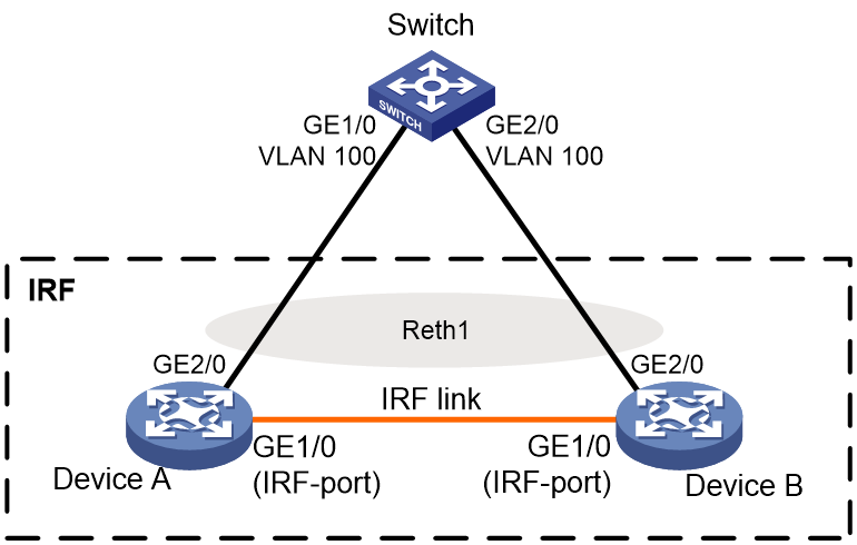
Procedure
1. Make sure Device A and Device B have Layer 2 connectivity between the interfaces to be used for IRF links. (Details not shown.)
2. Configure Device A:
# Change the IRF topo-domain ID to 3 and bind GigabitEthernet 1/1/0 to the IRF port as a hybrid channel.
<DeviceA> system-view
[DeviceA] irf topo-domain 3
The configuration will take effect at the next startup.
[DeviceA] interface gigabitethernet 1/1/0
[DeviceA-GigabitEthernet1/1/0] shutdown
[DeviceA-GigabitEthernet1/1/0] quit
[DeviceA] irf port
[DeviceA-irf-port] port group interface gigabitethernet 1/1/0
[DeviceA-irf-port] quit
[DeviceA] interface gigabitethernet 1/1/0
[DeviceA-GigabitEthernet1/1/0] undo shutdown
[DeviceA-GigabitEthernet1/1/0] quit
# Configure the member priority of Device A as 2.
[DeviceA] irf priority 2
# Enable IRF mode.
[DeviceA] chassis convert mode irf
The device will switch to IRF mode and reboot.
You are recommended to save the current running configuration and specify the configuration file for the next startup. Continue? [Y/N]:y
Do you want to convert the content of the next startup configuration file flash:/startup.cfg to make it available in IRF mode? [Y/N]:y
Now rebooting, please wait...
3. Configure Device B:
# Change the member ID of Device B to 2 and the topo-domain ID to 3.
<DeviceB> system-view
[DeviceB] irf member 2
[DeviceB] irf topo-domain 3
The configuration will take effect at the next startup.
# Bind GigabitEthernet 1/1/0 to the IRF port as a hybrid channel.
[DeviceB] interface gigabitethernet 1/1/0
[DeviceB-GigabitEthernet1/1/0] shutdown
[DeviceB-GigabitEthernet1/1/0] quit
[DeviceB] irf-port
[DeviceB-irf-port] port group interface gigabitethernet 1/1/0
[DeviceB-irf-port] quit
[DeviceB] interface gigabitethernet 1/1/0
[DeviceB-GigabitEthernet1/1/0] undo shutdown
[DeviceB-GigabitEthernet1/1/0] quit
# Enable IRF mode on Device B.
[DeviceB] chassis convert mode irf
The device will switch to IRF mode and reboot.
You are recommended to save the current running configuration and specify the configuration file for the next startup. Continue? [Y/N]:y
Do you want to convert the content of the next startup configuration file flash:/startup.cfg to make it available in IRF mode? [Y/N]:y
Now rebooting, please wait...
The member ID of Device B changes to 2 after the device reboots. The two devices perform master election, and the one that has lost the election reboots to form an IRF fabric with the master.
4. Change the name of the IRF fabric.
<DeviceA> system-view
[DeviceA] system-name IRF
5. Configure ARP MAD:
# Set the MAD domain ID of the IRF fabric to 3.
[IRF] irf domain 3
# Create Reth interface Reth 1, and assign GigabitEthernet 1/2/0 and GigabitEthernet 2/2/0 to the interface.
[IRF] interface reth 1
[IRF-Reth1] member interface gigabitethernet 1/2/0 priority 100
[IRF-Reth1] member interface gigabitethernet 2/2/0 priority 80
# Enable ARP MAD on the Reth interface.
[IRF-Reth1] mad arp enable
You need to assign a domain ID (range: 0-4294967295)
[Current domain is: 3]:
The assigned domain ID is: 3
[IRF-Reth1] quit
6. Configure the switch as the intermediate device for ARP MAD:
|
|
CAUTION: If the intermediate device is also in an IRF fabric, assign the two IRF fabrics different MAD domain IDs for correct split detection. False detection causes IRF split. |
# Create VLAN 100.
<Switch> system-view
[Switch] vlan 100
# Assign GigabitEthernet 1/0/1 and GigabitEthernet 1/0/2 to VLAN 100 for forwarding ARP MAD packets and data packets.
[Switch-vlan100] port gigabitethernet 1/0 gigabitethernet 2/0
[Switch-vlan100] quit
Verifying the configuration
# Display IRF information. Verify that the master is Device A.
[IRF] display irf
Member ID Role Priority CPU MAC Description
*1 Master 2 50da-0051-2608 ---
+2 Standby 1 50da-0051-2670 ---
--------------------------------------------------
The asterisk (*) indicates the master.
The plus sign (+) indicates the device through which you are logged in.
The right angle bracket (>) indicates the device's stack capability is disabled.
Bridge MAC of the IRF: 50da-0051-2608
Auto upgrade : Enabled
MAC persistence : 6 min
Topo-domain ID : 3
Auto merge : Enabled
# Display IRF link information. Verify that IRF links are up.
[IRF] display irf link
Member ID Member Interfaces Status
1 GE1/1/0(ctrl&data) Up
2 GE2/1/0(ctrl&data) Up
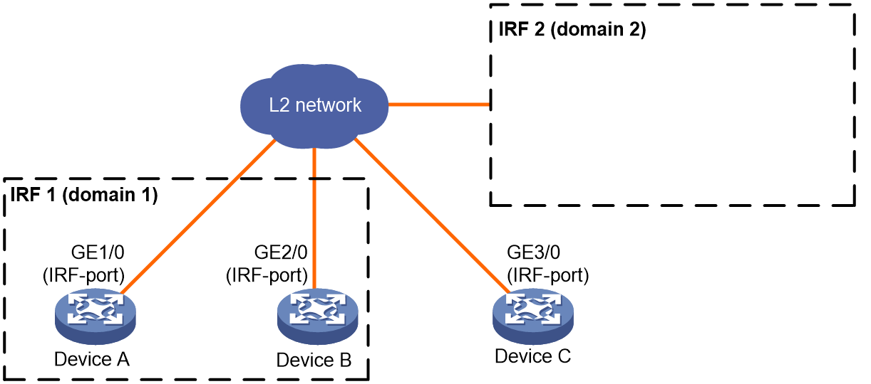
Example: Migrating an IRF member device
Network configuration
As shown in Figure 14, migrate Device C from IRF fabric 1 to IRF fabric 2.
Procedure
1. Configure IRF fabric 1:
# Log in to IRF fabric 1 and identify the member ID of Device C.
<Sysname> display irf
Member ID Role Priority CPU MAC Description
*+1 Master 2 000c-298f-04bb ---
2 Standby 1 000c-2925-4ae1 ---
3 Standby 1 000c-2925-4ae2 ---
---------------------------------------------------
The asterisk (*) indicates the master.
The plus sign (+) indicates the device through which you are logged in.
The right angle bracket (>) indicates the device's stack capability is disabled.
Bridge MAC of the IRF: 7425-8ae3-f48f
Auto upgrade : Enabled
MAC persistence : 6 min
Topo-domain ID : 0
Auto merge : Enabled
# Remove Device C from IRF fabric 1.
<Sysname> system-view
[Sysname] undo irf member 3 stack enable
Member 3 will leave from the IRF and cannot form an IRF with any other devices. Continue? [Y/N]: Y
Operation succeeded. Please check the configuration on member 3 with the IRF for configuration collisions.
2. Configure Device C:
# Log in to Device C and change its IRF topo-domain ID to 2 (the topo-domain ID of IRF 2).
<Sysname> system-view
[Sysname] irf topo-domain 2
The configuration will take effect at the next startup.
# Add Device C to IRF fabric 2.
<Sysname> system-view
[Sysname] irf member 3 stack enable
Please save the configuration, and then reboot the device for the configuration to take effect.
[Sysname] quit
<Sysname> reboot
Start to check configuration with next startup configuration file, please wait..
.......DONE!
Current configuration may be lost after the reboot, save current configuration?
[Y/N]:y
Please input the file name(*.cfg)[flash:/startup.cfg]
(To leave the existing filename unchanged, press the enter key):
flash:/startup.cfg exists, overwrite? [Y/N]:y
Validating file. Please wait...
Saved the current configuration to mainboard device successfully.
This command will reboot the device. Continue? [Y/N]:y
Verifying the configuration
# Log in to IRF fabric 2. (Details not shown.)
# Verify that Device C has joined IRF fabric 2.
<Sysname> display irf