- Table of Contents
- Related Documents
-
| Title | Size | Download |
|---|---|---|
| 01-Text | 649.65 KB |
Power module overview
|
Feature |
Description |
|
Protection |
Protection against over-current input, undervoltage input, overvoltage output, overcurrent output, output short circuit, and overtemperature. |
|
Redundancy |
The power modules can operate in redundant mode, and support load sharing. |
|
Hot swapping |
You can replace a power module when the switch is operating. |
Technical specifications
|
Item |
Specifications |
|
Rated input voltage |
· 100 VAC to 240 VAC @ 50 Hz or 60 Hz (AC input) · 240 VDC (high voltage DC input) |
|
Maximum input current |
· 13 A @ 110 VAC · 9 A @ 220 VAC |
|
Output voltage |
–56 V |
|
Output current |
· 32.2 A (201 VAC to 240 VAC input voltage) · 19.6 A (100 VAC to 200 VAC input voltage) · 32.2 A (240 VDC input voltage) |
|
Maximum output power |
· 1800 W (201 VAC to 240 VAC input voltage) · 1100 W (100 VAC to 200 VAC input voltage) · 1800 W (240 VDC input voltage) |
|
Dimensions (H × W × D) |
40.1 × 82.6 × 297.7 mm (1.58 × 3.25 × 11.72 in) |
|
Operating temperature |
–10°C to +55°C (14°F to 131°F) |
|
Relative humidity |
5% to 95% |
|
|
NOTE: When the input voltage is in the range of 100 VAC to 200 VAC, the output power of the power module decreases to 1100 W. You need to determine whether the output power meets the requirements for the device operation. If not, take necessary measures. For more information, see device installation manuals. |
Appearance
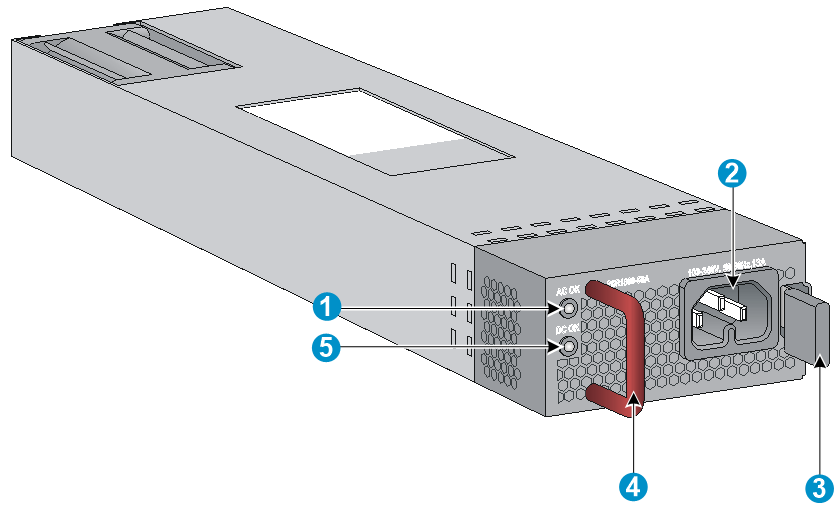
Figure 1 PSR1800-56A
|
(1) Input status LED (AC OK) |
(2) AC input socket |
|
(3) Latch |
|
|
(4) Handle (The handle is in red, indicating the air ventilation is performed by exhausting air from the inside to the outside.) |
|
|
(5) Output status LED (DC OK) |
|
LEDs
|
LED |
Status |
Description |
|
Input status LED (AC OK) |
Steady green |
The power input is normal. |
|
Off |
No power input or the power input is abnormal. |
|
|
Output status LED (DC OK) |
Steady green |
The power output is normal. |
|
Steady red |
The power output is abnormal. |
|
|
Off |
No power output. |
Installing and removing a power module
Safety precautions
To avoid possible bodily injury and power module and device damage, follow these safety precautions:
· When you install and remove a power module, always wear an ESD wrist strap and make sure it makes good skin contact and is well grounded.
· Before you install the power module, make sure the voltage of the power source is the same as the rated voltage of the power module, and the output voltage of the power module is the same as the required voltage.
· Do not touch any naked cable or terminal of the power module.
· Do not place the power module in a wet area, and prevent liquid from flowing into the power module.
· To avoid power module damage, do not open the power module. When the internal circuits or components of the power module fail, contact the maintainer for examining and repairing.
Tools
Prepare an ESD wrist strap and a flat-blade screwdriver yourself.
Installing and removing a power module
|
|
IMPORTANT: Before installation, make sure the power module model is as required. For more information about the device requirements, see the installation guide of the device. |
Installing the power module
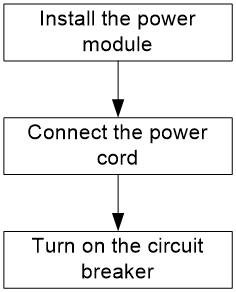
To avoid bodily injury or device damage, follow the steps in Figure 2 to install the power module.
Figure 2 Installation procedure
1. Wear an ESD wrist strap and make sure the strap makes good skin contact and is reliably grounded.
2. Unpack the power module and verify that the power module model is as required.
3. As shown in Figure 3, with the upside of the power module up, hold the handle of the power module with one hand and the bottom of the power module with the other, and then slide the power module slowly along the guide rails into the slot. When the power module is completely inserted into the slot, you can hear that the latch of the power module clicks into the slot.
Figure 3 Installing the power module
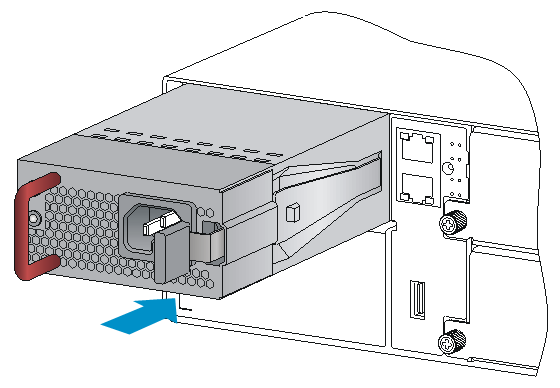
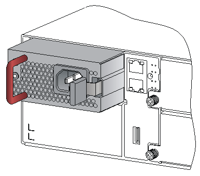
Figure 4 Appearance of the power module after installation
|
|
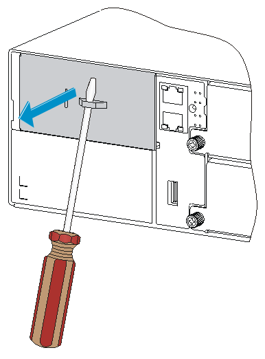
IMPORTANT: · To avoid damaging or bending the terminals of the power module, if the insertion direction is incorrect during the installation, you must pull the power module out, adjust the direction, and insert it again. · To remove the filler panel (if any) from the power module slot on the device, insert a flat-blade screwdriver through the handle and pull the filler panel outward along the guide rails, as shown in Figure 5. · Keep the filler panel and the packaging box and packaging bag of the power module for future use. |
Figure 5 Removing the filler panel
Connecting the AC power cord
|
|
CAUTION: · The PSR1800-56A power module must use the high-temperature resistant C15 connector power cord delivered with the power module. · Turn off the circuit breaker before connecting the power cord. |
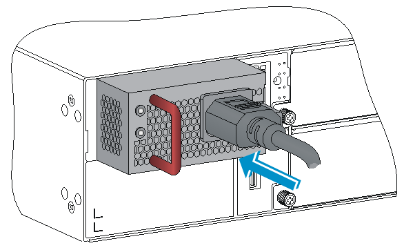
1. As shown in Figure 6, plug the female connector end of the AC power cord into the AC input socket on the switch.
Figure 6 Connecting the AC power cord
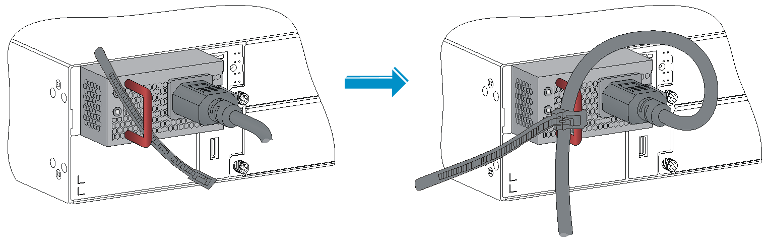
2. As shown in Figure 7, use a cable tie to secure the power cord to the handle of the power module.
Figure 7 Securing the AC power cord
3. Plug the other end of the AC power cord into the socket strip of the power source, and turn on the circuit breaker of the power source.
4. Examine the LED on the power module. If the input status LED (AC OK) is steady green, the power cord is successfully connected. If the LED is off, examine the installation conditions, troubleshoot the problems, and try again until the LED is normal.
Removing the power module
To avoid bodily injury or device damage, follow the steps in Figure 8 to remove the power module.
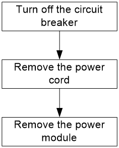
To remove the power module:
1. Turn off the circuit breaker of the power cord.
2. Wear an ESD wrist strap and make sure the strap makes good skin contact and is reliably grounded.
3. Loosen the cable tie, and remove the power cord.
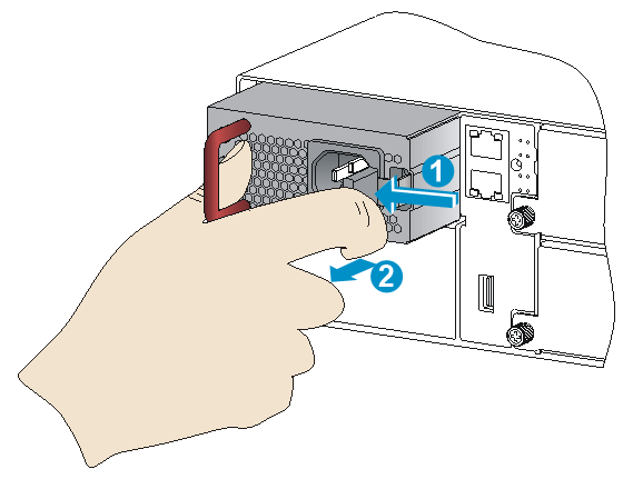
4. As shown in Figure 9, press the latch towards the handle, and pull the power module along the guide rails until it is part-way out.
5. Grasp the handle of the power module with one hand, and hold the bottom of the power module with the other hand to pull the power module slowly along the guide rails out of the slot.
Figure 9 Removing the power module
6. Put the removed power module on an antistatic mat or into its package.
|
|
NOTE: If you do not insert another power module into the slot after removing the power module, install the filler panel to the power module slot to prevent dust from entering the chassis. |