- Table of Contents
- Related Documents
-
| Title | Size | Download |
|---|---|---|
| 02-INT configuration | 122.31 KB |
Contents
Restrictions and guidelines: INT configuration
Display and maintenance commands for INT
Example: Configuring common INT
Example: Configuring flexible INT
Configuring INT
About INT
The Inband Network Telemetry (INT) feature is a network monitoring technology designed to collect data from the device. The device sends data to a collector in real time for device performance monitoring and network monitoring.
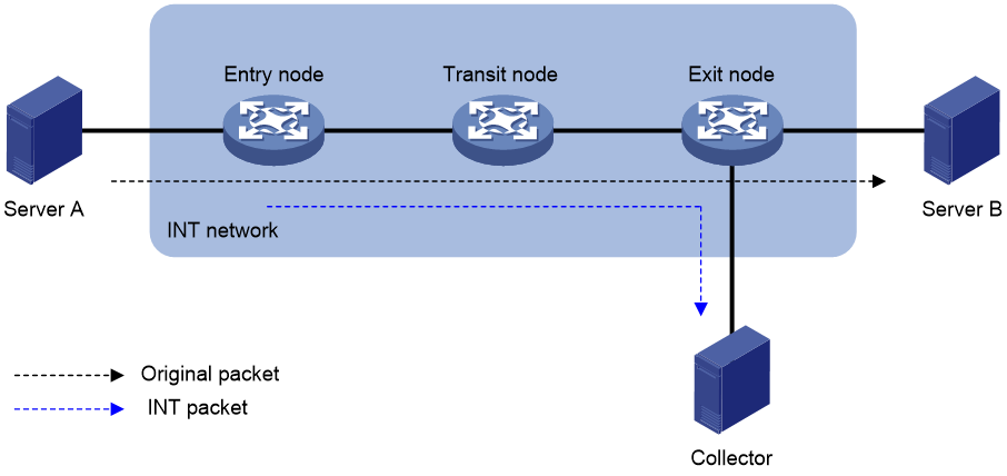
INT network components
As shown in Figure 1, an INT network contains the following INT-enabled devices: one entry node, one transit node, and one exit node.
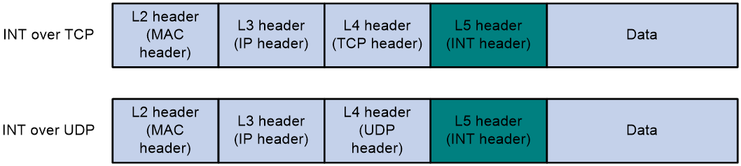
INT packet formats
INT generates INT packets by mirroring original packets, inserting INT headers, and collecting data. The INT header and collected data are in the original IP header. Therefore, an INT packet and its original packet have the same IP header and forwarding path.
The device supports generating INT packets from TCP packets and UDP packets. Figure 2 shows the INT packet formats. The 64 most significant bits of the INT header are fixed at 0xaaaaaaaabbbbbbbb, which are the INT mark.
How INT works
INT supports common INT and flexible INT. The two types of INT have the following differences:
· Common INT—Each node needs to be configured with an INT role on its input interface: ingress, transit, and egress. Traffic flows are defined on the entry node by using a QoS policy. INT flows are automatically identified on the transit node and exit node and processed according to configured actions. On each input interface in the path, you can perform INT processing only on the flows defined on the entry node.
· Flexible INT—No device role needs to be configured on each node. On each node, an ACL can be used to define a flow and an action used to take on the defined flow. For the same flow, the original packets are matched on the entry node, and the INT packets are matched on the transit node and exit node. You can define multiple flows on an interface and take different actions on different flows.
Common INT is easy to configure and is recommended. Use flexible INT only when you need to process multiple flows on an interface.
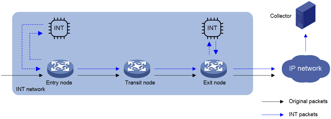
Common INT
As shown in Figure 3, the nodes in common INT perform the following functions:
1. On the entry node, the ingress port uses a QoS policy to sample matching packets, and mirrors sampled packets to the INT processor. Then, the INT processor adds an INT header to the INT packet and loops it back to the ingress port. The ingress port identifies the looped-back INT packet according to the INT mark, adds collected data to it, and forwards it to the egress port. The egress port adds collected data to the INT packet and sends it to the transit node.
2. On the transit node, the ingress port identifies the INT packet according to the INT mark, adds collected data to it, and forwards it to the egress port. The egress port adds collected data to the INT packet, and sends it to the exit node.
3. On the exit node, the ingress port identifies the INT packet according to the INT mark, adds collected data to the INT packet, encapsulates the INT packet with the configured parameters, and sends it to the collector.
Flexible INT
As shown in Figure 3, the nodes in flexible INT perform the following functions:
1. On the entry node, the input interface uses an ACL to sample matching packets, and mirrors sampled packets to the INT processor. Then, the INT processor adds an INT header to the INT packet and loops it back to the input interface. The ingress port identifies the looped-back INT packet according to an ACL and adds collected data to it, and forwards it. The egress port adds collected data to the INT packet and sends it to the transit node.
2. On the transit node, the input interface uses an ACL to identify INT packets, adds collected data to INT packets, and forwards them to the input interface. The input interface adds collected data to INT packets and sends them to the exit node.
3. On the exit node, the input interface uses an ACL to identify INT packets and mirrors them to the INT processor. The INT processor encapsulates the INT packets and sends them to the collector.
Restrictions and guidelines: INT configuration
Common INT and flexible INT can only be deployed in underlay networks.
The switch can act as only transit nodes.
Configuring basic INT
Configuring the transit node
a. Enter system view.
system-view
b. Specify a device ID for the transit node.
telemetry ifa device-id address
By default, the transit node does not have a device ID.
2. Configure the transit interface.
a. Enter interface view.
interface interface-type interface-number
b. Specify the interface as the transit interface.
telemetry ifa role transit
By default, an interface is not used as the transit interface.
c. Return to system view
quit
3. Enable INT globally.
telemetry ifa global enable
By default, INT is enabled globally.
Configuring enhanced INT
1. Specify a device ID.
a. Enter system view.
system-view
b. Specify a device ID for the transit node.
telemetry ifa device-id address
By default, the transit node does not have a device ID.
2. Add collected data to INT packets on the input interface.
a. Create a user-defined ACL and enter user-defined ACL view.
For information about the acl configuration command, see ACL commands in ACL and QoS Command Reference.
b. Configure a rule for the user-defined ACL.
For information about the rule (user-defined ACL view) configuration command, see ACL commands in ACL and QoS Command Reference.
If the entry node uses an ACL when mirroring packets to the INT processor, the ACLs used for any other action on any node must have the same identification attributes plus an attribute to identify the INT flag. The identification attributes and the attribute to identify the INT flag must be in the same rule. For example, the rule in the ACL used on the entry node is rule permit tcp source 10.0.0.3 0, the rule in the ACL used for any other action must be rule permit tcp source 10.0.0.3 0 ifa l5 aaaaaaaabbbbbbbb ffffffffffffffff 0.
c. Return to system view.
quit
d. Enter interface view.
interface interface-type interface-number
e. Configure the action of adding collected data to incoming INT packets.
telemetry ifa ifa-id acl user-defined { acl-number | name acl-name } action add-metadata
By default, no action is configured.
f. Return to system view.
quit
3. Enable INT globally.
telemetry ifa global enable
By default, INT is enabled globally.
Display and maintenance commands for INT
Execute display commands in any view.
|
Task |
Command |
|
Display INT configuration. |
display telemetry ifa |
INT configuration examples
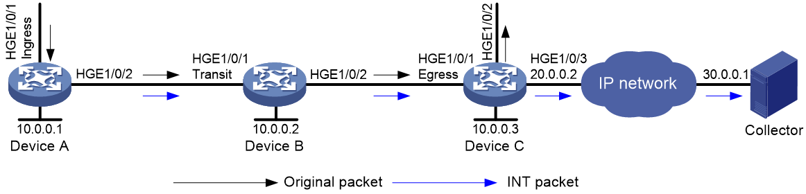
Example: Configuring common INT
Network configuration
As shown in Figure 4, configure common INT to test the link delay.
Procedure
1. Assign IP addresses to interfaces and configure routes. Make sure the network connections are available. (Details not shown.)
2. Configure Device B:
# Specify 10.0.0.2 as the device ID of the transit node.
<DeviceB> system-view
[DeviceB] telemetry ifa device-id 10.0.0.2
# Specify HundredGigE 1/0/1 as the transit interface.
[DeviceB] interface hundredgige 1/0/1
[DeviceB-HundredGigE1/0/1] telemetry ifa role transit
[DeviceB-HundredGigE1/0/1] quit
# Enable INT globally.
[DeviceB] telemetry ifa global enable
Verify the configuration
# Verify the configuration on Device B.
[DeviceB] display telemetry ifa
Telemetry ifa status: Enabled
Telemetry ifa device-id: 10.0.0.2
Telemetry ifa role:
HundredGigE1/0/1: Transit
Example: Configuring flexible INT
Network configuration
As shown in Figure 5, configure flexible INT to test the link delay. Device C sends INT packets with entry node metadata and transit node metadata to the collector while sending both INT packets with exit node metadata and original packets to the IP network. The user network sends the INT packets with exit node metadata to the collector.

Procedure
1. Assign IP addresses to interfaces and configure routes. Make sure the network connections are available. (Details not shown.)
2. Configure Device B:
# Specify 10.0.0.2 as the device ID of the transit node.
<DeviceB> system-view
[DeviceB] telemetry ifa device-id 10.0.0.2
# Create user-defined ACL 5000, and configure a rule to match INT packets with source IP address 192.168.1.2.
[DeviceB] acl user-defined 5000
[DeviceB-acl-user-5000] rule permit tcp source 192.168.1.2 0 ifa l5 aaaaaaaabbbbbbbb ffffffffffffffff 0
[DeviceB-acl-user-5000] rule permit udp source 192.168.1.2 0 ifa l5 aaaaaaaabbbbbbbb ffffffffffffffff 0
[DeviceB-acl-user-5000] quit
# Add collected metadata to incoming INT packets on HundredGigE 1/0/1.
[DeviceB] interface hundredgige 1/0/1
[DeviceB-HundredGigE1/0/1] telemetry ifa 1 acl user-defined 5000 action add-metadata
[DeviceB-HundredGigE1/0/1] quit
# Enable INT globally.
[DeviceB] telemetry ifa global enable
Verify the configuration
# Verify the configuration on Device B.
[DeviceB] display telemetry ifa
Telemetry ifa status: Enabled
Telemetry ifa device-id: 10.0.0.2
Telemetry ifa action:
HundredGigE1/0/1:
Telemetry ifa 1 acl user-defined 5000 action add-metadata