- Table of Contents
- Related Documents
-
| Title | Size | Download |
|---|---|---|
| 01-Text | 5.85 MB |
Examining the installation site
Installing the switch in a 19-inch rack
Mounting brackets, chassis rails, and grounding cable installation positions
Rack-mounting procedures at a glance
Attaching the mounting brackets and chassis rails to the chassis
Connecting the grounding cable to the chassis
Attaching the slide rails to the rack
Mounting the switch in the rack
Installing/removing power modules
Installing/removing expansion cards
Accessing the switch for the first time
Setting up the configuration environment
Connecting the mini USB console cable
Planning IRF fabric size and the installation site
Identifying the master switch and planning IRF member IDs
Planning IRF topology and connections
Identifying physical IRF ports on the member switches
Configuring basic IRF settings
Connecting the physical IRF ports
Accessing the IRF fabric to verify the configuration
Maintenance and troubleshooting
Configuration terminal display problems
Appendix A Chassis views and technical specifications
Preparing for installation
The H3C S6820 Switch Series includes the following models:
· S6820-32H.
· S6820-56HF.
· S6820-4C.
Safety recommendations
To avoid any equipment damage or bodily injury caused by incorrect use, read the following safety recommendations before installation. Note that the recommendations do not cover every possible hazardous condition.
· Before cleaning the switch, remove all power cords from the switch. Do not clean the switch with wet cloth or liquid.
· Do not place the switch near water or in a damp environment. Prevent water or moisture from entering the switch chassis.
· Do not place the switch on an unstable case or desk. The switch might be severely damaged in case of a fall.
· Ensure good ventilation of the equipment room and keep the air inlet and outlet vents of the switch free of obstruction.
· Connect the yellow-green protection grounding cable before power-on.
· Make sure the operating voltage is in the required range.
· To avoid electrical shocks, do not open the chassis while the switch is operating or when the switch is just powered off.
· When replacing field replaceable units (FRUs), including power modules and fan trays, wear an ESD wrist strap to avoid damaging the units.
Examining the installation site
The switch must be used indoors.
Mount your switch in a rack and verify the following items:
· Adequate clearance is reserved at the air inlet and outlet vents for ventilation.
· The rack has a good ventilation system.
· Identify the hot aisle and cold aisle at the installation site, and make sure ambient air flows into the switch from the cold aisle and exhausts to the hot aisle.
· Identify the airflow designs of neighboring devices, and prevent hot air flowing out of the neighboring devices from entering the top device.
· The rack is sturdy enough to support the switch and its accessories.
· The rack is reliably grounded.
To ensure correct operation and long service life of your switch, install it in an environment that meets the requirements described in the following subsections.
Temperature/humidity
Maintain appropriate temperature and humidity in the equipment room.
· Lasting high relative humidity can cause poor insulation, electricity leakage, mechanical property change of materials, and metal corrosion.
· Lasting low relative humidity can cause washer contraction and ESD and cause problems including loose mounting screws and circuit failure.
· High temperature can accelerate the aging of insulation materials and significantly lower the reliability and lifespan of the switch.
For the temperature and humidity requirements for the switch, see "Technical specifications."
Cleanliness
Dust buildup on the chassis might result in electrostatic adsorption, which causes poor contact of metal components and contact points, especially when indoor relative humidity is low. In the worst case, electrostatic adsorption can cause communication failure.
Table 1 Dust concentration limit in the equipment room
|
Substance |
Concentration limit (particles/m³) |
|
Dust |
≤ 3 × 10⁴ (no visible dust on the tabletop over three days) |
|
NOTE: Dust diameter ≥ 5 μm |
|
The equipment room must also meet limits on salts, acids, and sulfides to eliminate corrosion and premature aging of components, as shown in Table 2.
Table 2 Harmful gas limits in the equipment room
|
Gas |
Maximum concentration (mg/m3) |
|
SO2 |
0.2 |
|
H2S |
0.006 |
|
NH3 |
0.05 |
|
Cl2 |
0.01 |
EMI
All electromagnetic interference (EMI) sources, from outside or inside of the switch and application system, adversely affect the switch in the following ways:
· A conduction pattern of capacitance coupling.
· Inductance coupling.
· Electromagnetic wave radiation.
· Common impedance (including the grounding system) coupling.
To prevent EMI, use the following guidelines:
· If AC power is used, use a single-phase three-wire power receptacle with protection earth (PE) to filter interference from the power grid.
· Keep the switch far away from radio transmitting stations, radar stations, and high-frequency devices.
· Use electromagnetic shielding, for example, shielded interface cables, when necessary.
· To prevent signal ports from getting damaged by overvoltage or overcurrent caused by lightning strikes, route interface cables only indoors.
Laser safety
|
|
WARNING! · The switch is a Class 1M laser device. · Disconnected optical fibers or transceiver modules might emit invisible laser light. Do not stare into beams or view directly with optical instruments when the switch is operating. |
Installation tools
No installation tools are provided with the switch. Prepare the following tools yourself:
· Phillips screwdriver.
· ESD wrist strap.
· Marker.
Installing the switch
|
|
CAUTION: Keep the tamper-proof seal on a mounting screw on the chassis cover intact, and if you want to open the chassis, contact H3C for permission. Otherwise, H3C shall not be liable for any consequence caused thereby. |
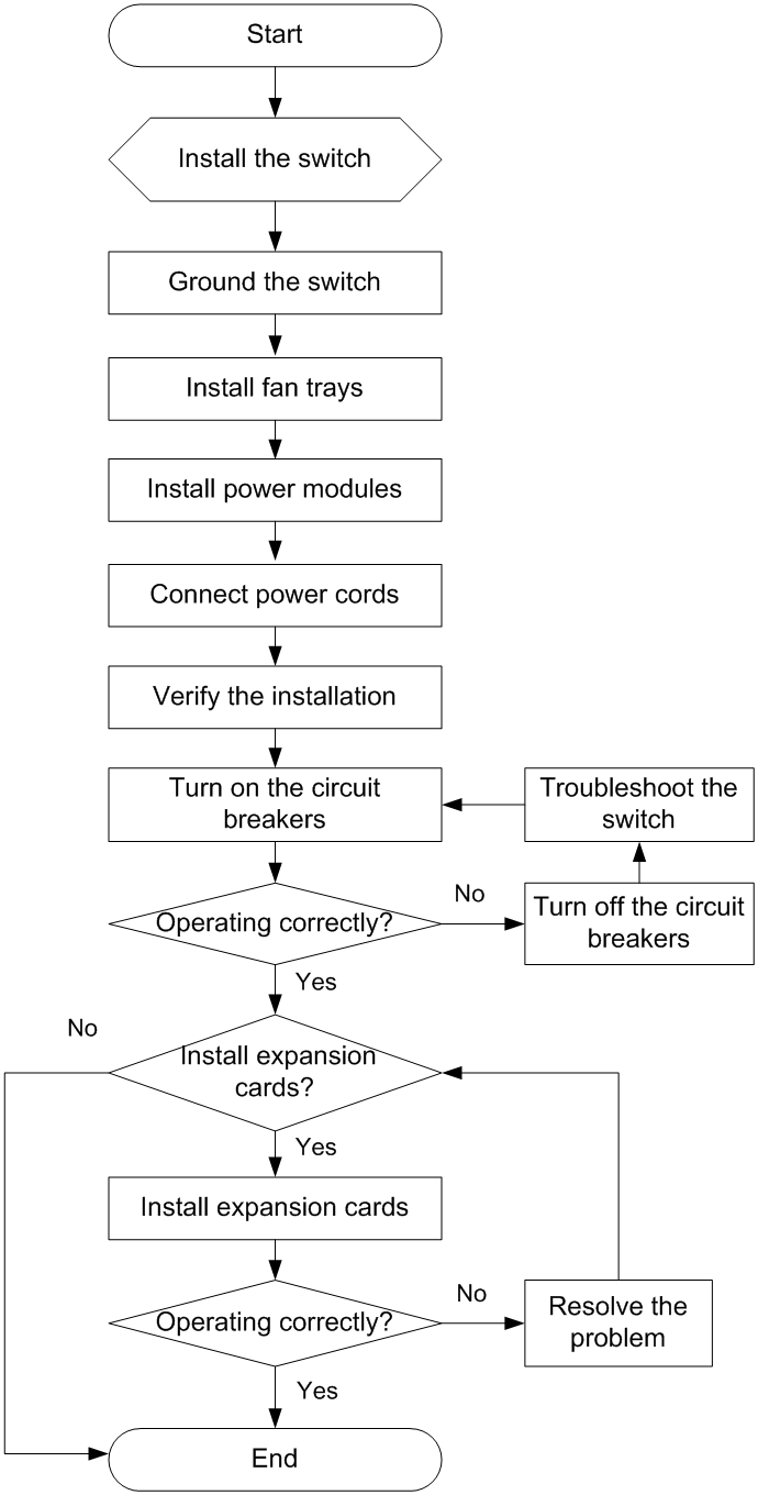
Figure 1 Hardware installation flow
Installing the switch in a 19-inch rack
|
IMPORTANT: To install the switch in a 19-inch rack, make sure the rack has a minimum depth of 1000 mm (39.37 in) so that the rack door can be closed easily. |
Installation accessories
Table 3 Installation accessories
|
Switch model |
Mounting brackets (provided) |
Cable management brackets |
Rack mounting rail kit |
|
S6820-32H |
1U high, one pair. See Figure 2. |
N/A |
· 1U high, including one pair of long slide rails and one pair of chassis rails (provided). See Figure 7. · 1U high, including one pair of short slide rails and one pair of chassis rails (optional). See Figure 6. |
|
S6820-56HF |
1U high, one pair. See Figure 3. |
N/A |
· 1U high, including one pair of long slide rails and one pair of chassis rails (provided). See Figure 7. · 1U high, including one pair of super-short slide rails and one pair of chassis rails (optional). See Figure 5. |
|
S6820-4C |
2U high, one pair. See Figure 4. |
One pair (provided). See Figure 4. |
· 2U high, including one pair of slide rails and one pair of chassis rails (provided). See Figure 8. |
Figure 2 Mounting brackets provided with the S6820-32H switch
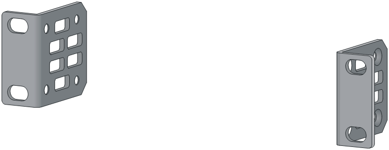
Figure 3 Mounting brackets provided with the S6820-56HF switch
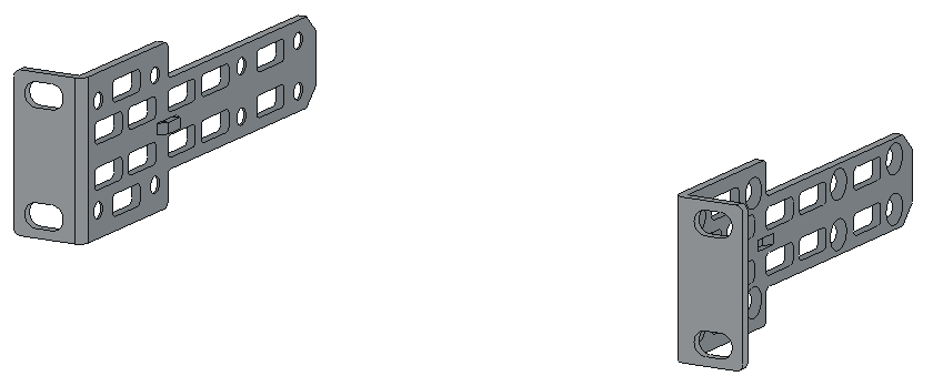
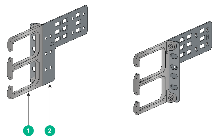
Figure 4 Mounting brackets provided with the S6820-4C switch
|
(1) Cable management bracket |
(2) Mounting bracket |
Figure 5 1U super-short slide rail and chassis rail
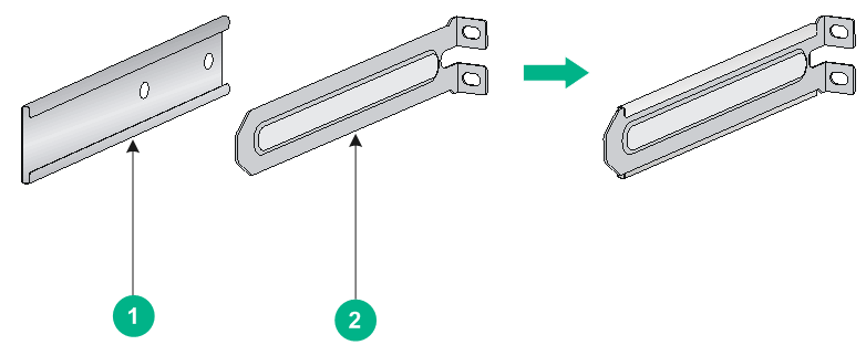
|
(1) Chassis rail |
(2) Super-short slide rail |
Figure 6 1U short slide rail and chassis rail
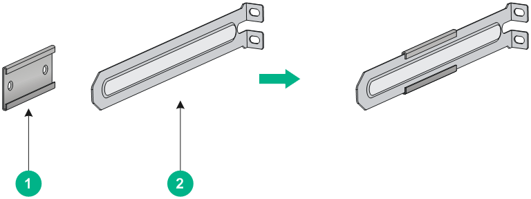
|
(1) Chassis rail |
(2) Short slide rail |
Figure 7 1U long slide rail and chassis rail
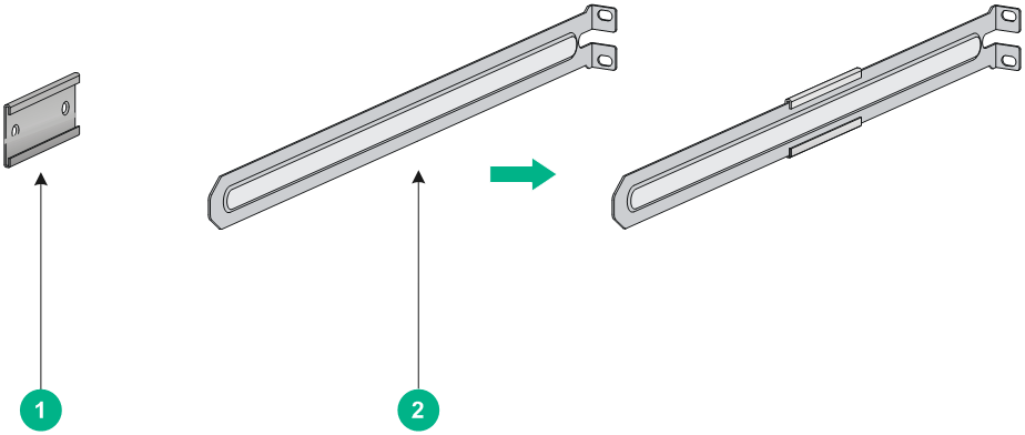
|
(1) Chassis rail |
(2) Long slide rail |
Figure 8 2U slide rail and chassis rail
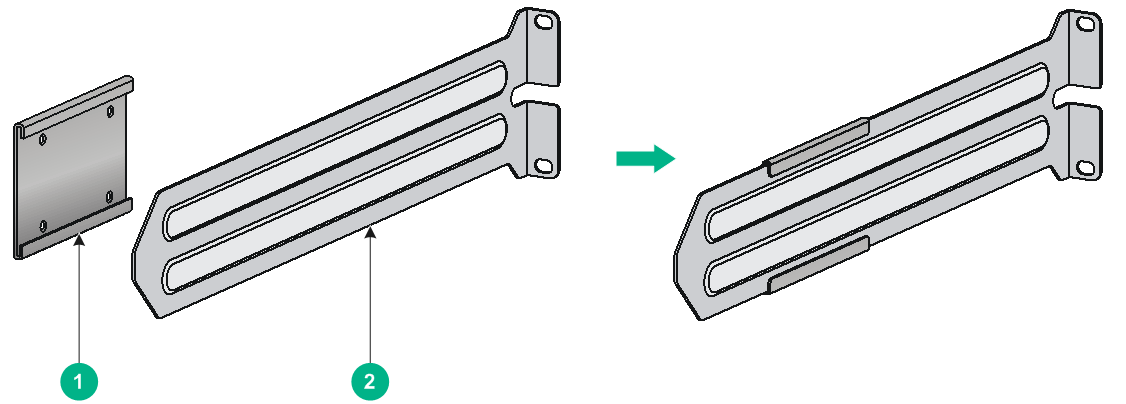
|
(1) Chassis rail |
(2) Slide rail |
Mounting brackets, chassis rails, and grounding cable installation positions
The switch has one mounting position near the network ports and one mounting position near the power modules for mounting brackets.
The S6820-4C switch provides three grounding points: primary grounding point (with a grounding sign), auxiliary grounding point 1, and auxiliary grounding point 2. The S6820-32H and S6820-56HF switches provide two grounding points: primary grounding point (with a grounding sign) and auxiliary grounding point. See Figure 9, Figure 10, and Figure 11.
Select installation positions for the mounting brackets, chassis rails, and grounding cable as required.
Figure 9 Mounting brackets and grounding cable installation positions on the S6820-32H switch
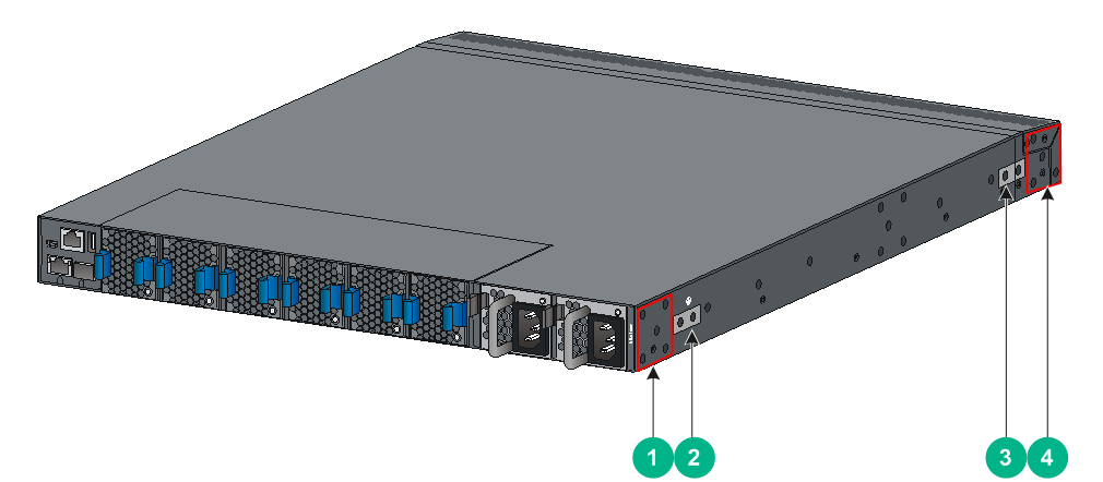
|
(1) Power module-side mounting position |
(2) Primary grounding point |
|
(3) Auxiliary grounding point |
(4) Port-side mounting position |
Figure 10 Mounting brackets and grounding cable installation positions on the S6820-56HF switch
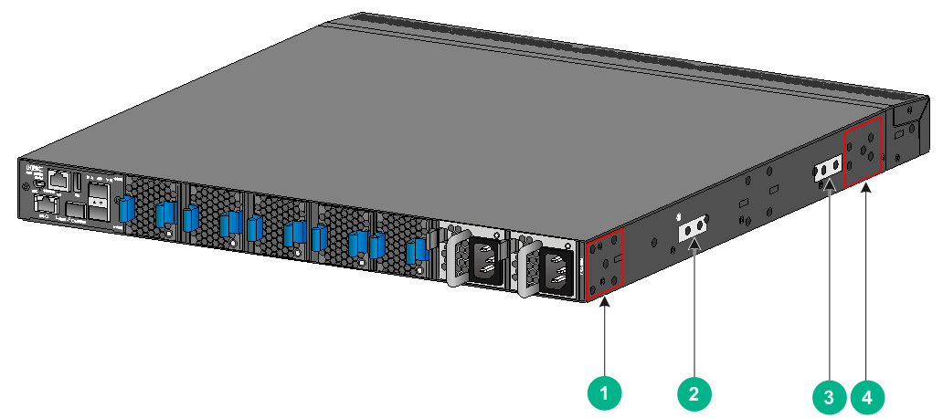
|
(1) Power module-side mounting position |
(2) Primary grounding point |
|
(3) Auxiliary grounding point |
(4) Port-side mounting position |
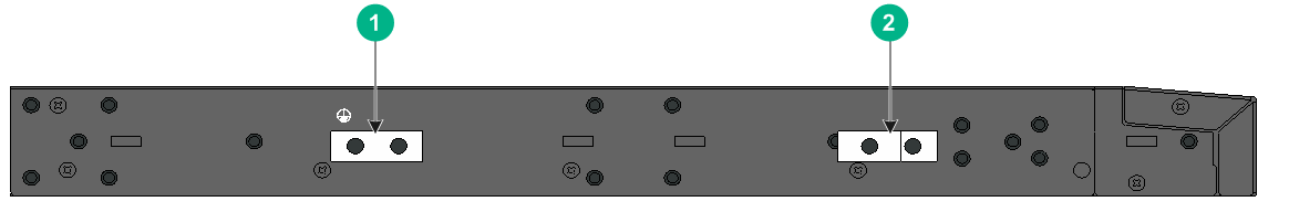
Figure 11 Mounting brackets and grounding cable installation positions on the S6820-4C switch
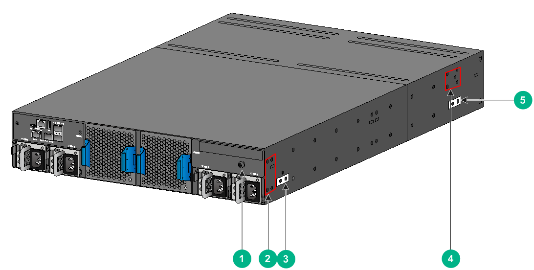
|
(1) Auxiliary grounding point 2 |
(2) Power module-side mounting position |
|
(3) Primary grounding point |
(4) Port-side mounting position |
|
(5) Auxiliary grounding point 1 |
|
Rack-mounting procedures at a glance
Figure 12 Rack-mounting procedure

|
|
NOTE: If a rack shelf is available, you can put the switch on the rack shelf, slide the switch to an appropriate location, and attach the switch to the rack with the mounting brackets. |
Follow these guidelines when you install the switch in a 19-inch rack:
· The distance between the front and rear posts of the rack must meet the requirements described in Table 4.
· To secure the switch to the rack, you must install not only mounting brackets, but also chassis rails and slide rails.
Table 4 Distance requirements between the front and rear rack posts
|
Switch model |
Installation method |
Minimum distance between the front and rear rack posts |
Maximum distance between the front and rear rack posts |
|
S6820-32H |
Using the mounting brackets and long slide rails (provided) |
621 mm (24.45 in) |
934 mm (36.77 in) |
|
Using the mounting brackets and short slide rails (optional) |
401 mm (15.79 in) |
714 mm (28.11 in) |
|
|
S6820-56HF |
Using the mounting brackets and long slide rails (provided) |
692 mm (27.24 in) |
854 mm (33.62 in) |
|
Using the mounting brackets and super-short slide rails (optional, with the chassis rails not reaching out of the chassis) |
401 mm (15.79 in) |
565 mm (22.24 in) |
|
|
Using the mounting brackets and super-short slide rails (optional, with chassis rails reaching out of the chassis) |
499 mm (19.65 in) |
692 mm (27.24 in) |
|
|
S6820-4C |
Using the mounting brackets and slide rails (provided) |
518 mm (20.40 in) |
858 mm (33.78 in) |
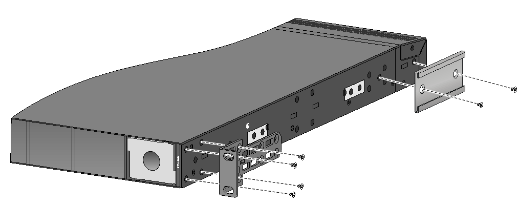
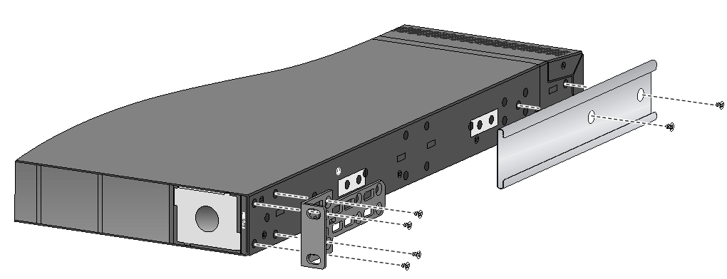
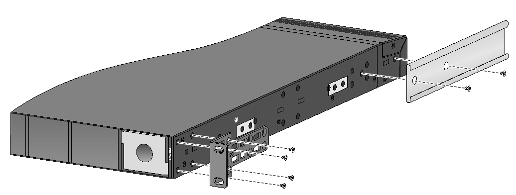
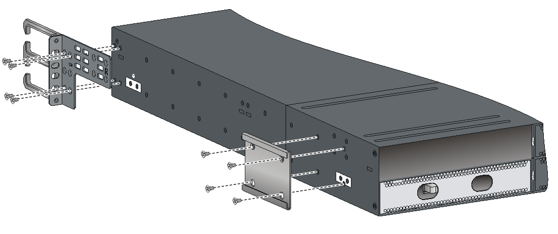
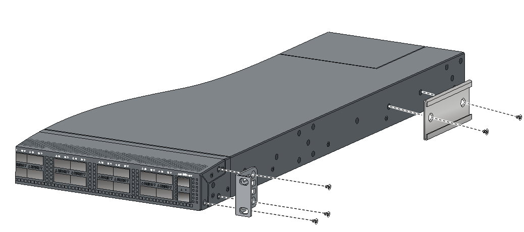
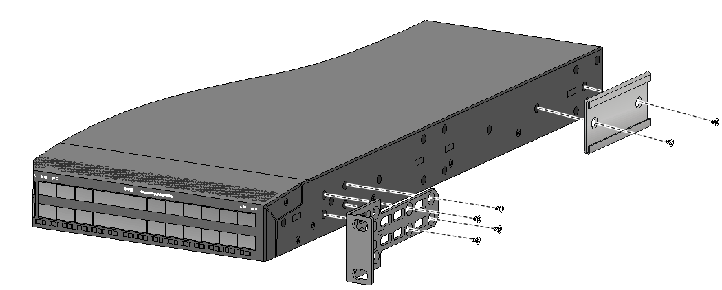
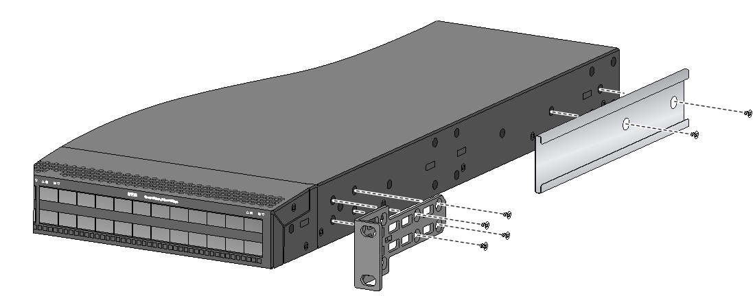
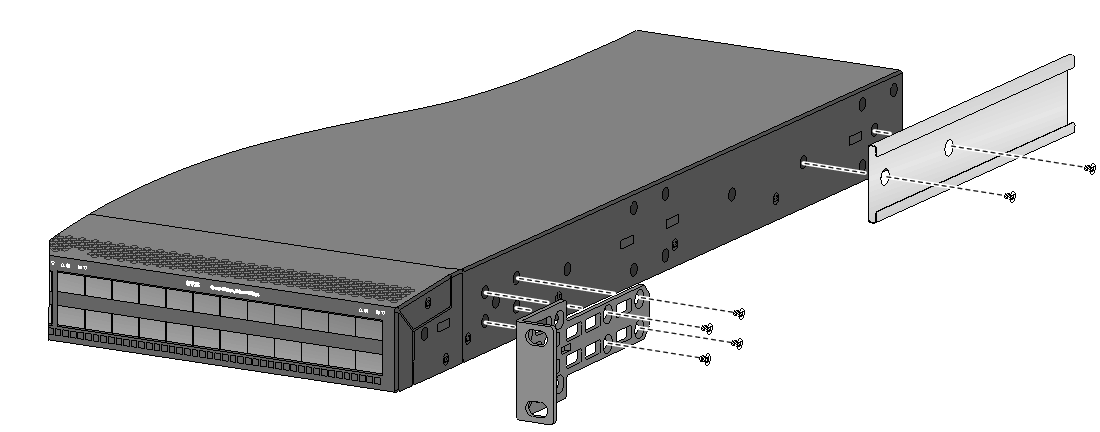
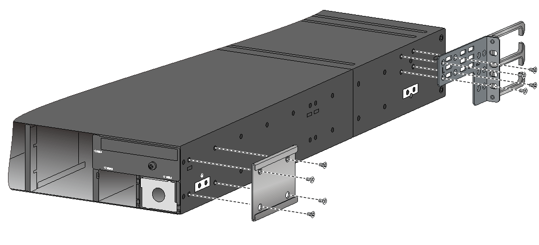
Attaching the mounting brackets and chassis rails to the chassis
1. Place the wide flange of the mounting bracket against the chassis side panel. Align the mounting bracket installation holes with the screw holes in the chassis. Use M4 screws (provided) to attach the mounting bracket to the chassis.
¡ To install the mounting brackets at the power module-side mounting position, see Figure 13, Figure 14, Figure 15, Figure 16, and Figure 17.
¡ To install the mounting brackets at the port-side mounting position, see Figure 18, Figure 19, Figure 20, Figure 21, and Figure 22.
For the S6820-56HF and S6820-4C switches, to install the mounting brackets at the power module-side mounting position, use the four screw holes nearest to the power module side. To install the mounting brackets at the network port-side mounting position, use the four screw holes nearest to the network port side.
2. Determine the chassis rail installation position:
¡ If the mounting brackets are installed at the power module-side mounting position, install the chassis rails near the port side.
¡ If the mounting brackets are installed at the network port-side mounting position, install the chassis rails near the power module side.
3. Place the chassis rail against the chassis side panel. Align the chassis rail installation holes with the screw holes. Use M4 screws (provided) to attach the chassis rail to the chassis. See Figure 13 to Figure 22.
You can use super-short slide rails and long chassis rails to rack-mount the S6820-56HF switch. Based on the rack depth, install the long chassis rails not reaching out of the chassis, as shown in Figure 15 and Figure 20 or reaching out of the chassis, as shown in Figure 16 and Figure 21.
Figure 13 Attaching the mounting brackets and chassis rails to the S6820-32H switch (power module-side mounting position for the mounting brackets)
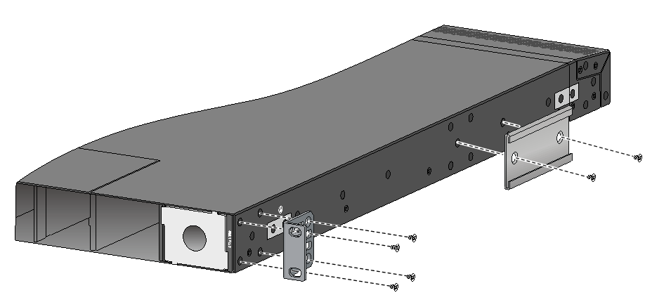
|
|
NOTE: Secure the mounting brackets and chassis rails to both sides of the chassis in the same way. |
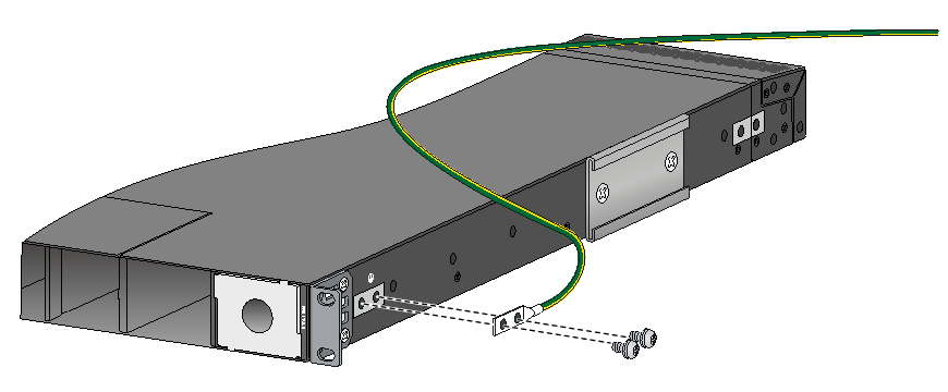
Connecting the grounding cable to the chassis
|
|
CAUTION: The primary grounding point and auxiliary grounding point 1 are located on the left panel of the chassis. If you use one of these grounding points, you must connect the grounding cable to the grounding point before you mount the switch in the rack. |
As a best practice, use the primary grounding point or auxiliary grounding point 1 because the grounding cable and grounding screw that come with the switch are suitable only for these two grounding points.
To use auxiliary grounding point 2 on the S6820-4C switch, prepare a grounding cable yourself.
This section uses the primary grounding point on the S6820-32H switch as an example.
To connect the grounding cable to a grounding point:
1. Choose a grounding point as required.
This example uses the primary grounding point.
2. Unpack the grounding cable and grounding screws.
3. Use two grounding screws to attach the two-hole grounding lug of the grounding cable to the grounding holes at the grounding point. Use a screwdriver to tighten the screws. See Figure 23.
Figure 23 Attaching the grounding cable to the primary grounding point on the S6820-32H switch
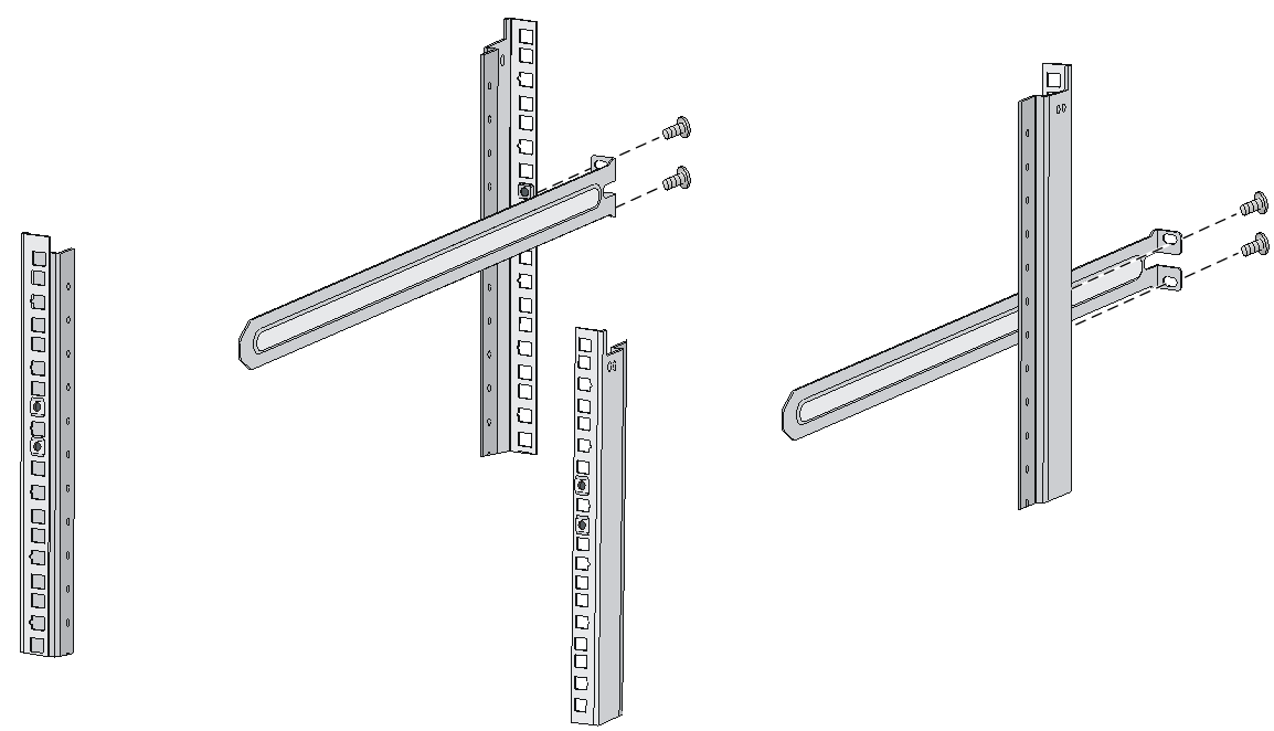
Attaching the slide rails to the rack
The procedure is the same for attaching 1U and 2U slide rails to the rack. This section uses the 1U slide rails as an example.
To attach the slide rails to the rack:
1. Identify the slide rail installation position in the rack.
2. Install cage nuts (user-supplied) in the mounting holes in the rack posts.
3. Align the screw holes in one slide rail with the cage nuts in a rear rack post, and use screws (user-supplied) to attach the slide rail to the post, as shown in Figure 24.
4. Repeat the preceding steps to attach the other slide rail to the other rear rack post.
Keep the two slide rails at the same height so the slide rails can attach into the chassis rails.
Figure 24 Installing the 1U slide rails
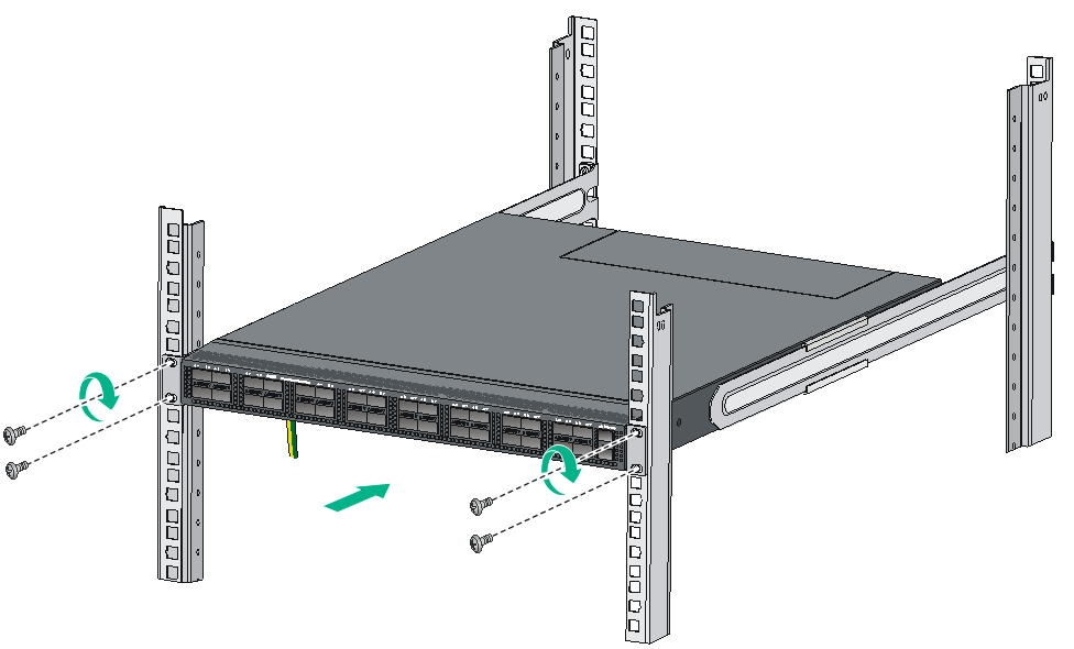
Mounting the switch in the rack
This task requires two people.
To mount the switch in the rack:
1. Wear an ESD wrist strap and make sure it makes good skin contact and is reliably grounded.
2. Verify that the mounting brackets and chassis rails have been securely attached to the switch chassis.
3. Verify that the slide rails have been correctly attached to the rear rack posts.
4. Attach cage nuts (user-supplied) to the front rack posts and make sure they are at the same level as the slide rails.
5. One person performs the following operations:
a. Supporting the bottom of the switch, aligns the chassis rails with the slide rails on the rack posts.
b. Pushes the switch slowly to slide the chassis rails along the slide rails until the mounting brackets are flush with the rack posts.
6. Another person uses screws (user-supplied) to attach the mounting brackets to the rack.
To secure the switch in the rack, make sure the front ends of the slide rails reach out of the chassis rails.
The rack-mounting procedures are the same for the S6820-56HF and S6820-32H switches. The following figures use the S6820-32H switch as an example.
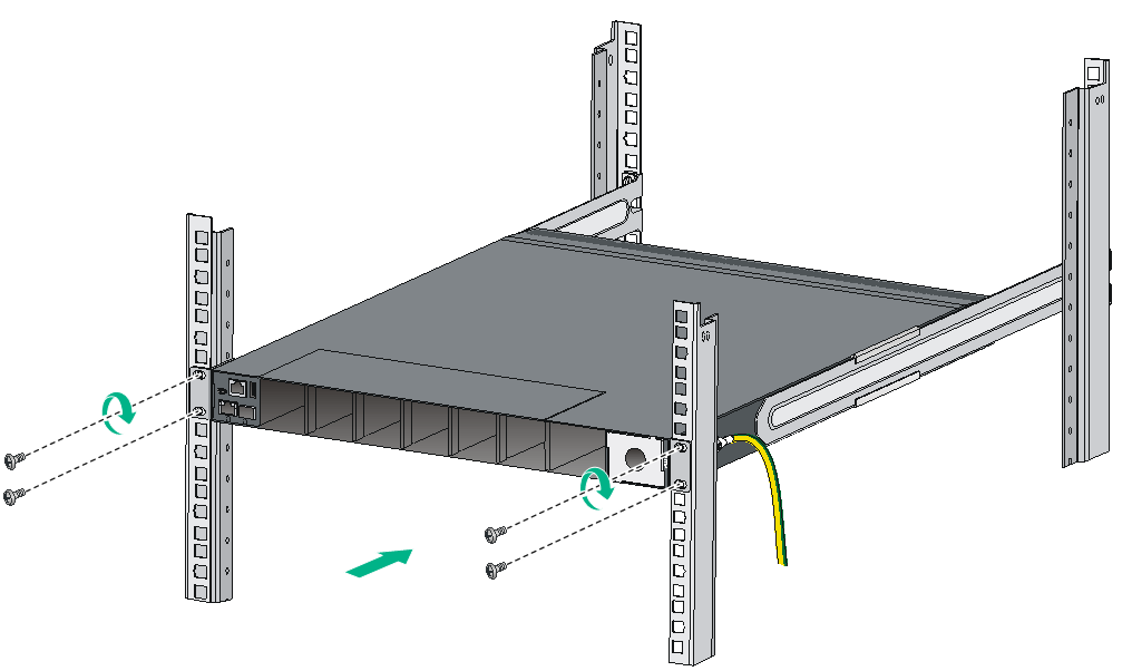
Figure 26 Mounting the S6820-32H switch in the rack (Port-side mounting position for the mounting brackets)
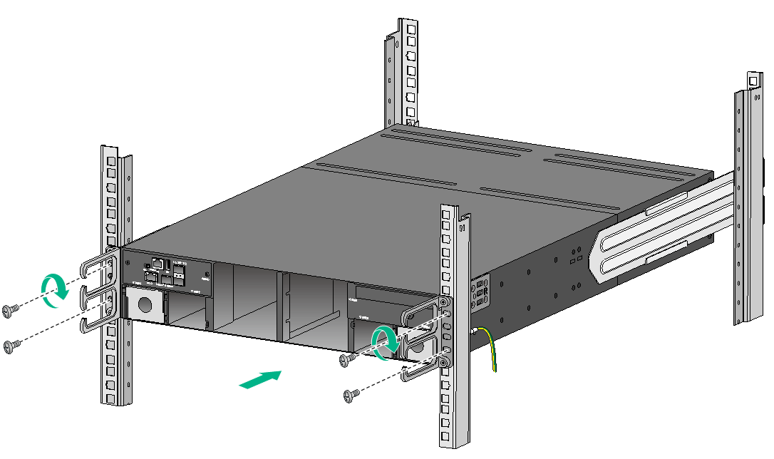
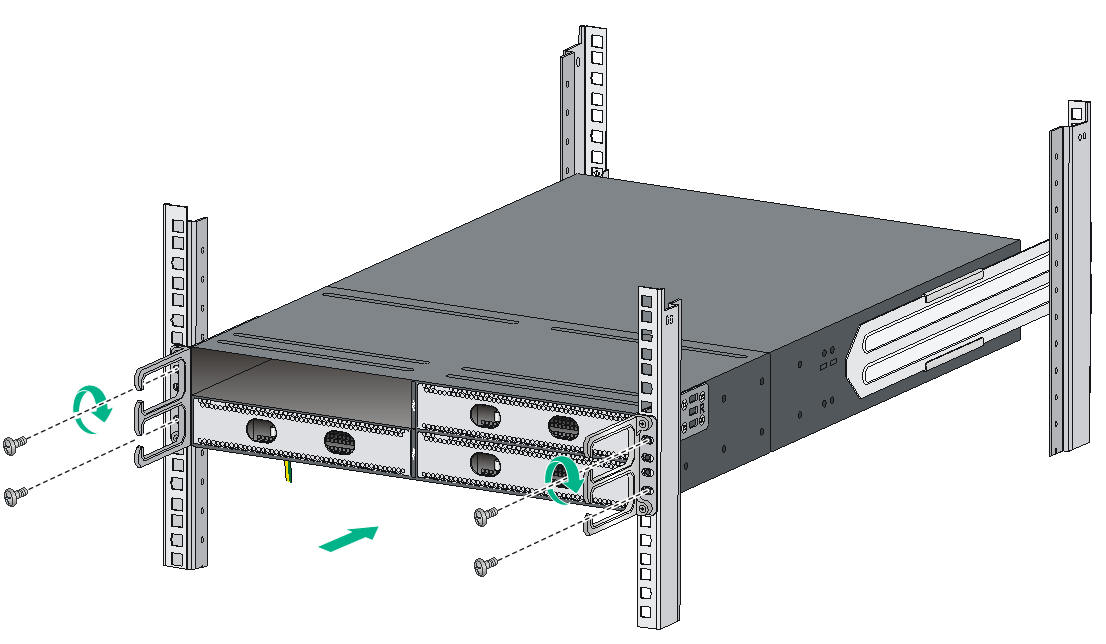
|
|
NOTE: To rack-mount the S6820-4C switch by using 2U high mounting brackets and slide rails, use two screws and two cage nuts to attach each mounting bracket to the rack. Determine the screw installation positions based on the distances between the square holes on the rack posts. The screw installation positions in Figure 27 and Figure 28 are for illustration only. |
Grounding the switch
|
|
CAUTION: · Correctly connecting the grounding cable is crucial to lightning protection and EMI protection. · Do not connect the grounding cable to a fire main or lightning rod. · To guarantee the grounding effect and avoid switch damage, use the grounding cable provided with the switch to connect the switch to a grounding strip in the equipment room. |
The power input end of the switch has a noise filter, whose central ground is directly connected to the chassis to form the chassis ground (commonly known as PGND). You must securely connect this chassis ground to the earth so the faradism and leakage electricity can be safely released to the earth to minimize EMI susceptibility of the switch.
To ground the switch:
1. As shown in Figure 29, attach the two-hole grounding lug of the grounding cable to a grounding point on the chassis. For more information, see "Connecting the grounding cable to the chassis."
The grounding point in Figure 29 is for illustration only.
2. Remove the hex nut of a grounding post on the grounding strip.
3. Attach the ring terminal of the grounding cable to the grounding post on the grounding strip, and secure the ring terminal to the grounding post with the hex nut.
Figure 29 Connecting the grounding cable to a grounding strip
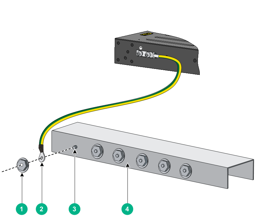
|
(1) Hex nut |
(2) Ring terminal |
|
(3) Grounding post |
(4) Grounding strip |
Installing/removing fan trays
|
|
CAUTION: The switch has multiple fan tray slots. To ensure good ventilation of the switch, follow these guidelines to install and remove fan trays: · The switch is provided with the fan tray slots empty. Before powering on the switch, make sure all fan tray slots have fan trays installed and the fan trays are the same model. · Make sure all slots have a module or filler panel installed when the switch is operating. · If multiple fan trays fail on an operating S6820-32H or S6820-56HF switch, do not remove the fan trays at the same time. Replace the fan trays one after another and finish replacing a fan tray within 3 minutes. · If a fan tray fails on an operating S6820-4C switch, replace the fan tray immediately and keep the failed fan tray in position before replacement. If two fan trays fail, finish replacing the fan trays within 1 minute. |
The installation and removal procedures are the same for the LSWM1FANSA, LSWM1FANSAB, LSWM1BFANSC, and LSWM1BFANSCB fan trays. The following installation and removal procedures use the LSWM1FANSA fan tray as an example.
Installing a fan tray
|
|
CAUTION: To prevent damage to the fan tray or the connectors on the backplane, insert the fan tray gently. If you encounter a hard resistance while inserting the fan tray, pull out the fan tray and insert it again. |
|
|
IMPORTANT: Before powering on the switch, make sure the fan tray airflow direction and the preferred airflow direction of the switch are the same. If they are not the same, the system generates traps and logs. You can use the fan prefer-direction command to configure the preferred airflow direction for the switch. By default, the preferred airflow direction of the switch is from the port side to the power module side. For more information about the fan prefer-direction command, see H3C S6820 Switch Series Fundamentals Command Reference. |
Select fan trays for the switch as needed. For the available fan trays and their specifications, see "Fan trays."
To install a fan tray:
1. Wear an ESD wrist strap and make sure it makes good skin contact and is reliably grounded.
2. Unpack the fan tray and verify that the fan tray model is correct.
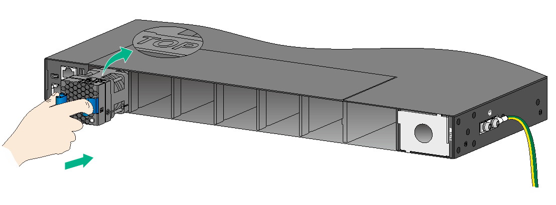
3. Orient the fan tray with the "TOP" mark on top. Grasp the handle of the fan tray with one hand and support the fan tray bottom with the other, and slide the fan tray along the guide rails into the slot until the fan tray is fully seated in the slot and has a firm contact with the backplane. See Figure 30.
Figure 30 Installing an LSWM1FANSA fan tray in the S6820-32H switch
Removing a fan tray
|
|
WARNING! · Ensure electricity safety and never touch the rotating fans when you hot-swap a fan tray. · To prevent a fan from causing loud noise, do not touch the fan blades and rotation axis, even if the fan is not rotating. |
To remove a fan tray:
1. Wear an ESD wrist strap and make sure it makes good skin contact and is reliably grounded.
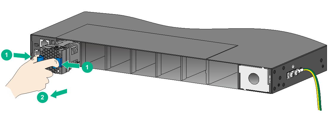
2. Grasp the handle of the fan tray with one hand and pull the fan tray part way out of the slot. Support the fan tray bottom with the other and pull the fan tray completely out of the slot.
3. Put the removed fan tray in an antistatic bag.
Figure 31 Removing an LSWM1FANSA fan tray
Installing/removing power modules
|
|
WARNING! · To avoid bodily injury and device damage, strictly follow the procedures in Figure 32 and Figure 33 to install and remove a power module. · Provide a separate circuit breaker for each power module. |
The S6820-32H and S6820-56HF switches each have two power module slots. The S6820-4C switch has four power module slots. The S6820-32H and S6820-56HF switches come with one power module slot empty and one installed with a filler panel. The S6820-4C switch comes with two power module slots empty and two installed with filler panels. You can install power modules for the switch as required.
For information about the available power modules, see "Appendix B FRUs."
Figure 32 Installation procedure
![]()
![]()
Installing a power module
|
CAUTION: · Follow the forward inertia of the power module when inserting it into the chassis, and make sure the power module has firm contact with the connectors on the backplane. · To prevent damage to the connectors inside the switch chassis, insert the power module gently. If you encounter a hard resistance while inserting the power module, pull out the power module and insert it again. |
The LSVM1AC650 and LSVM1DC650 installation procedure is the same on the S6820 switches. The figures in this section use the S6820-32H switch as an example.
To install a power module:
1. Wear an ESD wrist strap and make sure it makes good skin contact and is reliably grounded.
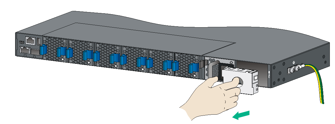
2. Remove the filler panel, if any, from the target power module slot, as shown in Figure 34.
Figure 34 Removing a filler panel
3. Unpack the power module and verify that the power module model is correct.
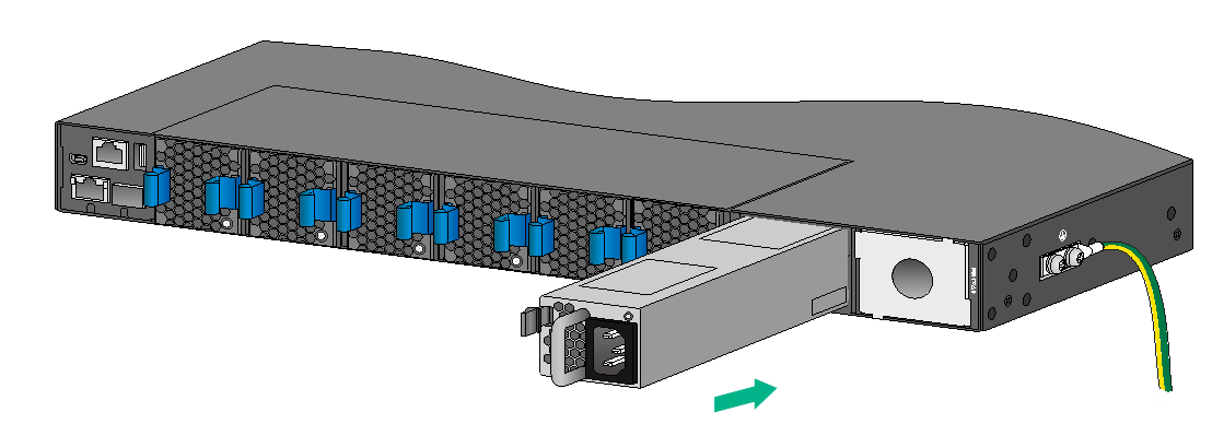
4. Correctly orient the power module with the words on the power module upward. Grasp the handle of the power module with one hand and support its bottom with the other, and slide the power module slowly along the guide rails into the slot.
The slot is foolproof. If you cannot insert the power module into the slot, re-orient the power module rather than use excessive force to push it in.
Figure 35 Installing a power module (LSVM1AC650)
Removing a power module
|
|
CAUTION: · When an S6820-32H or S6820-56HF switch has two power modules in 1+1 redundancy mode, removing one power module does not affect the operation of the switch. When the switch has only one power module installed, removing the power module powers off the switch. · When an S6820-4C switch has power modules in 2+1 or 2+2 redundancy mode, removing one or two power modules does not affect the operation of the switch. When the switch has only two power modules installed, removing power modules powers off the switch or causes power insufficiency. |
The LSVM1AC650 and LSVM1DC650 removal procedure is the same on the S6820 switches. The figures in this section use the S6820-32H switch as an example.
To remove a power module:
1. Wear an ESD wrist strap and make sure it makes good skin contact and is reliably grounded.
2. Squeeze the tabs on the power cord connector with your thumb and forefinger, and pull the connector out to remove the power cord, as shown in Figure 36.
3. Hold the handle on the power module with one hand, pivot the latch on the power module to the right with your thumb, and pull the power module part way out of the slot, as shown in Figure 37.
4. Supporting the power module bottom with one hand, slowly pull the power module out with the other hand.
5. Put the removed power module in an antistatic bag for future use.
6. If you are not to install a new power module, install a filler panel in the slot to ensure good ventilation in the switch.
Figure 36 Removing the DC power cord
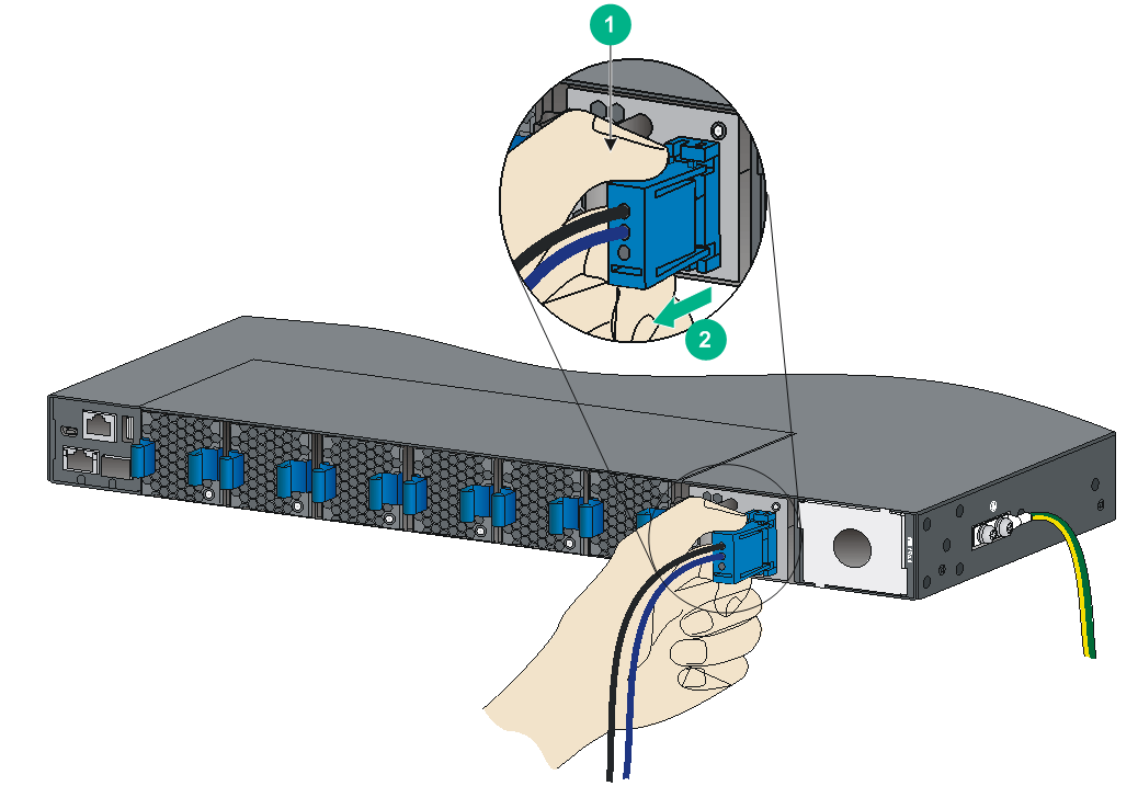
|
(1) Press the tabs on the power cord connector with your thumb and forefinger |
|
(2) Pull the power cord connector out |
Figure 37 Removing the power module
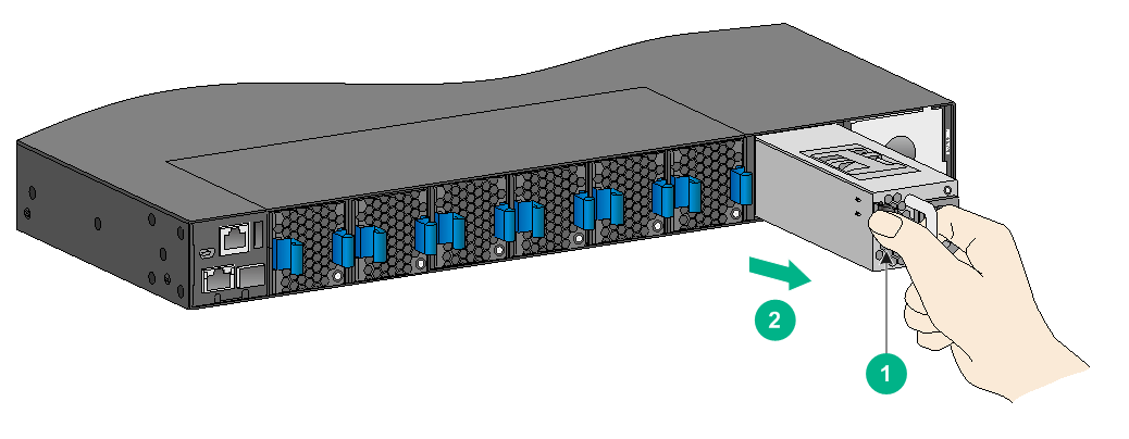
|
(1) Pivot the latch to the right with your thumb |
(2) Pull the power module out |
Connecting the power cords
|
|
WARNING! Provide a circuit breaker for each power input. When you connect a power cord, make sure the circuit breaker is switched off. |
Connecting an AC power cord
1. Insert the female connector of the AC power cord supplied with the power module into the power receptacle on the power module.
2. Use a cable tie to secure the power cord to the handle of the power module, as shown in Figure 38.
3. Connect the other end of the power cord to an AC power outlet.
Figure 38 Connecting an AC power cord to the LSVM1AC650 power module
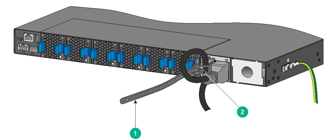
|
(1) Cable tie |
|
(2) Tighten the cable tie to secure the power cord to the handle of the power module |
Connecting a DC power cord
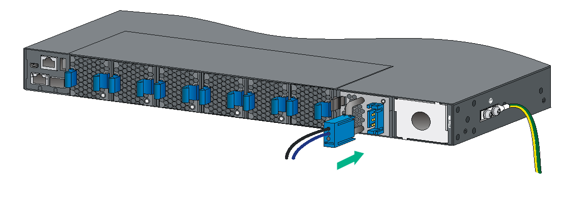
1. Align the power cord plug with the power receptacle on the power module, and insert the plug into the receptacle (see Figure 39).
The plug and receptacle are foolproof. If you cannot insert the plug into the receptacle, re-orient the plug rather than use excessive force to push it in.
2. Use a cable tie to secure the power cord to the handle of the power module, as shown in Figure 38.
3. Connect the other end of the power cord to the DC power source.
Figure 39 Connecting a DC power cord to the LSVM1DC650 power module
Installing/removing expansion cards
|
|
CAUTION: When you install or remove an expansion card, follow these guidelines: · Never touch the components on the expansion card surface with bare hands. · Do not use excessive force. |
The S6820-4C switch provides four expansion slots. For the available expansion cards, see "Appendix B FRUs."
The expansion card installation and removal procedures are the same. This section uses the LSWM18CQ interface card as an example.
Installing an expansion card
1. Wear an ESD wrist strap and make sure the wrist strap makes good skin contact and is reliably grounded.
2. (Optional.) If the target expansion slot has a filler panel installed, remove the filler panel, as shown in Figure 40.
a. Use your thumb and forefinger to hold the filler panel through the two holes.
b. Push right the metal tab in the left hole and pull out the filler panel along the guide rails.
Figure 40 Removing the filler panel from the expansion slot
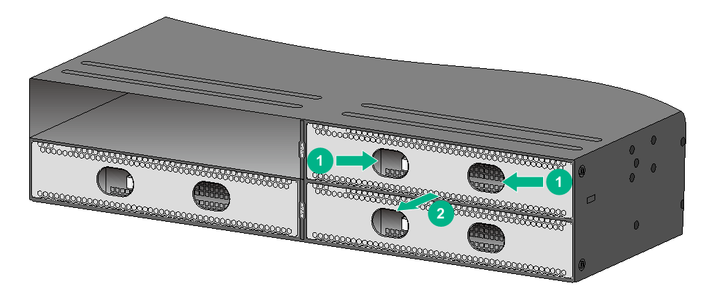
Keep the removed filler panel secure for future use.
3. Unpack the expansion card.
Figure 41 LSWM18CQ interface card
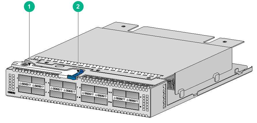
|
(1) Ejector lever |
(2) Latch |
4. Press the latch on the expansion card to release the ejector lever.
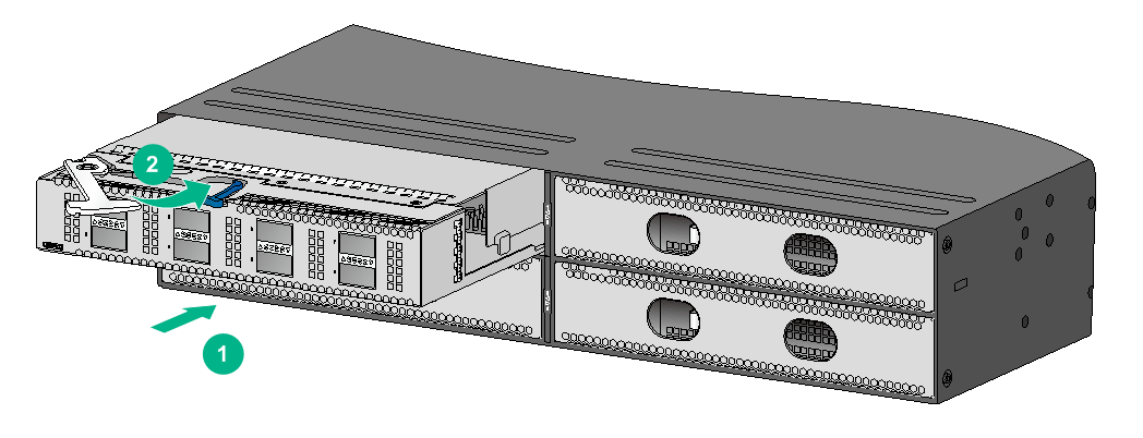
5. Insert the expansion card slowly into the slot along the guide rails, as shown by callout 1 in Figure 42.
6. Rotate inward the ejector lever as shown by callout 2 in Figure 42 until the latch locks the ejector lever in place.
Figure 42 Installing the LSWM18CQ interface card
Removing an expansion card
|
|
CAUTION: · Before you remove an expansion card, remove the cable from it to avoid cable damage. · If you are not to install a new expansion card after removing the original one, install the filler panel in the slot to prevent dust and ensure good ventilation in the device. |
To remove an expansion card:
1. Prepare an anti-static bag.
2. Wear an ESD wrist strap and make sure the wrist strap makes good skin contact and is reliably grounded.
3. Press the latch to release the ejector lever
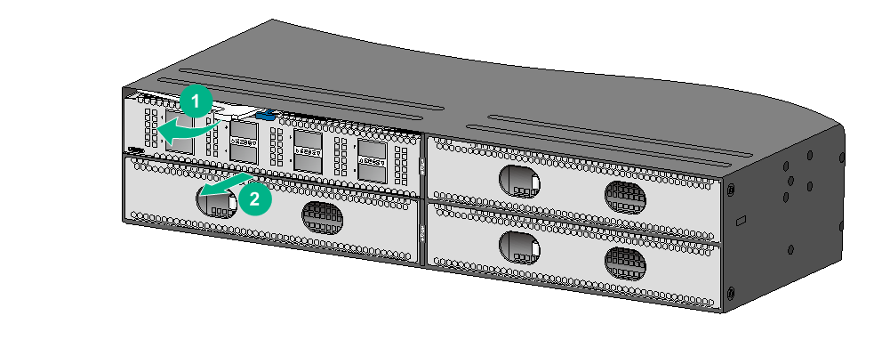
4. Rotate outward the ejector lever as shown by callout 1 in Figure 43.
5. Pull out the expansion card slowly out of the expansion slot, as shown by callout 2 in Figure 43.
6. Place the removed expansion card in the anti-static bag.
Figure 43 Removing an LSWM18CQ interface card
Verifying the installation
After you complete the installation, verify that:
· There is enough space for heat dissipation around the switch, and the rack is stable.
· The grounding cable is securely connected.
· The correct power source is used.
· The power cords are correctly connected.
· All the interface cables are cabled indoors. If any cable is routed outdoors, verify that the socket strip with lightning protection and lightning arresters for network ports have been correctly connected.
Accessing the switch for the first time
Setting up the configuration environment
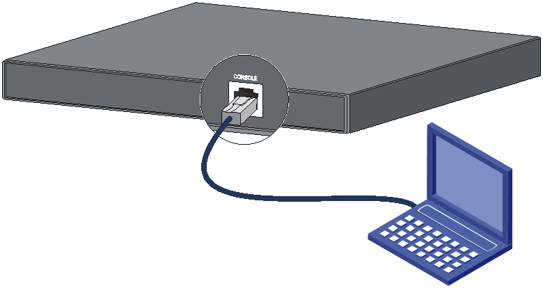
You can access the switch through the serial console port or the mini USB console port. As a best practice, use the serial console port to access the switch. To access the switch through the mini USB console port, you need to prepare a mini USB console cable yourself.
The example uses a console cable to connect a console terminal (PC) to the serial console port on the switch.
Figure 44 Connecting the serial console port to a terminal
Connecting the console cable
A serial console cable is an 8-core cable, with a crimped RJ-45 connector at one end for connecting to the serial console port of the switch, and a DB-9 female connector at the other end for connecting to the serial port on the console terminal.
Figure 45 Serial console cable
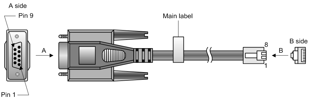
Table 5 Console port signaling and pinout
|
RJ-45 |
Signal |
DB-9 |
Signal |
|
1 |
RTS |
8 |
CTS |
|
2 |
DTR |
6 |
DSR |
|
3 |
TXD |
2 |
RXD |
|
4 |
SG |
5 |
SG |
|
5 |
SG |
5 |
SG |
|
6 |
RXD |
3 |
TXD |
|
7 |
DSR |
4 |
DTR |
|
8 |
CTS |
7 |
RTS |
To connect a terminal (for example, a PC) to the switch by using the serial console cable:
1. Plug the DB-9 female connector of the serial console cable to the serial port of the PC.
2. Connect the RJ-45 connector to the serial console port of the switch.
|
|
NOTE: · Identify the mark on the console port and make sure you are connecting to the correct port. · The serial ports on PCs do not support hot swapping. To connect a PC to an operating switch, first connect the PC end. To disconnect a PC from an operating switch, first disconnect the switch end. |
Connecting the mini USB console cable
A mini USB console cable has a USB mini-Type B connector at one end to connect to the mini USB console port of the switch, and a standard USB Type A connector at the other end to connect to the USB port on the configuration terminal.
To connect to the configuration terminal through the USB mini console cable:
1. Connect the standard USB Type A connector to the USB port of the configuration terminal.
2. Connect the USB mini Type B connector to the Mini USB console port of the switch.
3. Click the following link, or copy it to the address bar on the browser to log in to download page of the USB console driver, and download the driver.
4. Select a driver program according to the operating system you use:
¡ XR21V1410_XR21B1411_Windows_Ver1840_x86_Installer.EXE—32-bit operating system.
¡ XR21V1410_XR21B1411_Windows_Ver1840_x64_Installer.EXE—64-bit operating system.
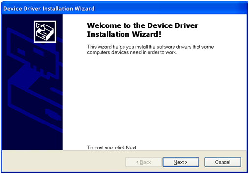
5. Click Next on the installation wizard.
Figure 46 Device Driver Installation Wizard
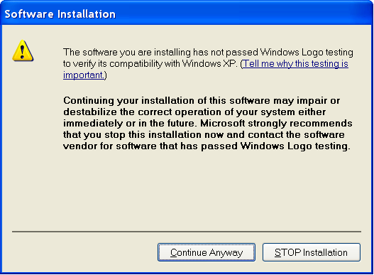
6. Click Continue Anyway if the following dialog box appears.
Figure 47 Software Installation
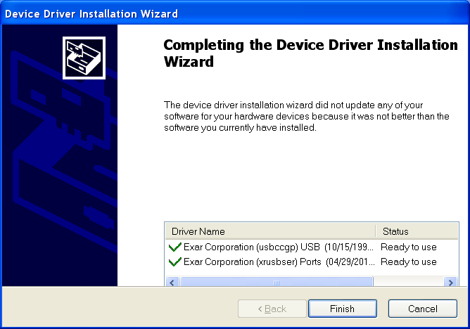
7. Click Finish.
Figure 48 Completing the device driver installation wizard
Setting terminal parameters
To configure and manage the switch through the console port, you must run a terminal emulator program, TeraTermPro or PuTTY, on your configuration terminal. You can use the emulator program to connect a network device, a Telnet site, or an SSH site. For more information about the terminal emulator programs, see the user guides for these programs
The following are the required terminal settings:
· Bits per second—9600.
· Data bits—8.
· Stop bits—1.
· Parity—None.
· Flow control—None.
Powering on the switch
1. Before powering on the switch, verify that the following conditions are met:
¡ All the fan tray slots have a fan tray installed.
¡ The power cords are connected correctly.
¡ The input power voltage is as required by the switch.
¡ The console cable is connected correctly.
¡ The configuration terminal (a PC, for example) has started, and its serial port settings are consistent with the console port settings on the switch.
2. Power on the switch.
During the startup process, you can access BootWare menus to perform tasks such as software upgrade and file management. The BootWare interface and menu options vary by software version. For more information about BootWare menu options, see the software-matching release notes for the device.
3. After the startup completes, you can access the CLI to configure the switch.
For more information about the configuration commands and CLI, see H3C S6820 Switch Series Configuration Guides and H3C S6820 Switch Series Command References.
Setting up an IRF fabric
You can use H3C IRF technology to connect and virtualize multiple S6820 switches into a large virtual switch called an "IRF fabric" for flattened network topology, and high availability, scalability, and manageability.
IRF fabric setup flowchart
Figure 49 IRF fabric setup flowchart
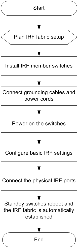
To set up an IRF fabric:
|
Step |
Description |
|
1. Plan IRF fabric setup. |
Plan the installation site and IRF fabric setup parameters: · Planning IRF fabric size and the installation site · Identifying the master switch and planning IRF member IDs · Planning IRF topology and connections |
|
2. Install IRF member switches. |
|
|
3. Connect ground wires and power cords. |
See "Grounding the switch" and "Connecting the power cord." |
|
4. Power on the switches. |
N/A |
|
5. Configure basic IRF settings. |
See H3C S6820 Switch Series IRF Configuration Guide. |
|
6. Connect the physical IRF ports. |
Connect the physical IRF ports on switches. Use QSFP28/QSFP+/SFP28 transceiver modules and fibers for connections over long distances. Use QSFP28/QSFP28 to SFP28/QSFP+/SFP28 cables for connections over short distances. All switches except the master switch automatically reboot, and the IRF fabric is established. |
Planning IRF fabric setup
This section describes issues that an IRF fabric setup plan must cover.
Planning IRF fabric size and the installation site
Determine the number of required IRF member switches, depending on the user density and upstream bandwidth requirements. The switching capacity of an IRF fabric equals the total switching capacities of all member switches.
Plan the installation site depending on your network solution as follows:
· Place all IRF member switches in one rack for centralized high-density access.
· Distribute the IRF member switches in different racks to implement the top-of-rack (ToR) access solution for a data center.
As your business grows, you can add member switches into the IRF fabric to increase the switching capacity without any topology change or replacement.
Identifying the master switch and planning IRF member IDs
Determine which switch you want to use as the master for managing all member switches in the IRF fabric. An IRF fabric has only one master switch. You configure and manage all member switches in the IRF fabric at the command line interface of the master switch.
|
|
NOTE: IRF member switches will automatically elect a master. You can affect the election result by assigning a high member priority to the intended master switch. For more information about master election, see H3C S6820 Switch Series IRF Configuration Guide. |
Prepare an IRF member ID assignment scheme. An IRF fabric uses member IDs to uniquely identify and manage its members, and you must assign each IRF member switch a unique member ID.
Planning IRF topology and connections
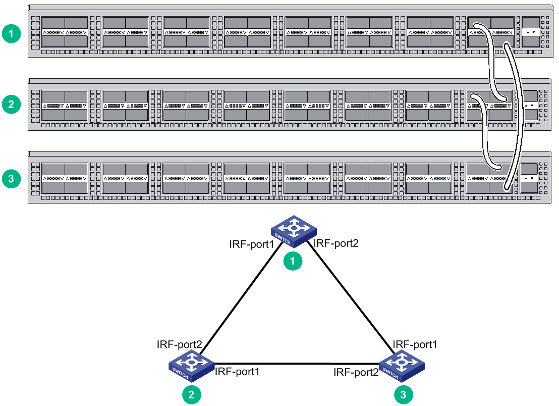
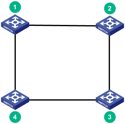
You can create an IRF fabric in daisy chain topology, or more reliably, ring topology. In ring topology, the failure of one IRF link does not cause the IRF fabric to split as in daisy chain topology. Rather, the IRF fabric changes to a daisy chain topology without interrupting network services.
You connect the IRF member switches through IRF ports, the logical interfaces for the connections between IRF member switches. Each IRF member switch has two IRF ports: IRF-port 1 and IRF-port 2. To use an IRF port, you must bind a minimum of one physical port to it.
When connecting two neighboring IRF member switches, you must connect the physical ports of IRF-port 1 on one switch to the physical ports of IRF-port 2 on the other switch.
The IRF port connections in the two figures are for illustration only, and more connection methods are available.
Figure 50 IRF fabric in daisy chain topology
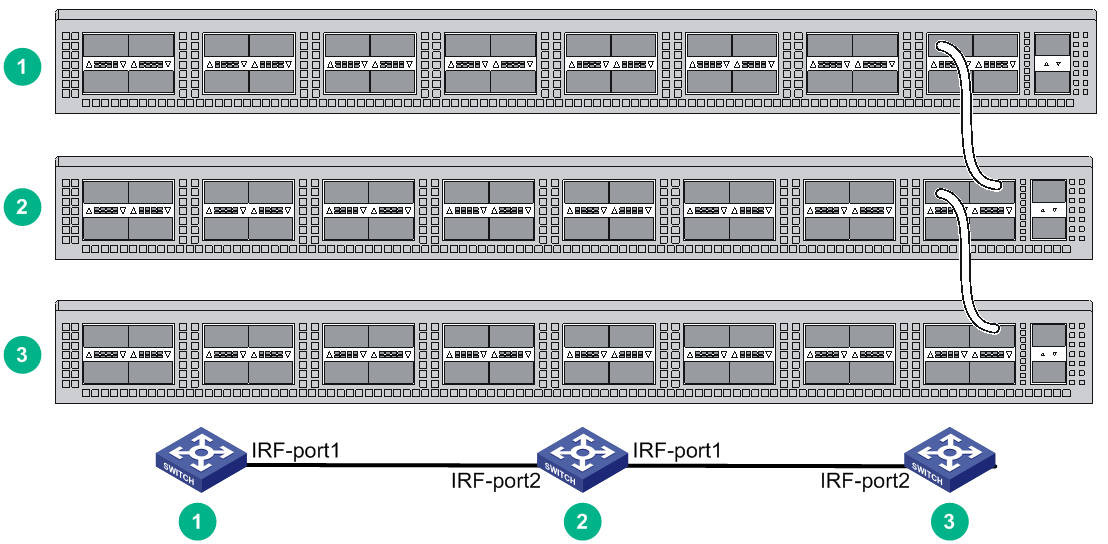
Figure 51 IRF fabric in ring topology
You can set up IRF links between S6820 switches as follows:
· Use a QSFP28 module and fiber or a QSFP28 cable to connect QSFP28 ports for a 100-GE IRF physical connection.
· Use a QSFP+ module and fiber or a QSFP+ cable to connect QSFP28 ports for a 40-GE IRF physical connection.
· Use a 100G QSFP28 to 4 × 25G SFP28 cable to connect a QSFP28 port to four 25G SFP28 ports.
· Use a QSFP+ module and fiber or a QSFP+ cable to connect QSFP+ ports for a 40-GE IRF connection.
· Use an SFP28 module and fiber or an SFP28 cable to connect SFP28 ports for a 25-GE IRF connection.
You can bind several ports to an IRF port for increased bandwidth and availability.
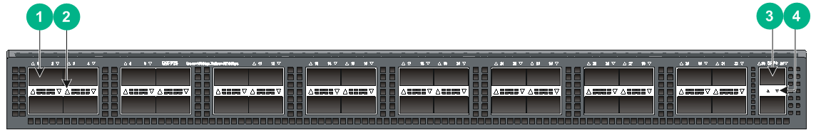
Identifying physical IRF ports on the member switches
Identify the physical ports for IRF connections on the member switches according to your topology and connection scheme.
All the QSFP28, QSFP+, and SFP28 ports on the switch can be used for IRF connections, except for QSFP28 ports on the LSWM18CQMSEC interface module.
When you select ports in a port group for IRF links, you must use all or none of the ports in the group for IRF links. The ports in a group can be bound to different IRF ports.
The port grouping rules are as follows:
· The S6820-56HF switch has two port ranges. Ports numbered 1 to 24 are in one range and ports numbered 33 to 56 are in the other range. In each range, the ports are grouped by port number in order, starting from the lowest number. Each group contains four ports.
· On an LSWM124TG2H module, the ports numbered 1 to 24 are grouped by port number in order, starting from the lowest number. Each group contains four ports.
· On an LSWM116Q module, odd and even numbered ports are separated for grouping. The ports are grouped by port number in order, starting from the lowest odd or even number. Each group contains two ports with consecutive odd or even port numbers.
· The four 25-GE breakout interfaces of a 100-GE port are in one port group. To split a 100-GE port, use the using twenty-fivegige command.
· Except the LSWM116Q module, if you use a 40-GE or 100-GE port that is not split for IRF links, no grouping restrictions exist.
Planning the cabling scheme
You can use QSFP28/QSFP28 to SFP28/QSFP+/SFP28 cables, or QSFP28/QSFP+/SFP28 transceiver modules and fibers to connect the S6820 switches for IRF connections.
If the switches are all in one equipment room, choose QSFP28/QSFP28 to SFP28/QSFP+/SFP28 cables for IRF connections. If the switches are far away from one another, choose QSFP28/QSFP+/SFP28 transceiver modules and fibers for IRF connections.
For more information about available cables, see "Appendix C Ports and LEDs."
The following subsections describe several IRF connection schemes by using the QSFP28 cables and QSFP28 transceiver modules and fibers. As a best practice, use the ring topology for IRF connections.
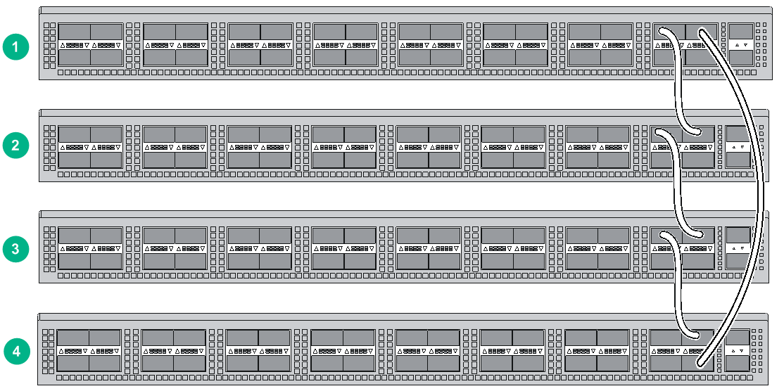
Connecting the IRF member switches in one rack
Figure 52 shows an example for connecting four IRF member switches in a rack. The switches in the ring topology (see Figure 53) are in the same order as connected in the rack.
Figure 52 Connecting the switches in one rack
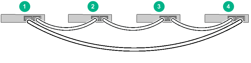
Connecting the IRF member switches in a ToR solution
You can install IRF member switches in different racks side by side to deploy a top of rack (ToR) solution.
Figure 54 shows an example for connecting four top of rack IRF member switches. The topology is the same as Figure 53.
Configuring basic IRF settings
After you install the IRF member switches, power on the switches, and log in to each IRF member switch (see H3C S6820 Switch Series Fundamentals Configuration Guide) to configure their member IDs, member priorities, and IRF port bindings.
Follow these guidelines when you configure the switches:
· Assign the master switch higher member priority than any other switch.
· Bind physical ports to IRF port 1 on one switch and to IRF port 2 on the other switch. You perform IRF port binding before or after connecting IRF physical ports depending on the software release.
· Execute the display irf configuration command to verify the basic IRF settings.
For more information about configuring basic IRF settings, see H3C S6820 Switch Series IRF Configuration Guide.
Connecting the physical IRF ports
|
|
CAUTION: Wear an ESD wrist strap when you install transceiver modules, fibers, and cables. For more information, see the installation guide. |
Use transceiver modules and fibers or cables to connect the IRF member switches as planned.
Accessing the IRF fabric to verify the configuration
To verify the basic functionality of the IRF fabric after you finish configuring basic IRF settings and connecting IRF ports:
1. Log in to the IRF fabric through the console port of any member switch.
2. Create a Layer 3 interface, assign it an IP address, and make sure the IRF fabric and the remote network management station can reach each other.
3. Use Telnet or SNMP to access the IRF fabric from the network management station. (See H3C S6820 Switch Series Fundamentals Configuration Guide.)
4. Verify that you can manage all member switches as if they were one node.
5. Display the running status of the IRF fabric by using the commands in Table 6.
Table 6 Displaying and maintaining IRF configuration and running status
|
Task |
Command |
|
Display information about the IRF fabric. |
display irf |
|
Display all members' IRF configurations. |
display irf configuration |
|
Display IRF fabric topology information. |
display irf topology |
|
|
NOTE: To avoid IP address collision and network problems, configure at least one multi-active detection (MAD) mechanism to detect the presence of multiple identical IRF fabrics and handle collisions. For more information about MAD detection, see H3C S6820 Switch Series IRF Configuration Guide. |
Maintenance and troubleshooting
Power module failure
Symptom
The power module status LED on a power module is not steady green (active state) or flashing green (standby state)
For more information about the LEDs on a power module, see H3C LSVM1AC650 & LSVM1DC650 Power Modules User Manual.
Solution
To resolve the issue:
1. Verify that the power cord is connected correctly.
2. Verify that the power source is as required by the switch.
3. Verify that the operating temperature of the switch is in the acceptable range and the power module has good ventilation.
4. If the issue persists, contact H3C Support.
To replace a power module, see "Installing/removing power modules."
Fan tray failure
|
|
CAUTION: The S6820-32H switch has six fan tray slots. The S6820-56HF switch has five fan tray slots. The S6820-4C switch has two fan tray slots. To replace failed fan trays on an operating switch, follow these guidelines: · If multiple fan trays fail on an operating S6820-32H or S6820-56HF switch, do not remove the fan trays at the same time. Replace the fan trays one after another and finish replacing a fan tray within 3 minutes. · If a fan tray fails on an operating S6820-4C switch, replace the fan tray immediately and keep the failed fan tray in position before replacement. If two fan trays fail, finish replacing the fan trays within 1 minute. |
Symptom
· The status LED on an LSWM1FANSA or LSWM1FANSAB fan tray is steady orange and the system outputs alarm messages.
· The status LED on an LSWM1BFANSC or LSWM1BFANSCB fan tray is steady yellow and the system outputs alarm messages.
Solution
See "Installing/removing fan trays" to replace the fan tray. If the problem persists, contact H3C Support.
Configuration terminal display problems
No display
Symptom
The configuration terminal displays nothing when the switch is powered on.
Solution
To resolve the issue:
1. Verify that the power system is operating correctly.
2. Verify that the console cable is connected correctly.
3. Verify that the console cable does not have any problems and the terminal settings are correct.
4. If the issue persists, contact H3C Support.
Garbled display
Symptom
The configuration terminal has a garbled display.
Solution
To resolve the issue:
1. Verify that the following settings are configured for the terminal:
¡ Baud rate—9,600.
¡ Data bits—8.
¡ Parity—None.
¡ Stop bits—1.
¡ Flow control—None.
2. If the issue persists, contact H3C Support.
Appendix A Chassis views and technical specifications
Chassis views
S6820-32H
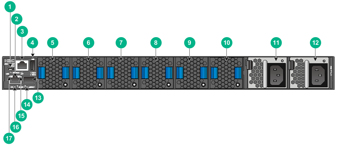
Figure 55 Front panel
|
(1) QSFP28 port |
(2) QSFP28 port LED |
|
(3) SFP+ port |
(4) SFP+ port LED |
|
(1) Mini USB console port |
(2) Copper management Ethernet port |
|
(3) Serial console port |
(4) USB port |
|
(5) Fan tray 1 |
(6) Fan tray 2 |
|
(7) Fan tray 3 |
(8) Fan tray 4 |
|
(9) Fan tray 5 |
(10) Fan tray 6 |
|
(11) Power module 1 |
(12) Power module 2 |
|
(13) Fiber management Ethernet port |
|
|
(14) Fiber Management Ethernet port LED (LINK/ACT) |
|
|
(15) Copper management Ethernet port LED (ACT) |
(16) System status LED (SYS) |
|
(17) Copper management Ethernet port LED (LINK) |
|
The S6820-32H switch comes with power module slot PWR1 empty and power module slot PWR2 installed with a filler panel. You can install one or two power modules for the switch as needed. In Figure 56, two LSVM1AC650 power modules are installed in the power module slots.
The S6820-32H switch comes with the six fan tray slots empty. You must install six fan trays of the same model for the switch. In Figure 56, six LSWM1FANSA fan trays are installed in the fan tray slots.
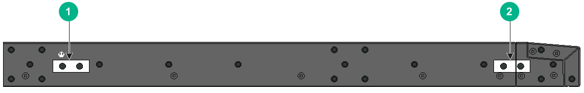
Figure 57 Left panel
|
(1) Primary grounding point |
(2) Auxiliary grounding point |
S6820-56HF
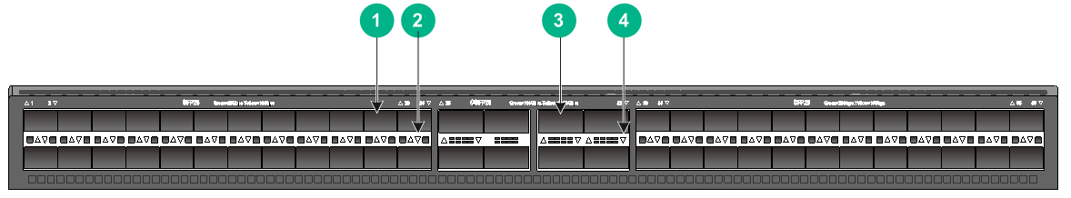
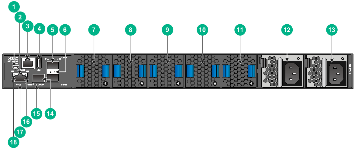
Figure 58 Front panel
|
(1) SFP28 port |
(2) SFP28 port LED |
|
(3) QSFP28 port |
(4) QSFP28 port LED |
|
(1) Mini USB console port |
(2) Copper management Ethernet port |
|
(3) Serial console port |
(4) USB port |
|
(5) SFP port |
(6) SFP port LED |
|
(7) Fan tray 1 |
(8) Fan tray 2 |
|
(9) Fan tray 3 |
(10) Fan tray 4 |
|
(11) Fan tray 5 |
(12) Power module 1 |
|
(13) Power module 2 |
(14) Fiber management Ethernet port |
|
(15) Fiber management Ethernet port LED (LINK/ACT) |
|
|
(16) Copper Management Ethernet port LED (ACT) |
(17) System status LED (SYS) |
|
(18) Copper management Ethernet port LED (LINK) |
|
The S6820-56HF switch comes with power module slot PWR1 empty and power module slot PWR2 installed with a filler panel. You can install one or two power modules for the switch as needed. In Figure 59, two LSVM1AC650 power modules are installed in the power module slots.
The S6820-56HF switch comes with the five fan tray slots empty. You must install five fan trays of the same model for the switch. In Figure 59, five LSWM1FANSA fan trays are installed in the fan tray slots.
The S6820-56HF switch comes with a dust plug in the fiber management Ethernet port on the rear panel. To use the fiber management Ethernet port, first remove the dust plug. In Figure 59, the dust plug has been removed from the fiber management Ethernet port.
Figure 60 Left panel
|
(1) Primary grounding point |
(2) Auxiliary grounding point |
S6820-4C
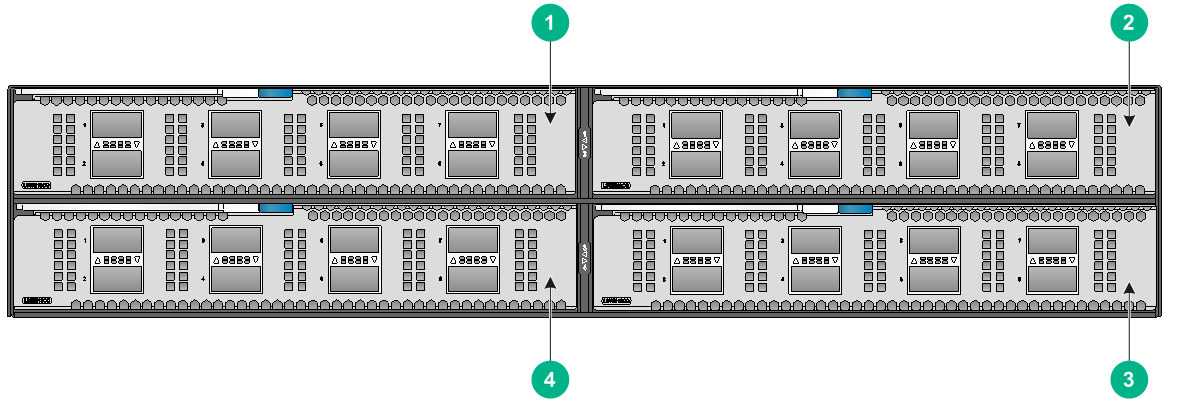
|
(1) Expansion card 1 |
(2) Expansion card 2 |
|
(3) Expansion card 4 |
(4) Expansion card 3 |
|
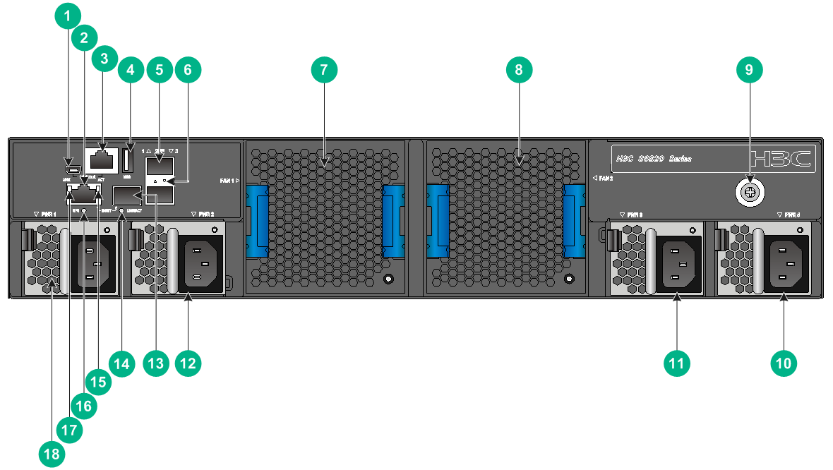
(1) Mini USB console port |
(2) Copper management Ethernet port |
|
(3) Serial console port |
(4) USB port |
|
(5) SFP port |
(6) SFP port LED |
|
(7) Fan tray 1 |
(8) Fan tray 2 |
|
(9) Grounding screw (auxiliary grounding point 2) |
(10) Power module 4 |
|
(11) Power module 3 |
(12) Power module 2 |
|
(13) Fiber management Ethernet port |
|
|
(14) Fiber management Ethernet port LED (LINK/ACT) |
|
|
(15) Copper management Ethernet port LED (ACT) |
(16) System status LED (SYS) |
|
(17) Copper management Ethernet port LED (LINK) |
(18) Power module 1 |
The S6820-4C switch comes with expansion slot 1 empty and the other three expansion slots each installed with a filler panel. You can install one to four expansion cards for the switch as needed. In Figure 61, four LSWM18CQ interface cards are installed in the expansion slots.
The S6820-4C switch comes with power module slots PWR2 and PWR3 empty and the other two power module slots each installed with a filler panel. You can install two to four power modules for the switch as needed. In Figure 62, four LSVM1AC650 power modules are installed in the power module slots.
The S6820-4C switch comes with the two fan tray slots empty. You must install two fan trays of the same model for the switch. In Figure 62, two LSWM1BFANSC fan trays are installed in the fan tray slots.
Figure 63 Left panel
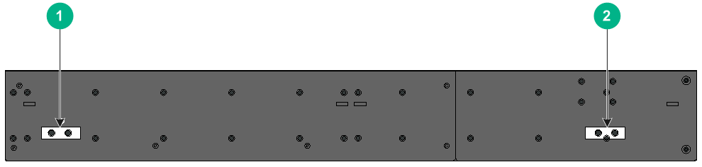
|
(1) Primary grounding point |
(2) Auxiliary grounding point 1 |
Technical specifications
Table 7 Technical specifications
|
Item |
S6820-32H |
S6820-56HF |
S6820-4C |
|
Dimensions (H × W × D) |
43.6 × 440 × 540 mm (1.72 × 17.32 × 21.26 in) |
43.6 × 440 × 460 mm (1.72 × 17.32 × 18.11 in) |
88.1 × 440 × 660 mm (3.47 × 17.32 × 25.98 in) |
|
Weight |
≤ 15 kg (33.07 lb) |
≤ 15 kg (33.07 lb) |
≤ 27 kg (59.52 lb) |
|
Console port |
· 1 × Mini USB console port · 1 × serial console port |
· 1 × Mini USB console port · 1 × serial console port |
· 1 × Mini USB console port · 1 × serial console port |
|
Management Ethernet port |
· 1 × 10M/100M/1000M Base-T copper port · 1 × SFP port |
· 1 × 10M/100M/1000M Base-T copper port · 1 × SFP port |
· 1 × 10M/100M/1000M Base-T copper port · 1 × SFP port |
|
USB port |
1 |
1 |
1 |
|
SFP port |
N/A |
2 |
2 |
|
SFP+ port |
2 |
N/A |
N/A |
|
SFP28 port |
N/A |
48 |
N/A |
|
QSFP28 port |
32 |
8 |
N/A |
|
Fan tray slot |
6 |
5 |
2 |
|
Power module slot |
2 |
2 |
4 |
|
Expansion slot |
N/A |
N/A |
4 |
|
Minimum power consumption |
· Single AC input: 280 W · Dual AC inputs: 286 W · Single DC input: 270 W · Dual DC inputs: 275 W |
· Single AC input: 188 W · Dual AC inputs: 200 W · Single DC input: 180 W · Dual DC inputs: 195 W |
· Dual AC inputs: 180 W · Triple AC inputs: 197 W · Quadruple AC inputs: 213 W · Dual DC inputs: 187 W · Triple DC inputs: 202 W · Quadruple DC inputs: 213 W |
|
Maximum power consumption |
· Single AC input: 586 W · Dual AC inputs: 590 W · Single DC input: 582 W · Dual DC inputs: 572 W |
· Single AC input: 405 W · Dual AC inputs: 413 W · Single DC input: 400 W · Dual DC inputs: 408 W |
· Dual AC inputs: 612 W · Triple AC inputs: 618 W · Quadruple AC inputs: 635 W · Dual DC inputs: 610 W · Triple DC inputs: 612 W · Quadruple DC inputs: 613 W |
|
Chassis leakage current compliance |
· UL60950-1 · EN60950-1 · IEC60950-1 · GB4943 |
||
|
Operating temperature |
0°C to 45°C (32°F to 113°F) |
||
|
Operating humidity |
5% to 95%, noncondensing |
||
|
Fire resistance compliance |
· UL60950-1 · EN60950-1 · IEC60950-1 · GB4943 |
||
Appendix B FRUs
The switch uses modular design. Table 8 describes the FRUs available for the switch.
Table 8 FRUs available for the switch
|
FRUs |
S6820-32H |
S6820-56HF |
S6820-4C |
|
Power modules |
|||
|
LSVM1AC650 |
Yes |
Yes |
Yes |
|
LSVM1DC650 |
Yes |
Yes |
Yes |
|
Fan trays |
|||
|
LSWM1FANSA |
Yes |
Yes |
No |
|
LSWM1FANSAB |
Yes |
Yes |
No |
|
LSWM1BFANSC |
No |
No |
Yes |
|
LSWM1BFANSCB |
No |
No |
Yes |
|
Expansion cards |
|||
|
LSWM18CQ |
No |
No |
Yes |
|
LSWM18CQMSEC |
No |
No |
Yes |
|
LSWM116Q |
No |
No |
Yes |
|
LSWM18QC |
No |
No |
Yes |
|
LSWM124XG2Q |
No |
No |
Yes |
|
LSWM124XGT2Q |
No |
No |
Yes |
|
LSWM124XG2QFC |
No |
No |
Yes |
|
LSWM124XG2QL |
No |
No |
Yes |
|
LSWM124TG2H |
No |
No |
Yes |
The S6820-32H and S6820-56HF switches can operate correctly with only one power module. You can install two power modules on the switch for 1+1 redundancy.
The S6820-4C switch can operate correctly with two power modules. You can install four power modules on the switch for 2+2 redundancy.
To ensure heat dissipation, make sure all fan tray slots on the switch have fan trays installed and the fan trays are the same model.
Power modules
|
|
CAUTION: When the switch has power modules in redundancy, you can replace a power module without powering off the switch. Make sure the power module to be replaced is powered off before you replace it. |
Table 9 Power module specifications
|
Power module model |
Specifications |
Remarks |
|
LSVM1AC650 |
· Rated input voltage: 100 VAC to 240 VAC @ 50 Hz or 60 Hz · Max input voltage: 90 VAC to 264 VAC @ 47 Hz to 63 Hz · Max output power: 650 W · Melting current of the fuse: 10 A/250 V |
For more information about the power modules, see H3C LSVM1AC650 & LSVM1DC650 Power Modules User Manual. |
|
LSVM1DC650 |
· Rated input voltage: –40 VDC to –60 VDC · Max input voltage: –40 VDC to –72 VDC · Max output power: 650 W · Melting current of the fuse: 30 A/250 V |
Fan trays
Table 10 Fan tray specifications
|
Fan tray model |
Item |
Specifications |
|
· LSWM1FANSA (from the power module side to the port side) · LSWM1FANSAB (from the port side to the power module side) |
Dimensions |
40.6 × 42.5 × 118.7 mm (1.60 × 1.67 × 4.67 in) |
|
Fan speed |
21000 R.P.M |
|
|
Max airflow |
35 CFM |
|
|
Input voltage |
12 V |
|
|
Maximum power consumption |
30 W |
|
|
Documentation reference |
H3C LSWM1FANSA & LSWM1FANSAB Fan Tray User Guide |
|
|
· LSWM1BFANSC (from the power module side to the port side) · LSWM1BFANSCB (from the port side to the power module side) |
Dimensions |
80 × 80 × 76 mm (3.15 × 3.15 × 2.99 in) |
|
Fan speed |
20000 R.P.M |
|
|
Max airflow |
120 CFM |
|
|
Input voltage |
12 V |
|
|
Maximum power consumption |
57 W |
|
|
Documentation reference |
H3C LSWM1BFANSC & LSWM1BFANSCB Fan trays User Guide |
Expansion cards
The S6820-4C switch provides four expansion slots. Select expansion cards for the switch as required.
Table 11 Interface cards available for the S6820-4C switch
|
Interface card model |
Interface card name |
Interface number and type |
Transceiver modules available for the ports |
|
LSWM18CQ |
8-Port QSFP28 Interface Module |
8 × QSFP28 ports |
· For the transceiver modules and cables available for the SFP+ ports, see "SFP+ port". · For the transceiver modules and cables available for the QSFP+ ports, see Table 23, Table 24, Table 26, and Table 26. · For the transceiver modules and cables available for the QSFP28 ports, see "QSFP28 port." · For the transceiver modules and cables available for the SFP28 ports, see "SFP28 port." |
|
LSWM18CQMSEC |
8-Port QSFP28 Interface Module with MACSec |
8 × QSFP28 ports |
|
|
LSWM116Q |
16-Port QSFP Plus Interface Module |
16 × QSFP+ ports |
|
|
LSWM18QC |
8-Port QSFP Plus Interface Card |
8 × QSFP+ ports |
|
|
LSWM124XGT2Q |
24-Port 10GBASE-T and 2-Port QSFP Plus Interface Card with MACSec |
· 24 × 10-GE copper ports · 2 × QSFP+ ports |
|
|
LSWM124XG2Q |
24-Port SFP Plus and 2-Port QSFP Plus Interface Card with MACSec |
· 24 × SFP+ ports · 2 × QSFP+ ports |
|
|
LSWM124XG2QL |
24-Port SFP Plus and 2-Port QSFP Plus Interface Card |
||
|
LSWM124XG2QFC |
24 Ports SFP Plus and 2 Ports QSFP Plus Interface Card with FC |
||
|
LSWM124TG2H |
24-Port SFP28 and 2-Port QSFP28 Interface Module |
· 24 × SFP28 ports · 2 × QSFP28 ports |
|
|
NOTE: · The QSFP+ ports on the LSWM116Q interface card cannot be split into four SFP+ ports. · Only F6203 and later versions support installation of 1G SFP modules in SFP28 ports. · Only F6205P05 and later versions support installation of 1G SFP modules in SFP+ ports. · An LSWM124XG2QL that has 1G SFP modules installed does not support rate and duplex autonegotiation. You must configure the speed 1000 and duplex full commands. · Only F6205P02 and later versions support the LSWM18CQMSEC interface cards. |
Appendix C Ports and LEDs
As a best practice, use H3C transceiver modules and cables for the switch. H3C transceiver modules and cables are subject to change over time. For the most up-to-date list of H3C transceiver modules and cables, contact H3C Support or marketing staff. For information about the specifications and views of H3C transceiver modules and cables, see H3C Transceiver Modules User Guide.
Ports
Console port
The switch has two console ports: one serial console port and one mini USB console port.
Table 12 Console port specifications
|
Item |
Console port |
Mini USB console port |
|
Connector type |
RJ-45 |
USB mini-Type B |
|
Compliant standard |
EIA/TIA-232 |
USB 2.0 |
|
Transmission baud rate |
9600 bps (default) to 115200 bps |
|
|
Services |
· Provides connection to an ASCII terminal. · Provides connection to the serial port of a local or remote (through a pair of modems) PC running terminal emulation program. |
· Provides connection to an ASCII terminal. · Provides connection to the USB port of a local PC running terminal emulation program. |
Management Ethernet port
The switch has two management Ethernet ports: one copper management port and one SFP management port. You can connect the ports to a local PC for software loading and debugging or to a remote management station for remote management.
Table 13 Management Ethernet port specifications
|
Item |
Specification |
|
Connector type |
· 10/100/1000BASE-T management port: RJ-45. · SFP management port: LC. |
|
Port transmission rate |
· 10/100/1000BASE-T management port: ¡ 10/100 Mbps, half/full duplex, MDI/MDI-X auto-sensing. ¡ 1000 Mbps, full duplex, MDI/MDI-X auto-sensing. · SFP management port: 1000/100 Mbps, full duplex. |
|
Transmission medium and max transmission distance |
· 10/100/1000BASE-T management port: 100 m (328.08 ft) over category-5 UTP cable. · SFP management port: See 100-Megabit transceiver modules in Table 14 and Gigabit transceiver modules in Table 18. |
|
Functions and services |
Software and BootWare upgrade and network management. |
FE SFP modules
Table 14 FE SFP transceiver modules
|
FE SFP transceiver module |
Central wavelength (nm) |
Connector |
Fiber type and diameter (µm) |
Max transmission distance |
|
SFP-FE-SX-MM1310-A |
1310 |
LC |
Multi-mode, 50/125 |
2 km (1.24 miles) |
|
Multi-mode, 62.5/125 |
||||
|
SFP-FE-LX-SM1310-A |
1310 |
LC |
Single-mode, 9/125 |
15 km (9.32 miles) |
|
SFP-FE-LH40-SM1310 |
1310 |
LC |
Single-mode, 9/125 |
40 km (24.86 miles) |
USB port
The switch has one OHCI-compliant USB 2.0 port that can upload and download data at a rate up to 480 Mbps. You can use this USB port to access the file system on the Flash of the switch, for example, to upload or download application and configuration files.
The USB port supplies power as per USB 2.0 specifications. Use only USB 2.0-compliant USB devices for the USB port. The port might not identity USB devices that are not compliant with USB 2.0.
|
|
NOTE: USB devices from different vendors vary in compatibilities and drivers. H3C does not guarantee correct operation of USB devices from other vendors on the switch. If a USB device fails to operate on the switch, replace it with one from another vendor. |
SFP+ port
The S6820-32H switch provides two SFP+ ports. The LSWM124XG2Q, LSWM124XG2QFC, and LSWM124XG2QL each provides 24 SFP+ ports. The SFP+ ports support the following transceiver modules and cables:
· 10-GE SFP+ transceiver modules in Table 15.
· 10-GE SFP+ copper cables in Table 16.
· 10-GE SFP+ fiber cables in Table 17.
· GE SFP transceiver modules in Table 18.
Table 15 10-GE SFP+ transceiver modules available for the SFP+ ports
|
10-GE SFP+ transceiver module |
Central wavelength (nm) |
Connector |
Fiber type and diameter (µm) |
Modal bandwidth (MHz × km) |
Max transmission distance |
|
SFP-XG-SX-MM850-A |
850 |
LC |
Multi-mode, 50/125 |
2000 |
300 m (984.25 ft) |
|
500 |
82 m (269.03 ft) |
||||
|
400 |
66 m (216.54 ft) |
||||
|
Multi-mode, 62.5/125 |
200 |
33 m (108.27 ft) |
|||
|
160 |
26 m (85.30 ft) |
||||
|
SFP-XG-LX-SM1310 |
1310 |
LC |
Single-mode, 9/125 |
N/A |
10 km (6.21 miles) |
|
SFP-FC-8G-SW-MM850 |
850 |
LC |
Multi-mode, 62.5/125 |
200 |
150 m (492.13 ft) |
|
Multi-mode, 50/125 |
500 |
380 m (1246.72 ft) |
|||
|
2000 |
500 m (1640.42 ft) |
||||
|
SFP-FC-8G-LW-SM1310 |
1310 |
LC |
Single-mode, 9/125 |
N/A |
10 km (6.21 miles) |
Table 16 10-GE SFP+ copper cables available for the SFP+ ports
|
10-GE SFP+ copper cable |
Max transmission distance |
|
LSWM1STK |
0.65 m (2.13 ft) |
|
LSWM2STK |
1.2 m (3.94 ft) |
|
LSWM3STK |
3 m (9.84 ft) |
|
LSTM1STK |
5 m (16.40 ft) |
Table 17 10-GE SFP+ fiber cables available for the SFP+ ports
|
10-GE SFP+ fiber cable |
Max transmission distance |
|
SFP-XG-D-AOC-7M |
7 m (22.97 ft) |
|
SFP-XG-D-AOC-10M |
10 m (32.81 ft) |
|
SFP-XG-D-AOC-20M |
20 m (65.62 ft) |
Table 18 GE SFP transceiver modules available for the SFP+ ports
|
GE SFP transceiver module |
Central wavelength (nm) |
Connector |
Cable/Fiber type and diameter (µm) |
Modal bandwidth (MHz × km) |
Max transmission distance |
|
SFP-GE-T |
N/A |
RJ-45 |
Twisted pair cable |
N/A |
100 m (328.08 ft) |
|
SFP-GE-SX-MM850-A |
850 |
LC |
Multi-mode, 50/125 |
500 |
550 m (1804.46 ft) |
|
400 |
500 m (1640.42 ft) |
||||
|
Multi-mode, 62.5/125 |
200 |
275 m (902.23 ft) |
|||
|
160 |
220 m (721.78 ft) |
||||
|
SFP-GE-LX-SM1310-A |
1310 |
LC |
Single-mode, 9/125 |
N/A |
10 km (6.21 miles) |
|
Multi-mode, 50/125 |
500 or 400 |
550 m (1804.46 ft) |
|||
|
Multi-mode, 62.5/125 |
500 |
550 m (1804.46 ft) |
|||
|
SFP-GE-LH40-SM1310 |
1310 |
LC |
Single-mode, 9/125 |
N/A |
40 km (24.86 miles) |
|
SFP-GE-LH40-SM1550 |
1550 |
LC |
Single-mode, 9/125 |
N/A |
40 km (24.86 miles) |
|
SFP-GE-LH80-SM1550 |
1550 |
LC |
Single-mode, 9/125 |
N/A |
80 km (49.71 miles) |
|
|
IMPORTANT: · When a GE SFP module is installed in an SFP+ port on the LSWM124XG2QL interface card, the SFP+ port does not support rate and duplex autonegotiation. You must configure the speed 1000 and duplex full commands on both ends. · Only F6205P05 and later versions support installation of GE SFP modules in SFP+ ports. · Only the SFP+ ports on the LSWM124XG2QFC interface card support SFP-FC-8G-SW-MM850 and SFP-FC-8G-LW-SM1310 modules. · Only F6202 and later versions support SFP-FC-8G-SW-MM850 and SFP-FC-8G-LW-SM1310 modules. |
SFP port
The S6820-56HF and S6820-4C switches each provide two SFP ports. You can install FE SFP transceiver modules in Table 14 and GE SFP transceiver modules in Table 18 in the SFP ports as needed.
QSFP28 port
The S6820-32H provides 32 QSFP28 ports, and the S6820-56HF provides 8 QSFP28 ports. The LSWM18CQ and LSWM18CQMSEC each provide 8 QSFP28 ports and the LSWM124TG2H provides 2 QSFP28 ports. You can install the following transceiver modules and cables in the QSFP28 ports:
· QSFP28 transceiver modules in Table 19.
· QSFP28 copper cables in Table 20.
· QSFP28 fiber cables in Table 21.
· QSFP28 to SFP28 copper cables in Table 22.
· QSFP+ transceiver modules in Table 23.
· QSFP+ copper cables in Table 24.
· QSFP+ fiber cables in Table 25.
· QSFP+ to SFP+ copper cables in Table 26.
Table 19 QSFP28 transceiver modules available for the QSFP28 ports
|
QSFP28 transceiver module |
Central wavelength (nm) |
Connector |
Fiber type and diameter (µm) |
Modal bandwidth (MHz*km) |
Maximum transmission distance |
|
QSFP-100G-SR4-MM850 |
850 |
MPO (PC polished, 12-fiber) |
Multi-mode, 50/125 |
2000 |
70 m (229.66 ft) |
|
4700 |
100 m (328.08 ft) |
||||
|
QSFP-100G-PSM4-SM1310 |
1295 to 1325 |
MPO (APC polished, 12-fiber) |
Single-mode, 9/125 |
N/A |
500 m (1640.42 ft) |
|
QSFP-100G-LR4-WDM1300 |
Four lanes: · 1295 · 1300 · 1304 · 1309 |
LC |
Single-mode, 9/125 |
N/A |
10 km (6.21 miles) |
|
QSFP-100G-LR4L-WDM1300 |
Four lanes: · 1264.5 to 1277.5 · 1284.5 to 1297.5 · 1304.5 to 1317.5 · 1324.5 to 1337.5 |
LC |
Single-mode, 9/125 |
N/A |
2 km (1.24 miles) |
|
QSFP-100G-ER4L-WDM1300 |
Four lanes: · 1294.53 to 1296.59 · 1299.02 to 1301.09 · 1303.54 to 1305.63 · 1308.09 to 1310.19 |
SMF |
Single-mode, 9/125 |
N/A |
40 km (24.86 miles) |
|
QSFP-100G-SWDM4-MM850 |
Four lanes: · 850 · 880 · 910 · 940 |
MMF |
Multi-mode, 50/125 |
2000 |
75 m (246.06 ft) |
|
4700 |
100 m (328.08 ft) |
Table 20 QSFP28 copper cables available for the QSFP28 ports
|
QSFP28 copper cable |
Cable length |
|
QSFP-100G-D-CAB-1M |
1 m (3.28 ft) |
|
QSFP-100G-D-CAB-3M |
3 m (9.84 ft) |
|
QSFP-100G-D-CAB-5M |
5 m (16.40 ft) |
Table 21 QSFP28 fiber cables available for the QSFP28 ports
|
QSFP28 fiber cable |
Cable length |
|
QSFP-100G-D-AOC-7M |
7 m (22.97 ft) |
|
QSFP-100G-D-AOC-10M |
10 m (32.81 ft) |
|
QSFP-100G-D-AOC-20M |
20 m (65.62 ft) |
Table 22 QSFP28 to SFP28 copper cables available for the QSFP28 ports
|
QSFP28 to SFP28 copper cable |
Cable length |
|
QSFP-100G-4SFP-25G-CAB-1M |
1 m (3.28 ft) |
|
QSFP-100G-4SFP-25G-CAB-3M |
3 m (9.84 ft) |
Table 23 QSFP+ transceiver modules available for the QSFP+ and QSFP28 ports
|
Central wavelength (nm) |
Connector |
Fiber type and diameter (µm) |
Modal bandwidth (MHz × km) |
Max transmission distance |
|
|
QSFP-40G-SR4-MM850 |
850 |
MPO (PC-polished, 12-core) |
Multi-mode, 50/125 |
2000 |
100 m (328.08 ft) |
|
4700 |
150 m (492.12 ft) |
||||
|
QSFP-40G-CSR4-MM850 |
850 |
MPO (PC-polished, 12-core) |
Multi-mode, 50/125 |
2000 |
300 m (984.25 ft) |
|
4700 |
400 m (1312.33 ft) |
||||
|
QSFP-40G-LR4-PSM1310 |
1310 |
MPO (APC-polished, 12-core) |
Single-mode, 9/125 |
N/A |
10 km (6.21 miles) |
|
QSFP-40G-BIDI-SR-MM850 |
850 |
LC |
Multi-mode, 50/125 |
2000 |
100 m (328.08 ft) |
|
4700 |
150 m (492.12 ft) |
||||
|
QSFP-40G-LR4-WDM1300 |
Four lanes: · 1271 · 1291 · 1311 · 1331 |
LC |
Single-mode, 9/125 |
N/A |
10 km (6.21 miles) |
|
QSFP-40G-LR4L-WDM1300 |
Four lanes: · 1271 · 1291 · 1311 · 1331 |
LC |
Single-mode, 9/125 |
N/A |
2 km (1.24 miles) |
Table 24 QSFP+ copper cables available for the QSFP+ and QSFP28 ports
|
QSFP+ copper cable |
Max transmission distance |
|
LSWM1QSTK0 |
1 m (3.28 ft) |
|
LSWM1QSTK1 |
3 m (9.84 ft) |
|
LSWM1QSTK2 |
5 m (16.40 ft) |
Table 25 QSFP+ fiber cables available for the QSFP+ and QSFP28 ports
|
QSFP+ fiber cable |
Cable length |
|
QSFP-40G-D-AOC-7M |
7 m (22.97 ft) |
|
QSFP-40G-D-AOC-10M |
10 m (32.81 ft) |
|
QSFP-40G-D-AOC-20M |
20 m (65.62 ft) |
Table 26 QSFP+ to SFP+ copper cables available for the QSFP+ and QSFP28 ports
|
QSFP+ to SFP+ copper cable |
Max transmission distance |
|
LSWM1QSTK3 |
1 m (3.28 ft) |
|
LSWM1QSTK4 |
3 m (9.84 ft) |
|
LSWM1QSTK5 |
5 m (16.40 ft) |
|
|
NOTE: · You can use a QSFP-40G-SR4-MM850 or QSFP-40G-CSR4-MM850 transceiver module to connect a QSFP+ port to four SFP+ ports. The QSFP+ transceiver module and SFP+ transceiver modules to be connected must be the same in specifications, including central wavelength and fiber type. · Only F6207 and later versions support the QSFP-100G-ER4L-WDM1300 modules. · Only F6206 and later versions support the QSFP-100G-SWDM4-MM850 modules. · MPO connectors include physical contact (PC) connectors with a flat-polished face and angle-polished contact (APC) connectors with an angle-polished face (8°). |
QSFP+ port
The LSWM116Q provides 16 QSFP+ ports, the LSWM18QC provides 8 QSFP+ ports, and LSWM124XG2Q, LSWM124XG2QFC, LSWM124XG2QL, and LSWM124XGT2Q each provide 2 QSFP+ ports. You can install the following QSFP+ modules and cables in the QSFP+ ports:
· QSFP+ transceiver modules in Table 23.
· QSFP+ copper cables in Table 24.
· QSFP+ fiber cables in Table 25.
· QSFP+ to SFP+ copper cables in Table 26.
The QSFP+ ports on the LSWM116Q interface card cannot be split into four SFP+ ports.
SFP28 port
The S6820-56HF switch provides 48 SFP28 ports. The LSWM124TG2H provides 24 SFP28 ports. The SFP28 ports support the following transceiver modules and cables:
· SFP28 transceiver modules in Table 27.
· 25-GE SFP28 copper cables in Table 28.
· 25-GE SFP fiber cables in Table 29.
· 10-GE SFP+ transceiver modules in Table 15.
· 10-GE SFP+ copper cables in Table 16.
· 10-GE SFP+ fiber cables in Table 17.
· GE SFP transceiver modules in Table 18.
Table 27 SFP28 transceiver modules available for the SFP28 ports
|
SFP28 transceiver module |
Central wavelength (nm) |
Connector |
Fiber type and diameter (µm) |
Modal bandwidth (MHz*km) |
Maximum transmission distance |
|
SFP-25G-SR-MM850 |
850 |
LC |
Multi-mode, 50/125 |
2000 |
· FEC negotiation disabled: 30 m (98.43 ft) · FEC negotiation enabled: 70 (229.66 ft) |
|
4700 |
· FEC negotiation disabled: 40 m (131.23 ft) · FEC negotiation enabled: 100 m (328.08 ft) |
|
|
NOTE: For more information about FEC negotiation, see Ethernet interfaces in H3C S6820 Switch Series Layer 2 –LAN Switching Configuration Guide. |
Table 28 25G SFP28 copper cables available for the SFP28 ports
|
25G SFP28 copper cable |
Max transmission distance |
|
SFP-25G-D-CAB-1M |
1 m (3.28 ft) |
|
SFP-25G-D-CAB-3M |
3 m (9.84 ft) |
Table 29 25G SFP28 fiber cables available for the SFP28 ports
|
25G SFP28 fiber cable |
Max transmission distance |
|
SFP-25G-D-AOC-3M |
3 m (9.84 ft) |
|
SFP-25G-D-AOC-5M |
5 m (16.40 ft) |
|
SFP-25G-D-AOC-7M |
7 m (22.97 ft) |
|
SFP-25G-D-AOC-7M-DG |
7 m (22.97 ft) |
|
SFP-25G-D-AOC-10M |
10 m (32.81 ft) |
|
SFP-25G-D-AOC-20M |
20 m (65.62 ft) |
|
|
IMPORTANT: · An SFP28 port does not support speed and duplex autonegotiation. To connect an SFP28 port to a peer interface, you must execute the speed and duplex full commands on both interfaces. Configure the same speed and duplex mode for the two interfaces and the speed must be the same as that of the transceiver module or cable installed in the interface. · Only F6203 and later versions support installation of SFP modules in SFP28 ports. |
LEDs
System status LED
The system status LED shows the operating status of the switch.
Table 30 System status LED description
|
LED mark |
Status |
Description |
|
SYS |
Steady green |
The switch is operating correctly. |
|
Flashing green |
The switch is performing power-on self test (POST). |
|
|
Steady red |
The system has failed to pass POST or has problems such as fan failure. |
|
|
Flashing blue (3 Hz) |
Helps you to locate the switch. To locate the switch in the rack, execute the locator blink blink-time command. The LED then flashes blue at 3 Hz. |
|
|
Off |
The switch is powered off or has failed to start up. |
QSFP28 port LED
Table 31 QSFP28 port LED description
|
LED status |
Description |
|
Steady green |
A transceiver module or cable has been correctly installed. The port has a link and is operating at 100 Gbps. |
|
Flashing green |
The port is sending or receiving data at 100 Gbps. |
|
Steady yellow |
A transceiver module or cable has been correctly installed. The port has a link and is operating at 10 Gbps, 25 Gbps, or 40 Gbps. |
|
Flashing yellow (3 Hz) |
The port is sending or receiving data at 10 Gbps, 25 Gbps, or 40 Gbps. |
|
Off |
No transceiver module or cable has been installed or no link is present on the port. |
SFP28 port LED
Table 32 SFP28 port LED description
|
LED status |
Description |
|
Steady green |
A transceiver module or cable has been correctly installed. The port has a link and is operating at 25 Gbps. |
|
Flashing green |
The port is sending or receiving data at 25 Gbps. |
|
Steady yellow |
A transceiver module or cable has been correctly installed. The port has a link and is operating at 1/10 Gbps. |
|
Flashing yellow (3 Hz) |
The port is sending or receiving data at 1/10 Gbps. |
|
Off |
No transceiver module or cable has been installed or no link is present on the port. |
SFP+ port LED
Each SFP+ port has a status LED to show port operating status and activities.
Table 33 SFP+ port LED description
|
LED status |
Description |
|
Steady green |
A transceiver module or cable has been correctly installed. The port has a link and is operating at 10 Gbps. |
|
Flashing green |
The port is sending or receiving data at 10 Gbps. |
|
Steady yellow |
A transceiver module or cable has been correctly installed. The port has a link and is operating at 1 Gbps. |
|
Flashing yellow (3 Hz) |
The port is sending or receiving data at 1 Gbps. |
|
Off |
No transceiver module or cable has been installed or no link is present on the port. |
SFP port LED
Table 34 SFP port LED description
|
LED status |
Description |
|
Steady green |
A transceiver module or cable has been correctly installed. The port has a link and is operating at 1 Gbps. |
|
Flashing green |
The port is sending or receiving data at 1 Gbps. |
|
Steady yellow |
A transceiver module or cable has been correctly installed. The port has a link and is operating at 100 Mbps. |
|
Flashing yellow (3 Hz) |
The port is sending or receiving data at 100 Mbps. |
|
Off |
No transceiver module or cable has been installed or no link is present on the port. |
Management Ethernet port LEDs
The switch provides two status LEDs LINK and ACT for the copper management Ethernet port and one double-color LED LINK/ACT for the fiber management Ethernet port.
Table 35 Copper management Ethernet port LED description
|
LED mark |
Status |
Description |
|
LINK |
Off |
No link is present on the port |
|
Steady green |
The port is operating at 10/100/1000 Mbps. |
|
|
ACT |
Off |
The port is not receiving or sending data. |
|
Flashing yellow |
The port is sending or receiving data. |
Table 36 Fiber management Ethernet port LED description
|
LED mark |
Status |
Description |
|
LINK/ACT |
Off |
No link is present on the port. |
|
Steady green |
The port is operating at 1000 Mbps. |
|
|
Flashing green |
The port is receiving or sending data at 1000 Mbps. |
|
|
Steady yellow |
The port is operating at 100 Mbps. |
|
|
Flashing yellow |
The port is receiving or sending data at 100 Mbps. |
Fan tray alarm LEDs
The LSWM1FANSA, LSWM1FANSAB, LSWM1BFANSC, and LSWM1BFANSCB fan trays each provide an alarm LED.
Table 37 Description for the alarm LEDs on the fan trays
|
Status |
Description |
|
On |
The fan tray is faulty. |
|
Off |
The fan tray is operating correctly or no power is being input. |
Appendix D Cooling system
|
|
CAUTION: The chassis and power modules use separate air aisles. Make sure the two aisles are not blocked when the switch is operating. |
To dissipate heat timely and ensure system stability, the switch uses the front-rear air aisle cooling system. Consider the site ventilation design when you plan the installation site for the switch.
Table 38 Cooling system for the switch
|
Switch model |
Available fan trays |
Airflow direction |
|
· S6820-32H · S6820-56HF |
LSWM1FANSA |
From the power module side to the port side |
|
LSWM1FANSAB |
From the port side to the power module side |
|
|
S6820-4C |
LSWM1BFANSC |
From the power module side to the port side |
|
LSWM1BFANSCB |
From the port side to the power module side |
Figure 64 Airflow from the power module side to the port side through the S6820-32H chassis (with LSWM1FANSA fan trays)
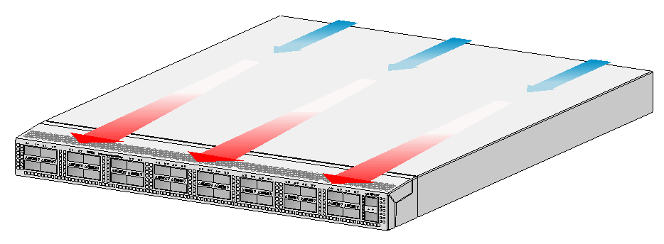
Figure 65 Airflow from the port side to the power module side through the S6820-32H chassis (with LSWM1FANSAB fan trays)
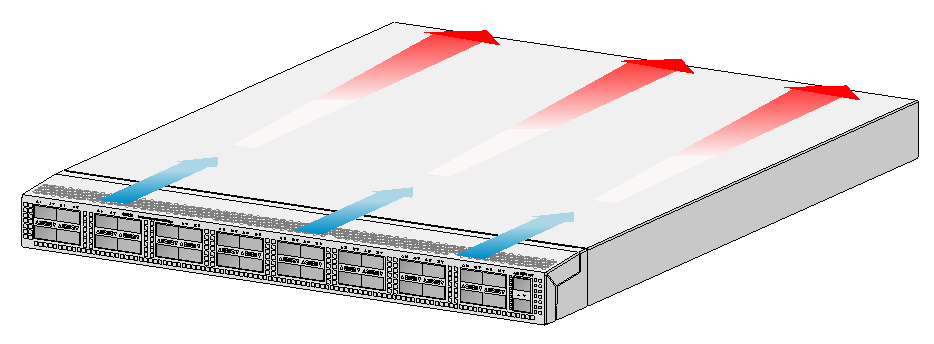
Figure 66 Airflow from the power module side to the port side through the S6820-56HF chassis (with LSWM1FANSA fan trays)
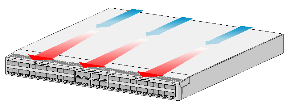
Figure 67 Airflow from the port side to the power module side through the S6820-56HF chassis (with LSWM1FANSAB fan trays)
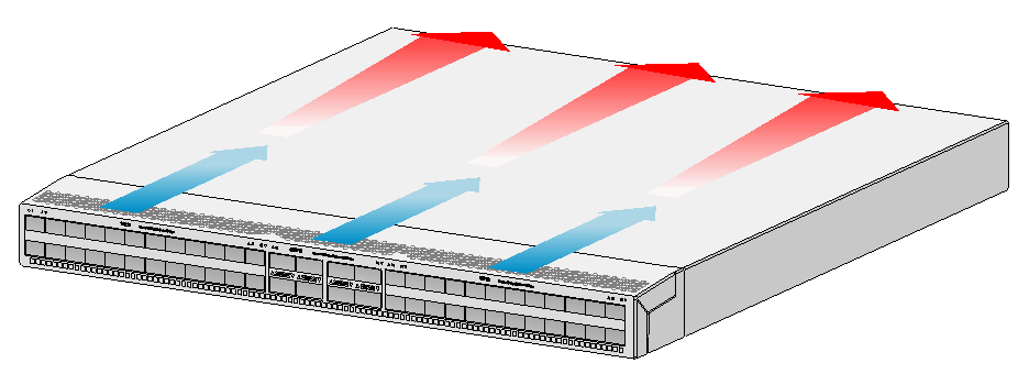
Figure 68 Airflow from the power module side to the port side through the S6820-4C chassis (with LSWM1BFANSC fan trays)
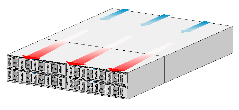
Figure 69 Airflow from the port side to the power module side through the S6820-4C chassis (with LSWM1BFANSCB fan trays)
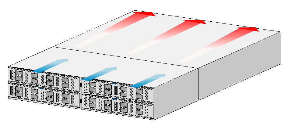
Attaching the mounting brackets and chassis rails to the chassis,10
Attaching the slide rails to the rack,15
Cleanliness,2
Connecting a DC power cord,24
Connecting an AC power cord,24
Connecting the grounding cable to the chassis,14
Console port,50
EMI,2
Fan tray alarm LEDs,60
FE SFP modules,51
Garbled display,40
Identifying physical IRF ports on the member switches,36
Identifying the master switch and planning IRF member IDs,34
Installation accessories,5
Installing a fan tray,19
Installing a power module,21
Installing/removing expansion cards,25
Laser safety,3
Management Ethernet port,50
Management Ethernet port LEDs,59
Mounting brackets, chassis rails, and grounding cable installation positions,7
Mounting the switch in the rack,16
No display,40
Planning IRF fabric size and the installation site,34
Planning IRF topology and connections,34
Planning the cabling scheme,36
QSFP+ port,56
QSFP28 port,53
QSFP28 port LED,58
Rack-mounting procedures at a glance,9
Removing a fan tray,20
Removing a power module,22
S6820-32H,41
S6820-4C,44
S6820-56HF,42
SFP port,53
SFP port LED,59
SFP+ port,51
SFP+ port LED,59
SFP28 port,56
SFP28 port LED,58
Solution,39
Solution,39
Symptom,39
Symptom,39
System status LED,58
Temperature/humidity,1
USB port,51