- Table of Contents
- Related Documents
-
| Title | Size | Download |
|---|---|---|
| 01-Text | 756.35 KB |
Feature and hardware compatibility
VXLAN tunnel establishment and assignment
Assignment of traffic to VXLANs
Configuring basic VXLAN features
Command and hardware compatibility
Assigning a VXLAN tunnel to a VXLAN
Mapping a Layer 3 interface to a VSI
Configuring static remote-MAC address entries
Disabling remote-MAC address learning
Confining unknown-unicast floods to the local site
Setting the destination UDP port number of VXLAN packets
Configuring VXLAN packet check
Enabling ARP flood suppression
Displaying and maintaining VXLANs
Unicast-mode VXLAN configuration example
VXLAN IP gateways separated from VTEPs
Centralized VXLAN IP gateway deployment
Centralized VXLAN gateway group deployment
Distributed VXLAN IP gateway deployment
Command and hardware compatibility
Configuring a centralized VXLAN IP gateway
Configuring a centralized VXLAN IP gateway group
Specifying a VTEP group as the gateway for an access layer VTEP
Configuring a distributed VXLAN IP gateway
Disabling remote ARP learning for VXLANs
Displaying and maintaining VXLAN IP gateway
VXLAN IP gateway configuration examples
Centralized VXLAN IP gateway configuration example
Distributed VXLAN IPv4 gateway configuration example
Distributed VXLAN IPv6 gateway configuration example
Configuration restrictions and guidelines
Configuring the VTEP as an ENDS
Configuring the VTEP as an ENDC
Displaying and maintaining ENDP
Command and hardware compatibility
VXLAN IS-IS configuration task list
Specifying a reserved VXLAN for VXLAN IS-IS
Enabling VXLAN autonegotiation to automate VXLAN tunnel assignment
Enabling MAC advertisement through VXLAN IS-IS
Enabling host route advertisement through VXLAN IS-IS
Enabling local-host route proxy
Enabling host route MAC learning
Configuring the DED priority and CSNP interval
Enabling adjacency change logging
Configuring Graceful Restart for VXLAN IS-IS
Increasing the maximum number of MAC entries in an LSP
Displaying and maintaining VXLAN IS-IS
VXLAN IS-IS configuration example
VXLAN overview
Virtual eXtensible LAN (VXLAN) is a MAC-in-UDP technology that provides Layer 2 connectivity between distant network sites across an IP network. VXLAN is typically used in data centers for multitenant services.
VXLAN provides the following benefits:
· Support for more virtual switched domains than VLANs—Each VXLAN is uniquely identified by a 24-bit VXLAN ID. The total number of VXLANs can reach 16777216 (224). This specification makes VXLAN a better choice than 802.1Q VLAN to isolate traffic for VMs.
· Easy deployment and maintenance—VXLAN requires deployment only on the edge devices of the transport network. Devices in the transport network perform typical Layer 3 forwarding.
The device supports only IPv4-based VXLAN. IPv6-based VXLAN is not supported.
Feature and hardware compatibility
|
Hardware |
VXLAN compatibility |
|
MSR810/810-W/810-W-DB/810-LM/810-W-LM/810-10-PoE/810-LM-HK/810-W-LM-HK |
Yes |
|
MSR810-LMS/810-LUS |
No |
|
MSR2600-6-X1/2600-10-X1 |
Yes |
|
MSR 2630 |
Yes |
|
MSR3600-28/3600-51 |
Yes |
|
MSR3600-28-SI/3600-51-SI |
No |
|
MSR3610-X1/3610-X1-DP/3610-X1-DC/3610-X1-DP-DC |
Yes |
|
MSR 3610/3620/3620-DP/3640/3660 |
Yes |
|
MSR5620/5660/5680 |
Yes |
|
Hardware |
VXLAN compatibility |
|
MSR810-LM-GL |
Yes |
|
MSR810-W-LM-GL |
Yes |
|
MSR830-6EI-GL |
Yes |
|
MSR830-10EI-GL |
Yes |
|
MSR830-6HI-GL |
Yes |
|
MSR830-10HI-GL |
Yes |
|
MSR2600-6-X1-GL |
Yes |
|
MSR3600-28-SI-GL |
No |
VXLAN network model
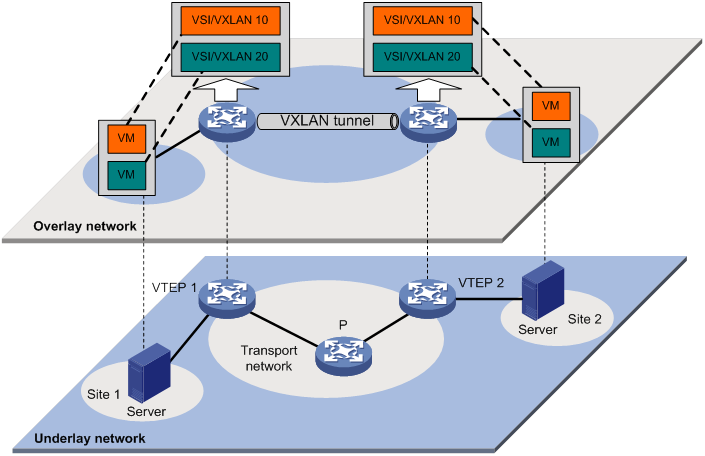
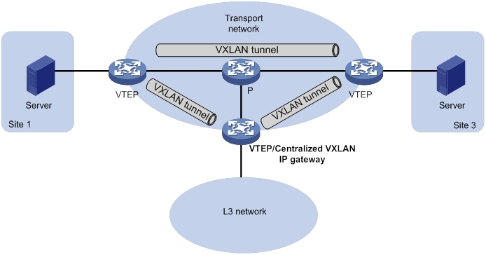
As shown in Figure 1, a VXLAN is a virtual Layer 2 network (known as the overlay network) built on top of an existing physical Layer 3 network (known as the underlay network). The overlay network encapsulates inter-site Layer 2 frames into VXLAN packets and forwards the packets to the destination along the Layer 3 forwarding paths provided by the underlay network. The underlay network is transparent to tenants, and geographically dispersed sites of a tenant are merged into a Layer 2 network.
The transport edge devices assign VMs to different VXLANs, and then forward traffic between sites for VMs by using VXLAN tunnels.
The transport edge devices are VXLAN tunnel endpoints (VTEP). They can be servers that host VMs or independent network devices.
An H3C VTEP uses VSIs and VXLAN tunnels to provide VXLAN services.
· VSI—A virtual switch instance is a virtual Layer 2 switched domain. Each VSI provides switching services only for one VXLAN. VSIs learn MAC addresses and forward frames independently of one another. VMs in different sites have Layer 2 connectivity if they are in the same VXLAN.
· VXLAN tunnel—Logical point-to-point tunnels between VTEPs over the transport network. Each VXLAN tunnel can trunk multiple VXLANs.
VTEPs encapsulate VXLAN traffic in the VXLAN, outer UDP, and outer IP headers. The devices in the transport network forward VXLAN traffic only based on the outer IP header.
Figure 1 VXLAN network model
VXLAN packet format
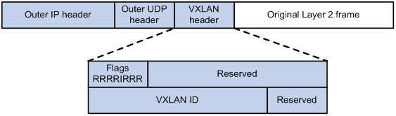
As shown in Figure 2, a VTEP encapsulates a frame in the following headers:
· 8-byte VXLAN header—VXLAN information for the frame.
? Flags—If the I bit is 1, the VXLAN ID is valid. If the I bit is 0, the VXLAN ID is invalid. All other bits are reserved and set to 0.
? 24-bit VXLAN ID—Identifies the VXLAN of the frame. It is also called the virtual network identifier (VNI).
· 8-byte outer UDP header for VXLAN—The default VXLAN destination UDP port number is 4789.
· 20-byte outer IP header—Valid addresses of VTEPs on the transport network. Devices in the transport network forward VXLAN packets based on the outer IP header.
Figure 2 VXLAN packet format
Working mechanisms
The VTEP uses the following process to forward an inter-site frame:
1. Discovers remote VTEPs, establishes VXLAN tunnels, and assigns the VXLAN tunnels to VXLANs.
2. Assigns the frame to its matching VXLAN if the frame is sent between sites.
3. Performs MAC learning on the VXLAN's VSI.
4. Forwards the frame through VXLAN tunnels.
This section describes this process in detail. For intra-site frames in a VSI, the system performs typical Layer 2 forwarding.
VXLAN tunnel establishment and assignment
To provide Layer 2 connectivity for a VXLAN between two sites, you must create a VXLAN tunnel between the sites and assign the tunnel to the VXLAN.
VXLAN tunnel establishment
VXLAN supports manual and automatic VXLAN tunnel establishment.
· Manual creation—Manually create a VXLAN tunnel interface, and specify the tunnel source and destination IP addresses on the peer VTEPs.
· Automatic creation—Configure the Enhanced Neighbor Discovery Protocol (ENDP) or Ethernet Virtual Private Network (EVPN) to automatically discover VTEPs and set up VXLAN tunnels. For more information about ENDP, see "Configuring ENDP." For more information about EVPN, see EVPN Configuration Guide.
VXLAN tunnel assignment
VXLAN supports manual and automatic VXLAN tunnel assignment.
· Manual assignment—Manually assign VXLAN tunnels to VXLANs.
· Automatic assignment—Run VXLAN IS-IS or EVPN to automatically assign VXLAN tunnels to VXLANs. For more information about VXLAN IS-IS, see "Configuring VXLAN IS-IS." For more information about EVPN, see EVPN Configuration Guide.
Assignment of traffic to VXLANs
Traffic from the local site to a remote site
The VTEP uses a Layer 3 interface to match customer traffic. The VTEP assigns customer traffic to a VXLAN by mapping the Layer 3 interface to a VSI. A Layer 3 interface is identical to an attachment circuit (AC) in L2VPN.
Traffic from a remote site to the local site
When a frame arrives at a VXLAN tunnel, the VTEP uses the VXLAN ID in the frame to identify its VXLAN.
MAC learning
The VTEP performs source MAC learning on the VSI as a Layer 2 switch.
· For traffic from the local site to the remote site, the VTEP learns the source MAC address before VXLAN encapsulation.
· For traffic from the remote site to the local site, the VTEP learns the source MAC address after removing the VXLAN header.
A VSI's MAC address table includes the following types of MAC address entries:
· Local MAC—Dynamic MAC entries learned from the local site. The outgoing interfaces are site-facing interfaces on which the MAC addresses are learned. VXLAN does not support manual local-MAC entries.
· Remote MAC—MAC entries learned from a remote site. The outgoing interfaces for the MAC addresses are VXLAN tunnel interfaces.
? Static—Manually added MAC entries.
? Dynamic—MAC entries learned in the data plane from incoming traffic on VXLAN tunnels. The learned MAC addresses are contained in the inner Ethernet header.
? IS-IS—MAC entries advertised through VXLAN IS-IS.
? EVPN—MAC entries advertised through BGP EVPN.
? OpenFlow—MAC entries issued by a remote controller through OpenFlow.
The following shows the priority order of different types of remote MAC address entries:
a. Static MAC address entries and MAC address entries issued by a remote controller through OpenFlow. These types of entries have the same priority and overwrite each other.
b. MAC address entries advertised through VXLAN IS-IS or BGP EVPN. The two types of entries have the same priority and overwrite each other.
c. Dynamic MAC address entries.
Traffic forwarding
A VTEP uses the following processes to forward traffic at Layer 2:
· Unicast process—Applies to destination-known unicast traffic.
· Flood process—Applies to multicast, broadcast, and unknown unicast traffic.
Unicast
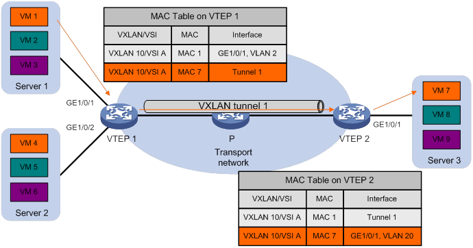
The following process (see Figure 3) applies to a known unicast frame between sites:
1. The source VTEP encapsulates the Ethernet frame in the VXLAN/UDP/IP header.
In the outer IP header, the source IP address is the source VTEP's VXLAN tunnel source IP address. The destination IP address is the VXLAN tunnel destination IP address.
2. The source VTEP forwards the encapsulated packet out of the outgoing VXLAN tunnel interface found in the VSI's MAC address table.
3. The intermediate transport devices (P devices) forward the frame to the destination VTEP by using the outer IP header.
4. The destination VTEP removes the headers on top of the inner Ethernet frame. It then performs MAC address table lookup in the VXLAN's VSI to forward the frame out of the matching outgoing interface.
Flood
The VTEP floods a broadcast, multicast, or unknown unicast frame to all site-facing interfaces and VXLAN tunnels in the VXLAN, except for the incoming interface.
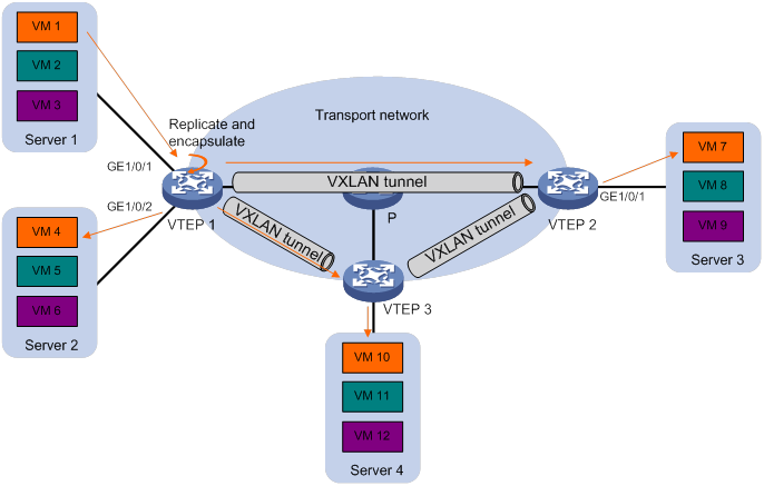
VXLAN supports the following modes for flood traffic:
· Unicast mode—Also called head-end replication. The source VTEP replicates the flood frame, and then sends one replica to the destination IP address of each VXLAN tunnel in the VXLAN. See Figure 4.
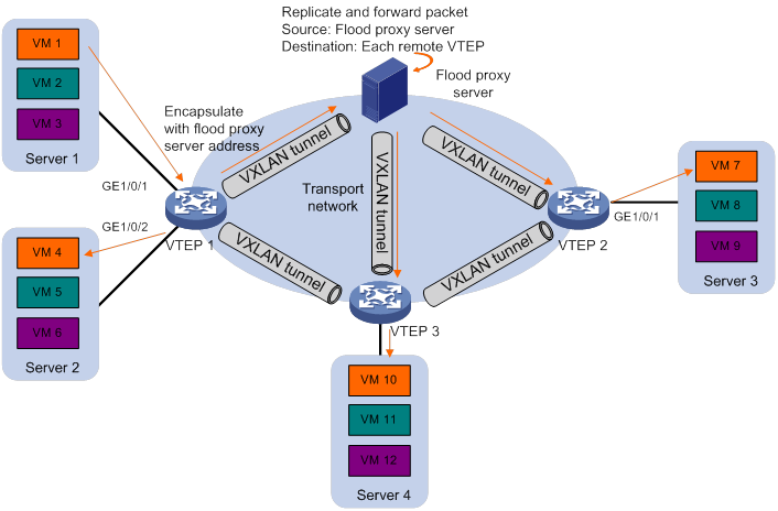
· Flood proxy mode—The source VTEP sends the flood frame in a VXLAN packet over a VXLAN tunnel to a flood proxy server. The flood proxy server replicates and forwards the packet to each remote VTEP through its VXLAN tunnels. See Figure 5.
The flood proxy mode applies to VXLANs that have many sites. To use a flood proxy server, you must set up a VXLAN tunnel to the server on each VTEP.
|
|
NOTE: The flood proxy mode is typically used in SDN transport networks that have a flood proxy server. For VTEPs to forward packets based on the MAC address table issued by an SDN controller, you must disable remote-MAC address learning by using the vxlan tunnel mac-learning disable command. |
Each destination VTEP floods the inner Ethernet frame to all the site-facing interfaces in the VXLAN. To avoid loops, the destination VTEPs do not flood the frame to VXLAN tunnels.
ARP flood suppression
ARP flood suppression reduces ARP request broadcasts by enabling the VTEP to reply to ARP requests on behalf of VMs.
As shown in Figure 6, this feature snoops ARP packets to populate the ARP flood suppression table with local and remote MAC addresses. If an ARP request has a matching entry, the VTEP replies to the request on behalf of the VM. If no match is found, the VTEP floods the request to both local and remote sites.
Figure 6 ARP flood suppression
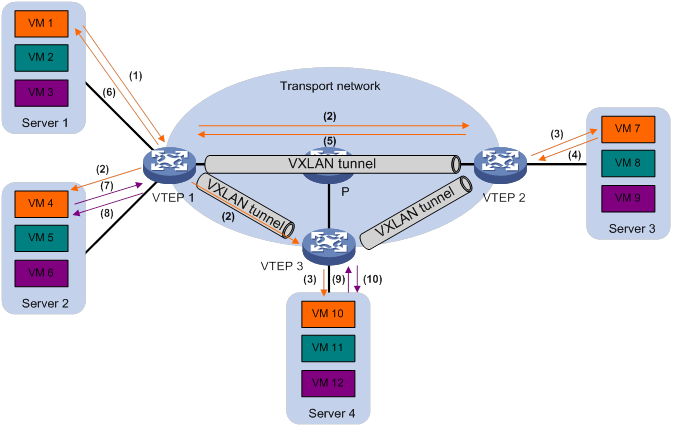
ARP flood suppression uses the following workflow:
1. VM 1 sends an ARP request to obtain the MAC address of VM 7.
2. VTEP 1 creates a suppression entry for VM 1, and floods the ARP request in the VXLAN.
3. VTEP 2 and VTEP 3 de-encapsulate the ARP request. The VTEPs create a suppression entry for VM 1, and broadcast the request in the local site.
4. VM 7 sends an ARP reply.
5. VTEP 2 creates a suppression entry for VM 7 and forwards the ARP reply to VTEP 1.
6. VTEP 1 de-encapsulates the ARP reply, creates a suppression entry for VM 7, and forwards the ARP reply to VM 1.
7. VM 4 sends an ARP request to obtain the MAC address of VM 1 or VM 7.
8. VTEP 1 creates a suppression entry for VM 4 and replies to the ARP request.
9. VM 10 sends an ARP request to obtain the MAC address of VM 1.
10. VTEP 3 creates a suppression entry for VM 10 and replies to the ARP request.
VXLAN IP gateways
A VXLAN IP gateway provides Layer 3 forwarding services for VMs in VXLANs. A VXLAN IP gateway can be an independent device or be collocated with a VTEP. For more information about VXLAN IP gateway placement, see "Configuring VXLAN IP gateways."
Protocols and standards
RFC 7348, Virtual eXtensible Local Area Network (VXLAN): A Framework for Overlaying Virtualized Layer 2 Networks over Layer 3 Networks
Configuring basic VXLAN features
Command and hardware compatibility
Commands and descriptions for centralized devices apply to the following routers:
· MSR810/810-W/810-W-DB/810-LM/810-W-LM/810-10-PoE/810-LM-HK/810-W-LM-HK/ 810-LMS/810-LUS.
· MSR2600-6-X1/2600-10-X1.
· MSR 2630.
· MSR3600-28/3600-51.
· MSR3600-28-SI/3600-51-SI.
· MSR3610-X1/3610-X1-DP/3610-X1-DC/3610-X1-DP-DC.
· MSR 3610/3620/3620-DP/3640/3660.
· MSR810-LM-GL/810-W-LM-GL/830-6EI-GL/830-10EI-GL/830-6HI-GL/830-10HI-GL/2600-6-X1-GL/3600-28-SI-GL.
Commands and descriptions for distributed devices apply to the following routers:
· MSR5620.
· MSR 5660.
· MSR 5680.
VXLAN configuration task list
|
Tasks at a glance |
Remarks |
|
(Required.) Creating a VXLAN on a VSI |
N/A |
|
(Required.) Configuring a VXLAN tunnel |
N/A |
|
(Required.) Assigning a VXLAN tunnel to a VXLAN |
To extend a VXLAN to remote sites, you must assign VXLAN tunnels to the VXLAN. |
|
(Required.) Mapping a Layer 3 interface to a VSI |
Perform this task to assign customer traffic to VXLANs. |
|
(Optional.) Managing MAC address entries |
N/A |
|
(Optional.) Confining unknown-unicast floods to the local site |
N/A |
|
(Optional.) Setting the destination UDP port number of VXLAN packets |
N/A |
|
(Optional.) Configuring VXLAN packet check |
Perform this task to check incoming VXLAN packets, including the following items: · UDP checksum. · 802.1Q VLAN tags in the inner Ethernet header. |
|
(Optional.) Enabling ARP flood suppression |
N/A |
Creating a VXLAN on a VSI
|
Step |
Command |
Remarks |
|
1. Enter system view. |
system-view |
N/A |
|
2. Enable L2VPN. |
l2vpn enable |
By default, L2VPN is disabled. |
|
3. Create a VSI and enter VSI view. |
vsi vsi-name |
By default, no VSIs exist. |
|
4. (Optional.) Configure a VSI description. |
description text |
By default, a VSI does not have a description. |
|
5. Enable the VSI. |
undo shutdown |
By default, a VSI is enabled. |
|
6. (Optional.) Set the MTU for the VSI. |
mtu mtu |
The default MTU is 1500 bytes for a VSI. The MTU set by using this command limits the maximum length of the packets that a VSI receives from ACs and forwards through VXLAN tunnels. The MTU does not limit the maximum length of other packets in the VXLAN VSI. |
|
7. (Optional.) Set the maximum bandwidth for known unicast traffic of the VSI. |
bandwidth bandwidth |
By default, the maximum bandwidth is not limited for known unicast traffic of a VSI. |
|
8. (Optional.) Enable MAC address learning for the VSI. |
mac-learning enable |
By default, MAC address learning is enabled for a VSI. |
|
9. Create a VXLAN and enter VXLAN view. |
vxlan vxlan-id |
By default, no VXLANs exist. You can create only one VXLAN on a VSI. The VXLAN ID must be unique for each VSI. |
Configuring a VXLAN tunnel
You can manually configure a VXLAN tunnel or configure ENDP to automatically establish a VXLAN tunnel. This section describes manual VXLAN tunnel setup. For more information about ENDP, see "Configuring ENDP."
This task provides basic VXLAN tunnel configuration. For more information about tunnel configuration and commands, see Layer 3—IP Services Configuration Guide and Layer 3—IP Services Command Reference.
To configure a VXLAN tunnel:
|
Step |
Command |
Remarks |
|
1. Enter system view. |
system-view |
N/A |
|
2. Create a VXLAN tunnel interface and enter tunnel interface view. |
interface tunnel tunnel-number mode vxlan |
By default, no tunnel interfaces exist. The endpoints of a tunnel must use the same tunnel mode. |
|
3. Specify a source IP address or source interface for the tunnel. |
source { ipv4-address | interface-type interface-number } |
By default, no source IP address or source interface is specified for a tunnel. This step specifies the source IP address in the outer IP header of tunneled VXLAN packets. If an interface is specified, its primary IP address is used. |
|
4. Specify a destination IP address for the tunnel. |
destination ipv4-address |
By default, no destination IP address is specified for a tunnel. Specify the remote VTEP's IP address. This IP address will be the destination IP address in the outer IP header of tunneled VXLAN packets. As a best practice, do not configure multiple VXLAN tunnels to use the same source and destination IP addresses. |
Assigning a VXLAN tunnel to a VXLAN
To provide Layer 2 connectivity for a VXLAN between two sites, you must assign the VXLAN tunnel between the sites to the VXLAN.
You can assign a maximum of 32 VXLAN tunnels to a VXLAN, and configure a VXLAN tunnel to trunk multiple VXLANs. For a unicast-mode VXLAN, the system floods unknown unicast, multicast, and broadcast traffic to each tunnel associated with the VXLAN. If a flood proxy server is used, the VTEP sends flood traffic to the server through the flood proxy tunnel. The flood proxy server replicates and forwards flood traffic to remote VTEPs.
This section describes the manual VXLAN tunnel assignment. For information about automatic VXLAN tunnel assignment through VXLAN IS-IS, see "Configuring VXLAN IS-IS."
To assign a VXLAN tunnel to a VXLAN:
|
Step |
Command |
Remarks |
|
1. Enter system view. |
system-view |
N/A |
|
2. Enter VSI view. |
vsi vsi-name |
N/A |
|
3. Enter VXLAN view. |
vxlan vxlan-id |
N/A |
|
4. Assign a VXLAN tunnel to the VXLAN. |
tunnel tunnel-number [ flooding-proxy ] |
By default, a VXLAN does not contain any VXLAN tunnels. For full Layer 2 connectivity in the VXLAN, make sure the VXLAN contains the VXLAN tunnel between each pair of sites in the VXLAN. Enable flood proxy on the tunnel for the VTEP to send flood traffic to the flood proxy server. The flood proxy server replicates and forwards flood traffic to remote VTEPs. |
Mapping a Layer 3 interface to a VSI
To assign the customer traffic on a Layer 3 interface to a VXLAN, map the interface to the VXLAN's VSI. The VSI uses its MAC address table to forward the customer traffic.
To map a Layer 3 interface to a VSI:
|
Step |
Command |
Remarks |
|
1. Enter system view. |
system-view |
N/A |
|
2. Enter Layer 3 interface view. |
interface interface-type interface-number |
N/A |
|
3. Configure the VLAN tag processing rule for incoming traffic. |
l2vpn rewrite inbound tag { nest { c-vid vlan-id | s-vid vlan-id [ c-vid vlan-id ] } | remark 1-to-2 s-vid vlan-id c-vid vlan-id } [ symmetric ] |
By default, VLAN tags of incoming traffic are not processed. |
|
4. Map the Layer 3 interface to a VSI. |
xconnect vsi vsi-name [ track track-entry-number&<1-3> ] |
By default, a Layer 3 interface is not mapped to any VSI. |
Managing MAC address entries
With VXLAN, local MAC addresses are learned dynamically. You can log MAC changes, but you cannot manually add local MAC addresses.
Remote-MAC address entries include the following types:
· Manually created static entries.
· Dynamic entries learned in the data plane.
· Entries advertised in the control plane through VXLAN IS-IS or EVPN.
· Entries issued by a remote controller through OpenFlow.
For more information about VXLAN IS-IS MAC address advertisement, see "Configuring VXLAN IS-IS." For more information about EVPN, see EVPN Configuration Guide.
Enabling local-MAC logging
When the local-MAC logging feature is enabled, the VXLAN module immediately sends a log message with its local MAC addresses to the information center. When a local MAC address is added or removed, a log message is also sent to the information center to notify the local-MAC change.
With the information center, you can set log message filtering and output rules, including output destinations. For more information about configuring the information center, see Network Management and Monitoring Configuration Guide.
To enable local-MAC logging:
|
Step |
Command |
Remarks |
|
1. Enter system view. |
system-view |
N/A |
|
2. Enable local-MAC logging. |
vxlan local-mac report |
By default, local-MAC logging is disabled. |
Configuring static remote-MAC address entries
Do not configure static remote-MAC entries for VXLAN tunnels that are automatically established by using ENDP or EVPN.
· ENDP or EVPN re-establishes VXLAN tunnels if the transport-facing interface goes down and then comes up. If you have configured static remote-MAC entries, the entries are deleted when the tunnels are re-established.
· ENDP or EVPN re-establishes VXLAN tunnels if you perform configuration rollback. If the tunnel IDs change during tunnel re-establishment, configuration rollback fails, and static remote-MAC entries on the tunnels cannot be restored.
For more information about ENDP, see "Configuring ENDP." For more information about EVPN, see EVPN Configuration Guide.
Configuration rollback fails if the following conditions exist:
· Static remote-MAC entries are configured for manually created VXLAN tunnels.
· Automatic VXLAN tunnel assignment is in progress.
To avoid rollback failure, perform configuration rollback after VXLAN IS-IS finishes VXLAN tunnel assignment. For more information about VXLAN IS-IS, see "Configuring VXLAN IS-IS." For more information about configuration rollback, see configuration file management in Fundamentals Configuration Guide.
To configure static remote-MAC address entries:
|
Step |
Command |
Remarks |
|
1. Enter system view. |
system-view |
N/A |
|
2. Add a static remote entry. |
mac-address static mac-address interface tunnel tunnel-number vsi vsi-name |
By default, VXLAN VSIs do not have static remote-MAC address entries. For the setting to take effect, make sure the VSI's VXLAN has been created and specified on the VXLAN tunnel. |
Disabling remote-MAC address learning
|
Step |
Command |
Remarks |
|
1. Enter system view. |
system-view |
N/A |
|
2. Disable remote-MAC address learning. |
vxlan tunnel mac-learning disable |
By default, remote-MAC address learning is enabled. When network attacks occur, disable remote-MAC address learning to prevent the device from learning incorrect remote MAC addresses. You can manually add static remote-MAC address entries. |
Confining unknown-unicast floods to the local site
By default, the VTEP floods unknown unicast frames received from the local site to the following interfaces in the frame's VXLAN:
· All site-facing interfaces except for the incoming interface.
· All VXLAN tunnel interfaces.
To confine unknown-unicast floods to site-facing interfaces for a VXLAN:
|
Step |
Command |
Remarks |
|
|
1. Enter system view. |
system-view |
N/A |
|
|
2. Enter VSI view. |
vsi vsi-name |
N/A |
|
|
3. Disable the VSI to flood unknown unicast traffic to VXLAN tunnel interfaces. |
flooding disable |
By default, unknown unicast traffic is flooded to all interfaces in the VXLAN, except for the incoming interface. |
|
|
4. (Optional.) Enable selective flood for a MAC address. |
selective-flooding mac-address mac-address |
By default, selective flood is disabled. Use this feature to exclude a remote MAC address from the flood suppression done by using the flooding disable command. The VTEP will flood the frames destined for the specified MAC address to remote sites when unknown-unicast floods are confined to the local site. |
|
Setting the destination UDP port number of VXLAN packets
|
Step |
Command |
Remarks |
|
|
1. Enter system view. |
system-view |
N/A |
|
|
2. Set a destination UDP port for VXLAN packets. |
vxlan udp-port port-number |
By default, the destination UDP port number is 4789 for VXLAN packets. You must configure the same destination UDP port number on all VTEPs in a VXLAN. |
|
Configuring VXLAN packet check
The device can check the UDP checksum and 802.1Q VLAN tags of each received VXLAN packet.
· UDP checksum check—The device always sets the UDP checksum of VXLAN packets to zero. For compatibility with third-party devices, a VXLAN packet can pass the check if its UDP checksum is zero or correct. If its UDP checksum is incorrect, the VXLAN packet fails the check and is dropped.
· VLAN tag check—The device checks the inner Ethernet header of each VXLAN packet for 802.1Q VLAN tags. If the header contains 802.1Q VLAN tags, the device drops the packet.
To configure VXLAN packet check:
|
Step |
Command |
Remarks |
|
1. Enter system view. |
system-view |
N/A |
|
2. Enable the VTEP to drop VXLAN packets that fail UDP checksum check. |
vxlan invalid-udp-checksum discard |
By default, the VTEP does not check the UDP checksum of VXLAN packets. |
|
3. Enable the VTEP to drop VXLAN packets that have 802.1Q VLAN tags in the inner Ethernet header. |
vxlan invalid-vlan-tag discard |
By default, the VTEP does not check the inner Ethernet header for 802.1Q VLAN tags. |
Enabling ARP flood suppression
Use ARP flood suppression to reduce ARP request broadcasts.
The aging timer is fixed at 25 minutes for ARP flood suppression entries. If the suppression table is full, the VTEP stops learning new entries. For the VTEP to learn new entries, you must wait for old entries to age out, or use the reset arp suppression vsi command to clear the table.
If the flooding disable command is configured, set the MAC aging timer to a higher value than the aging timer for ARP flood suppression entries on all VTEPs. This setting prevents the traffic blackhole that occurs when a MAC address entry ages out before its ARP flood suppression entry ages out.
To set the MAC aging timer, use the mac-address timer command.
When remote ARP learning is disabled for VXLANs, the device does not use ARP flood suppression entries to respond to ARP requests received on VXLAN tunnels.
To enable ARP flood suppression:
|
Step |
Command |
Remarks |
|
1. Enter system view. |
system-view |
N/A |
|
2. Enter VSI view. |
vsi vsi-name |
N/A |
|
3. Enable ARP flood suppression. |
arp suppression enable |
By default, ARP flood suppression is disabled. |
Displaying and maintaining VXLANs
Execute display commands in any view and reset commands in user view.
|
Task |
Command |
|
Display ARP flood suppression entries on VSIs (centralized devices in standalone mode). |
display arp suppression vsi [ name vsi-name ] [ count ] |
|
Display ARP flood suppression entries on VSIs (distributed devices in standalone mode/centralized devices in IRF mode). |
display arp suppression vsi [ name vsi-name ] [ slot slot-number ] [ count ] |
|
Display ARP flood suppression entries on VSIs (distributed devices in IRF mode). |
display arp suppression vsi [ name vsi-name ] [ chassis chassis-number slot slot-number ] [ count ] |
|
Display L2VPN information for Layer 3 interfaces that are mapped to VSIs. |
display l2vpn interface [ vsi vsi-name | interface-type interface-number ] [ verbose ] |
|
Display MAC address entries for VSIs. |
display l2vpn mac-address [ vsi vsi-name ] [ dynamic ] [ count ] |
|
Display information about VSIs. |
display l2vpn vsi [ name vsi-name ] [ verbose ] |
|
Display information about tunnel interfaces. |
display interface [ tunnel [ number ] ] [ brief [ description | down ] ] |
|
Display VXLAN tunnel information for VXLANs. |
display vxlan tunnel [ vxlan vxlan-id ] |
|
Clear ARP flood suppression entries on VSIs. |
reset arp suppression vsi [ name vsi-name ] |
|
Clear dynamic MAC address entries on VSIs. |
reset l2vpn mac-address [ vsi vsi-name ] |
|
|
NOTE: For more information about the display interface tunnel command, see tunneling commands in Layer 3—IP Services Command Reference. |
Unicast-mode VXLAN configuration example
Network requirements
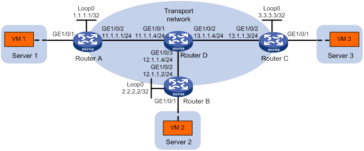
As shown in Figure 7:
· Configure VXLAN 10 as a unicast-mode VXLAN on Router A, Router B, and Router C to provide Layer 2 connectivity for the VMs across the network sites.
· Manually establish VXLAN tunnels and assign the tunnels to VXLAN 10.
· Enable remote-MAC address learning.
Configuration procedure
1. Configure IP addresses and unicast routing settings:
# Assign IP addresses to interfaces, as shown in Figure 7. (Details not shown.)
# Configure OSPF on all transport network routers (Routers A through D). (Details not shown.)
2. Configure Router A:
# Enable L2VPN.
<RouterA> system-view
[RouterA] l2vpn enable
# Create the VSI vpna and VXLAN 10.
[RouterA] vsi vpna
[RouterA-vsi-vpna] vxlan 10
[RouterA-vsi-vpna-vxlan-10] quit
[RouterA-vsi-vpna] quit
# Assign an IP address to Loopback 0. The IP address will be used as the source IP address of the VXLAN tunnels to Router B and Router C.
[RouterA] interface loopback 0
[RouterA-Loopback0] ip address 1.1.1.1 255.255.255.255
[RouterA-Loopback0] quit
# Create a VXLAN tunnel to Router B. The tunnel interface name is Tunnel 1.
[RouterA] interface tunnel 1 mode vxlan
[RouterA-Tunnel1] source 1.1.1.1
[RouterA-Tunnel1] destination 2.2.2.2
[RouterA-Tunnel1] quit
# Create a VXLAN tunnel to Router C. The tunnel interface name is Tunnel 2.
[RouterA] interface tunnel 2 mode vxlan
[RouterA-Tunnel2] source 1.1.1.1
[RouterA-Tunnel2] destination 3.3.3.3
[RouterA-Tunnel2] quit
# Assign Tunnel 1 and Tunnel 2 to VXLAN 10.
[RouterA] vsi vpna
[RouterA-vsi-vpna] vxlan 10
[RouterA-vsi-vpna-vxlan-10] tunnel 1
[RouterA-vsi-vpna-vxlan-10] tunnel 2
[RouterA-vsi-vpna-vxlan-10] quit
[RouterA-vsi-vpna] quit
# Map GigabitEthernet 1/0/1 to the VSI vpna.
[RouterA] interface gigabitethernet 1/0/1
[RouterA-GigabitEthernet1/0/1] xconnect vsi vpna
[RouterA-GigabitEthernet1/0/1] quit
3. Configure Router B:
# Enable L2VPN.
<RouterB> system-view
[RouterB] l2vpn enable
# Create the VSI vpna and VXLAN 10.
[RouterB] vsi vpna
[RouterB-vsi-vpna] vxlan 10
[RouterB-vsi-vpna-vxlan-10] quit
[RouterB-vsi-vpna] quit
# Assign an IP address to Loopback 0. The IP address will be used as the source IP address of the VXLAN tunnels to Router A and Router C.
[RouterB] interface loopback 0
[RouterB-Loopback0] ip address 2.2.2.2 255.255.255.255
[RouterB-Loopback0] quit
# Create a VXLAN tunnel to Router A. The tunnel interface name is Tunnel 2.
[RouterB] interface tunnel 2 mode vxlan
[RouterB-Tunnel2] source 2.2.2.2
[RouterB-Tunnel2] destination 1.1.1.1
[RouterB-Tunnel2] quit
# Create a VXLAN tunnel to Router C. The tunnel interface name is Tunnel 3.
[RouterB] interface tunnel 3 mode vxlan
[RouterB-Tunnel3] source 2.2.2.2
[RouterB-Tunnel3] destination 3.3.3.3
[RouterB-Tunnel3] quit
# Assign Tunnel 2 and Tunnel 3 to VXLAN 10.
[RouterB] vsi vpna
[RouterB-vsi-vpna] vxlan 10
[RouterB-vsi-vpna-vxlan-10] tunnel 2
[RouterB-vsi-vpna-vxlan-10] tunnel 3
[RouterB-vsi-vpna-vxlan-10] quit
[RouterB-vsi-vpna] quit
# Map GigabitEthernet 1/0/1 to the VSI vpna.
[RouterB] interface gigabitethernet 1/0/1
[RouterB-GigabitEthernet1/0/1] xconnect vsi vpna
[RouterB-GigabitEthernet1/0/1] quit
4. Configure Router C:
# Enable L2VPN.
<RouterC> system-view
[RouterC] l2vpn enable
# Create the VSI vpna and VXLAN 10.
[RouterC] vsi vpna
[RouterC-vsi-vpna] vxlan 10
[RouterC-vsi-vpna-vxlan-10] quit
[RouterC-vsi-vpna] quit
# Assign an IP address to Loopback 0. The IP address will be used as the source IP address of the VXLAN tunnels to Router A and Router B.
[RouterC] interface loopback 0
[RouterC-Loopback0] ip address 3.3.3.3 255.255.255.255
[RouterC-Loopback0] quit
# Create a VXLAN tunnel to Router A. The tunnel interface name is Tunnel 1.
[RouterC] interface tunnel 1 mode vxlan
[RouterC-Tunnel1] source 3.3.3.3
[RouterC-Tunnel1] destination 1.1.1.1
[RouterC-Tunnel1] quit
# Create a VXLAN tunnel to Router B. The tunnel interface name is Tunnel 3.
[RouterC] interface tunnel 3 mode vxlan
[RouterC-Tunnel3] source 3.3.3.3
[RouterC-Tunnel3] destination 2.2.2.2
[RouterC-Tunnel3] quit
# Assign Tunnel 1 and Tunnel 3 to VXLAN 10.
[RouterC] vsi vpna
[RouterC-vsi-vpna] vxlan 10
[RouterC-vsi-vpna-vxlan-10] tunnel 1
[RouterC-vsi-vpna-vxlan-10] tunnel 3
[RouterC-vsi-vpna-vxlan-10] quit
[RouterC-vsi-vpna] quit
# Map GigabitEthernet 1/0/1 to the VSI vpna.
[RouterC] interface gigabitethernet 1/0/1
[RouterC-GigabitEthernet1/0/1] xconnect vsi vpna
[RouterC-GigabitEthernet1/0/1] quit
Verifying the configuration
1. Verify the VXLAN settings on the VTEPs. This example uses Router A.
# Verify that the VXLAN tunnel interfaces on the VTEP are up.
[RouterA] display interface tunnel 1
Tunnel1
Current state: UP
Line protocol state: UP
Description: Tunnel1 Interface
Bandwidth: 64 kbps
Maximum transmission unit: 1464
Internet protocol processing: Disabled
Output queue - Urgent queuing: Size/Length/Discards 0/1024/0
Output queue - Protocol queuing: Size/Length/Discards 0/500/0
Output queue - FIFO queuing: Size/Length/Discards 0/75/0
Last clearing of counters: Never
Tunnel source 1.1.1.1, destination 2.2.2.2
Tunnel protocol/transport UDP_VXLAN/IP
Last 300 seconds input rate: 0 bytes/sec, 0 bits/sec, 0 packets/sec
Last 300 seconds output rate: 0 bytes/sec, 0 bits/sec, 0 packets/sec
Input: 0 packets, 0 bytes, 0 drops
Output: 0 packets, 0 bytes, 0 drops
# Verify that the VXLAN tunnels have been assigned to the VXLAN.
[RouterA] display l2vpn vsi verbose
VSI Name: vpna
VSI Index : 0
VSI State : Up
MTU : 1500
Bandwidth : -
Broadcast Restrain : -
Multicast Restrain : -
Unknown Unicast Restrain: -
MAC Learning : Enabled
MAC Table Limit : -
Mac Learning rate : -
Drop Unknown : -
Flooding : Enabled
VXLAN ID : 10
Tunnels:
Tunnel Name Link ID State Type Flood proxy
Tunnel1 0x5000001 Up Manual Disabled
Tunnel2 0x5000002 Up Manual Disabled
ACs:
AC Link ID State
GE1/0/1 0 Up
# Verify that the VTEP has learned the MAC addresses of remote VMs.
<RouterA> display l2vpn mac-address
MAC Address State VSI Name Link ID/Name Aging
cc3e-5f9c-6cab Dynamic vpna 0 Aging
cc3e-5f9c-6cdb Dynamic vpna Tunnel1 Aging
cc3e-5f9c-23dc Dynamic vpna Tunnel2 Aging
--- 3 mac address(es) found ---
2. Verify that VM 1, VM 2, and VM 3 can ping each other. (Details not shown.)
Configuring VXLAN IP gateways
Overview
The following are available IP gateway placement designs for VXLANs:
· VXLAN IP gateways separated from VTEPs—Use a VXLAN-unaware device as a gateway to the external network for VXLANs. On the gateway, you do not need to configure VXLAN settings.
· VXLAN IP gateways collocated with VTEPs—Include the following placement designs:
? Centralized VXLAN IP gateway deployment—Use one VTEP to provide Layer 3 forwarding for VXLANs. Typically, the gateway-collocated VTEP connects to other VTEPs and the external network. To use this design, make sure the IP gateway has sufficient bandwidth and processing capability. Centralized VXLAN IP gateways provide services only for IPv4 networks.
? Centralized VXLAN gateway group deployment—Use one VTEP group that contains redundant centralized VXLAN IP gateways to provide reliable gateway services for VXLANs.
? Distributed VXLAN IP gateway deployment—Deploy one VXLAN IP gateway on each VTEP to provide Layer 3 forwarding for VXLANs at their respective sites. This design distributes the Layer 3 traffic load across VTEPs. However, its configuration is more complex than the centralized VXLAN IP gateway design. Distributed gateways can provide services for both IPv4 and IPv6 networks.
In a collocation design, the VTEPs use virtual Layer 3 VSI interfaces as gateway interfaces to provide services for VXLANs.
VXLAN IP gateways separated from VTEPs
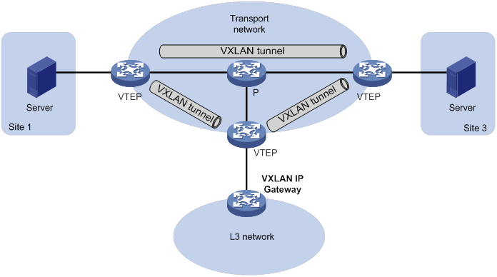
As shown in Figure 8, an independent VXLAN IP gateway connects a Layer 3 network to a VTEP. VMs send Layer 3 traffic in Layer 2 frames to the gateway through VXLAN tunnels. When the tunneled VXLAN packets arrive, the VTEP terminates the VXLANs and forwards the inner frames to the gateway. In this gateway placement design, the VTEP does not perform Layer 3 forwarding for VXLANs.
Figure 8 VXLAN IP gateway separated from VTEPs
Centralized VXLAN IP gateway deployment
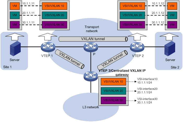
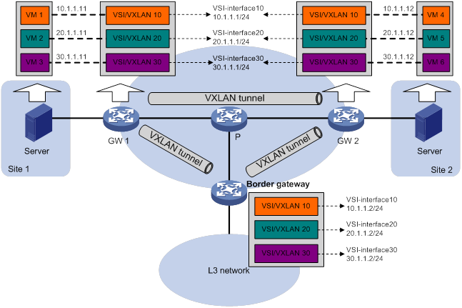
As shown in Figure 9, a VTEP acts as a gateway for VMs in the VXLANs. The VTEP both terminates the VXLANs and performs Layer 3 forwarding for the VMs.
Figure 9 Centralized VXLAN IP gateway placement design
As shown in Figure 10, the network uses the following process to forward Layer 3 traffic from VM 10.1.1.11 to the Layer 3 network:
1. The VM sends an ARP request to obtain the MAC address of the gateway (VTEP 3) at 10.1.1.1.
2. VTEP 1 floods the ARP request to all remote VTEPs.
3. VTEP 3 de-encapsulates the ARP request, creates an ARP entry for the VM, and sends an ARP reply to the VM.
4. VTEP 1 forwards the ARP reply to the VM.
5. The VM learns the MAC address of the gateway, and sends the Layer 3 traffic to the gateway.
6. VTEP 3 removes the VXLAN encapsulation and inner Ethernet header for the traffic, and forwards the traffic to the destination node.
Inter-VXLAN forwarding is the same as this process except for the last step. At the last step of inter-VLAN forwarding, the gateway replaces the source-VXLAN encapsulation with the destination-VXLAN encapsulation, and then forwards the traffic.
Figure 10 Example of centralized VXLAN IP gateway deployment
Centralized VXLAN gateway group deployment
As shown in Figure 11, a VTEP group uses redundant centralized VXLAN IP gateways to provide reliable gateway services for VMs in the VXLANs. All member VTEPs in the group participate in Layer 3 forwarding and load share traffic between the Layer 3 network and the VXLANs. This design distributes intense processing burden among multiple VTEPs and prevents single points of failure.
Figure 11 Example of centralized VXLAN IP gateway group deployment
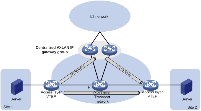
The VTEP group is a virtual gateway that provides services at a group IP address. Access layer VTEPs set up VXLAN tunnels to the group IP address for data traffic forwarding. Each VTEP in the group automatically uses its member IP address to set up tunnels to the other member VTEPs and access layer VTEPs. The tunnels are used to transmit protocol packets and synchronize ARP entries.
Distributed VXLAN IP gateway deployment
As shown in Figure 12, each site's VTEP acts as a gateway to perform Layer 3 forwarding for the VXLANs of the local site. A VTEP acts as a border gateway to the Layer 3 network for the VXLANs. The VTEPs perform Layer 3 forwarding based on ARP or ND entries.
|
|
IMPORTANT: The site-connected gateways are called distributed gateways. On the distributed gateways, you must enable local proxy ARP (for IPv4 sites) or local ND proxy (for IPv6 sites). |
Figure 12 Distributed VXLAN IP gateway placement design
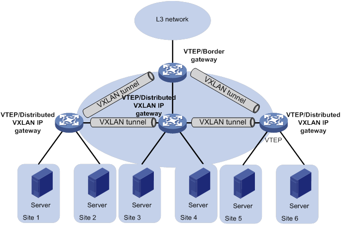
Figure 13 shows an example of distributed VXLAN IP gateway deployment. This section uses this figure to describe the forwarding processes for intra-VXLAN traffic, inter-VXLAN traffic, and traffic from a VXLAN to an external network. In these processes, VTEPs use dynamically learned ARP entries.
Figure 13 Example of distributed VXLAN IP gateway deployment
Intra-VXLAN traffic forwarding between sites
As shown in Figure 13, the network uses the following process to forward traffic in a VXLAN between sites (for example, from VM 1 to VM 4 in VXLAN 10):
1. VM 1 sends an ARP request to obtain the MAC address of VM 4.
2. GW 1 performs the following operations:
a. Creates an ARP entry for VM 1 and replies with the MAC address of VSI-interface 10 (the gateway interface for VXLAN 10).
b. Replaces the sender MAC address of the ARP request with the MAC address of VSI-interface 10, and then floods the request to all remote VTEPs.
3. VM 1 creates an ARP entry for VM 4. The MAC address in the entry is the MAC address of VSI-interface 10 on GW 1.
4. GW 2 (the VTEP for VM 4) performs the following operations:
a. De-encapsulates the ARP request and creates an ARP entry for VM 1. The entry contains VM 1's IP address (10.1.1.11), the MAC address of VSI-interface 10 on GW 1, and the incoming tunnel interface.
b. Replaces the sender MAC address of the request with the MAC address of VSI-interface 10 on GW 2, and then floods the request to the local site in VXLAN 10.
5. VM 4 creates an ARP entry for VM 1, and then sends a reply to GW 2. The MAC address in the ARP entry is the MAC address of VSI-interface 10 on GW 2.
6. GW 2 performs the following operations:
a. Creates an ARP entry for VM 4.
b. Replaces the sender MAC address of the request with the MAC address of VSI-interface 10 on GW 2, and sends the reply to GW 1.
7. GW 1 de-encapsulates the ARP request and creates an ARP entry for VM 4. The entry contains VM 4's IP address (10.1.1.12), the MAC address of VSI-interface 10 on GW 2, and the incoming tunnel interface.
8. For subsequent traffic between VM 1 and VM 4, GW 1 and GW 2 use their respective ARP tables to make the forwarding decision.
Inter-VXLAN traffic forwarding between sites
As shown in Figure 13, the network uses the following process to forward traffic between VXLANs (for example, from VM 1 in VXLAN 10 to VM 5 in VXLAN 20):
1. VM 1 sends an ARP request to obtain the MAC address of the gateway at 10.1.1.1.
2. GW 1 creates an ARP entry for VM 1 and replies with the MAC address of VSI-interface 10 (the gateway interface for VXLAN 10).
3. VM 1 sends the packet destined for VM 5 to GW 1.
4. GW 1 sends an ARP request to the local site and remote sites to obtain the MAC address of VM 5. In the ARP request, the sender IP address is 20.1.1.1, and the sender MAC address is the MAC address of VSI-interface 20 on GW 1.
5. GW 2 performs the following operations:
a. De-encapsulates the ARP request and creates an ARP entry for GW 1. The entry contains IP address 20.1.1.1 and MAC address of VSI-interface 20 on GW 1, and the incoming tunnel interface.
b. Replaces the sender MAC address of the request with the MAC address of VSI-interface 20 on GW 2, and then floods the request to the local site in VXLAN 20.
6. VM 5 creates an ARP entry for GW 2, and then sends a reply to GW 2. The entry contains the IP address (20.1.1.1) and MAC address of VSI-interface 20 on GW 2).
7. GW 2 performs the following operations:
a. Creates an ARP entry for VM 5.
b. Replaces the sender MAC address in the request with the MAC address of VSI-interface 20 on GW 2, and then sends the reply to GW 1.
8. GW 1 de-encapsulates the ARP request and creates an ARP entry for VM 5. The entry contains VM 5's IP address 20.1.1.12, the MAC address of VSI-interface 20 on GW 2, and the incoming tunnel interface.
9. For subsequent traffic between VM 1 and VM 4, GW 1 and GW 2 use their respective ARP tables to make the forwarding decision.
VXLAN-to-external network traffic forwarding
As shown in Figure 13, the network uses the following process to forward traffic from a VXLAN to the Layer 3 network (for example, from VM 1 to the host at 50.1.1.1):
1. VM 1 sends an ARP request to obtain the MAC address of the gateway at 10.1.1.1.
2. GW 1 creates an ARP entry for VM 1 and replies with the MAC address of VSI-interface 10 (the gateway interface for VXLAN 10).
3. VM 1 sends a packet destined for the host to GW 1.
4. GW 1 performs the following operations:
a. Searches the IP routing policies or routing table for the next hop. In this example, the next hop for the packet is 10.1.1.2 (the border gateway).
b. Floods an ARP request to the local and remote sites in VXLAN 10 to obtain the MAC address of 10.1.1.2.
5. The border gateway de-encapsulates the ARP request, creates an ARP entry for GW 1, and tunnels a reply to GW 1.
6. GW 1 de-encapsulates the ARP reply and creates an ARP entry for 10.1.1.2.
7. GW 1 sends the packet destined for the host to the border gateway.
8. The border gateway de-encapsulates the packet and forwards it to the host.
Command and hardware compatibility
IPv6-related parameters are not supported on the following routers:
· MSR810/810-W/810-W-DB/810-LM/810-W-LM/810-10-PoE/810-LM-HK/810-W-LM-HK/ 810-LMS/810-LUS.
· MSR3600-28-SI/3600-51-SI.
Configuration prerequisites
Before you configure a centralized or distributed VXLAN IP gateway, you must perform the following tasks on VTEPs:
· Create VSIs and VXLANs.
· Configure VXLAN tunnels and assign them to VXLANs.
Configuring a centralized VXLAN IP gateway
|
Step |
Command |
Remarks |
|
|
1. Enter system view. |
system-view |
N/A |
|
|
2. Create a VSI interface and enter VSI interface view. |
interface vsi-interface vsi-interface-id |
By default, no VSI interfaces exist. |
|
|
3. Assign an IPv4 address to the VSI interface. |
ip address ip-address { mask | mask-length } |
By default, no IPv4 address is assigned to a VSI interface. |
|
|
4. Return to system view. |
quit |
N/A |
|
|
5. Enter VSI view. |
vsi vsi-name |
N/A |
|
|
6. Specify a gateway interface for the VSI. |
gateway vsi-interface vsi-interface-id |
By default, no gateway interface is specified for a VSI. |
|
Configuring a centralized VXLAN IP gateway group
Configuring a VTEP group
Make sure the member VTEPs use the same VXLAN settings.
Configure a VTEP group on a member VTEP:
|
Step |
Command |
Remarks |
|
1. Enter system view. |
system-view |
N/A |
|
2. Create a VSI interface and enter VSI interface view. |
interface vsi-interface vsi-interface-id |
By default, no VSI interfaces exist. You must create the same VSI interface on all VTEPs in the VTEP group. |
|
3. Assign an IP address to the VSI interface. |
ip address ip-address { mask | mask-length } |
By default, no IP address is assigned to a VSI interface. You must assign the same IP address to the VSI interface on each VTEP in the VTEP group. |
|
4. Assign a MAC address to the VSI interface. |
mac-address mac-address |
By default, no MAC address is assigned to a VSI interface. You must assign the same MAC address to the VSI interface on each VTEP in the VTEP group. |
|
5. Return to system view. |
quit |
N/A |
|
6. Enter VSI view. |
vsi vsi-name |
N/A |
|
7. Specify a gateway interface for the VSI. |
gateway vsi-interface vsi-interface-id |
By default, no gateway interface is specified for a VSI. |
|
8. Return to system view. |
quit |
N/A |
|
9. Assign the local VTEP to a VTEP group and specify the member IP address for the VTEP. |
vtep group group-ip member local member-ip |
By default, a VTEP is not assigned to any VTEP group. Perform this task on all member VTEPs in the VTEP group. The IP address specified by the member-ip argument must already exist on the local VTEP. You must configure a routing protocol to advertise the IP address in the transport network. Member VTEPs in a VTEP group cannot use the group IP address or share an IP address. |
|
10. Specify all the other VTEPs in the VTEP group. |
vtep group group-ip member remote member-ip&<1-8> |
By default, no VTEP group is specified. Perform this task on all member VTEPs in the VTEP group. |
Specifying a VTEP group as the gateway for an access layer VTEP
Before you specify a VTEP group on an access layer VTEP, perform the following tasks on the VTEP:
· Configure VSIs and VXLANs.
· Set up VXLAN tunnels to remote sites and the VTEP group, and assign the tunnels to VXLANs.
To specify a VTEP group as the gateway for an access layer VTEP:
|
Step |
Command |
Remarks |
|
1. Enter system view. |
system-view |
N/A |
|
2. Specify a VTEP group and all its member VTEPs. |
vtep group group-ip member remote member-ip&<1-8> |
By default, no VTEP group is specified. |
Configuring a distributed VXLAN IP gateway
For a VXLAN that requires access to the external network, specify the VXLAN's VSI interface on the border gateway as the next hop by using one of the following methods:
· Configure a static route.
· Configure a routing policy, and apply the policy by using the apply default-next-hop command. For more information about configuring routing policies, see routing policy configuration in Layer 3—IP Routing Configuration Guide.
ARP flood suppression is not supported on distributed VXLAN IP gateways. For more information about ARP flood suppression, see "Enabling ARP flood suppression."
To configure a distributed VXLAN IP gateway:
|
Step |
Command |
Remarks |
|
1. Enter system view. |
system-view |
N/A |
|
2. Create a VSI interface and enter VSI interface view. |
interface vsi-interface vsi-interface-id |
By default, no VSI interfaces exist. |
|
3. Assign an IPv4 or IPv6 address to the VSI interface. |
·
Assign an IPv4 address: ·
Assign an IPv6 address: |
By default, no IPv4 or IPv6 address is assigned to a VSI interface. This interface will be used as a gateway for VXLANs. On an IPv4 network, you can assign one primary IP address and multiple secondary IP addresses. On an IPv6 network, you can assign multiple IPv6 addresses. |
|
4. Specify the VSI interface as a distributed gateway. |
distributed-gateway local |
By default, a VSI interface is not a distributed gateway. |
|
5. Enable local proxy ARP or local ND proxy. |
·
Enable local proxy ARP on an IPv4 gateway: ·
Enable local ND proxy on an IPv6
gateway: |
By default, local proxy ARP and local ND proxy are disabled. For more information about the commands, see Layer 3—IP Services Command Reference. |
|
6. Return to system view. |
quit |
N/A |
|
7. Enter VSI view. |
vsi vsi-name |
N/A |
|
8. Specify the VSI interface as the gateway interface for the VSI. |
gateway vsi-interface vsi-interface-id |
By default, no gateway interface is specified for a VSI. |
|
9. Assign a subnet to the VSI. |
gateway subnet { ipv4-address wildcard-mask | ipv6-address prefix-length } |
By default, no subnet exists on a VSI. You must configure this command on VSIs that share a gateway interface. This command enables the VSI interface to identify the VSI of a packet. You can assign a maximum of eight IPv4 and IPv6 subnets to a VSI. Make sure these subnets are on the same network as one of the IP addresses on the gateway interface. For VSIs that share a gateway interface, the subnets must be unique. If you remove the gateway interface from the VSI, the VSI's subnet settings are automatically deleted. |
Disabling remote ARP learning for VXLANs
By default, the device learns ARP information of remote VMs from packets received on VXLAN tunnel interfaces. To save resources on VTEPs in an SDN transport network, you can temporarily disable remote ARP learning when the controller and VTEPs are synchronizing entries. After the entry synchronization is completed, enable remote ARP learning.
As a best practice, disable remote ARP learning for VXLANs only when the controller and VTEPs are synchronizing entries.
To disable remote ARP learning for VXLANs:
|
Step |
Command |
Remarks |
|
1. Enter system view. |
system-view |
N/A |
|
2. Disable remote ARP learning for VXLANs. |
vxlan tunnel arp-learning disable |
By default, remote ARP learning is enabled for VXLANs. |
Configuring a VSI interface
|
Step |
Command |
Remarks |
|
|
1. Enter system view. |
system-view |
N/A |
|
|
2. Enter VSI interface view. |
interface vsi-interface vsi-interface-id |
N/A |
|
|
3. (Optional.) Assign a MAC address to the VSI interface. |
mac-address mac-address |
By default, no MAC address is assigned to a VSI interface. |
|
|
4. (Optional.) Configure a description for the VSI interface. |
description text |
The default description of a VSI interface is interface-name plus Interface (for example, Vsi-interface100 Interface). |
|
|
5. (Optional.) Set the MTU for the VSI interface. |
mtu size |
The default MTU is 1500 bytes. |
|
|
6. (Optional.) Set the expected bandwidth for the VSI interface. |
bandwidth bandwidth-value |
The default expected bandwidth (in kbps) equals the interface baudrate divided by 1000. |
|
|
7. (Optional.) Apply a QoS policy to the VSI interface. |
qos apply policy policy-name { inbound | outbound } |
By default, no QoS policy is applied to an interface. For more information about this command and QoS policy configuration, see ACL and QoS Configuration Guide. |
|
|
8. Restore the default settings on the interface |
default |
N/A |
|
|
9. Bring up the interface. |
undo shutdown |
By default, a VSI interface is up. |
|
Displaying and maintaining VXLAN IP gateway
Execute display commands in any view and reset commands in user view.
|
Task |
Command |
|
Display information about VSI interfaces. |
display interface [ vsi-interface [ vsi-interface-id ] ] [ brief [ description | down ] ] |
|
Clear statistics on VSI interfaces. |
reset counters interface [ vsi-interface [ vsi-interface-id ] ] |
VXLAN IP gateway configuration examples
Centralized VXLAN IP gateway configuration example
Network requirements
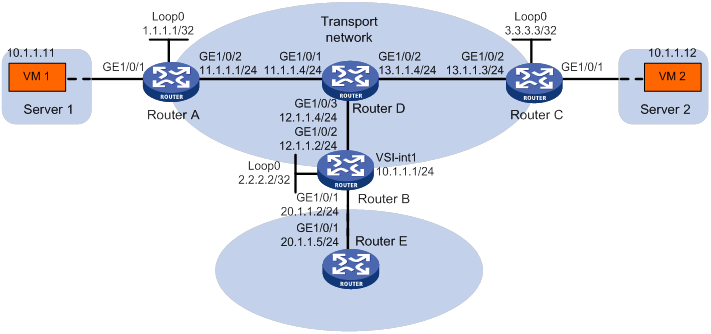
As shown in Figure 14:
· Configure VXLAN 10 as a unicast-mode VXLAN on Router A, Router B, and Router C to provide connectivity for the VMs across the network sites.
· Configure a centralized VXLAN IP gateway on Router B to provide gateway services for VXLAN 10.
· Manually establish VXLAN tunnels and assign the tunnels to VXLAN 10.
· Enable remote-MAC address learning.
Configuration procedure
1. On VM 1 and VM 2, specify 10.1.1.1 as the gateway address. (Details not shown.)
2. Configure IP addresses and unicast routing settings:
# Assign IP addresses to interfaces, as shown in Figure 14. (Details not shown.)
# Configure OSPF on all transport network routers (Routers A through D). (Details not shown.)
# Configure OSPF to advertise routes to networks 10.1.1.0/24 and 20.1.1.0/24 on Router B and Router E. (Details not shown.)
3. Configure Router A:
# Enable L2VPN.
<RouterA> system-view
[RouterA] l2vpn enable
# Create the VSI vpna and VXLAN 10.
[RouterA] vsi vpna
[RouterA-vsi-vpna] vxlan 10
[RouterA-vsi-vpna-vxlan-10] quit
[RouterA-vsi-vpna] quit
# Assign an IP address to Loopback 0. The IP address will be used as the source IP address of the VXLAN tunnels to Router B and Router C.
[RouterA] interface loopback 0
[RouterA-Loopback0] ip address 1.1.1.1 255.255.255.255
[RouterA-Loopback0] quit
# Create a VXLAN tunnel to Router B. The tunnel interface name is Tunnel 1.
[RouterA] interface tunnel 1 mode vxlan
[RouterA-Tunnel1] source 1.1.1.1
[RouterA-Tunnel1] destination 2.2.2.2
[RouterA-Tunnel1] quit
# Create a VXLAN tunnel to Router C. The tunnel interface name is Tunnel 2.
[RouterA] interface tunnel 2 mode vxlan
[RouterA-Tunnel2] source 1.1.1.1
[RouterA-Tunnel2] destination 3.3.3.3
[RouterA-Tunnel2] quit
# Assign Tunnel 1 and Tunnel 2 to VXLAN 10.
[RouterA] vsi vpna
[RouterA-vsi-vpna] vxlan 10
[RouterA-vsi-vpna-vxlan-10] tunnel 1
[RouterA-vsi-vpna-vxlan-10] tunnel 2
[RouterA-vsi-vpna-vxlan-10] quit
[RouterA-vsi-vpna] quit
# Map GigabitEthernet 1/0/1 to the VSI vpna.
[RouterA] interface gigabitethernet 1/0/1
[RouterA-GigabitEthernet1/0/1] xconnect vsi vpna
[RouterA-GigabitEthernet1/0/1] quit
4. Configure Router B:
# Enable L2VPN.
<RouterB> system-view
[RouterB] l2vpn enable
# Create the VSI vpna and VXLAN 10.
[RouterB] vsi vpna
[RouterB-vsi-vpna] vxlan 10
[RouterB-vsi-vpna-vxlan-10] quit
[RouterB-vsi-vpna] quit
# Assign an IP address to Loopback 0. The IP address will be used as the source IP address of the VXLAN tunnels to Router A and Router C.
[RouterB] interface loopback 0
[RouterB-Loopback0] ip address 2.2.2.2 255.255.255.255
[RouterB-Loopback0] quit
# Create a VXLAN tunnel to Router A. The tunnel interface name is Tunnel 2.
[RouterB] interface tunnel 2 mode vxlan
[RouterB-Tunnel2] source 2.2.2.2
[RouterB-Tunnel2] destination 1.1.1.1
[RouterB-Tunnel2] quit
# Create a VXLAN tunnel to Router C. The tunnel interface name is Tunnel 3.
[RouterB] interface tunnel 3 mode vxlan
[RouterB-Tunnel3] source 2.2.2.2
[RouterB-Tunnel3] destination 3.3.3.3
[RouterB-Tunnel3] quit
# Assign Tunnel 2 and Tunnel 3 to VXLAN 10.
[RouterB] vsi vpna
[RouterB-vsi-vpna] vxlan 10
[RouterB-vsi-vpna-vxlan-10] tunnel 2
[RouterB-vsi-vpna-vxlan-10] tunnel 3
[RouterB-vsi-vpna-vxlan-10] quit
[RouterB-vsi-vpna] quit
# Create VSI-interface 1 and assign the interface an IP address. The IP address will be used as the gateway address for VXLAN 10.
[RouterB] interface vsi-interface 1
[RouterB-Vsi-interface1] ip address 10.1.1.1 255.255.255.0
[RouterB-Vsi-interface1] quit
# Specify VSI-interface 1 as the gateway interface for the VSI vpna.
[RouterB] vsi vpna
[RouterB-vsi-vpna] gateway vsi-interface 1
[RouterB-vsi-vpna] quit
5. Configure Router C:
# Enable L2VPN.
<RouterC> system-view
[RouterC] l2vpn enable
# Create the VSI vpna and VXLAN 10.
[RouterC] vsi vpna
[RouterC-vsi-vpna] vxlan 10
[RouterC-vsi-vpna-vxlan-10] quit
[RouterC-vsi-vpna] quit
# Assign an IP address to Loopback 0. The IP address will be used as the source IP address of the VXLAN tunnels to Router A and Router B.
[RouterC] interface loopback 0
[RouterC-Loopback0] ip address 3.3.3.3 255.255.255.255
[RouterC-Loopback0] quit
# Create a VXLAN tunnel to Router A. The tunnel interface name is Tunnel 1.
[RouterC] interface tunnel 1 mode vxlan
[RouterC-Tunnel1] source 3.3.3.3
[RouterC-Tunnel1] destination 1.1.1.1
[RouterC-Tunnel1] quit
# Create a VXLAN tunnel to Router B. The tunnel interface name is Tunnel 3.
[RouterC] interface tunnel 3 mode vxlan
[RouterC-Tunnel3] source 3.3.3.3
[RouterC-Tunnel3] destination 2.2.2.2
[RouterC-Tunnel3] quit
# Assign Tunnel 1 and Tunnel 3 to VXLAN 10.
[RouterC] vsi vpna
[RouterC-vsi-vpna] vxlan 10
[RouterC-vsi-vpna-vxlan-10] tunnel 1
[RouterC-vsi-vpna-vxlan-10] tunnel 3
[RouterC-vsi-vpna-vxlan-10] quit
[RouterC-vsi-vpna] quit
# Map GigabitEthernet 1/0/1 to the VSI vpna.
[RouterC] interface gigabitethernet 1/0/1
[RouterC-GigabitEthernet1/0/1] xconnect vsi vpna
[RouterC-GigabitEthernet1/0/1] quit
Verifying the configuration
1. Verify the VXLAN IP gateway settings on Router B:
# Verify that the VXLAN tunnel interfaces are up on Router B.
[RouterB] display interface tunnel 2
Tunnel2
Current state: UP
Line protocol state: UP
Description: Tunnel2 Interface
Bandwidth: 64 kbps
Maximum transmission unit: 1464
Internet protocol processing: Disabled
Output queue - Urgent queuing: Size/Length/Discards 0/1024/0
Output queue - Protocol queuing: Size/Length/Discards 0/500/0
Output queue - FIFO queuing: Size/Length/Discards 0/75/0
Last clearing of counters: Never
Tunnel source 2.2.2.2, destination 1.1.1.1
Tunnel protocol/transport UDP_VXLAN/IP
Last 300 seconds input rate: 0 bytes/sec, 0 bits/sec, 0 packets/sec
Last 300 seconds output rate: 0 bytes/sec, 0 bits/sec, 0 packets/sec
Input: 0 packets, 0 bytes, 0 drops
Output: 0 packets, 0 bytes, 0 drops
# Verify that VSI-interface 1 is up.
[RouterB] display interface vsi-interface 1
Vsi-interface1
Current state: UP
Line protocol state: UP
Description: Vsi-interface1 Interface
Bandwidth: 1000000 kbps
Maximum transmission unit: 1500
Internet address: 10.1.1.1/24 (primary)
IP packet frame type: Ethernet II, hardware address: 0011-2200-0102
IPv6 packet frame type: Ethernet II, hardware address: 0011-2200-0102
Physical: Unknown, baudrate: 1000000 kbps
Last clearing of counters: Never
Last 300 seconds input rate: 0 bytes/sec, 0 bits/sec, 0 packets/sec
Last 300 seconds output rate: 0 bytes/sec, 0 bits/sec, 0 packets/sec
Input: 0 packets, 0 bytes, 0 drops
Output: 0 packets, 0 bytes, 0 drops
# Verify that the VXLAN tunnels have been assigned to the VXLAN, and VSI-interface 1 is the gateway interface of the VSI vpna.
[RouterB] display l2vpn vsi verbose
VSI Name: vpna
VSI Index : 0
VSI State : Up
MTU : 1500
Bandwidth : -
Broadcast Restrain : -
Multicast Restrain : -
Unknown Unicast Restrain: -
MAC Learning : Enabled
MAC Table Limit : -
Mac Learning rate : -
Drop Unknown : -
Flooding : Enabled
Gateway interface : VSI-interface 1
VXLAN ID : 10
Tunnels:
Tunnel Name Link ID State Type Flood proxy
Tunnel2 0x5000002 Up Manual Disabled
Tunnel3 0x5000003 Up Manual Disabled
# Verify that Router B has created ARP entries for the VMs.
[RouterB] display arp
Type: S-Static D-Dynamic O-Openflow M-Multiport I-Invalid
IP address MAC address SVLAN/VSI Interface/Link ID Aging Type
20.1.1.5 000c-29c1-5e46 -- GE1/0/1 19 D
10.1.1.11 0000-1234-0001 0 Tunnel2 20 D
10.1.1.12 0000-1234-0002 0 Tunnel3 19 D
# Verify that Router B has created FIB entries for the VMs.
[RouterB] display fib 10.1.1.11
Destination count: 1 FIB entry count: 1
Flag:
U:Useable G:Gateway H:Host B:Blackhole D:Dynamic S:Static
R:Relay F:FRR
Destination/Mask Nexthop Flag OutInterface/Token Label
10.1.1.11/32 10.1.1.11 UH Tunnel2 Null
2. Verify that the network connectivity for the VMs meets the network requirements:
# Verify that VM 1 and VM 2 can ping each other. (Details not shown.)
# Verify that VM 1, VM 2, and VLAN-interface 20 (20.1.1.5) on Router E can ping each other. (Details not shown.)
Distributed VXLAN IPv4 gateway configuration example
Network requirements
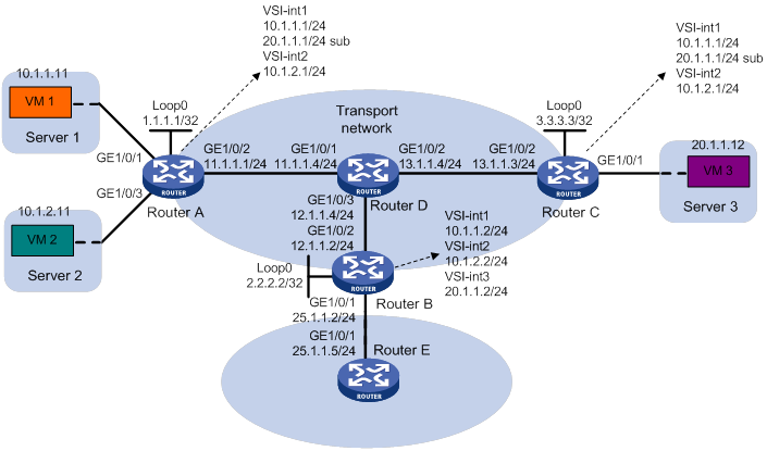
As shown in Figure 15:
· Configure VXLAN 10, VXLAN 20, and VXLAN 30 as unicast-mode VXLANs on Router A, Router B, and Router C to provide connectivity for the VMs across the network sites.
· Manually establish VXLAN tunnels and assign the tunnels to the VXLANs.
· Configure distributed VXLAN IP gateways on Router A and Router C to forward traffic between the VXLANs.
· Configure Router B as a border gateway to forward traffic between the VXLANs and the WAN connected to Router E.
Configuration procedure
1. On VM 1, VM 2, and VM 3, specify 10.1.1.1, 10.1.2.1, and 20.1.1.1 as the gateway address, respectively. (Details not shown.)
2. Configure IP addresses and unicast routing settings:
# Assign IP addresses to interfaces, as shown in Figure 15. (Details not shown.)
# Configure OSPF on all transport network routers (Routers A through D). (Details not shown.)
# Configure OSPF to advertise routes to networks 10.1.1.0/24, 10.1.2.0/24, 20.1.1.0/24, and 25.1.1.0/24 on Router B and Router E. (Details not shown.)
3. Configure Router A:
# Enable L2VPN.
<RouterA> system-view
[RouterA] l2vpn enable
# Create the VSI vpna and VXLAN 10.
[RouterA] vsi vpna
[RouterA-vsi-vpna] vxlan 10
[RouterA-vsi-vpna-vxlan-10] quit
[RouterA-vsi-vpna] quit
# Create the VSI vpnb and VXLAN 20.
[RouterA] vsi vpnb
[RouterA-vsi-vpnb] vxlan 20
[RouterA-vsi-vpnb-vxlan-20] quit
[RouterA-vsi-vpnb] quit
# Create the VSI vpnc and VXLAN 30.
[RouterA] vsi vpnc
[RouterA-vsi-vpnc] vxlan 30
[RouterA-vsi-vpnc-vxlan-30] quit
[RouterA-vsi-vpnc] quit
# Assign an IP address to Loopback 0. The IP address will be used as the source IP address of the VXLAN tunnels to Router B and Router C.
[RouterA] interface loopback 0
[RouterA-Loopback0] ip address 1.1.1.1 255.255.255.255
[RouterA-Loopback0] quit
# Create a VXLAN tunnel to Router B. The tunnel interface name is Tunnel 1.
[RouterA] interface tunnel 1 mode vxlan
[RouterA-Tunnel1] source 1.1.1.1
[RouterA-Tunnel1] destination 2.2.2.2
[RouterA-Tunnel1] quit
# Create a VXLAN tunnel to Router C. The tunnel interface name is Tunnel 2.
[RouterA] interface tunnel 2 mode vxlan
[RouterA-Tunnel2] source 1.1.1.1
[RouterA-Tunnel2] destination 3.3.3.3
[RouterA-Tunnel2] quit
# Assign Tunnel 1 and Tunnel 2 to VXLAN 10.
[RouterA] vsi vpna
[RouterA-vsi-vpna] vxlan 10
[RouterA-vsi-vpna-vxlan-10] tunnel 1
[RouterA-vsi-vpna-vxlan-10] tunnel 2
[RouterA-vsi-vpna-vxlan-10] quit
[RouterA-vsi-vpna] quit
# Assign Tunnel 1 and Tunnel 2 to VXLAN 20.
[RouterA] vsi vpnb
[RouterA-vsi-vpnb] vxlan 20
[RouterA-vsi-vpnb-vxlan-20] tunnel 1
[RouterA-vsi-vpnb-vxlan-20] tunnel 2
[RouterA-vsi-vpnb-vxlan-20] quit
[RouterA-vsi-vpnb] quit
# Assign Tunnel 2 to VXLAN 30.
[RouterA] vsi vpnc
[RouterA-vsi-vpnc] vxlan 30
[RouterA-vsi-vpnc-vxlan-30] tunnel 2
[RouterA-vsi-vpnc-vxlan-30] quit
[RouterA-vsi-vpnc] quit
# Map GigabitEthernet 1/0/1 to the VSI vpna.
[RouterA] interface gigabitethernet 1/0/1
[RouterA-GigabitEthernet1/0/1] xconnect vsi vpna
[RouterA-GigabitEthernet1/0/1] quit
# Map GigabitEthernet 1/0/3 to the VSI vpnb.
[RouterA] interface gigabitethernet 1/0/3
[RouterA-GigabitEthernet1/0/3] xconnect vsi vpnb
[RouterA-GigabitEthernet1/0/3] quit
# Create VSI-interface 1 and assign the interface an IP address and a MAC address. The IP address will be used as the gateway address for VXLAN 10.
[RouterA] interface vsi-interface 1
[RouterA-Vsi-interface1] ip address 10.1.1.1 255.255.255.0
[RouterA-Vsi-interface1] mac-address 1-1-1
# Specify VSI-interface 1 as a distributed gateway and enable local proxy ARP on the interface.
[RouterA-Vsi-interface1] distributed-gateway local
[RouterA-Vsi-interface1] local-proxy-arp enable
[RouterA-Vsi-interface1] quit
# Create VSI-interface 2 and assign the interface an IP address and a MAC address. The IP address will be used as the gateway address for VXLAN 20.
[RouterA] interface vsi-interface 2
[RouterA-Vsi-interface2] ip address 10.1.2.1 255.255.255.0
[RouterA-Vsi-interface1] mac-address 2-2-2
# Specify VSI-interface 2 as a distributed gateway and enable local proxy ARP on the interface.
[RouterA-Vsi-interface2] distributed-gateway local
[RouterA-Vsi-interface2] local-proxy-arp enable
[RouterA-Vsi-interface2] quit
# Specify VSI-interface 1 as the gateway interface for the VSI vpna. Assign subnet 10.1.1.0/24 to the VSI.
[RouterA] vsi vpna
[RouterA-vsi-vpna] gateway vsi-interface 1
[RouterA-vsi-vpna] gateway subnet 10.1.1.0 0.0.0.255
[RouterA-vsi-vpna] quit
# Specify VSI-interface 2 as the gateway interface for the VSI vpnb. Assign subnet 10.1.2.0/24 to the VSI.
[RouterA] vsi vpnb
[RouterA-vsi-vpnb] gateway vsi-interface 2
[RouterA-vsi-vpnb] gateway subnet 10.1.2.0 0.0.0.255
[RouterA-vsi-vpnb] quit
# Assign a secondary IP address to VSI-interface 1. The IP address will be used as the gateway address for VXLAN 30.
[RouterA] interface vsi-interface 1
[RouterA-Vsi-interface1] ip address 20.1.1.1 255.255.255.0 sub
[RouterA-Vsi-interface1] quit
# Specify VSI-interface 1 as the gateway interface for the VSI vpnc. Assign subnet 20.1.1.0/24 to the VSI.
[RouterA] vsi vpnc
[RouterA-vsi-vpnc] gateway vsi-interface 1
[RouterA-vsi-vpnc] gateway subnet 20.1.1.0 0.0.0.255
[RouterA-vsi-vpnc] quit
# Configure a routing policy for VXLAN 10. Set the policy name to vxlan10, and set the default next hop to 10.1.1.2 (VSI-interface 1 on Router B).
[RouterA] acl advanced 3000
[RouterA-acl-ipv4-adv-3000] rule 0 permit ip
[RouterA-acl-ipv4-adv-3000] quit
[RouterA] policy-based-route vxlan10 permit node 5
[RouterA-pbr-vxlan10-5] if-match acl 3000
[RouterA-pbr-vxlan10-5] apply default-next-hop 10.1.1.2
[RouterA-pbr-vxlan10-5] quit
# Configure a routing policy for VXLAN 20. Set the policy name to vxlan20, and set the default next hop to 10.1.2.2 (VSI-interface 2 on Router B).
[RouterA] policy-based-route vxlan20 permit node 5
[RouterA-pbr-vxlan20-5] if-match acl 3000
[RouterA-pbr-vxlan20-5] apply default-next-hop 10.1.2.2
[RouterA-pbr-vxlan20-5] quit
# Apply policies vxlan10 and vxlan20 to VSI-interface 1 and VSI-interface 2, respectively.
[RouterA] interface vsi-interface 1
[RouterA-Vsi-interface1] ip policy-based-route vxlan10
[RouterA-Vsi-interface1] quit
[RouterA] interface vsi-interface 2
[RouterA-Vsi-interface2] ip policy-based-route vxlan20
[RouterA-Vsi-interface2] quit
4. Configure Router B:
# Enable L2VPN.
<RouterB> system-view
[RouterB] l2vpn enable
# Create the VSI vpna and VXLAN 10.
[RouterB] vsi vpna
[RouterB-vsi-vpna] vxlan 10
[RouterB-vsi-vpna-vxlan-10] quit
[RouterB-vsi-vpna] quit
# Create the VSI vpnb and VXLAN 20.
[RouterB] vsi vpnb
[RouterB-vsi-vpnb] vxlan 20
[RouterB-vsi-vpnb-vxlan-20] quit
[RouterB-vsi-vpnb] quit
# Create the VSI vpnc and VXLAN 30.
[RouterB] vsi vpnc
[RouterB-vsi-vpnc] vxlan 30
[RouterB-vsi-vpnc-vxlan-30] quit
[RouterB-vsi-vpnc] quit
# Assign an IP address to Loopback 0. The IP address will be used as the source IP address of the VXLAN tunnels to Router A and Router C.
[RouterB] interface loopback 0
[RouterB-Loopback0] ip address 2.2.2.2 255.255.255.255
[RouterB-Loopback0] quit
# Create a VXLAN tunnel to Router A. The tunnel interface name is Tunnel 2.
[RouterB] interface tunnel 2 mode vxlan
[RouterB-Tunnel2] source 2.2.2.2
[RouterB-Tunnel2] destination 1.1.1.1
[RouterB-Tunnel2] quit
# Create a VXLAN tunnel to Router C. The tunnel interface name is Tunnel 3.
[RouterB] interface tunnel 3 mode vxlan
[RouterB-Tunnel3] source 2.2.2.2
[RouterB-Tunnel3] destination 3.3.3.3
[RouterB-Tunnel3] quit
# Assign Tunnel 2 to VXLAN 10.
[RouterB] vsi vpna
[RouterB-vsi-vpna] vxlan 10
[RouterB-vsi-vpna-vxlan-10] tunnel 2
[RouterB-vsi-vpna-vxlan-10] quit
[RouterB-vsi-vpna] quit
# Assign Tunnel 2 to VXLAN 20.
[RouterB] vsi vpnb
[RouterB-vsi-vpnb] vxlan 20
[RouterB-vsi-vpnb-vxlan-20] tunnel 2
[RouterB-vsi-vpnb-vxlan-20] quit
[RouterB-vsi-vpnb] quit
# Assign Tunnel 3 to VXLAN 30.
[RouterB] vsi vpnc
[RouterB-vsi-vpnc] vxlan 30
[RouterB-vsi-vpnc-vxlan-30] tunnel 3
[RouterB-vsi-vpnc-vxlan-30] quit
[RouterB-vsi-vpnc] quit
# Create VSI-interface 1 and assign the interface an IP address.
[RouterB] interface vsi-interface 1
[RouterB-Vsi-interface1] ip address 10.1.1.2 255.255.255.0
[RouterB-Vsi-interface1] quit
# Create VSI-interface 2 and assign the interface an IP address.
[RouterB] interface vsi-interface 2
[RouterB-Vsi-interface2] ip address 10.1.2.2 255.255.255.0
[RouterB-Vsi-interface2] quit
# Create VSI-interface 3 and assign the interface an IP address.
[RouterB] interface vsi-interface 3
[RouterB-Vsi-interface3] ip address 20.1.1.2 255.255.255.0
[RouterB-Vsi-interface3] quit
# Specify VSI-interface 1 as the gateway interface for the VSI vpna.
[RouterB] vsi vpna
[RouterB-vsi-vpna] gateway vsi-interface 1
[RouterB-vsi-vpna] quit
# Specify VSI-interface 2 as the gateway interface for the VSI vpnb.
[RouterB] vsi vpnb
[RouterB-vsi-vpnb] gateway vsi-interface 2
[RouterB-vsi-vpnb] quit
# Specify VSI-interface 3 as the gateway interface for the VSI vpnc.
[RouterB] vsi vpnc
[RouterB-vsi-vpnc] gateway vsi-interface 3
[RouterB-vsi-vpnc] quit
5. Configure Router C:
# Enable L2VPN.
<RouterC> system-view
[RouterC] l2vpn enable
# Create the VSI vpna and VXLAN 10.
[RouterC] vsi vpna
[RouterC-vsi-vpna] vxlan 10
[RouterC-vsi-vpna-vxlan-10] quit
[RouterC-vsi-vpna] quit
# Create the VSI vpnb and VXLAN 20.
[RouterC] vsi vpnb
[RouterC-vsi-vpnb] vxlan 20
[RouterC-vsi-vpnb-vxlan-20] quit
[RouterC-vsi-vpnb] quit
# Create the VSI vpnc and VXLAN 30.
[RouterC] vsi vpnc
[RouterC-vsi-vpnc] vxlan 30
[RouterC-vsi-vpnc-vxlan-30] quit
[RouterC-vsi-vpnc] quit
# Assign an IP address to Loopback 0. The IP address will be used as the source IP address of the VXLAN tunnels to Router A and Router B.
[RouterC] interface loopback 0
[RouterC-Loopback0] ip address 3.3.3.3 255.255.255.255
[RouterC-Loopback0] quit
# Create a VXLAN tunnel to Router A. The tunnel interface name is Tunnel 1.
[RouterC] interface tunnel 1 mode vxlan
[RouterC-Tunnel1] source 3.3.3.3
[RouterC-Tunnel1] destination 1.1.1.1
[RouterC-Tunnel1] quit
# Create a VXLAN tunnel to Router B. The tunnel interface name is Tunnel 3.
[RouterC] interface tunnel 3 mode vxlan
[RouterC-Tunnel3] source 3.3.3.3
[RouterC-Tunnel3] destination 2.2.2.2
[RouterC-Tunnel3] quit
# Assign Tunnel 1 to VXLAN 10.
[RouterC] vsi vpna
[RouterC-vsi-vpna] vxlan 10
[RouterC-vsi-vpna-vxlan-10] tunnel 1
[RouterC-vsi-vpna-vxlan-10] quit
[RouterC-vsi-vpna] quit
# Assign Tunnel 1 to VXLAN 20.
[RouterC] vsi vpnb
[RouterC-vsi-vpnb] vxlan 20
[RouterC-vsi-vpnb-vxlan-20] tunnel 1
[RouterC-vsi-vpnb-vxlan-20] quit
[RouterC-vsi-vpnb] quit
# Assign Tunnel 1 and Tunnel 3 to VXLAN 30.
[RouterC] vsi vpnc
[RouterC-vsi-vpnc] vxlan 30
[RouterC-vsi-vpnc-vxlan-30] tunnel 1
[RouterC-vsi-vpnc-vxlan-30] tunnel 3
[RouterC-vsi-vpnc-vxlan-30] quit
[RouterC-vsi-vpnc] quit
# Map GigabitEthernet 1/0/1 to the VSI vpnc.
[RouterC] interface gigabitethernet 1/0/1
[RouterC-GigabitEthernet1/0/1] xconnect vsi vpnc
[RouterC-GigabitEthernet1/0/1] quit
# Create VSI-interface 1 and assign the interface an IP address and a MAC address. The IP address will be used as the gateway address for VXLAN 10.
[RouterC] interface vsi-interface 1
[RouterC-Vsi-interface1] ip address 10.1.1.1 255.255.255.0
[RouterC-Vsi-interface1] mac-address 1-1-1
# Specify VSI-interface 1 as a distributed gateway and enable local proxy ARP on the interface.
[RouterC-Vsi-interface1] distributed-gateway local
[RouterC-Vsi-interface1] local-proxy-arp enable
[RouterC-Vsi-interface1] quit
# Create VSI-interface 2 and assign the interface an IP address and a MAC address. The IP address will be used as the gateway address for VXLAN 20.
[RouterC] interface vsi-interface 2
[RouterC-Vsi-interface2] ip address 10.1.2.1 255.255.255.0
[RouterC-Vsi-interface2] mac-address 2-2-2
# Specify VSI-interface 2 as a distributed gateway and enable local proxy ARP on the interface.
[RouterC-Vsi-interface2] distributed-gateway local
[RouterC-Vsi-interface2] local-proxy-arp enable
[RouterC-Vsi-interface2] quit
# Specify VSI-interface 1 as the gateway interface for the VSI vpna. Assign subnet 10.1.1.0/24 to the VSI.
[RouterC] vsi vpna
[RouterC-vsi-vpna] gateway vsi-interface 1
[RouterC-vsi-vpna] gateway subnet 10.1.1.0 0.0.0.255
[RouterC-vsi-vpna] quit
# Specify VSI-interface 2 as the gateway interface for the VSI vpnb.
[RouterC] vsi vpnb
[RouterC-vsi-vpnb] gateway vsi-interface 2
[RouterC-vsi-vpnb] quit
# Assign a secondary IP address to VSI-interface 1. The IP address will be used as the gateway address for VXLAN 30.
[RouterC] interface vsi-interface 1
[RouterC-Vsi-interface1] ip address 20.1.1.1 255.255.255.0 sub
[RouterC-Vsi-interface1] quit
# Specify VSI-interface 1 as the gateway interface for the VSI vpnc. Assign subnet 20.1.1.0/24 to the VSI.
[RouterC] vsi vpnc
[RouterC-vsi-vpnc] gateway vsi-interface 1
[RouterC-vsi-vpnc] gateway subnet 20.1.1.0 0.0.0.255
[RouterC-vsi-vpnc] quit
# Configure a routing policy for the VXLANs. Set the policy name to vxlan, and set the default next hop to 20.1.1.2 (VSI-interface 1 on Router B).
[RouterC] acl advanced 3000
[RouterC-acl-ipv4-adv-3000] rule 0 permit ip
[RouterC-acl-ipv4-adv-3000] quit
[RouterC] policy-based-route vxlan permit node 5
[RouterC-pbr-vxlan-5] if-match acl 3000
[RouterC-pbr-vxlan-5] apply default-next-hop 20.1.1.2
[RouterC-pbr-vxlan-5] quit
# Apply the policy vxlan to VSI-interface 1.
[RouterC] interface Vsi-interface1
[RouterC-Vsi-interface1] ip policy-based-route vxlan
[RouterC-Vsi-interface1] quit
Verifying the configuration
1. Verify the distributed VXLAN IP gateway settings on Router A:
# Verify that the VXLAN tunnel interfaces are up on Router A.
[RouterA] display interface tunnel 2
Tunnel2
Current state: UP
Line protocol state: UP
Description: Tunnel2 Interface
Bandwidth: 64 kbps
Maximum transmission unit: 1464
Internet protocol processing: Disabled
Output queue - Urgent queuing: Size/Length/Discards 0/1024/0
Output queue - Protocol queuing: Size/Length/Discards 0/500/0
Output queue - FIFO queuing: Size/Length/Discards 0/75/0
Last clearing of counters: Never
Tunnel source 1.1.1.1, destination 3.3.3.3
Tunnel protocol/transport UDP_VXLAN/IP
Last 300 seconds input rate: 0 bytes/sec, 0 bits/sec, 0 packets/sec
Last 300 seconds output rate: 0 bytes/sec, 0 bits/sec, 0 packets/sec
Input: 0 packets, 0 bytes, 0 drops
Output: 0 packets, 0 bytes, 0 drops
# Verify that VSI-interface 1 is up.
[RouterA] display interface vsi-interface 1
Vsi-interface1
Current state: UP
Line protocol state: UP
Description: Vsi-interface1 Interface
Bandwidth: 1000000 kbps
Maximum transmission unit: 1500
Internet address: 10.1.1.1/24 (primary)
IP packet frame type: Ethernet II, hardware address: 0011-2200-0102
IPv6 packet frame type: Ethernet II, hardware address: 0011-2200-0102
Physical: Unknown, baudrate: 1000000 kbps
Last clearing of counters: Never
Last 300 seconds input rate: 0 bytes/sec, 0 bits/sec, 0 packets/sec
Last 300 seconds output rate: 0 bytes/sec, 0 bits/sec, 0 packets/sec
Input: 0 packets, 0 bytes, 0 drops
Output: 0 packets, 0 bytes, 0 drops
# Verify that the VXLAN tunnels have been assigned to VXLAN 10, and VSI-interface 1 is the gateway interface for the VSI vpna.
[RouterA] display l2vpn vsi name vpna verbose
VSI Name: vpna
VSI Index : 0
VSI State : Up
MTU : 1500
Bandwidth : -
Broadcast Restrain : -
Multicast Restrain : -
Unknown Unicast Restrain: -
MAC Learning : Enabled
MAC Table Limit : -
Mac Learning rate : -
Drop Unknown : -
Flooding : Enabled
Gateway interface : VSI-interface 1
VXLAN ID : 10
Tunnels:
Tunnel Name Link ID State Type Flood proxy
Tunnel1 0x5000001 Up Manual Disabled
Tunnel2 0x5000002 Up Manual Disabled
ACs:
AC Link ID State
GE1/0/1 0 Up
# Verify that Router A has created ARP entries for the VMs.
[RouterA] display arp
Type: S-Static D-Dynamic O-Openflow M-Multiport I-Invalid
IP address MAC address SVLAN/VSI Interface/Link ID Aging Type
11.1.1.4 000c-29c1-5e46 -- GE1/0/2 19 D
10.1.1.2 0003-0000-0000 -- Tunnel1 20 D
10.1.1.11 0cda-41b5-cf09 -- 0 20 D
10.1.2.2 0004-0000-0000 -- Tunnel1 20 D
10.1.2.11 0cda-41b5-cf89 -- 0 20 D
20.1.1.12 0001-0001-0001 -- Tunnel2 19 D
2. Verify the configuration on the border gateway Router B:
# Verify that the VXLAN tunnel interfaces are up on Router B.
[RouterB] display interface tunnel 2
Tunnel2
Current state: UP
Line protocol state: UP
Description: Tunnel2 Interface
Bandwidth: 64 kbps
Maximum transmission unit: 1464
Internet protocol processing: Disabled
Output queue - Urgent queuing: Size/Length/Discards 0/1024/0
Output queue - Protocol queuing: Size/Length/Discards 0/500/0
Output queue - FIFO queuing: Size/Length/Discards 0/75/0
Last clearing of counters: Never
Tunnel source 2.2.2.2, destination 1.1.1.1
Tunnel protocol/transport UDP_VXLAN/IP
Last 300 seconds input rate: 0 bytes/sec, 0 bits/sec, 0 packets/sec
Last 300 seconds output rate: 0 bytes/sec, 0 bits/sec, 0 packets/sec
Input: 0 packets, 0 bytes, 0 drops
Output: 0 packets, 0 bytes, 0 drops
# Verify that VSI-interface 1 is up.
[RouterB] display interface vsi-interface 1
Vsi-interface1
Current state: UP
Line protocol state: UP
Description: Vsi-interface1 Interface
Bandwidth: 1000000 kbps
Maximum transmission unit: 1500
Internet address: 10.1.1.2/24 (primary)
IP packet frame type: Ethernet II, hardware address: 0011-2200-0102
IPv6 packet frame type: Ethernet II, hardware address: 0011-2200-0102
Physical: Unknown, baudrate: 1000000 kbps
Last clearing of counters: Never
Last 300 seconds input rate: 0 bytes/sec, 0 bits/sec, 0 packets/sec
Last 300 seconds output rate: 0 bytes/sec, 0 bits/sec, 0 packets/sec
Input: 0 packets, 0 bytes, 0 drops
Output: 0 packets, 0 bytes, 0 drops
# Verify that the VXLAN tunnels have been assigned to VXLAN 10, and VSI-interface 1 is the gateway interface for the VSI vpna.
[RouterB] display l2vpn vsi name vpna verbose
VSI Name: vpna
VSI Index : 0
VSI State : Up
MTU : 1500
Bandwidth : -
Broadcast Restrain : -
Multicast Restrain : -
Unknown Unicast Restrain: -
MAC Learning : Enabled
MAC Table Limit : -
Mac Learning rate : -
Drop Unknown : -
Flooding : Enabled
Gateway interface : VSI-interface 1
VXLAN ID : 10
Tunnels:
Tunnel Name Link ID State Type Flood proxy
Tunnel2 0x5000002 Up Manual Disabled
# Verify that Router B has created ARP entries for the VMs.
[RouterB] display arp
Type: S-Static D-Dynamic O-Openflow M-Multiport I-Invalid
IP address MAC address SVLAN/VSI Interface/Link ID Aging Type
12.1.1.4 0000-fc00-00ab -- GE1/0/2 14 D
25.1.1.5 4431-9234-24bb -- GE1/0/1 17 D
10.1.1.1 0001-0001-0001 0 Tunnel2 17 D
10.1.1.11 0001-0001-0001 0 Tunnel2 20 D
10.1.2.1 0002-0002-0002 1 Tunnel2 17 D
10.1.1.11 0002-0002-0002 1 Tunnel2 20 D
20.1.1.1 0001-0001-0001 2 Tunnel3 17 D
20.1.1.12 0001-0001-0001 2 Tunnel3 20 D
# Verify that Router B has created FIB entries for the VMs.
[RouterB] display fib 10.1.1.11
Destination count: 1 FIB entry count: 1
Flag:
U:Usable G:Gateway H:Host B:Blackhole D:Dynamic S:Static
R:Relay F:FRR
Destination/Mask Nexthop Flag OutInterface/Token Label
10.1.1.11/32 10.1.1.11 UH Vsi1 Null
[RouterB] display fib 20.1.1.12
Destination count: 1 FIB entry count: 1
Flag:
U:Usable G:Gateway H:Host B:Blackhole D:Dynamic S:Static
R:Relay F:FRR
Destination/Mask Nexthop Flag OutInterface/Token Label
20.1.1.12/32 20.1.1.12 UH Vsi3 Null
3. Verify the network connectivity for VMs:
# Verify that VM 1, VM 2, and VM 3 can ping one another. (Details not shown.)
# Verify that VM 1, VM 2, and VM 3 can ping GigabitEthernet 1/0/1 (25.1.1.5) on Router E for WAN access. (Details not shown.)
Distributed VXLAN IPv6 gateway configuration example
Network requirements
As shown in Figure 16:
· Configure VXLAN 10 and VXLAN 20 as unicast-mode VXLANs on Router A, Router B, and Router C to provide connectivity for the VMs across the network sites.
· Manually establish VXLAN tunnels and assign the tunnels to the VXLANs.
· Configure distributed VXLAN IP gateways on Router A and Router C to forward traffic between VXLANs.
· Configure Router B as a border gateway to forward traffic between the VXLANs and the WAN connected to Router E.
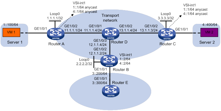
Configuration procedure
1. On VM 1 and VM 2, specify 1::1 and 4::1 as the gateway address, respectively. (Details not shown.)
2. Configure IP addresses and unicast routing settings:
# Assign IP addresses to interfaces, as shown in Figure 16. (Details not shown.)
# Configure OSPF on all transport network routers (Routers A through D). (Details not shown.)
# Configure OSPFv3 to advertise routes to networks 1::/64, 4::/64, and 3::/64 on Router B and Router E. (Details not shown.)
3. Configure Router A:
# Enable L2VPN.
<RouterA> system-view
[RouterA] l2vpn enable
# Create the VSI vpna and VXLAN 10.
[RouterA] vsi vpna
[RouterA-vsi-vpna] vxlan 10
[RouterA-vsi-vpna-vxlan-10] quit
[RouterA-vsi-vpna] quit
# Create the VSI vpnb and VXLAN 20.
[RouterA] vsi vpnb
[RouterA-vsi-vpnb] vxlan 20
[RouterA-vsi-vpnb-vxlan-20] quit
[RouterA-vsi-vpnb] quit
# Assign an IP address to Loopback 0. The IP address will be used as the source IP address of the VXLAN tunnels to Router B and Router C.
[RouterA] interface loopback 0
[RouterA-Loopback0] ip address 1.1.1.1 255.255.255.255
[RouterA-Loopback0] quit
# Create a VXLAN tunnel to Router B. The tunnel interface name is Tunnel 1.
[RouterA] interface tunnel 1 mode vxlan
[RouterA-Tunnel1] source 1.1.1.1
[RouterA-Tunnel1] destination 2.2.2.2
[RouterA-Tunnel1] quit
# Create a VXLAN tunnel to Router C. The tunnel interface name is Tunnel 2.
[RouterA] interface tunnel 2 mode vxlan
[RouterA-Tunnel2] source 1.1.1.1
[RouterA-Tunnel2] destination 3.3.3.3
[RouterA-Tunnel2] quit
# Assign Tunnel 1 and Tunnel 2 to VXLAN 10.
[RouterA] vsi vpna
[RouterA-vsi-vpna] vxlan 10
[RouterA-vsi-vpna-vxlan-10] tunnel 1
[RouterA-vsi-vpna-vxlan-10] tunnel 2
[RouterA-vsi-vpna-vxlan-10] quit
[RouterA-vsi-vpna] quit
# Assign Tunnel 1 and Tunnel 2 to VXLAN 20.
[RouterA] vsi vpnb
[RouterA-vsi-vpnb] vxlan 20
[RouterA-vsi-vpnb-vxlan-20] tunnel 1
[RouterA-vsi-vpnb-vxlan-20] tunnel 2
[RouterA-vsi-vpnb-vxlan-20] quit
[RouterA-vsi-vpnb] quit
# Map GigabitEthernet 1/0/1 to the VSI vpna.
[RouterA] interface gigabitethernet 1/0/1
[RouterA-GigabitEthernet1/0/1] xconnect vsi vpna
[RouterA-GigabitEthernet1/0/1] quit
# Create VSI-interface 1 and assign the interface two IPv6 anycast addresses. The IP addresses will be used as gateway addresses for VXLAN 10 and VXLAN 20.
[RouterA] interface vsi-interface 1
[RouterA-Vsi-interface1] ipv6 address 1::1/64 anycast
[RouterA-Vsi-interface1] ipv6 address 4::1/64 anycast
# Specify VSI-interface 1 as a distributed gateway and enable local ND proxy on the interface.
[RouterA-Vsi-interface1] distributed-gateway local
[RouterA-Vsi-interface1] local-proxy-nd enable
[RouterA-Vsi-interface1] quit
# Specify VSI-interface 1 as the gateway interface for the VSI vpna. Assign subnet 1::1/64 to the VSI.
[RouterA] vsi vpna
[RouterA-vsi-vpna] gateway vsi-interface 1
[RouterA-vsi-vpna] gateway subnet 1::1 64
[RouterA-vsi-vpna] quit
# Specify VSI-interface 1 as the gateway interface for the VSI vpnb. Assign subnet 4::1/64 to the VSI.
[RouterA] vsi vpnb
[RouterA-vsi-vpnb] gateway vsi-interface 1
[RouterA-vsi-vpnb] gateway subnet 4::1 64
[RouterA-vsi-vpnb] quit
# Configure an IPv6 static route. Set the destination address to 3::/64 and the next hop to 1::2.
[RouterA] ipv6 route-static 3:: 64 1::2
4. Configure Router B:
# Enable L2VPN.
<RouterB> system-view
[RouterB] l2vpn enable
# Create the VSI vpna and VXLAN 10.
[RouterB] vsi vpna
[RouterB-vsi-vpna] vxlan 10
[RouterB-vsi-vpna-vxlan-10] quit
[RouterB-vsi-vpna] quit
# Create the VSI vpnb and VXLAN 20.
[RouterB] vsi vpnb
[RouterB-vsi-vpnb] vxlan 20
[RouterB-vsi-vpnb-vxlan-20] quit
[RouterB-vsi-vpnb] quit
# Assign an IP address to Loopback 0. The IP address will be used as the source IP address of the VXLAN tunnels to Router A and Router C.
[RouterB] interface loopback 0
[RouterB-Loopback0] ip address 2.2.2.2 255.255.255.255
[RouterB-Loopback0] quit
# Create a VXLAN tunnel to Router A. The tunnel interface name is Tunnel 2.
[RouterB] interface tunnel 2 mode vxlan
[RouterB-Tunnel2] source 2.2.2.2
[RouterB-Tunnel2] destination 1.1.1.1
[RouterB-Tunnel2] quit
# Create a VXLAN tunnel to Router C. The tunnel interface name is Tunnel 3.
[RouterB] interface tunnel 3 mode vxlan
[RouterB-Tunnel3] source 2.2.2.2
[RouterB-Tunnel3] destination 3.3.3.3
[RouterB-Tunnel3] quit
# Assign Tunnel 2 and Tunnel 3 to VXLAN 10.
[RouterB] vsi vpna
[RouterB-vsi-vpna] vxlan 10
[RouterB-vsi-vpna-vxlan-10] tunnel 2
[RouterB-vsi-vpna-vxlan-10] tunnel 3
[RouterB-vsi-vpna-vxlan-10] quit
[RouterB-vsi-vpna] quit
# Assign Tunnel 2 and Tunnel 3 to VXLAN 20.
[RouterB] vsi vpnb
[RouterB-vsi-vpnb] vxlan 20
[RouterB-vsi-vpnb-vxlan-20] tunnel 2
[RouterB-vsi-vpnb-vxlan-20] tunnel 3
[RouterB-vsi-vpnb-vxlan-20] quit
[RouterB-vsi-vpnb] quit
# Create VSI-interface 1 and assign the interface IPv6 addresses.
[RouterB] interface vsi-interface 1
[RouterB-Vsi-interface1] ipv6 address 1::2/64
[RouterB-Vsi-interface1] ipv6 address 4::2/64
[RouterB-Vsi-interface1] quit
# Specify VSI-interface 1 as the gateway interface for the VSI vpna.
[RouterB] vsi vpna
[RouterB-vsi-vpna] gateway vsi-interface 1
[RouterB-vsi-vpna] quit
# Specify VSI-interface 2 as the gateway interface for the VSI vpnb.
[RouterB] vsi vpnb
[RouterB-vsi-vpnb] gateway vsi-interface 1
[RouterB-vsi-vpnb] quit
5. Configure Router C:
# Enable L2VPN.
<RouterC> system-view
[RouterC] l2vpn enable
# Create the VSI vpna and VXLAN 10.
[RouterC] vsi vpna
[RouterC-vsi-vpna] vxlan 10
[RouterC-vsi-vpna-vxlan-10] quit
[RouterC-vsi-vpna] quit
# Create the VSI vpnb and VXLAN 20.
[RouterC] vsi vpnb
[RouterC-vsi-vpnb] vxlan 20
[RouterC-vsi-vpnb-vxlan-20] quit
[RouterC-vsi-vpnb] quit
# Assign an IP address to Loopback 0. The IP address will be used as the source IP address of the VXLAN tunnels to Router A and Router B.
[RouterC] interface loopback 0
[RouterC-Loopback0] ip address 3.3.3.3 255.255.255.255
[RouterC-Loopback0] quit
# Create a VXLAN tunnel to Router A. The tunnel interface name is Tunnel 1.
[RouterC] interface tunnel 1 mode vxlan
[RouterC-Tunnel1] source 3.3.3.3
[RouterC-Tunnel1] destination 1.1.1.1
[RouterC-Tunnel1] quit
# Create a VXLAN tunnel to Router B. The tunnel interface name is Tunnel 3.
[RouterC] interface tunnel 3 mode vxlan
[RouterC-Tunnel3] source 3.3.3.3
[RouterC-Tunnel3] destination 2.2.2.2
[RouterC-Tunnel3] quit
# Assign Tunnel 1 and Tunnel 3 to VXLAN 10.
[RouterC] vsi vpna
[RouterC-vsi-vpna] vxlan 10
[RouterC-vsi-vpna-vxlan-10] tunnel 1
[RouterC-vsi-vpna-vxlan-10] tunnel 3
[RouterC-vsi-vpna-vxlan-10] quit
[RouterC-vsi-vpna] quit
#Assign Tunnel 1 and Tunnel 3 to VXLAN 20.
[RouterC] vsi vpnb
[RouterC-vsi-vpnb] vxlan 20
[RouterC-vsi-vpnb-vxlan-20] tunnel 1
[RouterC-vsi-vpnb-vxlan-20] tunnel 3
[RouterC-vsi-vpnb-vxlan-20] quit
[RouterC-vsi-vpnb] quit
# Map GigabitEthernet 1/0/1 to the VSI vpnb.
[RouterC] interface gigabitethernet 1/0/1
[RouterC-GigabitEthernet1/0/1] xconnect vsi vpnb
[RouterC-GigabitEthernet1/0/1] quit
# Create VSI-interface 1 and assign the interface two IPv6 anycast addresses. The IP addresses will be used as gateway addresses for VXLAN 10 and VXLAN 20.
[RouterC] interface vsi-interface 1
[RouterC-Vsi-interface1] ipv6 address 1::1/64 anycast
[RouterC-Vsi-interface1] ipv6 address 4::1/64 anycast
# Specify VSI-interface 1 as a distributed gateway and enable local ND proxy on the interface.
[RouterC-Vsi-interface1] distributed-gateway local
[RouterC-Vsi-interface1] local-proxy-nd enable
[RouterC-Vsi-interface1] quit
# Specify VSI-interface 1 as the gateway interface for the VSI vpna. Assign subnet 1::1/64 to the VSI.
[RouterC] vsi vpna
[RouterC-vsi-vpna] gateway vsi-interface 1
[RouterC-vsi-vpna] gateway subnet 1::1 64
[RouterC-vsi-vpna] quit
# Specify VSI-interface 1 as the gateway interface for the VSI vpnb. Assign subnet 4::1/64 to the VSI.
[RouterC] vsi vpnb
[RouterC-vsi-vpnb] gateway vsi-interface 1
[RouterC-vsi-vpnb] gateway subnet 4::1 64
[RouterC-vsi-vpnb] quit
# Configure an IPv6 static route. Set the destination address to 3::/64 and the next hop to 4::2.
[RouterC] ipv6 route-static 3:: 64 4::2
Verifying the configuration
1. Verify the distributed VXLAN IP gateway settings on Router A:
# Verify that the VXLAN tunnel interfaces are up on Router A.
[RouterA] display interface tunnel 2
Tunnel2
Current state: UP
Line protocol state: UP
Description: Tunnel2 Interface
Bandwidth: 64 kbps
Maximum transmission unit: 1464
Internet protocol processing: Disabled
Output queue - Urgent queuing: Size/Length/Discards 0/1024/0
Output queue - Protocol queuing: Size/Length/Discards 0/500/0
Output queue - FIFO queuing: Size/Length/Discards 0/75/0
Last clearing of counters: Never
Tunnel source 1.1.1.1, destination 3.3.3.3
Tunnel protocol/transport UDP_VXLAN/IP
Last 300 seconds input rate: 0 bytes/sec, 0 bits/sec, 0 packets/sec
Last 300 seconds output rate: 0 bytes/sec, 0 bits/sec, 0 packets/sec
Input: 0 packets, 0 bytes, 0 drops
Output: 0 packets, 0 bytes, 0 drops
# Verify that VSI-interface 1 is up.
[RouterA] display interface vsi-interface 1
Vsi-interface1
Current state: UP
Line protocol state: UP
Description: Vsi-interface1 Interface
Bandwidth: 1000000 kbps
Maximum transmission unit: 1500
Internet protocol processing: Disabled
IP packet frame type: Ethernet II, hardware address: 0011-2200-0102
IPv6 packet frame type: Ethernet II, hardware address: 0011-2200-0102
Physical: Unknown, baudrate: 1000000 kbps
Last clearing of counters: Never
Last 300 seconds input rate: 0 bytes/sec, 0 bits/sec, 0 packets/sec
Last 300 seconds output rate: 0 bytes/sec, 0 bits/sec, 0 packets/sec
Input: 0 packets, 0 bytes, 0 drops
Output: 0 packets, 0 bytes, 0 drops
# Verify that the VXLAN tunnels have been assigned to VXLAN 10 and VXLAN 20, and VSI-interface 1 is the gateway interface for the VSIs vpna and vpnb.
[RouterA] display l2vpn vsi verbose
VSI Name: vpna
VSI Index : 0
VSI State : Up
MTU : 1500
Bandwidth : -
Broadcast Restrain : -
Multicast Restrain : -
Unknown Unicast Restrain: -
MAC Learning : Enabled
MAC Table Limit : -
Mac Learning rate : -
Drop Unknown : -
Flooding : Enabled
Gateway Interface : VSI-interface 1
VXLAN ID : 10
Tunnels:
Tunnel Name Link ID State Type Flood proxy
Tunnel1 0x5000001 Up Manual Disabled
Tunnel2 0x5000002 Up Manual Disabled
ACs:
AC Link ID State
GE1/0/1 0 Up
VSI Name: vpnb
VSI Index : 1
VSI State : Up
MTU : 1500
Bandwidth : -
Broadcast Restrain : -
Multicast Restrain : -
Unknown Unicast Restrain: -
MAC Learning : Enabled
MAC Table Limit : -
Mac Learning rate : -
Drop Unknown : -
Flooding : Enabled
Gateway Interface : VSI-interface 1
VXLAN ID : 20
Flood proxy : Disable
Tunnels:
Tunnel Name Link ID State Type Flood proxy
Tunnel1 0x5000001 Up Manual Disabled
Tunnel2 0x5000002 Up Manual Disabled
# Verify that Router A has created neighbor entries for the VMs.
[RouterA] display ipv6 neighbors all
Type: S-Static D-Dynamic O-Openflow R-Rule I-Invalid
IPv6 address Link layer VID Interface State T Age
1::2 3c8c-400d-867a N/A Vsi1 STALE D 7
1::100 0001-0000-0047 N/A 0 STALE D 22
4::400 0002-0000-0047 N/A Vsi2 REACH D 5
FE80::201:FF:FE00:47 0001-0000-0047 N/A Vsi1 REACH D 30
FE80::202:FF:FE00:0 0002-0000-0000 N/A Vsi2 REACH D 27
FE80::202:FF:FE00:47 0002-0000-0047 N/A 0 DELAY D 5
# Verify that Router A has created FIB entries for the VMs.
[RouterA] display ipv6 fib 4::400
Destination count: 1 FIB entry count: 1
Flag:
U:Usable G:Gateway H:Host B:Blackhole D:Dynamic S:Static
R:Relay F:FRR
Destination: 4::400 Prefix length: 128
Nexthop : 4::400 Flags: UH
Time stamp : 0x2c Label: Null
Interface : Vsi2 Token: Invalid
[RouterA] display ipv6 fib 3::300
Destination count: 1 FIB entry count: 1
Flag:
U:Usable G:Gateway H:Host B:Blackhole D:Dynamic S:Static
R:Relay F:FRR
Destination: 3:: Prefix length: 64
Nexthop : 1::2 Flags: USGR
Time stamp : 0x23 Label: Null
Interface : Vsi1 Token: Invalid
2. Verify the configuration on the border gateway Router B:
# Verify that the VXLAN tunnel interfaces are up on Router B.
[RouterB] display interface tunnel 2
Tunnel2
Current state: UP
Line protocol state: UP
Description: Tunnel2 Interface
Bandwidth: 64 kbps
Maximum transmission unit: 1464
Internet protocol processing: Disabled
Output queue - Urgent queuing: Size/Length/Discards 0/1024/0
Output queue - Protocol queuing: Size/Length/Discards 0/500/0
Output queue - FIFO queuing: Size/Length/Discards 0/75/0
Last clearing of counters: Never
Tunnel source 2.2.2.2, destination 1.1.1.1
Tunnel protocol/transport UDP_VXLAN/IP
Last 300 seconds input rate: 0 bytes/sec, 0 bits/sec, 0 packets/sec
Last 300 seconds output rate: 0 bytes/sec, 0 bits/sec, 0 packets/sec
Input: 0 packets, 0 bytes, 0 drops
Output: 0 packets, 0 bytes, 0 drops
# Verify that VSI-interface 1 is up.
[RouterB] display interface vsi-interface 1
Vsi-interface1
Current state: UP
Line protocol state: UP
Description: Vsi-interface1 Interface
Bandwidth: 1000000 kbps
Maximum transmission unit: 1500
Internet protocol processing: Disabled
IP packet frame type: Ethernet II, hardware address: 0011-0022-0102
IPv6 packet frame type: Ethernet II, hardware address: 0011-0022-0102
Physical: Unknown, baudrate: 1000000 kbps
Last clearing of counters: Never
Last 300 seconds input rate: 0 bytes/sec, 0 bits/sec, 0 packets/sec
Last 300 seconds output rate: 0 bytes/sec, 0 bits/sec, 0 packets/sec
Input: 0 packets, 0 bytes, 0 drops
Output: 0 packets, 0 bytes, 0 drops
# Verify that the VXLAN tunnels have been assigned to VXLAN 10, and VSI-interface 1 is the gateway interface of the VSI vpna.
[RouterB] display l2vpn vsi name vpna verbose
VSI Name: vpna
VSI Index : 0
VSI State : Up
MTU : 1500
Bandwidth : -
Broadcast Restrain : -
Multicast Restrain : -
Unknown Unicast Restrain: -
MAC Learning : Enabled
MAC Table Limit : -
MAC Learning rate : -
Drop Unknown : -
Flooding : Enabled
Gateway interface : VSI-interface 1
VXLAN ID : 10
Tunnels:
Tunnel Name Link ID State Type Flood proxy
Tunnel2 0x5000001 Up Manual Disabled
Tunnel3 0x5000002 Up Manual Disabled
# Verify that Router B has created neighbor entries for the VMs.
[RouterB] display ipv6 neighbors all
Type: S-Static D-Dynamic O-Openflow R-Rule I-Invalid
IPv6 address Link layer VID Interface State T Age
3::300 0003-0000-0047 N/A GE1/0/1 DELAY D 3
FE80::203:FF:FE00:47 0003-0000-0047 N/A GE1/0/1 STALE D 222
1::100 0001-0000-0047 N/A Vsi1 STALE D 232
4::400 0002-0000-0047 N/A Vsi1 REACH D 3
FE80::201:FF:FE00:0 0001-0000-0000 N/A Vsi1 STALE D 237
FE80::201:FF:FE00:47 0001-0000-0047 N/A GE1/0/1 STALE D 222
FE80::202:FF:FE00:0 0002-0000-0000 N/A Vsi1 STALE D 345
# Verify that Router B has created FIB entries for the VMs.
[RouterB] display ipv6 fib 1::100
Destination count: 1 FIB entry count: 1
Flag:
U:Usable G:Gateway H:Host B:Blackhole D:Dynamic S:Static
R:Relay F:FRR
Destination: 1::100 Prefix length: 128
Nexthop : 1::100 Flags: UH
Time stamp : 0x21 Label: Null
Interface : Vsi1 Token: Invalid
[RouterB] display ipv6 fib 4::400
Destination count: 1 FIB entry count: 1
Flag:
U:Usable G:Gateway H:Host B:Blackhole D:Dynamic S:Static
R:Relay F:FRR
Destination: 4:: Prefix length: 64
Nexthop : :: Flags: U
Time stamp : 0x19 Label: Null
Interface : Vsi1 Token: Invalid
3. Verify that the network connectivity for the VMs meet the network requirements:
# Verify that VM 1 and VM 2 can ping each other. (Details not shown.)
# Verify that VM 1, VM 2, and GigabitEthernet 1/0/1 (3::300) on Router E can ping each other. (Details not shown.)
Configuring ENDP
Overview
Enhanced Neighbor Discovery Protocol (ENDP) dynamically discovers VTEPs and establishes VXLAN tunnels.
Working mechanism
ENDP supports multiple VXLAN networks. ENDP uses network IDs to uniquely identify VXLANs. VTEPs can discover each other if they have the same network ID.
ENDP uses the client/server model.
· ENDS—The enhanced neighbor discovery server collects and maintains all neighbor information for a VXLAN network.
· ENDC—The enhanced neighbor discovery client works with the ENDS to learn neighbor information and sets up VXLAN tunnels to the neighbors.
ENDP uses the following process to discover all VTEPs and establish VXLAN tunnels between the VTEPs:
1. The ENDCs register their IP addresses and other data with the ENDS.
2. The ENDS updates its ENDC database with received data, and then sends the updated database to each ENDC.
3. After receiving the register reply, the ENDCs establish a VXLAN tunnel with each other.
For high availability, you can configure a maximum of two ENDSs for a VXLAN network. When you enable ENDS on a tunnel interface, an ENDC is automatically enabled.
ENDP timers
ENDP uses an ENDS probe timer, an ENDC register timer, and a registration aging timer in neighbor discovery.
· ENDS probe timer—Sets the interval for an ENDC to detect an ENDS. This timer is maintained on ENDCs and is fixed at 5 seconds.
· ENDC register timer—Sets the interval for an ENDC to update its registration with an ENDS. This timer defaults to 15 seconds and can be changed by using the vxlan neighbor-discovery client register-interval command on ENDCs.
· Registration aging timer—This timer is five times the ENDC register timer. This timer is maintained on ENDSs. When the registration aging timer for an ENDC expires, the ENDS removes the ENDC from its ENDC database.
When an ENDC sends a register request to join a VXLAN network, a 5-second ENDS probe timer starts. The ENDC sends a register request to the ENDS every 5 seconds until it receives a response from the ENDS.
When the ENDC receives a response from the ENDS, the ENDS probe timer stops, and an ENDC register timer starts. The ENDC regularly sends register updates at the interval set by the register timer.
If the ENDC does not receive a response after sending five consecutive register packets, the ENDC clears its neighbor database and starts the ENDS probe timer.
The ENDC adds the register timer setting to each register packet. The ENDS records this timer setting when it adds the ENDC to the ENDC database. If no register update is received from the ENDC before five times the timer is reached, ENDS removes the ENDC.
ENDP authentication
ENDP authentication prevents malicious registration with an ENDS in an insecure network.
For ENDSs and ENDCs to establish VXLAN tunnels, make sure the following requirements are met:
· ENDP authentication is enabled or disabled across the ENDSs and ENDCs.
· If ENDP authentication is enabled, all ENDCs and ENDSs in a VXLAN network use the same authentication key.
Configuration restrictions and guidelines
Configuration rollback triggers ENDP to re-establish VXLAN tunnels. If the re-established tunnels are assigned their original tunnel IDs, the rollback continues. If the tunnel IDs change, the rollback fails.
Configuring ENDP
ENDP runs on NVE tunnel interfaces. Before you configure ENDP on a VTEP, you must create an NVE tunnel interface.
For more information about tunneling configuration and commands, see Layer 3—IP Routing Configuration Guide and Layer 3—IP Routing Command Reference.
Configuring the VTEP as an ENDS
|
Step |
Command |
Remarks |
|
1. Enter system view. |
system-view |
N/A |
|
2. Create an NVE tunnel interface and enter tunnel interface view. |
interface tunnel tunnel-number mode nve |
By default, no tunnel interfaces exist. |
|
3. Assign a network ID to the tunnel interface. |
network-id network-id |
By default, no network ID is assigned to a tunnel interface. |
|
4. Configure a source IP address or source interface for the tunnel. |
source { ipv4-address | interface-type interface-number } |
By default, no source IP address or source interface is specified for a tunnel. This step specifies the IP address that the local ENDC registers with the ENDS. If a source interface is specified, its primary IP address is used. |
|
5. Enable ENDS on the tunnel interface. |
vxlan neighbor-discovery server enable |
By default, ENDS is disabled. When you enable ENDS on a tunnel interface, an ENDC is automatically enabled, with the source address of the NVE tunnel as the ENDS address. |
|
6. (Optional.) Enable ENDP authentication. |
vxlan neighbor-discovery authentication { cipher | simple } string |
By default, ENDP authentication is disabled. |
Configuring the VTEP as an ENDC
|
Step |
Command |
Remarks |
|
1. Enter system view. |
system-view |
N/A |
|
2. Create an NVE tunnel interface and enter tunnel interface view. |
interface tunnel tunnel-number mode nve |
By default, no tunnel interfaces exist. |
|
3. Assign a network ID to the tunnel interface. |
network-id network-id |
By default, no network ID is assigned to a tunnel interface. |
|
4. Configure a source IP address or source interface for the tunnel. |
source { ipv4-address | interface-type interface-number } |
By default, no source IP address or source interface is specified for a tunnel. This step specifies the IP address that the local ENDC registers with the ENDS. If a source interface is specified, its primary IP address is used. |
|
5. Enable ENDC on the tunnel interface. |
vxlan neighbor-discovery client enable server-ip |
By default, ENDC is disabled. |
|
6. (Optional.) Enable ENDP authentication. |
vxlan neighbor-discovery authentication { cipher | simple } string |
By default, ENDP authentication is disabled. |
|
7. (Optional.) Set the interval at which the ENDC updates its registration with the ENDS. |
vxlan neighbor-discovery client register-interval interval |
By default, an ENDC updates its registration with an ENDS every 15 seconds. |
Displaying and maintaining ENDP
Execute display commands in any view and reset commands in user view.
|
Task |
Command |
|
Display neighbors that an ENDC has learned. |
display vxlan neighbor-discovery client member [ interface tunnel interface-number | local local-ip | remote client-ip | server server-ip ] |
|
Display ENDC statistics. |
display vxlan neighbor-discovery client statistics interface tunnel interface-number |
|
Display ENDC information. |
display vxlan neighbor-discovery client summary |
|
On an ENDS, display neighbors that have registered with the ENDS. |
display vxlan neighbor-discovery server member [ interface tunnel interface-number | local local-ip | remote client-ip ] |
|
On an ENDS, display ENDS statistics. |
display vxlan neighbor-discovery server statistics interface tunnel interface-number |
|
On an ENDS, display ENDS information. |
display vxlan neighbor-discovery server summary |
ENDP configuration example
Network requirements
As shown in Figure 2:
· Configure unicast-mode VXLANs on Router A, Router B, and Router C to provide Layer 2 connectivity for the VMs across different sites.
· Configure ENDP to automatically set up VXLAN tunnels.
· Configure VXLAN IS-IS to advertise MAC reachability information and automate VXLAN tunnel assignment.
Table 4 shows the VLAN and VXLAN mapping scheme.
Table 4 VXLAN and VLAN mappings
|
VMs |
VLAN |
VXLAN |
VTEPs |
|
VM 1, VM 5 |
VLAN 2 |
VXLAN 10000 |
Router A, Router B |
|
VM 2, VM 6 |
VLAN 3 |
VXLAN 10001 |
Router A, Router B |
|
VM 3, VM 7 |
VLAN 4 |
VXLAN 10002 |
Router A, Router C |
|
VM 4, VM 8 |
VLAN 5 |
VXLAN 10003 |
Router A, Router C |

Configuration procedure
1. Configure IP addresses and routing settings:
# Assign IP addresses to interfaces, as shown in Figure 2. (Details not shown.)
# Configure OSPF on all transport network routers (Routers A through D). (Details not shown.)
2. Configure Router A:
# Enable L2VPN.
<RouterA> system-view
[RouterA] l2vpn enable
# Specify VXLAN 11111 as the reserved VXLAN for VXLAN IS-IS.
[RouterA] reserved vxlan 11111
|
|
NOTE: The reserved VXLAN must be the same across VTEPs. |
# Create VSI vpna and VXLAN 10000.
[RouterA] vsi vpna
[RouterA-vsi-vpna] vxlan 10000
[RouterA-vsi-vpna-vxlan-10000] quit
[RouterA-vsi-vpna] quit
# Create VSI vpnb and VXLAN 10001.
[RouterA] vsi vpnb
[RouterA-vsi-vpnb] vxlan 10001
[RouterA-vsi-vpnb-vxlan-10001] quit
[RouterA-vsi-vpnb] quit
# Create VSI vpnc and VXLAN 10002.
[RouterA] vsi vpnc
[RouterA-vsi-vpnc] vxlan 10002
[RouterA-vsi-vpnc-vxlan-10002] quit
[RouterA-vsi-vpnc] quit
# Create VSI vpnd and VXLAN 10003.
[RouterA] vsi vpnd
[RouterA-vsi-vpnd] vxlan 10003
[RouterA-vsi-vpnd-vxlan-10003] quit
[RouterA-vsi-vpnd] quit
# Assign an IP address to Loopback 0.
[RouterA] interface loopback 0
[RouterA-Loopback0] ip address 1.1.1.1 255.255.255.255
[RouterA-Loopback0] quit
# Configure NVE tunnel interface Tunnel 0. ENDP will set up VXLAN tunnels by using settings on the NVE tunnel.
[RouterA] interface tunnel 0 mode nve
[RouterA-Tunnel0] source 1.1.1.1
[RouterA-Tunnel0] network-id 1
# Enable ENDS on the NVE tunnel interface.
[RouterA-Tunnel0] vxlan neighbor-discovery server enable
[RouterA-Tunnel0] quit
# Create GigabitEthernet 1/0/1.1, and configure the subinterface to terminate VLAN 2. Map the subinterface to VSI vpna.
[RouterA] interface gigabitethernet 1/0/1.1
[RouterA-GigabitEthernet1/0/1.1] vlan-type dot1q vid 2
[RouterA-GigabitEthernet1/0/1.1] xconnect vsi vpna
[RouterA-GigabitEthernet1/0/1.1] quit
# Create GigabitEthernet 1/0/1.2, and configure the subinterface to terminate VLAN 3. Map the subinterface to VSI vpnb.
[RouterA] interface gigabitethernet 1/0/1.2
[RouterA-GigabitEthernet1/0/1.2] vlan-type dot1q vid 3
[RouterA-GigabitEthernet1/0/1.2] xconnect vsi vpnb
[RouterA-GigabitEthernet1/0/1.2] quit
# Create GigabitEthernet 1/0/1.3, and configure the subinterface to terminate VLAN 4. Map the subinterface to VSI vpnc.
[RouterA] interface gigabitethernet 1/0/1.3
[RouterA-GigabitEthernet1/0/1.3] vlan-type dot1q vid 4
[RouterA-GigabitEthernet1/0/1.3] xconnect vsi vpnc
[RouterA-GigabitEthernet1/0/1.3] quit
# Create GigabitEthernet 1/0/1.4, and configure the subinterface to terminate VLAN 5. Map the subinterface to VSI vpnd.
[RouterA] interface gigabitethernet 1/0/1.4
[RouterA-GigabitEthernet1/0/1.4] vlan-type dot1q vid 5
[RouterA-GigabitEthernet1/0/1.4] xconnect vsi vpnd
[RouterA-GigabitEthernet1/0/1.4] quit
# Start the VXLAN IS-IS process. Enable VXLAN autonegotiation and MAC advertisement.
[RouterA] vxlan-isis
[RouterA-vxlan-isis] negotiate-vni enable
[RouterA-vxlan-isis] mac-synchronization enable
[RouterA-vxlan-isis] quit
3. Configure Router B:
# Enable L2VPN.
<RouterB> system-view
[RouterB] l2vpn enable
# Specify VXLAN 11111 as the reserved VXLAN for VXLAN IS-IS.
[RouterB] reserved vxlan 11111
# Create VSI vpna and VXLAN 10000.
[RouterB] vsi vpna
[RouterB-vsi-vpna] vxlan 10000
[RouterB-vsi-vpna-vxlan-10000] quit
[RouterB-vsi-vpna] quit
# Create VSI vpnb and VXLAN 10001.
[RouterB] vsi vpnb
[RouterB-vsi-vpnb] vxlan 10001
[RouterB-vsi-vpnb-vxlan-10001] quit
[RouterB-vsi-vpnb] quit
# Assign an IP address to Loopback 0.
[RouterB] interface loopback 0
[RouterB-Loopback0] ip address 2.2.2.2 255.255.255.255
[RouterB-Loopback0] quit
# Configure NVE tunnel interface Tunnel 0. Specify the tunnel interface as an ENDC of the ENDS at 1.1.1.1. ENDP will set up VXLAN tunnels by using settings on the NVE tunnel.
[RouterB] interface tunnel 0 mode nve
[RouterB-Tunnel0] source 2.2.2.2
[RouterB-Tunnel0] network-id 1
[RouterB-Tunnel0] vxlan neighbor-discovery client enable 1.1.1.1
[RouterB-Tunnel0] quit
# Create GigabitEthernet 1/0/1.1, and configure the subinterface to terminate VLAN 2. Map the subinterface to VSI vpna.
[RouterB] interface gigabitethernet 1/0/1.1
[RouterB-GigabitEthernet1/0/1.1] vlan-type dot1q vid 2
[RouterB-GigabitEthernet1/0/1.1] xconnect vsi vpna
[RouterB-GigabitEthernet1/0/1.1] quit
# Create GigabitEthernet 1/0/1.2, and configure the subinterface to terminate VLAN 3. Map the subinterface to VSI vpnb.
[RouterB] interface gigabitethernet 1/0/1.2
[RouterB-GigabitEthernet1/0/1.2] vlan-type dot1q vid 3
[RouterB-GigabitEthernet1/0/1.2] xconnect vsi vpnb
[RouterB-GigabitEthernet1/0/1.2] quit
# Start the VXLAN IS-IS process. Enable VXLAN autonegotiation and MAC advertisement.
[RouterB] vxlan-isis
[RouterB-vxlan-isis] negotiate-vni enable
[RouterB-vxlan-isis] mac-synchronization enable
[RouterB-vxlan-isis] quit
4. Configure Router C:
# Enable L2VPN.
<RouterC> system-view
[RouterC] l2vpn enable
# Specify VXLAN 11111 as the reserved VXLAN for VXLAN IS-IS.
[RouterC] reserved vxlan 11111
# Create VSI vpna and VXLAN 10002.
[RouterC] vsi vpna
[RouterC-vsi-vpna] vxlan 10002
[RouterC-vsi-vpna-vxlan-10002] quit
[RouterC-vsi-vpna] quit
# Create VSI vpnb and VXLAN 10003.
[RouterC] vsi vpnb
[RouterC-vsi-vpnb] vxlan 10003
[RouterC-vsi-vpnb-vxlan-10003] quit
[RouterC-vsi-vpnb] quit
# Assign an IP address to Loopback 0.
[RouterC] interface loopback 0
[RouterC-Loopback0] ip address 3.3.3.3 255.255.255.255
[RouterC-Loopback0] quit
# Configure NVE tunnel interface Tunnel 0. Specify the tunnel interface as an ENDC of the ENDS at 1.1.1.1. ENDP will set up VXLAN tunnels by using settings on the NVE tunnel.
[RouterC] interface tunnel 0 mode nve
[RouterC-Tunnel0] source 3.3.3.3
[RouterC-Tunnel0] network-id 1
[RouterC-Tunnel0] vxlan neighbor-discovery client enable 1.1.1.1
[RouterC-Tunnel0] quit
# Create GigabitEthernet 1/0/1.1, and configure the subinterface to terminate VLAN 4. Map the subinterface to VSI vpna.
[RouterC] interface gigabitethernet 1/0/1.1
[RouterC-GigabitEthernet1/0/1.1] vlan-type dot1q vid 4
[RouterC-GigabitEthernet1/0/1.1] xconnect vsi vpna
[RouterC-GigabitEthernet1/0/1.1] quit
# Create GigabitEthernet 1/0/1.2, and configure the subinterface to terminate VLAN 5. Map the subinterface to VSI vpnb.
[RouterC] interface gigabitethernet 1/0/1.2
[RouterC-GigabitEthernet1/0/1.2] vlan-type dot1q vid 5
[RouterC-GigabitEthernet1/0/1.2] xconnect vsi vpnb
[RouterC-GigabitEthernet1/0/1.2] quit
# Start the VXLAN IS-IS process. Enable VXLAN autonegotiation and MAC advertisement.
[RouterC] vxlan-isis
[RouterC-vxlan-isis] negotiate-vni enable
[RouterC-vxlan-isis] mac-synchronization enable
[RouterC-vxlan-isis] quit
Verifying the configuration
1. Verify the configuration on VTEPs. This example uses Router A.
# Verify that the VTEP has learned all neighbors in the VXLAN network.
[RouterA] display vxlan neighbor-discovery server summary
Interface Local Address Network ID Auth Members VPN Instance
Tunnel0 1.1.1.1 1 disabled 3 [No Vrf]
[RouterA] display vxlan neighbor-discovery server member
Interface: Tunnel0 Network ID: 1 VPN Instance: [No Vrf]
IP Address: 1.1.1.1
Client Address System ID Expire Created Time
1.1.1.1 0001-0000-0000 72 2014/08/01 03:34:22
2.2.2.2 0002-0000-0000 66 2014/08/01 03:39:24
3.3.3.3 0003-0000-0000 72 2014/08/01 03:42:34
# Verify that all neighbors are up.
[RouterA] display vxlan neighbor-discovery client member
Interface: Tunnel0 Network ID: 1 VPN Instance: [No Vrf]
Local Address: 1.1.1.1
Server Address: 1.1.1.1
Neighbor System ID Created Time Expire Status
2.2.2.2 0002-0000-0000 2014/08/01 03:39:38 71 Up
3.3.3.3 0003-0000-0000 2014/08/01 03:42:38 71 Up
# Verify that all VXLAN tunnel interfaces are up.
[RouterA] display interface tunnel
Tunnel 0
Current state: UP
Line protocol state: UP
Description: Tunnel1 Interface
Bandwidth: 64 kbps
Maximum transmission unit: 1464
Internet protocol processing: Disabled
Last clearing of counters: Never
Output queue - Urgent queuing: Size/Length/Discards 0/1024/0
Output queue - Protocol queuing: Size/Length/Discards 0/500/0
Output queue - FIFO queuing: Size/Length/Discards 0/75/0
Tunnel source 1.1.1.1
Tunnel protocol/transport UDP_VXLAN/IP
Last 300 seconds input rate: 0 bytes/sec, 0 bits/sec, 0 packets/sec
Last 300 seconds output rate: 0 bytes/sec, 0 bits/sec, 0 packets/sec
Input: 0 packets, 0 bytes, 0 drops
Output: 0 packets, 0 bytes, 0 drops
Tunnel 1
Current state: UP
Line protocol state: UP
Description: Tunnel1 Interface
Bandwidth: 64 kbps
Maximum transmission unit: 1464
Internet protocol processing: Disabled
Output queue - Urgent queuing: Size/Length/Discards 0/1024/0
Output queue - Protocol queuing: Size/Length/Discards 0/500/0
Output queue - FIFO queuing: Size/Length/Discards 0/75/0
Last clearing of counters: Never
Tunnel source 1.1.1.1 , destination 2.2.2.2
Tunnel protocol/transport UDP_VXLAN/IP
Last 300 seconds input rate: 0 bytes/sec, 0 bits/sec, 0 packets/sec
Last 300 seconds output rate: 0 bytes/sec, 0 bits/sec, 0 packets/sec
Input: 0 packets, 0 bytes, 0 drops
Output: 0 packets, 0 bytes, 0 drops
Tunnel 2
Current state: UP
Line protocol state: UP
Description: Tunnel2 Interface
Bandwidth: 64 kbps
Maximum transmission unit: 1464
Internet protocol processing: Disabled
Output queue - Urgent queuing: Size/Length/Discards 0/1024/0
Output queue - Protocol queuing: Size/Length/Discards 0/500/0
Output queue - FIFO queuing: Size/Length/Discards 0/75/0
Last clearing of counters: Never
Tunnel source 1.1.1.1, destination 3.3.3.3
Tunnel protocol/transport UDP_VXLAN/IP
Last 300 seconds input rate: 0 bytes/sec, 0 bits/sec, 0 packets/sec
Last 300 seconds output rate: 0 bytes/sec, 0 bits/sec, 0 packets/sec
Input: 0 packets, 0 bytes, 0 drops
Output: 0 packets, 0 bytes, 0 drops
# Verify that VXLAN tunnels have been assigned to the correct VXLANs.
[RouterA] display l2vpn vsi verbose
VSI Name: vpna
VSI Index : 0
VSI State : Up
MTU : 1500
Bandwidth : -
Broadcast Restrain : -
Multicast Restrain : -
Unknown Unicast Restrain: -
MAC Learning : Enabled
MAC Table Limit : -
Mac Learning rate : -
Drop Unknown : -
Flooding : Enabled
VXLAN ID : 10000
Tunnels:
Tunnel Name Link ID State Type Flood proxy
Tunnel1 0x5000001 UP Auto Disabled
ACs:
AC Link ID State
GE1/0/1.1 0 Up
VSI Name: vpnb
VSI Index : 1
VSI State : Up
MTU : 1500
Bandwidth : -
Broadcast Restrain : -
Multicast Restrain : -
Unknown Unicast Restrain: -
MAC Learning : Enabled
MAC Table Limit : -
Mac Learning rate : -
Drop Unknown : -
Flooding : Enabled
VXLAN ID : 10001
Tunnels:
Tunnel Name Link ID State Type Flood proxy
Tunnel1 0x5000001 UP Auto Disabled
ACs:
AC Link ID State
GE1/0/1.2 0 Up
VSI Name: vpnc
VSI Index : 2
VSI State : Up
MTU : 1500
Bandwidth : -
Broadcast Restrain : -
Multicast Restrain : -
Unknown Unicast Restrain: -
MAC Learning : Enabled
MAC Table Limit : -
Mac Learning rate : -
Drop Unknown : -
Flooding : Enabled
VXLAN ID : 10002
Tunnels:
Tunnel Name Link ID State Type Flood proxy
Tunnel2 0x5000002 UP Auto Disabled
ACs:
AC Link ID State
GE1/0/1.3 0 Up
VSI Name: vpnd
VSI Index : 3
VSI State : Up
MTU : 1500
Bandwidth : -
Broadcast Restrain : -
Multicast Restrain : -
Unknown Unicast Restrain: -
MAC Learning : Enabled
MAC Table Limit : -
Mac Learning rate : -
Drop Unknown : -
Flooding : Enabled
VXLAN ID : 10003
Tunnels:
Tunnel Name Link ID State Type Flood proxy
Tunnel2 0x5000002 UP Auto Disabled
ACs:
AC Link ID State
GE1/0/1.4 0 Up
# Verify that the VTEP has learned the MAC addresses of remote VMs to the VSIs.
[RouterA] display l2vpn mac-address
MAC Address State VSI Name Link ID/Name Aging
0001-0000-001c Dynamic vpna 0 Aging
0002-0000-0009 IS-IS vpna Tunnel1 NotAging
0001-0000-001c Dynamic vpnb 0 Aging
0002-0000-0009 IS-IS vpnb Tunnel1 NotAging
0001-0000-001c Dynamic vpnc 0 Aging
0003-0000-0009 IS-IS vpnc Tunnel2 NotAging
0001-0000-001c Dynamic vpnd 0 Aging
0004-0000-0009 IS-IS vpnd Tunnel2 NotAging
--- 8 mac address(es) found ---
# Verify that the VTEP has established adjacencies with all its neighbors.
[RouterA] display vxlan isis peer
System ID: 0002.0000.0000
Link interface: Tunnel1
Circuit ID: 0002.0000.0000.0001
State: Up
Hold time: 8s
Neighbour DED priority: 64
Uptime: 03:17:51
System ID: 0003.0000.0000
Link interface: Tunnel2
Circuit ID: 0003.0000.0000.0001
State: Up
Hold time: 6s
Neighbour DED priority: 64
Uptime: 03:13:25
# Verify that the VXLAN IS-IS LSDB is populated correctly.
[RouterA] display vxlan isis lsdb
Link state database information for VXLAN ISIS (Tunnel 1)
LSP ID Seq num Checksum Holdtime Length Overload
-----------------------------------------------------------------------------
0001.0000.0000.0000-00* 0x00000003 0xba21 1043 67 0
0002.0000.0000.0000-00 0x00000004 0x1441 1122 59 0
0002.0000.0000.0001-00 0x00000001 0x1670 874 57 0
Link state database information for VXLAN ISIS (Tunnel 2)
LSP ID Seq num Checksum Holdtime Length Overload
-----------------------------------------------------------------------------
0001.0000.0000.0000-00* 0x00000003 0xc614 1043 67 0
0003.0000.0000.0000-00 0x00000002 0x770b 1010 89 0
0003.0000.0000.0001-00 0x00000001 0x1d67 1010 57 0
Flags: *-Self LSP, +-Self LSP(Extended)
# Verify that VXLAN IS-IS has learned the MAC addresses of remote VMs.
[RouterA] display vxlan isis remote-mac
MAC Flags: A-MAC has been received by an active tunnel interface
C-MAC conflict with local dynamic MAC
F-MAC has been flushed to the remote MAC address table
VXLAN ID: 10002
MAC address: 0003-0000-0009
Interface: Tunnel2
Flags: AF
VXLAN ID: 10003
MAC address: 0003-0000-0009
Interface: Tunnel2
Flags: AF
# Verify that VXLAN IS-IS has learned remote VXLAN information.
[RouterA] display vxlan isis remote-vxlan
VXLAN Flags: S-VXLAN supported at the local end
F-Association between VXLAN and Tunnels has been flushed to L2VPN
VXLAN ID: 10000
Flags: FS
Tunnel: 1
VXLAN ID: 10001
Flags: FS
Tunnel: 1
VXLAN ID: 10002
Flags: FS
Tunnel: 2
VXLAN ID: 10003
Flags: FS
Tunnel: 2
2. Verify that VMs in different sites can ping each other if they are in the same VLAN. VMs cannot ping each other if they are not in the same VLAN. (Details not shown.)
Configuring VXLAN IS-IS
Use VXLAN IS-IS to automate VXLAN tunnel assignment, host route synchronization, and MAC reachability information synchronization between VTEPs.
Command and hardware compatibility
IPv6-related parameters are not supported on the following routers:
· MSR810/810-W/810-W-DB/810-LM/810-W-LM/810-10-PoE/810-LM-HK/810-W-LM-HK/810-LMS/810-LUS.
· MSR3600-28-SI/3600-51-SI.
VXLAN IS-IS configuration task list
|
Tasks at a glance |
Remarks |
|
(Required.) Specifying a reserved VXLAN for VXLAN IS-IS |
N/A |
|
(Required.) Enabling automatic VXLAN tunnel assignment and information synchronization: · Enabling VXLAN autonegotiation to automate VXLAN tunnel assignment |
Perform a minimum of one task. As a best practice, do not enable both MAC reachability information advertisement and host route advertisement. |
|
(Optional.) Enabling local-host route proxy |
N/A |
|
(Optional.) Enabling host route MAC learning |
N/A |
|
(Optional.) Tuning VXLAN IS-IS parameters |
N/A |
Specifying a reserved VXLAN for VXLAN IS-IS
For the VTEP to exchange VXLAN IS-IS packets with remote VTEPs, you must specify a reserved VXLAN. The reserved VXLAN must be the same across the VTEPs.
You can specify only one reserved VXLAN on the VTEP. All VSIs on the VTEP use the reserved VXLAN to transmit and receive VXLAN IS-IS packets. The reserved VXLAN cannot be a VXLAN created on any VSI.
To specify a reserved VXLAN for VXLAN IS-IS:
|
Step |
Command |
Remarks |
|
1. Enter system view. |
system-view |
N/A |
|
2. Specify a VXLAN as the reserved VXLAN. |
reserved vxlan vxlan-id |
By default, no VXLAN is specified as the reserved VXLAN. |
Enabling VXLAN autonegotiation to automate VXLAN tunnel assignment
VXLAN autonegotiation enables the VTEPs to advertise local VXLAN IDs through VXLAN IS-IS. Two VTEPs automatically assign the VXLAN tunnel between them to a VXLAN if both of them have the VXLAN ID.
To automate VXLAN tunnel assignment:
|
Step |
Command |
Remarks |
|
1. Enter system view. |
system-view |
N/A |
|
2. Enter VXLAN IS-IS view. |
vxlan-isis |
By default, the VXLAN IS-IS process does not exist. The VTEP creates the VXLAN IS-IS process if it has not been created. |
|
3. Enable VXLAN autonegotiation. |
negotiate-vni enable |
By default, VXLAN autonegotiation is disabled. |
Enabling MAC advertisement through VXLAN IS-IS
To advertise and receive MAC reachability information through VXLAN IS-IS:
|
Step |
Command |
Remarks |
|
1. Enter system view. |
system-view |
N/A |
|
2. Enter VXLAN IS-IS view. |
vxlan-isis |
By default, the VXLAN IS-IS process does not exist. |
|
3. Enable MAC advertisement through VXLAN IS-IS. |
mac-synchronization enable |
By default, MAC advertisement through VXLAN IS-IS is disabled. |
Enabling host route advertisement through VXLAN IS-IS
Host route advertisement enables the VTEP to advertise and receive host routes (host IP address and MAC address mappings) through VXLAN IS-IS.
To enable host route advertisement through VXLAN IS-IS:
|
Step |
Command |
Remarks |
|
1. Enter system view. |
system-view |
N/A |
|
2. Enter VXLAN IS-IS view. |
vxlan-isis |
By default, the VXLAN IS-IS process does not exist. |
|
3. Enable host route advertisement through VXLAN IS-IS. |
host-synchronization enable |
By default, host route advertisement through VXLAN IS-IS is disabled. |
Enabling local-host route proxy
Local-host route proxy enables VXLAN IS-IS to replace host MAC addresses with the MAC address of the local VSI interface before VXLAN IS-IS advertises host routes to remote VTEPs. This feature saves MAC address resources on VTEPs by associating multiple remote-host IP addresses with one MAC address.
To enable local-host route proxy:
|
Step |
Command |
Remarks |
|
1. Enter system view. |
system-view |
N/A |
|
2. Enter VXLAN IS-IS view. |
vxlan-isis |
By default, the VXLAN IS-IS process does not exist. |
|
3. Enable local-host route proxy. |
local-host proxy enable |
By default, local-host route proxy is disabled. |
Enabling host route MAC learning
Host route MAC learning enables the VTEP to learn remote MAC addresses from received remote-host routes.
As a best practice, do not enable both host route MAC learning and MAC reachability information advertisement to prevent the VTEP from learning duplicate MAC addresses.
To enable host route MAC learning:
|
Step |
Command |
Remarks |
|
1. Enter system view. |
system-view |
N/A |
|
2. Enter VXLAN IS-IS view. |
vxlan-isis |
By default, the VXLAN IS-IS process does not exist. |
|
3. Enable host route MAC learning. |
host-mac-learning enable |
By default, host route MAC learning is disabled. |
Tuning VXLAN IS-IS parameters
Tune VXLAN IS-IS parameters on a VXLAN or NVE tunnel interface to optimize the protocol performance.
On a NVE tunnel interface, VXLAN IS-IS parameter changes apply to all VXLAN tunnels that are set up using the NVE tunnel interface.
Setting the VXLAN IS-IS hello interval and the hello multiplier for calculating the adjacency hold time
VTEPs regularly send VXLAN IS-IS hellos over VXLAN tunnels to establish and maintain adjacencies and elect a DED on each tunnel. A short interval enables faster network convergence, but it requires more system resources. A long interval requires fewer system resources, but it delays network convergence.
Adjacency hold time sets the amount of time that the remote VTEPs can retain the adjacency with the local VTEP before an adjacency update.
· If Graceful Restart is disabled, the adjacency hold time equals the VXLAN IS-IS hello interval multiplied by the hello multiplier.
· If Graceful Restart is enabled, the adjacency hold time equals the greater value between the following settings:
? The restart interval.
? The VXLAN IS-IS hello interval multiplied by the hello multiplier.
VTEPs send their adjacency hold time in hello packets to update the adjacencies with their neighbors. A VTEP removes the adjacency with a neighbor if it does not receive a hello packet from the neighbor before the timer expires.
The maximum adjacency hold time is 65535 seconds. If this limit is exceeded, the actual adjacency hold time is set to 65535 seconds.
To set the VXLAN IS-IS hello interval and the hello multiplier on a VXLAN or NVE tunnel interface:
|
Step |
Command |
Remarks |
|
1. Enter system view. |
system-view |
N/A |
|
2. Enter VXLAN or NVE tunnel interface view. |
interface tunnel tunnel-number [ mode { nve | vxlan } ] |
N/A |
|
3. Set the VXLAN IS-IS hello interval. |
overlay isis timer hello interval |
The default hello interval is 10 seconds. The hello interval of a DED is one-third of the configured hello interval. |
|
4. Set the hello multiplier for calculating the adjacency hold time. |
overlay isis timer holding-multiplier value |
The default multiplier is 3. |
Configuring the DED priority and CSNP interval
On each VXLAN tunnel, the VTEP with higher DED priority is elected the DED to periodically send CSNP packets for LSDB synchronization. If the VTEPs have the same DED priority, the one with the higher MAC address is elected.
To set the DED priority and CSNP interval:
|
Step |
Command |
Remarks |
|
1. Enter system view. |
system-view |
N/A |
|
2. Enter VXLAN or NVE tunnel interface view. |
interface tunnel tunnel-number [ mode { nve | vxlan } ] |
N/A |
|
3. Set the DED priority of the VTEP on the tunnel interface. |
overlay isis ded-priority priority |
The default DED priority is 64. |
|
4. Set the CSNP interval. |
overlay isis timer csnp interval |
The default CSNP interval is 10 seconds. The setting takes effect if the VTEP is elected the DED on the VXLAN tunnel. |
Tuning LSP timers
Change LSP timer settings depending on network stability to increase the network convergence speed and protect CPU from unnecessary route recalculations.
Table 5 VXLAN IS-IS LSP timers
|
LSP timer |
Functionality |
Tuning guidelines |
|
Minimum LSP transmit interval |
Sets the minimum interval for transmitting LSPs out of an interface. You can also set the number of LSPs that can be sent at each interval. |
Increase the interval to reduce LSP traffic in the network. Decrease the interval for quick LSDB synchronization. |
|
LSP lifetime |
Sets the amount of time that an LSP can be retained in an LSDB. |
Set the lifetime to a higher value than the LSP refresh interval. |
|
LSP refresh interval |
Controls the update interval for an LSP. |
Increase the interval to protect the CPU from frequent LSP generation. Decrease the interval for quick reaction to topology change events. |
Setting the minimum LSP transmit interval and the maximum number of LSPs sent at each interval
When LSDB changes, VXLAN IS-IS sends LSP updates to notify its neighbors.
To control VXLAN IS-IS LSP traffic on the network:
|
Step |
Command |
Remarks |
|
1. Enter system view. |
system-view |
N/A |
|
2. Enter VXLAN or NVE tunnel interface view. |
interface tunnel tunnel-number [ mode { nve | vxlan } ] |
N/A |
|
3. Set the minimum LSP transmit interval and the maximum number of LSP segments sent at each interval. |
overlay isis timer lsp interval [ count count ] |
By default, the minimum LSP transmit interval is 100 milliseconds. A maximum of five LSP segments can be sent at each interval. |
Setting the maximum LSP lifetime
VTEPs add a lifetime in each LSP they advertise. A VTEP removes an LSP from the LSDB if it does not receive an update for the LSP before the lifetime expires.
To set the maximum lifetime of the LSPs generated by the VTEP:
|
Step |
Command |
Remarks |
|
1. Enter system view. |
system-view |
N/A |
|
2. Enter VXLAN IS-IS view. |
vxlan-isis |
N/A |
|
3. Set the maximum LSP lifetime. |
timer lsp-max-age seconds |
The default maximum LSP lifetime is 1200 seconds. |
Setting the LSP refresh interval
The VTEP sends LSP updates at the refresh interval to update MAC reachability information and VXLAN autonegotiation information.
To set the LSP refresh interval:
|
Step |
Command |
Remarks |
|
1. Enter system view. |
system-view |
N/A |
|
2. Enter VXLAN IS-IS view. |
vxlan-isis |
N/A |
|
3. Set the LSP refresh interval. |
timer lsp-refresh seconds |
The default refresh interval is 900 seconds. To avoid unnecessary age-outs, set the LSP refresh interval to a lower value than the LSP lifetime. |
Enabling adjacency change logging
Adjacency change logging enables the VXLAN IS-IS process to send a log message to the information center when an adjacency change occurs. With the information center, you can set log message filtering and output rules, including output destinations. For more information about using the information center, see Network Management and Monitoring Configuration Guide.
To enable adjacency change logging:
|
Step |
Command |
Remarks |
|
1. Enter system view. |
system-view |
N/A |
|
2. Enter VXLAN IS-IS view. |
vxlan-isis |
N/A |
|
3. Enable VXLAN IS-IS adjacency change logging. |
log-peer-change enable |
By default, VXLAN IS-IS adjacency change logging is enabled. |
Configuring Graceful Restart for VXLAN IS-IS
Graceful Restart guarantees nonstop forwarding while the peer VXLAN IS-IS processes are re-establishing their adjacency after a process restart or active/standby switchover occurs.
You must enable the Graceful Restart feature on the peer VTEPs for the feature to work.
If Graceful Restart is enabled, the adjacency hold time equals the greater value between the following settings:
· The restart interval.
· The VXLAN IS-IS hello interval multiplied by the hello multiplier. (For a DED, the hello interval is one-third of the hello interval set using the overlay isis timer hello command.)
To configure Graceful Restart for VXLAN IS-IS:
|
Step |
Command |
Remarks |
|
1. Enter system view. |
system-view |
N/A |
|
2. Enter VXLAN IS-IS view. |
vxlan-isis |
N/A |
|
3. Enable Graceful Restart for VXLAN IS-IS. |
graceful-restart |
By default, VXLAN IS-IS Graceful Restart is disabled. |
|
4. Set the GR restart interval. |
graceful-restart interval interval |
The default restart interval is 300 seconds. A GR process fails if the VXLAN IS-IS process fails to complete LSDB synchronization before the restart interval expires. When the GR fails, the peer VTEP removes the VXLAN IS-IS adjacency with the local VTEP. |
Increasing the maximum number of MAC entries in an LSP
The VXLAN IS-IS process advertises all local MAC reachability information in one LSP. By default, an LSP can convey a maximum of 55 x 210 MAC address entries.
To increase this number to include all local-MAC address entries, create virtual systems. Each virtual system represents an increase of 55 x 210 MAC address entries. If n virtual systems are created, the maximum number of MAC address entries in an LSP is (n+1) x 55 x 210.
To increase the maximum number of MAC entries in an LSP:
|
Step |
Command |
Remarks |
|
1. Enter system view. |
system-view |
N/A |
|
2. Enter VXLAN IS-IS view. |
vxlan-isis |
N/A |
|
3. Create a VXLAN IS-IS virtual system. |
virtual-system system-id |
By default, no VXLAN IS-IS virtual systems exist.
The virtual system ID must be unique in the network. |
Displaying and maintaining VXLAN IS-IS
Execute display commands in any view and reset commands in user view.
|
Task |
Command |
|
Display brief information about the VXLAN IS-IS process. |
display vxlan isis brief |
|
Display VXLAN IS-IS GR state. |
display vxlan isis graceful-restart status |
|
Display local MAC reachability information maintained by VXLAN IS-IS. |
display vxlan isis local-mac dynamic [ [ vxlan vxlan-id ] [ count ] ] |
|
Display VXLAN IS-IS LSDB information. |
display vxlan isis lsdb [ local | lsp-id lsp-id | verbose ] * [ tunnel tunnel-number ] |
|
Display VXLAN IS-IS neighbors. |
display vxlan isis peer |
|
Display remote MAC reachability information maintained by VXLAN IS-IS. |
display vxlan isis remote-mac [ [ vxlan vxlan-id ] [ count ] ] |
|
Display remote VXLAN information learned through VXLAN IS-IS. |
display vxlan isis remote-vxlan [ vxlan-id | count ] |
|
Display VXLAN IS-IS information for tunnel interfaces. |
display vxlan isis tunnel [ tunnel-number ] |
|
Display local-host routes. |
display vxlan isis local-host [ ipv6 ] [ vxlan-id vxlan-id ] [ count ] |
|
Display remote-host routes advertised through VXLAN IS-IS. |
display vxlan isis remote-host [ ipv6 ] [ vxlan-id vxlan-id ] [ count ] |
|
Clear data for the VXLAN IS-IS process. |
reset vxlan isis |
VXLAN IS-IS configuration example
Network requirements
As shown in Figure 28:
· Configure unicast-mode VXLANs on Router A, Router B, and Router C to provide Layer 2 connectivity for the VMs across different sites.
· Manually set up VXLAN tunnels between the VTEPs.
· Configure VXLAN IS-IS to advertise MAC reachability information and automate VXLAN tunnel assignment.
Table 6 shows the VLAN and VXLAN mapping scheme.
Table 6 VXLAN and VLAN mappings
|
VMs |
VLAN |
VXLAN |
VTEPs |
|
VM 1, VM 5 |
VLAN 2 |
VXLAN 10000 |
Router A, Router B |
|
VM 2, VM 6 |
VLAN 3 |
VXLAN 10001 |
Router A, Router B |
|
VM 3, VM 7 |
VLAN 4 |
VXLAN 10002 |
Router A, Router C |
|
VM 4, VM 8 |
VLAN 5 |
VXLAN 10003 |
Router A, Router C |
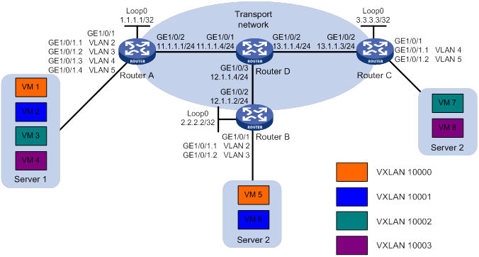
Configuration procedure
1. Configure IP addresses and routing settings:
# Assign IP addresses to interfaces, as shown in Figure 28. (Details not shown.)
# Configure OSPF on all transport network routers (Routers A through D). (Details not shown.)
2. Configure Router A:
# Enable L2VPN.
<RouterA> system-view
[RouterA] l2vpn enable
# Specify VXLAN 11111 as the reserved VXLAN for VXLAN IS-IS.
[RouterA] reserved vxlan 11111
|
|
NOTE: The reserved VXLAN must be the same across VTEPs. |
# Create VSI vpna and VXLAN 10000.
[RouterA] vsi vpna
[RouterA-vsi-vpna] vxlan 10000
[RouterA-vsi-vpna-vxlan-10000] quit
[RouterA-vsi-vpna] quit
# Create VSI vpnb and VXLAN 10001.
[RouterA] vsi vpnb
[RouterA-vsi-vpnb] vxlan 10001
[RouterA-vsi-vpnb-vxlan-10001] quit
[RouterA-vsi-vpnb] quit
# Create VSI vpnc and VXLAN 10002.
[RouterA] vsi vpnc
[RouterA-vsi-vpnc] vxlan 10002
[RouterA-vsi-vpnc-vxlan-10002] quit
[RouterA-vsi-vpnc] quit
# Create VSI vpnd and VXLAN 10003.
[RouterA] vsi vpnd
[RouterA-vsi-vpnd] vxlan 10003
[RouterA-vsi-vpnd-vxlan-10003] quit
[RouterA-vsi-vpnd] quit
# Assign an IP address to Loopback 0. The IP address will be used as the source IP address of the VXLAN tunnels to Router B and Router C.
[RouterA] interface loopback 0
[RouterA-Loopback0] ip address 1.1.1.1 255.255.255.255
[RouterA-Loopback0] quit
# Create a VXLAN tunnel to Router B. The tunnel interface is Tunnel 1. The tunnel destination is Loopback 0 at 2.2.2.2 on Router B.
[RouterA] interface tunnel 1 mode vxlan
[RouterA-Tunnel1] source 1.1.1.1
[RouterA-Tunnel1] destination 2.2.2.2
[RouterA-Tunnel1] quit
# Create a VXLAN tunnel to Router C. The tunnel interface is Tunnel 2. The tunnel destination is Loopback 0 at 3.3.3.3 on Router C.
[RouterA] interface tunnel 2 mode vxlan
[RouterA-Tunnel2] source 1.1.1.1
[RouterA-Tunnel2] destination 3.3.3.3
[RouterA-Tunnel2] quit
# Create GigabitEthernet 1/0/1.1, and configure the subinterface to terminate VLAN 2. Map the subinterface to VSI vpna.
[RouterA] interface gigabitethernet 1/0/1.1
[RouterA-GigabitEthernet1/0/1.1] vlan-type dot1q vid 2
[RouterA-GigabitEthernet1/0/1.1] xconnect vsi vpna
[RouterA-GigabitEthernet1/0/1.1] quit
# Create GigabitEthernet 1/0/1.2, and configure the subinterface to terminate VLAN 3. Map the subinterface to VSI vpnb.
[RouterA] interface gigabitethernet 1/0/1.2
[RouterA-GigabitEthernet1/0/1.2] vlan-type dot1q vid 3
[RouterA-GigabitEthernet1/0/1.2] xconnect vsi vpnb
[RouterA-GigabitEthernet1/0/1.2] quit
# Create GigabitEthernet 1/0/1.3, and configure the subinterface to terminate VLAN 4. Map the subinterface to VSI vpnc.
[RouterA] interface gigabitethernet 1/0/1.3
[RouterA-GigabitEthernet1/0/1.3] vlan-type dot1q vid 4
[RouterA-GigabitEthernet1/0/1.3] xconnect vsi vpnc
[RouterA-GigabitEthernet1/0/1.3] quit
# Create GigabitEthernet 1/0/1.4, and configure the subinterface to terminate VLAN 5. Map the subinterface to VSI vpnd.
[RouterA] interface gigabitethernet 1/0/1.4
[RouterA-GigabitEthernet1/0/1.4] vlan-type dot1q vid 5
[RouterA-GigabitEthernet1/0/1.4] xconnect vsi vpnd
[RouterA-GigabitEthernet1/0/1.4] quit
# Start the VXLAN IS-IS process. Enable VXLAN autonegotiation and MAC advertisement.
[RouterA] vxlan-isis
[RouterA-vxlan-isis] negotiate-vni enable
[RouterA-vxlan-isis] mac-synchronization enable
[RouterA-vxlan-isis] quit
3. Configure Router B:
# Enable L2VPN.
<RouterB> system-view
[RouterB] l2vpn enable
# Specify VXLAN 11111 as the reserved VXLAN for VXLAN IS-IS.
[RouterB] reserved vxlan 11111
# Create VSI vpna and VXLAN 10000.
[RouterB] vsi vpna
[RouterB-vsi-vpna] vxlan 10000
[RouterB-vsi-vpna-vxlan-10000] quit
[RouterB-vsi-vpna] quit
# Create VSI vpnb and VXLAN 10001.
[RouterB] vsi vpnb
[RouterB-vsi-vpnb] vxlan 10001
[RouterB-vsi-vpnb-vxlan-10001] quit
[RouterB-vsi-vpnb] quit
# Assign an IP address to Loopback 0. The IP address will be used as the source IP address of the VXLAN tunnels to Router A and Router C.
[RouterB] interface loopback 0
[RouterB-Loopback0] ip address 2.2.2.2 255.255.255.255
[RouterB-Loopback0] quit
# Create a VXLAN tunnel to Router A.
[RouterB] interface tunnel 1 mode vxlan
[RouterB-Tunnel1] source 2.2.2.2
[RouterB-Tunnel1] destination 1.1.1.1
[RouterB-Tunnel1] quit
# Create a VXLAN tunnel to Router C.
[RouterB] interface tunnel 3 mode vxlan
[RouterB-Tunnel3] source 2.2.2.2
[RouterB-Tunnel3] destination 3.3.3.3
[RouterB-Tunnel3] quit
# Create GigabitEthernet 1/0/1.1, and configure the subinterface to terminate VLAN 2. Map the subinterface to VSI vpna.
[RouterB] interface gigabitethernet 1/0/1.1
[RouterB-GigabitEthernet1/0/1.1] vlan-type dot1q vid 2
[RouterB-GigabitEthernet1/0/1.1] xconnect vsi vpna
[RouterB-GigabitEthernet1/0/1.1] quit
# Create GigabitEthernet 1/0/1.2, and configure the subinterface to terminate VLAN 3. Map the subinterface to VSI vpnb.
[RouterB] interface gigabitethernet 1/0/1.2
[RouterB-GigabitEthernet1/0/1.2] vlan-type dot1q vid 3
[RouterB-GigabitEthernet1/0/1.2] xconnect vsi vpnb
[RouterB-GigabitEthernet1/0/1.2] quit
# Start the VXLAN IS-IS process. Enable VXLAN autonegotiation and MAC advertisement.
[RouterB] vxlan-isis
[RouterB-vxlan-isis] negotiate-vni enable
[RouterB-vxlan-isis] mac-synchronization enable
[RouterB-vxlan-isis] quit
4. Configure Router C:
# Enable L2VPN.
<RouterC> system-view
[RouterC] l2vpn enable
# Specify VXLAN 11111 as the reserved VXLAN for VXLAN IS-IS.
[RouterC] reserved vxlan 11111
# Create VSI vpna and VXLAN 10002.
[RouterC] vsi vpna
[RouterC-vsi-vpna] vxlan 10002
[RouterC-vsi-vpna-vxlan-10002] quit
[RouterC-vsi-vpna] quit
# Create VSI vpnb and VXLAN 10003.
[RouterC] vsi vpnb
[RouterC-vsi-vpnb] vxlan 10003
[RouterC-vsi-vpnb-vxlan-10003] quit
[RouterC-vsi-vpnb] quit
# Assign an IP address to Loopback 0. The IP address will be used as the source IP address of the VXLAN tunnels to Router A and Router B.
[RouterC] interface loopback 0
[RouterC-Loopback0] ip address 3.3.3.3 255.255.255.255
[RouterC-Loopback0] quit
# Create a VXLAN tunnel to Router A.
[RouterC] interface tunnel 2 mode vxlan
[RouterC-Tunnel1] source 3.3.3.3
[RouterC-Tunnel1] destination 1.1.1.1
[RouterC-Tunnel1] quit
# Create a VXLAN tunnel to Router B.
[RouterC] interface tunnel 3 mode vxlan
[RouterC-Tunnel1] source 3.3.3.3
[RouterC-Tunnel1] destination 2.2.2.2
[RouterC-Tunnel1] quit
# Create GigabitEthernet 1/0/1.1, and configure the subinterface to terminate VLAN 4. Map the subinterface to VSI vpna.
[RouterC] interface gigabitethernet 1/0/1.1
[RouterC-GigabitEthernet1/0/1.1] vlan-type dot1q vid 4
[RouterC-GigabitEthernet1/0/1.1] xconnect vsi vpna
[RouterC-GigabitEthernet1/0/1.1] quit
# Create GigabitEthernet 1/0/1.2, and configure the subinterface to terminate VLAN 5. Map the subinterface to VSI vpnb.
[RouterC] interface gigabitethernet 1/0/1.2
[RouterC-GigabitEthernet1/0/1.2] vlan-type dot1q vid 5
[RouterC-GigabitEthernet1/0/1.2] xconnect vsi vpnb
[RouterC-GigabitEthernet1/0/1.2] quit
# Start the VXLAN IS-IS process. Enable VXLAN autonegotiation and MAC advertisement.
[RouterC] vxlan-isis
[RouterC-vxlan-isis] negotiate-vni enable
[RouterC-vxlan-isis] mac-synchronization enable
[RouterC-vxlan-isis] quit
Verifying the configuration
1. Verify the configuration on the VTEPs. This example uses Router A.
# Verify that all VXLAN tunnel interfaces are up.
[RouterA] display interface tunnel
Tunnel1
Current state: UP
Line protocol state: UP
Description: Tunnel1 Interface
Bandwidth: 64 kbps
Maximum transmission unit: 1464
Internet protocol processing: Disabled
Output queue - Urgent queuing: Size/Length/Discards 0/1024/0
Output queue - Protocol queuing: Size/Length/Discards 0/500/0
Output queue - FIFO queuing: Size/Length/Discards 0/75/0
Last clearing of counters: Never
Tunnel source 1.1.1.1, destination 2.2.2.2
Tunnel protocol/transport UDP_VXLAN/IP
Last 300 seconds input rate: 0 bytes/sec, 0 bits/sec, 0 packets/sec
Last 300 seconds output rate: 0 bytes/sec, 0 bits/sec, 0 packets/sec
Input: 0 packets, 0 bytes, 0 drops
Output: 0 packets, 0 bytes, 0 drops
Tunnel2
Current state: UP
Line protocol state: UP
Description: Tunnel2 Interface
Bandwidth: 64 kbps
Maximum transmission unit: 1464
Internet protocol processing: Disabled
Output queue - Urgent queuing: Size/Length/Discards 0/1024/0
Output queue - Protocol queuing: Size/Length/Discards 0/500/0
Output queue - FIFO queuing: Size/Length/Discards 0/75/0
Last clearing of counters: Never
Tunnel source 1.1.1.1, destination 3.3.3.3
Tunnel protocol/transport UDP_VXLAN/IP
Last 300 seconds input rate: 0 bytes/sec, 0 bits/sec, 0 packets/sec
Last 300 seconds output rate: 0 bytes/sec, 0 bits/sec, 0 packets/sec
Input: 0 packets, 0 bytes, 0 drops
Output: 0 packets, 0 bytes, 0 drops
# Verify that the VXLAN tunnels have been assigned to the correct VXLANs.
[RouterA] display l2vpn vsi verbose
VSI Name: vpna
VSI Index : 0
VSI State : Up
MTU : 1500
Bandwidth : -
Broadcast Restrain : -
Multicast Restrain : -
Unknown Unicast Restrain: -
MAC Learning : Enabled
MAC Table Limit : -
Mac Learning rate : -
Drop Unknown : -
Flooding : Enabled
VXLAN ID : 10000
Tunnels:
Tunnel Name Link ID State Type Flood proxy
Tunnel1 0x5000001 UP Auto Disabled
ACs:
AC Link ID State
GE1/0/1.1 0 Up
VSI Name: vpnb
VSI Index : 1
VSI State : Up
MTU : 1500
Bandwidth : -
Broadcast Restrain : -
Multicast Restrain : -
Unknown Unicast Restrain: -
MAC Learning : Enabled
MAC Table Limit : -
Mac Learning rate : -
Drop Unknown : -
Flooding : Enabled
VXLAN ID : 10001
Tunnels:
Tunnel Name Link ID State Type Flood proxy
Tunnel1 0x5000001 UP Auto Disabled
ACs:
AC Link ID State
GE1/0/1.2 0 Up
VSI Name: vpnc
VSI Index : 2
VSI State : Up
MTU : 1500
Bandwidth : -
Broadcast Restrain : -
Multicast Restrain : -
Unknown Unicast Restrain: -
MAC Learning : Enabled
MAC Table Limit : -
Mac Learning rate : -
Drop Unknown : -
Flooding : Enabled
VXLAN ID : 10002
Tunnels:
Tunnel Name Link ID State Type Flood proxy
Tunnel2 0x5000002 UP Auto Disabled
ACs:
AC Link ID State
GE1/0/1.3 0 Up
VSI Name: vpnd
VSI Index : 3
VSI State : Up
MTU : 1500
Bandwidth : -
Broadcast Restrain : -
Multicast Restrain : -
Unknown Unicast Restrain: -
MAC Learning : Enabled
MAC Table Limit : -
Mac Learning rate : -
Drop Unknown : -
Flooding : Enabled
VXLAN ID : 10003
Tunnels:
Tunnel Name Link ID State Type Flood proxy
Tunnel2 0x5000002 UP Auto Disabled
ACs:
AC Link ID State
GE1/0/1.4 0 Up
# Verify that the VTEP has learned the MAC addresses of remote VMs to the VSIs.
[RouterA] display l2vpn mac-address
MAC Address State VSI Name Link ID/Name Aging
0001-0000-001c Dynamic vpna 0 Aging
0002-0000-0009 IS-IS vpna Tunnel1 NotAging
0001-0000-001c Dynamic vpnb 0 Aging
0002-0000-0009 IS-IS vpnb Tunnel1 NotAging
0001-0000-001c Dynamic vpnc 0 Aging
0003-0000-0009 IS-IS vpnc Tunnel2 NotAging
0001-0000-001c Dynamic vpnd 0 Aging
0003-0000-0009 IS-IS vpnd Tunnel2 NotAging
--- 8 mac address(es) found ---
# Verify that the VTEP has established adjacencies with all its neighbors.
[RouterA] display vxlan isis peer
System ID: 0002.0000.0000
Link interface: Tunnel1
Circuit ID: 0002.0000.0000.0001
State: Up
Hold time: 6s
Neighbour DED priority: 64
Uptime: 00:27:44
System ID: 0003.0000.0000
Link interface: Tunnel2
Circuit ID: 0003.0000.0000.0001
State: Up
Hold time: 6s
Neighbour DED priority: 64
Uptime: 00:20:33
# Verify that the VXLAN IS-IS LSDB is populated correctly.
[RouterA] display vxlan isis lsdb
Link state database information for VXLAN ISIS (Tunnel 1)
LSP ID Seq num Checksum Holdtime Length Overload
-----------------------------------------------------------------------------
0001.0000.0000.0000-00* 0x00000006 0x9556 899 97 0
0002.0000.0000.0000-00 0x00000004 0xd3b8 983 89 0
0002.0000.0000.0001-00 0x00000002 0x1471 456 57 0
Link state database information for VXLAN ISIS (Tunnel 2)
LSP ID Seq num Checksum Holdtime Length Overload
-----------------------------------------------------------------------------
0001.0000.0000.0000-00* 0x00000006 0x8462 886 97 0
0003.0000.0000.0000-00 0x00000004 0x730d 1066 89 0
0003.0000.0000.0001-00 0x00000002 0x1b68 809 57 0
Flags: *-Self LSP, +-Self LSP(Extended)
# Verify that VXLAN IS-IS has learned the MAC addresses of remote VMs.
[RouterA] display vxlan isis remote-mac
MAC Flags: A-MAC has been received by an active tunnel interface
C-MAC conflict with local dynamic MAC
F-MAC has been flushed to the remote MAC address table
VXLAN ID: 10000
MAC address: 0002-0000-0009
Interface: Tunnel1
Flags: AF
VXLAN ID: 10001
MAC address: 0002-0000-0009
Interface: Tunnel1
Flags: AF
VXLAN ID: 10002
MAC address: 0003-0000-0009
Interface: Tunnel2
Flags: AF
VXLAN ID: 10003
MAC address: 0003-0000-0009
Interface: Tunnel2
Flags: AF
# Verify that VXLAN IS-IS has learned remote VXLAN information.
[RouterA] display vxlan isis remote-vxlan
VXLAN Flags: S-VXLAN supported at the local end
F-Association between VXLAN and Tunnels has been flushed to L2VPN
VXLAN ID: 10000
Flags: FS
Tunnel: 1
VXLAN ID: 10001
Flags: FS
Tunnel: 1
VXLAN ID: 10002
Flags: FS
Tunnel: 2
VXLAN ID: 10003
Flags: FS
Tunnel: 2
2. Verify that VMs in different sites can ping each other if they are in the same VLAN. VMs cannot ping each other if they are not in the same VLAN. (Details not shown.)
ARP flood suppression,6
Assigning a VXLAN tunnel to a VXLAN,11
Command and hardware compatibility,70
Command and hardware compatibility,9
Command and hardware compatibility,27
Configuration prerequisites,27
Configuration restrictions and guidelines,58
Configuring a centralized VXLAN IP gateway,27
Configuring a centralized VXLAN IP gateway group,28
Configuring a distributed VXLAN IP gateway,29
Configuring a VSI interface,31
Configuring a VXLAN tunnel,10
Configuring ENDP,58
Configuring VXLAN packet check,14
Confining unknown-unicast floods to the local site,13
Creating a VXLAN on a VSI,10
Disabling remote ARP learning for VXLANs,30
Displaying and maintaining ENDP,59
Displaying and maintaining VXLAN IP gateway,31
Displaying and maintaining VXLAN IS-IS,76
Displaying and maintaining VXLANs,15
Enabling ARP flood suppression,15
Enabling host route advertisement through VXLAN IS-IS,71
Enabling host route MAC learning,72
Enabling local-host route proxy,72
Enabling MAC advertisement through VXLAN IS-IS,71
Enabling VXLAN autonegotiation to automate VXLAN tunnel assignment,71
ENDP configuration example,60
Feature and hardware compatibility,1
Managing MAC address entries,12
Mapping a Layer 3 interface to a VSI,12
Overview,21
Overview,57
Protocols and standards,8
Setting the destination UDP port number of VXLAN packets,14
Specifying a reserved VXLAN for VXLAN IS-IS,70
Tuning VXLAN IS-IS parameters,72
Unicast-mode VXLAN configuration example,16
VXLAN configuration task list,9
VXLAN IP gateway configuration examples,32
VXLAN IP gateways,7
VXLAN IS-IS configuration example,77
VXLAN IS-IS configuration task list,70
VXLAN network model,1
VXLAN packet format,2
Working mechanisms,3