- Table of Contents
- Related Documents
-
| Title | Size | Download |
|---|---|---|
| 01-Text | 4.87 MB |
Command and hardware compatibility
Configuring a static ARP entry
Setting the maximum number of dynamic ARP entries for a device
Setting the maximum number of dynamic ARP entries for an interface
Setting the aging timer for dynamic ARP entries
Enabling dynamic ARP entry check
Displaying and maintaining ARP
Long static ARP entry configuration example
Short static ARP entry configuration example
Gratuitous ARP packet learning
Periodic sending of gratuitous ARP packets
Enabling IP conflict notification
Common proxy ARP configuration example
Feature and hardware compatibility
Displaying and maintaining ARP snooping
Feature and hardware compatibility
ARP fast-reply configuration example
Feature and hardware compatibility
Displaying and maintaining ARP PnP
Feature and hardware compatibility
Displaying and maintaining ARP suppression
ARP suppression configuration example
Configuring ARP direct route advertisement
Assigning an IP address to an interface
Displaying and maintaining IP addressing
IP address configuration example
IP unnumbered configuration example
Command and hardware compatibility
Command and hardware compatibility
IP address allocation sequence
DHCP server configuration task list
Configuring an address pool on the DHCP server
Specifying IP address ranges for a DHCP address pool
Specifying gateways for DHCP clients
Specifying a domain name suffix for DHCP clients
Specifying DNS servers for DHCP clients
Specifying WINS servers and NetBIOS node type for DHCP clients
Specifying BIMS server for DHCP clients
Specifying the configuration file for DHCP client auto-configuration
Specifying a server for DHCP clients
Configuring Option 184 parameters for DHCP clients
Configuring the DHCP user class whitelist
Enabling the DHCP server on an interface
Applying an address pool on an interface
Configuring a DHCP policy for dynamic address assignment
Configuring IP address conflict detection
Enabling handling of Option 82
Configuring DHCP server compatibility
Configuring the DHCP server to broadcast all responses
Configure the DHCP server to ignore BOOTP requests
Configuring the DHCP server to send BOOTP responses in RFC 1048 format
Disabling Option 60 encapsulation in DHCP replies
Setting the DSCP value for DHCP packets sent by the DHCP server
Configuring DHCP binding auto backup
Configuring address pool usage alarming
Binding gateways to DHCP server's MAC address
Advertising subnets assigned to clients
Applying a DHCP address pool to a VPN instance
Enabling client offline detection on the DHCP server
Enabling DHCP logging on the DHCP server
Displaying and maintaining the DHCP server
DHCP server configuration examples
Static IP address assignment configuration example
Dynamic IP address assignment configuration example
DHCP user class configuration example
DHCP user class whitelist configuration example
Primary and secondary subnets configuration example
DHCP option customization configuration example
Troubleshooting DHCP server configuration
Failure to obtain a non-conflicting IP address
Configuring the DHCP relay agent
DHCP relay agent support for Option 82
DHCP relay agent configuration task list
Enabling the DHCP relay agent on an interface
Specifying DHCP servers on a relay agent
Specifying the source address and gateway address in DHCP requests
Configuring the DHCP relay agent security features
Enabling the DHCP relay agent to record relay entries
Enabling periodic refresh of dynamic relay entries
Enabling DHCP starvation attack protection
Configuring the DHCP relay agent to release an IP address
Setting the DSCP value for DHCP packets sent by the DHCP relay agent
Enabling DHCP server proxy on a DHCP relay agent
Configuring a DHCP relay address pool
Specifying a gateway address for DHCP clients
Enabling client offline detection on the DHCP relay agent
Configuring the DHCP smart relay feature
Specifying the source IP address for relayed DHCP requests
Configuring the DHCP relay agent to forward DHCP replies based on Option 82
Displaying and maintaining the DHCP relay agent
DHCP relay agent configuration examples
DHCP relay agent configuration example
Option 82 configuration example
Troubleshooting DHCP relay agent configuration
Failure of DHCP clients to obtain configuration parameters through the DHCP relay agent
Enabling the DHCP client on an interface
Configuring a DHCP client ID for an interface
Enabling duplicated address detection
Setting the DSCP value for DHCP packets sent by the DHCP client
Displaying and maintaining the DHCP client
DHCP client configuration example
Application of trusted and untrusted ports
DHCP snooping support for Option 82
Feature and hardware compatibility
DHCP snooping configuration task list
Configuring basic DHCP snooping
Configuring DHCP snooping entry auto backup
Enabling DHCP starvation attack protection
Enabling DHCP-REQUEST attack protection
Setting the maximum number of DHCP snooping entries
Configuring a DHCP packet blocking port
Enabling DHCP snooping logging
Displaying and maintaining DHCP snooping
DHCP snooping configuration examples
Basic DHCP snooping configuration example
Option 82 configuration example
Obtaining an IP address dynamically
Configuring an interface to use BOOTP for IP address acquisition
Displaying and maintaining BOOTP client
BOOTP client configuration example
Dynamic domain name resolution
Feature and hardware compatibility
Configuring the IPv4 DNS client
Configuring static domain name resolution
Configuring dynamic domain name resolution
Configuring the IPv6 DNS client
Configuring static domain name resolution
Configuring dynamic domain name resolution
Configuring network mode tracking for an output interface
Specifying the source interface for DNS packets
Configuring the DNS trusted interface
Setting the DSCP value for outgoing DNS packets
Displaying and maintaining DNS
IPv4 DNS configuration examples
Static domain name resolution configuration example
Dynamic domain name resolution configuration example
DNS proxy configuration example
IPv6 DNS configuration examples
Static domain name resolution configuration example
Dynamic domain name resolution configuration example
DNS proxy configuration example
Troubleshooting IPv4 DNS configuration
Failure to resolve IPv4 addresses
Troubleshooting IPv6 DNS configuration
Failure to resolve IPv6 addresses
Feature and hardware compatibility
DDNS client configuration task list
Applying the DDNS policy to an interface
Setting the DSCP value for outgoing DDNS packets
DDNS configuration example with www.3322.org
DDNS configuration example with PeanutHull server
Command and hardware compatibility
NAT configuration restrictions and guidelines
Configuring outbound one-to-one static NAT
Configuring outbound net-to-net static NAT
Configuring object group-based outbound static NAT
Configuring inbound one-to-one static NAT
Configuring inbound net-to-net static NAT
Configuring object group-based inbound static NAT
Configuration restrictions and guidelines
Configuring outbound dynamic NAT
Configuring inbound dynamic NAT
Configuring load sharing NAT Server
Configuring ACL-based NAT Server
Enabling global mapping sharing for dynamic NAT444
Rearranging NAT rules to adjust their priorities
Changing the priority of an outbound dynamic NAT rule
Changing the priority of an inbound dynamic NAT rule
Changing the priority of a one-to-one mapping rule for inbound static NAT
Changing the priority of a one-to-one mapping rule for outbound static NAT
Changing the priority of a NAT rule for ACL-based NAT Server
Configuring NAT session logging
Configuring NAT444 user logging
Configuring port block usage threshold for dynamic NAT444
Enabling sending ICMP error messages for NAT failures
Enabling NAT reply redirection
Enabling the deletion of timestamps in TCP SYN and SYN ACK packets
Displaying and maintaining NAT
Outbound one-to-one static NAT configuration example
Outbound dynamic NAT configuration example (non-overlapping addresses)
Outbound bidirectional NAT configuration example
NAT Server for external-to-internal access configuration example
NAT Server for external-to-internal access through domain name configuration example
NAT hairpin in C/S mode configuration example
NAT hairpin in P2P mode configuration example
Twice NAT configuration example
Load sharing NAT Server configuration example
NAT DNS mapping configuration example
Static NAT444 configuration example
Dynamic NAT444 configuration example
DS-Lite NAT444 configuration example
Basic IP forwarding on the device
Command and hardware compatibility
Configuring per-packet or per-flow load sharing
Configuring load sharing based on bandwidth
Command and hardware compatibility
Configuring the aging time for fast forwarding entries
Configuring fast forwarding load sharing
Enabling DSCP-based fast forwarding for GRE and VXLAN packet
Displaying and maintaining fast forwarding
Configuring flow classification
Feature and hardware compatibility
Specifying a flow classification policy
Displaying the adjacency table
Feature and hardware compatibility
Command and hardware compatibility
Feature and hardware compatibility
Command and hardware compatibility
Setting TCP MSS for an interface
Configuring TCP path MTU discovery
Enabling sending ICMP error messages
Configuring rate limit for ICMP error messages
Specifying the source address for ICMP packets
Enabling IPv4 local fragment reassembly
Displaying and maintaining IP performance optimization
Feature and hardware compatibility
Configuration restrictions and guidelines
Configuring UDP helper to convert broadcast to unicast
Configuring UDP helper to convert broadcast to multicast
Configuring UDP helper to convert multicast to broadcast or unicast
Displaying and maintaining UDP helper
UDP helper configuration examples
Configuring UDP helper to convert broadcast to unicast
Configuring UDP helper to convert broadcast to multicast
Configuring UDP helper to convert multicast to broadcast
Configuring basic IPv6 settings
Feature and hardware compatibility
Command and hardware compatibility
IPv6 basics configuration task list
Assigning IPv6 addresses to interfaces
Configuring an IPv6 global unicast address
Configuring an IPv6 link-local address
Configuring an IPv6 anycast address
Configuring a static neighbor entry
Setting the maximum number of dynamic neighbor entries
Setting the aging timer for ND entries in stale state
Minimizing link-local ND entries
Configuring parameters for RA messages
Setting the maximum number of attempts to send an NS message for DAD
Configuring IPv6 ND suppression
Configuring IPv6 ND direct route advertisement
Configuring path MTU discovery
Setting a static path MTU for an IPv6 address
Setting the aging time for dynamic path MTUs
Controlling sending ICMPv6 messages
Configuring the rate limit for ICMPv6 error messages
Enabling replying to multicast echo requests
Enabling sending ICMPv6 destination unreachable messages
Enabling sending ICMPv6 time exceeded messages
Enabling sending ICMPv6 redirect messages
Specifying the source address for ICMPv6 packets
Enabling IPv6 local fragment reassembly
Configuring IPv6 load sharing based on bandwidth
Enabling a device to discard IPv6 packets that contain extension headers
Displaying and maintaining IPv6 basics
Basic IPv6 configuration example
IPv6 ND suppression configuration example
Troubleshooting IPv6 basics configuration
DHCPv6 address/prefix assignment
Rapid assignment involving two messages
Assignment involving four messages
Feature and hardware compatibility
Command and hardware compatibility
IPv6 address/prefix allocation sequence
Feature and hardware compatibility
Command and hardware compatibility
Configuring IPv6 prefix assignment
Configuring IPv6 address assignment
Configuring network parameters assignment
Configuring network parameters in a DHCPv6 address pool
Configuring network parameters in a DHCPv6 option group
Configuring a DHCPv6 policy for IPv6 address and prefix assignment
Configuring the DHCPv6 server on an interface
Setting the DSCP value for DHCPv6 packets sent by the DHCPv6 server
Configuring DHCPv6 binding auto backup
Advertising subnets assigned to clients
Applying a DHCPv6 address pool to a VPN instance
Enabling DHCPv6 logging on the DHCPv6 server
Displaying and maintaining the DHCPv6 server
DHCPv6 server configuration examples
Dynamic IPv6 prefix assignment configuration example
Dynamic IPv6 address assignment configuration example
Configuring the DHCPv6 relay agent
Feature and hardware compatibility
Command and hardware compatibility
DHCPv6 relay agent configuration task list
Enabling the DHCPv6 relay agent on an interface
Specifying DHCPv6 servers on the relay agent
Setting the DSCP value for DHCPv6 packets sent by the DHCPv6 relay agent
Specifying a padding mode for the Interface-ID option
Configuring a DHCPv6 relay address pool
Specifying a gateway address for DHCPv6 clients
Displaying and maintaining the DHCPv6 relay agent
DHCPv6 relay agent configuration example
Feature and hardware compatibility
Command and hardware compatibility
Configuration restrictions and guidelines
DHCPv6 client configuration task list
Configuring IPv6 address acquisition
Configuring IPv6 prefix acquisition
Configuring IPv6 address and prefix acquisition
Configuring the DHCPv6 client DUID
Setting the DSCP value for DHCPv6 packets sent by the DHCPv6 client
Displaying and maintaining DHCPv6 client
DHCPv6 client configuration examples
IPv6 address acquisition configuration example
IPv6 prefix acquisition configuration example
IPv6 address and prefix acquisition configuration example
Stateless DHCPv6 configuration example
Application of trusted and untrusted ports
Feature and hardware compatibility
Command and hardware compatibility
H3C implementation of Option 18 and Option 37
DHCPv6 snooping support for Option 37
DHCPv6 snooping configuration task list
Configuring basic DHCPv6 snooping
Configuring Option 18 and Option 37
Configuring DHCPv6 snooping entry auto backup
Setting the maximum number of DHCPv6 snooping entries
Configuring a DHCPv6 packet blocking port
Enabling DHCPv6 snooping logging
Displaying and maintaining DHCPv6 snooping
DHCPv6 snooping configuration example
Configuring IPv6 fast forwarding
Feature and hardware compatibility
Command and hardware compatibility
Configuring the aging time for IPv6 fast forwarding entries
Configuring IPv6 fast forwarding load sharing
Displaying and maintaining IPv6 fast forwarding
Command and hardware compatibility
Tunneling configuration task list
Configuring a tunnel interface
Configuring an IPv6 over IPv4 manual tunnel
Configuration restrictions and guidelines
Configuring an automatic IPv4-compatible IPv6 tunnel
Configuration restrictions and guidelines
Configuration restrictions and guidelines
6to4 tunnel configuration example
6to4 relay configuration example
Configuration restrictions and guidelines
Configuration restrictions and guidelines
6RD tunnel configuration example
6RD relay configuration example
Configuring an IPv4 over IPv4 tunnel
Configuration restrictions and guidelines
Configuring an IPv4 over IPv6 manual tunnel
Configuration restrictions and guidelines
Configuration restrictions and guidelines
Configuring an IPv6 over IPv6 tunnel
Configuration restrictions and guidelines
Displaying and maintaining tunneling configuration
Troubleshooting tunneling configuration
GRE tunnel operating principle
Displaying and maintaining GRE
Configuring an IPv4 over IPv4 GRE tunnel
Configuring an IPv4 over IPv6 GRE tunnel
Feature and hardware compatibility
Feature and hardware compatibility
VAM server configuration task list
Configuring a preshared key for the VAM server
Setting the port number of the VAM server
Specifying authentication and encryption algorithms for the VAM server
Configuring an authentication method
Configuring keepalive parameters
Specifying an ADVPN domain for a VAM client
Configuring a preshared key for a VAM client
Setting the retry interval and retry number for a VAM client
Setting the dumb timer for a VAM client
Configuring a username and password for a VAM client
Configuring an ADVPN tunnel interface
Configuring IPsec for ADVPN tunnels
Displaying and maintaining ADVPN
IPv4 full-mesh ADVPN configuration example
IPv6 full-mesh ADVPN configuration example
IPv4 hub-spoke ADVPN configuration example
IPv6 hub-spoke ADVPN configuration example
IPv4 multi-hub-group ADVPN configuration example
IPv6 multi-hub-group ADVPN configuration example
IPv4 full-mesh NAT traversal ADVPN configuration example
Feature and hardware compatibility
Command and hardware compatibility
Configuring an IPv6-to-IPv4 destination address translation policy
Configuring an IPv6-to-IPv4 source address translation policy
Configuring an IPv4-to-IPv6 destination address translation policy
Configuring an IPv4-to-IPv6 source address translation policy
Setting the ToS field to 0 for translated IPv4 packets
Setting the Traffic Class field to 0 for translated IPv6 packets
Displaying and maintaining AFT
Allowing IPv4 Internet access from an IPv6 network
Providing FTP service from an IPv6 network to the IPv4 Internet
Allowing mutual access between IPv4 and IPv6 networks
Allowing IPv6 Internet access from an IPv4 network
Providing FTP service from an IPv4 network to the IPv6 Internet
Feature and hardware compatibility
Command and hardware compatibility
Configuration restrictions and guidelines
Applying a WAAS policy to an interface
Configuring WAAS to operate in asymmetric mode
Configuring DRE optimization parameters
Configuring the TFO blacklist autodiscovery feature
Restoring predefined WAAS settings
Displaying and maintaining WAAS
Predefined WAAS policy configuration example
User-defined WAAS policy configuration example
Configuring lighttpd Web services
Feature and hardware compatibility
Restrictions and guidelines: lighttpd Web service configuration
Configuring ARP
Overview
ARP resolves IP addresses into MAC addresses on Ethernet networks.
ARP message format
ARP uses two types of messages: ARP request and ARP reply. Figure 1 shows the format of ARP request/reply messages. Numbers in the figure refer to field lengths.
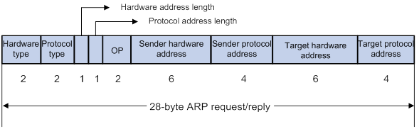
· Hardware type—Hardware address type. The value 1 represents Ethernet.
· Protocol type—Type of the protocol address to be mapped. The hexadecimal value 0x0800 represents IP.
· Hardware address length and protocol address length—Length, in bytes, of a hardware address and a protocol address. For an Ethernet address, the value of the hardware address length field is 6. For an IPv4 address, the value of the protocol address length field is 4.
· OP—Operation code, which describes the type of ARP message. The value 1 represents an ARP request, and the value 2 represents an ARP reply.
· Sender hardware address—Hardware address of the device sending the message.
· Sender protocol address—Protocol address of the device sending the message.
· Target hardware address—Hardware address of the device to which the message is being sent.
· Target protocol address—Protocol address of the device to which the message is being sent.
ARP operating mechanism
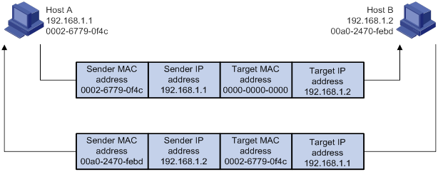
As shown in Figure 2, Host A and Host B are on the same subnet. Host A sends a packet to Host B as follows:
1. Host A looks through the ARP table for an ARP entry for Host B. If one entry is found, Host A uses the MAC address in the entry to encapsulate the IP packet into a data link layer frame. Then Host A sends the frame to Host B.
2. If Host A finds no entry for Host B, Host A buffers the packet and broadcasts an ARP request. The payload of the ARP request contains the following information:
? Sender IP address and sender MAC address—Host A's IP address and MAC address.
? Target IP address—Host B's IP address.
? Target MAC address—An all-zero MAC address.
All hosts on this subnet can receive the broadcast request, but only the requested host (Host B) processes the request.
3. Host B compares its own IP address with the target IP address in the ARP request. If they are the same, Host B operates as follows:
a. Adds the sender IP address and sender MAC address into its ARP table.
b. Encapsulates its MAC address into an ARP reply.
c. Unicasts the ARP reply to Host A.
4. After receiving the ARP reply, Host A operates as follows:
a. Adds the MAC address of Host B into its ARP table.
b. Encapsulates the MAC address into the packet and sends the packet to Host B.
Figure 2 ARP address resolution process
If Host A and Host B are on different subnets, Host A sends a packet to Host B as follows:
5. Host A broadcasts an ARP request where the target IP address is the IP address of the gateway.
6. The gateway responds with its MAC address in an ARP reply to Host A.
7. Host A uses the gateway's MAC address to encapsulate the packet, and then sends the packet to the gateway.
8. If the gateway has an ARP entry for Host B, it forwards the packet to Host B directly. If not, the gateway broadcasts an ARP request, in which the target IP address is the IP address of Host B.
9. After the gateway gets the MAC address of Host B, it sends the packet to Host B.
ARP table
An ARP table stores dynamic, static, OpenFlow, and Rule ARP entries.
Dynamic ARP entry
ARP automatically creates and updates dynamic entries. A dynamic ARP entry is removed when its aging timer expires or the output interface goes down. In addition, a dynamic ARP entry can be overwritten by a static ARP entry.
Static ARP entry
A static ARP entry is manually configured and maintained. It does not age out and cannot be overwritten by any dynamic ARP entry.
Static ARP entries protect communication between devices because attack packets cannot modify the IP-to-MAC mapping in a static ARP entry.
The device supports the following types of static ARP entries:
· Long static ARP entry—It contains the IP address, MAC address, and one of the following combinations:
? VLAN and output interface.
? Receiving and output interfaces.
A long static ARP entry is directly used for forwarding packets.
· Short static ARP entry—It contains only the IP address and MAC address.
? If the output interface is a Layer 3 Ethernet interface, the short ARP entry can be directly used to forward packets.
? If the output interface is a VLAN interface, the device sends an ARP request whose target IP address is the IP address in the short entry. If the sender IP and MAC addresses in the received ARP reply match the short static ARP entry, the device performs the following operations:
- Adds the interface that received the ARP reply to the short static ARP entry.
- Uses the resolved short static ARP entry to forward IP packets.
To communicate with a host by using a fixed IP-to-MAC mapping, configure a short static ARP entry on the device. To communicate with a host by using a fixed IP-to-MAC mapping through an interface in a VLAN, configure a long static ARP entry on the device.
OpenFlow ARP entry
ARP creates OpenFlow ARP entries by learning from the OpenFlow module. An OpenFlow ARP entry does not age out, and it cannot be updated. It can be overwritten by a static ARP entry. An OpenFlow ARP entry can be used directly to forward packets. For more information about OpenFlow, see OpenFlow Configuration Guide.
Rule ARP entry
ARP creates Rule ARP entries by learning from the IPoE, portal, VXLAN, and OVSDB modules. A Rule ARP entry does not age out, and it cannot be updated. It can be overwritten by a static ARP entry. A Rule ARP entry can be used directly to forward packets.
For more information about IPoE, see Layer 2—WAN Access Configuration Guide. For more information about portal, see Security Configuration Guide. For more information about VXLAN and OVSDB, see VXLAN Configuration Guide.
Command and hardware compatibility
Commands and descriptions for centralized devices apply to the following routers:
· MSR810/810-W/810-W-DB/810-LM/810-W-LM/810-10-PoE/810-LM-HK/810-W-LM-HK/810-LMS/810-LUS.
· MSR2600-6-X1/2600-10-X1.
· MSR 2630.
· MSR3600-28/3600-51.
· MSR3600-28-SI/3600-51-SI.
· MSR3610-X1/3610-X1-DP/3610-X1-DC/3610-X1-DP-DC.
· MSR 3610/3620/3620-DP/3640/3660.
· MSR810-LM-GL/810-W-LM-GL/830-6EI-GL/830-10EI-GL/830-6HI-GL/830-10HI-GL/2600-6-X1-GL/3600-28-SI-GL.
Commands and descriptions for distributed devices apply to the following routers:
· MSR5620.
· MSR 5660.
· MSR 5680.
Configuring a static ARP entry
Static ARP entries are effective when the device functions correctly.
A resolved short static ARP entry becomes unresolved upon certain events, for example, when the resolved output interface goes down, or the corresponding VLAN or VLAN interface is deleted.
Long static ARP entries can be effective or ineffective. Ineffective long static ARP entries cannot be used for packet forwarding. A long static ARP entry is ineffective when any of the following conditions exists:
· The corresponding VLAN interface or output interface is down.
· The IP address in the entry conflicts with a local IP address.
· No local interface has an IP address in the same subnet as the IP address in the ARP entry.
A long static ARP entry for a VLAN is deleted if the VLAN, VLAN interface, VSI interface, tunnel interface, or VSI is deleted.
To configure a static ARP entry:
|
Step |
Command |
Remarks |
|
1. Enter system view. |
system-view |
N/A |
|
2. Configure a static ARP entry. |
·
Configure a long static ARP entry: ·
Configure a short static ARP entry: |
By default, no static ARP entries exist. |
Setting the maximum number of dynamic ARP entries for a device
A device can dynamically learn ARP entries. To prevent a device from holding too many ARP entries, you can set the maximum number of dynamic ARP entries that the device can learn. When the maximum number is reached, the device stops learning ARP entries.
If you set a value lower than the number of existing dynamic ARP entries, the device does not remove the existing entries unless they are aged out. You can use the reset arp dynamic command to clear dynamic ARP entries.
To set the maximum number of dynamic ARP entries for a device:
|
Step |
Command |
Remarks |
|
1. Enter system view. |
system-view |
N/A |
|
2. Set the maximum number of dynamic ARP entries for the device. |
·
Centralized devices in standalone mode: ·
Distributed devices in standalone
mode/centralized devices in IRF mode: ·
Distributed devices in IRF mode: |
For information about the default maximum number of dynamic ARP entries for a device, see Layer 3—IP Services Command Reference. To disable the device from learning dynamic ARP entries, set the number to 0. |
Setting the maximum number of dynamic ARP entries for an interface
An interface can dynamically learn ARP entries. To prevent an interface from holding too many ARP entries, you can set the maximum number of dynamic ARP entries that the interface can learn. When the maximum number is reached, the interface stops learning ARP entries.
You can set limits for both a Layer 2 interface and the VLAN interface for a permitted VLAN on the Layer 2 interface. The Layer 2 interface learns an ARP entry only when neither limit is reached.
The total number of dynamic ARP entries that all interfaces learn will not be larger than the maximum number of dynamic ARP entries set for the device.
To set the maximum number of dynamic ARP entries for an interface:
|
Step |
Command |
Remarks |
|
1. Enter system view. |
system-view |
N/A |
|
2. Enter interface view. |
interface interface-type interface-number |
N/A |
|
3. Set the maximum number of dynamic ARP entries for the interface. |
arp max-learning-num max-number |
For information about the default maximum number of dynamic ARP entries for an interface, see Layer 3—IP Services Command Reference. To disable the interface from learning dynamic ARP entries, set the number to 0. |
Setting the aging timer for dynamic ARP entries
Each dynamic ARP entry in the ARP table has a limited lifetime, called an aging timer. The aging timer of a dynamic ARP entry is reset each time the dynamic ARP entry is updated. A dynamic ARP entry that is not updated before its aging timer expires is deleted from the ARP table.
To set the aging timer for dynamic ARP entries:
|
Step |
Command |
Remarks |
|
1. Enter system view. |
system-view |
N/A |
|
2. Set the aging timer for dynamic ARP entries. |
arp timer aging aging-time |
The default setting is 20 minutes. |
Enabling dynamic ARP entry check
The dynamic ARP entry check feature disables the device from supporting dynamic ARP entries that contain multicast MAC addresses. The device cannot learn dynamic ARP entries containing multicast MAC addresses. You cannot manually add static ARP entries containing multicast MAC addresses.
When dynamic ARP entry check is disabled, ARP entries containing multicast MAC addresses are supported. The device can learn dynamic ARP entries containing multicast MAC addresses obtained from the ARP packets sourced from a unicast MAC address. You can also manually add static ARP entries containing multicast MAC addresses.
To enable dynamic ARP entry check:
|
Step |
Command |
Remarks |
|
1. Enter system view. |
system-view |
N/A |
|
2. Enable dynamic ARP entry check. |
arp check enable |
By default, dynamic ARP entry check is enabled. |
Enabling ARP logging
This feature enables a device to log ARP events when ARP cannot resolve IP addresses correctly. The device can log the following ARP events:
· On a proxy ARP-disabled interface, the target IP address of a received ARP packet is not one of the following IP addresses:
? The IP address of the receiving interface.
? The virtual IP address of the VRRP group.
? The public IP address after NAT.
· The sender IP address of a received ARP reply conflicts with one of the following IP addresses:
? The IP address of the receiving interface.
? The virtual IP address of the VRRP group.
? The public IP address after NAT.
The device sends ARP log messages to the information center. You can use the info-center source command to specify the log output rules for the information center. For more information about information center, see Network Management and Monitoring Configuration Guide.
To enable the ARP logging feature:
|
Step |
Command |
Remarks |
|
1. Enter system view. |
system-view |
N/A |
|
2. Enable the ARP logging feature. |
arp check log enable |
By default, ARP logging is disabled. |
Displaying and maintaining ARP
|
|
IMPORTANT: Clearing ARP entries from the ARP table might cause communication failures. Make sure the entries to be cleared do not affect current communications. |
Execute display commands in any view and reset commands in user view.
|
Task |
Command |
|
Display ARP entries (centralized devices in standalone mode). |
display arp [ [ all | dynamic | static ] | vlan vlan-id | interface interface-type interface-number ] [ count | verbose ] |
|
Display ARP entries (distributed devices in standalone mode/centralized devices in IRF mode). |
display arp [ [ all | dynamic | static ] [ slot slot-number ] | vlan vlan-id | interface interface-type interface-number ] [ count | verbose ] |
|
Display ARP entries (distributed devices in IRF mode). |
display arp [ [ all | dynamic | static ] [ chassis chassis-number slot slot-number ] | vlan vlan-id | interface interface-type interface-number ] [ count | verbose ] |
|
Display the ARP entry for an IP address (centralized devices in standalone mode). |
display arp ip-address [ verbose ] |
|
Display the ARP entry for an IP address (distributed devices in standalone mode/centralized devices in IRF mode). |
display arp ip-address [ slot slot-number ] [ verbose ] |
|
Display the ARP entry for an IP address (distributed devices in IRF mode). |
display arp ip-address [ chassis chassis-number slot slot-number ] [ verbose ] |
|
Display the ARP entries for a VPN instance. |
display arp vpn-instance vpn-instance-name [ count ] |
|
Display the aging timer of dynamic ARP entries. |
display arp timer aging |
|
Clear ARP entries from the ARP table (centralized devices in standalone mode). |
reset arp { all | dynamic | interface interface-type interface-number | static } |
|
Clear ARP entries from the ARP table (distributed devices in standalone mode/centralized devices in IRF mode). |
reset arp { all | dynamic | interface interface-type interface-number | slot slot-number | static } |
|
Clear ARP entries from the ARP table (distributed devices in IRF mode). |
reset arp { all | chassis chassis-number slot slot-number | dynamic | interface interface-type interface-number | static } |
Configuration examples
Long static ARP entry configuration example
Network requirements
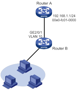
As shown in Figure 3, hosts are connected to Router B. Router B is connected to Router A through GigabitEthernet 2/0/1 in VLAN 10.
To ensure secure communications between Router A and Router B, configure a long static ARP entry for Router A on Router B.
Configuration procedure
# Create VLAN 10.
[RouterB] vlan 10
[RouterB-vlan10] quit
# Add interface GigabitEthernet 2/0/1 to VLAN 10.
[RouterB] interface gigabitethernet 2/0/1
[RouterB-GigabitEthernet2/0/1] port access vlan 10
[RouterB-GigabitEthernet2/0/1] quit
# Create VLAN-interface 10 and configure its IP address.
[RouterB] interface vlan-interface 10
[RouterB-vlan-interface10] ip address 192.168.1.2 8
[RouterB-vlan-interface10] quit
# Configure a long static ARP entry that has IP address 192.168.1.1, MAC address 00e0-fc01-0000, and output interface GigabitEthernet 2/0/1 in VLAN 10.
[RouterB] arp static 192.168.1.1 00e0-fc01-0000 10 gigabitethernet 2/0/1
[RouterB] quit
Verifying the configuration
# Verify that Router B has a long static ARP entry for Router A.
Type: S-Static D-Dynamic O-Openflow R-Rule I-Invalid
IP Address MAC Address SVLAN/VSI Interface/Link ID Aging Type
192.168.1.1 00e0-fc01-0000 10 GE1/0/1 -- S
Short static ARP entry configuration example
Network requirements
As shown in Figure 4, hosts are connected to Router B. Router B is connected to Router A through GigabitEthernet 2/0/2.
To ensure secure communications between the Router A and Router B, configure a short static ARP entry for Router A on Router B.

Configuration procedure
# Configure an IP address for GigabitEthernet 2/0/2.
[RouterB] interface gigabitethernet 2/0/2
[RouterB-GigabitEthernet2/0/2] ip address 192.168.1.2 24
[RouterB-GigabitEthernet2/0/2] quit
# Configure a short static ARP entry that has IP address 192.168.1.1 and MAC address 00e0-fc01-001f.
[RouterB] arp static 192.168.1.1 00e0-fc01-001f
[RouterB] quit
Verifying the configuration
# Verify that Router B has a short static ARP entry for Router A.
Type: S-Static D-Dynamic O-Openflow R-Rule I-Invalid
IP Address MAC Address SVLAN/VSI Interface/Link ID Aging Type
192.168.1.1 00e0-fc01-001f -- -- -- S
Configuring gratuitous ARP
Overview
In a gratuitous ARP packet, the sender IP address and the target IP address are the IP address of the sending device.
A device sends a gratuitous ARP packet for either of the following purposes:
· Determine whether its IP address is already used by another device. If the IP address is already used, the device is informed of the conflict by an ARP reply.
· Inform other devices of a MAC address change.
Gratuitous ARP packet learning
This feature enables a device to create or update ARP entries by using the sender IP and MAC addresses in received gratuitous ARP packets.
When this feature is disabled, the device uses received gratuitous ARP packets to update existing ARP entries only. ARP entries are not created based on the received gratuitous ARP packets, which saves ARP table space.
Periodic sending of gratuitous ARP packets
Enabling periodic sending of gratuitous ARP packets helps downstream devices update ARP entries or MAC entries in a timely manner.
This feature can implement the following functions:
· Prevent gateway spoofing.
Gateway spoofing occurs when an attacker uses the gateway address to send gratuitous ARP packets to the hosts on a network. The traffic destined for the gateway from the hosts is sent to the attacker instead. As a result, the hosts cannot access the external network.
To prevent such gateway spoofing attacks, you can enable the gateway to send gratuitous ARP packets at intervals. Gratuitous ARP packets contain the primary IP address and manually configured secondary IP addresses of the gateway, so hosts can learn correct gateway information.
· Prevent ARP entries from aging out.
If network traffic is heavy or if the host CPU usage is high, received ARP packets can be discarded or are not promptly processed. Eventually, the dynamic ARP entries on the receiving host age out. The traffic between the host and the corresponding devices is interrupted until the host re-creates the ARP entries.
To prevent this problem, you can enable the gateway to send gratuitous ARP packets periodically. Gratuitous ARP packets contain the primary IP address and manually configured secondary IP addresses of the gateway, so the receiving hosts can update ARP entries in a timely manner.
· Prevent the virtual IP address of a VRRP group from being used by a host.
The master router of a VRRP group can periodically send gratuitous ARP packets to the hosts on the local network. The hosts can then update local ARP entries and avoid using the virtual IP address of the VRRP group. The sender MAC address in the gratuitous ARP packet is the virtual MAC address of the virtual router. For more information about VRRP, see High Availability Configuration Guide.
· Update MAC entries of devices in the VLANs having ambiguous Dot1q or QinQ termination configured.
In VRRP configuration, if ambiguous Dot1q or QinQ termination is configured for multiple VLANs and VRRP groups, interfaces configured with VLAN termination must be disabled from transmitting broadcast/multicast packets. Also, a VRRP control VLAN must be configured so that VRRP advertisements can be transmitted within the control VLAN only. In such cases, you can enable periodic sending of gratuitous ARP packets containing the following addresses:
? The VRRP virtual IP address.
? The primary IP address or a manually configured secondary IP address of the sending interface on the subinterfaces.
When a VRRP failover occurs, devices in the VLANs can use the gratuitous ARP packets to update their corresponding MAC entries in a timely manner.
Configuration procedure
When you configure gratuitous ARP, follow these restrictions and guidelines:
· You can enable periodic sending of gratuitous ARP packets on a maximum of 1024 interfaces.
· Periodic sending of gratuitous ARP packets takes effect on an interface only when the following conditions are met:
? The data link layer state of the interface is up.
? The interface has an IP address.
· If you change the sending interval for gratuitous ARP packets, the configuration takes effect at the next sending interval.
· The sending interval for gratuitous ARP packets might be much longer than the specified sending interval in any of the following circumstances:
? This feature is enabled on multiple interfaces.
? Each interface is configured with multiple secondary IP addresses.
? A small sending interval is configured when the previous two conditions exist.
To configure gratuitous ARP:
|
Step |
Command |
Remarks |
|
1. Enter system view. |
system-view |
N/A |
|
2. Enable learning of gratuitous ARP packets. |
gratuitous-arp-learning enable |
By default, learning of gratuitous ARP packets is enabled. |
|
3. Enable the device to send gratuitous ARP packets upon receiving ARP requests whose sender IP address belongs to a different subnet. |
gratuitous-arp-sending enable |
By default, a device does not send gratuitous ARP packets upon receiving ARP requests whose sender IP address belongs to a different subnet. |
|
4. Enter interface view. |
interface interface-type interface-number |
N/A |
|
5. Enable periodic sending of gratuitous ARP packets. |
arp send-gratuitous-arp [ interval interval ] |
By default, periodic sending of gratuitous ARP packets is disabled. |
Enabling IP conflict notification
By default, if the sender IP address of an ARP packet is being used by the receiving device, the receiving device sends a gratuitous ARP request. It also displays an error message after it receives an ARP reply about the conflict.
You can use this command to enable the device to display error messages before sending a gratuitous ARP reply or request for conflict confirmation.
To enable IP conflict notification:
|
Step |
Command |
Remarks |
|
1. Enter system view. |
system-view |
N/A |
|
2. Enable IP conflict notification. |
arp ip-conflict log prompt |
By default, IP conflict notification is disabled. |
Configuring proxy ARP
Proxy ARP enables a device on one network to answer ARP requests for an IP address on another network. With proxy ARP, hosts on different broadcast domains can communicate with each other as they would on the same broadcast domain.
Proxy ARP includes common proxy ARP and local proxy ARP.
· Common proxy ARP—Allows communication between hosts that connect to different Layer 3 interfaces and reside in different broadcast domains.
· Local proxy ARP—Allows communication between hosts that connect to the same Layer 3 interface and reside in different broadcast domains.
Enabling common proxy ARP
|
Step |
Command |
Remarks |
|
1. Enter system view. |
system-view |
N/A |
|
2. Enter interface view. |
interface interface-type interface-number |
The following interface types are supported: · VLAN interface. · Layer 3 Ethernet interface. · Layer 3 Ethernet subinterface. · Layer 3 aggregate interface. · Layer 3 aggregate subinterface. |
|
3. Enable common proxy ARP. |
proxy-arp enable |
By default, common proxy ARP is disabled. |
Enabling local proxy ARP
|
Step |
Command |
Remarks |
|
1. Enter system view. |
system-view |
N/A |
|
2. Enter interface view. |
interface interface-type interface-number |
The following interface types are supported: · VLAN interface. · Layer 3 Ethernet interface. · Layer 3 Ethernet subinterface. · Layer 3 aggregate interface. · Layer 3 aggregate subinterface. |
|
3. Enable local proxy ARP. |
local-proxy-arp enable [ ip-range start-ip-address to end-ip-address ] |
By default, local proxy ARP is disabled. |
Displaying proxy ARP
Execute display commands in any view.
|
Task |
Command |
|
Display common proxy ARP status. |
display proxy-arp [ interface interface-type interface-number ] |
|
Display local proxy ARP status. |
display local-proxy-arp [ interface interface-type interface-number ] |
Common proxy ARP configuration example
Network requirements
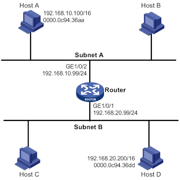
As shown in Figure 5, Host A and Host D have the same prefix and mask, but they are located on different subnets. No default gateway is configured on Host A and Host D.
Configure common proxy ARP on the router to enable communication between Host A and Host D.
Configuration procedure
# Configure the IP address of interface GigabitEthernet 1/0/2.
<Router> system-view
[Router] interface gigabitethernet 1/0/2
[Router-GigabitEthernet1/0/2] ip address 192.168.10.99 255.255.255.0
# Enable common proxy ARP on interface GigabitEthernet 1/0/2.
[Router-GigabitEthernet1/0/2] proxy-arp enable
[Router-GigabitEthernet1/0/2] quit
# Configure the IP address of interface GigabitEthernet 1/0/1.
[Router] interface gigabitethernet 1/0/1
[Router-GigabitEthernet1/0/1] ip address 192.168.20.99 255.255.255.0
# Enable common proxy ARP on interface GigabitEthernet 1/0/1.
[Router-GigabitEthernet1/0/1] proxy-arp enable
[Router-GigabitEthernet1/0/1] quit
Verifying the configuration
# Verify that Host A and Host D can ping each other.
Configuring ARP snooping
This feature is supported only on the following ports:
· Layer 2 Ethernet ports on Ethernet switching modules.
· Fixed Layer 2 Ethernet ports of MSR3600-28 and MSR3600-51 routers.
Overview
ARP snooping is used in Layer 2 switching networks. It creates ARP snooping entries by using information in ARP packets. ARP fast-reply can use the ARP snooping entries.
If you enable ARP snooping for a VLAN, ARP packets received in the VLAN are redirected to the CPU. The CPU uses the sender IP and MAC addresses of the ARP packets, and receiving VLAN and port to create ARP snooping entries.
The aging timer and valid period of an ARP snooping entry are 25 minutes and 15 minutes. If an ARP snooping entry is not updated in 12 minutes, the device sends an ARP request. The ARP request uses the IP address of the entry as the target IP address. If an ARP snooping entry is not updated in 15 minutes, it becomes invalid and cannot be used. After that, if an ARP packet matching the entry is received, the entry becomes valid, and its aging timer restarts. If the aging timer of an ARP snooping entry expires, the entry is removed.
An attack occurs if an ARP packet has the same sender IP address as a valid ARP snooping entry but a different sender MAC address. The ARP snooping entry becomes invalid, and it is removed in 1 minute.
Feature and hardware compatibility
|
Hardware |
ARP snooping compatibility |
|
MSR810/810-W/810-W-DB/810-LM/810-W-LM/810-10-PoE/810-LM-HK/810-W-LM-HK |
Yes |
|
MSR810-LMS/810-LUS |
No |
|
MSR2600-6-X1/2600-10-X1 |
Yes |
|
MSR 2630 |
Yes |
|
MSR3600-28/3600-51 |
Yes |
|
MSR3600-28-SI/3600-51-SI |
Yes |
|
MSR3610-X1/3610-X1-DP/3610-X1-DC/3610-X1-DP-DC |
Yes |
|
MSR 3610/3620/3620-DP/3640/3660 |
Yes |
|
MSR5620/5660/5680 |
Yes |
|
Hardware |
ARP snooping compatibility |
|
MSR810-LM-GL |
Yes |
|
MSR810-W-LM-GL |
Yes |
|
MSR830-6EI-GL |
No |
|
MSR830-10EI-GL |
No |
|
MSR830-6HI-GL |
No |
|
MSR830-10HI-GL |
No |
|
MSR2600-6-X1-GL |
Yes |
|
MSR3600-28-SI-GL |
Yes |
Configuration procedure
To enable ARP snooping for a VLAN:
|
Step |
Command |
Remarks |
|
1. Enter system view. |
system-view |
N/A |
|
2. Enter VLAN view. |
vlan vlan-id |
N/A |
|
3. Enable ARP snooping |
arp snooping enable |
By default, ARP snooping is disabled. |
Displaying and maintaining ARP snooping
Execute display commands in any view and reset commands in user view.
|
Task |
Command |
|
Display ARP snooping entries (centralized devices in standalone mode). |
display arp snooping [ vlan vlan-id ] [ count ] display arp snooping ip ip-address |
|
Display ARP snooping entries (distributed devices in standalone mode/centralized devices in IRF mode). |
display arp snooping [ vlan vlan-id ] [ slot slot-number ] [ count ] display arp snooping ip ip-address [ slot slot-number ] |
|
Display ARP snooping entries (distributed devices in IRF mode). |
display arp snooping [ vlan vlan-id ] [ chassis chassis-number slot slot-number ] [ count ] display arp snooping ip ip-address [ chassis chassis-number slot slot-number ] |
|
Remove ARP snooping entries. |
reset arp snooping [ ip ip-address | vlan vlan-id ] |
Configuring ARP fast-reply
Overview
ARP fast-reply enables a device to directly answer ARP requests according to DHCP snooping entries or ARP snooping entries. ARP fast-reply functions in a VLAN. For information about DHCP snooping, see "Configuring DHCP snooping."
If the target IP address of a received ARP request is the IP address of the VLAN interface, the device delivers the request to the ARP module. If not, the device takes the following steps to process the packet:
1. Search the DHCP snooping table for a match by using the target IP address.
2. If a match is found, whether the device returns a reply depends on the type of interface in the matching entry.
? If the interface is the Ethernet interface that received the ARP request, the device does not return any reply.
? If the interface is a wireless interface or an Ethernet interface other than the receiving interface, the device returns a reply according to the matching entry.
3. If no matching DHCP snooping entry is found and ARP snooping is enabled, the device searches the ARP snooping table.
? If the interface in the matching entry is the Ethernet interface that received the ARP request, the device does not return any reply.
? If the interface is a wireless interface or an Ethernet interface other than the receiving interface, the device returns a reply according to the ARP snooping entry.
4. If no match is found in both tables, the ARP request is forwarded to other interfaces except the receiving interface in the VLAN, or delivered to other modules.
Feature and hardware compatibility
|
Hardware |
ARP fast-reply compatibility |
|
MSR810/810-W/810-W-DB/810-LM/810-W-LM/810-10-PoE/810-LM-HK/810-W-LM-HK/810-LMS/810-LUS |
No |
|
MSR2600-6-X1/2600-10-X1 |
Yes |
|
MSR 2630 |
Yes |
|
MSR3600-28/3600-51 |
Yes |
|
MSR3600-28-SI/3600-51-SI |
No |
|
MSR3610-X1/3610-X1-DP/3610-X1-DC/3610-X1-DP-DC |
Yes |
|
MSR 3610/3620/3620-DP/3640/3660 |
Yes |
|
MSR5620/5660/5680 |
Yes |
|
Hardware |
ARP fast-reply compatibility |
|
MSR810-LM-GL |
No |
|
MSR810-W-LM-GL |
No |
|
MSR830-6EI-GL |
No |
|
MSR830-10EI-GL |
No |
|
MSR830-6HI-GL |
No |
|
MSR830-10HI-GL |
No |
|
MSR2600-6-X1-GL |
Yes |
|
MSR3600-28-SI-GL |
No |
Configuration procedure
To improve the availability of ARP fast-reply, enable ARP snooping at the same time.
To configure ARP fast-reply:
|
Step |
Command |
Remarks |
|
1. Enter system view. |
system-view |
N/A |
|
2. Enter VLAN view. |
vlan vlan-id |
N/A |
|
3. Enable ARP fast-reply. |
arp fast-reply enable |
By default, ARP fast-reply is disabled. |
ARP fast-reply configuration example
Network requirements
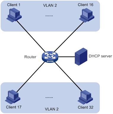
As shown in Figure 6, all clients are in VLAN 2, and access the network through the router. They have obtained IP addresses through DHCP.
Enable ARP snooping and ARP fast-reply for VLAN 2. The router directly returns an ARP reply without broadcasting received ARP requests in the VLAN.
Configuration procedure
# Enable ARP snooping for VLAN 2 on the router.
<Router> system-view
[Router] vlan 2
[Router-vlan2] arp snooping enable
# Enable ARP fast-reply for VLAN 2 on the router.
[Router-vlan2] arp fast-reply enable
[Router-vlan2] quit
Configuring ARP PnP
Overview
The ARP plug and play (PnP) feature is typically configured on a gateway. This feature allows end users to access the gateway without changing their IP addresses on subnets different from the subnet where the gateway resides.
After ARP PnP is enabled on an interface, it provides the following functions:
· ARP PnP enables the interface to always reply to users' ARP requests with the interface's MAC address.
· Upon receiving a packet from the user, ARP PnP replaces the source IP address of the packet with an agent IP address. The agent IP address is on the same subnet as the interface IP address.
· Upon receiving the return packet destined to the agent IP address, ARP PnP replaces the agent IP with the user's original IP address.
Feature and hardware compatibility
|
Hardware |
ARP PnP compatibility |
|
MSR810/810-W/810-W-DB/810-LM/810-W-LM/810-10-PoE/810-LM-HK/810-W-LM-HK |
No |
|
MSR810-LMS/810-LUS |
Yes |
|
MSR2600-6-X1/2600-10-X1 |
Yes |
|
MSR 2630 |
Yes |
|
MSR3600-28/3600-51 |
Yes |
|
MSR3600-28-SI/3600-51-SI |
Yes |
|
MSR3610-X1/3610-X1-DP/3610-X1-DC/3610-X1-DP-DC |
Yes |
|
MSR 3610/3620/3620-DP/3640/3660 |
Yes |
|
MSR5620/5660/5680 |
Yes |
|
Hardware |
ARP PnP compatibility |
|
MSR810-LM-GL |
No |
|
MSR810-W-LM-GL |
No |
|
MSR830-6EI-GL |
Yes |
|
MSR830-10EI-GL |
Yes |
|
MSR830-6HI-GL |
Yes |
|
MSR830-10HI-GL |
Yes |
|
MSR2600-6-X1-GL |
Yes |
|
MSR3600-28-SI-GL |
Yes |
Configuration prerequisites
Before you configure the ARP PnP feature on an interface, perform the following tasks:
· Assign the interface a primary IP address. ARP PnP generates agent IP addresses based on the primary IP address and mask length of the interface.
· Use the reset arp command to delete all ARP entries on the interface.
· Configure NAT on the interface that connects to the external network. For more information about NAT, see "Configuring NAT."
Configuration procedure
|
Step |
Command |
Remarks |
|
1. Enter system view. |
system-view |
N/A |
|
2. Configure an address group and enter its view. |
nat address-group group-number |
By default, no address group exists. |
|
3. Add an IP address range to the address group. |
address start-address end-address |
By default, an address group has no IP address range. You can add multiple IP address ranges to an address group. The IP address ranges must not overlap. |
|
4. Enter interface view of the interface that connects to the external network. |
interface interface-type interface-number |
The following interface types are supported: · Layer 3 Ethernet interfaces. · Layer 3 Ethernet subinterfaces. |
|
5. Configure outbound dynamic NAT. |
nat outbound address-group group-number |
By default, outbound dynamic NAT is not configured. |
|
6. Return to system view. |
quit |
N/A |
|
7. Enter interface view of the interface that connects to the internal network. |
interface interface-type interface-number |
The following interface types are supported: · Layer 3 Ethernet interfaces. · Layer 3 Ethernet subinterfaces. |
|
8. Enable the ARP PnP feature. |
arp pnp |
By default, the ARP PnP feature is disabled. |
Displaying and maintaining ARP PnP
Execute display commands in any view.
|
Task |
Command |
|
Display ARP PnP mappings. |
display arp pnp [ interface interface-type interface-number ] |
ARP PnP configuration example
Network requirements
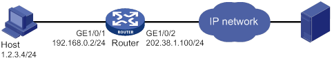
As shown in Figure 7, configure the ARP PnP feature to allow the host at 1.2.3.4 to access the external server through GigabitEthernet 1/0/1.
Configuration procedure
1. Configure NAT:
# Specify IP addresses for GigabitEthernet 1/0/1 and GigabitEthernet 1/0/2.
<Router> system-view
[Router] interface gigabitethernet 1/0/1
[Router-GigabitEthernet1/0/1] ip address 192.168.0.2 24
[Router-GigabitEthernet1/0/1] quit
[Router] interface gigabitethernet 1/0/2
[Router-GigabitEthernet1/0/2] ip address 202.38.1.100 24
[Router-GigabitEthernet1/0/2] quit
# Configure ACL 2000 to identify packets from subnet 192.168.0.0/24.
[Router] acl basic 2000
[Router-acl-ipv4-basic-2000] rule permit source 192.168.0.0 0.0.0.255
[Router-acl-ipv4-basic-2000] quit
# Create address group 1, and add address 202.38.1.100 to the group.
[Router] nat address-group 1
[Router-nat-address-group-1] address 202.38.1.100 202.38.1.100
[Router-nat-address-group-1] quit
# Enable outbound PAT on interface GigabitEthernet 1/0/2 to translate the source address of outgoing packets matching ACL 2000 into the address in address group 1.
[Router] interface gigabitethernet 1/0/2
[Router-GigabitEthernet1/0/2] nat outbound 2000 address-group 1
2. Enable the ARP PnP feature on GigabitEthernet 1/0/1.
[Router] interface gigabitethernet 1/0/1
[Router-GigabitEthernet1/0/1] arp pnp
[Router-GigabitEthernet1/0/1] quit
Verifying the configuration
# Verify that the router creates an ARP PnP mapping for the host IP address 1.2.3.4 on GigabitEthernet 1/0/1.
[Router] display arp pnp interface gigabitethernet 1/0/1
Total number of entries : 1
Agent IP address User IP address MAC address Interface Aging
192.168.0.3 1.2.3.4 00e0-fc00-0001 GE1/0/1 10
Configuring ARP suppression
Overview
The ARP suppression feature enables a device to directly answer ARP requests by using ARP suppression entries. The device generates ARP suppression entries based on dynamic ARP entries that it learns. This feature is typically configured on the PEs connected to base stations in an MPLS L2VPN that provides access to an L3VPN network.
You can also configure the ARP suppression push feature to push ARP suppression entries by broadcasting gratuitous ARP packets.
Figure 8 shows a typical application scenario. ARP suppression is enabled on the PE that connects to the base station. The PE generates ARP suppression entries for the base station, PE-agg 1, and PE-agg 2, and it directly replies subsequent ARP requests for these devices.

Feature and hardware compatibility
|
Hardware |
ARP suppression compatibility |
|
MSR810/810-W/810-W-DB/810-LM/810-W-LM/810-10-PoE/810-LM-HK/810-W-LM-HK |
Yes |
|
MSR810-LMS/810-LUS |
No |
|
MSR2600-6-X1/2600-10-X1 |
Yes |
|
MSR 2630 |
Yes |
|
MSR3600-28/3600-51 |
Yes |
|
MSR3600-28-SI/3600-51-SI |
No |
|
MSR3610-X1/3610-X1-DP/3610-X1-DC/3610-X1-DP-DC |
Yes |
|
MSR 3610/3620/3620-DP/3640/3660 |
Yes |
|
MSR5620/5660/5680 |
Yes |
|
Hardware |
ARP suppression compatibility |
|
MSR810-LM-GL |
Yes |
|
MSR810-W-LM-GL |
Yes |
|
MSR830-6EI-GL |
Yes |
|
MSR830-10EI-GL |
Yes |
|
MSR830-6HI-GL |
No |
|
MSR830-10HI-GL |
Yes |
|
MSR2600-6-X1-GL |
Yes |
|
MSR3600-28-SI-GL |
No |
Configuration procedure
|
Step |
Command |
Remarks |
|
1. Enter system view. |
system-view |
N/A |
|
2. Create a cross-connect group and enter its view. |
xconnect-group group-name |
By default, no cross-connect groups exist. For more information about this command, see MPLS Command Reference. |
|
3. Create a cross-connect and enter its view. |
connection connection-name |
By default, no cross-connects exist. For more information about this command, see MPLS Command Reference. |
|
4. Enable ARP suppression. |
arp suppression enable |
By default, ARP suppression is disabled. |
|
5. Return to cross-connect group view. |
quit |
N/A |
|
6. Return to system view. |
quit |
N/A |
|
7. (Optional.) Enable the ARP suppression push feature and set a push interval. |
arp suppression push interval interval |
By default, the ARP suppression push feature is disabled. |
Displaying and maintaining ARP suppression
Execute display commands in any view and reset commands in user view.
|
Task |
Command |
|
Display ARP suppression entries (centralized devices in standalone mode). |
display arp suppression xconnect-group [ name group-name ] [ count ] |
|
Display ARP suppression entries (distributed devices in standalone mode/centralized devices in IRF mode). |
display arp suppression xconnect-group [ name group-name ] [ slot slot-number ] [ count ] |
|
Display ARP suppression entries (distributed devices in IRF mode). |
display arp suppression xconnect-group [ name group-name ] [ chassis chassis-number slot slot-number ] [ count ] |
|
Clear dynamic ARP suppression entries (centralized devices in standalone mode). |
reset arp suppression xconnect-group |
|
Clear dynamic ARP suppression entries (distributed devices in standalone mode/centralized devices in IRF mode). |
reset arp suppression xconnect-group [ name group-name ] [ slot slot-number ] |
|
Clear dynamic ARP suppression entries (distributed devices in IRF mode). |
reset arp suppression xconnect-group [ name group-name ] [ chassis chassis-number slot slot-number ] |
ARP suppression configuration example
Network requirements
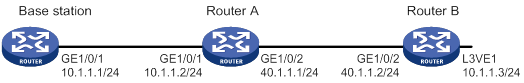
As shown in Figure 9, the base station, Router A, and Router B are in an MPLS L2VPN.
Enable ARP suppression on Router A to directly reply to ARP requests for Router B.
Configuration procedure
1. Configure IP addresses for the interfaces, and make sure the base station can reach the L3VE interface VE-L3VPN 1 of Router B. (Details not shown.)
2. Configure ARP suppression on Router A:
# Create a cross-connect group named vpna and create a cross-connect named svc in the group.
<RouterA> system-view
[RouterA] xconnect-group vpna
[RouterA-xcg-vpna] connection svc
# Enable ARP suppression for the cross-connect svc in cross-connect group vpna.
[RouterA-xcg-vpna-svc] arp suppression enable
Verifying the configuration
1. On the base station, clear ARP entries, and ping the L3VE interface VE-L3VPN 1 of Router B. (Details not shown.)
2. Verify that Router A has ARP suppression entries for the base station and Router B.
[RouterA-xcg-vpna-svc] display arp suppression xconnect-group
IP address MAC address Xconnect-group Connection Aging
10.1.1.1 00e0-fc04-582c vpna svc 25
10.1.1.3 0023-89b7-0861 vpna svc 25
3. Enable ARP debugging on Router B to verify that Router B does not receive an ARP request from the base station under the following conditions (details not shown):
a. Clear ARP entries on the base station.
b. Ping the L3VE interface VE-L3VPN 1 of Router B from the base station.
Configuring ARP direct route advertisement
Overview
The ARP direct route advertisement feature advertises host routes instead of advertising the network route. This feature is typically configured on PE-aggs to advertise host routes to the connected PEs in the L3VPN.
Figure 10 shows a typical application scenario where the PE in the L3VPN has ECMP routes destined to a base station in the L2VPN. Traffic from the PE in the L3VPN to the base station can be load shared by PE-agg 1 and PE-agg 2. If PE-agg 1 fails, the PE uses the host route through PE-agg 2 to forward traffic.
Configuration procedure
|
Step |
Command |
Remarks |
|
1. Enter system view. |
system-view |
N/A |
|
2. Create an L3VE interface and enter its view. |
interface ve-l3vpn interface-number |
By default, no L3VE interface exists. For more information about this command, see MPLS Command Reference. |
|
3. Enable the ARP direct route advertisement feature. |
arp route-direct advertise |
By default, the ARP direct route advertisement feature is disabled. |
Configuring IP addressing
The IP addresses in this chapter refer to IPv4 addresses unless otherwise specified.
This chapter describes IP addressing basics and manual IP address assignment for interfaces. Dynamic IP address assignment (BOOTP and DHCP) and PPP address negotiation are beyond the scope of this chapter.
Overview
This section describes the IP addressing basics.
IP addressing uses a 32-bit address to identify each host on an IPv4 network. To make addresses easier to read, they are written in dotted decimal notation, each address being four octets in length. For example, address 00001010000000010000000100000001 in binary is written as 10.1.1.1.
IP address classes
Each IP address breaks down into the following sections:
· Net ID—Identifies a network. The first several bits of a net ID, known as the class field or class bits, identify the class of the IP address.
· Host ID—Identifies a host on a network.
IP addresses are divided into five classes, as shown in Figure 11. The shaded areas represent the address class. The first three classes are most commonly used.
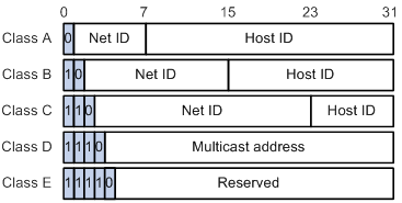
Table 1 IP address classes and ranges
|
Class |
Address range |
Remarks |
|
A |
0.0.0.0 to 127.255.255.255 |
The IP address 0.0.0.0 is used by a host at startup for temporary communication. This address is never a valid destination address. Addresses starting with 127 are reserved for loopback test. Packets destined to these addresses are processed locally as input packets rather than sent to the link. |
|
B |
128.0.0.0 to 191.255.255.255 |
N/A |
|
C |
192.0.0.0 to 223.255.255.255 |
N/A |
|
D |
224.0.0.0 to 239.255.255.255 |
Multicast addresses. |
|
E |
240.0.0.0 to 255.255.255.255 |
Reserved for future use, except for the broadcast address 255.255.255.255. |
Special IP addresses
The following IP addresses are for special use and cannot be used as host IP addresses:
· IP address with an all-zero net ID—Identifies a host on the local network. For example, IP address 0.0.0.16 indicates the host with a host ID of 16 on the local network.
· IP address with an all-zero host ID—Identifies a network.
· IP address with an all-one host ID—Identifies a directed broadcast address. For example, a packet with the destination address of 192.168.1.255 will be broadcast to all the hosts on the network 192.168.1.0.
Subnetting and masking
Subnetting divides a network into smaller networks called subnets by using some bits of the host ID to create a subnet ID.
Masking identifies the boundary between the host ID and the combination of net ID and subnet ID.
Each subnet mask comprises 32 bits that correspond to the bits in an IP address. In a subnet mask, consecutive ones represent the net ID and subnet ID, and consecutive zeros represent the host ID.
Before being subnetted, Class A, B, and C networks use these default masks (also called natural masks): 255.0.0.0, 255.255.0.0, and 255.255.255.0, respectively.
Figure 12 Subnetting a Class B network
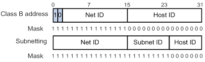
Subnetting increases the number of addresses that cannot be assigned to hosts. Therefore, using subnets means accommodating fewer hosts.
For example, a Class B network without subnetting can accommodate 1022 more hosts than the same network subnetted into 512 subnets.
· Without subnetting—65534 (216 – 2) hosts. (The two deducted addresses are the broadcast address, which has an all-one host ID, and the network address, which has an all-zero host ID.)
· With subnetting—Using the first nine bits of the host-id for subnetting provides 512 (29) subnets. However, only seven bits remain available for the host ID. This allows 126 (27 – 2) hosts in each subnet, a total of 64512 (512 × 126) hosts.
Assigning an IP address to an interface
An interface must have an IP address to communicate with other hosts. You can either manually assign an IP address to an interface, or configure the interface to obtain an IP address through BOOTP, DHCP, or PPP address negotiation. If you change the IP address assignment method, the new IP address will overwrite the previous address.
An interface can have one primary address and multiple secondary addresses.
Typically, you need to configure a primary IP address for an interface. If the interface connects to multiple subnets, configure primary and secondary IP addresses on the interface so the subnets can communicate with each other through the interface.
Configuration guidelines
Follow these guidelines when you assign an IP address to an interface:
· An interface can have only one primary IP address. A newly configured primary IP address overwrites the previous one.
· You cannot assign secondary IP addresses to an interface that obtains an IP address through BOOTP, DHCP, PPP address negotiation, or IP unnumbered.
· The primary and secondary IP addresses assigned to the interface can be located on the same network segment. Different interfaces on your device must reside on different network segments.
· You can assign interfaces IP addresses that have different masks but the same network address if ANDed with the shortest mask. For example, 1.1.1.1/16 and 1.1.2.1/24 have the same network address 1.1.0.0 if ANDed with 255.255.0.0. You can assign the IP addresses to two interfaces on the device. By default, users connected to the two interfaces cannot communicate with each other. For the users to communicate, you must configure common proxy ARP on the device. For more information, see "Configuring proxy ARP."
Configuration procedure
To assign an IP address to an interface:
|
Step |
Command |
Remarks |
|
1. Enter system view. |
system-view |
N/A |
|
2. Enter interface view. |
interface interface-type interface-number |
N/A |
|
3. Assign an IP address to the interface. |
ip address ip-address { mask | mask-length } [ sub ] |
By default, no IP address is assigned to the interface. |
Configuring IP unnumbered
Typically, you assign an IP address to an interface either manually or through DHCP. If the IP addresses are not enough, or the interface is used only occasionally, you can configure an interface to borrow an IP address from other interfaces. This is called IP unnumbered, and the interface borrowing the IP address is called IP unnumbered interface.
You can use IP unnumbered to save IP addresses either when available IP addresses are inadequate or when an interface is brought up only for occasional use.
Configuration guidelines
Follow these guidelines when you configure IP unnumbered:
· Loopback interfaces cannot borrow IP addresses of other interfaces, but other interfaces can borrow IP addresses of loopback interfaces.
· An interface cannot borrow an IP address from an unnumbered interface.
· Multiple interfaces can use the same unnumbered IP address.
· If an interface has multiple manually configured IP addresses, only the manually configured primary IP address can be borrowed.
Configuration prerequisites
Assign an IP address to the interface from which you want to borrow the IP address. Alternatively, you can configure the interface to obtain one through BOOTP, DHCP, or PPP address negotiation.
Configuration procedure
To configure IP unnumbered on an interface:
|
Step |
Command |
Remarks |
|
1. Enter system view. |
system-view |
N/A |
|
2. Enter interface view. |
interface interface-type interface-number |
N/A |
|
3. Specify the interface to borrow the IP address of the specified interface. |
ip address unnumbered interface interface-type interface-number |
By default, the interface does not borrow IP addresses from other interfaces. |
A dynamic routing protocol cannot be enabled on the interface where IP unnumbered is configured. To enable the interface to communicate with other devices, configure a static route to the peer device on the interface. For more configuration information, see "IP unnumbered configuration example."
Displaying and maintaining IP addressing
Execute display commands in any view.
|
Task |
Command |
|
Display IP configuration and statistics for the specified or all Layer 3 interfaces. |
display ip interface [ interface-type interface-number ] |
|
Display brief IP configuration for Layer 3 interfaces. |
display ip interface [ interface-type [ interface-number ] ] brief [ description ] |
Configuration examples
IP address configuration example
Network requirements
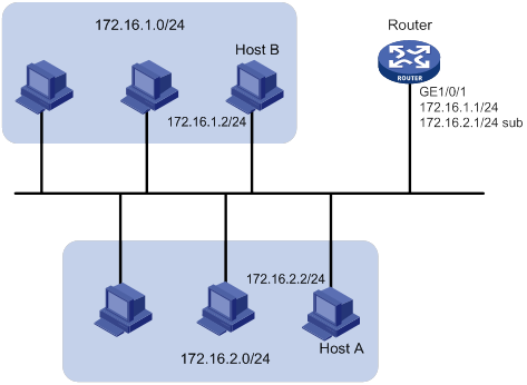
As shown in Figure 13, GigabitEthernet 1/0/1 on the router is connected to a LAN comprising two segments: 172.16.1.0/24 and 172.16.2.0/24.
To enable the hosts on the two network segments to communicate with the external network through the router, and to enable the hosts on the LAN to communicate with each other:
· Assign a primary IP address and a secondary IP address to GigabitEthernet 1/1 on the router.
· Set the primary IP address of the router as the gateway address of the PCs on subnet 172.16.1.0/24. Set the secondary IP address of the router as the gateway address of the PCs on subnet 172.16.2.0/24.
Configuration procedure
# Assign a primary IP address and a secondary IP address to GigabitEthernet 1/0/1.
<Router> system-view
[Router] interface gigabitethernet 1/0/1
[Router-GigabitEthernet1/0/1] ip address 172.16.1.1 255.255.255.0
[Router-GigabitEthernet1/0/1] ip address 172.16.2.1 255.255.255.0 sub
# Set the gateway address to 172.16.1.1 on the PCs attached to subnet 172.16.1.0/24, and to 172.16.2.1 on the PCs attached to subnet 172.16.2.0/24.
Verifying the configuration
# Verify the connectivity between a host on subnet 172.16.1.0/24 and the router.
<Router> ping 172.16.1.2
Ping 172.16.1.2 (172.16.1.2): 56 data bytes, press CTRL_C to break
56 bytes from 172.16.1.2: icmp_seq=0 ttl=128 time=7.000 ms
56 bytes from 172.16.1.2: icmp_seq=1 ttl=128 time=2.000 ms
56 bytes from 172.16.1.2: icmp_seq=2 ttl=128 time=1.000 ms
56 bytes from 172.16.1.2: icmp_seq=3 ttl=128 time=1.000 ms
56 bytes from 172.16.1.2: icmp_seq=4 ttl=128 time=2.000 ms
--- Ping statistics for 172.16.1.2 ---
5 packet(s) transmitted, 5 packet(s) received, 0.0% packet loss
round-trip min/avg/max/std-dev = 1.000/2.600/7.000/2.245 ms
# Verify the connectivity between a host on subnet 172.16.2.0/24 and the router.
<Router> ping 172.16.2.2
Ping 172.16.2.2 (172.16.2.2): 56 data bytes, press CTRL_C to break
56 bytes from 172.16.2.2: icmp_seq=0 ttl=128 time=2.000 ms
56 bytes from 172.16.2.2: icmp_seq=1 ttl=128 time=7.000 ms
56 bytes from 172.16.2.2: icmp_seq=2 ttl=128 time=1.000 ms
56 bytes from 172.16.2.2: icmp_seq=3 ttl=128 time=2.000 ms
56 bytes from 172.16.2.2: icmp_seq=4 ttl=128 time=1.000 ms
--- Ping statistics for 172.16.2.2 ---
5 packet(s) transmitted, 5 packet(s) received, 0.0% packet loss
round-trip min/avg/max/std-dev = 1.000/2.600/7.000/2.245 ms
# Verify the connectivity between a host on subnet 172.16.1.0/24 and a host on subnet 172.16.2.0/24. The ping operation succeeds.
IP unnumbered configuration example
Network requirements
As shown in Figure 14, two routers on an intranet are connected to each other through GigabitEthernet 1/0/2 across a Digital Data Network. Each router connects to a LAN through GigabitEthernet 1/0/1.
To save IP addresses, configure the serial interfaces to borrow IP addresses from the Ethernet interfaces.
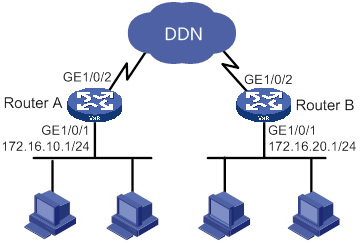
Configuration procedure
1. Configure Router A:
# Assign a primary IP address to GigabitEthernet 1/0/1.
<RouterA> system-view
[RouterA] interface gigabitethernet 1/0/1
[RouterA-GigabitEthernet1/0/1] ip address 172.16.10.1 255.255.255.0
# Configure Router A to generate an ARP entry after GigabitEthernet 1/0/1 receives an LLDP frame that carries a management address TLV.
[RouterA-GigabitEthernet1/0/1] lldp management-address arp-learning
[RouterA-GigabitEthernet1/0/1] quit
# Configure GigabitEthernet 1/0/2 to borrow an IP address from GigabitEthernet 1/0/1.
[RouterA] interface gigabitethernet 1/0/2
[RouterA-GigabitEthernet1/0/2] ip address unnumbered interface gigabitethernet 1/0/1
[RouterA-GigabitEthernet1/0/2] quit
# Configure a static route to the subnet attached to Router B, specifying GigabitEthernet 1/0/2 as the outgoing interface.
[RouterA] ip route-static 172.16.20.0 255.255.255.0 gigabitethernet 1/0/2 172.16.10.10
2. Configure Router B:
# Assign a primary IP address to GigabitEthernet 1/0/1.
<RouterB> system-view
[RouterB] interface gigabitethernet 1/0/1
[RouterB-GigabitEthernet1/0/1] ip address 172.16.20.1 255.255.255.0
# Configure Router B to generate an ARP entry after GigabitEthernet 1/0/1 receives an LLDP frame that carries a management address TLV.
[RouterB-GigabitEthernet1/0/1] lldp management-address arp-learning
[RouterB-GigabitEthernet1/0/1] quit
# Configure interface GigabitEthernet 1/0/2 to borrow an IP address from GigabitEthernet 1/0/1.
[RouterB] interface gigabitethernet 1/0/2
[RouterB-GigabitEthernet1/0/2] ip address unnumbered interface gigabitethernet 1/0/1
[RouterB-GigabitEthernet1/0/2] quit
# Configure a static route to the subnet attached to Router A, specifying GigabitEthernet 1/0/2 as the outgoing interface.
[RouterB] ip route-static 172.16.10.0 255.255.255.0 gigabitethernet 1/0/2 172.16.20.10
Verifying the configuration
# Verify that a host attached to Router B can be pinged from Router A.
[RouterA] ping 172.16.20.2
Ping 172.16.20.2 (172.16.20.2): 56 data bytes, press CTRL_C to break
56 bytes from 172.16.20.2: icmp_seq=0 ttl=128 time=7.000 ms
56 bytes from 172.16.20.2: icmp_seq=1 ttl=128 time=2.000 ms
56 bytes from 172.16.20.2: icmp_seq=2 ttl=128 time=1.000 ms
56 bytes from 172.16.20.2: icmp_seq=3 ttl=128 time=1.000 ms
56 bytes from 172.16.20.2: icmp_seq=4 ttl=128 time=2.000 ms
--- Ping statistics for 172.16.20.2 ---
5 packet(s) transmitted, 5 packet(s) received, 0.0% packet loss
round-trip min/avg/max/std-dev = 1.000/2.600/7.000/2.245 ms
DHCP overview
The Dynamic Host Configuration Protocol (DHCP) provides a framework to assign configuration information to network devices.
Figure 15 shows a typical DHCP application scenario where the DHCP clients and the DHCP server reside on the same subnet. The DHCP clients can also obtain configuration parameters from a DHCP server on another subnet through a DHCP relay agent. For more information about the DHCP relay agent, see "Configuring the DHCP relay agent."
Figure 15 A typical DHCP application
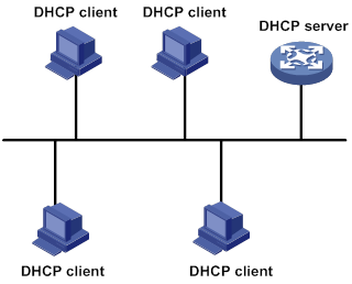
Command and hardware compatibility
Commands and descriptions for centralized devices apply to the following routers:
· MSR810/810-W/810-W-DB/810-LM/810-W-LM/810-10-PoE/810-LM-HK/810-W-LM-HK/810-LMS/810-LUS.
· MSR2600-6-X1/2600-10-X1.
· MSR 2630.
· MSR3600-28/3600-51.
· MSR3600-28-SI/3600-51-SI.
· MSR3610-X1/3610-X1-DP/3610-X1-DC/3610-X1-DP-DC.
· MSR 3610/3620/3620-DP/3640/3660.
· MSR810-LM-GL/810-W-LM-GL/830-6EI-GL/830-10EI-GL/830-6HI-GL/830-10HI-GL/2600-6-X1-GL/3600-28-SI-GL.
Commands and descriptions for distributed devices apply to the following routers:
· MSR5620.
· MSR 5660.
· MSR 5680.
DHCP address allocation
Allocation mechanisms
DHCP supports the following allocation mechanisms:
· Static allocation—The network administrator assigns an IP address to a client, such as a WWW server, and DHCP conveys the assigned address to the client.
· Automatic allocation—DHCP assigns a permanent IP address to a client.
· Dynamic allocation—DHCP assigns an IP address to a client for a limited period of time, which is called a lease. Most DHCP clients obtain their addresses in this way.
IP address allocation process
Figure 16 IP address allocation process
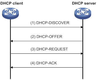
As shown in Figure 16, a DHCP server assigns an IP address to a DHCP client in the following process:
1. The client broadcasts a DHCP-DISCOVER message to locate a DHCP server.
2. Each DHCP server offers configuration parameters such as an IP address to the client in a DHCP-OFFER message. The sending mode of the DHCP-OFFER is determined by the flag field in the DHCP-DISCOVER message. For more information, see "DHCP message format."
3. If the client receives multiple offers, it accepts the first received offer, and broadcasts it in a DHCP-REQUEST message to formally request the IP address. (IP addresses offered by other DHCP servers can be assigned to other clients.)
4. All DHCP servers receive the DHCP-REQUEST message. However, only the server selected by the client does one of the following operations:
? Returns a DHCP-ACK message to confirm that the IP address has been allocated to the client.
? Returns a DHCP-NAK message to deny the IP address allocation.
After receiving the DHCP-ACK message, the client verifies the following details before using the assigned IP address:
· The assigned IP address is not in use. To verify this, the client broadcasts a gratuitous ARP packet. The assigned IP address is not in use if no response is received within the specified time.
· The assigned IP address is not on the same subnet as any IP address in use on the client.
Otherwise, the client sends a DHCP-DECLINE message to the server to request an IP address again.
IP address lease extension
A dynamically assigned IP address has a lease. When the lease expires, the IP address is reclaimed by the DHCP server. To continue using the IP address, the client must extend the lease duration.
When about half of the lease duration elapses, the DHCP client unicasts a DHCP-REQUEST to the DHCP server to extend the lease. Depending on the availability of the IP address, the DHCP server returns one of the following messages:
· A DHCP-ACK unicast confirming that the client's lease duration has been extended.
· A DHCP-NAK unicast denying the request.
If the client receives no reply, it broadcasts another DHCP-REQUEST message for lease extension when about seven-eighths of the lease duration elapses. Again, depending on the availability of the IP address, the DHCP server returns either a DHCP-ACK unicast or a DHCP-NAK unicast.
DHCP message format
Figure 17 shows the DHCP message format. DHCP uses some of the fields in significantly different ways. The numbers in parentheses indicate the size of each field in bytes.
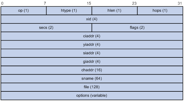
· op—Message type defined in options field. 1 = REQUEST, 2 = REPLY
· htype, hlen—Hardware address type and length of the DHCP client.
· hops—Number of relay agents a request message traveled.
· xid—Transaction ID, a random number chosen by the client to identify an IP address allocation.
· secs—Filled in by the client, the number of seconds elapsed since the client began address acquisition or renewal process. This field is reserved and set to 0.
· flags—The leftmost bit is defined as the BROADCAST (B) flag. If this flag is set to 0, the DHCP server sent a reply back by unicast. If this flag is set to 1, the DHCP server sent a reply back by broadcast. The remaining bits of the flags field are reserved for future use.
· ciaddr—Client IP address if the client has an IP address that is valid and usable. Otherwise, set to zero. (The client does not use this field to request an IP address to lease.)
· yiaddr—Your IP address. It is an IP address assigned by the DHCP server to the DHCP client.
· siaddr—Server IP address, from which the client obtained configuration parameters.
· giaddr—Gateway IP address. It is the IP address of the first relay agent to which a request message travels.
· chaddr—Client hardware address.
· sname—Server host name, from which the client obtained configuration parameters.
· file—Boot file (also called system software image) name and path information, defined by the server to the client.
· options—Optional parameters field that is variable in length. Optional parameters include the message type, lease duration, subnet mask, domain name server IP address, and WINS IP address.
DHCP options
DHCP extends the message format as an extension to BOOTP for compatibility. DHCP uses the options field to carry information for dynamic address allocation and provide additional configuration information for clients.
Figure 18 DHCP option format
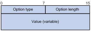
Common DHCP options
The following are common DHCP options:
· Option 3—Router option. It specifies the gateway address.
· Option 6—DNS server option. It specifies the DNS server's IP address.
· Option 33—Static route option. It specifies a list of classful static routes (the destination addresses in these static routes are classful) that a client should add into its routing table. If both Option 33 and Option 121 exist, Option 33 is ignored.
· Option 51—IP address lease option.
· Option 53—DHCP message type option. It identifies the type of the DHCP message.
· Option 55—Parameter request list option. It is used by a DHCP client to request specified configuration parameters. The option includes values that correspond to the parameters requested by the client.
· Option 60—Vendor class identifier option. A DHCP client uses this option to identify its vendor. A DHCP server uses this option to distinguish DHCP clients, and assigns IP addresses to them.
· Option 66—TFTP server name option. It specifies a TFTP server to be assigned to the client.
· Option 67—Boot file name option. It specifies the boot file name to be assigned to the client.
· Option 121—Classless route option. It specifies a list of classless static routes (the destination addresses in these static routes are classless) that a client should add into its routing table. If both Option 33 and Option 121 exist, Option 33 is ignored.
· Option 150—TFTP server IP address option. It specifies the TFTP server IP address to be assigned to the client.
For more information about DHCP options, see RFC 2132 and RFC 3442.
Custom DHCP options
Some options, such as Option 43, Option 82, and Option 184, have no standard definitions in RFC 2132.
Vendor-specific option (Option 43)
DHCP servers and clients use Option 43 to exchange vendor-specific configuration information.
The DHCP client can obtain the following information through Option 43:
· ACS parameters, including the ACS URL, username, and password.
· Service provider identifier, which is acquired by the CPE from the DHCP server and sent to the ACS for selecting vender-specific configurations and parameters. For more information about CPE and ACS, see Network Management and Monitoring Configuration Guide.
· PXE server address, which is used to obtain the boot file or other control information from the PXE server.
· AC address, which is used by an AP to obtain the boot file or other control information from the AC.
1. Format of Option 43:
Figure 19 Option 43 format
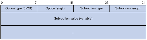
Network configuration parameters are carried in different sub-options of Option 43 as shown in Figure 19.
? Sub-option type—The field value can be 0x01 (ACS parameter sub-option), 0x02 (service provider identifier sub-option), or 0x80 (PXE server address sub-option).
? Sub-option length—Excludes the sub-option type and sub-option length fields.
? Sub-option value—The value format varies by sub-option.
2. Sub-option value field formats:
? ACS parameter sub-option value field—Includes the ACS URL, username, and password separated by spaces (0x20) as shown in Figure 20.
Figure 20 ACS parameter sub-option value field
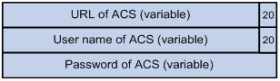
? Service provider identifier sub-option value field—Includes the service provider identifier.
? PXE server address sub-option value field—Includes the PXE server type that can only be 0, the server number that indicates the number of PXE servers contained in the sub-option, and server IP addresses, as shown in Figure 21.
Figure 21 PXE server address sub-option value field
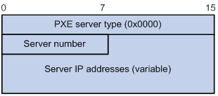
Relay agent option (Option 82)
Option 82 is the relay agent option. It records the location information about the DHCP client. When a DHCP relay agent or DHCP snooping device receives a client's request, it adds Option 82 to the request and sends it to the server.
The administrator can use Option 82 to locate the DHCP client and further implement security control and accounting. The DHCP server can use Option 82 to provide individual configuration policies for the clients.
Option 82 can include a maximum of 255 sub-options and must include a minimum of one sub-option. Option 82 supports two sub-options: sub-option 1 (Circuit ID) and sub-option 2 (Remote ID). Option 82 has no standard definition. Its padding formats vary by vendor.
· Circuit ID has the following padding modes:
? String padding mode—Includes a character string specified by the user.
? Normal padding mode—Includes the VLAN ID and interface number of the interface that receives the client's request.
? Verbose padding mode—Includes the access node identifier specified by the user, and the VLAN ID, interface number and interface type of the interface that receives the client's request.
· Remote ID has the following padding modes:
? String padding mode—Includes a character string specified by the user.
? Normal padding mode—Includes the MAC address of the DHCP relay agent interface or the MAC address of the DHCP snooping device that receives the client's request.
? Sysname padding mode—Includes the device name of the device. To set the device name for the device, use the sysname command in system view.
Option 184
Option 184 is a reserved option. You can define the parameters in the option as needed. The device supports Option 184 carrying voice related parameters, so a DHCP client with voice functions can get voice parameters from the DHCP server.
Option 184 has the following sub-options:
· Sub-option 1—Specifies the IP address of the primary network calling processor. The primary processor acts as the network calling control source and provides program download services. For Option 184, you must define sub-option 1 to make other sub-options take effect.
· Sub-option 2—Specifies the IP address of the backup network calling processor. DHCP clients contact the backup processor when the primary one is unreachable.
· Sub-option 3—Specifies the voice VLAN ID and the result whether the DHCP client takes this VLAN as the voice VLAN.
· Sub-option 4—Specifies the failover route that includes the IP address and the number of the target user. A SIP VoIP user uses this IP address and number to directly establish a connection to the target SIP user when both the primary and backup calling processors are unreachable.
Command and hardware compatibility
Commands and descriptions for centralized devices apply to the following routers:
· MSR810/810-W/810-W-DB/810-LM/810-W-LM/810-10-PoE/810-LM-HK/810-W-LM-HK/810-LMS/810-LUS.
· MSR2600-6-X1/2600-10-X1.
· MSR 2630.
· MSR3600-28/3600-51.
· MSR3600-28-SI/3600-51-SI.
· MSR3610-X1/3610-X1-DP/3610-X1-DC/3610-X1-DP-DC.
· MSR 3610/3620/3620-DP/3640/3660.
Commands and descriptions for distributed devices apply to the following routers:
· MSR5620.
· MSR 5660.
· MSR 5680.
Protocols and standards
· RFC 2131, Dynamic Host Configuration Protocol
· RFC 2132, DHCP Options and BOOTP Vendor Extensions
· RFC 1542, Clarifications and Extensions for the Bootstrap Protocol
· RFC 3046, DHCP Relay Agent Information Option
· RFC 3442, The Classless Static Route Option for Dynamic Host Configuration Protocol (DHCP) version 4
Configuring the DHCP server
Overview
The DHCP server is well suited to networks where:
· Manual configuration and centralized management are difficult to implement.
· IP addresses are limited. For example, an ISP limits the number of concurrent online users, and users must acquire IP addresses dynamically.
· Most hosts do not need fixed IP addresses.
An MCE acting as the DHCP server can assign IP addresses not only to clients on public networks, but also to clients on private networks. The IP address ranges of public and private networks or those of private networks on the DHCP server cannot overlap. For more information about MCE, see MPLS Configuration Guide.
DHCP address pool
Each DHCP address pool has a group of assignable IP addresses and network configuration parameters. The DHCP server selects IP addresses and other parameters from the address pool and assigns them to the DHCP clients.
Address assignment mechanisms
Configure the following address assignment mechanisms as needed:
· Static address allocation—Manually bind the MAC address or ID of a client to an IP address in a DHCP address pool. When the client requests an IP address, the DHCP server assigns the IP address in the static binding to the client.
· Dynamic address allocation—Specify IP address ranges in a DHCP address pool. Upon receiving a DHCP request, the DHCP server dynamically selects an IP address from the matching IP address range in the address pool.
You can specify IP address ranges in an address pool by using either of the following methods:
· Method 1—Specify a primary subnet in an address pool and divide the subnet into multiple address ranges. These address ranges include a common IP address range and IP address ranges for DHCP user classes.
Upon receiving a DHCP request, the DHCP server finds a user class matching the client and selects an IP address in the address range of the user class for the client. A user class can include multiple matching rules, and a client matches the user class as long as it matches any of the rules. In address pool view, you can specify different address ranges for different user classes.
The DHCP server selects an IP address for a client by performing the following steps:
a. DHCP server compares the client against DHCP user classes in the order they are configured.
b. If the client matches a user class, the DHCP server selects an IP address from the address range of the user class.
c. If the matching user class has no assignable addresses, the DHCP server compares the client against the next user class. If all the matching user classes have no assignable addresses, the DHCP server selects an IP address from the common address range.
d. If the DHCP client does not match any DHCP user class, the DHCP server selects an address in the IP address range specified by the address range command. If the address range has no assignable IP addresses or it is not configured, the address allocation fails.
|
|
NOTE: All address ranges must belong to the primary subnet. If an address range does not reside on the primary subnet, DHCP cannot assign the addresses in the address range. |
· Method 2—Specify a primary subnet and multiple secondary subnets in an address pool.
The DHCP server selects an IP address from the primary subnet first. If there is no assignable IP address on the primary subnet, the DHCP server selects an IP address from secondary subnets in the order they are configured.
Principles for selecting an address pool
The DHCP server observes the following principles to select an address pool for a client:
1. If there is an address pool where an IP address is statically bound to the MAC address or ID of the client, the DHCP server selects this address pool and assigns the statically bound IP address and other configuration parameters to the client.
2. If the receiving interface has an address pool applied, the DHCP server selects an IP address and other configuration parameters from this address pool.
3. If no static address pool is configured and no address pool is applied to the receiving interface, the DHCP server selects an address pool depending on the client location.
? Client on the same subnet as the server—The DHCP server compares the IP address of the receiving interface with the primary subnets of all address pools.
- If a match is found, the server selects the address pool with the longest-matching primary subnet.
- If no match is found, the DHCP server compares the IP address with the secondary subnets of all address pools. The server selects the address pool with the longest-matching secondary subnet.
? Client on a different subnet than the server—The DHCP server compares the IP address in the giaddr field of the DHCP request with the primary subnets of all address pools.
- If a match is found, the server selects the address pool with the longest-matching primary subnet.
- If no match is found, the DHCP server compares the IP address with the secondary subnets of all address pools. The server selects the address pool with the longest-matching secondary subnet.
For example, two address pools 1.1.1.0/24 and 1.1.1.0/25 are configured but not applied to any DHCP server's interfaces.
· If the IP address of the receiving interface is 1.1.1.1/25, the DHCP server selects the address pool 1.1.1.0/25. If the address pool has no available IP addresses, the DHCP server will not select the other pool and the address allocation will fail.
· If the IP address of the receiving interface is 1.1.1.130/25, the DHCP server selects the address pool 1.1.1.0/24.
To ensure correct address allocation, keep the IP addresses used for dynamic allocation on one of the subnets:
· Clients on the same subnet as the server—Subnet where the DHCP server receiving interface resides.
· Clients on a different subnet than the server—Subnet where the first DHCP relay interface that faces the clients resides.
|
|
NOTE: As a best practice, configure a minimum of one matching primary subnet in your network. Otherwise, the DHCP server selects only the first matching secondary subnet for address allocation. If the network has more DHCP clients than the assignable IP addresses in the secondary subnet, not all DHCP clients can obtain IP addresses. |
IP address allocation sequence
The DHCP server selects an IP address for a client in the following sequence:
1. IP address statically bound to the client's MAC address or ID.
2. IP address that was ever assigned to the client.
3. IP address designated by the Option 50 field in the DHCP-DISCOVER message sent by the client.
Option 50 is the Requested IP Address option. The client uses this option to specify the wanted IP address in a DHCP-DISCOVER message. The content of Option 50 is user defined.
4. First assignable IP address found in the way discussed in "DHCP address pool."
5. IP address that was a conflict or passed its lease duration. If no IP address is assignable, the server does not respond.
DHCP server configuration task list
|
Tasks at a glance |
|
(Required.) Configuring an address pool on the DHCP server |
|
(Required.) Enabling DHCP |
|
(Required.) Enabling the DHCP server on an interface |
|
(Optional.) Applying an address pool on an interface |
|
(Optional.) Configuring a DHCP policy for dynamic address assignment |
|
(Optional.) Configuring IP address conflict detection |
|
(Optional.) Enabling handling of Option 82 |
|
(Optional.) Configuring DHCP server compatibility |
|
(Optional.) Setting the DSCP value for DHCP packets sent by the DHCP server |
|
(Optional.) Configuring DHCP binding auto backup |
|
(Optional.) Configuring address pool usage alarming |
|
(Optional.) Binding gateways to DHCP server's MAC address |
|
(Optional.) Advertising subnets assigned to clients |
|
(Optional.) Applying a DHCP address pool to a VPN instance |
|
(Optional.) Enabling client offline detection on the DHCP server |
|
(Optional.) Enabling DHCP logging on the DHCP server |
Configuring an address pool on the DHCP server
Configuration task list
Creating a DHCP address pool
|
Step |
Command |
Remarks |
|
1. Enter system view. |
system-view |
N/A |
|
2. Create a DHCP address pool and enter its view. |
dhcp server ip-pool pool-name |
By default, no DHCP address pool exists. |
Specifying IP address ranges for a DHCP address pool
You can configure both static and dynamic address allocation mechanisms in a DHCP address pool. For dynamic address allocation, you can specify either a primary subnet with multiple address ranges or a primary subnet with multiple secondary subnets for a DHCP address pool. You cannot configure both.
Specifying a primary subnet and multiple address ranges for a DHCP address pool
Some scenarios need to classify DHCP clients on the same subnet into different address groups. To meet this need, you can configure DHCP user classes and specify different address ranges for the classes. The clients matching a user class can then get the IP addresses of an address range. In addition, you can specify a common address range for the clients that do not match any user class. If no common address range is specified, such clients fail to obtain IP addresses.
If there is no need to classify clients, you do not need to configure DHCP user classes or their address ranges.
Follow these guidelines when you specify a primary subnet and multiple address ranges for a DHCP address pool:
· If you use the network or address range command multiple times for the same address pool, the most recent configuration takes effect.
· IP addresses specified by the forbidden-ip command are not assignable in the current address pool, but are assignable in other address pools. IP addresses specified by the dhcp server forbidden-ip command are not assignable in any address pool.
To specify a primary subnet and multiple address ranges for a DHCP address pool:
|
Step |
Command |
Remarks |
|
1. Enter system view. |
system-view |
N/A |
|
2. Create a DHCP user class and enter DHCP user class view. |
dhcp class class-name |
Required for client classification. By default, no DHCP user class exists. |
|
3. Configure a match rule for the DHCP user class. |
if-match rule rule-number { hardware-address hardware-address mask hardware-address-mask | option option-code [ ascii ascii-string [ offset offset | partial ] | hex hex-string [ mask mask | offset offset length length | partial ] ] | relay-agent gateway-address } |
Required for client classification. By default, no match rule is configured for a DHCP user class. |
|
4. Return to system view. |
quit |
N/A |
|
5. Create a DHCP address pool and enter its view. |
dhcp server ip-pool pool-name |
By default, no DHCP address pool exists. |
|
6. Specify the primary subnet for the address pool. |
network network-address [ mask-length | mask mask ] |
By default, no primary subnet is specified. |
|
7. (Optional.) Specify the common address range. |
address range start-ip-address [ end-ip-address ] [ vpn-instance vpn-instance-name ] |
By default, no IP address range is specified. |
|
8. (Optional.) Specify an IP address range for a DHCP user class. |
class class-name range start-ip-address end-ip-address |
By default, no IP address range is specified for a user class. The DHCP user class must already exist. To specify address ranges for multiple DHCP user classes, repeat this step. |
|
9. (Optional.) Set the address lease duration. |
expired { day day [ hour hour [ minute minute [ second second ] ] ] | unlimited } |
The default setting is 1 day. |
|
10. (Optional.) Exclude the specified IP addresses in the address pool from dynamic allocation. |
forbidden-ip ip-address&<1-8> |
By default, all the IP addresses in the DHCP address pool are assignable. To exclude multiple address ranges from dynamic allocation, repeat this step. |
|
11. Return to system view. |
quit |
N/A |
|
12. (Optional.) Exclude the specified IP addresses from automatic allocation globally. |
dhcp server forbidden-ip start-ip-address [ end-ip-address ] [ vpn-instance vpn-instance-name ] |
By default, except for the IP address of the DHCP server interface, all IP addresses in address pools are assignable. To exclude multiple IP address ranges, repeat this step. |
Specifying a primary subnet and multiple secondary subnets for a DHCP address pool
If an address pool has a primary subnet and multiple secondary subnets, the server assigns IP addresses on a secondary subnet when the primary subnet has no assignable IP addresses.
Follow these guidelines when you specify a primary subnet and secondary subnets for a DHCP address pool:
· You can specify only one primary subnet in each address pool. If you use the network command multiple times, the most recent configuration takes effect.
· You can specify a maximum of 32 secondary subnets in each address pool.
· IP addresses specified by the forbidden-ip command are not assignable in the current address pool, but are assignable in other address pools. IP addresses specified by the dhcp server forbidden-ip command are not assignable in any address pool.
To specify a primary subnet and secondary subnets for a DHCP address pool:
|
Step |
Command |
Remarks |
|
1. Enter system view. |
system-view |
N/A |
|
2. Create a DHCP address pool and enter its view. |
dhcp server ip-pool pool-name |
By default, no DHCP address pool exists. |
|
3. Specify the primary subnet. |
network network-address [ mask-length | mask mask ] |
By default, no primary subnet is specified. |
|
4. (Optional.) Specify a secondary subnet. |
network network-address [ mask-length | mask mask ] secondary |
By default, no secondary subnet is specified. |
|
5. (Optional.) Return to address pool view. |
quit |
N/A |
|
6. (Optional.) Set the address lease duration. |
expired { day day [ hour hour [ minute minute [ second second ] ] ] | unlimited } |
The default setting is 1 day. |
|
7. (Optional.) Exclude the specified IP addresses from dynamic allocation. |
forbidden-ip ip-address&<1-8> |
By default, all the IP addresses in the DHCP address pool can be dynamically allocated. To exclude multiple address ranges from the address pool, repeat this step. |
|
8. Return to system view. |
quit |
N/A |
|
9. (Optional.) Exclude the specified IP addresses from dynamic allocation globally. |
dhcp server forbidden-ip start-ip-address [ end-ip-address ] [ vpn-instance vpn-instance-name ] |
Except for the IP address of the DHCP server interface, IP addresses in all address pools are assignable by default. To exclude multiple address ranges globally, repeat this step. |
Configuring a static binding in a DHCP address pool
Some DHCP clients, such as a WWW server, need fixed IP addresses. To provide a fixed IP address for a client, you can statically bind the MAC address or ID of the client to an IP address in a DHCP address pool. When the client requests an IP address, the DHCP server assigns the IP address in the static binding to the client.
Follow these guidelines when you configure a static binding:
· One IP address can be bound to only one client MAC or client ID. You cannot modify bindings that have been created. To change the binding for a DHCP client, you must delete the existing binding first.
· The IP address of a static binding cannot be the address of the DHCP server interface. Otherwise, an IP address conflict occurs and the bound client cannot obtain an IP address correctly.
· Multiple interfaces on the same device might all use DHCP to request a static IP address. In this case, use client IDs rather than the device's MAC address to identify the interfaces. Otherwise, IP address allocation will fail.
To configure a static binding:
|
Step |
Command |
Remarks |
|
1. Enter system view. |
system-view |
N/A |
|
2. Create a DHCP address pool and enter its view. |
dhcp server ip-pool pool-name |
By default, no DHCP address pool exists. |
|
3. Configure a static binding. |
static-bind ip-address ip-address [ mask-length | mask mask ] { client-identifier client-identifier | hardware-address hardware-address [ ethernet | token-ring ] } |
By default, no static binding is configured. To add more static bindings, repeat this step. |
|
4. (Optional.) Set the lease duration for the IP address. |
expired { day day [ hour hour [ minute minute [ second second ] ] ] | unlimited } |
The default setting is 1 day. |
Specifying gateways for DHCP clients
DHCP clients send packets destined for other networks to a gateway. The DHCP server can assign the gateway address to the DHCP clients.
You can specify gateway addresses in each address pool on the DHCP server. A maximum of 64 gateways can be specified in DHCP address pool view or secondary subnet view.
The DHCP server assigns gateway addresses to clients on a secondary subnet in the following ways:
· If gateways are specified in both address pool view and secondary subnet view, DHCP assigns those specified in the secondary subnet view.
· If gateways are specified in address pool view but not in secondary subnet view, DHCP assigns those specified in address pool view.
To configure gateways in the DHCP address pool:
|
Step |
Command |
Remarks |
|
1. Enter system view. |
system-view |
N/A |
|
2. Create a DHCP address pool and enter its view. |
dhcp server ip-pool pool-name |
By default, no DHCP address pool exists. |
|
3. Specify gateways. |
gateway-list ip-address&<1-64> |
By default, no gateway is specified. |
|
4. (Optional.) Enter secondary subnet view |
network network-address [ mask-length | mask mask ] secondary |
N/A |
|
5. (Optional.) Specify gateways. |
gateway-list ip-address&<1-64> |
By default, no gateway is specified. |
Specifying a domain name suffix for DHCP clients
You can specify a domain name suffix in a DHCP address pool on the DHCP server. With this suffix assigned, the client only needs to input part of a domain name, and the system adds the domain name suffix for name resolution. For more information about DNS, see "Configuring DNS."
To configure a domain name suffix in the DHCP address pool:
|
Step |
Command |
Remarks |
|
1. Enter system view. |
system-view |
N/A |
|
2. Create a DHCP address pool and enter its view. |
dhcp server ip-pool pool-name |
By default, no DHCP address pool exists. |
|
3. Specify a domain name suffix. |
domain-name domain-name |
By default, no domain name is specified. |
Specifying DNS servers for DHCP clients
To access hosts on the Internet through domain names, a DHCP client must contact a DNS server to resolve names. You can specify up to eight DNS servers in a DHCP address pool.
To specify DNS servers in a DHCP address pool:
|
Step |
Command |
Remarks |
|
1. Enter system view. |
system-view |
N/A |
|
2. Create a DHCP address pool and enter its view. |
dhcp server ip-pool pool-name |
By default, no DHCP address pool exists. |
|
3. Specify DNS servers. |
dns-list ip-address&<1-8> |
By default, no DNS server is specified. |
Specifying WINS servers and NetBIOS node type for DHCP clients
A Microsoft DHCP client using NetBIOS protocol must contact a WINS server for name resolution. You can specify up to eight WINS servers for such clients in a DHCP address pool.
In addition, you must specify a NetBIOS node type for the clients to approach name resolution. There are four NetBIOS node types:
· b (broadcast)-node—A b-node client sends the destination name in a broadcast message. The destination returns its IP address to the client after receiving the message.
· p (peer-to-peer)-node—A p-node client sends the destination name in a unicast message to the WINS server. The WINS server returns the destination IP address.
· m (mixed)-node—An m-node client broadcasts the destination name. If it receives no response, it unicasts the destination name to the WINS server to get the destination IP address.
· h (hybrid)-node—An h-node client unicasts the destination name to the WINS server. If it receives no response, it broadcasts the destination name to get the destination IP address.
To configure WINS servers and NetBIOS node type in a DHCP address pool:
|
Step |
Command |
Remarks |
|
1. Enter system view. |
system-view |
N/A |
|
2. Create a DHCP address pool and enter its view. |
dhcp server ip-pool pool-name |
By default, no DHCP address pool exists. |
|
3. Specify WINS servers. |
nbns-list ip-address&<1-8> |
This step is optional for b-node. By default, no WINS server is specified. |
|
4. Specify the NetBIOS node type. |
netbios-type { b-node | h-node | m-node | p-node } |
By default, no NetBIOS node type is specified. |
Specifying BIMS server for DHCP clients
Perform this task to provide the BIMS server IP address, port number, and shared key for the clients. The DHCP clients contact the BIMS server to get configuration files and perform software upgrade and backup.
To configure the BIMS server IP address, port number, and shared key in the DHCP address pool:
|
Step |
Command |
Remarks |
|
1. Enter system view. |
system-view |
N/A |
|
2. Create a DHCP address pool and enter its view. |
dhcp server ip-pool pool-name |
By default, no DHCP address pool exists. |
|
3. Specify the BIMS server IP address, port number, and shared key. |
bims-server ip ip-address [ port port-number ] sharekey { cipher | simple } string |
By default, no BIMS server information is specified. |
Specifying the configuration file for DHCP client auto-configuration
Auto-configuration enables a device to obtain a set of configuration settings automatically from servers when the device starts up without a configuration file. It requires the cooperation of the DHCP server, HTTP server, DNS server, and TFTP server. For more information about auto-configuration, see Fundamentals Configuration Guide.
Follow these guidelines to specify the parameters on the DHCP server for configuration file acquisition:
· If the configuration file is on a TFTP server, specify the IP address or name of the TFTP server, and the configuration file name.
· If the configuration file is on an HTTP server, specify the configuration file URL.
The DHCP client uses the obtained parameters to contact the TFTP server or the HTTP server to get the configuration file.
To specify the configuration file name in a DHCP address pool:
|
Step |
Command |
Remarks |
|
1. Enter system view. |
system-view |
N/A |
|
2. Create a DHCP address pool and enter its view. |
dhcp server ip-pool pool-name |
By default, no DHCP address pool exists. |
|
3. Specify the IP address or the name of a TFTP server. |
·
Specify the IP address of the TFTP server: ·
Specify the name of the TFTP server: |
You can specify both the IP address and name of the TFTP server. By default, no TFTP server is specified. |
|
4. Specify the configuration file name. |
bootfile-name bootfile-name |
By default, no configuration file name is specified. |
To specify the configuration file URL in a DHCP address pool:
|
Step |
Command |
Remarks |
|
1. Enter system view. |
system-view |
N/A |
|
2. Create a DHCP address pool and enter its view. |
dhcp server ip-pool pool-name |
By default, no DHCP address pool exists. |
|
3. Specify the URL of the configuration file. |
bootfile-name url |
By default, no configuration file URL is specified. |
Specifying a server for DHCP clients
Some DHCP clients need to obtain configuration information from a server, such as a TFTP server. You can specify the IP address of that server. The DHCP server sends the server's IP address to DHCP clients along with other configuration information.
To specify the IP address of a server:
|
Step |
Command |
Remarks |
|
1. Enter system view. |
system-view |
N/A |
|
2. Create a DHCP address pool and enter its view. |
dhcp server ip-pool pool-name |
By default, no DHCP address pool exists. |
|
3. Specify the IP address of a server. |
next-server ip-address |
By default, no server is specified. |
Configuring Option 184 parameters for DHCP clients
To assign calling parameters to DHCP clients with voice service, you must configure Option 184 on the DHCP server. For more information about Option 184, see "Option 184."
To configure option 184 parameters in a DHCP address pool:
|
Step |
Command |
Remarks |
|
1. Enter system view. |
system-view |
N/A |
|
2. Create a DHCP address pool and enter its view. |
dhcp server ip-pool pool-name |
By default, no DHCP address pool exists. |
|
3. Specify the IP address of the primary network calling processor. |
voice-config ncp-ip ip-address |
By default, no primary network calling processor is specified. After you configure this command, the other Option 184 parameters take effect. |
|
4. (Optional.) Specify the IP address for the backup server. |
voice-config as-ip ip-address |
By default, no backup network calling processor is specified. |
|
5. (Optional.) Configure the voice VLAN. |
voice-config voice-vlan vlan-id { disable | enable } |
By default, no voice VLAN is configured. |
|
6. (Optional.) Specify the failover IP address and dialer string. |
voice-config fail-over ip-address dialer-string |
By default, no failover IP address or dialer string is specified. |
Customizing DHCP options
|
|
IMPORTANT: Use caution when customizing DHCP options because the configuration might affect DHCP operation. |
You can customize options for the following purposes:
· Add newly released options.
· Add options for which the vendor defines the contents, for example, Option 43.
· Add options for which the CLI does not provide a dedicated configuration command. For example, you can use the option 4 ip-address 1.1.1.1 command to define the time server address 1.1.1.1 for DHCP clients.
· Add all option values if the actual requirement exceeds the limit for a dedicated option configuration command. For example, the dns-list command can specify up to eight DNS servers. To specify more than eight DNS servers, you must use the option 6 command to define all DNS servers.
To customize a DHCP option in a DHCP address pool:
|
Step |
Command |
Remarks |
|
1. Enter system view. |
system-view |
N/A |
|
2. Create a DHCP address pool and enter its view. |
dhcp server ip-pool pool-name |
By default, no DHCP address pool exists. |
|
3. Customize a DHCP option. |
option code { ascii ascii-string | hex hex-string | ip-address ip-address&<1-8> } |
By default, no DHCP option is customized in a DHCP address pool. DHCP options specified in DHCP option groups take precedence over those specified in DHCP address pools. |
To customize a DHCP option in a DHCP option group:
|
Step |
Command |
Remarks |
|
1. Enter system view. |
system-view |
N/A |
|
2. Create a DHCP user class and enter DHCP user class view. |
dhcp class class-name |
By default, no DHCP user class exists. |
|
3. Configure a match rule for the DHCP user class. |
if-match rule rule-number { hardware-address hardware-address mask hardware-address-mask | option option-code [ ascii ascii-string [ offset offset | partial ] | hex hex-string [ mask mask | offset offset length length | partial ] ] | relay-agent gateway-address } |
By default, no match rule is configured for a DHCP user class. |
|
4. Return to system view. |
quit |
N/A |
|
5. Create a DHCP option group and enter DHCP option group view. |
dhcp option group option-group-number |
By default, no DHCP option group exists. |
|
6. Customize a DHCP option. |
option code { ascii ascii-string | hex hex-string | ip-address ip-address&<1-8> } |
By default, no DHCP option is customized in a DHCP option group. DHCP options specified in DHCP option groups take precedence over those specified in DHCP address pools. |
|
7. Create a DHCP address pool and enter DHCP address pool view. |
dhcp server ip-pool pool-name |
By default, no DHCP address pool exists. |
|
8. Specify the DHCP option group for the DHCP user class. |
class class-name option group option-group-number |
By default, no DHCP option group is specified for a DHCP user class. |
|
Option |
Option name |
Corresponding command |
Recommended option command parameters |
|
3 |
Router Option |
gateway-list |
ip-address |
|
6 |
Domain Name Server Option |
dns-list |
ip-address |
|
15 |
Domain Name |
domain-name |
ascii |
|
44 |
NetBIOS over TCP/IP Name Server Option |
nbns-list |
ip-address |
|
46 |
NetBIOS over TCP/IP Node Type Option |
netbios-type |
hex |
|
66 |
TFTP server name |
tftp-server |
ascii |
|
67 |
Boot file name |
bootfile-name |
ascii |
|
43 |
Vendor Specific Information |
N/A |
hex |
Configuring the DHCP user class whitelist
The DHCP user class whitelist allows the DHCP server to process requests only from clients on the DHCP user class whitelist. The whitelist does not take effect on clients who request static IP addresses, and the server always processes their requests.
To configure the DHCP user class whitelist:
|
Step |
Command |
Remarks |
|
1. Enter system view. |
system-view |
N/A |
|
2. Create a DHCP user class and enter DHCP user class view. |
dhcp class class-name |
By default, no DHCP user class exists. |
|
3. Configure a match rule for the DHCP user class. |
if-match rule rule-number { hardware-address hardware-address mask hardware-address-mask | option option-code [ ascii ascii-string [ offset offset | partial ] | hex hex-string [ mask mask | offset offset length length | partial ] ] | relay-agent gateway-address } |
By default, no match rule is configured for a DHCP user class. |
|
4. Return to system view. |
quit |
N/A |
|
5. Create a DHCP address pool and enter DHCP address pool view. |
dhcp server ip-pool pool-name |
By default, no DHCP address pool exists. |
|
6. Enable the DHCP user class whitelist. |
verify class |
By default, the DHCP user class whitelist is disabled. |
|
7. Add DHCP user classes to the DHCP user class whitelist. |
valid class class-name&<1-8> |
By default, no DHCP user class is on the DHCP user class whitelist. |
Enabling DHCP
You must enable DHCP to validate other DHCP configurations.
To enable DHCP:
|
Step |
Command |
Remarks |
|
1. Enter system view. |
system-view |
N/A |
|
2. Enable DHCP. |
dhcp enable |
By default, DHCP is disabled. |
Enabling the DHCP server on an interface
Perform this task to enable the DHCP server on an interface. Upon receiving a DHCP request on the interface, the DHCP server assigns the client an IP address and other configuration parameters from a DHCP address pool.
To enable the DHCP server on an interface:
|
Step |
Command |
Remarks |
|
1. Enter system view. |
system-view |
N/A |
|
2. Enter interface view. |
interface interface-type interface-number |
N/A |
|
3. Enable the DHCP server on the interface. |
dhcp select server |
By default, the DHCP server on the interface is enabled. |
Applying an address pool on an interface
Perform this task to apply a DHCP address pool on an interface.
Upon receiving a DHCP request from the interface, the DHCP server performs address allocation in the following ways:
· If a static binding is found for the client, the server assigns the static IP address and configuration parameters from the address pool that contains the static binding.
· If no static binding is found for the client, the server uses the address pool applied to the interface for address and configuration parameter allocation.
To apply an address pool on an interface:
|
Step |
Command |
Remarks |
|
1. Enter system view. |
system-view |
N/A |
|
2. Enter interface view. |
interface interface-type interface-number |
N/A |
|
3. Apply an address pool on the interface. |
dhcp server apply ip-pool pool-name |
By default, no address pool is applied on an interface. If the applied address pool does not exist, the DHCP server fails to perform dynamic address allocation. |
Configuring a DHCP policy for dynamic address assignment
In a DHCP policy, each DHCP user class has a bound DHCP address pool. Clients matching different user classes obtain IP addresses and other parameters from different address pools. The DHCP policy must be applied to the interface that acts as the DHCP server. When receiving a DHCP request, the DHCP server compares the packet against the user classes in the order that they are configured.
· If a match is found and the bound address pool has assignable IP addresses, the server assigns an IP address and other parameters from the address pool. If the address pool does not have assignable IP addresses, the address assignment fails.
· If no match is found, the server assigns an IP address and other parameters from the default DHCP address pool. If no default address pool is specified or the default address pool does not have assignable IP addresses, the address assignment fails.
For successful address assignment, make sure the applied DHCP policy and the bound address pools exist.
To configure a DHCP policy for dynamic address assignment:
|
Step |
Command |
Remarks |
|
1. Enter system view. |
system-view |
N/A |
|
2. Create a DHCP user class and enter DHCP user class view. |
dhcp class class-name |
By default, no DHCP user class exists. |
|
3. Configure a match rule for the DHCP user class. |
if-match rule rule-number { hardware-address hardware-address mask hardware-address-mask | option option-code [ ascii ascii-string [ offset offset | partial ] | hex hex-string [ mask mask | offset offset length length | partial ] ] | relay-agent gateway-address } |
By default, no match rule is configured for a DHCP user class. |
|
4. Return to system view. |
quit |
N/A |
|
5. Create a DHCP policy and enter DHCP policy view. |
dhcp policy policy-name |
By default, no DHCP policy exists. |
|
6. Specify a DHCP address pool for a DHCP user class. |
class class-name ip-pool pool-name |
By default, no address pool is specified for a user class. |
|
7. Specify the default DHCP address pool. |
default ip-pool pool-name |
By default, no default address pool is specified. |
|
8. Return to system view. |
quit |
N/A |
|
9. Enter interface view. |
interface interface-type interface-number |
N/A |
|
10. Apply the DHCP policy to the interface. |
dhcp apply-policy policy-name |
By default, no DHCP policy is applied to an interface. |
Configuring IP address conflict detection
Before assigning an IP address, the DHCP server pings that IP address.
· If the server receives a response within the specified period, it selects and pings another IP address.
· If it receives no response, the server continues to ping the IP address until a specific number of ping packets are sent. If still no response is received, the server assigns the IP address to the requesting client. The DHCP client uses gratuitous ARP to perform IP address conflict detection.
To configure IP address conflict detection:
|
Step |
Command |
Remarks |
|
1. Enter system view. |
system-view |
N/A |
|
2. (Optional.) Set the maximum number of ping packets to be sent for conflict detection. |
dhcp server ping packets number |
The default setting is one. The value 0 disables IP address conflict detection. |
|
3. (Optional.) Set the ping timeout time. |
dhcp server ping timeout milliseconds |
The default setting is 500 ms. The value 0 disables IP address conflict detection. |
Enabling handling of Option 82
If you disable the DHCP to handle Option 82, it does not add Option 82 into the response message.
You must enable handling of Option 82 on both the DHCP server and the DHCP relay agent to ensure correct processing for Option 82. For information about enabling handling of Option 82 on the DHCP relay agent, see "Configuring Option 82."
To enable the DHCP server to handle Option 82:
|
Step |
Command |
Remarks |
|
1. Enter system view. |
system-view |
N/A |
|
2. Enable the server to handle Option 82. |
dhcp server relay information enable |
By default, handling of Option 82 is enabled. |
Configuring DHCP server compatibility
Perform this task to enable the DHCP server to support DHCP clients that are incompliant with RFC.
Configuring the DHCP server to broadcast all responses
By default, the DHCP server broadcasts a response only when the broadcast flag in the DHCP request is set to 1. You can configure the DHCP server to ignore the broadcast flag and always broadcast a response. This feature is useful when some clients set the broadcast flag to 0 but do not accept unicast responses.
The DHCP server always unicasts a response in the following situations, regardless of whether this feature is configured or not:
· The DHCP request is from a DHCP client that has an IP address (the ciaddr field is not 0).
· The DHCP request is forwarded by a DHCP relay agent from a DHCP client (the giaddr field is not 0).
To configure the DHCP server to broadcast all responses:
|
Step |
Command |
Remarks |
|
1. Enter system view. |
system-view |
N/A |
|
2. Enable the DHCP server to broadcast all responses. |
dhcp server always-broadcast |
By default, the DHCP server reads the broadcast flag to decide whether to broadcast or unicast a response. |
Configure the DHCP server to ignore BOOTP requests
The lease duration of the IP addresses obtained by the BOOTP clients is unlimited. For some scenarios that do not allow unlimited leases, you can configure the DHCP server to ignore BOOTP requests.
To configure the DHCP server to ignore BOOTP requests:
|
Step |
Command |
Remarks |
|
1. Enter system view. |
system-view |
N/A |
|
2. Configure the DHCP server to ignore BOOTP requests. |
dhcp server bootp ignore |
By default, the DHCP server processes BOOTP requests. |
Configuring the DHCP server to send BOOTP responses in RFC 1048 format
Not all BOOTP clients can send requests that are compatible with RFC 1048. By default, the DHCP server does not process the Vend field of RFC 1048-incompliant requests but copies the Vend field into responses.
This feature enables the DHCP server to fill the Vend field in RFC 1048-compliant format in DHCP responses to RFC 1048-incompliant requests sent by BOOTP clients.
This feature is effective for the BOOTP clients that request statically bound addresses.
To configure the DHCP server to send BOOTP responses in RFC 1048 format:
|
Step |
Command |
Remarks |
|
1. Enter system view. |
system-view |
N/A |
|
2. Enable the DHCP server to send BOOTP responses in RFC 1048 format to the RFC 1048-incompliant BOOTP requests for statically bound addresses. |
dhcp server bootp reply-rfc-1048 |
By default, the DHCP server directly copies the Vend field of such requests into the responses. |
Disabling Option 60 encapsulation in DHCP replies
If one or more DHCP clients cannot resolve Option 60, disable the DHCP server from encapsulating Option 60 in DHCP replies. If you do not disable the capability, the DHCP server encapsulates Option 60 in a DHCP reply in the following situations:
· The received DHCP packet contains Option 60.
· Option 60 is configured for the address pool.
To disable the DHCP server from encapsulating Option 60 in DHCP replies:
|
Step |
Command |
Remarks |
|
1. Enter system view. |
system-view |
N/A |
|
2. Disable the DHCP server from encapsulating Option 60 in DHCP replies. |
dhcp server reply-exclude-option60 |
By default, the DHCP server can encapsulate Option 60 in DHCP replies. |
Setting the DSCP value for DHCP packets sent by the DHCP server
The DSCP value of a packet specifies the priority level of the packet and affects the transmission priority of the packet.
To set the DSCP value for DHCP packets sent by the DHCP server:
|
Step |
Command |
Remarks |
|
1. Enter system view. |
system-view |
N/A |
|
2. Set the DSCP value for DHCP packets sent by the DHCP server. |
dhcp dscp dscp-value |
By default, the DSCP value in DHCP packets sent by the DHCP server is 56. |
Configuring DHCP binding auto backup
The auto backup feature saves bindings to a backup file and allows the DHCP server to download the bindings from the backup file at the server reboot. The bindings include the lease bindings and conflicted IP addresses. They cannot survive a reboot on the DHCP server.
The DHCP server does not provide services during the download process. If a connection error occurs during the process and cannot be repaired in a short amount of time, you can terminate the download operation. Manual interruption allows the DHCP server to provide services without waiting for the connection to be repaired.
To configure DHCP binding auto backup:
|
Step |
Command |
Remarks |
|
1. Enter system view. |
system-view |
N/A |
|
2. Configure the DHCP server to back up the bindings to a file. |
dhcp server database filename { filename | url url [ username username [ password { cipher | simple } string ] ] } |
By default, the DHCP server does not back up the DHCP bindings. With this command executed, the DHCP server backs up its bindings immediately and runs auto backup. |
|
3. (Optional.) Manually save the DHCP bindings to the backup file. |
dhcp server database update now |
N/A |
|
4. (Optional.) Set the waiting time after a DHCP binding change for the DHCP server to update the backup file. |
dhcp server database update interval interval |
The default waiting time is 300 seconds. If no DHCP binding changes, the backup file is not updated. |
|
5. (Optional.) Terminate the download of DHCP bindings from the backup file. |
dhcp server database update stop |
N/A |
Configuring address pool usage alarming
Perform this task to set the threshold for address pool usage alarming. When the threshold is exceeded, the system sends log messages to the information center. According to the log information, you can optimize the address pool configuration. For more information about the information center, see Network Management and Monitoring Configuration Guide.
To configure address pool usage alarming:
|
Step |
Command |
Remarks |
|
1. Enter system view. |
system-view |
N/A |
|
2. Create a DHCP address pool and enter its view. |
dhcp server ip-pool pool-name |
By default, no DHCP address pool exists. |
|
3. Set the threshold for address pool usage alarming. |
ip-in-use threshold threshold-value |
The default threshold is 100%. |
Binding gateways to DHCP server's MAC address
As shown in Figure 22, the DHCP server is configured on the access device that provides access for clients of different service types, such as broadband, IPTV, and IP telephone. The clients of different types obtain IP addresses on different subnets. For the clients to access the network, the access interface typically has no IP address configured. You must bind the gateways to the server's MAC address when specifying gateways for the DHCP clients.
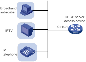
The gateway binding feature on the master device takes effect if the DHCP address pool is bound to a VSRP instance. If the address pool is applied to a VPN instance, the VPN instance must exist.
To bind the gateways to a common MAC address:
|
Step |
Command |
Remarks |
|
1. Enter system view. |
system-view |
N/A |
|
2. Create a DHCP address pool and enter its view. |
dhcp server ip-pool pool-name |
By default, no DHCP address pool exists. |
|
3. Bind the gateways to the device's MAC address. |
gateway-list ip-address&<1-64> export-route |
By default, gateways are not bound to any MAC address. |
Advertising subnets assigned to clients
As shown in Figure 23, Router A and Router B act as both the DHCP server and the BRAS device. The BRAS devices send accounting packets to the RADIUS server. To enable the BRAS devices to collect correct accounting information for each RADIUS user, configure the DHCP server to advertise subnets assigned to clients. The upstream and downstream traffic of a RADIUS user will pass through the same BRAS device.
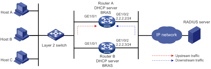
The subnet advertising on the master device takes effect if the DHCP address pool is bound to a VSRP instance. If the address pool is applied to a VPN instance, the VPN instance must exist.
To configure the subnet advertisement feature:
|
Step |
Command |
Remarks |
|
1. Enter system view. |
system-view |
N/A |
|
2. Create a DHCP address pool and enter its view. |
dhcp server ip-pool pool-name |
By default, no DHCP address pool exists. |
|
3. Advertise subnets assigned to DHCP clients. |
network network-address [ mask-length | mask mask ] export-route [ secondary ] |
By default, the subnets assigned to DHCP clients are not advertised. |
Applying a DHCP address pool to a VPN instance
If a DHCP address pool is applied to a VPN instance, the DHCP server assigns IP addresses in this address pool to clients in the VPN instance. Addresses in this address pool will not be assigned to clients on the public network.
The DHCP server can obtain the VPN instance to which a DHCP client belongs from the following information:
· The client's VPN information stored in authentication modules, such as IPoE.
· The VPN information of the DHCP server's interface that receives DHCP packets from the client.
The VPN information from authentication modules takes priority over the VPN information of the receiving interface.
To apply a DHCP address pool to a VPN instance:
|
Step |
Command |
Remarks |
|
1. Enter system view. |
system-view |
N/A |
|
2. Create a DHCP address pool and enter its view. |
dhcp server ip-pool pool-name |
By default, no DHCP address pool exists. |
|
3. Apply the address pool to a VPN instance. |
vpn-instance vpn-instance-name |
By default, no VPN instance is applied to the address pool. |
Enabling client offline detection on the DHCP server
The client offline detection feature reclaims an assigned IP address and deletes the binding entry when the ARP entry for the IP address ages out. The feature does not function if an ARP entry is manually deleted.
To enable client offline detection on the DHCP server:
|
Step |
Command |
Remarks |
|
1. Enter system view. |
system-view |
N/A |
|
2. Enter interface view. |
interface interface-type interface-number |
N/A |
|
3. Enable client offline detection. |
dhcp client-detect |
By default, client offline detection is disabled on the DHCP server. |
Enabling DHCP logging on the DHCP server
The DHCP logging feature enables the DHCP server to generate DHCP logs and send them to the information center. For information about the log destination and output rule configuration in the information center, see Network Management and Monitoring Configuration Guide.
As a best practice, disable this feature if the log generation affects the device performance or reduces the address allocation efficiency. For example, this situation might occur when a large number of clients frequently come online or go offline.
To enable DHCP logging on the DHCP server:
|
Step |
Command |
Remarks |
|
1. Enter system view. |
system-view |
N/A |
|
2. Enable DHCP logging. |
dhcp log enable |
By default, DHCP logging is disabled. |
Displaying and maintaining the DHCP server
|
|
IMPORTANT: A restart of the DHCP server or execution of the reset dhcp server ip-in-use command deletes all lease information. The DHCP server denies any DHCP request for lease extension, and the client must request an IP address again. |
Execute display commands in any view and reset commands in user view.
|
Task |
Command |
|
Display information about IP address conflicts. |
display dhcp server conflict [ ip ip-address ] [ vpn-instance vpn-instance-name ] |
|
Display information about DHCP binding auto backup. |
display dhcp server database |
|
Display information about lease-expired IP addresses. |
display dhcp server expired [ [ ip ip-address ] [ vpn-instance vpn-instance-name ] | pool pool-name ] |
|
Display information about assignable IP addresses. |
display dhcp server free-ip [ pool pool-name | vpn-instance vpn-instance-name ] |
|
Display information about assigned IP addresses. |
display dhcp server ip-in-use [ [ ip ip-address ] [ vpn-instance vpn-instance-name ] | pool pool-name ] |
|
Display DHCP server statistics. |
display dhcp server statistics [ pool pool-name | vpn-instance vpn-instance-name ] |
|
Display information about DHCP address pools. |
display dhcp server pool [ pool-name | vpn-instance vpn-instance-name ] |
|
Clear information about IP address conflicts. |
reset dhcp server conflict [ ip ip-address ] [ vpn-instance vpn-instance-name ] |
|
Clear information about lease-expired IP addresses. |
reset dhcp server expired [ [ ip ip-address ] [ vpn-instance vpn-instance-name ] | pool pool-name ] |
|
Clear information about assigned IP addresses. |
reset dhcp server ip-in-use [ [ ip ip-address ] [ vpn-instance vpn-instance-name ] | pool pool-name ] |
|
Clear DHCP server statistics. |
reset dhcp server statistics [ vpn-instance vpn-instance-name ] |
DHCP server configuration examples
DHCP networking includes the following types:
· The DHCP server and clients reside on the same subnet.
· The DHCP server and clients are not on the same subnet and communicate with each other through a DHCP relay agent.
The DHCP server configuration for the two types is identical.
Static IP address assignment configuration example
Network requirements
As shown in Figure 24, Router A (DHCP server) assigns a static IP address, a DNS server address, and a gateway address to Router B (DHCP client) and Router C (BOOTP client).
The client ID of the interface GigabitEthernet 1/0/1 on Router B is:
0030-3030-662e-6532-3030-2e30-3030-322d-4574-6865-726e-6574.
The MAC address of the interface GigabitEthernet 1/0/1 on Router C is 000f-e200-01c0.
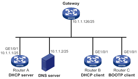
Configuration procedure
1. Specify an IP address for GigabitEthernet 1/0/1 on Router A:
<RouterA> system-view
[RouterA] interface gigabitethernet 1/0/1
[RouterA-GigabitEthernet1/0/1] ip address 10.1.1.1 25
[RouterA-GigabitEthernet1/0/1] quit
2. Configure the DHCP server:
# Enable DHCP.
[RouterA] dhcp enable
# Enable the DHCP server on GigabitEthernet 1/0/1.
[RouterA] interface gigabitethernet 1/0/1
[RouterA-GigabitEthernet1/0/1] dhcp select server
[RouterA-GigabitEthernet1/0/1] quit
# Create DHCP address pool 0.
[RouterA] dhcp server ip-pool 0
# Configure a static binding for Router B.
[RouterA-dhcp-pool-0] static-bind ip-address 10.1.1.5 25 client-identifier 0030-3030-662e-6532-3030-2e30-3030-322d-4574-6865-726e-6574
# Configure a static binding for Router C.
[RouterA-dhcp-pool-0] static-bind ip-address 10.1.1.6 25 hardware-address 000f-e200-01c0
# Specify the DNS server and gateway.
[RouterA-dhcp-pool-0] dns-list 10.1.1.2
[RouterA-dhcp-pool-0] gateway-list 10.1.1.126
[RouterA-dhcp-pool-0] quit
[RouterA]
Verifying the configuration
# Verify that Router B can obtain IP address 10.1.1.5 and all other network parameters from Router A. (Details not shown.)
# Verify that Router C can obtain IP address 10.1.1.6 and all other network parameters from Router A. (Details not shown.)
# On the DHCP server, display the IP addresses assigned to the clients.
[RouterA] display dhcp server ip-in-use
IP address Client identifier/ Lease expiration Type
Hardware address
10.1.1.5 0030-3030-662e-6532- Jan 21 14:27:27 2014 Static(C)
3030-2e30-3030-322d-
4574-6865-726e-6574
10.1.1.6 000f-e200-01c0 Unlimited Static(C)
Dynamic IP address assignment configuration example
Network requirements
As shown in Figure 25, the DHCP server (Router A) assigns IP addresses to clients on subnet 10.1.1.0/24, which is subnetted into 10.1.1.0/25 and 10.1.1.128/25.
Configure DHCP server on Router A to implement the following assignment scheme.
Table 3 Assignment scheme
|
DHCP clients |
IP address |
Lease |
Other configuration parameters |
|
Clients that connect to GigabitEthernet 1/0/1 |
IP addresses on subnet 10.1.1.0/25 |
10 days and 12 hours |
· Gateway: 10.1.1.126/25 · DNS server: 10.1.1.2/25 · Domain name: aabbcc.com · WINS server: 10.1.1.4/25 |
|
Clients that connect to GigabitEthernet 1/0/2 |
IP addresses on subnet 10.1.1.128/25 |
Five days |
· Gateway: 10.1.1.254/25 · DNS server: 10.1.1.2/25 · Domain name: aabbcc.com |
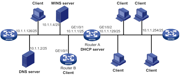
Configuration procedure
1. Specify IP addresses for interfaces. (Details not shown.)
2. Configure the DHCP server:
# Enable DHCP.
<RouterA> system-view
[RouterA] dhcp enable
# Enable the DHCP server on GigabitEthernet 1/0/1 and GigabitEthernet 1/0/2.
[RouterA] interface gigabitethernet 1/0/1
[RouterA-GigabitEthernet1/0/1] dhcp select server
[RouterA-GigabitEthernet1/0/1] quit
[RouterA] interface gigabitethernet 1/0/2
[RouterA-GigabitEthernet1/0/2] dhcp select server
[RouterA-GigabitEthernet1/0/2] quit
# Exclude addresses of the DNS server, WINS server, and gateways from dynamic allocation.
[RouterA] dhcp server forbidden-ip 10.1.1.2
[RouterA] dhcp server forbidden-ip 10.1.1.4
[RouterA] dhcp server forbidden-ip 10.1.1.126
[RouterA] dhcp server forbidden-ip 10.1.1.254
# Configure DHCP address pool 1 to assign IP addresses and other configuration parameters to clients on subnet 10.1.1.0/25.
[RouterA] dhcp server ip-pool 1
[RouterA-dhcp-pool-1] network 10.1.1.0 mask 255.255.255.128
[RouterA-dhcp-pool-1] expired day 10 hour 12
[RouterA-dhcp-pool-1] domain-name aabbcc.com
[RouterA-dhcp-pool-1] dns-list 10.1.1.2
[RouterA-dhcp-pool-1] gateway-list 10.1.1.126
[RouterA-dhcp-pool-1] nbns-list 10.1.1.4
[RouterA-dhcp-pool-1] quit
# Configure DHCP address pool 2 to assign IP addresses and other configuration parameters to clients on subnet 10.1.1.128/25.
[RouterA] dhcp server ip-pool 2
[RouterA-dhcp-pool-2] network 10.1.1.128 mask 255.255.255.128
[RouterA-dhcp-pool-2] expired day 5
[RouterA-dhcp-pool-2] domain-name aabbcc.com
[RouterA-dhcp-pool-2] dns-list 10.1.1.2
[RouterA-dhcp-pool-2] gateway-list 10.1.1.254
[RouterA-dhcp-pool-2] quit
Verifying the configuration
# Verify that clients on subnets 10.1.1.0/25 and 10.1.1.128/25 can obtain correct IP addresses and all other network parameters from Router A. (Details not shown.)
# On the DHCP server, display the IP addresses assigned to the clients.
[RouterA] display dhcp server ip-in-use
IP address Client identifier/ Lease expiration Type
Hardware address
10.1.1.3 0031-3865-392e-6262- Jan 14 22:25:03 2015 Auto(C)
3363-2e30-3230-352d-
4745-302f-30
10.1.1.5 0031-fe65-4203-7e02- Jan 14 22:25:03 2015 Auto(C)
3063-5b30-3230-4702-
620e-712f-5e
10.1.1.130 3030-3030-2e30-3030- Jan 9 10:45:11 2015 Auto(C)
662e-3030-3033-2d45-
7568-6572-1e
10.1.1.131 3030-0020-fe02-3020- Jan 9 10:45:11 2015 Auto(C)
7052-0201-2013-1e02
0201-9068-23
10.1.1.132 2020-1220-1102-3021- Jan 9 10:45:11 2015 Auto(C)
7e52-0211-2025-3402
0201-9068-9a
10.1.1.133 2021-d012-0202-4221- Jan 9 10:45:11 2015 Auto(C)
8852-0203-2022-55e0
3921-0104-31
DHCP user class configuration example
Network requirements
As shown in Figure 26, the DHCP relay agent (Router A) forwards DHCP packets between DHCP clients and the DHCP server (Router B). Enable Router A to handle Option 82 so that it can add Option 82 in DHCP requests and then convey them to the DHCP server.
Configure the address allocation scheme as follows:
|
Assign IP addresses |
To clients |
|
10.10.1.2 to 10.10.1.10 |
The DHCP request contains Option 82. |
|
10.10.1.11 to 10.10.1.26 |
The hardware address in the request is six bytes long and begins with aabb-aabb-aab. |
Router B assigns the DNS server address 10.10.1.20/24 and the gateway address 10.10.1.254/24 to clients on subnet 10.10.1.0/24.
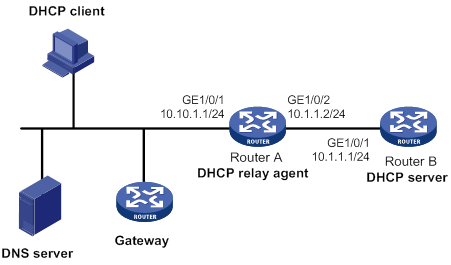
Configuration procedure
1. Specify IP addresses for the interfaces on DHCP server. (Details not shown.)
2. Configure DHCP:
# Enable DHCP and configure the DHCP server to handle Option 82.
<RouterB> system-view
[RouterB] dhcp enable
[RouterB] dhcp server relay information enable
# Enable the DHCP server on the interface GigabitEthernet1/0/1.
[RouterB] interface gigabitethernet 1/0/1
[RouterB-GigabitEthernet1/0/1] dhcp select server
[RouterB-GigabitEthernet1/0/1] quit
# Create DHCP user class tt and configure a match rule to match DHCP requests that contain Option 82.
[RouterB] dhcp class tt
[RouterB-dhcp-class-tt] if-match rule 1 option 82
[RouterB-dhcp-class-tt] quit
# Create DHCP user class ss and configure a match rule to match DHCP requests in which the hardware address is six bytes long and begins with aabb-aabb-aab.
[RouterB] dhcp class ss
[RouterB-dhcp-class-ss] if-match rule 1 hardware-address aabb-aabb-aab0 mask ffff-ffff-fff0
[RouterB-dhcp-class-ss] quit
# Create DHCP address pool aa.
[RouterB] dhcp server ip-pool aa
# Specify the subnet for dynamic allocation.
[RouterB-dhcp-pool-aa] network 10.10.1.0 mask 255.255.255.0
# Specify the address range for dynamic allocation.
[RouterB-dhcp-pool-aa] address range 10.10.1.2 10.10.1.100
# Specify the address range for the user class tt.
[RouterB-dhcp-pool-aa] class tt range 10.10.1.2 10.10.1.10
# Specify the address range for the user class ss.
[RouterB-dhcp-pool-aa] class ss range 10.10.1.11 10.10.1.26
# Specify the gateway and the DNS server.
[RouterB-dhcp-pool-aa] gateway-list 10.10.1.254
[RouterB-dhcp-pool-aa] dns-list 10.10.1.20
[RouterB-dhcp-pool-aa] quit
Verifying the configuration
# Verify that clients matching the DHCP user classes can obtain IP addresses in the specified ranges and all other configuration parameters from the DHCP server. (Details not shown.)
# On the DHCP server, display the IP addresses assigned to the clients.
[RouterB] display dhcp server ip-in-use
IP address Client identifier/ Lease expiration Type
Hardware address
10.10.1.2 0031-3865-392e-6262- Jan 14 22:25:03 2015 Auto(C)
3363-2e30-3230-352d-
4745-302f-30
10.10.1.11 aabb-aabb-aab1 Jan 14 22:25:03 2015 Auto(C)
DHCP user class whitelist configuration example
Network requirements
As shown in Figure 27, configure the DHCP user class whitelist to allow the DHCP server to assign IP addresses to clients whose hardware addresses are six bytes long and begin with aabb-aabb.
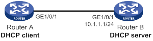
Configuration procedure
1. Specify IP addresses for the interfaces on the DHCP server. (Details not shown.)
2. Configure DHCP:
# Enable DHCP.
<RouterB> system-view
[RouterB] dhcp enable
# Enable DHCP server on interface GigabitEthernet 1/0/1.
[RouterB] interface gigabitethernet 1/0/1
[RouterB-GigabitEthernet1/0/1] dhcp select server
[RouterB-GigabitEthernet1/0/1] quit
# Create DHCP user class ss and configure a match rule to match DHCP requests in which the hardware address is six bytes long and begins with aabb-aabb.
[RouterB] dhcp class ss
[RouterB-dhcp-class-ss] if-match rule 1 hardware-address aabb-aabb-0000 mask ffff-ffff-0000
[RouterB-dhcp-class-ss] quit
# Create DHCP address pool aa.
[RouterB] dhcp server ip-pool aa
# Specify the subnet for dynamic allocation.
[RouterB-dhcp-pool-aa] network 10.1.1.0 mask 255.255.255.0
# Enable DHCP user class whitelist.
[RouterB-dhcp-pool-aa] verify class
# Add DHCP user class ss to the DHCP user class whitelist.
[RouterB-dhcp-pool-aa] valid class ss
[RouterB-dhcp-pool-aa] quit
Verifying the configuration
# Verify that clients matching the DHCP user class can obtain IP addresses on subnet 10.1.1.0/24 from the DHCP server. (Details not shown.)
# On the DHCP server, display the IP addresses assigned to the clients.
[RouterB] display dhcp server ip-in-use
IP address Client identifier/ Lease expiration Type
Hardware address
10.1.1.2 aabb-aabb-ab01 Jan 14 22:25:03 2015 Auto(C)
Primary and secondary subnets configuration example
Network requirements
As shown in Figure 28, the DHCP server (Router A) assigns IP addresses to DHCP clients in the LAN.
Configure two subnets in the address pool on the DHCP server: 10.1.1.0/24 as the primary subnet and 10.1.2.0/24 as the secondary subnet. The DHCP server selects an IP address from the secondary subnet when the primary subnet has no assignable addresses.
Router A assigns the following parameters:
· The default gateway 10.1.1.254/24 to clients on subnet 10.1.1.0/24.
· The default gateway 10.1.2.254/24 to clients on subnet 10.1.2.0/24.
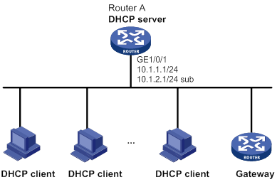
Configuration procedure
# Enable DHCP.
<RouterA> system-view
[RouterA] dhcp enable
# Configure the primary and secondary IP addresses of interface GigabitEthernet1/0/1, and enable the DHCP server on GigabitEthernet 1/0/1.
[RouterA] interface gigabitethernet 1/0/1
[RouterA-GigabitEthernet1/0/1] ip address 10.1.1.1 24
[RouterA-GigabitEthernet1/0/1] ip address 10.1.2.1 24 sub
[RouterA-GigabitEthernet1/0/1] dhcp select server
[RouterA-GigabitEthernet1/0/1] quit
# Create DHCP address pool aa.
[RouterA] dhcp server ip-pool aa
# Specify the primary subnet and the gateway for dynamic allocation.
[RouterA-dhcp-pool-aa] network 10.1.1.0 mask 255.255.255.0
[RouterA-dhcp-pool-aa] gateway-list 10.1.1.254
# Specify the secondary subnet and the gateway for dynamic allocation.
[RouterA-dhcp-pool-aa] network 10.1.2.0 mask 255.255.255.0 secondary
[RouterA-dhcp-pool-aa-secondary] gateway-list 10.1.2.254
[RouterA-dhcp-pool-aa-secondary] quit
[RouterA-dhcp-pool-aa] quit
Verifying the configuration
# Verify that the DHCP server assigns clients IP addresses and gateway address from the secondary subnet when no assignable address is available from the primary subnet. (Details not shown.)
# On the DHCP server, display IP addresses assigned to the clients. The following is part of the command output.
[RouterA] display dhcp server ip-in-use
IP address Client identifier/ Lease expiration Type
Hardware address
10.1.1.2 0031-3865-392e-6262- Jan 14 22:25:03 2015 Auto(C)
3363-2e30-3230-352d-
4745-302f-30
10.1.2.2 3030-3030-2e30-3030- Jan 14 22:25:03 2015 Auto(C)
662e-3030-3033-2d45-
7568-6572-1e
DHCP option customization configuration example
Network requirements
As shown in Figure 29, DHCP clients obtain IP addresses and PXE server addresses from the DHCP server (Router A). The subnet for address allocation is 10.1.1.0/24.
Configure the address allocation scheme as follows:
|
Assign PXE addresses |
To clients |
|
2.3.4.5 and 3.3.3.3 |
The hardware address in the request is six bytes long and begins with aabb-aabb. |
|
1.2.3.4 and 2.2.2.2. |
Other clients. |
The DHCP server assigns PXE server addresses to DHCP clients through Option 43, a custom option. The formats of Option 43 and PXE server address sub-option are shown in Figure 19 and Figure 21. For example, the value of Option 43 configured in the DHCP address pool is 80 0B 00 00 02 01 02 03 04 02 02 02 02.
· The number 80 is the value of the sub-option type.
· The number 0B is the value of the sub-option length.
· The numbers 00 00 are the value of the PXE server type.
· The number 02 indicates the number of servers.
· The numbers 01 02 03 04 02 02 02 02 indicate that the PXE server addresses are 1.2.3.4 and 2.2.2.2.
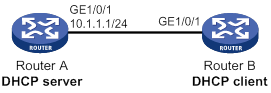
Configuration procedure
1. Specify an IP address for interface GigabitEthernet 1/0/1. (Details not shown.)
2. Configure the DHCP server:
# Enable DHCP.
<RouterA> system-view
[RouterA] dhcp enable
# Create DHCP user class ss and configure a match rule to match DHCP requests in which the hardware address is six bytes long and begins with aabb-aabb.
[RouterA] dhcp class ss
[RouterA-dhcp-class-ss] if-match rule 1 hardware-address aabb-aabb-0000 mask ffff-ffff-0000
[RouterA-dhcp-class-ss] quit
# Create DHCP option group 1 and customize Option 43.
[RouterA] dhcp option-group 1
[RouterA-dhcp-option-group-1] option 43 hex 800B0000020203040503030303
# Enable the DHCP server on GigabitEthernet 1/0/1.
[RouterA] interface gigabitethernet 1/0/1
[RouterA-GigabitEthernet1/0/1] dhcp select server
[RouterA-GigabitEthernet1/0/1] quit
# Create DHCP address pool 0.
[RouterA] dhcp server ip-pool 0
# Specify the subnet for dynamic address allocation.
[RouterA-dhcp-pool-0] network 10.1.1.0 mask 255.255.255.0
# Customize Option 43.
[RouterA-dhcp-pool-0] option 43 hex 800B0000020102030402020202
# Associate DHCP user class ss with option group 1.
[RouterA-dhcp-pool-0] class ss option-group 1
[RouterA-dhcp-pool-0] quit
Verifying the configuration
# Verify that Router B can obtain an IP address on subnet 10.1.1.0/24 and the corresponding PXE server addresses from Router A. (Details not shown.)
# On the DHCP server, display the IP addresses assigned to the clients.
[RouterA] display dhcp server ip-in-use
IP address Client identifier/ Lease expiration Type
Hardware address
10.1.1.2 aabb-aabb-ab01 Jan 14 22:25:03 2015 Auto(C)
Troubleshooting DHCP server configuration
Failure to obtain a non-conflicting IP address
Symptom
A client's IP address obtained from the DHCP server conflicts with another IP address.
Solution
Another host on the subnet might have the same IP address.
To resolve the problem:
1. Disable the client's network adapter or disconnect the client's network cable. Ping the IP address of the client from another host to check whether there is a host using the same IP address.
2. If a ping response is received, the IP address has been manually configured on a host. Execute the dhcp server forbidden-ip command on the DHCP server to exclude the IP address from dynamic allocation.
3. Enable the network adapter or connect the network cable, release the IP address, and obtain another one on the client. For example, to release the IP address and obtain another one on a Windows XP DHCP client:
a. In Windows environment, execute the cmd command to enter the DOS environment.
b. Enter ipconfig /release to relinquish the IP address.
c. Enter ipconfig /renew to obtain another IP address.
Configuring the DHCP relay agent
Overview
The DHCP relay agent enables clients to get IP addresses from a DHCP server on another subnet. This feature avoids deploying a DHCP server for each subnet to centralize management and reduce investment. Figure 30 shows a typical application of the DHCP relay agent.
Figure 30 DHCP relay agent application
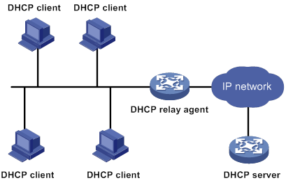
An MCE device acting as the DHCP relay agent can forward DHCP packets between a DHCP server and clients on either a public network or a private network. For more information about MCE, see MPLS Configuration Guide.
Operation
The DHCP server and client interact with each other in the same way regardless of whether the relay agent exists. For the interaction details, see "IP address allocation process." The following only describes steps related to the DHCP relay agent:
1. After receiving a DHCP-DISCOVER or DHCP-REQUEST broadcast message from a DHCP client, the DHCP relay agent processes the message as follows:
a. Fills the giaddr field of the message with its IP address.
b. Unicasts the message to the designated DHCP server.
2. Based on the giaddr field, the DHCP server returns an IP address and other configuration parameters in a response.
3. The relay agent conveys the response to the client.
Figure 31 DHCP relay agent operation
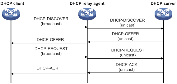
DHCP relay agent support for Option 82
Option 82 records the location information about the DHCP client. It enables the administrator to perform the following tasks:
· Locate the DHCP client for security and accounting purposes.
· Assign IP addresses in a specific range to clients.
For more information about Option 82, see "Relay agent option (Option 82)."
If the DHCP relay agent supports Option 82, it handles DHCP requests by following the strategies described in Table 4.
If a response returned by the DHCP server contains Option 82, the DHCP relay agent removes the Option 82 before forwarding the response to the client.
Table 4 Handling strategies of the DHCP relay agent
|
If a DHCP request has… |
Handling strategy |
The DHCP relay agent… |
|
Option 82 |
Drop |
Drops the message. |
|
Keep |
Forwards the message without changing Option 82. |
|
|
Replace |
Forwards the message after replacing the original Option 82 with the Option 82 padded according to the configured padding format, padding content, and code type. |
|
|
No Option 82 |
N/A |
Forwards the message after adding Option 82 padded according to the configured padding format, padding content, and code type. |
DHCP relay agent configuration task list
|
Tasks at a glance |
|
(Required.) Enabling DHCP |
|
(Required.) Enabling the DHCP relay agent on an interface |
|
(Required.) Specifying DHCP servers on a relay agent |
|
(Optional.) Specifying the source address and gateway address in DHCP requests |
|
(Optional.) Configuring the DHCP relay agent security features |
|
(Optional.) Configuring the DHCP relay agent to release an IP address |
|
(Optional.) Configuring Option 82 |
|
(Optional.) Setting the DSCP value for DHCP packets sent by the DHCP relay agent |
|
(Optional.) Enabling DHCP server proxy on a DHCP relay agent |
|
(Optional.) Configuring a DHCP relay address pool |
|
(Optional.) Specifying a gateway address for DHCP clients |
|
(Optional.) Enabling client offline detection on the DHCP relay agent |
|
(Optional.) Configuring the DHCP smart relay feature |
|
(Optional.) Configuring the DHCP relay agent to forward DHCP replies based on Option 82 |
Enabling DHCP
You must enable DHCP to validate other DHCP relay agent settings.
To enable DHCP:
|
Step |
Command |
Remarks |
|
1. Enter system view. |
system-view |
N/A |
|
2. Enable DHCP. |
dhcp enable |
By default, DHCP is disabled. |
Enabling the DHCP relay agent on an interface
With the DHCP relay agent enabled, an interface forwards incoming DHCP requests to a DHCP server.
An IP address pool that contains the IP address of the DHCP relay interface must be configured on the DHCP server. Otherwise, the DHCP clients connected to the relay agent cannot obtain correct IP addresses.
To enable the DHCP relay agent on an interface:
|
Step |
Command |
Remarks |
|
1. Enter system view. |
system-view |
N/A |
|
2. Enter interface view. |
interface interface-type interface-number |
N/A |
|
3. Enable the DHCP relay agent. |
dhcp select relay |
By default, when DHCP is enabled, an interface operates in the DHCP server mode. |
Specifying DHCP servers on a relay agent
To improve availability, you can specify several DHCP servers on the DHCP relay agent. When the interface receives request messages from clients, the relay agent forwards them to all DHCP servers.
Follow these guidelines when you specify a DHCP server address on a relay agent:
· The IP address of any specified DHCP server must not reside on the same subnet as the IP address of the relay interface. Otherwise, the clients might fail to obtain IP addresses.
· You can specify a maximum of eight DHCP servers.
To specify a DHCP server address on a relay agent:
|
Command |
Remarks |
|
|
1. Enter system view. |
system-view |
N/A |
|
2. Enter interface view. |
interface interface-type interface-number |
N/A |
|
3. Specify a DHCP server address on the relay agent. |
dhcp relay server-address ip-address |
By default, no DHCP server address is specified on the relay agent. |
Specifying the source address and gateway address in DHCP requests
Perform this task to configure the relay agent to pad the source address and gateway address in DHCP requests with the public IP address of the loopback interface. This configuration is required for successful packet forwarding when the DHCP server is in the public network and the DHCP clients are in a private network.
To use this feature, you must configure the sub-option 72 in Option 82 to carry the index of the interface that processes the DHCP request. When receiving a DHCP response, the relay agent forwards the response according to the interface index in sub-option 72.
To specify the source address and gateway address in DHCP requests:
|
Step |
Command |
Remarks |
|
1. Enter system view. |
system-view |
N/A |
|
2. Enter interface view. |
interface interface-type interface-number |
N/A |
|
3. Specify an IP address as the source address and gateway address in DHCP requests. |
dhcp relay source-address ip-address |
By default, the IP address of the interface is used as the source address and gateway address in DHCP requests. |
Configuring the DHCP relay agent security features
Enabling the DHCP relay agent to record relay entries
Perform this task to enable the DHCP relay agent to automatically record clients' IP-to-MAC bindings (relay entries) after they obtain IP addresses through DHCP.
Some security features use the relay entries to check incoming packets and block packets that do not match any entry. In this way, illegal hosts are not able to access external networks through the relay agent. Examples of the security features are ARP address check, authorized ARP, and IP source guard.
To enable the DHCP relay agent to record relay entries:
|
Step |
Command |
Remarks |
|
1. Enter system view. |
system-view |
N/A |
|
2. Enable the relay agent to record relay entries. |
dhcp relay client-information record |
By default, the relay agent does not record relay entries. |
|
|
NOTE: The DHCP relay agent does not record IP-to-MAC bindings for DHCP clients running on synchronous/asynchronous serial interfaces. |
Enabling periodic refresh of dynamic relay entries
A DHCP client unicasts a DHCP-RELEASE message to the DHCP server to release its IP address. The DHCP relay agent conveys the message to the DHCP server and does not remove the IP-to-MAC entry of the client.
With this feature, the DHCP relay agent uses the following information to periodically send a DHCP-REQUEST message to the DHCP server:
· The IP address of a relay entry.
· The MAC address of the DHCP relay interface.
The relay agent maintains the relay entries depending on what it receives from the DHCP server:
· If the server returns a DHCP-ACK message or does not return any message within an interval, the DHCP relay agent removes the relay entry. In addition, upon receiving the DHCP-ACK message, the relay agent sends a DHCP-RELEASE message to release the IP address.
· If the server returns a DHCP-NAK message, the relay agent keeps the relay entry.
To enable periodic refresh of dynamic relay entries:
|
Step |
Command |
Remarks |
|
1. Enter system view. |
system-view |
N/A |
|
2. Enable periodic refresh of dynamic relay entries. |
dhcp relay client-information refresh enable |
By default, periodic refresh of dynamic relay entries is enabled. |
|
3. Set the refresh interval. |
dhcp relay client-information refresh [ auto | interval interval ] |
By default, the refresh interval is auto, which is calculated based on the number of total relay entries. |
Enabling DHCP starvation attack protection
A DHCP starvation attack occurs when an attacker constantly sends forged DHCP requests using different MAC addresses in the chaddr field to a DHCP server. This exhausts the IP address resources of the DHCP server so legitimate DHCP clients cannot obtain IP addresses. The DHCP server might also fail to work because of exhaustion of system resources. The following methods are available to relieve or prevent such attacks.
· To relieve a DHCP starvation attack that uses DHCP packets encapsulated with different source MAC addresses, you can use one of the following methods:
? Limit the number of ARP entries that a Layer 3 interface can learn.
? Limit the number of MAC addresses that a Layer 2 port can learn.
? Configure an interface that has learned the maximum MAC addresses to discard packets whose source MAC addresses are not in the MAC address table.
· To prevent a DHCP starvation attack that uses DHCP requests encapsulated with the same source MAC address, you can enable MAC address check on the DHCP relay agent. After you enable this feature, the DHCP relay agent processes a DHCP request as follows:
? Directly forwards the DHCP request if the giaddr field is not zero.
? Compares the chaddr field in the DHCP request with the source MAC address in the frame header if the giaddr field is zero. If they are the same, the DHCP relay agent forwards the request to the DHCP server. If they are not the same, the DHCP relay agent discards the request.
MAC address check takes effect only when the dhcp select relay command has already been configured on the interface.
A DHCP relay agent changes the source MAC address of DHCP packets before sending them. You can only enable MAC address check only on the DHCP relay agent directly connected to the DHCP clients.
A MAC address check entry has an aging time. When the aging time expires, both of the following occur:
· The entry ages out.
· The DHCP relay agent rechecks the validity of DHCP requests sent from the MAC address in the entry.
To enable MAC address check:
|
Step |
Command |
Remarks |
|
1. Enter system view. |
system-view |
N/A |
|
2. Set the aging time for MAC address check entries. |
dhcp relay check mac-address aging-time time |
The default aging time is 30 seconds. This command takes effect only after you execute the dhcp relay check mac-address command. |
|
3. Enter the interface view. |
interface interface-type interface-number |
N/A |
|
4. Enable MAC address check. |
dhcp relay check mac-address |
By default, MAC address check is disabled. |
Configuring the DHCP relay agent to release an IP address
Configure the relay agent to release the IP address for a relay entry. The relay agent sends a DHCP-RELEASE message to the server and meanwhile deletes the relay entry. Upon receiving the DHCP-RELEASE message, the DHCP server releases the IP address.
To configure the DHCP relay agent to release an IP address:
|
Step |
Command |
Remarks |
|
1. Enter system view. |
system-view |
N/A |
|
2. Configure the DHCP relay agent to release an IP address. |
dhcp relay release ip ip-address [ vpn-instance vpn-instance-name ] |
This command can release only the IP addresses in the recorded relay entries. |
Configuring Option 82
Follow these guidelines when you configure Option 82:
· To support Option 82, you must perform related configuration on both the DHCP server and relay agent. For DHCP server Option 82 configuration, see "Enabling handling of Option 82."
· If the handling strategy is replace, configure a padding mode and padding format for Option 82. If the handling strategy is keep or drop, you do not need to configure any padding mode or padding format for Option 82. The settings do not take effect even if you configure them.
· The device name (sysname) must not include spaces if it is configured as the padding content for sub-option 1. Otherwise, the DHCP relay agent will fail to add or replace Option 82.
|
Step |
Command |
Remarks |
|
1. Enter system view. |
system-view |
N/A |
|
2. Enter interface view. |
interface interface-type interface-number |
N/A |
|
3. Enable the relay agent to handle Option 82. |
dhcp relay information enable |
By default, handling of Option 82 is disabled. |
|
4. (Optional.) Configure the strategy for handling DHCP requests that contain Option 82. |
dhcp relay information strategy { drop | keep | replace } |
By default, the handling strategy is replace. |
|
5. (Optional.) Configure the padding mode and padding format for the Circuit ID sub-option. |
dhcp relay information circuit-id { bas [ sub-interface-vlan ] | string circuit-id | { normal | verbose [ node-identifier { mac | sysname | user-defined node-identifier } ] [ interface ] } [ sub-interface-vlan ] [ format { ascii | hex } ] } |
By default, the padding mode for Circuit ID sub-option is normal, and the padding format is hex. |
|
6. (Optional.) Configure the padding mode and padding format for the Remote ID sub-option. |
dhcp relay information remote-id { normal [ format { ascii | hex } ] | string remote-id | sysname } |
By default, the padding mode for the Remote ID sub-option is normal, and the padding format is hex. |
Setting the DSCP value for DHCP packets sent by the DHCP relay agent
The DSCP value of a packet specifies the priority level of the packet and affects the transmission priority of the packet.
To set the DSCP value for DHCP packets sent by the DHCP relay agent:
|
Step |
Command |
Remarks |
|
1. Enter system view. |
system-view |
N/A |
|
2. Set the DSCP value for DHCP packets sent by the DHCP relay agent. |
dhcp dscp dscp-value |
By default, the DSCP value in DHCP packets sent by the DHCP relay agent is 56. |
Enabling DHCP server proxy on a DHCP relay agent
The DHCP server proxy feature isolates DHCP servers from DHCP clients and protects DHCP servers against attacks.
Upon receiving a response from the server, the DHCP server proxy modifies the server's IP address as the relay interface's IP address before sending out the response. The DHCP client takes the DHCP relay agent as the DHCP server.
To configure DHCP server proxy on a DHCP relay agent:
|
Step |
Command |
Remarks |
|
1. Enter system view. |
system-view |
N/A |
|
2. Enter interface view. |
interface interface-type interface-number |
N/A |
|
3. Enable DHCP relay agent and DHCP server proxy on the interface. |
dhcp select relay proxy |
By default, the interface operates in DHCP server mode. |
Configuring a DHCP relay address pool
This feature allows DHCP clients of the same type to obtain IP addresses and other configuration parameters from the DHCP servers specified in the matching relay address pool.
It applies to scenarios where the DHCP relay agent connects to clients of the same access type but classified into different types by their locations. In this case, the relay interface typically has no IP address configured. You can use the gateway-list command to specify the gateway address for clients matching the same relay address pool and bind the gateway address to the device's MAC address. Example network is the IPoE network.
Upon receiving a DHCP DISCOVER or REQUEST from a client that matches a relay address pool, the relay agent processes the packet as follows:
· Fills the giaddr field of the packet with the specified gateway address.
· Forwards the packet to all DHCP servers in the matching relay address pool.
The DHCP servers select an address pool according to the gateway address.
If PPPoE users are in the network, follow these restrictions and guidelines when you configure the relay address pool:
· Enable the DHCP relay agent to record DHCP relay entries by using the dhcp relay client-information record command. When a PPPoE user goes offline, the DHCP relay agent can find a matching relay entry and send a DHCP-RELEASE message to the DHCP server. This mechanism ensures that the DHCP server is aware of the releasing of the IP address in a timely manner.
· The remote-server command also configures the device as a DHCP relay agent. You do not need to enable the DHCP relay agent by using the dhcp select relay command.
To configure a DHCP relay address pool:
|
Step |
Command |
Remarks |
|
1. Enter system view. |
system-view |
N/A |
|
2. Create a DHCP relay address pool and enter its view. |
dhcp server ip-pool pool-name |
By default, no DHCP relay address pool exists. This command is the same for creating DHCP address pools on a DHCP server. However, the relay address pool names are not necessarily the same as the server address pool names. |
|
3. Specify gateway addresses for the clients matching the relay address pool. |
gateway-list ip-address&<1-64> [ export-route ] |
By default, no gateway address is specified. |
|
4. Specify DHCP servers for the relay address pool. |
remote-server ip-address&<1-8> |
By default, no DHCP server is specified for the relay address pool. You can specify a maximum of eight DHCP servers for one relay address pool for high availability. The relay agent forwards DHCP DISCOVER and REQUEST packets to all DHCP servers in the relay address pool. |
Specifying a gateway address for DHCP clients
By default, the DHCP relay agent fills the giaddr field of DHCP DISCOVER and REQUEST packets with the primary IP address of the relay interface. You can specify a gateway address on the relay agent for DHCP clients. The DHCP relay agent uses the specified gateway address to fill the giaddr field of DHCP DISCOVER and REQUEST packets.
To specify a gateway address for DHCP clients:
|
Step |
Command |
Remarks |
|
1. Enter system view. |
system-view |
N/A |
|
2. Enter interface view. |
interface interface-type interface-number |
N/A |
|
3. Specify a gateway address for DHCP clients. |
dhcp relay gateway ip-address |
By default, the DHCP relay agent uses the primary IP address of the relay interface as the clients' gateway address. |
Enabling client offline detection on the DHCP relay agent
When an ARP entry ages out, the client offline detection feature deletes the relay entry for the IP address and sends a RELEASE message to the DHCP server. The feature does not function if an ARP entry is manually deleted.
To enable client offline detection on the DHCP relay agent:
|
Step |
Command |
Remarks |
|
1. Enter system view. |
system-view |
N/A |
|
2. Enable the relay agent to record relay entries. |
dhcp relay client-information record |
By default, the relay agent does not record relay entries. Without relay entries, client offline detection cannot function correctly. |
|
3. Enter interface view. |
interface interface-type interface-number |
N/A |
|
4. Enable the DHCP relay agent. |
dhcp select relay |
By default, when DHCP is enabled, an interface operates in the DHCP server mode. |
|
5. Enable client offline detection. |
dhcp client-detect |
By default, client offline detection is disabled on the DHCP relay agent. |
Configuring the DHCP smart relay feature
The DHCP smart relay feature allows the DHCP relay agent to pad secondary IP addresses when the DHCP server does not send back the DHCP-OFFER message.
The relay agent initially pads its primary IP address to the giaddr field before forwarding a request to the DHCP server. If no DHCP-OFFER is received, the relay agent allows the client to send a maximum of two requests to the DHCP server by using the primary IP address. If no DHCP-OFFER is returned after two retries, the relay agent switches to a secondary IP address. If the DHCP server still does not respond, the next secondary IP address is used. After the secondary IP addresses are all tried and the DHCP server does not respond, the relay agent repeats the process by starting from the primary IP address.
Without this feature, the relay agent only pads the primary IP address to the giaddr field of all requests.
On a relay agent where relay address pools and gateway addresses are configured, the smart relay feature starts the process from the first gateway address. For more information about the relay address pool configuration, see "Configuring a DHCP relay address pool."
To configure the DHCP smart relay feature for a common network:
|
Step |
Command |
Remarks |
|
1. Enter system view. |
system-view |
N/A |
|
2. Enter interface view. |
interface interface-type interface-number |
N/A |
|
3. Enable the DHCP relay agent. |
dhcp select relay |
By default, an interface operates in the DHCP server mode when DHCP is enabled. |
|
4. Assign primary and secondary IP addresses to the DHCP relay agent. |
ip address ip-address { mask-length | mask } [ sub ] |
By default, the DHCP relay agent does not have any IP addresses. |
|
5. Return to system view. |
quit |
N/A |
|
6. Enable the DHCP smart relay feature. |
dhcp smart-relay enable |
By default, the DHCP smart relay feature is disabled. |
To configure the DHCP smart relay feature for a network with relay address pools:
|
Step |
Command |
Remarks |
|
|
1. Enter system view. |
system-view |
N/A |
|
|
2. Enter interface view. |
interface interface-type interface-number |
N/A |
|
|
3. Enable the DHCP relay agent. |
dhcp select relay |
By default, an interface operates in the DHCP server mode when DHCP is enabled. |
|
|
4. Return to system view. |
quit |
N/A |
|
|
5. Create a DHCP relay address pool and enter its view. |
dhcp server ip-pool pool-name |
By default, no DHCP relay address pool exists. This command is the same for creating DHCP address pools on a DHCP server. However, the relay address pool names are not necessarily the same as the server address pool names. |
|
|
6. Specify gateway addresses for the clients matching the relay address pool. |
gateway-list ip-address&<1-64> [ export-route ] |
By default, the relay address pool does not have any gateway addresses. |
|
|
7. Specify DHCP servers for the relay address pool. |
remote-server ip-address&<1-8> |
By default, the relay address pool does not have any DHCP server IP addresses. You can specify a maximum of eight DHCP servers for one relay address pool for high availability. The relay agent forwards DHCP-DISCOVER and DHCP-REQUEST packets to all DHCP servers in the relay address pool. |
|
|
8. Return to system view. |
quit |
N/A |
|
|
9. Enable the DHCP smart relay feature. |
dhcp smart-relay enable |
By default, the DHCP smart relay feature is disabled. |
|
Specifying the source IP address for relayed DHCP requests
This task is required if multiple relay interfaces share the same IP address or if a relay interface does not have routes to DHCP servers. You can perform this task to specify an IP address or the IP address of another interface on the DHCP relay agent as the source IP address for relayed DHCP requests. If an authorized address pool exists on the DHCP relay agent, the dhcp relay source-address ip-address command changes not only the source IP address but also the giaddr field. For more information about configuring authorization IP address pools for users, see AAA configuration in Security Configuration Guide.
To specify the source IP address for relayed DHCP requests:
|
Step |
Command |
Remarks |
|
1. Enter system view. |
system-view |
N/A |
|
2. Enter interface view. |
interface interface-type interface-number |
N/A |
|
3. Specify the source IP address for relayed DHCP requests. |
dhcp relay source-address { ip-address | gateway | relay-interface } |
By default, the DHCP relay agent uses the IP address of the interface that connects to the DHCP server as the source IP address for relayed DHCP requests. You can specify only one source IP address for relayed DHCP requests on an interface. |
Configuring the DHCP relay agent to forward DHCP replies based on Option 82
Configure this feature if the DHCP relay agent is required to forward DHCP replies to DHCP clients based on Option 82.
For example, an IPRAN network has a primary gateway and a secondary gateway. An L3VE interface is configured as the relay interface on each of the gateways. Multiple L2VE subinterfaces are configured to receive packets. One L2VE subinterface corresponds to one PW. Only the primary gateway receives DHCP requests, but both the primary and secondary gateways might receive DHCP replies. The primary gateway can forward DHCP replies based on locally recorded user information, but the secondary gateway cannot. The secondary gateway can only forward DHCP replies to all PWs.
To enable the secondary gateway to forward a DHCP reply to only the intended PW, perform the following tasks:
· Configure the dhcp relay information enable and dhcp relay information circuit-id (with sub-interface-vlan specified) commands on the primary gateway. Then, when the primary gateway receives a DHCP request, it adds Option 82 to the reply and record the VLAN ID of the L2VE subinterface.
· Configure the dhcp relay information enable, dhcp relay information circuit-id (with sub-interface-vlan specified), and dhcp relay forward reply by-option82 commands on the secondary gateway. Then, when the secondary gateway receives a DHCP reply, it resolves Option 82, records the VLAN ID of the L2VE subinterface, and forwards the reply to the PW.
To configure the DHCP relay agent to forward DHCP replies based on Option 82:
|
Step |
Command |
Remarks |
|
1. Enter system view. |
system-view |
N/A |
|
2. Enter interface view. |
interface interface-type interface-number |
N/A |
|
3. Enable the relay agent to handle Option 82. |
dhcp relay information enable |
By default, handling of Option 82 is disabled. |
|
4. Configure the padding mode and padding format for the Circuit ID sub-option. |
dhcp relay information circuit-id { bas [ sub-interface-vlan ] | string circuit-id | { normal | verbose [ node-identifier { mac | sysname | user-defined node-identifier } ] [ interface ] } [ sub-interface-vlan ] [ format { ascii | hex } ] } |
By default, the padding mode for the Circuit ID sub-option is normal, and the padding format is hex. The device name (set by using the sysname command) must not include spaces if it is configured as the padding content for sub-option 1. Otherwise, the DHCP relay agent will fail to add or replace Option 82. You must set the padding mode to bas, normal, or verbose, and specify the sub-interface-vlan keyword for this command. |
|
5. Configure the DHCP relay agent to forward DHCP replies based on Option 82. |
dhcp relay forward reply by-option82 |
By default, the DHCP relay agent does not forward DHCP replies based on Option 82. |
Displaying and maintaining the DHCP relay agent
Execute display commands in any view and reset commands in user view.
|
Task |
Command |
|
Display information about DHCP servers on an interface. |
display dhcp relay server-address [ interface interface-type interface-number ] |
|
Display Option 82 configuration information on the DHCP relay agent. |
display dhcp relay information [ interface interface-type interface-number ] |
|
Display relay entries on the DHCP relay agent. |
display dhcp relay client-information [ interface interface-type interface-number | ip ip-address [ vpn-instance vpn-instance-name ] ] |
|
Display packet statistics on the DHCP relay agent. |
display dhcp relay statistics [ interface interface-type interface-number ] |
|
Display MAC address check entries on the DHCP relay agent. |
display dhcp relay check mac-address |
|
Clear relay entries on the DHCP relay agent. |
reset dhcp relay client-information [ interface interface-type interface-number | ip ip-address [ vpn-instance vpn-instance-name ] ] |
|
Clear packet statistics on the DHCP relay agent. |
reset dhcp relay statistics [ interface interface-type interface-number ] |
DHCP relay agent configuration examples
DHCP relay agent configuration example
Network requirements
As shown in Figure 32, configure the DHCP relay agent on Router A. The DHCP relay agent enables DHCP clients to obtain IP addresses and other configuration parameters from the DHCP server on another subnet.
Because the DHCP relay agent and server are on different subnets, you need to configure static or dynamic routing to make them reachable to each other.
DHCP server configuration is also required to guarantee the client-server communication through the DHCP relay agent. For DHCP server configuration information, see "DHCP server configuration examples."
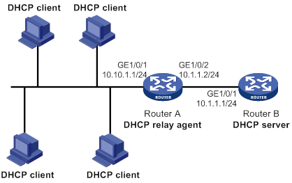
Configuration procedure
# Specify IP addresses for the interfaces. (Details not shown.)
# Enable DHCP.
<RouterA> system-view
[RouterA] dhcp enable
# Enable the DHCP relay agent on GigabitEthernet 1/0/1.
[RouterA] interface gigabitethernet 1/0/1
[RouterA-GigabitEthernet1/0/1] dhcp select relay
# Specify the IP address of the DHCP server on the relay agent.
[RouterA-GigabitEthernet1/0/1] dhcp relay server-address 10.1.1.1
Verifying the configuration
# Verify that DHCP clients can obtain IP addresses and all other network parameters from the DHCP server through the DHCP relay agent. (Details not shown.)
# Display the statistics of DHCP packets forwarded by the DHCP relay agent.
[RouterA] display dhcp relay statistics
# Display relay entries if you have enabled relay entry recording on the DHCP relay agent.
[RouterA] display dhcp relay client-information
Option 82 configuration example
Network requirements
As shown in Figure 32, the DHCP relay agent (Router A) replaces Option 82 in DHCP requests before forwarding them to the DHCP server (Router B).
· The Circuit ID sub-option is company001.
· The Remote ID sub-option is device001.
To use Option 82, you must also enable the DHCP server to handle Option 82.
Configuration procedure
# Specify IP addresses for the interfaces. (Details not shown.)
# Enable DHCP.
<RouterA> system-view
[RouterA] dhcp enable
# Enable the DHCP relay agent on GigabitEthernet 1/0/1.
[RouterA] interface gigabitethernet 1/0/1
[RouterA-GigabitEthernet1/0/1] dhcp select relay
# Specify the IP address of the DHCP server on the relay agent.
[RouterA-GigabitEthernet1/0/1] dhcp relay server-address 10.1.1.1
# Enable the DHCP relay agent to handle Option 82, and perform Option 82 related configuration.
[RouterA-GigabitEthernet1/0/1] dhcp relay information enable
[RouterA-GigabitEthernet1/0/1] dhcp relay information strategy replace
[RouterA-GigabitEthernet1/0/1] dhcp relay information circuit-id string company001
[RouterA-GigabitEthernet1/0/1] dhcp relay information remote-id string device001
Troubleshooting DHCP relay agent configuration
Failure of DHCP clients to obtain configuration parameters through the DHCP relay agent
Symptom
DHCP clients cannot obtain configuration parameters through the DHCP relay agent.
Solution
Some problems might occur with the DHCP relay agent or server configuration.
To locate the problem, enable debugging and execute the display command on the DHCP relay agent to view the debugging information and interface state information.
Check that:
· DHCP is enabled on the DHCP server and relay agent.
· The DHCP server has an address pool on the same subnet as the DHCP clients.
· The DHCP server and DHCP relay agent can reach each other.
· The DHCP server address specified on the DHCP relay interface connected to the DHCP clients is correct.
Configuring the DHCP client
With DHCP client enabled, an interface uses DHCP to obtain configuration parameters from the DHCP server, for example, an IP address.
The DHCP client configuration is supported only on Layer 3 Ethernet interfaces (or subinterfaces), VLAN interfaces, and Layer 3 aggregate interfaces.
Enabling the DHCP client on an interface
Follow these guidelines when you enable the DHCP client on an interface:
· On some device models, if the number of IP address request failures reaches the system-defined amount, the DHCP client-enabled interface uses a default IP address.
· An interface can be configured to acquire an IP address in multiple ways. The new configuration overwrites the old.
· Secondary IP addresses cannot be configured on an interface that is enabled with the DHCP client.
· If the interface obtains an IP address on the same segment as another interface on the device, the interface does not use the assigned address. Instead, it requests a new IP address from the DHCP server.
To enable the DHCP client on an interface:
|
Step |
Command |
Remarks |
|
1. Enter system view. |
system-view |
N/A |
|
2. Enter interface view. |
interface interface-type interface-number |
N/A |
|
3. Configure an interface to use DHCP for IP address acquisition. |
ip address dhcp-alloc |
By default, an interface does not use DHCP for IP address acquisition. |
Configuring a DHCP client ID for an interface
A DHCP client ID is added to the DHCP option 61. A DHCP server can specify IP addresses for clients based on the DHCP client ID.
Make sure the IDs for different DHCP clients are unique.
To configure a DHCP client ID for an interface:
|
Step |
Command |
Remarks |
|
1. Enter system view. |
system-view |
N/A |
|
2. Enter interface view. |
interface interface-type interface-number |
N/A |
|
3. Configure a DHCP client ID for the interface. |
dhcp client identifier { ascii ascii-string | hex hex-string | mac interface-type interface-number } |
By default, an interface generates the DHCP client ID based on its MAC address. If the interface has no MAC address, it uses the MAC address of the first Ethernet interface to generate its client ID. |
|
4. Verify the client ID configuration. |
display dhcp client [ verbose ] [ interface interface-type interface-number ] |
DHCP client ID includes ID type and type value. Each ID type has a fixed type value. You can check the fields for the client ID to verify which type of client ID is used: · If an ASCII string is used as the client ID, the type value is 00. · If a hexadecimal string is used as the client ID, the type value is the first two characters in the string. · If the MAC address of an interface is used as the client ID, the type value is 01. |
Enabling duplicated address detection
DHCP client detects IP address conflict through ARP packets. An attacker can act as the IP address owner to send an ARP reply. The spoofing attack makes the client unable to use the IP address assigned by the server. As a best practice, disable duplicate address detection when ARP attacks exist on the network.
To enable duplicated address detection:
|
Step |
Command |
Remarks |
|
1. Enter system view. |
system-view |
N/A |
|
2. Enable duplicate address detection. |
dhcp client dad enable |
By default, the duplicate address detection feature is enabled on an interface. |
Setting the DSCP value for DHCP packets sent by the DHCP client
The DSCP value of a packet specifies the priority level of the packet and affects the transmission priority of the packet.
To set the DSCP value for DHCP packets sent by the DHCP client:
|
Step |
Command |
Remarks |
|
1. Enter system view. |
system-view |
N/A |
|
2. Set the DSCP value for DHCP packets sent by the DHCP client. |
dhcp client dscp dscp-value |
By default, the DSCP value in DHCP packets sent by the DHCP client is 56. |
Displaying and maintaining the DHCP client
Execute display command in any view.
|
Task |
Command |
|
Display DHCP client information. |
display dhcp client [ verbose ] [ interface interface-type interface-number ] |
DHCP client configuration example
Network requirements
As shown in Figure 34, Router B contacts the DHCP server through GigabitEthernet 1/0/1 to obtain an IP address, a DNS server address, and static route information. The DHCP client's IP address resides on subnet 10.1.1.0/24. The DNS server address is 20.1.1.1. The next hop of the static route to subnet 20.1.1.0/24 is 10.1.1.2.
The DHCP server uses Option 121 to assign static route information to DHCP clients. Figure 33 shows the Option 121 format. The destination descriptor field contains the following parts: subnet mask length and destination network address, both in hexadecimal notation. In this example, the destination descriptor is 18 14 01 01 (the subnet mask length is 24 and the network address is 20.1.1.0 in dotted decimal notation). The next hop address is 0A 01 01 02 (10.1.1.2 in dotted decimal notation).
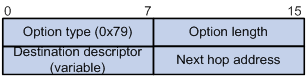
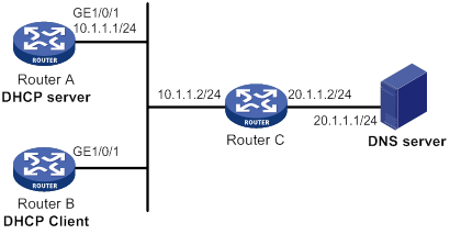
Configuration procedure
1. Configure Router A:
# Specify the IP address of GigabitEthernet 1/0/1.
<RouterA> system-view
[RouterA] interface gigabitethernet 1/0/1
[RouterA-GigabitEthernet1/0/1] ip address 10.1.1.1 24
[RouterA-GigabitEthernet1/0/1] quit
# Enable DHCP.
[RouterA] dhcp enable
# Exclude an IP address from dynamic allocation.
[RouterA] dhcp server forbidden-ip 10.1.1.2
# Configure DHCP address pool 0. Specify the subnet, lease duration, DNS server address, and a static route to subnet 20.1.1.0/24.
[RouterA] dhcp server ip-pool 0
[RouterA-dhcp-pool-0] network 10.1.1.0 mask 255.255.255.0
[RouterA-dhcp-pool-0] expired day 10
[RouterA-dhcp-pool-0] dns-list 20.1.1.1
[RouterA-dhcp-pool-0] option 121 hex 181401010A010102
2. Configure Router B:
# Configure GigabitEthernet 1/0/1 to use DHCP for IP address acquisition.
<RouterB> system-view
[RouterB] interface gigabitethernet 1/0/1
[RouterB-GigabitEthernet1/0/1] ip address dhcp-alloc
[RouterB-GigabitEthernet1/0/1] quit
Verifying the configuration
# Display the IP address and other network parameters assigned to Router B.
[RouterB] display dhcp client verbose
GigabitEthernet1/0/1 DHCP client information:
Current machine state: BOUND
Allocated IP: 10.1.1.3 255.255.255.0
Allocated lease: 864000 seconds, T1: 331858 seconds, T2: 756000 seconds
Lease from May 21 19:00:29 2012 to May 31 19:00:29 2012
DHCP server: 10.1.1.1
Transaction ID: 0xcde72232
Classless static route:
Destination: 20.1.1.0, Mask: 255.255.255.0, NextHop: 10.1.1.2
DNS server: 20.1.1.1
Client ID type: acsii(type value=00)
Client ID value: 000c.29d3.8659-GE1/0/1
Client ID (with type) hex: 0030-3030-632e-3239-
6433-2e38-3635-392d-
4574-6830-2f30-2f32
T1 will timeout in 3 days 19 hours 48 minutes 43 seconds.
# Display the route information on Router B. The output shows that a static route to subnet 20.1.1.0/24 is added to the routing table.
[RouterB] display ip routing-table
Destinations : 11 Routes : 11
Destination/Mask Proto Pre Cost NextHop Interface
10.1.1.0/24 Direct 0 0 10.1.1.3 GE1/0/1
10.1.1.3/32 Direct 0 0 127.0.0.1 InLoop0
20.1.1.0/24 Static 70 0 10.1.1.2 GE1/0/1
10.1.1.255/32 Direct 0 0 10.1.1.3 GE1/0/1
127.0.0.0/8 Direct 0 0 127.0.0.1 InLoop0
127.0.0.0/32 Direct 0 0 127.0.0.1 InLoop0
127.0.0.1/32 Direct 0 0 127.0.0.1 InLoop0
127.255.255.255/32 Direct 0 0 127.0.0.1 InLoop0
224.0.0.0/4 Direct 0 0 0.0.0.0 NULL0
224.0.0.0/24 Direct 0 0 0.0.0.0 NULL0
255.255.255.255/32 Direct 0 0 127.0.0.1 InLoop0
Configuring DHCP snooping
Overview
DHCP snooping works between the DHCP client and server, or between the DHCP client and DHCP relay agent. It guarantees that DHCP clients obtain IP addresses from authorized DHCP servers. Also, it records IP-to-MAC bindings of DHCP clients (called DHCP snooping entries) for security purposes.
DHCP snooping does not work between the DHCP server and DHCP relay agent.
DHCP snooping defines trusted and untrusted ports to make sure clients obtain IP addresses only from authorized DHCP servers.
· Trusted—A trusted port can forward DHCP messages correctly to make sure the clients get IP addresses from authorized DHCP servers.
· Untrusted—An untrusted port discards received DHCP-ACK and DHCP-OFFER messages to prevent unauthorized servers from assigning IP addresses.
DHCP snooping reads DHCP-ACK messages received from trusted ports and DHCP-REQUEST messages to create DHCP snooping entries. A DHCP snooping entry includes the MAC and IP addresses of a client, the port that connects to the DHCP client, and the VLAN.
The following features need to use DHCP snooping entries:
· ARP fast-reply—Uses DHCP snooping entries to reduce ARP broadcast traffic. For more information, see "Configuring ARP fast-reply."
· ARP detection—Uses DHCP snooping entries to filter ARP packets from unauthorized clients. For more information, see Security Configuration Guide.
· MAC-forced forwarding (MFF)—Auto-mode MFF performs the following tasks:
? Intercepts ARP requests from clients.
? Uses DHCP snooping entries to find the gateway address.
? Returns the gateway MAC address to the clients.
This feature forces the client to send all traffic to the gateway so that the gateway can monitor client traffic to prevent malicious attacks among clients.
· IP source guard—Uses DHCP snooping entries to filter illegal packets on a per-port basis. For more information, see Security Configuration Guide.
· VLAN mapping—Uses DHCP snooping entries to replace service provider VLAN in packets with customer VLAN before sending the packets to clients.
Application of trusted and untrusted ports
Configure ports facing the DHCP server as trusted ports, and configure other ports as untrusted ports.
As shown in Figure 35, configure the DHCP snooping device's port that is connected to the DHCP server as a trusted port. The trusted port forwards response messages from the DHCP server to the client. The untrusted port connected to the unauthorized DHCP server discards incoming DHCP response messages.
Figure 35 Trusted and untrusted ports
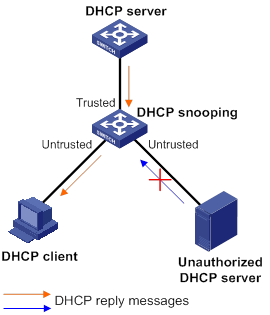
In a cascaded network as shown in Figure 36, configure the DHCP snooping devices' ports facing the DHCP server as trusted ports. To save system resources, you can enable only the untrusted ports directly connected to the DHCP clients to record DHCP snooping entries.
Figure 36 Trusted and untrusted ports in a cascaded network
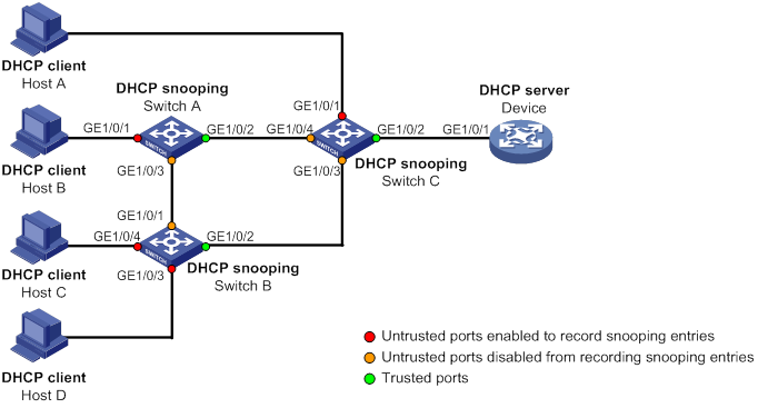
DHCP snooping support for Option 82
Option 82 records the location information about the DHCP client so the administrator can locate the DHCP client for security and accounting purposes. For more information about Option 82, see "Relay agent option (Option 82)."
DHCP snooping uses the same strategies as the DHCP relay agent to handle Option 82 for DHCP request messages, as shown in Table 5. If a response returned by the DHCP server contains Option 82, DHCP snooping removes Option 82 before forwarding the response to the client. If the response contains no Option 82, DHCP snooping forwards it directly.
|
If a DHCP request has… |
Handling strategy |
DHCP snooping… |
|
Option 82 |
Drop |
Drops the message. |
|
Keep |
Forwards the message without changing Option 82. |
|
|
Replace |
Forwards the message after replacing the original Option 82 with the Option 82 padded according to the configured padding format, padding content, and code type. |
|
|
No Option 82 |
N/A |
Forwards the message after adding the Option 82 padded according to the configured padding format, padding content, and code type. |
Feature and hardware compatibility
|
Hardware |
DHCP snooping compatibility |
|
MSR810/810-W/810-W-DB/810-LM/810-W-LM/810-10-PoE /810-LM-HK/MSR810-W-LM-HK |
Yes |
|
MSR810-LMS/810-LUS |
No |
|
MSR2600-6-X1/2600-10-X1 |
Yes |
|
MSR 2630 |
Yes |
|
MSR3600-28/3600-51 |
Yes |
|
MSR3600-28-SI/3600-51-SI |
Yes |
|
MSR3610-X1/3610-X1-DP/3610-X1-DC/3610-X1-DP-DC |
Yes |
|
MSR 3610/3620/3620-DP/3640/3660 |
Yes |
|
MSR 5620/5660/5680 |
Yes |
|
Hardware |
DHCP snooping compatibility |
|
MSR810-LM-GL |
No |
|
MSR810-W-LM-GL |
No |
|
MSR830-6EI-GL |
No |
|
MSR830-10EI-GL |
No |
|
MSR830-6HI-GL |
No |
|
MSR830-10HI-GL |
No |
|
MSR2600-6-X1-GL |
No |
|
MSR3600-28-SI-GL |
Yes |
DHCP snooping configuration task list
The DHCP snooping configuration does not take effect on a Layer 2 Ethernet interface that is an aggregation member port. The configuration takes effect when the interface leaves the aggregation group.
|
Tasks at a glance |
|
(Required.) Configuring basic DHCP snooping |
|
(Optional.) Configuring Option 82 |
|
(Optional.) Configuring DHCP snooping entry auto backup |
|
(Optional.) Enabling DHCP starvation attack protection |
|
(Optional.) Enabling DHCP-REQUEST attack protection |
|
(Optional.) Setting the maximum number of DHCP snooping entries |
|
(Optional.) Configuring a DHCP packet blocking port |
|
(Optional.) Enabling DHCP snooping logging |
Configuring basic DHCP snooping
Follow these guidelines when you configure basic DHCP snooping:
· Specify the ports connected to authorized DHCP servers as trusted ports to make sure that DHCP clients can obtain valid IP addresses. The trusted ports and the ports connected to DHCP clients must be in the same VLAN.
· You can specify the following interfaces as trusted ports: Layer 2 Ethernet interfaces and Layer 2 aggregate interfaces. For more information about aggregate interfaces, see Layer 2—LAN Switching Configuration Guide.
· The DHCP snooping configuration on a Layer 2 Ethernet interface that has been added to an aggregation group does not take effect unless the interface leaves the aggregation group.
· DHCP snooping can work with QinQ to record VLAN tags for DHCP packets received from clients. For more information about QinQ, see Layer 2—LAN Switching Configuration Guide.
To configure basic DHCP snooping:
|
Step |
Command |
Remarks |
|
1. Enter system view. |
system-view |
N/A |
|
2. Enable DHCP snooping. |
dhcp snooping enable |
By default, DHCP snooping is disabled. |
|
3. Enter interface view. |
interface interface-type interface-number |
This interface must connect to the DHCP server. |
|
4. Specify the port as a trusted port. |
dhcp snooping trust |
By default, all ports are untrusted ports after DHCP snooping is enabled. |
|
5. Return to system view. |
quit |
N/A |
|
6. Enter interface view. |
interface interface-type interface-number |
This interface must connect to the DHCP client. |
|
7. (Optional.) Enable the recording of DHCP snooping entries. |
By default, the recording of DHCP snooping entries is disabled. |
Configuring Option 82
Follow these guidelines when you configure Option 82:
· The Option 82 configuration on a Layer 2 Ethernet interface that has been added to an aggregation group does not take effect unless the interface leaves the aggregation group.
· To support Option 82, you must configure Option 82 on both the DHCP server and the DHCP snooping device. For information about configuring Option 82 on the DHCP server, see "Enabling handling of Option 82."
· If the handling strategy is replace, configure a padding mode and padding format for Option 82. If the handling strategy is keep or drop, you do not need to configure any padding mode or padding format for Option 82. The settings do not take effect even if you configure them.
· If Option 82 contains the device name, the device name must contain no spaces. Otherwise, DHCP snooping drops the message. You can use the sysname command to specify the device name. For more information about this command, see Fundamentals Command Reference.
· DHCP snooping uses "outer VLAN tag.inner VLAN tag" to fill the VLAN ID field of sub-option 1 in verbose padding format if either of the following conditions exists:
? DHCP snooping and QinQ work together.
? DHCP snooping receives a DHCP packet with two VLAN tags.
For example, if the outer VLAN tag is 10 and the inner VLAN tag is 20, the VLAN ID field is 000a.0014. The hexadecimal digit a represents the outer VLAN tag 10, and the hexadecimal digit 14 represents the inner VLAN tag 20.
· The device name (sysname) must not include spaces if it is configured as the padding content for sub-option 1. Otherwise, the DHCP snooping device will fail to add or replace Option 82.
To configure DHCP snooping to support Option 82:
|
Step |
Command |
Remarks |
|
1. Enter system view. |
system-view |
N/A |
|
2. Enter interface view. |
interface interface-type interface-number |
N/A |
|
3. Enable DHCP snooping to support Option 82. |
dhcp snooping information enable |
By default, DHCP snooping does not support Option 82. |
|
4. (Optional.) Configure a handling strategy for DHCP requests that contain Option 82. |
dhcp snooping information strategy { drop | keep | replace } |
By default, the handling strategy is replace. |
|
5. (Optional.) Configure the padding mode and padding format for the Circuit ID sub-option. |
dhcp snooping information circuit-id { [ vlan vlan-id ] string circuit-id | { normal | verbose [ node-identifier { mac | sysname | user-defined node-identifier } ] } [ format { ascii | hex } ] } |
By default, the padding mode is normal and the padding format is hex for the Circuit ID sub-option. |
|
6. (Optional.) Configure the padding mode and padding format for the Remote ID sub-option. |
dhcp snooping information remote-id { normal [ format { ascii | hex } ] | [ vlan vlan-id ] string remote-id | sysname } |
By default, the padding mode is normal and the padding format is hex for the Remote ID sub-option. |
Configuring DHCP snooping entry auto backup
The auto backup feature saves DHCP snooping entries to a backup file, and allows the DHCP snooping device to download the entries from the backup file at device reboot. The entries on the DHCP snooping device cannot survive a reboot. The auto backup helps the security features provide services if these features (such as IP source guard) must use DHCP snooping entries for user authentication.
|
|
NOTE: If you disable DHCP snooping with the undo dhcp snooping enable command, the device deletes all DHCP snooping entries, including those stored in the backup file. |
To save DHCP snooping entries:
|
Step |
Command |
Remarks |
|
1. Enter system view. |
system-view |
N/A |
|
2. Configure the DHCP snooping device to back up DHCP snooping entries to a file. |
dhcp snooping binding database filename { filename | url url [ username username [ password { cipher | simple } string ] ] } |
By default, the DHCP snooping device does not back up DHCP snooping entries. With this command executed, the DHCP snooping device backs up DHCP snooping entries immediately and runs auto backup. This command automatically creates the file if you specify a non-existent file. |
|
3. (Optional.) Manually save DHCP snooping entries to the backup file. |
dhcp snooping binding database update now |
N/A |
|
4. (Optional.) Set the waiting time after a DHCP snooping entry change for the DHCP snooping device to update the backup file. |
dhcp snooping binding database update interval interval |
The default waiting time is 300 seconds. When a DHCP snooping entry is learned, updated, or removed, the waiting period starts. The DHCP snooping device updates the backup file when the specified waiting period is reached. All changed entries during the period will be saved to the backup file. If no DHCP snooping entry changes, the backup file is not updated. |
Enabling DHCP starvation attack protection
A DHCP starvation attack occurs when an attacker constantly sends forged DHCP requests that contain identical or different sender MAC addresses in the chaddr field to a DHCP server. This attack exhausts the IP address resources of the DHCP server so legitimate DHCP clients cannot obtain IP addresses. The DHCP server might also fail to work because of exhaustion of system resources. For information about the fields of DHCP packet, see "DHCP message format."
You can prevent DHCP starvation attacks in the following ways:
· If the forged DHCP requests contain different sender MAC addresses, use the mac-address max-mac-count command to limit the number of MAC addresses that a Layer 2 port can learn. For more information about the command, see Layer 2—LAN Switching Command Reference.
· If the forged DHCP requests contain the same sender MAC address, perform this task to enable MAC address check for DHCP snooping. This feature compares the chaddr field of a received DHCP request with the source MAC address field in the frame header. If they are the same, the request is considered valid and forwarded to the DHCP server. If not, the request is discarded.
To enable MAC address check:
|
Step |
Command |
Remarks |
|
1. Enter system view. |
system-view |
N/A |
|
2. Enter interface view. |
interface interface-type interface-number |
N/A |
|
3. Enable MAC address check. |
dhcp snooping check mac-address |
By default, MAC address check is disabled. |
Enabling DHCP-REQUEST attack protection
DHCP-REQUEST messages include DHCP lease renewal packets, DHCP-DECLINE packets, and DHCP-RELEASE packets. This feature prevents the unauthorized clients that forge the DHCP-REQUEST messages from attacking the DHCP server.
Attackers can forge DHCP lease renewal packets to renew leases for legitimate DHCP clients that no longer need the IP addresses. These forged messages disable the victim DHCP server from releasing the IP addresses.
Attackers can also forge DHCP-DECLINE or DHCP-RELEASE packets to terminate leases for legitimate DHCP clients that still need the IP addresses.
To prevent such attacks, you can enable DHCP-REQUEST check. This feature uses DHCP snooping entries to check incoming DHCP-REQUEST messages.
· If a matching entry is found for a message, this feature compares the entry with the message information.
? If they are consistent, the message is considered as valid and forwarded to the DHCP server.
? If they are different, the message is considered as a forged message and is discarded.
· If no matching entry is found, the message is considered valid and forwarded to the DHCP server.
To enable DHCP-REQUEST attack protection:
|
Step |
Command |
Remarks |
|
1. Enter system view. |
system-view |
N/A |
|
2. Enter interface view. |
interface interface-type interface-number |
N/A |
|
3. Enable DHCP-REQUEST check. |
dhcp snooping check request-message |
By default, DHCP-REQUEST check is disabled. You can enable DHCP-REQUEST check only on Layer 2 Ethernet interfaces and Layer 2 aggregate interfaces. |
Setting the maximum number of DHCP snooping entries
Perform this task to prevent the system resources from being overused.
To set the maximum number of DHCP snooping entries:
|
Step |
Command |
Remarks |
|
1. Enter system view. |
system-view |
N/A |
|
2. Enter interface view. |
interface interface-type interface-number |
N/A |
|
3. Set the maximum number of DHCP snooping entries for the interface to learn. |
dhcp snooping max-learning-num max-number |
By default, the number of DHCP snooping entries for an interface to learn is unlimited. |
Configuring a DHCP packet blocking port
Perform this task to configure a port as a DHCP packet blocking port. This blocking port drops all incoming DHCP requests.
To configure a DHCP packet blocking port:
|
Step |
Command |
Remarks |
|
1. Enter system view. |
system-view |
N/A |
|
2. Enter interface view. |
interface interface-type interface-number |
N/A |
|
3. Configure the port to block DHCP requests. |
dhcp snooping deny |
By default, the port does not block DHCP requests. |
Enabling DHCP snooping logging
The DHCP snooping logging feature enables the DHCP snooping device to generate DHCP snooping logs and send them to the information center. For information about the log destination and output rule configuration in the information center, see Network Management and Monitoring Configuration Guide.
As a best practice, disable this feature if the log generation affects the device performance.
To enable DHCP snooping logging:
|
Step |
Command |
Remarks |
|
1. Enter system view. |
system-view |
N/A |
|
2. Enable DHCP snooping logging. |
dhcp snooping log enable |
By default, DHCP snooping logging is disabled. |
Displaying and maintaining DHCP snooping
Execute display commands in any view, and reset commands in user view.
|
Task |
Command |
Remarks |
|
Display DHCP snooping entries. |
display dhcp snooping binding [ ip ip-address [ vlan vlan-id ] ] |
Available in any view. |
|
Display Option 82 configuration information on the DHCP snooping device. |
display dhcp snooping information { all | interface interface-type interface-number } |
Available in any view. |
|
Display DHCP packet statistics on the DHCP snooping device (centralized devices in standalone mode). |
display dhcp snooping packet statistics |
Available in any view. |
|
Display DHCP packet statistics on the DHCP snooping device (distributed devices in standalone mode/centralized devices in IRF mode). |
display dhcp snooping packet statistics [ slot slot-number ] |
Available in any view. |
|
Display DHCP packet statistics on the DHCP snooping device (distributed devices in IRF mode). |
display dhcp snooping packet statistics [ chassis chassis-number slot slot-number ] |
Available in any view. |
|
Display information about trusted ports. |
display dhcp snooping trust |
Available in any view. |
|
Display information about the file that stores DHCP snooping entries. |
display dhcp snooping binding database |
Available in any view. |
|
Clear DHCP snooping entries. |
reset dhcp snooping binding { all | ip ip-address [ vlan vlan-id ] } |
Available in user view. |
|
Clear DHCP packet statistics on the DHCP snooping device (centralized devices in standalone mode). |
reset dhcp snooping packet statistics |
Available in user view. |
|
Clear DHCP packet statistics on the DHCP snooping device (distributed devices in standalone mode/centralized devices in IRF mode). |
reset dhcp snooping packet statistics [ slot slot-number ] |
Available in user view. |
|
Clear DHCP packet statistics on the DHCP snooping device (distributed devices in IRF mode). |
reset dhcp snooping packet statistics [ chassis chassis-number slot slot-number ] |
Available in user view. |
DHCP snooping configuration examples
Basic DHCP snooping configuration example
Network requirements
As shown in Figure 37:
· Configure the port GigabitEthernet 1/0/1 connected to the DHCP server as a trusted port.
· Configure other ports as untrusted ports.
· Enable DHCP snooping to record clients' IP-to-MAC bindings by reading DHCP-ACK messages received from the trusted port and DHCP-REQUEST messages.
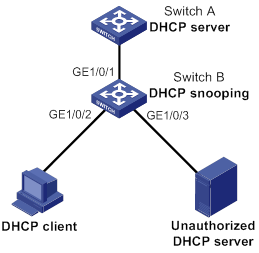
Configuration procedure
# Enable DHCP snooping.
<SwitchB> system-view
[SwitchB] dhcp snooping enable
# Configure GigabitEthernet 1/0/1 as a trusted port.
[SwitchB] interface gigabitethernet 1/0/1
[SwitchB-GigabitEthernet1/0/1] dhcp snooping trust
[SwitchB-GigabitEthernet1/0/1] quit
# Enable DHCP snooping to record clients' IP-to-MAC bindings on GigabitEthernet 1/0/2.
[SwitchB] interface gigabitethernet 1/0/2
[SwitchB-GigabitEthernet1/0/2] dhcp snooping binding record
[SwitchB-GigabitEthernet1/0/2] quit
Verifying the configuration
# Verify that the DHCP client can obtain an IP address and other configuration parameters only from the authorized DHCP server. (Details not shown.)
# Display the DHCP snooping entry recorded for the client.
[SwitchB] display dhcp snooping binding
Option 82 configuration example
Network requirements
As shown in Figure 38, enable DHCP snooping and configure Option 82 on Switch B as follows:
· Configure the handling strategy for DHCP requests that contain Option 82 as replace.
· On GigabitEthernet 1/0/2, configure the padding content for the Circuit ID sub-option as company001 and for the Remote ID sub-option as device001.
· On GigabitEthernet 1/0/3, configure the padding mode for the Circuit ID sub-option as verbose, access node identifier as sysname, and padding format as ascii. Configure the padding content for the Remote ID sub-option as device001.
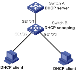
Configuration procedure
# Enable DHCP snooping.
<SwitchB> system-view
[SwitchB] dhcp snooping enable
# Configure GigabitEthernet 1/0/1 as a trusted port.
[SwitchB] interface gigabitethernet 1/0/1
[SwitchB-GigabitEthernet1/0/1] dhcp snooping trust
[SwitchB-GigabitEthernet1/0/1] quit
# Configure Option 82 on GigabitEthernet 1/0/2.
[SwitchB] interface gigabitethernet 1/0/2
[SwitchB-GigabitEthernet1/0/2] dhcp snooping information enable
[SwitchB-GigabitEthernet1/0/2] dhcp snooping information strategy replace
[SwitchB-GigabitEthernet1/0/2] dhcp snooping information circuit-id string company001
[SwitchB-GigabitEthernet1/0/2] dhcp snooping information remote-id string device001
[SwitchB-GigabitEthernet1/0/2] quit
# Configure Option 82 on GigabitEthernet 1/0/3.
[SwitchB] interface gigabitethernet 1/0/3
[SwitchB-GigabitEthernet1/0/3] dhcp snooping information enable
[SwitchB-GigabitEthernet1/0/3] dhcp snooping information strategy replace
[SwitchB-GigabitEthernet1/0/3] dhcp snooping information circuit-id verbose node-identifier sysname format ascii
[SwitchB-GigabitEthernet1/0/3] dhcp snooping information remote-id string device001
Verifying the configuration
# Display Option 82 configuration information on GigabitEthernet 1/0/2 and GigabitEthernet 1/0/3 on the DHCP snooping device.
[SwitchB] display dhcp snooping information
Configuring the BOOTP client
BOOTP client configuration applies only to Layer 3 Ethernet interfaces (including subinterfaces), Layer 3 aggregate interfaces, and VLAN interfaces.
BOOTP application
An interface that acts as a BOOTP client can use BOOTP to obtain information (such as IP address) from the BOOTP server.
To use BOOTP, an administrator must configure a BOOTP parameter file for each BOOTP client on the BOOTP server. The parameter file contains information such as MAC address and IP address of a BOOTP client. When a BOOTP client sends a request to the BOOTP server, the BOOTP server searches for the BOOTP parameter file and returns the corresponding configuration information.
BOOTP is usually used in relatively stable environments. In network environments that change frequently, DHCP is more suitable.
Because a DHCP server can interact with a BOOTP client, you can use the DHCP server to assign an IP address to the BOOTP client. You do not need to configure a BOOTP server.
Obtaining an IP address dynamically
A BOOTP client dynamically obtains an IP address from a BOOTP server as follows:
1. The BOOTP client broadcasts a BOOTP request, which contains its own MAC address.
2. Upon receiving the request, the BOOTP server searches the configuration file for the IP address and other information according to the BOOTP client's MAC address.
3. The BOOTP server returns a BOOTP response to the BOOTP client.
4. The BOOTP client obtains the IP address from the received response.
A DHCP server can take the place of the BOOTP server in the following dynamic IP address acquisition.
Protocols and standards
· RFC 951, Bootstrap Protocol (BOOTP)
· RFC 2132, DHCP Options and BOOTP Vendor Extensions
· RFC 1542, Clarifications and Extensions for the Bootstrap Protocol
Configuring an interface to use BOOTP for IP address acquisition
|
Step |
Command |
Remarks |
|
1. Enter system view. |
system-view |
N/A |
|
2. Enter interface view. |
interface interface-type interface-number |
N/A |
|
3. Configure an interface to use BOOTP for IP address acquisition. |
ip address bootp-alloc |
By default, an interface does not use BOOTP for IP address acquisition. |
Displaying and maintaining BOOTP client
Execute display command in any view.
|
Task |
Command |
|
Display BOOTP client information. |
display bootp client [ interface interface-type interface-number ] |
BOOTP client configuration example
Network requirements
As shown in Figure 25, GigabitEthernet 1/0/1 of Router B connects to the LAN to obtain an IP address from the DHCP server by using BOOTP.
To make the BOOTP client obtain an IP address from the DHCP server, perform configuration on the DHCP server. For more information, see "DHCP server configuration examples."
Configuration procedure
The following describes the configuration on Router B, which acts as a client.
# Configure GigabitEthernet 1/0/1 to use BOOTP to obtain an IP address.
<RouterB> system-view
[RouterB] interface gigabitethernet 1/0/1
[RouterB-GigabitEthernet1/0/1] ip address bootp-alloc
Verifying the configuration
# Display the IP address assigned to the BOOTP client.
[RouterB] display bootp client
Configuring DNS
Overview
Domain Name System (DNS) is a distributed database used by TCP/IP applications to translate domain names into IP addresses. The domain name-to-IP address mapping is called a DNS entry.
DNS services can be static or dynamic. After a user specifies a name, the device checks the static name resolution table for an IP address. If no IP address is available, it contacts the DNS server for dynamic name resolution, which takes more time than static name resolution. To improve efficiency, you can put frequently queried name-to-IP address mappings in the local static name resolution table.
Static domain name resolution
Static domain name resolution means manually creating mappings between domain names and IP addresses. For example, you can create a static DNS mapping for a device so that you can Telnet to the device by using the domain name.
Dynamic domain name resolution
Resolution process
1. A user program sends a name query to the resolver of the DNS client.
2. The DNS resolver looks up the local domain name cache for a match. If the resolver finds a match, it sends the corresponding IP address back. If not, it sends a query to the DNS server.
3. The DNS server looks up the corresponding IP address of the domain name in its DNS database. If no match is found, the server sends a query to other DNS servers. This process continues until a result, whether successful or not, is returned.
4. After receiving a response from the DNS server, the DNS client returns the resolution result to the user program.
Figure 39 shows the relationship between the user program, DNS client, and DNS server.
The DNS client includes the resolver and cache. The user program and DNS client can run on the same device or different devices. The DNS server and the DNS client usually run on different devices.
Figure 39 Dynamic domain name resolution
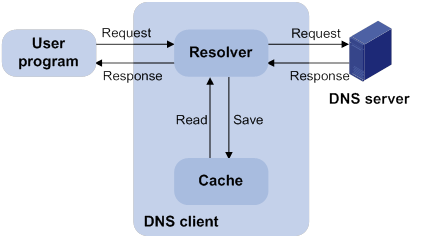
Dynamic domain name resolution allows the DNS client to store latest DNS entries in the dynamic domain name cache. The DNS client does not need to send a request to the DNS server for a repeated query within the aging time. To make sure the entries from the DNS server are up to date, a DNS entry is removed when its aging timer expires. The DNS server determines how long a mapping is valid, and the DNS client obtains the aging information from DNS responses.
DNS suffixes
You can configure a domain name suffix list so that the resolver can use the list to supply the missing part of an incomplete name.
For example, you can configure com as the suffix for aabbcc.com. The user only needs to enter aabbcc to obtain the IP address of aabbcc.com. The resolver adds the suffix and delimiter before passing the name to the DNS server.
The name resolver handles the queries based on the domain names that the user enters:
· If the user enters a domain name without a dot (.) (for example, aabbcc), the resolver considers the domain name to be a host name. It adds a DNS suffix to the host name before performing the query operation. If no match is found for any host name and suffix combination, the resolver uses the user-entered domain name (for example, aabbcc) for the IP address query.
· If the user enters a domain name with a dot (.) among the letters (for example, www.aabbcc), the resolver directly uses this domain name for the query operation. If the query fails, the resolver adds a DNS suffix for another query operation.
· If the user enters a domain name with a dot (.) at the end (for example, aabbcc.com.), the resolver considers the domain name an FQDN and returns the successful or failed query result. The dot at the end of the domain name is considered a terminating symbol.
The device supports static and dynamic DNS client services.
If an alias is configured for a domain name on the DNS server, the device can resolve the alias into the IP address of the host.
DNS proxy
As shown in Figure 40, the DNS proxy performs the following operations:
· Forwards the request from the DNS client to the designated DNS server.
· Conveys the reply from the DNS server to the client.
The DNS proxy simplifies network management. When the DNS server address is changed, you can change the configuration only on the DNS proxy instead of on each DNS client.
Figure 40 DNS proxy application
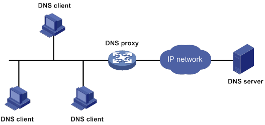
A DNS proxy operates as follows:
1. A DNS client considers the DNS proxy as the DNS server, and sends a DNS request to the DNS proxy. The destination address of the request is the IP address of the DNS proxy.
2. The DNS proxy searches the local static domain name resolution table and dynamic domain name resolution cache after receiving the request. If the requested information is found, the DNS proxy returns a DNS reply to the client.
3. If the requested information is not found, the DNS proxy sends the request to the designated DNS server for domain name resolution.
4. After receiving a reply from the DNS server, the DNS proxy records the IP address-to-domain name mapping and forwards the reply to the DNS client.
If no DNS server is designated or no route is available to the designated DNS server, the DNS proxy does not forward DNS requests.
DNS spoofing
DNS spoofing is applied to the dial-up network, as shown in Figure 41.
· The device connects to a PSTN/ISDN network through a dial-up interface. The device triggers the establishment of a dial-up connection only when packets are to be forwarded through the dial-up interface.
· The device acts as a DNS proxy and is specified as a DNS server on the hosts. After the dial-up connection is established, the device dynamically obtains the DNS server address through DHCP or another autoconfiguration mechanism.
Figure 41 DNS spoofing application
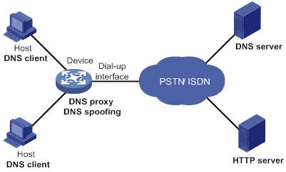
The DNS proxy does not have the DNS server address or cannot reach the DNS server after startup. A host accesses the HTTP server in the following steps:
1. The host sends a DNS request to the device to resolve the domain name of the HTTP server into an IP address.
2. Upon receiving the request, the device searches the local static and dynamic DNS entries for a match. Because no match is found, the device spoofs the host by replying a configured IP address. The device must have a route to the IP address with the dial-up interface as the output interface.
The IP address configured for DNS spoofing is not the actual IP address of the requested domain name. Therefore, the TTL field is set to 0 in the DNS reply. When the DNS client receives the reply, it creates a DNS entry and ages it out immediately.
3. Upon receiving the reply, the host sends an HTTP request to the replied IP address.
4. When forwarding the HTTP request through the dial-up interface, the device performs the following operations:
? Establishes a dial-up connection with the network.
? Dynamically obtains the DNS server address through DHCP or another autoconfiguration mechanism.
5. Because the DNS entry ages out immediately upon creation, the host sends another DNS request to the device to resolve the HTTP server domain name.
6. The device operates the same as a DNS proxy. For more information, see "DNS proxy."
7. After obtaining the IP address of the HTTP server, the host can access the HTTP server.
Without DNS spoofing, the device forwards the DNS requests from the host to the DNS server if it cannot find a matching local DNS entry. However, the device cannot obtain the DNS server address, because no dial-up connection is established. Therefore, the device cannot forward or answer the requests from the client. DNS resolution fails, and the client cannot access the HTTP server.
Feature and hardware compatibility
IPv6-related features are not supported on the following routers:
· MSR810/810-W/810-W-DB/810-LM/810-W-LM/810-10-PoE/810-LM-HK/810-W-LM-HK/810-LMS/810-LUS.
· MSR3600-28-SI/3600-51-SI.
DNS configuration task list
|
Tasks at a glance |
|
Perform one of the following tasks: |
|
(Optional.) Configuring the DNS proxy |
|
(Optional.) Configuring DNS spoofing |
|
(Optional.) Configuring network mode tracking for an output interface |
|
(Optional.) Specifying the source interface for DNS packets |
|
(Optional.) Configuring the DNS trusted interface |
|
(Optional.) Setting the DSCP value for outgoing DNS packets |
Configuring the IPv4 DNS client
Configuring static domain name resolution
Static domain name resolution allows applications such as Telnet to contact hosts by using host names instead of IPv4 addresses.
Follow these guidelines when you configure static domain name resolution:
· For the public network or a VPN instance, each host name maps to only one IPv4 address. The most recent configuration for a host name takes effect.
· You can configure the following:
? IPv4 DNS entries for both public network and VPN instances.
? A maximum of 1024 IPv4 DNS entries for the public network or each VPN instance.
To configure static domain name resolution:
|
Step |
Command |
Remarks |
|
1. Enter system view. |
system-view |
N/A |
|
2. Configure a host name-to-IPv4 address mapping. |
ip host host-name ip-address [ vpn-instance vpn-instance-name ] |
By default, no host name-to-IPv4 address mappings exist. |
Configuring dynamic domain name resolution
To use dynamic domain name resolution, a DNS server address is required so that DNS queries can be sent to a correct server for resolution.
In addition, you can configure a DNS suffix that the system automatically adds to the incomplete domain name that a user enters.
Configuration guidelines
Follow these guidelines when you configure dynamic domain name resolution:
· In system view, you can specify a maximum of six DNS server IPv4 addresses for the public network or each VPN instance. You can specify DNS server IPv4 addresses for both public network and VPN instances.
· In system view, you can specify a maximum of six DNS server IPv6 addresses for the public network or each VPN instance. You can specify DNS server IPv6 addresses for both public network and VPN instances.
· In interface view, you can specify a maximum of six DNS server IPv4 addresses for the public network or each VPN instance. You can specify DNS server IPv4 addresses for both public network and VPN instances.
· An IPv4 DNS query is first sent to the DNS server IPv4 addresses. If no reply is received, it is sent to the DNS server IPv6 addresses.
· A DNS server address specified in system view takes priority over a DNS server address specified in interface view. A DNS server address specified earlier has a higher priority. A DNS server address manually specified takes priority over a DNS server address dynamically obtained, for example, through DHCP. The device first sends a DNS query to the DNS server address of the highest priority. If the first query fails, it sends the DNS query to the DNS server address of the second highest priority, and so on.
· You can configure a maximum of 16 DNS suffixes for the public network or each VPN instance. You can configure DNS suffixes for both public network and VPN instances.
· A DNS suffix manually configured takes priority over a DNS suffix dynamically obtained, for example, through DHCP. A DNS suffix configured earlier has a higher priority. The device first uses the suffix that has the highest priority. If the query fails, the device uses the suffix that has the second highest priority, and so on.
Configuration procedure
To configure dynamic domain name resolution:
|
Step |
Command |
Remarks |
|
1. Enter system view. |
system-view |
N/A |
|
2. (Optional.) Configure a DNS suffix. |
dns domain domain-name [ vpn-instance vpn-instance-name ] |
By default, no DNS suffix is configured and only the domain name that a user enters is resolved. |
|
3. Specify a DNS server IPv4 address in system view. |
dns server ip-address [ vpn-instance vpn-instance-name ] |
Perform one or more of the tasks. By default, no DNS server address is specified. |
|
4. Specify a DNS server IPv4 address in interface view. |
a
Enter interface view: b
Specify a DNS server IPv4 address: |
|
|
5. Specify a DNS server IPv6 address. |
ipv6 dns server ipv6-address [ interface-type interface-number ] [ vpn-instance vpn-instance-name ] |
Configuring the IPv6 DNS client
Configuring static domain name resolution
Static domain name resolution allows applications such as Telnet to contact hosts by using host names instead of IPv6 addresses.
Follow these guidelines when you configure static domain name resolution:
· For the public network or a VPN instance, each host name maps to only one IPv6 address. The most recent configuration for a host name takes effect.
· You can configure the following items:
? IPv6 DNS entries for both public network and VPN instances.
? A maximum of 1024 IPv6 DNS entries for the public network or each VPN instance.
To configure static domain name resolution:
|
Step |
Command |
Remarks |
|
1. Enter system view. |
system-view |
N/A |
|
2. Configure a host name-to-IPv6 address mapping. |
ipv6 host host-name ipv6-address [ vpn-instance vpn-instance-name ] |
By default, no host name-to-IPv6 address mappings exist. |
Configuring dynamic domain name resolution
To use dynamic domain name resolution, a DNS server address is required so that DNS queries can be sent to a correct server for resolution.
In addition, you can configure a DNS suffix that the system automatically adds to the incomplete domain name that a user enters.
Configuration guidelines
Follow these guidelines when you configure dynamic domain name resolution:
· In system view, you can specify a maximum of six DNS server IPv4 addresses for the public network or each VPN instance. You can specify DNS server IPv4 addresses for both public network and VPN instances.
· In system view, you can specify a maximum of six DNS server IPv6 addresses for the public network or each VPN instance. You can specify DNS server IPv6 addresses for both public network and VPN instances.
· In interface view, you can specify a maximum of six DNS server IPv4 addresses for the public network or each VPN instance. You can specify DNS server IPv4 addresses for both public network and VPN instances.
· An IPv6 DNS query is first sent to the DNS server IPv6 addresses. If no reply is received, it is sent to the DNS server IPv4 addresses.
· A DNS server address specified in system view takes priority over a DNS server address specified in interface view. A DNS server address specified earlier has a higher priority. A DNS server address manually specified takes priority over a DNS server address dynamically obtained, for example, through DHCP. The device first sends a DNS query to the DNS server address of the highest priority. If the first query fails, it sends the DNS query to the DNS server address of the second highest priority, and so on.
· You can configure a maximum of 16 DNS suffixes for the public network or each VPN instance. You can configure DNS suffixes for both public network and VPN instances.
· A DNS suffix manually configured takes priority over a DNS suffix dynamically obtained, for example, through DHCP. A DNS suffix configured earlier has a higher priority. The device first uses the suffix that has the highest priority. If the query fails, the device uses the suffix that has the second highest priority, and so on.
Configuration procedure
To configure dynamic domain name resolution:
|
Step |
Command |
Remarks |
|
1. Enter system view. |
system-view |
N/A |
|
2. (Optional.) Configure a DNS suffix. |
dns domain domain-name [ vpn-instance vpn-instance-name ] |
By default, no DNS suffix is configured and only the domain name that a user enters is resolved. |
|
3. Specify a DNS server IPv4 address in system view. |
dns server ip-address [ vpn-instance vpn-instance-name ] |
Perform one or more of the tasks. By default, no DNS server address is specified. |
|
4. Specify a DNS server IPv4 address in interface view. |
a
Enter interface view: b
Specify a DNS server IPv4 address: |
|
|
5. Specify a DNS server IPv6 address. |
ipv6 dns server ipv6-address [ interface-type interface-number ] [ vpn-instance vpn-instance-name ] |
Configuring the DNS proxy
You can specify multiple DNS servers. The DNS proxy forwards a request to the DNS server that has the highest priority. If having not received a reply, it forwards the request to a DNS server that has the second highest priority, and so on.
A DNS proxy forwards an IPv4 name query first to IPv4 DNS servers. If no reply is received, it forwards the request to IPv6 DNS servers.
A DNS proxy forwards an IPv6 name query first to IPv6 DNS servers. If no reply is received, it forwards the request to IPv4 DNS servers.
To configure the DNS proxy:
|
Step |
Command |
Remarks |
|
1. Enter system view. |
system-view |
N/A |
|
2. Enable DNS proxy. |
dns proxy enable |
By default, DNS proxy is disabled. |
|
3. Specify a DNS server IPv4 address in system view. |
dns server ip-address [ vpn-instance vpn-instance-name ] |
Perform one or more of the tasks. By default, no DNS server address is specified. |
|
4. Specify a DNS server IPv4 address in interface view. |
a
Enter interface view: b
Specify a DNS server IPv4 address: |
|
|
5. Specify a DNS server IPv6 address. |
ipv6 dns server ipv6-address [ interface-type interface-number ] [ vpn-instance vpn-instance-name ] |
Configuring DNS spoofing
DNS spoofing is effective only when:
· The DNS proxy is enabled on the device.
· No DNS server or route to any DNS server is specified on the device.
Follow these guidelines when you configure DNS spoofing:
· You can configure only one replied IPv4 address and one replied IPv6 address for the public network or a VPN instance. If you use the command multiple times, the most recent configuration takes effect.
· You can configure DNS spoofing for both public network and VPN instances.
· After DNS spoofing takes effect, the device spoofs a DNS request even though a matching static DNS entry exists.
To configure DNS spoofing:
|
Step |
Command |
Remarks |
|
1. Enter system view. |
system-view |
N/A |
|
2. Enable DNS proxy. |
dns proxy enable |
By default, DNS proxy is disabled. |
|
3. Enable DNS spoofing and specify the IP address used to spoof DNS requests. |
·
Specify an IPv4 address: ·
Specify an IPv6 address: |
By default, DNS spoofing is disabled. You can specify both an IPv4 address and an IPv6 address. |
Configuring network mode tracking for an output interface
This feature tracks the network mode of an output interface and spoofs DNS requests if the network mode is 2G. This feature takes effect on the cellular interface when the interface acts as the output interface to reach the DNS server. Spoofing DNS requests avoids DNS packet loss that might be caused by limited 2G network bandwidth.
To configure network mode tracking for an output interface:
|
Step |
Command |
Remarks |
|
1. Enter system view. |
system-view |
N/A |
|
2. Enable DNS proxy. |
dns proxy enable |
By default, DNS proxy is disabled. |
|
3. Enable DNS spoofing and specify the IP address used to spoof DNS requests. |
·
Specify an IPv4 address: ·
Specify an IPv6 address: |
By default, DNS spoofing is disabled. You can specify both an IPv4 address and an IPv6 address. As a best practice, specify a private IP address on the device. |
|
4. Configure the device to track the network mode of an output interface. |
dns spoofing track controller interface-type interface-number |
By default, the device does not track the network mode of an output interface. |
Specifying the source interface for DNS packets
This task enables the device to always use the primary IP address of the specified source interface as the source IP address of outgoing DNS packets. This feature applies to scenarios in which the DNS server responds only to DNS requests sourced from a specific IP address. If no IP address is configured on the source interface, no DNS packets can be sent out.
When sending an IPv6 DNS request, the device follows the method defined in RFC 3484 to select an IPv6 address of the source interface.
You can configure only one source interface on the public network or a VPN instance. You can configure the source interface for both public network and VPN instances.
To specify the source interface for DNS packets:
|
Step |
Command |
Remarks |
|
1. Enter system view. |
system-view |
N/A |
|
2. Specify the source interface for DNS packets. |
dns source-interface interface-type interface-number [ vpn-instance vpn-instance-name ] |
By default, no source interface for DNS packets is specified. If you execute the command multiple times, the most recent configuration takes effect. If you specify the vpn-instance vpn-instance-name option, make sure the source interface is on the specified VPN. |
Configuring the DNS trusted interface
This task enables the device to use only the DNS suffix and domain name server information obtained through the trusted interface. The device can then obtain the correct resolved IP address. This feature protects the device against attackers that act as the DHCP server to assign incorrect DNS suffix and domain name server address.
To configure the DNS trusted interface:
|
Step |
Command |
Remarks |
|
1. Enter system view. |
system-view |
N/A |
|
2. Specify the DNS trusted interface. |
dns trust-interface interface-type interface-number |
By default, no DNS trusted interface is specified. You can configure up to 128 DNS trusted interfaces. |
Setting the DSCP value for outgoing DNS packets
The DSCP value of a packet specifies the priority level of the packet and affects the transmission priority of the packet. A bigger DSCP value represents a higher priority.
To set the DSCP value for outgoing DNS packets:
|
Step |
Command |
Remarks |
|
1. Enter system view. |
system-view |
N/A |
|
2. Set the DSCP value for outgoing DNS packets. |
·
DSCP value for IPv4 DNS packets: ·
DSCP value for IPv6 DNS packets: |
By default, the DSCP value for outgoing DNS packets is 0. The configuration is available on DNS clients and DNS proxy devices. |
Displaying and maintaining DNS
Execute display commands in any view and reset commands in user view.
|
Task |
Command |
|
Display the domain name resolution table. |
display dns host [ ip | ipv6 ] [ vpn-instance vpn-instance-name ] |
|
Display IPv4 DNS server information. |
display dns server [ dynamic ] [ vpn-instance vpn-instance-name ] |
|
Display IPv6 DNS server information. |
display ipv6 dns server [ dynamic ] [ vpn-instance vpn-instance-name ] |
|
Display DNS suffixes. |
display dns domain [ dynamic ] [ vpn-instance vpn-instance-name ] |
|
Clear dynamic DNS entries. |
reset dns host [ ip | ipv6 ] [ vpn-instance vpn-instance-name ] |
IPv4 DNS configuration examples
Static domain name resolution configuration example
Network requirements
As shown in Figure 42, the host at 10.1.1.2 is named host.com. Configure static IPv4 DNS on the device so that the device can use the easy-to-remember domain name rather than the IP address to access the host.
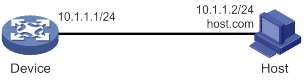
Configuration procedure
# Configure a mapping between the host name host.com and the IP address 10.1.1.2.
<Sysname> system-view
[Sysname] ip host host.com 10.1.1.2
# Verify that the device can use static domain name resolution to resolve the domain name host.com into the IP address 10.1.1.2.
[Sysname] ping host.com
Ping host.com (10.1.1.2): 56 data bytes, press CTRL_C to break
56 bytes from 10.1.1.2: icmp_seq=0 ttl=255 time=1.000 ms
56 bytes from 10.1.1.2: icmp_seq=1 ttl=255 time=1.000 ms
56 bytes from 10.1.1.2: icmp_seq=2 ttl=255 time=1.000 ms
56 bytes from 10.1.1.2: icmp_seq=3 ttl=255 time=1.000 ms
56 bytes from 10.1.1.2: icmp_seq=4 ttl=255 time=2.000 ms
--- Ping statistics for host.com ---
5 packet(s) transmitted, 5 packet(s) received, 0.0% packet loss
round-trip min/avg/max/std-dev = 1.000/1.200/2.000/0.400 ms
Dynamic domain name resolution configuration example
Network requirements
As shown in Figure 43, configure the DNS server to store the mapping between the host's domain name host and IPv4 address 3.1.1.1/16 in the com domain. Configure dynamic IPv4 DNS and the DNS suffix com on the device so that the device can use the domain name host to access the host.
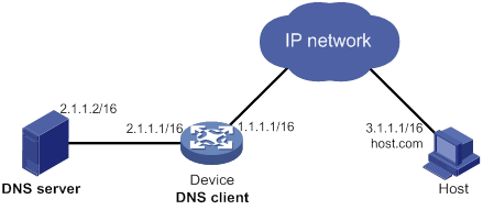
Configuration procedure
Before performing the following configuration, make sure that:
· The device and the host can reach each other.
· The IP addresses of the interfaces are configured as shown in Figure 43.
1. Configure the DNS server:
The configuration might vary by DNS server. The following configuration is performed on a PC running Windows Server 2008 R2.
a. Select Start > Programs > Administrative Tools > DNS.
The DNS server configuration page appears, as shown in Figure 44.
b. Right-click Forward Lookup Zones, select New Zone, and then follow the wizard to create a new zone named com.
Figure 44 Creating a zone

c. On the DNS server configuration page, right-click zone com and select New Host.

d. On the page that appears, enter the host name host and the IP address 3.1.1.1.
e. Click Add Host.
The mapping between the IP address and host name is created.
Figure 46 Adding a mapping between domain name and IP address
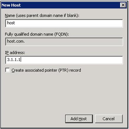
2. Configure the DNS client:
# Specify the DNS server 2.1.1.2.
<Sysname> system-view
[Sysname] dns server 2.1.1.2
# Specify com as the name suffix.
[Sysname] dns domain com
Verifying the configuration
# Verify that the device can use the dynamic domain name resolution to resolve the domain name host.com into the IP address 3.1.1.1.
[Sysname] ping host
Ping host.com (3.1.1.1): 56 data bytes, press CTRL_C to break
56 bytes from 3.1.1.1: icmp_seq=0 ttl=255 time=1.000 ms
56 bytes from 3.1.1.1: icmp_seq=1 ttl=255 time=1.000 ms
56 bytes from 3.1.1.1: icmp_seq=2 ttl=255 time=1.000 ms
56 bytes from 3.1.1.1: icmp_seq=3 ttl=255 time=1.000 ms
56 bytes from 3.1.1.1: icmp_seq=4 ttl=255 time=2.000 ms
--- Ping statistics for host ---
5 packet(s) transmitted, 5 packet(s) received, 0.0% packet loss
round-trip min/avg/max/std-dev = 1.000/1.200/2.000/0.400 ms
DNS proxy configuration example
Network requirements
As shown in Figure 47, configure Device A as the DNS proxy to forward DNS packets between the DNS client (Device B) and the DNS server at 4.1.1.1.

Configuration procedure
Before performing the following configuration, make sure that:
· Device A, the DNS server, and the host can reach each other.
· The IP addresses of the interfaces are configured as shown in Figure 47.
1. Configure the DNS server:
The configuration might vary by DNS server. When a PC running Windows Server 2008 R2 acts as the DNS server, see "Dynamic domain name resolution configuration example" for configuration information.
2. Configure the DNS proxy:
# Specify the DNS server 4.1.1.1.
<DeviceA> system-view
[DeviceA] dns server 4.1.1.1
# Enable DNS proxy.
[DeviceA] dns proxy enable
3. Configure the DNS client:
<DeviceB> system-view
# Specify the DNS server 2.1.1.2.
[DeviceB] dns server 2.1.1.2
Verifying the configuration
# Verify that DNS proxy on Device A functions.
[DeviceB] ping host.com
Ping host.com (3.1.1.1): 56 data bytes, press CTRL_C to break
56 bytes from 3.1.1.1: icmp_seq=0 ttl=255 time=1.000 ms
56 bytes from 3.1.1.1: icmp_seq=1 ttl=255 time=1.000 ms
56 bytes from 3.1.1.1: icmp_seq=2 ttl=255 time=1.000 ms
56 bytes from 3.1.1.1: icmp_seq=3 ttl=255 time=1.000 ms
56 bytes from 3.1.1.1: icmp_seq=4 ttl=255 time=2.000 ms
--- Ping statistics for host.com ---
5 packet(s) transmitted, 5 packet(s) received, 0.0% packet loss
round-trip min/avg/max/std-dev = 1.000/1.200/2.000/0.400 ms
IPv6 DNS configuration examples
Static domain name resolution configuration example
Network requirements
As shown in Figure 48, the host at 1::2 is named host.com. Configure static IPv6 DNS on the device so that the device can use the easy-to-remember domain name rather than the IPv6 address to access the host.
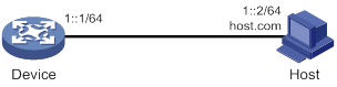
Configuration procedure
# Configure a mapping between the host name host.com and the IPv6 address 1::2.
<Device> system-view
[Device] ipv6 host host.com 1::2
# Verify that the device can use static domain name resolution to resolve the domain name host.com into the IPv6 address 1::2.
[Sysname] ping ipv6 host.com
Ping6(56 data bytes) 1::1 --> 1::2, press CTRL_C to break
56 bytes from 1::2, icmp_seq=0 hlim=128 time=1.000 ms
56 bytes from 1::2, icmp_seq=1 hlim=128 time=0.000 ms
56 bytes from 1::2, icmp_seq=2 hlim=128 time=1.000 ms
56 bytes from 1::2, icmp_seq=3 hlim=128 time=1.000 ms
56 bytes from 1::2, icmp_seq=4 hlim=128 time=0.000 ms
--- Ping6 statistics for host.com ---
5 packet(s) transmitted, 5 packet(s) received, 0.0% packet loss
round-trip min/avg/max/std-dev = 0.000/0.600/1.000/0.490 ms
Dynamic domain name resolution configuration example
Network requirements
As shown in Figure 49, configure the DNS server to store the mapping between the host's domain name host and IPv6 address 1::1/64 in the com domain. Configure dynamic IPv6 DNS and the DNS suffix com on the device so that the device can use the domain name host to access the host.
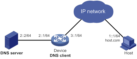
Configuration procedure
Before performing the following configuration, make sure that:
· The device and the host can reach each other.
· The IPv6 addresses of the interfaces are configured as shown in Figure 49.
1. Configure the DNS server:
The configuration might vary by DNS server. The following configuration is performed on a PC running Windows Server 2008 R2. Make sure that the DNS server supports IPv6 DNS so that the server can process IPv6 DNS packets and its interfaces can forward IPv6 packets.
a. Select Start > Programs > Administrative Tools > DNS.
The DNS server configuration page appears, as shown in Figure 50.
b. Right-click Forward Lookup Zones, select New Zone, and then follow the wizard to create a new zone named com.
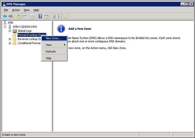
c. On the DNS server configuration page, right-click zone com and select New Host.
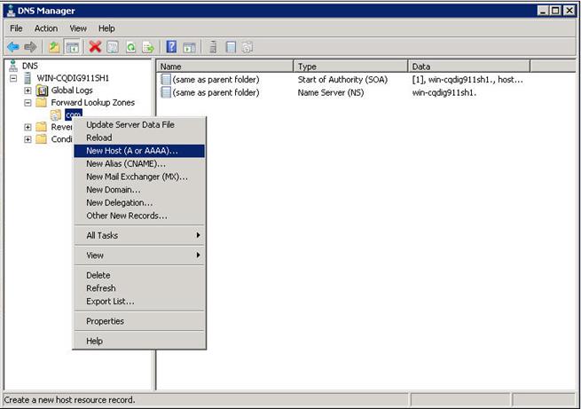
d. On the page that appears, enter the host name host and the IPv6 address 1::1.
e. Click Add Host.
The mapping between the IPv6 address and host name is created.
Figure 52 Adding a mapping between domain name and IPv6 address
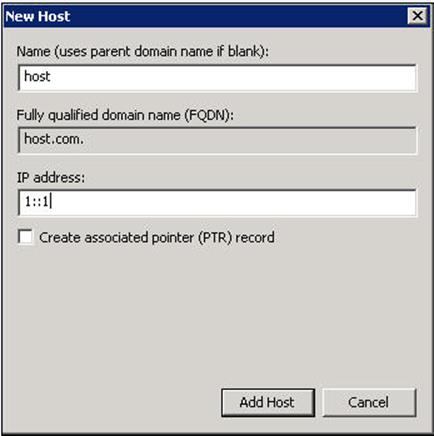
2. Configure the DNS client:
# Specify the DNS server 2::2.
<Device> system-view
[Device] ipv6 dns server 2::2
# Configure com as the DNS suffix.
[Device] dns domain com
Verifying the configuration
# Verify that the device can use the dynamic domain name resolution to resolve the domain name host.com into the IP address 1::1.
[Device] ping ipv6 host
Ping6(56 data bytes) 3::1 --> 1::1, press CTRL_C to break
56 bytes from 1::1, icmp_seq=0 hlim=128 time=1.000 ms
56 bytes from 1::1, icmp_seq=1 hlim=128 time=0.000 ms
56 bytes from 1::1, icmp_seq=2 hlim=128 time=1.000 ms
56 bytes from 1::1, icmp_seq=3 hlim=128 time=1.000 ms
56 bytes from 1::1, icmp_seq=4 hlim=128 time=0.000 ms
--- Ping6 statistics for host ---
5 packet(s) transmitted, 5 packet(s) received, 0.0% packet loss
round-trip min/avg/max/std-dev = 0.000/0.600/1.000/0.490 ms
DNS proxy configuration example
Network requirements
As shown in Figure 53, configure Device A as the DNS proxy to forward DNS packets between the DNS client (Device B) and the DNS server at 4000::1.
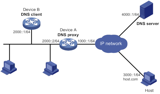
Configuration procedure
Before performing the following configuration, make sure that:
· Device A, the DNS server, and the host are reachable to each other.
· The IPv6 addresses of the interfaces are configured as shown in Figure 53.
1. Configure the DNS server:
This configuration might vary by DNS server. When a PC running Windows Server 2008 R2 acts as the DNS server, see "Dynamic domain name resolution configuration example" for configuration information.
2. Configure the DNS proxy:
# Specify the DNS server 4000::1.
<DeviceA> system-view
[DeviceA] ipv6 dns server 4000::1
# Enable DNS proxy.
[DeviceA] dns proxy enable
3. Configure the DNS client:
# Specify the DNS server 2000::2.
<DeviceB> system-view
[DeviceB] ipv6 dns server 2000::2
Verifying the configuration
# Verify that DNS proxy on Device A functions.
[DeviceB] ping host.com
Ping6(56 data bytes) 2000::1 --> 3000::1, press CTRL_C to break
56 bytes from 3000::1, icmp_seq=0 hlim=128 time=1.000 ms
56 bytes from 3000::1, icmp_seq=1 hlim=128 time=0.000 ms
56 bytes from 3000::1, icmp_seq=2 hlim=128 time=1.000 ms
56 bytes from 3000::1, icmp_seq=3 hlim=128 time=1.000 ms
56 bytes from 3000::1, icmp_seq=4 hlim=128 time=0.000 ms
--- Ping6 statistics for host.com ---
5 packet(s) transmitted, 5 packet(s) received, 0.0% packet loss
round-trip min/avg/max/std-dev = 0.000/0.600/1.000/0.490 ms
Troubleshooting IPv4 DNS configuration
Failure to resolve IPv4 addresses
Symptom
After enabling dynamic domain name resolution, the user cannot get the correct IP address.
Solution
To resolve the problem:
1. Use the display dns host ip command to verify that the specified domain name is in the cache.
2. If the specified domain name does not exist, check that the DNS client can communicate with the DNS server.
3. If the specified domain name is in the cache, but the IP address is incorrect, check that the DNS client has the correct IP address of the DNS server.
4. Verify that the mapping between the domain name and IP address is correct on the DNS server.
Troubleshooting IPv6 DNS configuration
Failure to resolve IPv6 addresses
Symptom
After enabling dynamic domain name resolution, the user cannot get the correct IPv6 address.
Solution
To resolve the problem:
1. Use the display dns host ipv6 command to verify that the specified domain name is in the cache.
2. If the specified domain name does not exist, check that dynamic domain name resolution is enabled, and that the DNS client can communicate with the DNS server.
3. If the specified domain name is in the cache, but the IPv6 address is incorrect, check that the DNS client has the correct IPv6 address of the DNS server.
4. Verify that the mapping between the domain name and IPv6 address is correct on the DNS server.
Configuring DDNS
Overview
DNS provides only the static mappings between domain names and IP addresses. When the IP address of a node changes, your access to the node fails.
Dynamic Domain Name System (DDNS) can dynamically update the mappings between domain names and IP addresses for DNS servers.
DDNS is supported only by IPv4 DNS, and it is used to update the mappings between domain names and IPv4 addresses.
DDNS application
As shown in Figure 54, DDNS works on the client-server model.
· DDNS client—A device that needs to update the mapping between its domain name and IP address dynamically on the DNS server when its IP address changes. An Internet user typically accesses an application layer server such as an HTTP server or an FTP server by using the server's domain name. When its IP address changes, the application layer server runs as a DDNS client. It sends a request to the DDNS server for updating the mapping between its domain name and its IP address.
· DDNS server—Informs the DNS server of latest mappings. When receiving the mapping update request from a DDNS client, the DDNS server tells the DNS server to re-map the domain name and the IP address of the DDNS client. Therefore, the Internet users can use the same domain name to access the DDNS client even if the IP address of the DDNS client has changed.
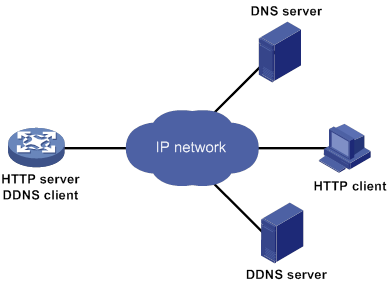
With the DDNS client configured, a device can dynamically update the latest mapping between its domain name and IP address on the DNS server through DDNS servers.
|
|
NOTE: The DDNS update process does not have a unified standard but varies by DDNS server that the DDNS client contacts. |
Feature and hardware compatibility
|
Hardware |
DDNS compatibility |
|
MSR810/810-W/810-W-DB/810-LM/810-W-LM/810-10-PoE /810-LM-HK/MSR810-W-LM-HK |
Yes |
|
MSR810-LMS/810-LUS |
No |
|
MSR2600-6-X1/2600-10-X1 |
Yes |
|
MSR 2630 |
Yes |
|
MSR3600-28/3600-51 |
Yes |
|
MSR3600-28-SI/3600-51-SI |
No |
|
MSR3610-X1/3610-X1-DP/3610-X1-DC/3610-X1-DP-DC |
Yes |
|
MSR 3610/3620/3620-DP/3640/3660 |
Yes |
|
MSR 5620/5660/5680 |
Yes |
|
Hardware |
DDNS compatibility |
|
MSR810-LM-GL |
Yes |
|
MSR810-W-LM-GL |
Yes |
|
MSR830-6EI-GL |
Yes |
|
MSR830-10EI-GL |
Yes |
|
MSR830-6HI-GL |
Yes |
|
MSR830-10HI-GL |
Yes |
|
MSR2600-6-X1-GL |
Yes |
|
MSR3600-28-SI-GL |
No |
DDNS client configuration task list
|
Tasks at a glance |
|
(Required.) Configuring a DDNS policy |
|
(Required.) Applying the DDNS policy to an interface |
|
(Optional.) Setting the DSCP value for outgoing DDNS packets |
Configuring a DDNS policy
A DDNS policy contains the DDNS server address, port number, login ID, password, time interval, associated SSL client policy, and update time interval. After creating a DDNS policy, you can apply it to multiple interfaces to simplify DDNS configuration.
The URL addresses configured for update requests vary by DDNS server.
Table 6 Common URL addresses
|
DDNS server |
URL addresses for DDNS update requests |
|
www.3322.org |
http://members.3322.org/dyndns/update?system=dyndns&hostname=<h>&myip=<a> |
|
DYNDNS |
http://members.dyndns.org/nic/update?system=dyndns&hostname=<h>&myip=<a> |
|
DYNS |
http://www.dyns.cx/postscript.php?host=<h>&ip=<a> |
|
ZONEEDIT |
http://dynamic.zoneedit.com/auth/dynamic.html?host=<h>&dnsto=<a> |
|
TZO |
http://cgi.tzo.com/webclient/signedon.html?TZOName=<h>IPAddress=<a> |
|
EASYDNS |
http://members.easydns.com/dyn/ez-ipupdate.php?action=edit&myip=<a>&host_id=<h> |
|
HEIPV6TB |
http://dyn.dns.he.net/nic/update?hostname=<h>&myip=<a> |
|
CHANGE-IP |
http://nic.changeip.com/nic/update?hostname=<h>&offline=1 |
|
NO-IP |
http://dynupdate.no-ip.com/nic/update?hostname=<h>&myip=<a> |
|
DHS |
http://members.dhs.org/nic/hosts?domain=dyn.dhs.org&hostname=<h>&hostscmd=edit&hostscmdstage=2&type=1&ip=<a> |
|
HP |
https://server-name/nic/update?group=group-name&myip=<a> |
|
ODS |
ods://update.ods.org |
|
GNUDIP |
gnudip://server-name |
|
PeanutHull |
oray://phservice2.oray.net |
The URL address cannot contain the username or password. To configure the username and password, use the username command and the password command.
HP and GNUDIP are common DDNS update protocols. The server-name parameter is the domain name or IP address of the service provider's server using one of the update protocols.
The URL address for an update request can start with:
· http://—The HTTP-based DDNS server.
· https://—The HTTPS-based DDNS server.
· ods://—The TCP-based ODS server.
· gnudip://—The TCP-based GNUDIP server.
· oray://—The TCP-based DDNS server.
The domain names of DDNS servers are members.3322.org and phservice2.oray.net. The domain names of PeanutHull DDNS servers can be phservice2.oray.net, phddns60.oray.net, client.oray.net, ph031.oray.net, and so on. Determine the domain name in the URL according to the actual situation.
The port number in the URL address is optional. If no port is specified, the system uses the default port numbers: port 80 for HTTP, port 443 for HTTPS, and port 6060 for PeanutHull DDNS server.
The system automatically performs the following tasks:
· Fills <h> with the FQDN that is specified when the DDNS policy is applied to an interface.
· Fills <a> with the primary IP address of the interface to which the DDNS policy is applied.
You can also manually specify an FQDN and an IP address in <h> and <a>. In this case, the FQDN that is specified when the DDNS policy is applied to an interface will not take effect. As a best practice, do not manually change the <h> and <a> because your configuration might be incorrect. For more information about applying DDNS policies, see "Applying the DDNS policy to an interface."
No FQDN or IP address can be specified in the URL address for update requests sent to the PeanutHull DDNS server. You can specify the FQDN when applying the DDNS policy to an interface. The IP address is the primary IP address of the interface to which the DDNS policy is applied.
|
|
TIP: The FQDN is the only identification of a node in the network. An FQDN consists of a local host name and a parent domain name and can be translated into an IP address. |
Configuration prerequisites
Visit the website of a DDNS service provider, register an account, and apply for a domain name for the DDNS client. When the DDNS client updates the mapping between the domain name and the IP address through the DDNS server, the DDNS server checks the following:
· Whether the account information is correct.
· Whether the domain name to be updated belongs to the account.
Configuration procedure
To configure a DDNS policy:
|
Step |
Command |
Remarks |
|
1. Enter system view. |
system-view |
N/A |
|
2. Create a DDNS policy and enter its view. |
ddns policy policy-name |
By default, no DDNS policy is created. |
|
3. Specify a URL address for DDNS update requests. |
url request-url |
By default, no URL address is specified for DDNS update requests. |
|
4. Specify the username for logging in to the DDNS server. |
username username |
By default, no username is specified. |
|
5. Specify the password for logging in to the DDNS server. |
password { cipher | simple } string |
By default, no password is specified. |
|
6. (Optional.) Specify the parameter transmission method for sending DDNS update requests to HTTP/HTTPS-based DDNS servers. |
method { http-get | http-post } |
By default, http-get is used. Use the method http-post command to specify the POST method for DDNS update with a DHS server. |
|
7. (Optional.) Associate an SSL client policy with the DDNS policy. |
ssl-client-policy policy-name |
By default, no SSL client policy is associated with the DDNS policy. This step is only effective and a must for HTTP-based DDNS update requests. For SSL client policy configuration, see Security Configuration Guide. |
|
8. (Optional.) Specify the interval for sending update requests. |
interval days [ hours [ minutes ] ] |
By default, the time interval is one hour. |
Applying the DDNS policy to an interface
After you apply the DDNS policy to an interface and specify the FQDN for update, the DDNS client sends requests to the DDNS server to update the mapping between the domain name and the primary IP address of the interface at the specified interval.
Before you apply a DDNS policy to an interface, complete the following tasks:
· Specify the primary IP address of the interface and make sure the DDNS server and the interface can reach each other.
· Configure static or dynamic domain name resolution to translate the domain name of the DDNS server into the IPv4 address. For more information, see "Configuring the IPv4 DNS client."
To apply the DDNS policy to an interface:
|
Step |
Command |
Remarks |
|
1. Enter system view. |
system-view |
N/A |
|
2. Enter interface view. |
interface interface-type interface-number |
N/A |
|
3. Apply the DDNS policy to the interface to update the mapping between the specified FQDN and the primary IP address of the interface, and enable DDNS update. |
ddns apply policy policy-name [ fqdn domain-name ] |
By default, no DDNS policy is applied to the interface, no FQDN is specified for update, and DDNS update is disabled. The fqdn domain-name option must be specified for all DDNS servers except the PeanutHull DDNS server. |
|
|
NOTE: If no FQDN is specified for the PeanutHull DDNS server, the DDNS server updates all domain names of the DDNS client account. If an FQDN is specified, the DDNS server updates only the mapping between the specified FQDN and the primary IP address. |
Setting the DSCP value for outgoing DDNS packets
The DSCP value of a packet specifies the priority level of the packet and affects the transmission priority of the packet. A bigger DSCP value represents a higher priority.
To set the DSCP value for outgoing DDNS packets:
|
Step |
Command |
Remarks |
|
1. Enter system view. |
system-view |
N/A |
|
2. Set the DSCP value for outgoing DDNS packets. |
ddns dscp dscp-value |
By default, the DSCP value for outgoing DDNS packets is 0. |
Displaying DDNS
Execute display commands in any view.
|
Task |
Command |
|
Display DDNS policy information. |
display ddns policy [ policy-name ] |
DDNS configuration examples
DDNS configuration example with www.3322.org
Network requirements
As shown in Figure 55, the router is a Web server with the domain name whatever.3322.org and uses an IP address dynamically obtained through DHCP. To make sure the router can always provide Web services at whatever.3322.org when its IP address changes, perform the following tasks on the router:
· Configure a DDNS policy to update the router's domain name-to-IP address mapping on the DDNS server. The DDNS server then updates the mapping on the DNS server.
· Specify the IP address of the DNS server so that the router can access the DDNS server through domain name.

Configuration procedure
Before configuring DDNS on Router, perform the following tasks:
· Register with username steven and password nevets at http://www.3322.org/.
· Configure a DDNS policy to update the mapping between the router's FQDN and IP address.
· Make sure the devices can reach each other.
# Create a DDNS policy named 3322.org, and enter its view.
<Router> system-view
[Router] ddns policy 3322.org
# Specify the URL address, username, and password for DDNS update requests.
[Router-ddns-policy-3322.org] url http://members.3322.org/dyndns/update?system=dyndns&hostname=<h>&myip=<a>
[Router-ddns-policy-3322.org] username steven
[Router-ddns-policy-3322.org] password simple nevets
# Set the interval to 15 minutes for sending DDNS update requests.
[Router-ddns-policy-3322.org] interval 0 0 15
[Router-ddns-policy-3322.org] quit
# Specify the IP address of the DNS server as 1.1.1.1.
[Router] dns server 1.1.1.1
# Apply DDNS policy 3322.org to GigabitEthernet 1/0/1 to enable DDNS update. The mapping between domain name whatever.3322.org and the primary IP address of GigabitEthernet 1/0/1 will be dynamically updated.
[Router] interface gigabitethernet 1/0/1
[Router-GigabitEthernet1/0/1] ddns apply policy 3322.org fqdn whatever.3322.org
DDNS configuration example with PeanutHull server
Network requirements
As shown in Figure 56, the router is a Web server with domain name whatever.gicp.cn and uses an IP address dynamically obtained through DHCP. To make sure the router can always provide Web services at whatever.gicp.cn when its IP address changes, perform the following tasks on the router:
· Configure a DDNS policy to update the router's domain name-to-IP address mapping on the DDNS server. The DDNS server then updates the mapping on the DNS server.
· Specify the IP address of the DNS server so that the router can access the DDNS server through domain name.
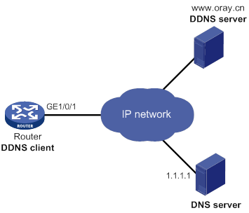
Configuration procedure
Before configuring DDNS on Router, perform the following tasks:
· Register with username steven and password nevets at http://www.oray.cn/.
· Configure a DDNS policy to update the mapping between the router's FQDN and IP address.
· Make sure the devices can reach each other.
# Create a DDNS policy named oray.cn and enter its view.
<Router> system-view
[Router] ddns policy oray.cn
# Specify the URL address, username, and password for DDNS update requests.
[Router-ddns-policy-oray.cn] url oray://phservice2.oray.net
[Router-ddns-policy-oray.cn] username steven
[Router-ddns-policy-oray.cn] password simple nevets
# Set the DDNS update request interval to 12 minutes.
[Router-ddns-policy-oray.cn] interval 0 0 12
[Router-ddns-policy-oray.cn] quit
# Specify the IP address of the DNS server as 1.1.1.1.
[Router] dns server 1.1.1.1
# Apply the DDNS policy to GigabitEthernet 1/0/1 to enable DDNS update. The mapping between whatever.gicp.cn and the primary IP address of GigabitEthernet 1/0/1 will be dynamically updated.
[Router] interface gigabitethernet 1/0/1
[Router-GigabitEthernet1/0/1] ddns apply policy oray.cn fqdn whatever.gicp.cn
Configuring NAT
Overview
Network Address Translation (NAT) translates an IP address in the IP packet header to another IP address. Typically, NAT is configured on gateways to enable private hosts to access external networks and external hosts to access private network resources such as a Web server.
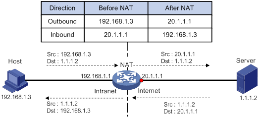
As shown in Figure 57:
1. Upon receiving a request from the host to the server, NAT translates the private source address 192.168.1.3 to the public address 20.1.1.1 and forwards the NATed packet. NAT adds a mapping for the two addresses to its NAT table.
2. Upon receiving a response from the server, NAT translates the destination public address to the private address, and forwards the packet to the host.
The NAT operation is transparent to the terminals. NAT hides the private network from the external users and shows that the IP address of the internal host is 20.1.1.1.
Terminology
The following describes NAT terminologies:
· NAT device—A device configured with NAT.
· NAT interface—An interface enabled with NAT.
· NAT rule—Rules that define how to perform address translation.
· NAT entry—Stores the mapping between a private address and a public address. For more information, see "NAT entries."
· Easy IP—Uses the IP address of an interface as the public address. The IP address of the interface is obtained through DHCP or PPPoE.
NAT types
Traditional NAT
Traditional NAT applies to the interface connected to the public network. It translates the source IP addresses of outgoing packets and destination IP addresses of incoming packets.
Bidirectional NAT
NAT translates the source and destination IP addresses of incoming packets on the receiving interface and outgoing packets on the sending interface.
Bidirectional NAT is applied when source and destination addresses overlap.
Twice NAT
Twice NAT translates the destination IP address on the receiving interface, and the source IP address on the sending interface. The receiving and sending interfaces are both NAT interfaces.
Twice NAT allows VPNs with overlapping addresses to access each other.
NAT hairpin
NAT hairpin allows internal hosts to access each other through NAT. The source and destination IP address of the packets are translated on the interface connected to the internal network.
NAT hairpin includes P2P and C/S modes:
· P2P—Allows internal hosts to access each other through NAT.
· C/S—Allows internal hosts to access internal servers through NAT.
NAT control
You can use ACLs to implement NAT control. The match criteria in the ACLs include the source IP address, source port number, destination IP address, destination port number, transport layer protocol, and VPN instance. Only packets permitted by an ACL are processed by NAT.
Command and hardware compatibility
Commands and descriptions for centralized devices apply to the following routers:
· MSR810/810-W/810-W-DB/810-LM/810-W-LM/810-10-PoE/810-LM-HK/810-W-LM-HK/810-LMS/810-LUS.
· MSR2600-6-X1/2600-10-X1.
· MSR 2630.
· MSR3600-28/3600-51.
· MSR3600-28-SI/3600-51-SI.
· MSR3610-X1/3610-X1-DP/3610-X1-DC/3610-X1-DP-DC.
· MSR 3610/3620/3620-DP/3640/3660.
· MSR810-LM-GL/810-W-LM-GL/830-6EI-GL/830-10EI-GL/830-6HI-GL/830-10HI-GL/2600-6-X1-GL/3600-28-SI-GL.
Commands and descriptions for distributed devices apply to the following routers:
· MSR5620.
· MSR 5660.
· MSR 5680.
NAT implementations
Static NAT
Static NAT creates a fixed mapping between a private address and a public address. Static NAT allows bidirectional connection initiation, both from and to the internal host. Static NAT applies to regular communications.
Dynamic NAT
Dynamic NAT uses an address pool to translate addresses. Dynamic NAT includes Not Port Address Translation (NO-PAT) and Port Address Translation (PAT) modes.
NO-PAT
NO-PAT translates a private address to a public address. The public address cannot be used by another internal host until it is released.
NO-PAT supports all IP packets.
PAT
PAT translates multiple private addresses to a single public address by mapping the private address and source port to the public address and a unique port. PAT supports TCP and UDP packets, and ICMP request packets.
Figure 58 PAT operation
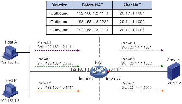
As shown in Figure 58, PAT translates the source IP addresses of the three packets to the same public address and translates their port numbers to different port numbers. Upon receiving a response, PAT translates the destination address and port number of the response, and forwards it to the target host.
PAT supports the following mappings:
· Endpoint-Independent Mapping (EIM)—Uses the same IP and port mapping (EIM entry) for packets from the same source IP and port to any destinations. EIM allows external hosts to initiate connections to the translated IP addresses and ports of internal hosts. It allows internal hosts behind different NAT gateways to access each other.
· Address and Port-Dependent Mapping (APDM)—Uses different IP and port mappings for packets from the same source IP and port to different destination IP addresses and ports. APDM allows an external host to initiate connections to an internal host only under the condition that the internal host has previously accessed the external host. It is secure, but it does not allow internal hosts behind different NAT gateways to access each other.
NAT Server
The NAT Server feature maps a public address and port number to the private IP address and port number of an internal server. This feature allows servers in the private network to provide services for external users.
Figure 59 NAT Server operation
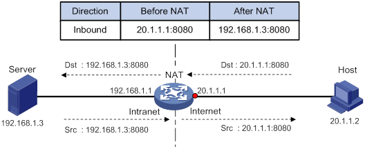
Figure 59 displays how NAT Server works:
1. Upon receiving a request from the host, NAT translates the public destination IP address and port number to the private IP address and port number of the internal server.
2. Upon receiving a response from the server, NAT translates the private source IP address and port number to the public IP address and port number.
NAT444
NAT444 provides carrier-grade NAT. It is a preferred solution for carriers to mitigate IPv4 address exhaustion. It introduces a second layer of NAT on the carrier side, with few changes on the customer side and the application server side.
NAT444 provides port block-based PAT translation. It maps multiple private IP addresses to one public IP address and uses a different port block for each private IP address. For example, the private IP address 10.1.1.1 of an internal host is mapped to the public IP address 202.1.1.1 and port block 10001 to 10256. When the internal host accesses public hosts, the source IP address 10.1.1.1 is translated to 202.1.1.1, and the source ports are translated to ports in the port block 10001 to 10256.
NAT444 includes static NAT444 and dynamic NAT444.
As shown in Figure 60, the NAT444 architecture includes the following entities:
· CPE—Provides NAT services on the customer side.
· BRAS—Provides Internet access services.
· NAT444 gateway—Provides carrier-grade NAT services.
· AAA server—Cooperates with BRAS to provide user authentication, authorization, and accounting services.
· Log server—Records user access logs and responds to queries for user access information.
The AAA server authenticates the internal users and starts accounting after users pass the authentication. The BRAS device assigns private IP addresses to authenticated users. When a user accesses the external network, the NAT444 gateway assigns the user a public IP address and port block, and sends the mapping to the log server. The next time the user accesses the external network, the NAT444 gateway assigns a new mapping if the former mapping ages out and sends the new mapping to the log server. The log server uses the mappings for user tracing.
Figure 60 NAT444 application diagram
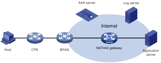
Static NAT444
The NAT444 gateway computes a static NAT444 mapping before address translation. The mapping is between a private IP address and a public IP address with a port block.
The NAT444 gateway uses private IP addresses, public IP addresses, a port range, and a port block size to compute static mappings:
1. Divides the port range by the port block size to get the number of available port blocks for each public IP address.
This value is the base number for mapping.
2. Sorts the port blocks in ascending order of the start port number in each block.
3. Sorts the private IP addresses and the public IP addresses separately in ascending order.
4. Maps the first base number of private IP addresses to the first public IP address and its port blocks in ascending order.
For example, the number of available port blocks of each public IP address is m. The first m private IP addresses are mapped to the first public IP address and the m port blocks in ascending order. The next m private IP addresses are mapped to the second IP address and the m port blocks in ascending order. The other static NAT444 mappings are created by analogy.
Dynamic NAT444
Dynamic NAT444 works as follows:
1. Creates a mapping from the internal host's private IP address to a public IP address and a port block when the host initiates a connection to the public network.
2. Translates the private IP address to the public IP address, and the source ports to ports in the selected port block for subsequent connections from the private IP address.
3. Withdraws the port block and deletes the dynamic NAT444 mapping when all connections from the private IP address are disconnected.
Dynamic NAT444 uses ACLs to implement translation control. It processes only packets that match an ACL permit rule.
Dynamic NAT444 supports port block extending. If the ports in the port block for a private address are all occupied, dynamic NAT444 translates the source port to a port in an extended port block.
NAT444 gateway unified with BRAS device
The following matrix shows the feature and hardware compatibility:
|
Hardware |
NAT444 gateway and BRAS device unification compatibility |
|
MSR810/810-W/810-W-DB/810-LM/810-W-LM/810-10-PoE/810-LM-HK/810-W-LM-HK/810-LMS/810-LUS |
No |
|
MSR2600-6-X1/2600-10-X1 |
No |
|
MSR 2630 |
Yes |
|
MSR3600-28/3600-51 |
Yes |
|
MSR3600-28-SI/3600-51-SI |
No |
|
MSR3610-X1/3610-X1-DP/3610-X1-DC/3610-X1-DP-DC |
Yes |
|
MSR 3610/3620/3620-DP/3640/3660 |
Yes |
|
MSR5620/5660/5680 |
Yes |
|
Hardware |
NAT444 gateway and BRAS device unification compatibility |
|
MSR810-LM-GL |
No |
|
MSR810-W-LM-GL |
No |
|
MSR830-6EI-GL |
No |
|
MSR830-10EI-GL |
No |
|
MSR830-6HI-GL |
No |
|
MSR830-10HI-GL |
No |
|
MSR2600-6-X1-GL |
No |
|
MSR3600-28-SI-GL |
No |
NAT444 gateway and BRAS device unification is supported only for PPP users.
To unify the NAT444 gateway and BRAS device, specify the user address type in the ISP domain. Supported user address types include private IPv4 address, private-DS address, and DS-Lite address.
As shown in Figure 61, the NAT444 gateway and BRAS device function as follows after the unification:
1. After a user of the specified address type passes authentication and obtains a private address, NAT444 immediately assigns a public IP address and a port block to the user.
2. NAT444 sends the NAT444 mapping to the BRAS.
3. The BRAS records the mapping and reports it to the AAA server.
Compared to the separation of BRAS and NAT444, the unification provides the following functions:
· If the NAT444 resources have been used up, the BRAS logs off the user, which ensures accurate accounting on the AAA server.
· The AAA server maintains one mapping for each online user until the user goes offline. This solution implements user tracing without requiring an extra log server.
Figure 61 NAT444 gateway unified with BRAS device
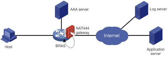
|
|
NOTE: If the NAT444 configuration changes, NAT444 mappings for online users also change. The change cannot be synchronized to the AAA server, affecting user tracing accuracy. As a best practice, log off the users immediately after you change the NAT444 configuration. When the users come online, NAT444 creates new mappings for them. |
DS-Lite NAT444
DS-Lite combines tunneling and NAT to allow an IPv4 private network to access the IPv4 public network over an IPv6 network. For more information about DS-Lite, see "Configuring tunneling."
DS-Lite NAT444 is configured on the AFTR and performs dynamic NAT444 based on the B4 element. The B4 element refers to a B4 router or a DS-Lite host. DS-Lite NAT444 dynamically maps a public IPv4 address and a port block to the IPv6 address of the B4 element. The DS-Lite host or hosts behind the B4 router use the mapped public IPv4 address and port block to access the public IPv4 network.
DS-Lite NAT444 supports user tracing for DS-Lite hosts based on the port block.
Figure 62 DS-Lite NAT444
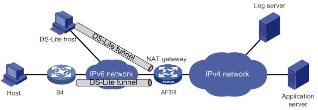
NAT entries
NAT session entry
NAT creates a NAT session entry for a session and creates an address mapping for the first packet in the session.
A NAT session entry contains extended NAT information, such as interface and translation method. Subsequent packets of the session are translated by using this entry.
The session management module maintains the updating and aging of NAT session entries. For information about session management, see Security Configuration Guide.
EIM entry
An EIM entry maps a private address/port to a public address/port. The same EIM entry applies to subsequent connections originating from the same source IP and port.
An EIM entry ages out after all related NAT session entries age out.
NO-PAT entry
A NO-PAT entry maps a private address to a public address. The same mapping applies to subsequent connections originating from the same source IP.
A NO-PAT entry can also be created during the ALG process for NAT. For information about NAT ALG, see "NAT ALG."
A NO-PAT entry ages out after all related NAT session entries age out.
NAT444 entry
A NAT444 entry maps a private IP address to a public IP address and a port block.
NAT444 entries include static and dynamic NAT444 mappings. For information about these mappings, see "Static NAT444" and "Dynamic NAT444."
Using NAT with other features
VRF-aware NAT
VRF-aware NAT allows users from different VRF (VPN instances) to access external networks and to access each other.
1. Upon receiving a request from a user in a VRF to an external network, NAT performs the following tasks:
? Translates the private source IP address and port number to a public IP address and port number.
? Records the VRF information, such as the VRF name.
2. When a response packet arrives, NAT performs the following tasks:
? Translates the destination public IP address and port number to the private IP address and port number.
? Forwards the packet to the target VRF.
NAT DNS mapping
NAT DNS mapping allows an internal host to access an internal server on the same private network by using the domain name of the internal server when the DNS server is on the public network.
NAT DNS mapping must operate with the NAT Server feature.
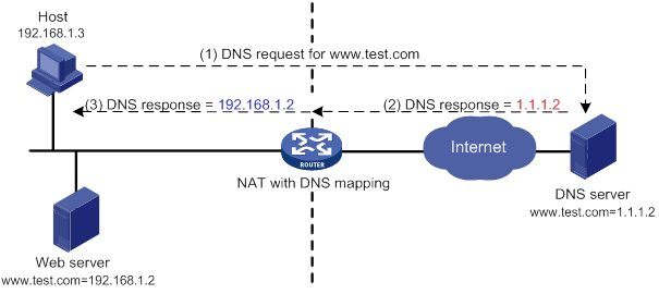
As shown in Figure 63, NAT DNS mapping works as follows:
1. The host sends a DNS request containing the domain name of the internal Web server.
2. Upon receiving the DNS response, the NAT device performs a DNS mapping lookup by using the domain name in the response. A DNS mapping for NAT maps the domain name to the public IP address, public port number, and the protocol type for the internal server.
3. If a match is found, the NAT continues to compare the public address, public port number, and the protocol type with the NAT Server configuration. The NAT Server configuration maps the public IP address and port number to the private IP address and port number for the internal server.
4. If a match is found, NAT translates the public IP address in the response into the private IP address of the Web server.
5. The internal host receives the DNS response, and obtains the private IP address of the Web server.
DNS mapping can also be used by DNS ALG. The DNS reply from the external DNS server contains only the domain name and public IP address of the internal server in the payload. The NAT interface might have multiple internal servers configured with the same public IP address but different private IP addresses. DNS ALG might find an incorrect internal server by using only the public IP address. If a DNS mapping is configured, DNS ALG can obtain the public IP address, public port number, and protocol type of the internal server by using the domain name. Then it can find the correct internal server by using the public IP address, public port number, and protocol type of the internal server.
NAT ALG
NAT ALG translates address or port information in the application layer payloads to ensure connection establishment.
For example, an FTP application includes a data connection and a control connection. The IP address and port number for the data connection depend on the payload information of the control connection. This requires NAT ALG to translate the address and port information for data connection establishment.
NAT configuration task list
|
Tasks at a glance |
Remarks |
|
Perform one or more of the following tasks: |
If you perform all the tasks on an interface, the NAT rules are sorted in the following order: · NAT Server. · Static NAT. · Static NAT444. ·
Dynamic NAT, dynamic NAT444, and DS-Lite
NAT444. |
|
(Optional.) Rearranging NAT rules to adjust their priorities |
N/A |
|
(Optional.) Configuring NAT DNS mapping |
N/A |
|
(Optional.) Configuring NAT hairpin |
N/A |
|
(Optional.) Configuring NAT ALG |
N/A |
|
(Optional.) Configuring NAT logging |
N/A |
|
(Optional.) Enabling sending ICMP error messages for NAT failures |
N/A |
|
(Optional.) Enabling NAT reply redirection |
N/A |
|
(Optional.) Enabling the deletion of timestamps in TCP SYN and SYN ACK packets |
N/A |
NAT configuration restrictions and guidelines
If fast forwarding load sharing is enabled, response packets sent or received on a different interface than request packets are NATed according to fast forwarding entries. If fast forwarding load sharing is disabled, these packets cannot be NATed. For more information about fast forwarding load sharing, see "Configuring fast forwarding."
If NAT is configured on only one output interface in a dual uplink network, do not add the two output interfaces to the same security zone. Doing so will cause traffic interruption. For more information about security zones, see Fundamentals Configuration Guide.
Configuring static NAT
Static NAT includes one-to-one static NAT and net-to-net static NAT for outbound and inbound translation. Do not configure inbound static NAT alone. Typically, inbound static NAT functions with outbound dynamic NAT, NAT Server, or outbound static NAT to implement bidirectional NAT.
Configuration prerequisites
Perform the following tasks before configuring static NAT:
· Configure an ACL to identify the IP addresses to be translated. The match criteria include the source IP address, source port number, destination IP address, destination port number, transport layer protocol, and VPN instance. For more information about ACLs, see ACL and QoS Configuration Guide.
· Manually add a route for inbound static NAT. Use local-ip or local-network as the destination address, and use global-ip, an address in global-network, or the next hop directly connected to the output interface as the next hop.
Configuring outbound one-to-one static NAT
For address translation from a private IP address to a public IP address, configure outbound one-to-one static NAT on the interface connected to the external network.
· When the source IP address of a packet from the private network matches the local-ip, the source IP address is translated into the global-ip.
· When the destination IP address of a packet from the public network matches the global-ip, the destination IP address is translated into the local-ip.
To configure outbound one-to-one static NAT:
|
Step |
Command |
Remarks |
|
1. Enter system view. |
system-view |
N/A |
|
2. Configure a one-to-one mapping for outbound static NAT. |
nat static outbound local-ip [ vpn-instance local-vpn-instance-name ] global-ip [ vpn-instance global-vpn-instance-name ] [ acl { ipv4-acl-number | name ipv4-acl-name } [ reversible ] ] [ rule rule-name ] [ priority priority ] [ disable ] [ counting ] |
By default, no mappings exist. If you specify the acl keyword, NAT processes only packets matching the permit rule in the ACL. |
|
3. Enter interface view. |
interface interface-type interface-number |
N/A |
|
4. Enable static NAT on the interface. |
nat static enable |
By default, static NAT is disabled. |
Configuring outbound net-to-net static NAT
For address translation from a private network to a public network, configure outbound net-to-net static NAT on the interface connected to the external network.
· When the source IP address of a packet from the private network matches the private address range, the source IP address is translated into a public address in the public address range.
· When the destination IP address of a packet from the public network matches the public address range, the destination IP address is translated into a private address in the private address range.
To configure outbound net-to-net static NAT:
|
Step |
Command |
Remarks |
|
1. Enter system view. |
system-view |
N/A |
|
2. Configure a net-to-net mapping for outbound static NAT. |
nat static outbound net-to-net local-start-address local-end-address [ vpn-instance local-vpn-instance-name ] global global-network { mask-length | mask } [ vpn-instance global-vpn-instance-name ] [ acl { ipv4-acl-number | name ipv4-acl-name } [ reversible ] ] [ rule rule-name ] [ priority priority ] [ disable ] [ counting ] |
By default, no mappings exist. If you specify the acl keyword, NAT processes only packets permitted by the ACL. |
|
3. Enter interface view. |
interface interface-type interface-number |
N/A |
|
4. Enable static NAT on the interface. |
nat static enable |
By default, static NAT is disabled. |
Configuring object group-based outbound static NAT
Configure object group-based outbound static NAT on the interface connected to the external network to translate private IP addresses into public IP addresses.
· When the source address of a packet from the private network matches the private address object group, the source address is translated into a public address in the public address object group.
· When the destination address of a packet from the public network matches the public address object group, the destination address is translated into a private address in the private address object group.
An IPv4 address object group used by an object group-based outbound static NAT mapping can only contain a host object or a subnet object. Otherwise, the configuration does not take effect.
To configure object group-based outbound static NAT:
|
Step |
Command |
Remarks |
|
1. Enter system view. |
system-view |
N/A |
|
2. Configure an object group-based outbound static NAT mapping. |
nat static outbound object-group local-object-group-name [ vpn-instance local-vpn-instance-name ] object-group global-object-group-name [ vpn-instance global-vpn-instance-name ] [ acl { ipv4-acl-number | name ipv4-acl-name } [ reversible ] ] [ disable ] [ counting ] |
By default, no mappings exist. If you specify the acl keyword, NAT processes only packets permitted by the ACL. |
|
3. Enter interface view. |
interface interface-type interface-number |
N/A |
|
4. Enable static NAT on the interface. |
nat static enable |
By default, static NAT is disabled. |
Configuring inbound one-to-one static NAT
For address translation from a public IP address to a private IP address, configure inbound one-to-one static NAT.
· When the source IP address of a packet from the public network to the private network matches the global-ip, the source IP address is translated into the local-ip.
· When the destination IP address of a packet from the private network to the public network matches the local-ip, the destination IP address is translated into the global-ip.
To configure inbound one-to-one static NAT:
|
Step |
Command |
Remarks |
|
1. Enter system view. |
system-view |
N/A |
|
2. Configure a one-to-one mapping for inbound static NAT. |
nat static inbound global-ip [ vpn-instance global-vpn-instance-name ] local-ip [ vpn-instance local-vpn-instance-name ] [ acl { ipv4-acl-number | name ipv4-acl-name } [ reversible ] ] [ rule rule-name ] [ priority priority ] [ disable ] [ counting ] |
By default, no mappings exist. If you specify the acl keyword, NAT processes only packets permitted by the ACL. |
|
3. Enter interface view. |
interface interface-type interface-number |
N/A |
|
4. Enable static NAT on the interface. |
nat static enable |
By default, static NAT is disabled. |
Configuring inbound net-to-net static NAT
For address translation from a public network to a private network, configure inbound net-to-net static NAT.
· When the source IP address of a packet from the public network matches the public address range, the source IP address is translated into a private address in the private address range.
· When the destination IP address of a packet from the private network matches the private address range, the destination IP address is translated into a public address in the public address range.
To configure inbound net-to-net static NAT:
|
Step |
Command |
Remarks |
|
1. Enter system view. |
system-view |
N/A |
|
2. Configure a net-to-net mapping for inbound static NAT. |
nat static inbound net-to-net global-start-address global-end-address [ vpn-instance global-vpn-instance-name ] local local-network { mask-length | mask } [ vpn-instance local-vpn-instance-name ] [ acl { ipv4-acl-number | name ipv4-acl-name } [ reversible ] ] [ rule rule-name ] [ priority priority ] [ disable ] [ counting ] |
By default, no mappings exist. If you specify the acl keyword, NAT processes only packets permitted by the ACL. |
|
3. Enter interface view. |
interface interface-type interface-number |
N/A |
|
4. Enable static NAT on the interface. |
nat static enable |
By default, static NAT is disabled. |
Configuring object group-based inbound static NAT
Configure object group-based inbound static NAT to translate public IP addresses into private IP addresses.
· When the source address of a packet from the public network matches the public address object group, the source address is translated into a private address in the private address object group.
· When the destination address of a packet from the private network matches the private address object group, the destination address is translated into a public address in the public address object group.
An IPv4 address object group used by an object group-based inbound static NAT mapping can only contain a host object or a subnet object. Otherwise, the configuration does not take effect.
To configure object group-based inbound static NAT:
|
Step |
Command |
Remarks |
|
1. Enter system view. |
system-view |
N/A |
|
2. Configure an object group-based inbound static NAT mapping. |
nat static inbound object-group global-object-group-name [ vpn-instance global-vpn-instance-name ] object-group local-object-group-name [ vpn-instance local-vpn-instance-name ] [ acl { ipv4-acl-number | name ipv4-acl-name } [ reversible ] ] [ disable ] [ counting ] |
By default, no mappings exist. If you specify the acl keyword, NAT processes only packets permitted by the ACL. |
|
3. Enter interface view. |
interface interface-type interface-number |
N/A |
|
4. Enable static NAT on the interface. |
nat static enable |
By default, static NAT is disabled. |
Configuring dynamic NAT
Dynamic NAT translates a group of private IP addresses into a smaller number of public addresses. You can specify an address group (or the IP address of an interface) and an ACL to implement dynamic NAT.
Configuration restrictions and guidelines
When you configure dynamic NAT, follow these restrictions and guidelines:
· You can configure multiple inbound or outbound dynamic NAT rules.
· A NAT rule with an ACL takes precedence over a rule without any ACL.
· The priority for the ACL-based dynamic NAT rules depends on ACL number. A higher ACL number represents a higher priority.
Configuration prerequisites
Perform the following tasks before configuring dynamic NAT:
· Configure an ACL to identify the IP addresses to be translated. The match criteria include the source IP address, source port number, destination IP address, destination port number, transport layer protocol, and VPN instance. For more information about ACLs, see ACL and QoS Configuration Guide.
· Determine whether to enable the Easy IP feature. If you use the IP address of an interface as the public address, you are configuring Easy IP.
· Determine a public IP address pool for address translation.
· Determine whether to translate port numbers. Use NO-PAT to translate only IP addresses and PAT to translate both IP addresses and port numbers.
Configuring outbound dynamic NAT
To translate private IP addresses into public IP addresses, configure outbound dynamic NAT on the interface connected to the external network.
The source IP addresses of the outgoing packets that match the ACL permit rule are translated into IP addresses in the address group.
The reversible keyword enables the device to perform the following operations:
· Compare the destination IP address in the first packet from the public network with existing NO-PAT entries.
· Translate the destination address into the private address in a matching NO-PAT entry.
To configure outbound dynamic NAT:
|
Step |
Command |
Remarks |
|
1. Enter system view. |
system-view |
N/A |
|
2. Configure an address group and enter its view. |
nat address-group group-id [ name group-name ] |
By default, no address groups exist. |
|
3. Add an address range to the address group. |
address start-address end-address |
By default, no address ranges exist. You can add multiple address ranges to an address group. The address ranges must not overlap. |
|
4. Return to system view. |
quit |
N/A |
|
5. Enter interface view. |
interface interface-type interface-number |
N/A |
|
6. Configure outbound dynamic NAT. |
·
Configure NO-PAT: ·
Configure PAT: |
By default, no outbound dynamic NAT rules exist. You can configure multiple outbound dynamic NAT rules on an interface. |
|
7. Return to system view. |
quit |
N/A |
|
8. (Optional.) Configure a PAT mapping mode. |
nat mapping-behavior endpoint-independent [ acl { ipv4-acl-number | name ipv4-acl-name } ] |
The default mapping mode is Address and Port-Dependent Mapping. This command takes effect only on outbound dynamic NAT for PAT. |
Configuring inbound dynamic NAT
Inbound dynamic NAT enables translation from public IP addresses to private IP addresses. Do not configure it alone. Typically, inbound dynamic NAT functions with outbound dynamic NAT, NAT Server, or outbound static NAT to implement bidirectional NAT.
The source IP address of a received packet that is permitted by the ACL is translated into a public address in the address group.
The add-route keyword enables the device to automatically add a route destined for the private address when an inbound dynamic NAT rule is matched. The output interface is the NAT interface, and the next hop is the source address before translation. If you do not specify this keyword, you must manually add the route. As a best practice, manually create a route because it takes time to automatically add routes.
The reversible keyword enables the device to perform the following operations:
· Compare the destination IP address in the first packet from the private network with existing NO-PAT entries.
· Translate the destination address into the public address in a matching NO-PAT entry.
Inbound dynamic NAT does not support Easy IP.
To configure inbound dynamic NAT:
|
Step |
Command |
Remarks |
|
1. Enter system view. |
system-view |
N/A |
|
2. Configure an address group and enter its view. |
nat address-group group-id [ name group-name ] |
By default, no address groups exist. |
|
3. Add an address range to the address group. |
address start-address end-address |
By default, no address ranges exist. You can add multiple address ranges to an address group. The address ranges must not overlap. |
|
4. Return to system view. |
quit |
N/A |
|
5. Enter interface view. |
interface interface-type interface-number |
N/A |
|
6. Configure inbound dynamic NAT. |
nat inbound { ipv4-acl-number | name ipv4-acl-name } address-group { group-id | name group-name } [ vpn-instance vpn-instance-name ] [ no-pat [ reversible ] [ add-route ] ] [ rule rule-name ] [ priority priority ] [ disable ] [ description text ] [ counting ] |
By default, no inbound dynamic NAT rules exist. You can configure multiple inbound dynamic NAT rules on an interface. |
Configuring NAT Server
To configure NAT Server, map a public IP address and port number to the private IP address and port number of an internal server on the interface connected to the external network.
An internal server can be located in a common private network or a VPN instance. The NAT Server feature supports VRF-aware NAT for external users to access the servers in a VPN instance. For example, to enable a host at 10.110.1.1 in VPN 1 to provide Web services for Internet users, configure NAT Server to use 202.110.10.20 as the public IP address of the Web server.
If you specify the acl keyword for the common NAT Server or load sharing NAT Server configuration, only packets matching the ACL permit rule are translated. The match criteria include the source IP address, source port number, destination IP address, destination port number, transport layer protocol, and VPN instance.
Configuring common NAT Server
|
Step |
Command |
Remarks |
|
1. Enter system view. |
system-view |
N/A |
|
2. Enter interface view. |
interface interface-type interface-number |
N/A |
|
3. Configure one or more common NAT Server mappings. |
·
A single public address with a single or no
public port: ·
A single public address with consecutive
public ports: ·
Consecutive public addresses with a single or
no public port: ·
Consecutive public addresses with a single
public port: |
By default, no NAT Server mappings exist. You can configure multiple NAT Server mappings on an interface. |
Configuring load sharing NAT Server
You can add multiple internal servers to an internal server group so that these servers provide the same service for external hosts. The NAT device chooses one internal server based on the weight and number of connections of the servers to respond to a request from an external host to the public address of the internal server group.
A user is not allowed to access a service on an internal server through different external addresses or external port numbers. When configuring the load sharing NAT Server, the number of members cannot be less than the value N in one of the following situations:
· A public address, N consecutive public port numbers, and one internal server group.
· N consecutive public addresses, a public port number, and one internal server group.
To configure load sharing NAT Server:
|
Step |
Command |
Remarks |
|
1. Enter system view. |
system-view |
N/A |
|
2. Configure a NAT Server group and enter its view. |
nat server-group group-id |
By default, no NAT Server groups exist. |
|
3. Add an internal server into the group. |
inside ip inside-ip port port-number [ weight weight-value ] |
By default, no internal servers exist. You can add multiple internal servers to a group. |
|
4. Return to system view. |
quit |
N/A |
|
5. Enter interface view. |
interface interface-type interface-number |
N/A |
|
6. Configure load sharing NAT Server. |
nat server protocol pro-type global { { global-address | current-interface | interface interface-type interface-number } { global-port | global-port1 global-port2 } | global-address1 global-address2 global-port } [ vpn-instance global-vpn-instance-name ] inside server-group group-id [ vpn-instance local-vpn-instance-name ] [ acl { ipv4-acl-number | name ipv4-acl-name } ] [ rule rule-name ] [ disable ] [ description text ] |
By default, no load sharing NAT Server mappings exist. You can configure multiple load sharing NAT Server mappings on an interface. |
Configuring ACL-based NAT Server
ACL-based NAT Server is an extension of common NAT Server. Common NAT Server maps the private IP address of the internal server to a single public IP address. ACL-based NAT Server maps the private IP address of the internal server to a set of public IP addresses defined by an ACL. If the destination address of a packet matches a permit rule, the destination address is translated into the private IP address of the internal server.
To configure ACL-based NAT Server:
|
Step |
Command |
Remarks |
|
1. Enter system view. |
system-view |
N/A |
|
2. Enter interface view. |
interface interface-type interface-number |
N/A |
|
3. Configure ACL-based NAT Server. |
nat server global { ipv4-acl-number | name ipv4-acl-name } inside local-address [ local-port ] [ vpn-instance local-vpn-instance-name ] [ rule rule-name ] [ priority priority ] [ disable ] [ description text ] [ counting ] |
By default, no ACL-based NAT Server mappings exist. You can configure multiple NAT Server mappings on an interface. |
Configuring NAT444
NAT444 provides outbound address translation, and it is configured on the interface connected to the public network.
Configuring static NAT444
Static NAT444 is applicable when the private IP addresses are fixed.
To configure static NAT444:
|
Step |
Command |
Remarks |
|
1. Enter system view. |
system-view |
N/A |
|
2. Create a NAT port block group, and enter its view. |
nat port-block-group group-id |
By default, no port block groups exist. |
|
3. Add a private IP address range to the port block group. |
local-ip-address start-address end-address [ vpn-instance vpn-instance-name ] |
By default, no private IP address ranges exist. You can add multiple private IP address ranges to one port block group, but they cannot overlap. |
|
4. Add a public IP address range to the port block group. |
global-ip-pool start-address end-address |
By default, no public IP address ranges exist. You can add multiple public IP address ranges to one port block group, but they cannot overlap. |
|
5. Configure the port range for the public IP addresses. |
port-range start-port-number end-port-number |
By default, the port range is 1 to 65535. |
|
6. Set the port block size. |
block-size block-size |
By default, the port block size is 256. |
|
7. Return to system view. |
quit |
N/A |
|
8. Enter interface view. |
interface interface-type interface-number |
N/A |
|
9. Apply the port block group to the outbound direction of the interface. |
nat outbound port-block-group group-id [ rule rule-name ] [ counting ] |
By default, no port block group is applied to the interface. You can apply multiple port block groups to one interface. |
|
10. Return to system view. |
quit |
N/A |
|
11. (Optional.) Configure a PAT mapping mode. |
nat mapping-behavior endpoint-independent [ acl { ipv4-acl-number | name ipv4-acl-name } ] |
The default mapping mode is Address and Port-Dependent Mapping. |
Configuring dynamic NAT444
Dynamic NAT444 is applicable when the private IP addresses are not fixed.
To configure dynamic NAT444:
|
Step |
Command |
Remarks |
|
1. Enter system view. |
system-view |
N/A |
|
2. Create a NAT address group, and enter its view. |
nat address-group group-id [ name group-name ] |
By default, no NAT address groups exist. |
|
3. Add a public IP address range to the NAT address group. |
address start-address end-address |
By default, no public IP address ranges exist. You can add multiple public IP address ranges to an address group, but they cannot overlap. |
|
4. Configure the port range for the public IP addresses. |
port-range start-port-number end-port-number |
By default, the port range is 1 to 65535. The configuration takes effect only on PAT translation mode. |
|
5. Configure port block parameters. |
port-block block-size block-size [ extended-block-number extended-block-number ] |
By default, no port block parameters exist. The configuration takes effect only on PAT translation mode. |
|
6. Return to system view. |
quit |
N/A |
|
7. Enter interface view. |
interface interface-type interface-number |
N/A |
|
8. Configure PAT for outbound dynamic NAT. |
nat outbound [ ipv4-acl-number | name ipv4-acl-name ] [ address-group { group-id | name group-name } ] [ vpn-instance vpn-instance-name ] [ port-preserved ] [ rule rule-name ] [ priority priority ] [ disable ] |
By default, no outbound dynamic NAT rules exist. The port-preserved keyword does not take effect on dynamic NAT444. |
|
9. Return to system view. |
quit |
N/A |
|
10. (Optional.) Configure a PAT mapping mode. |
nat mapping-behavior endpoint-independent [ acl { ipv4-acl-number | name ipv4-acl-name } ] |
The default mapping mode is Address and Port-Dependent Mapping. |
Enabling global mapping sharing for dynamic NAT444
When multiple interfaces have dynamic NAT444 configured, the interfaces might create different NAT444 mappings for packets from the same IP address. You can perform this task to configure the interfaces to share the same NAT444 mapping for translating packets from the same IP address.
To enable global mapping sharing for dynamic NAT444:
|
Step |
Command |
Remarks |
|
1. Enter system view. |
system-view |
N/A |
|
2. Enable global mapping sharing for dynamic NAT444. |
nat port-block global-share enable |
By default, global mapping sharing is disabled for dynamic NAT444. |
Configuring DS-Lite NAT444
DS-Lite NAT444 is configured on the AFTR's interface connected to the external network. DS-Lite NAT444 supports only dynamic NAT444.
The DS-Lite NAT444 configuration is similar to the dynamic NAT444 configuration. The difference is that DS-Lite NAT444 uses an IPv6 ACL and dynamic NAT444 uses an IPv4 ACL to identify packets to be NATed.
To configure DS-Lite NAT444:
|
Step |
Command |
Remarks |
|
1. Enter system view. |
system-view |
N/A |
|
2. Create a NAT address group, and enter its view. |
nat address-group group-id [ name group-name ] |
By default, no NAT address groups exist. |
|
3. Add a public IP address range to the NAT address group. |
address start-address end-address |
By default, no public IP address ranges exist. You can add multiple public IP address ranges to an address group, but they cannot overlap. |
|
4. Configure the port range for the public IP addresses. |
port-range start-port-number end-port-number |
By default, the port range is 1 to 65535. The configuration takes effect only on PAT translation mode. |
|
5. Configure port block parameters. |
port-block block-size block-size [ extended-block-number extended-block-number ] |
By default, no port block parameters exist. The configuration takes effect only on PAT translation mode. |
|
6. Return to system view. |
quit |
N/A |
|
7. Enter interface view. |
interface interface-type interface-number |
N/A |
|
8. Configure DS-Lite NAT444. |
nat outbound ds-lite-b4 { ipv6-acl-number | name ipv6-acl-name } address-group group-id |
By default, DS-Lite NAT444 is not configured. |
|
9. Return to system view. |
quit |
N/A |
|
10. (Optional.) Configure a PAT mapping mode. |
nat mapping-behavior endpoint-independent [ acl { ipv4-acl-number | name ipv4-acl-name } ] |
The default mapping mode is Address and Port-Dependent Mapping. |
Rearranging NAT rules to adjust their priorities
About NAT rule priority
NAT rules are matched in order of their priorities. A smaller priority value represents a higher priority. You can change the priorities of NAT rules.
Restrictions and guidelines
You can change priorities only for NAT rules that are configured with rule names.
Changing the priority of an outbound dynamic NAT rule
|
Step |
Command |
|
1. Enter system view. |
system-view |
|
2. Enter interface view. |
interface interface-type interface-number |
|
3. Change the priority of an outbound dynamic NAT rule. |
nat outbound rule move nat-rule-name1 { after | before } nat-rule-name2 |
Changing the priority of an inbound dynamic NAT rule
|
Step |
Command |
|
1. Enter system view. |
system-view |
|
2. Enter interface view. |
interface interface-type interface-number |
|
3. Change the priority of an inbound dynamic NAT rule. |
nat inbound rule move nat-rule-name1 { after | before } nat-rule-name2 |
Changing the priority of a one-to-one mapping rule for inbound static NAT
|
Step |
Command |
|
1. Enter system view. |
system-view |
|
2. Change the priority of a one-to-one mapping rule for inbound static NAT. |
nat static inbound rule move nat-rule-name1 { after | before } nat-rule-name2 |
Changing the priority of a one-to-one mapping rule for outbound static NAT
|
Step |
Command |
|
1. Enter system view. |
system-view |
|
2. Change the priority of a one-to-one mapping rule for outbound static NAT. |
nat static outbound rule move nat-rule-name1 { after | before } nat-rule-name2 |
Changing the priority of a NAT rule for ACL-based NAT Server
|
Step |
Command |
|
1. Enter system view. |
system-view |
|
2. Enter interface view. |
interface interface-type interface-number |
|
3. Change the priority of a NAT rule for ACL-based NAT Server. |
nat server rule move nat-rule-name1 { after | before } nat-rule-name2 |
Configuring NAT DNS mapping
NAT DNS mapping must operate together with NAT Server and NAT ALG.
To configure NAT DNS mapping:
|
Step |
Command |
Remarks |
|
1. Enter system view. |
system-view |
N/A |
|
2. Configure a NAT DNS mapping. |
nat dns-map domain domain-name protocol pro-type { interface interface-type interface-number | ip global-ip } port global-port |
By default, no NAT DNS mapping exists. You can configure multiple NAT DNS mappings. |
Configuring NAT hairpin
Configure NAT hairpin on the interface connected to the internal network. NAT hairpin supports P2P mode and C/S mode.
· To configure the P2P mode, you must configure outbound PAT on the interface connected to the external network and enable the EIM mapping mode. Internal hosts first register their public addresses to an external server. Then, the hosts communicate with each other by using the registered IP addresses.
· In C/S mode, the destination IP address of the packet going to the internal server is translated by matching the NAT Server configuration. The source IP address is translated by matching the outbound dynamic or static NAT entries.
NAT hairpin typically operates with NAT Server, outbound dynamic NAT, or outbound static NAT. They must be configured on interfaces of the same interface card. Otherwise, NAT hairpin cannot function correctly.
To configure NAT hairpin:
|
Step |
Command |
Remarks |
|
1. Enter system view. |
system-view |
N/A |
|
2. Enter interface view. |
interface interface-type interface-number |
N/A |
|
3. Enable NAT hairpin. |
nat hairpin enable |
By default, NAT hairpin is disabled. |
Configuring NAT ALG
|
|
CAUTION: In an IRF fabric, NAT configured on physical interfaces does not support ALG. |
Configure NAT ALG for a protocol to translate the IP addresses and port numbers in the payloads for application layer packets.
To configure NAT ALG:
|
Step |
Command |
Remarks |
|
1. Enter system view. |
system-view |
N/A |
|
2. Configure NAT ALG for a protocol or all protocols. |
nat alg { all | dns | ftp | h323 | icmp-error | ils | mgcp | nbt | pptp | rsh | rtsp | sccp | sip | sqlnet | tftp | xdmcp } |
By default, NAT ALG is enabled for DNS, FTP, ICMP error messages, RTSP, and PPTP, and is disabled for the other supported protocols. |
Configuring NAT logging
Configuring NAT session logging
NAT session logging records NAT session information, including translation information and access information.
A NAT device generates NAT session logs for the following events:
· NAT session establishment.
· NAT session removal. This event occurs when you add a configuration with a higher priority, remove a configuration, change ACLs, when a NAT session ages out, or when you manually delete a NAT session.
· Active NAT session logging.
To enable NAT session logging:
|
Step |
Command |
Remarks |
|
|
1. Enter system view. |
system-view |
N/A |
|
|
2. Enable NAT logging. |
nat log enable [ acl { ipv4-acl-number | name ipv4-acl-name } ] |
By default, NAT logging is disabled. |
|
|
3. Enable NAT session logging. |
·
For NAT session establishment events: ·
For NAT session removal events: ·
For active NAT flows: |
By default, NAT session logging is disabled. |
|
Configuring NAT444 user logging
NAT444 user logs are used for user tracing. The NAT444 gateway generates a user log whenever it assigns or withdraws a port block. The log includes the private IP address, public IP address, and port block. You can use the public IP address and port numbers to locate the user's private IP address from the user logs.
A NAT444 gateway generates NAT user logs when one of the following events occurs:
· A port block is assigned.
For NAT444 with static mappings, the NAT444 gateway generates a user log when it translates the first connection from a private IP address.
For NAT444 with dynamic mappings, the NAT444 gateway generates a user log when it assigns or extends a port block for a private IP address.
· A port block is withdrawn.
For NAT444 with static mappings, the NAT444 gateway generates a user log when all connections from a private IP address are disconnected.
For NAT444 with dynamic mappings, the NAT444 gateway generates a user log when all the following conditions are met:
? All connections from a private IP address are disconnected.
? The port blocks (including the extended ones) assigned to the private IP address are withdrawn.
? The corresponding mapping entry is deleted.
Before configuring NAT444 user logging, you must configure the custom NAT444 log generation and outputting features. For more information, see Network Management and Monitoring Configuration Guide.
To configure NAT444 user logging:
|
Step |
Command |
Remarks |
|
|
1. Enter system view. |
system-view |
N/A |
|
|
2. Enable NAT logging. |
nat log enable [ acl { ipv4-acl-number | name ipv4-acl-name } ] |
By default, NAT logging is disabled. The acl keyword does not take effect on NAT444 user logging. |
|
|
3. Enable NAT444 user logging. |
·
For port block assignment: ·
For port block withdrawal: |
By default, NAT444 user logging is disabled. You can enable logging for both port block assignment and withdrawal. |
|
Configuring NAT alarm logging
Packets that need to be translated are dropped if the system lacks NAT resources. In No-PAT, the NAT resources refer to the public IP addresses. In EIM PAT, the NAT resources refer to public IP addresses and ports. In NAT444, the NAT resources refer to public IP addresses, port blocks, or ports in port blocks. NAT alarm logging monitors the usage of NAT resources and outputs logs if the NAT resources are not enough.
The NAT444 gateway generates alarm logs when the ports in the extended port blocks of a dynamic NAT444 mapping are all occupied.
Before configuring alarm logging for NAT444, you must configure the custom NAT444 log generation and outputting features. For more information about information center, see Network Management and Monitoring Configuration Guide.
To configure NAT alarm logging:
|
Step |
Command |
Remarks |
|
|
system-view |
|||
|
2. Enable NAT logging. |
nat log enable [ acl { ipv4-acl-number | name ipv4-acl-name } ] |
By default, NAT logging is disabled. The acl keyword does not take effect on NAT alarm logging. |
|
|
3. Enable NAT alarm logging. |
nat log alarm |
By default, NAT alarm logging is disabled. |
|
Configuring port block usage threshold for dynamic NAT444
The system generates alarm logs if the port block usage exceeds the threshold.
To configure the port block usage threshold for dynamic NAT444:
|
Step |
Command |
Remarks |
|
1. Enter system view. |
system-view |
N/A |
|
2. Configure the port block usage threshold for dynamic NAT444. |
nat log port-block usage threshold threshold-value |
The default threshold is 90%. |
Enabling sending ICMP error messages for NAT failures
Disabling sending ICMP error messages for NAT failures reduces useless packets, saves bandwidth, and avoids exposing the firewall IP address to the public network.
This feature is required for traceroute.
To enable sending ICMP error messages for NAT failures:
|
Step |
Command |
Remarks |
|
|
1. Enter system view. |
system-view |
N/A |
|
|
2. Enable sending ICMP error messages for NAT failures. |
nat icmp-error reply |
By default, no ICMP error messages are sent for NAT failures. |
|
Enabling NAT reply redirection
In some network scenarios, the inbound dynamic NAT is configured with tunneling, and multiple tunnel interfaces use the same NAT address group. In this case, the device will translate the source IP addresses of packets from different tunnels into the same NAT address before forwarding them. When the forwarding interface receives the reply packets, the device, by default, will not look up the NAT session table. This will cause the incorrect forwarding of the reply packets. To solve the problem, you can enable the NAT reply redirection feature on the forwarding interface. NAT reply redirection allows the interface to use the NAT session table to translate the destination IP addresses for NAT reply packets and find the correct output interfaces for those NATed reply packets.
To enable NAT reply redirection:
|
Step |
Command |
Remarks |
|
1. Enter system view. |
system-view |
N/A |
|
2. Enter interface view. |
interface interface-type interface-number |
N/A |
|
3. Enable NAT reply redirection. |
nat redirect reply-route enable |
By default, NAT reply redirection is disabled. |
Enabling the deletion of timestamps in TCP SYN and SYN ACK packets
With this feature configured, the system deletes the timestamps from the TCP SYN and SYN ACK packets after dynamic address translation.
If PAT mode is configured on an interface by using nat inbound or nat outbound, and the tcp_timestams and tcp_tw_recycle function is configured on the TCP server, TCP connections might not be established. To solve the problem, you can shut down the tcp_tw_recycle function or configure the nat timestamp delete command.
To enable the deletion of timestamps in TCP SYN and SYN ACK packets:
|
Step |
Command |
Remarks |
|
1. Enter system view. |
system-view |
N/A |
|
2. Enable the deletion of timestamps in TCP SYN and SYN ACK packets |
nat timestamp delete [ vpn-instance vpn-instance-name ] |
By default, the deletion of timestamps in TCP SYN and SYN ACK packets is disabled. You can enable this feature for multiple VPN instances by repeating the command with different VPN parameters. |
Displaying and maintaining NAT
Execute display commands in any view and reset commands in user view.
|
Task |
Command |
|
Display the NAT ALG status for all supported protocols. |
display nat alg |
|
Display all NAT configuration information. |
display nat all |
|
Display NAT address group information. |
display nat address-group [ group-id ] |
|
Display NAT DNS mapping configuration. |
display nat dns-map |
|
Display information about NAT EIM entries (centralized devices in standalone mode). |
display nat eim |
|
Display information about NAT EIM entries (distributed devices in standalone mode/centralized devices in IRF mode). |
display nat eim [ slot slot-number ] |
|
Display information about NAT EIM entries (distributed devices in IRF mode). |
display nat eim [ chassis chassis-number slot slot-number ] |
|
Display information about inbound dynamic NAT. |
display nat inbound |
|
Display NAT logging configuration. |
display nat log |
|
Display information about NAT NO-PAT entries (centralized devices in standalone mode). |
display nat no-pat |
|
Display information about NAT NO-PAT entries (distributed devices in standalone mode/centralized devices in IRF mode). |
display nat no-pat [ slot slot-number ] |
|
Display information about NAT NO-PAT entries (distributed devices in IRF mode). |
display nat no-pat [ chassis chassis-number slot slot-number ] |
|
Display information about outbound dynamic NAT. |
display nat outbound |
|
Display NAT Server configuration. |
display nat server |
|
Display internal server group configuration. |
display nat server-group [ group-id ] |
|
Display NAT sessions (centralized devices in standalone mode). |
display nat session [ [ responder ] { source-ip source-ip | destination-ip destination-ip } * [ vpn-instance vpn-instance-name ] ] [ verbose ] |
|
Display NAT sessions (distributed devices in standalone mode/centralized devices in IRF mode). |
display nat session [ [ responder ] { source-ip source-ip | destination-ip destination-ip } * [ vpn-instance vpn -instance-name ] ] [ slot slot-number ] [ verbose ] |
|
Display NAT sessions (distributed devices in IRF mode). |
display nat session [ [ responder ] { source-ip source-ip | destination-ip destination-ip } * [ vpn-instance vpn -instance-name ] ] [ chassis chassis-number slot slot-number ] [ verbose ] |
|
Display static NAT mappings. |
display nat static |
|
Display NAT statistics (centralized devices in standalone mode). |
display nat statistics [ summary ] |
|
Display NAT statistics (distributed devices in standalone mode/centralized devices in IRF mode). |
display nat statistics [ summary ] [ slot slot-number ] |
|
Display NAT statistics (distributed devices in IRF mode). |
display nat statistics [ summary ] [ chassis chassis-number slot slot-number ] |
|
Display information about port block group application for NAT444. |
display nat outbound port-block-group |
|
Display information about NAT port block groups. |
display nat port-block-group [ group-id ] |
|
Display NAT444 mappings (centralized devices in standalone mode). |
display nat port-block { dynamic [ address-group { group-id | name group-name } ] [ ds-lite-b4 ] | static [ port-block-group group-id ] } |
|
Display NAT444 mappings (distributed devices in standalone mode/centralized devices in IRF mode). |
display nat port-block { dynamic [ address-group { group-id | name group-name } ] [ ds-lite-b4 ] | static [ port-block-group group-id ] } [ slot slot-number ] |
|
Display NAT444 mappings (distributed devices in IRF mode). |
display nat port-block { dynamic [ address-group { group-id | name group-name } ] [ ds-lite-b4 ] | static [ port-block-group group-id ] } [ chassis chassis-number slot slot-number ] |
|
Display the port block usage for dynamic NAT444 address groups (centralized devices in standalone mode). |
display nat port-block-usage [ address-group group-id ] |
|
Display the port block usage for dynamic NAT444 address groups (distributed devices in standalone mode/centralized devices in IRF mode). |
display nat port-block-usage [ address-group group-id ] [ slot slot-number ] |
|
Display the port block usage for dynamic NAT444 address groups (distributed devices in IRF mode). |
display nat port-block-usage [ address-group group-id ] [ chassis chassis-number slot slot-number ] |
|
Clear NAT sessions (centralized devices in standalone mode). |
reset nat session |
|
Clear NAT sessions (distributed devices in standalone mode/centralized devices in IRF mode). |
reset nat session [ slot slot-number ] |
|
Clear NAT sessions (distributed devices in IRF mode). |
reset nat session [ chassis chassis-number slot slot-number ] |
NAT configuration examples
Outbound one-to-one static NAT configuration example
Network requirements
Configure static NAT to allow the host at 10.110.10.8/24 to access the Internet.
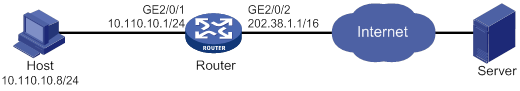
Configuration procedure
# Specify IP addresses for the interfaces on the router. (Details not shown.)
# Configure a one-to-one static NAT mapping between the private address 10.110.10.8 and the public address 202.38.1.100.
<Router> system-view
[Router] nat static outbound 10.110.10.8 202.38.1.100
# Enable static NAT on GigabitEthernet 2/0/2.
[Router] interface gigabitethernet 2/0/2
[Router-GigabitEthernet2/0/2] nat static enable
[Router-GigabitEthernet2/0/2] quit
Verifying the configuration
# Verify that the host at 10.110.10.8/24 can access the server on the Internet. (Details not shown.)
# Display static NAT configuration.
[Router] display nat static
Static NAT mappings:
Totally 1 outbound static NAT mappings.
IP-to-IP:
Local IP : 10.110.10.8
Global IP : 202.38.1.100
Config status: Active
Interfaces enabled with static NAT:
Totally 1 interfaces enabled with static NAT.
Interface: GigabitEthernet2/0/2
Config status: Active
# Display NAT session information.
[Router] display nat session verbose
Slot 0:
Total sessions found: 0
Slot 2:
Initiator:
Source IP/port: 10.110.10.8/42496
Destination IP/port: 202.38.1.111/2048
DS-Lite tunnel peer: -
VPN instance/VLAN ID/Inline ID: -/-/-
Protocol: ICMP(1)
Inbound interface: GigabitEthernet2/0/1
Responder:
Source IP/port: 202.38.1.111/42496
Destination IP/port: 202.38.1.100/0
DS-Lite tunnel peer: -
VPN instance/VLAN ID/Inline ID: -/-/-
Protocol: ICMP(1)
Inbound interface: GigabitEthernet2/0/2
State: ICMP_REPLY
Application: INVALID
Rule ID: -/-/-
Rule name:
Start time: 2012-08-16 09:30:49 TTL: 27s
Initiator->Responder: 5 packets 420 bytes
Responder->Initiator: 5 packets 420 bytes
Total sessions found: 1
Outbound dynamic NAT configuration example (non-overlapping addresses)
Network requirements
As shown in Figure 65, a company has a private address 192.168.0.0/16 and two public IP addresses 202.38.1.2 and 202.38.1.3. Configure outbound dynamic NAT to allow only internal users on subnet 192.168.1.0/24 to access the Internet.
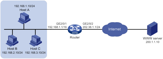
Configuration procedure
# Specify IP addresses for the interfaces on the router. (Details not shown.)
# Configure address group 0, and add an address range from 202.38.1.2 to 202.38.1.3 to the group.
<Router> system-view
[Router] nat address-group 0
[Router-address-group-0] address 202.38.1.2 202.38.1.3
[Router-address-group-0] quit
# Configure ACL 2000, and create a rule to permit packets only from subnet 192.168.1.0/24 to pass through.
[Router] acl basic 2000
[Router-acl-ipv4-basic-2000] rule permit source 192.168.1.0 0.0.0.255
[Router-acl-ipv4-basic-2000] quit
# Enable outbound dynamic PAT on interface GigabitEthernet 2/0/2. The source IP addresses of the packets permitted by the ACL rule is translated into the addresses in address group 0.
[Router] interface gigabitethernet 2/0/2
[Router-GigabitEthernet2/0/2] nat outbound 2000 address-group 0
[Router-GigabitEthernet2/0/2] quit
Verifying the configuration
# Verify that Host A can access the WWW server, while Host B cannot. (Details not shown.)
# Display all NAT configuration and statistics.
[Router] display nat all
NAT address group information:
Totally 1 NAT address groups.
Address group ID: 0
Port range: 1-65535
Address information:
Start address End address
202.38.1.2 202.38.1.3
NAT outbound information:
Totally 1 NAT outbound rules.
Interface: GigabitEthernet2/0/2
ACL: 2000
Address group ID: 0
Port-preserved: N NO-PAT: N Reversible: N
Config status: Active
Global flow-table status: Active
Static NAT mappings:
Totally 1 outbound static NAT mappings.
IP-to-IP:
Local IP : 10.110.10.8
Global IP : 202.38.1.100
Config status : Active
NAT logging:
Log enable : Disabled
Flow-begin : Disabled
Flow-end : Disabled
Flow-active : Disabled
Port-block-assign : Disabled
Port-block-withdraw : Disabled
Alarm : Disabled
NAT mapping behavior:
Mapping mode : Address and Port-Dependent
ACL : ---
Config status: Active
NAT ALG:
DNS : Enabled
FTP : Enabled
H323 : Disabled
ICMP-ERROR : Enabled
ILS : Disabled
MGCP : Disabled
NBT : Disabled
PPTP : Enabled
RTSP : Enabled
RSH : Disabled
SCCP : Disabled
SIP : Disabled
SQLNET : Disabled
TFTP : Disabled
XDMCP : Disabled
Static NAT load balancing: Disabled
# Display NAT session information generated when Host A accesses the WWW server.
[Router] display nat session verbose
Slot 0:
Total sessions found: 0
Slot 2:
Initiator:
Source IP/port: 192.168.1.10/52992
Destination IP/port: 200.1.1.10/2048
DS-Lite tunnel peer: -
VPN instance/VLAN ID/Inline ID: -/-/-
Protocol: ICMP(1)
Inbound interface: GigabitEthernet2/0/1
Responder:
Source IP/port: 200.1.1.10/4
Destination IP/port: 202.38.1.3/0
DS-Lite tunnel peer: -
VPN instance/VLAN ID/Inline ID: -/-/-
Protocol: ICMP(1)
Inbound interface: GigabitEthernet2/0/2
State: ICMP_REPLY
Application: INVALID
Rule ID: -/-/-
Rule name:
Start time: 2012-08-15 14:53:29 TTL: 12s
Initiator->Responder: 1 packets 84 bytes
Responder->Initiator: 1 packets 84 bytes
Total sessions found: 1
Outbound bidirectional NAT configuration example
Network requirements
As shown in Figure 66, the private network where the Web server resides overlaps with the company private network 192.168.1.0/24. The company has two public IP addresses 202.38.1.2 and 202.38.1.3. Configure NAT to allow internal users to access the external Web server by using the server's domain name.
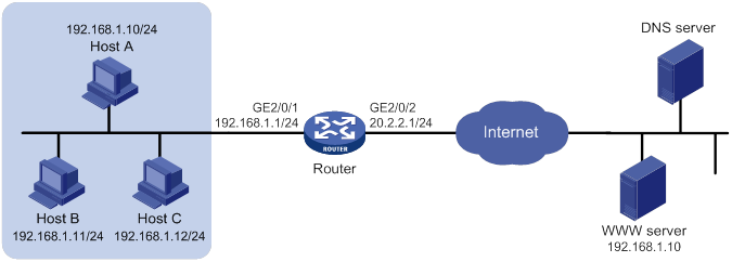
Requirements analysis
To meet the network requirements, you must perform the following tasks:
· Configure inbound dynamic NAT ALG to make sure the internal host reaches the Web server instead of another internal host. NAT ALG can translate the Web server's IP address in the DNS reply payload to a dynamically assigned public address.
· Configure outbound dynamic NAT to translate the source IP address of packets from an internal host to a dynamically assigned public address.
· Add a static route to the public IP address of the external Web server.
Configuration procedure
# Specify IP addresses for the interfaces on the router. (Details not shown.)
# Enable NAT ALG and DNS.
<Router> system-view
[Router] nat alg dns
# Configure ACL 2000, and create a rule to permit packets only from subnet 192.168.1.0/24 to pass through.
[Router] acl basic 2000
[Router-acl-ipv4-basic-2000] rule permit source 192.168.1.0 0.0.0.255
[Router-acl-ipv4-basic-2000] quit
# Create address group 1.
[Router] nat address-group 1
# Add address 202.38.1.2 to the group.
[Router-address-group-1] address 202.38.1.2 202.38.1.2
[Router-address-group-1] quit
# Create address group 2.
[Router] nat address-group 2
# Add address 202.38.1.3 to the group.
[Router-address-group-2] address 202.38.1.3 202.38.1.3
[Router-address-group-2] quit
# Enable inbound NO-PAT on interface GigabitEthernet 2/0/2 to translate the source IP address in the DNS reply payload into the address in address group 1, and allow reversible NAT.
[Router] interface gigabitethernet 2/0/2
[Router-GigabitEthernet2/0/2] nat inbound 2000 address-group 1 no-pat reversible
# Enable outbound PAT on interface GigabitEthernet 2/0/2 to translate the source address of outgoing packets into the address in address group 2.
[Router-GigabitEthernet2/0/2] nat outbound 2000 address-group 2
[Router-GigabitEthernet2/0/2] quit
# Configure a static route to 202.38.1.2 with GigabitEthernet 2/0/2 as the output interface and 20.2.2.2 as the next hop. (The next hop address varies by network.)
[Router] ip route-static 202.38.1.2 32 gigabitethernet 2/0/2 20.2.2.2
Verifying the configuration
# Verify that Host A can access the Web server by using its domain name. (Details not shown.)
# Display all NAT configuration and statistics.
[Router] display nat all
NAT address group information:
Totally 2 NAT address groups.
Address group ID: 1
Port range: 1-65535
Address information:
Start address End address
202.38.1.2 202.38.1.2
Address group ID: 2
Port range: 1-65535
Address information:
Start address End address
202.38.1.3 202.38.1.3
NAT inbound information:
Totally 1 NAT inbound rules.
Interface: GigabitEthernet2/0/2
ACL: 2000
Address group ID: 1
Add route: N NO-PAT: Y Reversible: Y
Config status: Active
NAT outbound information:
Totally 1 NAT outbound rules.
Interface: GigabitEthernet2/0/2
ACL: 2000
Address group ID: 2
Port-preserved: N NO-PAT: N Reversible: N
Config status: Active
NAT logging:
Log enable : Disabled
Flow-begin : Disabled
Flow-end : Disabled
Flow-active : Disabled
Port-block-assign : Disabled
Port-block-withdraw : Disabled
Alarm : Disabled
NAT mapping behavior:
Mapping mode : Address and Port-Dependent
ACL : ---
Config status: Active
NAT ALG:
DNS : Enabled
FTP : Enabled
H323 : Disabled
ICMP-ERROR : Enabled
ILS : Disabled
MGCP : Disabled
NBT : Disabled
PPTP : Enabled
RTSP : Enabled
RSH : Disabled
SCCP : Disabled
SIP : Disabled
SQLNET : Disabled
TFTP : Disabled
XDMCP : Disabled
Static NAT load balancing: Disabled
# Display NAT session information generated when Host A accesses the Web server.
[Router] display nat session verbose
Slot 0:
Total sessions found: 0
Slot 2:
Initiator:
Source IP/port: 192.168.1.10/1694
Destination IP/port: 202.38.1.2/8080
DS-Lite tunnel peer: -
VPN instance/VLAN ID/Inline ID: -/-/-
Protocol: TCP(6)
Inbound interface: GigabitEthernet2/0/1
Responder:
Source IP/port: 192.168.1.10/8080
Destination IP/port: 202.38.1.3/1025
DS-Lite tunnel peer: -
VPN instance/VLAN ID/Inline ID: -/-/-
Protocol: TCP(6)
Inbound interface: GigabitEthernet2/0/2
State: TCP_ESTABLISHED
Application: HTTP
Rule ID: -/-/-
Rule name:
Start time: 2012-08-15 14:53:29 TTL: 3597s
Initiator->Responder: 7 packets 308 bytes
Responder->Initiator: 5 packets 312 bytes
Total sessions found: 1
NAT Server for external-to-internal access configuration example
Network requirements
As shown in Figure 67, two Web servers, one FTP server and one SMTP server are in the internal network to provide services for external users. The internal network address is 10.110.0.0/16. The company has three public IP addresses from 202.38.1.1/24 to 202.38.1.3/24.
Configure the NAT Server feature to allow the external user to access the internal servers with public address 202.38.1.1/24.
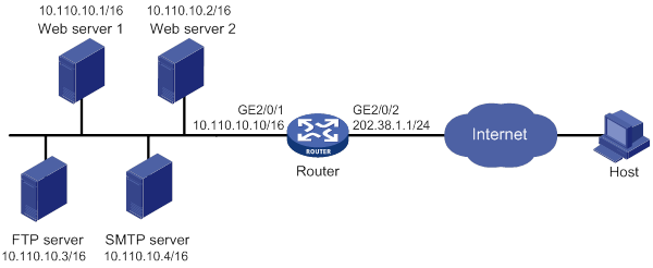
Configuration procedure
# Specify IP addresses for the interfaces on the router. (Details not shown.)
# Enter interface view of GigabitEthernet 2/0/2.
<Router> system-view
[Router] interface gigabitethernet 2/0/2
# Configure NAT Server to allow external users to access the FTP server by using the address 202.38.1.1 and port 21.
[Router-GigabitEthernet2/0/2] nat server protocol tcp global 202.38.1.1 21 inside 10.110.10.3 ftp
# Configure NAT Server to allow external users to access the Web server 1 by using the address 202.38.1.1 and port 80.
[Router-GigabitEthernet2/0/2] nat server protocol tcp global 202.38.1.1 80 inside 10.110.10.1 http
# Configure NAT Server to allow external users to access the Web server 2 by using the address 202.38.1.1 and port 8080.
[Router-GigabitEthernet2/0/2] nat server protocol tcp global 202.38.1.1 8080 inside 10.110.10.2 http
# Configure NAT Server to allow external users to access the SMTP server by using the address 202.38.1.1 and port number defined by SMTP.
[Router-GigabitEthernet2/0/2] nat server protocol tcp global 202.38.1.1 smtp inside 10.110.10.4 smtp
[Router-GigabitEthernet2/0/2] quit
Verifying the configuration
# Verify that the host on the external network can access the internal servers by using the public addresses. (Details not shown.)
# Display all NAT configuration and statistics.
[Router] display nat all
NAT internal server information:
Totally 4 internal servers.
Interface: GigabitEthernet2/0/2
Protocol: 6(TCP)
Global IP/port: 202.38.1.1/21
Local IP/port : 10.110.10.3/21
Config status : Active
Interface: GigabitEthernet2/0/2
Protocol: 6(TCP)
Global IP/port: 202.38.1.1/25
Local IP/port : 10.110.10.4/25
Config status : Active
Interface: GigabitEthernet2/0/2
Protocol: 6(TCP)
Global IP/port: 202.38.1.1/80
Local IP/port : 10.110.10.1/80
Config status : Active
Interface: GigabitEthernet2/0/2
Protocol: 6(TCP)
Global IP/port: 202.38.1.1/8080
Local IP/port : 10.110.10.2/80
Config status : Active
NAT logging:
Log enable : Disabled
Flow-begin : Disabled
Flow-end : Disabled
Flow-active : Disabled
Port-block-assign : Disabled
Port-block-withdraw : Disabled
Alarm : Disabled
NAT mapping behavior:
Mapping mode : Address and Port-Dependent
ACL : ---
Config status: Active
NAT ALG:
DNS : Enabled
FTP : Enabled
H323 : Disabled
ICMP-ERROR : Enabled
ILS : Disabled
MGCP : Disabled
NBT : Disabled
PPTP : Enabled
RTSP : Enabled
RSH : Disabled
SCCP : Disabled
SIP : Disabled
SQLNET : Disabled
TFTP : Disabled
XDMCP : Disabled
Static NAT load balancing: Disabled
# Display NAT session information generated when Host accesses the FTP server.
[Router] display nat session verbose
Slot 0:
Total sessions found: 0
Slot 2:
Initiator:
Source IP/port: 202.38.1.10/1694
Destination IP/port: 202.38.1.1/21
DS-Lite tunnel peer: -
VPN instance/VLAN ID/Inline ID: -/-/-
Protocol: TCP(6)
Inbound interface: GigabitEthernet2/0/2
Responder:
Source IP/port: 10.110.10.3/21
Destination IP/port: 202.38.1.10/1694
DS-Lite tunnel peer: -
VPN instance/VLAN ID/Inline ID: -/-/-
Protocol: TCP(6)
Inbound interface: GigabitEthernet2/0/1
State: TCP_ESTABLISHED
Application: FTP
Rule ID: -/-/-
Rule name:
Start time: 2012-08-15 14:53:29 TTL: 3597s
Initiator->Responder: 7 packets 308 bytes
Responder->Initiator: 5 packets 312 bytes
Total sessions found: 1
NAT Server for external-to-internal access through domain name configuration example
Network requirements
As shown in Figure 68, Web server at 10.110.10.2/24 in the internal network provides services for external users. A DNS server at 10.110.10.3/24 is used to resolve the domain name of the Web server. The company has two public IP addresses: 202.38.1.2 and 202.38.1.3.
Configure NAT Server to allow external users to access the internal Web server by using the domain name.
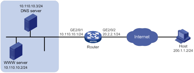
Requirements analysis
To meet the network requirements, you must perform the following tasks:
· Configure NAT Server to map the private IP address and port of the DNS server to a public address and port. NAT Server allows the external host to access the internal DNS server for domain name resolution.
· Enable ALG for DNS and configure outbound dynamic NAT to translate the private IP address of the Web server in the payload of the DNS response packet into a public IP address.
Configuration procedure
# Specify IP addresses for the interfaces on the router. (Details not shown.)
# Enable NAT ALG for DNS.
<Router> system-view
[Router] nat alg dns
# Configure ACL 2000, and create a rule to permit packets only from 10.110.10.2 to pass through.
[Router] acl basic 2000
[Router-acl-ipv4-basic-2000] rule permit source 10.110.10.2 0
[Router-acl-ipv4-basic-2000] quit
# Create address group 1.
[Router] nat address-group 1
# Add address 202.38.1.3 to the group.
[Router-address-group-1] address 202.38.1.3 202.38.1.3
[Router-address-group-1] quit
# Configure NAT Server on interface GigabitEthernet 2/0/2 to map the address 202.38.1.1 to 10.110.10.3. External users can access the internal DNS server.
[Router] interface gigabitethernet 2/0/2
[Router-GigabitEthernet2/0/2] nat server protocol udp global 202.38.1.2 inside 10.110.10.3 dns
# Enable outbound NO-PAT on interface GigabitEthernet 2/0/2. Use the address in address group 1 to translate the private address in DNS response payload, and allow reversible NAT.
[Router-GigabitEthernet2/0/2] nat outbound 2000 address-group 1 no-pat reversible
[Router-GigabitEthernet2/0/2] quit
Verifying the configuration
# Verify that the host on the external network can access the internal Web server by using the server's domain name. (Details not shown.)
# Display all NAT configuration and statistics.
[Router] display nat all
NAT address group information:
Totally 1 NAT address groups.
Address group ID: 1
Port range: 1-65535
Address information:
Start address End address
202.38.1.3 202.38.1.3
NAT outbound information:
Totally 1 NAT outbound rules.
Interface: GigabitEthernet2/0/2
ACL: 2000
Address group ID: 1
Port-preserved: N NO-PAT: Y Reversible: Y
Config status: Active
NAT internal server information:
Totally 1 internal servers.
Interface: GigabitEthernet2/0/2
Protocol: 17(UDP)
Global IP/port: 202.38.1.2/53
Local IP/port : 10.110.10.3/53
Config status : Active
NAT logging:
Log enable : Disabled
Flow-begin : Disabled
Flow-end : Disabled
Flow-active : Disabled
Port-block-assign : Disabled
Port-block-withdraw : Disabled
Alarm : Disabled
NAT mapping behavior:
Mapping mode : Address and Port-Dependent
ACL : ---
Config status: Active
NAT ALG:
DNS : Enabled
FTP : Enabled
H323 : Disabled
ICMP-ERROR : Enabled
ILS : Disabled
MGCP : Disabled
NBT : Disabled
PPTP : Enabled
RTSP : Enabled
RSH : Disabled
SCCP : Disabled
SIP : Disabled
SQLNET : Disabled
TFTP : Disabled
XDMCP : Disabled
Static NAT load balancing: Disabled
# Display NAT session information generated when Host accesses Web server.
[Router] display nat session verbose
Slot 0:
Total sessions found: 0
Slot 2:
Initiator:
Source IP/port: 202.1.1.2/1694
Destination IP/port: 202.38.1.3/8080
DS-Lite tunnel peer: -
VPN instance/VLAN ID/Inline ID: -/-/-
Protocol: TCP(6)
Inbound interface: GigabitEthernet2/0/2
Responder:
Source IP/port: 10.110.10.2/8080
Destination IP/port: 202.1.1.2/1694
DS-Lite tunnel peer: -
VPN instance/VLAN ID/Inline ID: -/-/-
Protocol: TCP(6)
Inbound interface: GigabitEthernet2/0/1
State: TCP_ESTABLISHED
Application: HTTP
Rule ID: -/-/-
Rule name:
Start time: 2012-08-15 14:53:29 TTL: 3597s
Initiator->Responder: 7 packets 308 bytes
Responder->Initiator: 5 packets 312 bytes
Total sessions found: 1
Bidirectional NAT for external-to-internal NAT Server access through domain name configuration example
Network requirements
As shown in Figure 69, an intranet uses the subnet 192.168.1.0/24. The Web server at 192.168.1.2/24 provides Web services for external users and the DNS server at 192.168.1.3/24 resolves the domain name of the Web server. The company has 3 public addresses 202.38.1.2, 202.38.1.3, and 202.38.1.4.
Configure NAT to allow external host at 192.168.1.2 in the external network to use the domain name to access the internal Web server.
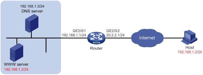
Requirements analysis
To meet the network requirements, you must perform the following tasks:
· Configure NAT Server to map the private IP address and port of the DNS server to a public IP address and port. NAT Server allows the external host to access the internal DNS server for domain name resolution.
· Configure outbound dynamic NAT and enable ALG for DNS. The Web server's IP address is the same as the external host's IP address. NAT ALG can translate the Web server's private address in the payload of the DNS response packet to a dynamically assigned public address.
· Configure inbound dynamic NAT. The external host's IP address is the same as the Web server's IP address. Inbound dynamic NAT can translate the external host's IP address into a dynamically assigned public address.
· Add a static route to the public IP address of the external host with GigabitEthernet 2/0/2 as the output interface.
Configuration procedure
# Specify IP addresses for the interfaces on the router. (Details not shown.)
# Enable NAT ALG for DNS.
<Router> system-view
[Router] nat alg dns
# Configure ACL 2000, and create a rule to permit packets only from subnet 192.168.1.0/24 to pass through.
[Router] acl basic 2000
[Router-acl-ipv4-basic-2000] rule permit source 192.168.1.0 0.0.0.255
[Router-acl-ipv4-basic-2000] quit
# Create address group 1.
[Router] nat address-group 1
# Add address 202.38.1.2 to the address group.
[Router-address-group-1] address 202.38.1.2 202.38.1.2
[Router-address-group-1] quit
# Create address group 2.
[Router] nat address-group 2
# Add address 202.38.1.3 to the address group.
[Router-address-group-2] address 202.38.1.3 202.38.1.3
[Router-address-group-2] quit
# Configure NAT Server on interface GigabitEthernet 2/0/2 to allow external hosts to access the internal DNS server by using the address 202.38.1.4.
[Router] interface gigabitethernet 2/0/2
[Router-GigabitEthernet2/0/2] nat server protocol udp global 202.38.1.4 inside 192.168.1.3 dns
# Enable outbound NO-PAT on interface GigabitEthernet 2/0/2 to translate IP address of the Web server in the DNS response payload into the address in address group 1, and allow reversible NAT.
[Router-GigabitEthernet2/0/2] nat outbound 2000 address-group 1 no-pat reversible
# Enable inbound PAT on interface GigabitEthernet 2/0/2 to translate the source address of packets going to the internal network to the address in address group 2.
[Router-GigabitEthernet2/0/2] nat inbound 2000 address-group 2
[Router-GigabitEthernet2/0/2] quit
# Configure a static route to 202.38.1.3 with GigabitEthernet 2/0/2 as the output interface and 20.2.2.2 as the next hop. (The next hop address varies by network.)
[Router] ip route-static 202.38.1.3 32 gigabitethernet 2/0/2 20.2.2.2
Verifying the configuration
# Verify that the host on the external network can use the domain name to access the internal Web server whose address is the same as the host. (Details not shown.)
# Display all NAT configuration and statistics.
[Router] display nat all
NAT address group information:
Totally 2 NAT address groups.
Address group ID: 1
Port range: 1-65535
Address information:
Start address End address
202.38.1.2 202.38.1.2
Address group ID: 2
Port range: 1-65535
Address information:
Start address End address
202.38.1.3 202.38.1.3
NAT inbound information:
Totally 1 NAT inbound rules.
Interface: GigabitEthernet2/0/2
ACL: 2000
Address group ID: 2
Add route: N NO-PAT: N Reversible: N
Config status: Active
NAT outbound information:
Totally 1 NAT outbound rules.
Interface: GigabitEthernet2/0/2
ACL: 2000
Address group ID: 1
Port-preserved: N NO-PAT: Y Reversible: Y
Config status: Active
NAT internal server information:
Totally 1 internal servers.
Interface: GigabitEthernet2/0/2
Protocol: 17(UDP)
Global IP/port: 202.38.1.4/53
Local IP/port : 200.1.1.3/53
Config status : Active
NAT logging:
Log enable : Disabled
Flow-begin : Disabled
Flow-end : Disabled
Flow-active : Disabled
Port-block-assign : Disabled
Port-block-withdraw : Disabled
Alarm : Disabled
NAT mapping behavior:
Mapping mode : Address and Port-Dependent
ACL : ---
Config status: Active
NAT ALG:
DNS : Enabled
FTP : Enabled
H323 : Disabled
ICMP-ERROR : Enabled
ILS : Disabled
MGCP : Disabled
NBT : Disabled
PPTP : Enabled
RTSP : Enabled
RSH : Disabled
SCCP : Disabled
SIP : Disabled
SQLNET : Disabled
TFTP : Disabled
XDMCP : Disabled
Static NAT load balancing: Disabled
# Display NAT session information generated when Host accesses the Web server.
[Router] display nat session verbose
Slot 0:
Total sessions found: 0
Slot 2:
Initiator:
Source IP/port: 192.168.1.2/1694
Destination IP/port: 202.38.1.2/8080
DS-Lite tunnel peer: -
VPN instance/VLAN ID/Inline ID: -/-/-
Protocol: TCP(6)
Inbound interface: GigabitEthernet2/0/2
Responder:
Source IP/port: 192.168.1.2/8080
Destination IP/port: 202.38.1.3/1025
DS-Lite tunnel peer: -
VPN instance/VLAN ID/Inline ID: -/-/-
Protocol: TCP(6)
Inbound interface: GigabitEthernet2/0/1
State: TCP_ESTABLISHED
Application: HTTP
Rule ID: -/-/-
Rule name:
Start time: 2012-08-15 14:53:29 TTL: 3597s
Initiator->Responder: 7 packets 308 bytes
Responder->Initiator: 5 packets 312 bytes
Total sessions found: 1
NAT hairpin in C/S mode configuration example
Network requirements
As shown in Figure 70, the internal FTP server at 192.168.1.4/24 provides services for internal and external users. The private network uses two public IP addresses 202.38.1.1 and 202.38.1.2.
Configure NAT hairpin in C/S mode to allow external and internal users to access the internal FTP server by using public IP address 202.38.1.2.
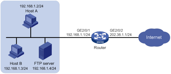
Requirements analysis
To allow external hosts to access the internal FTP server by using a public IP address, configure NAT Server on the interface connected to the external network.
To allow internal hosts to access the internal FTP server by using a public IP address, perform the following tasks:
· Enable NAT hairpin on the interface connected to the internal network.
· Configure outbound NAT on the interface where NAT Server is configured. The destination address is translated by matching the NAT Server. The source address is translated by matching the outbound NAT.
Configuration procedure
# Specify IP addresses for the interfaces on the router. (Details not shown.)
# Configure ACL 2000, and create a rule to permit packets only from subnet 192.168.1.0/24 to be translated.
<Router> system-view
[Router] acl basic 2000
[Router-acl-ipv4-basic-2000] rule permit source 192.168.1.0 0.0.0.255
[Router-acl-ipv4-basic-2000] quit
# Configure NAT Server on interface GigabitEthernet 2/0/2 to map the IP address of the FTP server to a public address, allowing external users to access the internal FTP server.
[Router] interface gigabitethernet 2/0/2
[Router-GigabitEthernet2/0/2] nat server protocol tcp global 202.38.1.2 inside 192.168.1.4 ftp
# Enable outbound NAT with Easy IP on GigabitEthernet 2/0/2 so that NAT translates the source addresses of the packets from internal hosts into the IP address of interface GigabitEthernet 1/0/2.
[Router-GigabitEthernet2/0/2] nat outbound 2000
[Router-GigabitEthernet2/0/2] quit
# Enable NAT hairpin on interface GigabitEthernet 2/0/1.
[Router] interface gigabitethernet 2/0/1
[Router-GigabitEthernet2/0/1] nat hairpin enable
[Router-GigabitEthernet2/0/1] quit
Verifying the configuration
# Verify that both internal and external hosts can access the internal FTP server through the public address. (Details not shown.)
# Display all NAT configuration and statistics.
[Router]display nat all
NAT outbound information:
Totally 1 NAT outbound rules.
Interface: GigabitEthernet2/0/2
ACL: 2000
Address group ID: ---
Port-preserved: N NO-PAT: N Reversible: N
Config status: Active
NAT internal server information:
Totally 1 internal servers.
Interface: GigabitEthernet2/0/2
Protocol: 6(TCP)
Global IP/port: 202.38.1.2/21
Local IP/port : 192.168.1.4/21
Config status : Active
NAT logging:
Log enable : Disabled
Flow-begin : Disabled
Flow-end : Disabled
Flow-active : Disabled
Port-block-assign : Disabled
Port-block-withdraw : Disabled
Alarm : Disabled
NAT hairpinning:
Totally 1 interfaces enabled with NAT hairpinning.
Interface: GigabitEthernet2/0/1
Config status: Active
NAT mapping behavior:
Mapping mode : Address and Port-Dependent
ACL : ---
Config status: Active
NAT ALG:
DNS : Enabled
FTP : Enabled
H323 : Disabled
ICMP-ERROR : Enabled
ILS : Disabled
MGCP : Disabled
NBT : Disabled
PPTP : Enabled
RTSP : Enabled
RSH : Disabled
SCCP : Disabled
SIP : Disabled
SQLNET : Disabled
TFTP : Disabled
XDMCP : Disabled
Static NAT load balancing: Disabled
# Display NAT session information generated when Host A accesses the FTP server.
[Router] display nat session verbose
Slot 0:
Total sessions found: 0
Slot 2:
Initiator:
Source IP/port: 192.168.1.2/1694
Destination IP/port: 202.38.1.2/21
DS-Lite tunnel peer: -
VPN instance/VLAN ID/Inline ID: -/-/-
Protocol: TCP(6)
Inbound interface: GigabitEthernet2/0/1
Responder:
Source IP/port: 192.168.1.4/21
Destination IP/port: 202.38.1.1/1025
DS-Lite tunnel peer: -
VPN instance/VLAN ID/Inline ID: -/-/-
Protocol: TCP(6)
Inbound interface: GigabitEthernet2/0/1
State: TCP_ESTABLISHED
Application: FTP
Rule ID: -/-/-
Rule name:
Start time: 2012-08-15 14:53:29 TTL: 3597s
Initiator->Responder: 7 packets 308 bytes
Responder->Initiator: 5 packets 312 bytes
NAT hairpin in P2P mode configuration example
Network requirements
In the P2P application, internal clients must register their IP address to the external server and the server records the registered IP addresses and port numbers of the internal clients. An internal client must request the IP address and port number of another client from the external server before accessing the client.
Configure NAT hairpin so that:
· The internal clients can register the same public address to the external server.
· The internal clients can access each other through the IP address and port number obtained from the server.
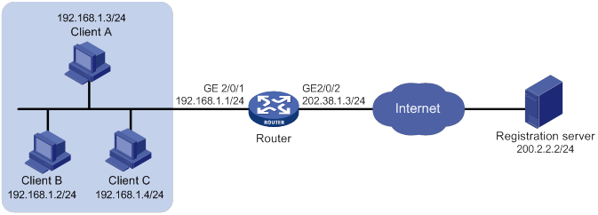
Requirements analysis
To meet the network requirements, you must perform the following tasks:
· Configure outbound dynamic PAT on the interface connected to the external network, so the internal clients can access the external server for registration.
· Configure the mapping behavior for PAT as Endpoint-Independent Mapping because the registered IP address and port number should be accessible for any source address.
· Enable NAT hairpin on the interface connected to the internal network so that internal clients can access each other through the public address.
Configuration procedure
# Specify IP addresses for the interfaces on the router. (Details not shown.)
# Configure ACL 2000, and create a rule to permit packets only from subnet 192.168.1.0/24 to be translated.
<Router> system-view
[Router] acl basic 2000
[Router-acl-ipv4-basic-2000] rule permit source 192.168.1.0 0.0.0.255
[Router-acl-ipv4-basic-2000] quit
# Configure outbound dynamic PAT with Easy IP on interface GigabitEthernet 2/0/2. The IP address of GigabitEthernet 2/0/2 is used as the public address for the source address translation of the packets from internal to external.
[Router] interface gigabitethernet 2/0/2
[Router-GigabitEthernet2/0/2] nat outbound 2000
[Router-GigabitEthernet2/0/2] quit
# Configure the Endpoint-Independent Mapping mode for PAT. For packets with the same source address and port number and permitted by ACL 2000, the source address and port number are translated to the same public address and port number.
[Router] nat mapping-behavior endpoint-independent acl 2000
# Enable NAT hairpin on interface GigabitEthernet 2/0/1.
[Router] interface gigabitethernet 2/0/1
[Router-GigabitEthernet2/0/1] nat hairpin enable
[Router-GigabitEthernet2/0/1] quit
Verifying the configuration
# Verify that Host A, Host B, and Host C can access each other after they register their IP addresses and port numbers to the external server. (Details not shown.)
# Display all NAT configuration and statistics.
[Router] display nat all
NAT outbound information:
Totally 1 NAT outbound rules.
Interface: GigabitEthernet2/0/2
ACL: 2000
Address group ID: ---
Port-preserved: N NO-PAT: N Reversible: N
Config status: Active
NAT logging:
Log enable : Disabled
Flow-begin : Disabled
Flow-end : Disabled
Flow-active : Disabled
Port-block-assign : Disabled
Port-block-withdraw : Disabled
Alarm : Disabled
NAT hairpinning:
Totally 1 interfaces enabled with NAT hairpinning.
Interface: GigabitEthernet2/0/1
Config status: Active
NAT mapping behavior:
Mapping mode : Endpoint-Independent
ACL : 2000
Config status: Active
NAT ALG:
DNS : Enabled
FTP : Enabled
H323 : Disabled
ICMP-ERROR : Enabled
ILS : Disabled
MGCP : Disabled
NBT : Disabled
PPTP : Enabled
RTSP : Enabled
RSH : Disabled
SCCP : Disabled
SIP : Disabled
SQLNET : Disabled
TFTP : Disabled
XDMCP : Disabled
Static NAT load balancing: Disabled
# Display NAT session information generated when Client A accesses Client B.
[Router] display nat session verbose
Slot 0:
Total sessions found: 0
Slot 2:
Initiator:
Source IP/port: 192.168.1.3/44929
Destination IP/port: 202.38.1.3/1
DS-Lite tunnel peer: -
VPN instance/VLAN ID/Inline ID: -/-/-
Protocol: UDP(17)
Inbound interface: GigabitEthernet2/0/1
Responder:
Source IP/port: 192.168.1.2/69
Destination IP/port: 202.38.1.3/1024
DS-Lite tunnel peer: -
VPN instance/VLAN ID/Inline ID: -/-/-
Protocol: UDP(17)
Inbound interface: GigabitEthernet2/0/1
State: UDP_READY
Application: TFTP
Rule ID: -/-/-
Rule name:
Start time: 2012-08-15 15:53:36 TTL: 46s
Initiator->Responder: 1 packets 56 bytes
Responder->Initiator: 1 packets 72 bytes
Total sessions found: 1
Twice NAT configuration example
Network requirements
As shown in Figure 72, two departments are in different VPN instances with overlapping addresses. Configure twice NAT so that Host A and Host B in different departments can access each other.
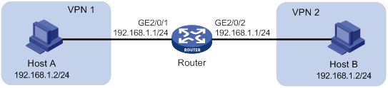
Requirements analysis
This is a typical application of twice NAT. Both the source and destination addresses of packets between the two VPNs need to be translated. Configure static NAT on both interfaces connected to the VPNs on the NAT device.
Configuration procedure
# Specify VPN instances and IP addresses for the interfaces on the router. (Details not shown.)
# Configure a static outbound NAT mapping between 192.168.1.2 in vpn 1 and 172.16.1.2 in vpn 2.
<Router> system-view
[Router] nat static outbound 192.168.1.2 vpn-instance vpn1 172.16.1.2 vpn-instance vpn2
# Configure a static outbound NAT mapping between 192.168.1.2 in vpn 2 and 172.16.2.2 in vpn 1.
[Router] nat static outbound 192.168.1.2 vpn-instance vpn2 172.16.2.2 vpn-instance vpn1
# Enable static NAT on interface GigabitEthernet 2/0/2.
[Router] interface gigabitethernet 2/0/2
[Router-GigabitEthernet2/0/2] nat static enable
[Router-GigabitEthernet2/0/2] quit
# Enable static NAT on interface GigabitEthernet 2/0/1.
[Router] interface gigabitethernet 2/0/1
[Router-GigabitEthernet2/0/1] nat static enable
[Router-GigabitEthernet2/0/1] quit
Verifying the configuration
# Verify that Host A and Host B can access each other. The public address for Host A is 172.16.1.2 and that for Host B is 172.16.2.2. (Details not shown.)
# Display all NAT configuration and statistics.
[Router] display nat all
Static NAT mappings:
Totally 2 outbound static NAT mappings.
IP-to-IP:
Local IP : 192.168.1.2
Global IP : 172.16.1.2
Local VPN : vpn1
Global VPN : vpn2
Config status: Active
IP-to-IP:
Local IP : 192.168.1.2
Global IP : 172.16.2.2
Local VPN : vpn2
Global VPN : vpn1
Config status: Active
Interfaces enabled with static NAT:
Totally 2 interfaces enabled with static NAT.
Interface: GigabitEthernet2/0/1
Config status: Active
Interface: GigabitEthernet2/0/2
Config status: Active
NAT logging:
Log enable : Disabled
Flow-begin : Disabled
Flow-end : Disabled
Flow-active : Disabled
Port-block-assign : Disabled
Port-block-withdraw : Disabled
Alarm : Disabled
NAT mapping behavior:
Mapping mode : Address and Port-Dependent
ACL : ---
Config status: Active
NAT ALG:
DNS : Enabled
FTP : Enabled
H323 : Disabled
ICMP-ERROR : Enabled
ILS : Disabled
MGCP : Disabled
NBT : Disabled
PPTP : Enabled
RTSP : Enabled
RSH : Disabled
SCCP : Disabled
SIP : Disabled
SQLNET : Disabled
TFTP : Disabled
XDMCP : Disabled
Static NAT load balancing: Disabled
# Display NAT session information generated when Host A accesses Host B.
[Router] display nat session verbose
Slot 0:
Total sessions found: 0
Slot 2:
Initiator:
Source IP/port: 192.168.1.2/42496
Destination IP/port: 172.16.2.2/2048
DS-Lite tunnel peer: -
VPN instance/VLAN ID/Inline ID: vpn1/-/-
Protocol: ICMP(1)
Inbound interface: GigabitEthernet2/0/1
Responder:
Source IP/port: 192.168.1.2/42496
Destination IP/port: 172.16.1.2/0
DS-Lite tunnel peer: -
VPN instance/VLAN ID/Inline ID: vpn2/-/-
Protocol: ICMP(1)
Inbound interface: GigabitEthernet2/0/2
State: ICMP_REPLY
Application: INVALID
Rule ID: -/-/-
Rule name:
Start time: 2012-08-16 09:30:49 TTL: 27s
Initiator->Responder: 5 packets 420 bytes
Responder->Initiator: 5 packets 420 bytes
Total sessions found: 1
Load sharing NAT Server configuration example
Network requirements
As shown in Figure 73, three FTP servers are in the intranet to provide FTP services for external users. Configure NAT so that these external users use the address 202.38.1.1/16 to access the servers and the three FTP servers implement load sharing.
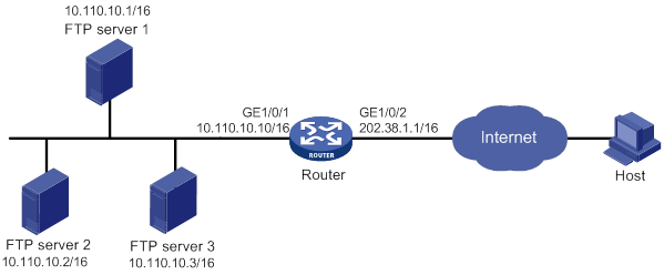
Configuration procedure
# Specify IP addresses for the interfaces on the router. (Details not shown.)
# Create NAT Server group 0, and add members to the group.
<Router> system-view
[Router] nat server-group 0
[Router-nat-server-group-0] inside ip 10.110.10.1 port 21
[Router-nat-server-group-0] inside ip 10.110.10.2 port 21
[Router-nat-server-group-0] inside ip 10.110.10.3 port 21
[Router-nat-server-group-0] quit
# Associate NAT Server group 0 with GigabitEthernet 1/0/2 so that servers in the server group can provide FTP services.
[Router] interface gigabitethernet 1/0/2
[Router-GigabitEthernet1/0/2] nat server protocol tcp global 202.38.1.1 ftp inside server-group 0
[Router-GigabitEthernet1/0/2] quit
Verifying the configuration
# Verify that external hosts can access the internal FTP server group. (Details not shown.)
# Display all NAT configuration and statistics.
[Router] display nat all
NAT server group information:
Totally 1 NAT server groups.
Group Number Inside IP Port Weight
0 10.110.10.1 21 100
10.110.10.2 21 100
10.110.10.3 21 100
NAT internal server information:
Totally 1 internal servers.
Interface: GigabitEthernet1/0/2
Protocol: 6(TCP)
Global IP/port: 202.38.1.1/21
Local IP/port : server group 0
10.110.10.1/21 (Connections: 1)
10.110.10.2/21 (Connections: 2)
10.110.10.3/21 (Connections: 2)
Config status : Active
Global flow-table status: Active
Local flow-table status: Active
NAT logging:
Log enable : Disabled
Flow-begin : Disabled
Flow-end : Disabled
Flow-active : Disabled
Port-block-assign : Disabled
Port-block-withdraw : Disabled
Alarm : Disabled
NAT mapping behavior:
Mapping mode : Address and Port-Dependent
ACL : ---
Config status: Active
NAT ALG:
DNS : Enabled
FTP : Enabled
H323 : Enabled
ICMP-ERROR : Enabled
ILS : Enabled
MGCP : Enabled
NBT : Enabled
PPTP : Enabled
RSH : Enabled
RTSP : Enabled
SCCP : Enabled
SIP : Enabled
SQLNET : Enabled
TFTP : Enabled
XDMCP : Enabled
Static NAT load balancing: Disabled
# Display NAT session information generated when external hosts access an internal FTP server.
[Router] display nat session verbose
Slot 0:
Total sessions found: 0
Slot 2:
Initiator:
Source IP/port: 202.38.1.25/53957
Destination IP/port: 202.38.1.1/21
DS-Lite tunnel peer: -
VPN instance/VLAN ID/Inline ID: -/-/-
Protocol: TCP(6)
Inbound interface: GigabitEthernet1/0/2
Responder:
Source IP/port: 10.110.10.3/21
Destination IP/port: 202.38.1.25/53957
DS-Lite tunnel peer: -
VPN instance/VLAN ID/Inline ID: -/-/-
Protocol: TCP(6)
Inbound interface: GigabitEthernet1/0/1
State: TCP_ESTABLISHED
Application: FTP
Rule ID: -/-/-
Rule name:
Start time: 2012-08-16 11:06:07 TTL: 26s
Initiator->Responder: 1 packets 60 bytes
Responder->Initiator: 2 packets 120 bytes
Total sessions found: 1
NAT DNS mapping configuration example
Network requirements
As shown in Figure 74, the internal Web server at 10.110.10.1/16 and FTP server at 10.110.10.2/16 provide services for external user. The company has three public addresses 202.38.1.1 through 202.38.1.3. The DNS server at 202.38.1.4 is on the external network.
Configure NAT so that:
· The public IP address 202.38.1.2 is used by external users to access the Web and FTP servers.
· External users can use the public address or domain name of internal servers to access them.
· Internal users can access the internal servers by using their domain names.
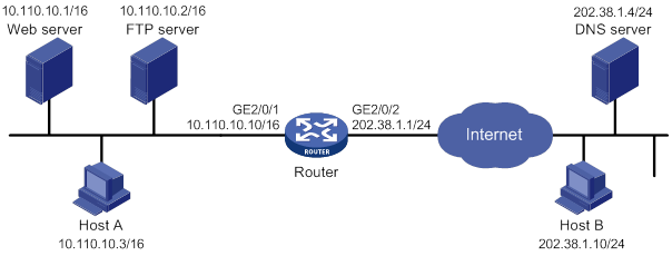
Requirements analysis
To meet the network requirements, perform the following tasks:
· Configure NAT Server by mapping the public IP addresses and port numbers of the internal servers to a public address and port numbers so that external users can access the internal servers.
· Configure NAT DNS mapping and ALG so that the public IP address of the internal server in the payload of the DNS response packet can be translated to the private IP address.
Configuration procedure
# Specify IP addresses for the interfaces on the router. (Details not shown.)
# Enable NAT ALG for DNS.
<Router> system-view
[Router] nat alg dns
# Enter interface view of GigabitEthernet 2/0/2.
[Router] interface gigabitethernet 2/0/2
# Configure NAT Server to allow external hosts to access the internal Web server by using the address 202.38.1.2.
[Router-GigabitEthernet2/0/2] nat server protocol tcp global 202.38.1.2 inside 10.110.10.1 http
# Configure NAT Server to allow external hosts to access the internal FTP server by using the address 202.38.1.2.
[Router-GigabitEthernet2/0/2] nat server protocol tcp global 202.38.1.2 inside 10.110.10.2 ftp
# Enable outbound NAT with Easy IP on GigabitEthernet 2/0/2.
[Router-GigabitEthernet2/0/2] nat outbound
[Router-GigabitEthernet2/0/2] quit
# Configure two DNS mapping entries by mapping the domain name www.server.com of the Web server to 202.38.1.2, and ftp.server.com of the FTP server to 202.38.1.2.
[Router] nat dns-map domain www.server.com protocol tcp ip 202.38.1.2 port http
[Router] nat dns-map domain ftp.server.com protocol tcp ip 202.38.1.2 port ftp
[Router] quit
Verifying the configuration
# Verify that both internal and external hosts can access the internal servers by using domain names. (Details not shown.)
# Display all NAT configuration and statistics.
[Router] display nat all
NAT outbound information:
Totally 1 NAT outbound rules.
Interface: GigabitEthernet2/0/2
ACL: ---
Address group ID: ---
Port-preserved: N NO-PAT: N Reversible: N
Config status: Active
NAT internal server information:
Totally 2 internal servers.
Interface: GigabitEthernet2/0/2
Protocol: 6(TCP)
Global IP/port: 202.38.1.2/21
Local IP/port : 10.110.10.2/21
Config status : Active
Interface: GigabitEthernet2/0/2
Protocol: 6(TCP)
Global IP/port: 202.38.1.2/80
Local IP/port : 10.110.10.1/80
Config status : Active
NAT DNS mapping information:
Totally 2 NAT DNS mappings.
Domain name: ftp.server.com
Global IP : 202.38.1.2
Global port: 21
Protocol : TCP(6)
Config status: Active
Domain name: www.server.com
Global IP : 202.38.1.2
Global port: 80
Protocol : TCP(6)
Config status: Active
NAT logging:
Log enable : Disabled
Flow-begin : Disabled
Flow-end : Disabled
Flow-active : Disabled
Port-block-assign : Disabled
Port-block-withdraw : Disabled
Alarm : Disabled
NAT mapping behavior:
Mapping mode: Address and Port-Dependent
ACL : ---
Config status: Active
NAT ALG:
DNS : Enabled
FTP : Enabled
H323 : Disabled
ICMP-ERROR : Enabled
ILS : Disabled
MGCP : Disabled
NBT : Disabled
PPTP : Enabled
RTSP : Enabled
RSH : Disabled
SCCP : Disabled
SIP : Disabled
SQLNET : Disabled
TFTP : Disabled
XDMCP : Disabled
Static NAT load balancing: Disabled
# Verify that NAT sessions have been created for external host access to the internal Web server.
[Router] display nat session verbose
Slot 0:
Total sessions found: 0
Slot 2:
Initiator:
Source IP/port: 202.38.1.10/63593
Destination IP/port: 202.38.1.2/80
DS-Lite tunnel peer: -
VPN instance/VLAN ID/Inline ID: -/-/-
Protocol: TCP(6)
Inbound interface: GigabitEthernet1/0/2
Responder:
Source IP/port: 10.110.10.1/80
Destination IP/port: 202.38.1.10/63593
DS-Lite tunnel peer: -
VPN instance/VLAN ID/Inline ID: -/-/-
Protocol: TCP(6)
Inbound interface: GigabitEthernet1/0/1
State: TCP_ESTABLISHED
Application: HTTP
Rule ID: -/-/-
Rule name:
Start time: 2012-08-26 14:53:29 TTL: 11s
Initiator->Responder: 5 packets 1145 bytes
Responder->Initiator: 3 packets 1664 bytes
Total sessions found: 1
Static NAT444 configuration example
Network requirements
As shown in Figure 75, configure static NAT444 to allow users at private IP addresses 10.110.10.1 to 10.110.10.10 to use public IP address 202.38.1.100 for accessing the Internet. Configure the port range as 10001 to 15000, and set the port block size to 500.
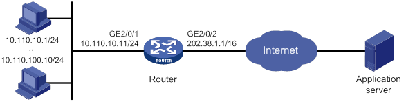
Configuration procedure
# Specify IP addresses for the interfaces on the router. (Details not shown.)
# Create NAT port block group 1.
<Router> system-view
[Router] nat port-block-group 1
# Add the private IP addresses from 10.110.10.1 to 10.110.10.10 to the port block group.
[Router-port-block-group-1] local-ip-address 10.110.10.1 10.110.10.10
# Add the public IP address 202.38.1.100 to the port block group.
[Router-port-block-group-1] global-ip-pool 202.38.1.100 202.38.1.100
# Set the port block size to 500.
[Router-port-block-group-1] block-size 500
# Configure the port range as 10001 to 15000.
[Router-port-block-group-1] port-range 10001 15000
[Router-port-block-group-1] quit
# Apply the port block group 1 to the outbound direction of GigabitEthernet 2/0/2.
[Router] interface gigabitethernet 2/0/2
[Router-GigabitEthernet2/0/2] nat outbound port-block-group 1
[Router-GigabitEthernet2/0/2] quit
Verifying the configuration
# Verify that users at the private IP addresses can access the Internet. (Details not shown.)
# Display all NAT configuration and statistics.
[Router] display nat all
NAT logging:
Log enable : Disabled
Flow-begin : Disabled
Flow-end : Disabled
Flow-active : Disabled
Port-block-assign : Disabled
Port-block-withdraw : Disabled
Alarm : Disabled
NAT mapping behavior:
Mapping mode : Address and Port-Dependent
ACL : ---
Config status: Active
NAT ALG:
DNS : Enabled
FTP : Enabled
H323 : Disabled
ICMP-ERROR : Enabled
ILS : Disabled
MGCP : Disabled
NBT : Disabled
PPTP : Enabled
RTSP : Enabled
RSH : Disabled
SCCP : Disabled
SIP : Disabled
SQLNET : Disabled
TFTP : Disabled
XDMCP : Disabled
NAT port block group information:
Totally 1 NAT port block groups.
Port block group 1:
Port range: 10001-15000
Block size: 500
Local IP address information:
Start address End address VPN instance
10.110.10.1 10.110.10.10 ---
Global IP pool information:
Start address End address
202.38.1.100 202.38.1.100
NAT outbound port block group information:
Totally 1 outbound port block group items.
Interface: GigabitEthernet2/0/2
port-block-group: 1
Config status : Active
Static NAT load balancing: Disabled
# Display static NAT444 mappings.
[Router] display nat port-block static
Slot 2:
Static port-block mapping tables:
Local VPN Local IP Global IP Port block Connections
--- 10.110.10.1 202.38.1.100 10001-10500 2
--- 10.110.10.2 202.38.1.100 10501-11000 0
--- 10.110.10.3 202.38.1.100 11001-11500 0
--- 10.110.10.4 202.38.1.100 11501-12000 0
--- 10.110.10.5 202.38.1.100 12001-12500 1
--- 10.110.10.6 202.38.1.100 12501-13000 0
--- 10.110.10.7 202.38.1.100 13001-13500 0
--- 10.110.10.8 202.38.1.100 13501-14000 0
--- 10.110.10.9 202.38.1.100 14001-14500 0
--- 10.110.10.10 202.38.1.100 14501-15000 0
Total mappings found: 10
Dynamic NAT444 configuration example
Network requirements
As shown in Figure 76, a company uses private IP address on network 192.168.0.0/16 and public IP addresses 202.38.1.2 and 202.38.1.3. Configure dynamic NAT444 to the following requirements:
· Only users on subnet 192.168.1.0/24 can use public IP addresses 202.38.1.2 and 202.38.1.3 to access the Internet.
· The port range for the public IP addresses is 1024 to 65535.
· The port block size is 300.
· If the ports in the assigned port block are all used, extend another port block for users.
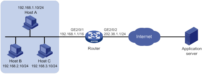
Configuration procedure
# Specify IP addresses for the interfaces on the router. (Details not shown.)
# Create public address group 0.
<Router> system-view
[Router] nat address-group 0
# Add the public IP addresses 202.38.1.2 and 202.38.1.3 to the NAT address group.
[Router-address-group-0] address 202.38.1.2 202.38.1.3
# Configure the port range as 1024 to 65535.
[Router-address-group-0] port-range 1024 65535
# Set the port block size to 300 and the extended port block number to 1.
[Router-address-group-0] port-block block-size 300 extended-block-number 1
[Router-address-group-0] quit
# Configure an ACL to identify packets from subnet 192.168.1.0/24.
[Router] acl basic 2000
[Router-acl-ipv4-basic-2000] rule permit source 192.168.1.0 0.0.0.255
[Router-acl-ipv4-basic-2000] quit
# Configure outbound NAT444 on interface GigabitEthernet 2/0/2.
[Router] interface gigabitethernet 2/0/2
[Router-GigabitEthernet2/0/2] nat outbound 2000 address-group 0
[Router-GigabitEthernet2/0/2] quit
Verifying the configuration
# Verify that Host A can access external servers, but Host B and Host C cannot. (Details not shown.)
# Display all NAT configuration and statistics.
[Router] display nat all
NAT address group information:
Totally 1 NAT address groups.
Address group ID: 0
Port range: 1024-65535
Port block size: 300
Extended block number: 1
Address information:
Start address End address
202.38.1.2 202.38.1.3
NAT outbound information:
Totally 1 NAT outbound rules.
Interface: GigabitEthernet2/0/2
ACL: 2000
Address group ID: 0
Port-preserved: N NO-PAT: N Reversible: N
Config status: Active
NAT logging:
Log enable : Disabled
Flow-begin : Disabled
Flow-end : Disabled
Flow-active : Disabled
Port-block-assign : Disabled
Port-block-withdraw : Disabled
Alarm : Disabled
NAT mapping behavior:
Mapping mode : Address and Port-Dependent
ACL : ---
Config status: Active
NAT ALG:
DNS : Enabled
FTP : Enabled
H323 : Disabled
ICMP-ERROR : Enabled
ILS : Disabled
MGCP : Disabled
NBT : Disabled
PPTP : Enabled
RTSP : Enabled
RSH : Disabled
SCCP : Disabled
SIP : Disabled
SQLNET : Disabled
TFTP : Disabled
XDMCP : Disabled
Static NAT load balancing: Disabled
# Display NAT statistics.
[Router] display nat statistics
Total session entries: 1
Session creation rate: 0
Total EIM entries: 0
Total inbound NO-PAT entries: 0
Total outbound NO-PAT entries: 0
Total static port block entries: 0
Total dynamic port block entries: 430
Active static port block entries: 0
Active dynamic port block entries: 1
# Display the dynamic port block entries.
[Router] display nat port-block dynamic
Slot 0:
Local VPN Local IP Global IP Port block Connections
Total mappings found: 0
Slot 2:
Local VPN Local IP Global IP Port block Connections
--- 192.168.1.10 202.38.1.2 65224-65523 1
Total mappings found: 1
DS-Lite NAT444 configuration example
Network requirements
As shown in Figure 77, configure DS-Lite tunneling and NAT to allow the DS-Lite host to access the IPv4 network over the IPv6 network.
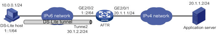
Configuration procedure
Before configuration, make sure the DS-Lite host and AFTR can reach each other through IPv6.
1. Configure the AFTR:
# Specify an IPv4 address for GigabitEthernet 2/0/1.
<Router> system-view
[Router] interface gigabitethernet 2/0/1
[Router-GigabitEthernet2/0/1] ip address 20.1.1.1 24
[Router-GigabitEthernet2/0/1] quit
# Specify an IPv6 address for GigabitEthernet 2/0/2.
[Router] interface gigabitethernet 2/0/2
[Router-GigabitEthernet2/0/2] ipv6 address 1::2 64
[Router-GigabitEthernet2/0/2] quit
# Create a tunnel interface on the AFTR.
[Router] interface tunnel 2 mode ds-lite-aftr
# Specify an IP address for the tunnel interface.
[Router-Tunnel2] ip address 30.1.2.2 255.255.255.0
# Specify GigabitEthernet 2/0/2 as the source interface for the tunnel.
[Router-Tunnel2] source gigabitethernet 2/0/2
[Router-Tunnel2] quit
# Enable DS-Lite tunneling on GigabitEthernet 2/0/1.
[Router] interface gigabitethernet 2/0/1
[Router-GigabitEthernet2/0/1] ds-lite enable
[Router-GigabitEthernet2/0/1] quit
# Create public address group 0.
[Router] nat address-group 0
# Add public IP addresses 20.1.1.11 and 20.1.1.12 to the NAT address group.
[Router-address-group-0] address 20.1.1.11 20.1.1.12
# Configure the port range as 1024 to 65535.
[Router-address-group-0] port-range 1024 65535
# Set the port block size to 300.
[Router-address-group-0] port-block block-size 300
[Router-address-group-0] quit
# Configure an IPv6 ACL to identify packets from subnet 1::/64.
[Router] acl ipv6 basic 2100
[Router-acl-ipv4-basic-2100] rule permit source 1::/64
[Router-acl-ipv4-basic-2100] quit
# Configure DS-Lite NAT444 on GigabitEthernet 2/0/1.
[Router] interface gigabitethernet 2/0/1
[Router-GigabitEthernet2/0/1] nat outbound ds-lite-b4 2100 address-group 0
[Router-GigabitEthernet2/0/1] quit
2. Configure the DS-Lite host:
# Configure the IPv4 and IPv6 addresses of the DS-Lite host as 10.0.0.1 and 1::1/64. (Details not shown.)
# Configure a static route to the destination IPv4 network. (Details not shown.)
Verifying the configuration
# Use the display tunnel interface command to verify that the tunnel interface is up on the AFTR. (Details not shown.)
# Verify that the DS-Lite host can ping the IPv4 application server.
C:\> ping 20.1.1.2
Pinging 20.1.1.2 with 32 bytes of data:
Reply from 20.1.1.2: bytes=32 time=51ms TTL=255
Reply from 20.1.1.2: bytes=32 time=44ms TTL=255
Reply from 20.1.1.2: bytes=32 time=1ms TTL=255
Reply from 20.1.1.2: bytes=32 time=1ms TTL=255
Ping statistics for 20.1.1.2:
Packets: Sent = 4, Received = 4, Lost = 0 (0% loss),
Approximate round trip times in milli-seconds:
Minimum = 1ms, Maximum = 51ms, Average = 24ms
# Verify that the DS-Lite NAT444 configuration is correct.
[Router] display nat outbound
NAT outbound information:
Totally 1 NAT outbound rules.
Interface: GigabitEthernet2/0/1
DS-Lite B4 ACL: 2100
Address group ID: 0
Port-preserved: N NO-PAT: N Reversible: N
Config status: Active
# Verify that the DS-Lite NAT444 configuration takes effect by checking the port block assignment.
[Router] display nat statistics
Slot 1:
Total session entries: 1
Session creation rate: 0
Total EIM entries: 0
Total inbound NO-PAT entries: 0
Total outbound NO-PAT entries: 0
Total static port block entries: 0
Total dynamic port block entries: 430
Active static port block entries: 0
Active dynamic port block entries: 1
# Verify that a NAT444 mapping has been created for the DS-Lite host.
[Router] display nat port-block dynamic ds-lite-b4
Slot 1:
Local VPN DS-Lite B4 addr Global IP Port block Connections
--- 1::1 20.1.1.11 1024-1323 1
Total mappings found: 1
Basic IP forwarding on the device
The device uses the destination IP address of a received packet to find a match from the forwarding information base (FIB) table. It then uses the matching entry to forward the packet.
FIB table
A device selects optimal routes from the routing table, and puts them into the FIB table. Each FIB entry specifies the next hop IP address and output interface for packets destined for a specific subnet or host.
For more information about the routing table, see Layer 3—IP Routing Configuration Guide.
Use the display fib command to display FIB table entries. The following example displays the entire FIB table.
<Sysname> display fib
Destination count: 4 FIB entry count: 4
Flag:
U:Useable G:Gateway H:Host B:Blackhole D:Dynamic S:Static
R:Relay F:FRR
Destination/Mask Nexthop Flag OutInterface/Token Label
0.0.0.0/32 127.0.0.1 UH InLoop0 Null
10.2.0.0/16 10.2.1.1 U GE2/0/1 Null
10.2.1.1/32 127.0.0.1 UH InLoop0 Null
127.0.0.0/8 127.0.0.1 U InLoop0 Null
127.0.0.1/32 127.0.0.1 UH InLoop0 Null
A FIB entry includes the following items:
· Destination—Destination IP address.
· Mask—Network mask. The mask and the destination address identify the destination network. A logical AND operation between the destination address and the network mask yields the address of the destination network. For example, if the destination address is 192.168.1.40 and the mask 255.255.255.0, the address of the destination network is 192.168.1.0. A network mask includes a certain number of consecutive 1s. It can be expressed in dotted decimal format or by the number of the 1s.
· Nexthop—IP address of the next hop.
· Flag—Route flag.
· OutInterface—Output interface.
· Token—MPLS Label Switched Path index number.
· Label—Inner label.
Configuring last hop holding
Last hop holding implements symmetric routing. It tracks the last hop MAC address for a connection's first outgoing IP packet, and sends the return packets to the hop that transmitted the request.
As is shown in Figure 78, when the external server sends a request to the internal server, the packet travels through ISP 1 to Interface A on the device. The last hop holding feature on the device ensures that the reply packet follows the same route as the request packet back to ISP 1. If last hop holding is disabled, the reply packet might be sent out of Interface B or Interface C to the external network.
Figure 78 Last hop holding application
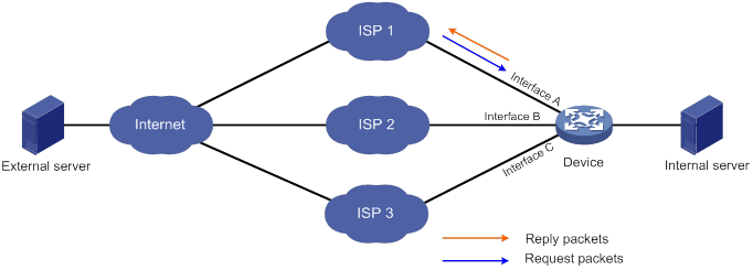
This feature is based on fast forwarding entries. If the MAC address of a last hop changes, this feature can function correctly only after the fast forwarding entry is updated for the MAC address.
This feature is not applicable to an MPLS network.
To configure last hop holding:
|
Step |
Command |
Remarks |
|
1. Enter system view. |
system-view |
N/A |
|
2. Enter Layer 3 Ethernet interface view or subinterface view. |
interface interface-type interface-number |
N/A |
|
3. Enable last hop holding. |
ip last-hop hold |
By default, last hop holding is disabled. |
|
|
NOTE: Last hop holding will make PBR ineffective on the interface for return packets, and the interface does not process the Options field in the return packets. For more information about PBR, see Layer 3—IP Routing Configuration Guide. |
Displaying FIB table entries
Execute display commands in any view.
|
Task |
Command |
|
Display FIB entries. |
display fib [ topology topology-name | vpn-instance vpn-instance-name ] [ ip-address [ mask | mask-length ] ] |
Configuring load sharing
If a routing protocol finds multiple equal-cost best routes to the same destination, the device forwards packets over the equal-cost routes to implement load sharing.
Command and hardware compatibility
Commands and descriptions for centralized devices apply to the following routers:
· MSR810/810-W/810-W-DB/810-LM/810-W-LM/810-10-PoE/810-LM-HK/810-W-LM-HK/810-LMS/810-LUS.
· MSR2600-6-X1/2600-10-X1.
· MSR 2630.
· MSR3600-28/3600-51.
· MSR3600-28-SI/3600-51-SI.
· MSR3610-X1/3610-X1-DP/3610-X1-DC/3610-X1-DP-DC.
· MSR 3610/3620/3620-DP/3640/3660.
· MSR810-LM-GL/810-W-LM-GL/830-6EI-GL/830-10EI-GL/830-6HI-GL/830-10HI-GL/2600-6-X1-GL/3600-28-SI-GL.
Commands and descriptions for distributed devices apply to the following routers:
· MSR5620.
· MSR 5660.
· MSR 5680.
Configuring per-packet or per-flow load sharing
Load sharing can be implemented in one of the following ways:
· Per-packet—The device forwards packets over equal-cost routes.
· Per-flow—The device forwards flows over equal-cost routes. Packets of one flow travel along the same routes. You can configure the device to identify a flow based on the following criteria: source IP address, destination IP address, source port number, destination port number, IP protocol number, and ingress port.
In a complex network, when the five tuples cannot distinguish flows, you can use the algorithm keyword to specify an algorithm to identify flows.
To configure per-flow or per-packet load sharing:
|
Step |
Command |
Remarks |
|
1. Enter system view. |
system-view |
N/A |
|
2. Configure load sharing. |
·
Centralized devices in standalone mode: ·
Distributed devices in standalone mode/centralized
devices in IRF mode: ·
Distributed devices in IRF mode: |
By default, the device does not perform load sharing. |
Configuring load sharing based on bandwidth
This feature load shares flow traffic among multiple output interfaces based on their load percentages. The device calculates the load percentage for each output interface in terms of the interface expected bandwidth.
Devices that run load sharing protocols, such as Locator/ID Separation Protocol (LISP), implement load sharing based on the ratios defined by these protocols.
To configure load sharing based on bandwidth:
|
Step |
Command |
Remarks |
|
1. Enter system view. |
system-view |
N/A |
|
2. Enable IPv4 load sharing based on bandwidth. |
By default, the IPv4 load sharing based on bandwidth is disabled. |
|
|
3. Enter interface view. |
N/A |
|
|
4. Configure the expected bandwidth of the interface. |
By default, the expected bandwidth is the physical bandwidth of the interface. |
Configuring fast forwarding
Overview
Fast forwarding reduces route lookup time and improves packet forwarding efficiency by using a high-speed cache and data-flow-based technology. It identifies a data flow by using the packet information (for example, source IP address, source port number, destination IP address, destination port number, and protocol number). After a flow's first packet is forwarded through the routing table, fast forwarding creates an entry and uses the entry to forward subsequent packets of the flow.
Fast forwarding can process fragmented IP packets, but it does not fragment IP packets.
Command and hardware compatibility
Commands and descriptions for centralized devices apply to the following routers:
· MSR810/810-W/810-W-DB/810-LM/810-W-LM/810-10-PoE/810-LM-HK/810-W-LM-HK/810-LMS/810-LUS.
· MSR2600-6-X1/2600-10-X1.
· MSR 2630.
· MSR3600-28/3600-51.
· MSR3600-28-SI/3600-51-SI.
· MSR3610-X1/3610-X1-DP/3610-X1-DC/3610-X1-DP-DC.
· MSR 3610/3620/3620-DP/3640/3660.
· MSR810-LM-GL/810-W-LM-GL/830-6EI-GL/830-10EI-GL/830-6HI-GL/830-10HI-GL/2600-6-X1-GL/3600-28-SI-GL.
Commands and descriptions for distributed devices apply to the following routers:
· MSR5620.
· MSR 5660.
· MSR 5680.
Configuring the aging time for fast forwarding entries
The fast forwarding table uses an aging timer for each forwarding entry. If an entry is not updated before the timer expires, the device deletes the entry. If an entry has a hit within the aging time, the aging timer restarts.
To configure the aging time for fast forwarding entries:
|
Step |
Command |
Remarks |
|
1. Enter system view. |
system-view |
N/A |
|
2. Configure the aging time for fast forwarding entries. |
ip fast-forwarding aging-time aging-time |
By default, the aging time is 30 seconds. |
Configuring fast forwarding load sharing
Fast forwarding load sharing enables the device to load share packets of the same flow. This feature identifies a data flow by using the packet information.
If fast forwarding load sharing is disabled, the device identifies a data flow by using the packet information and the input interface. No load sharing is implemented.
To configure fast forwarding load sharing:
|
Step |
Command |
Remarks |
|
1. Enter system view. |
system-view |
N/A |
|
2. Enable fast forwarding load sharing. |
ip fast-forwarding load-sharing |
By default, fast forwarding load sharing is enabled. |
Enabling DSCP-based fast forwarding for GRE and VXLAN packet
This feature uses the DSCP value in the outer header instead of the source port number among the identification criteria to identify GRE and VXLAN traffic flows.
To enable DSCP-based fast forwarding for GRE and VXLAN packet:
|
Step |
Command |
Remarks |
|
1. Enter system view. |
system-view |
N/A |
|
2. Enable DSCP-based fast forwarding for GRE and VXLAN packet. |
ip fast-forwarding dscp |
By default, DSCP-based fast forwarding for GRE and VXLAN packet is disabled. |
|
3. (Optional.) Specify the destination UDP port number for identifying VXLAN packets |
ip fast-forwarding vxlan-port port-number |
By default, the destination UDP port number is 4789. |
Displaying and maintaining fast forwarding
Execute display commands in any view and reset commands in user view.
|
Task |
Command |
|
Display fast forwarding entries (centralized devices in standalone mode). |
display ip fast-forwarding cache [ ip-address ] |
|
Display fast forwarding entries (distributed devices in standalone mode/centralized devices in IRF mode). |
display ip fast-forwarding cache [ ip-address ] [ slot slot-number ] |
|
Display fast forwarding entries (distributed devices in IRF mode). |
display ip fast-forwarding cache [ ip-address ] [ chassis chassis-number slot slot-number ] |
|
Display fast forwarding entries about fragmented packets (centralized devices in standalone mode). |
display ip fast-forwarding fragcache [ ip-address ] |
|
Display fast forwarding entries about fragmented packets (distributed devices in standalone mode/centralized devices in IRF mode). |
display ip fast-forwarding fragcache [ ip-address ] [ slot slot-number ] |
|
Display fast forwarding entries for fragmented packets (distributed devices in IRF mode). |
display ip fast-forwarding fragcache [ ip-address ] [ chassis chassis-number slot slot-number ] |
|
Display the aging time of fast forwarding entries. |
display ip fast-forwarding aging-time |
|
Clear the fast forwarding table (centralized devices in standalone mode). |
reset ip fast-forwarding cache |
|
Clear the fast forwarding table (distributed devices in standalone mode/centralized devices in IRF mode). |
reset ip fast-forwarding cache [ slot slot-number ] |
|
Clear the fast forwarding table (distributed devices in IRF mode). |
reset ip fast-forwarding cache [ chassis chassis-number slot slot-number ] |
Configuring flow classification
To implement differentiated services, flow classification categorizes packets to be forwarded by a multicore device according to one of the following flow classification policies:
· Flow-based policy—Forwards packets of a flow to the same CPU. A data flow is defined by using the following fields: source IP address, destination IP address, source port number, destination port number, and protocol number. This policy takes the first-in first-out rule.
· Packet-based policy—Forwards packets in sequence to different CPUs, even though they are the same flow. This policy does not ensure packet order.
Feature and hardware compatibility
|
Hardware |
Flow classification compatibility |
|
MSR810/810-W/810-W-DB/810-LM/810-W-LM/810-10-PoE/810-LM-HK/810-W-LM-HK/810-LMS/810-LUS |
No |
|
MSR2600-6-X1/2600-10-X1 |
No |
|
MSR 2630 |
No |
|
MSR3600-28/3600-51 |
No |
|
MSR3600-28-SI/3600-51-SI |
No |
|
MSR3610-X1/3610-X1-DP/3610-X1-DC/3610-X1-DP-DC |
Yes |
|
MSR 3610/3620/3620-DP/3640/3660 |
Yes |
|
MSR5620/5660/5680 |
Yes |
|
Hardware |
Flow classification compatibility |
|
MSR810-LM-GL |
No |
|
MSR810-W-LM-GL |
No |
|
MSR830-6EI-GL |
No |
|
MSR830-10EI-GL |
No |
|
MSR830-6HI-GL |
No |
|
MSR830-10HI-GL |
No |
|
MSR2600-6-X1-GL |
No |
|
MSR3600-28-SI-GL |
No |
Specifying a flow classification policy
|
|
IMPORTANT: If a service requires packets of a flow to be received by the same CPU, you must use the flow-based policy. |
To specify a global flow classification policy:
|
Step |
Command |
Remarks |
|
1. Enter system view. |
system-view |
N/A |
|
2. Specify a flow classification policy. |
forwarding policy { per-flow | per-packet } |
By default, flow-based policy is used globally. |
To specify an interface-specific flow classification policy:
|
Step |
Command |
Remarks |
|
1. Enter system view. |
system-view |
N/A |
|
2. Enter interface view |
interface interface-type interface-number |
N/A |
|
3. Specify a flow classification policy. |
forwarding policy { per-flow | per-packet } |
By default, flow-based policy is used on an interface. |
Displaying the adjacency table
Overview
The adjacency table stores information about directly connected neighbors for IP forwarding. The neighbor information in this chapter refers to non-Ethernet neighbor information.
This table is not user configurable. The neighbor information is generated, updated, and deleted by link layer protocols through negotiation (such as PPP dynamic negotiation) or through manual configuration (such as ATM static configuration). An adjacency entry includes the following information:
· Neighbor network layer address (next hop).
· Output interface.
· Link layer protocol type.
· Link layer address. This field displays PVC for ATM, and it is not available for PPP.
When forwarding an IP packet, the device performs the following tasks:
· Searches the FIB to find the output interface and next hop.
· Uses the output interface and next hop address to search the adjacency table for link layer forwarding information.
|
|
NOTE: Ethernet and non-Ethernet neighbor information are stored and managed together. |
The following table shows the items in an adjacency table output:
|
Item |
Description |
|
IP address |
IP address of the next hop in the FIB table. This address is used for adjacency table lookup. |
|
IPv6 address |
IPv6 address of the next hop in the FIB table. This address is used for adjacency table lookup. |
|
Routing interface |
Output interface in the matching route entry. This interface is used for adjacency table lookup, and it can be logical or physical. |
|
Physical interface |
Output physical interface that sends matching packets. · If the routing interface is physical, the routing interface and physical interface are the same. · If the routing interface is logical, the routing interface and physical interface are different. |
|
Logical interface |
Logical interface for sending packets, such as a virtual-Ethernet interface for ATM, or a Virtual-Template interface for MP. |
|
Service type |
Link layer protocol type, such as PPP or HDLC. |
|
Action type |
Action to be taken on the matching packet: Forwarding or Drop. |
|
Link media type |
Related to the link layer protocol used by the routing interface. · P2P—Point-to-point link. · NBMA—Non-broadcast multi-access link. |
|
Link head information(IP) |
Link layer header for IP forwarding. |
|
Link head information(IPv6) |
Link layer header for IPv6 forwarding. |
|
Link head information(MPLS) |
Link layer header for MPLS forwarding. |
Compatibility information
Feature and hardware compatibility
IPv6-related features are not supported on the following routers:
· MSR810/810-W/810-W-DB/810-LM/810-W-LM/810-10-PoE/810-LM-HK/810-W-LM-HK/810-LMS/810-LUS.
· MSR3600-28-SI/3600-51-SI.
Command and hardware compatibility
Commands and descriptions for centralized devices apply to the following routers:
· MSR810/810-W/810-W-DB/810-LM/810-W-LM/810-10-PoE/810-LM-HK/810-W-LM-HK/810-LMS/810-LUS.
· MSR2600-6-X1/2600-10-X1.
· MSR 2630.
· MSR3600-28/3600-51.
· MSR3600-28-SI/3600-51-SI.
· MSR3610-X1/3610-X1-DP/3610-X1-DC/3610-X1-DP-DC.
· MSR 3610/3620/3620-DP/3640/3660.
· MSR810-LM-GL/810-W-LM-GL/830-6EI-GL/830-10EI-GL/830-6HI-GL/830-10HI-GL/2600-6-X1-GL/3600-28-SI-GL.
Commands and descriptions for distributed devices apply to the following routers:
· MSR5620.
· MSR 5660.
· MSR 5680.
Displaying commands
To display adjacency table entries, use one of the following commands in any view:
|
Task |
Command |
|
Display IPv4 adjacency table information (centralized devices in standalone mode). |
display adjacent-table { all | physical-interface interface-type interface-number | routing-interface interface-type interface-number } [ count | verbose ] |
|
Display IPv4 adjacency table information (distributed devices in standalone mode/centralized devices in IRF mode). |
display adjacent-table { all | physical-interface interface-type interface-number | routing-interface interface-type interface-number | slot slot-number } [ count | verbose ] |
|
Display IPv4 adjacency table information (distributed devices in IRF mode). |
display adjacent-table { all | physical-interface interface-type interface-number | routing-interface interface-type interface-number | chassis chassis-number slot slot-number } [ count | verbose ] |
|
Display IPv6 adjacency table information (centralized devices in standalone mode). |
display ipv6 adjacent-table { all | physical-interface interface-type interface-number | routing-interface interface-type interface-number } [ count | verbose ] |
|
Display IPv6 adjacency table information (distributed devices in standalone mode/centralized devices in IRF mode). |
display ipv6 adjacent-table { all | physical-interface interface-type interface-number | routing-interface interface-type interface-number | slot slot-number } [ count | verbose ] |
|
Display IPv6 adjacency table information (distributed devices in IRF mode). |
display ipv6 adjacent-table { all | physical-interface interface-type interface-number | routing-interface interface-type interface-number | chassis chassis-number slot slot-number } [ count | verbose ] |
Configuring IRDP
Overview
ICMP Router Discovery Protocol (IRDP), an extension of the ICMP, is independent of any routing protocol. It allows hosts to discover the IP addresses of neighboring routers that can act as default gateways to reach devices on other IP networks.
IRDP enables hosts to track dynamic changes in router availability and requires a minimal amount of manual configuration.
IRDP operation
IRDP uses the following types of ICMP messages:
· Router advertisement (RA)—Sent by a router to advertise IP addresses (including the primary and secondary IP addresses) and preference.
· Router solicitation (RS)—Sent by a host to request the IP addresses of routers on the subnet.
An interface with IRDP enabled periodically broadcasts or multicasts an RA message to advertise its IP addresses. A receiving host adds the IP addresses to its routing table, and selects the IP address with the highest preference as the default gateway.
When a host attached to the subnet starts up, the host multicasts an RS message to request immediate advertisements. If the host does not receive any advertisements, it retransmits the RS several times. If the host does not discover the IP addresses of neighboring routers because of network problems, the host can still discover them from periodic RAs.
IRDP allows hosts to discover neighboring routers, but it does not suggest the best route to a destination. If a host sends a packet to a router that is not the best next hop, the host will receive an ICMP redirect message from the router.
Basic concepts
Preference of an IP address
Every IP address advertised in RAs has a preference value. A larger preference value represents a higher preference. The IP address with the highest preference is selected as the default gateway address.
You can specify the preference for IP addresses to be advertised on a router interface.
An address with the minimum preference value (-2147483648) will not be used as a default gateway address.
Lifetime of an IP address
An RA contains a lifetime field that specifies the lifetime of advertised IP addresses. If the host does not receive a new RA for an IP address within the address lifetime, the host removes the route entry.
All the IP addresses advertised by an interface have the same lifetime.
Advertising interval
A router interface with IRDP enabled sends out RAs randomly between the minimum and maximum advertising intervals. This mechanism prevents the local link from being overloaded by a large number of RAs sent simultaneously from routers.
As a best practice, shorten the advertising interval on a link that suffers high packet loss rates.
Destination address of RAs
An RA uses either of the following destination IP addresses:
· Broadcast address 255.255.255.255.
· Multicast address 224.0.0.1, which identifies all hosts on the local link.
By default, the destination IP address of an RA is the broadcast address. If all listening hosts in a local area network support IP multicast, specify 224.0.0.1 as the destination IP address.
Proxy-advertised IP addresses
By default, an interface advertises its primary and secondary IP addresses. You can specify IP addresses of other gateways for an interface to proxy-advertise.
Protocols and standards
RFC 1256: ICMP Router Discovery Messages
Feature and hardware compatibility
|
Hardware |
IRDP compatibility |
|
MSR810/810-W/810-W-DB/810-LM/810-W-LM/810-10-PoE /810-LM-HK/MSR810-W-LM-HK |
Yes |
|
MSR810-LMS/810-LUS |
No |
|
MSR2600-6-X1/2600-10-X1 |
Yes |
|
MSR 2630 |
Yes |
|
MSR3600-28/3600-51 |
Yes |
|
MSR3600-28-SI/3600-51-SI |
No |
|
MSR3610-X1/3610-X1-DP/3610-X1-DC/3610-X1-DP-DC |
Yes |
|
MSR 3610/3620/3620-DP/3640/3660 |
Yes |
|
MSR 5620/5660/5680 |
Yes |
|
Hardware |
IRDP compatibility |
|
MSR810-LM-GL |
Yes |
|
MSR810-W-LM-GL |
Yes |
|
MSR830-6EI-GL |
Yes |
|
MSR830-10EI-GL |
Yes |
|
MSR830-6HI-GL |
Yes |
|
MSR830-10HI-GL |
Yes |
|
MSR2600-6-X1-GL |
Yes |
|
MSR3600-28-SI-GL |
No |
Configuration procedure
To configure IRDP:
|
Step |
Command |
Remarks |
|
1. Enter system view. |
system-view |
N/A |
|
2. Enter interface view. |
interface interface-type interface-number |
The interface can be a Layer 3 Ethernet interface or VLAN interface. |
|
3. Enable IRDP on the interface. |
ip irdp |
By default, IRDP is disabled. After IRDP is enabled on an interface, the IRDP configuration takes effect, and the device sends RA messages out of the interface. |
|
4. (Optional.) Specify the preference of advertised primary and secondary IP addresses on the interface. |
ip irdp preference preference-value |
The default preference is 0. |
|
5. (Optional.) Set the lifetime of IP addresses to be advertised. |
ip irdp lifetime lifetime-value |
The default lifetime is 1800 seconds. The lifetime applies to all advertised IP addresses, including proxy-advertised IP addresses on the interface. The lifetime cannot be shorter than the maximum advertising interval. |
|
6. (Optional.) Set the maximum and minimum advertising intervals. |
ip irdp interval max-interval [ min-interval ] |
By default, the maximum interval is 600 seconds, and the minimum interval is 3/4 of the maximum interval. |
|
7. (Optional.) Specify the multicast address 224.0.0.1 as the destination IP address of RAs. |
ip irdp multicast |
By default, RAs use the broadcast address 255.255.255.255 as the destination IP address. |
|
8. (Optional.) Specify a proxy-advertised IP address and its preference. |
ip irdp address ip-address preference-value |
Repeat this step to specify multiple proxy-advertised IP addresses. By default, no IP address is specified. You can specify a maximum of four proxy-advertised IP addresses on an interface. |
IRDP configuration example
Network requirements
As shown in Figure 79, Host A and Host B that run the Linux support IRDP, and they are in the internal network. Router A and Router B act as the egress routers and connect to external networks 192.168.1.0/24 and 192.168.2.0/24, respectively.
Configure Router A as the default gateway for the hosts. Packets to the external networks can be correctly routed.
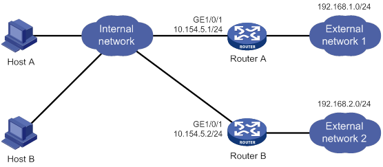
Configuration procedure
1. Configure Router A:
# Specify an IP address for GigabitEthernet 1/0/1.
<RouterA> system-view
[RouterA] interface gigabitethernet 1/0/1
[RouterA-GigabitEthernet1/0/1] ip address 10.154.5.1 24
# Enable IRDP on GigabitEthernet 1/0/1.
[RouterA-GigabitEthernet1/0/1] ip irdp
# Specify preference 1000 for advertised IP addresses on GigabitEthernet 1/0/1.
[RouterA-GigabitEthernet1/0/1] ip irdp preference 1000
# Specify the multicast address 224.0.0.1 as the destination IP address for RAs sent by GigabitEthernet 1/0/1.
[RouterA-GigabitEthernet1/0/1] ip irdp multicast
# Specify the IP address 192.168.1.0 and preference 400 for GigabitEthernet 1/0/1 to proxy-advertise.
[RouterA-GigabitEthernet1/0/1] ip irdp address 192.168.1.0 400
2. Configure Router B:
# Specify an IP address for GigabitEthernet 1/0/1.
<RouterB> system-view
[RouterB] interface gigabitethernet 1/0/1
[RouterB-GigabitEthernet1/0/1] ip address 10.154.5.2 24
# Enable IRDP on GigabitEthernet 1/0/1.
[RouterB-GigabitEthernet1/0/1] ip irdp
# Specify preference 500 for advertised IP addresses on GigabitEthernet 1/0/1.
[RouterB-GigabitEthernet1/0/1] ip irdp preference 500
# Specify the multicast address 224.0.0.1 as the destination IP address for RAs sent by GigabitEthernet 1/0/1.
[RouterB-GigabitEthernet1/0/1] ip irdp multicast
# Specify the IP address 192.168.2.0 and preference 400 for GigabitEthernet 1/0/1 to proxy-advertise.
[RouterB-GigabitEthernet1/0/1] ip irdp address 192.168.2.0 400
Verifying the configuration
# Display the routing table for Host A.
[HostA@localhost ~]$ netstat -rne
Kernel IP routing table
Destination Gateway Genmask Flags Metric Ref Use Iface
10.154.5.0 0.0.0.0 255.255.255.0 U 0 0 0 eth1
192.168.1.0 0.0.0.0 255.255.255.0 U 0 0 0 eth1
192.168.2.0 0.0.0.0 255.255.255.0 U 0 0 0 eth1
0.0.0.0 10.154.5.1 0.0.0.0 UG 0 0 0 eth1
The output shows that the default route on Host A points to IP address 10.154.5.1, and Host A has routes to 192.168.1.0/24 and 192.168.2.0/24.
# Display the routing table for Host B.
[HostB@localhost ~]$ netstat -rne
Kernel IP routing table
Destination Gateway Genmask Flags Metric Ref Use Iface
10.154.5.0 0.0.0.0 255.255.255.0 U 0 0 0 eth1
192.168.1.0 0.0.0.0 255.255.255.0 U 0 0 0 eth1
192.168.2.0 0.0.0.0 255.255.255.0 U 0 0 0 eth1
0.0.0.0 10.154.5.1 0.0.0.0 UG 0 0 0 eth1
The output shows that the default route on Host B points to IP address 10.154.5.1, and Host B has routes to 192.168.1.0/24 and 192.168.2.0/24.
Optimizing IP performance
Command and hardware compatibility
Commands and descriptions for centralized devices apply to the following routers:
· MSR810/810-W/810-W-DB/810-LM/810-W-LM/810-10-PoE/810-LM-HK/810-W-LM-HK/810-LMS/810-LUS.
· MSR2600-6-X1/2600-10-X1.
· MSR 2630.
· MSR3600-28/3600-51.
· MSR3600-28-SI/3600-51-SI.
· MSR3610-X1/3610-X1-DP/3610-X1-DC/3610-X1-DP-DC.
· MSR 3610/3620/3620-DP/3640/3660.
· MSR810-LM-GL/810-W-LM-GL/830-6EI-GL/830-10EI-GL/830-6HI-GL/830-10HI-GL/2600-6-X1-GL/3600-28-SI-GL.
Commands and descriptions for distributed devices apply to the following routers:
· MSR5620.
· MSR 5660.
· MSR 5680.
Enabling an interface to receive and forward directed broadcasts destined for the directly connected network
A directed broadcast packet is destined for all hosts on a specific network. In the destination IP address of the directed broadcast, the network ID identifies the target network, and the host ID is made up of all ones.
If an interface is allowed to forward directed broadcasts destined for the directly connected network, hackers can exploit this vulnerability to attack the target network. In some scenarios, however, an interface must receive and send such directed broadcast packets to support UDP helper and Wake on LAN.
This task enables an interface to accept directed broadcast packets that are destined for and received from the directly connected network to support UDP helper. UDP helper converts the directed broadcasts to unicasts and forwards them to a specific server.
The task also enables the interface to forward directed broadcast packets that are destined for the directly connected network and are received from another subnet to support Wake on LAN. Wake on LAN sends the directed broadcasts to wake up the hosts on the target network.
Configuration procedure
To enable an interface to receive and forward directed broadcasts destined to the directly connected network:
|
Step |
Command |
Remarks |
|
1. Enter system view. |
system-view |
N/A |
|
2. Enter interface view. |
interface interface-type interface-number |
N/A |
|
3. Enable the interface to receive and forward directed broadcasts destined for the directly connected network. |
ip forward-broadcast |
By default, an interface cannot forward directed broadcasts destined for the directly connected network. |
Configuration example
Network requirements
As shown in Figure 80, the default gateway of the host is the IP address 1.1.1.2/24 of the interface GigabitEthernet 1/0/1 of Router A. Configure a static route destined for the host on Router B. Router B can receive directed broadcasts from the host to IP address 2.2.2.255.
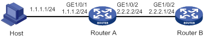
Configuration procedure
1. Configure Router A:
# Specify IP addresses for GigabitEthernet 1/0/1 and GigabitEthernet 1/0/2.
<RouterA> system-view
[RouterA] interface gigabitethernet 1/0/1
[RouterA-GigabitEthernet1/0/1] ip address 1.1.1.2 24
[RouterA-GigabitEthernet1/0/1] quit
[RouterA] interface gigabitethernet 1/0/2
[RouterA-GigabitEthernet1/0/2] ip address 2.2.2.2 24
# Enable GigabitEthernet 1/0/2 to forward directed broadcasts destined for the directly connected network.
[RouterA-GigabitEthernet1/0/2] ip forward-broadcast
2. Configure Router B:
# Configure a static route to the host.
<RouterB> system-view
[RouterB] ip route-static 1.1.1.1 24 2.2.2.2
# Specify an IP address for GigabitEthernet 1/0/2.
[RouterB] interface gigabitethernet 1/0/2
[RouterB-GigabitEthernet1/0/2] ip address 2.2.2.1 24
# Enable GigabitEthernet 1/0/2 to receive directed broadcasts destined for the directly connected network.
[RouterB-GigabitEthernet1/0/2] ip forward-broadcast
After the configurations are completed, if you ping the subnet-directed broadcast address 2.2.2.255 on the host, the interface GigabitEthernet 1/0/2 of Router B can receive the ping packets. If you delete the ip forward-broadcast configuration on any router, the interface GigabitEthernet 1/0/2 of Router B cannot receive the ping packets.
Setting MTU for an interface
When a packet exceeds the MTU of the output interface, the device processes it in one of the following ways:
· If the packet disallows fragmentation, the device discards it.
· If the packet allows fragmentation, the device fragments it and forwards the fragments.
Fragmentation and reassembling consume system resources, so set the appropriate MTU for an interface based on the network environment to avoid fragmentation.
To set the MTU for an interface:
|
Step |
Command |
Remarks |
|
1. Enter system view. |
system-view |
N/A |
|
2. Enter interface view. |
interface interface-type interface-number |
N/A |
|
3. Set the MTU for the interface. |
ip mtu mtu-size |
By default, the MTU is not set. |
Setting TCP MSS for an interface
The maximum segment size (MSS) option informs the receiver of the largest segment that the sender can accept. Each end announces its MSS during TCP connection establishment. If the size of a TCP segment is smaller than the MSS of the receiver, TCP sends the TCP segment without fragmentation. If not, it fragments the segment according to the receiver's MSS.
If you set the TCP MSS on an interface, the size of each TCP segment received or sent on the interface cannot exceed the MSS value.
This configuration takes effect only for TCP connections established after the configuration rather than the TCP connections that already exist.
This configuration is effective only for IP packets. If MPLS is enabled on the interface, do not set the TCP MSS on the interface.
To set the TCP MSS for the interface:
|
Step |
Command |
Remarks |
|
1. Enter system view. |
system-view |
N/A |
|
2. Enter interface view. |
interface interface-type interface-number |
N/A |
|
3. Set the TCP MSS for the interface. |
tcp mss value |
By default, the TCP MSS is not set. |
Configuring TCP path MTU discovery
|
|
IMPORTANT: All devices on a TCP connection must be enabled to send ICMP error messages by using the ip unreachables enable command. |
TCP path MTU discovery (in RFC 1191) discovers the path MTU between the source and destination ends of a TCP connection. It works as follows:
1. A TCP source device sends a packet with the Don't Fragment (DF) bit set.
2. A router discards the packet that exceeds the MTU of the outgoing interface and returns an ICMP error message. The error message contains the MTU of the outgoing interface.
3. Upon receiving the ICMP message, the TCP source device calculates the current path MTU of the TCP connection.
4. The TCP source device sends subsequent TCP segments that each are smaller than the MSS (MSS = path MTU – IP header length – TCP header length).
If the TCP source device still receives ICMP error messages when the MSS is smaller than 32 bytes, the TCP source device will fragment packets.
An ICMP error message received from a router that does not support RFC 1191 has the MTU of the outgoing interface set to 0. Upon receiving the ICMP message, the TCP source device selects the path MTU smaller than the current path MTU from the MTU table as described in RFC 1191. Based on the selected path MTU, the TCP source device calculates the TCP MSS. The MTU table contains MTUs of 68, 296, 508, 1006, 1280, 1492, 2002, 4352, 8166, 17914, 32000, and 65535 bytes. Because the minimum TCP MSS specified by the system is 32 bytes, the actual minimum MTU is 72 bytes.
After you enable TCP path MTU discovery, all new TCP connections will detect the path MTU. The device uses the path MTU to calculate the MSS to avoid IP fragmentation.
The path MTU uses the following aging mechanism to ensure that the source device can increase the path MTU when the minimum link MTU on the path increases:
· When the TCP source device receives an ICMP error message, it reduces the path MTU and starts an aging timer for the path MTU.
· After the aging timer expires, the source device uses a larger MSS in the MTU table, as described in RFC 1191.
· If no ICMP error message is received within two minutes, the source device increases the MSS again until the MSS negotiated during TCP three-way handshake is reached.
To enable TCP path MTU discovery:
|
Step |
Command |
Remarks |
|
1. Enter system view. |
system-view |
N/A |
|
2. Enable TCP path MTU discovery. |
tcp path-mtu-discovery [ aging age-time | no-aging ] |
The default setting is disabled. |
Enabling TCP SYN Cookie
A TCP connection is established through a three-way handshake:
1. The sender sends a SYN packet to the server.
2. The server receives the SYN packet, establishes a TCP semi-connection in SYN_RECEIVED state, and replies with a SYN ACK packet to the sender.
3. The sender receives the SYN ACK packet and replies with an ACK packet. A TCP connection is established.
An attacker can exploit this mechanism to mount SYN Flood attacks. The attacker sends a large number of SYN packets, but does not respond to the SYN ACK packets from the server. As a result, the server establishes a large number of TCP semi-connections and can no longer handle normal services.
SYN Cookie can protect the server from SYN Flood attacks. When the server receives a SYN packet, it responds with a SYN ACK packet without establishing a TCP semi-connection. The server establishes a TCP connection and enters ESTABLISHED state only when it receives an ACK packet from the client.
To enable TCP SYN Cookie:
|
Step |
Command |
Remarks |
|
1. Enter system view. |
system-view |
N/A |
|
2. Enable TCP SYN Cookie. |
tcp syn-cookie enable |
The default setting is disabled. |
Setting the TCP buffer size
|
Step |
Command |
Remarks |
|
1. Enter system view. |
system-view |
N/A |
|
2. Set the size of TCP receive/send buffer. |
tcp window window-size |
The default buffer size is 63 KB. |
Setting TCP timers
You can set the following TCP timers:
· SYN wait timer—TCP starts the SYN wait timer after sending a SYN packet. Within the SYN wait timer if no response is received or the upper limit on TCP connection tries is reached, TCP fails to establish the connection.
· FIN wait timer—TCP starts the FIN wait timer when TCP changes the connection state to FIN_WAIT_2. If no FIN packet is received within the timer interval, TCP terminates the connection. If a FIN packet is received, TCP changes the connection state to TIME_WAIT. If a non-FIN packet is received, TCP restarts the timer, and tears down the connection when the timer expires.
To set TCP timers:
|
Step |
Command |
Remarks |
|
1. Enter system view. |
system-view |
N/A |
|
2. Set TCP timers. |
·
Set the TCP SYN wait timer: ·
Set the TCP FIN wait timer: |
By default: · The TCP SYN wait timer is 75 seconds. · The TCP FIN wait timer is 675 seconds. |
Enabling sending ICMP error messages
Perform this task to enable sending ICMP error messages, including redirect, time exceeded, and destination unreachable messages.
· ICMP redirect messages
A host that has only one default route sends all packets to the default gateway. The default gateway sends an ICMP redirect message to inform the host of a correct next hop by following these rules:
? The receiving and sending interfaces are the same.
? The selected route is not created or modified by any ICMP redirect messages.
? The selected route is not destined for 0.0.0.0.
? There is no source route option in the received packet.
ICMP redirect messages simplify host management and enable hosts to gradually optimize their routing table.
· ICMP time exceeded messages
A device sends ICMP time exceeded messages by following these rules:
? The device sends the source an ICMP TTL exceeded in transit message when the following conditions are met:
- The received packet is not destined for the device.
- The TTL field of the packet is 1.
? When the device receives the first fragment of an IP datagram destined for it, it starts a timer. If the timer expires before all the fragments of the datagram are received, the device sends an ICMP fragment reassembly time exceeded message to the source.
· ICMP destination unreachable messages
A device sends ICMP destination unreachable messages by following these rules:
? The device sends the source an ICMP network unreachable message when the following conditions are met:
- The packet does not match any route.
- No default route exists in the routing table.
? The device sends the source an ICMP protocol unreachable message when the following conditions are met:
- The packet is destined for the device.
- The transport layer protocol of the packet is not supported by the device.
|
|
NOTE: If a DHCP enabled device receives an ICMP echo reply without sending any ICMP echo requests, the device does not send any ICMP protocol unreachable messages to the source. For more information about DHCP, see Layer 3—IP Services Configuration Guide. |
? The device sends the source an ICMP port unreachable message when the following conditions are met:
- The UDP packet is destined for the device.
- The packet's port number does not match the corresponding process.
? The device sends the source an ICMP source route failed message when the following conditions are met:
- The source uses Strict Source Routing to send packets.
- The intermediate device finds that the next hop specified by the source is not directly connected.
? The device sends the source an ICMP fragmentation needed and DF set message when the following conditions are met:
- The MTU of the sending interface is smaller than the packet.
- The packet has DF set.
To enable sending ICMP error messages:
|
Step |
Command |
Remarks |
|
1. Enter system view. |
system-view |
N/A |
|
2. Enable sending ICMP error messages. |
·
Enable sending ICMP redirect messages: ·
Enable sending ICMP time exceeded
messages: ·
Enable sending ICMP destination
unreachable messages: |
The default settings are disabled. |
Sending ICMP error messages facilitates network management, but sending excessive ICMP messages increases network traffic. The device performance degrades if it receives a lot of malicious ICMP messages that cause it to respond with ICMP error messages.
To prevent such problems, you can disable the device from sending ICMP error messages. A device that is disabled from sending ICMP time exceeded messages does not send ICMP TTL exceeded in transit messages. However, it can still send ICMP fragment reassembly time exceeded messages.
Configuring rate limit for ICMP error messages
To avoid sending excessive ICMP error messages within a short period that might cause network congestion, you can limit the rate at which ICMP error messages are sent. A token bucket algorithm is used with one token representing one ICMP error message.
A token is placed in the bucket at intervals until the maximum number of tokens that the bucket can hold is reached.
A token is removed from the bucket when an ICMP error message is sent. When the bucket is empty, ICMP error messages are not sent until a new token is placed in the bucket.
To configure rate limit for ICMP error messages:
|
Step |
Command |
Remarks |
|
1. Enter system view. |
system-view |
N/A |
|
2. Set the bucket size and the interval for tokens to arrive in the bucket for ICMP error messages. |
ip icmp error-interval interval [ bucketsize ] |
By default, the bucket allows a maximum of 10 tokens. A token is placed in the bucket at an interval of 100 milliseconds. To disable the ICMP rate limit, set the interval to 0 milliseconds. |
Specifying the source address for ICMP packets
Perform this task to specify the source IP address for outgoing ping echo request and ICMP error messages. As a best practice, specify the IP address of the loopback interface as the source IP address. This feature helps users to locate the sending device easily.
If you specify an IP address in the ping command, ping echo requests use the specified address as the source IP address rather than the IP address specified by the ip icmp source command.
To specify the source IP address for ICMP packets:
|
Step |
Command |
Remarks |
|
1. Enter system view. |
system-view |
N/A |
|
2. Specify the source address for outgoing ICMP packets. |
ip icmp source [ vpn-instance vpn-instance-name ] ip-address |
By default, the device uses the IP address of the sending interface as the source IP address for outgoing ICMP packets. |
Enabling IPv4 local fragment reassembly
This feature improves IPv4 fragment reassembly efficiency on distributed devices as follows:
· In standalone mode, this feature enables the receiving LPU to reassemble the fragments of an IPv4 packet if all the fragments arrive at it. If this feature is disabled, all fragments are delivered to the active MPU for reassembly. The feature applies only to fragments destined for the same LPU.
· In IRF mode, this feature enables the receiving subordinate to reassemble the fragments of an IPv4 packet if all fragments arrive at it. If this feature is disabled, all fragments are delivered to the master device for reassembly. The feature applies only to fragments destined for the same subordinate.
To enable IPv4 local fragment reassembly:
|
Step |
Command |
Remarks |
|
1. Enter system view. |
N/A |
|
|
2. Enable IPv4 local fragment reassembly. |
By default, IPv4 local fragment reassembly is disabled. |
Displaying and maintaining IP performance optimization
Execute display commands in any view and reset commands in user view.
|
Task |
Command |
|
Display brief information about RawIP connections (centralized devices in standalone mode). |
display rawip |
|
Display brief information about RawIP connections (distributed devices in standalone mode/centralized devices in IRF mode). |
display rawip [ slot slot-number ] |
|
Display brief information about RawIP connections (distributed devices in IRF mode). |
display rawip [ chassis chassis-number slot slot-number ] |
|
Display detailed information about RawIP connections (centralized devices in standalone mode). |
display rawip verbose [ pcb pcb-index ] |
|
Display detailed information about RawIP connections (distributed devices in standalone mode/centralized devices in IRF mode). |
display rawip verbose [ slot slot-number [ pcb pcb-index ] ] |
|
Display detailed information about RawIP connections (distributed devices in IRF mode). |
display rawip verbose [ chassis chassis-number slot slot-number [ pcb pcb-index ] ] |
|
Display brief information about TCP connections (centralized devices in standalone mode). |
display tcp |
|
Display brief information about TCP connections (distributed devices in standalone mode/centralized devices in IRF mode). |
display tcp [ slot slot-number ] |
|
Display brief information about TCP connections (distributed devices in IRF mode). |
display tcp [ chassis chassis-number slot slot-number ] |
|
Display brief information about TCP proxy (centralized devices in standalone mode). |
|
|
Display brief information about TCP proxy (distributed devices in standalone mode/centralized devices in IRF mode). |
|
|
Display brief information about TCP proxy (distributed devices in IRF mode). |
|
|
Display the usage of non-well known ports for TCP proxy. (centralized devices in standalone mode). |
display tcp-proxy port-info |
|
Display the usage of non-well known ports for TCP proxy. (distributed devices in standalone mode/centralized devices in IRF mode). |
display tcp-proxy port-info slot slot-number |
|
Display the usage of non-well known ports for TCP proxy. (distributed devices in IRF mode). |
display tcp-proxy port-info chassis chassis-number slot slot-number |
|
Display detailed information about TCP connections (centralized devices in standalone mode). |
display tcp verbose [ pcb pcb-index ] |
|
Display detailed information about TCP connections (distributed devices in standalone mode/centralized devices in IRF mode). |
display tcp verbose [ slot slot-number [ pcb pcb-index ] ] |
|
Display detailed information about TCP connections (distributed devices in IRF mode). |
display tcp verbose [ chassis chassis-number slot slot-number [ pcb pcb-index ] ] |
|
Display brief information about UDP connections (centralized devices in standalone mode). |
display udp |
|
Display brief information about UDP connections (distributed devices in standalone mode/centralized devices in IRF mode). |
display udp [ slot slot-number ] |
|
Display brief information about UDP connections (distributed devices in IRF mode). |
display udp [ chassis chassis-number slot slot-number ] |
|
Display detailed information about UDP connections (centralized devices in standalone mode). |
display udp verbose [ pcb pcb-index ] |
|
Display detailed information about UDP connections (distributed devices in standalone mode/centralized devices in IRF mode). |
display udp verbose [ slot slot-number [ pcb pcb-index ] ] |
|
Display detailed information about UDP connections (distributed devices in IRF mode). |
display udp verbose [ chassis chassis-number slot slot-number [ pcb pcb-index ] ] |
|
Display IP packet statistics (centralized devices in standalone mode). |
display ip statistics |
|
Display IP packet statistics (distributed devices in standalone mode/centralized devices in IRF mode). |
display ip statistics [ slot slot-number ] |
|
Display IP packet statistics (distributed devices in IRF mode). |
display ip statistics [ chassis chassis-number slot slot-number ] |
|
Display TCP traffic statistics (centralized devices in standalone mode). |
display tcp statistics |
|
Display TCP traffic statistics (distributed devices in standalone mode/centralized devices in IRF mode). |
display tcp statistics [ slot slot-number ] |
|
Display TCP traffic statistics (distributed devices in IRF mode). |
display tcp statistics [ chassis chassis-number slot slot-number ] |
|
Display UDP traffic statistics (centralized devices in standalone mode). |
display udp statistics |
|
Display UDP traffic statistics (distributed devices in standalone mode/centralized devices in IRF mode). |
display udp statistics [ slot slot-number ] |
|
Display UDP traffic statistics (distributed devices in IRF mode). |
display udp statistics [ chassis chassis-number slot slot-number ] |
|
Display ICMP statistics (centralized devices in standalone mode). |
display icmp statistics |
|
Display ICMP statistics (distributed devices in standalone mode/centralized devices in IRF mode). |
display icmp statistics [ slot slot-number ] |
|
Display ICMP statistics (distributed devices in IRF mode). |
display icmp statistics [ chassis chassis-number slot slot-number ] |
|
Clear IP packet statistics (centralized devices in standalone mode). |
reset ip statistics |
|
Clear IP packet statistics (distributed devices in standalone mode/centralized devices in IRF mode). |
reset ip statistics [ slot slot-number ] |
|
Clear IP packet statistics (distributed devices in IRF mode). |
reset ip statistics [ chassis chassis-number slot slot-number ] |
|
Clear TCP traffic statistics. |
reset tcp statistics |
|
Clear UDP traffic statistics. |
reset udp statistics |
Configuring UDP helper
Overview
UDP helper can provide the following packet conversion for packets with specific UDP destination port numbers:
· Convert broadcast to unicast, and forward the unicast packets to specific destinations.
· Convert broadcast to multicast, and forward the multicast packets.
· Convert multicast to broadcast or unicast, and forward the broadcast or unicast packets.
Feature and hardware compatibility
|
Hardware |
UDP helper compatibility |
|
MSR810/810-W/810-W-DB/810-LM/810-W-LM/810-10-PoE /810-LM-HK/MSR810-W-LM-HK |
Yes |
|
MSR810-LMS/810-LUS |
No |
|
MSR2600-6-X1/2600-10-X1 |
Yes |
|
MSR 2630 |
Yes |
|
MSR3600-28/3600-51 |
Yes |
|
MSR3600-28-SI/3600-51-SI |
No |
|
MSR3610-X1/3610-X1-DP/3610-X1-DC/3610-X1-DP-DC |
Yes |
|
MSR 3610/3620/3620-DP/3640/3660 |
Yes |
|
MSR 5620/5660/5680 |
Yes |
|
Hardware |
UDP helper compatibility |
|
MSR810-LM-GL |
Yes |
|
MSR810-W-LM-GL |
Yes |
|
MSR830-6EI-GL |
Yes |
|
MSR830-10EI-GL |
Yes |
|
MSR830-6HI-GL |
Yes |
|
MSR830-10HI-GL |
Yes |
|
MSR2600-6-X1-GL |
Yes |
|
MSR3600-28-SI-GL |
Yes |
Configuration restrictions and guidelines
When you configure UDP helper, follow these restrictions and guidelines:
· By default, an interface on the device does not receive directed broadcasts destined for the directly connected network. To use UDP helper, execute the ip forward-broadcast command. For more information about receiving directed broadcasts destined for the directly connected network, see "Optimizing IP performance."
· Do not set UDP ports 67 and 68 for UDP helper, because UDP helper cannot forward DHCP broadcast packets.
· You can specify a maximum of 256 UDP ports for UDP helper.
· You can specify a maximum of 20 unicast and multicast addresses for UDP helper to convert broadcast packets on an interface.
· You can map one multicast address to a maximum of 16 broadcast and unicast addresses for UDP helper to convert multicast packets on an interface.
Configuring UDP helper to convert broadcast to unicast
You can configure UDP helper to convert broadcast packets with specific UDP port numbers to unicast packets.
Upon receiving a UDP broadcast packet, UDP helper uses the configured UDP ports to match the UDP destination port number of the packet.
· If a match is found, UDP helper duplicates the packet and modifies the destination IP address of the copy to the configured unicast address. Then UDP helper forwards the unicast packet to the unicast address.
· If no match is found, UDP helper does not process the packet.
To configure UDP helper to convert broadcast to unicast:
|
Step |
Command |
Remarks |
|
1. Enter system view. |
system-view |
N/A |
|
2. Enable UDP helper. |
udp-helper enable |
By default, UDP helper is disabled. |
|
3. Specify a UDP port number. |
udp-helper port { port-number | dns | netbios-ds | netbios-ns | tacacs | tftp | time } |
By default, no UDP port numbers are specified. |
|
4. Enter interface view. |
interface interface-type interface-number |
N/A |
|
5. Specify a destination server for UDP helper to convert broadcast to unicast. |
udp-helper server ip-address [ global | vpn-instance vpn-instance-name ] |
By default, no destination server is specified. If you specify multiple destination servers, UDP helper creates one copy for each server. Use this command on the interface that receives broadcast packets. |
Configuring UDP helper to convert broadcast to multicast
You can configure UDP helper to convert broadcast packets with specific UDP port numbers to multicast packets.
Upon receiving a UDP broadcast packet, UDP helper uses the configured UDP ports to match the UDP destination port number of the packet.
· If a match is found, UDP helper duplicates the packet and modifies the destination IP address of the copy to the configured multicast address. Then UDP helper forwards the packet to the multicast group.
· If no match is found, UDP helper does not process the packet.
To configure UDP helper to convert broadcast to multicast:
|
Step |
Command |
Remarks |
|
1. Enter system view. |
system-view |
N/A |
|
2. Enable UDP helper. |
udp-helper enable |
By default, UDP helper is disabled. |
|
3. Specify a UDP port number. |
udp-helper port { port-number | dns | netbios-ds | netbios-ns | tacacs | tftp | time } |
By default, no UDP port numbers are specified. |
|
4. Enter interface view. |
interface interface-type interface-number |
N/A |
|
5. Specify a destination multicast address for UDP helper to convert broadcast to multicast. |
udp-helper broadcast-map multicast-address [ acl acl-number ] |
By default, no destination multicast address is specified for UDP helper. If you specify multiple multicast addresses, UDP helper creates one copy for each address. Use this command on the interface that receives broadcast packets. |
Configuring UDP helper to convert multicast to broadcast or unicast
You can configure UDP helper to convert multicast packets with specific UDP port numbers and multicast addresses to broadcast or unicast packets.
Upon receiving a UDP multicast packet, UDP helper uses the configured UDP ports to match the UDP destination port number of the packet.
· If a match is found, UDP helper searches the configured mappings based on the packet's destination multicast address.
? UDP helper duplicates the packet and modifies the copy's destination IP address to the broadcast or unicast address in the matched mapping. Then UDP helper forwards the packet to its destination.
? If no match is found, UDP helper does not process the packet.
· If the packet's destination port number does not match the configured UDP ports, UDP helper does not process the packet.
To configure UDP helper to convert multicast to broadcast or unicast:
|
Step |
Command |
Remarks |
|
1. Enter system view. |
system-view |
N/A |
|
2. Enable UDP helper. |
udp-helper enable |
By default, UDP helper is disabled. |
|
3. Specify a UDP port number. |
udp-helper port { port-number | dns | netbios-ds | netbios-ns | tacacs | tftp | time } |
By default, no UDP port numbers are specified. |
|
4. Enter interface view. |
interface interface-type interface-number |
N/A |
|
5. Map a multicast address to a directed broadcast or a unicast address for UDP helper. |
udp-helper multicast-map multicast-address ip-address [ global | vpn-instance vpn-instance-name ] [ acl acl-number ] |
By default, no address mapping is specified for UDP helper. If you specify multiple multicast and unicast addresses, UDP helper creates one copy for each address. For multicast to broadcast conversion, do not specify a limited broadcast address for the ip-address argument. Use this command on the interface that receives multicast packets. |
Displaying and maintaining UDP helper
Execute display command in any view and reset commands in user view.
|
Task |
Command |
|
Display information about broadcast to unicast conversion by UDP helper on an interface. |
display udp-helper interface interface-type interface-number |
|
Clear packet statistics for UDP helper. |
reset udp-helper statistics |
UDP helper configuration examples
Configuring UDP helper to convert broadcast to unicast
Network requirements
As shown in Figure 81, configure UDP helper to convert broadcast to unicast on GigabitEthernet 1/0/1 of Router A. This feature enables Router A to forward broadcast packets with UDP destination port 55 to the destination server 10.2.1.1/16.
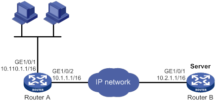
Configuration procedure
Make sure Router A can reach the subnet 10.2.0.0/16.
# Enable UDP helper.
<RouterA> system-view
[RouterA] udp-helper enable
# Specify the UDP port 55 for UDP helper.
[RouterA] udp-helper port 55
# Specify the destination server 10.2.1.1 for UDP helper to convert broadcast to unicast on GigabitEthernet 1/0/1.
[RouterA] interface gigabitethernet 1/0/1
[RouterA-GigabitEthernet1/0/1] ip address 10.110.1.1 16
[RouterA-GigabitEthernet1/0/1] udp-helper server 10.2.1.1
Verifying the configuration
# Display information about broadcast to unicast conversion by UDP helper on GigabitEthernet 1/0/1.
[RouterA-GigabitEthernet1/0/1] display udp-helper interface gigabitethernet 1/0/1
Interface Server VPN instance Server address Packets sent
GigabitEthernet1/0/1 N/A 10.2.1.1 5
Configuring UDP helper to convert broadcast to multicast
Network requirements
As shown in Figure 82, Router B can receive multicast packets destined for 225.1.1.1.
Configure UDP helper to convert broadcast to multicast on GigabitEthernet 1/0/1 of Router A. This feature enables Router A to forward broadcast packets with UDP destination port number 55 to the multicast group 225.1.1.1.
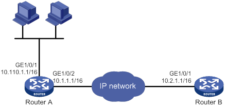
Configuration procedure
Make sure Router A can reach the subnet 10.2.0.0/16.
# Enable UDP helper.
<RouterA> system-view
[RouterA] udp-helper enable
# Enable the UDP port 55 for UDP helper.
[RouterA] udp-helper port 55
# Configure UDP helper to convert broadcast packets to multicast packets destined for 225.1.1.1 on GigabitEthernet 1/0/1.
[RouterA] interface gigabitethernet 1/0/1
[RouterA-GigabitEthernet1/0/1] ip address 10.110.1.1 16
[RouterA-GigabitEthernet1/0/1] udp-helper broadcast-map 225.1.1.1
[RouterA-GigabitEthernet1/0/1] quit
# Enable IP multicast routing globally.
[RouterA] multicast routing
[RouterA-mrib] quit
# Enable PIM-DIM and IGMP on GigabitEthernet 1/0/1.
[RouterA] interface gigabitethernet 1/0/1
[RouterA-GigabitEthernet1/0/1] pim dm
[RouterA-GigabitEthernet1/0/1] igmp enable
# Configure GigabitEthernet 1/0/1 as a static member of the multicast group 225.1.1.1.
[RouterA-GigabitEthernet1/0/1] igmp static-group 225.1.1.1
# Enable PIM-DIM and IGMP on GigabitEthernet 1/0/2.
[RouterA-GigabitEthernet1/0/2] pim dm
[RouterA-GigabitEthernet1/0/2] igmp enable
# Configure GigabitEthernet 1/0/2 as a static member of the multicast group 225.1.1.1.
[RouterA-GigabitEthernet1/0/2] igmp static-group 225.1.1.1
Verifying the configuration
Verify that you can capture multicast packets from Router A on Router B.
Configuring UDP helper to convert multicast to broadcast
Network requirements
As shown in Figure 83, GigabitEthernet 1/0/1 of Router B is a member of the multicast group 225.1.1.1.
Configure UDP helper to convert multicast to broadcast on GigabitEthernet 1/0/1 of Router A. This feature enables Router A to forward multicast packets from Router B to all hosts on 10.110.0.0/16. The multicast packets have the following details:
· UDP destination port number 55.
· Destination IP address 225.1.1.1.
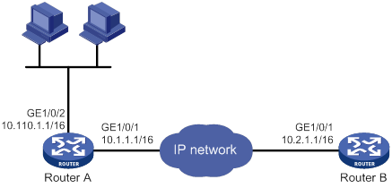
Configuration procedure
Make sure Router A can reach the subnet 10.2.0.0/16.
# Enable UDP helper.
<RouterA> system-view
[RouterA] udp-helper enable
# Enable the UDP port 55 for UDP helper.
[RouterA] udp-helper port 55
# Configure UDP helper to convert multicast packets destined for 225.1.1.1 to broadcast packets destined for 10.110.255.255.
[RouterA] interface gigabitethernet 1/0/1
[RouterA-GigabitEthernet1/0/1] udp-helper multicast-map 225.1.1.1 10.110.255.255
Verifying the configuration
Verify that you can capture broadcast packets on all hosts on the network segment 10.110.0.0/16. The broadcast packets are from Router A.
Configuring basic IPv6 settings
Overview
IPv6, also called IP next generation (IPng), was designed by the IETF as the successor to IPv4. One significant difference between IPv6 and IPv4 is that IPv6 increases the IP address size from 32 bits to 128 bits.
IPv6 features
Simplified header format
IPv6 removes several IPv4 header fields or moves them to the IPv6 extension headers to reduce the length of the basic IPv6 packet header. The basic IPv6 packet header has a fixed length of 40 bytes to simplify IPv6 packet handling and improve forwarding efficiency. Although the IPv6 address size is four times the IPv4 address size, the basic IPv6 packet header size is only twice the size of the option-less IPv4 packet header.
Figure 84 IPv4 packet header format and basic IPv6 packet header format
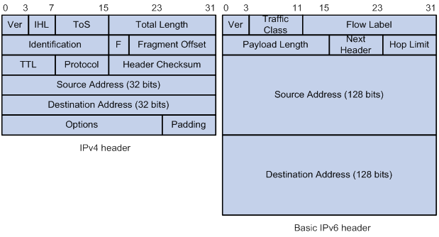
Larger address space
IPv6 can provide 3.4 x 1038 addresses to meet the requirements of hierarchical address assignment for both public and private networks.
Hierarchical address structure
IPv6 uses a hierarchical address structure to speed up route lookup and reduce the IPv6 routing table size through route aggregation.
Address autoconfiguration
To simplify host configuration, IPv6 supports stateful and stateless address autoconfiguration.
· Stateful address autoconfiguration enables a host to acquire an IPv6 address and other configuration information from a server (for example, a DHCPv6 server). For more information about DHCPv6 server, see "Configuring the DHCPv6 server."
· Stateless address autoconfiguration enables a host to automatically generate an IPv6 address and other configuration information by using its link-layer address and the prefix information advertised by a router.
To communicate with other hosts on the same link, a host automatically generates a link-local address based on its link-layer address and the link-local address prefix (FE80::/10).
Built-in security
IPv6 defines extension headers to support IPsec. IPsec provides end-to-end security and enhances interoperability among different IPv6 applications.
QoS support
The Flow Label field in the IPv6 header allows the device to label the packets of a specific flow for special handling.
Enhanced neighbor discovery mechanism
The IPv6 neighbor discovery protocol uses a group of ICMPv6 messages to manage information exchange among neighboring nodes on the same link. The group of ICMPv6 messages replaces ARP messages, ICMPv4 router discovery messages, and ICMPv4 redirect messages and provides a series of other functions.
Flexible extension headers
IPv6 eliminates the Options field in the header and introduces optional extension headers to provide scalability and improve efficiency. The Options field in the IPv4 packet header contains a maximum of 40 bytes, whereas the IPv6 extension headers are restricted to the maximum size of IPv6 packets.
IPv6 addresses
IPv6 address formats
An IPv6 address is represented as a set of 16-bit hexadecimals separated by colons (:). An IPv6 address is divided into eight groups, and each 16-bit group is represented by four hexadecimal numbers, for example, 2001:0000:130F:0000:0000:09C0:876A:130B.
To simplify the representation of IPv6 addresses, you can handle zeros in IPv6 addresses by using the following methods:
· The leading zeros in each group can be removed. For example, the above address can be represented in a shorter format as 2001:0:130F:0:0:9C0:876A:130B.
· If an IPv6 address contains one or more consecutive groups of zeros, they can be replaced by a double colon (::). For example, the above address can be represented in the shortest format as 2001:0:130F::9C0:876A:130B.
|
|
IMPORTANT: A double colon can appear once or not at all in an IPv6 address. This limit allows the device to determine how many zeros the double colon represents and correctly convert it to zeros to restore a 128-bit IPv6 address. |
An IPv6 address consists of an address prefix and an interface ID, which are equivalent to the network ID and the host ID of an IPv4 address.
An IPv6 address prefix is written in IPv6-address/prefix-length notation. The prefix-length is a decimal number indicating how many leftmost bits of the IPv6 address are in the address prefix.
IPv6 address types
IPv6 addresses include the following types:
· Unicast address—An identifier for a single interface, similar to an IPv4 unicast address. A packet sent to a unicast address is delivered to the interface identified by that address.
· Multicast address—An identifier for a set of interfaces (typically belonging to different nodes), similar to an IPv4 multicast address. A packet sent to a multicast address is delivered to all interfaces identified by that address.
Broadcast addresses are replaced by multicast addresses in IPv6.
· Anycast address—An identifier for a set of interfaces (typically belonging to different nodes). A packet sent to an anycast address is delivered to the nearest interface among the interfaces identified by that address. The nearest interface is chosen according to the routing protocol's measure of distance.
The type of an IPv6 address is designated by the first several bits, called the format prefix.
Table 7 Mappings between address types and format prefixes
|
Type |
Format prefix (binary) |
IPv6 prefix ID |
|
|
Unicast address |
Unspecified address |
00...0 (128 bits) |
::/128 |
|
Loopback address |
00...1 (128 bits) |
::1/128 |
|
|
Link-local address |
1111111010 |
FE80::/10 |
|
|
Global unicast address |
Other forms |
N/A |
|
|
Multicast address |
11111111 |
FF00::/8 |
|
|
Anycast address |
Anycast addresses use the unicast address space and have the identical structure of unicast addresses. |
||
Unicast addresses
Unicast addresses include global unicast addresses, link-local unicast addresses, the loopback address, and the unspecified address.
· Global unicast addresses—Equivalent to public IPv4 addresses, global unicast addresses are provided for Internet service providers. This type of address allows for prefix aggregation to restrict the number of global routing entries.
· Link-local addresses—Used for communication among link-local nodes for neighbor discovery and stateless autoconfiguration. Packets with link-local source or destination addresses are not forwarded to other links.
· A loopback address—0:0:0:0:0:0:0:1 (or ::1). It has the same function as the loopback address in IPv4. It cannot be assigned to any physical interface. A node uses this address to send an IPv6 packet to itself.
· An unspecified address—0:0:0:0:0:0:0:0 (or ::). It cannot be assigned to any node. Before acquiring a valid IPv6 address, a node fills this address in the source address field of IPv6 packets. The unspecified address cannot be used as a destination IPv6 address.
Multicast addresses
IPv6 multicast addresses listed in Table 8 are reserved for special purposes.
Table 8 Reserved IPv6 multicast addresses
|
Address |
Application |
|
FF01::1 |
Node-local scope all-nodes multicast address. |
|
FF02::1 |
Link-local scope all-nodes multicast address. |
|
FF01::2 |
Node-local scope all-routers multicast address. |
|
FF02::2 |
Link-local scope all-routers multicast address. |
Multicast addresses also include solicited-node addresses. A node uses a solicited-node multicast address to acquire the link-layer address of a neighboring node on the same link and to detect duplicate addresses. Each IPv6 unicast or anycast address has a corresponding solicited-node address. The format of a solicited-node multicast address is FF02:0:0:0:0:1:FFXX:XXXX. FF02:0:0:0:0:1:FF is fixed and consists of 104 bits, and XX:XXXX is the last 24 bits of an IPv6 unicast address or anycast address.
EUI-64 address-based interface identifiers
An interface identifier is 64-bit long and uniquely identifies an interface on a link. Interfaces generate EUI-64 address-based interface identifiers differently.
· On an IEEE 802 interface (such as an Ethernet interface and a VLAN interface)—The interface identifier is derived from the link-layer address (typically a MAC address) of the interface. The MAC address is 48-bit long.
To obtain an EUI-64 address-based interface identifier, follow these steps:
a. Insert the 16-bit binary number 1111111111111110 (hexadecimal value of FFFE) behind the 24th high-order bit of the MAC address.
b. Invert the universal/local (U/L) bit (the seventh high-order bit). This operation makes the interface identifier have the same local or global significance as the MAC address.
Figure 85 Converting a MAC address into an EUI-64 address-based interface identifier
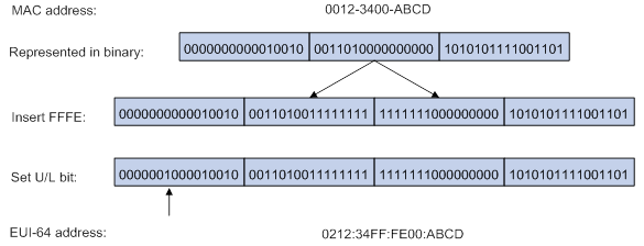
· On a tunnel interface—The lower 32 bits of the EUI-64 address-based interface identifier are the source IPv4 address of the tunnel interface. The higher 32 bits of the EUI-64 address-based interface identifier of an ISATAP tunnel interface are 0000:5EFE, whereas those of other tunnel interfaces are all zeros. For more information about tunnels, see "Configuring tunneling."
· On an interface of another type (such as a serial interface)—The EUI-64 address-based interface identifier is generated randomly by the device.
IPv6 ND protocol
The IPv6 Neighbor Discovery (ND) protocol uses the following ICMPv6 messages:
Table 9 ICMPv6 messages used by ND
|
ICMPv6 message |
Type |
Function |
|
Neighbor Solicitation (NS) |
135 |
Acquires the link-layer address of a neighbor. |
|
Verifies whether a neighbor is reachable. |
||
|
Detects duplicate addresses. |
||
|
Neighbor Advertisement (NA) |
136 |
Responds to an NS message. |
|
Notifies the neighboring nodes of link layer changes. |
||
|
Router Solicitation (RS) |
133 |
Requests an address prefix and other configuration information for autoconfiguration after startup. |
|
Router Advertisement (RA) |
134 |
Responds to an RS message. |
|
Advertises information, such as the Prefix Information options and flag bits. |
||
|
Redirect |
137 |
Informs the source host of a better next hop on the path to a particular destination when certain conditions are met. |
Address resolution
This function is similar to ARP in IPv4. An IPv6 node acquires the link-layer addresses of neighboring nodes on the same link through NS and NA messages. Figure 86 shows how Host A acquires the link-layer address of Host B on the same link.
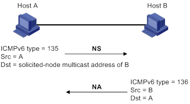
The address resolution procedure is as follows:
1. Host A multicasts an NS message. The source address of the NS message is the IPv6 address of the sending interface of Host A. The destination address is the solicited-node multicast address of Host B. The NS message body contains the link-layer address of Host A and the target IPv6 address.
2. After receiving the NS message, Host B determines whether the target address of the packet is its IPv6 address. If it is, Host B learns the link-layer address of Host A, and then unicasts an NA message containing its link-layer address.
3. Host A acquires the link-layer address of Host B from the NA message.
Neighbor reachability detection
After Host A acquires the link-layer address of its neighbor Host B, Host A can use NS and NA messages to test reachability of Host B as follows:
1. Host A sends an NS message whose destination address is the IPv6 address of Host B.
2. If Host A receives an NA message from Host B, Host A decides that Host B is reachable. Otherwise, Host B is unreachable.
Duplicate address detection
After Host A acquires an IPv6 address, it performs Duplicate Address Detection (DAD) to check whether the address is being used by any other node. This is similar to gratuitous ARP in IPv4. DAD is accomplished through NS and NA messages.
Figure 87 Duplicate address detection
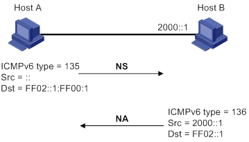
1. Host A sends an NS message. The source address is the unspecified address and the destination address is the corresponding solicited-node multicast address of the IPv6 address to be detected. The NS message body contains the detected IPv6 address.
2. If Host B uses this IPv6 address, Host B returns an NA message that contains its IPv6 address.
3. Host A knows that the IPv6 address is being used by Host B after receiving the NA message from Host B. If receiving no NA message, Host A decides that the IPv6 address is not in use and uses this address.
Router/prefix discovery and stateless address autoconfiguration
A node performs router/prefix discovery and stateless address autoconfiguration as follows:
1. At startup, a node sends an RS message to request configuration information from a router.
2. The router returns an RA message containing the Prefix Information option and other configuration information. (The router also periodically sends an RA message.)
The generated IPv6 address is valid within the valid lifetime and becomes invalid when the valid lifetime expires.
After the preferred lifetime expires, the node cannot use the generated IPv6 address to establish new connections, but can receive packets destined for the IPv6 address. The preferred lifetime cannot be greater than the valid lifetime.
Redirection
Upon receiving a packet from a host, the gateway sends an ICMPv6 redirect message to inform the host of a better next hop when the following conditions are met:
· The interface receiving the packet is the same as the interface forwarding the packet.
· The selected route is not created or modified by an ICMPv6 redirect message.
· The selected route is not a default route on the device.
· The forwarded IPv6 packet does not contain the routing extension header.
IPv6 path MTU discovery
The links that a packet passes from a source to a destination can have different MTUs, among which the minimum MTU is the path MTU. If a packet exceeds the path MTU, the source end fragments the packet to reduce the processing pressure on intermediate devices and to use network resources effectively.
A source end uses path MTU discovery to find the path MTU to a destination, as shown in Figure 88.
Figure 88 Path MTU discovery process
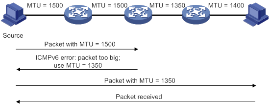
1. The source host sends a packet no larger than its MTU to the destination host.
2. If the MTU of a device's output interface is smaller than the packet, the device performs the following operations:
? Discards the packet.
? Returns an ICMPv6 error message containing the interface MTU to the source host.
3. Upon receiving the ICMPv6 error message, the source host performs the following operations:
? Uses the returned MTU to limit the packet size.
? Performs fragmentation.
? Sends the fragments to the destination host.
4. Step 2 and step 3 are repeated until the destination host receives the packet. In this way, the source host finds the minimum MTU of all links in the path to the destination host.
IPv6 transition technologies
IPv6 transition technologies enable communication between IPv4 and IPv6 networks. The following IPv6 transition technologies can be used for different applications:
· Dual stack (RFC 2893)
· Tunneling (RFC 2893)
· NAT-PT (RFC 2766)
· IPv6 on the provider edge routers (6PE)
Dual stack
Dual stack is the most direct transition approach. A network node that supports both IPv4 and IPv6 is a dual-stack node. A dual-stack node configured with an IPv4 address and an IPv6 address can forward both IPv4 and IPv6 packets. An application that supports both IPv4 and IPv6 prefers IPv6 at the network layer.
Dual stack is suitable for communication between IPv4 nodes or between IPv6 nodes. It is the basis of all transition technologies. However, it does not solve the IPv4 address depletion issue because each dual-stack node must have a globally unique IPv4 address.
Tunneling
Tunneling uses one network protocol to encapsulate the packets of another network protocol and transfers them over the network. For more information about tunneling, see "Configuring tunneling."
NAT-PT
Network Address Translation – Protocol Translation (NAT-PT) enables communication between IPv4 and IPv6 nodes by translating between IPv4 and IPv6 packets. It performs IP address translation, and according to different protocols, performs semantic translation for packets. This technology is only suitable for communication between a pure IPv4 node and a pure IPv6 node.
6PE
6PE enables communication between isolated IPv6 networks over an IPv4 backbone network.
6PE adds labels to the IPv6 routing information about customer networks and advertises the information into the IPv4 backbone network over internal Border Gateway Protocol (IBGP) sessions. IPv6 packets are labeled and forwarded over tunnels on the backbone network. The tunnels can be GRE tunnels or MPLS LSPs.
Figure 89 Network diagram
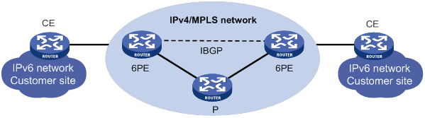
6PE is a highly efficient solution. When an ISP wants to utilize the existing IPv4/MPLS network to provide IPv6 traffic switching, it only needs to upgrade the PE routers. In addition, the operation risk of 6PE is very low. For more information about 6PE, see Layer 3—IP Routing Configuration Guide.
Compatibility information
Feature and hardware compatibility
IPv6-related features are not supported on the following routers:
· MSR810/810-W/810-W-DB/810-LM/810-W-LM/810-10-PoE/810-LM-HK/810-W-LM-HK/810-LMS/810-LUS.
· MSR3600-28-SI/3600-51-SI.
Command and hardware compatibility
Commands and descriptions for centralized devices apply to the following routers:
· MSR810/810-W/810-W-DB/810-LM/810-W-LM/810-10-PoE/810-LM-HK/810-W-LM-HK/810-LMS/810-LUS.
· MSR2600-6-X1/2600-10-X1.
· MSR 2630.
· MSR3600-28/3600-51.
· MSR3600-28-SI/3600-51-SI.
· MSR3610-X1/3610-X1-DP/3610-X1-DC/3610-X1-DP-DC.
· MSR 3610/3620/3620-DP/3640/3660.
· MSR810-LM-GL/810-W-LM-GL/830-6EI-GL/830-10EI-GL/830-6HI-GL/830-10HI-GL/2600-6-X1-GL/3600-28-SI-GL.
Commands and descriptions for distributed devices apply to the following routers:
· MSR5620.
· MSR 5660.
· MSR 5680.
Protocols and standards
Protocols and standards related to IPv6 include:
· RFC 1881, IPv6 Address Allocation Management
· RFC 1887, An Architecture for IPv6 Unicast Address Allocation
· RFC 1981, Path MTU Discovery for IP version 6
· RFC 2375, IPv6 Multicast Address Assignments
· RFC 2460, Internet Protocol, Version 6 (IPv6) Specification
· RFC 2464, Transmission of IPv6 Packets over Ethernet Networks
· RFC 2526, Reserved IPv6 Subnet Anycast Addresses
· RFC 3307, Allocation Guidelines for IPv6 Multicast Addresses
· RFC 4191, Default Router Preferences and More-Specific Routes
· RFC 4291, IP Version 6 Addressing Architecture
· RFC 4861, Neighbor Discovery for IP Version 6 (IPv6)
· RFC 4862, IPv6 Stateless Address Autoconfiguration
IPv6 basics configuration task list
Assigning IPv6 addresses to interfaces
This section describes how to configure an IPv6 global unicast address, an IPv6 link-local address, and an IPv6 anycast address.
Configuring an IPv6 global unicast address
Use one of the following methods to configure an IPv6 global unicast address for an interface:
· EUI-64 IPv6 address—The IPv6 address prefix of the interface is manually configured, and the interface ID is generated automatically by the interface.
· Manual configuration—The IPv6 global unicast address is manually configured.
· Stateless address autoconfiguration—The IPv6 global unicast address is generated automatically based on the address prefix information contained in the RA message.
· Prefix-specific address autoconfiguration—The IPv6 global unicast address is generated automatically based on the prefix specified by its ID. The prefix can be manually configured or obtained through DHCPv6.
You can configure multiple IPv6 global unicast addresses on an interface.
Manually configured global unicast addresses (including EUI-64 IPv6 addresses) take precedence over automatically generated ones. If you manually configure a global unicast address with the same address prefix as an existing global unicast address on an interface, the manually configured one takes effect. However, it does not overwrite the automatically generated address. If you delete the manually configured global unicast address, the device uses the automatically generated one.
EUI-64 IPv6 address
To configure an interface to generate an EUI-64 IPv6 address:
|
Step |
Command |
Remarks |
|
1. Enter system view. |
system-view |
N/A |
|
2. Enter interface view. |
interface interface-type interface-number |
N/A |
|
3. Configure the interface to generate an EUI-64 IPv6 address. |
ipv6 address { ipv6-address prefix-length | ipv6-address/prefix-length } eui-64 |
By default, no EUI-64 IPv6 address is configured on an interface. |
Manual configuration
To configure an IPv6 global unicast address for an interface:
|
Step |
Command |
Remarks |
|
1. Enter system view. |
system-view |
N/A |
|
2. Enter interface view. |
interface interface-type interface-number |
N/A |
|
3. Configure an IPv6 global unicast address for the interface. |
ipv6 address { ipv6-address prefix-length | ipv6-address/prefix-length } |
By default, no IPv6 global unicast address is configured on an interface. |
Stateless address autoconfiguration
To configure an interface to generate an IPv6 address through stateless address autoconfiguration:
|
Step |
Command |
Remarks |
|
1. Enter system view. |
system-view |
N/A |
|
2. Enter interface view. |
interface interface-type interface-number |
N/A |
|
3. Enable stateless address autoconfiguration on an interface, so that the interface can automatically generate a global unicast address. |
ipv6 address auto |
By default, the stateless address autoconfiguration feature is disabled on an interface. Using the undo ipv6 address auto command on an interface deletes all IPv6 global unicast addresses and link-local addresses that are automatically generated on the interface. |
After this configuration is completed, the interface automatically generates an IPv6 global unicast address by using the address prefix in the received RA message and the interface ID. On an IEEE 802 interface (such as an Ethernet interface or a VLAN interface), the interface ID is generated based on the interface's MAC address and is globally unique. An attacker can exploit this rule to identify the sending device easily.
To fix the vulnerability, you can configure the temporary address feature. With this feature, an IEEE 802 interface generates the following addresses:
· Public IPv6 address—Includes the address prefix in the RA message and a fixed interface ID generated based on the MAC address of the interface.
· Temporary IPv6 address—Includes the address prefix in the RA message and a random interface ID generated through MD5.
You can also configure the interface to preferentially use the temporary IPv6 address as the source address of sent packets. When the valid lifetime of the temporary IPv6 address expires, the interface deletes the address and generates a new one. This feature enables the system to send packets with different source addresses through the same interface. If the temporary IPv6 address cannot be used because of a DAD conflict, the public IPv6 address is used.
The preferred lifetime and valid lifetime for a temporary IPv6 address are determined as follows:
· The preferred lifetime of a temporary IPv6 address takes the smaller of the following values:
? The preferred lifetime of the address prefix in the RA message.
? The preferred lifetime configured for temporary IPv6 addresses minus DESYNC_FACTOR (a random number in the range of 0 to 600 seconds).
· The valid lifetime of a temporary IPv6 address takes the smaller of the following values:
? The valid lifetime of the address prefix.
? The valid lifetime configured for temporary IPv6 addresses.
To configure the temporary address feature:
|
Step |
Command |
Remarks |
|
1. Enter system view. |
system-view |
N/A |
|
2. Enable the temporary IPv6 address feature. |
ipv6 temporary-address [ valid-lifetime preferred-lifetime ] |
By default, the temporary IPv6 address feature is disabled. |
|
3. Enable the system to preferentially use the temporary IPv6 address as the source address of the packet. |
ipv6 prefer temporary-address |
By default, the system does not preferentially use the temporary IPv6 address as the source address of the packet. |
If the IPv6 prefix in the RA message is not 64 bits long, stateless address autoconfiguration fails to generate an IPv6 global unicast address.
To generate a temporary address, an interface must be enabled with stateless address autoconfiguration. Temporary IPv6 addresses do not overwrite public IPv6 addresses, so an interface can have multiple IPv6 addresses with the same address prefix but different interface IDs.
If an interface fails to generate a public IPv6 address because of a prefix conflict or other reasons, it does not generate any temporary IPv6 address.
Prefix-specific address autoconfiguration
This task allows you to specify an IPv6 prefix for an interface to automatically generate an IPv6 global unicast address and advertise the prefix. You must specify the IPv6 prefix by its ID.
To specify an IPv6 prefix for an interface to generate an IPv6 address and advertise the prefix:
|
Step |
Command |
Remarks |
|
1. Enter system view. |
system-view |
N/A |
|
2. Configure an IPv6 prefix. |
·
(Method 1) Configure a static IPv6 prefix: ·
(Method 2) Use DHCPv6 to obtain a dynamic IPv6
prefix: |
By default, no static or dynamic IPv6 prefixes exist. |
|
3. Enter interface view. |
interface interface-type interface-number |
N/A |
|
4. Specify an IPv6 prefix for an interface to automatically generate an IPv6 global unicast address and advertise the prefix. |
ipv6 address prefix-number sub-prefix/prefix-length |
By default, no IPv6 prefix is specified for the interface to automatically generate an IPv6 global unicast address. |
Configuring an IPv6 link-local address
Configure IPv6 link-local addresses using one of the following methods:
· Automatic generation—The device automatically generates a link-local address for an interface according to the link-local address prefix (FE80::/10) and the link-layer address of the interface.
· Manual assignment—Manually configure an IPv6 link-local address for an interface.
An interface can have only one link-local address. As a best practice, use the automatic generation method to avoid link-local address conflicts. If both methods are used, the manual assignment takes precedence.
· If you first use automatic generation and then manual assignment, the manually assigned link-local address overwrites the automatically generated one.
· If you first use manual assignment and then automatic generation, both of the following occur:
? The link-local address is still the manually assigned one.
? The automatically generated link-local address does not take effect. If you delete the manually assigned address, the automatically generated link-local address takes effect.
Configuring automatic generation of an IPv6 link-local address for an interface
|
Step |
Command |
Remarks |
|
1. Enter system view. |
system-view |
N/A |
|
2. Enter interface view. |
interface interface-type interface-number |
N/A |
|
3. Configure the interface to automatically generate an IPv6 link-local address. |
ipv6 address auto link-local |
By default, no link-local address is configured on an interface. After an IPv6 global unicast address is configured on the interface, a link-local address is generated automatically. |
Manually specifying an IPv6 link-local address for an interface
|
Step |
Command |
Remarks |
|
1. Enter system view. |
system-view |
N/A |
|
2. Enter interface view. |
interface interface-type interface-number |
N/A |
|
3. Manually specify an IPv6 link-local address for the interface. |
ipv6 address ipv6-address link-local |
By default, no link-local address is configured on an interface. |
After you configure an IPv6 global unicast address for an interface, the interface automatically generates a link-local address. The automatically generated link-local address is the same as the one generated by using the ipv6 address auto link-local command. If a link-local address is manually assigned to an interface, this manual link-local address takes effect. If the manually assigned link-local address is deleted, the automatically generated link-local address takes effect.
Using the undo ipv6 address auto link-local command on an interface only deletes the link-local address generated by the ipv6 address auto link-local command. If the interface has an IPv6 global unicast address, it still has a link-local address. If the interface has no IPv6 global unicast address, it has no link-local address.
Configuring an IPv6 anycast address
|
Step |
Command |
Remarks |
|
1. Enter system view. |
system-view |
N/A |
|
2. Enter interface view. |
interface interface-type interface-number |
N/A |
|
3. Configure an IPv6 anycast address. |
ipv6 address { ipv6-address prefix-length | ipv6-address/prefix-length } anycast |
By default, no IPv6 anycast address is configured on an interface. |
Configuring IPv6 ND
This section describes how to configure IPv6 ND.
Configuring a static neighbor entry
A neighbor entry stores information about a link-local node. The entry can be created dynamically through NS and NA messages, or configured statically.
The device uniquely identifies a static neighbor entry by using the neighbor's IPv6 address and the number of the Layer 3 interface that connects to the neighbor. You can configure a static neighbor entry by using one of the following methods:
· Method 1—Associate a neighbor's IPv6 address and link-layer address with the local Layer 3 interface.
If you use Method 1, the device automatically finds the Layer 2 port connected to the neighbor.
· Method 2—Associate a neighbor's IPv6 address and link-layer address with a Layer 2 port in a VLAN.
If you use Method 2, make sure the Layer 2 port belongs to the specified VLAN and the corresponding VLAN interface already exists. The device associates the VLAN interface with the neighbor IPv6 address to identify the static neighbor entry.
Do not specify a Reth interface as the outgoing interface in IPv6 static neighbor entries if its member interfaces contain subinterfaces. For more information about Reth interfaces, see High Availability Configuration Guide.
To configure a static neighbor entry:
|
Step |
Command |
Remarks |
|
1. Enter system view. |
system-view |
N/A |
|
2. Configure a static neighbor entry. |
ipv6 neighbor ipv6-address mac-address { vlan-id port-type port-number | interface interface-type interface-number } [ vpn-instance vpn-instance-name ] |
By default, no static neighbor entries exist. |
Setting the maximum number of dynamic neighbor entries
The device can dynamically acquire the link-layer address of a neighboring node through NS and NA messages and add it into the neighbor table. When the number of dynamic neighbor entries reaches the threshold, the interface stops learning neighbor information. To prevent an interface from occupying too many neighbor table resources, you can set the maximum number of dynamic neighbors that an interface can learn.
To set the maximum number of dynamic neighbor entries:
|
Step |
Command |
Remarks |
|
1. Enter system view. |
system-view |
N/A |
|
2. Enter interface view. |
interface interface-type interface-number |
N/A |
|
3. Set the maximum number of dynamic neighbor entries that the interface can learn. |
ipv6 neighbors max-learning-num max-number |
For information about the default setting, see this command in Layer 3—IP Services Command Reference. |
Setting the aging timer for ND entries in stale state
ND entries in stale state have an aging timer. If an ND entry in stale state is not refreshed before the timer expires, the ND entry changes to the delay state. If it is still not refreshed in 5 seconds, the ND entry changes to the probe state, and the device sends an NS message three times. If no response is received, the device deletes the ND entry.
To set the aging timer for ND entries in stale state:
|
Step |
Command |
Remarks |
|
1. Enter system view. |
system-view |
N/A |
|
2. Set the aging timer for ND entries in stale state. |
ipv6 neighbor stale-aging aging-time |
The default setting is 240 minutes. |
Minimizing link-local ND entries
Perform this task to minimize link-local ND entries assigned to the driver. Link-local ND entries refer to ND entries that contain link-local addresses.
By default, the device assigns all ND entries to the driver. With this feature enabled, the device does not add newly learned link-local ND entries whose link local addresses are not the next hop of any route into the driver. This saves driver resources.
This feature takes effect only on newly learned link-local ND entries.
To minimize link-local ND entries:
|
Step |
Command |
Remarks |
|
1. Enter system view. |
system-view |
N/A |
|
2. Minimize link-local ND entries. |
ipv6 neighbor link-local minimize |
By default, the device assigns all ND entries to the driver. |
Setting the hop limit
The device advertises the hop limit in RA messages. All RA message receivers use the advertised value to fill in the Hop Limit field for IPv6 packets to be sent. To disable the device from advertising the hop limit, use the ipv6 nd ra hop-limit unspecified command.
To set the hop limit:
|
Step |
Command |
Remarks |
|
1. Enter system view. |
system-view |
N/A |
|
2. Set the Hop Limit field in the IP header. |
ipv6 hop-limit value |
The default setting is 64. |
Configuring parameters for RA messages
You can enable an interface to send RA messages, and configure the interval for sending RA messages and parameters in RA messages. After receiving an RA message, a host can use these parameters to perform corresponding operations. Table 10 describes the configurable parameters in an RA message.
Table 10 Parameters in an RA message and their descriptions
|
Parameter |
Description |
|
Hop Limit |
Maximum number of hops in RA messages. A host receiving the RA message fills the value in the Hop Limit field of sent IPv6 packets. |
|
Prefix information |
After receiving the prefix information, the hosts on the same link can perform stateless autoconfiguration. |
|
MTU |
Guarantees that all nodes on the link use the same MTU. |
|
M flag |
Determines whether a host uses stateful autoconfiguration to obtain an IPv6 address. If the M flag is set to 1, the host uses stateful autoconfiguration (for example, from a DHCPv6 server) to obtain an IPv6 address. Otherwise, the host uses stateless autoconfiguration to generate an IPv6 address according to its link-layer address and the prefix information in the RA message. |
|
O flag |
Determines whether a host uses stateful autoconfiguration to obtain configuration information other than IPv6 address. If the O flag is set to 1, the host uses stateful autoconfiguration (for example, from a DHCPv6 server) to obtain configuration information other than IPv6 address. Otherwise, the host uses stateless autoconfiguration. |
|
Router Lifetime |
Tells the receiving hosts how long the advertising router can live. If the lifetime of a router is 0, the router cannot be used as the default gateway. |
|
Retrans Timer |
If the device does not receive a response message within the specified time after sending an NS message, it retransmits the NS message. |
|
Reachable Time |
If the neighbor reachability detection shows that a neighbor is reachable, the device considers the neighbor reachable within the specified reachable time. If the device needs to send a packet to the neighbor after the specified reachable time expires, the device reconfirms whether the neighbor is reachable. |
|
Router Preference |
Specifies the router preference in a RA message. A host selects a router as the default gateway according to the router preference. If router preferences are the same, the host selects the router from which the first RA message is received. |
The maximum interval for sending RA messages should be less than (or equal to) the router lifetime in RA messages. In this way, the router can be updated by an RA message before expiration.
The values of the NS retransmission timer and the reachable time configured for an interface are sent in RA messages to hosts. This interface sends NS messages at the interval of the NS retransmission timer and considers a neighbor reachable within the reachable time.
Enabling sending of RA messages
|
Step |
Command |
Remarks |
|
1. Enter system view. |
system-view |
N/A |
|
2. Enter interface view. |
interface interface-type interface-number |
N/A |
|
3. Enable sending of RA messages. |
undo ipv6 nd ra halt |
The default setting is disabled. |
|
4. Set the maximum and minimum intervals for sending RA messages. |
ipv6 nd ra interval max-interval min-interval |
By default, the maximum interval for sending RA messages is 600 seconds, and the minimum interval is 200 seconds. The device sends RA messages at random intervals between the maximum interval and the minimum interval. The minimum interval should be less than or equal to 0.75 times the maximum interval. |
Configuring parameters for RA messages
|
Step |
Command |
Remarks |
|
1. Enter system view. |
system-view |
N/A |
|
2. Enter interface view. |
interface interface-type interface-number |
N/A |
|
3. Configure the prefix information in RA messages. |
ipv6 nd ra prefix { ipv6-prefix prefix-length | ipv6-prefix/prefix-length } valid-lifetime preferred-lifetime [ no-autoconfig | off-link ] * |
By default, no prefix information is configured for RA messages, and the IPv6 address of the interface sending RA messages is used as the prefix information. If the IPv6 address is manually configured, the prefix uses a fixed valid lifetime of 2592000 seconds (30 days) and a preferred lifetime of 604800 seconds (7 days). If the IPv6 address is automatically obtained, the prefix uses the valid lifetime and preferred lifetime configured for the IPv6 address. |
|
4. Turn off the MTU option in RA messages. |
ipv6 nd ra no-advlinkmtu |
By default, RA messages contain the MTU option. |
|
5. Specify unlimited hops in RA messages. |
ipv6 nd ra hop-limit unspecified |
By default, the maximum number of hops in RA messages is 64. |
|
6. Set the M flag bit to 1. |
ipv6 nd autoconfig managed-address-flag |
By default, the M flag bit is set to 0 in RA advertisements. Hosts receiving the advertisements will obtain IPv6 addresses through stateless autoconfiguration. |
|
7. Set the O flag bit to 1. |
ipv6 nd autoconfig other-flag |
By default, the O flag bit is set to 0 in RA advertisements. Hosts receiving the advertisements will acquire other configuration information through stateless autoconfiguration. |
|
8. Set the router lifetime in RA messages. |
ipv6 nd ra router-lifetime time |
By default, the router lifetime is 1800 seconds. |
|
9. Set the NS retransmission timer. |
ipv6 nd ns retrans-timer value |
By default, an interface sends NS messages every 1000 milliseconds, and the value of the Retrans Timer field in RA messages is 0. |
|
10. Set the router preference in RA messages. |
ipv6 nd router-preference { high | low | medium } |
By default, the router preference is medium. |
|
11. Set the reachable time. |
ipv6 nd nud reachable-time time |
By default, the neighbor reachable time is 30000 milliseconds, and the value of the Reachable Time field in sent RA messages is 0. |
Setting the maximum number of attempts to send an NS message for DAD
An interface sends an NS message for DAD for an obtained IPv6 address. The interface resends the NS message if it does not receive a response within the time specified by the ipv6 nd ns retrans-timer command. If the interface receives no response after making the maximum attempts specified by the ipv6 nd dad attempts command, the interface uses the IPv6 address.
To set the attempts to send an NS message for DAD:
|
Step |
Command |
Remarks |
|
1. Enter system view. |
system-view |
N/A |
|
2. Enter interface view. |
interface interface-type interface-number |
N/A |
|
3. Set the number of attempts to send an NS message for DAD. |
ipv6 nd dad attempts interval |
The default setting is 1. When the interval argument is set to 0, DAD is disabled. |
Enabling ND proxy
About ND proxy
ND proxy enables a device to answer an NS message requesting the hardware address of a host on another network. With ND proxy, hosts in different broadcast domains can communicate with each other as they would on the same network.
ND proxy includes common ND proxy and local ND proxy.
· Common ND proxy.
As shown in Figure 90, GigabitEthernet 1/0/1 with IPv6 address 4:1::99/64 and GigabitEthernet 1/0/2 with IPv6 address 4:2::99/64 belong to different subnets. Host A and Host B reside on the same network but in different broadcast domains.
Figure 90 Application environment of ND proxy
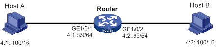
Because Host A's IPv6 address is on the same subnet as Host B's, Host A directly sends an NS message to obtain Host B's MAC address. However, Host B cannot receive the NS message because they belong to different broadcast domains.
To solve this problem, enable common ND proxy on GigabitEthernet 1/0/1 and GigabitEthernet 1/0/2 of the router. The router replies to the NS message from Host A, and forwards packets from other hosts to Host B.
· Local ND proxy.
As shown in Figure 91, Host A belongs to VLAN 2 and Host B belongs to VLAN 3. Host A and Host B connect to GigabitEthernet 1/0/1 and GigabitEthernet 1/0/3, respectively.
Figure 91 Application environment of local ND proxy
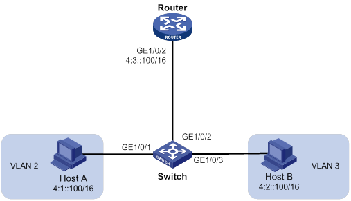
Because Host A's IPv6 address is on the same subnet as Host B's, Host A directly sends an NS message to obtain Host B's MAC address. However, Host B cannot receive the NS message because they belong to different VLANs.
To solve this problem, enable local ND proxy on GigabitEthernet 1/0/2 of the router so that the router can forward messages between Host A and Host B.
Local ND proxy implements Layer 3 communication for two hosts in the following cases:
? The two hosts connect to ports of the same device and the ports must be in different VLANs.
? The two hosts connect to isolated Layer 2 ports in the same isolation group of a VLAN.
? If super VLAN is used, the two hosts must belong to different sub VLANs.
? If Private VLAN is used, the two hosts must belong to different secondary VLANs.
Configuration procedure
You can enable common ND proxy and local ND proxy in VLAN interface view, Layer 3 Ethernet interface view, or Layer 3 Ethernet subinterface view.
To enable common ND proxy:
|
Step |
Command |
Remarks |
|
1. Enter system view. |
system-view |
N/A |
|
2. Enter interface view. |
interface interface-type interface-number |
N/A |
|
3. Enable common ND proxy. |
proxy-nd enable |
By default, common ND proxy is disabled. |
To enable local ND proxy:
|
Step |
Command |
Remarks |
|
1. Enter system view. |
system-view |
N/A |
|
2. Enter interface view. |
interface interface-type interface-number |
N/A |
|
3. Enable local ND proxy. |
local-proxy-nd enable |
By default, local ND proxy is disabled. |
Configuring IPv6 ND suppression
The following matrix shows the feature and hardware compatibility:
|
Hardware |
IPv6 ND suppression compatibility |
|
MSR810/810-W/810-W-DB/810-LM/810-W-LM/810-10-PoE/810-LM-HK/810-W-LM-HK |
Yes |
|
MSR810-LMS/810-LUS |
No |
|
MSR2600-6-X1/2600-10-X1 |
Yes |
|
MSR 2630 |
Yes |
|
MSR3600-28/3600-51 |
Yes |
|
MSR3600-28-SI/3600-51-SI |
No |
|
MSR3610-X1/3610-X1-DP/3610-X1-DC/3610-X1-DP-DC |
Yes |
|
MSR 3610/3620/3620-DP/3640/3660 |
Yes |
|
MSR5620/5660/5680 |
Yes |
|
Hardware |
IPv6 ND suppression compatibility |
|
MSR810-LM-GL |
Yes |
|
MSR810-W-LM-GL |
Yes |
|
MSR830-6EI-GL |
Yes |
|
MSR830-10EI-GL |
Yes |
|
MSR830-6HI-GL |
Yes |
|
MSR830-10HI-GL |
Yes |
|
MSR2600-6-X1-GL |
Yes |
|
MSR3600-28-SI-GL |
No |
The ND suppression feature enables a device to directly answer ND requests by using ND suppression entries. The device generates ND suppression entries based on dynamic ND entries that it learns. This feature is typically configured on the PEs connected to base stations in an L2VPN that provides access to an L3VPN network.
You can also configure the ND suppression push feature to push ND suppression entries at intervals by advertising NA messages.
Figure 92 shows a typical application scenario. ND suppression is enabled on the PE that connects to the base station. The PE generates ND suppression entries for the base station, PE-agg 1, and PE-agg 2, and it directly replies subsequent ND requests for these devices.

To configure the IPv6 ND suppression feature:
|
Step |
Command |
Remarks |
|
1. Enter system view. |
N/A |
|
|
2. Configure a cross-connect group and enter its view. |
By default, no cross-connect groups exist. For more information about the command, see MPLS Command Reference. |
|
|
3. Configure a cross-connect and enter it view. |
By default, no cross-connects exist. For more information about the command, see MPLS Command Reference. |
|
|
4. Enable IPv6 ND suppression. |
By default, the IPv6 ND suppression feature is disabled. |
|
|
5. Quit cross-connect view. |
quit |
N/A |
|
6. Quit cross-connect group view. |
quit |
N/A |
|
7. Enable the suppression push feature and set a push interval. |
By default, the ND suppression push feature is disabled. |
Configuring IPv6 ND direct route advertisement
The ND direct route advertisement feature advertises host routes instead of advertising the network route. This feature is typically configured on PE-aggs to advertise host routes to PEs in the L3VPN.
Figure 93 shows a typical application scenario where the PE in the L3VPN has ECMP routes destined to a base station in the L2VPN. Traffic from the PE in the L3VPN to the base station can be load shared by PE-agg 1 and PE-agg 2. If PE-agg 1 fails, the PE uses the host route through PE-agg 2 to forward traffic.
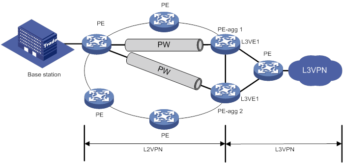
To configure ND direct route advertisement:
|
Step |
Command |
Remarks |
|
1. Enter system view. |
N/A |
|
|
2. Configure an L3VE interface and enter its view. |
By default, no L3VE interfaces exist. For more information about the command, see MPLS Command Reference. |
|
|
3. Enable ND direct route advertisement. |
By default, ND direct route advertisement is disabled. |
Configuring path MTU discovery
Setting the interface MTU
IPv6 routers do not support packet fragmentation. If the size of a packet exceeds the MTU of the output interface, the router discards the packet and sends a packet too big message to the source host. The source host fragments the packet according to the MTU. To avoid this situation, set a proper interface MTU.
To set the interface MTU:
|
Step |
Command |
Remarks |
|
1. Enter system view. |
system-view |
N/A |
|
2. Enter interface view. |
interface interface-type interface-number |
N/A |
|
3. Set the interface MTU. |
ipv6 mtu size |
By default, no interface MTU is set. |
Setting a static path MTU for an IPv6 address
You can set a static path MTU for an IPv6 address. Before sending a packet to the IPv6 address, the device compares the MTU of the output interface with the static path MTU. If the packet exceeds the smaller one of the two values, the device fragments the packet according to the smaller value. After sending the fragmented packets, the device dynamically finds the path MTU to a destination host (see "IPv6 path MTU discovery").
To set a static path MTU for a destination IPv6 address:
|
Step |
Command |
Remarks |
|
1. Enter system view. |
system-view |
N/A |
|
2. Set a static path MTU for a destination IPv6 address. |
ipv6 pathmtu [ vpn-instance vpn-instance-name ] ipv6-address value |
By default, no path MTU is set for any IPv6 address. |
Setting the aging time for dynamic path MTUs
After the device dynamically finds the path MTU to a destination host (see "IPv6 path MTU discovery"), it performs the following operations:
· Sends packets to the destination host based on the path MTU.
· Starts the aging timer.
When the aging timer expires, the device removes the dynamic path MTU and finds the path MTU again.
To set the aging time for dynamic path MTUs:
|
Step |
Command |
Remarks |
|
1. Enter system view. |
system-view |
N/A |
|
2. Set the aging time for dynamic path MTUs. |
ipv6 pathmtu age age-time |
The default setting is 10 minutes. The aging time is invalid for a static path MTU. |
Controlling sending ICMPv6 messages
This section describes how to configure ICMPv6 message sending.
Configuring the rate limit for ICMPv6 error messages
To avoid sending excessive ICMPv6 error messages within a short period that might cause network congestion, you can limit the rate at which ICMPv6 error messages are sent. A token bucket algorithm is used with one token representing one ICMPv6 error message.
A token is placed in the bucket at intervals until the maximum number of tokens that the bucket can hold is reached.
A token is removed from the bucket when an ICMPv6 error message is sent. When the bucket is empty, ICMPv6 error messages are not sent until a new token is placed in the bucket.
To configure the rate limit for ICMPv6 error messages:
|
Step |
Command |
Remarks |
|
1. Enter system view. |
system-view |
N/A |
|
2. Set the bucket size and the interval for tokens to arrive in the bucket for ICMPv6 error messages. |
ipv6 icmpv6 error-interval interval [ bucketsize ] |
By default, the bucket allows a maximum of 10 tokens. A token is placed in the bucket at an interval of 100 milliseconds. To disable the ICMPv6 rate limit, set the interval to 0 milliseconds. |
Enabling replying to multicast echo requests
The device does not respond to multicast echo requests by default. In some scenarios, you must enable the device to answer multicast echo requests so the source host can obtain needed information.
To enable the device to answer multicast echo requests:
|
Step |
Command |
Remarks |
|
1. Enter system view. |
system-view |
N/A |
|
2. Enable replying to multicast echo requests. |
ipv6 icmpv6 multicast-echo-reply enable |
By default, this feature is disabled. |
Enabling sending ICMPv6 destination unreachable messages
The device sends the source the following ICMPv6 destination unreachable messages:
· ICMPv6 No Route to Destination message—A packet to be forwarded does not match any route.
· ICMPv6 Communication with Destination Administratively Prohibited message—An administrative prohibition is preventing successful communication with the destination. This is typically caused by a firewall or an ACL on the device.
· ICMPv6 Beyond Scope of Source Address message—The destination is beyond the scope of the source IPv6 address. For example, a packet's source IPv6 address is a link-local address, and its destination IPv6 address is a global unicast address.
· ICMPv6 Address Unreachable message—The device fails to resolve the link layer address for the destination IPv6 address of a packet.
· ICMPv6 Port Unreachable message—No port process on the destination device exists for a received UDP packet.
If a device is generating ICMPv6 destination unreachable messages incorrectly, disable the sending of ICMPv6 destination unreachable messages to prevent attack risks.
To enable sending ICMPv6 destination unreachable messages:
|
Step |
Command |
Remarks |
|
1. Enter system view. |
system-view |
N/A |
|
2. Enable sending ICMPv6 destination unreachable messages. |
ipv6 unreachables enable |
By default, this feature is disabled. |
Enabling sending ICMPv6 time exceeded messages
The device sends the source ICMPv6 time exceeded messages as follows:
· If a received packet is not destined for the device and its hop limit is 1, the device sends an ICMPv6 hop limit exceeded in transit message to the source.
· Upon receiving the first fragment of an IPv6 datagram destined for the device, the device starts a timer. If the timer expires before all the fragments arrive, the device sends an ICMPv6 fragment reassembly time exceeded message to the source.
If the device receives large numbers of malicious packets, its performance degrades greatly because it must send back ICMP time exceeded messages. To prevent such attacks, disable sending ICMPv6 time exceeded messages.
To enable sending ICMPv6 time exceeded messages:
|
Step |
Command |
Remarks |
|
1. Enter system view. |
system-view |
N/A |
|
2. Enable sending ICMPv6 time exceeded messages. |
ipv6 hoplimit-expires enable |
The default setting is disabled. |
Enabling sending ICMPv6 redirect messages
Upon receiving a packet from a host, the device sends an ICMPv6 redirect message to inform the host of a better next hop when the following conditions are met:
· The interface receiving the packet is the interface forwarding the packet.
· The selected route is not created or modified by any ICMPv6 redirect messages.
· The selected route is not a default route.
· The forwarded packet does not contain the routing extension header.
The ICMPv6 redirect feature simplifies host management by enabling hosts that hold few routes to optimize their routing table gradually. However, to avoid adding too many routes on hosts, this feature is disabled by default.
To enable sending ICMPv6 redirect messages:
|
Step |
Command |
Remarks |
|
1. Enter system view. |
system-view |
N/A |
|
2. Enable sending ICMPv6 redirect messages. |
ipv6 redirects enable |
By default, sending ICMPv6 redirect messages is disabled. |
Specifying the source address for ICMPv6 packets
Perform this task to specify the source IPv6 address for outgoing ping echo requests and ICMPv6 error messages. It is a good practice to specify the IPv6 address of the loopback interface as the source IPv6 address. This feature helps users to easily locate the sending device.
If you specify an IPv6 address in the ping command, ping echo requests use the specified address as the source IPv6 address. Otherwise, ping echo requests use the IPv6 address specified by the ipv6 icmpv6 source command.
To specify the source IPv6 address for ICMPv6 packets:
|
Step |
Command |
Remarks |
|
1. Enter system view. |
system-view |
N/A |
|
2. Specify an IPv6 address as the source address for outgoing ICMPv6 packets. |
ipv6 icmpv6 source [ vpn-instance vpn-instance-name ] ipv6-address |
By default, the device uses the IPv6 address of the sending interface as the source IPv6 address for outgoing ICMPv6 packets. |
Enabling router renumbering
Router renumbering allows reconfiguration of address prefixes on IPv6 routers.
As shown in Figure 94, Router A sends RR messages to Router B, Router C, and Router D to change their prefix advertised in RAs. H3C devices can act as only downstream routers to receive RR messages. You must enable router renumbering on the interfaces on Router B, Router C, and Router D that connect to Router A.
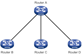
To enable router renumbering:
|
Step |
Command |
Remarks |
|
1. Enter system view. |
system-view |
N/A |
|
2. Enter interface view. |
interface interface-type interface-number |
N/A |
|
3. Enable router renumbering. |
By default, router renumbering is disabled. |
Enabling IPv6 local fragment reassembly
Perform this task on a distributed device to improve IPv6 local fragment reassembly efficiency. This feature allows the receiving LPU to reassemble the fragments of an IPv6 packet if all fragments arrive at it. If this feature is disabled, all fragments are delivered to the active MPU for reassembly.
To enable IPv6 local fragment reassembly:
|
Step |
Command |
Remarks |
|
1. Enter system view. |
system-view |
N/A |
|
2. Enable IPv6 local fragment reassembly. |
ipv6 reassemble local enable |
By default, IPv6 local fragment reassembly is disabled. This feature applies only to fragments destined for the same LPU. |
Configuring IPv6 load sharing based on bandwidth
This feature shares IPv6 traffic among multiple output interfaces based on their expected load percentages. The device calculates the load percentage for each output interface in terms of the interface expected bandwidth.
For devices that run load sharing protocols such as Locator/ID Separation Protocol (LISP), they implement load sharing based on the ratios defined by these protocols.
To configure IPv6 load sharing based on bandwidth:
|
Step |
Command |
Remarks |
|
1. Enter system view. |
system-view |
N/A |
|
2. Enable IPv6 load sharing based on bandwidth. |
By default, IPv6 bandwidth-based load sharing is disabled. |
|
|
3. Enter interface view. |
N/A |
|
|
4. Set the expected bandwidth of an interface. |
By default, the expected bandwidth of an interface equals the absolute bandwidth of the link. |
Enabling a device to discard IPv6 packets that contain extension headers
This feature enables a device to discard a received IPv6 packet in which the extension headers cannot be processed by the device.
To enable a device to discard IPv6 packets that contain extension headers:
|
Step |
Command |
Remarks |
|
1. Enter system view |
system-view |
N/A |
|
2. Enable the device to discard IPv6 packets that contain extension headers. |
ipv6 extension-header drop enable |
By default, the device does not discard IPv6 packets that contain extension headers. |
Displaying and maintaining IPv6 basics
Execute display commands in any view and reset commands in user view.
|
Task |
Command |
|
Display IPv6 FIB entries. |
display ipv6 fib [ vpn-instance vpn-instance-name ] [ ipv6-address [ prefix-length ] ] |
|
Display IPv6 information about the interface. |
display ipv6 interface [ interface-type [ interface-number ] ] [ brief ] |
|
Display IPv6 prefix information about the interface. |
display ipv6 interface interface-type interface-number prefix |
|
Display ND suppression entries (centralized devices in standalone mode). |
display ipv6 nd suppression xconnect-group [ name group-name ] [ count ] |
|
Display ND suppression entries (distributed devices in standalone mode/centralized devices in IRF mode). |
display ipv6 nd suppression xconnect-group [ name group-name ] [ slot slot-number ] [ count ] |
|
Display ND suppression entries (distributed devices in IRF mode). |
|
|
Display neighbor information (centralized devices in standalone mode). |
display ipv6 neighbors { ipv6-address | all | dynamic | interface interface-type interface-number | static | vlan vlan-id } [ verbose ] |
|
Display neighbor information (distributed devices in standalone mode/centralized devices in IRF mode). |
display ipv6 neighbors { { ipv6-address | all | dynamic | static } [ slot slot-number ] | interface interface-type interface-number | vlan vlan-id } [ verbose ] |
|
Display neighbor information (distributed devices in IRF mode). |
display ipv6 neighbors { { ipv6-address | all | dynamic | static } [ chassis chassis-number slot slot-number ] | interface interface-type interface-number | vlan vlan-id } [ verbose ] |
|
Display the total number of neighbor entries (centralized devices in standalone mode). |
display ipv6 neighbors { all | dynamic | interface interface-type interface-number | static | vlan vlan-id } count |
|
Display the total number of neighbor entries (distributed devices in standalone mode/centralized devices in IRF mode). |
display ipv6 neighbors { { all | dynamic | static } [ slot slot-number ] | interface interface-type interface-number | vlan vlan-id } count |
|
Display the total number of neighbor entries (distributed devices in IRF mode). |
display ipv6 neighbors { { all | dynamic | static } [ chassis chassis-number slot slot-number ] | interface interface-type interface-number | vlan vlan-id } count |
|
Display neighbor information for a VPN. |
display ipv6 neighbors vpn-instance vpn-instance-name [ count ] |
|
Display the IPv6 path MTU information. |
display ipv6 pathmtu [ vpn-instance vpn-instance-name ] { ipv6-address | { all | dynamic | static } [ count ] } |
|
Display the IPv6 prefix information. |
|
|
Display IPv6 and ICMPv6 packet statistics (centralized devices in standalone mode). |
display ipv6 statistics |
|
Display IPv6 and ICMPv6 statistics (distributed devices in standalone mode/centralized devices in IRF mode). |
display ipv6 statistics [ slot slot-number ] |
|
Display IPv6 and ICMPv6 statistics (distributed devices in IRF mode). |
display ipv6 statistics [ chassis chassis-number slot slot-number ] |
|
Display brief information about IPv6 RawIP connections (centralized devices in standalone mode). |
display ipv6 rawip |
|
Display brief information about IPv6 RawIP connections (distributed devices in standalone mode/centralized devices in IRF mode). |
display ipv6 rawip [ slot slot-number ] |
|
Display brief information about IPv6 RawIP connections (distributed devices in IRF mode). |
display ipv6 rawip [ chassis chassis-number slot slot-number ] |
|
Display detailed information about IPv6 RawIP connections (centralized devices in standalone mode). |
display ipv6 rawip verbose [ pcb pcb-index ] |
|
Display detailed information about IPv6 RawIP connections (distributed devices in standalone mode/centralized devices in IRF mode). |
display ipv6 rawip verbose [ slot slot-number [ pcb pcb-index ] ] |
|
Display detailed information about IPv6 RawIP connections (distributed devices in IRF mode). |
display ipv6 rawip verbose [ chassis chassis-number slot slot-number [ pcb pcb-index ] ] |
|
Display router renumbering statistics. |
|
|
Display brief information about IPv6 TCP connections (centralized devices in standalone mode). |
display ipv6 tcp |
|
Display brief information about IPv6 TCP connections (distributed devices in standalone mode/centralized devices in IRF mode). |
display ipv6 tcp [ slot slot-number ] |
|
Display brief information about IPv6 TCP connections (distributed devices in IRF mode). |
display ipv6 tcp [ chassis chassis-number slot slot-number ] |
|
Display brief information about IPv6 TCP proxy (centralized devices in standalone mode). |
|
|
Display brief information about IPv6 TCP proxy (distributed devices in standalone mode/centralized devices in IRF mode). |
|
|
Display brief information about IPv6 TCP proxy (distributed devices in IRF mode). |
display ipv6 tcp-proxy chassis chassis-number slot slot-number |
|
Display the usage of non-well known ports for IPv6 TCP proxy (centralized devices in standalone mode). |
display ipv6 tcp-proxy port-info |
|
Display the usage of non-well known ports for IPv6 TCP proxy (distributed devices in standalone mode/centralized devices in IRF mode). |
display ipv6 tcp-proxy port-info slot slot-number |
|
Display the usage of non-well known ports for IPv6 TCP proxy (distributed devices in IRF mode). |
display ipv6 tcp-proxy port-info chassis chassis-number slot slot-number |
|
Display detailed information about IPv6 TCP connections (centralized devices in standalone mode). |
display ipv6 tcp verbose [ pcb pcb-index ] |
|
Display detailed information about IPv6 TCP connections (distributed devices in standalone mode/centralized devices in IRF mode). |
display ipv6 tcp verbose [ slot slot-number [ pcb pcb-index ] ] |
|
Display detailed information about IPv6 TCP connections (distributed devices in IRF mode). |
display ipv6 tcp verbose [ chassis chassis-number slot slot-number [ pcb pcb-index ] ] |
|
Display brief information about IPv6 UDP connections (centralized devices in standalone mode). |
display ipv6 udp |
|
Display brief information about IPv6 UDP connections (distributed devices in standalone mode/centralized devices in IRF mode). |
display ipv6 udp [ slot slot-number ] |
|
Display brief information about IPv6 UDP connections (distributed devices in IRF mode). |
display ipv6 udp [ chassis chassis-number slot slot-number ] |
|
Display detailed information about IPv6 UDP connections (centralized devices in standalone mode). |
display ipv6 udp verbose [ pcb pcb-index ] |
|
Display detailed information about IPv6 UDP connections (distributed devices in standalone mode/centralized devices in IRF mode). |
display ipv6 udp verbose [ slot slot-number [ pcb pcb-index ] ] |
|
Display detailed information about IPv6 UDP connections (distributed devices in IRF mode). |
display ipv6 udp verbose [ chassis chassis-number slot slot-number [ pcb pcb-index ] ] |
|
Display ICMPv6 traffic statistics (centralized devices in standalone mode). |
display ipv6 icmp statistics |
|
Display ICMPv6 traffic statistics (distributed devices in standalone mode/centralized devices in IRF mode). |
display ipv6 icmp statistics [ slot slot-number ] |
|
Display ICMPv6 traffic statistics (distributed devices in IRF mode). |
display ipv6 icmp statistics [ chassis chassis-number slot slot-number ] |
|
Display IPv6 TCP traffic statistics (centralized devices in standalone mode). |
display tcp statistics |
|
Display IPv6 TCP traffic statistics (distributed devices in standalone mode/centralized devices in IRF mode). |
display tcp statistics [ slot slot-number ] |
|
Display IPv6 TCP traffic statistics (distributed devices in IRF mode). |
display tcp statistics [ chassis chassis-number slot slot-number ] |
|
Display IPv6 UDP traffic statistics (centralized devices in standalone mode). |
display udp statistics |
|
Display IPv6 UDP traffic statistics (distributed devices in standalone mode/centralized devices in IRF mode). |
display udp statistics [ slot slot-number ] |
|
Display IPv6 UDP traffic statistics (distributed devices in IRF mode). |
display udp statistics [ chassis chassis-number slot slot-number ] |
|
Clear ND suppression entries (centralized devices in standalone mode). |
reset ipv6 nd suppression xconnect-group [ name group-name ] |
|
Clear ND suppression entries (distributed devices in standalone mode/centralized devices in IRF mode). |
reset ipv6 nd suppression xconnect-group [ name group-name ] [ slot slot-number ] |
|
Clear ND suppression entries (distributed devices in IRF mode). |
|
|
Clear IPv6 neighbor information (centralized devices in standalone mode). |
reset ipv6 neighbors { all | dynamic | interface interface-type interface-number | static } |
|
Clear IPv6 neighbor information (distributed devices in standalone mode/centralized devices in IRF mode). |
reset ipv6 neighbors { all | dynamic | interface interface-type interface-number | slot slot-number | static } |
|
Clear IPv6 neighbor information (distributed devices in IRF mode). |
reset ipv6 neighbors { all | dynamic | interface interface-type interface-number | chassis chassis-number slot slot-number | static } |
|
Clear path MTUs. |
reset ipv6 pathmtu { all | dynamic | static } |
|
Clear router renumbering statistics. |
|
|
Clear IPv6 and ICMPv6 packet statistics (centralized devices in standalone mode). |
reset ipv6 statistics |
|
Clear IPv6 and ICMPv6 packet statistics (distributed devices in standalone mode/centralized devices in IRF mode). |
reset ipv6 statistics [ slot slot-number ] |
|
Clear IPv6 and ICMPv6 packet statistics (distributed devices in IRF mode). |
reset ipv6 statistics [ chassis chassis-number slot slot-number ] |
|
Clear IPv6 TCP traffic statistics. |
reset tcp statistics |
|
Clear IPv6 UDP traffic statistics. |
reset udp statistics |
IPv6 configuration examples
Basic IPv6 configuration example
Network requirements
As shown in Figure 95, configure IPv6 addresses for the routers and verify that they can reach each other. Configure a route to the host on Router B. Enable IPv6 for the host to automatically obtain an IPv6 address through IPv6 ND. The host has a route to Router B.
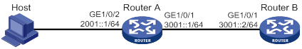
Configuration procedure
1. Configure Router A:
# Configure a global unicast address for interface GigabitEthernet 1/0/1.
<RouterA> system-view
[RouterA] interface gigabitethernet 1/0/1
[RouterA-GigabitEthernet1/0/1] ipv6 address 3001::1/64
[RouterA-GigabitEthernet1/0/1] quit
# Configure a global unicast address for interface GigabitEthernet 1/0/2 and enable it to advertise RA messages (an interface does not advertises RA messages by default).
[RouterA] interface gigabitethernet 1/0/2
[RouterA-GigabitEthernet1/0/2] ipv6 address 2001::1/64
[RouterA-GigabitEthernet1/0/2] undo ipv6 nd ra halt
[RouterA-GigabitEthernet1/0/2] quit
2. Configure Router B:
# Configure a global unicast address for interface GigabitEthernet 1/0/1.
<RouterB> system-view
[RouterB] interface gigabitethernet 1/0/1
[RouterB-GigabitEthernet1/0/1] ipv6 address 3001::2/64
[RouterB-GigabitEthernet1/0/1] quit
# Configure an IPv6 static route to the host.
[RouterB] ipv6 route-static 2001:: 64 3001::1
3. Configure the host:
Enable IPv6 on the host to automatically obtain an IPv6 address through IPv6 ND.
# Display neighbor information for GigabitEthernet 1/0/2 on Router A.
[RouterA] display ipv6 neighbors interface gigabitethernet 1/0/2
Type: S-Static D-Dynamic O-Openflow R-Rule I-Invalid
IPv6 address Link Layer VID Interface State T Age
FE80::215:E9FF:FEA6:7D14 0015-e9a6-7d14 N/A GE1/0/2 STALE D 1238
2001::15B:E0EA:3524:E791 0015-e9a6-7d14 N/A GE1/0/2 STALE D 1248
The output shows that the IPv6 global unicast address that the host obtained is 2001::15B:E0EA:3524:E791.
Verifying the configuration
# Display IPv6 interface information on Router A.
[RouterA] display ipv6 interface gigabitethernet 1/0/1
GigabitEthernet1/0/1 current state: UP
Line protocol current state: UP
IPv6 is enabled, link-local address is FE80::20F:E2FF:FE00:2
Global unicast address(es):
3001::1, subnet is 3001::/64
Joined group address(es):
FF02::1
FF02::2
FF02::1:FF00:1
FF02::1:FF00:2
MTU is 1500 bytes
ND DAD is enabled, number of DAD attempts: 1
ND reachable time is 30000 milliseconds
ND retransmit interval is 1000 milliseconds
Hosts use stateless autoconfig for addresses
IPv6 Packet statistics:
InReceives: 25829
InTooShorts: 0
InTruncatedPkts: 0
InHopLimitExceeds: 0
InBadHeaders: 0
InBadOptions: 0
ReasmReqds: 0
ReasmOKs: 0
InFragDrops: 0
InFragTimeouts: 0
OutFragFails: 0
InUnknownProtos: 0
InDelivers: 47
OutRequests: 89
OutForwDatagrams: 48
InNoRoutes: 0
InTooBigErrors: 0
OutFragOKs: 0
OutFragCreates: 0
InMcastPkts: 6
InMcastNotMembers: 25747
OutMcastPkts: 48
InAddrErrors: 0
InDiscards: 0
OutDiscards: 0
[RouterA] display ipv6 interface gigabitethernet 1/0/2
GigabitEthernet1/0/2 current state: UP
Line protocol current state: UP
IPv6 is enabled, link-local address is FE80::20F:E2FF:FE00:1C0
Global unicast address(es):
2001::1, subnet is 2001::/64
Joined group address(es):
FF02::1
FF02::2
FF02::1:FF00:1
FF02::1:FF00:1C0
MTU is 1500 bytes
ND DAD is enabled, number of DAD attempts: 1
ND reachable time is 30000 milliseconds
ND retransmit interval is 1000 milliseconds
ND advertised reachable time is 0 milliseconds
ND advertised retransmit interval is 0 milliseconds
ND router advertisements are sent every 600 seconds
ND router advertisements live for 1800 seconds
Hosts use stateless autoconfig for addresses
IPv6 Packet statistics:
InReceives: 272
InTooShorts: 0
InTruncatedPkts: 0
InHopLimitExceeds: 0
InBadHeaders: 0
InBadOptions: 0
ReasmReqds: 0
ReasmOKs: 0
InFragDrops: 0
InFragTimeouts: 0
OutFragFails: 0
InUnknownProtos: 0
InDelivers: 159
OutRequests: 1012
OutForwDatagrams: 35
InNoRoutes: 0
InTooBigErrors: 0
OutFragOKs: 0
OutFragCreates: 0
InMcastPkts: 79
InMcastNotMembers: 65
OutMcastPkts: 938
InAddrErrors: 0
InDiscards: 0
OutDiscards: 0
# Display IPv6 interface information on Router B.
[RouterB] display ipv6 interface gigabitethernet 1/0/1
GigabitEthernet1/0/1 current state: UP
Line protocol current state: UP
IPv6 is enabled, link-local address is FE80::20F:E2FF:FE00:1234
Global unicast address(es):
3001::2, subnet is 3001::/64
Joined group address(es):
FF02::1
FF02::2
FF02::1:FF00:2
FF02::1:FF00:1234
MTU is 1500 bytes
ND DAD is enabled, number of DAD attempts: 1
ND reachable time is 30000 milliseconds
ND retransmit interval is 1000 milliseconds
Hosts use stateless autoconfig for addresses
IPv6 Packet statistics:
InReceives: 117
InTooShorts: 0
InTruncatedPkts: 0
InHopLimitExceeds: 0
InBadHeaders: 0
InBadOptions: 0
ReasmReqds: 0
ReasmOKs: 0
InFragDrops: 0
InFragTimeouts: 0
OutFragFails: 0
InUnknownProtos: 0
InDelivers: 117
OutRequests: 83
OutForwDatagrams: 0
InNoRoutes: 0
InTooBigErrors: 0
OutFragOKs: 0
OutFragCreates: 0
InMcastPkts: 28
InMcastNotMembers: 0
OutMcastPkts: 7
InAddrErrors: 0
InDiscards: 0
OutDiscards: 0
# Ping Router A and Router B from the host, and ping Router A and the host from Router B to verify that they can reach each other.
|
|
NOTE: To ping a link-local address, use the –i parameter to specify an interface for the link-local address. |
[RouterB] ping ipv6 -c 1 3001::1
Ping6(56 data bytes) 3001::2 --> 3001::1, press CTRL_C to break
56 bytes from 3001::1, icmp_seq=0 hlim=64 time=4.404 ms
--- Ping6 statistics for 3001::1 ---
1 packet(s) transmitted, 1 packet(s) received, 0.0% packet loss
round-trip min/avg/max/std-dev = 4.404/4.404/4.404/0.000 ms
[RouterB] ping ipv6 -c 1 2001::15B:E0EA:3524:E791
Ping6(56 data bytes) 3001::2 --> 2001::15B:E0EA:3524:E791, press CTRL_C to break
56 bytes from 2001::15B:E0EA:3524:E791, icmp_seq=0 hlim=64 time=5.404 ms
--- Ping6 statistics for 2001::15B:E0EA:3524:E791 ---
1 packet(s) transmitted, 1 packet(s) received, 0.0% packet loss
round-trip min/avg/max/std-dev = 5.404/5.404/5.404/0.000 ms
The output shows that Router B can ping Router A and the host. The host can also ping Router B and Router A (output not shown).
IPv6 ND suppression configuration example
Network requirements
As shown in Figure 96, the base station, Router A, and Router B are in an MPLS L2VPN. The base station can reach the L3VE interface L3VE1 of Router B.
Enable IPv6 ND suppression on Router A to directly answer ND messages for Router B.
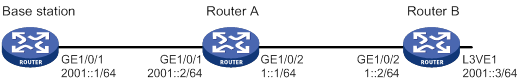
Configuration procedure
1. Configure IPv6 addresses for the interfaces as shown in Figure 96. Make sure the base station can reach the L3VE interface of Router B. (Details not shown.)
2. Configure IPv6 ND suppression:
# Create a cross-connect group named vpna.
<RouterA> system-view
[RouterA] xconnect-group vpna
# Create a cross-connect named svc.
[RouterA-xcg-vpna] connection svc
# Enable IPv6 ND suppression for the cross-connect svc in cross-connect group vpna.
[RouterA-xcg-vpna-svc] ipv6 nd suppression enable
Verifying the configuration
1. On the base station, clear the ND suppression entries, and ping the L3VE interface VE-L3VPN 1 of Router B. (Details not shown.)
2. Verify that Router A has ND suppression entries for the base station and Router B.
[RouterA-xcg-vpna-svc] display ipv6 nd suppression xconnect-group
IPv6 address MAC address Xconnect-group Connection Aging
2001::1 00e0-fc04-582c vpna svc 25
2001::3 0023-89b7-0861 vpna svc 25
3. Enable ND debugging on Router B to verify that Router B does not receive an ND request from the base station when the following conditions exist (details not shown):
a. Clear ND suppression entries on the base station.
b. Ping L3VE interface VE-L3VPN 1 of Router B from the base station.
Troubleshooting IPv6 basics configuration
Symptom
An IPv6 address cannot be pinged.
Solution
1. Use the display ipv6 interface command in any view to verify that the IPv6 address of the output interface is correct and the interface is up.
2. Use the debugging ipv6 packet command in user view to enable the debugging for IPv6 packets to locate the fault.
DHCPv6 overview
DHCPv6 address/prefix assignment
An address/prefix assignment process involves two or four messages.
Rapid assignment involving two messages
As shown in Figure 97, rapid assignment operates in the following steps:
1. The DHCPv6 client sends to the DHCPv6 server a Solicit message that contains a Rapid Commit option to prefer rapid assignment.
2. If the DHCPv6 server supports rapid assignment, it responds with a Reply message containing the assigned IPv6 address/prefix and other configuration parameters. If the DHCPv6 server does not support rapid assignment, Assignment involving four messages is performed.
Figure 97 Rapid assignment involving two messages
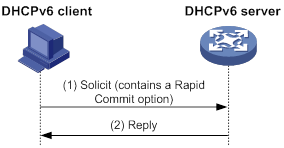
Assignment involving four messages
As shown in Figure 98, four-message assignment operates using the following steps:
1. The DHCPv6 client sends a Solicit message to request an IPv6 address/prefix and other configuration parameters.
2. The DHCPv6 server responds with an Advertise message that contains the assignable address/prefix and other configuration parameters if either of the following conditions exists:
? The Solicit message does not contain a Rapid Commit option.
? The DHCPv6 server does not support rapid assignment even though the Solicit message contains a Rapid Commit option.
3. The DHCPv6 client might receive multiple Advertise messages offered by different DHCPv6 servers. It selects an offer according to the receiving sequence and server priority, and sends a Request message to the selected server for confirmation.
4. The DHCPv6 server sends a Reply message to the client, confirming that the address/prefix and other configuration parameters are assigned to the client.
Figure 98 Assignment involving four messages
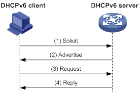
Address/prefix lease renewal
An IPv6 address/prefix assigned by a DHCPv6 server has a valid lifetime. After the valid lifetime expires, the DHCPv6 client cannot use the IPv6 address/prefix. To use the IPv6 address/prefix, the DHCPv6 client must renew the lease time.
Figure 99 Using the Renew message for address/prefix lease renewal
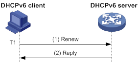
As shown in Figure 99, at T1, the DHCPv6 client sends a Renew message to the DHCPv6 server. The recommended value of T1 is half the preferred lifetime. The DHCPv6 server responds with a Reply message, informing the client whether the lease is renewed.
Figure 100 Using the Rebind message for address/prefix lease renewal
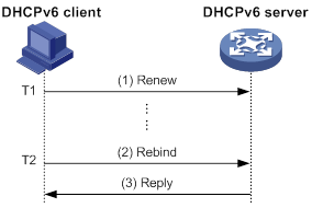
As shown in Figure 100:
· If the DHCPv6 client does not receive a response from the DHCPv6 server after sending a Renew message at T1, it multicasts a Rebind message to all DHCPv6 servers at T2. Typically, the value of T2 is 0.8 times the preferred lifetime.
· The DHCPv6 server responds with a Reply message, informing the client whether the lease is renewed.
· If the DHCPv6 client does not receive a response from any DHCPv6 server before the valid lifetime expires, the client stops using the address/prefix.
For more information about the valid lifetime and the preferred lifetime, see "Configuring basic IPv6 settings."
Stateless DHCPv6
Stateless DHCPv6 enables a device that has obtained an IPv6 address/prefix to get other configuration parameters from a DHCPv6 server.
The device performs stateless DHCPv6 if an RA message with the following flags is received from the router during stateless address autoconfiguration:
· The managed address configuration flag (M flag) is set to 0.
· The other stateful configuration flag (O flag) is set to 1.
For more information about stateless address autoconfiguration, see "Configuring basic IPv6 settings."
Figure 101 Stateless DHCPv6 operation
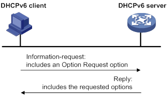
As shown in Figure 101, stateless DHCPv6 operates in the following steps:
1. The DHCPv6 client sends an Information-request message to the multicast address of all DHCPv6 servers and DHCPv6 relay agents. The Information-request message contains an Option Request option that specifies the requested configuration parameters.
2. The DHCPv6 server returns to the client a Reply message containing the requested configuration parameters.
3. The client checks the Reply message. If the obtained configuration parameters match those requested in the Information-request message, the client uses these parameters to complete configuration. If not, the client ignores the configuration parameters. If the client receives multiple replies with configuration parameters matching those requested in the Information-request message, it uses the first received reply.
Compatibility information
Feature and hardware compatibility
DHCPv6 features are not supported on the following routers:
· MSR810/810-W/810-W-DB/810-LM/810-W-LM/810-10-PoE/810-LM-HK/810-W-LM-HK/810-LMS/810-LUS.
· MSR3600-28-SI/3600-51-SI.
Command and hardware compatibility
Commands and descriptions for centralized devices apply to the following routers:
· MSR810/810-W/810-W-DB/810-LM/810-W-LM/810-10-PoE/810-LM-HK/810-W-LM-HK/810-LMS/810-LUS.
· MSR2600-6-X1/2600-10-X1.
· MSR 2630.
· MSR3600-28/3600-51.
· MSR3600-28-SI/3600-51-SI.
· MSR3610-X1/3610-X1-DP/3610-X1-DC/3610-X1-DP-DC.
· MSR 3610/3620/3620-DP/3640/3660.
· MSR810-LM-GL/810-W-LM-GL/830-6EI-GL/830-10EI-GL/830-6HI-GL/830-10HI-GL/2600-6-X1-GL/3600-28-SI-GL.
Commands and descriptions for distributed devices apply to the following routers:
· MSR5620.
· MSR 5660.
· MSR 5680.
Protocols and standards
· RFC 3736, Stateless Dynamic Host Configuration Protocol (DHCP) Service for IPv6
· RFC 3315, Dynamic Host Configuration Protocol for IPv6 (DHCPv6)
· RFC 2462, IPv6 Stateless Address Autoconfiguration
· RFC 3633, IPv6 Prefix Options for Dynamic Host Configuration Protocol (DHCP) version 6
Configuring the DHCPv6 server
Overview
IPv6 address assignment
As shown in Figure 102, the DHCPv6 server assigns IPv6 addresses, domain name suffixes, DNS server addresses, and other configuration parameters to DHCPv6 clients.
The IPv6 addresses assigned to the clients include the following types:
· Temporary IPv6 addresses—Frequently changed without lease renewal.
· Non-temporary IPv6 addresses—Correctly used by DHCP clients, with lease renewal.
Figure 102 IPv6 address assignment
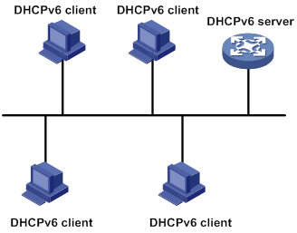
IPv6 prefix assignment
As shown in Figure 103, the DHCPv6 server assigns an IPv6 prefix to the DHCPv6 client. The client advertises the prefix information in a multicast RA message so that hosts on the subnet can automatically configure their IPv6 addresses by using the prefix.
Figure 103 IPv6 prefix assignment
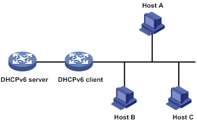
Concepts
Multicast addresses used by DHCPv6
DHCPv6 uses the multicast address FF05::1:3 to identify all site-local DHCPv6 servers. It uses the multicast address FF02::1:2 to identify all link-local DHCPv6 servers and relay agents.
DUID
A DHCP unique identifier (DUID) uniquely identifies a DHCPv6 device (DHCPv6 client, server, or relay agent). A DHCPv6 device adds its DUID in a sent packet.
Figure 104 DUID-LL format
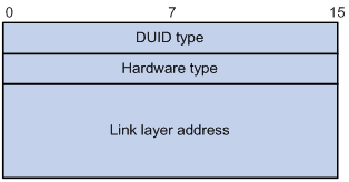
The device supports the DUID format based on link-layer address (DUID-LL) defined in RFC 3315. Figure 104 shows the DUID-LL format, which includes the following fields:
· DUID type—The device supports the DUID type of DUID-LL with the value of 0x0003.
· Hardware type—The device supports the hardware type of Ethernet with the value of 0x0001.
· Link layer address—Takes the value of the bridge MAC address of the device.
IA
Identified by an IAID, an identity association (IA) provides a construct through which a client manages the obtained addresses, prefixes, and other configuration parameters. A client can have multiple IAs, for example, one for each of its interfaces.
IAID
An IAID uniquely identifies an IA. It is chosen by the client and must be unique on the client.
PD
The DHCPv6 server creates a prefix delegation (PD) for each assigned prefix to record the following details:
· IPv6 prefix.
· Client DUID.
· IAID.
· Valid lifetime.
· Preferred lifetime.
· Lease expiration time.
· IPv6 address of the requesting client.
DHCPv6 address pool
The DHCP server selects IPv6 addresses, IPv6 prefixes, and other parameters from an address pool, and assigns them to the DHCP clients.
Address allocation mechanisms
DHCPv6 supports the following address allocation mechanisms:
· Static address allocation—To implement static address allocation for a client, create a DHCPv6 address pool, and manually bind the DUID and IAID of the client to an IPv6 address in the DHCPv6 address pool. When the client requests an IPv6 address, the DHCPv6 server assigns the IPv6 address in the static binding to the client.
· Dynamic address allocation—To implement dynamic address allocation for clients, create a DHCPv6 address pool, specify a subnet for the pool, and divide the subnet into temporary and non-temporary IPv6 address ranges. Upon receiving a DHCP request, the DHCPv6 server selects an IPv6 address from the temporary or non-temporary IPv6 address range based on the address type in the client request.
Prefix allocation mechanisms
DHCPv6 supports the following prefix allocation mechanisms:
· Static prefix allocation—To implement static prefix allocation for a client, create a DHCPv6 address pool, and manually bind the DUID and IAID of the client to an IPv6 prefix in the DHCPv6 address pool. When the client requests an IPv6 prefix, the DHCPv6 server assigns the IPv6 prefix in the static binding to the client.
· Dynamic prefix allocation—To implement dynamic prefix allocation for clients, create a DHCPv6 address pool and a prefix pool, specify a subnet for the address pool, and apply the prefix pool to the address pool. Upon receiving a DHCP request, the DHCPv6 server dynamically selects an IPv6 prefix from the prefix pool in the address pool.
Address pool selection
The DHCPv6 server observes the following principles when selecting an IPv6 address or prefix for a client:
1. If there is an address pool where an IPv6 address is statically bound to the DUID or IAID of the client, the DHCPv6 server selects this address pool. It assigns the statically bound IPv6 address or prefix and other configuration parameters to the client.
2. If the receiving interface has an address pool applied, the DHCP server selects an IPv6 address or prefix and other configuration parameters from this address pool.
3. If no static address pool is configured and no address pool is applied to the receiving interface, the DHCPv6 server selects an address pool depending on the client location.
? Client on the same subnet as the server—The DHCPv6 server compares the IPv6 address of the receiving interface with the subnets of all address pools. It selects the address pool with the longest-matching subnet.
? Client on a different subnet than the server—The DHCPv6 server compares the IPv6 address of the DHCPv6 relay agent interface closest to the client with the subnets of all address pools. It also selects the address pool with the longest-matching subnet.
To make sure IPv6 address allocation functions correctly, keep the subnet used for dynamic assignment consistent with the subnet where the interface of the DHCPv6 server or DHCPv6 relay agent resides.
IPv6 address/prefix allocation sequence
The DHCPv6 server selects an IPv6 address/prefix for a client in the following sequence:
1. IPv6 address/prefix statically bound to the client's DUID and IAID and expected by the client.
2. IPv6 address/prefix statically bound to the client's DUID and IAID.
3. IPv6 address/prefix statically bound to the client's DUID and expected by the client.
4. IPv6 address/prefix statically bound to the client's DUID.
5. IPv6 address/prefix that was ever assigned to the client.
6. Assignable IPv6 address/prefix in the address pool/prefix pool expected by the client.
7. Assignable IPv6 address/prefix in the address pool/prefix pool.
8. IPv6 address/prefix that was a conflict or passed its lease duration. If no IPv6 address/prefix is assignable, the server does not respond.
If a client moves to another subnet, the DHCPv6 server selects an IPv6 address/prefix from the address pool that matches the new subnet.
Conflicted IPv6 addresses can be assigned to other DHCPv6 clients only after the addresses are in conflict for one hour.
Compatibility information
Feature and hardware compatibility
DHCPv6 features are not supported on the following routers:
· MSR810/810-W/810-W-DB/810-LM/810-W-LM/810-10-PoE/810-LM-HK/810-W-LM-HK/810-LMS/810-LUS.
· MSR3600-28-SI/3600-51-SI.
Command and hardware compatibility
Commands and descriptions for centralized devices apply to the following routers:
· MSR810/810-W/810-W-DB/810-LM/810-W-LM/810-10-PoE/810-LM-HK/810-W-LM-HK/810-LMS/810-LUS.
· MSR2600-6-X1/2600-10-X1.
· MSR 2630.
· MSR3600-28/3600-51.
· MSR3600-28-SI/3600-51-SI.
· MSR3610-X1/3610-X1-DP/3610-X1-DC/3610-X1-DP-DC.
· MSR 3610/3620/3620-DP/3640/3660.
Commands and descriptions for distributed devices apply to the following routers:
· MSR5620.
· MSR 5660.
· MSR 5680.
Configuration task list
|
Tasks at a glance |
|
(Optional.) Perform the following tasks: · Configu ring IPv6 prefix assignment · Configuring IPv6 address assignment · Configuring network parameters assignment · Configuring a DHCPv6 policy for IPv6 address and prefix assignment |
|
(Required.) Configuring the DHCPv6 server on an interface |
|
(Optional.) Setting the DSCP value for DHCPv6 packets sent by the DHCPv6 server |
|
(Optional.) Configuring DHCPv6 binding auto backup |
|
(Optional.) Advertising subnets assigned to clients |
|
(Optional.) Applying a DHCPv6 address pool to a VPN instance |
|
(Optional.) Enabling DHCPv6 logging on the DHCPv6 server |
Configuring IPv6 prefix assignment
Use the following methods to configure IPv6 prefix assignment:
· Configure a static IPv6 prefix binding in an address pool—If you bind a DUID and an IAID to an IPv6 prefix, the DUID and IAID in a request must match those in the binding before the DHCPv6 server can assign the IPv6 prefix to the DHCPv6 client. If you only bind a DUID to an IPv6 prefix, the DUID in the request must match the DUID in the binding before the DHCPv6 server can assign the IPv6 prefix to the DHCPv6 client.
· Apply a prefix pool to an address pool—The DHCPv6 server dynamically assigns an IPv6 prefix from the prefix pool in the address pool to a DHCPv6 client.
Configuration guidelines
· An IPv6 prefix can be bound to only one DHCPv6 client. You cannot modify bindings that have been created. To change the binding for a DHCPv6 client, you must delete the existing binding first.
· Only one prefix pool can be applied to an address pool. You cannot modify prefix pools that have been applied. To change the prefix pool for an address pool, you must remove the prefix pool application first.
· You can apply a prefix pool that has not been created to an address pool. The setting takes effect after the prefix pool is created.
Configuration procedure
To configure IPv6 prefix assignment:
|
Step |
Command |
Remarks |
|
1. Enter system view. |
system-view |
N/A |
|
2. (Optional.) Specify the IPv6 prefixes excluded from dynamic assignment. |
ipv6 dhcp server forbidden-prefix start-prefix/prefix-len [ end-prefix/prefix-len ] [ vpn-instance vpn-instance-name ] |
By default, no IPv6 prefixes in the prefix pool are excluded from dynamic assignment. If the excluded IPv6 prefix is in a static binding, the prefix still can be assigned to the client. To exclude multiple IPv6 prefix ranges, repeat this step. |
|
3. Create a prefix pool. |
ipv6 dhcp prefix-pool prefix-pool-number prefix { prefix-number | prefix/prefix-len } assign-len assign-len [ vpn-instance vpn-instance-name ] |
This step is required for dynamic prefix assignment. By default, no prefix pools exist. If you specify an IPv6 prefix by its ID, make sure the IPv6 prefix is in effect. Otherwise, the configuration does not take effect. |
|
4. Create a DHCPv6 address pool and enter its view. |
ipv6 dhcp pool pool-name |
By default, no DHCPv6 address pools exist. |
|
5. Specify an IPv6 subnet for dynamic assignment. |
network { prefix/prefix-length | prefix prefix-number [ sub-prefix/sub-prefix-length ] } [ preferred-lifetime preferred-lifetime valid-lifetime valid-lifetime ] |
By default, no IPv6 subnet is specified for dynamic assignment. The IPv6 subnets cannot be the same in different address pools. If you specify an IPv6 prefix by its ID, make sure the IPv6 prefix is in effect. Otherwise, the configuration does not take effect. |
|
6. Configure static prefix assignment, dynamic prefix assignment, or both. |
·
Configure a static prefix binding: ·
Apply the prefix pool to the address
pool: |
By default, static or dynamic prefix assignment is not configured for an address pool. To add multiple static IPv6 prefix bindings, use the static-bind prefix command multiple times. |
Configuring IPv6 address assignment
Use one of the following methods to configure IPv6 address assignment:
· Configure a static IPv6 address binding in an address pool.
If you bind a DUID and an IAID to an IPv6 address, the DUID and IAID in a request must match those in the binding before the DHCPv6 server can assign the IPv6 address to the requesting client. If you only bind a DUID to an IPv6 address, the DUID in a request must match the DUID in the binding before the DHCPv6 server can assign the IPv6 address to the requesting client.
· Specify a subnet and address ranges in an address pool.
? Non-temporary address assignment—The server selects addresses from the non-temporary address range specified by the address range command. If no non-temporary address range is specified, the server selects addresses on the subnet specified by the network command.
? Temporary address assignment—The server selects addresses from the temporary address range specified by the temporary address range command. If no temporary address range is specified in the address pool, the DHCPv6 server cannot assign temporary addresses to clients.
Configuration guidelines
· You can specify only one non-temporary address range and one temporary address range in an address pool.
· The address ranges specified by the address range and temporary address range commands must be on the subnet specified by the network command. Otherwise, the addresses are unassignable.
· Only one prefix pool can be applied to an address pool. You can apply a prefix pool that has not been created to an address pool. The setting takes effect after the prefix pool is created.
· An IPv6 address can be bound to only one DHCPv6 client. You cannot modify bindings that have been created. To change the binding for a DHCPv6 client, you must delete the existing binding first.
· Only one subnet can be specified in an address pool. If you use the network command multiple times in a DHCPv6 address pool, the most recent configuration takes effect. If you use this command to specify only new lifetimes, the settings do not affect existing leases. The IPv6 addresses assigned after the modification will use the new lifetimes.
Configuration procedure
To configure IPv6 address assignment:
|
Step |
Command |
Remarks |
|
1. Enter system view. |
system-view |
N/A |
|
2. (Optional.) Specify the IPv6 addresses excluded from dynamic assignment. |
ipv6 dhcp server forbidden-address start-ipv6-address [ end-ipv6-address ] [ vpn-instance vpn-instance-name ] |
By default, all IPv6 addresses except for the DHCPv6 server's IP address in a DHCPv6 address pool are assignable. If the excluded IPv6 address is in a static binding, the address still can be assigned to the client. To exclude multiple IPv6 prefix ranges, repeat this step. |
|
3. Create a DHCPv6 address pool and enter its view. |
ipv6 dhcp pool pool-name |
By default, no DHCPv6 address pools exist. |
|
4. Specify an IPv6 subnet for dynamic assignment. |
network { prefix/prefix-length | prefix prefix-number [ sub-prefix/sub-prefix-length ] } [ preferred-lifetime preferred-lifetime valid-lifetime valid-lifetime ] |
By default, no IPv6 address subnet is specified. The IPv6 subnets cannot be the same in different address pools. If you specify an IPv6 prefix by its ID, make sure the IPv6 prefix is in effect. Otherwise, the configuration does not take effect. |
|
5. (Optional.) Specify a non-temporary IPv6 address range. |
address range start-ipv6-address end-ipv6-address [ preferred-lifetime preferred-lifetime valid-lifetime valid-lifetime ] |
By default, no non-temporary IPv6 address range is specified, and all unicast addresses on the subnet are assignable. |
|
6. (Optional.) Specify a temporary IPv6 address range. |
temporary address range start-ipv6-address end-ipv6-address [ preferred-lifetime preferred-lifetime valid-lifetime valid-lifetime ] |
By default, no temporary IPv6 address range is specified, and the DHCPv6 server cannot assign temporary IPv6 addresses. |
|
7. (Optional.) Create a static binding. |
static-bind address ipv6-address/addr-prefix-length | duid duid [ iaid iaid ] [ preferred-lifetime preferred-lifetime valid-lifetime valid-lifetime ] |
By default, no static binding is configured. To add more static bindings, repeat this step. |
Configuring network parameters assignment
In addition to IPv6 prefixes and IPv6 addresses, you can configure up to eight DNS server addresses, one domain name suffix, eight SIP server addresses, and eight SIP server domain names in an address pool.
You can configure network parameters on a DHCPv6 server by using one of the following methods:
· Configure network parameters in a DHCPv6 address pool.
· Configure network parameters in a DHCPv6 option group, and reference the option group in a DHCPv6 address pool.
Network parameters configured in a DHCPv6 address pool take precedence over those configured in a DHCPv6 option group.
Configuring network parameters in a DHCPv6 address pool
|
Step |
Command |
Remarks |
|
1. Enter system view. |
system-view |
N/A |
|
2. Create a DHCPv6 address pool and enter its view. |
ipv6 dhcp pool pool-name |
By default, no DHCPv6 address pools exist. |
|
3. Specify an IPv6 subnet for dynamic assignment. |
network { prefix/prefix-length | prefix prefix-number [ sub-prefix/sub-prefix-length ] } [ preferred-lifetime preferred-lifetime valid-lifetime valid-lifetime ] |
By default, no IPv6 subnet is specified. The IPv6 subnets cannot be the same in different address pools. If you specify an IPv6 prefix by its ID, make sure the IPv6 prefix is in effect. Otherwise, the configuration does not take effect. |
|
4. (Optional.) Specify a DNS server address. |
dns-server ipv6-address |
By default, no DNS server address is specified. |
|
5. (Optional.) Specify a domain name suffix. |
domain-name domain-name |
By default, no domain name suffix is specified. |
|
6. (Optional.) Specify a SIP server address or domain name. |
sip-server { address ipv6-address | domain-name domain-name } |
By default, no SIP server address or domain name is specified. |
|
7. (Optional.) Configure a self-defined DHCPv6 option. |
option code hex hex-string |
By default, no self-defined DHCPv6 option is configured. |
Configuring network parameters in a DHCPv6 option group
A DHCPv6 option group can be created by using the following methods:
· Create a static DHCPv6 option group by using the ipv6 dhcp option-group command. The static DHCPv6 option group takes precedence over the dynamic DHCPv6 option group.
· When the device acts as a DHCPv6 client, it automatically creates a dynamic DHCPv6 option group for saving the obtained parameters. For more information about creating a dynamic DHCPv6 option group, see "Configuring the DHCPv6 client."
To create a static DHCPv6 option group:
|
Step |
Command |
Remarks |
|
1. Enter system view. |
system-view |
N/A |
|
2. Create a static DHCPv6 option group and enter its view. |
ipv6 dhcp option-group option-group-number |
By default, no static DHCPv6 option groups exist. |
|
3. (Optional.) Specify a DNS server address. |
dns-server ipv6-address |
By default, no DNS server address is specified. |
|
4. (Optional.) Specify a domain name suffix. |
domain-name domain-name |
By default, no domain name suffix is specified. |
|
5. (Optional.) Specify a SIP server address or domain name. |
sip-server { address ipv6-address | domain-name domain-name } |
By default, no SIP server address or domain name is specified. |
|
6. (Optional.) Configure a self-defined DHCPv6 option. |
option code hex hex-string |
By default, no self-defined DHCPv6 option is configured. |
|
7. Return to system view. |
quit |
N/A |
|
8. Create a DHCPv6 address pool and enter its view. |
ipv6 dhcp pool pool-name |
By default, no DHCPv6 address pools exist. |
|
9. Specify a DHCPv6 option group. |
option group option-group-number |
By default, no DHCPv6 option group is specified. |
Configuring a DHCPv6 policy for IPv6 address and prefix assignment
In a DHCPv6 policy, each DHCPv6 user class has a bound DHCPv6 address pool. Clients matching different user classes obtain IPv6 addresses, IPv6 prefixes, and other parameters from different address pools. The DHCPv6 policy must be applied to the interface that acts as the DHCPv6 server. When receiving a DHCPv6 request, the DHCPv6 server compares the packet against the user classes in the order that they are configured.
If a match is found and the bound address pool has assignable IPv6 addresses or prefixes, the server uses the address pool for assignment. If the bound address pool does not have assignable IPv6 addresses or prefixes, the assignment fails.
If no match is found, the server uses the default DHCPv6 address pool for assignment. If no default address pool is specified or the default address pool does not have assignable IPv6 addresses or prefixes, the assignment fails.
For successful assignment, make sure the applied DHCPv6 policy and the bound address pools exist.
A match rule cannot match an option added by the DHCPv6 relay agent, for example, Option 18 or Option 37.
To configure a DHCPv6 policy for IPv6 address and prefix assignment:
|
Step |
Command |
Remarks |
|
1. Enter system view. |
system-view |
N/A |
|
2. Create a DHCPv6 user class and enter DHCPv6 user class view. |
ipv6 dhcp class class-name |
By default, no DHCPv6 user classes exist. |
|
3. Configure a match rule for the DHCPv6 user class. |
if-match rule rule-number { option option-code [ ascii ascii-string [ offset offset | partial ] | hex hex-string [ mask mask | offset offset length length | partial ] ] | relay-agent gateway-ipv6-address } |
By default, no match rule is configured for a DHCPv6 user class. |
|
4. Return to system view. |
quit |
N/A |
|
5. Create a DHCPv6 policy and enter DHCPv6 policy view. |
ipv6 dhcp policy policy-name |
By default, no DHCPv6 policies exist. |
|
6. Specify a DHCPv6 address pool for a DHCPv6 user class. |
class class-name pool pool-name |
By default, no address pool is specified for a user class. |
|
7. Specify the default DHCPv6 address pool. |
default pool pool-name |
By default, no default address pool is specified. |
|
8. Return to system view. |
quit |
N/A |
|
9. Enter interface view. |
interface interface-type interface-number |
N/A |
|
10. Apply the DHCPv6 policy to the interface. |
ipv6 dhcp apply-policy policy-name |
By default, no DHCPv6 policy is applied to an interface. |
Configuring the DHCPv6 server on an interface
Enable the DHCP server and configure one of the following address/prefix assignment methods on an interface:
· Apply an address pool on the interface—The DHCPv6 server selects an IPv6 address/prefix from the applied address pool for a requesting client. If there is no assignable IPv6 address/prefix in the address pool, the DHCPv6 server cannot to assign an IPv6 address/prefix to a client.
· Configure global address assignment on the interface—The DHCPv6 server selects an IPv6 address/prefix in the global DHCPv6 address pool that matches the server interface address or the DHCPv6 relay agent address for a requesting client.
If you configure both methods on an interface, the DHCPv6 server uses the specified address pool for address assignment without performing global address assignment.
Configuration guidelines
· An interface cannot act as a DHCPv6 server and DHCPv6 relay agent at the same time.
· Do not enable DHCPv6 server and DHCPv6 client on the same interface.
· If you use the ipv6 dhcp server command multiple times, the most recent configuration takes effect.
· You can apply an address pool that has not been created to an interface. The setting takes effect after the address pool is created.
· Only one address pool can be applied to an interface. If you use the ipv6 dhcp server apply pool command multiple times, the most recent configuration takes effect.
Configuration procedure
To configure the DHCPv6 server on an interface:
|
Step |
Command |
Remarks |
|
1. Enter system view. |
system-view |
N/A |
|
2. Enter interface view. |
interface interface-type interface-number |
N/A |
|
3. Enable the DHCPv6 server on the interface. |
ipv6 dhcp select server |
By default, the interface discards DHCPv6 packets from DHCPv6 clients. |
|
4. Configure an address/prefix assignment method. |
·
Configure global address assignment: ·
Apply a DHCPv6 address pool to the
interface: |
By default, desired address/prefix assignment and rapid assignment are disabled, and the default preference is 0. |
Setting the DSCP value for DHCPv6 packets sent by the DHCPv6 server
The DSCP value of a packet specifies the priority level of the packet and affects the transmission priority of the packet.
To set the DSCP value for DHCPv6 packets sent by the DHCPv6 server:
|
Step |
Command |
Remarks |
|
1. Enter system view. |
system-view |
N/A |
|
2. Set the DSCP value for DHCPv6 packets sent by the DHCPv6 server. |
ipv6 dhcp dscp dscp-value |
By default, the DSCP value in DHCPv6 packets sent by the DHCPv6 server is 56. |
Configuring DHCPv6 binding auto backup
The auto backup feature saves DHCPv6 bindings to a backup file, and allows the DHCPv6 server to download the bindings from the backup file at the server reboot. The bindings include the lease bindings and conflicted IPv6 addresses. They cannot survive a reboot on the DHCPv6 server.
The DHCPv6 server does not provide services during the download process. If a connection error occurs during the process and cannot be repaired in a short amount of time, you can terminate the download operation. Manual interruption allows the DHCPv6 server to provide services without waiting for the connection to be repaired.
To configure DHCPv6 binding auto backup:
|
Step |
Command |
Remarks |
|
1. Enter system view. |
system-view |
N/A |
|
2. Configure the DHCPv6 server to back up the bindings to a file. |
ipv6 dhcp server database filename { filename | url url [ username username [ password { cipher | simple } string ] ] } |
By default, the DHCPv6 server does not back up the DHCPv6 bindings. With this command executed, the DHCPv6 server backs up its bindings immediately and runs auto backup. |
|
3. (Optional.) Manually save the DHCPv6 bindings to the backup file. |
ipv6 dhcp server database update now |
N/A |
|
4. (Optional.) Set the waiting time after a DHCPv6 binding change for the DHCPv6 server to update the backup file. |
ipv6 dhcp server database update interval interval |
The default waiting time is 300 seconds. If no DHCPv6 binding changes, the backup file is not updated. |
|
5. (Optional.) Terminate the download of DHCPv6 bindings from the backup file. |
ipv6 dhcp server database update stop |
N/A |
Advertising subnets assigned to clients
This feature enables the route management module to advertise subnets assigned to DHCPv6 clients. This feature achieves symmetric routing for traffic of the same host.
As shown in Figure 105, Router A and Router B act as both the DHCPv6 server and the BRAS device. The BRAS devices send accounting packets to the RADIUS server. To enable the BRAS devices to collect correct accounting information for each RADIUS user, configure the DHCPv6 server to advertise subnets assigned to clients. The upstream and downstream traffic of a RADIUS user will pass through the same BRAS device.
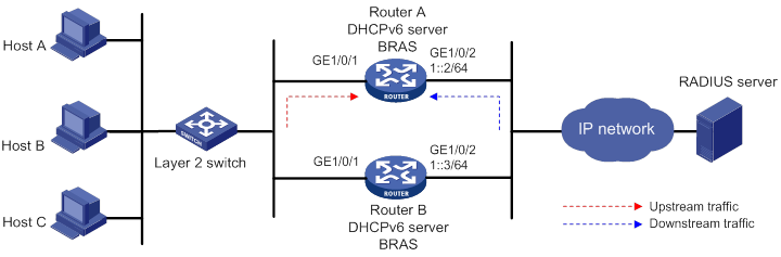
The subnet advertising on the master device takes effect if the DHCPv6 address pool is bound to a VSRP instance. If the address pool is applied to a VPN instance, the VPN instance must exist.
To configure the subnet advertisement feature:
|
Step |
Command |
Remarks |
|
1. Enter system view. |
system-view |
N/A |
|
2. Create an address pool and enter its view. |
ipv6 dhcp pool pool-name |
By default, no DHCPv6 address pools exist. |
|
3. Advertise the subnet assigned to DHCPv6 clients. |
network { prefix/prefix-length | prefix prefix-number [ sub-prefix/sub-prefix-length ] } [ preferred-lifetime preferred-lifetime valid-lifetime valid-lifetime ] export-route |
By default, the subnet assigned to DHCPv6 clients is not advertised. |
Applying a DHCPv6 address pool to a VPN instance
If a DHCPv6 address pool is applied to a VPN instance, the DHCPv6 server assigns IPv6 addresses in this address pool to clients in the VPN instance. Addresses in this address pool will not be assigned to clients on the public network.
The DHCPv6 server can obtain the VPN instance to which a DHCPv6 client belongs from the following information:
· The client's VPN information stored in authentication modules, such as IPoE.
· The VPN information of the DHCPv6 server's interface that receives DHCPv6 packets from the client.
The VPN information from authentication modules takes priority over the VPN information of the receiving interface.
To apply a DHCPv6 address pool to a VPN instance:
|
Step |
Command |
Remarks |
|
1. Enter system view. |
system-view |
N/A |
|
2. Create an address pool and enter its view. |
ipv6 dhcp pool pool-name |
By default, no DHCPv6 address pools exist. |
|
3. Apply the address pool to a VPN instance. |
vpn-instance vpn-instance-name |
By default, the address pool is not applied to any VPN instance. |
Enabling DHCPv6 logging on the DHCPv6 server
The DHCPv6 logging feature enables the DHCPv6 server to generate DHCPv6 logs and send them to the information center. For information about the log destination and output rule configuration in the information center, see Network Management and Monitoring Configuration Guide.
As a best practice, disable this feature if the log generation affects the device performance or reduces the address and prefix allocation efficiency. For example, this situation might occur when a large number of clients frequently come online or go offline.
To configure DHCPv6 logging on the DHCPv6 server:
|
Step |
Command |
Remarks |
|
1. Enter system view. |
system-view |
N/A |
|
2. Enable DHCPv6 logging. |
ipv6 dhcp log enable |
By default, DHCPv6 logging is disabled. |
Displaying and maintaining the DHCPv6 server
Execute display commands in any view and reset commands in user view.
|
Task |
Command |
|
Display the DUID of the local device. |
display ipv6 dhcp duid |
|
Display information about a DHCPv6 option group. |
display ipv6 dhcp option-group [ option-group-number ] |
|
Display DHCPv6 address pool information. |
display ipv6 dhcp pool [ pool-name | vpn-instance vpn-instance-name ] |
|
Display prefix pool information. |
display ipv6 dhcp prefix-pool [ prefix-pool-number ] [ vpn-instance vpn-instance-name ] |
|
Display DHCPv6 server information on an interface. |
display ipv6 dhcp server [ interface interface-type interface-number ] |
|
Display information about IPv6 address conflicts. |
display ipv6 dhcp server conflict [ address ipv6-address ] [ vpn-instance vpn-instance-name ] |
|
Display information about DHCPv6 binding auto backup |
display ipv6 dhcp server database |
|
Display information about expired IPv6 addresses. |
display ipv6 dhcp server expired [ [ address ipv6-address ] [ vpn-instance vpn-instance-name ] | pool pool-name ] |
|
Display information about IPv6 address bindings. |
display ipv6 dhcp server ip-in-use [ [ address ipv6-address ] [ vpn-instance vpn-instance-name ] | pool pool-name ] |
|
Display information about IPv6 prefix bindings. |
display ipv6 dhcp server pd-in-use [ pool pool-name | [ prefix prefix/prefix-len ] [ vpn-instance vpn-instance-name ] ] |
|
Display packet statistics on the DHCPv6 server. |
display ipv6 dhcp server statistics [ pool pool-name | vpn-instance vpn-instance-name ] |
|
Clear information about IPv6 address conflicts. |
reset ipv6 dhcp server conflict [ address ipv6-address ] [ vpn-instance vpn-instance-name ] |
|
Clear information about expired IPv6 address bindings. |
reset ipv6 dhcp server expired [ [ address ipv6-address ] [ vpn-instance vpn-instance-name ] | pool pool-name ] |
|
Clear information about IPv6 address bindings. |
reset ipv6 dhcp server ip-in-use [ [ address ipv6-address ] [ vpn-instance vpn-instance-name ] | pool pool-name ] |
|
Clear information about IPv6 prefix bindings. |
reset ipv6 dhcp server pd-in-use [ pool pool-name | [ prefix prefix/prefix-len ] [ vpn-instance vpn-instance-name ] ] |
|
Clear packets statistics on the DHCPv6 server. |
reset ipv6 dhcp server statistics [ vpn-instance vpn-instance-name ] |
DHCPv6 server configuration examples
Dynamic IPv6 prefix assignment configuration example
Network requirements
As shown in Figure 106, the router acts as a DHCPv6 server to assign an IPv6 prefix, a DNS server address, a domain name, a SIP server address, and a SIP server name to each DHCPv6 client.
The router assigns prefix 2001:0410:0201::/48 to the client whose DUID is 00030001CA0006A40000, and assigns prefixes in the range of 2001:0410::/48 to 2001:0410:FFFF::/48 (excluding 2001:0410:0201::/48) to other clients. The DNS server address is 2::2:3. The DHCPv6 clients reside in the domain aaa.com. The SIP server address is 2:2::4, and the SIP server name is bbb.com.
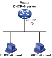
Configuration procedure
# Specify an IPv6 address for GigabitEthernet 1/0/1.
<Router> system-view
[Router] interface gigabitethernet 1/0/1
[Router-GigabitEthernet1/0/1] ipv6 address 1::1/64
# Disable RA message suppression on GigabitEthernet 1/0/1.
[Router-GigabitEthernet1/0/1] undo ipv6 nd ra halt
# Set the M flag to 1 in RA advertisements to be sent on GigabitEthernet 1/0/1. Hosts that receive the advertisements will obtain IPv6 addresses through DHCPv6.
[Router-GigabitEthernet1/0/1] ipv6 nd autoconfig managed-address-flag
# Set the O flag to 1 in RA advertisements to be sent on GigabitEthernet 1/0/1. Hosts that receive the advertisements will obtain information other than IPv6 address through DHCPv6.
[Router-GigabitEthernet1/0/1] ipv6 nd autoconfig other-flag
[Router-GigabitEthernet1/0/1] quit
# Create prefix pool 1, and specify the prefix 2001:0410::/32 with assigned prefix length 48.
[Router] ipv6 dhcp prefix-pool 1 prefix 2001:0410::/32 assign-len 48
# Create address pool 1.
[Router] ipv6 dhcp pool 1
# In address pool 1, specify subnet 1::/64 where the server interface resides.
[Router-dhcp6-pool-1] network 1::/64
# Apply prefix pool 1 to address pool 1, and set the preferred lifetime to one day, and the valid lifetime to three days.
[Router-dhcp6-pool-1] prefix-pool 1 preferred-lifetime 86400 valid-lifetime 259200
# In address pool 1, bind prefix 2001:0410:0201::/48 to the client DUID 00030001CA0006A40000, and set the preferred lifetime to one day, and the valid lifetime to three days.
[Router-dhcp6-pool-1] static-bind prefix 2001:0410:0201::/48 duid 00030001CA0006A40000 preferred-lifetime 86400 valid-lifetime 259200
# Configure the DNS server address as 2:2::3.
[Router-dhcp6-pool-1] dns-server 2:2::3
# Configure the domain name as aaa.com.
[Router-dhcp6-pool-1] domain-name aaa.com
# Configure the SIP server address as 2:2::4, and the SIP server name as bbb.com.
[Router-dhcp6-pool-1] sip-server address 2:2::4
[Router-dhcp6-pool-1] sip-server domain-name bbb.com
[Router-dhcp6-pool-1] quit
# Enable the DHCPv6 server on interface GigabitEthernet 1/0/1, enable desired prefix assignment and rapid prefix assignment, and set the preference to the highest.
[Router] interface gigabitethernet 1/0/1
[Router-GigabitEthernet1/0/1] ipv6 dhcp select server
[Router-GigabitEthernet1/0/1] ipv6 dhcp server allow-hint preference 255 rapid-commit
Verifying the configuration
# Display the DHCPv6 server configuration on GigabitEthernet 1/0/1.
[Router-GigabitEthernet1/0/1] display ipv6 dhcp server interface gigabitethernet 1/0/1
Using pool: global
Preference value: 255
Allow-hint: Enabled
Rapid-commit: Enabled
# Display information about address pool 1.
[Router-GigabitEthernet1/0/1] display ipv6 dhcp pool 1
DHCPv6 pool: 1
Network: 1::/64
Preferred lifetime 604800, valid lifetime 2592000
Prefix pool: 1
Preferred lifetime 86400, valid lifetime 259200
Static bindings:
DUID: 00030001CA0006A40000
IAID: Not configured
Prefix: 2001:410:201::/48
Preferred lifetime 86400, valid lifetime 259200
DNS server addresses:
2:2::3
Domain name:
aaa.com
SIP server addresses:
2:2::4
SIP server domain names:
bbb.com
# Display information about prefix pool 1.
[Router-GigabitEthernet1/0/1] display ipv6 dhcp prefix-pool 1
Prefix: 2001:410::/32
Assigned length: 48
Total prefix number: 65536
Available: 65535
In-use: 0
Static: 1
# After the client with the DUID 00030001CA0006A40000 obtains an IPv6 prefix, display the binding information on the DHCPv6 server.
[Router-GigabitEthernet1/0/1] display ipv6 dhcp server pd-in-use
Pool: 1
IPv6 prefix Type Lease expiration
2001:410:201::/48 Static(C) Jul 10 19:45:01 2009
# After the other client obtains an IPv6 prefix, display the binding information on the DHCPv6 server.
[Router-GigabitEthernet1/0/1] display ipv6 dhcp server pd-in-use
Pool: 1
IPv6 prefix Type Lease expiration
2001:410:201::/48 Static(C) Jul 10 19:45:01 2009
2001:410::/48 Auto(C) Jul 10 20:44:05 2009
Dynamic IPv6 address assignment configuration example
Network requirements
As shown in Figure 107, Router A acts as a DHCPv6 server to assign IPv6 addresses to the clients on subnets 1::1:0:0:0/96 and 1::2:0:0:0/96.
On Router A, configure the IPv6 address 1::1:0:0:1/96 for GigabitEthernet 1/0/1 and 1::2:0:0:1/96 for GigabitEthernet 1/0/2. The lease duration of the addresses on subnet 1::1:0:0:0/96 is 172800 seconds (two days), the valid time is 345600 seconds (four days), the domain name is aabbcc.com, and the DNS server address is 1::1:0:0:2/96. The lease duration of the addresses on subnet 1::2:0:0:0/96 is 432000 seconds (five days), the valid time is 864000 seconds (ten days), the domain name is aabbcc.com, and the DNS server address is 1::2:0:0:2/96.
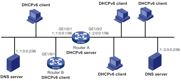
Configuration procedure
1. Configure the interfaces on the DHCPv6 server:
# Specify an IPv6 address for GigabitEthernet 1/0/1.
<RouterA> system-view
[RouterA] interface gigabitethernet 1/0/1
[RouterA-GigabitEthernet1/0/1] ipv6 address 1::1:0:0:1/96
# Disable RA message suppression on GigabitEthernet 1/0/1.
[RouterA-GigabitEthernet1/0/1] undo ipv6 nd ra halt
# Set the M flag to 1 in RA advertisements to be sent on GigabitEthernet 1/0/1. Hosts that receive the advertisements will obtain IPv6 addresses through DHCPv6.
[RouterA-GigabitEthernet1/0/1] ipv6 nd autoconfig managed-address-flag
# Set the O flag to 1 in RA advertisements to be sent on GigabitEthernet 1/0/1. Hosts that receive the advertisements will obtain information other than IPv6 address through DHCPv6.
[RouterA-GigabitEthernet1/0/1] ipv6 nd autoconfig other-flag
[RouterA-GigabitEthernet1/0/1] quit
# Specify an IPv6 address for GigabitEthernet 1/0/2.
[RouterA] interface gigabitethernet 1/0/2
[RouterA-GigabitEthernet1/0/2] ipv6 address 1::2:0:0:1/96
# Disable RA message suppression on GigabitEthernet 1/0/2.
[RouterA-GigabitEthernet1/0/2] undo ipv6 nd ra halt
# Set the M flag to 1 in RA advertisements to be sent on GigabitEthernet 1/0/2. Hosts that receive the advertisements will obtain IPv6 addresses through DHCPv6.
[RouterA-GigabitEthernet1/0/2] ipv6 nd autoconfig managed-address-flag
# Set the O flag to 1 in RA advertisements to be sent on GigabitEthernet 1/0/2. Hosts that receive the advertisements will obtain information other than IPv6 address through DHCPv6.
[RouterA-GigabitEthernet1/0/2] ipv6 nd autoconfig other-flag
[RouterA-GigabitEthernet1/0/2] quit
2. Enable DHCPv6:
# Enable the DHCPv6 server on the interfaces GigabitEthernet 1/0/1 and GigabitEthernet 1/0/2.
[RouterA] interface gigabitethernet 1/0/1
[RouterA-GigabitEthernet1/0/1] ipv6 dhcp select server
[RouterA-GigabitEthernet1/0/1] quit
[RouterA] interface gigabitethernet 1/0/2
[RouterA-GigabitEthernet1/0/2] ipv6 dhcp select server
[RouterA-GigabitEthernet1/0/2] quit
# Exclude the DNS server address from dynamic assignment.
[RouterA] ipv6 dhcp server forbidden-address 1::1:0:0:2
[RouterA] ipv6 dhcp server forbidden-address 1::2:0:0:2
# Create DHCPv6 address pool 1 to assign IPv6 addresses and other configuration parameters to clients on subnet 1::1:0:0:0/96.
[RouterA] ipv6 dhcp pool 1
[RouterA-dhcp6-pool-1] network 1::1:0:0:0/96 preferred-lifetime 172800 valid-lifetime 345600
[RouterA-dhcp6-pool-1] domain-name aabbcc.com
[RouterA-dhcp6-pool-1] dns-server 1::1:0:0:2
[RouterA-dhcp6-pool-1] quit
# Create DHCPv6 address pool 2 to assign IPv6 addresses and other configuration parameters to clients on subnet 1::2:0:0:0/96.
[RouterA] ipv6 dhcp pool 2
[RouterA-dhcp6-pool-2] network 1::2:0:0:0/96 preferred-lifetime 432000 valid-lifetime 864000
[RouterA-dhcp6-pool-2] domain-name aabbcc.com
[RouterA-dhcp6-pool-2] dns-server 1::2:0:0:2
[RouterA-dhcp6-pool-2] quit
Verifying the configuration
# Verify that clients on subnets 1::1:0:0:0/96 and 1::2:0:0:0/96 can obtain IPv6 addresses and all other configuration parameters from the DHCPv6 server (Router A). (Details not shown.)
# On the DHCPv6 server, display IPv6 addresses assigned to the clients.
[RouterA] display ipv6 dhcp server ip-in-use
Configuring the DHCPv6 relay agent
Overview
A DHCPv6 client usually uses a multicast address to contact the DHCPv6 server on the local link to obtain an IPv6 address and other configuration parameters. As shown in Figure 108, if the DHCPv6 server resides on another subnet, the DHCPv6 clients need a DHCPv6 relay agent to contact the server. The relay agent feature avoids deploying a DHCP server on each subnet.
Figure 108 Typical DHCPv6 relay agent application
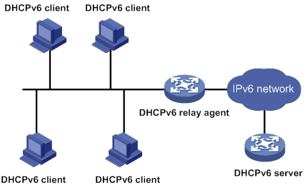
As shown in Figure 109, a DHCPv6 client obtains an IPv6 address and other network configuration parameters from a DHCPv6 server through a DHCPv6 relay agent. The following example uses rapid assignment to describe the process:
· The DHCPv6 client sends a Solicit message containing the Rapid Commit option to the multicast address FF02::1:2 of all the DHCPv6 servers and relay agents.
· After receiving the Solicit message, the DHCPv6 relay agent encapsulates the message into the Relay Message option of a Relay-forward message, and sends the message to the DHCPv6 server.
· After obtaining the Solicit message from the Relay-forward message, the DHCPv6 server performs the following tasks:
? Selects an IPv6 address and other required parameters.
? Adds them to a reply that is encapsulated within the Relay Message option of a Relay-reply message.
? Sends the Relay-reply message to the DHCPv6 relay agent.
· The DHCPv6 relay agent obtains the reply from the Relay-reply message and sends the reply to the DHCPv6 client.
· The DHCPv6 client uses the IPv6 address and other network parameters assigned by the DHCPv6 server to complete network configuration.
Figure 109 Operating process of a DHCPv6 relay agent
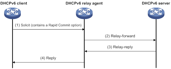
Compatibility information
Feature and hardware compatibility
DHCPv6 features are not supported on the following routers:
· MSR810/810-W/810-W-DB/810-LM/810-W-LM/810-10-PoE/810-LM-HK/810-W-LM-HK/810-LMS/810-LUS.
· MSR3600-28-SI/3600-51-SI.
Command and hardware compatibility
Commands and descriptions for centralized devices apply to the following routers:
· MSR810/810-W/810-W-DB/810-LM/810-W-LM/810-10-PoE/810-LM-HK/810-W-LM-HK/810-LMS/810-LUS.
· MSR2600-6-X1/2600-10-X1.
· MSR 2630.
· MSR3600-28/3600-51.
· MSR3600-28-SI/3600-51-SI.
· MSR3610-X1/3610-X1-DP/3610-X1-DC/3610-X1-DP-DC.
· MSR 3610/3620/3620-DP/3640/3660.
Commands and descriptions for distributed devices apply to the following routers:
· MSR5620.
· MSR 5660.
· MSR 5680.
DHCPv6 relay agent configuration task list
|
Tasks at a glance |
|
(Required.) Enabling the DHCPv6 relay agent on an interface |
|
(Required.) Specifying DHCPv6 servers on the relay agent |
|
(Optional.) Setting the DSCP value for DHCPv6 packets sent by the DHCPv6 relay agent |
|
(Optional.) Specifying a padding mode for the Interface-ID option |
|
(Optional.) Configuring a DHCPv6 relay address pool |
|
(Optional.) Specifying a gateway address for DHCPv6 clients |
Enabling the DHCPv6 relay agent on an interface
|
Step |
Command |
Remarks |
|
1. Enter system view. |
system-view |
N/A |
|
2. Enter interface view. |
interface interface-type interface-number |
N/A |
|
3. Enable DHCPv6 relay agent on the interface. |
ipv6 dhcp select relay |
By default, the DHCPv6 relay agent is disabled on the interface. Do not enable the DHCPv6 relay agent and DHCPv6 client on the same interface. |
Specifying DHCPv6 servers on the relay agent
You can use the ipv6 dhcp relay server-address command to specify a maximum of eight DHCPv6 servers on the DHCP relay agent interface. The DHCPv6 relay agent forwards DHCP requests to all the specified DHCPv6 servers.
To specify a DHCPv6 server on a relay agent:
|
Step |
Command |
Remarks |
|
1. Enter system view. |
system-view |
N/A |
|
2. Enter interface view. |
interface interface-type interface-number |
N/A |
|
3. Specify a DHCPv6 server. |
ipv6 dhcp relay server-address ipv6-address [ interface interface-type interface-number ] |
By default, no DHCPv6 server is specified. If a DHCPv6 server address is a link-local address or multicast address, you must specify an outgoing interface by using the interface keyword in this command. Otherwise, DHCPv6 packets might fail to reach the DHCPv6 server. |
Setting the DSCP value for DHCPv6 packets sent by the DHCPv6 relay agent
The DSCP value of a packet specifies the priority level of the packet and affects the transmission priority of the packet.
To set the DSCP value for DHCPv6 packets sent by the DHCPv6 relay agent:
|
Step |
Command |
Remarks |
|
1. Enter system view. |
system-view |
N/A |
|
2. Set the DSCP value for DHCPv6 packets sent by the DHCPv6 relay agent. |
ipv6 dhcp dscp dscp-value |
The default DSCP value is 56. |
Specifying a padding mode for the Interface-ID option
This feature enables the relay agent to fill the Interface-ID option in the specified mode. When receiving a DHCPv6 packet from a client, the relay agent fills the Interface-ID option in the mode and then forwards the packet to the DHCPv6 server.
To specify a padding mode for the Interface-ID option:
|
Step |
Command |
Remarks |
|
1. Enter system view. |
system-view |
N/A |
|
2. Enter interface view. |
interface interface-type interface-number |
N/A |
|
3. Specify a padding mode for the Interface-ID option. |
ipv6 dhcp relay interface-id { bas | interface } |
By default, the relay agent fills the Interface-ID option with the interface index of the interface. |
Configuring a DHCPv6 relay address pool
This feature allows DHCPv6 clients of the same type to obtain IPv6 addresses and other configuration parameters from the DHCPv6 servers specified in the matching relay address pool.
It applies to scenarios where the DHCPv6 relay agent connects to clients of the same access type but classified into different types by their locations. In this case, the relay interface typically has no IPv6 address configured. You can use the gateway-list command to specify the gateway address for clients matching the same relay address pool.
Upon receiving a DHCPv6 Solicit or Request from a client that matches a relay address pool, the relay agent processes the packet as follows:
· Fills the link-address field of the packet with the specified gateway address.
· Forwards the packet to all DHCPv6 servers in the matching relay address pool.
The DHCPv6 servers select an address pool according to the gateway address.
To configure a DHCPv6 relay address pool:
|
Step |
Command |
Remarks |
|
1. Enter system view. |
system-view |
N/A |
|
2. Create a DHCPv6 relay address pool and enter its view. |
ipv6 dhcp pool pool-name |
By default, no DHCPv6 relay address pools exist. This command is the same for creating DHCPv6 address pools on a DHCPv6 server. However, the relay address pool name is not necessarily the same as the server address pool name. |
|
3. Specify gateway addresses for the clients matching the relay address pool. |
gateway-list ipv6-address&<1-8> |
By default, no gateway address is specified. You can specify a maximum of eight gateway addresses, but only the first one takes effect. |
|
4. Specify DHCPv6 servers for the relay address pool. |
remote-server ipv6-address [ interface interface-type interface-number ] |
By default, no DHCPv6 server is specified for the relay address pool. You can specify a maximum of eight DHCPv6 servers for one relay address pool for high availability. The relay agent forwards DHCPv6 Solicit and Request packets to all DHCPv6 servers in the relay address pool. |
Specifying a gateway address for DHCPv6 clients
By default, the DHCPv6 relay agent fills the link-address field of DHCPv6 Solicit and Request packets with the first IPv6 address of the relay interface. You can specify a gateway address on the relay agent for DHCPv6 clients. The DHCPv6 relay agent uses the specified gateway address to fill the link-address field of DHCPv6 Solicit and Request packets.
To specify a gateway address for DHCPv6 clients:
|
Step |
Command |
Remarks |
|
1. Enter system view. |
system-view |
N/A |
|
2. Enter interface view. |
interface interface-type interface-number |
N/A |
|
3. Specify a gateway address for DHCPv6 clients. |
ipv6 dhcp relay gateway ipv6-address |
By default, the DHCPv6 relay agent uses the first IPv6 address of the relay interface as the clients' gateway address. |
Displaying and maintaining the DHCPv6 relay agent
Execute display commands in any view and reset commands in user view.
|
Task |
Command |
|
Display the DUID of the local device. |
display ipv6 dhcp duid |
|
Display DHCPv6 server addresses specified on the DHCPv6 relay agent. |
display ipv6 dhcp relay server-address [ interface interface-type interface-number ] |
|
Display packet statistics on the DHCPv6 relay agent. |
display ipv6 dhcp relay statistics [ interface interface-type interface-number ] |
|
Clear packets statistics on the DHCPv6 relay agent. |
reset ipv6 dhcp relay statistics [ interface interface-type interface-number ] |
DHCPv6 relay agent configuration example
Network requirements
As shown in Figure 110, configure the DHCPv6 relay agent on Router A to relay DHCP packets between DHCPv6 clients and the DHCPv6 server.
Router A acts as the gateway of network 1::/64. It sends RA messages to notify the hosts to obtain IPv6 addresses and other configuration parameters through DHCPv6. For more information about RA messages, see "Configuring basic IPv6 settings."
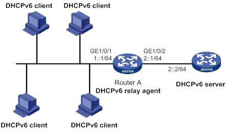
Configuration procedure
# Specify IPv6 addresses for GigabitEthernet 1/0/1 and GigabitEthernet 1/0/2.
<RouterA> system-view
[RouterA] interface gigabitethernet 1/0/2
[RouterA-GigabitEthernet1/0/2] ipv6 address 2::1 64
[RouterA-GigabitEthernet1/0/2] quit
[RouterA] interface gigabitethernet 1/0/1
[RouterA-GigabitEthernet1/0/1] ipv6 address 1::1 64
# Disable RA message suppression on GigabitEthernet 1/0/1.
[RouterA-GigabitEthernet1/0/1] undo ipv6 nd ra halt
# Set the M flag to 1 in RA advertisements to be sent on GigabitEthernet 1/0/1. Hosts that receive the RA messages will obtain IPv6 addresses through DHCPv6.
[RouterA-GigabitEthernet1/0/1] ipv6 nd autoconfig managed-address-flag
# Set the O flag to 1 in RA advertisements to be sent on GigabitEthernet 1/0/1. Hosts that receive the RA messages will obtain information other than IPv6 address through DHCPv6.
[RouterA-GigabitEthernet1/0/1] ipv6 nd autoconfig other-flag
# Enable the DHCPv6 relay agent on GigabitEthernet 1/0/1 and specify the DHCPv6 server on the relay agent.
[RouterA-GigabitEthernet1/0/1] ipv6 dhcp select relay
[RouterA-GigabitEthernet1/0/1] ipv6 dhcp relay server-address 2::2
Verifying the configuration
# Display DHCPv6 server address information on Router A.
[RouterA-GigabitEthernet1/0/1] display ipv6 dhcp relay server-address
Interface: GigabitEthernet1/0/1
Server address Outgoing Interface
2::2
# Display packet statistics on the DHCPv6 relay agent.
[RouterA-GigabitEthernet1/0/1] display ipv6 dhcp relay statistics
Packets dropped : 0
Packets received : 14
Solicit : 0
Request : 0
Confirm : 0
Renew : 0
Rebind : 0
Release : 0
Decline : 0
Information-request : 7
Relay-forward : 0
Relay-reply : 7
Packets sent : 14
Advertise : 0
Reconfigure : 0
Reply : 7
Relay-forward : 7
Relay-reply : 0
Configuring the DHCPv6 client
Overview
With DHCPv6 client configured, an interface can obtain configuration parameters from the DHCPv6 server.
A DHCPv6 client can use DHCPv6 to complete the following functions:
· Obtain an IPv6 address, an IPv6 prefix, or both, and obtain other configuration parameters. The client automatically creates a DHCPv6 option group for the obtained parameters. With the obtained IPv6 prefix, the client can generate its global unicast address.
· Support stateless DHCPv6 to obtain configuration parameters except IPv6 address and IPv6 prefix. The client obtains an IPv6 address through stateless IPv6 address autoconfiguration. If the client receives an RA message with the M flag set to 0 and the O flag set to 1 during address acquisition, stateless DHCPv6 starts.
Compatibility information
Feature and hardware compatibility
DHCPv6 features are not supported on the following routers:
· MSR810/810-W/810-W-DB/810-LM/810-W-LM/810-10-PoE/810-LM-HK/810-W-LM-HK/810-LMS/810-LUS.
· MSR3600-28-SI/3600-51-SI.
Command and hardware compatibility
Commands and descriptions for centralized devices apply to the following routers:
· MSR810/810-W/810-W-DB/810-LM/810-W-LM/810-10-PoE/810-LM-HK/810-W-LM-HK/810-LMS/810-LUS.
· MSR2600-6-X1/2600-10-X1.
· MSR 2630.
· MSR3600-28/3600-51.
· MSR3600-28-SI/3600-51-SI.
· MSR3610-X1/3610-X1-DP/3610-X1-DC/3610-X1-DP-DC.
· MSR 3610/3620/3620-DP/3640/3660.
Commands and descriptions for distributed devices apply to the following routers:
· MSR5620.
· MSR 5660.
· MSR 5680.
Configuration restrictions and guidelines
When you configure DHCPv6 client, follow these restrictions and guidelines:
· The DHCPv6 client configuration is supported only on Layer 3 Ethernet interfaces, Layer 3 aggregate interfaces, and VLAN interfaces.
· Do not configure the DHCPv6 client on the same interface as the DHCPv6 server or the DHCPv6 relay agent.
DHCPv6 client configuration task list
|
Tasks at a glance |
|
(Required.) Perform one of the following tasks: · Configuring IPv6 address acquisition · Configuring IPv6 prefix acquisition |
|
(Optional.) Configuring the DHCPv6 client DUID |
|
(Optional.) Setting the DSCP value for DHCPv6 packets sent by the DHCPv6 client |
Configuring IPv6 address acquisition
|
Step |
Command |
Remarks |
|
1. Enter system view. |
system-view |
N/A |
|
2. Enter interface view. |
interface interface-type interface-number |
Supported interfaces include Layer 3 Ethernet interface, Layer 3 Ethernet subinterface, Layer 3 aggregate interface, Layer 3 aggregate subinterface, and VLAN interface. |
|
3. Configure the interface to use DHCPv6 to obtain an IPv6 address and other configuration parameters. |
ipv6 address dhcp-alloc [ option-group group-number | rapid-commit ] * |
By default, the interface does not use DHCPv6 for IPv6 address acquisition. |
Configuring IPv6 prefix acquisition
|
Step |
Command |
Remarks |
|
1. Enter system view. |
system-view |
N/A |
|
2. Enter interface view. |
interface interface-type interface-number |
Supported interfaces include Layer 3 Ethernet interface, Layer 3 Ethernet subinterface, Layer 3 aggregate interface, Layer 3 aggregate subinterface, and VLAN interface. |
|
3. Configure the interface to use DHCPv6 to obtain an IPv6 prefix and other configuration parameters. |
ipv6 dhcp client pd prefix-number [ option-group group-number | rapid-commit ] * |
By default, the interface does not use DHCPv6 for IPv6 prefix acquisition. |
Configuring IPv6 address and prefix acquisition
|
Step |
Command |
Remarks |
|
1. Enter system view. |
system-view |
N/A |
|
2. Enter interface view. |
interface interface-type interface-number |
Supported interfaces include Layer 3 Ethernet interface, Layer 3 Ethernet subinterface, Layer 3 aggregate interface, Layer 3 aggregate subinterface, and VLAN interface. |
|
3. Configure the interface to use DHCPv6 to obtain an IPv6 address, an IPv6 prefix, and other configuration parameters. |
ipv6 dhcp client stateful prefix prefix-number [ option-group option-group-number | rapid-commit ] * |
By default, the interface does not use DHCPv6 for IPv6 address and prefix acquisition. |
Configuring stateless DHCPv6
|
Step |
Command |
Remarks |
|
1. Enter system view. |
system-view |
N/A |
|
2. Enter interface view. |
interface interface-type interface-number |
Supported interfaces include Layer 3 Ethernet interface, Layer 3 Ethernet subinterface, Layer 3 aggregate interface, Layer 3 aggregate subinterface, and VLAN interface. |
|
3. Configure the interface to support stateless DHCPv6. |
·
Enable stateless IPv6 address
autoconfiguration: ·
Enable stateless DHCPv6: |
By default, the interface does not support stateless DHCPv6. You can perform both tasks. If you use only the ipv6 address auto command, make sure the M flag is set to 0 and the O flag is set to 1 in the RA message. Otherwise, stateless DHCPv6 cannot be triggered. |
Configuring the DHCPv6 client DUID
The DUID of a DHCPv6 client is the globally unique identifier of the client. The client pads its DUID into Option 1 of the DHCPv6 packet that it sends to the DHCPv6 server. The DHCPv6 server can assign specific IPv6 addresses or prefixes to DHCPv6 clients with specific DUIDs.
To configure the DHCPv6 client DUID:
|
Step |
Command |
Remarks |
|
1. Enter system view. |
system-view |
N/A |
|
2. Enter interface view. |
interface interface-type interface-number |
Supported interfaces include Layer 3 Ethernet interface, Layer 3 Ethernet subinterface, Layer 3 aggregate interface, Layer 3 aggregate subinterface, and VLAN interface. |
|
3. Configure the DHCPv6 client DUID. |
ipv6 dhcp client duid { ascii string | hex string | mac interface-type interface-number } |
By default, the interface uses the device bridge MAC address to generate its DHCPv6 client DUID. Make sure the DUID that you configure is unique. |
Setting the DSCP value for DHCPv6 packets sent by the DHCPv6 client
The DSCP value of a packet specifies the priority level of the packet and affects the transmission priority of the packet.
To set the DSCP value for DHCPv6 packets sent by the DHCPv6 client:
|
Step |
Command |
Remarks |
|
1. Enter system view. |
system-view |
N/A |
|
2. Set the DSCP value for DHCPv6 packets sent by the DHCPv6 client. |
ipv6 dhcp client dscp dscp-value |
By default, the DSCP value in DHCPv6 packets sent by the DHCPv6 client is 56. |
Displaying and maintaining DHCPv6 client
Execute the display commands in any view, and execute the reset command in user view.
|
Task |
Command |
|
Display the DHCPv6 client information. |
display ipv6 dhcp client [ interface interface-type interface-number ] |
|
Display the DHCPv6 client statistics. |
display ipv6 dhcp client statistics [ interface interface-type interface-number ] |
|
Clear the DHCPv6 client statistics. |
reset ipv6 dhcp client statistics [ interface interface-type interface-number ] |
DHCPv6 client configuration examples
IPv6 address acquisition configuration example
Network requirements
As shown in Figure 111, configure GigabitEthernet 1/0/1 of the router to use DHCPv6 to obtain configuration parameters from the DHCPv6 server. The parameters include IPv6 address, DNS server address, domain name suffix, SIP server address, and SIP server domain name.
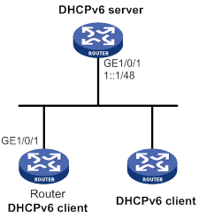
Configuration procedure
You must configure the DHCPv6 server before configuring the DHCPv6 client. For information about configuring the DHCPv6 server, see "Configuring the DHCPv6 server."
# Configure GigabitEthernet 1/0/1 to support DHCPv6 rapid address assignment. Enable the DHCPv6 client to create dynamic DHCPv6 option group 1 for saving configuration parameters.
<Router> system-view
[Router] interface gigabitethernet 1/0/1
[Router-GigabitEthernet1/0/1] ipv6 address dhcp-alloc rapid-commit option-group 1
[Router-GigabitEthernet1/0/1] quit
Verifying the configuration
# Verify that the DHCPv6 client has obtained configuration parameters from the server.
[Router] display ipv6 dhcp client
GigabitEthernet1/0/1:
Type: Stateful client requesting address
State: OPEN
Client DUID: 00030001d07e28db74fb
Preferred server:
Reachable via address: FE80::2E0:1FF:FE00:19
Server DUID: 00030001000fe20a0a00
IA_NA: IAID 0x00000a02, T1 50 sec, T2 80 sec
Address: 1:2::2/128
Preferred lifetime 100 sec, valid lifetime 200 sec
Will expire on Mar 27 2014 at 15:35:55 (196 seconds left)
DNS server addresses:
2000::FF
Domain name:
example.com
SIP server addresses:
2:2::4
SIP server domain names:
bbb.com
# Verify that the client has created a dynamic DHCPv6 option group for saving configuration parameters.
[Router-GigabitEthernet1/0/1] display ipv6 dhcp option-group 1
DNS server addresses:
Type: Dynamic (DHCPv6 address allocation)
Interface: GigabitEthernet1/0/1
2000::FF
Domain name:
Type: Dynamic (DHCPv6 address allocation)
Interface: GigabitEthernet1/0/1
example.com
SIP server addresses:
Type: Dynamic (DHCPv6 address allocation)
Interface: GigabitEthernet1/0/1
2:2::4
SIP server domain names:
Type: Dynamic (DHCPv6 address allocation)
Interface: GigabitEthernet1/0/1
bbb.com
# Verify that the DHCPv6 client has obtained an IPv6 address.
[Router] display ipv6 interface brief
*down: administratively down
(s): spoofing
Interface Physical Protocol IPv6 Address
GigabitEthernet1/0/1 up up 1:1::2
IPv6 prefix acquisition configuration example
Network requirements
As shown in Figure 112, configure GigabitEthernet 1/0/1 of the router to use DHCPv6 to obtain configuration parameters from the DHCPv6 server. The parameters include IPv6 prefix, DNS server address, domain name suffix, SIP server address, and SIP server domain name.
Figure 112 Network requirements
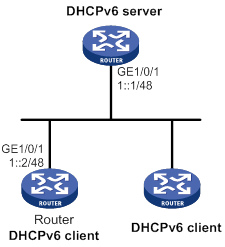
Configuration procedure
You must configure the DHCPv6 server before configuring the DHCPv6 client. For information about configuring the DHCPv6 server, see "Configuring the DHCPv6 server."
# Configure an IPv6 address for GigabitEthernet 1/0/1 that connects to the DHCPv6 server.
<Router> system-view
[Router] interface gigabitethernet 1/0/1
[Router-GigabitEthernet1/0/1] ipv6 address 1::2/48
# Configure GigabitEthernet 1/0/1 to support DHCPv6 rapid prefix assignment. Enable the DHCPv6 client to assign an ID to the obtained IPv6 prefix and create a dynamic DHCPv6 option group for saving configuration parameters.
[Router-GigabitEthernet1/0/1] ipv6 dhcp client pd 1 rapid-commit option-group 1
[Router-GigabitEthernet1/0/1] quit
Verifying the configuration
# Verify that the DHCPv6 client has obtained an IPv6 prefix and other configuration parameters from the DHCPv6 server.
[Router] display ipv6 dhcp client
GigabitEthernet1/0/1:
Type: Stateful client requesting prefix
State: OPEN
Client DUID: 00030001d07e28db74fb
Preferred server:
Reachable via address: FE80::2E0:1FF:FE00:19
Server DUID: 0003000100e001000000
IA_PD: IAID 0x00000a02, T1 50 sec, T2 80 sec
Prefix: 12:34::/48
Preferred lifetime 100 sec, valid lifetime 200 sec
Will expire on Feb 4 2014 at 15:37:20(80 seconds left)
DNS server addresses:
2000::FF
Domain name:
example.com
SIP server addresses:
2:2::4
SIP server domain names:
bbb.com
# Verify that the client has obtained an IPv6 prefix.
[Router] display ipv6 prefix 1
Number: 1
Type : Dynamic
Prefix: 12:34::/48
Preferred lifetime 100 sec, valid lifetime 200 sec
# Verify that the client has created a dynamic DHCPv6 option group for saving configuration parameters.
[Router] display ipv6 dhcp option-group 1
DNS server addresses
Type: Dynamic (DHCPv6 prefix allocation)
Interface: GigabitEthernet1/0/1
2000::FF
Domain name:
Type: Dynamic (DHCPv6 prefix allocation)
Interface: GigabitEthernet1/0/1
example.com
SIP server addresses:
Type: Dynamic (DHCPv6 prefix allocation)
Interface: GigabitEthernet1/0/1
2:2::4
SIP server domain names:
Type: Dynamic (DHCPv6 prefix allocation)
Interface: GigabitEthernet1/0/1
bbb.com
IPv6 address and prefix acquisition configuration example
Network requirements
As shown in Figure 113, configure GigabitEthernet 1/0/1 of the router to use DHCPv6 to obtain configuration parameters from the DHCPv6 server. The parameters include IPv6 address, IPv6 prefix, DNS server address, domain name suffix, SIP server address, and SIP server domain name.
Configuration procedure
You must configure the DHCPv6 server before configuring the DHCPv6 client. For information about configuring the DHCPv6 server, see "Configuring the DHCPv6 server."
# Configure an IPv6 address for GigabitEthernet 1/0/1 that connects to the DHCPv6 server.
<Router> system-view
[Router] interface gigabitethernet 1/0/1
[Router-GigabitEthernet1/0/1] ipv6 address 1::2/48
# Configure GigabitEthernet 1/0/1 to use DHCPv6 for IPv6 address and prefix acquisition. Specify IDs for the dynamic IPv6 prefix and dynamic DHCPv6 option group, and configure the client to support rapid address and prefix assignment.
[Router-GigabitEthernet1/0/1] ipv6 dhcp client stateful prefix 1 rapid-commit option-group 1
[Router-GigabitEthernet1/0/1] quit
Verifying the configuration
# Display DHCPv6 client information. The output shows that the DHCPv6 client has obtained an IPv6 address, an IPv6 prefix, and other configuration parameters from the DHCPv6 server.
[Router] display ipv6 dhcp client
GigabitEthernet1/0/1:
Type: Stateful client requesting address and prefix
State: OPEN
Client DUID: 00030001d07e28db74fb
Preferred server:
Reachable via address: FE80::2E0:1FF:FE00:19
Server DUID: 0003000100e001000000
IA_NA: IAID 0x00000a02, T1 50 sec, T2 80 sec
Address: 1:1::2/128
Preferred lifetime 100 sec, valid lifetime 200 sec
Will expire on Mar 27 2014 at 15:29:34 (198 seconds left)
IA_PD: IAID 0x00000a02, T1 50 sec, T2 80 sec
Prefix: 12:34::/48
Preferred lifetime 100 sec, valid lifetime 200 sec
Will expire on Mar 27 2014 at 15:29:34 (198 seconds left)
DNS server addresses:
2000::FF
Domain name:
example.com
SIP server addresses:
2:2::4
SIP server domain names:
bbb.com
# Display brief IPv6 information for all interfaces on the device. The output shows that the DHCPv6 client has obtained an IPv6 address.
[Router] display ipv6 interface brief
*down: administratively down
(s): spoofing
Interface Physical Protocol IPv6 Address
GigabitEthernet1/0/1 up up 1:1::2
# Display information about the dynamic IPv6 prefix. The output shows that the client has obtained an IPv6 prefix.
[Router] display ipv6 prefix 1
Number: 1
Type : Dynamic
Prefix: 12:34::/48
Preferred lifetime 100 sec, valid lifetime 200 sec
# Display information about the dynamic DHCPv6 option group. The output shows that the client has created a dynamic DHCPv6 option group for saving configuration parameters.
[Router] display ipv6 dhcp option-group 1
DHCPv6 option group: 1
DNS server addresses:
Type: Dynamic (DHCPv6 address and prefix allocation)
Interface: GigabitEthernet1/0/1
2000::FF
Domain name:
Type: Dynamic (DHCPv6 address and prefix allocation)
Interface: GigabitEthernet1/0/1
example.com
SIP server addresses:
Type: Dynamic (DHCPv6 address and prefix allocation)
Interface: GigabitEthernet1/0/1
2:2::4
SIP server domain names:
Type: Dynamic (DHCPv6 address and prefix allocation)
Interface: GigabitEthernet1/0/1
bbb.com
Stateless DHCPv6 configuration example
Network requirements
As shown in Figure 114, configure GigabitEthernet 1/0/1 on Router A to use stateless DHCPv6 to obtain configuration parameters except IPv6 address and IPv6 prefix. Router B acts as the gateway and advertises RA messages periodically.
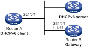
Configuration procedure
You must configure the DHCPv6 server before configuring the DHCPv6 client. For information about configuring the DHCPv6 server, see "Configuring the DHCPv6 server."
1. Configure the gateway Router B:
# Configure an IPv6 address for GigabitEthernet 1/0/1.
<RouterB> system-view
[RouterB] interface gigabitethernet 1/0/1
[RouterB-GigabitEthernet1/0/1] ipv6 address 1::1 64
# Set the O flag to 1 in RA advertisements to be sent on GigabitEthernet 1/0/1. Hosts that receive the RA advertisements will obtain information other than IPv6 address through DHCPv6.
[RouterB-GigabitEthernet1/0/1] ipv6 nd autoconfig other-flag
# Disable RA message suppression on GigabitEthernet 1/0/1.
[RouterB-GigabitEthernet1/0/1] undo ipv6 nd ra halt
2. Configure the DHCPv6 client on Router A:
# Enable stateless IPv6 address autoconfiguration on GigabitEthernet 1/0/1.
<RouterA> system-view
[RouterA] interface gigabitethernet 1/0/1
[RouterA-GigabitEthernet1/0/1] ipv6 address auto
With stateless IPv6 address autoconfiguration enabled, but no IPv6 address configured for GigabitEthernet 1/0/1, Router A generates a link local address. It sends an RS message to Router B to request configuration information for IPv6 address generation. Upon receiving the RS message, Router B sends back an RA message. After receiving an RA message with the M flag set to 0 and the O flag set to 1, Router A performs stateless DHCPv6 to get other configuration parameters.
Verifying the configuration
# Display DHCPv6 client information for GigabitEthernet 1/0/1.
[RouterA-GigabitEthernet1/0/1] display ipv6 dhcp client interface gigabitethernet 1/0/1
GigabitEthernet1/0/1:
Type: Stateless client
State: OPEN
Client DUID: 00030001000fe2ff0000
Preferred server:
Reachable via address: FE80::213:7FFF:FEF6:C818
Server DUID: 0003000100137ff6c818
DNS server addresses:
1:2:4::5
1:2:4::7
Domain name:
abc.com
# Display DHCPv6 client statistics.
[RouterA-GigabitEthernet1/0/1] display ipv6 dhcp client statistics
Interface : GigabitEthernet1/0/1
Packets received : 1
Reply : 1
Advertise : 0
Reconfigure : 0
Invalid : 0
Packets sent : 5
Solicit : 0
Request : 0
Renew : 0
Rebind : 0
Information-request : 5
Release : 0
Decline : 0
Configuring DHCPv6 snooping
Overview
DHCPv6 snooping works between the DHCPv6 client and server, or between the DHCPv6 client and DHCPv6 relay agent. It guarantees that DHCPv6 clients obtain IP addresses from authorized DHCPv6 servers. Also, it records IP-to-MAC bindings of DHCPv6 clients (called DHCPv6 snooping entries) for security purposes.
DHCPv6 snooping does not work between the DHCPv6 server and DHCPv6 relay agent.
DHCPv6 snooping defines trusted and untrusted ports to make sure that clients obtain IPv6 addresses only from authorized DHCPv6 servers.
· Trusted—A trusted port can forward DHCPv6 messages correctly to make sure the clients get IPv6 addresses from authorized DHCPv6 servers.
· Untrusted—An untrusted port discards received messages sent by DHCPv6 servers to prevent unauthorized servers from assigning IPv6 addresses.
DHCPv6 snooping reads DHCP-ACK messages received from trusted ports and DHCP-REQUEST messages to create DHCPv6 snooping entries. A DHCPv6 snooping entry includes the MAC and IP addresses of a client, the port that connects to the DHCPv6 client, and the VLAN. You can use the display ipv6 dhcp snooping binding command to display the IP addresses of users for management.
Application of trusted and untrusted ports
Configure ports facing the DHCPv6 server as trusted ports, and configure other ports as untrusted ports.
As shown in Figure 115, configure the DHCPv6 snooping device's port that is connected to the DHCPv6 server as a trusted port. The trusted port forwards response messages from the DHCPv6 server to the client. The untrusted port connected to the unauthorized DHCPv6 server discards incoming DHCPv6 response messages.
Figure 115 Trusted and untrusted ports
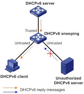
Compatibility information
Feature and hardware compatibility
DHCPv6 features are not supported on the following routers:
· MSR810/810-W/810-W-DB/810-LM/810-W-LM/810-10-PoE/810-LM-HK/810-W-LM-HK/810-LMS/810-LUS.
· MSR3600-28-SI/3600-51-SI.
Command and hardware compatibility
Commands and descriptions for centralized devices apply to the following routers:
· MSR810/810-W/810-W-DB/810-LM/810-W-LM/810-10-PoE/810-LM-HK/810-W-LM-HK/810-LMS/810-LUS.
· MSR2600-6-X1/2600-10-X1.
· MSR 2630.
· MSR3600-28/3600-51.
· MSR3600-28-SI/3600-51-SI.
· MSR3610-X1/3610-X1-DP/3610-X1-DC/3610-X1-DP-DC.
· MSR 3610/3620/3620-DP/3640/3660.
· MSR810-LM-GL/810-W-LM-GL/830-6EI-GL/830-10EI-GL/830-6HI-GL/830-10HI-GL/2600-6-X1-GL/3600-28-SI-GL.
Commands and descriptions for distributed devices apply to the following routers:
· MSR5620.
· MSR 5660.
· MSR 5680.
H3C implementation of Option 18 and Option 37
Option 18 for DHCPv6 snooping
Option 18, also called the interface-ID option, is used by the DHCPv6 relay agent to determine the interface to use to forward RELAY-REPLY message.
In H3C implementation, the DHCPv6 snooping device adds Option 18 to the received DHCPv6 request message before forwarding it to the DHCPv6 server. The server then assigns IP address to the client based on the client information in Option 18.
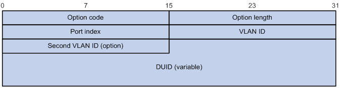
Figure 116 shows the Option 18 format, which includes the following fields:
· Option code—Option code.
· Option length—Size of the option data.
· Port index—Port that receives the DHCPv6 request from the client.
· VLAN ID—ID of the outer VLAN.
· Second VLAN ID—ID of the inner VLAN.
· DUID—DUID of the DHCPv6 client.
|
|
NOTE: The Second VLAN ID field is optional. If the received DHCPv6 request does not contain a second VLAN, Option 18 also does not contain it. |
DHCPv6 snooping support for Option 37
Option 37, also called the remote-ID option, is used to identify the client.
In H3C implementation, the DHCPv6 snooping device adds Option 37 to the received DHCPv6 request message before forwarding it to the DHCPv6 server. This option provides client information about address allocation.
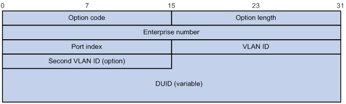
Figure 117 shows the Option 37 format, which includes the following fields:
· Option code—Option code.
· Option length—Size of the option data.
· Enterprise number—Enterprise number.
· Port index—Port that receives the DHCPv6 request from the client.
· VLAN ID—ID of the outer VLAN.
· Second VLAN ID—ID of the inner VLAN.
· DUID—DUID of the DHCPv6 client.
|
|
NOTE: The Second VLAN ID field is optional. If the received DHCPv6 request does not contain a second VLAN, Option 37 also does not contain it. |
DHCPv6 snooping configuration task list
|
Tasks at a glance |
|
(Required.) Configuring basic DHCPv6 snooping |
|
(Optional.) Configuring Option 18 and Option 37 |
|
(Optional.) Configuring DHCPv6 snooping entry auto backup |
|
(Optional.) Setting the maximum number of DHCPv6 snooping entries |
|
(Optional.) Enabling DHCPv6-REQUEST check |
|
(Optional.) Configuring a DHCPv6 packet blocking port |
|
(Optional.) Enabling DHCPv6 snooping logging |
Configuring basic DHCPv6 snooping
Follow these guidelines when you configure basic DHCPv6 snooping:
· To make sure DHCPv6 clients can obtain valid IPv6 addresses, specify the ports connected to authorized DHCPv6 servers as trusted ports. The trusted ports and the ports connected to DHCPv6 clients must be in the same VLAN.
· If you configure DHCPv6 snooping settings on a Layer 2 Ethernet interface that is a member port of a Layer 2 aggregate interface, the settings do not take effect unless the interface is removed from the aggregation group.
To configure basic DHCPv6 snooping:
|
Step |
Command |
Remarks |
|
1. Enter system view. |
system-view |
N/A |
|
2. Enable DHCPv6 snooping. |
ipv6 dhcp snooping enable |
By default, DHCPv6 snooping is disabled. |
|
3. Enter interface view. |
interface interface-type interface-number |
This interface must connect to the DHCPv6 server. |
|
4. Specify the port as a trusted port. |
ipv6 dhcp snooping trust |
By default, all ports are untrusted ports after DHCPv6 snooping is enabled. |
|
5. Return to system view. |
quit |
N/A |
|
6. Enter interface view. |
interface interface-type interface-number |
This interface must connect to the DHCPv6 client. |
|
7. (Optional.) Enable recording of client information in DHCPv6 snooping entries. |
ipv6 dhcp snooping binding record |
By default, DHCPv6 snooping does not record client information. |
Configuring Option 18 and Option 37
|
Step |
Command |
Remarks |
|
1. Enter system view. |
system-view |
N/A |
|
2. Enter interface view. |
interface interface-type interface-number |
N/A |
|
3. Enable support for Option 18. |
ipv6 dhcp snooping option interface-id enable |
By default, Option 18 is not supported. |
|
4. (Optional.) Specify the content as the interface ID. |
ipv6 dhcp snooping option interface-id [ vlan vlan-id ] string interface-id |
By default, the DHCPv6 snooping device uses its DUID as the content for Option 18. |
|
5. Enable support for Option 37. |
ipv6 dhcp snooping option remote-id enable |
By default, Option 37 is not supported. |
|
6. (Optional.) Specify the content as the remote ID. |
ipv6 dhcp snooping option remote-id [ vlan vlan-id ] string remote-id |
By default, the DHCPv6 snooping device uses its DUID as the content for Option 37. |
Configuring DHCPv6 snooping entry auto backup
The auto backup feature saves DHCPv6 snooping entries to a backup file, and allows the DHCPv6 snooping device to download the entries from the backup file at reboot. The entries on the DHCPv6 snooping device cannot survive a reboot. The auto backup helps the security features provide services if these features (such as IP source guard) must use DHCPv6 snooping entries for user authentication.
|
|
IMPORTANT: If you disable DHCPv6 snooping with the undo ipv6 dhcp snooping enable command, the device deletes all DHCPv6 snooping entries, including those stored in the backup file. |
To configure DHCPv6 snooping entry auto backup:
|
Step |
Command |
Remarks |
|
1. Enter system view. |
system-view |
N/A |
|
2. Configure the DHCPv6 snooping device to back up DHCPv6 snooping entries to a file. |
ipv6 dhcp snooping binding database filename { filename | url url [ username username [ password { cipher | simple } string ] ] } |
By default, the DHCPv6 snooping device does not back up the DHCPv6 snooping entries. With this command executed, the DHCPv6 snooping device backs up DHCPv6 snooping entries immediately and runs auto backup. This command automatically creates the file if you specify a non-existent file. |
|
3. (Optional.) Manually save DHCPv6 snooping entries to the backup file. |
ipv6 dhcp snooping binding database update now |
N/A |
|
4. (Optional.) Set the waiting time after a DHCPv6 snooping entry change for the DHCPv6 snooping device to update the backup file. |
ipv6 dhcp snooping binding database update interval interval |
The default waiting time is 300 seconds. The waiting period starts when a DHCPv6 snooping entry is learned, updated, or removed. The DHCPv6 snooping device updates the backup file when the specified waiting period is reached. All changed entries during the period will be saved to the backup file. If no DHCPv6 snooping entry changes, the backup file is not updated. |
Setting the maximum number of DHCPv6 snooping entries
Perform this task to prevent the system resources from being overused.
To set the maximum number of DHCPv6 snooping entries:
|
Step |
Command |
Remarks |
|
1. Enter system view. |
system-view |
N/A |
|
2. Enter interface view. |
interface interface-type interface-number |
N/A |
|
3. Set the maximum number of DHCPv6 snooping entries for the interface to learn. |
ipv6 dhcp snooping max-learning-num max-number |
By default, the number of DHCPv6 snooping entries for an interface to learn is not limited. |
Enabling DHCPv6-REQUEST check
Perform this task to use the DHCPv6-REQUEST check feature to protect the DHCPv6 server against DHCPv6 client spoofing attacks. Attackers can forge DHCPv6-RENEW messages to renew leases for legitimate DHCPv6 clients that no longer need the IP addresses. The forged messages disable the victim DHCPv6 server from releasing the IP addresses. Attackers can also forge DHCPv6-DECLINE or DHCPv6-RELEASE messages to terminate leases for legitimate DHCPv6 clients that still need the IP addresses.
The DHCPv6-REQUEST check feature enables the DHCPv6 snooping device to check every received DHCPv6-RENEW, DHCPv6-DECLINE, or DHCPv6-RELEASE message against DHCPv6 snooping entries.
· If any criterion in an entry is matched, the device compares the entry with the message information.
? If they are consistent, the device considers the message valid and forwards it to the DHCPv6 server.
? If they are different, the device considers the message forged and discards it.
· If no matching entry is found, the device forwards the message to the DHCPv6 server.
To enable DHCPv6-REQUEST check:
|
Step |
Command |
Remarks |
|
1. Enter system view. |
system-view |
N/A |
|
2. Enter interface view. |
interface interface-type interface-number |
N/A |
|
ipv6 dhcp snooping check request-message |
By default, DHCPv6-REQUEST check is disabled. You can enable the feature only on Layer 2 Ethernet interfaces and Layer 2 aggregate interfaces. |
Configuring a DHCPv6 packet blocking port
Perform this task to configure a port as a DHCPv6 packet blocking port. The DHCPv6 packet blocking port drops all incoming DHCP requests.
To configure a DHCPv6 packet blocking port:
|
Step |
Command |
Remarks |
|
1. Enter system view. |
system-view |
N/A |
|
2. Enter interface view. |
interface interface-type interface-number |
N/A |
|
3. Configure the port to block DHCPv6 requests. |
ipv6 dhcp snooping deny |
By default, the port does not block DHCPv6 requests. |
Enabling DHCPv6 snooping logging
The DHCPv6 snooping logging feature enables the DHCPv6 snooping device to generate DHCPv6 snooping logs and send them to the information center. For information about the log destination and output rule configuration in the information center, see Network Management and Monitoring Configuration Guide.
As a best practice, disable this feature if the log generation affects the device performance.
To enable DHCPv6 snooping logging:
|
Step |
Command |
Remarks |
|
1. Enter system view. |
system-view |
N/A |
|
2. Enable DHCPv6 snooping logging. |
ipv6 dhcp snooping log enable |
By default, DHCPv6 snooping logging is disabled. |
Displaying and maintaining DHCPv6 snooping
Execute display commands in any view, and reset commands in user view.
|
Task |
Command |
|
Display information about trusted ports. |
display ipv6 dhcp snooping trust |
|
Display DHCPv6 snooping entries. |
display ipv6 dhcp snooping binding [ address ipv6-address [ vlan vlan-id ] ] |
|
Display information about the file that stores DHCPv6 snooping entries. |
display ipv6 dhcp snooping binding database |
|
Display DHCPv6 packet statistics for DHCPv6 snooping (centralized devices in standalone mode). |
display ipv6 dhcp snooping packet statistics |
|
Display DHCPv6 packet statistics for DHCPv6 snooping (distributed devices in standalone mode/centralized devices in IRF mode). |
display ipv6 dhcp snooping packet statistics [ slot slot-number ] |
|
Display DHCPv6 packet statistics for DHCPv6 snooping (distributed devices in IRF mode). |
display ipv6 dhcp snooping packet statistics [ chassis chassis-number slot slot-number ] |
|
Clear DHCPv6 snooping entries. |
reset ipv6 dhcp snooping binding { all | address ipv6-address [ vlan vlan-id ] } |
|
Clear DHCPv6 packet statistics for DHCPv6 snooping (centralized devices in standalone mode). |
reset ipv6 dhcp snooping packet statistics |
|
Clear DHCPv6 packet statistics for DHCPv6 snooping (distributed devices in standalone mode/centralized devices in IRF mode). |
reset ipv6 dhcp snooping packet statistics [ slot slot-number ] |
|
Clear DHCPv6 packet statistics for DHCPv6 snooping (distributed devices in IRF mode). |
reset ipv6 dhcp snooping packet statistics [ chassis chassis-number slot slot-number ] |
DHCPv6 snooping configuration example
Network requirements
As shown in Figure 118, configure GigabitEthernet 1/0/1 connected to the DHCPv6 server as a trusted port. Enable DHCPv6 snooping to record client information in DHCPv6 snooping entries.
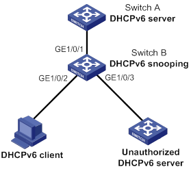
Configuration procedure
# Enable DHCPv6 snooping.
<SwitchB> system-view
[SwitchB] ipv6 dhcp snooping enable
# Specify GigabitEthernet 1/0/1 as a trusted port.
[SwitchB] interface gigabitethernet 1/0/1
[SwitchB-GigabitEthernet1/0/1] ipv6 dhcp snooping trust
[SwitchB-GigabitEthernet1/0/1] quit
# Enable recording of client information in DHCPv6 snooping entries.
[SwitchB]interface gigabitethernet 1/0/2
[SwitchB-GigabitEthernet1/0/2] ipv6 dhcp snooping binding record
[SwitchB-GigabitEthernet1/0/2] quit
Verifying the configuration
# Verify that the DHCPv6 client obtains an IPv6 address and all other configuration parameters only from the authorized DHCPv6 server. (Details not shown.)
# Display DHCPv6 snooping entries on the DHCPv6 snooping device.
[SwitchB] display ipv6 dhcp snooping binding
Configuring IPv6 fast forwarding
Overview
Fast forwarding reduces route lookup time and improves packet forwarding efficiency by using a high-speed cache and data-flow-based technology. It identifies a data flow by using the following fields:
· Source IPv6 address.
· Destination IPv6 address.
· Source port number.
· Destination port number.
· Protocol number.
After a flow's first packet is forwarded through the routing table, fast forwarding creates an entry and uses the entry to forward subsequent packets of the flow.
Compatibility information
Feature and hardware compatibility
IPv6-related features are not supported on the following routers:
· MSR810/810-W/810-W-DB/810-LM/810-W-LM/810-10-PoE/810-LM-HK/810-W-LM-HK/810-LMS/810-LUS.
· MSR3600-28-SI/3600-51-SI.
Command and hardware compatibility
Commands and descriptions for centralized devices apply to the following routers:
· MSR810/810-W/810-W-DB/810-LM/810-W-LM/810-10-PoE/810-LM-HK/810-W-LM-HK/810-LMS/810-LUS.
· MSR2600-6-X1/2600-10-X1.
· MSR 2630.
· MSR3600-28/3600-51.
· MSR3600-28-SI/3600-51-SI.
· MSR3610-X1/3610-X1-DP/3610-X1-DC/3610-X1-DP-DC.
· MSR 3610/3620/3620-DP/3640/3660.
· MSR810-LM-GL/810-W-LM-GL/830-6EI-GL/830-10EI-GL/830-6HI-GL/830-10HI-GL/2600-6-X1-GL/3600-28-SI-GL.
Commands and descriptions for distributed devices apply to the following routers:
· MSR5620.
· MSR 5660.
· MSR 5680.
Configuring the aging time for IPv6 fast forwarding entries
The IPv6 fast forwarding table uses an aging timer for each forwarding entry. If an entry is not updated before the timer expires, the device deletes the entry. If an entry has a hit within the aging time, the aging timer restarts.
To configure the aging time for IPv6 fast forwarding entries:
|
Step |
Command |
Remarks |
|
1. Enter system view. |
system-view |
N/A |
|
2. Set the aging time for IPv6 fast forwarding entries. |
ipv6 fast-forwarding aging-time aging-time |
By default, the aging time is 30 seconds. |
Configuring IPv6 fast forwarding load sharing
IPv6 fast forwarding load sharing enables the device to load share packets of the same flow. This feature identifies a data flow by using the five-tuple (source IP, source port, destination IP, destination port, and protocol).
If IPv6 fast forwarding load sharing is disabled, the device identifies a data flow by the five-tuple and the input interface. No load sharing is implemented.
To configure IPv6 fast forwarding load sharing:
|
Step |
Command |
Remarks |
|
1. Enter system view. |
system-view |
N/A |
|
2. Enable IPv6 fast forwarding load sharing. |
Ipv6 fast-forwarding load-sharing |
By default, IPv6 fast forwarding load sharing is enabled. |
Displaying and maintaining IPv6 fast forwarding
Execute display commands in any view and reset commands in user view.
|
Task |
Command |
|
Display IPv6 fast forwarding entries (centralized devices in standalone mode). |
display ipv6 fast-forwarding cache [ ipv6-address ] |
|
Display IPv6 fast forwarding entries (distributed devices in standalone mode/centralized devices in IRF mode). |
display ipv6 fast-forwarding cache [ ipv6-address ] [ slot slot-number ] |
|
Display IPv6 fast forwarding entries (distributed devices in IRF mode). |
display ipv6 fast-forwarding cache [ ipv6-address ] [ chassis chassis-number slot slot-number ] |
|
Display the aging time of the IPv6 fast forwarding entries. |
display ipv6 fast-forwarding aging-time |
|
Clear the IPv6 fast forwarding table (centralized devices in standalone mode). |
reset ipv6 fast-forwarding cache |
|
Clear IPv6 fast forwarding table information (distributed devices in standalone mode/centralized devices in IRF mode). |
reset ipv6 fast-forwarding cache [ slot slot-number ] |
|
Clear the IPv6 fast forwarding table (distributed devices in IRF mode). |
reset ipv6 fast-forwarding cache [ chassis chassis-number slot slot-number ] |
Configuring tunneling
Overview
Tunneling encapsulates the packets of a network protocol within the packets of a second network protocol and transfers them over a virtual point-to-point connection. The virtual connection is called a tunnel. Packets are encapsulated at the tunnel source and de-encapsulated at the tunnel destination.
Tunneling supports the following technologies:
· Transition techniques, such as IPv6 over IPv4 tunneling, to interconnect IPv4 and IPv6 networks.
· VPN, such as IPv4 over IPv4 tunneling, IPv4/IPv6 over IPv6 tunneling, GRE, ADVPN, IPsec, and VXLAN tunneling.
· Traffic engineering, such as MPLS TE, to prevent network congestion.
Unless otherwise specified, the term "tunnel" in this document refers to IPv6 over IPv4, IPv4 over IPv4, IPv4 over IPv6, and IPv6 over IPv6 tunnels.
IPv6 over IPv4 tunneling
Implementation
IPv6 over IPv4 tunneling enables isolated IPv6 networks to communicate, as shown in Figure 119.
|
|
NOTE: The devices at both ends of an IPv6 over IPv4 tunnel must support the IPv4/IPv6 dual stack. |
Figure 119 IPv6 over IPv4 tunnel

The IPv6 over IPv4 tunnel processes packets by using the following steps:
1. A host in the IPv6 network sends an IPv6 packet to Device A at the tunnel source.
2. After Device A receives the IPv6 packet, it processes the packet as follows:
a. Searches the routing table to identify the outgoing interface for the IPv6 packet.
The outgoing interface is the tunnel interface, so Device A knows that the packet needs to be forwarded through the tunnel.
b. Adds an IPv4 header to the IPv6 packet and forwards the packet through the physical interface of the tunnel.
In the IPv4 header, the source IPv4 address is the IPv4 address of the tunnel source, and the destination IPv4 address is the IPv4 address of the tunnel destination.
3. Upon receiving the packet, Device B de-encapsulates the packet.
4. If the destination address of the IPv6 packet is itself, Device B forwards it to the upper-layer protocol. If it is not, Device B forwards it according to the routing table.
Tunnel modes
IPv6 over IPv4 tunnels include manually configured tunnels and automatic tunnels, depending on how the IPv4 address of the tunnel destination is obtained.
· Manually configured tunnel—The destination IPv4 address of the tunnel cannot be automatically obtained from the destination IPv6 address of an IPv6 packet at the tunnel source. It must be manually configured.
· Automatic tunnel—The destination IPv4 address of the tunnel can be automatically obtained from the destination IPv6 address (with an IPv4 address embedded) of an IPv6 packet at the tunnel source.
The source IPv4 addresses for all IPv6 over IPv4 tunnels are manually configured.
According to the way an IPv6 packet is encapsulated, IPv6 over IPv4 tunnels are divided into the modes shown in the following table:
Table 11 IPv6 over IPv4 tunnel modes and key parameters
|
Tunnel mode |
Destination IPv6 address format |
|
Manually configured tunnel |
|
|
IPv6 over IPv4 manual tunneling |
Ordinary IPv6 address. |
|
Automatic tunnel |
|
|
Automatic IPv4-compatible IPv6 tunneling |
IPv4-compatible IPv6 address. The address format is 0:0:0:0:0:0:a.b.c.d/96, where a.b.c.d is the IPv4 address of the tunnel destination. NOTE: The tunnel source also uses an IPv4-compatible IPv6 address. |
|
6to4 tunneling |
6to4 address. The address format is 2002:abcd:efgh:subnet number::interface ID/48. · 2002 is the fixed IPv6 address prefix. ·
abcd:efgh represents a 32-bit globally unique
IPv4 address in hexadecimal notation. · The subnet number identifies a subnet in the 6to4 network. · The subnet number::interface ID uniquely identifies a host in the 6to4 network. NOTE: The destination IPv4 address of a 6to4 tunnel is embedded in the destination 6to4 address. This mechanism enables the device to automatically obtain the tunnel destination address. |
|
ISATAP tunneling |
ISATAP address. The address format is prefix:0:5EFE:abcd:efgh/64. · The 64-bit prefix is a valid IPv6 unicast address prefix. · The abcd:efgh/64 segments represent a 32-bit IPv4 address, which identifies the tunnel destination but does not require global uniqueness. |
|
IPv6 Rapid Deployment on IPv4 Infrastructure (6RD) tunneling |
6RD address. The address format is 6RD-delegated-prefix::/6RD-delegated-prefix-length. A 6RD delegated prefix is created by combining the 6RD prefix and all or part of the IPv4 tunnel source address. For more information about the 6RD address format, see the description for Figure 122. NOTE: The device automatically identifies the tunnel destination IPv4 address according to the IPv4 address embedded in the 6RD address, the 6RD prefix, and the IPv4 prefix and suffix. |
· IPv6 over IPv4 manual tunneling—A point-to-point link. This type of tunneling provides the following solutions:
? Connects isolated IPv6 networks over an IPv4 network.
? Connects an IPv6 network and an IPv4/IPv6 dual-stack host over an IPv4 network.
· Automatic IPv4-compatible IPv6 tunneling—A point-to-multipoint link. Automatic IPv4-compatible IPv6 tunnels have limitations because IPv4-compatible IPv6 addresses must use globally unique IPv4 addresses.
· 6to4 tunneling
? Ordinary 6to4 tunneling—A point-to-multipoint automatic tunnel. It is used to connect multiple isolated IPv6 networks over an IPv4 network.
6to4 tunneling uses an IPv4 address to identify a 6to4 network. This method overcomes the limitations of automatic IPv4-compatible IPv6 tunneling.
? 6to4 relay—Connects a 6to4 network and an IPv6 network that uses an IP prefix other than 2002::/16. A 6to4 relay router is a gateway that forwards packets from a 6to4 network to an IPv6 network.
As shown in Figure 120, 6to4 network Site 1 communicates with IPv6 network Site 3 over a 6to4 tunnel. Configure a static route on the border router (Device A) in the 6to4 network. The next hop address must be the 6to4 address of the 6to4 relay router (Device C). Device A forwards all packets destined for the IPv6 network over the 6to4 tunnel, and Device C then forwards them to the IPv6 network.
Figure 120 Principle of 6to4 tunneling and 6to4 relay
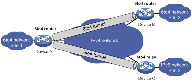
· ISATAP tunneling—A point-to-multipoint automatic tunnel. It provides a solution to connect an IPv6 host and an IPv6 network over an IPv4 network. ISATAP tunnels are mainly used for communication between IPv6 routers or between an IPv6 host and an IPv6 router over an IPv4 network.
Figure 121 Principle of ISATAP tunneling
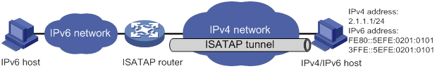
· 6RD tunneling
? Ordinary 6RD tunneling—A point-to-multipoint automatic tunnel. It is an extension of 6to4 tunneling. The IPv6 prefix of a 6RD network is assigned by the service provider and is not limited to the prefix 2002::/16. 6RD does not require to embed all 32 bits of an IPv4 address in a 6RD address.
Figure 122 shows the format of 6RD address—an IPv6 address with a 6RD prefix and an embedded IPv4 address.
- 6RD prefix—IPv6 prefix assigned by the service provider to a 6RD network.
- IPv4 address—All or part of the IPv4 tunnel source address in hexadecimal notation. For example, assume that the IPv4 tunnel source address is 1.2.3.4 and both the IPv4 prefix length and suffix length are specified as 8 bits. Then, the prefix of the IPv4 address 1.2.3.4 is 01, the suffix is 04, and the embedded IPv4 address is 0203.
- 6RD delegated prefix—The 6RD prefix and the embedded IPv4 address together form a 6RD delegated prefix. It uniquely identifies a 6RD network (an IPv6 network where all hosts use 6RD addresses).
- Subnet ID—Identifies a subnet in the 6RD network.
- Interface ID—The subnet ID and the interface ID together identify a host in the 6RD network.
Figure 122 6RD address format
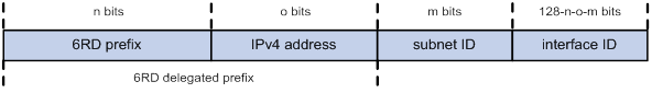
? 6RD relay—Connects a 6RD network and an IPv6 network that uses a prefix other than a 6RD delegated prefix. A 6RD border relay (BR) router is a gateway that forwards packets from a 6RD network to an IPv6 network. The border router connected to the 6RD network is called 6RD CE.
As shown in Figure 123, for the 6RD network site 1 to communicate with the IPv6 network site 3 over a 6RD tunnel, you must configure 6RD relay. Configure a static route on the border router (Device A) in the 6RD network. The next hop address must be the 6RD address of the 6RD BR router (Device C). Device A forwards all packets destined for the IPv6 network over the 6RD tunnel, and Device C then forwards them to the IPv6 network.
Figure 123 Principle of 6RD tunneling and 6RD relay
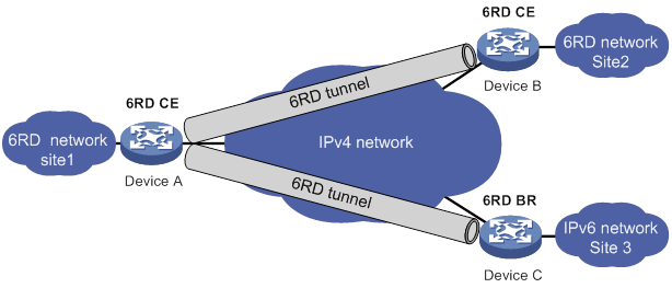
IPv4 over IPv4 tunneling
IPv4 over IPv4 tunneling (RFC 1853) enables isolated IPv4 networks to communicate. For example, an IPv4 over IPv4 tunnel can connect isolated private IPv4 networks over a public IPv4 network.
Figure 124 IPv4 over IPv4 tunnel

Figure 124 shows the encapsulation and de-encapsulation processes.
· Encapsulation:
a. Device A receives an IP packet from an IPv4 host and submits it to the IP protocol stack.
b. The IPv4 protocol stack determines how to forward the packet according to the destination address in the IP header. If the packet is destined for the IPv4 host connected to Device B, Device A delivers the packet to the tunnel interface.
c. The tunnel interface adds a new IPv4 header to the IPv4 packet and submits it to the IP protocol stack.
In the new header, the source IP address specifies the tunnel source, and the destination IP address specifies the tunnel destination.
d. The IP protocol stack uses the destination IP address of the new IP header to look up the routing table, and then sends the packet out.
· De-encapsulation:
e. After receiving the packet, Device B delivers it to the IP protocol stack.
f. If the protocol number is 4 (indicating an IPv4 packet is encapsulated within the packet), the IP protocol stack delivers the packet to the tunnel module for de-encapsulation.
g. The tunnel module de-encapsulates the IP packet and sends it back to the IP protocol stack.
h. The protocol stack forwards the de-encapsulated packet.
IPv4 over IPv6 tunneling
Implementation
IPv4 over IPv6 tunneling adds an IPv6 header to IPv4 packets so that the IPv4 packets can pass an IPv6 network through a tunnel to realize interworking between isolated IPv4 networks.
Figure 125 IPv4 over IPv6 tunnel
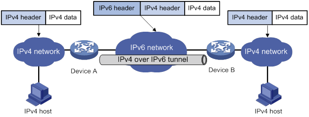
Figure 125 shows the encapsulation and de-encapsulation processes.
· Encapsulation:
a. Upon receiving an IPv4 packet, Device A delivers it to the IPv4 protocol stack.
b. The IPv4 protocol stack uses the destination address of the packet to determine the egress interface. If the egress interface is the tunnel interface, the IPv4 protocol stack delivers the packet to the tunnel interface.
c. The tunnel interface adds an IPv6 header to the original IPv4 packet and delivers the packet to the IPv6 protocol stack.
d. The IPv6 protocol stack uses the destination IPv6 address of the packet to look up the routing table, and then sends it out.
· De-encapsulation:
e. Upon receiving the IPv6 packet from the attached IPv6 network, Device B delivers the packet to the IPv6 protocol stack to examine the protocol type encapsulated in the data portion of the packet.
f. If the protocol type is IPv4, the IPv6 protocol stack delivers the packet to the tunneling module.
g. The tunneling module removes the IPv6 header and delivers the remaining IPv4 packet to the IPv4 protocol stack.
h. The IPv4 protocol stack forwards the IPv4 packet.
Tunnel modes
· IPv4 over IPv6 manual tunnel
A point-to-point link and its source and destination IPv6 addresses are manually configured. You can establish an IPv4 over IPv6 manual tunnel to connect isolated IPv4 networks over an IPv6 network.
· DS-Lite tunnel
Dual Stack Lite (DS-Lite) is a combination of the tunneling and NAT technologies. NAT translates the private IPv4 addresses of the IPv4 hosts before the hosts reach the IPv4 public network.
DS-Lite tunnel supports only an IPv4 host in a private network initiating communication with an IPv4 host on the Internet. It does not support an IPv4 host on the Internet initiating communication with an IPv4 host in a private network.
Figure 126 DS-Lite tunnel
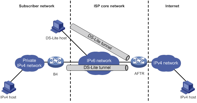
As shown in Figure 126, the DS-Lite feature contains the following components:
? Basic Bridging BroadBand (B4) element
The B4 element is typically a CPE router that connects end hosts. IPv4 packets entering the B4 router are encapsulated into IPv6 packets and sent to the AFTR. IPv6 packets from the AFTR are de-encapsulated into IPv4 packets and sent to the subscriber's network.
Hosts that can act as the B4 router are referred to as DS-Lite hosts.
? Address Family Transition Router (AFTR)
An AFTR resides in the ISP network and terminates the tunnel from the B4 router. NAT is also implemented on the interface that is connected to the public IPv4 network.
An AFTR de-encapsulates the tunneled packet, translates the network address, and routes the packet to the destination IPv4 network. For IPv4 packets coming from the public IPv4 network, the AFTR performs reverse address translation and sends them to the B4 router by using the DS-Lite tunnel.
Figure 127 Packet forwarding process in DS-Lite
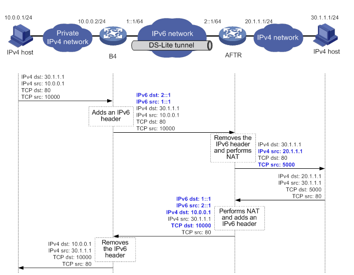
As shown in Figure 127, the packet forwarding process in DS-Lite is as follows:
a. Upon receiving a packet from the private IPv4 network, the B4 router adds an IPv6 header to the packet and sends the IPv6 packet to the AFTR through the tunnel.
b. The AFTR performs the following operations:
- Removes the IPv6 header from the tunneled packet.
- Assigns a tunnel ID for the B4 router.
- Records the mapping between the IPv6 address of the B4 router (the source IPv6 address of the packet), and the tunnel ID.
c. After de-encapsulation, the AFTR translates the source private IPv4 address of the packet into a public IPv4 address and sends the packet to the destination IPv4 host. The AFTR also maps the NAT entries to the tunnel ID so that IPv4 networks connected to different B4 routers can use the same address space.
d. Upon receiving the response packet from the public network, the AFTR translates the destination public IPv4 address into the private IPv4 address. The AFTR performs the following operations:
- Looks up the IPv6 address-tunnel ID mapping to obtain the IP address of the B4 router.
- Uses the address as the destination address of the encapsulated IPv6 packet.
- Forwards the packet to the B4 router.
Figure 127 shows an example of PAT translation for dynamic NAT. Typically, dynamic NAT is used. When you use static NAT for DS-Lite tunneling, make sure the IP addresses of private IPv4 networks connected to different B4 routers do not overlap. For more information about NAT, see "Configuring NAT."
IPv6 over IPv6 tunneling
IPv6 over IPv6 tunneling (RFC 2473) enables isolated IPv6 networks to communicate with each other over another IPv6 network. For example, two isolated IPv6 networks that do not want to show their addresses to the Internet can use an IPv6 over IPv6 tunnel to communicate with each other.
Figure 128 Principle of IPv6 over IPv6 tunneling

Figure 128 shows the encapsulation and de-encapsulation processes.
· Encapsulation:
a. After receiving an IPv6 packet, Device A submits it to the IPv6 protocol stack.
b. The IPv6 protocol stack uses the destination IPv6 address of the packet to find the egress interface. If the egress interface is the tunnel interface, the stack delivers it to the tunnel interface.
c. After receiving the packet, the tunnel interface adds an IPv6 header to it and submits it to the IPv6 protocol stack.
d. The IPv6 protocol stack forwards the packet according to its destination IPv6 address.
· De-encapsulation:
e. Upon receiving the IPv6 packet, Device B delivers it to the IPv6 protocol stack.
f. The IPv6 protocol stack checks the protocol type of the data portion encapsulated in the IPv6 packet. If the encapsulation protocol is IPv6, the stack delivers the packet to the tunnel module.
g. The tunnel module de-encapsulates the packet and sends it back to the IPv6 protocol stack.
h. The IPv6 protocol stack forwards the IPv6 packet.
Protocols and standards
· RFC 1853, IP in IP Tunneling
· RFC 2473, Generic Packet Tunneling in IPv6 Specification
· RFC 2893, Transition Mechanisms for IPv6 Hosts and Routers
· RFC 3056, Connection of IPv6 Domains via IPv4 Clouds
· RFC 4214, Intra-Site Automatic Tunnel Addressing Protocol (ISATAP)
· RFC 6333, Dual-Stack Lite Broadband Deployments Following IPv4 Exhaustion
Command and hardware compatibility
Commands and descriptions for centralized devices apply to the following routers:
· MSR810/810-W/810-W-DB/810-LM/810-W-LM/810-10-PoE/810-LM-HK/810-W-LM-HK/810-LMS/810-LUS.
· MSR2600-6-X1/2600-10-X1.
· MSR 2630.
· MSR3600-28/3600-51.
· MSR3600-28-SI/3600-51-SI.
· MSR3610-X1/3610-X1-DP/3610-X1-DC/3610-X1-DP-DC.
· MSR 3610/3620/3620-DP/3640/3660.
· MSR810-LM-GL/810-W-LM-GL/830-6EI-GL/830-10EI-GL/830-6HI-GL/830-10HI-GL/2600-6-X1-GL/3600-28-SI-GL.
Commands and descriptions for distributed devices apply to the following routers:
· MSR5620.
· MSR 5660.
· MSR 5680.
Tunneling configuration task list
|
Tasks at a glance |
|
(Required.) Configuring a tunnel interface |
|
Perform one of the following tasks: · Configuring an IPv6 over IPv4 tunnel: ? Configuring an IPv6 over IPv4 manual tunnel ? Configuring an automatic IPv4-compatible IPv6 tunnel ? Configuring an ISATAP tunnel · Configuring an IPv4 over IPv4 tunnel · Configuring an IPv4 over IPv6 tunnel: ? Configuring an IPv4 over IPv6 manual tunnel |
Configuring a tunnel interface
Configure a tunnel interface (Layer 3 virtual interface) at both ends of a tunnel. The devices use the tunnel interface to identify, process, and send packets for the tunnel.
When an active/standby switchover occurs or the standby card is removed on a distributed device, the tunnel interfaces configured on the active or standby card still exist. To delete a tunnel interface, use the undo interface tunnel command.
To configure a tunnel interface:
|
Step |
Command |
Remarks |
||
|
1. Enter system view. |
system-view |
N/A |
||
|
2. Create a tunnel interface, specify the tunnel mode, and enter tunnel interface view. |
interface tunnel number mode { advpn { gre | udp } [ ipv6 ] | ds-lite-aftr | evi | gre [ ipv6 ] | ipsec [ ipv6 ] | ipv4-ipv4 | ipv6 | ipv6-ipv4 [ 6rd | 6to4 | auto-tunnel | isatap ] | mpls-te | nve | vxlan } |
Support for the keywords depends on the device model. For more information about the keywords and hardware compatibility, see Layer 3—IP Services Command Reference. By default, no tunnel interfaces exist. When you create a new tunnel interface, you must specify the tunnel mode. When you enter the view of an existing tunnel interface, you do not need to specify the tunnel mode. For packet tunneling to succeed, the two ends of a tunnel must use the same tunnel mode. |
||
|
3. (Optional.) Configure a description for the interface. |
description text |
By default, the description for a tunnel interface is Tunnel number Interface. |
||
|
4. (Optional.) Specify a primary traffic processing slot for the interface. |
·
Distributed devices in standalone
mode/centralized devices in IRF mode: ·
Distributed devices in IRF mode: |
Support for the commands depends on the device model. For more information about the commands and hardware compatibility, see Layer 3—IP Services Command Reference. By default, no primary traffic processing slot is specified for an interface. |
||
|
5. (Optional.) Specify a backup traffic processing slot for the interface. |
·
Distributed devices in standalone
mode/centralized devices in IRF mode: ·
Distributed devices in IRF mode: |
Support for the commands depends on the device model. For more information about the commands and hardware compatibility, see Layer 3—IP Services Command Reference. By default, no backup traffic processing slot is specified for an interface. |
||
|
6. Set the MTU of the tunnel interface. |
mtu size |
If the tunnel interface has never been up, the default MTU is 64000 bytes. If the tunnel interface is up, its default MTU is identical to the outgoing interface's MTU minus the length of the tunnel headers. The outgoing interface is automatically obtained through routing table lookup based on the tunnel destination address. |
||
|
7. Set the expected bandwidth for the tunnel interface. |
bandwidth bandwidth-value |
The default expected bandwidth (in kbps) is the interface maximum rate divided by 1000. The expected bandwidth for the tunnel interface affects the link cost value. For more information, see Layer 3—IP Routing Configuration Guide. |
||
|
8. Set the ToS for tunneled packets. |
tunnel tos { tos-value | copy-inner-tos } |
Support for the copy-inner-tos keyword depends on the device model. For more information about the keyword and hardware compatibility, see Layer 3—IP Services Command Reference. For VXLAN tunneled packets, the default ToS is 0. For non-VXLAN tunneled packets, the default ToS is the same as the ToS of the original packets. The copy-inner-tos keyword is supported only by VXLAN tunnels. |
||
|
9. Set the TTL for tunneled packets. |
tunnel ttl ttl-value |
The default TTL for tunneled packets is 255. |
||
|
10. Specify the VPN instance to which the tunnel destination belongs. |
tunnel vpn-instance vpn-instance-name |
By default, the tunnel destination belongs to the public network. For a tunnel interface to come up, the tunnel source and destination must belong to the same VPN. To specify a VPN instance for the tunnel source, use the ip binding vpn-instance command on the tunnel source interface. |
||
|
11. (Optional.) Restore the default settings of the tunnel interface. |
default |
N/A |
||
|
12. (Optional.) Shut down the tunnel interface. |
shutdown |
By default, the state of a tunnel interface is not Administratively DOWN. |
||
Configuring an IPv6 over IPv4 manual tunnel
Configuration restrictions and guidelines
Follow these guidelines when you configure an IPv6 over IPv4 manual tunnel:
· The tunnel destination address specified on the local device must be identical with the tunnel source address specified on the tunnel peer device.
· Do not specify the same tunnel source and destination addresses for the tunnel interfaces in the same mode on a device.
· To ensure correct packet forwarding, identify whether the destination IPv6 network and the IPv6 address of the local tunnel interface are on the same subnet. If they are not, configure a route reaching the destination IPv6 network through the tunnel interface. You can configure the route by using one of the following methods:
? Configure a static route, and specify the local tunnel interface as the egress interface or specify the IPv6 address of the peer tunnel interface as the next hop.
? Enable a dynamic routing protocol on both tunnel interfaces to achieve the same purpose.
For more information about route configuration, see Layer 3—IP Routing Configuration Guide.
Configuration procedure
To configure an IPv6 over IPv4 manual tunnel:
|
Step |
Command |
Remarks |
|
1. Enter system view. |
system-view |
N/A |
|
2. Enter IPv6 over IPv4 manual tunnel interface view. |
interface tunnel number [ mode ipv6-ipv4 ] |
N/A |
|
3. Specify an IPv6 address for the tunnel interface. |
By default, no IPv6 address is configured for the tunnel interface. |
|
|
4. Configure a source address or source interface for the tunnel interface. |
source { ipv4-address | interface-type interface-number } |
By default, no source address or source interface is configured for the tunnel interface. If you specify a source address, it is used as the source IP address of tunneled packets. If you specify a source interface, the primary IP address of this interface is used as the source IP address of tunneled packets. |
|
5. Configure a destination address for the tunnel interface. |
destination ipv4-address |
By default, no destination address is configured for the tunnel interface. The tunnel destination address must be the IP address of the receiving interface on the tunnel peer. It is used as the destination IP address of tunneled packets. |
|
6. (Optional.) Set the DF bit for tunneled packets. |
tunnel dfbit enable |
By default, the DF bit is not set for tunneled packets. |
|
7. Return to system view. |
quit |
N/A |
|
8. (Optional.) Enable dropping IPv6 packets that use IPv4-compatible IPv6 addresses. |
tunnel discard ipv4-compatible-packet |
Support for this command depends on the device model. For more information about the command and hardware compatibility, see Layer 3—IP Services Command Reference. By default, IPv6 packets that use IPv4-compatible IPv6 packets are not dropped. |
Configuration example
Network requirements
As shown in Figure 129, configure an IPv6 over IPv4 tunnel between Router A and Router B so the two IPv6 networks can reach each other over the IPv4 network. Because the tunnel destination IPv4 address cannot be automatically obtained from the destination IPv6 addresses, configure an IPv6 over IPv4 manual tunnel.

Configuration procedure
Make sure Router A and Router B can reach each other through IPv4.
· Configure Router A:
# Specify an IPv4 address for GigabitEthernet 2/0/2.
<RouterA> system-view
[RouterA] interface gigabitethernet 2/0/2
[RouterA-GigabitEthernet2/0/2] ip address 192.168.100.1 255.255.255.0
[RouterA-GigabitEthernet2/0/2] quit
# Specify an IPv6 address for GigabitEthernet 2/0/1.
[RouterA] interface gigabitethernet 2/0/1
[RouterA-GigabitEthernet2/0/1] ipv6 address 3002::1 64
[RouterA-GigabitEthernet2/0/1] quit
# Create the IPv6 over IPv4 manual tunnel interface Tunnel 0.
[RouterA] interface tunnel 0 mode ipv6-ipv4
# Specify an IPv6 address for the tunnel interface.
[RouterA-Tunnel0] ipv6 address 3001::1/64
# Specify GigabitEthernet 2/0/2 as the source interface of the tunnel interface.
[RouterA-Tunnel0] source gigabitethernet 2/0/2
# Specify the destination address for the tunnel interface as the IP address of GigabitEthernet 2/0/2 on Router B.
[RouterA-Tunnel0] destination 192.168.50.1
[RouterA-Tunnel0] quit
# Configure a static route destined for IPv6 network 2 through Tunnel 0.
[RouterA] ipv6 route-static 3003:: 64 tunnel 0
· Configure Router B:
# Specify an IPv4 address for GigabitEthernet 2/0/2.
<RouterB> system-view
[RouterB] interface gigabitethernet 2/0/2
[RouterB-GigabitEthernet2/0/2] ip address 192.168.50.1 255.255.255.0
[RouterB-GigabitEthernet2/0/2] quit
# Specify an IPv6 address for GigabitEthernet 2/0/1.
[RouterB] interface gigabitethernet 2/0/1
[RouterB-GigabitEthernet2/0/1] ipv6 address 3003::1 64
[RouterB-GigabitEthernet2/0/1] quit
# Create the IPv6 over IPv4 manual tunnel interface Tunnel 0.
[RouterB] interface tunnel 0 mode ipv6-ipv4
# Specify an IPv6 address for the tunnel interface.
[RouterB-Tunnel0] ipv6 address 3001::2/64
# Specify GigabitEthernet 2/0/2 as the source interface of the tunnel interface.
[RouterB-Tunnel0] source gigabitethernet 2/0/2
# Specify the destination address for the tunnel interface as the IP address of GigabitEthernet 2/0/2 on Router A.
[RouterB-Tunnel0] destination 192.168.50.1
[RouterB-Tunnel0] quit
# Configure a static route destined for IPv6 network 1 through Tunnel 0.
[RouterB] ipv6 route-static 3002:: 64 tunnel 0
Verifying the configuration
# Verify that Router B and Router A can ping the IPv6 address of GigabitEthernet 2/0/1 of each other. This example uses Router A.
[RouterA] ping ipv6 3003::1
Ping6(56 data bytes) 3001::1 --> 3003::1, press CTRL C to break
56 bytes from 3003::1, icmp_seq=0 hlim=64 time=45.000 ms
56 bytes from 3003::1, icmp_seq=1 hlim=64 time=10.000 ms
56 bytes from 3003::1, icmp_seq=2 hlim=64 time=4.000 ms
56 bytes from 3003::1, icmp_seq=3 hlim=64 time=10.000 ms
56 bytes from 3003::1, icmp_seq=4 hlim=64 time=11.000 ms
--- Ping6 statistics for 3003::1 ---
5 packet(s) transmitted, 5 packet(s) received, 0.0% packet loss
round-trip min/avg/max/std-dev = 4.000/16.000/45.000/14.711 ms
Configuring an automatic IPv4-compatible IPv6 tunnel
Configuration restrictions and guidelines
Follow these guidelines when you configure an automatic IPv4-compatible IPv6 tunnel:
· You do not need to configure a destination address for an automatic IPv4-compatible IPv6 tunnel. The destination address of the tunnel is embedded in the destination IPv4-compatible IPv6 address.
· Do not specify the same source addresses for local tunnel interfaces in the same tunnel mode.
Configuration procedure
To configure an automatic IPv4-compatible IPv6 tunnel:
|
Step |
Command |
Remarks |
|
1. Enter system view. |
system-view |
N/A |
|
2. Enter automatic IPv4-compatible IPv6 tunnel interface view. |
interface tunnel number [ mode ipv6-ipv4 auto-tunnel ] |
N/A |
|
3. Specify an IPv6 address for the tunnel interface. |
By default, no IPv6 address is configured for the tunnel interface. |
|
|
4. Configure a source address or source interface for the tunnel interface. |
source { ipv4-address | interface-type interface-number } |
By default, no source address or source interface is configured for the tunnel interface. If you specify a source address, it is used as the source IP address of tunneled packets. If you specify a source interface, the primary IP address of this interface is used as the source IP address of tunneled packets. |
|
5. (Optional.) Set the DF bit for tunneled packets. |
tunnel dfbit enable |
By default, the DF bit is not set for tunneled packets. |
|
6. Return to system view. |
quit |
N/A |
Configuration example
Network requirements
As shown in Figure 130, dual-stack routers Router A and Router B communicate over an IPv4 network. Configure an automatic IPv4-compatible IPv6 tunnel between the two routers to enable IPv6 communications over the IPv4 network.
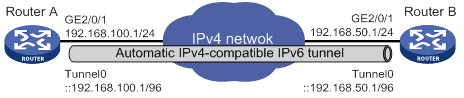
Configuration procedure
Make sure Router A and Router B can reach each other through IPv4.
· Configure Router A:
# Specify an IPv4 address for GigabitEthernet 2/0/1.
<RouterA> system-view
[RouterA] interface gigabitethernet 2/0/1
[RouterA-GigabitEthernet2/0/1] ip address 192.168.100.1 255.255.255.0
[RouterA-GigabitEthernet2/0/1] quit
# Create an automatic IPv4-compatible IPv6 tunnel.
[RouterA] interface tunnel 0 mode ipv6-ipv4 auto-tunnel
# Specify an IPv4-compatible IPv6 address for the tunnel interface.
[RouterA-Tunnel0] ipv6 address ::192.168.100.1/96
# Specify GigabitEthernet 2/0/1 as the source interface of the tunnel interface.
[RouterA-Tunnel0] source gigabitethernet 2/0/1
· Configure Router B:
# Specify an IPv4 address for GigabitEthernet 2/0/1.
<RouterB> system-view
[RouterB] interface gigabitethernet 2/0/1
[RouterB-GigabitEthernet2/0/1] ip address 192.168.50.1 255.255.255.0
[RouterB-GigabitEthernet2/0/1] quit
# Create an automatic IPv4-compatible IPv6 tunnel.
[RouterB] interface tunnel 0 mode ipv6-ipv4 auto-tunnel
# Specify an IPv4-compatible IPv6 address for the tunnel interface.
[RouterB-Tunnel0] ipv6 address ::192.168.50.1/96
# Specify GigabitEthernet 2/0/1 as the source interface of the tunnel interface.
[RouterB-Tunnel0] source gigabitethernet 2/0/1
Verifying the configuration
# Use the display ipv6 interface command to display tunnel interface status on Router A and Router B. Verify that the interface tunnel 0 is up. (Details not shown.)
# Verify that Router B and Router A can ping the IPv4-compatible IPv6 address of each other. This example uses Router A.
[RouterA-Tunnel0] ping ipv6 ::192.168.50.1
Ping6(56 data bytes) ::192.168.100.1 --> ::192.168.50.1, press CTRL_C to break
56 bytes from ::192.168.50.1, icmp_seq=0 hlim=64 time=17.000 ms
56 bytes from ::192.168.50.1, icmp_seq=1 hlim=64 time=9.000 ms
56 bytes from ::192.168.50.1, icmp_seq=2 hlim=64 time=11.000 ms
56 bytes from ::192.168.50.1, icmp_seq=3 hlim=64 time=9.000 ms
56 bytes from ::192.168.50.1, icmp_seq=4 hlim=64 time=11.000 ms
--- Ping6 statistics for ::192.168.50.1 ---
5 packet(s) transmitted, 5 packet(s) received, 0.0% packet loss
round-trip min/avg/max/std-dev = 9.000/11.400/17.000/2.939 ms
Configuring a 6to4 tunnel
Configuration restrictions and guidelines
Follow these guidelines when you configure a 6to4 tunnel:
· You do not need to configure a destination address for a 6to4 tunnel, because the destination IPv4 address is embedded in the 6to4 IPv6 address.
· Do not specify the same source addresses for local tunnel interfaces in the same tunnel mode.
· Automatic tunnels do not support dynamic routing. You must configure a static route destined for the destination IPv6 network if the destination IPv6 network is not in the same subnet as the IPv6 address of the tunnel interface. You can specify the local tunnel interface as the egress interface of the route or specify the IPv6 address of the peer tunnel interface as the next hop of the route. For more information about route configuration, see Layer 3—IP Routing Configuration Guide.
Configuration procedure
To configure a 6to4 tunnel:
|
Step |
Command |
Remarks |
|
1. Enter system view. |
system-view |
N/A |
|
2. Enter 6to4 tunnel interface view. |
interface tunnel number [ mode ipv6-ipv4 6to4 ] |
N/A |
|
3. Specify an IPv6 address for the tunnel interface. |
By default, no IPv6 address is configured for the tunnel interface. |
|
|
4. Configure a source address or source interface for the tunnel interface. |
source { ipv4-address | interface-type interface-number } |
By default, no source address or source interface is configured for the tunnel interface. If you specify a source address, it is used as the source IP address of tunneled packets. If you specify a source interface, the primary IP address of this interface is used as the source IP address of tunneled packets. |
|
5. (Optional.) Set the DF bit for tunneled packets. |
tunnel dfbit enable |
By default, the DF bit is not set for tunneled packets. |
|
6. Return to system view. |
quit |
N/A |
|
7. (Optional.) Enable dropping IPv6 packets that use IPv4-compatible IPv6 addresses. |
tunnel discard ipv4-compatible-packet |
Support for this command depends on the device model. For more information about the command and hardware compatibility, see Layer 3—IP Services Command Reference. By default, IPv6 packets that use IPv4-compatible IPv6 packets are not dropped. |
6to4 tunnel configuration example
Network requirements
As shown in Figure 131, configure a 6to4 tunnel between 6to4 routers Router A and Router B so the two hosts can reach each other over the IPv4 network.
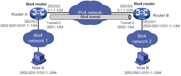
Requirements analysis
To enable communication between 6to4 networks, configure 6to4 addresses for 6to4 routers and hosts in the 6to4 networks.
· The IPv4 address of GigabitEthernet 2/0/2 on Router A is 2.1.1.1/24, and the corresponding 6to4 prefix is 2002:0201:0101::/48. Host A must use this prefix.
· The IPv4 address of GigabitEthernet 2/0/2 on Router B is 5.1.1.1/24, and the corresponding 6to4 prefix is 2002:0501:0101::/48. Host B must use this prefix.
Configuration procedure
Make sure Router A and Router B can reach each other through IPv4.
· Configure Router A:
# Specify an IPv4 address for GigabitEthernet 2/0/2.
<RouterA> system-view
[RouterA] interface gigabitethernet 2/0/2
[RouterA-GigabitEthernet2/0/2] ip address 2.1.1.1 24
[RouterA-GigabitEthernet2/0/2] quit
# Specify a 6to4 address for GigabitEthernet 2/0/1.
[RouterA] interface gigabitethernet 2/0/1
[RouterA-GigabitEthernet2/0/1] ipv6 address 2002:0201:0101:1::1/64
[RouterA-GigabitEthernet2/0/1] quit
# Create the 6to4 tunnel interface Tunnel 0.
[RouterB] interface tunnel 0 mode ipv6-ipv4 6to4
# Specify an IPv6 address for the tunnel interface.
[RouterA-Tunnel0] ipv6 address 3001::1/64
# Specify the source interface as GigabitEthernet 2/0/2 for the tunnel interface.
[RouterA-Tunnel0] source gigabitethernet 2/0/2
[RouterA-Tunnel0] quit
# Configure a static route destined for 2002::/16 through the tunnel interface.
[RouterA] ipv6 route-static 2002:: 16 tunnel 0
· Configure Router B:
# Specify an IPv4 address for GigabitEthernet 2/0/2.
<RouterB> system-view
[RouterB] interface gigabitethernet 2/0/2
[RouterB-GigabitEthernet2/0/2] ip address 5.1.1.1 24
[RouterB-GigabitEthernet2/0/2] quit
# Specify a 6to4 address for GigabitEthernet 2/0/1.
[RouterB] interface gigabitethernet 2/0/1
[RouterB-GigabitEthernet2/0/1] ipv6 address 2002:0501:0101:1::1/64
[RouterB-GigabitEthernet2/0/1] quit
# Create the 6to4 tunnel interface Tunnel 0.
[RouterB] interface tunnel 0 mode ipv6-ipv4 6to4
# Specify an IPv6 address for the tunnel interface.
[RouterB-Tunnel0] ipv6 address 3002::1/64
# Specify the source interface as GigabitEthernet 2/0/2 for the tunnel interface.
[RouterB-Tunnel0] source gigabitethernet 2/0/2
[RouterB-Tunnel0] quit
# Configure a static route destined for 2002::/16 through the tunnel interface.
[RouterB] ipv6 route-static 2002:: 16 tunnel 0
Verifying the configuration
# Verify that Linux-running hosts Host A and Host B can ping each other.
D:\>ping6 -s 2002:201:101:1::2 2002:501:101:1::2
Pinging 2002:501:101:1::2
from 2002:201:101:1::2 with 32 bytes of data:
Reply from 2002:501:101:1::2: bytes=32 time=13ms
Reply from 2002:501:101:1::2: bytes=32 time=1ms
Reply from 2002:501:101:1::2: bytes=32 time=1ms
Reply from 2002:501:101:1::2: bytes=32 time<1ms
Ping statistics for 2002:501:101:1::2:
Packets: Sent = 4, Received = 4, Lost = 0 (0% loss),
Approximate round trip times in milli-seconds:
Minimum = 0ms, Maximum = 13ms, Average = 3ms
6to4 relay configuration example
Network requirements
As shown in Figure 132, Router A is a 6to4 router, and 6to4 addresses are used on the connected IPv6 network. Router B acts as a 6to4 relay router and is connected to an IPv6 network (2001::/16). Configure a 6to4 tunnel between Router A and Router B to make Host A and Host B reachable to each other.
The configuration on a 6to4 relay router is similar to that on a 6to4 router. However, to enable communication between the 6to4 network and the IPv6 network, you must configure a route to the IPv6 network on the 6to4 router. The IPv4 address of GigabitEthernet 2/0/2 on the relay router is 6.1.1.1/24 and its corresponding 6to4 prefix is 2002:0601:0101::/48. The next hop of the static route must be an address using this prefix.
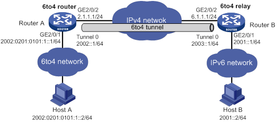
Configuration procedure
Make sure Router A and Router B can reach each other through IPv4.
· Configure Router A:
# Specify an IPv4 address for GigabitEthernet 2/0/2.
<RouterA> system-view
[RouterA] interface gigabitethernet 2/0/2
[RouterA-GigabitEthernet2/0/2] ip address 2.1.1.1 255.255.255.0
[RouterA-GigabitEthernet2/0/2] quit
# Specify a 6to4 address for GigabitEthernet 2/0/1.
[RouterA] interface gigabitethernet 2/0/1
[RouterA-GigabitEthernet2/0/1] ipv6 address 2002:0201:0101:1::1/64
[RouterA-GigabitEthernet2/0/1] quit
# Create the 6to4 tunnel interface Tunnel 0.
[RouterA] interface tunnel 0 mode ipv6-ipv4 6to4
# Specify an IPv6 address for the tunnel interface.
[RouterA-Tunnel0] ipv6 address 2002::1/64
# Specify GigabitEthernet 2/0/2 as the source interface of the tunnel interface.
[RouterA-Tunnel0] source gigabitethernet 2/0/2
[RouterA-Tunnel0] quit
# Configure a static route to the 6to4 relay router.
[RouterA] ipv6 route-static 2002:0601:0101:: 64 tunnel 0
# Configure a default route to reach the IPv6 network, which specifies the next hop as the 6to4 address of the relay router.
[RouterA] ipv6 route-static :: 0 2002:0601:0101::1
· Configure Router B:
# Specify an IPv4 address for GigabitEthernet 2/0/2.
<RouterB> system-view
[RouterB] interface gigabitethernet 2/0/2
[RouterB-GigabitEthernet2/0/2] ip address 6.1.1.1 255.255.255.0
[RouterB-GigabitEthernet2/0/2] quit
# Specify an IPv6 address for GigabitEthernet 2/0/1.
[RouterB] interface gigabitethernet 2/0/1
[RouterB-GigabitEthernet2/0/1] ipv6 address 2001::1/16
[RouterB-GigabitEthernet2/0/1] quit
# Create the 6to4 tunnel interface Tunnel 0.
[RouterB] interface tunnel 0 mode ipv6-ipv4 6to4
# Specify an IPv6 address for the tunnel interface.
[RouterB-Tunnel0] ipv6 address 2003::1/64
# Specify GigabitEthernet 2/0/2 as the source interface of the tunnel interface.
[RouterB-Tunnel0] source gigabitethernet 2/0/2
[RouterB-Tunnel0] quit
# Configure a static route destined for 2002::/16 through the tunnel interface.
[RouterB] ipv6 route-static 2002:: 16 tunnel 0
Verifying the configuration
# Verify that Linux-running hosts Host A and Host B can ping each other.
D:\>ping6 -s 2002:201:101:1::2 2001::2
Pinging 2001::2
from 2002:201:101:1::2 with 32 bytes of data:
Reply from 2001::2: bytes=32 time=13ms
Reply from 2001::2: bytes=32 time=1ms
Reply from 2001::2: bytes=32 time=1ms
Reply from 2001::2: bytes=32 time<1ms
Ping statistics for 2001::2:
Packets: Sent = 4, Received = 4, Lost = 0 (0% loss),
Approximate round trip times in milli-seconds:
Minimum = 0ms, Maximum = 13ms, Average = 3ms
Configuring an ISATAP tunnel
Configuration restrictions and guidelines
Follow these guidelines when you configure an ISATAP tunnel:
· You do not need to configure a destination address for an ISATAP tunnel, because the destination IPv4 address is embedded in the ISATAP address.
· Do not specify the same source addresses for local tunnel interfaces in the same tunnel mode.
· Because automatic tunnels do not support dynamic routing, configure a static route destined for the destination IPv6 network at each tunnel end. You can specify the local tunnel interface as the egress interface of the route or specify the IPv6 address of the peer tunnel interface as the next hop of the route. For more information about route configuration, see Layer 3—IP Routing Configuration Guide.
Configuration procedure
To configure an ISATAP tunnel:
|
Step |
Command |
Remarks |
|
1. Enter system view. |
system-view |
N/A |
|
2. Enter ISATAP tunnel interface view. |
interface tunnel number [ mode ipv6-ipv4 isatap ] |
N/A |
|
3. Specify an IPv6 address for the tunnel interface. |
By default, no IPv6 address is configured for the tunnel interface. |
|
|
4. Configure a source address or source interface for the tunnel interface. |
source { ipv4-address | interface-type interface-number } |
By default, no source address or source interface is configured for the tunnel interface. If you specify a source address, it is used as the source IP address of tunneled packets. If you specify a source interface, the primary IP address of this interface is used as the source IP address of tunneled packets. |
|
5. (Optional.) Set the DF bit for tunneled packets. |
tunnel dfbit enable |
By default, the DF bit is not set for tunneled packets. |
|
6. Return to system view. |
quit |
N/A |
|
7. (Optional.) Enable dropping IPv6 packets that use IPv4-compatible IPv6 addresses. |
tunnel discard ipv4-compatible-packet |
Support for this command depends on the device model. For more information about the command and hardware compatibility, see Layer 3—IP Services Command Reference. By default, IPv6 packets that use IPv4-compatible IPv6 packets are not dropped. |
Configuration example
Network requirements
As shown in Figure 133, configure an ISATAP tunnel between the router and the ISATAP host so the ISATAP host in the IPv4 network can access the IPv6 network.
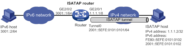
Configuration procedure
· Configure the router:
# Specify an IPv6 address for GigabitEthernet 2/0/2.
<Router> system-view
[Router] interface gigabitethernet 2/0/2
[Router-GigabitEthernet2/0/2] ipv6 address 3001::1/64
[Router-GigabitEthernet2/0/2] quit
# Specify an IPv4 address for GigabitEthernet 2/0/1.
[Router] interface gigabitethernet 2/0/1
[Router-GigabitEthernet2/0/1] ip address 1.1.1.1 255.0.0.0
[Router-GigabitEthernet2/0/1] quit
# Create the ISATAP tunnel interface Tunnel 0.
[Router] interface tunnel 0 mode ipv6-ipv4 isatap
# Specify an EUI-64 IPv6 address for the tunnel interface.
[Router-Tunnel0] ipv6 address 2001:: 64 eui-64
# Specify GigabitEthernet 2/0/1 as the source interface of the tunnel interface.
[Router-Tunnel0] source gigabitethernet 2/0/1
# Disable RA suppression so that the ISATAP host can acquire information such as the address prefix from the RA message advertised by the ISATAP router.
[Router-Tunnel0] undo ipv6 nd ra halt
[Router-Tunnel0] quit
· Configure the ISATAP host:
Configurations on the ISATAP host vary by operating system. The following configuration is performed on Windows XP.
# Install IPv6.
C:\>ipv6 install
# On a host running Windows XP, the ISATAP interface is typically interface 2. Display information about the ISATAP interface.
C:\>ipv6 if 2
Interface 2: Automatic Tunneling Pseudo-Interface
Guid {48FCE3FC-EC30-E50E-F1A7-71172AEEE3AE}
does not use Neighbor Discovery
does not use Router Discovery
routing preference 1
EUI-64 embedded IPv4 address: 0.0.0.0
router link-layer address: 0.0.0.0
preferred link-local fe80::5efe:1.1.1.2, life infinite
link MTU 1280 (true link MTU 65515)
current hop limit 128
reachable time 42500ms (base 30000ms)
retransmission interval 1000ms
DAD transmits 0
default site prefix length 48
# Specify an IPv4 address for the ISATAP router.
C:\>netsh interface ipv6 isatap set router 1.1.1.1
# Display information about the ISATAP interface.
C:\>ipv6 if 2
Interface 2: Automatic Tunneling Pseudo-Interface
Guid {48FCE3FC-EC30-E50E-F1A7-71172AEEE3AE}
does not use Neighbor Discovery
uses Router Discovery
routing preference 1
EUI-64 embedded IPv4 address: 1.1.1.2
router link-layer address: 1.1.1.1
preferred global 2001::5efe:1.1.1.2, life 29d23h59m46s/6d23h59m46s (public)
preferred link-local fe80::5efe:1.1.1.2, life infinite
link MTU 1500 (true link MTU 65515)
current hop limit 255
reachable time 42500ms (base 30000ms)
retransmission interval 1000ms
DAD transmits 0
default site prefix length 48
The host has obtained the prefix 2001::/64 and has automatically generated the global unicast address 2001::5efe:1.1.1.2. The message "uses Router Discovery" indicates that the router discovery feature is enabled on the host.
# Display information about IPv6 routes on the host.
C:\>ipv6 rt
2001::/64 -> 2 pref 1if+8=9 life 29d23h59m43s (autoconf)
::/0 -> 2/fe80::5efe:1.1.1.1 pref 1if+256=257 life 29m43s (autoconf)
· On the IPv6 host, configure a route to the ISATAP router.
C:\>netsh interface ipv6 set route 2001::/64 5 3001::1
Verifying the configuration
# Verify that the ISATAP host can ping the IPv6 host.
C:\>ping 3001::2
Pinging 3001::2 with 32 bytes of data:
Reply from 3001::2: time=1ms
Reply from 3001::2: time=1ms
Reply from 3001::2: time=1ms
Reply from 3001::2: time=1ms
Ping statistics for 3001::2:
Packets: Sent = 4, Received = 4, Lost = 0 (0% loss),
Approximate round trip times in milli-seconds:
Minimum = 1ms, Maximum = 1ms, Average = 1ms
Configuring a 6RD tunnel
Configuration restrictions and guidelines
Follow these guidelines when you configure a 6RD tunnel:
· You do not need to configure a destination address for a 6RD tunnel. The device automatically identifies the destination IPv4 address according to the IPv4 address embedded in the 6RD address, the 6RD prefix, and the IPv4 prefix and suffix.
· Do not specify the same source addresses for local tunnel interfaces in the same tunnel mode.
· Automatic tunnels do not support dynamic routing. You must configure a static route destined for the destination IPv6 network if the destination IPv6 network is not in the same subnet as the IPv6 address of the tunnel interface. You can specify the local tunnel interface as the egress interface of the route or specify the IPv6 address of the peer tunnel interface as the next hop of the route. For more information about IPv6 static routing configuration, see Layer 3—IP Routing Configuration Guide.
Configuration procedure
To configure a 6RD tunnel:
|
Step |
Command |
Remarks |
|
1. Enter system view. |
system-view |
N/A |
|
2. Enter 6RD tunnel interface view. |
interface tunnel number mode ipv6-ipv4 6rd |
N/A |
|
3. Specify an IPv6 address for the tunnel interface. |
By default, no IPv6 address is configured for the tunnel interface. |
|
|
4. Configure a source address or source interface for the tunnel interface. |
source { ipv4-address | interface-type interface-number } |
By default, no source address or source interface is configured for the tunnel interface. If you specify a source address, it is used as the source IP address of tunneled packets. If you specify a source interface, the primary IP address of this interface is used as the source IP address of tunneled packets. |
|
5. Configure the 6RD prefix for the tunnel. |
tunnel 6rd prefix ipv6-prefix/prefix-length |
By default, no 6RD prefix is configured for the tunnel. |
|
6. (Optional.) Specify a prefix length and suffix length for the tunnel source address. |
tunnel 6rd ipv4 { prefix-length length | suffix-length length } * |
By default, all 32 bits of the IPv4 tunnel source address are used to create the 6RD delegated prefix. |
|
7. (Optional.) Specify a BR address for the tunnel. |
tunnel 6rd br ipv4-address |
By default, no BR address is specified for a 6RD tunnel. |
|
8. (Optional.) Set the DF bit for tunneled packets. |
tunnel dfbit enable |
By default, the DF bit is not set for tunneled packets. |
|
9. Return to system view. |
quit |
N/A |
|
10. (Optional.) Enable dropping IPv6 packets that use IPv4-compatible IPv6 addresses. |
tunnel discard ipv4-compatible-packet |
Support for this command depends on the device model. For information about the command and hardware compatibility, see Layer 3—IP Services Command Reference. By default, IPv6 packets that use IPv4-compatible IPv6 packets are not dropped. |
6RD tunnel configuration example
Network requirements
As shown in Figure 134, Host A and Host B are in different 6RD networks. Configure a 6RD tunnel between Router A and Router B so Host A and Host B can reach each other over the IPv4 network.
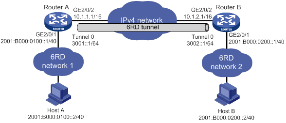
Requirements analysis
To enable communication between 6RD networks, you must perform the following tasks in addition to the 6RD tunnel configuration:
· On Router A and Router B, configure the 6RD prefix as 2001:B000::/32, the IPv4 prefix length as 16, and the IPv4 suffix length as 8.
· Configure 6RD addresses for the routers and hosts.
? On Router A, the tunnel source IPv4 address is 10.1.1.1/16, the IPv4 address of GigabitEthernet 2/0/2. Calculated based on this IPv4 address, the 6RD prefix, and the IPv4 prefix and suffix lengths, the 6RD delegated prefix for 6RD network 1 is 2001:B000:100::/40. The 6RD addresses of Router A and Host A must use this prefix.
? On Router B, the tunnel source IPv4 address is 10.1.2.1/16, the IPv4 address of GigabitEthernet 2/0/2. Calculated based on this IPv4 address, the 6RD prefix, and the IPv4 prefix and suffix lengths, the 6RD delegated prefix for 6RD network 2 is 2001:B000:200::/40. The 6RD addresses of Router B and Host B must use this prefix.
Configuration procedure
Make sure Router A and Router B can reach each other through IPv4.
· Configure Router A:
# Specify an IPv4 address for GigabitEthernet 2/0/2.
<RouterA> system-view
[RouterA] interface gigabitethernet 2/0/2
[RouterA-GigabitEthernet2/0/2] ip address 10.1.1.1 16
[RouterA-GigabitEthernet2/0/2] quit
# Specify a 6RD address for GigabitEthernet 2/0/1.
[RouterA] interface gigabitethernet 2/0/1
[RouterA-GigabitEthernet2/0/1] ipv6 address 2001:b000:0100::1/40
[RouterA-GigabitEthernet2/0/1] quit
# Create the 6RD tunnel interface Tunnel 0.
[RouterA] interface tunnel 0 mode ipv6-ipv4 6rd
# Specify an IPv6 address for the tunnel interface.
[RouterA-Tunnel0] ipv6 address 3001::1/64
# Specify the source interface as GigabitEthernet 2/0/2 for the tunnel interface.
[RouterA-Tunnel0] source gigabitethernet 2/0/2
# Configure the 6RD prefix for the tunnel interface.
[RouterA-Tunnel0] tunnel 6rd prefix 2001:b000::/32
# Specify a prefix length and a suffix length for the tunnel interface.
[RouterA-Tunnel0] tunnel 6rd ipv4 prefix-len 16 suffix-len 8
[RouterA-Tunnel0] quit
# Configure a static route destined for 2001:B000::/32 through the tunnel interface.
[RouterA] ipv6 route-static 2001:b000:: 32 tunnel 0
· Configure Router B:
# Specify an IPv4 address for GigabitEthernet 2/0/2.
<RouterB> system-view
[RouterB] interface gigabitethernet 2/0/2
[RouterB-GigabitEthernet2/0/2] ip address 10.1.2.1 16
[RouterB-GigabitEthernet2/0/2] quit
# Specify a 6RD address for GigabitEthernet 2/0/1.
[RouterB] interface gigabitethernet 2/0/1
[RouterB-GigabitEthernet2/0/1] ipv6 address 2001:b000:0200::1/40
[RouterB-GigabitEthernet2/0/1] quit
# Create the 6RD tunnel interface Tunnel 0.
[RouterB] interface tunnel 0 mode ipv6-ipv4 6rd
# Specify an IPv6 address for the tunnel interface.
[RouterB-Tunnel0] ipv6 address 3002::1/64
# Specify the source interface as GigabitEthernet 2/0/2 for the tunnel interface.
[RouterB-Tunnel0] source gigabitethernet 2/0/2
# Configure the 6RD prefix for the tunnel interface.
[RouterB-Tunnel0] tunnel 6rd prefix 2001:b000::/32
# Specify a prefix length and a suffix length for the tunnel interface.
[RouterB-Tunnel0] tunnel 6rd ipv4 prefix-len 16 suffix-len 8
[RouterB-Tunnel0] quit
# Configure a static route destined for 2001:B000::/32 through the tunnel interface.
[RouterB] ipv6 route-static 2001:b000:: 32 tunnel 0
Verifying the configuration
# Verify that Linux-running hosts Host A and Host B can ping each other.
D:\>ping6 -s 2001:b000:0100::2 2001:b000:0200::2
Pinging 2001:B000:0200::2
from 2001:B000:0100::2 with 32 bytes of data:
Reply from 2001:B000:0200::2: bytes=32 time=13ms
Reply from 2001:B000:0200::2: bytes=32 time=1ms
Reply from 2001:B000:0200::2: bytes=32 time=1ms
Reply from 2001:B000:0200::2: bytes=32 time<1ms
Ping statistics for 2001:B000:0200::2:
Packets: Sent = 4, Received = 4, Lost = 0 (0% loss),
Approximate round trip times in milli-seconds:
Minimum = 0ms, Maximum = 13ms, Average = 3ms
6RD relay configuration example
Network requirements
As shown in Figure 135, Host A is in a 6RD network connected to Router A (a 6RD CE). Host B is in a common IPv6 network connected to Router B (a 6RD BR router). Configure a 6RD tunnel between Router A and Router B to make Host A and Host B reachable to each other.
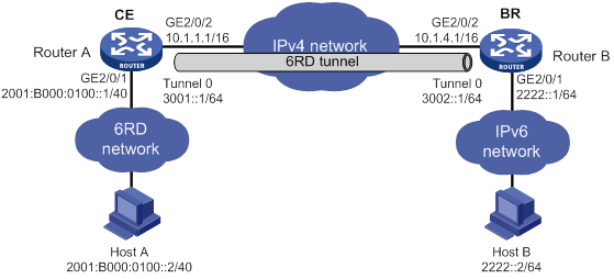
Requirements analysis
To enable communication between the 6RD network and the IPv6 network, you must perform the following tasks in addition to the 6RD tunnel configuration:
· On Router A and Router B, configure the 6RD prefix as 2001:B000::/32, the IPv4 prefix length as 16, and the IPv4 suffix length as 8.
· Configure 6RD addresses for Router A and Host A in the 6RD network.
On Router A, the tunnel source IPv4 address is 10.1.1.1/16, the IPv4 address of GigabitEthernet 2/0/2. Calculated based on this IPv4 address, the 6RD prefix, and the IPv4 prefix and suffix lengths, the 6RD delegated prefix for 6RD network 1 is 2001:B000:100::/40. The 6RD addresses of Router A and Host A must use this prefix.
· On Router A, you must configure a static route to the IPv6 network. The next hop address of the route is a 6RD address of Router B.
On Router B, the tunnel source IPv4 address is 10.1.4.1/16, the IPv4 address of GigabitEthernet 2/0/2. Calculated based on this IPv4 address, the 6RD prefix, and the IPv4 prefix and suffix lengths, the 6RD delegated prefix is 2001:B000:0400::/40. The next hop address of the static route can be any address using this prefix.
Configuration procedure
Make sure Router A and Router B can reach each other through IPv4.
· Configure Router A:
# Specify an IPv4 address for GigabitEthernet 2/0/2.
<RouterA> system-view
[RouterA] interface gigabitethernet 2/0/2
[RouterA-GigabitEthernet2/0/2] ip address 10.1.1.1 16
[RouterA-GigabitEthernet2/0/2] quit
# Specify a 6RD address for GigabitEthernet 2/0/1.
[RouterA] interface gigabitethernet 2/0/1
[RouterA-GigabitEthernet2/0/1] ipv6 address 2001:b000:0100::1/40
[RouterA-GigabitEthernet2/0/1] quit
# Create the 6RD tunnel interface Tunnel 0.
[RouterA] interface tunnel 0 mode ipv6-ipv4 6rd
# Specify an IPv6 address for the tunnel interface.
[RouterA-Tunnel0] ipv6 address 3001::1/64
# Specify the source interface as GigabitEthernet 2/0/2 for the tunnel interface.
[RouterA-Tunnel0] source gigabitethernet 2/0/2
# Configure the 6RD prefix for the tunnel interface.
[RouterA-Tunnel0] tunnel 6rd prefix 2001:b000::/32
# Specify a prefix length and a suffix length for the tunnel interface.
[RouterA-Tunnel0] tunnel 6rd ipv4 prefix-len 16 suffix-len 8
# Specify the BR address on the tunnel interface.
[RouterA-Tunnel0] tunnel 6rd br 10.1.4.1
[RouterA-Tunnel0] quit
# Configure a default route to reach the IPv6 network, which specifies the next hop as the 6RD address of Router B.
[RouterA] ipv6 route-static :: 0 2001:b000:0400::1
# Configure a static route destined for 2001:B000::/32 through the tunnel interface.
[RouterA] ipv6 route-static 2001:b000:: 32 tunnel 0
· Configure Router B:
# Specify an IPv4 address for GigabitEthernet 2/0/2.
<RouterB> system-view
[RouterB] interface gigabitethernet 2/0/2
[RouterB-GigabitEthernet2/0/2] ip address 10.1.4.1 16
[RouterB-GigabitEthernet2/0/2] quit
# Specify an IPv6 address for GigabitEthernet 2/0/1.
[RouterB] interface gigabitethernet 2/0/1
[RouterB-GigabitEthernet2/0/1] ipv6 address 2222::1/64
[RouterB-GigabitEthernet2/0/1] quit
# Create the 6RD tunnel interface Tunnel 0.
[RouterB] interface tunnel 0 mode ipv6-ipv4 6rd
# Specify an IPv6 address for the tunnel interface.
[RouterB-Tunnel0] ipv6 address 3002::1/64
# Specify the source interface as GigabitEthernet 2/0/2 for the tunnel interface.
[RouterB-Tunnel0] source gigabitethernet 2/0/2
# Configure the 6RD prefix for the tunnel interface.
[RouterB-Tunnel0] tunnel 6rd prefix 2001:b000::/32
# Specify a prefix length and a suffix length for the tunnel interface.
[RouterB-Tunnel0] tunnel 6rd ipv4 prefix-len 16 suffix-len 8
[RouterB-Tunnel0] quit
# Configure a static route destined for 2001:B000::/32 through the tunnel interface.
[RouterB] ipv6 route-static 2001:b000:: 32 tunnel 0
Verifying the configuration
# Verify that Linux-running hosts Host A and Host B can ping each other.
D:\>ping6 -s 2001:b000:0100::2 2222::2
Pinging 2001::2
from 2001:B000:0100::2 with 32 bytes of data:
Reply from 2222::2: bytes=32 time=13ms
Reply from 2222::2: bytes=32 time=1ms
Reply from 2222::2: bytes=32 time=1ms
Reply from 2222::2: bytes=32 time<1ms
Ping statistics for 2222::2:
Packets: Sent = 4, Received = 4, Lost = 0 (0% loss),
Approximate round trip times in milli-seconds:
Minimum = 0ms, Maximum = 13ms, Average = 3ms
Configuring an IPv4 over IPv4 tunnel
Configuration restrictions and guidelines
Follow these guidelines when you configure an IPv4 over IPv4 tunnel:
· The tunnel destination address specified on the local device must be identical with the tunnel source address specified on the tunnel peer device.
· Do not specify the same source and destination addresses for local tunnel interfaces in the same tunnel mode.
· The IPv4 address of the local tunnel interface cannot be on the same subnet as the destination address configured on the tunnel interface.
· To ensure correct packet forwarding, identify whether the destination IPv4 network and the IPv4 address of the local tunnel interface are on the same subnet. If they are not, configure a route reaching the destination IPv4 network through the tunnel interface. You can configure the route by using one of the following methods:
? Configure a static route, and specify the local tunnel interface as the egress interface or specify the IPv4 address of the peer tunnel interface as the next hop.
? Enable a dynamic routing protocol on both tunnel interfaces to achieve the same purpose.
For more information about route configuration, see Layer 3—IP Routing Configuration Guide.
· The destination address of the route passing the tunnel interface cannot be on the same subnet as the destination address configured on the tunnel interface.
Configuration procedure
To configure an IPv4 over IPv4 tunnel:
|
Step |
Command |
Remarks |
|
1. Enter system view. |
system-view |
N/A |
|
2. Enter IPv4 over IPv4 tunnel interface view. |
interface tunnel number [ mode ipv4-ipv4 ] |
N/A |
|
3. Configure an IPv4 address for the tunnel interface. |
ip address ip-address { mask | mask-length } [ sub ] |
By default, no IPv4 address is configured for the tunnel interface. |
|
4. Configure a source address or source interface for the tunnel interface. |
source { ipv4-address | interface-type interface-number } |
By default, no source address or source interface is configured for the tunnel interface. If you specify a source address, it is used as the source IP address of tunneled packets. If you specify a source interface, the primary IP address of this interface is used as the source IP address of tunneled packets. |
|
5. Configure a destination address for the tunnel interface. |
destination ipv4-address |
By default, no destination address is configured for the tunnel interface. The tunnel destination address must be the IP address of the receiving interface on the tunnel peer. It is used as the destination IP address of tunneled packets. |
|
6. (Optional.) Set the DF bit for tunneled packets. |
tunnel dfbit enable |
By default, the DF bit is not set for tunneled packets. |
Configuration example
Network requirements
As shown in Figure 136, the two subnets IPv4 group 1 and IPv4 group 2 use private IPv4 addresses. Configure an IPv4 over IPv4 tunnel between Router A and Router B to make the two subnets reachable to each other.
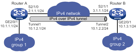
Configuration procedure
Make sure Router A and Router B can reach each other through IPv4.
· Configure Router A:
# Specify an IPv4 address for GigabitEthernet 2/0/1.
<RouterA> system-view
[RouterA] interface gigabitethernet 2/0/1
[RouterA-GigabitEthernet2/0/1] ip address 10.1.1.1 255.255.255.0
[RouterA-GigabitEthernet2/0/1] quit
# Specify an IPv4 address for Serial 2/1/0, which is the physical interface of the tunnel.
[RouterA] interface serial 2/1/0
[RouterA-Serial2/1/0] ip address 2.1.1.1 255.255.255.0
[RouterA-Serial2/1/0] quit
# Create the IPv4 over IPv4 tunnel interface Tunnel 1.
[RouterA] interface tunnel 1 mode ipv4-ipv4
# Specify an IPv4 address for the tunnel interface.
[RouterA-Tunnel1] ip address 10.1.2.1 255.255.255.0
# Specify the IP address of Serial 2/1/0 as the source address for the tunnel interface.
[RouterA-Tunnel1] source 2.1.1.1
# Specify the IP address of Serial 2/1/1 on Router B as the destination address for the tunnel interface.
[RouterA-Tunnel1] destination 3.1.1.1
[RouterA-Tunnel1] quit
# Configure a static route destined for IPv4 group 2 through the tunnel interface.
[RouterA] ip route-static 10.1.3.0 255.255.255.0 tunnel 1
· Configure Router B:
# Specify an IPv4 address for GigabitEthernet 2/0/1.
<RouterB> system-view
[RouterB] interface gigabitethernet 2/0/1
[RouterB-GigabitEthernet2/0/1] ip address 10.1.3.1 255.255.255.0
[RouterB-GigabitEthernet2/0/1] quit
# Specify an IPv4 address for Serial 2/1/1, which is the physical interface of the tunnel.
[RouterB] interface serial 2/1/1
[RouterB-Serial2/1/1] ip address 3.1.1.1 255.255.255.0
[RouterB-Serial2/1/1] quit
# Create the IPv4 over IPv4 tunnel interface Tunnel 2.
[RouterB] interface tunnel 2 mode ipv4-ipv4
# Specify an IPv4 address for the tunnel interface.
[RouterB-Tunnel2] ip address 10.1.2.2 255.255.255.0
# Specify the IP address of Serial 2/1/1 as the source address for the tunnel interface.
[RouterB-Tunnel2] source 3.1.1.1
# Specify the IP address of Serial 2/1/0 on Router A as a destination address for the tunnel interface.
[RouterB-Tunnel2] destination 2.1.1.1
[RouterB-Tunnel2] quit
# Configure a static route destined for IPv4 group 1 through the tunnel interface.
[RouterB] ip route-static 10.1.1.0 255.255.255.0 tunnel 2
Verifying the configuration
# Use the display interface tunnel command to display the status of the tunnel interfaces on Router A and Router B. Verify that the tunnel interfaces are up. (Details not shown.)
# Verify that Router A and Router B can ping the IPv4 address of the peer interface GigabitEthernet 2/0/1. This example uses Router A.
[RouterA] ping -a 10.1.1.1 10.1.3.1
Ping 10.1.3.1 (10.1.3.1) from 10.1.1.1: 56 data bytes, press CTRL_C to break
56 bytes from 10.1.3.1: icmp_seq=0 ttl=255 time=2.000 ms
56 bytes from 10.1.3.1: icmp_seq=1 ttl=255 time=1.000 ms
56 bytes from 10.1.3.1: icmp_seq=2 ttl=255 time=0.000 ms
56 bytes from 10.1.3.1: icmp_seq=3 ttl=255 time=1.000 ms
56 bytes from 10.1.3.1: icmp_seq=4 ttl=255 time=1.000 ms
--- Ping statistics for 10.1.3.1 ---
5 packet(s) transmitted, 5 packet(s) received, 0.0% packet loss
round-trip min/avg/max/std-dev = 0.000/1.000/2.000/0.632 ms
Configuring an IPv4 over IPv6 manual tunnel
Configuration restrictions and guidelines
Follow these guidelines when you configure an IPv4 over IPv6 manual tunnel:
· The tunnel destination address specified on the local device must be identical with the tunnel source address specified on the tunnel peer device.
· Do not specify the same source and destination addresses for local tunnel interfaces in the same tunnel mode.
· To ensure correct packet forwarding, identify whether the destination IPv4 network and the IPv4 address of the local tunnel interface are on the same subnet. If they are not, configure a route reaching the destination IPv4 network through the tunnel interface. You can configure the route by using one of the following methods:
? Configure a static route, and specify the local tunnel interface as the egress interface or specify the IPv6 address of the peer tunnel interface as the next hop.
? Enable a dynamic routing protocol on both tunnel interfaces to achieve the same purpose.
For more information about route configuration, see Layer 3—IP Routing Configuration Guide.
Configuration procedure
To configure an IPv4 over IPv6 manual tunnel:
|
Step |
Command |
Remarks |
|
1. Enter system view. |
system-view |
N/A |
|
2. Enter IPv6 tunnel interface view. |
interface tunnel number [ mode ipv6 ] |
N/A |
|
3. Configure an IPv4 address for the tunnel interface. |
ip address ip-address { mask | mask-length } [ sub ] |
By default, no IPv4 address is configured for the tunnel interface. |
|
4. Configure the source address or interface for the tunnel interface. |
source { ipv6-address | interface-type interface-number } |
By default, no source address or interface is configured for the tunnel. If you specify a source address, it is used as the source IPv6 address of tunneled packets. If you specify a source interface, the lowest IPv6 address of this interface is used as the source IPv6 address of tunneled packets. |
|
5. Configure the destination address for the tunnel interface. |
destination ipv6-address |
By default, no destination address is configured for the tunnel. The tunnel destination address must be the IPv6 address of the receiving interface on the tunnel peer. It is used as the destination IPv6 address of tunneled packets. |
Configuration example
Network requirements
As shown in Figure 137, configure an IPv4 over IPv6 manual tunnel between Router A and Router B so the two networks can reach each other over the IPv6 network.
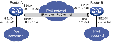
Configuration procedure
Make sure Router A and Router B can reach each other through IPv6.
· Configure Router A:
# Specify an IPv4 address for GigabitEthernet 2/0/1.
<RouterA> system-view
[RouterA] interface gigabitethernet 2/0/1
[RouterA-GigabitEthernet2/0/1] ip address 30.1.1.1 255.255.255.0
[RouterA-GigabitEthernet2/0/1] quit
# Specify an IPv6 address for Serial 2/1/0, which is the physical interface of the tunnel.
[RouterA] interface serial 2/1/0
[RouterA-Serial2/1/0] ipv6 address 2001::1:1 64
[RouterA-Serial2/1/0] quit
# Create the IPv6 tunnel interface Tunnel 1.
[RouterA] interface tunnel 1 mode ipv6
# Specify an IPv4 address for the tunnel interface.
[RouterA-Tunnel1] ip address 30.1.2.1 255.255.255.0
# Specify the IP address of Serial 2/1/0 as the source address for the tunnel interface.
[RouterA-Tunnel1] source 2001::1:1
# Specify the IP address of Serial 2/1/1 on Router B as the destination address for the tunnel interface.
[RouterA-Tunnel1] destination 2002::2:1
[RouterA-Tunnel1] quit
# Configure a static route destined for IPv4 network 2 through the tunnel interface.
[RouterA] ip route-static 30.1.3.0 255.255.255.0 tunnel 1
· Configure Router B:
# Specify an IPv4 address for GigabitEthernet 2/0/1.
<RouterB> system-view
[RouterB] interface gigabitethernet 2/0/1
[RouterB-GigabitEthernet2/0/1] ip address 30.1.3.1 255.255.255.0
[RouterB-GigabitEthernet2/0/1] quit
# Specify an IPv6 address for Serial 2/1/1, which is the physical interface of the tunnel.
[RouterB] interface serial 2/1/1
[RouterB-Serial2/1/1] ipv6 address 2002::2:1 64
[RouterB-Serial2/1/1] quit
# Create the IPv6 tunnel interface Tunnel 2.
[RouterB] interface tunnel 2 mode ipv6
# Specify an IPv4 address for the tunnel interface.
[RouterB-Tunnel2] ip address 30.1.2.2 255.255.255.0
# Specify the IP address of Serial 2/1/1 as the source address for the tunnel interface.
[RouterB-Tunnel2] source 2002::2:1
# Specify the IP address of Serial 2/1/0 on Router A as the destination address for the tunnel interface.
[RouterB-Tunnel2] destination 2001::1:1
[RouterB-Tunnel2] quit
# Configure a static route destined for IPv4 network 1 through the tunnel interface.
[RouterB] ip route-static 30.1.1.0 255.255.255.0 tunnel 2
Verifying the configuration
# Use the display interface tunnel command to display the status of the tunnel interfaces on Router A and Router B. Verify that the tunnel interfaces are up. (Details not shown.)
# Verify that Router A and Router B can ping the IPv4 address of the peer interface GigabitEthernet 2/0/1. This example uses Router A.
[RouterA] ping -a 30.1.1.1 30.1.3.1
Ping 30.1.3.1 (30.1.3.1) from 30.1.1.1: 56 data bytes, press CTRL_C to break
56 bytes from 30.1.3.1: icmp_seq=0 ttl=255 time=3.000 ms
56 bytes from 30.1.3.1: icmp_seq=1 ttl=255 time=1.000 ms
56 bytes from 30.1.3.1: icmp_seq=2 ttl=255 time=0.000 ms
56 bytes from 30.1.3.1: icmp_seq=3 ttl=255 time=1.000 ms
56 bytes from 30.1.3.1: icmp_seq=4 ttl=255 time=1.000 ms
--- Ping statistics for 30.1.3.1 ---
5 packet(s) transmitted, 5 packet(s) received, 0.0% packet loss
round-trip min/avg/max/std-dev = 0.000/1.200/3.000/0.980 ms
Configuring a DS-Lite tunnel
Configuration restrictions and guidelines
A B4 tunnel interface can establish a tunnel with only one AFTR tunnel interface, but an AFTR tunnel interface can establish tunnels with multiple B4 tunnel interfaces.
Follow these guidelines when you configure the B4 router of a DS-Lite tunnel:
· Do not specify the same source addresses for local tunnel interfaces in the same tunnel mode.
· The destination address specified for the tunnel interface on the B4 router must be the source address specified for the tunnel interface on the AFTR.
· To ensure correct packet forwarding, identify whether the destination IPv4 network and the IPv4 address of the local tunnel interface are on the same subnet. If they are not, configure a route reaching the destination IPv4 network through the tunnel interface. You can configure the route by using one of the following methods:
? Configure a static route, and specify the local tunnel interface as the egress interface or specify the IPv6 address of the peer tunnel interface as the next hop.
? Enable a dynamic routing protocol on both tunnel interfaces to achieve the same purpose.
For more information about route configuration, see Layer 3—IP Routing Configuration Guide.
Follow these guidelines when you configure the AFTR of a DS-Lite tunnel:
· Do not specify the same source addresses for local tunnel interfaces in the same tunnel mode.
· Enable NAT on the interface that is connected to the public IPv4 interface.
· The tunnel destination cannot be configured on the AFTR. The AFTR uses the address of the B4 router as the IPv6 address of the tunnel destination.
· It is not necessary to configure a route to the destination IPv4 address for forwarding packets through the tunnel interface.
Configuration procedure
To configure the B4 router of a DS-Lite tunnel:
|
Step |
Command |
Remarks |
|
1. Enter system view. |
system-view |
N/A |
|
2. Enter IPv6 tunnel interface view. |
interface tunnel number [ mode ipv6 ] |
N/A |
|
3. Specify an IPv4 address for the tunnel interface. |
ip address ip-address { mask | mask-length } [ sub ] |
By default, no IPv4 address is specified for the tunnel interface. |
|
4. Specify the source address or source interface for the tunnel. |
source { ipv6-address | interface-type interface-number } |
By default, no source address or interface is specified for the tunnel. If you specify a source address, it is used as the source IPv6 address of tunneled packets. If you specify a source interface, the lowest IPv6 address of this interface is used as the source IPv6 address of tunneled packets. |
|
5. Specify the destination address for the tunnel. |
destination ipv6-address |
By default, no destination address is configured for the tunnel. The tunnel destination address must be the IPv6 address of the receiving interface on the tunnel peer. It is used as the destination IPv6 address of tunneled packets. |
To configure the AFTR of a DS-Lite tunnel:
|
Step |
Command |
Remarks |
|
1. Enter system view. |
system-view |
N/A |
|
2. Enter the view of the tunnel interface on the AFTR. |
interface tunnel number [ mode ds-lite-aftr ] |
N/A |
|
3. Specify an IPv4 address for the tunnel interface. |
ip address ip-address { mask | mask-length } [ sub ] |
By default, no IPv4 address is specified for the tunnel interface. |
|
4. Specify the source address or source interface for the tunnel. |
source { ipv6-address | interface-type interface-number } |
By default, no source address or interface is specified for the tunnel. The specified source address or the lowest IPv6 address of the specified source interface is used as the source IPv6 address of tunneled packets. |
|
5. Return to system view. |
quit |
N/A |
|
6. Enter the view of the interface that is connected to the IPv4 public network. |
interface interface-type interface-number |
N/A |
|
7. Enable DS-Lite tunneling on the interface. |
ds-lite enable |
By default, DS-Lite tunneling is disabled. Only after you use this command, the AFTR can tunnel IPv4 packets from the public IPv4 network to the B4 router. |
Configuration example
Network requirements
As shown in Figure 138, to enable hosts in the private IPv4 network to access the public IPv4 network over the IPv6 network, perform the following tasks:
· Configure a DS-Lite tunnel between Router A and Router B.
· Configure NAT on GigabitEthernet 2/0/1 on the AFTR.
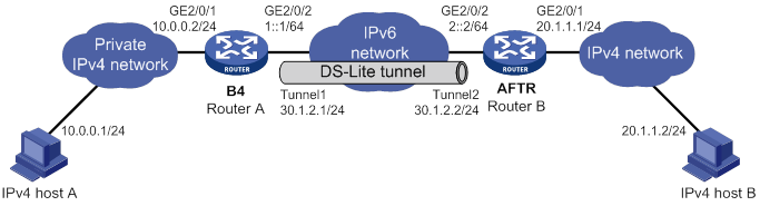
Configuration procedure
Make sure Router A and Router B can reach each other through IPv6.
· Configure Router A:
# Specify an IPv4 address for GigabitEthernet 2/0/1.
<RouterA> system-view
[RouterA] interface gigabitethernet 2/0/1
[RouterA-GigabitEthernet2/0/1] ip address 10.0.0.2 255.255.255.0
[RouterA-GigabitEthernet2/0/1] quit
# Specify an IPv6 address for GigabitEthernet 2/0/2, which is the physical interface of the tunnel.
[RouterA] interface gigabitethernet 2/0/2
[RouterA-GigabitEthernet2/0/2] ipv6 address 1::1 64
[RouterA-GigabitEthernet2/0/2] quit
# Create the IPv6 tunnel interface Tunnel 1.
[RouterA] interface tunnel 1 mode ipv6
# Specify an IPv4 address for the tunnel interface.
[RouterA-Tunnel1] ip address 30.1.2.1 255.255.255.0
# Specify the IP address of GigabitEthernet 2/0/2 as the source address for the tunnel interface.
[RouterA-Tunnel1] source 1::1
# Specify IP address of GigabitEthernet 2/0/2 on Router B as the destination address for the tunnel interface.
[RouterA-Tunnel1] destination 2::2
[RouterA-Tunnel1] quit
# Configure a static route to the public IPv4 network through the tunnel interface.
[RouterA] ip route-static 20.1.1.0 255.255.255.0 tunnel 1
· Configure Router B:
# Specify an IPv4 address for GigabitEthernet 2/0/1.
<RouterB> system-view
[RouterB] interface gigabitethernet 2/0/1
[RouterB-GigabitEthernet2/0/1] ip address 20.1.1.1 24
[RouterB-GigabitEthernet2/0/1] quit
# Specify an IPv6 address for GigabitEthernet 2/0/2, which is the physical interface of the tunnel.
[RouterB] interface gigabitethernet 2/0/2
[RouterB-GigabitEthernet2/0/2] ipv6 address 2::2 64
[RouterB-GigabitEthernet2/0/2] quit
# Create the DS-Lite tunnel interface Tunnel 2.
[RouterB] interface tunnel 2 mode ds-lite-aftr
# Configure an IPv4 address for the tunnel interface.
[RouterB-Tunnel2] ip address 30.1.2.2 255.255.255.0
# Specify GigabitEthernet 2/0/2 as the source interface of the tunnel interface.
[RouterB-Tunnel2] source gigabitethernet 2/0/2
[RouterB-Tunnel2] quit
# Enable DS-Lite tunneling on GigabitEthernet 2/0/1.
[RouterB] interface gigabitethernet 2/0/1
[RouterB-GigabitEthernet2/0/1] ds-lite enable
# Enable NAT on GigabitEthernet 2/0/1 and use the IP address of GigabitEthernet 2/0/1 as the translated address.
[RouterB-GigabitEthernet2/0/1] nat outbound
[RouterB-GigabitEthernet2/0/1] quit
· On host A, specify the IP address for the host as 10.0.0.1 and configure a static route to 20.1.1.0/24 with next hop 10.0.0.2. (Details not shown.)
· On host B, specify the IP address for the host as 20.1.1.2. (Details not shown.)
Verifying the configuration
# Use the display interface tunnel command to display the status of the tunnel interfaces on Router A and Router B. Verify that the tunnel interfaces are up. (Details not shown.)
# Verify that host A can ping host B.
C:\> ping 20.1.1.2
Pinging 20.1.1.2 with 32 bytes of data:
Reply from 20.1.1.2: bytes=32 time=51ms TTL=255
Reply from 20.1.1.2: bytes=32 time=44ms TTL=255
Reply from 20.1.1.2: bytes=32 time=1ms TTL=255
Reply from 20.1.1.2: bytes=32 time=1ms TTL=255
Ping statistics for 20.1.1.2:
Packets: Sent = 4, Received = 4, Lost = 0 (0% loss),
Approximate round trip times in milli-seconds:
Minimum = 1ms, Maximum = 51ms, Average = 24ms
Configuring an IPv6 over IPv6 tunnel
Configuration restrictions and guidelines
Follow these guidelines when you configure an IPv6 over IPv6 tunnel:
· The tunnel destination address specified on the local device must be identical with the tunnel source address specified on the tunnel peer device.
· Do not specify the same source and destination addresses for local tunnel interfaces in the same tunnel mode.
· The IPv6 address of the tunnel interface cannot be on the same subnet as the destination address configured for the tunnel interface.
· To ensure correct packet forwarding, identify whether the destination IPv6 network and the IPv6 address of the local tunnel interface are on the same subnet. If they are not, configure a route reaching the destination IPv6 network through the tunnel interface. You can configure the route by using one of the following methods:
? Configure a static route, and specify the local tunnel interface as the egress interface or specify the IPv6 address of the peer tunnel interface as the next hop.
? Enable a dynamic routing protocol on both tunnel interfaces to achieve the same purpose.
For more information about route configuration, see Layer 3—IP Routing Configuration Guide.
· The destination address of the route passing the tunnel interface cannot be on the same subnet as the destination address configured for the tunnel interface.
Configuration procedure
To configure an IPv6 over IPv6 tunnel:
|
Step |
Command |
Remarks |
|
1. Enter system view. |
system-view |
N/A |
|
2. Enter IPv6 tunnel interface view. |
interface tunnel number [ mode ipv6 ] |
N/A |
|
3. Configure an IPv6 address for the tunnel interface. |
By default, no IPv6 address is configured for the tunnel interface. |
|
|
4. Configure the source address or source interface for the tunnel interface. |
source { ipv6-address | interface-type interface-number } |
By default, no source address or interface is configured for the tunnel. If you specify a source address, it is used as the source IPv6 address of tunneled packets. If you specify a source interface, the lowest IPv6 address of this interface is used as the source IPv6 address of tunneled packets. |
|
5. Configure the destination address for the tunnel interface. |
destination ipv6-address |
By default, no destination address is configured for the tunnel. The tunnel destination address must be the IPv6 address of the receiving interface on the tunnel peer. It is used as the destination IPv6 address of tunneled packets. |
|
6. (Optional.) Set the maximum number of nested encapsulations of a packet. |
encapsulation-limit number |
By default, there is no limit to the nested encapsulations of a packet. |
|
7. Return to system view. |
quit |
N/A |
|
8. (Optional.) Enable dropping IPv6 packets that use IPv4-compatible IPv6 addresses. |
tunnel discard ipv4-compatible-packet |
Support for this command depends on the device model. For more information about the command and hardware compatibility, see Layer 3—IP Services Command Reference. By default, IPv6 packets that use IPv4-compatible IPv6 packets are not dropped. |
Configuration example
Network requirements
As shown in Figure 139, configure an IPv6 over IPv6 tunnel between Router A and Router B so the two networks can reach each other without disclosing their IPv6 addresses.
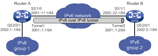
Configuration procedure
Make sure Router A and Router B can reach each other through IPv6.
· Configure Router A:
# Specify an IPv6 address for GigabitEthernet 2/0/1.
<RouterA> system-view
[RouterA] interface gigabitethernet 2/0/1
[RouterA-GigabitEthernet2/0/1] ipv6 address 2002:1::1 64
[RouterA-GigabitEthernet2/0/1] quit
# Specify an IPv6 address for Serial 2/1/0, which is the physical interface of the tunnel.
[RouterA] interface serial 2/1/0
[RouterA-Serial2/1/0] ipv6 address 2001::11:1 64
[RouterA-Serial2/1/0] quit
# Create the IPv6 tunnel interface Tunnel 1.
[RouterA] interface tunnel 1 mode ipv6
# Specify an IPv6 address for the tunnel interface.
[RouterA-Tunnel1] ipv6 address 3001::1:1 64
# Specify the IP address of Serial 2/1/0 as the source address for the tunnel interface.
[RouterA-Tunnel1] source 2001::11:1
# Specify the IP address of Serial 2/1/1 on Router B as the destination address for the tunnel interface.
[RouterA-Tunnel1] destination 2002::22:1
[RouterA-Tunnel1] quit
# Configure a static route destined for the IPv6 network group 2 through the tunnel interface.
[RouterA] ipv6 route-static 2002:3:: 64 tunnel 1
· Configure Router B:
# Specify an IPv6 address for GigabitEthernet 2/0/1.
<RouterB> system-view
[RouterB] interface gigabitethernet 2/0/1
[RouterB-GigabitEthernet2/0/1] ipv6 address 2002:3::1 64
[RouterB-GigabitEthernet2/0/1] quit
# Specify an IPv6 address for Serial 2/1/1, which is the physical interface of the tunnel.
[RouterB] interface serial 2/1/1
[RouterB-Serial2/1/1] ipv6 address 2002::22:1 64
[RouterB-Serial2/1/1] quit
# Create the IPv6 tunnel interface Tunnel 2.
[RouterB] interface tunnel 2 mode ipv6
# Specify an IPv6 address for the tunnel interface.
[RouterB-Tunnel2] ipv6 address 3001::1:2 64
# Specify the IP address of Serial 2/1/1 as the source address for the tunnel interface.
[RouterB-Tunnel2] source 2002::22:1
# Specify the IP address of Serial 2/1/0 on Router A as the destination address for the tunnel interface.
[RouterB-Tunnel2] destination 2001::11:1
[RouterB-Tunnel2] quit
# Configure a static route destined for the IPv6 network group 1 through the tunnel interface.
[RouterB] ipv6 route-static 2002:1:: 64 tunnel 2
Verifying the configuration
# Use the display ipv6 interface command to display the status of the tunnel interfaces on Router A and Router B. Verify that the tunnel interfaces are up. (Details not shown.)
# Verify that Router A and Router B can ping the IPv6 address of the peer interface GigabitEthernet 2/0/1. This example uses Router A.
[RouterA] ping ipv6 -a 2002:1::1 2002:3::1
Ping6(56 data bytes) 2002:1::1 --> 2002:3::1, press CTRL_C to break
56 bytes from 2002:3::1, icmp_seq=0 hlim=64 time=9.000 ms
56 bytes from 2002:3::1, icmp_seq=1 hlim=64 time=1.000 ms
56 bytes from 2002:3::1, icmp_seq=2 hlim=64 time=0.000 ms
56 bytes from 2002:3::1, icmp_seq=3 hlim=64 time=0.000 ms
56 bytes from 2002:3::1, icmp_seq=4 hlim=64 time=0.000 ms
--- Ping6 statistics for 2002:3::1 ---
5 packet(s) transmitted, 5 packet(s) received, 0.0% packet loss
round-trip min/avg/max/std-dev = 0.000/2.000/9.000/3.521 ms
Displaying and maintaining tunneling configuration
Execute display commands in any view and reset commands in user view.
|
Task |
Command |
|
Display information about 6RD tunnel interfaces. |
display 6rd [ interface tunnel number ] |
|
Display a 6RD tunnel destination address. |
display 6rd destination prefix ipv6-prefix interface tunnel number |
|
Display a 6RD delegated prefix. |
display 6rd prefix destination ipv4-address interface tunnel number |
|
Display information about tunnel interfaces. |
display interface [ tunnel [ number ] ] [ brief [ description | down ] ] |
|
Display IPv6 information on tunnel interfaces. |
display ipv6 interface [ tunnel [ number ] ] [ brief ] |
|
Display information about the connected B4 routers on the AFTR. |
display ds-lite b4 information |
|
Clear statistics on tunnel interfaces. |
reset counters interface [ tunnel [ number ] ] |
For more information about the display ipv6 interface command, see Layer 3—IP Services Command Reference.
Troubleshooting tunneling configuration
Symptom
A tunnel interface configured with related parameters such as tunnel source address, tunnel destination address, and tunnel mode cannot come up.
Analysis
The physical interface of the tunnel does not come up, or the tunnel destination is unreachable.
Solution
1. To resolve the problem:
? Use the display interface or display ipv6 interface command to verify that the physical interface of the tunnel is up. If the physical interface is down, check the network connection.
? Use the display ipv6 routing-table or display ip routing-table command to verify that the tunnel destination is reachable. If the route is not available, configure a route to reach the tunnel destination.
2. If the problem persists, contact H3C Support.
Configuring GRE
Overview
GRE encapsulation format
Figure 140 GRE encapsulation format
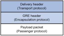
As shown in Figure 140, a GRE-tunneled packet includes the following parts:
· Payload packet—Original packet. The protocol type of the payload packet is called the passenger protocol. The passenger protocol can be any network layer protocol.
· GRE header—Header that is added to the payload packet to change the payload packet to a GRE packet. A GRE header includes the number of encapsulations, version, passenger protocol type, checksum, and key. GRE is called the encapsulation protocol.
· Delivery header—Header that is added to the GRE packet to deliver it to the tunnel end. The transport protocol (or delivery protocol) is the network layer protocol that transfers GRE packets.
The device supports GRE tunnels with IPv4 and IPv6 as the transport protocols. When the transport protocol is IPv4, the GRE tunnel mode is GRE over IPv4 (GRE/IPv4). When the transport protocol is IPv6, the GRE tunnel mode is GRE over IPv6 (GRE/IPv6).
GRE tunnel operating principle
Figure 141 IPv6 networks interconnected through a GRE tunnel
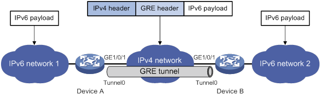
As shown in Figure 141, an IPv6 protocol packet traverses an IPv4 network through a GRE tunnel as follows:
1. After receiving an IPv6 packet from the interface connected to IPv6 network 1, Device A processes the packet as follows:
a. Looks up the routing table to identify the outgoing interface for the IPv6 packet.
b. Submits the IPv6 packet to the outgoing interface—the GRE tunnel interface Tunnel 0.
2. Upon receiving the packet, the tunnel interface encapsulates the packet with GRE and then with IPv4. In the IPv4 header:
? The source address is the tunnel's source address (the IP address of interface GigabitEthernet 1/0/1 of Device A).
? The destination address is the tunnel's destination address (the IP address of interface GigabitEthernet 1/0/1 of Device B).
3. Device A looks up the routing table according to the destination address in the IPv4 header, and forwards the IPv4 packet out of the physical interface (GigabitEthernet 1/0/1) of the GRE tunnel.
4. When the IPv4 arrives at the GRE tunnel destination Device B, Device B checks the destination address. Because the destination is Device B itself and the protocol number in the IP header is 47 (the protocol number for GRE), Device B submits the packet to GRE for de-encapsulation.
5. GRE first removes the IPv4 header, and then checks the GRE key, checksum, and packet sequence number. After GRE finishes the checking, it removes the GRE header, and submits the payload to the IPv6 protocol for forwarding.
|
|
NOTE: GRE encapsulation and de-encapsulation can decrease the forwarding efficiency of tunnel-end devices. |
GRE security mechanisms
GRE supports the following security mechanisms:
· GRE key—Ensures packet validity. The sender adds a GRE key into a packet. The receiver compares the GRE key with its own GRE key. If the two keys are the same, the receiver accepts the packet. If the two keys are different, the receiver drops the packet.
· GRE checksum—Ensures packet integrity. The sender calculates a checksum for the GRE header and payload and sends the packet containing the checksum to the tunnel peer. The receiver calculates a checksum for the received packet and compares it with that carried in the packet. If the checksums are the same, the receiver considers the packet intact and continues to process the packet. If the checksums are different, the receiver discards the packet.
GRE application scenarios
The following shows typical GRE application scenarios:
Connecting networks running different protocols over a single backbone
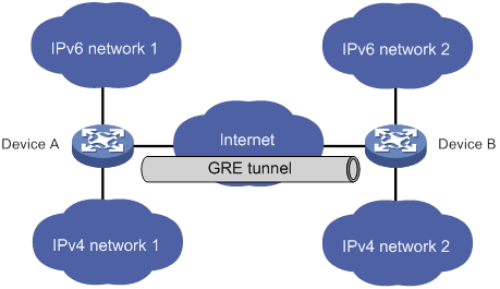
As shown in Figure 142, IPv6 network 1 and IPv6 network 2 are IPv6 networks, and IPv4 network 1 and IPv4 network 2 are IPv4 networks. Through the GRE tunnel between Device A and Device B, IPv6 network 1 can communicate with IPv6 network 2 and IPv4 network 1 can communicate with IPv4 network 2, without affecting each other.
Enlarging network scope
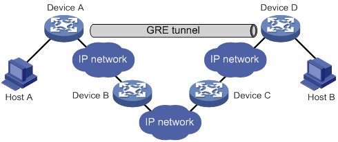
In an IP network, the maximum TTL value of a packet is 255. If two devices have more than 255 hops in between, they cannot communicate with each other. By using a GRE tunnel, you can hide some hops to enlarge the network scope. As shown in Figure 143, only the tunnel-end devices (Device A and Device D) of the GRE tunnel are counted in hop count calculation. Therefore, there are only three hops between Host A and Host B.
Constructing VPN
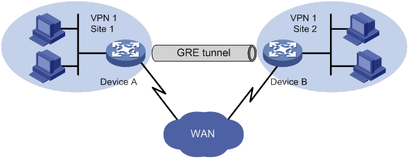
As shown in Figure 144, Site 1 and Site 2 both belong to VPN 1 and are located in different cities. Using a GRE tunnel can connect the two VPN sites across the WAN.
Operating with IPsec
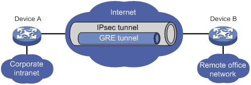
As shown in Figure 145, GRE can be used together with IPsec to form a GRE over IPsec tunnel. Packets (for example, routing protocol packets, voice data, and video data) are first encapsulated with GRE and then with IPsec. GRE over IPsec delivers the following benefits:
· Improves transmission security.
· Allows IPsec to protect not only unicast packets. GRE supports encapsulating multicast, broadcast, and non-IP packets. After GRE encapsulation, these packets become common unicast packets, which can be protected by IPsec.
· Simplifies IPsec configuration. Packets are first encapsulated by GRE. You can define the packets to be protected by IPsec according to the GRE tunnel's source and destination addresses, without considering the source and destination addresses of the original packets.
GRE and IPsec can also form IPsec over GRE tunnels. As a best practice, use GRE over IPsec tunnels instead of IPsec over GRE tunnels.
For more information about IPsec, see Security Configuration Guide.
Protocols and standards
· RFC 1701, Generic Routing Encapsulation (GRE)
· RFC 1702, Generic Routing Encapsulation over IPv4 networks
· RFC 2784, Generic Routing Encapsulation (GRE)
· RFC 2890, Key and Sequence Number Extensions to GRE
Configuring a GRE/IPv4 tunnel
Perform this task to configure a GRE tunnel on an IPv4 network.
Configuration guidelines
Follow these guidelines when you configure a GRE/IPv4 tunnel:
· As a best practice, do not configure the same tunnel source and destination addresses for local tunnel interfaces that use the same tunnel mode.
· You can enable or disable GRE checksum at each end of a tunnel. If GRE checksum is enabled at a tunnel end, the tunnel end sends packets carrying the checksum to the peer end. A tunnel end checks the GRE checksum of a received packet if the packet carries a GRE checksum, whether or not the tunnel end is enabled with GRE checksum.
· To ensure correct packet forwarding, identify whether the destination network of packets and the IP address of the local tunnel interface are on the same subnet. If they are not, configure a route reaching the destination network through the tunnel interface. You can configure the route by using one of the following methods:
? Configure a static route, using the local tunnel interface as the outgoing interface of the route.
? Enable a dynamic routing protocol on both the tunnel interface and the interface connecting the private network. This allows the dynamic routing protocol to establish a routing entry with the tunnel interface as the outgoing interface.
· The IP address of the tunnel interface and the tunnel destination address configured on the tunnel interface must be in different subnets.
For information about tunnel interfaces, and the interface tunnel, source, destination, tunnel dfbit enable, and tunnel discard ipv4-compatible-packet commands, see "Configuring tunneling."
Configuration procedure
To configure a GRE/IPv4 tunnel:
|
Step |
Command |
Remarks |
|
1. Enter system view. |
system-view |
N/A |
|
2. Create a GRE tunnel interface, and specify the tunnel mode as GRE/IPv4. |
interface tunnel interface-number mode gre |
By default, no tunnel interfaces exist. You must configure the same tunnel mode on both ends of a tunnel. Otherwise, packet delivery might fail. |
|
3. Configure an IPv4 or IPv6 address for the tunnel interface. |
For information about how to assign an IPv4 address to an interface, see "Configuring IP addressing." For information about how to assign an IPv6 address to an interface, see "Configuring basic IPv6 settings." |
By default, no IPv4 or IPv6 address is configured for a tunnel interface. When the passenger protocol is IPv4, configure an IPv4 address for the tunnel interface. When the passenger protocol is IPv6, configure an IPv6 address for the tunnel interface. |
|
4. Configure a source address or source interface for the tunnel interface. |
source { ip-address | interface-type interface-number } |
By default, no source address or interface is configured for a tunnel interface. If you configure a source address for a tunnel interface, the tunnel interface uses the source address as the source address of the encapsulated packets. If you configure a source interface for a tunnel interface, the tunnel interface uses the primary IP address of the source interface as the source address of the encapsulated packets. |
|
5. Configure a destination address for the tunnel interface. |
destination ip-address |
By default, no destination address is configured for a tunnel interface. The destination address is the address of the physical interface that the tunnel remote end uses to receive packets from the GRE tunnel. The tunnel local end uses this address as the destination address of the encapsulated packets. |
|
6. (Optional.) Enable GRE keepalive, and set the keepalive interval and keepalive number. |
keepalive [ interval [ times ] ] |
By default, GRE keepalive is disabled. |
|
7. (Optional.) Enable GRE checksum. |
gre checksum |
By default, GRE checksum is disabled. |
|
8. (Optional.) Configure a GRE key for the GRE tunnel interface. |
gre key key |
By default, no GRE key is configured for a GRE tunnel interface. The two ends of a GRE tunnel must have the same key or both have no key. |
|
9. (Optional.) Set the DF bit for encapsulated packets. |
tunnel dfbit enable |
By default, the DF bit is not set, allowing encapsulated packets to be fragmented. |
|
10. (Optional.) Specify a service class value for the GRE tunnel interface. |
service-class service-class-value |
By default, no service class value is specified for a GRE tunnel interface. |
|
11. Return to system view. |
quit |
N/A |
|
12. (Optional.) Configure the device to discard IPv6 packets with IPv4-compatible IPv6 addresses. |
tunnel discard ipv4-compatible-packet |
Support for this command depends on the device model. For more information about the command and hardware compatibility, see Layer 3—IP Services Command Reference. By default, the device does not discard such IPv6 packets. |
Configuring a GRE/IPv6 tunnel
Perform this task to configure a GRE tunnel on an IPv6 network.
Configuration guidelines
Follow these guidelines when you configure a GRE/IPv6 tunnel:
· You must configure the tunnel source address and destination address at both ends of a tunnel. The tunnel source or destination address at one end must be the tunnel destination or source address at the other end.
· As a best practice, do not configure the same tunnel source and destination addresses for local tunnel interfaces that use the same tunnel mode.
· You can enable or disable GRE checksum at each end of a tunnel. If GRE checksum is enabled at a tunnel end, the tunnel end sends packets carrying the checksum to the peer end. A tunnel end checks the GRE checksum of a received packet if the packet carries a GRE checksum, whether or not the tunnel end is enabled with GRE checksum.
· To ensure correct packet forwarding, identify whether the destination network of packets and the IP address of the local tunnel interface are on the same subnet. If they are not, configure a route reaching the destination network through the tunnel interface. You can configure the route by using the following methods:
? Configure a static route, using the local tunnel interface as the outgoing interface of the route.
? Enable a dynamic routing protocol on both the tunnel interface and the interface connecting the private network. This allows the dynamic routing protocol to establish a routing entry with the tunnel interface as the outgoing interface.
· The IP address of the tunnel interface and the tunnel destination address configured on the tunnel interface must be in different subnets.
For information about tunnel interfaces, the interface tunnel, source, destination, and tunnel discard ipv4-compatible-packet commands, and additional configuration commands on a tunnel interface, see "Configuring tunneling."
Configuration procedure
To configure a GRE/IPv6 tunnel:
|
Step |
Command |
Remarks |
|
1. Enter system view. |
system-view |
N/A |
|
2. Create a GRE tunnel interface, and specify the tunnel mode as GRE/IPv6. |
interface tunnel interface-number mode gre ipv6 |
By default, no tunnel interfaces exist. You must configure the same tunnel mode on both ends of a tunnel. Otherwise, packet delivery might fail. |
|
3. Configure an IPv4 or IPv6 address for the tunnel interface. |
For information about how to assign an IPv4 address to an interface, see "Configuring IP addressing." For information about how to assign an IPv6 address to an interface, see "Configuring basic IPv6 settings." |
By default, no IPv4 or IPv6 address is configured for a tunnel interface. When the passenger protocol is IPv4, configure an IPv4 address for the tunnel interface. When the passenger protocol is IPv6, configure an IPv6 address for the tunnel interface. |
|
4. Configure a source IPv6 address or source interface for the tunnel interface. |
source { ipv6-address | interface-type interface-number } |
By default, no source IPv6 address or interface is configured for a tunnel interface. If you configure a source IPv6 address for a tunnel interface, the tunnel interface uses the source IPv6 address as the source IPv6 address of the encapsulated packets. If you configure a source interface for a tunnel interface, the tunnel interface uses the IPv6 address of the source interface as the source IPv6 address of the encapsulated packets. |
|
5. Configure a destination IPv6 address for the tunnel interface. |
destination ipv6-address |
By default, no destination IPv6 address is configured for a tunnel interface. The destination IPv6 address is the IPv6 address of the physical interface that the tunnel remote end uses to receive packets from the GRE tunnel. The tunnel local end uses this address as the destination IPv6 address of the encapsulated packets. |
|
6. (Optional.) Enable GRE checksum. |
gre checksum |
By default, GRE checksum is disabled. |
|
7. (Optional.) Configure a GRE key for the tunnel interface. |
gre key key |
By default, no GRE key is configured for a GRE tunnel interface. The two ends of a GRE tunnel must have the same key or both have no key. |
|
8. (Optional.) Specify a service class value for the GRE tunnel interface. |
service-class service-class-value |
By default, no service class value is specified for a GRE tunnel interface. |
|
9. Return to system view. |
quit |
N/A |
|
10. (Optional.) Configure the device to discard IPv6 packets with IPv4-compatible IPv6 addresses |
tunnel discard ipv4-compatible-packet |
Support for this command depends on the device model. For more information about the command and hardware compatibility, see Layer 3—IP Services Command Reference. By default, the device does not discard such IPv6 packets. |
Displaying and maintaining GRE
Execute display commands in any view and reset commands in user view.
|
Task |
Command |
Remarks |
|
Display information about tunnel interfaces. |
display interface [ tunnel [ number ] ] [ brief [ description | down ] ] |
For more information about the commands, see Layer 3—IP Services Command Reference. |
|
Display IPv6 information about tunnel interface. |
display ipv6 interface [ tunnel [ number ] ] [ brief ] |
For more information about this command, see Layer 3—IP Services Command Reference. |
|
Clear tunnel interface statistics. |
reset counters interface [ tunnel [ number ] ] |
For more information about this command, see Layer 3—IP Services Command Reference. |
GRE configuration examples
Configuring an IPv4 over IPv4 GRE tunnel
Network requirements
As shown in Figure 146, Group 1 and Group 2 are two private IPv4 networks. The two networks both use private network addresses and belong to the same VPN. Establish a GRE tunnel between Router A and Router B to interconnect the two private IPv4 networks Group 1 and Group 2.
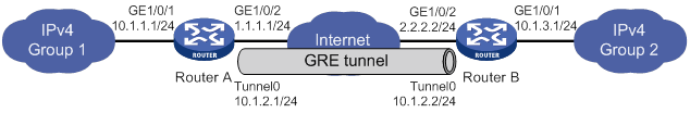
Configuration procedure
Before performing the following configuration, configure an IP address for each interface, and make sure Router A and Router B can reach each other.
1. Configure Router A:
# Create a tunnel interface Tunnel 0, and specify the tunnel mode as GRE/IPv4.
<RouterA> system-view
[RouterA] interface tunnel 0 mode gre
# Configure an IP address for the tunnel interface.
[RouterA-Tunnel0] ip address 10.1.2.1 255.255.255.0
# Configure the source address of the tunnel interface as the IP address of GigabitEthernet 1/0/2 on Router A.
[RouterA-Tunnel0] source 1.1.1.1
# Configure the destination address of the tunnel interface as the IP address of GigabitEthernet 1/0/2 on Router B.
[RouterA-Tunnel0] destination 2.2.2.2
[RouterA-Tunnel0] quit
# Configure a static route from Router A through the tunnel interface to Group 2.
[RouterA] ip route-static 10.1.3.0 255.255.255.0 tunnel 0
2. Configure Router B:
# Create tunnel interface Tunnel 0 and specify the tunnel mode as GRE/IPv4.
<RouterB> system-view
[RouterB] interface tunnel 0 mode gre
# Configure an IP address for the tunnel interface.
[RouterB-Tunnel0] ip address 10.1.2.2 255.255.255.0
# Configure the source address of the tunnel interface as the IP address of interface GigabitEthernet 1/0/2 on Router B.
[RouterB-Tunnel0] source 2.2.2.2
# Configure the destination address of the tunnel interface as the IP address of the interface GigabitEthernet 1/0/2 on Router A.
[RouterB-Tunnel0] destination 1.1.1.1
[RouterB-Tunnel0] quit
# Configure a static route from Router B through the tunnel interface to Group 1.
[RouterB] ip route-static 10.1.1.0 255.255.255.0 tunnel 0
Verifying the configuration
# Display tunnel interface information on Router A.
[RouterA] display interface tunnel 0
Tunnel0
Current state: UP
Line protocol state: UP
Description: Tunnel0 Interface
Bandwidth: 64 kbps
Maximum transmission unit: 1476
Internet address: 10.1.2.1/24 (primary)
Tunnel source 1.1.1.1, destination 2.2.2.2
Tunnel keepalive disabled
Tunnel TTL 255
Tunnel protocol/transport GRE/IP
GRE key disabled
Checksumming of GRE packets disabled
Output queue - Urgent queuing: Size/Length/Discards 0/100/0
Output queue - Protocol queuing: Size/Length/Discards 0/500/0
Output queue - FIFO queuing: Size/Length/Discards 0/75/0
Last clearing of counters: Never
Last 300 seconds input rate: 0 bytes/sec, 0 bits/sec, 0 packets/sec
Last 300 seconds output rate: 0 bytes/sec, 0 bits/sec, 0 packets/sec
Input: 0 packets, 0 bytes, 0 drops
Output: 0 packets, 0 bytes, 0 drops
# Display tunnel interface information on Router B.
[RouterB] display interface tunnel 0
Tunnel0
Current state: UP
Line protocol state: UP
Description: Tunnel0 Interface
Bandwidth: 64 kbps
Maximum transmission unit: 1476
Internet address: 10.1.2.2/24 (primary)
Tunnel source 2.2.2.2, destination 1.1.1.1
Tunnel keepalive disabled
Tunnel TTL 255
Tunnel protocol/transport GRE/IP
GRE key disabled
Checksumming of GRE packets disabled
Output queue - Urgent queuing: Size/Length/Discards 0/100/0
Output queue - Protocol queuing: Size/Length/Discards 0/500/0
Output queue - FIFO queuing: Size/Length/Discards 0/75/0
Last clearing of counters: Never
Last 300 seconds input rate: 0 bytes/sec, 0 bits/sec, 0 packets/sec
Last 300 seconds output rate: 0 bytes/sec, 0 bits/sec, 0 packets/sec
Input: 0 packets, 0 bytes, 0 drops
Output: 0 packets, 0 bytes, 0 drops
# From Router B, ping the IP address of GigabitEthernet 1/0/1 on Router A.
[RouterB] ping -a 10.1.3.1 10.1.1.1
Ping 10.1.1.1 (10.1.1.1) from 10.1.3.1: 56 data bytes, press CTRL_C to break
56 bytes from 10.1.1.1: icmp_seq=0 ttl=255 time=11.000 ms
56 bytes from 10.1.1.1: icmp_seq=1 ttl=255 time=1.000 ms
56 bytes from 10.1.1.1: icmp_seq=2 ttl=255 time=0.000 ms
56 bytes from 10.1.1.1: icmp_seq=3 ttl=255 time=0.000 ms
56 bytes from 10.1.1.1: icmp_seq=4 ttl=255 time=0.000 ms
--- Ping statistics for 10.1.1.1 ---
5 packet(s) transmitted, 5 packet(s) received, 0.0% packet loss
round-trip min/avg/max/std-dev = 0.000/2.400/11.000/4.317 ms
The output shows that Router B can successfully ping Router A.
Configuring an IPv4 over IPv6 GRE tunnel
Network requirements
As shown in Figure 147, two IPv4 subnets Group 1 and Group 2 are connected to an IPv6 network. Create a GRE/IPv6 tunnel between Router A and Router B, so the two IPv4 subnets can communicate with each other through the GRE tunnel over the IPv6 network.
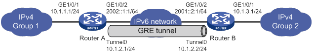
Configuration procedure
Before performing the following configuration, configure an IP address for each interface, and make sure Router A and Router B can reach each other.
1. Configure Router A:
# Create a tunnel interface Tunnel 0, and specify the tunnel mode as GRE/IPv6.
<RouterA> system-view
[RouterA] interface tunnel 0 mode gre ipv6
# Configure an IP address for the tunnel interface.
[RouterA-Tunnel0] ip address 10.1.2.1 255.255.255.0
# Configure the source address of the tunnel interface as the IP address of interface GigabitEthernet 1/0/2 on Router A.
[RouterA-Tunnel0] source 2002::1:1
# Configure the destination address of the tunnel interface as the IP address of interface GigabitEthernet 1/0/2 on Router B.
[RouterA-Tunnel0] destination 2001::2:1
[RouterA-Tunnel0] quit
# Configure a static route from Router A through the tunnel interface to Group 2.
[RouterA] ip route-static 10.1.3.0 255.255.255.0 tunnel 0
2. Configure Router B:
# Create a tunnel interface Tunnel 0, and specify the tunnel mode as GRE/IPv6.
<RouterB> system-view
[RouterB] interface tunnel 0 mode gre ipv6
# Configure an IP address for the tunnel interface.
[RouterB-Tunnel0] ip address 10.1.2.2 255.255.255.0
# Configure the source address of the tunnel interface as the IP address of interface GigabitEthernet 1/0/2 on Router B.
[RouterB-Tunnel0] source 2001::2:1
# Configure the destination address of the tunnel interface as the IP address of interface GigabitEthernet 1/0/2 on Router A.
[RouterB-Tunnel0] destination 2002::1:1
[RouterB-Tunnel0] quit
# Configure a static route from Router B through the tunnel interface to Group 1.
[RouterB] ip route-static 10.1.1.0 255.255.255.0 tunnel 0
Verifying the configuration
# Display tunnel interface information on Router A.
[RouterA] display interface tunnel 0
Tunnel0
Current state: UP
Line protocol state: UP
Description: Tunnel0 Interface
Bandwidth: 64 kbps
Maximum transmission unit: 1456
Internet address: 10.1.2.1/24 (primary)
Tunnel source 2002::1:1, destination 2001::2:1
Tunnel TTL 255
Tunnel protocol/transport GRE/IPv6
GRE key disabled
Checksumming of GRE packets disabled
Output queue - Urgent queuing: Size/Length/Discards 0/100/0
Output queue - Protocol queuing: Size/Length/Discards 0/500/0
Output queue - FIFO queuing: Size/Length/Discards 0/75/0
Last clearing of counters: Never
Last 300 seconds input rate: 0 bytes/sec, 0 bits/sec, 0 packets/sec
Last 300 seconds output rate: 0 bytes/sec, 0 bits/sec, 0 packets/sec
Input: 0 packets, 0 bytes, 0 drops
Output: 0 packets, 0 bytes, 0 drops
# Display tunnel interface information on Router B.
[RouterB] display interface tunnel 0
Tunnel0
Current state: UP
Line protocol state: UP
Description: Tunnel0 Interface
Bandwidth: 64 kbps
Maximum transmission unit: 1456
Internet address: 10.1.2.2/24 (primary)
Tunnel source 2001::2:1, destination 2002::1:1
Tunnel TTL 255
Tunnel protocol/transport GRE/IPv6
GRE key disabled
Checksumming of GRE packets disabled
Output queue - Urgent queuing: Size/Length/Discards 0/100/0
Output queue - Protocol queuing: Size/Length/Discards 0/500/0
Output queue - FIFO queuing: Size/Length/Discards 0/75/0
Last clearing of counters: Never
Last 300 seconds input rate: 0 bytes/sec, 0 bits/sec, 0 packets/sec
Last 300 seconds output rate: 0 bytes/sec, 0 bits/sec, 0 packets/sec
Input: 0 packets, 0 bytes, 0 drops
Output: 0 packets, 0 bytes, 0 drops
# From Router B, ping the IP address of interface GigabitEthernet 1/0/1 on Router A.
[RouterB] ping -a 10.1.3.1 10.1.1.1
Ping 10.1.1.1 (10.1.1.1) from 10.1.3.1: 56 data bytes, press CTRL_C to break
56 bytes from 10.1.1.1: icmp_seq=0 ttl=255 time=2.000 ms
56 bytes from 10.1.1.1: icmp_seq=1 ttl=255 time=1.000 ms
56 bytes from 10.1.1.1: icmp_seq=2 ttl=255 time=1.000 ms
56 bytes from 10.1.1.1: icmp_seq=3 ttl=255 time=0.000 ms
56 bytes from 10.1.1.1: icmp_seq=4 ttl=255 time=1.000 ms
--- Ping statistics for 10.1.1.1 ---
5 packet(s) transmitted, 5 packet(s) received, 0.0% packet loss
round-trip min/avg/max/std-dev = 0.000/1.000/2.000/0.632 ms
The output shows that Router B can successfully ping Router A.
Troubleshooting GRE
The key to configuring GRE is to keep the configuration consistent. Most faults can be located by using the debugging gre or debugging tunnel command. This section analyzes one type of fault for illustration, with the scenario shown in Figure 148.
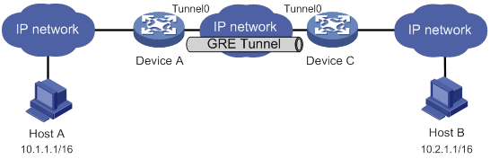
Symptom
The interfaces at both ends of the tunnel are configured correctly and can ping each other, but Host A and Host B cannot ping each other.
Analysis
It might be because that Device A or Device C has no route to reach the peer network.
Solution
1. Execute the display ip routing-table command on Device A and Device C to view whether Device A has a route over tunnel 0 to 10.2.0.0/16 and whether Device C has a route over tunnel 0 to 10.1.0.0/16.
2. If such a route does not exist, execute the ip route-static command in system view to add the route. Take Device A as an example:
[DeviceA] ip route-static 10.2.0.0 255.255.0.0 tunnel 0
Configuring ADVPN
Overview
Auto Discovery Virtual Private Network (ADVPN) enables enterprise branches that use dynamic public addresses to establish a VPN network. ADVPN uses the VPN Address Management (VAM) protocol to collect, maintain, and distribute dynamic public addresses.
VAM uses the client/server model. All VAM clients register their public addresses on the VAM server. A VAM client obtains the public addresses of other clients from the server to establish ADVPN tunnels.
ADVPN structures
ADVPN uses domains to identify VPNs. VAM clients in a VPN must be assigned to the same ADVPN domain. A VAM client can belong to only one ADVPN domain. A VAM server can serve multiple ADVPN domains and manage their clients.
VAM clients include hubs and spokes.
· Hub—A hub is the exchange center of routing information. A hub in a hub-spoke network is also a data forwarding center.
· Spoke—A spoke is the gateway of a branch. It does not forward data received from other ADVPN nodes.
ADVPN supports the following structures:
· Full-mesh—In a full-mesh ADVPN, spokes can directly communicate with each other. The hub acts as the route exchange center.
As shown in Figure 149, the spokes register with the VAM server and get hub information in the ADVPN domain. Then, they establish permanent tunnels to the hub.
Any two spokes can establish a dynamic tunnel to directly exchange data. The tunnel is deleted if no data exists during the idle timeout time.
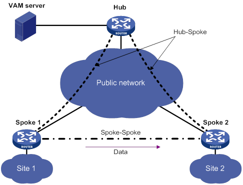
· Hub-spoke—In a hub-spoke ADVPN, spokes communicate with each other through the hub. The hub acts as both the route exchange center and data forwarding center.
As shown in Figure 150, each spoke establishes a permanent tunnel to the hub. Spokes communicate with each other through the hub.
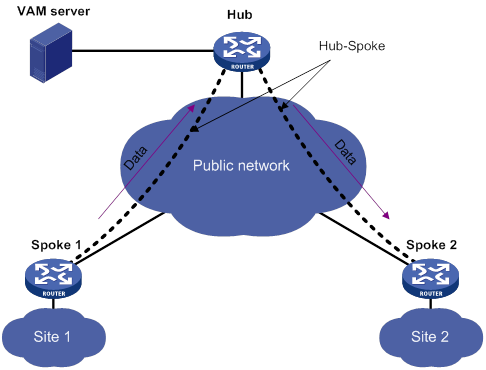
· Hub-group—A hub-group ADVPN can accommodate more ADVPN clients. This allows one hub to manage all clients. As shown in Figure 151, a hub-group ADVPN contains multiple hub groups. Each hub group has one or multiple hubs and spokes.
Follow these guidelines to classify hub groups:
? All hubs must belong to the backbone hub group. This hub group forms the full-mesh backbone area. All hubs obtain information about other hubs from the VAM server and establish permanent ADVPN tunnels to each other.
? Spokes must belong to non-backbone hub groups. Each non-backbone hub group includes at least one hub and uses either the full-mesh or hub-spoke structure. Spokes obtain hub information in the ADVPN domain from the VAM server, and establish permanent tunnels to the hub. Spokes can establish tunnels only to the hubs in the hub group.
Tunnel establishment and data forwarding in a hub group depend on the network structure. Inter-group communications between spokes need to pass the hubs of the groups. To reduce the pressure on hubs during inter-group communications, you can allow spokes in different hub groups to establish a dynamic tunnel. The dynamic tunnel is deleted if no data exists during the idle timeout time.
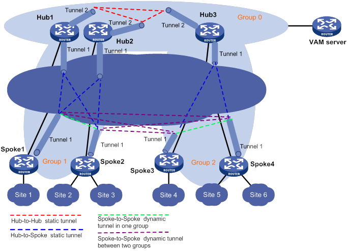
How ADVPN operates
The VAM server must have a static public address. VAM clients have both a public address and a private address. The public address is the address of the interface connected to the public network. It can be manually configured or dynamically assigned. The private address is the address of the ADVPN tunnel interface. It must be manually configured. All the private addresses of clients in an ADVPN domain must belong to the same network segment.
ADVPN includes the following phases:
· Connection initialization.
· Registration.
· Tunnel establishment.
· Route learning and packet forwarding.
Connection initialization
As shown in Figure 152, a client and a server perform the following operations to initialize a connection:
1. The client sends encryption and authentication algorithms to the server in a connection request.
2. The server compares its algorithms in descending order of priority with the algorithms sent by the client.
3. The server sends the matching algorithms to the client.
If no match is found, the negotiation fails.
4. The server and the client generate encryption and authentication keys based on the preshared key.
If authentication and encryption are not needed, they do not generate keys.
5. The server and the client exchange negotiation acknowledgment packets protected by using the keys.
6. The server and the client use the keys to protect subsequent packets if they can restore the protected negotiation acknowledgment packets.
If they cannot restore the packets, the negotiation fails.
Figure 152 Connection initialization process
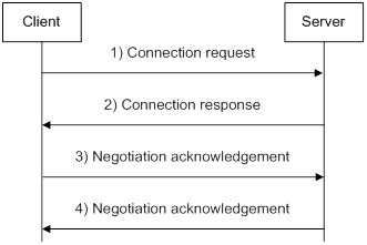
Registration
Figure 153 shows the following registration process:
1. The client sends the server a registration request that includes its public address, private address, and the connected private network.
2. The server sends the client an identity authentication request that specifies the authentication algorithm.
If authentication is not required, the server directly registers the client and sends the client a registration acknowledgement. VAM supports both PAP and CHAP authentication.
3. The client submits its identity information to the server.
4. The server performs authentication and accounting for the client through the AAA server.
5. The server sends the client a registration acknowledgement that includes hub information.
Figure 153 Registration process
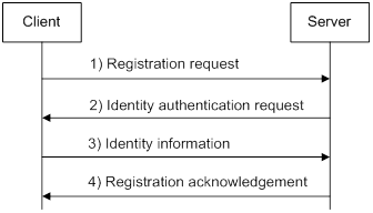
Tunnel establishment
A spoke can establish permanent tunnels to any number of hubs. Hubs in an ADVPN domain must establish permanent tunnels.
Figure 154 shows the tunnel establishment process.
1. The initiator originates a tunnel establishment request.
? To establish a hub-spoke tunnel:
The spoke checks whether a tunnel to each hub exists. If not, the spoke sends a tunnel establishment request to the hub.
? To establish a hub-hub tunnel:
The hub checks whether a tunnel to each peer hub exists. If not, the hub sends a tunnel establishment request to the peer hub.
? To establish a spoke-spoke tunnel:
In a full-mesh network, when a spoke receives a data packet but finds no tunnel for forwarding the packet, it sends an address resolution request to the server. After receiving the resolved address, the spoke sends a tunnel establishment request to the peer spoke.
2. The receiver saves tunnel information in the request and sends a response to the sender.
Figure 154 Tunnel establishment process
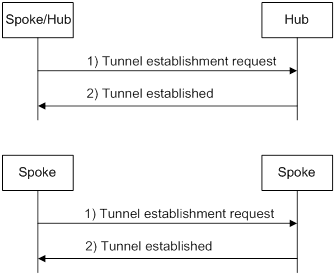
Route learning and packet forwarding
ADVPN nodes use the following methods to learn private routes:
· Static or dynamic routing—It must be configured for private networks and ADVPN tunnel interfaces to ensure connectivity among private networks. A dynamic routing protocol discovers neighbors, updates routes, and establishes a routing table over ADVPN tunnels. From the perspective of private networks, ADVPN tunnels are links that connect different private networks. The routing protocol exchanges routes between hub and hub, and between hub and spoke. It does not directly exchange routes between spoke and spoke.
When a spoke receives a packet destined to a remote private network, it performs the following operations to forward the packet:
a. Locates the private next hop from the routing table.
b. Uses the private next hop to obtain the corresponding public address from the VAM server.
c. Sends the packet to the public address over the ADVPN tunnel.
Full-mesh and hub-spoke structures are determined by routing. If the next hop is a spoke, the structure is full-mesh. If the next hop is a hub, the structure is hub-spoke.
· Registration and query from the VAM server—VAM clients register information about the connected private networks on the VAM server.
When a spoke receives a packet destined to a remote private network, it performs the following operations to forward the packet:
d. Sends the destination address of the packet to the VAM server.
e. Queries the VAM server for information about the ADVPN node (public and private addresses of the node) connected to the remote private network.
f. Generates a route to the remote private network through the ADVPN node.
g. Sends the packet to the public address of the ADVPN node over the ADVPN tunnel.
If both methods are used, the spoke sends both the private next hop and the destination address of the packet to the VAM server. The VAM server preferentially obtains the private network according to the destination address. If the route to the remote private network is learned by using both methods, the route with a lower preference is used.
NAT traversal
An ADVPN tunnel can traverse a NAT gateway.
· If only the tunnel initiator resides behind a NAT gateway, a spoke-spoke tunnel can be established through the NAT gateway.
· If the tunnel receiver resides behind a NAT gateway, packets must be forwarded by a hub before the receiver originates a tunnel establishment request. If the NAT gateway uses Endpoint-Independent Mapping, a spoke-spoke tunnel can be established through the NAT gateway.
· If both ends reside behind a NAT gateway, no tunnel can be established and packets between them must be forwarded by a hub.
QoS for ADVPN tunnel traffic
You can apply a QoS policy to an ADVPN tunnel to control traffic of the ADVPN tunnel.
To apply a QoS policy to an ADVPN tunnel, perform the following tasks:
· Configure an ADVPN group name on the ADVPN tunnel interface of the spoke.
· Configure the mapping between the ADVPN group name and the QoS policy on the hub.
The traffic control procedure is as follows:
1. The spoke carries the configured ADVPN group name in the hub-spoke tunnel request sent to the hub.
2. The hub gets the group name from the received tunnel request, and looks for an ADVPN group-to-QoS policy mapping that matches the group name.
? If a match is found, the hub forwards traffic on the ADVPN tunnel interface according to the matching QoS policy.
? If no match is found, the hub does not apply QoS when forwarding traffic on the ADVPN tunnel interface.
Feature and hardware compatibility
|
Hardware |
ADVPN compatibility |
|
MSR810/810-W/810-W-DB/810-LM/810-W-LM/810-10-PoE/810-LM-HK/810-W-LM-HK/810-LMS/810-LUS |
Yes |
|
MSR2600-6-X1/2600-10-X1 |
Yes |
|
MSR 2630 |
Yes |
|
MSR3600-28/3600-51 |
Yes |
|
MSR3600-28-SI/3600-51-SI |
No |
|
MSR3610-X1/3610-X1-DP/3610-X1-DC/3610-X1-DP-DC |
Yes |
|
MSR 3610/3620/3620-DP/3640/3660 |
Yes |
|
MSR5620/5660/5680 |
Yes |
|
Hardware |
ADVPN compatibility |
|
MSR810-LM-GL |
Yes |
|
MSR810-W-LM-GL |
Yes |
|
MSR830-6EI-GL |
Yes |
|
MSR830-10EI-GL |
Yes |
|
MSR830-6HI-GL |
Yes |
|
MSR830-10HI-GL |
Yes |
|
MSR2600-6-X1-GL |
Yes |
|
MSR3600-28-SI-GL |
No |
ADVPN configuration task list
Configure ADVPN in the order of VAM servers, hubs, and spokes.
Perform the following tasks to configure ADVPN:
|
Tasks at a glance |
|
(Optional.) Configuring AAA |
|
(Required.) Configuring the VAM server |
|
(Required.) Configuring the VAM client |
|
(Required.) Configuring an ADVPN tunnel interface |
|
(Required.) Configuring routing |
|
(Optional.) Configuring IPsec for ADVPN tunnels |
Configuring AAA
The VAM server can use AAA to authenticate clients. Clients passing AAA authentication can access the ADVPN domain. For information about AAA configuration, see Security Configuration Guide.
Configuring the VAM server
Feature and hardware compatibility
The following matrix shows the feature and hardware compatibility:
|
Hardware |
VAM server compatibility |
|
MSR810/810-W/810-W-DB/810-LM/810-W-LM/810-10-PoE/810-LM-HK/810-W-LM-HK/810-LUS |
Yes |
|
MSR810-LMS |
No |
|
MSR2600-6-X1/2600-10-X1 |
Yes |
|
MSR 2630 |
Yes |
|
MSR3600-28/3600-51 |
Yes |
|
MSR3600-28-SI/3600-51-SI |
No |
|
MSR3610-X1/3610-X1-DP/3610-X1-DC/3610-X1-DP-DC |
Yes |
|
MSR 3610/3620/3620-DP/3640/3660 |
Yes |
|
MSR5620/5660/5680 |
Yes |
|
Hardware |
VAM server compatibility |
|
MSR810-LM-GL |
Yes |
|
MSR810-W-LM-GL |
Yes |
|
MSR830-6EI-GL |
Yes |
|
MSR830-10EI-GL |
Yes |
|
MSR830-6HI-GL |
Yes |
|
MSR830-10HI-GL |
Yes |
|
MSR2600-6-X1-GL |
Yes |
|
MSR3600-28-SI-GL |
No |
VAM server configuration task list
|
Tasks at a glance |
|
(Required.) Creating an ADVPN domain |
|
(Required.) Enabling the VAM server |
|
(Required.) Configuring a preshared key for the VAM server |
|
(Required.) Configuring hub groups |
|
(Optional.) Setting the port number of the VAM server |
|
(Optional.) Specifying authentication and encryption algorithms for the VAM server |
|
(Optional.) Configuring an authentication method |
|
(Optional.) Configuring keepalive parameters |
|
(Optional.) Setting the retry timer |
Creating an ADVPN domain
|
Step |
Command |
Remarks |
|
1. Enter system view. |
system-view |
N/A |
|
2. Create an ADVPN domain and enter ADVPN domain view. |
vam server advpn-domain domain-name [ id domain-id ] |
By default, no ADVPN domains exist. Set a unique ID for an ADVPN domain. |
Enabling the VAM server
|
Step |
Command |
Remarks |
|
1. Enter system view. |
system-view |
N/A |
|
2. Enable the VAM server. |
·
Enable the VAM server for one or all
ADVPN domains: · Enable the VAM server for an ADVPN domain: a. vam server advpn-domain domain-name [ id domain-id ] b. server enable |
Use either command. By default, the VAM server is disabled. |
Configuring a preshared key for the VAM server
The preshared key is used to generate initial encryption and authentication keys during connection initialization. It is also used to generate encryption and authentication keys for subsequent packets if encryption and authentication are needed.
The VAM server must have the same preshared key as the clients in the same ADVPN domain. If they have different preshared keys, decryption and authentication will fail, and they cannot establish a connection.
To configure a preshared key for the VAM server:
|
Step |
Command |
Remarks |
|
1. Enter system view. |
system-view |
N/A |
|
2. Enter ADVPN domain view. |
vam server advpn-domain domain-name [ id domain-id ] |
N/A |
|
3. Configure a preshared key for the VAM server. |
pre-shared-key { cipher | simple } string |
By default, no preshared key is configured. |
Configuring hub groups
Hub groups apply to large ADVPN networks. You can classify spokes to different hub groups, and specify one or more hubs for each group.
When a VAM client registers with the VAM server, the VAM server selects a hub group for the client as follows:
1. The server matches the private address of the client against the private addresses of hubs in different hub groups in lexicographic order.
2. If a match is found, the server assigns the client to the hub group as a hub.
3. If no match is found, the server matches the client's private address against the private addresses of spokes in different hub groups in lexicographic order.
4. If a match is found, the server assigns the client to the hub group as a spoke.
5. If no match is found, the registration fails.
The VAM server only assigns hub information in the matching hub group to the client. The client only establishes permanent ADVPN tunnels to the hubs in the matching hub group.
Creating a hub group
|
Step |
Command |
Remarks |
|
1. Enter system view. |
system-view |
N/A |
|
2. Enter ADVPN domain view. |
vam server advpn-domain domain-name [ id domain-id ] |
N/A |
|
3. Create a hub group and enter hub group view. |
hub-group group-name |
By default, no hub group exists. |
Configuring hub private addresses in a hub group
A hub group must have at least one hub private address.
To configure hub private addresses in the hub group:
|
Step |
Command |
Remarks |
|
1. Enter system view. |
system-view |
N/A |
|
2. Enter ADVPN domain view. |
vam server advpn-domain domain-name [ id domain-id ] |
N/A |
|
3. Enter hub group view. |
hub-group group-name |
N/A |
|
4. Configure a hub private address. |
·
Configure a hub private IPv4 address: ·
Configure a hub private IPv6 address: |
Use either command. By default, no hub private address is configured. |
Configuring a spoke private address range in a hub group
You can configure multiple spoke private address ranges in a hub group. The ranges are listed from low to high.
To configure a spoke private address range in a hub group:
|
Step |
Command |
Remarks |
|
1. Enter system view. |
system-view |
N/A |
|
2. Enter ADVPN domain view. |
vam server advpn-domain domain-name [ id domain-id ] |
N/A |
|
3. Enter hub group view. |
hub-group group-name |
N/A |
|
4. Configure a spoke private address range. |
·
Configure a spoke private IPv4 address
range: ·
Configure a spoke private IPv6 address range: |
Use either command. By default, no spoke private address range is configured. |
Specifying an ACL to control establishing spoke-to-spoke tunnels
The VAM server assigns the specified ACL to an online hub. The hub uses the ACL to match received packets. If a match is found, the hub sends a redirect packet to the spoke that sent the packet. Then, the spoke sends the VAM server the destination address of the packet, obtains the remote spoke information, and establishes a direct tunnel to the remote spoke.
To specify an ACL to control establishing spoke-to-spoke tunnels:
|
Step |
Command |
Remarks |
|
1. Enter system view. |
system-view |
N/A |
|
2. Enter ADVPN domain view. |
vam server advpn-domain domain-name [ id domain-id ] |
N/A |
|
3. Enter hub group view. |
hub-group group-name |
N/A |
|
4. Specify an ACL to control establishing spoke-to-spoke tunnels. |
·
Specify an ACL to control establishing
IPv4 spoke-to-spoke tunnels: ·
Specify an ACL to control establishing IPv6
spoke-to-spoke tunnels: |
Use either command. By default, spokes are not allowed to establish direct tunnels. |
Setting the port number of the VAM server
|
Step |
Command |
Remarks |
|
1. Enter system view. |
system-view |
N/A |
|
2. Set the port number of the VAM server. |
vam server listen-port port-number |
The default port number is 18000. The port number of the VAM server must be the same as that configured on the VAM clients. |
Specifying authentication and encryption algorithms for the VAM server
The VAM server uses the specified algorithms to negotiate with the VAM client.
The VAM server and client use SHA-1 and AES-CBC-128 during connection initialization, and use the negotiated algorithms after connection initialization.
The algorithm specified earlier in a command line has a higher priority. The configuration of the commands that specify authentication and encryption algorithms does not affect registered VAM clients. It applies to subsequently registered VAM clients.
To specify authentication and encryption algorithms for the VAM server:
|
Step |
Command |
Remarks |
|
1. Enter system view. |
system-view |
N/A |
|
2. Enter ADVPN domain view. |
vam server advpn-domain domain-name [ id domain-id ] |
N/A |
|
3. Specify authentication algorithms. |
authentication-algorithm { aes-xcbc-mac | md5 | none | sha-1 | sha-256 } * |
The default authentication algorithm is SHA-1. |
|
4. Specify encryption algorithms. |
encryption-algorithm { 3des-cbc | aes-cbc-128 | aes-cbc-192 | aes-cbc-256 | aes-ctr-128 | aes-ctr-192 | aes-ctr-256 | des-cbc | none } * |
The default encryption algorithms are AES-CBC-256, AES-CBC-192, AES-CBC-128, AES-CTR-256, AES-CTR-192, AES-CTR-128, 3DES-CBC, and DES-CBC in descending order of priority. |
Configuring an authentication method
The VAM server uses the specified method to authenticate clients in the ADVPN domain. The VAM server supports PAP and CHAP authentication.
If the specified ISP domain does not exist, the authentication will fail. A newly configured authentication method does not affect registered VAM clients. It applies to subsequently registered VAM clients.
To configure an authentication method:
|
Step |
Command |
Remarks |
|
1. Enter system view. |
system-view |
N/A |
|
2. Enter ADVPN domain view. |
vam server advpn-domain domain-name [ id domain-id ] |
N/A |
|
3. Specify an authentication method. |
authentication-method { none | { chap | pap } [ domain isp-name ] } |
By default, the authentication method is CHAP, and the default domain is used. |
Configuring keepalive parameters
Keepalive parameters include a keepalive interval and a maximum number of keepalive retries. The VAM server assigns the configured keepalive parameters to clients in the ADVPN domain.
A client sends keepalives to the server at the specified interval. If a client does not receive any responses from the server after the maximum keepalive attempts (keepalive retries + 1), the client stops sending keepalives. If the VAM server does not receive any keepalives from a client before the timeout timer expires, the server removes information about the client and logs off the client. The timeout time is the product of the keepalive interval and keepalive attempts.
Newly configured keepalive parameters do not affect registered VAM clients. They apply to subsequently registered clients.
If a device configured with dynamic NAT exists between the VAM server and VAM clients, configure the keepalive interval to be shorter than the aging time of NAT entries.
Configure proper values for the keepalive parameters depending on the network condition.
To configure keepalive parameters:
|
Step |
Command |
Remarks |
|
1. Enter system view. |
system-view |
N/A |
|
2. Enter ADVPN domain view. |
vam server advpn-domain domain-name [ id domain-id ] |
N/A |
|
3. Configure keepalive parameters. |
keepalive interval interval retry retries |
By default, the keepalive interval is 180 seconds, and the maximum number of keepalive retries is 3. |
Setting the retry timer
The VAM server starts the retry timer after it sends a request to a client. If the server does not receive a response from the client before the retry timer expires, the server resends the request. The server stops sending the request after receiving a response from the client or after the timeout timer (product of the keepalive interval and keepalive attempts) expires.
To set the retry timer:
|
Step |
Command |
Remarks |
|
1. Enter system view. |
system-view |
N/A |
|
2. Enter ADVPN domain view. |
vam server advpn-domain domain-name [ id domain-id ] |
N/A |
|
3. Set the retry timer. |
retry interval interval |
By default, the retry timer is 5 seconds. |
Configuring the VAM client
|
Tasks at a glance |
|
(Required.) Creating a VAM client |
|
(Required.) Enabling VAM clients |
|
(Required.) Specifying VAM servers |
|
(Required.) Specifying an ADVPN domain for a VAM client |
|
(Required.) Configuring a preshared key for a VAM client |
|
(Optional.) Setting the retry interval and retry number for a VAM client |
|
(Optional.) Setting the dumb timer for a VAM client |
|
(Optional.) Configuring a username and password for a VAM client |
Creating a VAM client
|
Step |
Command |
Remarks |
|
1. Enter system view. |
system-view |
N/A |
|
2. Create a VAM client and enter its view. |
vam client name client-name |
By default, no client is created. |
Enabling VAM clients
|
Step |
Command |
Remarks |
|
1. Enter system view. |
system-view |
N/A |
|
2. Enable VAM clients. |
·
Enable one or all VAM clients: · Enable a VAM client: a. vam client name client-name b. client enable |
Use either method. By default, no VAM client is enabled. |
Specifying VAM servers
If the specified primary and secondary VAM servers have the same address or name, only the primary VAM server takes effect.
The port number of a VAM server must be the same as that configured on the VAM server.
To specify VAM servers for a client:
|
Step |
Command |
Remarks |
|
|
1. Enter system view. |
system-view |
N/A |
|
|
2. Enter VAM client view. |
vam client name client-name |
N/A |
|
|
3. Specify the primary VAM server. |
server primary { ip-address ip-address | ipv6-address ipv6-address | name host-name } [ port port-number ] |
By default, no VAM server is specified. |
|
|
4. (Optional.) Specify the secondary VAM server. |
server secondary { ip-address ip-address | ipv6-address ipv6-address | name host-name } [ port port-number ] |
By default, no VAM server is specified. |
|
Specifying an ADVPN domain for a VAM client
|
Step |
Command |
Remarks |
|
1. Enter system view. |
system-view |
N/A |
|
2. Enter VAM client view. |
vam client name client-name |
N/A |
|
3. Specify an ADVPN domain for the VAM client. |
advpn-domain domain-name |
By default, no ADVPN domain is specified for a VAM client. |
Configuring a preshared key for a VAM client
The preshared key is used to generate initial encryption and authentication keys during connection initialization. It is also used to generate encryption and authentication keys for subsequent packets if encryption and authentication are needed.
All VAM clients and the VAM server in an ADVPN domain must have the same preshared key. If they have different preshared keys, the decryption and authentication will fail, and they cannot establish any connection.
To configure a preshared key for a VAM client:
|
Step |
Command |
Remarks |
|
1. Enter system view. |
system-view |
N/A |
|
2. Enter VAM client view. |
vam client name client-name |
N/A |
|
3. Configure a preshared key for the VAM client. |
pre-shared-key { cipher | simple } string |
By default, no preshared key is configured for a VAM client. |
Setting the retry interval and retry number for a VAM client
After a VAM client sends a request to the server, it resends the request if it does not receive any responses within the retry interval. If the client fails to receive a response after maximum attempts (retry times + 1), the client determines that the server is unreachable.
The retry-times setting does not apply to register and update requests. The client sends those requests at the retry interval until it goes offline.
To set the retry interval and retry number for a VAM client:
|
Step |
Command |
Remarks |
|
1. Enter system view. |
system-view |
N/A |
|
2. Enter VAM client view. |
vam client name client-name |
N/A |
|
3. Set the retry interval and retry number. |
retry interval interval count retries |
By default, the retry interval is 5 seconds, and the retry number are 3. |
Setting the dumb timer for a VAM client
A VAM client starts the dumb timer after the timeout timer expires. The client does not process any packets during the dumb time. When the dumb timer expires, the client sends a new connection request to the VAM server.
To set the dumb timer for a VAM client:
|
Step |
Command |
Remarks |
|
1. Enter system view. |
system-view |
N/A |
|
2. Enter VAM client view. |
vam client name client-name |
N/A |
|
3. Set the dumb timer. |
dumb-time time-interval |
By default, the dumb timer is 120 seconds. |
Configuring a username and password for a VAM client
The VAM client uses the configured username and password for authentication on the server.
To configure a username and password for a VAM client:
|
Step |
Command |
Remarks |
|
1. Enter system view. |
system-view |
N/A |
|
2. Enter VAM client view. |
vam client name client-name |
N/A |
|
3. Configure a username and password for the client. |
user username password { cipher | simple } string |
By default, no username and password is configured for the client. |
Configuring an ADVPN tunnel interface
ADVPN establishes tunnels over ADVPN tunnel interfaces.
To configure an ADVPN tunnel interface:
|
Step |
Command |
Remarks |
|
1. Enter system view. |
system-view |
N/A |
|
2. Create an ADVPN tunnel interface and enter its view. |
interface tunnel number [ mode advpn { gre | udp } [ ipv6 ] ] |
By default, no tunnel interfaces exist. The two ends of an ADVPN tunnel must use the same tunnel mode. |
|
3. Configure a private IPv4 or IPv6 address for the tunnel interface. |
·
Configure a private IPv4 address: ·
Configure a private IPv6 address: |
By default, no private address is configured for the tunnel interface. All tunnel interfaces in a hub group must reside in the same private network. |
|
4. Specify a source address or source interface for the tunnel interface. |
source { ip-address | interface-type interface-number } |
By default, no source address or source interface is configured for a tunnel interface. The specified source address or the IP address of the specified source interface is used as the source address of sent ADVPN packets. If multiple GRE ADVPN tunnel interfaces have the same source address or source interface, you must configure different GRE keys for the interfaces. For information about GRE keys, see Layer 3—IP Services Configuration Guide. |
|
5. (Optional.) Set the DF bit for ADVPN packets. |
tunnel dfbit enable |
By default, the DF bit is not set for ADVPN packets. |
|
6. (Optional.) Set the source UDP port number of ADVPN packets. |
advpn source-port port-number |
By default, the source UDP port number of ADVPN packets is 18001. This command is available when the tunnel mode is UDP. If the vam client command configured on the tunnel interface has the compatible keyword, the tunnel interface must have a different source UDP port number than other tunnel interfaces. |
|
7. Bind a VAM client to the tunnel interface. |
·
Bind an IPv4 VAM client to the tunnel
interface: ·
Bind an IPv6 VAM client to the tunnel
interface: |
By default, no VAM client is bound to an ADVPN tunnel interface. A VAM client can be bound to only one IPv4 or IPv6 ADVPN tunnel interface. |
|
8. (Optional.) Configure a private network for the tunnel interface. |
·
Configure a private IPv4 network for the
tunnel interface: ·
Configure a private IPv6 network for the
tunnel interface: |
By default, no private network is configured for the tunnel interface. Set the preference of the private network route to be higher than other dynamic routing protocols, and lower than static routing. |
|
9. (Optional.) Set the keepalive interval and the maximum number of keepalive attempts for the tunnel interface. |
keepalive interval interval retry retries |
By default, the keepalive interval is 180 seconds, and the maximum number of keepalive attempts is 3. The keepalive interval and the maximum number of keepalive attempts must be the same on the tunnel interfaces in an ADVPN domain. |
|
10. (Optional.) Set the idle timeout time for the spoke-spoke tunnel. |
advpn session idle-time time-interval |
By default, the idle timeout time is 600 seconds. The new idle timeout setting applies to both existing and subsequently established spoke-spoke tunnels. |
|
11. (Optional.) Set the dumb time for the tunnel interface. |
advpn session dumb-time time-interval |
By default, the dumb time is 120 seconds. The new dumb time setting only applies to subsequently established tunnels. |
|
12. (Optional.) Configure an ADVPN group name. |
advpn group group-name |
By default, no ADVPN group name is configured. Perform this task on the spoke. |
|
13. (Optional.) Configure a mapping between an ADVPN group and a QoS policy. |
advpn map group group-name qos-policy policy-name outbound |
By default, no ADVPN group-to-QoS policy mappings are configured. Perform this task on the hub. |
For more information about tunnel interface configurations and commands, see Layer 3—IP Services Configuration Guide and Layer 3—IP Services Command Reference.
Configuring routing
ADVPN supports OSPF and BGP for IPv4:
· When OSPF is used, set the network type of an OSPF interface to broadcast in a full-mesh network or to P2MP in a hub-spoke network.
· When BGP is used, configure a routing policy to make sure the next hop of a route destined for a remote private network is the IP address of the peer spoke in a full-mesh network (EBGP does not support full-mesh), or is the IP address of the hub in a hub-spoke network.
ADVPN supports OSPFv3 and IPv6 BGP for IPv6:
· When OSPFv3 is used, set the network type of an OSPFv3 interface to broadcast in a full-mesh network or to P2MP in a hub-spoke network.
· When IPv6 BGP is used, configure a routing policy to make sure the next hop of a route destined for a remote private network is the IP address of the peer spoke in a full-mesh network (EBGP does not support full-mesh), or is the IP address of the hub in a hub-spoke network.
For more information about routing protocols and policies, see Layer 3—IP Routing Configuration Guide.
Configuring IPsec for ADVPN tunnels
You can configure an IPsec profile to secure ADVPN tunnels:
1. Configure IPsec transform sets to specify the security protocols, authentication and encryption algorithms, and the encapsulation mode.
2. Configure an IKE-mode IPsec profile that uses the IPsec transform sets.
3. Apply the IPsec profile to an ADVPN tunnel interface.
For more information about IPsec configuration, see Security Configuration Guide.
Displaying and maintaining ADVPN
Execute display commands in any view and reset commands in user view.
|
Task |
Command |
|
Display IPv4 private-to-public address mapping information for VAM clients registered with the VAM server. |
display vam server address-map [ advpn-domain domain-name [ private-address private-ip-address ] ] [ verbose ] |
|
Display IPv6 private-to-public address mapping information for VAM clients registered with the VAM server. |
display vam server ipv6 address-map [ advpn-domain domain-name [ private-address private-ipv6-address ] ] [ verbose ] |
|
Display IPv4 private networks for VAM clients registered with the VAM server. |
display vam server private-network [ advpn-domain domain-name [ private-address private-ip-address ] ] |
|
Display IPv6 private networks for VAM clients registered with the VAM server. |
display vam server ipv6 private-network [ advpn-domain domain-name [ private-address private-ipv6-address ] ] |
|
Display ADVPN domain statistics on the VAM server. |
display vam server statistics [ advpn-domain domain-name ] |
|
Display FSM information for VAM clients. |
display vam client fsm [ name client-name ] |
|
Display statistics for VAM clients. |
display vam client statistics [ name client-name ] |
|
Display IPv4 spoke-to-spoke tunnel establishment rules for VAM clients. |
display vam client shortcut interest [ name client-name ] |
|
Display IPv6 spoke-to-spoke tunnel establishment rules for VAM clients. |
display vam client shortcut ipv6 interest [ name client-name ] |
|
Display ADVPN group-to-QoS policy mappings. |
display advpn group-qos-map [ interface tunnel number [ group group-name ] ] |
|
Display IPv4 ADVPN tunnel information. |
display advpn session [ interface tunnel number [ private-address private-ip-address ] ] [ verbose ] |
|
Display IPv6 ADVPN tunnel information. |
display advpn ipv6 session [ interface tunnel number [ private-address private-ipv6-address ] ] [ verbose ] |
|
Display the number of ADVPN sessions in different states. |
display advpn session count |
|
Clear IPv4 private-to-public address mapping information for VAM clients registered with the VAM server. |
reset vam server address-map [ advpn-domain domain-name [ private-address private-ip-address ] ] |
|
Clear IPv6 private-to-public address mapping information for VAM clients registered with the VAM server. |
reset vam server ipv6 address-map [ advpn-domain domain-name [ private-address private-ipv6-address ] ] |
|
Clear ADVPN domain statistics on the VAM server. |
reset vam server statistics [ advpn-domain domain-name ] |
|
Reset the FSM for VAM clients. |
reset vam client [ ipv6 ] fsm [ name client-name ] |
|
Clear statistics for VAM client. |
reset vam client statistics [ name client-name ] |
|
Delete IPv4 ADVPN tunnels. |
reset advpn session statistics [ interface tunnel number [ private-address private-ip-address ] ] |
|
Delete IPv6 ADVPN tunnels. |
reset advpn ipv6 session statistics [ interface tunnel number [ private-address private-ipv6-address ] ] |
|
Clear statistics for IPv4 ADVPN tunnels. |
reset advpn session statistics [ interface tunnel number [ private-address private-ip-address ] ] |
|
Clear statistics for IPv6 ADVPN tunnels. |
reset advpn ipv6 session statistics [ interface tunnel number [ private-address private-ipv6-address ] ] |
ADVPN configuration examples
IPv4 full-mesh ADVPN configuration example
Network requirements
As shown in Figure 155, the primary and secondary VAM servers manage and maintain VAM client information for all hubs and spokes. The AAA server performs authentication and accounting for VAM clients. The two hubs back up each other, and perform data forwarding and route exchange.
· Establish a permanent ADVPN tunnel between each spoke and each hub.
· Establish a temporary ADVPN tunnel dynamically between the two spokes in the same ADVPN domain.

Table 12 Interface and IP address assignment
|
Device |
Interface |
IP address |
Device |
Interface |
IP address |
|
Hub 1 |
GE2/0/1 |
1.0.0.1/24 |
Spoke 1 |
GE2/0/1 |
1.0.0.3/24 |
|
|
Tunnel1 |
192.168.0.1/24 |
|
GE2/0/2 |
192.168.1.1/24 |
|
Hub 2 |
GE2/0/1 |
1.0.0.2/24 |
|
Tunnel1 |
192.168.0.3/24 |
|
|
Tunnel1 |
192.168.0.2/24 |
Spoke 2 |
GE2/0/1 |
1.0.0.4/24 |
|
AAA server |
|
1.0.0.10/24 |
|
GE2/0/2 |
192.168.2.1/24 |
|
Primary server |
GE2/0/1 |
1.0.0.11/24 |
|
Tunnel1 |
192.168.0.4/24 |
|
Secondary server |
GE2/0/1 |
1.0.0.12/24 |
|
|
|
Configuring the primary VAM server
1. Configure IP addresses for the interfaces. (Details not shown.)
2. Configure AAA:
# Configure RADIUS scheme abc.
<PrimaryServer> system-view
[PrimaryServer] radius scheme abc
[PrimaryServer-radius-abc] primary authentication 1.0.0.10 1812
[PrimaryServer-radius-abc] primary accounting 1.0.0.10 1813
[PrimaryServer-radius-abc] key authentication simple 123
[PrimaryServer-radius-abc] key accounting simple 123
[PrimaryServer-radius-abc] user-name-format without-domain
[PrimaryServer-radius-abc] quit
[PrimaryServer] radius session-control enable
# Configure AAA methods for ISP domain abc.
[PrimaryServer] domain abc
[PrimaryServer-isp-abc] authentication advpn radius-scheme abc
[PrimaryServer-isp-abc] accounting advpn radius-scheme abc
[PrimaryServer-isp-abc] quit
[PrimaryServer] domain default enable abc
3. Configure the VAM server:
# Create ADVPN domain abc.
[PrimaryServer] vam server advpn-domain abc id 1
# Create hub group 0.
[PrimaryServer-vam-server-domain-abc] hub-group 0
# Specify hub private IPv4 addresses.
[PrimaryServer-vam-server-domain-abc-hub-group-0] hub private-address 192.168.0.1
[PrimaryServer-vam-server-domain-abc-hub-group-0] hub private-address 192.168.0.2
# Specify a spoke private IPv4 network.
[PrimaryServer-vam-server-domain-abc-hub-group-0] spoke private-address network 192.168.0.0 255.255.255.0
[PrimaryServer-vam-server-domain-abc-hub-group-0] quit
# Set the preshared key to 123456.
[PrimaryServer-vam-server-domain-abc] pre-shared-key simple 123456
# Set the authentication mode to CHAP.
[PrimaryServer-vam-server-domain-abc] authentication-method chap
# Enable the VAM server for the ADVPN domain.
[PrimaryServer-vam-server-domain-abc] server enable
[PrimaryServer-vam-server-domain-abc] quit
Configuring the secondary VAM server
# Configure the secondary VAM server in the same way that the primary server is configured. (Details not shown.)
Configuring Hub 1
1. Configure IP addresses for the interfaces. (Details not shown.)
2. Configure the VAM client:
# Create VAM client Hub1.
<Hub1> system-view
[Hub1] vam client name Hub1
# Specify ADVPN domain abc for the VAM client.
[Hub1-vam-client-Hub1] advpn-domain abc
# Set the preshared key to 123456.
[Hub1-vam-client-Hub1] pre-shared-key simple 123456
# Set both the username and password to hub1.
[Hub1-vam-client-Hub1] user hub1 password simple hub1
# Specify the primary and secondary VAM servers.
[Hub1-vam-client-Hub1] server primary ip-address 1.0.0.11
[Hub1-vam-client-Hub1] server secondary ip-address 1.0.0.12
# Enable the VAM client.
[Hub1-vam-client-Hub1] client enable
[Hub1-vam-client-Hub1] quit
3. Configure an IPsec profile:
# Configure IKE.
[Hub1] ike keychain abc
[Hub1-ike-keychain-abc] pre-shared-key address 0.0.0.0 0.0.0.0 key simple 123456
[Hub1-ike-keychain-abc] quit
[Hub1] ike profile abc
[Hub1-ike-profile-abc] keychain abc
[Hub1-ike-profile-abc] quit
# Configure the IPsec profile.
[Hub1] ipsec transform-set abc
[Hub1-ipsec-transform-set-abc] encapsulation-mode transport
[Hub1-ipsec-transform-set-abc] esp encryption-algorithm des-cbc
[Hub1-ipsec-transform-set-abc] esp authentication-algorithm sha1
[Hub1-ipsec-transform-set-abc] quit
[Hub1] ipsec profile abc isakmp
[Hub1-ipsec-profile-isakmp-abc] transform-set abc
[Hub1-ipsec-profile-isakmp-abc] ike-profile abc
[Hub1-ipsec-profile-isakmp-abc] quit
4. Configure OSPF to advertise the private network.
[Hub1] ospf 1
[Hub1-ospf-1] area 0
[Hub1-ospf-1-area-0.0.0.0] network 192.168.0.0 0.0.0.255
[Hub1-ospf-1-area-0.0.0.0] quit
[Hub1-ospf-1] quit
5. Configure GRE-mode IPv4 ADVPN tunnel interface tunnel1.
[Hub1] interface tunnel1 mode advpn gre
[Hub1-Tunnel1] ip address 192.168.0.1 255.255.255.0
[Hub1-Tunnel1] vam client Hub1
[Hub1-Tunnel1] ospf network-type broadcast
[Hub1-Tunnel1] source gigabitethernet 2/0/1
[Hub1-Tunnel1] tunnel protection ipsec profile abc
[Hub1-Tunnel1] quit
Configuring Hub 2
1. Configure IP addresses for the interfaces. (Details not shown.)
2. Configure the VAM client:
# Create VAM client Hub2.
<Hub2> system-view
[Hub2] vam client name Hub2
# Specify ADVPN domain abc for the VAM client.
[Hub2-vam-client-Hub2] advpn-domain abc
# Set the preshared key to 123456.
[Hub2-vam-client-Hub2] pre-shared-key simple 123456
# Set both the username and password to hub2.
[Hub2-vam-client-Hub2] user hub2 password simple hub2
# Specify the primary and secondary VAM servers.
[Hub2-vam-client-Hub2] server primary ip-address 1.0.0.11
[Hub2-vam-client-Hub2] server secondary ip-address 1.0.0.12
# Enable the VAM client.
[Hub2-vam-client-Hub2] client enable
[Hub2-vam-client-Hub2] quit
3. Configure an IPsec profile:
# Configure IKE.
[Hub2] ike keychain abc
[Hub2-ike-keychain-abc] pre-shared-key address 0.0.0.0 0.0.0.0 key simple 123456
[Hub2-ike-keychain-abc] quit
[Hub2] ike profile abc
[Hub2-ike-profile-abc] keychain abc
[Hub2-ike-profile-abc] quit
# Configure the IPsec profile.
[Hub2] ipsec transform-set abc
[Hub2-ipsec-transform-set-abc] encapsulation-mode transport
[Hub2-ipsec-transform-set-abc] esp encryption-algorithm des-cbc
[Hub2-ipsec-transform-set-abc] esp authentication-algorithm sha1
[Hub2-ipsec-transform-set-abc] quit
[Hub2] ipsec profile abc isakmp
[Hub2-ipsec-profile-isakmp-abc] transform-set abc
[Hub2-ipsec-profile-isakmp-abc] ike-profile abc
[Hub2-ipsec-profile-isakmp-abc] quit
4. Configure OSPF to advertise the private network.
[Hub2] ospf 1
[Hub2-ospf-1] area 0
[Hub2-ospf-1-area-0.0.0.0] network 192.168.0.0 0.0.0.255
[Hub2-ospf-1-area-0.0.0.0] quit
[Hub2-ospf-1] quit
5. Configure GRE-mode IPv4 ADVPN tunnel interface tunnel1.
[Hub2] interface tunnel 1 mode advpn gre
[Hub2-Tunnel1] ip address 192.168.0.2 255.255.255.0
[Hub2-Tunnel1] vam client Hub2
[Hub2-Tunnel1] ospf network-type broadcast
[Hub2-Tunnel1] source gigabitethernet 2/0/1
[Hub2-Tunnel1] tunnel protection ipsec profile abc
[Hub2-Tunnel1] quit
Configuring Spoke 1
1. Configure IP addresses for the interfaces. (Details not shown.)
2. Configure the VAM client:
# Create VAM client Spoke1.
<Spoke1> system-view
[Spoke1] vam client name Spoke1
# Specify ADVPN domain abc for the VAM client.
[Spoke1-vam-client-Spoke1] advpn-domain abc
# Set the preshared key to 123456.
[Spoke1-vam-client-Spoke1] pre-shared-key simple 123456
# Set both the username and password to spoke1.
[Spoke1-vam-client-Spoke1] user spoke1 password simple spoke1
# Specify the primary and secondary VAM servers.
[Spoke1-vam-client-Spoke1] server primary ip-address 1.0.0.11
[Spoke1-vam-client-Spoke1] server secondary ip-address 1.0.0.12
# Enable the VAM client.
[Spoke1-vam-client-Spoke1] client enable
[Spoke1-vam-client-Spoke1] quit
3. Configure an IPsec profile:
# Configure IKE.
[Spoke1] ike keychain abc
[Spoke1-ike-keychain-abc] pre-shared-key address 0.0.0.0 0.0.0.0 key simple 123456
[Spoke1-ike-keychain-abc] quit
[Spoke1] ike profile abc
[Spoke1-ike-profile-abc] keychain abc
[Spoke1-ike-profile-abc] quit
# Configure the IPsec profile.
[Spoke1] ipsec transform-set abc
[Spoke1-ipsec-transform-set-abc] encapsulation-mode transport
[Spoke1-ipsec-transform-set-abc] esp encryption-algorithm des-cbc
[Spoke1-ipsec-transform-set-abc] esp authentication-algorithm sha1
[Spoke1-ipsec-transform-set-abc] quit
[Spoke1] ipsec profile abc isakmp
[Spoke1-ipsec-profile-isakmp-abc] transform-set abc
[Spoke1-ipsec-profile-isakmp-abc] ike-profile abc
[Spoke1-ipsec-profile-isakmp-abc] quit
4. Configure OSPF to advertise private networks.
[Spoke1] ospf 1
[Spoke1-ospf-1] area 0
[Spoke1-ospf-1-area-0.0.0.0] network 192.168.0.0 0.0.0.255
[Spoke1-ospf-1-area-0.0.0.0] network 192.168.1.0 0.0.0.255
[Spoke1-ospf-1-area-0.0.0.0] quit
[Spoke1-ospf-1] quit
5. Configure GRE-mode IPv4 ADVPN tunnel interface tunnel1. Configure its DR priority as 0 so Spoke 1 will not participate in DR/BDR election.
[Spoke1] interface tunnel1 mode advpn gre
[Spoke1-Tunnel1] ip address 192.168.0.3 255.255.255.0
[Spoke1-Tunnel1] vam client Spoke1
[Spoke1-Tunnel1] ospf network-type broadcast
[Spoke1-Tunnel1] ospf dr-priority 0
[Spoke1-Tunnel1] source gigabitethernet 2/0/1
[Spoke1-Tunnel1] tunnel protection ipsec profile abc
[Spoke1-Tunnel1] quit
Configuring Spoke 2
1. Configure IP addresses for the interfaces. (Details not shown.)
2. Configure the VAM client:
# Create VAM client Spoke2.
<Spoke2> system-view
[Spoke2] vam client name Spoke2
# Specify ADVPN domain abc for the VAM client.
[Spoke2-vam-client-Spoke2] advpn-domain abc
# Set the preshared key to 123456.
[Spoke2-vam-client-Spoke2] pre-shared-key simple 123456
# Set both the username and password to spoke2.
[Spoke2-vam-client-Spoke2] user spoke2 password simple spoke2
# Specify the primary and secondary VAM servers.
[Spoke2-vam-client-Spoke2] server primary ip-address 1.0.0.11
[Spoke2-vam-client-Spoke2] server secondary ip-address 1.0.0.12
# Enable the VAM client.
[Spoke2-vam-client-Spoke2] client enable
[Spoke2-vam-client-Spoke2] quit
3. Configure an IPsec profile:
# Configure IKE.
[Spoke2] ike keychain abc
[Spoke2-ike-keychain-abc] pre-shared-key address 0.0.0.0 0.0.0.0 key simple 123456
[Spoke2-ike-keychain-abc] quit
[Spoke2] ike profile abc
[Spoke2-ike-profile-abc] keychain abc
[Spoke2-ike-profile-abc] quit
# Configure the IPsec profile.
[Spoke2] ipsec transform-set abc
[Spoke2-ipsec-transform-set-abc] encapsulation-mode transport
[Spoke2-ipsec-transform-set-abc] esp encryption-algorithm des-cbc
[Spoke2-ipsec-transform-set-abc] esp authentication-algorithm sha1
[Spoke2-ipsec-transform-set-abc] quit
[Spoke2] ipsec profile abc isakmp
[Spoke2-ipsec-profile-isakmp-abc] transform-set abc
[Spoke2-ipsec-profile-isakmp-abc] ike-profile abc
[Spoke2-ipsec-profile-isakmp-abc] quit
4. Configure OSPF to advertise private networks.
[Spoke2] ospf 1
[Spoke2-ospf-1] area 0
[Spoke2-ospf-1-area-0.0.0.0] network 192.168.0.0 0.0.0.255
[Spoke2-ospf-1-area-0.0.0.0] network 192.168.2.0 0.0.0.255
[Spoke2-ospf-1-area-0.0.0.0] quit
[Spoke2-ospf-1] quit
5. Configure GRE-mode IPv4 ADVPN tunnel interface tunnel1. Configure its DR priority as 0 so Spoke 2 will not participate in DR/BDR election.
[Spoke2] interface tunnel1 mode advpn gre
[Spoke2-Tunnel1] ip address 192.168.0.4 255.255.255.0
[Spoke2-Tunnel1] vam client Spoke2
[Spoke2-Tunnel1] ospf network-type broadcast
[Spoke2-Tunnel1] ospf dr-priority 0
[Spoke2-Tunnel1] source gigabitethernet 2/0/1
[Spoke2-Tunnel1] tunnel protection ipsec profile abc
[Spoke2-Tunnel1] quit
Verifying the configuration
# Display IPv4 address mapping information for all VAM clients registered with the primary VAM server.
[PrimaryServer] display vam server address-map
ADVPN domain name: abc
Total private address mappings: 4
Group Private address Public address Type NAT Holding time
0 192.168.0.1 1.0.0.1 Hub No 0H 52M 7S
0 192.168.0.2 1.0.0.2 Hub No 0H 47M 31S
0 192.168.0.3 1.0.0.3 Spoke No 0H 28M 25S
0 192.168.0.4 1.0.0.4 Spoke No 0H 19M 15S
# Display IPv4 address mapping information for all VAM clients registered with the secondary VAM server.
[SecondaryServer] display vam server address-map
ADVPN domain name: abc
Total private address mappings: 4
Group Private address Public address Type NAT Holding time
0 192.168.0.1 1.0.0.1 Hub No 0H 52M 7S
0 192.168.0.2 1.0.0.2 Hub No 0H 47M 31S
0 192.168.0.3 1.0.0.3 Spoke No 0H 28M 25S
0 192.168.0.4 1.0.0.4 Spoke No 0H 19M 15S
The output shows that Hub 1, Hub 2, Spoke 1, and Spoke 2 all have registered their address mapping information with the VAM servers.
# Display IPv4 ADVPN tunnel information on Hubs. This example uses Hub 1.
[Hub1] display advpn session
Interface : Tunnel1
Number of sessions: 3
Private address Public address Port Type State Holding time
192.168.0.2 1.0.0.2 -- H-H Success 0H 46M 8S
192.168.0.3 1.0.0.3 -- H-S Success 0H 27M 27S
192.168.0.4 1.0.0.4 -- H-S Success 0H 18M 18S
The output shows that Hub 1 has established a permanent tunnel to Hub 2, Spoke 1, and Spoke 2.
# Display IPv4 ADVPN tunnel information on Spokes. This example uses Spoke 1.
[Spoke1] display advpn session
Interface : Tunnel1
Number of sessions: 2
Private address Public address Port Type State Holding time
192.168.0.1 1.0.0.1 -- S-H Success 0H 46M 8S
192.168.0.2 1.0.0.2 -- S-H Success 0H 46M 8S
The output shows that Spoke 1 has established a permanent hub-spoke tunnel to Hub 1 and Hub 2.
# Verify that Spoke 1 can ping the private address 192.168.0.4 of Spoke 2.
[Spoke1] ping 192.168.0.4
Ping 192.168.0.4 (192.168.0.4): 56 data bytes, press CTRL_C to break
56 bytes from 192.168.0.4: icmp_seq=0 ttl=255 time=4.000 ms
56 bytes from 192.168.0.4: icmp_seq=1 ttl=255 time=0.000 ms
56 bytes from 192.168.0.4: icmp_seq=2 ttl=255 time=0.000 ms
56 bytes from 192.168.0.4: icmp_seq=3 ttl=255 time=0.000 ms
56 bytes from 192.168.0.4: icmp_seq=4 ttl=255 time=1.000 ms
--- Ping statistics for 192.168.0.4 ---
5 packets transmitted, 5 packets received, 0.0% packet loss
round-trip min/avg/max/std-dev = 0.000/1.000/4.000/1.549 ms
# Display IPv4 ADVPN tunnel information on Spokes. This example uses Spoke 1.
[Spoke1] display advpn session
Interface : Tunnel1
Number of sessions: 3
Private address Public address Port Type State Holding time
192.168.0.1 1.0.0.1 -- S-H Success 0H 46M 8S
192.168.0.2 1.0.0.2 -- S-H Success 0H 46M 8S
192.168.0.4 1.0.0.4 -- S-S Success 0H 0M 1S
The output shows the following information:
· Spoke 1 has established a permanent hub-spoke tunnel to Hub 1 and Hub 2.
· Spoke 1 has established a temporary spoke-spoke tunnel to Spoke 2.
IPv6 full-mesh ADVPN configuration example
Network requirements
As shown in Figure 156, the primary and secondary VAM servers manage and maintain VAM client information for all hubs and spokes. The AAA server performs authentication and accounting for VAM clients. The two hubs back up each other, and perform data forwarding and route exchange.
· Establish a permanent ADVPN tunnel between each spoke and each hub.
· Establish a temporary ADVPN tunnel dynamically between the two spokes in the same ADVPN domain.
Table 13 Interface and IP address assignment
|
Device |
Interface |
IP address |
Device |
Interface |
IP address |
|
Hub 1 |
GE2/0/1 |
1::1/64 |
Spoke 1 |
GE2/0/1 |
1::3/64 |
|
|
Tunnel1 |
192:168::1/64 |
|
GE2/0/2 |
192:168:1::1/64 |
|
Hub 2 |
GE2/0/1 |
1::2/64 |
|
Tunnel1 |
192:168::3/64 |
|
|
Tunnel1 |
192:168::2/64 |
Spoke 2 |
GE2/0/1 |
1::4/64 |
|
AAA server |
|
1::10/64 |
|
GE2/0/2 |
192:168:2::1/64 |
|
Primary server |
GE2/0/1 |
1::11/64 |
|
Tunnel1 |
192:168::4/64 |
|
Secondary server |
GE2/0/1 |
1::12/64 |
|
|
|
Configuring the primary VAM server
1. Configure IP addresses for the interfaces. (Details not shown.)
2. Configure AAA:
# Configure RADIUS scheme abc.
<PrimaryServer> system-view
[PrimaryServer] radius scheme abc
[PrimaryServer-radius-abc] primary authentication ipv6 1::10 1812
[PrimaryServer-radius-abc] primary accounting ipv6 1::10 1813
[PrimaryServer-radius-abc] key authentication simple 123
[PrimaryServer-radius-abc] key accounting simple 123
[PrimaryServer-radius-abc] user-name-format without-domain
[PrimaryServer-radius-abc] quit
[PrimaryServer] radius session-control enable
# Configure AAA methods for ISP domain abc.
[PrimaryServer] domain abc
[PrimaryServer-isp-abc] authentication advpn radius-scheme abc
[PrimaryServer-isp-abc] accounting advpn radius-scheme abc
[PrimaryServer-isp-abc] quit
[PrimaryServer] domain default enable abc
3. Configure the VAM server:
# Create ADVPN domain abc.
[PrimaryServer] vam server advpn-domain abc id 1
# Create hub group 0.
[PrimaryServer-vam-server-domain-abc] hub-group 0
# Specify hub private IPv6 addresses.
[PrimaryServer-vam-server-domain-abc-hub-group-0] hub ipv6 private-address 192:168::1
[PrimaryServer-vam-server-domain-abc-hub-group-0] hub ipv6 private-address 192:168::2
# Specify a spoke private IPv6 network.
[PrimaryServer-vam-server-domain-abc-hub-group-0] spoke ipv6 private-address network 192:168::0 64
# Set the preshared key to 123456.
[PrimaryServer-vam-server-domain-abc] pre-shared-key simple 123456
# Set the authentication mode to CHAP.
[PrimaryServer-vam-server-domain-abc] authentication-method chap
# Enable the VAM server for the ADVPN domain.
[PrimaryServer-vam-server-domain-abc] server enable
[PrimaryServer-vam-server-domain-abc] quit
Configuring the secondary VAM server
# Configure the secondary VAM server in the same way that the primary server is configured. (Details not shown.)
Configuring Hub 1
1. Configure IP addresses for the interfaces. (Details not shown.)
2. Configure the VAM client:
# Create VAM client Hub1.
<Hub1> system-view
[Hub1] vam client name Hub1
# Specify ADVPN domain abc for the VAM client.
[Hub1-vam-client-Hub1] advpn-domain abc
# Set the preshared key to 123456.
[Hub1-vam-client-Hub1] pre-shared-key simple 123456
# Set both the username and password to hub1.
[Hub1-vam-client-Hub1] user hub1 password simple hub1
# Specify the primary and secondary VAM servers.
[Hub1-vam-client-Hub1] server primary ipv6-address 1::11
[Hub1-vam-client-Hub1] server secondary ipv6-address 1::12
# Enable the VAM client.
[Hub1-vam-client-Hub1] client enable
[Hub1-vam-client-Hub1] quit
3. Configure an IPsec profile:
# Configure IKE.
[Hub1] ike keychain abc
[Hub1-ike-keychain-abc] pre-shared-key address ipv6 :: 0 key simple 123456
[Hub1-ike-keychain-abc] quit
[Hub1] ike profile abc
[Hub1-ike-profile-abc] keychain abc
[Hub1-ike-profile-abc] quit
# Configure the IPsec profile.
[Hub1] ipsec transform-set abc
[Hub1-ipsec-transform-set-abc] encapsulation-mode transport
[Hub1-ipsec-transform-set-abc] esp encryption-algorithm des-cbc
[Hub1-ipsec-transform-set-abc] esp authentication-algorithm sha1
[Hub1-ipsec-transform-set-abc] quit
[Hub1] ipsec profile abc isakmp
[Hub1-ipsec-profile-isakmp-abc] transform-set abc
[Hub1-ipsec-profile-isakmp-abc] ike-profile abc
[Hub1-ipsec-profile-isakmp-abc] quit
4. Configure OSPFv3.
[Hub1] ospfv3 1
[Hub1-ospfv3-1] router-id 0.0.0.1
[Hub1-ospfv3-1] area 0
[Hub1-ospfv3-1-area-0.0.0.0] quit
[Hub1-ospfv3-1] quit
5. Configure GRE-mode IPv6 ADVPN tunnel interface tunnel1.
[Hub1] interface tunnel1 mode advpn gre ipv6
[Hub1-Tunnel1] ipv6 address 192:168::1 64
[Hub1-Tunnel1] ipv6 address fe80::1 link-local
[Hub1-Tunnel1] vam ipv6 client Hub1
[Hub1-Tunnel1] ospfv3 1 area 0
[Hub1-Tunnel1] ospfv3 network-type broadcast
[Hub1-Tunnel1] source gigabitethernet 2/0/1
[Hub1-Tunnel1] tunnel protection ipsec profile abc
[Hub1-Tunnel1] quit
Configuring Hub 2
1. Configure IP addresses for the interfaces. (Details not shown.)
2. Configure the VAM client:
# Create VAM client Hub2.
<Hub2> system-view
[Hub2] vam client name Hub2
# Specify ADVPN domain abc for the VAM client.
[Hub2-vam-client-Hub2] advpn-domain abc
# Set the preshared key to 123456.
[Hub2-vam-client-Hub2] pre-shared-key simple 123456
# Set both the username and password to hub2.
[Hub2-vam-client-Hub2] user hub2 password simple hub2
# Specify the primary and secondary VAM servers.
[Hub2-vam-client-Hub2] server primary ipv6-address 1::11
[Hub2-vam-client-Hub2] server secondary ipv6-address 1::12
# Enable the VAM client.
[Hub2-vam-client-Hub2] client enable
[Hub2-vam-client-Hub2] quit
3. Configure an IPsec profile:
# Configure IKE.
[Hub2] ike keychain abc
[Hub2-ike-keychain-abc] pre-shared-key address ipv6 :: 0 key simple 123456
[Hub2-ike-keychain-abc] quit
[Hub2] ike profile abc
[Hub2-ike-profile-abc] keychain abc
[Hub2-ike-profile-abc] quit
# Configure the IPsec profile.
[Hub2] ipsec transform-set abc
[Hub2-ipsec-transform-set-abc] encapsulation-mode transport
[Hub2-ipsec-transform-set-abc] esp encryption-algorithm des-cbc
[Hub2-ipsec-transform-set-abc] esp authentication-algorithm sha1
[Hub2-ipsec-transform-set-abc] quit
[Hub2] ipsec profile abc isakmp
[Hub2-ipsec-profile-isakmp-abc] transform-set abc
[Hub2-ipsec-profile-isakmp-abc] ike-profile abc
[Hub2-ipsec-profile-isakmp-abc] quit
4. Configure OSPFv3.
[Hub2] ospfv3 1
[Hub2-ospfv3-1] router-id 0.0.0.2
[Hub2-ospfv3-1] area 0
[Hub2-ospfv3-1-area-0.0.0.0] quit
[Hub2-ospfv3-1] quit
5. Configure GRE-mode IPv6 ADVPN tunnel interface tunnel1.
[Hub2] interface tunnel1 mode advpn gre ipv6
[Hub2-Tunnel1] ipv6 address 192:168::2 64
[Hub1-Tunnel1] ipv6 address fe80::2 link-local
[Hub2-Tunnel1] vam ipv6 client Hub2
[Hub2-Tunnel1] ospfv3 1 area 0
[Hub2-Tunnel1] ospfv3 network-type broadcast
[Hub2-Tunnel1] source gigabitethernet 2/0/1
[Hub2-Tunnel1] tunnel protection ipsec profile abc
[Hub2-Tunnel1] quit
Configuring Spoke 1
1. Configure IP addresses for the interfaces. (Details not shown.)
2. Configure the VAM client:
# Create VAM client Spoke1.
<Spoke1> system-view
[Spoke1] vam client name Spoke1
# Specify ADVPN domain abc for the VAM client.
[Spoke1-vam-client-Spoke1] advpn-domain abc
# Set the preshared key to 123456.
[Spoke1-vam-client-Spoke1] pre-shared-key simple 123456
# Set both the username and password to spoke1.
[Spoke1-vam-client-Spoke1] user spoke1 password simple spoke1
# Specify the primary and secondary VAM servers.
[Spoke1-vam-client-Spoke1] server primary ip-address 1.0.0.11
[Spoke1-vam-client-Spoke1] server secondary ip-address 1.0.0.12
# Enable the VAM client.
[Spoke1-vam-client-Spoke1] client enable
[Spoke1-vam-client-Spoke1] quit
3. Configure an IPsec profile:
# Configure IKE.
[Spoke1] ike keychain abc
[Spoke1-ike-keychain-abc] pre-shared-key address ipv6 :: 0 key simple 123456
[Spoke1-ike-keychain-abc] quit
[Spoke1] ike profile abc
[Spoke1-ike-profile-abc] keychain abc
[Spoke1-ike-profile-abc] quit
# Configure the IPsec profile.
[Spoke1] ipsec transform-set abc
[Spoke1-ipsec-transform-set-abc] encapsulation-mode transport
[Spoke1-ipsec-transform-set-abc] esp encryption-algorithm des-cbc
[Spoke1-ipsec-transform-set-abc] esp authentication-algorithm sha1
[Spoke1-ipsec-transform-set-abc] quit
[Spoke1] ipsec profile abc isakmp
[Spoke1-ipsec-profile-isakmp-abc] transform-set abc
[Spoke1-ipsec-profile-isakmp-abc] ike-profile abc
[Spoke1-ipsec-profile-isakmp-abc] quit
4. Configure OSPFv3.
[Spoke1] ospfv3 1
[Spoke1-ospfv3-1] router-id 0.0.0.3
[Spoke1-ospfv3-1] area 0
[Spoke1-ospfv3-1-area-0.0.0.0] quit
[Spoke1-ospfv3-1] quit
5. Configure GRE-mode IPv6 ADVPN tunnel interface tunnel1. Configure its DR priority as 0 so Spoke 1 will not participate in DR/BDR election.
[Spoke1] interface tunnel1 mode advpn gre ipv6
[Spoke1-Tunnel1] ipv6 address 192:168::3 64
[Spoke1-Tunnel1] ipv6 address fe80::3 link-local
[Spoke1-Tunnel1] vam ipv6 client Spoke1
[Spoke1-Tunnel1] ospfv3 1 area 0
[Spoke1-Tunnel1] ospfv3 network-type broadcast
[Spoke1-Tunnel1] ospfv3 dr-priority 0
[Spoke1-Tunnel1] source gigabitethernet 2/0/1
[Spoke1-Tunnel1] tunnel protection ipsec profile abc
[Spoke1-Tunnel1] quit
Configuring Spoke 2
1. Configure IP addresses for the interfaces. (Details not shown.)
2. Configure the VAM client:
# Create VAM client Spoke2.
<Spoke2> system-view
[Spoke2] vam client name Spoke2
# Specify ADVPN domain abc for the VAM client.
[Spoke2-vam-client-Spoke2] advpn-domain abc
# Set the preshared key to 123456.
[Spoke2-vam-client-Spoke2] pre-shared-key simple 123456
# Set both the username and password to spoke2.
[Spoke2-vam-client-Spoke2] user spoke2 password simple spoke2
# Specify the primary and secondary VAM servers.
[Spoke2-vam-client-Spoke2] server primary ipv6-address 1::11
[Spoke2-vam-client-Spoke2] server secondary ipv6-address 1::12
# Enable the VAM client.
[Spoke2-vam-client-Spoke2] client enable
[Spoke2-vam-client-Spoke2] quit
3. Configure an IPsec profile:
# Configure IKE.
[Spoke2] ike keychain abc
[Spoke2-ike-keychain-abc] pre-shared-key address ipv6 :: 0 key simple 123456
[Spoke2-ike-keychain-abc] quit
[Spoke2] ike profile abc
[Spoke2-ike-profile-abc] keychain abc
[Spoke2-ike-profile-abc] quit
# Configure the IPsec profile.
[Spoke2] ipsec transform-set abc
[Spoke2-ipsec-transform-set-abc] encapsulation-mode transport
[Spoke2-ipsec-transform-set-abc] esp encryption-algorithm des-cbc
[Spoke2-ipsec-transform-set-abc] esp authentication-algorithm sha1
[Spoke2-ipsec-transform-set-abc] quit
[Spoke2] ipsec profile abc isakmp
[Spoke2-ipsec-profile-isakmp-abc] transform-set abc
[Spoke2-ipsec-profile-isakmp-abc] ike-profile abc
[Spoke2-ipsec-profile-isakmp-abc] quit
4. Configure OSPFv3.
[Spoke2] ospfv3 1
[Spoke2-ospfv3-1] router-id 0.0.0.4
[Spoke2-ospfv3-1] area 0
[Spoke2-ospfv3-1-area-0.0.0.0] quit
[Spoke2-ospfv3-1] quit
5. Configure GRE-mode IPv6 ADVPN tunnel interface tunnel1. Configure its DR priority as 0 so Spoke 2 will not participate in DR/BDR election.
[Spoke2] interface tunnel1 mode advpn gre ipv6
[Spoke2-Tunnel1] ipv6 address 192:168::4 64
[Spoke2-Tunnel1] ipv6 address fe80::4 link-local
[Spoke2-Tunnel1] vam ipv6 client Spoke2
[Spoke2-Tunnel1] ospfv3 1 area 0
[Spoke2-Tunnel1] ospfv3 network-type broadcast
[Spoke2-Tunnel1] ospfv3 dr-priority 0
[Spoke2-Tunnel1] source gigabitethernet 2/0/1
[Spoke2-Tunnel1] tunnel protection ipsec profile abc
[Spoke2-Tunnel1] quit
Verifying the configuration
# Display IPv6 address mapping information for all VAM clients registered with the primary VAM server.
[PrimaryServer] display vam server ipv6 address-map
ADVPN domain name: abc
Total private address mappings: 4
Group Private address Public address Type NAT Holding time
0 192:168::1 1::1 Hub No 0H 52M 7S
0 192:168::2 1::2 Hub No 0H 47M 31S
0 192:168::3 1::3 Spoke No 0H 28M 25S
0 192:168::4 1::4 Spoke No 0H 19M 15S
# Display IPv6 address mapping information for all VAM clients registered with the secondary VAM server.
[SecondaryServer] display vam server ipv6 address-map
ADVPN domain name: abc
Total private address mappings: 4
Group Private address Public address Type NAT Holding time
0 192:168::1 1::1 Hub No 0H 52M 7S
0 192:168::2 1::2 Hub No 0H 47M 31S
0 192:168::3 1::3 Spoke No 0H 28M 25S
0 192:168::4 1::4 Spoke No 0H 19M 15S
The output shows that Hub 1, Hub 2, Spoke 1, Spoke 2, and Spoke 3 all have registered their address mapping information with the VAM servers.
# Display IPv6 ADVPN tunnel information on Hubs. This example uses Hub 1.
[Hub1] display advpn ipv6 session
Interface : Tunnel1
Number of sessions: 3
Private address Public address Port Type State Holding time
192:168::2 1::2 -- H-H Success 0H 46M 8S
192:168::3 1::3 -- H-S Success 0H 27M 27S
192:168::4 1::4 -- H-S Success 0H 18M 18S
The output shows that Hub 1 has established a permanent tunnel to Hub 2, Spoke 1, and Spoke 2.
# Display IPv6 ADVPN tunnel information on Spoke 1.
[Spoke1] display advpn ipv6 session
Interface : Tunnel1
Number of sessions: 2
Private address Public address Port Type State Holding time
192:168::1 1::1 -- S-H Success 0H 46M 8S
192:168::2 1::2 -- S-H Success 0H 46M 8S
The output shows that Spoke 1 has established a permanent hub-spoke tunnel to Hub 1 and Hub 2.
# Verify that Spoke 1 can ping the private address 192:168::4 of Spoke 2.
[Spoke1] ping ipv6 192:168::4
Ping6(56 data bytes) 192:168::3 --> 192:168::4, press CTRL_C to break
56 bytes from 192:168::4, icmp_seq=0 hlim=64 time=3.000 ms
56 bytes from 192:168::4, icmp_seq=1 hlim=64 time=0.000 ms
56 bytes from 192:168::4, icmp_seq=2 hlim=64 time=1.000 ms
56 bytes from 192:168::4, icmp_seq=3 hlim=64 time=1.000 ms
56 bytes from 192:168::4, icmp_seq=4 hlim=64 time=1.000 ms
--- Ping6 statistics for 192:168::4 ---
5 packets transmitted, 5 packets received, 0.0% packet loss
round-trip min/avg/max/std-dev = 0.000/1.200/3.000/0.980 ms
# Display IPv6 ADVPN tunnel information on Spokes. This example uses Spoke 1.
[Spoke1] display advpn ipv6 session
Interface : Tunnel1
Number of sessions: 3
Private address Public address Port Type State Holding time
192:168::1 1::1 -- S-H Success 0H 46M 8S
192:168::2 1::2 -- S-H Success 0H 46M 8S
192.168::4 1::4 -- S-S Success 0H 0M 1S
The output shows the following information:
· Spoke 1 has established a permanent hub-spoke tunnel to Hub 1 and Hub 2.
· Spoke 1 has established a temporary spoke-spoke tunnel to Spoke 2.
IPv4 hub-spoke ADVPN configuration example
Network requirements
As shown in Figure 157, the primary and secondary VAM servers manage and maintain VAM client information for all hubs and spokes. The AAA server performs authentication and accounting for VAM clients. The two hubs back up each other, and perform data forwarding and route exchange.
Establish a permanent ADVPN tunnel between each spoke and each hub.

Table 14 Interface and IP address assignment
|
Device |
Interface |
IP address |
Device |
Interface |
IP address |
|
Hub 1 |
GE2/0/1 |
1.0.0.1/24 |
Spoke 1 |
GE2/0/1 |
1.0.0.3/24 |
|
|
Tunnel1 |
192.168.0.1/24 |
|
GE2/0/2 |
192.168.1.1/24 |
|
Hub 2 |
GE2/0/1 |
1.0.0.2/24 |
|
Tunnel1 |
192.168.0.3/24 |
|
|
Tunnel1 |
192.168.0.2/24 |
Spoke 2 |
GE2/0/1 |
1.0.0.4/24 |
|
AAA server |
|
1.0.0.10/24 |
|
GE2/0/2 |
192.168.2.1/24 |
|
Primary server |
GE2/0/1 |
1.0.0.11/24 |
|
Tunnel1 |
192.168.0.4/24 |
|
Secondary server |
GE2/0/1 |
1.0.0.12/24 |
|
|
|
Configuring the primary VAM server
1. Configure IP addresses for the interfaces. (Details not shown.)
2. Configure AAA:
# Configure RADIUS scheme abc.
<PrimaryServer> system-view
[PrimaryServer] radius scheme abc
[PrimaryServer-radius-abc] primary authentication 1.0.0.10 1812
[PrimaryServer-radius-abc] primary accounting 1.0.0.10 1813
[PrimaryServer-radius-abc] key authentication simple 123
[PrimaryServer-radius-abc] key accounting simple 123
[PrimaryServer-radius-abc] user-name-format without-domain
[PrimaryServer-radius-abc] quit
[PrimaryServer] radius session-control enable
# Configure AAA methods for ISP domain abc.
[PrimaryServer] domain abc
[PrimaryServer-isp-abc] authentication advpn radius-scheme abc
[PrimaryServer-isp-abc] accounting advpn radius-scheme abc
[PrimaryServer-isp-abc] quit
[PrimaryServer] domain default enable abc
3. Configure the VAM server:
# Create ADVPN domain abc.
[PrimaryServer] vam server advpn-domain abc id 1
# Create hub group 0.
[PrimaryServer-vam-server-domain-abc] hub-group 0
# Specify hub private IPv4 addresses.
[PrimaryServer-vam-server-domain-abc-hub-group-0] hub private-address 192.168.0.1
[PrimaryServer-vam-server-domain-abc-hub-group-0] hub private-address 192.168.0.2
# Specify a spoke private IPv4 network.
[PrimaryServer-vam-server-domain-abc-hub-group-0] spoke private-address network 192.168.0.0 255.255.255.0
[PrimaryServer-vam-server-domain-abc-hub-group-0] quit
# Set the preshared key to 123456.
[PrimaryServer-vam-server-domain-abc] pre-shared-key simple 123456
# Set the authentication mode to CHAP.
[PrimaryServer-vam-server-domain-abc] authentication-method chap
# Enable the VAM server for the ADVPN domain.
[PrimaryServer-vam-server-domain-abc] server enable
[PrimaryServer-vam-server-domain-abc] quit
Configuring the secondary VAM server
# Configure the secondary VAM server in the same way that the primary server is configured. (Details not shown.)
Configuring Hub 1
1. Configure IP addresses for the interfaces. (Details not shown.)
2. Configure the VAM client:
# Create VAM client Hub1.
<Hub1> system-view
[Hub1] vam client name Hub1
# Specify ADVPN domain abc for the VAM client.
[Hub1-vam-client-Hub1] advpn-domain abc
# Set the preshared key to 123456.
[Hub1-vam-client-Hub1] pre-shared-key simple 123456
# Set both the username and password to hub1.
[Hub1-vam-client-Hub1] user hub1 password simple hub1
# Specify the primary and secondary VAM servers.
[Hub1-vam-client-Hub1] server primary ip-address 1.0.0.11
[Hub1-vam-client-Hub1] server secondary ip-address 1.0.0.12
# Enable the VAM client.
[Hub1-vam-client-Hub1] client enable
[Hub1-vam-client-Hub1] quit
3. Configure an IPsec profile:
# Configure IKE.
[Hub1] ike keychain abc
[Hub1-ike-keychain-abc] pre-shared-key address 0.0.0.0 0.0.0.0 key simple 123456
[Hub1-ike-keychain-abc] quit
[Hub1] ike profile abc
[Hub1-ike-profile-abc] keychain abc
[Hub1-ike-profile-abc] quit
# Configure the IPsec profile.
[Hub1] ipsec transform-set abc
[Hub1-ipsec-transform-set-abc] encapsulation-mode transport
[Hub1-ipsec-transform-set-abc] esp encryption-algorithm des-cbc
[Hub1-ipsec-transform-set-abc] esp authentication-algorithm sha1
[Hub1-ipsec-transform-set-abc] quit
[Hub1] ipsec profile abc isakmp
[Hub1-ipsec-profile-isakmp-abc] transform-set abc
[Hub1-ipsec-profile-isakmp-abc] ike-profile abc
[Hub1-ipsec-profile-isakmp-abc] quit
4. Configure OSPF to advertise the private network.
[Hub1] ospf 1
[Hub1-ospf-1] area 0
[Hub1-ospf-1-area-0.0.0.0] network 192.168.0.0 0.0.0.255
[Hub1-ospf-1-area-0.0.0.0] quit
[Hub1-ospf-1] quit
5. Configure GRE-mode IPv4 ADVPN tunnel interface tunnel1.
[Hub1] interface tunnel1 mode advpn gre
[Hub1-Tunnel1] ip address 192.168.0.1 255.255.255.0
[Hub1-Tunnel1] vam client Hub1
[Hub1-Tunnel1] ospf network-type p2mp
[Hub1-Tunnel1] source gigabitethernet 2/0/1
[Hub1-Tunnel1] tunnel protection ipsec profile abc
[Hub1-Tunnel1] quit
Configuring Hub 2
1. Configure IP addresses for the interfaces. (Details not shown.)
2. Configure the VAM client:
# Create VAM client Hub2.
<Hub2> system-view
[Hub2] vam client name Hub2
# Specify ADVPN domain abc for the VAM client.
[Hub2-vam-client-Hub2] advpn-domain abc
# Set the preshared key to 123456.
[Hub2-vam-client-Hub2] pre-shared-key simple 123456
# Set both the username and password to hub2.
[Hub2-vam-client-Hub2] user hub2 password simple hub2
# Specify the primary and secondary VAM servers.
[Hub2-vam-client-Hub2] server primary ip-address 1.0.0.11
[Hub2-vam-client-Hub2] server secondary ip-address 1.0.0.12
# Enable the VAM client.
[Hub2-vam-client-Hub2] client enable
[Hub2-vam-client-Hub2] quit
3. Configure an IPsec profile:
# Configure IKE.
[Hub2] ike keychain abc
[Hub2-ike-keychain-abc] pre-shared-key address 0.0.0.0 0.0.0.0 key simple 123456
[Hub2-ike-keychain-abc] quit
[Hub2] ike profile abc
[Hub2-ike-profile-abc] keychain abc
[Hub2-ike-profile-abc] quit
# Configure the IPsec profile.
[Hub2] ipsec transform-set abc
[Hub2-ipsec-transform-set-abc] encapsulation-mode transport
[Hub2-ipsec-transform-set-abc] esp encryption-algorithm des-cbc
[Hub2-ipsec-transform-set-abc] esp authentication-algorithm sha1
[Hub2-ipsec-transform-set-abc] quit
[Hub2] ipsec profile abc isakmp
[Hub2-ipsec-profile-isakmp-abc] transform-set abc
[Hub2-ipsec-profile-isakmp-abc] ike-profile abc
[Hub2-ipsec-profile-isakmp-abc] quit
4. Configure OSPF to advertise the private network.
[Hub2] ospf 1
[Hub2-ospf-1] area 0
[Hub2-ospf-1-area-0.0.0.0] network 192.168.0.0 0.0.0.255
[Hub2-ospf-1-area-0.0.0.0] quit
[Hub2-ospf-1] quit
5. Configure GRE-mode IPv4 ADVPN tunnel interface tunnel1.
[Hub2] interface tunnel1 mode advpn gre
[Hub2-Tunnel1] ip address 192.168.0.2 255.255.255.0
[Hub2-Tunnel1] vam client Hub2
[Hub2-Tunnel1] ospf network-type p2mp
[Hub2-Tunnel1] source gigabitethernet 2/0/1
[Hub2-Tunnel1] tunnel protection ipsec profile abc
[Hub2-Tunnel1] quit
Configuring Spoke 1
1. Configure IP addresses for the interfaces. (Details not shown.)
2. Configure the VAM client:
# Create VAM client Spoke1.
<Spoke1> system-view
[Spoke1] vam client name Spoke1
# Specify ADVPN domain abc for the VAM client.
[Spoke1-vam-client-Spoke1] advpn-domain abc
# Set the preshared key to 123456.
[Spoke1-vam-client-Spoke1] pre-shared-key simple 123456
# Set both the username and password to spoke1.
[Spoke1-vam-client-Spoke1] user spoke1 password simple spoke1
# Specify the primary and secondary VAM servers.
[Spoke1-vam-client-Spoke1] server primary ip-address 1.0.0.11
[Spoke1-vam-client-Spoke1] server secondary ip-address 1.0.0.12
# Enable the VAM client.
[Spoke1-vam-client-Spoke1] client enable
[Spoke1-vam-client-Spoke1] quit
3. Configure an IPsec profile:
# Configure IKE.
[Spoke1] ike keychain abc
[Spoke1-ike-keychain-abc] pre-shared-key address 0.0.0.0 0.0.0.0 key simple 123456
[Spoke1-ike-keychain-abc] quit
[Spoke1] ike profile abc
[Spoke1-ike-profile-abc] keychain abc
[Spoke1-ike-profile-abc] quit
# Configure the IPsec profile.
[Spoke1] ipsec transform-set abc
[Spoke1-ipsec-transform-set-abc] encapsulation-mode transport
[Spoke1-ipsec-transform-set-abc] esp encryption-algorithm des-cbc
[Spoke1-ipsec-transform-set-abc] esp authentication-algorithm sha1
[Spoke1-ipsec-transform-set-abc] quit
[Spoke1] ipsec profile abc isakmp
[Spoke1-ipsec-profile-isakmp-abc] transform-set abc
[Spoke1-ipsec-profile-isakmp-abc] ike-profile abc
[Spoke1-ipsec-profile-isakmp-abc] quit
4. Configure OSPF to advertise private networks.
[Spoke1] ospf 1
[Spoke1-ospf-1] area 0
[Spoke1-ospf-1-area-0.0.0.0] network 192.168.0.0 0.0.0.255
[Spoke1-ospf-1-area-0.0.0.0] network 192.168.1.0 0.0.0.255
[Spoke1-ospf-1-area-0.0.0.0] quit
[Spoke1-ospf-1] quit
5. Configure GRE-mode IPv4 ADVPN tunnel interface tunnel1.
[Spoke1] interface tunnel1 mode advpn gre
[Spoke1-Tunnel1] ip address 192.168.0.3 255.255.255.0
[Spoke1-Tunnel1] vam client Spoke1
[Spoke1-Tunnel1] ospf network-type p2mp
[Spoke1-Tunnel1] source gigabitethernet 2/0/1
[Spoke1-Tunnel1] tunnel protection ipsec profile abc
[Spoke1-Tunnel1] quit
Configuring Spoke 2
1. Configure IP addresses for the interfaces. (Details not shown.)
2. Configure the VAM client:
# Create VAM client Spoke2.
<Spoke2> system-view
[Spoke2] vam client name Spoke2
# Specify ADVPN domain abc for the VAM client.
[Spoke2-vam-client-Spoke2] advpn-domain abc
# Set the preshared key to 123456.
[Spoke2-vam-client-Spoke2] pre-shared-key simple 123456
# Set both the username and password to spoke2.
[Spoke2-vam-client-Spoke2] user spoke2 password simple spoke2
# Specify the primary and secondary VAM servers.
[Spoke2-vam-client-Spoke2] server primary ip-address 1.0.0.11
[Spoke2-vam-client-Spoke2] server secondary ip-address 1.0.0.12
# Enable the VAM client.
[Spoke2-vam-client-Spoke2] client enable
[Spoke2-vam-client-Spoke2] quit
3. Configure an IPsec profile:
# Configure IKE.
[Spoke2] ike keychain abc
[Spoke2-ike-keychain-abc] pre-shared-key address 0.0.0.0 0.0.0.0 key simple 123456
[Spoke2-ike-keychain-abc] quit
[Spoke2] ike profile abc
[Spoke2-ike-profile-abc] keychain abc
[Spoke2-ike-profile-abc] quit
# Configure the IPsec profile.
[Spoke2] ipsec transform-set abc
[Spoke2-ipsec-transform-set-abc] encapsulation-mode transport
[Spoke2-ipsec-transform-set-abc] esp encryption-algorithm des-cbc
[Spoke2-ipsec-transform-set-abc] esp authentication-algorithm sha1
[Spoke2-ipsec-transform-set-abc] quit
[Spoke2] ipsec profile abc isakmp
[Spoke2-ipsec-profile-isakmp-abc] transform-set abc
[Spoke2-ipsec-profile-isakmp-abc] ike-profile abc
[Spoke2-ipsec-profile-isakmp-abc] quit
4. Configure OSPF to advertise private networks.
[Spoke2] ospf 1
[Spoke2-ospf-1] area 0
[Spoke2-ospf-1-area-0.0.0.0] network 192.168.0.0 0.0.0.255
[Spoke2-ospf-1-area-0.0.0.0] network 192.168.2.0 0.0.0.255
[Spoke2-ospf-1-area-0.0.0.0] quit
[Spoke2-ospf-1] quit
5. Configure GRE-mode IPv4 ADVPN tunnel interface tunnel1.
[Spoke2] interface tunnel1 mode advpn gre
[Spoke2-Tunnel1] ip address 192.168.0.4 255.255.255.0
[Spoke2-Tunnel1] vam client Spoke2
[Spoke2-Tunnel1] ospf network-type p2mp
[Spoke2-Tunnel1] source gigabitethernet 2/0/1
[Spoke2-Tunnel1] tunnel protection ipsec profile abc
[Spoke2-Tunnel1] quit
Verifying the configuration
# Display IPv4 address mapping information for all VAM clients registered with the primary VAM server.
[PrimaryServer] display vam server address-map
ADVPN domain name: abc
Total private address mappings: 4
Group Private address Public address Type NAT Holding time
0 192.168.0.1 1.0.0.1 Hub No 0H 52M 7S
0 192.168.0.2 1.0.0.2 Hub No 0H 47M 31S
0 192.168.0.3 1.0.0.3 Spoke No 0H 28M 25S
0 192.168.0.4 1.0.0.4 Spoke No 0H 19M 15S
# Display IPv4 address mapping information for all VAM clients registered with the secondary VAM server.
[SecondaryServer] display vam server address-map
ADVPN domain name: abc
Total private address mappings: 4
Group Private address Public address Type NAT Holding time
0 192.168.0.1 1.0.0.1 Hub No 0H 52M 7S
0 192.168.0.2 1.0.0.2 Hub No 0H 47M 31S
0 192.168.0.3 1.0.0.3 Spoke No 0H 28M 25S
0 192.168.0.4 1.0.0.4 Spoke No 0H 19M 15S
The output shows that Hub 1, Hub 2, Spoke 1, Spoke 2, and Spoke 3 all have registered their address mapping information with the VAM servers.
# Display IPv4 ADVPN tunnel information on Hubs. This example uses Hub 1.
[Hub1] display advpn session
Interface : Tunnel1
Number of sessions: 3
Private address Public address Port Type State Holding time
192.168.0.2 1.0.0.2 -- H-H Success 0H 46M 8S
192.168.0.3 1.0.0.3 -- H-S Success 0H 27M 27S
192.168.0.4 1.0.0.4 -- H-S Success 0H 18M 18S
The output shows that Hub 1 has established a permanent tunnel to Hub 2, Spoke 1, and Spoke 2.
# Display IPv4 ADVPN tunnel information on Spokes. This example uses Spoke 1.
[Spoke1] display advpn session
Interface : Tunnel1
Number of sessions: 2
Private address Public address Port Type State Holding time
192.168.0.1 1.0.0.1 -- S-H Success 0H 46M 8S
192.168.0.2 1.0.0.2 -- S-H Success 0H 46M 8S
The output shows that Spoke 1 has established a permanent hub-spoke tunnel to Hub 1 and Hub 2.
# Verify that Spoke 1 can ping the private address 192.168.0.4 of Spoke 2.
[Spoke1] ping 192.168.0.4
Ping 192.168.0.4 (192.168.0.4): 56 data bytes, press CTRL_C to break
56 bytes from 192.168.0.4: icmp_seq=0 ttl=255 time=4.000 ms
56 bytes from 192.168.0.4: icmp_seq=1 ttl=255 time=0.000 ms
56 bytes from 192.168.0.4: icmp_seq=2 ttl=255 time=0.000 ms
56 bytes from 192.168.0.4: icmp_seq=3 ttl=255 time=0.000 ms
56 bytes from 192.168.0.4: icmp_seq=4 ttl=255 time=1.000 ms
--- Ping statistics for 192.168.0.4 ---
5 packets transmitted, 5 packets received, 0.0% packet loss
round-trip min/avg/max/std-dev = 0.000/1.000/4.000/1.549 ms
IPv6 hub-spoke ADVPN configuration example
Network requirements
As shown in Figure 158, the primary and secondary VAM servers manage and maintain VAM client information for all hubs and spokes. The AAA server performs authentication and accounting for VAM clients. The two hubs back up each other, and perform data forwarding and route exchange.
Establish a permanent ADVPN tunnel between each spoke and each hub.
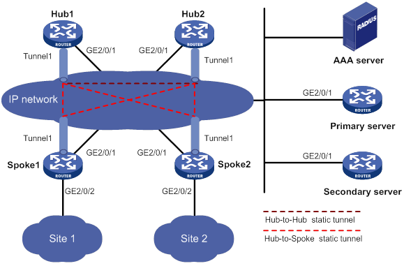
Table 15 Interface and IP address assignment
|
Device |
Interface |
IP address |
Device |
Interface |
IP address |
|
Hub 1 |
GE2/0/1 |
1::1/64 |
Spoke 1 |
GE2/0/1 |
1::3/64 |
|
|
Tunnel1 |
192:168::1/64 |
|
GE2/0/2 |
192:168:1::1/64 |
|
Hub 2 |
GE2/0/1 |
1::2/64 |
|
Tunnel1 |
192:168::3/64 |
|
|
Tunnel1 |
192:168::2/64 |
Spoke 2 |
GE2/0/1 |
1::4/64 |
|
AAA server |
|
1::10/64 |
|
GE2/0/2 |
192:168:2::1/64 |
|
Primary server |
GE2/0/1 |
1::11/64 |
|
Tunnel1 |
192:168::4/64 |
|
Secondary server |
GE2/0/1 |
1::12/64 |
|
|
|
Configuring the primary VAM server
1. Configure IP addresses for the interfaces. (Details not shown.)
2. Configure AAA:
# Configure RADIUS scheme abc.
<PrimaryServer> system-view
[PrimaryServer] radius scheme abc
[PrimaryServer-radius-abc] primary authentication ipv6 1::10 1812
[PrimaryServer-radius-abc] primary accounting ipv6 1::10 1813
[PrimaryServer-radius-abc] key authentication simple 123
[PrimaryServer-radius-abc] key accounting simple 123
[PrimaryServer-radius-abc] user-name-format without-domain
[PrimaryServer-radius-abc] quit
[PrimaryServer] radius session-control enable
# Configure AAA methods for ISP domain abc.
[PrimaryServer] domain abc
[PrimaryServer-isp-abc] authentication advpn radius-scheme abc
[PrimaryServer-isp-abc] accounting advpn radius-scheme abc
[PrimaryServer-isp-abc] quit
[PrimaryServer] domain default enable abc
3. Configure the VAM server:
# Create ADVPN domain abc.
[PrimaryServer] vam server advpn-domain abc id 1
# Create hub group 0.
[PrimaryServer-vam-server-domain-abc] hub-group 0
# Specify hub private IPv6 addresses.
[PrimaryServer-vam-server-domain-abc-hub-group-0] hub ipv6 private-address 192:168::1
[PrimaryServer-vam-server-domain-abc-hub-group-0] hub ipv6 private-address 192:168::2
# Specify a spoke private IPv6 network.
[PrimaryServer-vam-server-domain-abc-hub-group-0] spoke ipv6 private-address network 192:168::0 64
[PrimaryServer-vam-server-domain-abc-hub-group-0] quit
# Set the preshared key to 123456.
[PrimaryServer-vam-server-domain-abc] pre-shared-key simple 123456
# Set the authentication mode to CHAP.
[PrimaryServer-vam-server-domain-abc] authentication-method chap
# Enable the VAM server for the ADVPN domain.
[PrimaryServer-vam-server-domain-abc] server enable
[PrimaryServer-vam-server-domain-abc] quit
Configuring the secondary VAM server
# Configure the secondary VAM server in the same way that the primary server is configured. (Details not shown.)
Configuring Hub 1
1. Configure IP addresses for the interfaces. (Details not shown.)
2. Configure the VAM client:
# Create VAM client Hub1.
<Hub1> system-view
[Hub1] vam client name Hub1
# Specify ADVPN domain abc for the VAM client.
[Hub1-vam-client-Hub1] advpn-domain abc
# Set the preshared key to 123456.
[Hub1-vam-client-Hub1] pre-shared-key simple 123456
# Set the username and password to hub1.
[Hub1-vam-client-Hub1] user hub1 password simple hub1
# Specify the primary and secondary VAM servers.
[Hub1-vam-client-Hub1] server primary ipv6-address 1::11
[Hub1-vam-client-Hub1] server secondary ipv6-address 1::12
# Enable the VAM client.
[Hub1-vam-client-Hub1] client enable
[Hub1-vam-client-Hub1] quit
3. Configure an IPsec profile:
# Configure IKE.
[Hub1] ike keychain abc
[Hub1-ike-keychain-abc] pre-shared-key address ipv6 :: 0 key simple 123456
[Hub1-ike-keychain-abc] quit
[Hub1] ike profile abc
[Hub1-ike-profile-abc] keychain abc
[Hub1-ike-profile-abc] quit
# Configure the IPsec profile.
[Hub1] ipsec transform-set abc
[Hub1-ipsec-transform-set-abc] encapsulation-mode transport
[Hub1-ipsec-transform-set-abc] esp encryption-algorithm des-cbc
[Hub1-ipsec-transform-set-abc] esp authentication-algorithm sha1
[Hub1-ipsec-transform-set-abc] quit
[Hub1] ipsec profile abc isakmp
[Hub1-ipsec-profile-isakmp-abc] transform-set abc
[Hub1-ipsec-profile-isakmp-abc] ike-profile abc
[Hub1-ipsec-profile-isakmp-abc] quit
4. Configure OSPFv3.
[Hub1] ospfv3 1
[Hub1-ospfv3-1] router-id 0.0.0.1
[Hub1-ospfv3-1] area 0
[Hub1-ospfv3-1-area-0.0.0.0] quit
[Hub1-ospfv3-1] quit
5. Configure GRE-mode IPv6 ADVPN tunnel interface tunnel1.
[Hub1] interface tunnel1 mode advpn gre ipv6
[Hub1-Tunnel1] ipv6 address 192:168::1 64
[Hub1-Tunnel1] ipv6 address fe80::1 link-local
[Hub1-Tunnel1] vam ipv6 client Hub1
[Hub1-Tunnel1] ospfv3 1 area 0
[Hub1-Tunnel1] ospfv3 network-type p2mp
[Hub1-Tunnel1] source gigabitethernet 2/0/1
[Hub1-Tunnel1] tunnel protection ipsec profile abc
[Hub1-Tunnel1] quit
Configuring Hub 2
1. Configure IP addresses for the interfaces. (Details not shown.)
2. Configure the VAM client:
# Create VAM client Hub2.
<Hub2> system-view
[Hub2] vam client name Hub2
# Specify ADVPN domain abc for the VAM client.
[Hub2-vam-client-Hub2] advpn-domain abc
# Set the preshared key to 123456.
[Hub2-vam-client-Hub2] pre-shared-key simple 123456
# Set both the username and password to hub2.
[Hub2-vam-client-Hub2] user hub2 password simple hub2
# Specify the primary and secondary VAM servers.
[Hub2-vam-client-Hub2] server primary ipv6-address 1::11
[Hub2-vam-client-Hub2] server secondary ipv6-address 1::12
# Enable the VAM client.
[Hub2-vam-client-Hub2] client enable
[Hub2-vam-client-Hub2] quit
3. Configure an IPsec profile:
# Configure IKE.
[Hub2] ike keychain abc
[Hub2-ike-keychain-abc] pre-shared-key address ipv6 :: 0 key simple 123456
[Hub2-ike-keychain-abc] quit
[Hub2] ike profile abc
[Hub2-ike-profile-abc] keychain abc
[Hub2-ike-profile-abc] quit
# Configure the IPsec profile.
[Hub2] ipsec transform-set abc
[Hub2-ipsec-transform-set-abc] encapsulation-mode transport
[Hub2-ipsec-transform-set-abc] esp encryption-algorithm des-cbc
[Hub2-ipsec-transform-set-abc] esp authentication-algorithm sha1
[Hub2-ipsec-transform-set-abc] quit
[Hub2] ipsec profile abc isakmp
[Hub2-ipsec-profile-isakmp-abc] transform-set abc
[Hub2-ipsec-profile-isakmp-abc] ike-profile abc
[Hub2-ipsec-profile-isakmp-abc] quit
4. Configure OSPFv3.
[Hub2] ospfv3 1
[Hub2-ospfv3-1] router-id 0.0.0.2
[Hub2-ospfv3-1] area 0
[Hub2-ospfv3-1-area-0.0.0.0] quit
[Hub2-ospfv3-1] quit
5. Configure GRE-mode IPv6 ADVPN tunnel interface tunnel1.
[Hub2] interface tunnel1 mode advpn gre ipv6
[Hub2-Tunnel1] ipv6 address 192:168::2 64
[Hub2-Tunnel1] ipv6 address fe80::2 link-local
[Hub2-Tunnel1] vam ipv6 client Hub2
[Hub2-Tunnel1] ospfv3 1 area 0
[Hub2-Tunnel1] ospfv3 network-type p2mp
[Hub2-Tunnel1] source gigabitethernet 2/0/1
[Hub2-Tunnel1] tunnel protection ipsec profile abc
[Hub2-Tunnel1] quit
Configuring Spoke 1
1. Configure IP addresses for the interfaces. (Details not shown.)
2. Configure the VAM client:
# Create VAM client Spoke1.
<Spoke1> system-view
[Spoke1] vam client name Spoke1
# Specify ADVPN domain abc for the VAM client.
[Spoke1-vam-client-Spoke1] advpn-domain abc
# Set the preshared key to 123456.
[Spoke1-vam-client-Spoke1] pre-shared-key simple 123456
# Set both the username and password to spoke1.
[Spoke1-vam-client-Spoke1] user spoke1 password simple spoke1
# Specify the primary and secondary VAM servers.
[Spoke1-vam-client-Spoke1] server primary ipv6-address 1::11
[Spoke1-vam-client-Spoke1] server secondary ipv6-address 1::12
# Enable the VAM client.
[Spoke1-vam-client-Spoke1] client enable
[Spoke1-vam-client-Spoke1] quit
3. Configure an IPsec profile:
# Configure IKE.
[Spoke1] ike keychain abc
[Spoke1-ike-keychain-abc] pre-shared-key address ipv6 :: 0 key simple 123456
[Spoke1-ike-keychain-abc] quit
[Spoke1] ike profile abc
[Spoke1-ike-profile-abc] keychain abc
[Spoke1-ike-profile-abc] quit
# Configure the IPsec profile.
[Spoke1] ipsec transform-set abc
[Spoke1-ipsec-transform-set-abc] encapsulation-mode transport
[Spoke1-ipsec-transform-set-abc] esp encryption-algorithm des-cbc
[Spoke1-ipsec-transform-set-abc] esp authentication-algorithm sha1
[Spoke1-ipsec-transform-set-abc] quit
[Spoke1] ipsec profile abc isakmp
[Spoke1-ipsec-profile-isakmp-abc] transform-set abc
[Spoke1-ipsec-profile-isakmp-abc] ike-profile abc
[Spoke1-ipsec-profile-isakmp-abc] quit
4. Configure OSPFv3.
[Spoke1] ospfv3 1
[Spoke1-ospfv3-1] router-id 0.0.0.3
[Spoke1-ospfv3-1] area 0
[Spoke1-ospfv3-1-area-0.0.0.0] quit
[Spoke1-ospfv3-1] quit
5. Configure GRE-mode IPv6 ADVPN tunnel interface tunnel1.
[Spoke1] interface tunnel1 mode advpn gre ipv6
[Spoke1-Tunnel1] ipv6 address 192:168::3 64
[Spoke1-Tunnel1] ipv6 address fe80::3 link-local
[Spoke1-Tunnel1] vam ipv6 client Spoke1
[Spoke1-Tunnel1] ospfv3 1 area 0
[Spoke1-Tunnel1] ospfv3 network-type p2mp
[Spoke1-Tunnel1] source gigabitethernet 2/0/1
[Spoke1-Tunnel1] tunnel protection ipsec profile abc
[Spoke1-Tunnel1] quit
Configuring Spoke 2
1. Configure IP addresses for the interfaces. (Details not shown.)
2. Configure the VAM client:
# Create VAM client Spoke2.
<Spoke2> system-view
[Spoke2] vam client name Spoke2
# Specify ADVPN domain abc for the VAM client.
[Spoke2-vam-client-Spoke2] advpn-domain abc
# Set the preshared key to 123456.
[Spoke2-vam-client-Spoke2] pre-shared-key simple 123456
# Set both the username and password to spoke2.
[Spoke2-vam-client-Spoke2] user spoke2 password simple spoke2
# Specify the primary and secondary VAM servers.
[Spoke2-vam-client-Spoke2] server primary ipv6-address 1::11
[Spoke2-vam-client-Spoke2] server secondary ipv6-address 1::12
# Enable the VAM client.
[Spoke2-vam-client-Spoke2] client enable
[Spoke2-vam-client-Spoke2] quit
3. Configure an IPsec profile:
# Configure IKE.
[Spoke2] ike keychain abc
[Spoke2-ike-keychain-abc] pre-shared-key address ipv6 :: 0 key simple 123456
[Spoke2-ike-keychain-abc] quit
[Spoke2] ike profile abc
[Spoke2-ike-profile-abc] keychain abc
[Spoke2-ike-profile-abc] quit
# Configure the IPsec profile.
[Spoke2] ipsec transform-set abc
[Spoke2-ipsec-transform-set-abc] encapsulation-mode transport
[Spoke2-ipsec-transform-set-abc] esp encryption-algorithm des-cbc
[Spoke2-ipsec-transform-set-abc] esp authentication-algorithm sha1
[Spoke2-ipsec-transform-set-abc] quit
[Spoke2] ipsec profile abc isakmp
[Spoke2-ipsec-profile-isakmp-abc] transform-set abc
[Spoke2-ipsec-profile-isakmp-abc] ike-profile abc
[Spoke2-ipsec-profile-isakmp-abc] quit
4. Configure OSPFv3.
[Spoke2] ospfv3 1
[Spoke2-ospfv3-1] router-id 0.0.0.4
[Spoke2-ospfv3-1] area 0
[Spoke2-ospfv3-1-area-0.0.0.0] quit
[Spoke2-ospfv3-1] quit
5. Configure GRE-mode IPv6 ADVPN tunnel interface tunnel1.
[Spoke2] interface tunnel1 mode advpn gre ipv6
[Spoke2-Tunnel1] ipv6 address 192:168::4 64
[Spoke2-Tunnel1] ipv6 address fe80::4 link-local
[Spoke2-Tunnel1] vam ipv6 client Spoke2
[Spoke2-Tunnel1] ospfv3 1 area 0
[Spoke2-Tunnel1] ospfv3 network-type p2mp
[Spoke2-Tunnel1] source gigabitethernet 2/0/1
[Spoke2-Tunnel1] tunnel protection ipsec profile abc
[Spoke2-Tunnel1] quit
Verifying the configuration
# Display IPv6 address mapping information for all VAM clients registered with the primary VAM server.
[PrimaryServer] display vam server ipv6 address-map
ADVPN domain name: abc
Total private address mappings: 4
Group Private address Public address Type NAT Holding time
0 192:168::1 1::1 Hub No 0H 52M 7S
0 192:168::2 1::2 Hub No 0H 47M 31S
0 192:168::3 1::3 Spoke No 0H 28M 25S
0 192:168::4 1::4 Spoke No 0H 19M 15S
# Display IPv6 address mapping information for all VAM clients registered with the secondary VAM server.
[SecondaryServer] display vam server ipv6 address-map
ADVPN domain name: abc
Total private address mappings: 4
Group Private address Public address Type NAT Holding time
0 192:168::1 1::1 Hub No 0H 52M 7S
0 192:168::2 1::2 Hub No 0H 47M 31S
0 192:168::3 1::3 Spoke No 0H 28M 25S
0 192:168::4 1::4 Spoke No 0H 19M 15S
The output shows that Hub 1, Hub 2, Spoke 1, Spoke 2, and Spoke 3 all have registered their address mapping information with the VAM servers.
# Display IPv6 ADVPN tunnel information on Hubs. This example uses Hub 1.
[Hub1] display advpn ipv6 session
Interface : Tunnel1
Number of sessions: 3
Private address Public address Port Type State Holding time
192:168::2 1::2 -- H-H Success 0H 46M 8S
192:168::3 1::3 -- H-S Success 0H 27M 27S
192:168::4 1::4 -- H-S Success 0H 18M 18S
The output shows that Hub 1 has established a permanent tunnel to Hub 2, Spoke 1, and Spoke 2.
# Display IPv6 ADVPN tunnel information on Spokes. This example uses Spoke 1.
[Spoke1] display advpn ipv6 session
Interface : Tunnel1
Number of sessions: 2
Private address Public address Port Type State Holding time
192:168::1 1::1 -- S-H Success 0H 46M 8S
192:168::2 1::2 -- S-H Success 0H 46M 8S
The output shows that Spoke 1 has established a permanent hub-spoke tunnel to Hub 1 and Hub 2.
# Verify that Spoke 1 can ping the private address 192:168::4 of Spoke 2.
[Spoke1] ping ipv6 192:168::4
Ping6(56 data bytes) 192:168::3 --> 192:168::4, press CTRL_C to break
56 bytes from 192:168::4, icmp_seq=0 hlim=64 time=3.000 ms
56 bytes from 192:168::4, icmp_seq=1 hlim=64 time=0.000 ms
56 bytes from 192:168::4, icmp_seq=2 hlim=64 time=1.000 ms
56 bytes from 192:168::4, icmp_seq=3 hlim=64 time=1.000 ms
56 bytes from 192:168::4, icmp_seq=4 hlim=64 time=1.000 ms
--- Ping6 statistics for 192:168::4 ---
5 packets transmitted, 5 packets received, 0.0% packet loss
round-trip min/avg/max/std-dev = 0.000/1.200/3.000/0.980 ms
IPv4 multi-hub-group ADVPN configuration example
Network requirements
As shown in Figure 159, the primary and secondary VAM servers manage and maintain VAM client information for all hubs and spokes. The AAA server performs authentication and accounting for VAM clients.
· Configure three hub groups to accommodate all ADVPN nodes:
? Hub group 0 contains Hub 1, Hub 2, and Hub 3.
? Hub group 1 contains Hub 1, Hub 2, Spoke 1, and Spoke 2. Hub 1 and Hub 2 back up each other.
? Hub group 2 contains Hub 3, Spoke 3, and Spoke 4. Hub groups 1 and 2 use full-mesh networking.
· Allow any two spokes to establish a direct spoke-spoke tunnel.
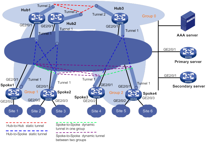
Table 16 Interface and IP address assignment
|
Device |
Interface |
IP address |
Device |
Interface |
IP address |
|
Hub 1 |
GE2/0/1 |
1.0.0.1/24 |
Spoke 1 |
GE2/0/1 |
1.0.0.4/24 |
|
|
Tunnel1 |
192.168.1.1/24 |
|
GE2/0/2 |
192.168.10.1/24 |
|
|
Tunnel2 |
192.168.0.1/24 |
|
Tunnel1 |
192.168.1.3/24 |
|
Hub 2 |
GE2/0/1 |
1.0.0.2/24 |
Spoke 2 |
GE2/0/1 |
1.0.0.5/24 |
|
|
Tunnel1 |
192.168.1.2/24 |
|
GE2/0/2 |
192.168.20.1/24 |
|
|
Tunnel2 |
192.168.0.2/24 |
|
GE2/0/3 |
192.168.30.1/24 |
|
Hub 3 |
GE2/0/1 |
1.0.0.3/24 |
|
Tunnel1 |
192.168.1.4/24 |
|
|
Tunnel1 |
192.168.2.1/24 |
Spoke 3 |
GE2/0/1 |
1.0.0.6/24 |
|
|
Tunnel2 |
192.168.0.3/24 |
|
GE2/0/2 |
192.168.40.1/24 |
|
AAA server |
|
1.0.0.10/24 |
|
Tunnel1 |
192.168.2.2/24 |
|
Primary server |
GE2/0/1 |
1.0.0.11/24 |
Spoke 4 |
GE2/0/1 |
1.0.0.7/24 |
|
Secondary server |
GE2/0/1 |
1.0.0.12/24 |
|
GE2/0/2 |
192.168.50.1/24 |
|
|
|
|
|
GE2/0/3 |
192.168.60.1/24 |
|
|
|
|
|
Tunnel1 |
192.168.2.3/24 |
Configuring the primary VAM server
1. Configure IP addresses for the interfaces. (Details not shown.)
2. Configure AAA:
# Configure RADIUS scheme abc.
<PrimaryServer> system-view
[PrimaryServer] radius scheme abc
[PrimaryServer-radius-abc] primary authentication 1.0.0.10 1812
[PrimaryServer-radius-abc] primary accounting 1.0.0.10 1813
[PrimaryServer-radius-abc] key authentication simple 123
[PrimaryServer-radius-abc] key accounting simple 123
[PrimaryServer-radius-abc] user-name-format without-domain
[PrimaryServer-radius-abc] quit
[PrimaryServer] radius session-control enable
# Configure AAA methods for ISP domain abc.
[PrimaryServer] domain abc
[PrimaryServer-isp-abc] authentication advpn radius-scheme abc
[PrimaryServer-isp-abc] accounting advpn radius-scheme abc
[PrimaryServer-isp-abc] quit
[PrimaryServer] domain default enable abc
3. Configure the VAM server:
# Create ADVPN domain abc.
[PrimaryServer] vam server advpn-domain abc id 1
# Create hub group 0.
[PrimaryServer-vam-server-domain-abc] hub-group 0
# Specify hub private IPv4 addresses.
[PrimaryServer-vam-server-domain-abc-hub-group-0] hub private-address 192.168.0.1
[PrimaryServer-vam-server-domain-abc-hub-group-0] hub private-address 192.168.0.2
[PrimaryServer-vam-server-domain-abc-hub-group-0] hub private-address 192.168.0.3
[PrimaryServer-vam-server-domain-abc-hub-group-0] quit
# Create hub group 1.
[PrimaryServer-vam-server-domain-abc] hub-group 1
# Specify hub private IPv4 addresses.
[PrimaryServer-vam-server-domain-abc-hub-group-1] hub private-address 192.168.1.1
[PrimaryServer-vam-server-domain-abc-hub-group-1] hub private-address 192.168.1.2
# Specify a spoke private IPv4 network.
[PrimaryServer-vam-server-domain-abc-hub-group-1] spoke private-address network 192.168.1.0 255.255.255.0
# Allow establishing direct spoke-spoke tunnels.
[PrimaryServer-vam-server-domain-abc-hub-group-1] shortcut interest all
[PrimaryServer-vam-server-domain-abc-hub-group-1] quit
# Create hub group 2.
[PrimaryServer-vam-server-domain-abc] hub-group 2
# Specify the hub private IPv4 address.
[PrimaryServer-vam-server-domain-abc-hub-group-2] hub private-address 192.168.2.1
# Specify a spoke private IPv4 network.
[PrimaryServer-vam-server-domain-abc-hub-group-2] spoke private-address network 192.168.2.0 255.255.255.0
# Allow establishing direct spoke-spoke tunnels.
[PrimaryServer-vam-server-domain-abc-hub-group-2] shortcut interest all
[PrimaryServer-vam-server-domain-abc-hub-group-2] quit
# Set the preshared key to 123456.
[PrimaryServer-vam-server-domain-abc] pre-shared-key simple 123456
# Set the authentication mode to CHAP.
[PrimaryServer-vam-server-domain-abc] authentication-method chap
# Enable the VAM server for the ADVPN domain.
[PrimaryServer-vam-server-domain-abc] server enable
[PrimaryServer-vam-server-domain-abc] quit
Configuring the secondary VAM server
# Configure the secondary VAM server in the same way that the primary server is configured. (Details not shown.)
Configuring Hub 1
1. Configure IP addresses for the interfaces. (Details not shown.)
2. Configure the VAM client:
# Create VAM client Hub1Group0.
<Hub1> system-view
[Hub1] vam client name Hub1Group0
# Specify ADVPN domain abc for the VAM client.
[Hub1-vam-client-Hub1Group0] advpn-domain abc
# Set the preshared key to 123456.
[Hub1-vam-client-Hub1Group0] pre-shared-key simple 123456
# Set both the username and password to hub1.
[Hub1-vam-client-Hub1Group0] user hub1 password simple hub1
# Specify the primary and secondary VAM servers.
[Hub1-vam-client-Hub1Group0] server primary ip-address 1.0.0.11
[Hub1-vam-client-Hub1Group0] server secondary ip-address 1.0.0.12
# Enable the VAM client.
[Hub1-vam-client-Hub1Group0] client enable
[Hub1-vam-client-Hub1Group0] quit
# Create VAM client Hub1Group1.
[Hub1] vam client name Hub1Group1
# Specify ADVPN domain abc for the VAM client.
[Hub1-vam-client-Hub1Group1] advpn-domain abc
# Set the preshared key to 123456.
[Hub1-vam-client-Hub1Group1] pre-shared-key simple 123456
# Set the username and password to hub1.
[Hub1-vam-client-Hub1Group1] user hub1 password simple hub1
# Specify the primary and secondary VAM servers.
[Hub1-vam-client-Hub1Group1] server primary ip-address 1.0.0.11
[Hub1-vam-client-Hub1Group1] server secondary ip-address 1.0.0.12
# Enable the VAM client.
[Hub1-vam-client-Hub1Group1] client enable
[Hub1-vam-client-Hub1Group1] quit
3. Configure an IPsec profile:
# Configure IKE.
[Hub1] ike keychain abc
[Hub1-ike-keychain-abc] pre-shared-key address 0.0.0.0 0.0.0.0 key simple 123456
[Hub1-ike-keychain-abc] quit
[Hub1] ike profile abc
[Hub1-ike-profile-abc] keychain abc
[Hub1-ike-profile-abc] quit
# Configure the IPsec profile.
[Hub1] ipsec transform-set abc
[Hub1-ipsec-transform-set-abc] encapsulation-mode transport
[Hub1-ipsec-transform-set-abc] esp encryption-algorithm des-cbc
[Hub1-ipsec-transform-set-abc] esp authentication-algorithm sha1
[Hub1-ipsec-transform-set-abc] quit
[Hub1] ipsec profile abc isakmp
[Hub1-ipsec-profile-isakmp-abc] transform-set abc
[Hub1-ipsec-profile-isakmp-abc] ike-profile abc
[Hub1-ipsec-profile-isakmp-abc] quit
4. Configure OSPF to advertise private networks.
[Hub1] ospf 1
[Hub1-ospf-1] area 0
[Hub1-ospf-1-area-0.0.0.0] network 192.168.0.0 0.0.0.255
[Hub1-ospf-1-area-0.0.0.0] quit
[Hub1-ospf-1] area 1
[Hub1-ospf-1-area-0.0.0.1] network 192.168.1.0 0.0.0.255
[Hub1-ospf-1-area-0.0.0.1] quit
[Hub1-ospf-1] quit
5. Configure ADVPN tunnels:
# Configure UDP-mode IPv4 ADVPN tunnel interface tunnel1.
[Hub1] interface tunnel1 mode advpn udp
[Hub1-Tunnel1] ip address 192.168.1.1 255.255.255.0
[Hub1-Tunnel1] vam client Hub1Group1
[Hub1-Tunnel1] ospf network-type
broadcast
[Hub1-Tunnel1] source gigabitethernet 2/0/1
[Hub1-Tunnel1] tunnel protection ipsec profile abc
[Hub1-Tunnel1] quit
# Configure UDP-mode IPv4 ADVPN tunnel interface tunnel2.
[Hub1] interface tunnel2 mode advpn udp
[Hub1-Tunnel2] ip address 192.168.0.1 255.255.255.0
[Hub1-Tunnel2] vam client Hub1Group0
[Hub1-Tunnel2] ospf network-type broadcast
[Hub1-Tunnel2] source gigabitethernet 2/0/1
[Hub1-Tunnel2] tunnel protection ipsec profile abc
[Hub1-Tunnel2] quit
Configuring Hub 2
1. Configure IP addresses for the interfaces. (Details not shown.)
2. Configure the VAM client:
# Create VAM client Hub2Group0.
<Hub2> system-view
[Hub2] vam client name Hub2Group0
# Specify ADVPN domain abc for the VAM client.
[Hub2-vam-client-Hub2Group0] advpn-domain abc
# Set the preshared key to 123456.
[Hub2-vam-client-Hub2Group0] pre-shared-key simple 123456
# Set both the username and password to hub2.
[Hub2-vam-client-Hub2Group0] user hub2 password simple hub2
# Specify the primary and secondary VAM servers.
[Hub2-vam-client-Hub2Group0] server primary ip-address 1.0.0.11
[Hub2-vam-client-Hub2Group0] server secondary ip-address 1.0.0.12
# Enable the VAM client.
[Hub2-vam-client-Hub2Group0] client enable
[Hub2-vam-client-Hub2Group0] quit
# Create VAM client Hub2Group1.
[Hub2] vam client name Hub2Group1
# Specify ADVPN domain abc for the VAM client.
[Hub2-vam-client-Hub2Group1] advpn-domain abc
# Set the preshared key to 123456.
[Hub2-vam-client-Hub2Group1] pre-shared-key simple 123456
# Set both the username and password to hub2.
[Hub2-vam-client-Hub2Group1] user Hub2 password simple Hub2
# Specify the primary and secondary VAM servers.
[Hub2-vam-client-Hub2Group1] server primary ip-address 1.0.0.11
[Hub2-vam-client-Hub2Group1] server secondary ip-address 1.0.0.12
# Enable the VAM client.
[Hub2-vam-client-Hub2Group1] client enable
[Hub2-vam-client-Hub2Group1] quit
3. Configure an IPsec profile:
# Configure IKE.
[Hub2] ike keychain abc
[Hub2-ike-keychain-abc] pre-shared-key address 0.0.0.0 0.0.0.0 key simple 123456
[Hub2-ike-keychain-abc] quit
[Hub2] ike profile abc
[Hub2-ike-profile-abc] keychain abc
[Hub2-ike-profile-abc] quit
# Configure the IPsec profile.
[Hub2] ipsec transform-set abc
[Hub2-ipsec-transform-set-abc] encapsulation-mode transport
[Hub2-ipsec-transform-set-abc] esp encryption-algorithm des-cbc
[Hub2-ipsec-transform-set-abc] esp authentication-algorithm sha1
[Hub2-ipsec-transform-set-abc] quit
[Hub2] ipsec profile abc isakmp
[Hub2-ipsec-profile-isakmp-abc] transform-set abc
[Hub2-ipsec-profile-isakmp-abc] ike-profile abc
[Hub2-ipsec-profile-isakmp-abc] quit
4. Configure OSPF to advertise private networks.
[Hub2] ospf 1
[Hub2-ospf-1] area 0
[Hub2-ospf-1-area-0.0.0.0] network 192.168.0.0 0.0.0.255
[Hub2-ospf-1-area-0.0.0.0] quit
[Hub2-ospf-1] area 1
[Hub2-ospf-1-area-0.0.0.1] network 192.168.1.0 0.0.0.255
[Hub2-ospf-1-area-0.0.0.1] quit
[Hub2-ospf-1] quit
5. Configure ADVPN tunnels:
# Configure UDP-mode IPv4 ADVPN tunnel interface tunnel1.
[Hub2] interface tunnel 1 mode advpn gre
[Hub2-Tunnel1] ip address 192.168.0.2 255.255.255.0
[Hub2-Tunnel1] vam client Hub2
[Hub2-Tunnel1] ospf network-type broadcast
[Hub2-Tunnel1] source gigabitethernet 2/0/1
[Hub2-Tunnel1] tunnel protection ipsec profile abc
[Hub2-Tunnel1] quit
# Configure UDP-mode IPv4 ADVPN tunnel interface tunnel2.
[Hub2] interface tunnel2 mode advpn udp
[Hub2-Tunnel2] ip address 192.168.0.2 255.255.255.0
[Hub2-Tunnel2] vam client Hub2Group0
[Hub2-Tunnel2] ospf network-type broadcast
[Hub2-Tunnel2] source gigabitethernet 2/0/1
[Hub2-Tunnel2] tunnel protection ipsec profile abc
[Hub2-Tunnel2] quit
Configuring Hub 3
1. Configure IP addresses for the interfaces. (Details not shown.)
2. Configure the VAM client:
# Create VAM client Hub3Group0.
<Hub3> system-view
[Hub3] vam client name Hub3Group0
# Specify ADVPN domain abc for the VAM client.
[Hub3-vam-client-Hub3Group0] advpn-domain abc
# Set the preshared key to 123456.
[Hub3-vam-client-Hub3Group0] pre-shared-key simple 123456
# Set both the username and password to hub3.
[Hub3-vam-client-Hub3Group0] user hub3 password simple hub3
# Specify the primary and secondary VAM servers.
[Hub2-vam-client-Hub2Group0] server primary ip-address 1.0.0.11
[Hub2-vam-client-Hub2Group0] server secondary ip-address 1.0.0.12
# Enable the VAM client.
[Hub2-vam-client-Hub2Group0] client enable
[Hub2-vam-client-Hub2Group0] quit
# Create VAM client Hub3Group1.
[Hub3] vam client name Hub3Group1
# Specify ADVPN domain abc for the VAM client.
[Hub3-vam-client-Hub3Group1] advpn-domain abc
# Set the preshared key to 123456.
[Hub3-vam-client-Hub3Group1] pre-shared-key simple 123456
# Set both the username and password to hub3.
[Hub3-vam-client-Hub3Group1] user hub3 password simple hub3
# Specify the primary and secondary VAM servers.
[Hub3-vam-client-Hub3Group1] server primary ip-address 1.0.0.11
[Hub3-vam-client-Hub3Group1] server secondary ip-address 1.0.0.12
# Enable the VAM client.
[Hub2-vam-client-Hub2Group1] client enable
[Hub2-vam-client-Hub2Group1] quit
3. Configure an IPsec profile:
# Configure IKE.
[Hub3] ike keychain abc
[Hub3-ike-keychain-abc] pre-shared-key address 0.0.0.0 0.0.0.0 key simple 123456
[Hub3-ike-keychain-abc] quit
[Hub3] ike profile abc
[Hub3-ike-profile-abc] keychain abc
[Hub3-ike-profile-abc] quit
# Configure the IPsec profile.
[Hub3] ipsec transform-set abc
[Hub3-ipsec-transform-set-abc] encapsulation-mode transport
[Hub3-ipsec-transform-set-abc] esp encryption-algorithm des-cbc
[Hub3-ipsec-transform-set-abc] esp authentication-algorithm sha1
[Hub3-ipsec-transform-set-abc] quit
[Hub3] ipsec profile abc isakmp
[Hub3-ipsec-profile-isakmp-abc] transform-set abc
[Hub3-ipsec-profile-isakmp-abc] ike-profile abc
[Hub3-ipsec-profile-isakmp-abc] quit
4. Configure OSPF to advertise private networks.
[Hub3] ospf 1
[Hub3-ospf-1] area 0
[Hub3-ospf-1-area-0.0.0.0] network 192.168.0.0 0.0.0.255
[Hub3-ospf-1-area-0.0.0.0] quit
[Hub3-ospf-1] area 2
[Hub3-ospf-1-area-0.0.0.2] network 192.168.2.0 0.0.0.255
[Hub3-ospf-1-area-0.0.0.2] quit
[Hub3-ospf-1] quit
5. Configure ADVPN tunnels:
# Configure UDP-mode IPv4 ADVPN tunnel interface tunnel1.
[Hub3] interface tunnel1 mode advpn udp
[Hub3-Tunnel1] ip address 192.168.2.1 255.255.255.0
[Hub3-Tunnel1] vam client Hub3Group1
[Hub3-Tunnel1] ospf network-type broadcast
[Hub3-Tunnel1] source gigabitethernet 2/0/1
[Hub3-Tunnel1] tunnel protection ipsec profile abc
[Hub3-Tunnel1] quit
# Configure UDP-mode IPv4 ADVPN tunnel interface tunnel2.
[Hub3] interface tunnel2 mode advpn udp
[Hub3-Tunnel2] ip address 192.168.0.3 255.255.255.0
[Hub3-Tunnel2] vam client Hub3Group0
[Hub3-Tunnel2] ospf network-type broadcast
[Hub3-Tunnel2] source gigabitethernet 2/0/1
[Hub3-Tunnel2] tunnel protection ipsec profile abc
[Hub3-Tunnel2] quit
Configuring Spoke 1
1. Configure IP addresses for the interfaces. (Details not shown.)
2. Configure the VAM client:
# Create VAM client Spoke1.
<Spoke1> system-view
[Spoke1] vam client name Spoke1
# Specify ADVPN domain abc for the VAM client.
[Spoke1-vam-client-Spoke1] advpn-domain abc
# Set the preshared key to 123456.
[Spoke1-vam-client-Spoke1] pre-shared-key simple 123456
# Set both the username and password to spoke1.
[Spoke1-vam-client-Spoke1] user spoke1 password simple spoke1
# Specify the primary and secondary VAM servers.
[Spoke1-vam-client-Spoke1] server primary ip-address 1.0.0.11
[Spoke1-vam-client-Spoke1] server secondary ip-address 1.0.0.12
# Enable the VAM client.
[Spoke1-vam-client-Spoke1] client enable
[Spoke1-vam-client-Spoke1] quit
3. Configure an IPsec profile:
# Configure IKE.
[Spoke1] ike keychain abc
[Spoke1-ike-keychain-abc] pre-shared-key address 0.0.0.0 0.0.0.0 key simple 123456
[Spoke1-ike-keychain-abc] quit
[Spoke1] ike profile abc
[Spoke1-ike-profile-abc] keychain abc
[Spoke1-ike-profile-abc] quit
# Configure the IPsec profile.
[Spoke1] ipsec transform-set abc
[Spoke1-ipsec-transform-set-abc] encapsulation-mode transport
[Spoke1-ipsec-transform-set-abc] esp encryption-algorithm des-cbc
[Spoke1-ipsec-transform-set-abc] esp authentication-algorithm sha1
[Spoke1-ipsec-transform-set-abc] quit
[Spoke1] ipsec profile abc isakmp
[Spoke1-ipsec-profile-isakmp-abc] transform-set abc
[Spoke1-ipsec-profile-isakmp-abc] ike-profile abc
[Spoke1-ipsec-profile-isakmp-abc] quit
4. Configure OSPF to advertise private networks.
[Spoke1] ospf 1
[Spoke1-ospf-1] area 1
[Spoke1-ospf-1-area-0.0.0.1] network 192.168.1.0 0.0.0.255
[Spoke1-ospf-1-area-0.0.0.1] network 192.168.10.0 0.0.0.255
[Spoke1-ospf-1-area-0.0.0.1] quit
[Spoke1-ospf-1] quit
5. Configure UDP-mode IPv4 ADVPN tunnel interface tunnel1. Configure its DR priority as 0 so Spoke 1 will not participate in DR/BDR election.
[Spoke1] interface tunnel1 mode advpn udp
[Spoke1-Tunnel1] ip address 192.168.1.3 255.255.255.0
[Spoke1-Tunnel1] vam client Spoke1
[Spoke1-Tunnel1] ospf network-type broadcast
[Spoke1-Tunnel1] ospf dr-priority 0
[Spoke1-Tunnel1] advpn network 192.168.10.0 255.255.255.0
[Spoke1-Tunnel1] source gigabitethernet 2/0/1
[Spoke1-Tunnel1] tunnel protection ipsec profile abc
[Spoke1-Tunnel1] quit
Configuring Spoke 2
1. Configure IP addresses for the interfaces. (Details not shown.)
2. Configure the VAM client:
# Create VAM client Spoke2.
<Spoke2> system-view
[Spoke2] vam client name Spoke2
# Specify ADVPN domain abc for the VAM client.
[Spoke2-vam-client-Spoke2] advpn-domain abc
# Set the preshared key to 123456.
[Spoke2-vam-client-Spoke2] pre-shared-key simple 123456
# Set both the username and password to spoke2.
[Spoke2-vam-client-Spoke2] user spoke2 password simple spoke2
# Specify the primary and secondary VAM servers.
[Spoke2-vam-client-Spoke2] server primary ip-address 1.0.0.11
[Spoke2-vam-client-Spoke2] server secondary ip-address 1.0.0.12
# Enable the VAM client.
[Spoke2-vam-client-Spoke2] client enable
[Spoke2-vam-client-Spoke2] quit
3. Configure an IPsec profile:
# Configure IKE.
[Spoke2] ike keychain abc
[Spoke2-ike-keychain-abc] pre-shared-key address 0.0.0.0 0.0.0.0 key simple 123456
[Spoke2-ike-keychain-abc] quit
[Spoke2] ike profile abc
[Spoke2-ike-profile-abc] keychain abc
[Spoke2-ike-profile-abc] quit
# Configure the IPsec profile.
[Spoke2] ipsec transform-set abc
[Spoke2-ipsec-transform-set-abc] encapsulation-mode transport
[Spoke2-ipsec-transform-set-abc] esp encryption-algorithm des-cbc
[Spoke2-ipsec-transform-set-abc] esp authentication-algorithm sha1
[Spoke2-ipsec-transform-set-abc] quit
[Spoke2] ipsec profile abc isakmp
[Spoke2-ipsec-profile-isakmp-abc] transform-set abc
[Spoke2-ipsec-profile-isakmp-abc] ike-profile abc
[Spoke2-ipsec-profile-isakmp-abc] quit
4. Configure OSPF to advertise private networks.
[Spoke2] ospf 1
[Spoke2-ospf-1] area 1
[Spoke2-ospf-1-area-0.0.0.1] network 192.168.1.0 0.0.0.255
[Spoke2-ospf-1-area-0.0.0.1] network 192.168.20.0 0.0.0.255
[Spoke2-ospf-1-area-0.0.0.1] network 192.168.30.0 0.0.0.255
[Spoke2-ospf-1-area-0.0.0.1] quit
[Spoke2-ospf-1] quit
5. Configure UDP-mode IPv4 ADVPN tunnel interface tunnel1. Configure its DR priority as 0 so Spoke 2 will not participate in DR/BDR election.
[Spoke2] interface tunnel1 mode advpn udp
[Spoke2-Tunnel1] ip address 192.168.1.4 255.255.255.0
[Spoke2-Tunnel1] vam client Spoke2
[Spoke2-Tunnel1] ospf network-type broadcast
[Spoke2-Tunnel1] ospf dr-priority 0
[Spoke2-Tunnel1] advpn network 192.168.20.0 255.255.255.0
[Spoke2-Tunnel1] advpn network 192.168.30.0 255.255.255.0
[Spoke2-Tunnel1] source gigabitethernet 2/0/1
[Spoke2-Tunnel1] tunnel protection ipsec profile abc
[Spoke2-Tunnel1] quit
Configuring Spoke 3
1. Configure IP addresses for the interfaces. (Details not shown.)
2. Configure the VAM client:
# Create VAM client Spoke3.
<Spoke3> system-view
[Spoke3] vam client name Spoke3
# Specify ADVPN domain abc for the VAM client.
[Spoke3-vam-client-Spoke3] advpn-domain abc
# Set the preshared key to 123456.
[Spoke3-vam-client-Spoke3] pre-shared-key simple 123456
# Set both the username and password to spoke3.
[Spoke3-vam-client-Spoke3] user spoke3 password simple spoke3
# Specify the primary and secondary VAM servers.
[Spoke3-vam-client-Spoke3] server primary ip-address 1.0.0.11
[Spoke3-vam-client-Spoke3] server secondary ip-address 1.0.0.12
# Enable the VAM client.
[Spoke3-vam-client-Spoke3] client enable
[Spoke3-vam-client-Spoke3] quit
3. Configure an IPsec profile:
# Configure IKE.
[Spoke3] ike keychain abc
[Spoke3-ike-keychain-abc] pre-shared-key address 0.0.0.0 0.0.0.0 key simple 123456
[Spoke3-ike-keychain-abc] quit
[Spoke3] ike profile abc
[Spoke3-ike-profile-abc] keychain abc
[Spoke3-ike-profile-abc] quit
# Configure the IPsec profile.
[Spoke3] ipsec transform-set abc
[Spoke3-ipsec-transform-set-abc] encapsulation-mode transport
[Spoke3-ipsec-transform-set-abc] esp encryption-algorithm des-cbc
[Spoke3-ipsec-transform-set-abc] esp authentication-algorithm sha1
[Spoke3-ipsec-transform-set-abc] quit
[Spoke3] ipsec profile abc isakmp
[Spoke3-ipsec-profile-isakmp-abc] transform-set abc
[Spoke3-ipsec-profile-isakmp-abc] ike-profile abc
[Spoke3-ipsec-profile-isakmp-abc] quit
4. Configure OSPF to advertise private networks.
[Spoke3] ospf 1
[Spoke3-ospf-1] area 2
[Spoke3-ospf-1-area-0.0.0.2] network 192.168.2.0 0.0.0.255
[Spoke3-ospf-1-area-0.0.0.2] network 192.168.40.0 0.0.0.255
[Spoke3-ospf-1-area-0.0.0.2] quit
[Spoke3-ospf-1] quit
5. Configure UDP-mode IPv4 ADVPN tunnel interface tunnel1. Configure its DR priority as 0 so Spoke 3 will not participate in DR/BDR election.
[Spoke3] interface tunnel 1 mode advpn udp
[Spoke3-Tunnel1] ip address 192.168.2.2 255.255.255.0
[Spoke3-Tunnel1] vam client Spoke3
[Spoke3-Tunnel1] ospf network-type broadcast
[Spoke3-Tunnel1] ospf dr-priority 0
[Spoke3-Tunnel1] advpn network 192.168.40.0 255.255.255.0
[Spoke3-Tunnel1] source gigabitethernet 2/0/1
[Spoke3-Tunnel1] tunnel protection ipsec profile abc
[Spoke3-Tunnel1] quit
Configuring Spoke 4
1. Configure IP addresses for the interfaces. (Details not shown.)
2. Configure the VAM client:
# Create VAM client Spoke4.
<Spoke4> system-view
[Spoke4] vam client name Spoke4
# Specify ADVPN domain abc for the VAM client.
[Spoke4-vam-client-Spoke4] advpn-domain abc
# Set the preshared key to 123456.
[Spoke4-vam-client-Spoke4] pre-shared-key simple 123456
# Set both the username and password to spoke4.
[Spoke4-vam-client-Spoke4] user spoke4 password simple spoke4
# Specify the primary and secondary VAM servers.
[Spoke4-vam-client-Spoke4] server primary ip-address 1.0.0.11
[Spoke4-vam-client-Spoke4] server secondary ip-address 1.0.0.12
# Enable the VAM client.
[Spoke4-vam-client-Spoke4] client enable
[Spoke4-vam-client-Spoke4] quit
3. Configure an IPsec profile:
# Configure IKE.
[Spoke4] ike keychain abc
[Spoke4-ike-keychain-abc] pre-shared-key address 0.0.0.0 0.0.0.0 key simple 123456
[Spoke4-ike-keychain-abc] quit
[Spoke4] ike profile abc
[Spoke4-ike-profile-abc] keychain abc
[Spoke4-ike-profile-abc] quit
# Configure the IPsec profile.
[Spoke4] ipsec transform-set abc
[Spoke4-ipsec-transform-set-abc] encapsulation-mode transport
[Spoke4-ipsec-transform-set-abc] esp encryption-algorithm des-cbc
[Spoke4-ipsec-transform-set-abc] esp authentication-algorithm sha1
[Spoke4-ipsec-transform-set-abc] quit
[Spoke4] ipsec profile abc isakmp
[Spoke4-ipsec-profile-isakmp-abc] transform-set abc
[Spoke4-ipsec-profile-isakmp-abc] ike-profile abc
[Spoke4-ipsec-profile-isakmp-abc] quit
4. Configure OSPF to advertise private networks.
[Spoke4] ospf 1
[Spoke4-ospf-1] area 2
[Spoke4-ospf-1-area-0.0.0.2] network 192.168.2.0 0.0.0.255
[Spoke4-ospf-1-area-0.0.0.2] network 192.168.50.0 0.0.0.255
[Spoke4-ospf-1-area-0.0.0.2] network 192.168.60.0 0.0.0.255
[Spoke4-ospf-1-area-0.0.0.2] quit
[Spoke4-ospf-1] quit
5. Configure UDP-mode IPv4 ADVPN tunnel interface tunnel1. Configure its DR priority as 0 so Spoke 4 will not participate in DR/BDR election.
[Spoke4] interface tunnel1 mode advpn udp
[Spoke4-Tunnel1] ip address 192.168.2.3 255.255.255.0
[Spoke4-Tunnel1] vam client Spoke4
[Spoke4-Tunnel1] ospf network-type broadcast
[Spoke4-Tunnel1] ospf dr-priority 0
[Spoke4-Tunnel1] advpn network 192.168.50.0 255.255.255.0
[Spoke4-Tunnel1] advpn network 192.168.60.0 255.255.255.0
[Spoke4-Tunnel1] source gigabitethernet 2/0/1
[Spoke4-Tunnel1] tunnel protection ipsec profile abc
[Spoke4-Tunnel1] quit
Verifying the configuration
# Display IPv4 address mapping information for all VAM clients registered with the primary VAM server.
[PrimaryServer] display vam server address-map
ADVPN domain name: abc
Total private address mappings: 10
Group Private address Public address Type NAT Holding time
0 192.168.0.1 1.0.0.1 Hub No 0H 52M 7S
0 192.168.0.2 1.0.0.2 Hub No 0H 47M 31S
0 192.168.0.3 1.0.0.3 Hub No 0H 28M 25S
1 192.168.1.1 1.0.0.1 Hub No 0H 52M 7S
1 192.168.1.2 1.0.0.2 Hub No 0H 47M 31S
1 192.168.1.3 1.0.0.4 Spoke No 0H 18M 26S
1 192.168.1.4 1.0.0.5 Spoke No 0H 28M 25S
2 192.168.2.1 1.0.0.3 Hub No 0H 28M 25S
2 192.168.2.2 1.0.0.6 Spoke No 0H 25M 40S
2 192.168.2.3 1.0.0.7 Spoke No 0H 25M 31S
# Display IPv4 address mapping information for all VAM clients registered with the secondary VAM server.
[SecondaryServer] display vam server address-map
ADVPN domain name: abc
Total private address mappings: 10
Group Private address Public address Type NAT Holding time
0 192.168.0.1 1.0.0.1 Hub No 0H 52M 7S
0 192.168.0.2 1.0.0.2 Hub No 0H 47M 31S
0 192.168.0.3 1.0.0.3 Hub No 0H 28M 25S
1 192.168.1.1 1.0.0.1 Hub No 0H 52M 7S
1 192.168.1.2 1.0.0.2 Hub No 0H 47M 31S
1 192.168.1.3 1.0.0.4 Spoke No 0H 18M 26S
1 192.168.1.4 1.0.0.5 Spoke No 0H 28M 25S
2 192.168.2.1 1.0.0.3 Hub No 0H 28M 25S
2 192.168.2.2 1.0.0.6 Spoke No 0H 25M 40S
2 192.168.2.3 1.0.0.7 Spoke No 0H 25M 31S
The output shows that Hub 1, Hub 2, Hub3, Spoke 1, Spoke 2, Spoke 3, and Spoke4 all have registered their address mapping information with the VAM servers.
# Display IPv4 ADVPN tunnel information on Hubs. This example uses Hub 1.
[Hub1] display advpn session
Interface : Tunnel1
Number of sessions: 3
Private address Public address Port Type State Holding time
192.168.1.2 1.0.0.2 18001 H-H Success 0H 46M 8S
192.168.1.3 1.0.0.3 18001 H-S Success 0H 27M 27S
192.168.1.4 1.0.0.4 18001 H-S Success 0H 18M 18S
Interface : Tunnel2
Number of sessions: 2
Private address Public address Port Type State Holding time
192.168.0.2 1.0.0.2 18001 H-H Success 0H 46M 8S
192.168.0.3 1.0.0.3 18001 H-H Success 0H 27M 27S
The output shows that Hub 1 has established a permanent tunnel to Hub 2, Hub3, Spoke 1, and Spoke 2.
# Display IPv4 ADVPN tunnel information on Spoke 1 and Spoke 2. This example uses Spoke 1.
[Spoke1] display advpn session
Interface : Tunnel1
Number of sessions: 2
Private address Public address Port Type State Holding time
192.168.1.1 1.0.0.1 18001 S-H Success 0H 46M 8S
192.168.1.2 1.0.0.2 18001 S-H Success 0H 46M 8S
The output shows that Spoke 1 has established a permanent hub-spoke tunnel to Hub 1 and Hub 2.
# Display IPv4 ADVPN tunnel information on Spoke 3 and Spoke 4. This example uses Spoke 3.
[Spoke3] display advpn session
Interface : Tunnel1
Number of sessions: 1
Private address Public address Port Type State Holding time
192.168.2.1 1.0.0.3 18001 S-H Success 0H 46M 8S
The output shows that Spoke 3 has established a permanent hub-spoke tunnel to Hub 3.
IPv6 multi-hub-group ADVPN configuration example
Network requirements
As shown in Figure 160, the primary and secondary VAM servers manage and maintain VAM client information for all hubs and spokes. The AAA server performs authentication and accounting for VAM clients.
· Configure three hub groups to accommodate all ADVPN nodes:
? Hub group 0 contains Hub1, Hub2, and Hub3.
? Hub group 1 contains Hub1, Hub2, Spoke1, and Spoke2. Hub 1 and Hub 2 back up each other.
? Hub group 2 contains Hub3, Spoke3, and Spoke4. Hub groups 1 and 2 use full-mesh networking.
· Allow any two spokes to establish a direct spoke-spoke tunnel.
Table 17 Interface and IP address assignment
|
Device |
Interface |
IP address |
Device |
Interface |
IP address |
|
Hub 1 |
GE2/0/1 |
1::1/64 |
Spoke 1 |
GE2/0/1 |
1::4/64 |
|
|
Tunnel1 |
192:168:1::1/64 |
|
GE2/0/2 |
192:168:10::1/64 |
|
|
Tunnel2 |
192:168::1/64 |
|
Tunnel1 |
192:168:1::3/64 |
|
Hub 2 |
GE2/0/1 |
1::2/64 |
Spoke 2 |
GE2/0/1 |
1::5/64 |
|
|
Tunnel1 |
192:168:1::2/64 |
|
GE2/0/2 |
192:168:20::1/64 |
|
|
Tunnel2 |
192:168::2/64 |
|
GE2/0/3 |
192:168:30::1/64 |
|
Hub 3 |
GE2/0/1 |
1::3/64 |
|
Tunnel1 |
192:168:1::4/64 |
|
|
Tunnel1 |
192:168:2::1/64 |
Spoke 3 |
GE2/0/1 |
1::6/64 |
|
|
Tunnel2 |
192:168::3/64 |
|
GE2/0/2 |
192:168:40::1/64 |
|
AAA server |
|
1::10/64 |
|
Tunnel1 |
192:168:2::2/64 |
|
Primary server |
GE2/0/1 |
1::11/64 |
Spoke 4 |
GE2/0/1 |
1::7/64 |
|
Secondary server |
GE2/0/1 |
1::12/64 |
|
GE2/0/2 |
192:168:50::1/64 |
|
|
|
|
|
GE2/0/3 |
192:168:60::1/64 |
|
|
|
|
|
Tunnel1 |
192:168:2::3/64 |
Configuring the primary VAM server
1. Configure IP addresses for the interfaces. (Details not shown.)
2. Configure AAA:
# Configure RADIUS scheme abc.
<PrimaryServer> system-view
[PrimaryServer] radius scheme abc
[PrimaryServer-radius-abc] primary authentication ipv6 1::10 1812
[PrimaryServer-radius-abc] primary accounting ipv6 1::10 1813
[PrimaryServer-radius-abc] key authentication simple 123
[PrimaryServer-radius-abc] key accounting simple 123
[PrimaryServer-radius-abc] user-name-format without-domain
[PrimaryServer-radius-abc] quit
[PrimaryServer] radius session-control enable
# Configure AAA methods for ISP domain abc.
[PrimaryServer] domain abc
[PrimaryServer-isp-abc] authentication advpn radius-scheme abc
[PrimaryServer-isp-abc] accounting advpn radius-scheme abc
[PrimaryServer-isp-abc] quit
[PrimaryServer] domain default enable abc
3. Configure the VAM server:
# Create ADVPN domain abc.
[PrimaryServer] vam server advpn-domain abc id 1
# Create hub group 0.
[PrimaryServer-vam-server-domain-abc] hub-group 0
# Specify hub private IPv6 addresses.
[PrimaryServer-vam-server-domain-abc-hub-group-0] hub ipv6 private-address 192:168::1
[PrimaryServer-vam-server-domain-abc-hub-group-0] hub ipv6 private-address 192:168::2
[PrimaryServer-vam-server-domain-abc-hub-group-0] hub ipv6 private-address 192:168::3
[PrimaryServer-vam-server-domain-abc-hub-group-0] quit
# Create hub group 1.
[PrimaryServer-vam-server-domain-abc] hub-group 1
# Specify hub private IPv6 addresses.
[PrimaryServer-vam-server-domain-abc-hub-group-1] hub ipv6 private-address 192:168:1::1
[PrimaryServer-vam-server-domain-abc-hub-group-1] hub ipv6 private-address 192:168:1::2
# Specify a spoke private IPv6 network.
[PrimaryServer-vam-server-domain-abc-hub-group-1] spoke ipv6 private-address network 192:168:1::0 64
# Allow establishing spoke-spoke tunnels.
[PrimaryServer-vam-server-domain-abc-hub-group-1] shortcut ipv6 interest all
[PrimaryServer-vam-server-domain-abc-hub-group-1] quit
# Create hub group 2.
[PrimaryServer-vam-server-domain-abc] hub-group 2
# Specify the hub private IPv6 address.
[PrimaryServer-vam-server-domain-abc-hub-group-2] hub ipv6 private-address 192:168:2::1
# Specify a spoke private IPv6 network.
[PrimaryServer-vam-server-domain-abc-hub-group-2] spoke ipv6 private-address network 192:168:2::0 64
[PrimaryServer-vam-server-domain-abc-hub-group-2] quit
# Set the preshared key to 123456.
[PrimaryServer-vam-server-domain-abc] pre-shared-key simple 123456
# Set the authentication mode to CHAP.
[PrimaryServer-vam-server-domain-abc] authentication-method chap
# Enable the VAM server for the ADVPN domain.
[PrimaryServer-vam-server-domain-abc] server enable
[PrimaryServer-vam-server-domain-abc] quit
Configuring the secondary VAM server
# Configure the secondary VAM server in the same way that the primary server is configured. (Details not shown.)
Configuring Hub 1
1. Configure IP addresses for the interfaces. (Details not shown.)
2. Configure the VAM client:
# Create VAM client Hub1Group0.
<Hub1> system-view
[Hub1] vam client name Hub1Group0
# Specify ADVPN domain abc for the VAM client.
[Hub1-vam-client-Hub1Group0] advpn-domain abc
# Set the preshared key to 123456.
[Hub1-vam-client-Hub1Group0] pre-shared-key simple 123456
# Set both the username and password to hub1.
[Hub1-vam-client-Hub1Group0] user hub1 password simple hub1
# Specify the primary and secondary VAM servers.
[Hub1-vam-client-Hub1Group0] server primary ipv6-address 1::11
[Hub1-vam-client-Hub1Group0] server secondary ipv6-address 1::12
# Enable the VAM client.
[Hub1-vam-client-Hub1Group0] client enable
[Hub1-vam-client-Hub1Group0] quit
# Create VAM client Hub1Group1.
[Hub1] vam client name Hub1Group1
# Specify ADVPN domain abc for the VAM client.
[Hub1-vam-client-Hub1Group1] advpn-domain abc
# Set the preshared key to 123456.
[Hub1-vam-client-Hub1Group1] pre-shared-key simple 123456
# Set both the username and password to hub1.
[Hub1-vam-client-Hub1Group1] user hub1 password simple hub1
# Specify the primary and secondary VAM servers.
[Hub1-vam-client-Hub1Group1] server primary ipv6-address 1::11
[Hub1-vam-client-Hub1Group1] server secondary ipv6-address 1::12
# Enable the VAM client.
[Hub1-vam-client-Hub1Group1] client enable
[Hub1-vam-client-Hub1Group1] quit
3. Configure an IPsec profile:
# Configure IKE.
[Hub1] ike keychain abc
[Hub1-ike-keychain-abc] pre-shared-key address ipv6 :: 0 key simple 123456
[Hub1-ike-keychain-abc] quit
[Hub1] ike profile abc
[Hub1-ike-profile-abc] keychain abc
[Hub1-ike-profile-abc] quit
# Configure the IPsec profile.
[Hub1] ipsec transform-set abc
[Hub1-ipsec-transform-set-abc] encapsulation-mode transport
[Hub1-ipsec-transform-set-abc] esp encryption-algorithm des-cbc
[Hub1-ipsec-transform-set-abc] esp authentication-algorithm sha1
[Hub1-ipsec-transform-set-abc] quit
[Hub1] ipsec profile abc isakmp
[Hub1-ipsec-profile-isakmp-abc] transform-set abc
[Hub1-ipsec-profile-isakmp-abc] ike-profile abc
[Hub1-ipsec-profile-isakmp-abc] quit
4. Configure OSPFv3.
[Hub1] ospfv3 1
[Hub1-ospfv3-1] router-id 0.0.0.1
[Hub1-ospfv3-1] area 0
[Hub1-ospfv3-1-area-0.0.0.0] quit
[Hub1-ospfv3-1] area 1
[Hub1-ospfv3-1-area-0.0.0.1] quit
[Hub1-ospfv3-1] quit
5. Configure ADVPN tunnels:
# Configure UDP-mode IPv6 ADVPN tunnel interface tunnel1.
[Hub1] interface tunnel1 mode advpn udp ipv6
[Hub1-Tunnel1] ipv6 address 192:168:1::1 64
[Hub1-Tunnel1] ipv6 address fe80::1:1 link-local
[Hub1-Tunnel1] vam ipv6 client Hub1Group1
[Hub1-Tunnel1] ospfv3 1 area 1
[Hub1-Tunnel1] ospfv3 network-type broadcast
[Hub1-Tunnel1] source gigabitethernet 2/0/1
[Hub1-Tunnel1] tunnel protection ipsec profile abc
[Hub1-Tunnel1] quit
# Configure UDP-mode IPv6 ADVPN tunnel interface tunnel2.
[Hub1] interface tunnel2 mode advpn udp ipv6
[Hub1-Tunnel2] ipv6 address 192:168::1 64
[Hub1-Tunnel2] ipv6 address fe80::1 link-local
[Hub1-Tunnel2] vam ipv6 client Hub1Group0
[Hub1-Tunnel2] ospfv3 1 area 0
[Hub1-Tunnel2] ospfv3 network-type broadcast
[Hub1-Tunnel2] source gigabitethernet 2/0/1
[Hub1-Tunnel2] tunnel protection ipsec profile abc
[Hub1-Tunnel2] quit
Configuring Hub 2
1. Configure IP addresses for the interfaces. (Details not shown.)
2. Configure the VAM client:
# Create VAM client Hub2Group0.
<Hub2> system-view
[Hub2] vam client name Hub2Group0
# Specify ADVPN domain abc for the VAM client.
[Hub2-vam-client-Hub2Group0] advpn-domain abc
# Set the preshared key to 123456.
[Hub2-vam-client-Hub2Group0] pre-shared-key simple 123456
# Set both the username and password to hub2.
[Hub2-vam-client-Hub2Group0] user hub2 password simple hub2
# Specify the primary and secondary VAM servers.
[Hub2-vam-client-Hub2Group0] server primary ipv6-address 1::11
[Hub2-vam-client-Hub2Group0] server secondary ipv6-address 1::12
# Enable the VAM client.
[Hub2-vam-client-Hub2Group0] client enable
[Hub2-vam-client-Hub2Group0] quit
# Create VAM client Hub2Group1.
[Hub2] vam client name Hub2Group1
# Specify ADVPN domain abc for the VAM client.
[Hub2-vam-client-Hub2Group1] advpn-domain abc
# Set the preshared key to 123456.
[Hub2-vam-client-Hub2Group1] pre-shared-key simple 123456
# Set both the username and password to hub2.
[Hub2-vam-client-Hub2Group1] user Hub2 password simple Hub2
# Specify the primary and secondary VAM servers.
[Hub2-vam-client-Hub2Group1] server primary ipv6-address 1::11
[Hub2-vam-client-Hub2Group1] server secondary ipv6-address 1::12
# Enable the VAM client.
[Hub2-vam-client-Hub2Group1] client enable
[Hub2-vam-client-Hub2Group1] quit
3. Configure an IPsec profile:
# Configure IKE.
[Hub2] ike keychain abc
[Hub2-ike-keychain-abc] pre-shared-key address ipv6 :: 0 key simple 123456
[Hub2-ike-keychain-abc] quit
[Hub2] ike profile abc
[Hub2-ike-profile-abc] keychain abc
[Hub2-ike-profile-abc] quit
# Configure the IPsec profile.
[Hub2] ipsec transform-set abc
[Hub2-ipsec-transform-set-abc] encapsulation-mode transport
[Hub2-ipsec-transform-set-abc] esp encryption-algorithm des-cbc
[Hub2-ipsec-transform-set-abc] esp authentication-algorithm sha1
[Hub2-ipsec-transform-set-abc] quit
[Hub2] ipsec profile abc isakmp
[Hub2-ipsec-profile-isakmp-abc] transform-set abc
[Hub2-ipsec-profile-isakmp-abc] ike-profile abc
[Hub2-ipsec-profile-isakmp-abc] quit
4. Configure OSPFv3.
[Hub2] ospf 1
[Hub2-ospf-1] area 0
[Hub2-ospf-1-area-0.0.0.0] network 192.168.0.0 0.0.0.255
[Hub2-ospf-1-area-0.0.0.0] quit
[Hub2-ospf-1] area 1
[Hub2-ospf-1-area-0.0.0.1] network 192.168.1.0 0.0.0.255
[Hub2-ospf-1-area-0.0.0.1] quit
[Hub2-ospf-1] quit
5. Configure ADVPN tunnels:
# Configure UDP-mode IPv6 ADVPN tunnel interface tunnel1.
[Hub2] interface tunnel1 mode advpn udp ipv6
[Hub2-Tunnel1] ipv6 address 192:168:1::2 64
[Hub2-Tunnel1] ipv6 address fe80::1:2 link-local
[Hub2-Tunnel1] vam ipv6 client Hub2Group1
[Hub2-Tunnel1] ospfv3 1 area 1
[Hub2-Tunnel1] ospfv3 network-type broadcast
[Hub2-Tunnel1] source gigabitethernet 2/0/1
[Hub2-Tunnel1] tunnel protection ipsec profile abc
[Hub2-Tunnel1] quit
# Configure UDP-mode IPv6 ADVPN tunnel interface tunnel2.
[Hub2] interface tunnel2 mode advpn udp ipv6
[Hub2-Tunnel2] ipv6 address 192:168::2 64
[Hub2-Tunnel2] ipv6 address fe80::2 link-local
[Hub2-Tunnel2] vam ipv6 client Hub2Group0
[Hub2-Tunnel2] ospfv3 1 area 0
[Hub2-Tunnel2] ospfv3 network-type broadcast
[Hub2-Tunnel2] source gigabitethernet 2/0/1
[Hub2-Tunnel2] tunnel protection ipsec profile abc
[Hub2-Tunnel2] quit
Configuring Hub 3
1. Configure IP addresses for the interfaces. (Details not shown.)
2. Configure the VAM client:
# Create VAM client Hub3Group0.
<Hub3> system-view
[Hub3] vam client name Hub3Group0
# Specify ADVPN domain abc for the VAM client.
[Hub3-vam-client-Hub3Group0] advpn-domain abc
# Set the preshared key to 123456.
[Hub3-vam-client-Hub3Group0] pre-shared-key simple 123456
# Set both the username and password to hub3.
[Hub3-vam-client-Hub3Group0] user hub3 password simple hub3
# Specify the primary and secondary VAM servers.
[Hub3-vam-client-Hub3Group0] server primary ipv6-address 1::11
[Hub3-vam-client-Hub3Group0] server secondary ipv6-address 1::12
# Enable the VAM client.
[Hub2-vam-client-Hub2Group0] client enable
[Hub2-vam-client-Hub2Group0] quit
# Create VAM client Hub3Group1.
[Hub3] vam client name Hub3Group1
# Specify ADVPN domain abc for the VAM client.
[Hub3-vam-client-Hub3Group1] advpn-domain abc
# Set the preshared key to 123456.
[Hub3-vam-client-Hub3Group1] pre-shared-key simple 123456
# Set both the username and password to hub3.
[Hub3-vam-client-Hub3Group1] user hub3 password simple hub3
# Specify the primary and secondary VAM servers.
[Hub3-vam-client-Hub3Group1] server primary ipv6-address 1::11
[Hub3-vam-client-Hub3Group1] server secondary ipv6-address 1::12
# Enable the VAM client.
[Hub2-vam-client-Hub2Group1] client enable
[Hub2-vam-client-Hub2Group1] quit
3. Configure an IPsec profile:
# Configure IKE.
[Hub3] ike keychain abc
[Hub3-ike-keychain-abc] pre-shared-key address ipv6 :: 0 key simple 123456
[Hub3-ike-keychain-abc] quit
[Hub3] ike profile abc
[Hub3-ike-profile-abc] keychain abc
[Hub3-ike-profile-abc] quit
# Configure the IPsec profile.
[Hub3] ipsec transform-set abc
[Hub3-ipsec-transform-set-abc] encapsulation-mode transport
[Hub3-ipsec-transform-set-abc] esp encryption-algorithm des-cbc
[Hub3-ipsec-transform-set-abc] esp authentication-algorithm sha1
[Hub3-ipsec-transform-set-abc] quit
[Hub3] ipsec profile abc isakmp
[Hub3-ipsec-profile-isakmp-abc] transform-set abc
[Hub3-ipsec-profile-isakmp-abc] ike-profile abc
[Hub3-ipsec-profile-isakmp-abc] quit
4. Configure OSPFv3.
[Hub3] ospfv3 1
[Hub3-ospfv3-1] router-id 0.0.0.3
[Hub3-ospfv3-1] area 0
[Hub3-ospfv3-1-area-0.0.0.0] quit
[Hub3-ospfv3-1] area 2
[Hub3-ospfv3-1-area-0.0.0.2] quit
[Hub3-ospfv3-1] quit
5. Configure ADVPN tunnels:
# Configure UDP-mode IPv6 ADVPN tunnel interface tunnel1.
[Hub3] interface tunnel1 mode advpn udp ipv6
[Hub3-Tunnel1] ipv6 address 192:168:2::1 64
[Hub3-Tunnel1] ipv6 address fe80::2:1 link-local
[Hub3-Tunnel1] vam ipv6 client Hub3Group1
[Hub3-Tunnel1] ospfv3 1 area 2
[Hub3-Tunnel1] ospfv3 network-type broadcast
[Hub3-Tunnel1] source gigabitethernet 2/0/1
[Hub3-Tunnel1] tunnel protection ipsec profile abc
[Hub3-Tunnel1] quit
# Configure UDP-mode IPv6 ADVPN tunnel interface tunnel2.
[Hub3] interface tunnel2 mode advpn udp ipv6
[Hub3-Tunnel2] ipv6 address 192:168::3 64
[Hub3-Tunnel2] ipv6 address fe80::3 link-local
[Hub3-Tunnel2] vam ipv6 client Hub3Group0
[Hub3-Tunnel2] ospfv3 1 area 0
[Hub3-Tunnel2] ospfv3 network-type broadcast
[Hub3-Tunnel2] source gigabitethernet 2/0/1
[Hub3-Tunnel2] tunnel protection ipsec profile abc
[Hub3-Tunnel2] quit
Configuring Spoke 1
1. Configure IP addresses for the interfaces. (Details not shown.)
2. Configure the VAM client:
# Create VAM client Spoke1.
<Spoke1> system-view
[Spoke1] vam client name Spoke1
# Specify ADVPN domain abc for the VAM client.
[Spoke1-vam-client-Spoke1] advpn-domain abc
# Set the preshared key to 123456.
[Spoke1-vam-client-Spoke1] pre-shared-key simple 123456
# Set both the username and password to spoke1.
[Spoke1-vam-client-Spoke1] user spoke1 password simple spoke1
# Specify the primary and secondary VAM servers.
[Spoke1-vam-client-Spoke1] server primary ipv6-address 1::11
[Spoke1-vam-client-Spoke1] server secondary ipv6-address 1::12
# Enable the VAM client.
[Spoke1-vam-client-Spoke1] client enable
[Spoke1-vam-client-Spoke1] quit
3. Configure an IPsec profile:
# Configure IKE.
[Spoke1] ike keychain abc
[Spoke1-ike-keychain-abc] pre-shared-key address ipv6 :: 0 key simple 123456
[Spoke1-ike-keychain-abc] quit
[Spoke1] ike profile abc
[Spoke1-ike-profile-abc] keychain abc
[Spoke1-ike-profile-abc] quit
# Configure the IPsec profile.
[Spoke1] ipsec transform-set abc
[Spoke1-ipsec-transform-set-abc] encapsulation-mode transport
[Spoke1-ipsec-transform-set-abc] esp encryption-algorithm des-cbc
[Spoke1-ipsec-transform-set-abc] esp authentication-algorithm sha1
[Spoke1-ipsec-transform-set-abc] quit
[Spoke1] ipsec profile abc isakmp
[Spoke1-ipsec-profile-isakmp-abc] transform-set abc
[Spoke1-ipsec-profile-isakmp-abc] ike-profile abc
[Spoke1-ipsec-profile-isakmp-abc] quit
4. Configure OSPFv3.
[Spoke1] ospfv3 1
[Spoke1-ospfv3-1] router-id 0.0.0.4
[Spoke1-ospfv3-1] area 0
[Spoke1-ospfv3-1-area-0.0.0.0] quit
[Spoke1-ospfv3-1] area 1
[Spoke1-ospfv3-1-area-0.0.0.1] quit
[Spoke1-ospfv3-1] quit
[Spoke1] interface gigabitethernet 2/0/2
[Spoke1-GigabitEthernet2/0/2] ospfv3 1 area 1
[Spoke1-GigabitEthernet2/0/2] quit
5. Configure UDP-mode IPv6 ADVPN tunnel interface tunnel1. Configure its DR priority as 0 so Spoke 1 will not participate in DR/BDR election.
[Spoke1] interface tunnel1 mode advpn udp ipv6
[Spoke1-Tunnel1] ipv6 address 192:168:1::3 64
[Spoke1-Tunnel1] ipv6 address fe80::1:3 link-local
[Spoke1-Tunnel1] vam ipv6 client Spoke1
[Spoke1-Tunnel1] ospfv3 1 area 1
[Spoke1-Tunnel1] ospfv3 network-type broadcast
[Spoke1-Tunnel1] ospfv3 dr-priority 0
[Spoke1-Tunnel1] advpn ipv6 network 192:168:10::0 64
[Spoke1-Tunnel1] source gigabitethernet 2/0/1
[Spoke1-Tunnel1] tunnel protection ipsec profile abc
[Spoke1-Tunnel1] quit
Configuring Spoke 2
1. Configure IP addresses for the interfaces. (Details not shown.)
2. Configure the VAM client:
# Create VAM client Spoke2.
<Spoke2> system-view
[Spoke2] vam client name Spoke2
# Specify ADVPN domain abc for the VAM client.
[Spoke2-vam-client-Spoke2] advpn-domain abc
# Set the preshared key to 123456.
[Spoke2-vam-client-Spoke2] pre-shared-key simple 123456
# Set both the username and password to spoke2.
[Spoke2-vam-client-Spoke2] user spoke2 password simple spoke2
# Specify the primary and secondary VAM servers.
[Spoke2-vam-client-Spoke2] server primary ipv6-address 1::11
[Spoke2-vam-client-Spoke2] server secondary ipv6-address 1::12
# Enable the VAM client.
[Spoke2-vam-client-Spoke2] client enable
[Spoke2-vam-client-Spoke2] quit
3. Configure an IPsec profile:
# Configure IKE.
[Spoke2] ike keychain abc
[Spoke2-ike-keychain-abc] pre-shared-key address ipv6 :: 0 key simple 123456
[Spoke2-ike-keychain-abc] quit
[Spoke2] ike profile abc
[Spoke2-ike-profile-abc] keychain abc
[Spoke2-ike-profile-abc] quit
# Configure the IPsec profile.
[Spoke2] ipsec transform-set abc
[Spoke2-ipsec-transform-set-abc] encapsulation-mode transport
[Spoke2-ipsec-transform-set-abc] esp encryption-algorithm des-cbc
[Spoke2-ipsec-transform-set-abc] esp authentication-algorithm sha1
[Spoke2-ipsec-transform-set-abc] quit
[Spoke2] ipsec profile abc isakmp
[Spoke2-ipsec-profile-isakmp-abc] transform-set abc
[Spoke2-ipsec-profile-isakmp-abc] ike-profile abc
[Spoke2-ipsec-profile-isakmp-abc] quit
4. Configure OSPFv3.
[Spoke2] ospfv3 1
[Spoke2-ospfv3-1] router-id 0.0.0.5
[Spoke2-ospfv3-1] area 0
[Spoke2-ospfv3-1-area-0.0.0.0] quit
[Spoke2-ospfv3-1] area 1
[Spoke2-ospfv3-1-area-0.0.0.1] quit
[Spoke2-ospfv3-1] quit
[Spoke1] interface gigabitethernet 2/0/2
[Spoke1-GigabitEthernet2/0/2] ospfv3 1 area 1
[Spoke1-GigabitEthernet2/0/2] quit
[Spoke1] interface gigabitethernet 2/0/3
[Spoke1-GigabitEthernet2/0/3] ospfv3 1 area 1
[Spoke1-GigabitEthernet2/0/3] quit
5. Configure UDP-mode IPv6 ADVPN tunnel interface tunnel1. Configure its DR priority as 0 so Spoke 2 will not participate in DR/BDR election.
[Spoke2] interface tunnel1 mode advpn udp ipv6
[Spoke2-Tunnel1] ipv6 address 192:168:1::4 64
[Spoke2-Tunnel1] ipv6 address fe80::1:4 link-local
[Spoke2-Tunnel1] vam ipv6 client Spoke2
[Spoke2-Tunnel1] ospfv3 1 area 1
[Spoke2-Tunnel1] ospfv3 network-type broadcast
[Spoke2-Tunnel1] ospfv3 dr-priority 0
[Spoke2-Tunnel1] advpn ipv6 network 192:168:20::0 64
[Spoke2-Tunnel1] advpn ipv6 network 192:168:30::0 64
[Spoke2-Tunnel1] source gigabitethernet 2/0/1
[Spoke2-Tunnel1] tunnel protection ipsec profile abc
[Spoke2-Tunnel1] quit
Configuring Spoke 3
1. Configure IP addresses for the interfaces. (Details not shown.)
2. Configure the VAM client:
# Create VAM client Spoke3.
<Spoke3> system-view
[Spoke3] vam client name Spoke3
# Specify ADVPN domain abc for the VAM client.
[Spoke3-vam-client-Spoke3] advpn-domain abc
# Set the preshared key to 123456.
[Spoke3-vam-client-Spoke3] pre-shared-key simple 123456
# Set both the username and password to spoke3.
[Spoke3-vam-client-Spoke3] user spoke3 password simple spoke3
# Specify the primary and secondary VAM servers.
[Spoke3-vam-client-Spoke3] server primary ipv6-address 1::11
[Spoke3-vam-client-Spoke3] server secondary ipv6-address 1::12
# Enable the VAM client.
[Spoke3-vam-client-Spoke3] client enable
[Spoke3-vam-client-Spoke3] quit
3. Configure an IPsec profile:
# Configure IKE.
[Spoke3] ike keychain abc
[Spoke3-ike-keychain-abc] pre-shared-key address ipv6 :: 0 key simple 123456
[Spoke3-ike-keychain-abc] quit
[Spoke3] ike profile abc
[Spoke3-ike-profile-abc] keychain abc
[Spoke3-ike-profile-abc] quit
# Configure the IPsec profile.
[Spoke3] ipsec transform-set abc
[Spoke3-ipsec-transform-set-abc] encapsulation-mode transport
[Spoke3-ipsec-transform-set-abc] esp encryption-algorithm des-cbc
[Spoke3-ipsec-transform-set-abc] esp authentication-algorithm sha1
[Spoke3-ipsec-transform-set-abc] quit
[Spoke3] ipsec profile abc isakmp
[Spoke3-ipsec-profile-isakmp-abc] transform-set abc
[Spoke3-ipsec-profile-isakmp-abc] ike-profile abc
[Spoke3-ipsec-profile-isakmp-abc] quit
4. Configure OSPFv3.
[Spoke3] ospfv3 1
[Spoke3-ospfv3-1] router-id 0.0.0.6
[Spoke3-ospfv3-1] area 0
[Spoke3-ospfv3-1-area-0.0.0.0] quit
[Spoke3-ospfv3-1] area 2
[Spoke3-ospfv3-1-area-0.0.0.2] quit
[Spoke3-ospfv3-1] quit
[Spoke3] interface gigabitethernet 2/0/2
[Spoke3-GigabitEthernet2/0/2] ospfv3 1 area 2
[Spoke3-GigabitEthernet2/0/2] quit
5. Configure UDP-mode IPv6 ADVPN tunnel interface tunnel1. Configure its DR priority as 0 so Spoke 3 will not participate in DR/BDR election.
[Spoke3] interface tunnel1 mode advpn udp ipv6
[Spoke3-Tunnel1] ipv6 address 192:168:2::2 64
[Spoke3-Tunnel1] ipv6 address fe80::2:2 link-local
[Spoke3-Tunnel1] vam ipv6 client Spoke3
[Spoke3-Tunnel1] ospfv3 1 area 2
[Spoke3-Tunnel1] ospfv3 network-type broadcast
[Spoke3-Tunnel1] ospfv3 dr-priority 0
[Spoke3-Tunnel1] advpn ipv6 network 192:168:40::0 64
[Spoke3-Tunnel1] source gigabitethernet 2/0/1
[Spoke3-Tunnel1] tunnel protection ipsec profile abc
[Spoke3-Tunnel1] quit
Configuring Spoke 4
1. Configure IP addresses for the interfaces. (Details not shown.)
2. Configure the VAM client:
# Create VAM client Spoke4.
<Spoke4> system-view
[Spoke4] vam client name Spoke4
# Specify ADVPN domain abc for the VAM client.
[Spoke4-vam-client-Spoke4] advpn-domain abc
# Set the preshared key to 123456.
[Spoke4-vam-client-Spoke4] pre-shared-key simple 123456
# Set both the username and password to spoke4.
[Spoke4-vam-client-Spoke4] user spoke4 password simple spoke4
# Specify the primary and secondary VAM servers.
[Spoke4-vam-client-Spoke4] server primary ipv6-address 1::11
[Spoke4-vam-client-Spoke4] server secondary ipv6-address 1::12
# Enable the VAM client.
[Spoke4-vam-client-Spoke4] client enable
[Spoke4-vam-client-Spoke4] quit
3. Configure an IPsec profile:
# Configure IKE.
[Spoke4] ike keychain abc
[Spoke4-ike-keychain-abc] pre-shared-key address ipv6 :: 0 key simple 123456
[Spoke4-ike-keychain-abc] quit
[Spoke4] ike profile abc
[Spoke4-ike-profile-abc] keychain abc
[Spoke4-ike-profile-abc] quit
# Configure the IPsec profile.
[Spoke4] ipsec transform-set abc
[Spoke4-ipsec-transform-set-abc] encapsulation-mode transport
[Spoke4-ipsec-transform-set-abc] esp encryption-algorithm des-cbc
[Spoke4-ipsec-transform-set-abc] esp authentication-algorithm sha1
[Spoke4-ipsec-transform-set-abc] quit
[Spoke4] ipsec profile abc isakmp
[Spoke4-ipsec-profile-isakmp-abc] transform-set abc
[Spoke4-ipsec-profile-isakmp-abc] ike-profile abc
[Spoke4-ipsec-profile-isakmp-abc] quit
4. Configure OSPFv3.
[Spoke4] ospfv3 1
[Spoke4-ospfv3-1] router-id 0.0.0.7
[Spoke4-ospfv3-1] area 0
[Spoke4-ospfv3-1-area-0.0.0.0] quit
[Spoke4-ospfv3-1] area 2
[Spoke4-ospfv3-1-area-0.0.0.2] quit
[Spoke4-ospfv3-1] quit
[Spoke4] interface gigabitethernet 2/0/2
[Spoke4-GigabitEthernet2/0/2] ospfv3 1 area 2
[Spoke4-GigabitEthernet2/0/2] quit
[Spoke4] interface gigabitethernet 2/0/3
[Spoke4-GigabitEthernet2/0/3] ospfv3 1 area 2
[Spoke4-GigabitEthernet2/0/3] quit
5. Configure UDP-mode IPv6 ADVPN tunnel interface tunnel1. Configure its DR priority as 0 so Spoke 4 will not participate in DR/BDR election.
[Spoke4] interface tunnel1 mode advpn udp ipv6
[Spoke4-Tunnel1] ipv6 address 192:168:2::3 64
[Spoke4-Tunnel1] ipv6 address fe80::2:3 link-local
[Spoke4-Tunnel1] vam ipv6 client Spoke4
[Spoke4-Tunnel1] ospfv3 1 area 2
[Spoke4-Tunnel1] ospfv3 network-type broadcast
[Spoke4-Tunnel1] ospfv3 dr-priority 0
[Spoke4-Tunnel1] advpn ipv6 network 192:168:50::0 64
[Spoke4-Tunnel1] advpn ipv6 network 192:168:60::0 64
[Spoke4-Tunnel1] source gigabitethernet 2/0/1
[Spoke4-Tunnel1] tunnel protection ipsec profile abc
[Spoke4-Tunnel1] quit
Verifying the configuration
# Display IPv6 address mapping information for all VAM clients registered with the primary VAM server.
[PrimaryServer] display vam server ipv6 address-map
ADVPN domain name: abc
Total private address mappings: 10
Group Private address Public address Type NAT Holding time
0 192:168::1 1::1 Hub No 0H 52M 7S
0 192:168::2 1::2 Hub No 0H 47M 31S
0 192:168::3 1::3 Hub No 0H 28M 25S
1 192:168:1::1 1::1 Hub No 0H 52M 7S
1 192:168:1::2 1::2 Hub No 0H 47M 31S
1 192:168:1::3 1::4 Spoke No 0H 18M 26S
1 192:168:1::4 1::5 Spoke No 0H 28M 25S
2 192:168:2::1 1::3 Hub No 0H 28M 25S
2 192:168:2::2 1::6 Spoke No 0H 25M 40S
2 192:168:2::3 1::7 Spoke No 0H 25M 31S
# Display IPv6 address mapping information for all VAM clients registered with the secondary VAM server.
[SecondaryServer] display vam server ipv6 address-map
ADVPN domain name: abc
Total private address mappings: 10
Group Private address Public address Type NAT Holding time
0 192:168::1 1::1 Hub No 0H 52M 7S
0 192:168::2 1::2 Hub No 0H 47M 31S
0 192:168::3 1::3 Hub No 0H 28M 25S
1 192:168:1::1 1::1 Hub No 0H 52M 7S
1 192:168:1::2 1::2 Hub No 0H 47M 31S
1 192:168:1::3 1::4 Spoke No 0H 18M 26S
1 192:168:1::4 1::5 Spoke No 0H 28M 25S
2 192:168:2::1 1::3 Hub No 0H 28M 25S
2 192:168:2::2 1::6 Spoke No 0H 25M 40S
2 192:168:2::3 1::7 Spoke No 0H 25M 31S
The output shows that Hub 1, Hub 2, Hub3, Spoke 1, Spoke 2, Spoke 3, and Spoke4 all have registered their address mapping information with the VAM servers.
# Display IPv6 ADVPN tunnel information on Hubs. This example uses Hub 1.
[Hub1] display advpn ipv6 session
Interface : Tunnel1
Number of sessions: 3
Private address Public address Port Type State Holding time
192:168:1::2 1::2 18001 H-H Success 0H 46M 8S
192:168:1::3 1::3 18001 H-S Success 0H 27M 27S
192:168:1::4 1::4 18001 H-S Success 0H 18M 18S
Interface : Tunnel2
Number of sessions: 2
Private address Public address Port Type State Holding time
192:168::2 1::2 18001 H-H Success 0H 46M 8S
192:168::3 1::3 18001 H-H Success 0H 27M 27S
The output shows that Hub 1 has established a permanent tunnel to Hub 2, Hub3, Spoke 1, and Spoke 2.
# Display IPv6 ADVPN tunnel information on Spoke 1 and Spoke 2. This example uses Spoke 1.
[Spoke1] display advpn ipv6 session
Interface : Tunnel1
Number of sessions: 2
Private address Public address Port Type State Holding time
192:168:1::1 1::1 18001 S-H Success 0H 46M 8S
192:168:1::2 1::2 18001 S-H Success 0H 46M 8S
The output shows that Spoke 1 has established a permanent hub-spoke tunnel to Hub 1 and Hub 2.
# Display IPv6 ADVPN tunnel information on Spoke 3 and Spoke 4. This example uses Spoke 4.
[Spoke3] display advpn ipv6 session
Interface : Tunnel1
Number of sessions: 1
Private address Public address Port Type State Holding time
192:168:2::1 1::3 18001 S-H Success 0H 46M 8S
The output shows that Spoke 3 has established a permanent hub-spoke tunnel to Hub 3.
IPv4 full-mesh NAT traversal ADVPN configuration example
Network requirements
As shown in Figure 161, all the VAM servers and VAM clients reside behind a NAT gateway. The primary and secondary VAM servers manage and maintain VAM client information for all hubs and spokes. The AAA server performs authentication and accounting for VAM clients. The two hubs back up each other, and perform data forwarding and route exchange.
· Establish a permanent ADVPN tunnel between each spoke and each hub.
· Establish a temporary ADVPN tunnel dynamically between the two spokes in the same ADVPN domain.
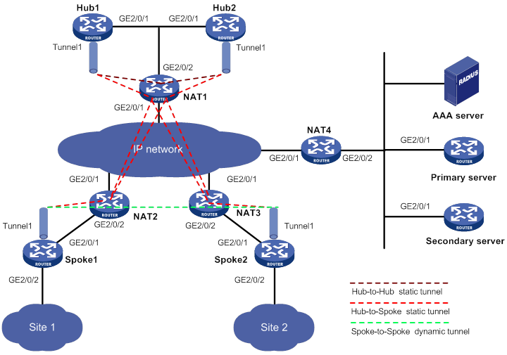
Table 18 Interface and IP address assignment
|
Device |
Interface |
IP address |
Device |
Interface |
IP address |
|
Hub 1 |
GE2/0/1 |
10.0.0.2/24 |
Spoke 1 |
GE2/0/1 |
10.0.0.2/24 |
|
|
Tunnel1 |
192.168.0.1/24 |
|
GE2/0/2 |
192.168.1.1/24 |
|
Hub 2 |
GE2/0/1 |
10.0.0.3/24 |
|
Tunnel1 |
192.168.0.3/24 |
|
|
Tunnel1 |
192.168.0.2/24 |
Spoke 2 |
GE2/0/1 |
10.0.0.2/24 |
|
NAT1 |
GE2/0/1 |
1.0.0.1/24 |
|
GE2/0/2 |
192.168.2.1/24 |
|
|
GE2/0/2 |
10.0.0.1/24 |
|
Tunnel1 |
192.168.0.4/24 |
|
NAT2 |
GE2/0/1 |
1.0.0.2/24 |
NAT4 |
GE2/0/1 |
1.0.0.4/24 |
|
|
GE2/0/2 |
10.0.0.1/24 |
|
GE2/0/2 |
10.0.0.1/24 |
|
NAT3 |
GE2/0/1 |
1.0.0.3/24 |
AAA server |
|
10.0.0.2/24 |
|
|
GE2/0/2 |
10.0.0.1/24 |
Primary server |
GE2/0/1 |
10.0.0.3/24 |
|
|
|
|
Secondary server |
GE2/0/1 |
10.0.0.4/24 |
Configuring the primary VAM server
1. Configure IP addresses for the interfaces. (Details not shown.)
2. Configure AAA:
# Configure RADIUS scheme abc.
<PrimaryServer> system-view
[PrimaryServer] radius scheme abc
[PrimaryServer-radius-abc] primary authentication 1.0.0.10 1812
[PrimaryServer-radius-abc] primary accounting 1.0.0.10 1813
[PrimaryServer-radius-abc] key authentication simple 123
[PrimaryServer-radius-abc] key accounting simple 123
[PrimaryServer-radius-abc] user-name-format without-domain
[PrimaryServer-radius-abc] quit
[PrimaryServer] radius session-control enable
# Configure AAA methods for ISP domain abc.
[PrimaryServer] domain abc
[PrimaryServer-isp-abc] authentication advpn radius-scheme abc
[PrimaryServer-isp-abc] accounting advpn radius-scheme abc
[PrimaryServer-isp-abc] quit
[PrimaryServer] domain default enable abc
3. Configure the VAM server:
# Create ADVPN domain abc.
[PrimaryServer] vam server advpn-domain abc id 1
# Create hub group 0.
[PrimaryServer-vam-server-domain-abc] hub-group 0
# Configure hubs in hub group 0:
? Hub1—The private address is 192.168.0.1, the public address is 1.0.0.1 (after NAT), and the source port number of ADVPN packets is 4001 (after NAT).
? Hub2—The private address is 192.168.0.2, the public address is 1.0.0.1 (after NAT), and the source port number of ADVPN packets is 4002 (after NAT).
[PrimaryServer-vam-server-domain-abc-hub-group-0] hub private-address 192.168.0.1 public-address 1.0.0.1 advpn-port 4001
[PrimaryServer-vam-server-domain-abc-hub-group-0] hub private-address 192.168.0.2 public-address 1.0.0.1 advpn-port 4002
# Specify a spoke private IPv4 network.
[PrimaryServer-vam-server-domain-abc-hub-group-0] spoke private-address network 192.168.0.0 255.255.255.0
[PrimaryServer-vam-server-domain-abc-hub-group-0] quit
# Set the preshared key to 123456.
[PrimaryServer-vam-server-domain-abc] pre-shared-key simple 123456
# Set the authentication mode to CHAP.
[PrimaryServer-vam-server-domain-abc] authentication-method chap
# Set the keepalive interval to 10 seconds and the maximum number of keepalive retries to 3.
[PrimaryServer-vam-server-domain-abc] keepalive interval 10 retry 3
# Enable the VAM server for the ADVPN domain.
[PrimaryServer-vam-server-domain-abc] server enable
[PrimaryServer-vam-server-domain-abc] quit
# Configure a default route.
[PrimaryServer] ip route-static 0.0.0.0 0 10.0.0.1
Configuring the secondary VAM server
# Configure the secondary VAM server in the same way that the primary server is configured. (Details not shown.)
Configuring Hub 1
1. Configure IP addresses for the interfaces. (Details not shown.)
2. Configure the VAM client:
# Create VAM client Hub1.
<Hub1> system-view
[Hub1] vam client name Hub1
# Specify ADVPN domain abc for the VAM client.
[Hub1-vam-client-Hub1] advpn-domain abc
# Set the preshared key to 123456.
[Hub1-vam-client-Hub1] pre-shared-key simple 123456
# Set both the username and password to hub1.
[Hub1-vam-client-Hub1] user hub1 password simple hub1
# Specify the primary VAM server IP address as 1.0.0.4 (after NAT) and the port number as 4001 (after NAT).
[Hub1-vam-client-Hub1] server primary ip-address 1.0.0.4 port 4001
# Specify the secondary VAM server IP address as 1.0.0.4 (after NAT) and the port number as 4002 (after NAT).
[Hub1-vam-client-Hub1] server secondary ip-address 1.0.0.4 port 4002
# Enable the VAM client.
[Hub1-vam-client-Hub1] client enable
[Hub1-vam-client-Hub1] quit
3. Configure OSPF:
# Configure OSPF to advertise the private network.
[Hub1] ospf 1
[Hub1-ospf-1] area 0
[Hub1-ospf-1-area-0.0.0.0] network 192.168.0.0 0.0.0.255
[Hub1-ospf-1-area-0.0.0.0] quit
[Hub1-ospf-1] quit
# Configure a default route.
[Hub1] ip route-static 0.0.0.0 0 10.0.0.1
4. Configure UDP-mode IPv4 ADVPN tunnel interface tunnel1.
[Hub1] interface tunnel 1 mode advpn udp
[Hub1-Tunnel1] ip address 192.168.0.1 255.255.255.0
[Hub1-Tunnel1] vam client Hub1
[Hub1-Tunnel1] ospf network-type broadcast
[Hub1-Tunnel1] source gigabitethernet 2/0/1
[Hub1-Tunnel1] quit
Configuring Hub 2
1. Configure IP addresses for the interfaces. (Details not shown.)
2. Configure the VAM client:
# Create VAM client Hub2.
<Hub2> system-view
[Hub2] vam client name Hub2
# Specify ADVPN domain abc for the VAM client.
[Hub2-vam-client-Hub2] advpn-domain abc
# Set the preshared key to 123456.
[Hub2-vam-client-Hub2] pre-shared-key simple 123456
# Set both the username and password to hub2.
[Hub2-vam-client-Hub2] user hub2 password simple hub2
# Specify the primary and secondary VAM servers.
[Hub2-vam-client-Hub2] server primary ip-address 1.0.0.4 port 4001
[Hub2-vam-client-Hub2] server secondary ip-address 1.0.0.4 port 4002
# Enable the VAM client.
[Hub2-vam-client-Hub2] client enable
[Hub2-vam-client-Hub2] quit
3. Configure OSPF:
# Configure OSPF to advertise the private network.
[Hub1] ospf 1
[Hub1-ospf-1] area 0
[Hub1-ospf-1-area-0.0.0.0] network 192.168.0.0 0.0.0.255
[Hub1-ospf-1-area-0.0.0.0] quit
[Hub1-ospf-1] quit
# Configure a default route.
[Hub1] ip route-static 0.0.0.0 0 10.0.0.1
4. Configure UDP-mode IPv4 ADVPN tunnel interface tunnel1.
[Hub2] interface tunnel1 mode advpn udp
[Hub2-Tunnel1] ip address 192.168.0.2 255.255.255.0
[Hub2-Tunnel1] vam client Hub2
[Hub2-Tunnel1] ospf network-type broadcast
[Hub2-Tunnel1] source gigabitethernet 2/0/1
[Hub2-Tunnel1] quit
Configuring Spoke 1
1. Configure IP addresses for the interfaces. (Details not shown.)
2. Configure the VAM client:
# Create VAM client Spoke1.
<Spoke1> system-view
[Spoke1] vam client name Spoke1
# Specify ADVPN domain abc for the VAM client.
[Spoke1-vam-client-Spoke1] advpn-domain abc
# Set the preshared key to 123456.
[Spoke1-vam-client-Spoke1] pre-shared-key simple 123456
# Set both the username and password to spoke1.
[Spoke1-vam-client-Spoke1] user spoke1 password simple spoke1
# Specify the primary and secondary VAM servers.
[Spoke1-vam-client-Spoke1] server primary ip-address 1.0.0.4 port 4001
[Spoke1-vam-client-Spoke1] server secondary ip-address 1.0.0.4 port 4002
# Enable the VAM client.
[Spoke1-vam-client-Spoke1] client enable
[Spoke1-vam-client-Spoke1] quit
3. Configure OSPF:
# Configure OSPF to advertise the private network.
[Spoke1] ospf 1
[Spoke1-ospf-1] area 0
[Spoke1-ospf-1-area-0.0.0.0] network 192.168.0.0 0.0.0.255
[Spoke1-ospf-1-area-0.0.0.0] quit
[Spoke1-ospf-1] quit
# Configure a default route.
[Spoke1] ip route-static 0.0.0.0 0 10.0.0.1
4. Configure UDP-mode IPv4 ADVPN tunnel interface tunnel1. Configure its DR priority as 0 so Spoke 1 will not participate in DR/BDR election.
[Spoke1] interface tunnel1 mode advpn udp
[Spoke1-Tunnel1] ip address 192.168.0.3 255.255.255.0
[Spoke1-Tunnel1] vam client Spoke1
[Spoke1-Tunnel1] ospf network-type broadcast
[Spoke1-Tunnel1] ospf dr-priority 0
[Spoke1-Tunnel1] source gigabitethernet 2/0/1
[Spoke1-Tunnel1] quit
Configuring Spoke 2
1. Configure IP addresses for the interfaces. (Details not shown.)
2. Configure the VAM client:
# Create VAM client Spoke2.
<Spoke2> system-view
[Spoke2] vam client name Spoke2
# Specify ADVPN domain abc for the VAM client.
[Spoke2-vam-client-Spoke2] advpn-domain abc
# Set the preshared key to 123456.
[Spoke2-vam-client-Spoke2] pre-shared-key simple 123456
# Set both the username and password to spoke2.
[Spoke2-vam-client-Spoke2] user spoke2 password simple spoke2
# Specify the primary and secondary VAM servers.
[Spoke2-vam-client-Spoke2] server primary ip-address 1.0.0.4 port 4001
[Spoke2-vam-client-Spoke2] server secondary ip-address 1.0.0.4 port 4002
# Enable the VAM client.
[Spoke2-vam-client-Spoke2] client enable
[Spoke2-vam-client-Spoke2] quit
3. Configure OSPF:
# Configure OSPF to advertise the private network.
[Spoke2] ospf 1
[Spoke2-ospf-1] area 0
[Spoke2-ospf-1-area-0.0.0.0] network 192.168.0.0 0.0.0.255
[Spoke2-ospf-1-area-0.0.0.0] quit
[Spoke2-ospf-1] quit
# Configure a default route.
[Hub1] ip route-static 0.0.0.0 0 10.0.0.1
4. Configure UDP-mode IPv4 ADVPN tunnel interface tunnel1. Configure its DR priority as 0 so Spoke 2 will not participate in DR/BDR election.
[Spoke2] interface tunnel1 mode advpn udp
[Spoke2-Tunnel1] ip address 192.168.0.4 255.255.255.0
[Spoke2-Tunnel1] vam client Spoke2
[Spoke2-Tunnel1] ospf network-type broadcast
[Spoke2-Tunnel1] ospf dr-priority 0
[Spoke2-Tunnel1] source gigabitethernet 2/0/1
[Spoke2-Tunnel1] quit
Configuring NAT 1
1. Configure IP addresses for the interfaces. (Details not shown.)
2. Configure NAT internal servers:
# Configure ACL 2000 to permit packets sourced from 10.0.0.0/24.
<NAT1> system-view
[NAT1] acl basic 2000
[NAT1-acl-basic-2000] rule permit source 10.0.0.0 0.0.0.255
[NAT1-acl-basic-2000] quit
# Configure NAT internal servers on GigabitEthernet 2/0/1:
? Allow external ADVPN nodes to access Hub 1 and Hub 2 by using the public address 1.0.0.1.
? Specify the source UDP port number as 18001 for both Hub 1 and Hub 2.
? Specify the UDP port number after NAT as 4001 for Hub 1, and as 4002 for Hub 2.
[NAT1] interface gigabitethernet 2/0/1
[NAT1-GigabitEthernet2/0/1] nat server protocol udp global current-interface 4001 inside 10.0.0.2 18001
[NAT1-GigabitEthernet2/0/1] nat server protocol udp global current-interface 4002 inside 10.0.0.3 18001
[NAT1-GigabitEthernet2/0/1] nat outbound 2000
[NAT1-GigabitEthernet2/0/1] quit
# Enable NAT hairpin on GigabitEthernet 2/0/2.
[NAT1] interface gigabitethernet 2/0/2
[NAT1-GigabitEthernet2/0/2] nat hairpin enable
[NAT1-GigabitEthernet2/0/2] quit
Configuring NAT 2
1. Configure IP addresses for the interfaces. (Details not shown.)
2. Configure NAT internal servers:
# Configure ACL 2000 to permit packets sourced from 10.0.0.0/24.
<NAT2> system-view
[NAT2] acl basic 2000
[NAT2-acl-basic-2000] rule permit source 10.0.0.0 0.0.0.255
[NAT2-acl-basic-2000] quit
# Create address group 1.
[NAT2] nat address-group 1
# Add address 1.0.0.2 into the group.
[NAT2-nat-address-group-1] address 1.0.0.2 1.0.0.2
[NAT2-nat-address-group-1] quit
# Configure NAT on GigabitEthernet 2/0/1.
[NAT2] interface gigabitethernet 2/0/1
[NAT2-GigabitEthernet2/0/1] nat outbound 2000 address-group 1
[NAT2-GigabitEthernet2/0/1] quit
# Configure EIM for PAT to translate the source address and source port of packets matching ACL 2000 from the same address and port to the same source public address and port.
[NAT2] nat mapping-behavior endpoint-independent acl 2000
Configuring NAT 3
# Configure NAT 3 in the same way that NAT 2 is configured. (Details not shown.)
Configuring NAT 4
1. Configure IP addresses for the interfaces. (Details not shown.)
2. Configure NAT internal servers on GigabitEthernet 2/0/1:
? Allow external VAM clients to access VAM and AAA servers by using the public address 1.0.0.4.
? Specify the source UDP port number as 18000 for both the primary and secondary VAM servers.
? Specify the UDP port number after NAT as 4001 for the primary server, and as 4002 for the secondary server.
<NAT4> system-view
[NAT4] interface gigabitethernet 2/0/1
[NAT4-GigabitEthernet2/0/1] nat server protocol udp global current-interface 4001 inside 10.0.0.3 18000
[NAT4-GigabitEthernet2/0/1] nat server protocol udp global current-interface 4002 inside 10.0.0.4 18000
Verifying the configuration
# Display IPv4 address mapping information for all VAM clients registered with the primary VAM server.
[PrimaryServer] display vam server address-map
ADVPN domain name: abc
Total private address mappings: 4
Group Private address Public address Type NAT Holding time
0 192.168.0.1 1.0.0.1 Hub Yes 0H 52M 7S
0 192.168.0.2 1.0.0.1 Hub Yes 0H 47M 31S
0 192.168.0.3 1.0.0.2 Spoke Yes 0H 28M 25S
0 192.168.0.4 1.0.0.3 Spoke Yes 0H 19M 15S
# Display IPv4 address mapping information for all VAM clients registered with the secondary VAM server.
[SecondaryServer] display vam server address-map
ADVPN domain name: abc
Total private address mappings: 4
Group Private address Public address Type NAT Holding time
0 192.168.0.1 1.0.0.1 Hub Yes 0H 52M 7S
0 192.168.0.2 1.0.0.1 Hub Yes 0H 47M 31S
0 192.168.0.3 1.0.0.2 Spoke Yes 0H 28M 25S
0 192.168.0.4 1.0.0.3 Spoke Yes 0H 19M 15S
The output shows that Hub 1, Hub 2, Spoke 1, Spoke 2, and Spoke 3 all have registered their address mapping information with the VAM servers.
# Display IPv4 ADVPN tunnel information on Hubs. This example uses Hub 1.
[Hub1] display advpn session
Interface : Tunnel1
Number of sessions: 3
Private address Public address Port Type State Holding time
192.168.0.2 1.0.0.1 4002 H-H Success 0H 46M 8S
192.168.0.3 1.0.0.2 2001 H-S Success 0H 27M 27S
192.168.0.4 1.0.0.3 2001 H-S Success 0H 18M 18S
The output shows that Hub 1 has established a permanent tunnel to Hub 2, Spoke 1, and Spoke 2.
# Display IPv4 ADVPN tunnel information on Spokes. This example uses Spoke 1.
[Spoke1] display advpn session
Interface : Tunnel1
Number of sessions: 2
Private address Public address Port Type State Holding time
192.168.0.1 1.0.0.1 4001 S-H Success 0H 46M 8S
192.168.0.2 1.0.0.1 4002 S-H Success 0H 46M 8S
The output shows that Spoke 1 has established a permanent hub-spoke tunnel to Hub 1 and Hub 2.
# Verify that Spoke 1 can ping the private address 192.168.0.4 of Spoke 2.
[Spoke1] ping 192.168.0.4
Ping 192.168.0.4 (192.168.0.4): 56 data bytes, press CTRL_C to break
56 bytes from 192.168.0.4: icmp_seq=0 ttl=255 time=4.000 ms
56 bytes from 192.168.0.4: icmp_seq=1 ttl=255 time=0.000 ms
56 bytes from 192.168.0.4: icmp_seq=2 ttl=255 time=0.000 ms
56 bytes from 192.168.0.4: icmp_seq=3 ttl=255 time=0.000 ms
56 bytes from 192.168.0.4: icmp_seq=4 ttl=255 time=1.000 ms
--- Ping statistics for 192.168.0.4 ---
5 packets transmitted, 5 packets received, 0.0% packet loss
round-trip min/avg/max/std-dev = 0.000/1.000/4.000/1.549 ms
# Display IPv4 ADVPN tunnel information on Spokes. This example uses Spoke 1.
[Spoke1] display advpn session
Interface : Tunnel1
Number of sessions: 3
Private address Public address Port Type State Holding time
192.168.0.1 1.0.0.1 4001 S-H Success 0H 46M 8S
192.168.0.2 1.0.0.1 4002 S-H Success 0H 46M 8S
192.168.0.4 1.0.0.3 2001 S-S Success 0H 0M 1S
The output shows the following information:
· Spoke 1 has established a permanent hub-spoke tunnel to Hub 1 and Hub 2.
· Spoke 1 has established a temporary spoke-spoke tunnel to Spoke 2.
Configuring AFT
Overview
Address Family Translation (AFT) translates an IP address of one address family into an IP address of the other address family. It enables an IPv4 network and an IPv6 network to communicate with each other, as shown in Figure 162. The IPv4 host and the IPv6 host can communicate with each other without changing the existing configuration.
Figure 162 AFT application scenario
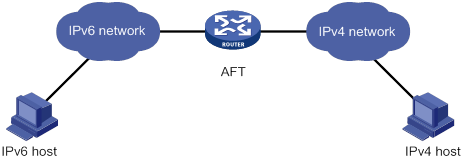
Compatibility information
Feature and hardware compatibility
|
Hardware |
AFT compatibility |
|
MSR810/810-W/810-W-DB/810-LM/810-W-LM/810-10-PoE/810-LM-HK/810-W-LM-HK/810-LMS/810-LUS |
Yes |
|
MSR2600-6-X1/2600-10-X1 |
Yes |
|
MSR 2630 |
Yes |
|
MSR3600-28/3600-51 |
Yes |
|
MSR3600-28-SI/3600-51-SI |
No |
|
MSR3610-X1/3610-X1-DP/3610-X1-DC/3610-X1-DP-DC |
Yes |
|
MSR 3610/3620/3620-DP/3640/3660 |
Yes |
|
MSR 5620/5660/5680 |
Yes |
|
Hardware |
AFT compatibility |
|
MSR810-LM-GL |
Yes |
|
MSR810-W-LM-GL |
Yes |
|
MSR830-6EI-GL |
Yes |
|
MSR830-10EI-GL |
Yes |
|
MSR830-6HI-GL |
Yes |
|
MSR830-10HI-GL |
Yes |
|
MSR2600-6-X1-GL |
Yes |
|
MSR3600-28-SI-GL |
No |
Command and hardware compatibility
Commands and descriptions for centralized devices apply to the following routers:
· MSR810/810-W/810-W-DB/810-LM/810-W-LM/810-10-PoE/810-LM-HK/810-W-LM-HK/810-LMS/810-LUS.
· MSR2600-6-X1/2600-10-X1.
· MSR 2630.
· MSR3600-28/3600-51.
· MSR3600-28-SI/3600-51-SI.
· MSR3610-X1/3610-X1-DP/3610-X1-DC/3610-X1-DP-DC.
· MSR 3610/3620/3620-DP/3640/3660.
· MSR810-LM-GL/810-W-LM-GL/830-6EI-GL/830-10EI-GL/830-6HI-GL/830-10HI-GL/2600-6-X1-GL/3600-28-SI-GL.
Commands and descriptions for distributed devices apply to the following routers:
· MSR5620.
· MSR 5660.
· MSR 5680.
AFT implementations
Static AFT
Static AFT creates a fixed mapping between an IPv4 address and an IPv6 address.
Dynamic AFT
Dynamic AFT creates a dynamic mapping between an IPv4 address and an IPv6 address.
When dynamic AFT performs IPv6-to-IPv4 source address translation, the Not Port Address Translation (NO-PAT) and Port Address Translation (PAT) modes are available.
NO-PAT
NO-PAT translates one IPv6 address to one IPv4 address. An IPv4 address assigned to one IPv6 host cannot be used by any other IPv6 host until it is released.
NO-PAT supports all IP packets.
PAT
PAT translates multiple IPv6 addresses to a single IPv4 address by mapping each IPv6 address and port to the IPv4 address and a unique port. PAT supports the following packet types:
· TCP packets.
· UDP packets.
· ICMPv6 echo request and echo reply messages.
PAT supports port blocks for connection limit and user tracing. Port blocks are generated by dividing the port range (1024 to 65535) by the port block size. Port block based PAT maps multiple IPv6 addresses to one IPv4 address and uses a port block for each IPv6 address.
Port block based PAT functions as follows:
1. When an IPv6 host first initiates a connection to the IPv4 network, it creates a mapping from the host's IPv6 address to an IPv4 address and a port block.
2. It translates the IPv6 address to the IPv4 address, and the source ports to ports in the port block for subsequent connections from the IPv6 host until the ports in the port block are exhausted.
|
|
NOTE: If the port range cannot be divided by the port block size exactly, the remaining ports are not used for translation. |
Prefix translation
NAT64 prefix translation
NAT64 prefix is an IPv6 address prefix used to construct an IPv6 address representing an IPv4 node in an IPv6 network. The IPv6 hosts do not use a constructed IPv6 address as their real IP address. The length of a NAT64 prefix can be 32, 40, 48, 56, 64, or 96.
As shown in Figure 163, the construction methods vary depending on the NAT64 prefix length. Bits 64 through 71 in the constructed IPv6 address are reserved bits and must always be zero.
· If the prefix length is 32, 64, or 96 bits, the IPv4 address contained in the IPv6 address will be integral.
· If the prefix length is 40, 48, or 56 bits, the IPv4 address contained in the IPv6 address will be divided into two parts by bits 64 through 71.
Figure 163 IPv6 address construction with NAT 64 prefix and IPv4 address
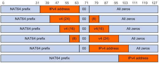
AFT uses a NAT64 prefix to perform the following translation:
· IPv4-to-IPv6 source address translation. AFT translates a source IPv4 address to an IPv6 address that is created by using the NAT64 prefix and the IPv4 address.
· IPv6-to-IPv4 destination address translation. AFT uses the NAT64 prefix to match destination IPv6 addresses and extracts the embedded IPv4 address from matching IPv6 addresses.
A NAT64 prefix cannot be on the same subnet as any interface on the device.
IVI prefix translation
An IVI prefix is a 32-bit IPv6 address prefix. An IVI address is the IPv6 address that an IPv6 node uses. As shown in Figure 164, the IVI address includes an IVI prefix and an IPv4 address.
![]()
AFT uses an IVI prefix for IPv6-to-IPv4 source address translation. If a source IPv6 address matches the IVI prefix, AFT translates it to the embedded IPv4 address.
General prefix translation
A general prefix is an IPv6 address prefix used to construct an IPv6 address representing an IPv4 node in an IPv6 network. The length of a general prefix can be 32, 40, 48, 56, 64, or 96.
As shown in Figure 165, a general prefix based IPv6 address does not have reserved bits, and an IPv4 address is embedded as a whole into an IPv6 address.
Figure 165 General prefix based IPv6 address format
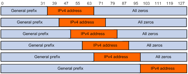
AFT uses a general prefix for IPv6-to-IPv4 source and destination address translation. If a source or destination IPv6 address matches the general prefix, AFT translates it to the embedded IPv4 address.
A general prefix cannot be on the same subnet as any interface on the device.
AFT internal server
AFT internal server maps an IPv4 address and port number to the IPv6 address and port number of an IPv6 internal server. It allows the IPv6 internal server to provide services to IPv4 hosts.
AFT translation process
The address translation differs for IPv6-initiated communication and IPv4-initiated communication.
IPv6-initiated communication
As shown in Figure 166, when the IPv6 host initiates access to the IPv4 host, AFT operates as follows:
1. Upon receiving a packet from the IPv6 host, AFT compares the packet with IPv6-to-IPv4 destination address translation policies.
? If a matching policy is found, AFT translates the destination IPv6 address according to the policy.
? If no matching policy is found, AFT does not process the packet.
2. AFT performs pre-lookup to determine the output interface for the translated packet. PBR is not used for the pre-lookup.
? If a matching route is found, the process goes to step 3.
? If no matching route is found, AFT discards the packet.
3. AFT compares the source IPv6 address of the packet with IPv6-to-IPv4 source address translation policies.
? If a matching policy is found, AFT translates the source IPv6 address according to the policy.
? If no matching policy is found, AFT discards the packet.
4. AFT forwards the translated packet and records the mappings between IPv6 addresses and IPv4 addresses.
5. AFT translates the IPv4 addresses in the response packet header to IPv6 addresses based on the address mappings before packet forwarding.
For more information about IPv6-to-IPv4 destination address translation policies, see "Configuring an IPv6-to-IPv4 destination address translation policy."
For more information about IPv6-to-IPv4 source address translation policies, see "Configuring an IPv6-to-IPv4 source address translation policy."
Figure 166 AFT process for IPv6-initiated communication
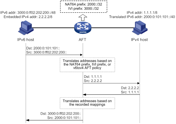
IPv4-initiated communication
As shown in Figure 167, when the IPv4 host initiates access to the IPv6 host, AFT operates as follows:
1. Upon receiving a packet from the IPv4 host, AFT compares the packet with IPv4-to-IPv6 destination address translation policies.
? If a matching policy is found, AFT translates the destination IPv4 address according to the policy.
? If no matching policy is found, AFT does not perform address translation.
2. AFT performs the pre-lookup to determine output interface for the translated packet. PBR is not used for the pre-lookup.
? If a matching route is found, the process goes to step 3.
? If no matching route is found, AFT discards the packet.
3. AFT compares the source IPv4 address with IPv4-to-IPv6 source address translation policies.
? If a matching policy is found, AFT translates the source IPv4 address according to the policy.
? If no matching policy is found, AFT discards the packet.
4. AFT forwards the translated packet and records the mappings between IPv4 addresses and IPv6 addresses.
5. AFT translates the IPv6 addresses in the response packet header to IPv4 addresses based on the address mappings before packet forwarding.
For more information about IPv4-to-IPv6 destination address translation policies, see "Configuring an IPv4-to-IPv6 destination address translation policy."
For more information about IPv4-to-IPv6 source address translation policies, see "Configuring an IPv4-to-IPv6 source address translation policy."
Figure 167 AFT process for IPv4-initiated communication
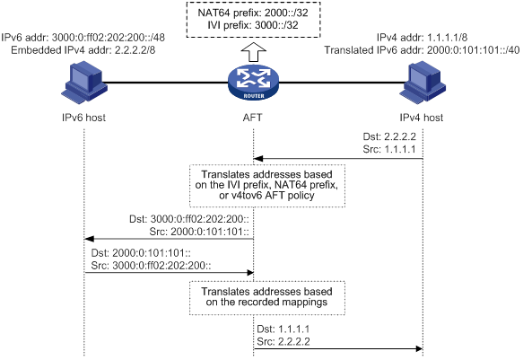
AFT configuration task list
IPv6-initiated communication
|
Task at a glance |
|
(Required.) Enabling AFT |
|
(Required.) Configuring an IPv6-to-IPv4 destination address translation policy |
|
(Required.) Configuring an IPv6-to-IPv4 source address translation policy |
|
(Optional.) Configuring AFT logging |
|
(Optional.) Setting the ToS field to 0 for translated IPv4 packets |
IPv4-initiated communication
|
Task at a glance |
|
(Required.) Enabling AFT |
|
(Required.) Configuring an IPv4-to-IPv6 destination address translation policy |
|
(Required.) Configuring an IPv4-to-IPv6 source address translation policy |
|
(Optional.) Configuring AFT logging |
|
(Optional.) Setting the Traffic Class field to 0 for translated IPv6 packets |
Enabling AFT
To implement address translation between IPv4 and IPv6 networks, you must enable AFT on interfaces connected to the IPv4 network and interfaces connected to the IPv6 network.
To enable AFT:
|
Step |
Command |
Remarks |
|
1. Enter system view. |
system-view |
N/A |
|
2. Enter interface view. |
interface interface-type interface-number |
N/A |
|
3. Enable AFT. |
aft enable |
By default, AFT is disabled. |
Configuring an IPv6-to-IPv4 destination address translation policy
AFT compares an IPv6 packet with IPv6-to-IPv4 destination address translation policies in the following order:
1. IPv4-to-IPv6 source address static mappings.
2. General prefixes.
3. NAT64 prefixes.
To configure an IPv6-to-IPv4 destination address translation policy:
|
Step |
Command |
Remarks |
|
1. Enter system view. |
system-view |
N/A |
|
2. Configure an IPv6-to-IPv4 destination address translation policy. |
·
Configure an IPv4-to-IPv6 source address
static mapping: ·
Configure a general prefix: ·
Configure a NAT64 prefix: |
By default, no IPv6-to-IPv4 destination address translation policies exist. |
Configuring an IPv6-to-IPv4 source address translation policy
AFT compares an IPv6 packet with IPv6-to-IPv4 source address translation policies in the following order:
1. IPv6-to-IPv4 source address static mappings.
2. General prefixes.
3. IVI prefixes.
4. IPv6-to-IPv4 source address dynamic translation policies.
To configure an IPv6-to-IPv4 source address translation policy:
|
Step |
Command |
Remarks |
|
1. Enter system view. |
system-view |
N/A |
|
2. Create an AFT address group and enter AFT address group view. |
aft address-group group-id |
By default, no AFT address groups exist. This step is required if you decide to use an address group in an IPv6-to-IPv4 source address dynamic translation policy. |
|
3. Add an address range to the address group. |
address start-address end-address |
By default, no address ranges exist. You can add multiple address ranges to an address group. The address ranges must not overlap. |
|
4. Return to system view. |
quit |
N/A |
|
5. Configure an IPv6-to-IPv4 source address translation policy. |
·
Configure an IPv6-to-IPv4 source address
static mapping: ·
Configure an IPv6-to-IPv4 source address
dynamic translation policy: ·
Configure a general prefix: ·
Configure an IVI prefix: |
By default, no IPv6-to-IPv4 source address translation policies exist. |
Configuring an IPv4-to-IPv6 destination address translation policy
AFT compares an IPv4 packet with IPv4-to-IPv6 destination address translation policies in the following order:
1. AFT mappings for IPv6 internal servers.
2. IPv6-to-IPv4 source address static mappings.
3. IPv4-to-IPv6 destination address dynamic translation policies.
To configure an IPv4-to-IPv6 destination address translation policy:
|
Step |
Command |
Remarks |
|
1. Enter system view. |
system-view |
N/A |
|
2. Configure an IPv4-to-IPv6 destination address translation policy. |
·
Configure an AFT mapping for an IPv6 internal
server: ·
Configure an IPv6-to-IPv4 source address
static mapping: ·
Configure an IPv4-to-IPv6 destination address
dynamic translation policy: |
By default, no IPv4-to-IPv6 destination address translation policies exist. You can use a nonexistent IVI prefix or general prefix in a policy, but the policy takes effect only after you configure the prefix. |
Configuring an IPv4-to-IPv6 source address translation policy
AFT compares an IPv4 packet with IPv4-to-IPv6 source address translation policies in the following order:
1. IPv4-to-IPv6 source address static mappings.
2. IPv4-to-IPv6 source address dynamic translation policies.
3. The first NAT64 prefix.
To configure an IPv4-to-IPv6 source address translation policy:
|
Step |
Command |
Remarks |
|
1. Enter system view. |
system-view |
N/A |
|
2. Configure an IPv4-to-IPv6 source address translation policy. |
·
Configure an IPv4-to-IPv6 source address static
mapping: ·
Configure an IPv4-to-IPv6 source address
dynamic translation policy: ·
Configure a NAT64 prefix: |
By default, no IPv4-to-IPv6 source address translation policies exist. You can use a nonexistent NAT64 prefix or general prefix in a policy, but the policy takes effect only after you configure the prefix. |
Configuring AFT logging
For security auditing, you can configure AFT logging to record AFT session information. AFT sessions refer to sessions whose source and destination addresses have been translated by AFT.
To configure AFT logging:
|
Step |
Command |
Remarks |
|
1. Enter system view. |
system-view |
N/A |
|
2. Enable AFT logging. |
aft log enable |
By default, AFT logging is disabled. |
|
3. Enable AFT session establishment logging. |
aft log flow-begin |
By default, AFT session establishment logging is disabled. |
|
4. Enable AFT session removal logging. |
aft log flow-end |
By default, AFT session removal logging is disabled. |
Setting the ToS field to 0 for translated IPv4 packets
|
Step |
Command |
Remarks |
|
1. Enter system view. |
system-view |
N/A |
|
2. Set the ToS field to 0 for IPv4 packets translated from IPv6 packets. |
aft turn-off tos |
By default, the ToS field value of translated IPv4 packets is the same as the Traffic Class field value of original IPv6 packets. |
Setting the Traffic Class field to 0 for translated IPv6 packets
|
Step |
Command |
Remarks |
|
1. Enter system view. |
system-view |
N/A |
|
2. Set the Traffic Class field to 0 for IPv6 packets translated from IPv4 packets. |
aft turn-off traffic-class |
By default, the Traffic Class field value of translated IPv6 packets is the same as the ToS field value of original IPv4 packets. |
Displaying and maintaining AFT
Execute display commands in any view and reset commands in user view.
|
Task |
Command |
|
Display AFT configuration. |
display aft configuration |
|
Display AFT address group information. |
display aft address-group [ group-id ] |
|
Display AFT mappings (centralized devices in standalone mode). |
display aft address-mapping |
|
Display AFT mappings (distributed devices in standalone mode/centralized devices in IRF mode). |
display aft address-mapping [ slot slot-number ] |
|
Display AFT mappings (distributed devices in IRF mode). |
display aft address-mapping [ chassis chassis-number slot slot-number ] |
|
Display information about AFT NO-PAT entries (centralized devices in standalone mode). |
display aft no-pat |
|
Display information about AFT NO-PAT entries (distributed devices in standalone mode/centralized devices in IRF mode). |
display aft no-pat [ slot slot-number ] |
|
Display information about AFT NO-PAT entries (distributed devices in IRF mode). |
display aft no-pat [ chassis chassis-number slot slot-number ] |
|
Display AFT port block mappings (centralized devices in standalone mode). |
display aft port-block |
|
Display AFT port block mappings (distributed devices in standalone mode/centralized devices in IRF mode). |
display aft port-block [ slot slot-number ] |
|
Display AFT port block mappings (distributed devices in IRF mode). |
display aft port-block [ chassis chassis-number slot slot-number ] |
|
Display information about AFT sessions (centralized devices in standalone mode). |
display aft session ipv4 [ { source-ip source-ip-address | destination-ip destination-ip-address } * [ vpn-instance ipv4-vpn-instance-name ] ] [ verbose ] display aft session ipv6 [ { source-ip source-ipv6-address | destination-ip destination-ipv6-address } * [ vpn-instance ipv6-vpn-instance-name ] ] [ verbose ] |
|
Display information about AFT sessions (distributed devices in standalone mode/centralized devices in IRF mode). |
display aft session ipv4 [ { source-ip source-ip-address | destination-ip destination-ip-address } * [ vpn-instance ipv4-vpn-instance-name ] ] [ slot slot-number [ cpu cpu-number ] ] [ verbose ] display aft session ipv6 [ { source-ip source-ipv6-address | destination-ip destination-ipv6-address } * [ vpn-instance ipv6-vpn-instance-name ] ] [ slot slot-number ] [ verbose ] |
|
Display information about AFT sessions (distributed devices in IRF mode). |
display aft session ipv4 [ { source-ip source-ip-address | destination-ip destination-ip-address } * [ vpn-instance ipv4-vpn –instance-name ] ] [ chassis chassis-number slot slot-number [ cpu cpu-number ] ] [ verbose ] display aft session ipv6 [ { source-ip source-ipv6-address | destination-ip destination-ipv6-address } * [ vpn-instance ipv6-vpn-instance-name ] ] [ chassis chassis-number slot slot-number ] [ verbose ] |
|
Display AFT statistics (centralized devices in standalone mode). |
display aft statistics |
|
Display AFT statistics (distributed devices in standalone mode/centralized devices in IRF mode). |
display aft statistics [ slot slot-number ] |
|
Display AFT statistics (distributed devices in IRF mode). |
display aft statistics [ chassis chassis-number slot slot-number ] |
|
Clear AFT sessions (centralized devices in standalone mode). |
|
|
Clear AFT sessions (distributed devices in standalone mode/centralized devices in IRF mode). |
reset aft session [ slot slot-number ] |
|
Clear AFT sessions (distributed devices in IRF mode). |
reset aft session [ chassis chassis-number slot slot-number ] |
|
Clear AFT statistics (centralized devices in standalone mode). |
reset aft statistics |
|
Clear AFT statistics (distributed devices in standalone mode/centralized devices in IRF mode). |
reset aft statistics [ slot slot-number ] |
|
Clear AFT statistics (distributed devices in IRF mode). |
reset aft statistics [ chassis chassis-number slot slot-number ] |
AFT configuration examples
Allowing IPv4 Internet access from an IPv6 network
Network requirements
As shown in Figure 168, a company upgrades the network to IPv6 and has IPv4 addresses from 10.1.1.1 to 10.1.1.3.
To allow IPv6 hosts on subnet 2013::/96 to access the IPv4 Internet, configure the following AFT policies on the router:
· Configure a NAT64 prefix to translate IPv4 addresses of IPv4 servers to IPv6 addresses.
· Configure an IPv6-to-IPv4 source address dynamic translation policy to translate source IPv6 addresses of IPv6-initiated packets to IPv4 addresses in the range of 10.1.1.1 to 10.1.1.3.
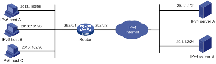
Configuration process
# Specify IP addresses for the interfaces on the router. (Details not shown.)
# Create AFT address group 0, and add the address range from 10.1.1.1 to 10.1.1.3 to the group.
<Router> system-view
[Router] aft address-group 0
[Router-aft-address-group-0] address 10.1.1.1 10.1.1.3
[Router-aft-address-group-0] quit
# Configure IPv6 ACL 2000 to permit IPv6 packets only from subnet 2013::/96 to pass through.
[Router] acl ipv6 basic 2000
[Router-acl-ipv6-basic-2000] rule permit source 2013:: 96
[Router-acl-ipv6-basic-2000] rule deny
[Router-acl-ipv6-basic-2000] quit
# Configure the router to translate source IPv6 addresses of packets permitted by IPv6 ACL 2000 to IPv4 addresses in address group 0.
[Router] aft v6tov4 source acl ipv6 number 2000 address-group 0
# Configure the router to use NAT64 prefix 2012::/96 to translate destination IPv6 addresses of IPv6 packets.
[Router] aft prefix-nat64 2012:: 96
# Enable AFT on GigabitEthernet 2/0/1, which is connected to the IPv6 network.
[Router] interface gigabitethernet 2/0/1
[Router-GigabitEthernet2/0/1] aft enable
[Router-GigabitEthernet2/0/1] quit
# Enable AFT on GigabitEthernet 2/0/2, which is connected to the IPv4 Internet.
[Router] interface gigabitethernet 2/0/2
[Router-GigabitEthernet2/0/2] aft enable
[Router-GigabitEthernet2/0/2] quit
Verifying the configuration
# Verify the connectivity between IPv6 hosts and IPv4 servers. This example pings IPv4 server A from IPv6 host A.
D:\>ping 2012::20.1.1.1
Pinging 2012::20.1.1.1 with 32 bytes of data:
Reply from 2012::20.1.1.1: time=3ms
Reply from 2012::20.1.1.1: time=3ms
Reply from 2012::20.1.1.1: time=3ms
Reply from 2012::20.1.1.1: time=3ms
# Display detailed information about IPv6 AFT sessions on the router.
[Router] display aft session ipv6 verbose
Initiator:
Source IP/port: 2013::100/0
Destination IP/port: 2012::1401:0101/32768
VPN instance/VLAN ID/Inline ID: -/-/-
Protocol: IPV6-ICMP(58)
Inbound interface: GigabitEthernet2/0/1
Responder:
Source IP/port: 2012::1401:0101/0
Destination IP/port: 2013::100/33024
VPN instance/VLAN ID/Inline ID: -/-/-
Protocol: IPV6-ICMP(58)
Inbound interface: GigabitEthernet2/0/2
State: ICMPV6_REPLY
Application: ICMP
Total sessions found: 1
# Display detailed information about IPv4 AFT sessions on the router.
[Router] display aft session ipv4 verbose
Initiator:
Source IP/port: 10.1.1.1/1025
Destination IP/port: 20.1.1.1/2048
DS-Lite tunnel peer: -
VPN instance/VLAN ID/Inline ID: -/-/-
Protocol: ICMP(1)
Inbound interface: GigabitEthernet2/0/1
Responder:
Source IP/port: 20.1.1.1/1025
Destination IP/port: 10.1.1.1/0
DS-Lite tunnel peer: -
VPN instance/VLAN ID/Inline ID: -/-/-
Protocol: ICMP(1)
Inbound interface: GigabitEthernet2/0/2
State: ICMP_REPLY
Application: ICMP
Total sessions found: 1
Providing FTP service from an IPv6 network to the IPv4 Internet
Network requirements
As shown in Figure 169, a company upgrades the network to IPv6, and it has an IPv4 address 10.1.1.1.
To allow the IPv6 FTP server to provide FTP services to IPv4 hosts, configure the following AFT policies on the router:
· Map the IPv6 FTP server's IPv6 address and TCP port number to the company's IPv4 address and TCP port number.
· Configure a NAT64 prefix to translate source IPv4 addresses of IPv4 packets to source IPv6 addresses.
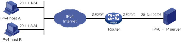
Configuration procedure
# Specify IP addresses for the interfaces on the router. (Details not shown.)
# Map IPv4 address 10.1.1.1 with TCP port 21 to IPv6 address 2013::102 with TCP port 21 for the IPv6 internal FTP server.
<Router> system-view
[Router] aft v6server protocol tcp 10.1.1.1 21 2013::102 21
# Configure the router to use NAT64 prefix 2012:: 96 to translate source addresses of IPv4 packets.
[Router] aft prefix-nat64 2012:: 96
# Enable AFT on GigabitEthernet 2/0/1, which is connected to the IPv4 Internet.
[Router] interface gigabitethernet 2/0/1
[Router-GigabitEthernet2/0/1] aft enable
[Router-GigabitEthernet2/0/1] quit
# Enable AFT on GigabitEthernet 2/0/2, which is connected to the IPv6 FTP server.
[Router] interface gigabitethernet 2/0/2
[Router-GigabitEthernet2/0/2] aft enable
[Router-GigabitEthernet2/0/2] quit
Verifying the configuration
# Verify that IPv4 hosts can use FTP to access the IPv6 FTP server. (Details not shown.)
# Display detailed information about IPv6 AFT sessions on the router.
[Router] display aft session ipv4 verbose
Initiator:
Source IP/port: 20.1.1.1/11025
Destination IP/port: 10.1.1.1/21
DS-Lite tunnel peer: -
VPN instance/VLAN ID/Inline ID: -/-/-
Protocol: TCP(6)
Inbound interface: GigabitEthernet2/0/1
Responder:
Source IP/port: 10.1.1.1/21
Destination IP/port: 20.1.1.1/11025
DS-Lite tunnel peer: -
VPN instance/VLAN ID/Inline ID: -/-/-
Protocol: TCP(6)
Inbound interface: GigabitEthernet2/0/2
State: TCP_ESTABLISHED
Application: FTP
Total sessions found: 1
# Display detailed information about IPv4 AFT sessions on the router.
[Router] display aft session ipv6 verbose
Initiator:
Source IP/port: 2012::1401:0101/1029
Destination IP/port: 2013::102/21
VPN instance/VLAN ID/Inline ID: -/-/-
Protocol: TCP(6)
Inbound interface: GigabitEthernet2/0/1
Responder:
Source IP/port: 2013::102/21
Destination IP/port: 2012::1401:0101/1029
VPN instance/VLAN ID/Inline ID: -/-/-
Protocol: TCP(6)
Inbound interface: GigabitEthernet2/0/2
State: TCP_ESTABLISHED
Application: FTP
Total sessions found: 1
Allowing mutual access between IPv4 and IPv6 networks
Network requirements
As shown in Figure 170, a company deploys both an IPv4 network and an IPv6 network.
To allow mutual access between the IPv4 network and the IPv6 network, configure the following AFT policies on the router:
· Assign an IVI prefix and an IPv4 subnet to the IPv6 network. Each IPv6 host uses the IPv6 addresses formed by the IVI prefix and an IPv4 address on the IPv4 subnet.
· Configure a NAT64 prefix to translate source IPv4 addresses of packets initiated by the IPv4 network to IPv6 addresses.
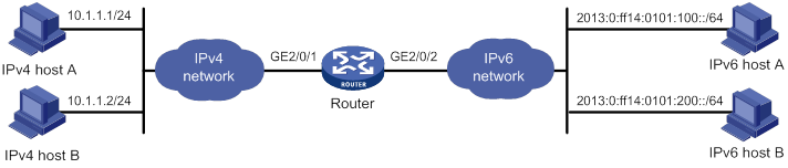
Configuration procedure
# Specify IP addresses for the interfaces on the router. The IPv6 addresses for IPv6 hosts are calculated by the IVI prefix 2013::/32 and IPv4 addresses in the range of 20.1.1.0/24. (Details not shown.)
# Configure IPv4 ACL 2000 to permits all IPv4 packets to pass through.
<Router> system-view
[Router] acl basic 2000
[Router-acl-ipv4-basic-2000] rule permit
[Router-acl-ipv4-basic-2000] quit
# Configure the router to use NAT64 prefix 2012:: 96 to translate source addresses of IPv4 packets. The router also uses the prefix to translate destination addresses of IPv6 packets.
[Router] aft prefix-nat64 2012:: 96
# Configure the router to use IVI prefix 2013:: to translate source addresses of IPv6 packets.
[Router] aft prefix-ivi 2013::
# Configure the router to use IVI prefix 2013:: to translate destination addresses of packets permitted by IPv4 ACL 2000.
[Router] aft v4tov6 destination acl number 2000 prefix-ivi 2013::
# Enable AFT on GigabitEthernet 2/0/1, which is connected to the IPv4 network.
[Router] interface gigabitethernet 2/0/1
[Router-GigabitEthernet2/0/1] aft enable
[Router-GigabitEthernet2/0/1] quit
# Enable AFT on GigabitEthernet 2/0/2, which is connected to the IPv6 network.
[Router] interface gigabitethernet 2/0/2
[Router-GigabitEthernet2/0/2] aft enable
[Router-GigabitEthernet2/0/2] quit
Verifying the configuration
# Verify the connectivity between IPv6 hosts and IPv4 hosts. This example pings IPv4 host A from IPv6 host A.
D:\>ping 2012::a01:0101
Pinging 2012::a01:0101 with 32 bytes of data:
Reply from 2012::a01:0101: time=3ms
Reply from 2012::a01:0101: time=3ms
Reply from 2012::a01:0101: time=3ms
Reply from 2012::a01:0101: time=3ms
# Display information about IPv6 AFT sessions on the router.
[Router] display aft session ipv6 verbose
Initiator:
Source IP/port: 2013:0:FF14:0101:0100::/0
Destination IP/port: 2012::0a01:0101/32768
VPN instance/VLAN ID/Inline ID: -/-/-
Protocol: IPV6-ICMP(58)
Inbound interface: GigabitEthernet2/0/2
Responder:
Source IP/port: 2012::0a01:0101/0
Destination IP/port: 2013:0:FF14:0101:0100::/33024
VPN instance/VLAN ID/Inline ID: -/-/-
Protocol: IPV6-ICMP(58)
Inbound interface: GigabitEthernet2/0/1
State: ICMPV6_REPLY
Application: ICMP
Total sessions found: 1
# Display information about IPv4 AFT sessions on the router.
[Router] display aft session ipv4 verbose
Initiator:
Source IP/port: 20.1.1.1/1025
Destination IP/port: 10.1.1.1/2048
DS-Lite tunnel peer: -
VPN instance/VLAN ID/Inline ID: -/-/-
Protocol: ICMP(1)
Inbound interface: GigabitEthernet2/0/2
Responder:
Source IP/port: 10.1.1.1/1025
Destination IP/port: 20.1.1.1/0
DS-Lite tunnel peer: -
VPN instance/VLAN ID/Inline ID: -/-/-
Protocol: ICMP(1)
Inbound interface: GigabitEthernet2/0/1
State: ICMP_REPLY
Application: ICMP
Total sessions found: 1
Allowing IPv6 Internet access from an IPv4 network
Network requirements
As shown in Figure 171, a company deploys an IPv4 network, and the Internet migrates to IPv6.
To allow IPv4 hosts to access the IPv6 server in the IPv6 Internet, configure the following AFT policies on the router:
· Configure an IPv4-to-IPv6 source address dynamic translation policy.
· Configure an IPv6-to-IPv4 source address static mapping for the IPv6 server.
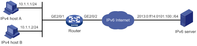
Configuration procedure
# Specify IP addresses for the interfaces on the router. (Details not shown.)
# Configure IPv4 ACL 2000 to permit IPv4 packets only from subnet 10.1.1.0/24 to pass through.
<Router> system-view
[Router] acl basic 2000
[Router-acl-ipv4-basic-2000] rule permit source 10.1.1.0 0.0.0.255
[Router-acl-ipv4-basic-2000] rule deny
[Router-acl-ipv4-basic-2000] quit
# Configure NAT64 prefix 2012:: 96.
[Router] aft prefix-nat64 2012:: 96
# Configure the router to use NAT64 prefix 2012:: 96 to translate source addresses of packets permitted by IPv4 ACL 2000.
[Router] aft v4tov6 source acl number 2000 prefix-nat64 2012:: 96
# Map source IPv6 address 2013:0:ff14:0101:100:: to source IPv4 address 20.1.1.1.
[Router] aft v6tov4 source 2013:0:ff14:0101:100:: 20.1.1.1
# Enable AFT on GigabitEthernet 2/0/1, which is connected to the IPv4 network.
[Router] interface gigabitethernet 2/0/1
[Router-GigabitEthernet2/0/1] aft enable
[Router-GigabitEthernet2/0/1] quit
# Enable AFT on GigabitEthernet 2/0/2, which is connected to the IPv6 Internet.
[Router] interface gigabitethernet 2/0/2
[Router-GigabitEthernet2/0/2] aft enable
[Router-GigabitEthernet2/0/2] quit
Verifying the configuration
# Verify the connectivity between the IPv4 hosts and the IPv6 server. This example uses the ping utility on an IPv4 host.
D:\>ping 20.1.1.1
Pinging 20.1.1.1 with 32 bytes of data:
Reply from 20.1.1.1: bytes=32 time=14ms TTL=63
Reply from 20.1.1.1: bytes=32 time=1ms TTL=63
Reply from 20.1.1.1: bytes=32 time=1ms TTL=63
Reply from 20.1.1.1: bytes=32 time=1ms TTL=63
# Display detailed information about IPv6 AFT sessions on the router.
[Router] display aft session ipv4 verbose
Initiator:
Source IP/port: 10.1.1.1/1025
Destination IP/port: 20.1.1.1/2048
DS-Lite tunnel peer: -
VPN instance/VLAN ID/Inline ID: -/-/-
Protocol: ICMP(1)
Inbound interface: GigabitEthernet2/0/1
Responder:
Source IP/port: 20.1.1.1/1025
Destination IP/port: 10.1.1.1/0
DS-Lite tunnel peer: -
VPN instance/VLAN ID/Inline ID: -/-/-
Protocol: ICMP(1)
Inbound interface: GigabitEthernet2/0/2
State: ICMP_REPLY
Application: ICMP
Total sessions found: 1
# Display detailed information about IPv4 AFT sessions on the router.
[Router] display aft session ipv6 verbose
Initiator:
Source IP/port: 2012::0A01:0101/0
Destination IP/port: 2013:0:FF14:0101:0100::/32768
VPN instance/VLAN ID/Inline ID: -/-/-
Protocol: IPV6-ICMP(58)
Inbound interface: GigabitEthernet2/0/1
Responder:
Source IP/port: 2013:0:FF14:0101:0100::/0
Destination IP/port: 2012::0A01:0101/33024
VPN instance/VLAN ID/Inline ID: -/-/-
Protocol: IPV6-ICMP(58)
Inbound interface: GigabitEthernet2/0/2
State: ICMPV6_REPLY
Application: ICMP
Total sessions found: 1
Providing FTP service from an IPv4 network to the IPv6 Internet
Network requirements
As shown in Figure 172, a company deploys an IPv4 network, and it has an IPv6 address 2012::1. The Internet migrates to IPv6.
To allow the IPv4 FTP server to provide FTP services to IPv6 hosts, configure the following AFT policies on the router:
· Configure an IPv4-to-IPv6 source address static mapping for the IPv4 FTP server. The router uses the mapping to translate the destination IPv6 address of IPv6-initiated addresses to the IPv4 address.
· Configure an IPv6-to-IPv4 source address dynamic translation policy. The router translates source IPv6 addresses of IPv6-initiated packets to source IPv4 addresses 30.1.1.1 and 30.1.1.2.
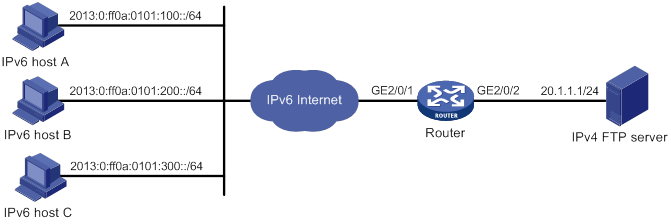
Configuration procedure
# Specify IP addresses for the interfaces on the router. (Details not shown.)
# Map source IPv4 address 20.1.1.1 to source IPv6 address 2012::1.
<Router> system-view
[Router] aft v4tov6 source 20.1.1.1 2012::1
# Configure address group 0, and add the address range from 30.1.1.1 to 30.1.1.2 to the group.
[Router] aft address-group 0
[Router-aft-address-group-0] address 30.1.1.1 30.1.1.2
[Router-aft-address-group-0] quit
# Configure IPv6 ACL 2000 to permit all IPv6 packets to pass through.
[Router] acl ipv6 basic 2000
[Router-acl-ipv6-basic-2000] rule permit
[Router-acl-ipv6-basic-2000] quit
# Configure the router to translate source addresses of IPv6 packets permitted by IPv6 ACL 2000 to IPv4 addresses in address group 0.
[Router] aft v6tov4 source acl ipv6 number 2000 address-group 0
# Enable AFT on GigabitEthernet 2/0/1, which is connected to the IPv6 Internet.
[Router] interface gigabitethernet 2/0/1
[Router-GigabitEthernet2/0/1] aft enable
[Router-GigabitEthernet2/0/1] quit
# Enable AFT on GigabitEthernet 2/0/2, which is connected to the IPv4 network.
[Router] interface gigabitethernet 2/0/2
[Router-GigabitEthernet2/0/2] aft enable
[Router-GigabitEthernet2/0/2] quit
Verifying the configuration
# Verify the connectivity between the IPv6 hosts and the IPv4 FTP server. For example, ping the IPv4 FTP server from IPv6 host A.
D:\>ping 2012::1
Pinging 2012::1 with 32 bytes of data:
Reply from 2012::1: time=3ms
Reply from 2012::1: time=3ms
Reply from 2012::1: time=3ms
Reply from 2012::1: time=3ms
# Display detailed information about IPv6 AFT sessions on the router.
[Router] display aft session ipv6 verbose
Initiator:
Source IP/port: 2013:0:FF0A:0101:0100::/1029
Destination IP/port: 2012::1/21
VPN instance/VLAN ID/Inline ID: -/-/-
Protocol: TCP(6)
Inbound interface: GigabitEthernet2/0/1
Responder:
Source IP/port: 2012::1/21
Destination IP/port: 2013:0:FF0A:0101:0100::/1029
VPN instance/VLAN ID/Inline ID: -/-/-
Protocol: TCP(6)
Inbound interface: GigabitEthernet2/0/2
State: TCP_ESTABLISHED
Application: FTP
Total sessions found: 1
# Display detailed information about IPv4 AFT sessions on the router.
[Router] display aft session ipv4 verbose
Initiator:
Source IP/port: 30.1.1.1/11025
Destination IP/port: 20.1.1.1/21
DS-Lite tunnel peer: -
VPN instance/VLAN ID/Inline ID: -/-/-
Protocol: TCP(6)
Inbound interface: GigabitEthernet2/0/1
Responder:
Source IP/port: 20.1.1.1/21
Destination IP/port: 30.1.1.1/11025
DS-Lite tunnel peer: -
VPN instance/VLAN ID/Inline ID: -/-/-
Protocol: TCP(6)
Inbound interface: GigabitEthernet2/0/2
State: TCP_ESTABLISHED
Application: FTP
Total sessions found: 1
Configuring WAAS
Overview
The Wide Area Application Services (WAAS) feature is a set of services that can optimize WAN traffic. WAAS solves WAN issues such as high delay and low bandwidth by using optimization services. WAAS provides the following optimization services:
· Transport Flow Optimization (TFO).
· Data Redundancy Elimination (DRE).
· Lempel-Ziv compression (LZ compression).
TFO
TFO optimizes TCP traffic without modifying packet header information. TFO uses the following optimization methods:
· Slow start optimization.
· Increased buffering.
· Congestion algorithm optimization.
· Selective acknowledgement.
Slow start optimization
The initial congestion window size for TCP slow start is one TCP segment. During slow start, TCP doubles the congestion window size for each received ACK that acknowledges new data. In this manner, the congestion window will reach an appropriate value by examining the congestion status. In a WAN environment, the congestion window takes a long time to reach an appropriate size because of high delay.
Slow start optimization shortens the slow start process by increasing the initial congestion window size.
Increased buffering
TCP has a maximum buffer size of 64 KB. After the sender sends 64 KB data, it must wait for an ACK from the receiver before continuing to send data. This mechanism wastes bandwidth on a WAN link.
Increased buffering increases the TCP buffer size to a maximum of 16384 KB. This improves link efficiency.
Congestion algorithm optimization
TCP uses the congestion window to control congestion. The window size indicates the size of data that can be sent out before an ACK is received. The window size changes with the congestion status. The greater the window size, the faster the data rate. A higher data rate more likely causes congestion. The smaller the window size, the lower the data rate. A lower data rate causes low link efficiency.
Congestion algorithm optimization achieves a trade-off between the data rate and congestion by selecting the optimum window size.
Selective acknowledgement
TCP uses a cumulative acknowledgement scheme. This scheme forces the sender to either wait a roundtrip time to know each lost packet, or to unnecessarily retransmit segments that have been correctly received. When multiple nonconsecutive segments are lost, this scheme reduces overall TCP throughput.
Selective acknowledgement (SACK) allows the receiver to inform the sender of all segments that have arrived successfully. The sender retransmits only the segments that have been lost.
DRE
DRE reduces the size of transmitted data by replacing repeated data blocks with shorter indexes. A WAAS device synchronizes its data dictionary to its peer devices. A data dictionary stores mappings between repeated data blocks and indexes.
Replacing repeated data blocks with indexes is called DRE compression. Replacing indexes with repeated data blocks is called DRE decompression.
DRE compression process
DRE compresses data in the following process:
1. The sending WAAS device caches TCP data and sends a large data block to the DRE module.
2. The DRE module divides the large data block into non-overlapping data blocks.
? For a repeated data block, the DRE module performs the following operations:
- Replaces the data block with its index and creates an MD5 digest for the data block.
- Sends the index and MD5 digest to the peer.
? For a non-repeated data block, the DRE module performs the following operations:
- Creates an index for the data block and adds it to the local data dictionary.
- Creates an MD5 digest for the data block and sends the data block, index, and MD5 digest to the peer.
To improve calculation speed and efficiency, DRE uses a sliding window mechanism to segment data and detect data redundancy. This mechanism detects repeated data blocks by using a fixed-size window to compare the original data byte by byte with data blocks in the dictionary.
DRE decompression process
DRE decompresses data in the following process:
1. The receiving WAAS device reconstructs the original data.
? For an index, the device replaces the index with its data block after querying the data dictionary.
If the query fails, the decompression fails, and the receiving WAAS device waits for the peer to retransmit the data.
? For an index and a data block, the device creates an entry for them and adds the entry to the local data dictionary.
2. The receiving WAAS device calculates an MD5 digest for the original data and compares the calculated MD5 digest with the MD5 digest in the packet.
? If the two MD5 digests are the same, the decompression succeeds.
? If the two MD5 digests are different, the decompression fails, and the receiving WAAS device waits for the peer to retransmit the data.
LZ compression
LZ compression is a lossless compression algorithm that uses a compression dictionary to replace repeated data in the same message. The compression dictionary is carried in the compression result. The sending device uses the sliding window technology to detect repeated data.
Compared with DRE, LZ compression has a lower compression ratio. LZ compression does not require synchronization of compression dictionaries between the local and peer devices. This reduces memory consumption.
Protocols and standards
· RFC 1323, TCP Extensions for High Performance
· RFC 3390, Increasing TCP's Initial Window
· RFC 2581, TCP Congestion Control
· RFC 2018, TCP Selective Acknowledgment Options
· RFC 3042, Enhancing TCP's Loss Recovery Using Limited Transmit
· RFC 2582, The NewReno Modification to TCP's Fast Recovery Algorithm
Compatibility information
Feature and hardware compatibility
The following matrix shows the feature and hardware compatibility:
|
Hardware |
WAAS compatibility |
|
MSR810/810-W/810-W-DB/810-LM/810-W-LM/810-10-PoE/810-LM-HK/810-W-LM-HK/810-LMS/810-LUS |
Yes |
|
MSR2600-6-X1/2600-10-X1 |
Yes |
|
MSR 2630 |
Yes |
|
MSR3600-28/3600-51 |
Yes |
|
MSR3600-28-SI/3600-51-SI |
No |
|
MSR3610-X1/3610-X1-DP/3610-X1-DC/3610-X1-DP-DC |
Yes |
|
MSR 3610/3620/3620-DP/3640/3660 |
Yes |
|
MSR5620/5660/5680 |
Yes |
|
Hardware |
WAAS compatibility |
|
MSR810-LM-GL |
Yes |
|
MSR810-W-LM-GL |
Yes |
|
MSR830-6EI-GL |
Yes |
|
MSR830-10EI-GL |
Yes |
|
MSR830-6HI-GL |
Yes |
|
MSR830-10HI-GL |
Yes |
|
MSR2600-6-X1-GL |
Yes |
|
MSR3600-28-SI-GL |
No |
Command and hardware compatibility
Commands and descriptions for centralized devices apply to the following routers:
· MSR810/810-W/810-W-DB/810-LM/810-W-LM/810-10-PoE/810-LM-HK/810-W-LM-HK/810-LMS/810-LUS.
· MSR2600-6-X1/2600-10-X1.
· MSR 2630.
· MSR3600-28/3600-51.
· MSR3600-28-SI/3600-51-SI.
· MSR3610-X1/3610-X1-DP/3610-X1-DC/3610-X1-DP-DC.
· MSR 3610/3620/3620-DP/3640/3660.
· MSR810-LM-GL/810-W-LM-GL/830-6EI-GL/830-10EI-GL/830-6HI-GL/830-10HI-GL/2600-6-X1-GL/3600-28-SI-GL.
Commands and descriptions for distributed devices apply to the following routers:
· MSR5620.
· MSR 5660.
· MSR 5680.
Configuration restrictions and guidelines
For the WAAS feature to work correctly, make sure fast forwarding load sharing is disabled. For information about fast forwarding load sharing, see Layer 3—IP Services Configuration Guide.
WAAS configuration task list
To configure WAAS, perform the following tasks:
|
Tasks at a glance |
|
(Required.) Configuring a WAAS class |
|
(Required.) Configuring a WAAS policy |
|
(Required.) Applying a WAAS policy to an interface |
|
(Optional.) Configuring WAAS to operate in asymmetric mode |
|
(Optional.) Configuring TFO parameters |
|
(Optional.) Configuring DRE optimization parameters |
|
(Optional.) Configuring the TFO blacklist autodiscovery feature |
|
(Optional.) Deleting all WAAS settings |
|
(Optional.) Restoring predefined WAAS settings |
Configuring a WAAS class
|
Step |
Command |
Remarks |
|
1. Enter system view. |
system-view |
N/A |
|
2. Create a WAAS class and enter WAAS class view. |
waas class class-name |
By default, only predefined WAAS classes exist. |
|
3. Configure a match criterion. |
match [ match-id ] tcp { any | destination | source } [ ip-address ipv4-address [ mask-length | mask ] | ipv6-address ipv6-address [ prefix-length ] ] [ port port-list ] |
By default, no match criterion is configured. |
Configuring a WAAS policy
To configure a WAAS policy, perform the following tasks:
1. Create a WAAS policy.
2. Specify a WAAS class for the WAAS policy.
3. Configure actions for the WAAS class.
4. Enable optimization features.
You can configure the following actions for a WAAS class:
· Optimization actions—Optimize matching TCP traffic by using TFO alone, or with any combination of DRE and LZ compression.
· Passthrough action—Allows matching TCP traffic to pass through unoptimized.
To configure a WAAS policy:
|
Step |
Command |
Remarks |
|
1. Enter system view. |
system-view |
N/A |
|
2. Create a WAAS policy and enter WAAS policy view. |
waas policy policy-name |
By default, a predefined WAAS policy named waas_default exists. As a best practice, configure a WAAS policy by modifying the predefined WAAS policy. |
|
3. Specify a WAAS class and enter WAAS policy class view. |
class class-name [ insert-before existing_class ] |
By default, no WAAS class is specified. |
|
4. Configure optimization actions or the passthrough action. |
By default, no action is configured. An optimization action takes effect only when the corresponding feature is enabled. |
|
|
5. Return to system view. |
quit |
N/A |
|
6. Enable DRE. |
By default, DRE is enabled. |
|
|
7. Enable LZ compression. |
By default, LZ compression is enabled. |
Applying a WAAS policy to an interface
Apply a WAAS policy to an interface that connects to the WAN. The device optimizes or passes through the traffic entering and leaving the WAN according to the configured policy. If the incoming and outgoing interfaces of the traffic are both connected to the WAN, the traffic is not optimized.
A global logical interface (such as a Layer 3 aggregate interface or VLAN interface) that spans multiple cards or IRF member devices can be used to connect to the WAN. To ensure the traffic optimization effect for such an interface, use the service command to specify one of these cards or IRF member devices to forward traffic for the interface.
A WAAS policy can be applied to multiple interfaces. Only one WAAS policy can be applied to an interface.
To apply a WAAS policy to an interface:
|
Step |
Command |
Remarks |
|
1. Enter system view. |
system-view |
N/A |
|
2. Enter interface view. |
interface interface-type interface-number |
N/A |
|
3. Apply a WAAS policy to the interface. |
waas apply policy [ policy-name ] |
By default, no WAAS policy is applied to an interface. |
Configuring WAAS to operate in asymmetric mode
If the device sends and receives packets on the same interface, the device should operate in symmetric mode. Perform this task if the device sends and receives packets on different interfaces.
To configure WAAS to operate in asymmetric mode:
|
Step |
Command |
Remarks |
|
1. Enter system view. |
system-view |
N/A |
|
2. Configure WAAS to operate in asymmetric mode. |
waas unsymmertrical |
By default, WAAS operates in symmetric mode. |
Configuring TFO parameters
The congestion window size changes with the congestion status and transmission speed. An appropriate initial congestion window size can quickly restore the network to its full transmission capacity after congestion occurs.
After you enable TFO keepalives, the system starts the 2-hour TCP keepalive timer. If the local device does not send or receive any data when the timer expires, it sends a keepalive to the peer to maintain the connection.
The receiving buffer size specifies the size of data that can be received. It affects network throughput.
Different TCP congestion control algorithms are designed to meet different network performance requirements. Selecting a proper TCP congestion control algorithm enables a network to quickly recover to the maximum transmission capacity.
After the maximum number of concurrent connections is reached, WAAS does not optimize traffic for newly established connections.
To configure TFO parameters:
|
Step |
Command |
Remarks |
|
1. Enter system view. |
system-view |
N/A |
|
2. Set the initial congestion window size. |
waas tfo base-congestion-window segments |
The default setting is two segments. |
|
3. Enable TFO keepalives. |
waas tfo keepalive |
By default, TFO keepalives are enabled. |
|
4. Set the receiving buffer size. |
waas tfo receive-buffer buffer-size |
The default setting is 64 KB. |
|
5. Specify a TCP congestion control algorithm for the WAN side. |
waas tfo congestion-method { bic | reno } |
By default, WAAS uses BIC as the TCP congestion control algorithm on the WAN side. |
|
6. Set the maximum number of concurrent connections. |
waas tfo connect-limit limit |
The default setting is 10000. |
Configuring DRE optimization parameters
You can tune the following DRE optimization parameters:
· DRE match offset step—The higher the step level, the lower the match precision. As a best practice, use a higher-level offset step on high-speed links to improve match efficiency. Use a lower-level offset step on low-speed links to ensure match precision.
· Aging time for entries in the data dictionary—The device polls all data dictionary entries and deletes the entries that are not hit within the aging time. If the number of data dictionary entries reaches the limit, the device no longer creates new entries.
The amount of time used by the device to poll all data dictionary entries depends on the number of data dictionary entries on the device.
To configure DRE optimization parameters:
|
Step |
Command |
Remarks |
|
1. Enter system view. |
system-view |
N/A |
|
2. Set the DRE match offset step. |
waas dre offset-step { general | fast | fastest | normal } |
The default setting is normal. The following DRE match offset step levels are listed from high to low: · fastest · fast · general · normal |
|
3. Set the aging time for data dictionary entries. |
waas dre cache aging minutes |
By default, data dictionary entries are not aged out, and the newly created entry overwrites the oldest entry if the number of data dictionary entries reaches the limit. |
Configuring the TFO blacklist autodiscovery feature
This feature automatically discovers servers that cannot receive TCP packets with options and adds the server IP addresses and port numbers to a blacklist. The system automatically removes blacklist entries after a user-configured aging time.
During the 3-way handshake, the local device determines that the TCP connection attempt fails if either of the following situations occurs:
· The peer device does not respond within the specified time period.
· The peer device closes the TCP connection.
To configure the TFO blacklist autodiscovery feature:
|
Step |
Command |
Remarks |
|
1. Enter system view. |
system-view |
N/A |
|
2. Enable the TFO blacklist autodiscovery feature. |
waas tfo auto-discovery blacklist enable |
By default, the TFO blacklist autodiscovery feature is disabled. |
|
3. Set the aging time for blacklist entries. |
waas tfo auto-discovery blacklist hold-time minutes |
The default setting is 5 minutes. |
Deleting all WAAS settings
This feature allows you to delete all configuration data and running data for WAAS and to exit the WAAS process.
To delete all WAAS settings:
|
Step |
Command |
|
1. Enter system view. |
system-view |
|
2. Delete all WAAS settings. |
waas config remove-all |
Restoring predefined WAAS settings
This feature allows you to restore the predefined WAAS policy and WAAS classes to their configurations when the WAAS process starts for the first time.
To restore predefined WAAS settings:
|
Step |
Command |
Remarks |
|
1. Enter system view. |
system-view |
N/A |
|
2. Restore predefined WAAS settings. |
waas config restore-default |
To successfully restore predefined WAAS settings, make sure none of the interfaces has a WAAS policy applied. |
Displaying and maintaining WAAS
Execute display commands in any view and reset commands in user view.
|
Task |
Command |
|
Display WAAS class configuration. |
display waas class [ class-name ] |
|
Display WAAS policy configuration. |
display waas policy [ policy-name ] |
|
Display WAAS session information (centralized devices in standalone mode). |
display waas session { ipv4 | ipv6 } [ client-ip client-ip ] [ client-port client-port ] [ server-ip server-ip ] [ server-port server-port ] [ peer-id peer-id ] [ verbose ] |
|
Display WAAS session information (distributed devices in standalone mode/centralized devices in IRF mode). |
display waas session { ipv4 | ipv6 } [ client-ip client-ip ] [ client-port client-port ] [ server-ip server-ip ] [ server-port server-port ] [ peer-id peer-id ] [ verbose ] [ slot slot-number ] |
|
Display WAAS session information (distributed devices in IRF mode). |
display waas session { ipv4 | ipv6 } [ client-ip client-ip ] [ client-port client-port ] [ server-ip server-ip ] [ server-port server-port ] [ peer-id peer-id ] [ verbose ] [ chassis chassis-number slot slot-number ] |
|
Display DRE statistics (centralized devices in standalone mode). |
display waas statistics dre [ peer-id peer-id ] |
|
Display DRE statistics (distributed devices in standalone mode/centralized devices in IRF mode). |
display waas statistics dre [ peer-id peer-id ] [ slot slot-number ] |
|
Display DRE statistics (distributed devices in IRF mode). |
display waas statistics dre [ peer-id peer-id ] [ chassis chassis-number slot slot-number ] |
|
Display the global WAAS status. |
display waas status |
|
Display autodiscovered blacklist information (centralized devices in standalone mode). |
display waas tfo auto-discovery blacklist { ipv4 | ipv6 } |
|
Display autodiscovered blacklist information (distributed devices in standalone mode/centralized devices in IRF mode). |
display waas tfo auto-discovery blacklist { ipv4 | ipv6 } [ slot slot-number ] |
|
Display autodiscovered blacklist information (distributed devices in IRF mode). |
display waas tfo auto-discovery blacklist { ipv4 | ipv6 } [ chassis chassis-number slot slot-number ] |
|
Clear the DRE data dictionary. |
reset waas cache dre [ peer-id peer-id ] |
|
Clear DRE statistics. |
reset waas statistics dre [ peer-id peer-id ] |
|
Clear all blacklist entries. |
reset waas tfo auto-discovery blacklist |
WAAS configuration examples
Predefined WAAS policy configuration example
Network requirements
As shown in Figure 173, apply the predefined WAAS policy on Router A and Router B.
The host downloads data from the server. Examine the optimization effect by comparing DRE statistics for the first download and second download.
· For the first download, both WAAS devices create data dictionary entries and Router A sends both indexes and metadata.
· For the second download, Router A replaces repeated data with indexes.
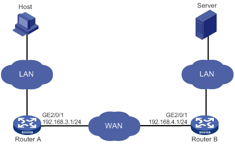
Configuration procedure
1. Configure IP addresses for interfaces. (Details not shown.)
2. Configure routing protocols to ensure connectivity. (Details not shown.)
3. Disable fast forwarding load sharing:
# Disable fast forwarding load sharing on Router A.
<RouterA> system-view
[RouterA] undo ip fast-forwarding load-sharing
# Disable fast forwarding load sharing on Router B.
<RouterB> system-view
[RouterB] undo ip fast-forwarding load-sharing
4. Apply the predefined WAAS policy to the interface GigabitEthernet 2/0/1 on Router A.
[RouterA] interface gigabitethernet 2/0/1
[RouterA-GigabitEthernet2/0/1] waas apply policy
[RouterA-GigabitEthernet2/0/1] quit
[RouterA] quit
5. Apply the predefined WAAS policy to the interface GigabitEthernet 2/0/1 on Router B.
[RouterB] interface gigabitethernet 2/0/1
[RouterB-GigabitEthernet2/0/1] waas apply policy
6. Download a test file of 14 MB from the server to the host.
7. Clear DRE statistics on Router A.
<RouterA> reset waas statistic dre
8. Download the same file from the server to the host.
Verifying the configuration
# After the first download, display DRE statistics on Router A.
<RouterA> display waas statistic dre
Peer-ID: cc3e-5fd8-5158
Peer version: 1.0
Cache in storage: 12710912 bytes
Index number: 49652
Age: 00 weeks, 00 days, 00 hours, 00 minutes, 35 seconds
Total connections: 1
Active connections: 0
Encode Statistics
Dre msgs: 2
Bytes in: 286 bytes
Bytes out: 318 bytes
Bypass bytes: 0 bytes
Bytes Matched: 0 bytes
Space saved: -11%
Average latency: 0 usec
Decode Statistics
Dre msgs: 57050
Bytes in: 14038391 bytes
Bytes out: 14079375 bytes
Bypass bytes: 0 bytes
Space saved: 0%
Average latency: 0 usec
# After the second download, display DRE statistics on Router A.
<RouterA> display waas statistic dre
Peer-ID: cc3e-5fd8-5158
Peer version: 1.0
Cache in storage: 12851200 bytes
Index number: 50200
Age: 00 weeks, 00 days, 00 hours, 2 minutes, 56 seconds
Total connections: 1
Active connections: 0
Encode Statistics
Dre msgs: 2
Bytes in: 286 bytes
Bytes out: 60 bytes
Bypass bytes: 0 bytes
Bytes Matched: 256 bytes
Space saved: 79%
Average latency: 0 usec
Decode Statistics
Dre msgs: 62791
Bytes in: 2618457 bytes
Bytes out: 13972208 bytes
Bypass bytes: 0 bytes
Space saved: 81%
Average latency: 0 usec
In the second download, the number of received bytes for decompression is much more smaller, and the download speed is much faster.
User-defined WAAS policy configuration example
Network requirements
As shown in Figure 174, configure and apply a user-defined WAAS policy on Router A and Router B.
The host downloads data from the server. Examine the optimization effect by comparing DRE statistics for the first download and second download.
· For the first download, both WAAS devices need to create data dictionary entries and Router A sends both indexes and metadata.
· For the second download, Router A replaces repeated data with indexes.
Configuration procedure
1. Configure IP addresses for interfaces. (Details not shown.)
2. Configure routing protocols to ensure connectivity. (Details not shown.)
3. Disable fast forwarding load sharing:
# Disable fast forwarding load sharing on Router A.
<RouterA> system-view
[RouterA] undo ip fast-forwarding load-sharing
# Disable fast forwarding load sharing on Router B.
<RouterB> system-view
[RouterB] undo ip fast-forwarding load-sharing
4. Configure WAAS classes:
# Create a WAAS class named c1 on Router A, and configure the WAAS class to match any TCP packets.
[RouterA-waasclass-c1] match 1 tcp any
[RouterA-waasclass-c1] quit
# Create a WAAS class named c1 on Router B, and configure the WAAS class to match any TCP packets.
[RouterB-waasclass-c1] match tcp any
[RouterB-waasclass-c1] quit
5. Configure WAAS policies:
# Create a WAAS policy named p1 on Router A, and specify the WAAS class c1. Configure TFO, DRE, and LZ optimization actions for the WAAS class.
[RouterA] waas policy p1
[RouterA-waaspolicy-p1] class c1
[RouterA-waaspolicy-p1-c1] optimize tfo dre lz
[RouterA-waaspolicy-p1-c1] quit
[RouterA-waaspolicy-p1] quit
# Create a WAAS policy named p1 on Router B, and specify the WAAS class c1. Configure TFO, DRE, and LZ optimization actions for the WAAS class.
[RouterB-waaspolicy-p1] class c1
[RouterB-waaspolicy-p1-c1] optimize tfo dre lz
[RouterB-waaspolicy-p1-c1] quit
[RouterB-waaspolicy-p1] quit
6. Apply WAAS policies:
# Apply the WAAS policy p1 to the interface GigabitEthernet 2/0/1 on Router A.
<RouterA> system-view
[RouterA] interface gigabitethernet 2/0/1
[RouterA-GigabitEthernet2/0/1] waas apply policy
[RouterA-GigabitEthernet2/0/1] quit
[RouterA] quit
# Apply the WAAS policy p1 to the interface GigabitEthernet 2/0/1 on Router B.
[RouterB] interface gigabitethernet 2/0/1
[RouterB-GigabitEthernet2/0/1] waas apply policy p1
[RouterB-GigabitEthernet2/0/1] quit
[RouterB] quit
7. Download a test file of 14 MB from the server to the host.
8. Clear DRE statistics on Router A.
<RouterA> reset waas statistic dre
9. Download the same file from the server to the host.
Verifying the configuration
# After the first download, display DRE statistics on Router A.
<RouterA> display waas statistic dre
Peer-ID: cc3e-5fd8-5158
Peer version: 1.0
Cache in storage: 12718592 bytes
Index number: 49682
Age: 00 weeks, 00 days, 00 hours, 00 minutes, 35 seconds
Total connections: 1
Active connections: 0
Encode Statistics
Dre msgs: 2
Bytes in: 286 bytes
Bytes out: 318 bytes
Bypass bytes: 0 bytes
Bytes Matched: 0 bytes
Space saved: -11%
Average latency: 0 usec
Decode Statistics
Dre msgs: 56959
Bytes in: 13999244 bytes
Bytes out: 14055291 bytes
Bypass bytes: 0 bytes
Space saved: 0%
Average latency: 0 usec
# After the second download, display DRE statistics on Router A.
<RouterA> display waas statistic dre
Peer-ID: cc3e-5fd8-5158
Peer version: 1.0
Cache in storage: 12857856 bytes
Index number: 50226
Age: 00 weeks, 00 days, 00 hours, 2 minutes, 02 seconds
Total connections: 1
Active connections: 0
Encode Statistics
Dre msgs: 2
Bytes in: 286 bytes
Bytes out: 60 bytes
Bypass bytes: 0 bytes
Bytes Matched: 256 bytes
Space saved: 79%
Average latency: 0 usec
Decode Statistics
Dre msgs: 62687
Bytes in: 2592183 bytes
Bytes out: 13972208 bytes
Bypass bytes: 0 bytes
Space saved: 81%
Average latency: 0 usec
In the second download, the number of received bytes for decompression is much more smaller, and the download speed is much faster.
Configuring lighttpd Web services
About lighttpd Web services
The device can act as a lighttpd Web server to support lightweight Web access to resources saved on the device. Supported resources include PHP dynamic webpages, pictures, flash files, video files, and advertisements. To access the resources on the lighttpd Web server, users only need to launch a Web browser and enter the IP address of the device in the address bar.
Feature and hardware compatibility
|
Hardware |
lighttpd Web service compatibility |
|
MSR810/810-W/810-W-DB/810-LM/810-W-LM/810-10-PoE/810-LM-HK/810-W-LM-HK/810-LMS/810-LUS |
Yes |
|
MSR2600-6-X1/2600-10-X1 |
No |
|
MSR 2630 |
No |
|
MSR3600-28/3600-51 |
No |
|
MSR3600-28-SI/3600-51-SI |
No |
|
MSR3610-X1/3610-X1-DP/3610-X1-DC/3610-X1-DP-DC |
No |
|
MSR 3610/3620/3620-DP/3640/3660 |
No |
|
MSR5620/5660/5680 |
No |
|
Hardware |
lighttpd Web service compatibility |
|
MSR810-LM-GL |
Yes |
|
MSR810-W-LM-GL |
Yes |
|
MSR830-6EI-GL |
Yes |
|
MSR830-10EI-GL |
Yes |
|
MSR830-6HI-GL |
Yes |
|
MSR830-10HI-GL |
Yes |
|
MSR2600-6-X1-GL |
No |
|
MSR3600-28-SI-GL |
No |
Restrictions and guidelines: lighttpd Web service configuration
The lighttpd Web server uses port 80 to provide HTTP access service and uses port 443 to provide HTTPS access service. You cannot change the port numbers. If any other service is using one of the ports, configure the service to use a different port.
Prerequisites
For the lighttpd Web server to provide HTTPS access service, save the required certificate to the lighttpd Web service working directory.
Procedure
|
Step |
Command |
Remarks |
|
1. Enter system view. |
system-view |
N/A |
|
2. Specify the lighttpd Web service working directory. |
light-http server directory directory |
By default, no lighttpd Web service working directory is specified. |
|
3. Save the resources for users to access the lighttpd Web service working directory. |
N/A |
N/A |
|
4. Enable the lighttpd Web server. |
light-http server enable |
By default, the lighttpd Web server is disabled. |
About lighttpd Web services,498
Address/prefix lease renewal,269
Advertising subnets assigned to clients,59
Advertising subnets assigned to clients,283
ADVPN configuration examples,395
ADVPN configuration task list,383
AFT configuration examples,473
AFT configuration task list,467
AFT implementations,463
AFT translation process,465
Applying a DHCP address pool to a VPN instance,60
Applying a DHCPv6 address pool to a VPN instance,284
Applying a WAAS policy to an interface,488
Applying an address pool on an interface,54
Applying the DDNS policy to an interface,128
ARP fast-reply configuration example,19
ARP PnP configuration example,21
ARP suppression configuration example,25
Assigning an IP address to an interface,28
Assigning IPv6 addresses to interfaces,241
Binding gateways to DHCP server's MAC address,59
BOOTP application,103
BOOTP client configuration example,104
Command and hardware compatibility,202
Command and hardware compatibility,133
Command and hardware compatibility,39
Command and hardware compatibility,215
Command and hardware compatibility,200
Command and hardware compatibility,3
Command and hardware compatibility,328
Common proxy ARP configuration example,14
Compatibility information,239
Compatibility information,270
Compatibility information,275
Compatibility information,309
Compatibility information,317
Compatibility information,208
Compatibility information,462
Compatibility information,297
Compatibility information,486
Compatibility information,291
Configuration examples,7
Configuration examples,30
Configuration prerequisites,20
Configuration procedure,18
Configuration procedure,16
Configuration procedure,11
Configuration procedure,21
Configuration procedure,211
Configuration procedure,24
Configuration procedure,26
Configuration restrictions and guidelines,225
Configuration restrictions and guidelines,487
Configuration restrictions and guidelines,297
Configuration task list,275
Configuring a 6RD tunnel,344
Configuring a 6to4 tunnel,336
Configuring a DDNS policy,126
Configuring a DHCP client ID for an interface,87
Configuring a DHCP packet blocking port,99
Configuring a DHCP policy for dynamic address assignment,54
Configuring a DHCP relay address pool,79
Configuring a DHCPv6 packet blocking port,314
Configuring a DHCPv6 policy for IPv6 address and prefix assignment,280
Configuring a DHCPv6 relay address pool,293
Configuring a DS-Lite tunnel,355
Configuring a GRE/IPv4 tunnel,367
Configuring a GRE/IPv6 tunnel,369
Configuring a static ARP entry,4
Configuring a tunnel interface,329
Configuring a WAAS class,487
Configuring a WAAS policy,487
Configuring AAA,383
Configuring address pool usage alarming,58
Configuring AFT logging,471
Configuring an address pool on the DHCP server,44
Configuring an ADVPN tunnel interface,391
Configuring an automatic IPv4-compatible IPv6 tunnel,334
Configuring an interface to use BOOTP for IP address acquisition,103
Configuring an IPv4 over IPv4 tunnel,349
Configuring an IPv4 over IPv6 manual tunnel,352
Configuring an IPv4-to-IPv6 destination address translation policy,469
Configuring an IPv4-to-IPv6 source address translation policy,470
Configuring an IPv6 over IPv4 manual tunnel,331
Configuring an IPv6 over IPv6 tunnel,358
Configuring an IPv6-to-IPv4 destination address translation policy,468
Configuring an IPv6-to-IPv4 source address translation policy,468
Configuring an ISATAP tunnel,341
Configuring basic DHCP snooping,95
Configuring basic DHCPv6 snooping,311
Configuring DHCP binding auto backup,58
Configuring DHCP server compatibility,56
Configuring DHCP snooping entry auto backup,96
Configuring DHCPv6 binding auto backup,282
Configuring DHCPv6 snooping entry auto backup,312
Configuring DNS spoofing,112
Configuring DRE optimization parameters,489
Configuring DS-Lite NAT444,151
Configuring dynamic NAT,145
Configuring fast forwarding load sharing,203
Configuring IP address conflict detection,55
Configuring IP unnumbered,29
Configuring IPsec for ADVPN tunnels,394
Configuring IPv6 address acquisition,298
Configuring IPv6 address and prefix acquisition,299
Configuring IPv6 address assignment,277
Configuring IPv6 fast forwarding load sharing,318
Configuring IPv6 load sharing based on bandwidth,258
Configuring IPv6 ND,245
Configuring IPv6 prefix acquisition,298
Configuring IPv6 prefix assignment,276
Configuring last hop holding,198
Configuring load sharing based on bandwidth,201
Configuring NAT ALG,154
Configuring NAT DNS mapping,153
Configuring NAT hairpin,154
Configuring NAT logging,155
Configuring NAT Server,147
Configuring NAT444,149
Configuring network mode tracking for an output interface,113
Configuring network parameters assignment,279
Configuring Option 18 and Option 37,311
Configuring Option 82,95
Configuring Option 82,78
Configuring path MTU discovery,253
Configuring per-packet or per-flow load sharing,200
Configuring rate limit for ICMP error messages,221
Configuring routing,393
Configuring stateless DHCPv6,299
Configuring static NAT,141
Configuring TCP path MTU discovery,217
Configuring TFO parameters,489
Configuring the aging time for fast forwarding entries,202
Configuring the aging time for IPv6 fast forwarding entries,318
Configuring the DHCP relay agent security features,76
Configuring the DHCP relay agent to forward DHCP replies based on Option 82,83
Configuring the DHCP relay agent to release an IP address,78
Configuring the DHCP smart relay feature,81
Configuring the DHCPv6 client DUID,299
Configuring the DHCPv6 server on an interface,281
Configuring the DNS proxy,111
Configuring the DNS trusted interface,114
Configuring the IPv4 DNS client,108
Configuring the IPv6 DNS client,110
Configuring the TFO blacklist autodiscovery feature,490
Configuring the VAM client,389
Configuring the VAM server,383
Configuring UDP helper to convert broadcast to multicast,226
Configuring UDP helper to convert broadcast to unicast,226
Configuring UDP helper to convert multicast to broadcast or unicast,227
Configuring WAAS to operate in asymmetric mode,488
Controlling sending ICMPv6 messages,254
DDNS client configuration task list,126
DDNS configuration examples,129
Deleting all WAAS settings,490
DHCP address allocation,34
DHCP client configuration example,89
DHCP message format,36
DHCP options,37
DHCP relay agent configuration examples,84
DHCP relay agent configuration task list,73
DHCP server configuration examples,62
DHCP server configuration task list,43
DHCP snooping configuration examples,100
DHCP snooping configuration task list,94
DHCPv6 address/prefix assignment,268
DHCPv6 client configuration examples,300
DHCPv6 client configuration task list,298
DHCPv6 relay agent configuration example,295
DHCPv6 relay agent configuration task list,291
DHCPv6 server configuration examples,285
DHCPv6 snooping configuration example,315
DHCPv6 snooping configuration task list,311
Displaying and maintaining ADVPN,394
Displaying and maintaining AFT,471
Displaying and maintaining ARP,6
Displaying and maintaining ARP PnP,21
Displaying and maintaining ARP snooping,17
Displaying and maintaining ARP suppression,24
Displaying and maintaining BOOTP client,104
Displaying and maintaining DHCP snooping,99
Displaying and maintaining DHCPv6 client,300
Displaying and maintaining DHCPv6 snooping,314
Displaying and maintaining DNS,114
Displaying and maintaining fast forwarding,203
Displaying and maintaining GRE,370
Displaying and maintaining IP addressing,30
Displaying and maintaining IP performance optimization,222
Displaying and maintaining IPv6 basics,258
Displaying and maintaining IPv6 fast forwarding,318
Displaying and maintaining NAT,158
Displaying and maintaining the DHCP client,88
Displaying and maintaining the DHCP relay agent,84
Displaying and maintaining the DHCP server,61
Displaying and maintaining the DHCPv6 relay agent,294
Displaying and maintaining the DHCPv6 server,285
Displaying and maintaining tunneling configuration,361
Displaying and maintaining UDP helper,228
Displaying and maintaining WAAS,491
Displaying commands,208
Displaying DDNS,129
Displaying FIB table entries,199
Displaying proxy ARP,13
DNS configuration task list,108
Enabling a device to discard IPv6 packets that contain extension headers,258
Enabling AFT,468
Enabling an interface to receive and forward directed broadcasts destined for the directly connected network,215
Enabling ARP logging,6
Enabling client offline detection on the DHCP relay agent,81
Enabling client offline detection on the DHCP server,61
Enabling common proxy ARP,13
Enabling DHCP,53
Enabling DHCP,74
Enabling DHCP logging on the DHCP server,61
Enabling DHCP server proxy on a DHCP relay agent,79
Enabling DHCP snooping logging,99
Enabling DHCP starvation attack protection,97
Enabling DHCP-REQUEST attack protection,98
Enabling DHCPv6 logging on the DHCPv6 server,284
Enabling DHCPv6 snooping logging,314
Enabling DHCPv6-REQUEST check,313
Enabling DSCP-based fast forwarding for GRE and VXLAN packet,203
Enabling duplicated address detection,88
Enabling dynamic ARP entry check,6
Enabling handling of Option 82,56
Enabling IP conflict notification,12
Enabling IPv4 local fragment reassembly,222
Enabling IPv6 local fragment reassembly,257
Enabling local proxy ARP,13
Enabling NAT reply redirection,157
Enabling router renumbering,257
Enabling sending ICMP error messages,219
Enabling sending ICMP error messages for NAT failures,157
Enabling TCP SYN Cookie,218
Enabling the deletion of timestamps in TCP SYN and SYN ACK packets,157
Enabling the DHCP client on an interface,87
Enabling the DHCP relay agent on an interface,74
Enabling the DHCP server on an interface,53
Enabling the DHCPv6 relay agent on an interface,292
Feature and hardware compatibility,16
Feature and hardware compatibility,225
Feature and hardware compatibility,23
Feature and hardware compatibility,94
Feature and hardware compatibility,126
Feature and hardware compatibility,498
Feature and hardware compatibility,205
Feature and hardware compatibility,18
Feature and hardware compatibility,382
Feature and hardware compatibility,211
Feature and hardware compatibility,108
Feature and hardware compatibility,20
FIB table,198
GRE configuration examples,371
H3C implementation of Option 18 and Option 37,309
IPv4 DNS configuration examples,115
IPv6 basics configuration task list,240
IPv6 configuration examples,262
IPv6 DNS configuration examples,119
IPv6 transition technologies,238
IRDP configuration example,212
NAT configuration examples,160
NAT configuration restrictions and guidelines,141
NAT configuration task list,140
NAT entries,138
NAT implementations,133
Obtaining an IP address dynamically,103
Overview,27
Overview,105
Overview,26
Overview,232
Overview,92
Overview,41
Overview,10
Overview,225
Overview,72
Overview,202
Overview,1
Overview,320
Overview,125
Overview,484
Overview,317
Overview,23
Overview,363
Overview,377
Overview,132
Overview,272
Overview,462
Overview,210
Overview,290
Overview,297
Overview,20
Overview,16
Overview,18
Overview,308
Overview,207
Prerequisites,498
Procedure,498
Protocols and standards,103
Protocols and standards,271
Protocols and standards,240
Protocols and standards,40
Rearranging NAT rules to adjust their priorities,152
Restoring predefined WAAS settings,491
Restrictions and guidelines: lighttpd Web service configuration,498
Setting MTU for an interface,217
Setting TCP MSS for an interface,217
Setting TCP timers,219
Setting the aging timer for dynamic ARP entries,5
Setting the DSCP value for DHCP packets sent by the DHCP client,88
Setting the DSCP value for DHCP packets sent by the DHCP relay agent,79
Setting the DSCP value for DHCP packets sent by the DHCP server,57
Setting the DSCP value for DHCPv6 packets sent by the DHCPv6 client,300
Setting the DSCP value for DHCPv6 packets sent by the DHCPv6 relay agent,292
Setting the DSCP value for DHCPv6 packets sent by the DHCPv6 server,282
Setting the DSCP value for outgoing DDNS packets,129
Setting the DSCP value for outgoing DNS packets,114
Setting the maximum number of DHCP snooping entries,98
Setting the maximum number of DHCPv6 snooping entries,313
Setting the maximum number of dynamic ARP entries for a device,4
Setting the maximum number of dynamic ARP entries for an interface,5
Setting the TCP buffer size,219
Setting the ToS field to 0 for translated IPv4 packets,471
Setting the Traffic Class field to 0 for translated IPv6 packets,471
Specifying a flow classification policy,205
Specifying a gateway address for DHCP clients,80
Specifying a gateway address for DHCPv6 clients,294
Specifying a padding mode for the Interface-ID option,293
Specifying DHCP servers on a relay agent,75
Specifying DHCPv6 servers on the relay agent,292
Specifying the source address and gateway address in DHCP requests,75
Specifying the source address for ICMP packets,221
Specifying the source interface for DNS packets,113
Stateless DHCPv6,270
Troubleshooting DHCP relay agent configuration,86
Troubleshooting DHCP server configuration,71
Troubleshooting GRE,375
Troubleshooting IPv4 DNS configuration,124
Troubleshooting IPv6 basics configuration,267
Troubleshooting IPv6 DNS configuration,124
Troubleshooting tunneling configuration,362
Tunneling configuration task list,329
UDP helper configuration examples,228
Using NAT with other features,139
WAAS configuration examples,492
WAAS configuration task list,487