- Table of Contents
- Related Documents
-
| Title | Size | Download |
|---|---|---|
| 01-Text | 2.16 MB |
Entering system view from user view
Returning to the upper-level view from any view
Using the undo form of a command
Entering a text or string type value for an argument
Configuring and using command aliases
Configuring and using command hotkeys
Enabling redisplaying entered-but-not-submitted commands
Understanding command-line error messages
Using the command history feature
Repeating commands in the command history buffer for a line
Pausing between screens of output
Numbering each output line from a display command
Filtering the output from a display command
Saving the output from a display command to a file
Viewing and managing the output from a display command effectively
Saving the running configuration
Configuration restrictions and guidelines
Configuring resource access policies
Configuring the user role interface policy
Configuring the user role VLAN policy
Configuring the user role VPN instance policy
Configuring the user role security zone policy
Enabling the default user role feature
Assigning user roles to remote AAA authentication users
Assigning user roles to local AAA authentication users
Assigning user roles to non-AAA authentication users on user lines
Configuring temporary user role authorization
Configuring user role authentication
Obtaining temporary user role authorization
Displaying and maintaining RBAC settings
RBAC configuration example for local AAA authentication users
RBAC configuration example for RADIUS authentication users
RBAC temporary user role authorization configuration example (HWTACACS authentication)
RBAC temporary user role authorization configuration example (RADIUS authentication)
Local users have more access permissions than intended
Login attempts by RADIUS users always fail
Feature and hardware compatibility
Using the console port for the first device access
Configuring local console or AUX login·
Disabling authentication for console or AUX login
Configuring password authentication for console or AUX login
Configuring scheme authentication for console or AUX login
Configuring common console or AUX line settings
Configuring the device as a Telnet server
Using the device to log in to a Telnet server
Configuring the device as an SSH server
Using the device to log in to an SSH server
Displaying and maintaining CLI login
Accessing the device through SNMP
Controlling user access to the device·
Feature and hardware compatibility
Controlling Telnet and SSH logins
Configuring command authorization
Configuring command accounting
Command and hardware compatibility
Using the device as an FTP server
Configuring authentication and authorization
Manually releasing FTP connections
Displaying and maintaining the FTP server
FTP server configuration example (centralized devices in standalone mode)
FTP server configuration example (distributed devices in standalone mode)
FTP server configuration example (centralized devices in IRF mode)
FTP server configuration example (distributed devices in IRF mode)
Using the device as an FTP client
Establishing an FTP connection
Managing directories on the FTP server
Working with files on the FTP server
Changing to another user account
Maintaining and troubleshooting the FTP connection
Terminating the FTP connection
Displaying command help information
Displaying and maintaining the FTP client
FTP client configuration example (centralized devices in standalone mode)
FTP client configuration example (distributed devices in standalone mode)
FTP client configuration example (centralized devices in IRF mode)
FTP client configuration example (distributed devices in IRF mode)
Command and hardware compatibility
Configuring the device as an IPv4 TFTP client
Configuring the device as an IPv6 TFTP client
Specifying a directory name or file name
Command and hardware compatibility
File system management restrictions and guidelines
Managing storage media and file systems
Mounting or unmounting a file system
Displaying directory information
Displaying the working directory
Changing the working directory
Archiving or extracting directories
Setting the operation mode for directories·
Displaying the contents of a text file
Compressing or decompressing a file
Deleting files from the recycle bin
Setting the operation mode for files
Using the automatic copying feature
Synchronizing files and directories from an Rsync server
Next-startup configuration file redundancy
Startup configuration file selection
Configuration file content organization and format
Command and hardware compatibility
Enabling configuration encryption
Comparing configurations for their differences
Saving the running configuration
Configuration restrictions and guidelines
Using different methods to save the running configuration
Configuring configuration rollback
Setting configuration archive parameters
Enabling automatic configuration archiving
Manually archiving the running configuration
Specifying a next-startup configuration file
Backing up the main next-startup configuration file to a TFTP server
Restoring the main next-startup configuration file from a TFTP server
Deleting a next-startup configuration file
Displaying and maintaining configuration files
Comware image redundancy and loading procedure
Command and hardware compatibility
Upgrade restrictions and guidelines
Specifying startup images and completing the upgrade
Centralized devices in standalone mode
Distributed devices in standalone mode
Centralized devices in IRF mode
Distributed devices in IRF mode
Performing an upgrade by using install commands
Installing or upgrading software images
Uninstalling feature or patch images
Rolling back the running software images
Aborting a software activate/deactivate operation
Deleting inactive software images
Enabling software synchronization from the active MPU to the standby MPU at startup
Displaying and maintaining software image settings
Centralized devices in standalone mode
Centralized devices in IRF mode
Distributed devices in standalone mode
Distributed devices in IRF mode
Software upgrade examples by using the boot-loader file command
Software upgrade example (centralized devices in standalone mode)
Software upgrade example (distributed devices in standalone mode)
Software upgrade example (centralized devices in IRF mode)
Software upgrade example (distributed devices in IRF mode)
Software upgrade examples by using install commands (centralized devices in standalone mode)
Software upgrade examples by using install commands (distributed devices in standalone mode)
Software upgrade examples by using install commands (centralized devices in IRF mode)
Software upgrade examples by using install commands (distributed devices in IRF mode)
Command and hardware compatibility
Identifying availability of ISSU and licensing requirements
Verifying the device operating status
Adjusting and saving the running configuration
Logging in to the device through the console port
Performing an ISSU by using install commands
Installing or upgrading software images
Uninstalling feature or patch images
Rolling back the running software images
Aborting a software activate/deactivate operation
Deleting inactive software images
Displaying and maintaining ISSU
Centralized devices in standalone mode
Centralized devices in IRF mode
Distributed devices in standalone mode
Distributed devices in IRF mode
Examples of using install commands for ISSU (centralized devices in standalone mode)
Examples of using install commands for ISSU (distributed devices in standalone mode)
Examples of using install commands for ISSU (centralized devices in IRF mode)
Examples of using install commands for ISSU (distributed devices in IRF mode)
Feature and hardware compatibility
Command and hardware compatibility
Obtaining a system image from an FTP/TFTP server
Configuring the management Ethernet interface
Checking the connectivity to a server
Displaying device information in emergency shell mode
Feature and hardware compatibility
Using server-based automatic configuration
Server-based automatic configuration task list
Preparing the files for automatic configuration
Preparing the interface used for automatic configuration
Starting and completing automatic configuration
Using USB-based automatic configuration
Preparing the USB disk for automatic configuration
USB-based automatic configuration procedure
Using SMS-based automatic configuration
Preparing for SMS-based automatic configuration
Starting and completing SMS-based automatic configuration
Server-based automatic configuration examples
Automatic configuration using TFTP server
Automatic configuration using HTTP server and Tcl script
Automatic configuration using HTTP server and Python script
Security zone-based security management
Feature and hardware compatibility
Security zone configuration task list
Adding members to a security zone
Specifying the default action for packets between interfaces in the same security zone
Security zone configuration example
Command and hardware compatibility
Enabling displaying the copyright statement
Rebooting devices immediately at the CLI
Schedule configuration example
Disabling password recovery capability·
Enabling power supply management
Specifying the number of redundant power supplies
Setting the port status detection timer
Setting memory alarm thresholds
Setting the operating mode for an interface card
Verifying and diagnosing transceiver modules
Diagnosing transceiver modules·
Restoring the factory-default configuration
Updating the modem firmware through FoTA
Displaying and maintaining device management configuration
Using Tcl to configure the device·
Executing Comware commands in Tcl configuration view
Feature and hardware compatibility
Command and hardware compatibility
Importing and using the Comware 7 extended Python API
Comware 7 extended Python API functions·
Feature and hardware compatibility
Registering licenses for the first time
Using the CLI
At the command-line interface (CLI), you can enter text commands to configure, manage, and monitor the device. The following text is displayed when you access the CLI:
******************************************************************************
* Copyright (c) 2004-2017 New H3C Technologies Co., Ltd. All rights reserved.*
* Without the owner's prior written consent, *
* no decompiling or reverse-engineering shall be allowed. *
******************************************************************************
<Sysname>
You can use different methods to log in to the CLI, including through the console port, Telnet, and SSH. For more information about login methods, see "Login overview."
CLI views
Commands are grouped in different views by feature. To use a command, you must enter its view.
CLI views are hierarchically organized, as shown in Figure 1. Each view has a unique prompt, from which you can identify where you are and what you can do. For example, the prompt [Sysname-vlan100] shows that you are in VLAN 100 view and can configure attributes for that VLAN.
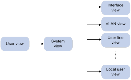
You are placed in user view immediately after you log in to the CLI. The user view prompt is <Device-name>, where Device-name indicates the device name. The device name is Sysname by default. You can change it by using the sysname command.
In user view, you can perform the following tasks:
· Perform basic operations including display, debug, file management, FTP, Telnet, clock setting, and reboot.
· Enter system view. The system view prompt is [Device-name].
In system view, you can perform the following tasks:
· Configure settings that affect the device as a whole, such as the daylight saving time, banners, and hotkeys.
· Enter different feature views.
For example, you can perform the following tasks:
? Enter interface view to configure interface parameters.
? Enter VLAN view to add ports to the VLAN.
? Enter user line view to configure login user attributes.
A feature view might have child views. For example, BGP view has child views IPv4 unicast instance view and BGP-VPN IPv4 unicast instance view.
To display all commands available in a view, enter a question mark (?) at the view prompt.
Entering system view from user view
|
Task |
Command |
|
Enter system view. |
system-view |
Returning to the upper-level view from any view
|
Task |
Command |
|
Return to the upper-level view from any view. |
quit |
Executing the quit command in user view terminates your connection to the device.
In public key view, use the peer-public-key end command to return to system view.
Returning to user view
To return directly to user view from any other view, use the return command or press Ctrl+Z.
|
Task |
Command |
|
Return directly to user view. |
return |
Accessing the CLI online help
The CLI online help is context sensitive. Enter a question mark at any prompt or in any position of a command to display all available options.
To access the CLI online help, use one of the following methods:
· Enter a question mark at a view prompt to display the first keyword of every command available in the view. For example:
<Sysname> ?
User view commands:
archive Archive configuration
backup Backup operation
boot-loader Software image file management
bootrom Update/read/backup/restore bootrom
cd Change current directory
...
· Enter a space and a question mark after a command keyword to display all available keywords and arguments at the position.
? If the question mark is in the place of a keyword, the CLI displays all possible keywords, each with a brief description. For example:
<Sysname> terminal ?
debugging Enable to display debugging logs on the current terminal
logging Display logs on the current terminal
monitor Enable to display logs on the current terminal
? If the question mark is in the place of an argument, the CLI displays the description for the argument. For example:
<Sysname> system-view
[Sysname] interface vlan-interface ?
<1-4094> Vlan-interface interface number
[Sysname] interface vlan-interface 1 ?
<cr>
[Sysname] interface vlan-interface 1
<1-4094> is the value range for the argument. <cr> indicates that the command is complete and you can press Enter to execute the command.
· Enter an incomplete keyword string followed by a question mark to display all keywords starting with that string. The CLI also displays the descriptions for the keywords. For example:
<Sysname> a?
archive Archive configuration
<Sysname> display ftp?
ftp FTP module
ftp-server FTP server information
ftp-user FTP user information
Using the undo form of a command
Most configuration commands have an undo form for the following tasks:
· Canceling a configuration.
· Restoring the default.
· Disabling a feature.
For example, the info-center enable command enables the information center. The undo info-center enable command disables the information center.
Entering a command
When you enter a command, you can perform the following tasks:
· Use keys or hotkeys to edit the command line.
· Use abbreviated keywords or keyword aliases.
Editing a command line
To edit a command line, use the keys listed in Table 1 or the hotkeys listed in Table 4. When you are finished, you can press Enter to execute the command.
Table 1 Command line editing keys
|
Keys |
Function |
|
Common keys |
If the edit buffer is not full, pressing a common key inserts a character at the cursor and moves the cursor to the right. The edit buffer can store up to 511 characters. Unless the buffer is full, all common characters that you enter before pressing Enter are saved in the edit buffer. |
|
Backspace |
Deletes the character to the left of the cursor and moves the cursor back one character. |
|
Left arrow key (←) |
Moves the cursor one character to the left. |
|
Right arrow key (→) |
Moves the cursor one character to the right. |
|
Up arrow key (↑) |
Displays the previous command in the command history buffer. |
|
Down arrow key (↓) |
Displays the next command in the command history buffer. |
|
Tab |
If you press Tab after typing part of a keyword, the system automatically completes the keyword. · If a unique match is found, the system displays the complete keyword. · If there is more than one match, press Tab multiple times to pick the keyword you want to enter. · If there is no match, the system does not modify what you entered but displays it again in the next line. |
The total length of a command line cannot exceed 512 characters, including spaces and special characters.
The device supports the following special commands:
· #–Used by the system in a configuration file as separators for adjacent sections.
· version–Used by the system in a configuration file to indicate the software version information. For example, Version 7.1.064, ESS 0401L13.
These commands are special because of the following reasons:
· These commands are not intended for you to use at the CLI.
· You can enter these commands in any view, or enter any values for them. For example, you can enter # abc or version abc. However, the settings do not take effect.
· The device does not provide any online help information for these commands.
Entering a text or string type value for an argument
A text type argument value can contain any characters except question marks (?).
A string type argument value can contain any printable characters except question marks (?).
· To include a quotation mark (") or backward slash (\) in a string type argument value, prefix the character with an escape key (\), for example, \" and \\.
· To include a blank space in a string type argument value, enclose the value in quotation marks, for example, ''my device''.
To enter a printable character, you can enter the character or its ASCII code in the range of 32 to 126.
Entering an interface type
You can enter an interface type in one of the following formats:
· Full spelling of the interface type.
· An abbreviation that uniquely identifies the interface type.
· Acronym of the interface type.
For a command line, all interface types are case insensitive. Table 2 shows the full spellings and acronyms of interface types.
For example, to use the interface command to enter the view of interface GigabitEthernet 1/0/1, you can enter the command line in the following formats:
· interface gigabitethernet 1/0/1
· interface g 1/0/1
· interface ge 1/0/1
· interface gigabitethernet1/0/1
· interface g1/0/1
· interface ge1/0/1
Table 2 Full spellings and acronyms of interface types
|
Full spelling |
Acronym |
|
Route-Aggregation |
RAGG |
|
Dialer |
Dia |
|
LoopBack |
Loop |
|
GigabitEthernet |
GE |
|
Ten-GigabitEthernet |
XGE |
|
Virtual-Ethernet |
VEth |
|
M-GigabitEthernet |
MGE |
|
MP-group |
MP |
|
Serial |
Ser |
|
Tunnel |
Tun |
|
Vlan-interface |
Vlan-int |
|
Virtual-Template |
VT |
|
Bridge-Aggregation |
BAGG |
|
Route-Aggregation |
RAGG |
|
FortyGigE |
FGE |
|
Virtual-PPP |
VPPP |
|
HDLC-bundle |
HDLC-B |
|
Tunnel-Bundle |
Tunnel-B |
|
VE-L2VPN |
L2VE |
|
VE-L3VPN |
L3VE |
Abbreviating commands
You can enter a command line quickly by entering incomplete keywords that uniquely identify the complete command. In user view, for example, commands starting with an s include startup saved-configuration and system-view. To enter the command system-view, you need to type only sy. To enter the command startup saved-configuration, type st s.
You can also press Tab to complete an incomplete keyword.
Configuring and using command aliases
For example, if you configure the alias siprt for display ip routing-table, you can enter siprt to execute the display ip routing-table command. If you configure the alias ship for display ip, you can use ship to execute all commands starting with display ip:
· Enter ship routing-table to execute the display ip routing-table command.
· Enter ship interface to execute the display ip interface command.
Usage guidelines
After you successfully execute a command by using an alias, the system saves the command, instead of the alias, to the running configuration.
The command string represented by an alias can include up to nine parameters. Each parameter starts with the dollar sign ($) and a sequence number in the range of 1 to 9. For example, you can configure the alias shinc for the display $1 | include $2 command. Then, you can enter shinc hotkey CTRL_C to execute the display hotkey | include CTRL_C command.
To use an alias for a command that has parameters, you must specify a value for each parameter. If you fail to do so, the system informs you that the command is incomplete and displays the command string represented by the alias.
The device has a set of system-defined command aliases, as listed in Table 3. System-defined command aliases cannot be deleted.
Table 3 System-defined command aliases
|
Command alias |
Command or command keyword |
Configuration procedure
To configure a command alias:
|
Step |
Command |
Remarks |
|
1. Enter system view. |
system-view |
N/A |
|
2. Configure a command alias. |
alias alias command |
By default, the device has a set of command aliases, as listed in Table 3. |
|
3. (Optional.) Display command aliases. |
display alias [ alias ] |
This command is available in any view. |
Configuring and using command hotkeys
The system defines the hotkeys shown in Table 4 and provides five configurable command hotkeys. Pressing a command hotkey is the same as entering a command.
If a hotkey is also defined by the terminal software you are using to interact with the device, the terminal software definition takes effect.
To configure a command hotkey:
|
Step |
Command |
Remarks |
|
1. Enter system view. |
system-view |
N/A |
|
2. Assign a command to a hotkey. |
hotkey { ctrl_g | ctrl_l | ctrl_o | ctrl_t | ctrl_u } command |
The following are the defaults: · Ctrl+G is assigned the display current-configuration command. · Ctrl+L is assigned the display ip routing-table command. · Ctrl+O is assigned the undo debugging all command. · No command is assigned to Ctrl+T or Ctrl+U. |
|
3. (Optional.) Display hotkeys. |
display hotkey |
This command is available in any view. |
Table 4 System-reserved hotkeys
|
Hotkey |
Function |
|
Ctrl+A |
Moves the cursor to the beginning of a line. |
|
Ctrl+B |
Moves the cursor one character to the left. |
|
Ctrl+C |
Stops the current command. |
|
Ctrl+D |
Deletes the character at the cursor. |
|
Ctrl+E |
Moves the cursor to the end of a line. |
|
Ctrl+F |
Moves the cursor one character to the right. |
|
Ctrl+H |
Deletes the character to the left of the cursor. |
|
Ctrl+K |
Aborts the connection request. |
|
Ctrl+N |
Displays the next command in the history buffer. This hotkey is not supported in the current software version. |
|
Ctrl+P |
Displays the previous command in the history buffer. |
|
Ctrl+R |
Redisplays the current line. |
|
Ctrl+V |
Pastes text from the clipboard. |
|
Ctrl+W |
Deletes the word to the left of the cursor. |
|
Ctrl+X |
Deletes all characters to the left of the cursor. |
|
Ctrl+Y |
Deletes all characters from the cursor to the end of the line. |
|
Ctrl+Z |
Returns to user view. |
|
Ctrl+] |
Terminates the current connection. |
|
Esc+B |
Moves the cursor back one word. |
|
Esc+D |
Deletes all characters from the cursor to the end of the word. |
|
Esc+F |
Moves the cursor forward one word. |
|
Esc+N |
Moves the cursor down one line. You can use this hotkey before pressing Enter. This hotkey is not supported in the current software version. |
|
Esc+P |
Moves the cursor up one line. You can use this hotkey before pressing Enter. This hotkey is not supported in the current software version. |
|
Esc+< |
Moves the cursor to the beginning of the clipboard. |
|
Esc+> |
Moves the cursor to the end of the clipboard. |
Enabling redisplaying entered-but-not-submitted commands
Your input might be interrupted by system information output. If redisplaying entered-but-not-submitted commands is enabled, the system redisplays your input after finishing the output. You can then continue entering the command line.
To enable redisplaying entered-but-not-submitted commands:
|
Step |
Command |
Remarks |
|
1. Enter system view. |
system-view |
N/A |
|
2. Enable redisplaying entered-but-not-submitted commands. |
info-center synchronous |
By default, the system does not redisplay entered-but-not-submitted commands. For more information about this command, see Network Management and Monitoring Command Reference. |
Understanding command-line error messages
After you press Enter to submit a command, the command line interpreter examines the command syntax.
· If the command passes syntax check, the CLI executes the command.
· If the command fails syntax check, the CLI displays an error message.
Table 5 Common command-line error messages
|
Error message |
Cause |
|
% Unrecognized command found at '^' position. |
The keyword in the marked position is invalid. |
|
% Incomplete command found at '^' position. |
One or more required keywords or arguments are missing. |
|
% Ambiguous command found at '^' position. |
The entered character sequence matches more than one command. |
|
% Too many parameters. |
The entered character sequence contains excessive keywords or arguments. |
|
% Wrong parameter found at '^' position. |
The argument in the marked position is invalid. |
Using the command history feature
The system automatically saves commands successfully executed by a login user to the following two command history buffers:
· Command history buffer for the user line.
· Command history buffer for all user lines.
Table 6 Comparison between the two types of command history buffers
|
Item |
Command history buffer for a user line |
Command history buffer for all user lines |
|
What kind of commands are saved in the buffer? |
Commands successfully executed by the current user of the user line. |
Commands successfully executed by all login users. |
|
Cleared when the user logs out? |
Yes. |
No. |
|
How to view buffered commands? |
Use the display history-command command. |
Use the display history-command all command. |
|
How to recall a buffered command? |
· (Method 1.) Use the up or down arrow key (↑ or ↓) to navigate to the command in the buffer and press Enter. · (Method 2.) Use the repeat command. For more information, see "Repeating commands in the command history buffer for a line." |
You cannot recall buffered commands. |
|
How to set the buffer size? |
Use the history-command max-size size-value command in user line view to set the buffer size. By default, the buffer can store up to 10 commands. |
You cannot set the buffer size. The buffer can store up to 1024 commands. |
|
How to disable the buffer? |
Setting the buffer size to 0 disables the buffer. |
You cannot disable the buffer. |
Command buffering rules
The system follows these rules when buffering commands:
· If you use incomplete keywords when entering a command, the system buffers the command in the exact form that you used.
· If you use an alias when entering a command, the system transforms the alias to the represented command or command keywords before buffering the command.
· If you enter a command in the same format multiple times in succession, the system buffers the command only once. If you enter a command in different formats multiple times, the system buffers each command format. For example, display cu and display current-configuration are buffered as two entries but successive repetitions of display cu create only one entry.
· To buffer a new command when a buffer is full, the system deletes the oldest command entry in the buffer.
Repeating commands in the command history buffer for a line
You can recall and execute commands in the command history buffer for the current user line multiple times.
To repeat commands in the command history buffer for the current user line:
|
Task |
Command |
Remarks |
|
Repeat commands in the command history buffer for the current CLI session. |
This command is available in any view. However, to repeat a command, you must first enter the view for the command. To repeat multiple commands, you must first enter the view for the first command. This command executes commands in the order they were executed. The system waits for your interaction when it repeats an interactive command. |
Controlling the CLI output
This section describes the CLI output control features that help you identify the desired output.
Pausing between screens of output
By default, the system automatically pauses after displaying a maximum of 24 lines if the output is too long to fit on one screen. You can change the limit by using the screen-length screen-length command. For more information about this command, see Fundamentals Command Reference.
At a pause, the system displays ----more----. You can use the keys described in "Output controlling keys" to display more information or stop the display.
You can also disable pausing between screens of output for the current session. Then, all output is displayed at one time and the screen is refreshed continuously until the final screen is displayed.
Output controlling keys
|
Keys |
Function |
|
Space |
Displays the next screen. |
|
Enter |
Displays the next line. |
|
Ctrl+C |
Stops the display and cancels the command execution. |
|
<PageUp> |
Displays the previous page. |
|
<PageDown> |
Displays the next page. |
Disabling pausing between screens of output
To disable pausing between screens of output, execute the following command in user view:
|
Task |
Command |
Remarks |
|
Disable pausing between screens of output for the current CLI session. |
screen-length disable |
By default, a CLI session uses the screen-length screen-length command settings in user line view. This command is a one-time command and takes effect only for the current CLI session. |
Numbering each output line from a display command
You can use the | by-linenum option to prefix each display command output line with a number for easy identification.
Each line number is displayed as a 5-character string and might be followed by a colon (:) or hyphen (-). If you specify both | by-linenum and | begin regular-expression for a display command, a hyphen is displayed for all lines that do not match the regular expression.
To number each output line from a display command:
|
Task |
Command |
|
Number each output line from a display command. |
display command | by-linenum |
For example:
# Display information about VLAN 999, numbering each output line.
<Sysname> display vlan 999 | by-linenum
1: VLAN ID: 999
2: VLAN type: Static
3: Route interface: Configured
4: IPv4 address: 192.168.2.1
5: IPv4 subnet mask: 255.255.255.0
6: Description: For LAN Access
7: Name: VLAN 0999
8: Tagged ports: None
9: Untagged ports:
10: GigabitEthernet1/0/1
Filtering the output from a display command
You can use the | { begin | exclude | include } regular-expression option to filter the display command output.
· begin—Displays the first line matching the specified regular expression and all subsequent lines.
· exclude—Displays all lines not matching the specified regular expression.
· include—Displays all lines matching the specified regular expression.
· regular-expression—A case-sensitive string of 1 to 256 characters, which can contain the special characters described in Table 7.
The required filtering time increases with the complexity of the regular expression. To abort the filtering process, press Ctrl+C.
Table 7 Special characters supported in a regular expression
|
Characters |
Meaning |
Examples |
|
^ |
Matches the beginning of a line. |
"^u" matches all lines beginning with "u". A line beginning with "Au" is not matched. |
|
$ |
Matches the end of a line. |
"u$" matches all lines ending with "u". A line ending with "uA" is not matched. |
|
. (period) |
Matches any single character. |
".s" matches "as" and "bs". |
|
* |
Matches the preceding character or string zero, one, or multiple times. |
"zo*" matches "z" and "zoo", and "(zo)*" matches "zo" and "zozo". |
|
+ |
Matches the preceding character or string one or multiple times. |
"zo+" matches "zo" and "zoo", but not "z". |
|
| |
Matches the preceding or succeeding string. |
"def|int" matches a line containing "def" or "int". |
|
( ) |
Matches the string in the parentheses, usually used together with the plus sign (+) or asterisk sign (*). |
"(123A)" matches "123A". "408(12)+" matches "40812" and "408121212", but not "408". |
|
\N |
Matches the preceding strings in parentheses, with the Nth string repeated once. |
"(string)\1" matches a string containing "stringstring". "(string1)(string2)\2" matches a string containing "string1string2string2". "(string1)(string2)\1\2" matches a string containing " string1string2string1string2". |
|
[ ] |
Matches a single character in the brackets. |
"[16A]" matches a string containing 1, 6, or A; "[1-36A]" matches a string containing 1, 2, 3, 6, or A (- is a hyphen). To match the character "]", put it immediately after "[", for example, []abc]. There is no such limit on "[". |
|
[^] |
Matches a single character that is not in the brackets. |
"[^16A]" matches a string that contains one or more characters except for 1, 6, or A, such as "abc". A match can also contain 1, 6, or A (such as "m16"), but it cannot contain these three characters only (such as 1, 16, or 16A). |
|
{n} |
Matches the preceding character n times. The number n must be a nonnegative integer. |
"o{2}" matches "food", but not "Bob". |
|
{n,} |
Matches the preceding character n times or more. The number n must be a nonnegative integer. |
"o{2,}" matches "foooood", but not "Bob". |
|
{n,m} |
Matches the preceding character n to m times or more. The numbers n and m must be nonnegative integers and n cannot be greater than m. |
" o{1,3}" matches "fod", "food", and "foooood", but not "fd". |
|
\< |
Matches a string that starts with the pattern following \<. A string that contains the pattern is also a match if the characters preceding the pattern are not digits, letters, or underscores. |
"\<do" matches "domain" and "doa". |
|
\> |
Matches a string that ends with the pattern preceding \>. A string that contains the pattern is also a match if the characters following the pattern are not digits, letters, or underscores. |
"do\>" matches "undo" and "cdo". |
|
\b |
Matches a word that starts with the pattern following \b or ends with the pattern preceding \b. |
"er\b" matches "never", but not "verb" or "erase". "\ber" matches "erase", but not "verb" or "never". |
|
\B |
Matches a word that contains the pattern but does not start or end with the pattern. |
"er\B" matches "verb", but not "never" or "erase". |
|
\w |
Same as [A-Za-z0-9_], matches a digit, letter, or underscore. |
"v\w" matches "vlan" and "service". |
|
\W |
Same as [^A-Za-z0-9_], matches a character that is not a digit, letter, or underscore. |
"\Wa" matches "-a", but not "2a" or "ba". |
|
\ |
Escape character. If a special character listed in this table follows \, the specific meaning of the character is removed. |
"\\" matches a string containing "\", "\^" matches a string containing "^", and "\\b" matches a string containing "\b". |
For example:
# Use | begin line for the display current-configuration command to match the first line of output that contains line to the last line of output.
<Sysname> display current-configuration | begin line
line class console
user-role network-admin
#
line class tty
user-role network-operator
#
line class vty
user-role network-operator
#
line con 0
user-role network-admin
#
line vty 0 63
authentication-mode none
user-role network-admin
user-role network-operator
#
return
# Use | exclude Direct for the display ip routing-table command to filter out direct routes and display only the non-direct routes.
<Sysname> display ip routing-table | exclude Direct
Destinations : 12 Routes : 12
Destination/Mask Proto Pre Cost NextHop Interface
2.2.2.0/24 OSPF 10 2 1.1.2.2 GE0/1
# Use | include snmp for the display current-configuration command to filter in entries that contain snmp.
<Sysname> display current-configuration | include snmp
snmp-agent
snmp-agent community write private
snmp-agent community read public
snmp-agent sys-info version all
snmp-agent target-host trap address udp-domain 192.168.1.26 params securityname public
Saving the output from a display command to a file
A display command shows certain configuration and operation information of the device. Its output might vary over time or with user configuration or operation. You can save the output to a file for future retrieval or troubleshooting.
Use one of the following methods to save the output from a display command:
· Save the output to a separate file. Use this method if you want to use one file for a single display command.
· Append the output to the end of a file. Use this method if you want to use one file for multiple display commands.
To save the output from a display command to a file, use one of the following commands in any view:
|
Task |
Command |
|
Save the output from a display command to a separate file. |
display command > filename |
|
Append the output from a display command to the end of a file. |
display command >> filename |
For example:
# Save the VLAN 1 settings to a separate file named vlan.txt.
<Sysname> display vlan 1 > vlan.txt
# Verify that the VLAN 1 settings are saved to file vlan.txt.
<Sysname> more vlan.txt
VLAN ID: 1
VLAN type: Static
Route interface: Not configured
Description: VLAN 0001
Name: VLAN 0001
Tagged ports: None
Untagged ports:
GigabitEthernet1/0/2
# Append the VLAN 999 settings to the end of file vlan.txt.
<Sysname> display vlan 999 >> vlan.txt
# Verify that the VLAN 999 settings are appended to the end of file vlan.txt.
<Sysname> more vlan.txt
VLAN ID: 1
VLAN type: Static
Route interface: Not configured
Description: VLAN 0001
Name: VLAN 0001
Tagged ports: None
Untagged ports:
GigabitEthernet1/0/2
VLAN ID: 999
VLAN type: Static
Route interface: Configured
IPv4 address: 192.168.2.1
IPv4 subnet mask: 255.255.255.0
Description: For LAN Access
Name: VLAN 0999
Tagged ports: None
Untagged ports:
GigabitEthernet1/0/1
Viewing and managing the output from a display command effectively
You can use the following methods in combination to filter and manage the output from a display command:
· Numbering each output line from a display command
· Filtering the output from a display command
· Saving the output from a display command to a file
To use multiple measures to view and manage the output from a display command effectively, execute the following command in any view:
|
Task |
Command |
|
View and manage the output from a display command effectively. |
display command [ | [ by-linenum ] { begin | exclude | include } regular-expression ] [ > filename | >> filename ] |
For example:
# Save the running configuration to a separate file named test.txt, with each line numbered.
<Sysname> display current-configuration | by-linenum > test.txt
# Append lines including snmp in the running configuration to the file test.txt.
<Sysname> display current-configuration | include snmp >> test.txt
# Display the first line that begins with user-group in the running configuration and all the following lines.
<Sysname> display current-configuration | by-linenum begin user-group
114: user-group system
115- #
116- return
// The colon (:) following a line number indicates that the line contains the string user-group. The hyphen (-) following a line number indicates that the line does not contain the string user-group.
Saving the running configuration
To make your configuration take effect after a reboot, save the running configuration to a configuration file by using the save command in any view. This command saves all commands that have been successfully executed, except for the one-time commands. Typical one-time commands include display commands used for displaying information and reset commands used for clearing information.
For more information about the save command, see Fundamentals Command Reference.
Configuring RBAC
Overview
Role-based access control (RBAC) controls user access to items and system resources based on user roles. In this chapter, items include commands, Web pages, XML elements, and MIB nodes, and system resources include interfaces, VLANs, VPN instances, and security zones.
RBAC assigns access permissions to user roles that are created for different job functions. Users are given permission to access a set of items and resources based on the users' user roles. Because user roles are static in contrast to users, separating permissions from users enables simple permission authorization management. You only need to change the user role permissions, remove user roles, or assign new user roles in case of user changes. For example, you can change the user role permissions or assign new user roles to change the job responsibilities of a user.
Permission assignment
Use the following methods to assign permissions to a user role:
· Define a set of rules to determine accessible or inaccessible items for the user role. (See "User role rules.")
· Configure resource access policies to specify which interfaces, VLANs, VPN instances, and security zones are accessible to the user role. (See "Resource access policies.")
To use a command related to a system resource, a user role must have access to both the command and the resource.
For example, a user role has access to the qos apply policy command and access only to interface GigabitEthernet 1/0/1. When the user role is assigned, you can enter the interface view and use the qos apply policy command on the interface. However, you cannot enter the view of any other interface or use the command on any other interface. If the user role has access to all interfaces but does not have access to the qos apply policy command, you cannot use the command on all interfaces.
Any user role has access to the system-view, quit, and exit commands.
User role rules
User role rules permit or deny access to commands, Web pages, XML elements, or MIB nodes. You can define the following types of rules for different access control granularities:
· Command rule—Controls access to a command or a set of commands that match a regular expression.
· Feature rule—Controls access to the commands of a feature by command type.
· Feature group rule—Controls access to the commands of features in a feature group by command type.
· Web menu rule—Controls access to Web pages used for configuring the device. These Web pages are called Web menus.
· XML element rule—Controls access to XML elements used for configuring the device.
· OID rule—Controls SNMP access to a MIB node and its child nodes. An OID is a dotted numeric string that uniquely identifies the path from the root node to a leaf node.
The commands, Web menus, XML elements, and MIB nodes are controlled based on the following types:
· Read—Commands, Web menus, XML elements, or MIB nodes that display configuration and maintenance information. For example, the display commands and the dir command.
· Write—Commands, Web menus, XML elements, or MIB nodes that configure the features in the system. For example, the info-center enable command and the debugging command.
· Execute—Commands, Web menus, XML elements, or MIB nodes that execute specific functions. For example, the ping command and the ftp command.
A user role can access the set of permitted commands, Web pages, XML elements, and MIB nodes specified in the user role rules. The user role rules include predefined (identified by sys-n) and user-defined user role rules. For more information about the user role rule priority, see "Configuring user role rules."
Resource access policies
Resource access policies control access of a user role to system resources and include the following types:
· Interface policy—Controls access to interfaces.
· VLAN policy—Controls access to VLANs.
· VPN instance policy—Controls access to VPN instances.
· Security zone policy—Controls access to security zones.
Resource access policies do not control access to the interface, VLAN, VPN instance, or security zone options in the display commands. You can specify these options in the display commands if the options are permitted by a user role rule.
Predefined user roles
The system provides predefined user roles. These user roles have access to all system resources (interfaces, VLANs, VPN instances, and security zones). However, their access permissions differ, as shown in Table 8.
Among all of the predefined user roles, only network-admin and level-15 can create, modify, and delete local users and local user groups. The other user roles can only modify their own passwords if they have permissions to configure local users and local user groups.
Table 8 Predefined roles and permissions matrix
|
User role name |
Permissions |
|
network-admin |
Accesses all features and resources in the system, except for the display security-logfile summary, info-center security-logfile directory, and security-logfile save commands. |
|
network-operator |
· Accesses the display commands for features and resources in the system. To display all accessible commands of the user role, use the display role command. · Enables local authentication login users to change their own passwords. · Accesses the command used for entering XML view. · Accesses all read-type Web menu items. · Accesses all read-type XML elements. · Accesses all read-type MIB nodes. |
|
level-n (n = 0 to 15) |
· level-0—Has access to diagnostic commands, including ping, tracert, ssh2, telnet, and super. Level-0 access rights are configurable. · level-1—Has access to the display commands of all features and resources in the system except for display history-command all. The level-1 user role also has all access rights of the level-0 user role. Level-1 access rights are configurable. · level-2 to level-8, and level-10 to level-14—Have no access rights by default. Access rights are configurable. · level-9—Has access to most of the features and resources in the system. If you are logged in with a local user account that has a level-9 user role, you can change the password in the local user account. The following are the major features and commands that the level-9 user role cannot access: ? RBAC non-debugging commands. ? Local users. ? File management. ? Device management. ? The display history-command all command. · level-15—Has the same rights as network-admin. |
|
security-audit |
Security log manager. The user role has the following access rights to security log files: · Accesses the commands for displaying and maintaining security log files (for example, the dir, display security-logfile summary, and more commands). · Accesses the commands for managing security log files and security log file system (for example, the info-center security-logfile directory, mkdir, and security-logfile save commands). For more information about security log management, see Network Management and Monitoring Configuration Guide. For more information about file system management, see "Managing file systems."
Only the security-audit user role has access to security log files. You cannot assign the security-audit user role to non-AAA authentication users. |
|
guest-manager |
Accesses only guest-related web pages, and has no access to commands. |
User role assignment
You assign access rights to a user by assigning a minimum of one user role. The user can use the collection of items and resources accessible to all user roles assigned to the user. For example, you can access all interfaces to use the qos apply policy command if you are assigned the following user roles:
· User role A denies access to the qos apply policy command and permits access only to interface GigabitEthernet 1/0/1.
· User role B permits access to the qos apply policy command and all interfaces.
Depending on the authentication method, user role assignment has the following methods:
· AAA authorization—If scheme authentication is used, the AAA module handles user role assignment.
? If the user passes local authorization, the device assigns the user roles specified in the local user account.
? If the user passes remote authorization, the remote AAA server assigns the user roles specified on the server. The AAA server can be a RADIUS or HWTACACS server.
· Non-AAA authorization—When the user accesses the device without authentication or by passing password authentication on a user line, the device assigns user roles specified on the user line. This method also applies to SSH clients that use publickey or password-publickey authentication. User roles assigned to these SSH clients are specified in their respective device management user accounts.
For more information about AAA and SSH, see Security Configuration Guide. For more information about user lines, see "Login overview" and "Configuring CLI login."
FIPS compliance
The device supports the FIPS mode that complies with NIST FIPS 140-2 requirements. Support for features, commands, and parameters might differ in FIPS mode and non-FIPS mode. For more information about FIPS mode, see Security Configuration Guide.
Configuration task list
|
Tasks at a glance |
|
(Required.) Creating a user role |
|
(Required.) Configuring user role rules |
|
(Optional.) Configuring a feature group |
|
(Required.) Configuring resource access policies: · Configuring the user role interface policy · Configuring the user role VLAN policy |
|
(Optional.) Assigning user roles |
|
(Optional.) Configuring temporary user role authorization |
Creating a user role
In addition to the predefined user roles, you can create a maximum of 64 custom user roles for granular access control.
To create a user role:
|
Step |
Command |
Remarks |
|
1. Enter system view. |
system-view |
N/A |
|
2. Create a user role and enter its view. |
role name role-name |
By default, the system has the following predefined user roles: · network-admin. · network-operator. · level-n (where n equals an integer in the range of 0 to 15). · security-audit. · guest-manager. Among these user roles, only the permissions and descriptions of the level-0 to level-14 user roles are configurable. |
|
3. (Optional.) Configure a description for the user role. |
description text |
By default, a user role does not have a description. |
Configuring user role rules
You can configure user role rules to permit or deny the access of a user role to specific commands, Web pages, XML elements, and MIB nodes.
Configuration restrictions and guidelines
When you configure RBAC user role rules, follow these restrictions and guidelines:
· Only the network-admin and level-15 user roles have access to the following commands:
? The display history-command all command.
? All commands that start with the display role, display license, reboot, startup saved-configuration, and undo startup saved-configuration keywords.
? All commands that start with the role, undo role, super, undo super, license, password-recovery, and undo password-recovery keywords in system view.
? All commands that start with the snmp-agent community, undo snmp-agent community, snmp-agent usm-user, undo snmp-agent usm-user, snmp-agent group, and undo snmp-agent group keywords in system view.
? All commands that start with the user-role, undo user-role, authentication-mode, undo authentication-mode, set authentication password, and undo set authentication password keywords in user line view or user line class view.
? All commands that start with the user-role and undo user-role keywords in schedule view or in CLI-defined policy view.
? All commands of the event MIB feature.
· You can configure a maximum of 256 user-defined rules for a user role. The total number of user-defined user role rules cannot exceed 1024.
· Any rule modification, addition, or removal for a user role takes effect only on users who are logged in with the user role after the change.
The following guidelines apply to non-OID rules:
· If two user-defined rules of the same type conflict, the rule with the higher ID takes effect. For example, a user role can use the tracert command but not the ping command if the user role contains rules configured by using the following commands:
? rule 1 permit command ping
? rule 2 permit command tracert
? rule 3 deny command ping
· If a predefined user role rule and a user-defined user role rule conflict, the user-defined user role rule takes effect.
The following guidelines apply to OID rules:
· The system compares an OID with the OIDs specified in user role rules, and it uses the longest match principle to select a rule for the OID. For example, a user role cannot access the MIB node with OID 1.3.6.1.4.1.25506.141.3.0.1 if the user role contains rules configured by using the following commands:
? rule 1 permit read write oid 1.3.6
? rule 2 deny read write oid 1.3.6.1.4.1
? rule 3 permit read write oid 1.3.6.1.4
· If the same OID is specified in multiple rules, the rule with the higher ID takes effect. For example, a user role can access the MIB node with OID 1.3.6.1.4.1.25506.141.3.0.1 if the user role contains rules configured by using the following commands:
? rule 1 permit read write oid 1.3.6
? rule 2 deny read write oid 1.3.6.1.4.1
? rule 3 permit read write oid 1.3.6.1.4.1
Configuration procedure
To configure rules for a user role:
|
Step |
Command |
Remarks |
|
1. Enter system view. |
system-view |
N/A |
|
2. Enter user role view. |
role name role-name |
N/A |
|
3. Configure rules for the user role. |
·
Configure a command rule: ·
Configure a feature rule: ·
Configure a feature group rule: ·
Configure a Web menu rule: ·
Configure an XML element rule: ·
Configure an OID rule: |
By default, a user-defined user role does not have any rules or access to any commands, Web pages, XML elements, or MIB nodes. Repeat this step to add a maximum of 256 rules to the user role.
When you configure feature rules, you can specify only features available in the system. Enter feature names the same as the feature names are displayed, including the case. |
Configuring a feature group
Use feature groups to bulk assign command access permissions to sets of features. In addition to the predefined feature groups, you can create a maximum of 64 custom feature groups and assign a feature to multiple feature groups.
To configure a feature group:
|
Step |
Command |
Remarks |
|
1. Enter system view. |
system-view |
N/A |
|
2. Create a feature group and enter its view. |
role feature-group name feature-group-name |
By default, the system has the following predefined feature groups: · L2—Includes all Layer 2 commands. · L3—Includes all Layer 3 commands. These two groups are not user configurable. |
|
3. Add a feature to the feature group. |
feature feature-name |
By default, a feature group does not have any features. Repeat this step to add multiple features to the feature group.
You can specify only features available in the system. Enter feature names the same as the feature names are displayed, including the case. |
Configuring resource access policies
Every user role has one interface policy, VLAN policy, VPN instance policy, and security zone policy. By default, these policies permit a user role to access all interfaces, VLANs, VPN instances, and security zones. You can configure the policies of a user-defined user role or a predefined level-n user role to limit its access to interfaces, VLANs, VPN instances, and security zones. The policy configuration takes effect only on users who are logged in with the user role after the configuration.
Configuring the user role interface policy
|
Step |
Command |
Remarks |
|
1. Enter system view. |
system-view |
N/A |
|
2. Enter user role view. |
role name role-name |
N/A |
|
3. Enter user role interface policy view. |
interface policy deny |
By default, the interface policy of the user role permits access to all interfaces. This command denies the access of the user role to all interfaces if the permit interface command is not configured. |
|
4. (Optional.) Specify a list of interfaces accessible to the user role. |
permit interface interface-list |
By default, no accessible interfaces are configured in user role interface policy view. Repeat this step to add multiple accessible interfaces. |
Configuring the user role VLAN policy
|
Step |
Command |
Remarks |
|
1. Enter system view. |
system-view |
N/A |
|
2. Enter user role view. |
role name role-name |
N/A |
|
3. Enter user role VLAN policy view. |
vlan policy deny |
By default, the VLAN policy of the user role permits access to all VLANs. This command denies the access of the user role to all VLANs if the permit vlan command is not configured. |
|
4. (Optional.) Specify a list of VLANs accessible to the user role. |
permit vlan vlan-id-list |
By default, no accessible VLANs are configured in user role VLAN policy view. Repeat this step to add multiple accessible VLANs. |
Configuring the user role VPN instance policy
|
Step |
Command |
Remarks |
|
1. Enter system view. |
system-view |
N/A |
|
2. Enter user role view. |
role name role-name |
N/A |
|
3. Enter user role VPN instance policy view. |
vpn-instance policy deny |
By default, the VPN instance policy of the user role permits access to all VPN instances. This command denies the access of the user role to all VPN instances if the permit vpn-instance command is not configured. |
|
4. (Optional.) Specify a list of VPN instances accessible to the user role. |
permit vpn-instance vpn-instance-name&<1-10> |
By default, no accessible VPN instances are configured in user role VPN instance policy view. Repeat this step to add multiple accessible VPN instances. |
Configuring the user role security zone policy
|
Step |
Command |
Remarks |
|
1. Enter system view. |
system-view |
N/A |
|
2. Enter user role view. |
role name role-name |
N/A |
|
3. Enter user role security zone policy view. |
security-zone policy deny |
By default, the security zone policy of the user role permits access to all security zones. This command denies the access of the user role to all security zones if the permit security-zone command is not configured. |
|
4. (Optional.) Specify a list of security zones accessible to the user role. |
permit security-zone security-zone-name&<1-10> |
By default, no accessible security zones are configured in user role security zone policy view. Repeat this step to add multiple accessible security zones. |
Assigning user roles
To control user access to the system, you must assign a minimum of one user role. Make sure a minimum of one user role among the user roles assigned by the server exists on the device. User role assignment procedure varies for remote AAA authentication users, local AAA authentication users, and non-AAA authentication users (see "User role assignment"). For more information about AAA authentication, see Security Configuration Guide.
Enabling the default user role feature
The default user role feature assigns the default user role to AAA-authenticated users if the authentication server (local or remote) does not assign any user roles to the users. These users are allowed to access the system with the default user role.
You can specify any user role existing in the system as the default user role.
To enable the default user role feature for AAA authentication users:
|
Step |
Command |
Remarks |
|
1. Enter system view. |
system-view |
N/A |
|
2. Enable the default user role feature. |
role default-role enable [ role-name ] |
By default, the default user role feature is disabled. If you do not specify a user role, the default user role is network-operator. If the none authorization method is used for local users, you must enable the default user role feature. |
Assigning user roles to remote AAA authentication users
For remote AAA authentication users, user roles are configured on the remote authentication server. For information about configuring user roles for RADIUS users, see the RADIUS server documentation. For HWTACACS users, the role configuration must use the roles="role-1 role-2 … role-n" format, where user roles are space separated. For example, configure roles="level-0 level-1 level-2" to assign level-0, level-1, and level-2 to an HWTACACS user.
If the AAA server assigns the security-audit user role and other user roles to the same user, only the security-audit user role takes effect.
Assigning user roles to local AAA authentication users
Configure user roles for local AAA authentication users in their local user accounts. Every local user has a default user role. If this default user role is not suitable, remove it.
If a local user is the only user with the security-audit user role, the user cannot be deleted.
The security-audit user role is mutually exclusive with other user roles.
· When you assign the security-audit user role to a local user, the system requests confirmation to remove all the other user roles from the user.
· When you assign the other user roles to a local user who has the security-audit user role, the system requests confirmation to remove the security-audit role from the user.
To assign a user role to a local user:
|
Step |
Command |
Remarks |
|
1. Enter system view. |
system-view |
N/A |
|
2. Create a local user and enter its view. |
local-user user-name class { manage | network } |
N/A |
|
3. Authorize the user to have a user role. |
authorization-attribute user-role role-name |
Repeat this step to assign a maximum of 64 user roles to the user. By default, the network-operator user role is assigned to local users created by a network-admin or level-15 user. |
Assigning user roles to non-AAA authentication users on user lines
Specify user roles for the following two types of login users on the user lines:
· Users who use password authentication or no authentication.
· SSH clients that use publickey or password-publickey authentication. User roles assigned to these SSH clients are specified in their respective device management user accounts.
For more information about user lines, see "Login overview" and "Configuring CLI login." For more information about SSH, see Security Configuration Guide.
To assign a user role to non-AAA authentication users on a user line:
|
Step |
Command |
Remarks |
|
1. Enter system view. |
system-view |
N/A |
|
2. Enter user line view or user line class view. |
·
Enter user line view: ·
Enter user line class view: |
For information about the priority order and application scope of the settings in user line view and user line class view, see "Configuring CLI login." |
|
3. Specify a user role on the user line. |
user-role role-name |
Repeat this step to specify a maximum of 64 user roles on a user line. By default, the network-admin user role is specified on the console/AUX user line, and the network-operator user role is specified on any other user line. The device cannot assign the security-audit user role to non-AAA authentication users. |
Configuring temporary user role authorization
Temporary user role authorization allows you to obtain another user role without reconnecting to the device. This feature is useful when you want to use a user role temporarily to configure a feature.
Temporary user role authorization is effective only on the current login. This feature does not change the user role settings in the user account that you have been logged in with. The next time you are logged in with the user account, the original user role settings take effect.
Configuration guidelines
When you configure temporary user role authorization, follow these guidelines:
· To enable a user to obtain another user role without reconnecting to the device, you must configure user role authentication. Table 9 describes the available authentication modes and configuration requirements.
· If HWTACACS authentication is used, the following rules apply:
? The device uses the entered username and password to request role authentication, and it sends the username to the server in the username or username@domain-name format. Whether the domain name is included in the username depends on the user-name-format command in the HWTACACS scheme.
? To obtain a level-n user role, the user account on the server must have the target user role level or a level higher than the target user role. A user account that obtains the level-n user role can obtain any user role among level-0 through level-n.
? To obtain a non-level-n user role, make sure the user account on the server meets the following requirements:
- The account has a user privilege level.
- The HWTACACS custom attribute is configured for the account in the form of allowed-roles="role". The variable role represents the target user role.
· If RADIUS authentication is used, the following rules apply:
? The device does not use the username you enter to request user role authentication. It uses a username in the $enabn$ format. The variable n represents a user role level, and a domain name is not included in the username. You can always pass user role authentication when the password is correct.
? To obtain a level-n user role, you must create a user account for the level-n user role in the $enabn$ format on the RADIUS server. The variable n represents the target user role level. For example, to obtain the authorization of the level-3 user role, you can enter any username. The device uses username $enab3$ to request user role authentication from the server.
? To obtain a non-level-n user role, you must perform the following tasks:
- Create user account $enab0$ on the server.
- Configure the cisco-av-pair attribute for the account in the form of allowed-roles="role". The variable role represents the target user role.
· The device selects an authentication domain for user role authentication in the following order:
a. The ISP domain included in the entered username.
b. The default ISP domain.
· If you execute the quit command after obtaining user role authorization, you are logged out of the device.
Table 9 User role authentication modes
|
Keywords |
Authentication mode |
Description |
|
local |
Local password authentication only (local-only) |
The device uses the locally configured password for authentication. If no local password is configured for a user role in this mode, an AUX or console user can obtain the user role by either entering a string or not entering anything. |
|
scheme |
Remote AAA authentication through HWTACACS or RADIUS (remote-only) |
The device sends the username and password to the HWTACACS or RADIUS server for remote authentication. To use this mode, you must perform the following configuration tasks: · Configure the required HWTACACS or RADIUS scheme, and configure the ISP domain to use the scheme for the user. For more information, see Security Configuration Guide. · Add the user account and password on the HWTACACS or RADIUS server. |
|
local scheme |
Local password authentication first, and then remote AAA authentication (local-then-remote) |
Local password authentication is performed first. If no local password is configured for the user role in this mode: · The device performs remote AAA authentication for console and VTY users. · An AUX user can obtain another user role by either entering a string or not entering anything. |
|
scheme local |
Remote AAA authentication first, and then local password authentication (remote-then-local) |
Remote AAA authentication is performed first. Local password authentication is performed in either of the following situations: · The HWTACACS or RADIUS server does not respond. · The remote AAA configuration on the device is invalid. |
Configuring user role authentication
|
Step |
Command |
Remarks |
|
1. Enter system view. |
system-view |
N/A |
|
2. Set an authentication mode. |
super authentication-mode { local | scheme } * |
By default, local-only authentication applies. |
|
3. (Optional.) Specify the default target user role for temporary user role authorization. |
super default role role-name |
By default, the default target user role is network-admin. |
|
4. Set a local authentication password for a user role. |
·
In non-FIPS mode: ·
In FIPS mode: |
Use this step for local password authentication. By default, no password is set. If you do not specify the role role-name option, the command sets a password for the default target user role. |
Obtaining temporary user role authorization
Perform the following task in user view:
|
Task |
Command |
Remarks |
|
Obtain the temporary authorization to use a user role. |
super [ role-name ] |
If you do not specify the role-name argument, you obtain the default target user role for temporary user role authorization. The operation fails after three consecutive unsuccessful password attempts. The user role must have the permission to execute the super command to obtain temporary user role authorization. |
Displaying and maintaining RBAC settings
Execute display commands in any view.
|
Task |
Command |
|
Display user role information. |
display role [ name role-name ] |
|
Display user role feature information. |
display role feature [ name feature-name | verbose ] |
|
Display user role feature group information. |
display role feature-group [ name feature-group-name ] [ verbose ] |
RBAC configuration examples
RBAC configuration example for local AAA authentication users
Network requirements
As shown in Figure 2, the router performs local AAA authentication for the Telnet user. The user account for the Telnet user is user1@bbb and is assigned user role role1.
Configure role1 to have the following permissions:
· Can execute the read commands of all features.
· Cannot access any interfaces except for GigabitEthernet 1/0/2 to GigabitEthernet 1/0/4.

Configuration procedure
# Assign an IP address to GigabitEthernet 1/0/1 (the interface connected to the Telnet user).
<Router> system-view
[Router] interface gigabitethernet 1/0/1
[Router-GigabitEthernet1/0/1] ip address 192.168.1.70 255.255.255.0
[Router-GigabitEthernet1/0/1] quit
# Enable Telnet server.
[Router] telnet server enable
# Enable scheme authentication on the user lines for Telnet users.
[Router] line vty 0 63
[Router-line-vty0-63] authentication-mode scheme
[Router-line-vty0-63] quit
# Enable local authentication and authorization for ISP domain bbb.
[Router] domain bbb
[Router-isp-bbb] authentication login local
[Router-isp-bbb] authorization login local
[Router-isp-bbb] quit
# Create a user role named role1.
[Router] role name role1
# Add rule 1 to permit the user role to access the read commands of all features.
[Router-role-role1] rule 1 permit read feature
# Add rule 2 to permit the user role to enter interface view and use all commands available in interface view.
[Router-role-role1] rule 2 permit command system-view ; interface *
# Change the interface policy to permit the user role to access only GigabitEthernet 1/0/2 to GigabitEthernet 1/0/4.
[Router-role-role1] interface policy deny
[Router-role-role1-ifpolicy] permit interface gigabitethernet 1/0/2 to gigabitethernet 1/0/4
[Router-role-role1-ifpolicy] quit
[Router-role-role1] quit
# Create a device management user named user1 and enter local user view.
[Router] local-user user1 class manage
# Set a plaintext password of aabbcc for the user.
[Router-luser-manage-user1] password simple aabbcc
# Specify the user service type as Telnet.
[Router-luser-manage-user1] service-type telnet
[Router-luser-manage-user1] authorization-attribute user-role role1
# Remove the default user role (network-operator) from the user. This operation ensures that the user has only the permissions of role1.
[Router-luser-manage-user1] undo authorization-attribute user-role network-operator
[Router-luser-manage-user1] quit
Verifying the configuration
# Telnet to the router, and enter the username and password to access the router. (Details not shown.)
# Verify that you cannot enter any interface views except for the views of GigabitEthernet 1/0/2 to GigabitEthernet 1/0/4. This example uses GigabitEthernet 1/0/1.
[Router] interface gigabitethernet 1/0/1
Permission denied.
# Verify that you can access GigabitEthernet 1/0/2 to GigabitEthernet 1/0/4 to configure them. This example uses GigabitEthernet 1/0/2.
[Router] interface gigabitethernet 1/0/2
[Router-GigabitEthernet1/0/2] ip address 6.6.6.6 24
[Router-GigabitEthernet1/0/2] quit
# Verify that you can use the read commands of all features. This example uses display clock.
[Router] display clock
09:31:56 UTC Fri 01/01/2016
[Router] quit
# Verify that you cannot use the write or execute commands of all features.
<Router> debugging role all
Permission denied.
<Router> ping 192.168.1.58
Permission denied.
RBAC configuration example for RADIUS authentication users
Network requirements
As shown in Figure 3, the router uses the FreeRADIUS server to provide AAA service for login users, including the Telnet user. The user account for the Telnet user is hello@bbb and is assigned user role role2.
User role role2 has the following permissions:
· Can use all commands in ISP view.
· Can use the read and write commands of the arp and radius features.
· Can access only VLANs 1 to 20 and interfaces GigabitEthernet 1/0/1 to GigabitEthernet 1/0/4.
The router and the FreeRADIUS server use a shared key of expert and authentication port 1812. The router delivers usernames with their domain names to the server.
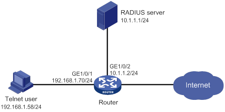
Configuration procedure
Make sure the settings on the router and the RADIUS server match.
1. Configure the router:
# Assign an IP address to GigabitEthernet 1/0/1 (the interface connected to the Telnet user).
<Router> system-view
[Router] interface gigabitethernet 1/0/1
[Router-GigabitEthernet1/0/1] ip address 192.168.1.70 255.255.255.0
[Router-GigabitEthernet1/0/1] quit
# Assign an IP address to GigabitEthernet 1/0/2 (the interface connected to the FreeRADIUS server).
[Router] interface gigabitethernet 1/0/2
[Router-GigabitEthernet1/0/2] ip address 10.1.1.2 255.255.255.0
[Router-GigabitEthernet1/0/2] quit
# Enable Telnet server.
[Router] telnet server enable
# Enable scheme authentication on the user lines for Telnet users.
[Router] line vty 0 63
[Router-line-vty0-63] authentication-mode scheme
[Router-line-vty0-63] quit
# Create a RADIUS scheme named rad and enter RADIUS scheme view.
[Router] radius scheme rad
# Specify the primary authentication and authorization server address and the service port in the scheme.
[Router-radius-rad] primary authentication 10.1.1.1 1812
# Set the shared key to expert in the scheme for the router to authenticate to the server.
[Router-radius-rad] key authentication simple expert
[Router-radius-rad] quit
# Configure the authentication, authorization, and accounting methods for login users in ISP domain bbb.
|
|
IMPORTANT: Because RADIUS user authorization information is piggybacked in authentication responses, the authentication and authorization methods must use the same RADIUS scheme. |
[Router] domain bbb
[Router-isp-bbb] authentication login radius-scheme rad
[Router-isp-bbb] authorization login radius-scheme rad
[Router-isp-bbb] accounting login none
[Router-isp-bbb] quit
# Create a feature group named fgroup1.
[Router] role feature-group name fgroup1
# Add the arp and radius features to the feature group.
[Router-featuregrp-fgroup1] feature arp
[Router-featuregrp-fgroup1] feature radius
[Router-featuregrp-fgroup1] quit
# Create a user role named role2.
[Router] role name role2
# Configure rule 1 to allow the user role to use all commands available in ISP view.
[Router-role-role2] rule 1 permit command system-view ; domain *
# Configure rule 2 to permit the user role to use the read and write commands of all features in fgroup1.
[Router-role-role2] rule 2 permit read write feature-group fgroup1
# Configure rule 3 to permit the user role to create VLANs and use all commands available in VLAN view.
[Router-role-role2] rule 3 permit command system-view ; vlan *
# Configure rule 4 to permit the user role to enter interface view and use all commands available in interface view.
[Router-role-role2] rule 4 permit command system-view ; interface *
# Configure the user role VLAN policy to disable configuration of all VLANs except for VLANs 1 to 20.
[Router-role-role2] vlan policy deny
[Router-role-role2-vlanpolicy] permit vlan 1 to 20
[Router-role-role2-vlanpolicy] quit
# Configure the user role interface policy to disable access to all interfaces except for GigabitEthernet 1/0/1 to GigabitEthernet 1/0/4.
[Router-role-role2] interface policy deny
[Router-role-role2-ifpolicy] permit interface gigabitethernet 1/0/1 to gigabitethernet 1/0/4
[Router-role-role2-ifpolicy] quit
[Router-role-role2] quit
2. Configure the RADIUS server:
# Add either of the user role attributes to the dictionary file of the FreeRADIUS server.
Cisco-AVPair = "shell:roles=\"role1 role2\""
Cisco-AVPair = "shell:roles*\"role1 role2\""
# Configure the settings required for the FreeRADIUS server to communicate with the router. (Details not shown.)
Verifying the configuration
# Telnet to the router, and enter the username and password to access the router. (Details not shown.)
# Verify that you can use all commands available in ISP view.
[Router] domain abc
[Router-isp-abc] authentication login radius-scheme abc
[Router-isp-abc] quit
# Verify that you can use all read and write commands of the radius and arp features. This example uses radius.
[Router] radius scheme rad
[Router-radius-rad] primary authentication 2.2.2.2
[Router-radius-rad] display radius scheme rad
…
Output of the RADIUS scheme is omitted.
# Verify that you cannot configure any VLANs except for VLANs 1 to 20. This example uses VLAN 10 and VLAN 30.
[Router] vlan 10
[Router-vlan10] quit
[Router] vlan 30
Permission denied.
# Verify that you cannot configure any interfaces except for GigabitEthernet 1/0/1 to GigabitEthernet 1/0/4. This example uses GigabitEthernet 1/0/2 and GigabitEthernet 1/0/5.
[Router] vlan 10
[Router-vlan10] port gigabitethernet 1/0/2
[Router-vlan10] port gigabitethernet 1/0/5
Permission denied.
RBAC temporary user role authorization configuration example (HWTACACS authentication)
Network requirements
As shown in Figure 4, the router uses local authentication for login users, including the Telnet user. The user account for the Telnet user is test@bbb and is assigned user role level-0.
Configure the remote-then-local authentication mode for temporary user role authorization. The router uses the HWTACACS server to provide authentication for changing the user role among level-0 through level-3 or changing the user role to network-admin. If the AAA configuration is invalid or the HWTACACS server does not respond, the router performs local authentication.
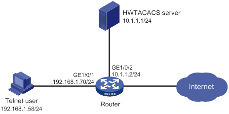
Configuration procedure
1. Configure the router:
# Assign an IP address to GigabitEthernet 1/0/1 (the interface connected to the Telnet user).
<Router> system-view
[Router] interface gigabitethernet 1/0/1
[Router-GigabitEthernet1/0/1] ip address 192.168.1.70 255.255.255.0
[Router-GigabitEthernet1/0/1] quit
# Assign an IP address to GigabitEthernet 1/0/2 (the interface connected to the HWTACACS server).
[Router] interface gigabitethernet 1/0/2
[Router-GigabitEthernet1/0/2] ip address 10.1.1.2 255.255.255.0
[Router-GigabitEthernet1/0/2] quit
# Enable Telnet server.
[Router] telnet server enable
# Enable scheme authentication on the user lines for Telnet users.
[Router] line vty 0 63
[Router-line-vty0-63] authentication-mode scheme
[Router-line-vty0-63] quit
# Enable remote-then-local authentication for temporary user role authorization.
[Router] super authentication-mode scheme local
# Create an HWTACACS scheme named hwtac and enter HWTACACS scheme view.
[Router] hwtacacs scheme hwtac
# Specify the primary authentication server address and the service port in the scheme.
[Router-hwtacacs-hwtac] primary authentication 10.1.1.1 49
# Set the shared key to expert in the scheme for the router to authenticate to the server.
[Router-hwtacacs-hwtac] key authentication simple expert
# Exclude ISP domain names from the usernames sent to the HWTACACS server.
[Router-hwtacacs-hwtac] user-name-format without-domain
[Router-hwtacacs-hwtac] quit
# Create an ISP domain named bbb and enter ISP domain view.
[Router] domain bbb
# Configure ISP domain bbb to use local authentication for login users.
[Router-isp-bbb] authentication login local
# Configure ISP domain bbb to use local authorization for login users.
[Router-isp-bbb] authorization login local
# Configure ISP domain bbb to not perform accounting for login users.
[Router-isp-bbb] accounting login none
# Apply HWTACACS scheme hwtac to the ISP domain for user role authentication.
[Router-isp-bbb] authentication super hwtacacs-scheme hwtac
[Router-isp-bbb] quit
# Create a device management user named test and enter local user view.
[Router] local-user test class manage
# Set the user service type to Telnet.
[Router-luser-manage-test] service-type telnet
# Set the user password to aabbcc.
[Router-luser-manage-test] password simple aabbcc
# Assign level-0 to the user.
[Router-luser-manage-test] authorization-attribute user-role level-0
# Remove the default user role (network-operator).
[Router-luser-manage-test] undo authorization-attribute user-role network-operator
[Router-luser-manage-test] quit
# Set the local authentication password to 654321 for user role level-3.
[Router] super password role level-3 simple 654321
# Set the local authentication password to 654321 for user role network-admin.
[Router] super password role network-admin simple 654321
[Router] quit
2. Configure the HWTACACS server:
This example uses ACSv4.0.
a. Access the User Setup page.
b. Add a user account named test. (Details not shown.)
c. In the Advanced TACACS+ Settings area, configure the following parameters:
- Select Level 3 for the Max Privilege for any AAA Client option.
If the target user role is only network-admin for temporary user role authorization, you can select any level for the option.
- Select the Use separate password option, and specify enabpass as the password.
Figure 5 Configuring advanced TACACS+ settings
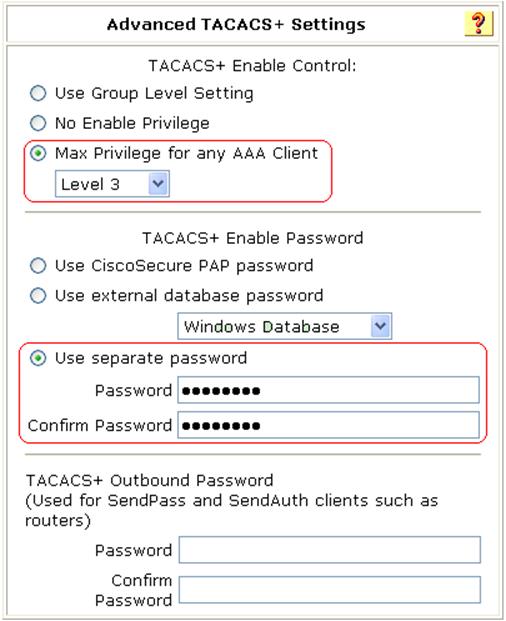
d. Select Shell (exec) and Custom attributes, and enter allowed-roles="network-admin" in the Custom attributes field.
Use a blank space to separate the allowed roles.
Figure 6 Configuring custom attributes for the Telnet user
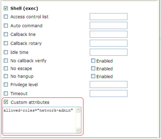
Verifying the configuration
1. Telnet to the router, and enter username test@bbb and password aabbcc to access the router. Verify that you have access to diagnostic commands.
<Router> telnet 192.168.1.70
Trying 192.168.1.70 ...
Press CTRL+K to abort
Connected to 192.168.1.59 ...
******************************************************************************
* Copyright (c) 2004-2017 New H3C Technologies Co., Ltd. All rights reserved.*
* Without the owner's prior written consent, *
* no decompiling or reverse-engineering shall be allowed. *
******************************************************************************
login: test@bbb
Password:
<Router>?
User view commands:
ping Ping function
quit Exit from current command view
ssh2 Establish a secure shell client connection
super Switch to a user role
system-view Enter the System View
telnet Establish a telnet connection
tracert Tracert function
<router>
2. Verify that you can obtain the level-3 user role:
# Use the super password to obtain the level-3 user role. When the system prompts for a username and password, enter username test@bbb and password enabpass.
<Router> super level-3
Username: test@bbb
Password:
The following output shows that you have obtained the level-3 user role.
User privilege role is level-3, and only those commands that authorized to the role can be used.
# If the ACS server does not respond, enter local authentication password 654321 at the prompt.
Invalid configuration or no response from the authentication server.
Change authentication mode to local.
Password:
User privilege role is level-3, and only those commands that authorized to the role can be used.
The output shows that you have obtained the level-3 user role.
3. Use the method in step 2 to verify that you can obtain the level-0, level-1, level-2, and network-admin user roles. (Details not shown.)
RBAC temporary user role authorization configuration example (RADIUS authentication)
Network requirements
As shown in Figure 7, the router uses local authentication for login users, including the Telnet user. The user account for the Telnet user is test@bbb and is assigned user role level-0.
Configure the remote-then-local authentication mode for temporary user role authorization. The router uses the RADIUS server to provide authentication for the network-admin user role. If the AAA configuration is invalid or the RADIUS server does not respond, the router performs local authentication.
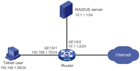
Configuration procedure
1. Configure the router:
# Assign an IP address to GigabitEthernet 1/0/1 (the interface connected to the Telnet user).
<Router> system-view
[Router] interface gigabitethernet 1/0/1
[Router-GigabitEthernet1/0/1] ip address 192.168.1.70 255.255.255.0
[Router-GigabitEthernet1/0/1] quit
# Assign an IP address to GigabitEthernet 1/0/2 (the interface connected to the RADIUS server).
[Router] interface gigabitethernet 1/0/2
[Router-GigabitEthernet1/0/2] ip address 10.1.1.2 255.255.255.0
[Router-GigabitEthernet1/0/2] quit
# Enable Telnet server.
[Router] telnet server enable
# Enable scheme authentication on the user lines for Telnet users.
[Router] line vty 0 63
[Router-line-vty0-63] authentication-mode scheme
[Router-line-vty0-63] quit
# Enable remote-then-local authentication for temporary user role authorization.
[Router] super authentication-mode scheme local
# Create RADIUS scheme radius and enter RADIUS scheme view.
[Router] radius scheme radius
# Specify the primary authentication server address and set the shared key in the scheme for secure communication between the router and the server.
[Router-radius-radius] primary authentication 10.1.1.1 key simple expert
# Exclude ISP domain names from the usernames sent to the RADIUS server.
[Router-radius-radius] user-name-format without-domain
[Router-radius-radius] quit
# Create an ISP domain named bbb and enter ISP domain view.
[Router] domain bbb
# Configure ISP domain bbb to use local authentication for login users.
[Router-isp-bbb] authentication login local
# Configure ISP domain bbb to use local authorization for login users.
[Router-isp-bbb] authorization login local
# Configure ISP domain bbb to not perform accounting for login users.
[Router-isp-bbb] accounting login none
# Apply RADIUS scheme radius to the ISP domain for user role authentication.
[Router-isp-bbb] authentication super radius-scheme radius
[Router-isp-bbb] quit
# Create a device management user named test and enter local user view.
[Router] local-user test class manage
# Set the user service type to Telnet.
[Router-luser-manage-test] service-type telnet
# Set the user password to aabbcc.
[Router-luser-manage-test] password simple aabbcc
# Assign level-0 to the user.
[Router-luser-manage-test] authorization-attribute user-role level-0
# Remove the default user role (network-operator).
[Router-luser-manage-test] undo authorization-attribute user-role network-operator
[Router-luser-manage-test] quit
# Set the local authentication password to abcdef654321 for user role network-admin.
[Router] super password role network-admin simple abcdef654321
[Router] quit
2. Configure the RADIUS server:
This example uses ACSv4.2.
a. Add a user account named $enab0$ and set the password to 123456. (Details not shown.)
b. Access the Cisco IOS/PIX 6.x RADIUS Attributes page.
c. Configure the cisco-av-pair attribute, as shown in Figure 8.
Figure 8 Configuring the cisco-av-pair attribute
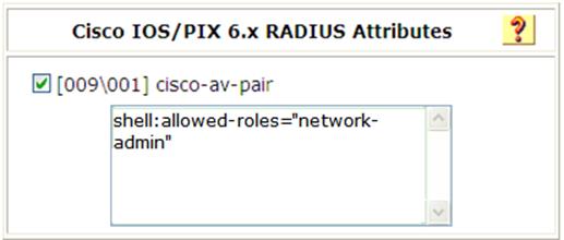
Verifying the configuration
1. Telnet to the router, and enter username test@bbb and password aabbcc to log in to the router. Verify that you have access to diagnostic commands.
<Router> telnet 192.168.1.70
Trying 192.168.1.70 ...
Press CTRL+K to abort
Connected to 192.168.1.59 ...
******************************************************************************
* Copyright (c) 2004-2017 New H3C Technologies Co., Ltd. All rights reserved.*
* Without the owner's prior written consent, *
* no decompiling or reverse-engineering shall be allowed. *
******************************************************************************
login: test@bbb
Password:
<Router>?
User view commands:
ping Ping function
quit Exit from current command view
ssh2 Establish a secure shell client connection
super Switch to a user role
system-view Enter the System View
telnet Establish a telnet connection
tracert Tracert function
<router>
2. Verify that you can obtain the network-admin user role:
# Use the super password to obtain the network-admin user role. When the system prompts for a username and password, enter username test@bbb and password 123456.
<Router> super network-admin
Username: test@bbb
Password:
The following output shows that you have obtained the network-admin user role:
User privilege role is network-admin, and only those commands that authorized to the role can be used.
# If the ACS server does not respond, enter local authentication password abcdef654321 at the prompt.
Invalid configuration or no response from the authentication server.
Change authentication mode to local.
Password:
User privilege role is network-admin, and only those commands that authorized to the role can be used.
The output shows that you have obtained the network-admin user role.
Troubleshooting RBAC
This section describes several typical RBAC issues and their solutions.
Local users have more access permissions than intended
Symptom
A local user can use more commands than should be permitted by the assigned user roles.
Analysis
The local user might have been assigned to user roles without your knowledge. For example, the local user is automatically assigned the default user role when you create the user.
Solution
To resolve the issue:
1. Use the display local-user command to examine the local user accounts for undesirable user roles, and remove them.
2. If the issue persists, contact H3C Support.
Login attempts by RADIUS users always fail
Symptom
Attempts by a RADIUS user to log in to the network access device always fail, even though the following conditions exist:
· The network access device and the RADIUS server can communicate with one another.
· All AAA settings are correct.
Analysis
RBAC requires that a login user have a minimum of one user role. If the RADIUS server does not authorize the login user to use any user roles, the user cannot log in to the device.
Solution
To resolve the issue:
1. Use one of the following methods:
? Configure the role default-role enable command. A RADIUS user can log in with the default user role when no user role is assigned by the RADIUS server.
? Add the user role authorization attributes on the RADIUS server.
2. If the issue persists, contact H3C Support.
Login overview
Login methods
The first time you access the device, you can only log in to the CLI through the console or AUX port. After login, you can change console login parameters or configure other access methods, including Telnet, SSH, and SNMP.
Table 10 Login methods at a glance
|
Login method |
Default settings and minimum configuration requirements |
Login configuration |
|
CLI login: |
|
|
|
· Local console or AUX login |
By default, console login and local AUX login are both enabled. Console login does not require authentication. Local AUX login requires password authentication but the password is null. The user role is network-admin for a console user and is network-operator for an AUX user. To improve device security, perform the following tasks immediately after you log in to the device for the first time: · Configure password or scheme authentication for the console line. · Configure a password or configure scheme authentication for the AUX line. |
|
|
· Telnet login |
By default, Telnet login is disabled. To enable Telnet login, perform the following tasks: · Enable the Telnet server feature. · Assign an IP address to a Layer 3 interface and make sure the interface and the Telnet client can reach each other. · Configure an authentication mode for VTY login users. By default, password authentication is used but no password is configured. · Assign a user role to VTY login users. By default, a VTY login user is assigned the network-operator user role. |
|
|
· SSH login |
By default, SSH login is disabled. To enable SSH login, perform the following tasks: · Enable the SSH server feature and configure SSH attributes. · Assign an IP address to a Layer 3 interface. Make sure the interface and the SSH client can reach each other. · Configure scheme authentication for VTY login users. By default, password authentication is used. · Assign a user role to VTY login users. By default, a VTY login user is assigned the network-operator user role. |
|
|
SNMP access |
By default, SNMP access is disabled. To enable SNMP access, perform the following tasks: · Assign an IP address to a Layer 3 interface. Make sure the interface and the NMS can reach each other. · Configure SNMP basic parameters. |
Feature and hardware compatibility
The following matrix shows the AUX port login and hardware compatibility:
|
Hardware |
AUX port login compatibility |
|
MSR810/810-W/810-W-DB/810-LM/810-W-LM/810-10-PoE/810-LM-HK/810-W-LM-HK/810-LMS/810-LUS |
No |
|
MSR2600-6-X1 |
No |
|
MSR2600-10-X1 |
Yes |
|
MSR 2630 |
Yes |
|
MSR3600-28/3600-51 |
Yes |
|
MSR3600-28-SI/3600-51-SI |
No |
|
MSR3610-X1/3610-X1-DP/3610-X1-DC/3610-X1-DP-DC |
No |
|
MSR 3610/3620/3620-DP/3640/3660 |
Yes |
|
MSR5620/5660/5680 |
Yes |
|
AUX port login compatibility |
|
|
MSR810-LM-GL |
No |
|
MSR810-W-LM-GL |
No |
|
MSR830-6EI-GL |
No |
|
MSR830-10EI-GL |
No |
|
MSR830-6HI-GL |
No |
|
MSR830-10HI-GL |
No |
|
MSR2600-6-X1-GL |
No |
|
MSR3600-28-SI-GL |
No |
FIPS compliance
The device supports the FIPS mode that complies with NIST FIPS 140-2 requirements. Support for features, commands, and parameters might differ in FIPS mode and non-FIPS mode. For more information about FIPS mode, see Security Configuration Guide.
Telnet is not supported in FIPS mode.
Using the console port for the first device access
The first time you access the device, you can log in to the CLI through the console port.
To log in through the console port, prepare a console terminal, for example, a PC. Make sure the console terminal has a terminal emulation program, such as HyperTerminal or PuTTY. For information about how to use terminal emulation programs, see the programs' user guides.
To log in through the console port:
1. Connect the DB-9 female connector of the console cable to the serial port of the PC.
2. Identify the console port of the device carefully and connect the RJ-45 connector of the console cable to the console port.
|
|
IMPORTANT: The serial ports on PCs do not support hot swapping. To connect a PC to an operating device, first connect the PC end. To disconnect a PC from an operating device, first disconnect the device end. |
Figure 9 Connecting a terminal to the console port
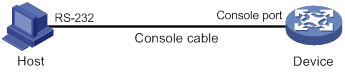
3. If the PC is off, turn on the PC.
4. On the PC, launch the terminal emulation program, and create a connection that uses the serial port connected to the device. Set the port properties so the port properties match the following console port default settings:
? Bits per second—9600 bps.
? Flow control—None.
? Parity—None.
? Stop bits—1.
? Data bits—8.
5. Power on the device and press Enter as prompted.
The default user view prompt <H3C> appears. You can enter commands to configure or manage the device. To get help, enter ?.
Configuring CLI login
By default, you can log in to the CLI through the console or AUX port. After you log in, you can configure other login methods, including Telnet and SSH.
To prevent illegal access to the CLI and control user behavior, perform the following tasks as required:
· Configure login authentication.
· Assign user roles.
· Configure command authorization and command accounting.
· Use ACLs to filter unauthorized logins.
This chapter describes how to configure and use CLI login methods, including login authentication, user roles, and common user line settings. For more information about command authorization, command accounting, and unauthorized access filtering, see "Controlling user access to the device."
CLI overview
User lines
The device uses user lines (also called user interfaces) to manage CLI sessions and monitor user behavior. For a user line, you can configure access control settings, including the login authentication method and user roles.
The device supports the user lines listed in Table 11. Different user lines require different login methods.
Table 11 CLI login method and user line matrix
|
User line |
Login method |
|
Console line |
Console port. |
|
AUX line |
AUX port. |
|
Virtual type terminal (VTY) line |
Telnet or SSH. |
User line numbering
Every user line has an absolute number and a relative number.
An absolute number uniquely identifies a user line among all user lines. The user lines are numbered starting from 0 and incrementing by 1, in the sequence of console, AUX, and VTY lines. You can use the display line command without any parameters to view supported user lines and their absolute numbers.
A relative number uniquely identifies a user line among all user lines of the same type. The number format is user line type + number. All types of user lines are numbered starting from 0 and incrementing by 1. For example, the first VTY line is VTY 0.
User line assignment
The device assigns user lines to CLI login users depending on their login methods, as shown in Table 11. When a user logs in, the device checks the idle user lines for the login method, and assigns the lowest numbered user line to the user. For example, four VTY lines (0 to 3) are configured, of which VTY 0 and VTY 3 are idle. When a user Telnets to the device, the device assigns VTY 0 to the user.
Each user line can be assigned only to one user at a time. If no user line is available, a CLI login attempt will be rejected.
Login authentication modes
You can configure login authentication to prevent illegal access to the device CLI.
In non-FIPS mode, the device supports the following login authentication modes:
· None—Disables authentication. This mode allows access without authentication and is insecure.
· Password—Requires password authentication. A user must provide the correct password at login.
· Scheme—Uses the AAA module to provide local or remote login authentication. A user must provide the correct username and password at login.
In FIPS mode, the device supports only the scheme authentication mode.
Different login authentication modes require different user line configurations, as shown in Table 12.
Table 12 Configuration required for different login authentication modes
|
Authentication mode |
Configuration tasks |
|
|
None |
Set the authentication mode to none. |
|
|
Password |
1. Set the authentication mode to password. 2. Set a password. |
|
|
Scheme |
1. Set the authentication mode to scheme. 2. Configure login authentication methods in ISP domain view. For more information, see Security Configuration Guide. |
|
User roles
A user is assigned user roles at login. The user roles control the commands available for the user. For more information about user roles, see "Configuring RBAC."
The device assigns user roles based on the login authentication mode and user type.
· In none or password authentication mode, the device assigns the user roles specified for the user line.
· In scheme authentication mode, the device uses the following rules to assign user roles:
? For an SSH login user who uses publickey or password-publickey authentication, the device assigns the user roles specified for the local device management user with the same name.
? For other users, the device assigns user roles according to the user role configuration of the AAA module. If the AAA server does not assign any user roles and the default user role feature is disabled, a remote AAA authentication user cannot log in.
Configuring local console or AUX login
You can connect a terminal to the console or AUX port of the device to log in and manage the device, as shown in Figure 10 and Figure 11. For the login procedure, see "Using the console port for the first device access."
Figure 10 Logging in through the console port

Figure 11 Logging in through the console or AUX port
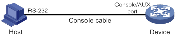
By default, console login and local AUX login are both enabled. Console login does not require authentication. Local AUX login requires password authentication but the password is null. The user role is network-admin for a console user and is network-operator for an AUX user. To improve device security, perform the following tasks immediately after you log in to the device for the first time:
· Configure password or scheme authentication for the console line.
· Configure a password or configure scheme authentication for the AUX line.
To configure console or AUX login, perform the following tasks:
|
Tasks at a glance |
Remarks |
|
(Required.) Perform one of the following tasks: · Disabling authentication for console or AUX login · Configuring password authentication for console or AUX login · Configuring scheme authentication for console or AUX login |
In FIPS mode, only the scheme authentication mode is supported. |
|
(Optional.) Configuring common console or AUX line settings |
N/A |
Console and AUX login configuration changes do not take effect for current online users. They take effect only for new login users.
Disabling authentication for console or AUX login
|
Step |
Command |
Remarks |
|
1. Enter system view. |
system-view |
N/A |
|
2. Enter console/AUX line view or class view. |
·
Enter console or AUX line view: ·
Enter console or AUX line class view: |
A setting in user line view applies only to the user line. A setting in user line class view applies to all user lines of the class. A non-default setting in either view takes precedence over a default setting in the other view. A non-default setting in user line view takes precedence over a non-default setting in user line class view. A setting in user line class view does not take effect for current online users. It takes effect only for new login users. |
|
3. Disable authentication. |
authentication-mode none |
In non-FIPS mode, authentication is disabled for the console line and password authentication is enabled for the AUX line by default. In FIPS mode, scheme authentication is enabled by default. |
|
4. Assign a user role. |
user-role role-name |
By default, a console line user is assigned the user role network-admin, and an AUX line user is assigned the user role network-operator. |
After you finish this configuration task, a user can log in through the console or AUX port without authentication.
Configuring password authentication for console or AUX login
|
Step |
Command |
Remarks |
|
1. Enter system view. |
system-view |
N/A |
|
2. Enter console/AUX line view or class view. |
·
Enter console or AUX line view: ·
Enter console or AUX line class view: |
A setting in user line view applies only to the user line. A setting in user line class view applies to all user lines of the class. A non-default setting in either view takes precedence over a default setting in the other view. A non-default setting in user line view takes precedence over a non-default setting in user line class view. A setting in user line class view does not take effect for current online users. It takes effect only for new login users. |
|
3. Enable password authentication. |
authentication-mode password |
In non-FIPS mode, authentication is disabled for the console line and password authentication is enabled for the AUX line by default. In FIPS mode, scheme authentication is enabled by default. |
|
4. Set a password. |
set authentication password { hash | simple } password |
By default, no password is set. |
|
5. Assign a user role. |
user-role role-name |
By default, a console line user is assigned the user role network-admin, and an AUX line user is assigned the user role network-operator. |
After you finish this configuration task, a user must provide the configured password when logging in through the console or AUX port.
Configuring scheme authentication for console or AUX login
|
Step |
Command |
Remarks |
|
1. Enter system view. |
system-view |
N/A |
|
2. Enter console/AUX line view or class view. |
·
Enter console or AUX line view: ·
Enter console or AUX line class view: |
A setting in user line view applies only to the user line. A setting in user line class view applies to all user lines of the class. A non-default setting in either view takes precedence over a default setting in the other view. A non-default setting in user line view takes precedence over a non-default setting in user line class view. A setting in user line class view does not take effect for current online users. It takes effect only for new login users. |
|
3. Enable scheme authentication. |
authentication-mode scheme |
In non-FIPS mode, authentication is disabled for the console line and password authentication is enabled for the AUX line by default. In FIPS mode, scheme authentication is enabled by default. |
To use scheme authentication, you must also perform the following tasks:
· Configure login authentication methods in ISP domain view.
· For remote authentication, configure a RADIUS, HWTACACS, or LDAP scheme.
· For local authentication, create a local user account and configure the relevant attributes.
For more information, see Security Configuration Guide.
After you finish this configuration task, a user must provide the configured username and password when logging in through the console or AUX port.
Configuring common console or AUX line settings
Some common settings for a console or AUX line take effect immediately and can interrupt the current session. Use a login method different from console or AUX login to log in to the device before you change console or AUX line settings.
After you change console or AUX line settings, adjust the settings on the configuration terminal or mobile terminal application accordingly for a successful login.
To configure common settings for a console or AUX line:
|
Step |
Command |
|
|
N/A |
||
|
2. Enter console/AUX line view or class view. |
·
Enter console or AUX line view: ·
Enter console or AUX line class view: |
A setting in user line view applies only to the user line. A setting in user line class view applies to all user lines of the class. A non-default setting in either view takes precedence over a default setting in the other view. A non-default setting in user line view takes precedence over a non-default setting in user line class view. A setting in user line class view does not take effect for current online users. It takes effect only for new login users. |
|
3. Set the transmission rate. |
speed speed-value |
By default, the transmission rate is 9600 bps. This command is not available in console or AUX line class view. |
|
4. Specify the parity. |
parity { even | mark | none | odd | space } |
By default, a user line does not use parity. This command is not available in console or AUX line class view. |
|
5. Specify the number of stop bits for a character. |
stopbits { 1 | 1.5 | 2 } |
The default is 1. Stop bits indicate the end of a character. The more the stop bits, the slower the transmission. This command is not available in console or AUX line class view. |
|
6. Specify the number of data bits for a character. |
databits { 5 | 6 | 7 | 8 } |
The default is 8. Configure this command depending on the character coding type. For example, set the number of data bits to 7 for standard ASCII characters. Set the number of data bits to 8 for extended ASCII characters. This command is not available in console or AUX line class view. |
|
7. Specify the terminal session activation key. |
activation-key character |
|
|
8. Specify the escape key. |
escape-key { character | default } |
|
|
9. Set the user line locking key. |
lock-key key-string |
By default, no user line locking key is set. |
|
10. Configure the flow control mode. |
flow-control { hardware | none | software } flow-control hardware direction1 [ software direction2 ] flow-control software direction1 [ hardware direction2 ] |
This command is not available in console or AUX line class view. |
|
11. Specify the terminal display type. |
terminal type { ansi | vt100 } |
By default, the terminal display type is ANSI. The device supports ANSI and VT100 terminal display types. As a best practice, specify VT100 type on both the device and the configuration terminal. If either side uses the ANSI type, a display problem might occur when a command line has more than 80 characters. For example, a cursor positioning error might occur. |
|
12. Set the maximum number of lines of command output to send to the terminal at a time. |
screen-length screen-length |
By default, the device sends up to 24 lines to the terminal at a time when pausing between screens of output is enabled. To disable pausing between screens of output, set the value to 0. |
|
13. Set the size for the command history buffer. |
history-command max-size value |
|
|
idle-timeout minutes [ seconds ] |
By default, the CLI connection idle-timeout timer is 10 minutes. If no interaction occurs between the device and the user within the idle-timeout interval, the system automatically terminates the user connection on the user line. If you set the timeout timer to 0, the connection will not be aged out. |
|
|
15. Specify the command to be automatically executed for login users on the lines. |
auto-execute command command |
By default, no command is specified for a user line to be automatically executed. The device will automatically execute the specified command when a user logs in through the user line, and close the user connection after the command is executed. This command is not available in console line view or console line class view. |
|
16. Enable the terminal service. |
shell |
Be default, the terminal service is enabled on all user lines. The undo shell command is not available in console line view or console line class view. |
Configuring Telnet login
The device can act as a Telnet server to allow Telnet login, or as a Telnet client to Telnet to other devices.
By default, Telnet login is disabled on the device. To configure Telnet login, you must first log in to the device through any other method.
|
|
NOTE: Telnet login is not supported in FIPS mode. |
Configuring the device as a Telnet server
|
Tasks at a glance |
|
(Required.) Enabling Telnet server |
|
(Required.) Perform one of the following tasks: · Disabling authentication for Telnet login |
|
(Optional.) Configuring common Telnet server settings |
|
(Optional.) Configuring common VTY line settings |
Telnet login configuration changes do not take effect for current online users. They take effect only for new login users.
Enabling Telnet server
|
Step |
Command |
Remarks |
|
1. Enter system view. |
system-view |
N/A |
|
2. Enable the Telnet server. |
telnet server enable |
By default, the Telnet server is disabled. |
Disabling authentication for Telnet login
|
Step |
Command |
Remarks |
|
1. Enter system view. |
system-view |
N/A |
|
2. Enter VTY line view or class view. |
·
Enter VTY line view: ·
Enter VTY line class view: |
A setting in user line view applies only to the user line. A setting in user line class view applies to all user lines of the class. A non-default setting in either view takes precedence over a default setting in the other view. A non-default setting in user line view takes precedence over a non-default setting in user line class view. A setting in user line class view does not take effect for current online users. It takes effect only for new login users. |
|
3. Disable authentication. |
authentication-mode none |
In non-FIPS mode, password authentication is enabled for VTY lines by default. In VTY line view, this command is associated with the protocol inbound command. If you specify a non-default value for one of the two commands, the other command uses the default setting, regardless of the setting in VTY line class view. |
|
4. (Optional.) Assign a user role. |
user-role role-name |
By default, a VTY line user is assigned the user role network-operator. |
Configuring password authentication for Telnet login
|
Step |
Command |
Remarks |
|
1. Enter system view. |
system-view |
N/A |
|
2. Enter VTY line view or class view. |
·
Enter VTY line view: ·
Enter VTY line class view: |
A setting in user line view applies only to the user line. A setting in user line class view applies to all user lines of the class. A non-default setting in either view takes precedence over a default setting in the other view. A non-default setting in user line view takes precedence over a non-default setting in user line class view. A setting in user line class view does not take effect for current online users. It takes effect only for new login users. |
|
3. Enable password authentication. |
authentication-mode password |
In non-FIPS mode, password authentication is enabled for VTY lines by default. In VTY line view, this command is associated with the protocol inbound command. If you specify a non-default value for one of the two commands, the other command uses the default setting, regardless of the setting in VTY line class view. |
|
4. Set a password. |
set authentication password { hash | simple } password |
By default, no password is set. |
|
5. (Optional.) Assign a user role. |
user-role role-name |
By default, a VTY line user is assigned the user role network-operator. |
Configuring scheme authentication for Telnet login
|
Step |
Command |
Remarks |
|
1. Enter system view. |
system-view |
N/A |
|
2. Enter VTY line view or class view. |
·
Enter VTY line view: ·
Enter VTY line class view: |
A setting in user line view applies only to the user line. A setting in user line class view applies to all user lines of the class. A non-default setting in either view takes precedence over a default setting in the other view. A non-default setting in user line view takes precedence over a non-default setting in user line class view. A setting in user line class view does not take effect for current online users. It takes effect only for new login users. |
|
3. Enable scheme authentication. |
authentication-mode scheme |
In non-FIPS mode, password authentication is enabled for VTY lines by default. In VTY line view, this command is associated with the protocol inbound command. If you specify a non-default value for one of the two commands, the other command uses the default setting, regardless of the setting in VTY line class view. |
To use scheme authentication, you must also perform the following tasks:
· Configure login authentication methods in ISP domain view.
· For remote authentication, configure a RADIUS, HWTACACS, or LDAP scheme.
· For local authentication, create a local user account and configure the relevant attributes.
For more information, see Security Configuration Guide.
Configuring common Telnet server settings
|
Step |
Command |
Remarks |
|
1. Enter system view. |
system-view |
N/A |
|
2. Specify the Telnet service port number. |
·
In an IPv4 network: ·
In an IPv6 network: |
By default, the Telnet service port number is 23. |
|
3. Set the DSCP value for outgoing Telnet packets. |
·
For a Telnet server running IPv4: ·
For a Telnet server running IPv6: |
By default, the DSCP value is 48. The DSCP value is carried in the ToS/Traffic class field of an IP or IPv6 packet to indicate the transmission priority of the packet. |
|
4. Set the maximum number of concurrent Telnet users. |
aaa session-limit telnet max-sessions |
The default is 32. Changing this setting does not affect users who are currently online. If the new limit is less than the number of online Telnet users, no additional users can Telnet in until the number drops below the new limit. For more information about this command, see Security Command Reference. |
Configuring common VTY line settings
For a VTY line, you can specify a command that is to be automatically executed when a user logs in. After executing the specified command, the system automatically disconnects the Telnet session. Typically, you configure the auto-execute command telnet X.X.X.X command on the device so the device redirects a Telnet user to the host at X.X.X.X. The connection to the current device is closed when the user terminates the Telnet connection to X.X.X.X.
To configure common settings for VTY lines:
|
Step |
Command |
Remarks |
|
1. Enter system view. |
system-view |
N/A |
|
2. Enter VTY line view or class view. |
·
Enter VTY line view: ·
Enter VTY line class view: |
A setting in user line view applies only to the user line. A setting in user line class view applies to all user lines of the class. A non-default setting in either view takes precedence over a default setting in the other view. A non-default setting in user line view takes precedence over a non-default setting in user line class view. A setting in user line class view does not take effect for current online users. It takes effect only for new login users. |
|
3. Enable the terminal service. |
shell |
By default, the terminal service is enabled on all user lines. |
|
4. Specify the supported protocols. |
protocol inbound { all | pad | ssh | telnet } |
By default, Telnet and SSH are supported. A protocol change does not take effect for current online users. It takes effect only for new login users. In VTY line view, this command is associated with the authentication-mode command. If you specify a non-default value for one of the two commands, the other command uses the default setting, regardless of the setting in VTY line class view. |
|
5. Specify the shortcut key for terminating a task. |
escape-key { character | default } |
The default setting is Ctrl+C. |
|
6. Set the user line locking key. |
lock-key key-string |
By default, no user line locking key is set. |
|
7. Specify the terminal display type. |
terminal type { ansi | vt100 } |
The default terminal display type is ANSI. |
|
8. Set the maximum number of lines of command output to send to the terminal at a time. |
screen-length screen-length |
By default, the device sends up to 24 lines to the terminal at a time when pausing between screens of output is enabled. To disable pausing between screens of output, set the value to 0. |
|
9. Set the size for the command history buffer. |
history-command max-size value |
The default size is 10 history commands. |
|
10. Set the CLI connection idle-timeout timer. |
idle-timeout minutes [ seconds ] |
By default, the CLI connection idle-timeout timer is 10 minutes. If no interaction occurs between the device and the user within the idle-timeout interval, the system automatically terminates the user connection on the user line. If you set the timeout timer to 0, the connection will not be aged out. |
|
11. Specify the command to be automatically executed for login users on the user lines. |
auto-execute command command |
By default, no command is specified for auto execution.
Before you configure this command and save the configuration, make sure you can access the CLI through a different user line. |
Using the device to log in to a Telnet server
You can use the device as a Telnet client to log in to a Telnet server. If the server is located in a different subnet than the client, make sure the two devices can reach each other.
Figure 12 Telnetting from the device to a Telnet server
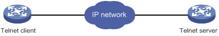
To use the device to log in to a Telnet server:
|
Step |
Command |
Remarks |
|
1. Enter system view. |
system-view |
N/A |
|
2. (Optional.) Specify the source IPv4 address or source interface for outgoing Telnet packets. |
telnet client source { interface interface-type interface-number | ip ip-address } |
By default, no source IPv4 address or source interface is specified. The device uses the primary IPv4 address of the output interface as the source address for outgoing Telnet packets. |
|
3. Exit to user view. |
quit |
N/A |
|
4. Use the device to log in to a Telnet server. |
·
Log in to an IPv4 Telnet server: ·
Log in to an IPv6 Telnet server: |
N/A |
Configuring SSH login
SSH offers a secure method to remote login. By providing encryption and strong authentication, it protects devices against attacks such as IP spoofing and plaintext password interception. For more information, see Security Configuration Guide.
The device can act as an SSH server to allow Telnet login, or as an SSH client to log in to an SSH server.
By default, SSH login is disabled on the device. To configure SSH login, you must first log in to the device through any other method.
Configuring the device as an SSH server
This section provides the SSH server configuration procedure used when the SSH client authentication method is password. For more information about SSH and publickey authentication configuration, see Security Configuration Guide.
To configure the device as an SSH server:
|
Step |
Command |
Remarks |
|
|
1. Enter system view. |
system-view |
N/A |
|
|
2. Create local key pairs. |
·
In non-FIPS mode: ·
In FIPS mode: |
By default, no local key pairs are created. |
|
|
3. Enable the Stelnet server. |
ssh server enable |
By default, the Stelnet server is disabled. |
|
|
4. (Optional.) Create an SSH user and specify the authentication mode. |
·
In non-FIPS mode: ·
In FIPS mode: |
By default, no SSH user is configured on the device. |
|
|
5. Enter VTY line view or class view. |
·
Enter VTY line view: ·
Enter VTY line class view: |
A setting in user line view applies only to the user line. A setting in user line class view applies to all user lines of the class. A non-default setting in either view takes precedence over a default setting in the other view. A non-default setting in user line view takes precedence over a non-default setting in user line class view. A setting in user line class view does not take effect for current online users. It takes effect only for new login users. |
|
|
6. Enable scheme authentication. |
authentication-mode scheme |
In non-FIPS mode, password authentication is enabled for VTY lines by default. In FIPS mode, scheme authentication is enabled for VTY lines by default. In VTY line view, this command is associated with the protocol inbound command. If you specify a non-default value for one of the two commands, the other command uses the default setting, regardless of the setting in VTY line class view. |
|
|
7. (Optional.) Specify the protocols for the user lines to support. |
·
In non-FIPS mode: ·
In FIPS mode: |
In non-FIPS mode, Telnet and SSH are supported by default. In FIPS mode, SSH is supported by default. A protocol change does not take effect for current online users. It takes effect only for new login users. In VTY line view, this command is associated with the authentication-mode command. If you specify a non-default value for one of the two commands, the other command uses the default setting, regardless of the setting in VTY line class view. |
|
|
8. Exit to system view. |
quit |
N/A |
|
|
9. (Optional.) Configure common settings for VTY lines. |
N/A |
|
|
|
10. (Optional.) Set the maximum number of concurrent SSH users. |
aaa session-limit ssh max-sessions |
The default is 32. Changing this setting does not affect users who are currently online. If the new limit is less than the number of online SSH users, no additional SSH users can log in until the number drops below the new limit. For more information about this command, see Security Command Reference. |
|
Using the device to log in to an SSH server
You can use the device as an SSH client to log in to an SSH server. If the server is located in a different subnet than the client, make sure the two devices can reach each other.
Figure 13 Logging in to an SSH server from the device
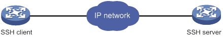
Perform the following tasks in user view:
|
Task |
Command |
|
Log in to an IPv4 SSH server. |
ssh2 server |
|
Log in to an IPv6 SSH server. |
ssh2 ipv6 server |
To work with the SSH server, you might need to specify a set of parameters. For more information, see Security Configuration Guide.
Displaying and maintaining CLI login
Execute display commands in any view.
|
Task |
Command |
Remarks |
|
Display online CLI users. |
display users [ all ] |
N/A |
|
Display user line information. |
display line [ num1 | { aux | console | vty } num2 ] [ summary ] |
N/A |
|
Display the packet source setting for the Telnet client. |
display telnet client |
N/A |
|
Release a user line. |
free line { num1 | { aux | console | vty } num2 } |
Multiple users can log in to the device to simultaneously configure the device. When necessary, you can execute this command to release some connections. You cannot use this command to release the connection you are using This command is available in user view. |
|
Lock the current user line and set the password for unlocking the line. |
lock |
By default, the system does not lock any user lines. This command is not supported in FIPS mode. This command is available in user view. |
|
Lock the current user line and enable unlocking authentication. |
lock reauthentication |
By default, the system does not lock any user lines or initiate reauthentication. To unlock the locked user line, you must press Enter and provide the login password to pass reauthentication. This command is available in any view. |
|
Send messages to user lines. |
send { all | num1 | { aux | console | vty } num2 } |
This command is available in user view. |
Accessing the device through SNMP
You can run SNMP on an NMS to access the device MIB and perform Get and Set operations to manage and monitor the device.
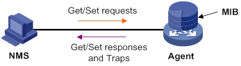
The device supports SNMPv1, SNMPv2c, and SNMPv3, and can cooperate with various network management software products. However, the device and the NMS must use the same SNMP version.
By default, SNMP access is disabled. To configure SNMP access, you must first log in to the device through any other method.
For more information about SNMP, see Network Management and Monitoring Configuration Guide.
Controlling user access to the device
Use ACLs to prevent unauthorized access, and configure command authorization and accounting to monitor and control user behavior. For more information about ACLs, see ACL and QoS Configuration Guide.
Feature and hardware compatibility
|
Hardware |
AUX port login compatibility |
|
MSR810/810-W/810-W-DB/810-LM/810-W-LM/810-10-PoE/810-LM-HK/810-W-LM-HK/810-LMS/810-LUS |
No |
|
MSR2600-6-X1 |
No |
|
MSR2600-10-X1 |
Yes |
|
MSR 2630 |
Yes |
|
MSR3600-28/3600-51 |
Yes |
|
MSR3600-28-SI/3600-51-SI |
No |
|
MSR3610-X1/3610-X1-DP/3610-X1-DC/3610-X1-DP-DC |
No |
|
MSR 3610/3620/3620-DP/3640/3660 |
Yes |
|
MSR5620/5660/5680 |
Yes |
|
Hardware |
AUX port login compatibility |
|
MSR810-LM-GL |
No |
|
MSR810-W-LM-GL |
No |
|
MSR830-6EI-GL |
No |
|
MSR830-10EI-GL |
No |
|
MSR830-6HI-GL |
No |
|
MSR830-10HI-GL |
No |
|
MSR2600-6-X1-GL |
No |
|
MSR3600-28-SI-GL |
No |
Controlling Telnet and SSH logins
Use different types of ACLs to filter Telnet and SSH logins by different match criteria:
· Basic ACL (2000 to 2999)—Source IP address.
· Advanced ACL (3000 to 3999)—Source IP address and destination IP address.
· Ethernet frame header ACL (4000 to 4999)—Source MAC address.
If an applied ACL does not exist or does not have any rules, no user login restriction is applied. If the ACL exists and has rules, only users permitted by the ACL can access the device through Telnet or SSH.
Configuration procedures
|
Step |
Command |
Remarks |
|
1. Enter system view. |
system-view |
N/A |
|
2. Apply an ACL to filter Telnet logins. |
· telnet server acl acl-number · telnet server ipv6 acl [ ipv6 ] acl-number |
By default, no ACL is used to filter Telnet logins. |
|
3. (Optional.) Enable logging for Telnet login attempts that are denied by Telnet login control ACLs. |
telnet server acl-deny-log enable |
By default, logging is disabled for Telnet login attempts that are denied by Telnet login control ACLs. |
To control SSH logins:
|
Step |
Command |
Remarks |
|
1. Enter system view. |
system-view |
N/A |
|
2. Apply an ACL to filter SSH logins. |
· ssh server acl acl-number · ssh server ipv6 acl [ ipv6 ] acl-number |
By default, no ACL is used to filter SSH logins. For more information about these two commands, see Security Command Reference. |
|
3. (Optional.) Enable logging for SSH login attempts that are denied by SSH login control ACLs. |
ssh server acl-deny-log enable |
By default, logging is disabled for SSH login attempts that are denied by SSH login control ACLs. For more information about ssh commands, see Security Command Reference. |
Configuration example
Network requirements
As shown in Figure 15, the device is a Telnet server.
Configure the device to permit only Telnet packets sourced from Host A and Host B.
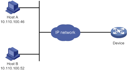
Configuration procedure
# Configure an ACL to permit packets sourced from Host A and Host B.
<Sysname> system-view
[Sysname] acl basic 2000 match-order config
[Sysname-acl-ipv4-basic-2000] rule 1 permit source 10.110.100.52 0
[Sysname-acl-ipv4-basic-2000] rule 2 permit source 10.110.100.46 0
[Sysname-acl-ipv4-basic-2000] quit
# Apply the ACL to filter Telnet logins.
[Sysname] telnet server acl 2000
Controlling SNMP access
Use a basic ACL (2000 to 2999) to control SNMP access by source IP address. To access the requested MIB view, an NMS must use a source IP address permitted by the ACL. If the ACL does not exist or does not have any rules, no user login restriction is applied.
Configuration procedure
To control SNMPv1 or SNMPv2c access:
|
Step |
Command |
Remarks |
|
1. Enter system view. |
system-view |
N/A |
|
2. Configure the SNMP access right. |
· (Method 1.) Create an SNMP community and specify ACLs for the community: ? In VACM mode: · (Method 2.) Create an SNMPv1/v2c group and add a user to the group, specifying ACLs for the group and user: a. snmp-agent group { v1 | v2c } group-name [ read-view view-name ] [ write-view view-name ] [ notify-view view-name ] [ acl { ipv4-acl-number | name ipv4-acl-name } | acl ipv6 { ipv6-acl-number | name ipv6-acl-name } ] * b. snmp-agent usm-user { v1 | v2c } user-name group-name [ acl { ipv4-acl-number | name ipv4-acl-name } | acl ipv6 { ipv6-acl-number | name ipv6-acl-name } ] * |
For more information about SNMP, see Network Management and Monitoring Configuration Guide. |
To control SNMPv3 access:
|
Step |
Command |
Remarks |
|
1. Enter system view. |
system-view |
N/A |
|
2. Create an SNMPv3 group, specifying ACLs for the group. |
·
In non-FIPS mode: ·
In FIPS mode: |
N/A |
|
3. Create an SNMPv3 user, specifying ACLs for the user. |
In non-FIPS mode: ·
In VACM mode: ·
In RBAC mode: In FIPS mode: ·
In VACM mode: ·
In RBAC mode: |
For more information about SNMP, see Network Management and Monitoring Configuration Guide. |
Configuration example
Network requirements
As shown in Figure 16, the device is running SNMP.
Configure the device to allow Host A and Host B to access the device through SNMP.
Configuration procedure
# Create an ACL to permit packets sourced from Host A and Host B.
<Sysname> system-view
[Sysname] acl basic 2000 match-order config
[Sysname-acl-ipv4-basic-2000] rule 1 permit source 10.110.100.52 0
[Sysname-acl-ipv4-basic-2000] rule 2 permit source 10.110.100.46 0
[Sysname-acl-ipv4-basic-2000] quit
# Associate the ACL with the SNMP community and the SNMP group.
[Sysname] snmp-agent community read aaa acl 2000
[Sysname] snmp-agent group v2c groupa acl 2000
[Sysname] snmp-agent usm-user v2c usera groupa acl 2000
Configuring command authorization
By default, commands available for a user depend only on the user's user roles. When the authentication mode is scheme, you can configure the command authorization feature to further control access to commands.
After you enable command authorization, a user can use only commands that are permitted by both the AAA scheme and user roles.
The command authorization method can be different from the user login authorization method.
This section provides the procedure for configuring command authorization. To make the command authorization feature take effect, you must configure a command authorization method in ISP domain view. For more information, see Security Configuration Guide.
Configuration procedure
To configure command authorization:
|
Step |
Command |
Remarks |
|
1. Enter system view. |
system-view |
N/A |
|
2. Enter user line view or user line class view. |
·
Enter user line view: ·
Enter user line class view: |
A setting in user line view applies only to the user line. A setting in user line class view applies to all user lines of the class. A non-default setting in either view takes precedence over a default setting in the other view. A non-default setting in user line view takes precedence over a non-default setting in user line class view. A setting in user line class view does not take effect for current online users. It takes effect only for new login users. |
|
3. Enable scheme authentication. |
authentication-mode scheme |
In non-FIPS mode, authentication is disabled for console lines, and password authentication is enabled for AUX and VTY lines by default. In FIPS mode, scheme authentication is enabled by default. In VTY line view, this command is associated with the protocol inbound command. If you specify a non-default value for one of the two commands, the other command uses the default setting, regardless of the setting in VTY line class view. |
|
4. Enable command authorization. |
command authorization |
By default, command authorization is disabled, and the commands available for a user only depend on the user role. If the command authorization command is configured in user line class view, command authorization is enabled on all user lines in the class. You cannot configure the undo command authorization command in the view of a user line in the class. |
Configuration example
Network requirements
As shown in Figure 17, Host A needs to log in to the device to manage the device.
Configure the device to perform the following operations:
· Allow Host A to Telnet in after authentication.
· Use the HWTACACS server to control the commands that the user can execute.
· If the HWTACACS server is not available, use local authorization.
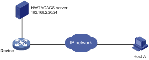
Configuration procedure
# Assign IP addresses to relevant interfaces. Make sure the device and the HWTACACS server can reach each other. Make sure the device and Host A can reach each other. (Details not shown.)
# Enable the Telnet server.
<Device> system-view
[Device] telnet server enable
# Enable scheme authentication for user lines VTY 0 through VTY 63.
[Device] line vty 0 63
[Device-line-vty0-63] authentication-mode scheme
# Enable command authorization for the user lines.
[Device-line-vty0-63] command authorization
[Device-line-vty0-63] quit
# Create HWTACACS scheme tac.
[Device] hwtacacs scheme tac
# Configure the scheme to use the HWTACACS server at 192.168.2.20:49 for authentication and authorization.
[Device-hwtacacs-tac] primary authentication 192.168.2.20 49
[Device-hwtacacs-tac] primary authorization 192.168.2.20 49
# Set the shared keys to expert.
[Device-hwtacacs-tac] key authentication simple expert
[Device-hwtacacs-tac] key authorization simple expert
# Remove domain names from usernames sent to the HWTACACS server.
[Device-hwtacacs-tac] user-name-format without-domain
[Device-hwtacacs-tac] quit
# Configure the system-defined domain system.
[Device] domain system
# Use HWTACACS scheme tac for login user authentication and command authorization. Use local authentication and local authorization as the backup method.
[Device-isp-system] authentication login hwtacacs-scheme tac local
[Device-isp-system] authorization command hwtacacs-scheme tac local
[Device-isp-system] quit
# Create the local user monitor. Set the simple password to 123, the service type to Telnet, and the default user role to level-1.
[Device] local-user monitor
[Device-luser-manage-monitor] password simple 123
[Device-luser-manage-monitor] service-type telnet
[Device-luser-manage-monitor] authorization-attribute user-role level-1
Configuring command accounting
Command accounting uses the HWTACACS server to record all executed commands to monitor user behavior on the device.
If command accounting is enabled but command authorization is not, every executed command is recorded. If both command accounting and command authorization are enabled, only authorized commands that are executed are recorded.
The command accounting method can be the same as or different from the command authorization method and user login authorization method.
This section provides only the procedure for configuring command accounting. To make the command accounting feature take effect, you must configure a command accounting method in ISP domain view. For more information, see Security Configuration Guide.
Configuration procedure
To configure command accounting:
|
Step |
Command |
Remarks |
|
1. Enter system view. |
system-view |
N/A |
|
2. Enter user line view or user line class view. |
·
Enter user line view: ·
Enter user line class view: |
A setting in user line view applies only to the user line. A setting in user line class view applies to all user lines of the class. A non-default setting in either view takes precedence over a default setting in the other view. A non-default setting in user line view takes precedence over a non-default setting in user line class view. A setting in user line class view does not take effect for current online users. It takes effect only for new login users. |
|
3. Enable scheme authentication. |
authentication-mode scheme |
In non-FIPS mode, authentication is disabled for console lines, and password authentication is enabled for AUX and VTY lines by default. In FIPS mode, scheme authentication is enabled by default. In VTY line view, this command is associated with the protocol inbound command. If you specify a non-default value for one of the two commands, the other command uses the default setting, regardless of the setting in VTY line class view. |
|
4. Enable command accounting. |
command accounting |
By default, command accounting is disabled. The accounting server does not record the commands executed by users. If the command accounting command is configured in user line class view, command accounting is enabled on all user lines in the class. You cannot configure the undo command accounting command in the view of a user line in the class. |
Configuration example
Network requirements
As shown in Figure 18, users need to log in to the device to manage the device.
Configure the device to send commands executed by users to the HWTACACS server to monitor and control user operations on the device.
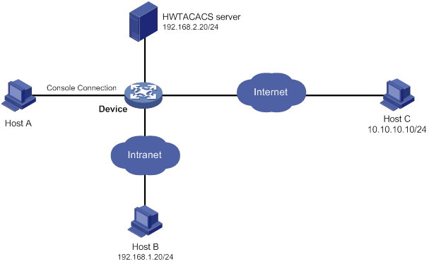
Configuration procedure
# Enable the Telnet server.
<Device> system-view
[Device] telnet server enable
# Create HWTACACS scheme tac.
[Device] hwtacacs scheme tac
# Configure the scheme to use the HWTACACS server at 192.168.2.20:49 for accounting.
[Device-hwtacacs-tac] primary accounting 192.168.2.20 49
# Set the shared key to expert.
[Device-hwtacacs-tac] key accounting simple expert
# Remove domain names from usernames sent to the HWTACACS server.
[Device-hwtacacs-tac] user-name-format without-domain
[Device-hwtacacs-tac] quit
# Configure the system-defined domain system to use the HWTACACS scheme for command accounting.
[Device] domain system
[Device-isp-system] accounting command hwtacacs-scheme tac
[Device-isp-system] quit
# Enable command accounting for user line Console 0.
[Device] line console 0
[Device-line-console0] command accounting
[Device-line-console0] quit
# Enable command accounting for user lines VTY 0 through VTY 63.
[Device] line vty 0 63
[Device-line-vty0-63] command accounting
[Device-line-vty0-63] quit
Configuring FTP
Overview
File Transfer Protocol (FTP) is an application layer protocol for transferring files from one host to another over an IP network, as shown in Figure 19. It uses TCP port 20 to transfer data and TCP port 21 to transfer control commands. For more information about FTP, see RFC 959.
FTP is based on the client/server model. The device can act as the FTP server or FTP client. Make sure the FTP server and the FTP client can reach each other before establishing the FTP connection.
Figure 19 FTP application scenario
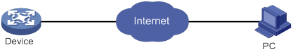
FTP supports the following transfer modes:
· Binary mode—Used to non-text files, such as .app, .bin, and .btm files.
· ASCII mode—Used to transfer text files, such as .txt, .bat, and .cfg files.
When the device acts as the FTP client, you can set the transfer mode (binary by default). When the device acts as the FTP server, the transfer mode is determined by the FTP client.
FTP can operate in either of the following modes:
· Active mode (PORT)—The FTP server initiates the TCP connection. This mode is not suitable when the FTP client is behind a firewall, for example, when the FTP client resides in a private network.
· Passive mode (PASV)—The FTP client initiates the TCP connection. This mode is not suitable when the server does not allow the client to use a random unprivileged port greater than 1024.
FTP operation mode varies depending on the FTP client program.
Command and hardware compatibility
Commands and descriptions for centralized devices apply to the following routers:
· MSR810/810-W/810-W-DB/810-LM/810-W-LM/810-10-PoE/810-LM-HK/810-W-LM-HK/810-LMS/810-LUS.
· MSR2600-6-X1/2600-10-X1.
· MSR 2630.
· MSR3600-28/3600-51.
· MSR3600-28-SI/3600-51-SI.
· MSR3610-X1/3610-X1-DP/3610-X1-DC/3610-X1-DP-DC.
· MSR 3610/3620/3620-DP/3640/3660.
· MSR810-LM-GL/810-W-LM-GL/830-6EI-GL/830-10EI-GL/830-6HI-GL/830-10HI-GL/2600-6-X1-GL/3600-28-SI-GL.
Commands and descriptions for distributed devices apply to the following routers:
· MSR5620.
· MSR 5660.
· MSR 5680.
FIPS compliance
The device supports the FIPS mode that complies with NIST FIPS 140-2 requirements. Support for features, commands, and parameters might differ in FIPS mode and non-FIPS mode. For more information about FIPS mode, see Security Configuration Guide.
FTP is not supported in FIPS mode.
Using the device as an FTP server
To use the device as an FTP server, you must enable the FTP server and configure authentication and authorization on the device. Other commands are optional.
Configuring basic parameters
|
Step |
Command |
Remarks |
|
1. Enter system view. |
system-view |
N/A |
|
2. Enable the FTP server. |
ftp server enable |
By default, the FTP server is disabled. |
|
3. (Optional.) Use an ACL to control access to the FTP server. |
·
For IPv4 FTP clients: ·
For IPv6 FTP clients: |
By default, no ACL is used for access control. |
|
4. (Optional.) Enable logging for FTP login attempts that are denied by FTP login control ACLs. |
ftp server acl-deny-log enable |
By default, logging is disabled for FTP login attempts that are denied by FTP login control ACLs. |
|
5. (Optional.) Associate an SSL server policy with the FTP server to ensure data security. |
ftp server ssl-server-policy policy-name |
By default, no SSL server policy is associated with the FTP server. |
|
ftp timeout minutes |
By default, the FTP connection idle-timeout timer is 30 minutes. If no data transfer occurs on an FTP connection within the idle-timeout interval, the FTP server closes the FTP connection to release resources. |
|
|
7. (Optional.) Set the DSCP value for outgoing FTP packets. |
·
For an IPv4 FTP server: ·
For an IPv6 FTP server: |
By default, the DSCP value is 0. |
|
8. (Optional.) Set the maximum number of concurrent FTP users. |
aaa session-limit ftp max-sessions |
The default is 32. Changing this setting does not affect users who are currently online. If the new list is less than the number of online FTP users, no additional FTP users can log in until the number drops below the new limit. For more information about this command, see Security Command Reference. |
Configuring authentication and authorization
Perform this task on the FTP server to authenticate FTP clients and set the authorized directories that authenticated clients can access.
The following authentication modes are available:
· Local authentication—The device looks up the client's username and password in the local user account database. If a match is found, authentication succeeds.
· Remote authentication—The device sends the client's username and password to a remote authentication server for authentication. The user account is configured on the remote authentication server rather than the device.
The following authorization modes are available:
· Local authorization—The device assigns authorized directories to FTP clients based on the locally configured authorization attributes.
· Remote authorization—A remote authorization server assigns authorized directories on the device to FTP clients.
For information about configuring authentication and authorization, see Security Configuration Guide.
Manually releasing FTP connections
|
Task |
Command |
|
Manually release FTP connections. |
·
Release the FTP connection established by
using a specific user account: ·
Release the FTP connection to a
specific IP address: |
Displaying and maintaining the FTP server
Execute display commands in any view.
|
Task |
Command |
|
Display FTP server configuration and status information. |
display ftp-server |
|
Display detailed information about online FTP users. |
display ftp-user |
FTP server configuration example (centralized devices in standalone mode)
Network requirements
· Configure the device as an FTP server.
· Create a local user account with the username abc and password 123456 on the FTP server.
· Use the user account to log in to the FTP server from the FTP client.
· Upload the file temp.bin from the FTP client to the FTP server.
· Download the configuration file startup.cfg from the FTP server to the FTP client for backup.
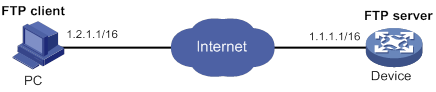
Configuration procedure
1. Configure IP addresses as shown in Figure 20. Make sure the device and PC can reach each other. (Details not shown.)
2. Configure the device (FTP server):
# Create a local user with the username abc and password 123456.
<Sysname> system-view
[Sysname] local-user abc class manage
[Sysname-luser-manage-abc] password simple 123456
# Assign the user role network-admin to the user. Set the working directory to the root directory of the flash memory.
[Sysname-luser-manage-abc] authorization-attribute user-role network-admin work-directory flash:/
# Assign the service type FTP to the user.
[Sysname-luser-manage-abc] service-type ftp
[Sysname-luser-manage-abc] quit
# Enable the FTP server.
[Sysname] ftp server enable
[Sysname] quit
# Examine the storage space for space insufficiency and delete unused files for more free space.
<Sysname> dir
Directory of flash:
0 drw- - Jun 29 2016 18:30:38 logfile
1 drw- - Jun 21 2016 14:51:38 diagfile
2 drw- - Jun 21 2016 14:51:38 seclog
3 -rw- 2943 Jul 02 2016 08:03:08 startup.cfg
4 -rw- 63901 Jul 02 2016 08:03:08 startup.mdb
5 -rw- 716 Jun 21 2016 14:58:02 hostkey
6 -rw- 572 Jun 21 2016 14:58:02 serverkey
7 -rw- 6541264 Aug 04 2016 20:40:49 backup.bin
473664 KB total (467080 KB free)
<Sysname> delete /unreserved flash:/backup.bin
3. Perform FTP operations from the PC (FTP client):
# Log in to the FTP server at 1.1.1.1 using the username abc and password 123456.
c:\> ftp 1.1.1.1
Connected to 1.1.1.1.
220 FTP service ready.
User (1.1.1.1:(none)): abc
331 Password required for abc.
Password:
230 User logged in.
# Use the ASCII mode to download the configuration file startup.cfg from the device to the PC for backup.
ftp> ascii
200 TYPE is now ASCII
ftp> get startup.cfg back-startup.cfg
# Use the binary mode to upload the file temp.bin to the device.
ftp> binary
200 TYPE is now 8-bit binary
ftp> put temp.bin
# Exit FTP.
ftp> bye
FTP server configuration example (distributed devices in standalone mode)
Network requirements
· Configure the device as an FTP server.
· Create a local user account with the username abc and password 123456 on the FTP server.
· Use the user account to log in to the FTP server from the FTP client.
· Upload the file temp.bin from the FTP client to the FTP server.
· Download the configuration file startup.cfg from the FTP server to the FTP client for backup.
Configuration procedure
1. Configure IP addresses as shown in Figure 21. Make sure the device and PC can reach other. (Details not shown.)
2. Configure the device (FTP server):
# Create a local user with the username abc and password 123456.
<Sysname> system-view
[Sysname] local-user abc class manage
[Sysname-luser-manage-abc] password simple 123456
# Assign the user role network-admin to the user. Set the working directory to the root directory of the flash memory on the active MPU. (To set the working directory to the root directory of the flash memory on the standby MPU, replace flash:/ with slot1#flash:/.)
[Sysname-luser-manage-abc] authorization-attribute user-role network-admin work-directory flash:/
# Assign the service type FTP to the user.
[Sysname-luser-manage-abc] service-type ftp
[Sysname-luser-manage-abc] quit
# Enable the FTP server.
[Sysname] ftp server enable
[Sysname] quit
# Examine the storage space for space insufficiency and delete unused files for more free space.
<Sysname> dir
Directory of flash:
0 drw- - Jun 29 2016 18:30:38 logfile
1 drw- - Jun 21 2016 14:51:38 diagfile
2 drw- - Jun 21 2016 14:51:38 seclog
3 -rw- 2943 Jul 02 2016 08:03:08 startup.cfg
4 -rw- 63901 Jul 02 2016 08:03:08 startup.mdb
5 -rw- 716 Jun 21 2016 14:58:02 hostkey
6 -rw- 572 Jun 21 2016 14:58:02 serverkey
7 -rw- 6541264 Aug 04 2016 20:40:49 backup.bin
473664 KB total (467080 KB free)
<Sysname> delete /unreserved flash:/backup.bin
3. Perform FTP operations from the PC (FTP client):
# Log in to the FTP server at 1.1.1.1 using the username abc and password 123456.
c:\> ftp 1.1.1.1
Connected to 1.1.1.1.
220 FTP service ready.
User(1.1.1.1:(none)):abc
331 Password required for abc.
Password:
230 User logged in.
# Use the ASCII mode to download the configuration file startup.cfg from the device to the PC for backup.
ftp> ascii
200 TYPE is now ASCII
ftp> get startup.cfg back-startup.cfg
# Use the binary mode to upload the file temp.bin from the PC to the root directory of the flash memory on the active MPU.
ftp> binary
200 TYPE is now 8-bit binary
ftp> put temp.bin
# Exit FTP.
ftp> bye
FTP server configuration example (centralized devices in IRF mode)
Network requirements
· Configure the IRF fabric as an FTP server.
· Create a local user account with the username abc and password 123456 on the FTP server.
· Use the user account to log in to the FTP server from the FTP client.
· Upload the file temp.bin from the FTP client to the FTP server.
· Download the configuration file config.cfg from the FTP server to the FTP client for backup.
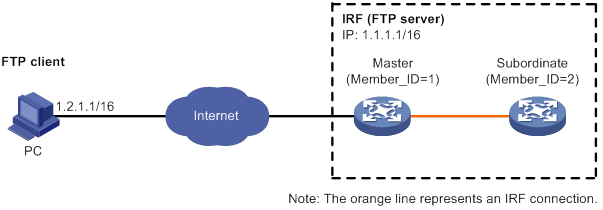
Configuration procedure
1. Configure IP addresses as shown in Figure 22. Make sure the IRF fabric and the PC can reach each other. (Details not shown.)
2. Configure the FTP server:
# Examine the storage space on the member devices. If the free space is insufficient, use the delete/unreserved file-url command to delete unused files. (Details not shown.)
# Create a local user with the username abc and password 123456.
<Sysname> system-view
[Sysname] local-user abc class manage
[Sysname-luser-manage-abc] password simple 123456
# Assign the user role network-admin to the user. Set the working directory to the root directory of the flash memory on the master. (To set the working directory to the root directory of the flash memory on the subordinate member, replace flash:/ with slot2#flash:/.)
[Sysname-luser-manage-abc] authorization-attribute user-role network-admin work-directory flash:/
# Assign the service type FTP to the user.
[Sysname-luser-manage-abc] service-type ftp
[Sysname-luser-manage-abc] quit
# Enable the FTP server.
[Sysname] ftp server enable
[Sysname] quit
3. Perform FTP operations from the FTP client:
# Log in to the FTP server at 1.1.1.1 using the username abc and password 123456.
c:\> ftp 1.1.1.1
Connected to 1.1.1.1.
220 FTP service ready.
User(1.1.1.1:(none)):abc
331 Password required for abc.
Password:
230 User logged in.
# Use the ASCII mode to download the configuration file config.cfg from the FTP server to the PC for backup.
ftp> ascii
200 TYPE is now ASCII
ftp> get config.cfg back-config.cfg
# Use the binary mode to upload the file temp.bin from the PC to the root directory of the flash memory on the master.
ftp> binary
200 TYPE is now 8-bit binary
ftp> put temp.bin
# Exit FTP.
ftp> bye
FTP server configuration example (distributed devices in IRF mode)
Network requirements
· Configure the IRF fabric as an FTP server.
· Create a local user account with the username abc and password 123456 on the FTP server.
· Use the user account to log in to the FTP server from the FTP client.
· Upload the file temp.bin from the FTP client to the FTP server.
· Download the configuration file config.cfg from the FTP server to the FTP client for backup.
Configuration procedure
1. Configure IP addresses as shown in Figure 23. Make sure the IRF fabric and the PC can reach each other. (Details not shown.)
2. Configure the FTP server:
# Examine the storage space on the member devices. If the free space is insufficient, use the delete/unreserved file-url command to delete unused files. (Details not shown.)
# Create a local user with the username abc and password 123456.
<Sysname> system-view
[Sysname] local-user abc class manage
[Sysname-luser-manage-abc] password simple 123456
# Assign the user role network-admin to the user. Set the working directory to the root directory of the flash memory on the global active MPU. (To set the working directory to the root directory of the flash memory on one of the global standby MPUs, replace flash:/ with, for example, chassis2#slot1#flash:/.)
[Sysname-luser-manage-abc] authorization-attribute user-role network-admin work-directory flash:/
# Assign the service type FTP to the user.
[Sysname-luser-manage-abc] service-type ftp
[Sysname-luser-manage-abc] quit
# Enable the FTP server.
[Sysname] ftp server enable
[Sysname] quit
3. Perform FTP operations from the FTP client:
# Log in to the FTP server at 1.1.1.1 using the username abc and password 123456.
c:\> ftp 1.1.1.1
Connected to 1.1.1.1.
220 FTP service ready.
User(1.1.1.1:(none)):abc
331 Password required for abc.
Password:
230 User logged in.
# Use the ASCII mode to download the configuration file config.cfg from the server to the client for backup.
ftp> ascii
200 TYPE is now ASCII
ftp> get config.cfg back-config.cfg
# Use the binary mode to upload the file temp.bin to the root directory of the flash memory on the global active MPU.
ftp> binary
200 TYPE is now 8-bit binary
ftp> put temp.bin
# Exit FTP.
ftp> bye
Using the device as an FTP client
Establishing an FTP connection
To access an FTP server, you must establish a connection from the FTP client to the FTP server.
To establish an IPv4 FTP connection:
|
Step |
Command |
Remarks |
|
1. Enter system view. |
system-view |
N/A |
|
2. (Optional.) Specify a source IP address for outgoing FTP packets. |
ftp client source { interface interface-type interface-number | ip source-ip-address } |
By default, no source IP address is specified. The device uses the primary IP address of the output interface as the source IP address. |
|
3. Return to user view. |
quit |
N/A |
|
4. Log in to the FTP server. |
·
(Method 1.) Log in to the FTP server
from user view: · (Method 2.) Log in to the FTP server from FTP client view: a. Enter FTP client view: b. Log in to the FTP server: |
The source IP address specified in the ftp command takes precedence over the one set by the ftp client source command. |
To establish an IPv6 FTP connection:
|
Step |
Command |
Remarks |
|
1. Enter system view. |
system-view |
N/A |
|
2. (Optional.) Specify the source IPv6 address for FTP packets sent by the FTP client. |
ftp client ipv6 source { interface interface-type interface-number | ipv6 source-ipv6-address } |
By default, no source IPv6 address is specified. The source address is automatically selected as defined in RFC 3484. |
|
3. Return to user view. |
quit |
N/A |
|
4. Log in to the FTP server. |
·
(Method 1.) Log in to the FTP server from user
view: · (Method 2.) Log in to the FTP server from FTP client view: a. Enter FTP client view: b. Log in to the FTP server: |
The source IP address specified in the ftp ipv6 command takes precedence over the one set by the ftp client ipv6 source command. |
Managing directories on the FTP server
Perform the following tasks in FTP client view:
|
Task |
Command |
|
Display directory and file information on the FTP server. |
·
Display the detailed information of a directory
or file on the FTP server: ·
Display the name of a directory or file on the
FTP server: |
|
Change the working directory on the FTP server. |
cd { directory | .. | / } |
|
Return to the upper level directory on the FTP server. |
cdup |
|
Display the working directory that is being accessed. |
pwd |
|
Create a directory on the FTP server. |
mkdir directory |
|
Delete a directory from the remote FTP server. |
rmdir directory |
Working with files on the FTP server
After you log in to the server, you can upload a file to or download a file from the authorized directory by following these steps:
1. Use the dir or ls command to display the directory and location of the file on the FTP server.
2. Delete unused files to get more free storage space.
3. Set the file transfer mode to ASCII for text files or to binary for non-text files.
4. Use the lcd command to change the local working directory of the FTP client. You can upload the file or save the downloaded file in this directory.
5. Upload or download the file.
To work with files on an FTP server, execute the following commands in FTP client view:
|
Task |
Command |
Remarks |
|
Display directory or file information on the FTP server. |
·
Display the detailed information of a directory
or file on the FTP server: ·
Display the name of a directory or file on the
FTP server: |
N/A |
|
Delete a file from the FTP server permanently. |
delete remotefile |
N/A |
|
Set the file transfer mode. |
·
Set the file transfer mode to ASCII: ·
Set the file transfer mode to binary: |
The default file transfer mode is binary. |
|
Change the FTP operation mode. |
passive |
The default mode is passive. |
|
Display or change the local working directory of the FTP client. |
lcd [ directory | / ] |
N/A |
|
Upload a file to the FTP server. |
put localfile [ remotefile ] |
N/A |
|
Download a file from the FTP server. |
get remotefile [ localfile ] |
N/A |
|
Add the content of a file on the FTP client to a file on the FTP server. |
append localfile [ remotefile ] |
N/A |
|
Specify the retransmit marker. |
restart marker |
Use this command together with the put, get, or append command. |
|
Update the local file. |
newer remotefile |
N/A |
|
Get the missing part of a file. |
reget remotefile [ localfile ] |
N/A |
|
Rename the file. |
rename [ oldfilename [ newfilename ] ] |
N/A |
Changing to another user account
After you log in to the FTP server, you can initiate an FTP authentication to change to a new account. By changing to a new account, you can get a different privilege without re-establishing the FTP connection.
For successful account change, you must enter the new username and password correctly. A wrong username or password can cause the FTP connection to be disconnected.
To change to another user account, execute the following command in user view:
|
Task |
Command |
|
Initiate an FTP authentication on the current FTP connection. |
user username [ password ] |
Maintaining and troubleshooting the FTP connection
Perform the following tasks in FTP client view:
|
Task |
Command |
Remarks |
|
Display FTP commands on the FTP server. |
rhelp |
N/A |
|
Display FTP commands help information on the FTP server. |
rhelp protocol-command |
N/A |
|
Display FTP server status. |
rstatus |
N/A |
|
Display detailed information about a directory or file on the FTP server. |
rstatus remotefile |
N/A |
|
Display FTP connection status. |
status |
N/A |
|
Display the system information of the FTP server. |
system |
N/A |
|
Enable or disable FTP operation information display. |
verbose |
By default, this function is enabled. |
|
Enable or disable FTP client debugging. |
debug |
By default, FTP client debugging is disabled. |
|
Clear the reply information in the buffer. |
reset |
N/A |
Terminating the FTP connection
Execute one of the following commands in FTP client view:
|
Task |
Command |
|
Terminate the connection to the FTP server without exiting FTP client view. |
· disconnect · close |
|
Terminate the connection to the FTP server and return to user view. |
· bye · quit |
Displaying command help information
Execute one of the following commands in FTP client view:
|
Task |
Command |
|
Display command help information. |
· help [ command-name ] · ? [ command-name ] |
Displaying and maintaining the FTP client
Execute the display command in any view.
|
Task |
Command |
|
Display source IP address information on the FTP client. |
display ftp client source |
FTP client configuration example (centralized devices in standalone mode)
Network requirements
As shown in Figure 24, the PC is acting as an FTP server. A user account with the username abc and password 123456 has been created on the PC.
· Use the device as an FTP client to log in to the FTP server.
· Download the file temp.bin from the PC to the device.
· Upload the configuration file startup.cfg from the device to the PC for backup.
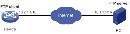
Configuration procedure
# Configure IP addresses as shown in Figure 24. Make sure the device and PC can reach each other. (Details not shown.)
# Examine the storage space of the device. If the free space is insufficient, use the delete/unreserved file-url command to delete unused files. (Details not shown.)
# Log in to the FTP server at 10.1.1.1 using the username abc and password 123456.
<Sysname> ftp 10.1.1.1
Press CTRL+C to abort.
Connected to 10.1.1.1 (10.1.1.1).
220 WFTPD 2.0 service (by Texas Imperial Software) ready for new user
User (10.1.1.1:(none)): abc
331 Give me your password, please
Password:
230 Logged in successfully
Remote system type is MSDOS.
ftp>
# Set the file transfer mode to binary.
ftp> binary
200 TYPE is now 8-bit binary
# Download the file temp.bin from the PC to the device.
ftp> get temp.bin
local: temp.bin remote: temp.bin
150 Connecting to port 47457
226 File successfully transferred
23951480 bytes received in 95.399 seconds (251.0 kbyte/s)
# Use the ASCII mode to upload the configuration file startup.cfg from the device to the PC for backup.
ftp> ascii
200 TYPE is now ASCII
ftp> put startup.cfg back-startup.cfg
local: startup.cfg remote: back-startup.cfg
150 Connecting to port 47461
226 File successfully transferred
3494 bytes sent in 5.646 seconds (618.00 kbyte/s)
ftp> bye
221-Goodbye. You uploaded 2 and downloaded 2 kbytes.
221 Logout.
<Sysname>
FTP client configuration example (distributed devices in standalone mode)
Network requirements
As shown in Figure 25, the PC is acting as an FTP server. A user account with the username abc and password 123456 has been created on the PC.
· Use the device as an FTP client to log in to the FTP server.
· Download the file temp.bin from the PC to the device.
· Upload the configuration file startup.cfg from the device to the PC for backup.
Configuration procedure
# Configure IP addresses as shown in Figure 25. Make sure the device and PC can reach each other. (Details not shown.)
# Examine the storage space of the device. If the free space is insufficient, use the delete/unreserved file-url command to delete unused files. (Details not shown.)
# Log in to the FTP server at 10.1.1.1 using the username abc and password 123456.
<Sysname> ftp 10.1.1.1
Press CTRL+C to abort.
Connected to 10.1.1.1 (10.1.1.1).
220 WFTPD 2.0 service (by Texas Imperial Software) ready for new user
User (10.1.1.1:(none)): abc
331 Give me your password, please
Password:
230 Logged in successfully
Remote system type is MSDOS.
ftp>
# Set the file transfer mode to binary.
ftp> binary
200 TYPE is now 8-bit binary
# Download the file temp.bin from the PC to the root directory of the flash memory on the active MPU.
ftp> get temp.bin
local: temp.bin remote: temp.bin
150 Connecting to port 47457
226 File successfully transferred
23951480 bytes received in 95.399 seconds (251.0 kbyte/s)
# Download the file temp.bin from the PC to the root directory of the flash memory on the standby MPU (in slot 1).
ftp> get temp.bin slot1#flash:/temp.bin
# Use the ASCII mode to upload the configuration file startup.cfg from the device to the PC for backup.
ftp> ascii
200 TYPE is now ASCII
ftp> put startup.cfg back-startup.cfg
local: startup.cfg remote: back-startup.cfg
150 Connecting to port 47461
226 File successfully transferred
3494 bytes sent in 5.646 seconds (618.00 kbyte/s)
ftp> bye
221-Goodbye. You uploaded 2 and downloaded 2 kbytes.
221 Logout.
<Sysname>
FTP client configuration example (centralized devices in IRF mode)
Network requirements
As shown in Figure 26, the PC is acting as an FTP server. A user account with the username abc and password 123456 has been created on the PC.
· Use the IRF fabric as an FTP client to log in to the FTP server.
· Download the file temp.bin from the FTP server to the FTP client.
· Upload the configuration file config.cfg from the FTP client to the FTP server for backup.
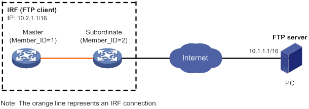
Configuration procedure
# Configure IP addresses as shown in Figure 26. Make sure the IRF fabric and PC can reach each other. (Details not shown.)
# Examine the storage space on the member devices. If the free space is insufficient, use the delete/unreserved file-url command to delete unused files. (Details not shown.)
# Log in to the FTP server at 10.1.1.1 using the username abc and password 123456.
<Sysname> ftp 10.1.1.1
Press CTRL+C to abort.
Connected to 10.1.1.1 (10.1.1.1).
220 WFTPD 2.0 service (by Texas Imperial Software) ready for new user
User (10.1.1.1:(none)): abc
331 Give me your password, please
Password:
230 Logged in successfully
Remote system type is MSDOS.
ftp>
# Set the file transfer mode to binary.
ftp> binary
200 TYPE is now 8-bit binary
# Download the file temp.bin from the PC to the root directory of the flash memory on the master device.
ftp> get temp.bin
local: temp.bin remote: temp.bin
150 Connecting to port 47457
226 File successfully transferred
23951480 bytes received in 95.399 seconds (251.0 kbyte/s)
# Download the file temp.bin from the PC to the root directory of the flash memory on the subordinate member (with member ID of 2).
ftp> get temp.bin slot2#flash:/temp.bin
# Use the ASCII mode to upload the configuration file config.cfg from the IRF fabric to the PC for backup.
ftp> ascii
200 TYPE is now ASCII
ftp> put config.cfg back-config.cfg
local: config.cfg remote: back-config.cfg
150 Connecting to port 47461
226 File successfully transferred
3494 bytes sent in 5.646 seconds (618.00 kbyte/s)
ftp> bye
221-Goodbye. You uploaded 2 and downloaded 2 kbytes.
221 Logout.
<Sysname>
FTP client configuration example (distributed devices in IRF mode)
Network requirements
As shown in Figure 27, the PC is acting as an FTP server. A user account with the username abc and password 123456 has been created on the PC.
· Use the IRF fabric as an FTP client to log in to the FTP server.
· Download the file temp.bin from the FTP server to the FTP client.
· Upload the configuration file config.cfg from the FTP client to the FTP server for backup.
Configuration procedure
# Configure IP addresses as shown in Figure 27. Make sure the IRF fabric and PC can reach each other. (Details not shown.)
# Examine the storage space on the member devices. If the free space is insufficient, use the delete/unreserved file-url command to delete unused files. (Details not shown.)
# Log in to the FTP server using the username abc and password 123456.
<Sysname> ftp 10.1.1.1
Press CTRL+C to abort.
Connected to 10.1.1.1 (10.1.1.1).
220 WFTPD 2.0 service (by Texas Imperial Software) ready for new user
User (10.1.1.1:(none)): abc
331 Give me your password, please
Password:
230 Logged in successfully
Remote system type is MSDOS.
ftp>
# Set the file transfer mode to binary.
ftp> binary
200 TYPE is now 8-bit binary
# Download the file temp.bin from the PC to the root directory of the flash memory on the global active MPU.
ftp> get temp.bin
local: temp.bin remote: temp.bin
150 Connecting to port 47457
226 File successfully transferred
23951480 bytes received in 95.399 seconds (251.0 kbyte/s)
# Download the file temp.bin from the PC to the root directory of the flash memory on the global standby MPUs.
ftp> get temp.bin chassis1#slot1#flash:/temp.bin
ftp> get temp.bin chassis2#slot0#flash:/temp.bin
ftp> get temp.bin chassis2#slot1#flash:/temp.bin
# Use the ASCII mode to upload the configuration file config.cfg from the IRF fabric to the PC for backup.
ftp> ascii
200 TYPE is now ASCII
ftp> put config.cfg back-config.cfg
local: config.cfg remote: back-config.cfg
150 Connecting to port 47461
226 File successfully transferred
3494 bytes sent in 5.646 seconds (618.00 kbyte/s)
ftp> bye
221-Goodbye. You uploaded 2 and downloaded 2 kbytes.
221 Logout.
<Sysname>
Configuring TFTP
Trivial File Transfer Protocol (TFTP) is a simplified version of FTP for file transfer over secure reliable networks. TFTP uses UDP port 69 for data transmission. In contrast to TCP-based FTP, TFTP does not require authentication or complex message exchanges, and is easier to deploy. TFTP is suited for reliable network environments.
As shown in Figure 28, the device can only act as a TFTP client. You can upload a file from the device to the TFTP server or download a file from the TFTP server to the device. If you download a file with a file name that exists in the target directory, the device deletes the existing file and saves the new one. If file download fails due to network disconnection or other reasons, the original file cannot be restored. Therefore, use a nonexistent file name instead.
Figure 28 TFTP application scenario
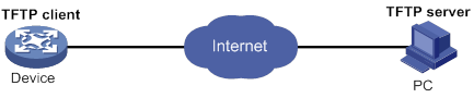
Command and hardware compatibility
IPv6-related parameters are not supported on the following routers:
· MSR810/810-W/810-W-DB/810-LM/810-W-LM/810-10-PoE/810-LM-HK/810-W-LM-HK/810-LMS/810-LUS.
· MSR3600-28-SI/3600-51-SI.
FIPS compliance
The device supports the FIPS mode that complies with NIST FIPS 140-2 requirements. Support for features, commands, and parameters might differ in FIPS mode and non-FIPS mode. For more information about FIPS mode, see Security Configuration Guide.
TFTP is not supported in FIPS mode.
Configuring the device as an IPv4 TFTP client
|
Step |
Command |
Remarks |
|
1. Enter system view. |
system-view |
N/A |
|
2. (Optional.) Use an ACL to control the client's access to TFTP servers. |
tftp-server acl acl-number |
By default, no ACL is used for access control. |
|
3. Specify the source IP address for TFTP packets sent by the TFTP client. |
tftp client source { interface interface-type interface-number | ip source-ip-address } |
By default, no source IP address is specified. The device uses the primary IP address of the output interface as the source IP address. |
|
4. Return to user view. |
quit |
N/A |
|
5. Download or upload a file in an IPv4 network. |
tftp tftp-server { get | put | sget } source-filename [ destination-filename ] [ vpn-instance vpn-instance-name ] [ dscp dscp-value | source { interface interface-type interface-number | ip source-ip-address } ] * |
The source IP address specified in this command takes precedence over the one set by the tftp client source command. Use this command in user view. |
Configuring the device as an IPv6 TFTP client
|
Step |
Command |
Remarks |
|
1. Enter system view. |
system-view |
N/A |
|
2. (Optional.) Use an ACL to control the client's access to TFTP servers. |
tftp-server ipv6 acl ipv6-acl-number |
By default, no ACL is used for access control. |
|
3. Specify the source IPv6 address for TFTP packets sent by the TFTP client. |
tftp client ipv6 source { interface interface-type interface-number | ipv6 source-ipv6-address } |
By default, no source IPv6 address is specified. The source address is automatically selected as defined in RFC 3484. |
|
4. Return to user view. |
quit |
N/A |
|
5. Download or upload a file in an IPv6 network. |
tftp ipv6 tftp-server [ -i interface-type interface-number ] { get | put | sget } source-filename [ destination-filename ] [ vpn-instance vpn-instance-name ] [ dscp dscp-value | source { interface interface-type interface-number | ipv6 source-ipv6-address } ] * |
The source IP address specified in this command takes precedence over the one set by the tftp client ipv6 source command. Use this command in user view. |
Managing file systems
Overview
File systems
The following matrix shows the supported storage medium types:
|
Hardware |
Supported storage medium types |
|
MSR810/810-W/810-W-DB/810-LM/810-W-LM/810-10-PoE/810-LM-HK/810-W-LM-HK/810-LMS/810-LUS |
· Flash memory · USB disk · SD card |
|
MSR2600-6-X1/2600-10-X1 |
· Flash memory · USB disk |
|
MSR 2630 |
· Flash memory · USB disk |
|
MSR3600-28/3600-51 |
· Flash memory · USB disk |
|
MSR3600-28-SI/3600-51-SI |
· Flash memory · USB disk |
|
MSR3610-X1/3610-X1-DP/3610-X1-DC/3610-X1-DP-DC |
· Flash memory · USB disk · SD card |
|
MSR 3610/3620/3620-DP/3640/3660 |
MSR 3610/3620/3640/3660: · CF card · USB disk MSR3620-DP: · SD card · USB disk |
|
MSR5620/5660/5680 |
MSR 5660/5680: · CF card · USB disk MSR5620: · SD card · USB disk |
File system location
(Centralized devices in IRF mode.) To identify a file system on the master device, you do not need to specify the file system location. To identify a file system on a subordinate member device, you must specify the file system location in the slotn# format. The n argument represents the IRF member ID of the member device. For example, the location is slot2# for a file system that resides on member device 2.
(Distributed devices in standalone mode.) To identify a file system on the active MPU, you do not need to specify the file system location. To identify a file system on the standby MPU, you must specify the file system location in the slotn# format. The n argument represents the slot number of a card. For example, the location is slot16# for a file system that resides on the card in slot 16.
(Distributed devices in IRF mode.) To identify a file system on the global active MPU, you do not need to specify the file system location. To identify a file system on a global standby MPU, you must specify the file system location in the chassism#slotn# format. The m argument represents the IRF member ID of the member device. The n argument represents the slot number of a card. For example, the location is chassis2#slot16# for a file system that resides on the MPU in slot 16 of member device 2.
File system naming conventions
The name of the file system on a flash memory has the following parts:
· File system location. For more information, see "File system location".
· Storage medium type flash.
· Colon (:).
The name of a file system on a CF card, TF card, or USB disk has the following parts:
· File system location. For more information, see "File system location".
· Storage medium type, cf, sd, or usb.
· Sequence number, a lower-case English letter such as a, b, or c.
· Colon (:).
For example, the file system on the first USB disk is named usba:.
|
|
IMPORTANT: File system names are case sensitive and must be entered in lower case. |
Default file system
You are working with the default file system by default after you log in. To specify a file or directory on the default file system, you do not need to specify the file system name. For example, you do not need to specify any location information if you want to save the running configuration to the root directory of the default file system.
To change the default file system, use the BootWare menu. For more information, see the software release notes.
Directories
Directories in a file system are structured in a tree form.
Root directory
The root directory is represented by a forwarding slash (/). For example, flash:/ represents the root directory of the flash memory.
Working directory
The working directory is also called the current directory.
The default working directory is the root directory of the file system on the flash memory or CF card. (Centralized devices in standalone mode.)
The default working directory is the root directory of the file system on the master's flash memory or CF card. (Centralized devices in IRF mode.)
The default working directory is the root directory of the file system on the active MPU's CF card. (Distributed devices in standalone mode.)
The default working directory is the root directory of the file system on the global active MPU's CF card. (Distributed devices in IRF mode.)
Directory naming conventions
When you specify a name for a directory, follow these conventions:
· A directory name can contain letters, digits, and special characters except for asterisks (*), vertical bars (|), forward slashes (/), backward slashes (\), question marks (?), left angle brackets (<), right angle brackets (>), quotation marks ("), and colons (:).
· A directory whose name starts with a dot character (.) is a hidden directory. To prevent the system from hiding a directory, make sure the directory name does not start with a dot character.
Commonly used directories
The device has some factory-default directories. The system automatically creates directories during operation. These directories include:
· diagfile—Stores diagnostic information files.
· license—Stores license files.
· logfile—Stores log files.
· seclog—Stores security log files.
· versionInfo—Stores software version information files.
Files
File naming conventions
When you specify a name for a file, follow these conventions:
· A file name can contain letters, digits, and special characters except for asterisks (*), vertical bars (|), forward slashes (/), backward slashes (\), question marks (?), left angle brackets (<), right angle brackets (>), quotation marks ("), and colons (:).
· A file whose name starts with a dot character (.) is a hidden file. To prevent the system from hiding a file, make sure the file name does not start with a dot character.
Common file types
The device is shipped with some files. The system automatically creates files during operation. The types of these files include:
· .ipe file—Compressed software image package file.
· .bin file—Software image file.
· .cfg file—Configuration file.
· .mdb file—Binary configuration file.
· .log file—Log file.
Hidden files and directories
Some system files and directories are hidden. For correct system operation and full functionality, do not modify or delete hidden files or directories.
Specifying a directory name or file name
Specifying a directory name
To specify a directory, you can use the absolute path or a relative path. For example, the working directory is flash:/. To specify the test2 directory in Figure 29, you can use the following methods:
· flash:/test/test1/test2 (absolute path)
· flash:/test/test1/test2/ (absolute path)
· test/test1/test2 (relative path)
· test/test1/test2/ (relative path)
Figure 29 Sample directory hierarchy
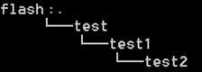
Specifying a file name
To specify a file, use the following methods:
· Enter the absolute path of the file and the file name in the format of filesystem/directory1/directory2/…/directoryn/filename, where directoryn is the directory in which the file resides.
· Enter the relative path of the file and the file name.
For example, the working directory is flash:/. The samplefile.cfg file is in the test2 directory shown in Figure 29. To specify the file, you can use the following methods:
· flash:/test/test1/test2/samplefile.cfg
· test/test1/test2/samplefile.cfg
Command and hardware compatibility
Commands and descriptions for centralized devices apply to the following routers:
· MSR810/810-W/810-W-DB/810-LM/810-W-LM/810-10-PoE/810-LM-HK/810-W-LM-HK/810-LMS/810-LUS.
· MSR2600-6-X1/2600-10-X1.
· MSR 2630.
· MSR3600-28/3600-51.
· MSR3600-28-SI/3600-51-SI.
· MSR3610-X1/3610-X1-DP/3610-X1-DC/3610-X1-DP-DC.
· MSR 3610/3620/3620-DP/3640/3660.
· MSR810-LM-GL/810-W-LM-GL/830-6EI-GL/830-10EI-GL/830-6HI-GL/830-10HI-GL/2600-6-X1-GL/3600-28-SI-GL.
Commands and descriptions for distributed devices apply to the following routers:
· MSR5620.
· MSR 5660.
· MSR 5680.
FIPS compliance
The device supports the FIPS mode that complies with NIST FIPS 140-2 requirements. Support for features, commands, and parameters might differ in FIPS mode and non-FIPS mode. For more information about FIPS mode, see Security Configuration Guide.
File system management restrictions and guidelines
To avoid file system corruption, do not perform the following tasks during file system management:
· Installing or removing storage media.
· Installing or removing cards. (Distributed devices in standalone or IRF mode.)
· Performing an active/standby switchover. (Distributed devices in standalone mode.)
· Performing a switchover between the global active MPU and a global standby MPU. (Distributed devices in IRF mode.)
· Performing master/subordinate switchover. (Centralized devices in IRF mode.)
If you remove a storage medium while a directory or file on the medium is being accessed, the device might not recognize the medium when you reinstall it. To reinstall this kind of storage medium, perform one of the following tasks:
· If you were accessing a directory on the storage medium, change the working directory.
· If you were accessing a file on the storage medium, close the file.
· If another administrator was accessing the storage medium, unmount the file system on the storage medium.
Make sure a USB disk is not write protected before an operation that requires the write right on the disk.
You cannot access a file system that is being formatted or repaired. To access a file system after it is formatted or repaired, use one of the following methods:
· Use the absolute path to specify a file or directory. For example, use the dir flash:/ command to display the files and directories in the file system on the flash memory.
· Use the cd command to change the working directory to the root directory of the file system before accessing a file or directory in the file system. For example, to display the files and directories in the root directory of the file system on the flash memory, perform the following tasks:
a. Use the cd flash:/ command to change the working directory to the root directory of the file system.
b. Execute the dir command.
Before managing file systems, directories, and files, make sure you know the possible impact.
Managing storage media and file systems
Mounting or unmounting a file system
Generally, file systems on a hot-swappable storage medium are automatically mounted when the storage medium is connected to the device. If the system cannot recognize a file system, you must mount the file system before you can access it.
To remove a hot-swappable storage medium from the device, you must first unmount all file systems on the storage medium to disconnect the medium from the device. Removing a connected hot-swappable storage medium might damage files on the storage medium or even the storage medium itself.
To use an unmounted file system, you must mount the file system again.
Feature and hardware compatibility
|
Hardware |
Storage medium mounting/unmounting compatibility |
|
|
MSR810/810-W/810-W-DB/810-LM/810-W-LM/810-10-PoE/810-LM-HK/810-W-LM-HK/810-LMS/810-LUS |
Yes |
|
|
MSR2600-6-X1/2600-10-X1 |
Yes |
|
|
MSR 2630 |
Yes |
|
|
MSR3600-28/3600-51 |
Yes |
|
|
MSR3600-28-SI/3600-51-SI |
Yes |
|
|
MSR3610-X1/3610-X1-DP/3610-X1-DC/3610-X1-DP-DC |
Yes |
|
|
MSR 3610/3620/3620-DP/3640/3660 |
Yes |
|
|
MSR5620/5660/5680 |
Yes |
|
|
Hardware |
Storage medium mounting/unmounting compatibility |
|
|
MSR810-LM-GL |
Yes |
|
|
MSR810-W-LM-GL |
Yes |
|
|
MSR830-6EI-GL |
No |
|
|
MSR830-10EI-GL |
Yes |
|
|
MSR830-6HI-GL |
Yes |
|
|
MSR830-10HI-GL |
Yes |
|
|
MSR2600-6-X1-GL |
Yes |
|
|
MSR3600-28-SI-GL |
Yes |
|
Restrictions and guidelines
You can mount or unmount a file system only when no other users are accessing the file system.
To prevent a USB disk and the USB interface from being damaged, make sure the following requirements are met before unmounting file systems on the USB disk:
· The system has recognized the USB disk.
· The USB disk LED is not blinking.
Configuration procedure
Perform one of the following tasks in user view as appropriate:
|
Task |
Command |
|
Mount a file system. |
mount filesystem |
|
Unmount a file system. |
umount filesystem |
Formatting a file system
|
|
CAUTION: Formatting a file system permanently deletes all files and directories in the file system. You cannot restore the deleted files or directories. |
You can format a file system only when no other users are accessing the file system.
Perform this task in user view.
|
Task |
Command |
|
Format a file system. |
format filesystem |
Repairing a file system
If part of a file system is inaccessible, use this task to examine and repair the file system.
You can repair a file system only when no other users are accessing the file system.
Perform this task in user view.
|
Task |
Command |
|
Repair a file system. |
fixdisk filesystem |
Managing directories
Displaying directory information
Perform this task in user view.
|
Task |
Command |
|
Display directory or file information. |
dir [ /all ] [ file | directory | /all-filesystems ] |
Displaying the working directory
Perform this task in user view.
|
Task |
Command |
|
Display the working directory. |
pwd |
Changing the working directory
Perform this task in user view.
|
Task |
Command |
|
Change the working directory. |
cd { directory | .. } |
Creating a directory
Perform this task in user view.
|
Task |
Command |
|
Create a directory. |
mkdir directory |
Renaming a directory
Perform this task in user view.
|
Task |
Command |
|
Rename a directory. |
rename source-directory dest-directory |
Archiving or extracting directories
When you archive or extract directories or display archived directories, files in the directories are also archived, extracted, or displayed.
Perform the following tasks in user view:
|
Task |
Command |
Remarks |
|
Archive directories. |
tar create [ gz ] archive-file dest-file [ verbose ] source source-directory &<1-5> |
N/A |
|
Extract directories. |
tar extract archive-file file [ verbose ] [ screen | to directory ] |
Specify a small archive file if you specify the screen keyword. If you specify a large archive file, the command might take a long time and cause the configuration terminal to crash. You cannot abort the operation. |
|
Display archived directories. |
tar list archive-file file |
N/A |
Deleting a directory
To delete a directory, you must delete all files and subdirectories in the directory. To delete a file, use the delete command. To delete a subdirectory, use the rmdir command.
Deleting a directory permanently deletes all its files in the recycle bin, if any.
Perform this task in user view.
|
Task |
Command |
|
Delete a directory. |
rmdir directory |
Setting the operation mode for directories
The device supports the following directory operation modes:
· alert—The system prompts for confirmation when your operation might cause problems such as data loss. This mode provides an opportunity to cancel a disruptive operation.
· quiet—The system does not prompt for confirmation.
To set the operation mode for directories:
|
Step |
Command |
Remarks |
|
1. Enter system view. |
system-view |
N/A |
|
2. Set the operation mode for directories. |
file prompt { alert | quiet } |
The default mode is alert. This command also sets the operation mode for files. |
Managing files
You can create a file by copying a file, downloading a file, or using the save command. For more information about downloading a file, see "Configuring FTP" and "Configuring TFTP." For more information about the save command, see Fundamentals Command Reference.
Displaying file information
Perform this task in user view.
|
Task |
Command |
|
Display directory or file information. |
dir [ /all ] [ file | directory | /all-filesystems ] |
Displaying the contents of a text file
Perform this task in user view.
|
Task |
Command |
|
Display the contents of a text file. |
more file |
Renaming a file
Perform this task in user view.
|
Task |
Command |
|
Rename a file. |
rename source-file dest-file |
Copying a file
Perform this task in user view.
|
Task |
Command |
|
Copy a file. |
·
In non-FIPS mode: ·
In FIPS mode: |
Moving a file
Perform this task in user view.
|
Task |
Command |
|
Move a file. |
move source-file { dest-file | dest-directory } |
Compressing or decompressing a file
Perform the following tasks in user view:
|
Task |
Command |
|
Compress a file. |
gzip file |
|
Decompress a file. |
gunzip file |
Archiving or extracting files
Perform the following tasks in user view:
|
Task |
Command |
|
Archive files. |
tar create [ gz ] archive-file dest-file [ verbose ] source source-file &<1-5> |
|
Extract files. |
tar extract archive-file file [ verbose ] [ screen | to directory ] |
|
Display the names of archived files. |
tar list archive-file file |
Deleting or restoring a file
You can delete a file permanently or move it to the recycle bin. A file moved to the recycle bin can be restored, but a permanently deleted file cannot.
Files in the recycle bin occupy storage space. To save storage space, periodically empty the recycle bin by using the reset recycle-bin command.
Perform the following tasks in user view:
|
Task |
Command |
|
Delete a file by moving it to the recycle bin. |
delete file |
|
Restore a file from the recycle bin. |
undelete file |
|
Delete a file permanently. |
delete /unreserved file |
|
|
IMPORTANT: Do not use the delete command to delete files from the recycle bin. To delete files from the recycle bin, use the reset recycle-bin command. |
Deleting files from the recycle bin
Each file system has a recycle bin of its own. A recycle bin is a folder named .trash in the root directory of a file system.
To view which files or directories are in a recycle bin, use either of the following methods:
· Access the file system and execute the dir/all .trash command.
· Execute the cd .trash command to enter the recycle bin folder, and then execute the dir command.
To delete files from a recycle bin, perform the following task in user view:
|
Task |
Command |
|
Delete files from the recycle bin. |
reset recycle-bin [ /force ] |
Calculating the file digest
File digests are used to verify file integrity.
Use the following commands in user view:
|
Task |
Command |
|
Calculate the digest of a file by using the SHA-256 algorithm. |
sha256sum file |
|
Calculate the digest of a file by using the MD5 algorithm. |
md5sum file |
Setting the operation mode for files
The device supports the following file operation modes:
· alert—The system prompts for confirmation when your operation might cause problems such as file corruption or data loss. This mode provides an opportunity to cancel a disruptive operation.
· quiet—The system does not prompt for confirmation.
To set the operation mode for files:
|
Step |
Command |
Remarks |
|
1. Enter system view. |
system-view |
N/A |
|
2. Set the operation mode for files. |
file prompt { alert | quiet } |
The default mode is alert. This command also sets the operation mode for directories. |
Using the automatic copying feature
The following matrix shows the feature and hardware compatibility:
|
Hardware |
Automatic copying compatibility |
|
MSR810/810-W/810-W-DB/810-LM/810-W-LM/810-10-PoE/810-LM-HK/810-W-LM-HK |
Yes |
|
MSR810-LMS/810-LUS |
No |
|
MSR2600-6-X1/2600-10-X1 |
No |
|
MSR 2630 |
No |
|
MSR3600-28/3600-51 |
No |
|
MSR3600-28-SI/3600-51-SI |
No |
|
MSR3610-X1/3610-X1-DP/3610-X1-DC/3610-X1-DP-DC |
No |
|
MSR 3610/3620/3620-DP/3640/3660 |
No |
|
MSR5620/5660/5680 |
No |
|
Hardware |
Automatic copying compatibility |
|
|
MSR810-LM-GL |
Yes |
|
|
MSR810-W-LM-GL |
Yes |
|
|
MSR830-6EI-GL |
Yes |
|
|
MSR830-10EI-GL |
Yes |
|
|
MSR830-6HI-GL |
Yes |
|
|
MSR830-10HI-GL |
Yes |
|
|
MSR2600-6-X1-GL |
No |
|
|
MSR3600-28-SI-GL |
No |
|
The automatic copying feature automatically copies files from a hot-swappable storage medium to the device when you connect the storage medium to the device. You can use this feature to update files on a device without logging in to the device. For example, you can use this feature to update the webpages and video files on a vehicle-mounted AP.
During the automatic copying process, observe the LEDs on the device to determine progress and results.
· If the SYS LED flashes quickly, the copy operation is in progress.
· If the SYS LED flashes normally, the copy operation is completed.
· If the ALARM LED flashes for 10 seconds, the copy operation failed.
Possible reasons for copy operation failures include:
· You are not assigned the write right to the destination directory.
· The destination directory does not have sufficient free storage space to save the files.
· The hot-swappable storage medium is removed before the copy operation is completed.
· The specified source directory does not exist on the hot-swappable storage medium.
For the automatic copying feature to operate correctly, you must specify the source directory and the destination directory for the copy operation.
To specify the source directory and the destination directory for the automatic copying feature:
|
Step |
Command |
Remarks |
|
1. Enter system view. |
system-view |
N/A |
|
2. Specify the source directory. |
auto-copy source-directory source-directory |
By default, no source directory is specified for the automatic copying feature. |
|
3. Specify the destination directory. |
auto-copy destination-directory destination-directory |
By default, no destination directory is specified for the automatic copying feature. |
Synchronizing files and directories from an Rsync server
The following matrix shows the feature and hardware compatibility:
|
Hardware |
File and directory synchronization compatibility |
|
MSR810/810-W/810-W-DB/810-LM/810-W-LM/810-10-PoE/810-LM-HK/810-W-LM-HK |
Yes |
|
MSR810-LMS/810-LUS |
No |
|
MSR2600-6-X1/2600-10-X1 |
No |
|
MSR 2630 |
No |
|
MSR3600-28/3600-51 |
No |
|
MSR3600-28-SI/3600-51-SI |
No |
|
MSR3610-X1/3610-X1-DP/3610-X1-DC/3610-X1-DP-DC |
No |
|
MSR 3610/3620/3620-DP/3640/3660 |
No |
|
MSR5620/5660/5680 |
No |
|
Hardware |
File and directory synchronization compatibility |
|
|
MSR810-LM-GL |
Yes |
|
|
MSR810-W-LM-GL |
Yes |
|
|
MSR830-6EI-GL |
Yes |
|
|
MSR830-10EI-GL |
Yes |
|
|
MSR830-6HI-GL |
Yes |
|
|
MSR830-10HI-GL |
Yes |
|
|
MSR2600-6-X1-GL |
No |
|
|
MSR3600-28-SI-GL |
No |
|
This feature synchronizes files and directories from an IPv4 Rsync server to a directory on the device.
To synchronize files and directories from an IPv4 Rsync server:
|
Step |
Command |
Remarks |
|
1. Enter system view. |
system-view |
N/A |
|
2. Specify the source IP address for packets sent to the Rsync server. |
rsync client source { interface interface-type interface-number | ip source-ip } |
By default, no outbound interface or source IP address is specified. The device uses the primary IPv4 address of the outbound interface as the source IP address for outgoing packets during file and directory synchronization. |
|
3. Synchronize files and directories from the Rsync server. |
rsync [ -s source-ip ] rsync-server { source-file | source-directory } dest-directory [ user-name password ] |
N/A |
Managing configuration files
Overview
You can manage configuration files from the CLI or the Boot ROM menu. The following information explains how to manage configuration files from the CLI.
A configuration file saves a set of commands for configuring software features on the device. You can save any configuration to a configuration file so the configuration can survive a reboot. You can also back up configuration files to a host for future use.
Configuration types
The device has the following types of configurations: factory defaults, startup configuration, and running configuration.
Factory defaults
The device is shipped with some basic settings called factory defaults. These default settings ensure that the device can start up and run correctly when it does not have a startup configuration file or when the configuration file is corrupt.
To display factory defaults, use the display default-configuration command.
Startup configuration
The device uses startup configuration to configure software features during startup. After the device starts up, you can specify the configuration file to be loaded at the next startup. This configuration file is called the next-startup configuration file. The configuration file that has been loaded is called the current startup configuration file.
If no next-startup configuration files exist, the device starts up with the factory defaults.
You can display the startup configuration by using one of the following methods:
· To display the contents of the current startup configuration file, execute the display current-configuration command before changing the configuration after the device reboots.
· To display the contents of the next-startup configuration file, use the display saved-configuration command.
· Use the display startup command to display names of the current startup configuration file and next-startup configuration files. Then, you can use the more command to display the contents of the specified startup configuration file.
Running configuration
The running configuration includes unchanged startup settings and new settings. The running configuration is stored in memory and is cleared at a device reboot or power off. To use the running configuration after a power cycling or reboot, save it to a configuration file.
To display the running configuration, use the display current-configuration command.
Next-startup configuration file redundancy
You can specify one main next-startup configuration file and one backup next-startup configuration file for redundancy.
At startup, the device tries to select a next-startup configuration file in the following order:
1. The main next-startup configuration file.
2. The backup next-startup configuration file if the main next-startup configuration file is unavailable, for example, the file does not exist or is corrupt.
For high availability, do not specify one configuration file as both the main and backup configuration files.
Configuration file formats
Configuration files you specify for saving configuration must use the .cfg extension. A .cfg configuration file is a human-readable text file. When you save configuration to a .cfg file, the device automatically saves the configuration to an .mdb user-inaccessible binary file that has the same name as the .cfg file. The device loads an .mdb file faster than loading a .cfg file.
Startup configuration file selection
At startup, the device uses the following procedure to identify the configuration file to load:
1. The device searches for a valid .cfg next-startup configuration file. For more information about the file selection rules, see "Next-startup configuration file redundancy."
2. If a valid .cfg next-startup configuration file is found, the device searches for an .mdb file that has the same name and content as the .cfg file.
3. If a matching .mdb file is found, the device starts up with the .mdb file. If none is found, the device starts up with the .cfg file.
If no valid .cfg next-startup configuration file is found, the device starts up with the factory defaults.
Unless otherwise stated, the term "configuration file" in this document refers to a .cfg configuration file.
Configuration file content organization and format
|
|
IMPORTANT: To run on the device, a configuration file must meet the content and format requirements. To ensure a successful configuration load at startup, use a configuration file created on the device. If you edit the configuration file, make sure all edits are compliant with the requirements. |
A configuration file must meet the following requirements:
· All commands are saved in their complete form.
· Commands are sorted into sections by different command views, including system view, interface views, protocol views, and user line views.
· Two adjacent sections are separated by a pound sign (#).
· The configuration file ends with the word return.
The following is a sample configuration file excerpt:
#
local-user root class manage
password hash $h$6$Twd73mLrN8O2vvD5$Cz1vgdpR4KoTiRQNE9pg33gU14Br2p1VguczLSVyJLO2huV5Syx/LfDIf8ROLtVErJ/C31oq2rFtmNuyZf4STw==
service-type ssh telnet terminal
authorization-attribute user-role network-admin
authorization-attribute user-role network-operator
#
interface GigabitEthernet1/0/1
port link-mode route
ip address 1.1.1.1 255.255.255.0
#
Command and hardware compatibility
Commands and descriptions for centralized devices apply to the following routers:
· MSR810/810-W/810-W-DB/810-LM/810-W-LM/810-10-PoE/810-LM-HK/810-W-LM-HK/ 810-LMS/810-LUS.
· MSR2600-6-X1/2600-10-X1.
· MSR 2630.
· MSR3600-28/3600-51.
· MSR3600-28-SI/3600-51-SI.
· MSR3610-X1/3610-X1-DP/3610-X1-DC/3610-X1-DP-DC.
· MSR 3610/3620/3620-DP/3640/3660.
· MSR810-LM-GL/810-W-LM-GL/830-6EI-GL/830-10EI-GL/830-6HI-GL/830-10HI-GL/2600-6-X1-GL/3600-28-SI-GL.
Commands and descriptions for distributed devices apply to the following routers:
· MSR5620.
· MSR 5660.
· MSR 5680.
FIPS compliance
The device supports the FIPS mode that complies with NIST FIPS 140-2 requirements. Support for features, commands, and parameters might differ in FIPS mode and non-FIPS mode. For more information about FIPS mode, see Security Configuration Guide.
Enabling configuration encryption
|
|
IMPORTANT: Any devices running Comware 7 software can decrypt the encrypted configuration files. To prevent an encrypted file from being decoded by unauthorized users, make sure the file is accessible only to authorized users. You cannot use the more command to view the contents of an encrypted configuration file. |
Configuration encryption enables the device to encrypt a startup configuration file automatically when it saves the running configuration. All H3C devices running Comware 7 software use the same private key or public key to encrypt configuration files.
To enable configuration encryption:
|
Step |
Command |
Remarks |
|
1. Enter system view. |
system-view |
N/A |
|
2. Enable configuration encryption. |
configuration encrypt { private-key | public-key } |
By default, configuration encryption is disabled. Configuration is saved unencrypted. |
Comparing configurations for their differences
You can compare configuration files or compare a configuration file with the running configuration for their differences.
If you specify a configuration file for a comparison, the configuration file must be a .cfg configuration file.
If you specify the next-startup configuration for a comparison, the system selects the next-startup configuration file to be compared with in the following order:
1. The main next-startup configuration file.
2. The backup next-startup configuration file if the main next-startup configuration file is unavailable.
If both the main and backup next-startup configuration files are unavailable, the system displays a message indicating that no next-startup configuration files exist.
To compare configurations for their differences in any view:
|
Task |
Command |
|
Display the differences that a configuration file, the running configuration, or the next-startup configuration has as compared with the specified source configuration file. |
display diff configfile file-name-s { configfile file-name-d | current-configuration | startup-configuration } |
|
Display the differences that a configuration file or the next-startup configuration has as compared with the running configuration. |
display diff current-configuration { configfile file-name-d | startup-configuration } |
|
Display the differences that a configuration file has as compared with the next-startup configuration. |
display diff startup-configuration configfile file-name-d |
|
Display the differences that the running configuration has as compared with the next-startup configuration. |
·
Method 1: ·
Method 2: |
Saving the running configuration
Configuration restrictions and guidelines
When a card is removed from the system, its settings are retained in memory but removed from the running configuration on the device. Saving the running configuration before installing the replacement card will remove the card's settings from the next-startup configuration file.
If you have saved the running configuration after removing a card, perform the following steps to restore the card settings to the next-startup configuration file:
1. Install the replacement card.
2. After the replacement card comes online, execute the display current-configuration command to verify that the card's settings have been automatically restored from memory to the running configuration.
3. Save the running configuration to the next-startup configuration file.
|
|
IMPORTANT: To ensure a successful configuration restoration, make sure the system has not rebooted after the card was removed. |
When an IRF member device splits from the IRF fabric, its settings are retained in memory but removed from the running configuration on the IRF fabric. Saving the running configuration before the IRF fabric recovers will remove the member device's settings from the next-startup configuration file.
If you have saved the running configuration before the member device rejoins the IRF fabric, perform the following steps to restore the member device settings to the next-startup configuration file:
4. Resolve the split issue.
5. Reboot the member device to rejoin the IRF fabric.
6. After the member device rejoins the IRF fabric, execute the display current-configuration command to verify that the member device's settings have been restored from memory to the running configuration.
7. Save the running configuration to the next-startup configuration file on the IRF fabric.
|
|
IMPORTANT: To ensure a successful configuration restoration, make sure the IRF fabric has not rebooted after the member device left. |
Using different methods to save the running configuration
When you save the running configuration to a configuration file, you can specify the file as a next-startup configuration file.
If you are specifying the file as a next-startup configuration file, use one of the following methods to save the configuration:
· Fast mode—Use the save command without the safely keyword. In this mode, the device directly overwrites the target next-startup configuration file. If a reboot or power failure occurs during this process, the next-startup configuration file is lost. You must specify a new startup configuration file after the device reboots (see "Specifying a next-startup configuration file").
· Safe mode—Use the save command with the safely keyword. Safe mode is slower than fast mode, but more secure. In safe mode, the system saves the configuration in a temporary file and starts overwriting the target next-startup configuration file after the save operation is complete. If a reboot or power failure occurs during the save operation, the next-startup configuration file is still retained.
Use the safe mode if the power source is not reliable or you are remotely configuring the device.
(Centralized devices in standalone or IRF mode.) To save the running configuration, perform one of the following tasks in any view:
|
Task |
Command |
Remarks |
|
Save the running configuration to a configuration file without specifying the file as a next-startup configuration file. |
·
In standalone mode: ·
In IRF mode: |
N/A |
|
Save the running configuration to a configuration file and specify the file as a next-startup configuration file. |
save [ safely ] [ backup | main ] [ force ] [ changed ] |
Make sure you save the configuration to a file in the root directory of the storage medium. This command saves the configuration to all IRF member devices. As a best practice, specify the safely keyword for reliable configuration saving. If you specify only the safely keyword, the command saves the configuration to the main startup configuration file. If the force keyword is specified, the command saves the configuration to the existing next-startup configuration file. If the force keyword is not specified, the command allows you to specify a new next-startup configuration file. |
(Distributed devices in standalone or IRF mode.) To save the running configuration, perform one of the following tasks in any view:
|
Task |
Command |
Remarks |
|
Save the running configuration to a configuration file without specifying the file as a next-startup configuration file. |
·
In standalone mode: ·
In IRF mode: |
N/A |
|
Save the running configuration to a configuration file and specify the file as a next-startup configuration file. |
save [ safely ] [ backup | main ] [ force ] [ changed ] |
Make sure you save the configuration to a file in the root directory of the storage medium. This command saves the configuration to all MPUs. As a best practice, specify the safely keyword for reliable configuration saving. If you specify only the safely keyword, the command saves the configuration to the main startup configuration file. If the force keyword is specified, the command saves the configuration to the existing next-startup configuration file. If the force keyword is not specified, the command allows you to specify a new next-startup configuration file. |
Configuring configuration rollback
To replace the running configuration with the configuration in a configuration file without rebooting the device, use the configuration rollback feature. This feature helps you revert to a previous configuration state or adapt the running configuration to different network environments.
The configuration rollback feature compares the running configuration against the specified replacement configuration file and handles configuration differences as follows:
· If a command in the running configuration is not in the replacement file, the rollback feature executes the undo form of the command.
· If a command in the replacement file is not in the running configuration, the rollback feature adds the command to the running configuration.
· If a command has different settings in the running configuration and the configuration file, the rollback feature replaces the running command setting with the setting in the configuration file.
To facilitate configuration rollback, the configuration archive feature was developed. This feature enables the system to save the running configuration automatically at regular intervals as checkpoint references.
Configuration task list
|
Tasks at a glance |
|
(Required.) Setting configuration archive parameters |
|
(Required.) Perform one of the following tasks: |
|
(Required.) Rolling back configuration |
Setting configuration archive parameters
Before archiving the running configuration, either manually or automatically, you must set a file directory and file name prefix for configuration archives.
Configuration archives are named in the format of prefix_serial number.cfg, for example, 20080620archive_1.cfg and 20080620archive_2.cfg. The serial number is automatically assigned from 1 to 1000, increasing by 1. After the serial number reaches 1000, it restarts from 1.
If you change the file directory or file name prefix, or reboot the device, the following events occur:
· The old configuration archives change to common configuration files.
· The configuration archive counter is reset.
· The display archive configuration command no longer displays the old configuration archives.
· The serial number for new configuration archives starts at 1.
After the maximum number of configuration archives is reached, the system deletes the oldest archive to make room for the new archive.
Configuration guidelines
(Distributed devices in standalone or IRF mode.) In standalone mode, the configuration archive feature saves the running configuration only on the active MPU. In IRF mode, the feature saves the running configuration only on the active MPU in the master device. To make sure the system can archive the running configuration after an active/standby or master/subordinate switchover, create the configuration archive directory on all MPUs.
(Centralized devices in IRF mode.) In an IRF fabric, the configuration archive feature saves the running configuration only on the master device. To make sure the system can archive the running configuration after a master/subordinate switchover, create the directory on all IRF members.
Configuration procedure
To set configuration archive parameters:
|
Step |
Command |
Remarks |
|
1. Enter system view. |
system-view |
N/A |
|
2. Set the directory and file name prefix for archiving the running configuration. |
archive configuration location directory filename-prefix filename-prefix |
(Distributed devices in standalone mode.) Do not include slot information in the directory name. (Distributed devices in IRF mode.) Do not include member ID or slot information in the directory name. (Centralized devices in IRF mode.) Do not include member ID information in the directory name. By default, no path or file name prefix is set for configuration archives, and the system does not regularly save configuration.
The undo form of this command performs the following operations: · Disables both manual and automatic configuration archiving. · Restores the default settings for the archive configuration interval and archive configuration max commands. · Clears the configuration archive information displayed by using the display archive configuration command. |
|
3. (Optional.) Set the maximum number of configuration archives. |
archive configuration max file-number |
The default number is 5. Change the setting depending on the amount of storage available on the device. |
Enabling automatic configuration archiving
Make sure you have set an archive path and file name prefix before performing this task.
To enable automatic configuration archiving:
|
Step |
Command |
Remarks |
|
1. Enter system view. |
system-view |
N/A |
|
2. Enable automatic configuration archiving and set the archiving interval. |
archive configuration interval interval |
By default, automatic configuration archiving is disabled. To display configuration archive names and their archiving time, use the display archive configuration command. |
Manually archiving the running configuration
To save system resources, disable automatic configuration archiving and manually archive the configuration if the configuration will not be changed very often. You can also manually archive configuration before performing complicated configuration tasks. Then, you can use the archive for configuration recovery if the configuration attempt fails.
Make sure you have set an archive path and file name prefix before performing this task.
Perform the following task in user view:
|
Task |
Command |
|
Manually archive the running configuration. |
archive configuration |
Rolling back configuration
To ensure a successful rollback, follow these restrictions and guidelines:
· Do not perform the following operations while the system is rolling back the configuration:
? Install or remove a card if the card supports hot swapping.
? (Distributed devices in standalone or IRF mode.) Perform an active/standby MPU switchover.
? (Centralized devices in IRF mode.) Perform a master/subordinate switchover.
· Make sure the replacement configuration file is created by using the configuration archive feature or the save command on the local device.
· If the configuration file is not created on the local device, make sure the command lines in the configuration file are fully compatible with the local device.
· The replacement configuration file is not encrypted.
To perform a configuration rollback:
|
Step |
Command |
Remarks |
|
1. Enter system view. |
system-view |
N/A |
|
2. Roll the running configuration back to the configuration defined by a configuration file. |
configuration replace file filename |
The specified configuration file must not be encrypted. |
The configuration rollback feature might fail to reconfigure some commands in the running configuration for one of the following reasons:
· A command cannot be undone because prefixing the undo keyword to the command does not result in a valid undo command. For example, if the undo form designed for the A [B] C command is undo A C, the configuration rollback feature cannot undo the A B C command. This is because the system does not recognize the undo A B C command.
· A command (for example, a hardware-dependent command) cannot be deleted, overwritten, or undone due to system restrictions.
· The commands in different views are dependent on each other.
· Commands or command settings that the device does not support cannot be added to the running configuration.
If configuration rollback fails for some command lines, the system outputs a rollback failure message. To identify those command lines, use the display diff current-configuration configfile file-name-d command, with the replacement file specified for the file-name-d argument. The command lines that have failed to roll back are displayed as configuration differences between the running configuration and the replacement configuration file.
Specifying a next-startup configuration file
|
|
CAUTION: The undo startup saved-configuration command can cause an IRF split after the IRF fabric or an IRF member reboots. |
You can specify a .cfg file as a next-startup configuration file when you execute the save [ safely ] [ backup | main ] [ force ] command.
Alternatively, you can execute the startup saved-configuration cfgfile [ backup | main ] command to specify a .cfg configuration file as the main or backup next-startup configuration file. When you perform this task, follow these restrictions and guidelines:
· As a best practice, specify different files as the main and backup next-startup configuration files.
· (Centralized devices in standalone mode.) Make sure the specified configuration file is valid and has been saved to the root directory of a storage medium on the device.
· (Centralized devices in IRF mode.) Make sure the specified configuration file is valid and has been saved to the root directory of a storage medium on each IRF member device. In addition, make sure you save the file on the same type of storage medium across all member devices.
· (Distributed devices in standalone mode.) Make sure the specified configuration file is valid and has been saved to the root directory of a storage medium on both the active and standby MPUs. In addition, make sure you save the file on the same type of storage medium across the MPUs.
· (Distributed devices in IRF mode.) Make sure the specified configuration file is valid and has been saved to the root directory of a storage medium on each MPU in the IRF fabric. In addition, make sure you save the file on the same type of storage medium across the MPUs.
To specify a next-startup configuration file:
|
Step |
Command |
Remarks |
|
1. If your device is an IRF member device, verify that the current working directory is on the master device or the global active MPU depending on the device category. |
a
Display the current working directory. b
Change the working directory if it does
not meet the requirement. |
(Centralized devices in IRF mode.) Verify that the working directory is on the master device. (Distributed devices in IRF mode.) Verify that the working directory is on the global active MPU. For more information about the commands, see file system management in Fundamentals Configuration Guide. |
|
2. In user view, specify a next-startup configuration file. |
startup saved-configuration cfgfile [ backup | main ] |
By default, no next-startup configuration files are specified. If you do not specify the backup or main keyword, this command specifies the configuration file as the main next-startup configuration file. The undo startup saved-configuration command changes the attribute of the main or backup next-startup configuration file to NULL instead of deleting the file. |
|
3. (Optional.) In any view, verify the configuration. |
· display startup · display saved-configuration |
N/A |
Backing up the main next-startup configuration file to a TFTP server
Before performing this task, make sure the following requirements are met:
· The server is reachable.
· The server is enabled with TFTP service.
· You have read and write permissions to the server.
To back up the main next-startup configuration file to a TFTP server:
|
Step |
Command |
Remarks |
|
1. (Optional.) Verify that a next-startup configuration file has been specified in user view. |
display startup |
If no next-startup configuration file has been specified or the specified configuration file does not exist, the backup operation will fail. |
|
2. Back up the next-startup configuration file to a TFTP server in user view. |
This command is not supported in FIPS mode. |
Restoring the main next-startup configuration file from a TFTP server
Before restoring the next-startup configuration file, make sure the following requirements are met:
· The server is reachable.
· The server is enabled with TFTP service.
· You have read and write permissions to the server.
Perform this task to download a configuration file to the device from a TFTP server and specify the file as the main next-startup configuration file.
To restore the main next-startup configuration file from a TFTP server:
|
Step |
Command |
Remarks |
|
1. Restore the main next-startup configuration file from a TFTP server in user view. |
restore startup-configuration from { ipv4-server | ipv6 ipv6-server } src-filename [ vpn-instance vpn-instance-name ] |
This command is not supported in FIPS mode. |
|
2. (Optional.) Verify that the specified configuration file has been set as the main next-startup configuration file. |
display startup display saved-configuration |
N/A |
Deleting a next-startup configuration file
|
|
CAUTION: · (Centralized devices in standalone or IRF mode.) This task permanently deletes a next-startup configuration file from the device in standalone mode or from all member devices on an IRF fabric. Before performing this task, back up the file as needed. · (Distributed devices in standalone or IRF mode.) This task permanently deletes a next-startup configuration file from each MPU. Before performing this task, back up the file as needed. |
You can perform this task to delete a next-startup configuration file.
If both the main and backup next-startup configuration files are deleted, the device uses the factory defaults at the next startup.
To delete a file that is set as both main and backup next-startup configuration files, you must execute both the reset saved-configuration backup command and the reset saved-configuration main command. Using only one of the commands removes the specified file attribute instead of deleting the file.
For example, if the reset saved-configuration backup command is executed, the backup next-startup configuration file setting is set to NULL. However, the file is still used as the main file. To delete the file, you must also execute the reset saved-configuration main command.
Perform the following task in user view:
|
Task |
Command |
Remarks |
|
Delete a next-startup configuration file. |
reset saved-configuration [ backup | main ] |
If you do not specify the backup or main keyword, this command deletes the main next-startup configuration file. |
Displaying and maintaining configuration files
Execute display commands in any view and reset commands in user view.
|
Task |
Command |
|
Display configuration archive information. |
display archive configuration |
|
Display the running configuration. |
display current-configuration [ configuration [ module-name ] | controller | exclude-provision | interface [ interface-type [ interface-number ] ] | vpn-instance [ vpn-instance-name ] ] |
|
Display the differences that the running configuration has as compared with the next-startup configuration. |
|
|
Display the factory defaults. |
display default-configuration |
|
Display the differences between configurations. |
· display diff current-configuration { configfile file-name-d | startup-configuration } · display diff startup-configuration { configfile file-name-d | current-configuration } |
|
Display the contents of the configuration file for the next system startup. |
display saved-configuration |
|
Display the names of the configuration files for this startup and the next startup. |
display startup |
|
Display the valid configuration in the current view. |
display this |
|
Delete a next-startup configuration file. |
reset saved-configuration [ backup | main ] |
Upgrading software
Overview
Software upgrade enables you to add new features and fix bugs. This chapter describes types of software and methods to upgrade software from the CLI. For a comparison of all software upgrade methods, see "Upgrade methods."
Software types
The following software types are available:
· Boot ROM image—A .bin file that contains a basic segment and an extended segment. The basic segment is the minimum code that bootstraps the system. The extended segment enables hardware initialization and provides system management menus. You can use these menus to load software and the startup configuration file or manage files when the device cannot start up correctly.
· Comware image—Includes the following image subcategories:
? Boot image—A .bin file that contains the Linux operating system kernel. It provides process management, memory management, file system management, and the emergency shell.
? System image—A .bin file that contains the minimum feature modules required for device operation and some basic features, including device management, interface management, configuration management, and routing. To have advanced features, you must purchase feature images.
? Feature image—A .bin file that contains advanced software features. Users purchase feature images as needed.
? Patch image—A .bin file irregularly released for fixing bugs without rebooting the device. A patch image does not add new features or functions.
Comware images that have been loaded are called current software images. Comware images specified to load at the next startup are called startup software images.
Boot ROM image, boot image, and system image are required for the system to operate. These images might be released separately or as a whole in one .ipe package file. Typically, the Boot ROM and startup software images for the device are released in an .ipe file named main.ipe.
Comware image redundancy and loading procedure
You can specify two lists of Comware software images: one main and one backup.
The system always attempts to start up with the main images. If any main image does not exist or is invalid, the system tries the backup images. Figure 30 shows the entire Comware image loading procedure.
In this procedure, both the main and backup image lists have feature and patch images. If an image list does not have feature or patch images, the system starts up with the boot and system images after they pass verification.
If both the main and backup boot images are nonexistent or invalid, access the Boot ROM menu during the system startup to upgrade software.
After accessing the emergency shell, connect to the console port and load a system image so you can access the Comware system. For more information about using the emergency shell, see "Using the emergency shell."
Figure 30 Comware image loading procedure
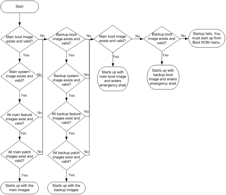
System startup process
Upon power-on, the Boot ROM image runs to initialize hardware, and then the startup software images run to start up the entire system, as shown in Figure 31.
Figure 31 System startup process
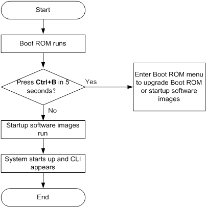
Command and hardware compatibility
Commands and descriptions for centralized devices apply to the following routers:
· MSR810/810-W/810-W-DB/810-LM/810-W-LM/810-10-PoE/810-LM-HK/810-W-LM-HK/810-LMS/810-LUS.
· MSR2600-6-X1/2600-10-X1.
· MSR 2630.
· MSR3600-28/3600-51.
· MSR3600-28-SI/3600-51-SI.
· MSR3610-X1/3610-X1-DP/3610-X1-DC/3610-X1-DP-DC.
· MSR 3610/3620/3620-DP/3640/3660.
· MSR810-LM-GL/810-W-LM-GL/830-6EI-GL/830-10EI-GL/830-6HI-GL/830-10HI-GL/2600-6-X1-GL/3600-28-SI-GL.
Commands and descriptions for distributed devices apply to the following routers:
· MSR5620.
· MSR 5660.
· MSR 5680.
Upgrade methods
|
Upgrading method |
Software types |
Remarks |
|
Use the boot-loader file command at the CLI |
· Boot ROM image · Comware images (excluding patches) |
This method is disruptive. You must reboot the entire device to complete the upgrade. |
|
Use install commands at the CLI |
Comware images |
Use this method to install new features or upgrade the boot, system, feature, or patch images. |
|
Use the Boot ROM menu |
· Boot ROM image · Comware software images |
Use this method when the device cannot start up correctly. To use this method, first connect to the console port and power cycle the device. Then press Ctrl+B at prompt to access the Boot ROM menu. For more information about upgrading software from the Boot ROM menu, see the release notes for the software version.
Upgrade an IRF fabric from the CLI instead of the Boot ROM menu, if possible. The Boot ROM menu method increases the service downtime, because it requires that you upgrade the member devices one by one. |
Upgrade restrictions and guidelines
(Distributed devices in standalone or IRF mode.) When you upgrade software, you do not need to upgrade MPUs and interface cards separately. The software images are integrated for MPUs and interface cards. The interface cards upgrade automatically when you upgrade MPUs.
Preparing for the upgrade
1. Use the display version command to verify the current Boot ROM image version and startup software version.
2. Use the release notes for the upgrade software version to evaluate the upgrade impact on your network and verify the following items:
? Software and hardware compatibility.
? Version and size of the upgrade software.
? Compatibility of the upgrade software with the current Boot ROM image and startup software image.
3. Use the release notes to verify whether the software images require a license. If licenses are required, register and activate licenses for each license-based software image. For more information about licensing, see "Managing licenses."
4. (Centralized devices in standalone mode.) Use the dir command to verify that the device has sufficient storage space for the upgrade images. If the storage space is not sufficient, delete unused files by using the delete command. For more information, see "Managing file systems."
5. (Centralized devices in IRF mode.) Use the dir command to verify that all IRF member devices have sufficient storage space for the upgrade images. If the storage space is not sufficient, delete unused files by using the delete command. For more information, see "Managing file systems."
6. (Distributed devices in standalone or IRF mode.) Use the dir command to verify that every MPU has sufficient storage space for the upgrade images. If the storage space is not sufficient, delete unused files by using the delete command. For more information, see "Managing file systems."
7. (Centralized devices in standalone mode.) Use FTP or TFTP to transfer the upgrade image file to the root directory of the default file system.
8. (Centralized devices in IRF mode.) Use FTP or TFTP to transfer the upgrade image file to the root directory of the default file system on an IRF member device.
9. (Distributed devices in standalone or IRF mode.) Download the upgrade image file to the root directory of the default file system on an MPU.
For more information about FTP and TFTP, see "Configuring FTP" or "Configuring TFTP."
Software upgrade task list
|
Tasks at a glance |
Remarks |
|
(Optional.) Preloading the Boot ROM image |
If a Boot ROM upgrade is required, you can perform this task to shorten the subsequent upgrade time. This task helps avoid upgrade problems caused by unexpected electricity failure. If you skip this task, the device upgrades the Boot ROM automatically when it upgrades the startup software images. The Boot ROM image preloaded into the Boot ROM takes effect only after you reboot the device. |
|
(Required.) Specifying startup images and completing the upgrade |
N/A |
|
(Optional.) Performing an upgrade by using install commands |
N/A |
|
(Optional.) Enabling software synchronization from the active MPU to the standby MPU at startup |
By default, software synchronization is enabled. This feature enables automatic software synchronization when the device operates in standalone mode. With software synchronization, you do not need to manually upgrade the standby MPU. To synchronize software from the global active MPU to other MPUs on an IRF fabric, use the irf auto-update enable command. |
|
(Optional.) Upgrading firmware |
N/A |
Preloading the Boot ROM image
The following matrix shows the feature and hardware compatibility:
|
Hardware |
Boot ROM image preload compatibility |
|
MSR810/810-W/810-W-DB/810-LM/810-W-LM/810-10-PoE/810-LM-HK/810-W-LM-HK/810-LMS/810-LUS |
No |
|
MSR2600-6-X1/2600-10-X1 |
Yes |
|
MSR 2630 |
Yes |
|
MSR3600-28/3600-51 |
Yes |
|
MSR3600-28-SI/3600-51-SI |
Yes |
|
MSR3610-X1/3610-X1-DP/3610-X1-DC/3610-X1-DP-DC |
Yes |
|
MSR 3610/3620/3620-DP/3640/3660 |
Yes |
|
MSR5620/5660/5680 |
Yes |
|
Hardware |
Boot ROM image preload compatibility |
|
MSR810-LM-GL |
No |
|
MSR810-W-LM-GL |
No |
|
MSR830-6EI-GL |
No |
|
MSR830-10EI-GL |
No |
|
MSR830-6HI-GL |
No |
|
MSR830-10HI-GL |
No |
|
MSR2600-6-X1-GL |
Yes |
|
MSR3600-28-SI-GL |
Yes |
To preload the Boot ROM image to Boot ROM:
|
Task |
Command |
Remarks |
|
Load the upgrade Boot ROM image to the Normal area of Boot ROM. |
·
Centralized devices in standalone mode: ·
Distributed devices in standalone
mode/centralized devices in IRF mode: ·
Distributed devices in IRF mode: |
Specify the downloaded software image file for the file-url argument. The new Boot ROM image takes effect at a reboot. |
Specifying startup images and completing the upgrade
Centralized devices in standalone mode
Perform this task in user view.
To specify startup images and complete the upgrade:
|
Step |
Command |
Remarks |
|
1. Specify main or backup startup images. |
·
Use an .ipe file for upgrade: ·
Use .bin files for upgrade: |
Upgrade files must be saved in the root directory of the storage medium. If the storage medium is partitioned, save the files to the root directory of the first partition. To avoid configuration failure, make sure no other users are configuring or managing the device. |
|
2. Save the running configuration. |
save |
This step ensures that any configuration you have made can survive a reboot. This step also ensures that the device loads the binary configuration file at reboot. Loading a binary configuration file is faster than loading a text configuration file. For more information about configuration file formats, see "Managing configuration files." |
|
3. Reboot the device. |
reboot |
At startup, the device reads the preloaded Boot ROM image to RAM, and loads the startup images. |
|
4. (Optional.) Verify the software image settings. |
display boot-loader |
Verify that the current software images are the same as the startup software images. |
Distributed devices in standalone mode
Perform this task in user view.
To specify the startup image file and complete the upgrade:
|
Step |
Command |
Remarks |
|
1. Specify main or backup startup images for the active MPU. |
·
Use an .ipe file for upgrade: ·
Use .bin files for upgrade: |
Upgrade files must be saved in the root directory of the storage medium on an MPU. If the storage medium is partitioned, save the files to the root directory of the first partition. To avoid configuration failure, make sure no other users are configuring or managing the device. |
|
2. Specify main or backup startup images for the standby MPU. |
·
Method 1 Use an .ipe file for upgrade: ·
Method 1 Use .bin files for upgrade: ·
Method 2: ·
Method 3: |
When you use method 2, make sure you understand the following requirements and upgrade results: · If an upgrade has been performed by using install commands, use the install commit command to update the main startup images on the active MPU before software synchronization. The command ensures startup image consistency between the active MPU and the standby MPU. ? If the active MPU started up with main startup images, its main startup images are synchronized to the standby MPU. This synchronization occurs regardless of whether any change has occurred to this set of startup images. ? If the active MPU started up with backup startup images, its backup startup images are synchronized to the standby MPU. This synchronization occurs regardless of whether any change has occurred to this set of startup images. · Startup image synchronization will fail if any software image being synchronized is corrupted or is not available. To avoid configuration failure, make sure no other users are configuring or managing the device. |
|
3. Save the running configuration. |
save |
This step ensures that any configuration you have made can survive a reboot. This step also ensures that the device loads the binary configuration file at reboot. Loading a binary configuration file is faster than loading a text configuration file. For more information about configuration file formats, see "Managing configuration files." |
|
4. Reboot the device. |
reboot |
At startup, the MPUs read the preloaded Boot ROM image to RAM, and load the startup images. |
|
5. (Optional.) Verify the software image settings. |
display boot-loader [ slot slot-number ] |
Verify that the current software images are the same as the startup software images. |
Centralized devices in IRF mode
Perform this task in user view.
To specify the startup image file and complete the upgrade:
|
Step |
Command |
Remarks |
|
1. Specify main or backup startup images for the master device. |
·
Use an .ipe file for upgrade: ·
Use .bin files for upgrade: |
Upgrade files must be saved in the root directory of the storage medium on an IRF member device. If the storage medium is partitioned, save the files to the root directory of the first partition. To avoid configuration failure, make sure no other users are configuring or managing the device. Do not reboot any member device during the execution of this command. Member devices might not be able to come up. |
|
2. Specify main startup images for each subordinate device. |
·
Method 1 Use an .ipe file for upgrade: ·
Method 1 Use .bin files for upgrade: ·
Method 2: |
Skip this step if you have only one device. When you use the boot-loader update command, make sure you understand the following requirements and upgrade results: · If an upgrade has been performed by using install commands, use the install commit command to update the main startup images on the master device before software synchronization. The command ensures startup image consistency among IRF member devices. · The boot-loader update command uses the main or backup startup image list for synchronization, instead of the current software images list. ? The main images list is used if the global active MPU started up with the main startup images. ? The backup image list is used if the global active MPU started up with the backup startup images. · Startup image synchronization will fail if any software image being synchronized is corrupted or is not available. To avoid configuration failure, make sure no other users are configuring or managing the device. Do not reboot any member device during the execution of this command. Member devices might not be able to come up. |
|
3. Save the running configuration. |
save |
This step ensures that any configuration you have made can survive a reboot. This step also ensures that the device loads the binary configuration file at reboot. Loading a binary configuration file is faster than loading a text configuration file. For more information about configuration file formats, see "Managing configuration files." |
|
4. Reboot the IRF 2 fabric. |
reboot |
At startup, each device reads the preloaded Boot ROM image to RAM, and loads the startup images. |
|
5. (Optional.) Verify the software image settings. |
display boot-loader [ slot slot-number ] |
Verify that the current software images are the same as the startup software images. |
Distributed devices in IRF mode
Perform this task in user view.
To specify the startup image file and complete the upgrade:
|
Step |
Command |
Remarks |
|
1. Specify main or backup startup images for the global active MPU. |
·
Use an .ipe file for upgrade: ·
Use .bin files for upgrade: |
Upgrade files must be saved in the root directory of the storage medium on an MPU in the IRF fabric. If the storage medium is partitioned, save the files to the root directory of the first partition. To avoid configuration failure, make sure no other users are configuring or managing the device. Do not reboot any card during the execution of this command. Cards might not be able to come up. |
|
2. Specify the main startup images for each standby MPU in the IRF fabric. |
·
Method 1 Use an .ipe file for upgrade: ·
Method 1 Use .bin files for upgrade: ·
Method 2: |
Skip this step if you have only one single-MPU device. When you use the boot-loader update command, make sure you understand the following requirements and upgrade results: · If an upgrade has been performed by using install commands, use the install commit command to update the main startup images on the active MPU before software synchronization. The command ensures startup image consistency between the active MPU and the standby MPU. · The boot-loader update command uses the main or backup startup image list for synchronization, instead of the current software images list. ? The main images list is used if the global active MPU started up with the main startup images. ? The backup image list is used if the global active MPU started up with the backup startup images. · Startup image synchronization will fail if any software image being synchronized is corrupted or is not available. To avoid configuration failure, make sure no other users are configuring or managing the device. Do not reboot any card during the execution of this command. Cards might not be able to come up. |
|
3. Save the running configuration. |
save |
This step ensures that any configuration you have made can survive a reboot. This step also ensures that the device loads the binary configuration file at reboot. Loading a binary configuration file is faster than loading a text configuration file. For more information about configuration file formats, see "Managing configuration files." |
|
4. Reboot the IRF fabric. |
reboot |
At startup, the MPUs read the preloaded Boot ROM image to RAM, and load the startup images. |
|
5. (Optional.) Verify the software image settings. |
display boot-loader [ chassis chassis-number [ slot slot-number ] ] |
Verify that the current software images are the same as the startup software images. |
Performing an upgrade by using install commands
Upgrade methods
Upgrade methods are automatically determined depending on the compatibility between software versions.
The following upgrade types are supported:
· Compatible upgrade—The running software version is compatible with the new software version. This upgrade type supports the upgrade methods in Table 13.
· Incompatible upgrade—The running software version is incompatible with the new software version. The two versions cannot run concurrently.
This upgrade type supports only one upgrade method (also called incompatible upgrade). This method requires a cold reboot to upgrade both control and data planes. Incompatible upgrade disrupts service if hardware redundancy is not available.
To identify the recommended upgrade methods, execute the display version comp-matrix file command.
· For a compatible upgrade, check the Upgrade Way field to identify the recommended upgrade methods.
· For an incompatible upgrade, check the end of command output for the Incompatible upgrade string.
Table 13 Upgrade methods for compatible upgrade
|
Upgrade method |
Description |
|
Incremental upgrade: · Service Upgrade · File Upgrade |
Upgrades only user mode processes that have differences between the new and old software versions. Backup processes and a main/backup process switchover are required for service continuity. · Service upgrade—Upgrades service features. The upgrade does not affect the operation of the features that are not being upgraded. · File upgrade—Upgrades hidden system program files. The system can provide services during the upgrade. |
|
Reboot |
The Reboot method disrupts service if hardware redundancy (MPU- or device-level) is not available. As a best practice, schedule the downtime carefully to minimize the upgrade impact on the services. The Reboot method reboots both the control and data planes to complete the software upgrade. (Centralized devices in standalone mode.) The Reboot method reboots member devices to complete the software upgrade. While one member device is rebooting, the other member devices can provide services. (Centralized devices in IRF mode.) The Reboot method reboots MPUs to complete the software upgrade. While one MPU is rebooting, the other MPUs can provide services. (Distributed devices in IRF mode.) |
Restrictions and guidelines
During an upgrade, use the following guidelines:
· Do not perform any of the following tasks:
? Reboot, add, or remove cards.
? Perform tasks that are irrelevant to the upgrade, such as modifying the configuration and displaying information.
? Modify, delete, or rename image files.
· Before executing the install activate and install deactivate commands, use the display system stable state command to verify that the system is stable. If the System State field displays Stable, the system is stable.
After an upgrade, you must log in to the device again before you can configure the device.
Upgrade task list
|
Tasks at a glance |
Remarks |
|
(Optional.) Decompressing an .ipe file |
To use install commands for upgrade, you must use .bin image files. If the upgrade file is an .ipe file, perform this task before you use install commands for upgrade. |
|
(Required.) Perform one of the following tasks to update software: · Installing or upgrading software images ? Installing or upgrading images except for patches |
Perform an activate operation to install new images or upgrade existing images. Perform a deactivate operation to uninstall feature or patch images. An image is added to or removed from the current software image list when it is activated or deactivated. |
|
(Optional.) Rolling back the running software images |
Perform this task to roll back running software image status after activate or deactivate operations. A commit operation deletes all rollback points. You can perform this task only before software changes are committed. |
|
(Optional.) Aborting a software activate/deactivate operation |
You can perform this task while an image is being activated or deactivated. This task is available only for service upgrade or file upgrade. |
|
(Optional.) Committing software changes |
This task updates the main startup image list with the changes. If service upgrade or file upgrade is performed, you must perform this task for the changes to take effect after a reboot. |
|
(Optional.) Verifying software images |
Perform this task to verify that the software changes are correct. |
|
(Optional.) Deleting inactive software images |
Perform this task to delete images |
Decompressing an .ipe file
Perform this task in user view.
|
Step |
Command |
|
1. (Optional.) Identify images that are included in the .ipe file. |
display install ipe-info |
|
2. Decompress the .ipe file. |
install add ipe-filename filesystem |
Installing or upgrading software images
Use one of the following methods to perform this task:
· Slot by slot—Activate all the images on one slot, and then move to the next slot.
· Image by image—Activate one image on all slots before activating another image.
Centralized devices in IRF mode:
When you install an image, you must begin with the master device.
When you upgrade an image, you must begin with a subordinate device.
Distributed devices in standalone mode:
· When you install an image, you must begin with the active MPU.
· When you upgrade an image, you must begin with the standby MPU.
Distributed devices in IRF mode:
· When you install an image, you must begin with the master. On each member device, begin with the active MPU.
· When you upgrade an image, you must begin with a subordinate device. On each member device, begin with the standby MPU.
Distributed devices in standalone or IRF mode:
When you install or upgrade images on an active MPU, the system automatically upgrades its LPUs. You do not need to upgrade software for LPUs separately.
You can install up to 32 .bin files on the device, including one boot image file, one system image file, and up to 30 feature or patch image files.
Installing or upgrading images except for patches
Perform this task in user view.
|
Step |
Command |
Remarks |
|
1. Verify that the system is stable. |
display system stable state |
The system is stable if the System State field displays Stable. For a successful upgrade, you must make sure the system is stable before you proceed to the next step. |
|
2. (Optional.) Identify the recommended upgrade method and the possible impact of the upgrade. |
·
Centralized devices in standalone mode: ·
Centralized devices in IRF mode: ·
Distributed devices in standalone mode: ·
Distributed devices in IRF mode: |
N/A |
|
3. Activate images. |
·
Centralized devices in standalone mode: ·
Centralized devices in IRF mode: ·
Distributed devices in standalone mode: ·
Distributed devices in IRF mode: |
N/A |
Installing patch images
If a system image has multiple versions of patch images, you only need to install the latest version. You do not need to uninstall older patch images before you install a new patch image.
Before activating patch images, check whether the device is already running patch images.
· If not, activate patch images.
· If yes, read the release notes to identify the functionality differences between the running patch images and the new patch images.
? If the new patch images cover all functions provided by the old patch images, activating the new patch images overwrites the old patch images. After activating the new patch images, deactivate and delete the old patch images to remove them from software image lists and release the storage space.
? If the new patch images do not cover one or more functions provided by the old patch images, activating the patch images does not affect the old patch images. The device uses both the new patch images and the old patch images. Do not deactivate or delete the old patch images.
Perform this task in user view.
|
Step |
Command |
Remarks |
|
1. Verify that the system is stable. |
display system stable state |
The system is stable if the System State field displays Stable. For a successful installation, you must make sure the system is stable before you proceed to the next step. |
|
2. Activate patch images. |
·
Centralized devices in standalone mode: ·
Centralized devices in IRF mode: ·
Distributed devices in standalone mode: ·
Distributed devices in IRF mode: |
N/A |
Uninstalling feature or patch images
You can uninstall only feature and patch images.
The uninstall operation only removes images from the current software image list. For the change to take effect after a reboot, you must perform a commit operation to remove the images from the main startup image list.
Uninstalled images are still stored on the storage medium. To permanently delete the images, execute the install remove command. For more information, see "Deleting inactive software images."
Uninstalling feature images
Perform this task in user view.
|
Step |
Command |
Remarks |
|
1. Verify that the system is stable. |
display system stable state |
The system is stable if the System State field displays Stable. For a successful uninstallation, you must make sure the system is stable before you proceed to the next step. |
|
2. Deactivate feature images. |
·
Centralized devices in standalone mode: ·
Centralized devices in IRF mode: ·
Distributed devices in standalone mode: ·
Distributed devices in IRF mode: |
N/A |
Uninstalling patch images
Perform this task in user view.
|
Step |
Command |
Remarks |
|
1. Verify that the system is stable. |
display system stable state |
The system is stable if the System State field displays Stable. For a successful uninstallation, you must make sure the system is stable before you proceed to the next step. |
|
2. Deactivate patch images. |
·
Centralized devices in standalone mode: ·
Centralized devices in IRF mode: ·
Distributed devices in standalone mode: ·
Distributed devices in IRF mode: |
N/A |
Rolling back the running software images
For each service or file upgrade performed through activate or deactivate operation, the system creates a rollback point. The rollback points are retained until the install commit command is executed
After a reboot upgrade is performed, you can roll back the running software images only to the status before any activate or deactivate operations are performed.
After a commit operation is performed, you cannot perform a rollback.
For a rollback to take effect after a reboot, you must perform a commit operation to update the main startup software image list.
To roll back the software, execute the following commands in user view:
|
Step |
Command |
Remarks |
|
1. (Optional.) Display available rollback points. |
display install rollback |
A maximum of 50 rollback points are available for service and file upgrades. The earliest rollback point is removed if this limit has been reached when a rollback point is created. |
|
2. Roll back the software. |
install rollback to { point-id | original } |
N/A |
Aborting a software activate/deactivate operation
This task is available only for service upgrade or file upgrade performed through activate or deactivate operation. After the operation is aborted, the system runs with the software images that it was running with before the operation.
|
Task |
Command |
|
Abort a software activate/deactivate operation |
· Method 1: Press Ctrl+C while a software image is being activated or deactivated. ·
Method 2: Abort a software
activate/deactivate operation in user view. |
Committing software changes
When you activate or deactivate images for an incremental upgrade, or install or uninstall patches, the main startup image list does not update with the changes. The software changes are lost at reboot. For the changes to take effect after a reboot, you must commit the changes.
Perform this task in user view.
|
Task |
Command |
Remarks |
|
Commit the software changes. |
install commit |
This command commits all software changes. |
Verifying software images
Perform this task to verify the following items:
· Integrity—Verify that the boot, system, and feature images are integral.
· Consistency—Verify that the same active images are running across the entire system.
· Software commit status—Verify that the active images are committed as needed.
If an image is not integral, consistent, or committed, use the install activate, install deactivate, and install commit commands as appropriate to resolve the issue.
Perform this task in user view.
|
Task |
Command |
|
Verify software images. |
install verify |
Deleting inactive software images
This task deletes image files permanently. You cannot use the install rollback to command to revert the operation, or use the install abort command to abort the operation.
Perform this task in user view.
|
Task |
Command |
|
Delete an inactive software image file. |
·
Centralized devices in standalone mode: ·
Centralized devices in IRF mode: ·
Distributed devices in standalone mode: ·
Distributed devices in IRF mode: |
Enabling software synchronization from the active MPU to the standby MPU at startup
This feature is available only for distributed devices in standalone mode.
To synchronize software from the global active MPU to other MPUs on an IRF fabric, use the irf auto-update enable command. For more information about software auto-update, see Virtual Technologies Configuration Guide.
When the standby MPU starts up, this feature examines its startup software images for version inconsistency with the current software images on the active MPU.
If the software versions are different, the standby MPU performs the following operations:
1. Copies the current software images of the active MPU.
2. Specifies the images as startup software images.
3. Reboots with these images.
|
|
IMPORTANT: To ensure a successful synchronization in a multiuser environment, prevent users from rebooting or swapping MPUs during the software synchronization process. You can configure the information center to output the synchronization status to configuration terminals (see Network Management and Monitoring Configuration Guide). |
To enable software synchronization from the active MPU to the standby MPU at startup:
|
Step |
Command |
Remarks |
|
1. Enter system view. |
system-view |
N/A |
|
2. Enable startup software version check for the standby MPU. |
undo version check ignore |
By default, startup software version check is enabled. |
|
3. Enable software auto-update for the standby MPU. |
version auto-update enable |
By default, software version auto-update is enabled. |
Upgrading firmware
Perform this task to upgrade firmware for components that cannot be upgraded when you upgrade Comware. Examples of these components include complex programmable logical devices (CPLDs), field programmable gate arrays (FPGAs), CPUs, and 3G modems.
Perform this task in user view.
To upgrade firmware for a component:
|
Step |
Command |
Remarks |
|
1. Upgrade the firmware. |
Centralized devices in standalone mode: firmware update [ slot slot-number ] { cpld cpld-number | cpu cpu-number | fpga fpga-number | module module-number } file filename Distributed devices in standalone mode/centralized devices in IRF mode: firmware update slot slot-number subslot subslot-number { cpld cpld-number | cpu cpu-number | fpga fpga-number | module module-number } file filename Distributed devices in IRF mode: firmware update chassis chassis-number slot slot-number subslot subslot-number { cpld cpld-number | cpu cpu-number | fpga fpga-number | module module-number } file filename |
N/A |
|
2. Power cycle the component you are upgrading. |
·
(Method 1.) Power cycle the device that
contains the card or subcard: ·
(Method 2.) Remove and reinsert the card or
subcard: · (Method 3.) Power cycle the card or subcard from the CLI: a. power-supply off b. power-supply on |
Support for these methods depends on the component model. |
Displaying and maintaining software image settings
Centralized devices in standalone mode
The commands in this section applies to centralized devices in standalone mode.
Execute display commands in any view and reset commands in user view.
|
Task |
Command |
|
Display current software images and startup software images. |
display boot-loader |
|
Display active software images. |
display install active [ verbose ] |
|
Display backup startup software images. |
display install backup [ verbose ] |
|
Display main startup software images. |
display install committed [ verbose ] |
|
Display inactive software images. |
display install inactive [ verbose ] |
|
Display the software images included in an .ipe file. |
display install ipe-info ipe-filename |
|
Display ongoing activate, deactivate, and rollback operations. |
display install job |
|
Display log entries for upgrades performed by using install commands. |
display install log [ log-id ] [ verbose ] |
|
Display software image file information. |
display install package { filename | all } [ verbose ] |
|
Display rollback point information. |
display install rollback [ point-id ] |
|
Display all software image files that include a specific component or file. |
display install which { component name | file filename } |
|
Display the recommended upgrade methods. |
display version comp-matrix file { boot filename | system filename | feature filename&<1-30> } * display version comp-matrix file ipe ipe-filename |
|
Clear log entries for upgrades performed by using install commands. |
reset install log-history oldest log-number |
|
Clear rollback points for upgrades performed by using install commands. |
reset install rollback oldest point-id |
Centralized devices in IRF mode
The commands in this section applies to centralized devices in IRF mode.
Execute display commands in any view and reset commands in user view.
|
Task |
Command |
|
Display current software images and startup software images. |
display boot-loader [ slot slot-number ] |
|
Display active software images. |
display install active [ slot slot-number ] [ verbose ] |
|
Display backup startup software images. |
display install backup [ slot slot-number ] [ verbose ] |
|
Display main startup software images. |
display install committed [ slot slot-number ] [ verbose ] |
|
Display inactive software images. |
display install inactive [ slot slot-number ] [ verbose ] |
|
Display the software images included in an .ipe file. |
display install ipe-info ipe-filename |
|
Display ongoing activate, deactivate, and rollback operations. |
display install job |
|
Display log entries for upgrades performed by using install commands. |
display install log [ log-id ] [ verbose ] |
|
Display software image file information. |
display install package { filename | all } [ verbose ] |
|
Display rollback point information. |
display install rollback [ point-id ] |
|
Display all software image files that include a specific component or file. |
display install which { component name | file filename } [ slot slot-number ] |
|
Display the recommended upgrade methods. |
display version comp-matrix file { boot filename | system filename | feature filename&<1-30> } * display version comp-matrix file ipe ipe-filename |
|
Clear log entries for upgrades performed by using install commands. |
reset install log-history oldest log-number |
|
Clear rollback points for upgrades performed by using install commands. |
reset install rollback oldest point-id |
Distributed devices in standalone mode
The commands in this section applies to distributed devices in standalone mode.
Execute display commands in any view and reset commands in user view.
|
Task |
Command |
|
Display current software images and startup software images. |
display boot-loader [ slot slot-number ] |
|
Display active software images. |
display install active [ slot slot-number ] [ verbose ] |
|
Display backup startup software images. |
display install backup [ slot slot-number ] [ verbose ] |
|
Display main startup software images. |
display install committed [ slot slot-number ] [ verbose ] |
|
Display inactive software images. |
display install inactive [ slot slot-number ] [ verbose ] |
|
Display the software images included in an .ipe file. |
display install ipe-info ipe-filename |
|
Display ongoing activate, deactivate, and rollback operations. |
display install job |
|
Display log entries for upgrades performed by using install commands. |
display install log [ log-id ] [ verbose ] |
|
Display software image file information. |
display install package { filename | all } [ verbose ] |
|
Display rollback point information. |
display install rollback [ point-id ] |
|
Display all software image files that include a specific component or file. |
display install which { component name | file filename } [ slot slot-number ] |
|
Display the recommended upgrade methods. |
display version comp-matrix file { boot filename | system filename | feature filename&<1-30> } * display version comp-matrix file ipe ipe-filename |
|
Clear log entries for upgrades performed by using install commands. |
reset install log-history oldest log-number |
|
Clear rollback points for upgrades performed by using install commands. |
reset install rollback oldest point-id |
Distributed devices in IRF mode
The commands in this section applies to distributed devices in IRF mode.
Execute display commands in any view and reset commands in user view.
|
Task |
Command |
|
Display current software images and startup software images. |
display boot-loader [ chassis chassis-number [ slot slot-number ] ] |
|
Display active software images. |
display install active [ chassis chassis-number slot slot-number ] [ verbose ] |
|
Display backup startup software images. |
display install backup [ chassis chassis-number slot slot-number ] [ verbose ] |
|
Display main startup software images. |
display install committed [ chassis chassis-number slot slot-number ] [ verbose ] |
|
Display inactive software images. |
display install inactive [ chassis chassis-number slot slot-number ] [ verbose ] |
|
Display the software images included in an .ipe file. |
display install ipe-info ipe-filename |
|
Display ongoing activate, deactivate, and rollback operations. |
display install job |
|
Display log entries for upgrades performed by using install commands. |
display install log [ log-id ] [ verbose ] |
|
Display software image file information. |
display install package { filename | all } [ verbose ] |
|
Display rollback point information. |
display install rollback [ point-id ] |
|
Display all software image files that include a specific component or file. |
display install which { component name | file filename } [ chassis chassis-number slot slot-number ] |
|
Display the recommended upgrade methods. |
display version comp-matrix file { boot filename | system filename | feature filename&<1-30> } * display version comp-matrix file ipe ipe-filename |
|
Clear log entries for upgrades performed by using install commands. |
reset install log-history oldest log-number |
|
Clear rollback points for upgrades performed by using install commands. |
reset install rollback oldest point-id |
Software upgrade examples by using the boot-loader file command
Software upgrade example (centralized devices in standalone mode)
Network requirements
As shown in Figure 32, use the file startup-a2105.ipe to upgrade software images for the device.
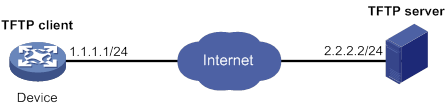
Configuration procedure
# Configure IP addresses and routes. Make sure the device and the TFTP server can reach each other. (Details not shown.)
# Configure TFTP settings on both the device and the TFTP server. (Details not shown.)
# Display information about the current software images.
<Sysname> display version
# Back up the current software images.
<Sysname> copy boot.bin boot_backup.bin
<Sysname> copy system.bin system_backup.bin
# Specify boot_backup.bin and system_backup.bin as the backup startup image files for the device.
<Sysname> boot-loader file boot flash:/boot_backup.bin system flash:/system_backup.bin backup
# Use TFTP to download the image file startup-a2105.ipe from the TFTP server to the root directory of the flash memory.
<Sysname> tftp 2.2.2.2 get startup-a2105.ipe
# Specify startup-a2105.ipe as the main startup image file.
<Sysname> boot-loader file flash:/startup-a2105.ipe main
# Verify the startup image settings.
<Sysname> display boot-loader
# Reboot the device to complete the upgrade.
<Sysname> reboot
# Verify that the device is running the correct software.
<Sysname> display version
Software upgrade example (distributed devices in standalone mode)
Network requirements
As shown in Figure 33, the device has two MPUs: one active MPU in slot 0 and one standby MPU in slot 1.
Use the file startup-a2105.ipe to upgrade software images for the device.
Configuration procedure
# Configure IP addresses and routes. Make sure the device and the TFTP server can reach each other. (Details not shown.)
# Configure TFTP settings on both the device and the TFTP server. (Details not shown.)
# Display information about the current software images.
<Sysname> display version
# Back up the current software images.
<Sysname> copy boot.bin boot_backup.bin
<Sysname> copy system.bin system_backup.bin
# Specify boot_backup.bin and system_backup.bin as the backup startup image files for both MPUs.
<Sysname> boot-loader file boot flash:/boot_backup.bin system flash:/system_backup.bin slot 0 backup
<Sysname> boot-loader file boot flash:/boot_backup.bin system flash:/system_backup.bin slot 1 backup
# Use TFTP to download the image file startup-a2105.ipe from the TFTP server to the root directory of the flash memory on the active MPU.
<Sysname> tftp 2.2.2.2 get startup-a2105.ipe
# Specify startup-a2105.ipe as the main startup image file for both MPUs.
<Sysname> boot-loader file flash:/startup-a2105.ipe slot 0 main
<Sysname> boot-loader file flash:/startup-a2105.ipe slot 1 main
# Verify the startup image settings.
<Sysname> display boot-loader
# Reboot the device to complete the upgrade.
<Sysname> reboot
# Verify that the device is running the correct software.
<Sysname> display version
Software upgrade example (centralized devices in IRF mode)
Network requirements
As shown in Figure 34, use the file startup-a2105.ipe to upgrade software images for the IRF fabric.
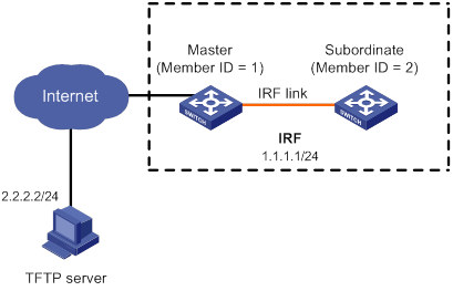
Configuration procedure
# Configure IP addresses and routes. Make sure the device and the TFTP server can reach each other. (Details not shown.)
# Configure TFTP settings on both the device and the TFTP server. (Details not shown.)
# Display information about the current software images.
<Sysname> display version
# Back up the current software images.
<Sysname> copy boot.bin boot_backup.bin
<Sysname> copy system.bin system_backup.bin
# Specify boot_backup.bin and system_backup.bin as the backup startup image files for both member devices.
<Sysname> boot-loader file boot flash:/boot_backup.bin system flash:/system_backup.bin slot 1 backup
<Sysname> boot-loader file boot flash:/boot_backup.bin system flash:/system_backup.bin slot 2 backup
# Use TFTP to download the image file startup-a2105.ipe from the TFTP server to the root directory of the flash memory on the master device.
<Sysname> tftp 2.2.2.2 get startup-a2105.ipe
# Specify startup-a2105.ipe as the main startup image file for both member devices.
<Sysname> boot-loader file flash:/startup-a2105.ipe slot 1 main
<Sysname> boot-loader file flash:/startup-a2105.ipe slot 2 main
# Verify the startup image settings.
<Sysname> display boot-loader
# Reboot the device to complete the upgrade.
<Sysname> reboot
# Verify that the device is running the correct software.
<Sysname> display version
Software upgrade example (distributed devices in IRF mode)
Network requirements
As shown in Figure 35, use the file startup-a2105.ipe to upgrade software images for the IRF fabric.
Each IRF member device has two MPUs: one in slot 0 and one in slot 1. The global active MPU is in slot 0 on the master device.
Configuration procedure
# Configure IP addresses and routes. Make sure the device and the TFTP server can reach each other. (Details not shown.)
# Configure TFTP settings on both the device and the TFTP server. (Details not shown.)
# Display information about the current software images.
<Sysname> display version
# Back up the current software images.
<Sysname> copy boot.bin boot_backup.bin
<Sysname> copy system.bin system_backup.bin
# Specify boot_backup.bin and system_backup.bin as the backup startup image files for all MPUs.
<Sysname> boot-loader file boot flash:/boot_backup.bin system flash:/system_backup.bin chassis 1 slot 0 backup
<Sysname> boot-loader file boot flash:/boot_backup.bin system flash:/system_backup.bin chassis 1 slot 1 backup
<Sysname> boot-loader file boot flash:/boot_backup.bin system flash:/system_backup.bin chassis 2 slot 0 backup
<Sysname> boot-loader file boot flash:/boot_backup.bin system flash:/system_backup.bin chassis 2 slot 1 backup
# Use TFTP to download the image file startup-a2105.ipe from the TFTP server to the root directory of the flash memory on the global active MPU.
<Sysname> tftp 2.2.2.2 get startup-a2105.ipe
# Specify startup-a2105.ipe as the main startup image file for all MPUs.
<Sysname> boot-loader file flash:/startup-a2105.ipe chassis 1 slot 0 main
<Sysname> boot-loader file flash:/startup-a2105.ipe chassis 1 slot 1 main
<Sysname> boot-loader file flash:/startup-a2105.ipe chassis 2 slot 0 main
<Sysname> boot-loader file flash:/startup-a2105.ipe chassis 2 slot 1 main
# Verify the startup image settings.
<Sysname> display boot-loader
# Reboot the IRF fabric to complete the upgrade.
<Sysname> reboot
# Verify that the IRF fabric is running the correct software.
<Sysname> display version
Software upgrade examples by using install commands (centralized devices in standalone mode)
HTTP feature upgrade example
Upgrade requirements
On the device shown in Figure 36, upgrade the HTTP feature from R0201 to R0202. The two versions are compatible.
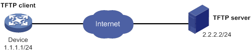
Upgrade procedure
# Download the .ipe file that contains the R0202 HTTP feature image from the TFTP server.
<Sysname> tftp 2.2.2.2 get http-r0202.ipe
% Total % Received % Xferd Average Speed Time Time Time Current
Dload Upload Total Spent Left Speed
100 256 100 256 0 0 764 0 --:--:-- --:--:-- --:--:-- 810
Writing file...Done.
# Decompress the .ipe file.
<Sysname> install add flash:/http-r0202.ipe flash:
Verifying the file flash:/http-r0202.ipe on the device...Done.
Decompressing file http-r0202.bin to flash:/http-r0202.bin.......................Done.
# Display active software images.
<Sysname> display install active
Active packages on the device:
flash:/boot-r0201.bin
flash:/system-r0201.bin
flash:/http-r0201.bin
# Identify the recommended upgrade method and the possible impact of the upgrade.
<Sysname> install activate feature flash:/http-r0202.bin test
Verifying the file flash:/http-r0202.bin on the device...Done.
Identifying the upgrade methods...Done.
Upgrade summary according to following table:
flash:/http-r0202.bin
Running Version New Version
Alpha 0201 Alpha 0202
Upgrade Way: Service Upgrade
Influenced service according to following table on the device:
flash:/http-r0202.bin
HTTP CFA
The output shows that a service upgrade is recommended and the HTTP and CFA modules will be rebooted during the upgrade process.
# Activate the new HTTP image to upgrade the HTTP feature.
<Sysname> install activate feature flash:/http-r0202.bin
Verifying the file flash:/http-r0202.bin on the device...Done.
Identifying the upgrade methods...Done.
Upgrade summary according to following table:
flash:/http-r0202.bin
Running Version New Version
Alpha 0201 Alpha 0202
Upgrade Way: Service Upgrade
Upgrading software images to compatible versions. Continue? [Y/N]: y
This operation might take several minutes, please wait......................Done.
# Verify that the new HTTP image has been activated.
<Sysname> display install active
Active packages on the device:
flash:/boot-r0201.bin
flash:/system-r0201.bin
flash:/http-r0202.bin
# Commit the software changes.
<Sysname> install commit
This operation will take several minutes, please wait...........................Done.
HTTP feature rollback example
Rollback requirement
On the device shown in Figure 36, the HTTP feature has been upgraded from R0201 to R0202 on the device. However, the software change has not been committed.
Roll back the HTTP feature from R0202 to R0201.
Rollback procedure
# Display active software images.
<Sysname> display install active
Active packages on the device:
flash:/boot-r0201.bin
flash:/system-r0201.bin
flash:/http-r0202.bin
# Display available rollback points.
<Sysname> display install rollback
Install rollback information 1 on the device:
Updating from flash:/http-r0201.bin
to flash:/http-r0202.bin.
# Roll back the HTTP feature to R0201.
<Sysname> install rollback to original
# Verify that the device is running the old HTTP image.
<Sysname> display install active
Active packages on the device:
flash:/boot-r0201.bin
flash:/system-r0201.bin
flash:/http-r0201.bin
# Commit the software changes.
<Sysname> install commit
This operation will take several minutes, please wait...........................Done.
Software upgrade examples by using install commands (distributed devices in standalone mode)
HTTP feature upgrade example
Upgrade requirements
As shown in Figure 37, the device has two MPUs. The active MPU is in slot 0. The standby MPU is in slot 1.
Upgrade the HTTP feature from R0201 to R0202. The two versions are compatible.
Upgrade procedure
# Download the .ipe file that contains the R0202 HTTP feature image from the TFTP server.
<Sysname> tftp 2.2.2.2 get http-r0202.ipe
% Total % Received % Xferd Average Speed Time Time Time Current
Dload Upload Total Spent Left Speed
100 256 100 256 0 0 764 0 --:--:-- --:--:-- --:--:-- 810
Writing file...Done.
# Decompress the .ipe file.
<Sysname> install add flash:/http-r0202.ipe flash:/
Verifying the file flash:/http-r0202.ipe on slot 0...Done.
Decompressing file http-r0202.bin to flash:/http-r0202.bin.......................Done.
# Display active software images.
<Sysname> display install active
Active packages on slot 0:
flash:/boot-r0201.bin
flash:/system-r0201.bin
flash:/http-r0201.bin
Active packages on slot 1:
flash:/boot-r0201.bin
flash:/system-r0201.bin
flash:/http-r0201.bin
# Identify the recommended upgrade methods and the possible impact of the upgrade.
<Sysname> install activate feature flash:/http-r0202.bin slot 1 test
Copying file flash:/http-r0202.bin to slot1#flash:/http-r0202.bin......Done.
Verifying the file flash:/http-r0202.bin on slot 1...Done.
Identifying the upgrade methods...Done.
Upgrade summary according to following table:
flash:/http-r0202.bin
Running Version New Version
Alpha 0201 Alpha 0202
Slot Upgrade Way
1 Service Upgrade
Influenced service according to following table on slot 1:
flash:/http-r0202.bin
HTTP CFA
<Sysname> install activate feature flash:/http-r0202.bin slot 0 test
Verifying the file flash:/http-r0202.bin on slot 0...Done.
Identifying the upgrade methods...Done.
Upgrade summary according to following table:
flash:/http-r0202.bin
Running Version New Version
Alpha 0201 Alpha 0202
Slot Upgrade Way
0 Service Upgrade
1 Service Upgrade
Influenced service according to following table on slot 0:
flash:/http-r0202.bin
HTTP CFA
The output shows that both MPUs need a service upgrade and the HTTP and CFA modules will be rebooted during the upgrade.
# Activate the new HTTP image to upgrade the HTTP feature.
<Sysname> install activate feature flash:/http-r0202.bin slot 1
flash:/http-r0202.bin already exists on slot 1.
Overwrite it?[Y/N]:y
Copying file flash:/http-r0202.bin to slot1#flash:/http-r0202.bin......Done.
Verifying the file flash:/http-r0202.bin on slot 1...Done.
Identifying the upgrade methods...Done.
Upgrade summary according to following table:
flash:/http-r0202.bin
Running Version New Version
Alpha 0201 Alpha 0202
Slot Upgrade Way
1 Service Upgrade
Upgrading software images to compatible versions. Continue? [Y/N]: y
This operation might take several minutes, please wait......................Done.
<Sysname> install activate feature flash:/http-r0202.bin slot 0
Verifying the file flash:/http-r0202.bin on slot 0...Done.
Identifying the upgrade methods...Done.
Upgrade summary according to following table:
flash:/http-r0202.bin
Running Version New Version
Alpha 0201 Alpha 0202
Slot Upgrade Way
0 Service Upgrade
1 Service Upgrade
Upgrading software images to compatible versions. Continue? [Y/N]: y
This operation might take several minutes, please wait......................Done.
# Verify that the new HTTP image has been activated.
<Sysname> display install active
Active packages on slot 0:
flash:/boot-r0201.bin
flash:/system-r0201.bin
flash:/http-r0202.bin
Active packages on slot 1:
flash:/boot-r0201.bin
flash:/system-r0201.bin
flash:/http-r0202.bin
# Commit the software changes.
<Sysname> install commit
This operation will take several minutes, please wait...........................Done.
HTTP feature rollback example
Rollback requirement
As shown in Figure 37, the device has two MPUs. The active MPU is in slot 0. The standby MPU is in slot 1.
The HTTP feature has been upgraded from R0201 to R0202. However, the software change has not been committed.
Roll back the HTTP feature from R0202 to R0201.
Rollback procedure
# Display active software images.
<Sysname> display install active
Active packages on slot 0:
flash:/boot-r0201.bin
flash:/system-r0201.bin
flash:/http-r0202.bin
Active packages on slot 1:
flash:/boot-r0201.bin
flash:/system-r0201.bin
flash:/http-r0202.bin
# Display available rollback points.
<Sysname> display install rollback
Install rollback information 1 on slot 0:
Updating from flash:/http-r0201.bin
to flash:/http-r0202.bin.
Install rollback information 2 on slot 1:
Updating from flash:/http-r0201.bin
to flash:/http-r0202.bin.
# Roll back the HTTP feature to R0201.
<Sysname> install rollback to original
# Verify that the MPUs are running the old HTTP image.
<Sysname> display install active
Active packages on slot 0:
flash:/boot-r0201.bin
flash:/system-r0201.bin
flash:/http-r0201.bin
Active packages on slot 1:
flash:/boot-r0201.bin
flash:/system-r0201.bin
flash:/http-r0201.bin
# Commit the software changes.
<Sysname> install commit
This operation will take several minutes, please wait...........................Done.
Software upgrade examples by using install commands (centralized devices in IRF mode)
HTTP feature upgrade example
Upgrade requirements
As shown in Figure 38, the IRF fabric has two members.
Upgrade the HTTP feature from R0201 to R0202. The two versions are compatible.
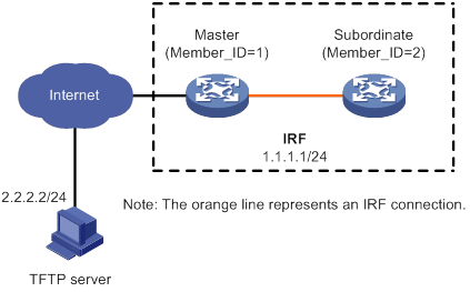
Upgrade procedure
# Download the .ipe file that contains the R0202 HTTP feature image from the TFTP server.
<Sysname> tftp 2.2.2.2 get http-r0202.ipe
% Total % Received % Xferd Average Speed Time Time Time Current
Dload Upload Total Spent Left Speed
100 256 100 256 0 0 764 0 --:--:-- --:--:-- --:--:-- 810
Writing file...Done.
# Decompress the .ipe file.
<Sysname> install add flash:/http-r0202.ipe flash:
Verifying the file flash:/http-r0202.ipe on slot 1...Done.
Decompressing file http-r0202.bin to flash:/http-r0202.bin.......................Done.
# Display active software images.
<Sysname> display install active
Active packages on slot 1:
flash:/boot-r0201.bin
flash:/system-r0201.bin
flash:/http-r0201.bin
Active packages on slot 2:
flash:/boot-r0201.bin
flash:/system-r0201.bin
flash:/http-r0201.bin
# Identify the recommended upgrade methods and the possible impact of the upgrade.
<Sysname> install activate feature flash:/http-r0202.bin slot 2 test
Copying file flash:/http-r0202.bin to slot2#flash:/http-r0202.bin......Done.
Verifying the file flash:/http-r0202.bin on slot 2...Done.
Identifying the upgrade methods...Done.
Upgrade summary according to following table:
flash:/http-r0202.bin
Running Version New Version
Alpha 0201 Alpha 0202
Slot Upgrade Way
2 Service Upgrade
Influenced service according to following table on slot 2:
flash:/http-r0202.bin
HTTP CFA
<Sysname> install activate feature flash:/http-r0202.bin slot 1 test
Verifying the file flash:/http-r0202.bin on slot 1...Done.
Identifying the upgrade methods...Done.
Upgrade summary according to following table:
flash:/http-r0202.bin
Running Version New Version
Alpha 0201 Alpha 0202
Slot Upgrade Way
1 Service Upgrade
Influenced service according to following table on slot 1:
flash:/http-r0202.bin
HTTP CFA
The output shows that both members need a service upgrade and the HTTP and CFA modules will be rebooted during the upgrade.
# Activate the new HTTP image to upgrade the HTTP feature.
<Sysname> install activate feature flash:/http-r0202.bin slot 2
Verifying the file flash:/http-r0202.bin on slot 1...Done.
flash:/http-r0202.bin already exists on slot 2.
Overwrite it?[Y/N]:y
Copying file flash:/http-r0202.bin to slot2#flash:/http-r0202.bin......Done.
Verifying the file flash:/http-r0202.bin on slot 2...Done.
Identifying the upgrade methods...Done.
Upgrade summary according to following table:
flash:/http-r0202.bin
Running Version New Version
Alpha 0201 Alpha 0202
Slot Upgrade Way
2 Service Upgrade
Upgrading software images to compatible versions. Continue? [Y/N]: y
This operation might take several minutes, please wait......................Done.
<Sysname> install activate feature flash:/http-r0202.bin slot 1
Verifying the file flash:/http-r0202.bin on slot 1...Done.
Identifying the upgrade methods...Done.
Upgrade summary according to following table:
flash:/http-r0202.bin
Running Version New Version
Alpha 0201 Alpha 0202
Slot Upgrade Way
1 Service Upgrade
Upgrading software images to compatible versions. Continue? [Y/N]: y
This operation might take several minutes, please wait......................Done.
# Display active software images.
<Sysname> display install active
Active packages on slot 1:
flash:/boot-r0201.bin
flash:/system-r0201.bin
flash:/http-r0202.bin
Active packages on slot 2:
flash:/boot-r0201.bin
flash:/system-r0201.bin
flash:/http-r0202.bin
# Commit the software changes.
<Sysname> install commit
This operation will take several minutes, please wait...........................Done.
HTTP feature rollback example
Rollback requirement
As shown in Figure 38, the IRF fabric has two members. The HTTP feature has been upgraded from R0201 to R0202. However, the software change has not been committed.
Roll back the HTTP feature from R0202 to R0201.
Rollback procedure
# Display active software images.
<Sysname> display install active
Active packages on slot 1:
flash:/boot-r0201.bin
flash:/system-r0201.bin
flash:/http-r0202.bin
Active packages on slot2:
flash:/boot-r0201.bin
flash:/system-r0201.bin
flash:/http-r0202.bin
# Display available rollback points.
<Sysname> display install rollback
Install rollback information 1 on slot 1:
Updating from flash:/http-r0201.bin
to flash:/http-r0202.bin.
Install rollback information 2 on slot 2:
Updating from flash:/http-r0201.bin
to flash:/http-r0202.bin.
# Roll back the HTTP feature to R0201.
<Sysname> install rollback to original
# Verify that the IRF members are running the old HTTP image.
<Sysname> display install active
Active packages on slot 1:
flash:/boot-r0201.bin
flash:/system-r0201.bin
flash:/http-r0201.bin
Active packages on slot 2:
flash:/boot-r0201.bin
flash:/system-r0201.bin
flash:/http-r0201.bin
# Commit the software changes.
<Sysname> install commit
This operation will take several minutes, please wait...........................Done.
Software upgrade examples by using install commands (distributed devices in IRF mode)
HTTP feature upgrade example
Upgrade requirements
As shown in Figure 39, the IRF fabric has two members. Each member has one MPU in slot 0 (active MPU) and one MPU in slot 1 (standby MPU).
Upgrade the HTTP feature from R0201 to R0202. The two versions are compatible.
Upgrade procedure
# Download the .ipe file that contains the R0202 HTTP feature image from the TFTP server.
<Sysname> tftp 2.2.2.2 get http-r0202.ipe
% Total % Received % Xferd Average Speed Time Time Time Current
Dload Upload Total Spent Left Speed
100 256 100 256 0 0 764 0 --:--:-- --:--:-- --:--:-- 810
Writing file...Done.
# Decompress the .ipe file.
<Sysname> install add flash:/http-r0202.ipe flash:
Verifying the file flash:/http-r0202.ipe on slot 1...Done.
Decompressing file http-r0202.bin to flash:/http-r0202.bin.......................Done.
# Display active software images.
<Sysname> display install active
Active packages on chassis 1 slot 0:
flash:/boot-r0201.bin
flash:/system-r0201.bin
flash:/http-r0201.bin
Active packages on chassis 1 slot 1:
flash:/boot-r0201.bin
flash:/system-r0201.bin
flash:/http-r0201.bin
Active packages on chassis 2 slot 0:
flash:/boot-r0201.bin
flash:/system-r0201.bin
flash:/http-r0201.bin
Active packages on chassis 2 slot 1:
flash:/boot-r0201.bin
flash:/system-r0201.bin
flash:/http-r0201.bin
# Identify the recommended upgrade methods and the possible impact of the upgrade.
<Sysname> install activate feature flash:/http-r0202.bin chassis 2 slot 1 test
Copying file flash:/http-r0202.bin to chassis2#slot1#flash:/http-r0202.bin......Done.
Verifying the file flash:/http-r0202.bin on chassis 2 slot 1...Done.
Identifying the upgrade methods...Done.
Upgrade summary according to following table:
flash:/http-r0202.bin
Running Version New Version
Alpha 0201 Alpha 0202
Chassis Slot Upgrade Way
2 0 Service Upgrade
2 1 Service Upgrade
Influenced service according to following table on chassis 2 slot 0:
flash:/http-r0202.bin
HTTP CFA
Influenced service according to following table on chassis 2 slot 1:
flash:/http-r0202.bin
HTTP CFA
<Sysname> install activate feature flash:/http-r0202.bin chassis 2 slot 0 test
Copying file flash:/http-r0202.bin to chassis2#slot0#flash:/http-r0202.bin......Done.
Verifying the file flash:/http-r0202.bin on chassis 2 slot 0...Done.
Identifying the upgrade methods...Done.
Upgrade summary according to following table:
flash:/http-r0202.bin
Running Version New Version
Alpha 0201 Alpha 0202
Chassis Slot Upgrade Way
2 0 Service Upgrade
Influenced service according to following table on chassis 2 slot 0:
flash:/http-r0202.bin
HTTP CFA
<Sysname> install activate feature flash:/http-r0202.bin chassis 1 slot 1 test
Copying file flash:/http-r0202.bin to chassis1#slot1#flash:/http-r0202.bin......Done.
Verifying the file flash:/http-r0202.bin on chassis 1 slot 1...Done.
Identifying the upgrade methods...Done.
Upgrade summary according to following table:
flash:/http-r0202.bin
Running Version New Version
Alpha 0201 Alpha 0202
Chassis Slot Upgrade Way
1 0 Service Upgrade
1 1 Service Upgrade
Influenced service according to following table on chassis 1 slot 0:
flash:/http-r0202.bin
HTTP CFA
Influenced service according to following table on chassis 1 slot 1:
flash:/http-r0202.bin
HTTP CFA
<Sysname> install activate feature flash:/http-r0202.bin chassis 1 slot 0 test
Verifying the file flash:/http-r0202.bin on chassis 1 slot 0...Done.
Identifying the upgrade methods...Done.
Upgrade summary according to following table:
flash:/http-r0202.bin
Running Version New Version
Alpha 0201 Alpha 0202
Chassis Slot Upgrade Way
1 0 Service Upgrade
Influenced service according to following table on chassis 1 slot 0:
flash:/http-r0202.bin
HTTP CFA
The output shows that all the MPUs need a service upgrade and the HTTP and CFA modules will be rebooted during the upgrade.
# Activate the new HTTP image to upgrade the HTTP feature.
<Sysname> install activate feature flash:/http-r0202.bin chassis 2 slot 1
Verifying the file flash:/http-r0202.bin on chassis 2 slot 1...Done.
flash:/http-r0202.bin already exists on chassis 2 slot 1.
Overwrite it?[Y/N]:y
Copying file flash:/http-r0202.bin to chassis2#slot1#flash:/http-r0202.bin......Done.
Verifying the file flash:/http-r0202.bin on chassis 2 slot 1...Done.
Identifying the upgrade methods...Done.
Upgrade summary according to following table:
flash:/http-r0202.bin
Running Version New Version
Alpha 0201 Alpha 0202
Chassis Slot Upgrade Way
2 0 Service Upgrade
2 1 Service Upgrade
Upgrading software images to compatible versions. Continue? [Y/N]: y
This operation might take several minutes, please wait......................Done.
<Sysname> install activate feature flash:/http-r0202.bin chassis 2 slot 0
flash:/http-r0202.bin already exists on chassis 2 slot 0.
Overwrite it?[Y/N]:y
Copying file flash:/http-r0202.bin to chassis2#slot0#flash:/http-r0202.bin......Done.
Verifying the file flash:/http-r0202.bin on chassis 2 slot 0...Done.
Identifying the upgrade methods...Done.
Upgrade summary according to following table:
flash:/http-r0202.bin
Running Version New Version
Alpha 0201 Alpha 0202
Chassis Slot Upgrade Way
2 0 Service Upgrade
Upgrading software images to compatible versions. Continue? [Y/N]: y
This operation might take several minutes, please wait......................Done.
<Sysname> install activate feature flash:/http-r0202.bin chassis 1 slot 1
flash:/http-r0202.bin already exists on chassis 1 slot 1.
Overwrite it?[Y/N]:y
Copying file flash:/http-r0202.bin to chassis1#slot1#flash:/http-r0202.bin......Done.
Verifying the file flash:/http-r0202.bin on chassis 1 slot 1...Done.
Identifying the upgrade methods...Done.
Upgrade summary according to following table:
flash:/http-r0202.bin
Running Version New Version
Alpha 0201 Alpha 0202
Chassis Slot Upgrade Way
1 0 Service Upgrade
1 1 Service Upgrade
Upgrading software images to compatible versions. Continue? [Y/N]: y
This operation might take several minutes, please wait......................Done.
<Sysname> install activate feature flash:/http-r0202.bin chassis 1 slot 0
Verifying the file flash:/http-r0202.bin on chassis 1 slot 0...Done.
Identifying the upgrade methods...Done.
Upgrade summary according to following table:
flash:/http-r0202.bin
Running Version New Version
Alpha 0201 Alpha 0202
Chassis Slot Upgrade Way
1 0 Service Upgrade
Upgrading software images to compatible versions. Continue? [Y/N]: y
This operation might take several minutes, please wait......................Done.
# Verify that the new HTTP image has been activated.
<Sysname> display install active
Active packages on chassis 1 slot 0:
flash:/boot-r0201.bin
flash:/system-r0201.bin
flash:/http-r0202.bin
Active packages on chassis 1 slot 1:
flash:/boot-r0201.bin
flash:/system-r0201.bin
flash:/http-r0202.bin
Active packages on chassis 2 slot 0:
flash:/boot-r0201.bin
flash:/system-r0201.bin
flash:/http-r0202.bin
Active packages on chassis 2 slot 1:
flash:/boot-r0201.bin
flash:/system-r0201.bin
flash:/http-r0202.bin
# Commit the software changes.
<Sysname> install commit
This operation will take several minutes, please wait...........................Done.
HTTP feature rollback example
Rollback requirement
As shown in Figure 39, the IRF fabric has two members. Each member has one MPU in slot 0 (active MPU) and one MPU in slot 1 (standby MPU).
The HTTP feature has been upgraded from R0201 to R0202. However, the software change has not been committed.
Roll back the HTTP feature from R0202 to R0201.
Rollback procedure
# Display active software images.
<Sysname> display install active
Active packages on chassis 1 slot 0:
flash:/boot-r0201.bin
flash:/system-r0201.bin
flash:/http-r0202.bin
Active packages on chassis 1 slot 1:
flash:/boot-r0201.bin
flash:/system-r0201.bin
flash:/http-r0202.bin
Active packages on chassis 2 slot 0:
flash:/boot-r0201.bin
flash:/system-r0201.bin
flash:/http-r0202.bin
Active packages on chassis 2 slot 1:
flash:/boot-r0201.bin
flash:/system-r0201.bin
flash:/http-r0202.bin
# Display available rollback points.
<Sysname> display install rollback
Install rollback information 1 on chassis 1 slot 0:
Updating from flash:/http-r0201.bin
to flash:/http-r0202.bin.
Install rollback information 2 on chassis 1 slot 1:
Updating from flash:/http-r0201.bin
to flash:/http-r0202.bin.
Install rollback information 3 on chassis 2 slot 0:
Updating from flash:/http-r0201.bin
to flash:/http-r0202.bin.
Install rollback information 4 on chassis 2 slot 1:
Updating from flash:/http-r0201.bin
to flash:/http-r0202.bin.
# Roll back the HTTP feature to R0201.
<Sysname> install rollback to original
# Verify that the MPUs are running the old HTTP image.
<Sysname> display install active
Active packages on chassis 1 slot 0:
flash:/boot-r0201.bin
flash:/system-r0201.bin
flash:/http-r0201.bin
Active packages on chassis 1 slot 1:
flash:/boot-r0201.bin
flash:/system-r0201.bin
flash:/http-r0201.bin
Active packages on chassis 2 slot 0:
flash:/boot-r0201.bin
flash:/system-r0201.bin
flash:/http-r0201.bin
Active packages on chassis 2 slot 1:
flash:/boot-r0201.bin
flash:/system-r0201.bin
flash:/http-r0201.bin
# Commit the software changes.
<Sysname> install commit
This operation will take several minutes, please wait...........................Done.
Performing an ISSU
Unless otherwise stated, the term "upgrade" refers to both software upgrade and downgrade in ISSU.
Overview
The In-Service Software Upgrade (ISSU) feature upgrades the Comware software with a minimum amount of downtime.
ISSU is implemented on the basis of the following design advantages:
· Separation of service features from basic functions—Device software is segmented into boot, system, and feature images. The images can be upgraded individually.
· Independence between service features—Features run independently. One feature can be added or upgraded without affecting the operation of the system or other features.
· Support for hotfix—Patch images are available to fix system bugs without a system reboot.
· Hardware redundancy—On a dual-MPU device or a multichassis IRF fabric, one MPU or member device can be upgraded while other MPUs or member devices are providing services.
For more information about images, see "Upgrading software."
ISSU methods
ISSU methods are automatically determined depending on the compatibility between software versions.
ISSU supports the following upgrade types:
· Compatible upgrade—The running software version is compatible with the new software version. This upgrade type supports the ISSU methods in Table 14.
· Incompatible upgrade—The running software version is incompatible with the new software version. The two versions cannot run concurrently.
This upgrade type supports only one upgrade method (also called incompatible upgrade). This method requires a cold reboot to upgrade both control and data planes. Incompatible upgrade disrupts service if hardware redundancy is not available.
For information about identifying the ISSU method, see "Identifying the ISSU method."
Table 14 ISSU methods for compatible upgrade
|
ISSU method |
Description |
|
Incremental upgrade: · Service Upgrade · File Upgrade |
Upgrades only user mode processes that have differences between the new and old software versions. Backup processes and a main/backup process switchover are required for service continuity. · Service upgrade—Upgrades service features. The upgrade does not affect the operation of the features that are not being upgraded. · File upgrade—Upgrades hidden system program files. The system can provide services during the upgrade. |
|
ISSU Reboot |
Reboots CPUs to complete software upgrade. During the reboot, the data plane can still forward traffic. This method is typically used for critical processes, including kernel mode processes and user mode processes that cannot be upgraded by using incremental upgrade. This method saves all hardware data, configuration settings, running data, and status information to memory before rebooting CPUs. For services that require regular communication with their peers, this method uses protocol agents to maintain their connectivity and status. After the reboot, all data is restored to CPU. |
|
Reboot |
The Reboot method disrupts service if hardware redundancy (MPU- or device-level) is not available. As a best practice, schedule the downtime carefully to minimize the upgrade impact on the services. The Reboot method reboots both the control and data planes to complete the software upgrade. (Centralized devices in standalone mode.) The Reboot method reboots member devices to complete the software upgrade. While one member device is rebooting, the other member devices can provide services. (Centralized devices in IRF mode.) The Reboot method reboots MPUs to complete the software upgrade. While one MPU is rebooting, the other MPUs can provide services. (Distributed devices in IRF mode.) |
ISSU commands
ISSU includes the install and issu command sets. The device supports only the install command set.
Command and hardware compatibility
Commands and descriptions for centralized devices apply to the following routers:
· MSR810/810-W/810-W-DB/810-LM/810-W-LM/810-10-PoE/810-LM-HK/810-W-LM-HK/810-LMS/810-LUS.
· MSR2600-6-X1/2600-10-X1.
· MSR 2630.
· MSR3600-28/3600-51.
· MSR3600-28-SI/3600-51-SI.
· MSR3610-X1/3610-X1-DP/3610-X1-DC/3610-X1-DP-DC.
· MSR 3610/3620/3620-DP/3640/3660.
Commands and descriptions for distributed devices apply to the following routers:
· MSR5620.
· MSR 5660.
· MSR 5680.
Preparing for ISSU
To perform a successful ISSU, make sure all the preparation requirements are met.
Identifying availability of ISSU and licensing requirements
Read the software release notes to identify the following items:
· Support of the device for ISSU between the current software version and the new software version.
· Licensing requirements for the upgrade software images.
If the upgrade software images require licenses, make sure the device has the required licenses before ISSU. For more information about license installation, see "Managing licenses."
Verifying the device operating status
Use the display device command to verify that no cards or member devices are in Fault state.
Preparing the upgrade images
1. Use the dir command to verify that sufficient storage space is available for the upgrade images. If the storage space is not sufficient, delete unused files by using the delete /unreserved file-url command. If the files to be deleted will be used, back up the files before deleting them. You will be unable to restore a deleted file if the /unreserved keyword is used. For more information, see "Managing file systems."
|
|
NOTE: · On distributed devices, make sure every MPU has sufficient storage space for the upgrade image. · On an IRF fabric of centralized devices, make sure all members have sufficient storage space for the upgrade images. |
2. Use FTP or TFTP to transfer upgrade image files (in .bin or .ipe) to the root directory of any file system on the device or IRF fabric.
Identifying the ISSU method
1. Execute the display version comp-matrix file command for the upgrade image version compatibility information.
2. Check the Version compatibility list field.
? If the running software version is in the list, a compatible upgrade is required.
? If the running software version is not in the list, an incompatible upgrade is required.
3. Identify the recommended ISSU method.
? If a compatible upgrade is required, check the Upgrade Way field to identify the recommended ISSU method. For more information about ISSU methods, see Table 14.
? If an incompatible upgrade is required, check the end of command output for the Incompatible upgrade string.
Verifying feature status
For service continuity during ISSU, configure the following feature settings:
|
Feature |
Setting requirements |
|
GR/NSR |
Enable GR or NSR for protocols including LDP, RSVP, OSPF, ISIS, BGP, and FSPF. |
|
BFD |
Disable BFD for protocols including LDP, RSVP, OSPF, ISIS, RIP, BGP, VRRP, and NQA. |
|
Ethernet link aggregation |
Use the long LACP timeout interval (the lacp period short command is not configured) on all member ports in dynamic aggregation groups. |
|
IRF |
To perform a compatible upgrade, configure the irf mac-address persistent timer or irf mac-address persistent always command. |
For an ISSU Reboot upgrade on an IRF fabric formed by a single centralized device, also verify that the following features are disabled:
|
Feature |
Remarks |
|
Spanning tree feature |
If the spanning tree feature is enabled, service discontinuity might occur during the upgrade because the feature advertises the network topology change. |
|
Dynamic Ethernet link aggregation |
During an ISSU reboot, only static aggregation is supported. Dynamic aggregate interfaces might not be able to provide services. |
|
CFD |
If CFD is enabled, the CFD CC feature will be disabled during an ISSU reboot, which results in traffic abnormality. |
|
DLDP |
If DLDP is enabled, the peer device might consider a link a unidirectional link and shut down the port because it cannot receive probe packets. |
|
Loop detection |
If loop detection is enabled, the peer device might enable looped ports because of false loop removal detection. |
Understanding ISSU guidelines
ISSU can maintain service continuity only when the following conditions are met:
· The IRF fabric has multiple members and uses the ring topology. (Centralized devices in IRF mode.) (Distributed devices in IRF mode.)
· In standalone mode or in a single-chassis IRF fabric, the device has two MPUs that are operating correctly. (Distributed devices in standalone or IRF mode.)
· In a multichassis IRF fabric, each IRF member has a minimum of one MPU that is operating correctly. (Distributed devices in IRF mode.)
|
|
IMPORTANT: If hardware redundancy is not available, service discontinuity is not avoidable. Make sure you understand the impact of the upgrade on the network. |
During an ISSU, use the following guidelines:
· In a multiuser environment, make sure no other administrators access the device while you are performing the ISSU.
· Do not perform any of the following tasks during an ISSU:
? Reboot, add, or remove cards.
? Execute commands that are irrelevant to the ISSU.
? Modify, delete, or rename image files.
· Before executing the install activate and install deactivate commands, use the display system stable state command to verify that the system is stable. If the System State field displays Stable, the system is stable.
After an ISSU, you must log in to the device again before you can configure the device.
On centralized devices in standalone or IRF mode, the following protocols will recalculate topology after an ISSU reboot if a peer keepalive timeout has occurred:
· Multicast protocols—PIM, IGMP, MLD, IGMP snooping, and MLD snooping.
· Routing protocols—OSPF, IS-IS, and BGP.
· MPLS protocols—LDP and RSVP.
· FCoE—FIP and FSPF.
Adjusting and saving the running configuration
1. Remove the configured commands that the new software version does not support.
2. Use the save command to save the running configuration.
Logging in to the device through the console port
Log in to the device through the console port after you finish all the preparation tasks and read all the ISSU guidelines. If you use Telnet or SSH, you might be disconnected from the device before the ISSU is completed.
Performing an ISSU by using install commands
ISSU task list
|
Tasks at a glance |
Remarks |
|
(Optional.) Decompressing an .ipe file |
To use install commands for upgrade, you must use .bin image files. If the upgrade file is an .ipe file, perform this task before you use install commands for upgrade. |
|
(Required.) Perform one of the following tasks to update software: · Installing or upgrading software images ? Installing or upgrading images except for patches |
Perform an activate operation to install new images or upgrade existing images. Perform a deactivate operation to uninstall feature or patch images. An image is added to or removed from the current software image list when it is activated or deactivated. |
|
(Optional.) Rolling back the running software images |
Perform this task to roll back running software image status after activate or deactivate operations. A commit operation deletes all rollback points. You can perform this task only before software changes are committed. |
|
(Optional.) Aborting a software activate/deactivate operation |
You can perform this task while an image is being activated or deactivated. This task is available only for service upgrade or file upgrade. |
|
(Optional.) Committing software changes |
This task updates the main startup image list with the changes. If service upgrade or file upgrade is performed, you must perform this task for the changes to take effect after a reboot. |
|
(Optional.) Verifying software images |
Perform this task to verify that the software changes are correct. |
|
(Optional.) Deleting inactive software images |
Perform this task to delete images |
Decompressing an .ipe file
Perform this task in user view.
|
Step |
Command |
|
1. (Optional.) Identify images that are included in the .ipe file. |
display install ipe-info |
|
2. Decompress the .ipe file. |
install add ipe-filename filesystem |
Installing or upgrading software images
Use one of the following methods to perform this task:
· Slot by slot—Activate all the images on one slot, and then move to the next slot.
· Image by image—Activate one image on all slots before activating another image.
Centralized devices in IRF mode:
When you install an image, you must begin with the master device.
When you upgrade an image, you must begin with a subordinate device.
Distributed devices in standalone mode:
· When you install an image, you must begin with the active MPU.
· When you upgrade an image, you must begin with the standby MPU.
Distributed devices in IRF mode:
· When you install an image, you must begin with the master. On each member device, begin with the active MPU.
· When you upgrade an image, you must begin with a subordinate device. On each member device, begin with the standby MPU.
Distributed devices in standalone or IRF mode:
When you install or upgrade images on an active MPU, the system automatically upgrades its LPUs. You do not need to upgrade software for LPUs separately.
Installing or upgrading images except for patches
Perform this task in user view.
|
Step |
Command |
Remarks |
|
1. Verify that the system is stable. |
display system stable state |
The system is stable if the System State field displays Stable. For a successful ISSU, you must make sure the system is stable before you proceed to the next step. |
|
2. (Optional.) Identify the recommended ISSU method and the possible impact of the upgrade. |
·
Centralized devices in standalone mode: ·
Centralized devices in IRF mode: ·
Distributed devices in standalone mode: ·
Distributed devices in IRF mode: |
N/A |
|
3. Activate images. |
·
Centralized devices in standalone mode: ·
Centralized devices in IRF mode: ·
Distributed devices in standalone mode: ·
Distributed devices in IRF mode: |
N/A |
Installing patch images
If a system image has multiple versions of patch images, you only need to install the latest version. You do not need to uninstall older patch images before you install a new patch image.
Perform this task in user view.
|
Step |
Command |
Remarks |
|
1. Verify that the system is stable. |
display system stable state |
The system is stable if the System State field displays Stable. For a successful installation, you must make sure the system is stable before you proceed to the next step. |
|
2. Activate patch images. |
·
Centralized devices in standalone mode: ·
Centralized devices in IRF mode: ·
Distributed devices in standalone mode: ·
Distributed devices in IRF mode: |
N/A |
Uninstalling feature or patch images
You can uninstall only feature and patch images.
The uninstall operation only removes images from the current software image list. For the change to take effect after a reboot, you must perform a commit operation to remove the images from the main startup image list.
Uninstalled images are still stored on the storage medium. To permanently delete the images, execute the install remove command. For more information, see "Deleting inactive software images."
Uninstalling feature images
Perform this task in user view.
|
Step |
Command |
Remarks |
|
1. Verify that the system is stable. |
display system stable state |
The system is stable if the System State field displays Stable. For a successful uninstallation, you must make sure the system is stable before you proceed to the next step. |
|
2. Deactivate feature images. |
·
Centralized devices in standalone mode: ·
Centralized devices in IRF mode: ·
Distributed devices in standalone mode: ·
Distributed devices in IRF mode: |
N/A |
Uninstalling patch images
Perform this task in user view.
|
Step |
Command |
Remarks |
|
1. Verify that the system is stable. |
display system stable state |
The system is stable if the System State field displays Stable. For a successful uninstallation, you must make sure the system is stable before you proceed to the next step. |
|
2. Deactivate patch images. |
·
Centralized devices in standalone mode: ·
Centralized devices in IRF mode: ·
Distributed devices in standalone mode: ·
Distributed devices in IRF mode: |
N/A |
Rolling back the running software images
For each service or file upgrade performed through activate or deactivate operation, the system creates a rollback point. The rollback points are retained until any of the following events occur:
· An ISSU reboot or reboot upgrade is performed.
· The install commit command is executed.
After an ISSU reboot or reboot upgrade is performed, you can roll back the running software images only to the status before any activate or deactivate operations are performed.
After a commit operation is performed, you cannot perform a rollback.
For a rollback to take effect after a reboot, you must perform a commit operation to update the main startup software image list.
To roll back the software, execute the following commands in user view:
|
Step |
Command |
Remarks |
|
1. (Optional.) Display available rollback points. |
display install rollback |
A maximum of 50 rollback points are available for service and file upgrades. The earliest rollback point is removed if this limit has been reached when a rollback point is created. |
|
2. Roll back the software. |
install rollback to { point-id | original } |
N/A |
Aborting a software activate/deactivate operation
This task is available only for service upgrade or file upgrade performed through activate or deactivate operation. After the operation is aborted, the system runs with the software images that it was running with before the operation.
|
Task |
Command |
|
Aborting a software activate/deactivate operation |
· Method 1: Press Ctrl+C while a software image is being activated or deactivated. ·
Method 2: Abort a software
activate/deactivate operation in user view. |
Committing software changes
When you activate or deactivate images for an incremental upgrade, or install or uninstall patches, the main startup image list does not update with the changes. The software changes are lost at reboot. For the changes to take effect after a reboot, you must commit the changes.
Perform this task in user view.
|
Task |
Command |
Remarks |
|
Commit the software changes. |
install commit |
This command commits all software changes. |
Verifying software images
Perform this task to verify the following items:
· Integrity—Verify that the boot, system, and feature images are integral.
· Consistency—Verify that the same active images are running across the entire system.
· Software commit status—Verify that the active images are committed as needed.
If an image is not integral, consistent, or committed, use the install activate, install deactivate, and install commit commands as appropriate to resolve the issue.
Perform this task in user view.
|
Task |
Command |
|
Verify software images. |
install verify |
Deleting inactive software images
This task delete image files permanently. You cannot use the install rollback to command to revert the operation, or use the install abort command to abort the operation.
Perform this task in user view.
|
Task |
Command |
|
Delete an inactive software image file. |
·
Centralized devices in standalone mode: ·
Centralized devices in IRF mode: ·
Distributed devices in standalone mode: ·
Distributed devices in IRF mode: |
Displaying and maintaining ISSU
Centralized devices in standalone mode
The commands in this section applies to centralized devices in standalone mode.
Execute display commands in any view and reset commands in user view.
|
Task |
Command |
|
Display active software images. |
display install active [ verbose ] |
|
Display backup startup software images. |
display install backup [ verbose ] |
|
Display main startup software images. |
display install committed [ verbose ] |
|
Display inactive software images. |
display install inactive [ verbose ] |
|
Display the software images included in an .ipe file. |
display install ipe-info ipe-filename |
|
Display ongoing ISSU activate, deactivate, and rollback operations. |
display install job |
|
Display ISSU log entries. |
display install log [ log-id ] [ verbose ] |
|
Display software image file information. |
display install package { filename | all } [ verbose ] |
|
Display rollback point information. |
display install rollback [ point-id ] |
|
Display all software image files that include a specific component or file. |
display install which { component name | file filename } |
|
Display version compatibility information and identify the upgrade method. |
display version comp-matrix |
|
Clear ISSU log entries. |
reset install log-history oldest log-number |
|
Clear ISSU rollback points. |
reset install rollback oldest point-id |
Centralized devices in IRF mode
The commands in this section applies to centralized devices in IRF mode.
Execute display commands in any view and reset commands in user view.
|
Task |
Command |
|
Display active software images. |
display install active [ slot slot-number ] [ verbose ] |
|
Display backup startup software images. |
display install backup [ slot slot-number ] [ verbose ] |
|
Display main startup software images. |
display install committed [ slot slot-number ] [ verbose ] |
|
Display inactive software images. |
display install inactive [ slot slot-number ] [ verbose ] |
|
Display the software images included in an .ipe file. |
display install ipe-info ipe-filename |
|
Display ongoing ISSU activate, deactivate, and rollback operations. |
display install job |
|
Display ISSU log entries. |
display install log [ log-id ] [ verbose ] |
|
Display software image file information. |
display install package { filename | all } [ verbose ] |
|
Display rollback point information. |
display install rollback [ point-id ] |
|
Display all software image files that include a specific component or file. |
display install which { component name | file filename } [ slot slot-number ] |
|
Display version compatibility information and identify the upgrade method. |
display version comp-matrix |
|
Clear ISSU log entries. |
reset install log-history oldest log-number |
|
Clear ISSU rollback points. |
reset install rollback oldest point-id |
Distributed devices in standalone mode
The commands in this section applies to distributed devices in standalone mode.
Execute display commands in any view and reset commands in user view.
|
Task |
Command |
|
Display active software images. |
display install active [ slot slot-number ] [ verbose ] |
|
Display backup startup software images. |
display install backup [ slot slot-number ] [ verbose ] |
|
Display main startup software images. |
display install committed [ slot slot-number ] [ verbose ] |
|
Display inactive software images. |
display install inactive [ slot slot-number ] [ verbose ] |
|
Display the software images included in an .ipe file. |
display install ipe-info ipe-filename |
|
Display ongoing ISSU activate, deactivate, and rollback operations. |
display install job |
|
Display ISSU log entries. |
display install log [ log-id ] [ verbose ] |
|
Display software image file information. |
display install package { filename | all } [ verbose ] |
|
Display rollback point information. |
display install rollback [ point-id ] |
|
Display all software image files that include a specific component or file. |
display install which { component name | file filename } [ slot slot-number ] |
|
Display version compatibility information and identify the upgrade method. |
display version comp-matrix |
|
Clear ISSU log entries. |
reset install log-history oldest log-number |
|
Clear ISSU rollback points. |
reset install rollback oldest point-id |
Distributed devices in IRF mode
The commands in this section applies to distributed devices in IRF mode.
Execute display commands in any view and reset commands in user view.
|
Task |
Command |
|
Display active software images. |
display install active [ chassis chassis-number slot slot-number ] [ verbose ] |
|
Display backup startup software images. |
display install backup [ chassis chassis-number slot slot-number ] [ verbose ] |
|
Display main startup software images. |
display install committed [ chassis chassis-number slot slot-number ] [ verbose ] |
|
Display inactive software images. |
display install inactive [ chassis chassis-number slot slot-number ] [ verbose ] |
|
Display the software images included in an .ipe file. |
display install ipe-info ipe-filename |
|
Display ongoing ISSU activate, deactivate, and rollback operations. |
display install job |
|
Display ISSU log entries. |
display install log [ log-id ] [ verbose ] |
|
Display software image file information. |
display install package { filename | all } [ verbose ] |
|
Display rollback point information. |
display install rollback [ point-id ] |
|
Display all software image files that include a specific component or file. |
display install which { component name | file filename } [ chassis chassis-number slot slot-number ] |
|
Display version compatibility information and identify the upgrade method. |
display version comp-matrix |
|
Clear ISSU log entries. |
reset install log-history oldest log-number |
|
Clear ISSU rollback points. |
reset install rollback oldest point-id |
Examples of using install commands for ISSU (centralized devices in standalone mode)
HTTP feature upgrade example
Upgrade requirements
On the device shown in Figure 40, upgrade the HTTP feature from R0201 to R0202. The two versions are compatible.
Upgrade procedure
# Download the .ipe file that contains the R0202 HTTP feature image from the TFTP server.
<Sysname> tftp 2.2.2.2 get http-r0202.ipe
% Total % Received % Xferd Average Speed Time Time Time Current
Dload Upload Total Spent Left Speed
100 256 100 256 0 0 764 0 --:--:-- --:--:-- --:--:-- 810
Writing file...Done.
# Decompress the .ipe file.
<Sysname> install add flash:/http-r0202.ipe flash:
Verifying the file flash:/http-r0202.ipe on the device...Done.
Decompressing file http-r0202.bin to flash:/http-r0202.bin.......................Done.
# Display active software images.
<Sysname> display install active
Active packages on the device:
flash:/boot-r0201.bin
flash:/system-r0201.bin
flash:/http-r0201.bin
# Identify the version compatibility, recommended ISSU method, and possible impact of the upgrade.
<Sysname> install activate feature flash:/http-r0202.bin test
Verifying the file flash:/http-r0202.bin on the device...Done.
Identifying the upgrade methods...Done.
Upgrade summary according to following table:
flash:/http-r0202.bin
Running Version New Version
Alpha 0201 Alpha 0202
Upgrade Way: Service Upgrade
Influenced service according to following table on the device:
flash:/http-r0202.bin
HTTP CFA
The output shows that a service upgrade is recommended and the HTTP and CFA modules will be rebooted during the upgrade process.
# Activate the new HTTP image to upgrade the HTTP feature.
<Sysname> install activate feature flash:/http-r0202.bin
Verifying the file flash:/http-r0202.bin on the device...Done.
Identifying the upgrade methods...Done.
Upgrade summary according to following table:
flash:/http-r0202.bin
Running Version New Version
Alpha 0201 Alpha 0202
Upgrade Way: Service Upgrade
Upgrading software images to compatible versions. Continue? [Y/N]: y
This operation might take several minutes, please wait......................Done.
# Verify that the new HTTP image has been activated.
<Sysname> display install active
Active packages on the device:
flash:/boot-r0201.bin
flash:/system-r0201.bin
flash:/http-r0202.bin
# Commit the software changes.
<Sysname> install commit
This operation will take several minutes, please wait...........................Done.
HTTP feature rollback example
Rollback requirement
On the device shown in Figure 40, the HTTP feature has been upgraded from R0201 to R0202 on the device. However, the software change has not been committed.
Roll back the HTTP feature from R0202 to R0201.
Rollback procedure
# Display active software images.
<Sysname> display install active
Active packages on the device:
flash:/boot-r0201.bin
flash:/system-r0201.bin
flash:/http-r0202.bin
# Display available rollback points.
<Sysname> display install rollback
Install rollback information 1 on the device:
Updating from flash:/http-r0201.bin
to flash:/http-r0202.bin.
# Roll back the HTTP feature to R0201.
<Sysname> install rollback to original
# Verify that the device is running the old HTTP image.
<Sysname> display install active
Active packages on the device:
flash:/boot-r0201.bin
flash:/system-r0201.bin
flash:/http-r0201.bin
# Commit the software changes.
<Sysname> install commit
This operation will take several minutes, please wait...........................Done.
Examples of using install commands for ISSU (distributed devices in standalone mode)
HTTP feature upgrade example
Upgrade requirements
As shown in Figure 41, the device has two MPUs. The active MPU is in slot 0. The standby MPU is in slot 1.
Upgrade the HTTP feature from R0201 to R0202. The two versions are compatible.
Upgrade procedure
# Download the .ipe file that contains the R0202 HTTP feature image from the TFTP server.
<Sysname> tftp 2.2.2.2 get http-r0202.ipe
% Total % Received % Xferd Average Speed Time Time Time Current
Dload Upload Total Spent Left Speed
100 256 100 256 0 0 764 0 --:--:-- --:--:-- --:--:-- 810
Writing file...Done.
# Decompress the .ipe file.
<Sysname> install add flash:/http-r0202.ipe flash:/
Verifying the file flash:/http-r0202.ipe on slot 0...Done.
Decompressing file http-r0202.bin to flash:/http-r0202.bin.......................Done.
# Display active software images.
<Sysname> display install active
Active packages on slot 0:
flash:/boot-r0201.bin
flash:/system-r0201.bin
flash:/http-r0201.bin
Active packages on slot 1:
flash:/boot-r0201.bin
flash:/system-r0201.bin
flash:/http-r0201.bin
# Identify the version compatibility, recommended ISSU methods, and possible impact of the upgrade.
<Sysname> install activate feature flash:/http-r0202.bin slot 1 test
Copying file flash:/http-r0202.bin to slot1#flash:/http-r0202.bin......Done.
Verifying the file flash:/http-r0202.bin on slot 1...Done.
Identifying the upgrade methods...Done.
Upgrade summary according to following table:
flash:/http-r0202.bin
Running Version New Version
Alpha 0201 Alpha 0202
Slot Upgrade Way
1 Service Upgrade
Influenced service according to following table on slot 1:
flash:/http-r0202.bin
HTTP CFA
<Sysname> install activate feature flash:/http-r0202.bin slot 0 test
Verifying the file flash:/http-r0202.bin on slot 0...Done.
Identifying the upgrade methods...Done.
Upgrade summary according to following table:
flash:/http-r0202.bin
Running Version New Version
Alpha 0201 Alpha 0202
Slot Upgrade Way
0 Service Upgrade
1 Service Upgrade
Influenced service according to following table on slot 0:
flash:/http-r0202.bin
HTTP CFA
The output shows that both MPUs need a service upgrade and the HTTP and CFA modules will be rebooted during the upgrade.
# Activate the new HTTP image to upgrade the HTTP feature.
<Sysname> install activate feature flash:/http-r0202.bin slot 1
flash:/http-r0202.bin already exists on slot 1.
Overwrite it?[Y/N]:y
Copying file flash:/http-r0202.bin to slot1#flash:/http-r0202.bin......Done.
Verifying the file flash:/http-r0202.bin on slot 1...Done.
Identifying the upgrade methods...Done.
Upgrade summary according to following table:
flash:/http-r0202.bin
Running Version New Version
Alpha 0201 Alpha 0202
Slot Upgrade Way
1 Service Upgrade
Upgrading software images to compatible versions. Continue? [Y/N]: y
This operation might take several minutes, please wait......................Done.
<Sysname> install activate feature flash:/http-r0202.bin slot 0
Verifying the file flash:/http-r0202.bin on slot 0...Done.
Identifying the upgrade methods...Done.
Upgrade summary according to following table:
flash:/http-r0202.bin
Running Version New Version
Alpha 0201 Alpha 0202
Slot Upgrade Way
0 Service Upgrade
1 Service Upgrade
Upgrading software images to compatible versions. Continue? [Y/N]: y
This operation might take several minutes, please wait......................Done.
# Verify that the new HTTP image has been activated.
<Sysname> display install active
Active packages on slot 0:
flash:/boot-r0201.bin
flash:/system-r0201.bin
flash:/http-r0202.bin
Active packages on slot 1:
flash:/boot-r0201.bin
flash:/system-r0201.bin
flash:/http-r0202.bin
# Commit the software changes.
<Sysname> install commit
This operation will take several minutes, please wait...........................Done.
HTTP feature rollback example
Rollback requirement
As shown in Figure 41, the device has two MPUs. The active MPU is in slot 0. The standby MPU is in slot 1.
The HTTP feature has been upgraded from R0201 to R0202. However, the software change has not been committed.
Roll back the HTTP feature from R0202 to R0201.
Rollback procedure
# Display active software images.
<Sysname> display install active
Active packages on slot 0:
flash:/boot-r0201.bin
flash:/system-r0201.bin
flash:/http-r0202.bin
Active packages on slot 1:
flash:/boot-r0201.bin
flash:/system-r0201.bin
flash:/http-r0202.bin
# Display available rollback points.
<Sysname> display install rollback
Install rollback information 1 on slot 0:
Updating from flash:/http-r0201.bin
to flash:/http-r0202.bin.
Install rollback information 2 on slot 1:
Updating from flash:/http-r0201.bin
to flash:/http-r0202.bin.
# Roll back the HTTP feature to R0201.
<Sysname> install rollback to original
# Verify that the MPUs are running the old HTTP image.
<Sysname> display install active
Active packages on slot 0:
flash:/boot-r0201.bin
flash:/system-r0201.bin
flash:/http-r0201.bin
Active packages on slot 1:
flash:/boot-r0201.bin
flash:/system-r0201.bin
flash:/http-r0201.bin
# Commit the software changes.
<Sysname> install commit
This operation will take several minutes, please wait...........................Done.
Examples of using install commands for ISSU (centralized devices in IRF mode)
HTTP feature upgrade example
Upgrade requirements
As shown in Figure 42, the IRF fabric has two members.
Upgrade the HTTP feature from R0201 to R0202. The two versions are compatible.
Upgrade procedure
# Download the .ipe file that contains the R0202 HTTP feature image from the TFTP server.
<Sysname> tftp 2.2.2.2 get http-r0202.ipe
% Total % Received % Xferd Average Speed Time Time Time Current
Dload Upload Total Spent Left Speed
100 256 100 256 0 0 764 0 --:--:-- --:--:-- --:--:-- 810
Writing file...Done.
# Decompress the .ipe file.
<Sysname> install add flash:/http-r0202.ipe flash:
Verifying the file flash:/http-r0202.ipe on slot 1...Done.
Decompressing file http-r0202.bin to flash:/http-r0202.bin.......................Done.
# Display active software images.
<Sysname> display install active
Active packages on slot 1:
flash:/boot-r0201.bin
flash:/system-r0201.bin
flash:/http-r0201.bin
Active packages on slot 2:
flash:/boot-r0201.bin
flash:/system-r0201.bin
flash:/http-r0201.bin
# Identify the version compatibility, recommended ISSU methods, and possible impact of the upgrade.
<Sysname> install activate feature flash:/http-r0202.bin slot 2 test
Copying file flash:/http-r0202.bin to slot2#flash:/http-r0202.bin......Done.
Verifying the file flash:/http-r0202.bin on slot 2...Done.
Identifying the upgrade methods...Done.
Upgrade summary according to following table:
flash:/http-r0202.bin
Running Version New Version
Alpha 0201 Alpha 0202
Slot Upgrade Way
2 Service Upgrade
Influenced service according to following table on slot 2:
flash:/http-r0202.bin
HTTP CFA
<Sysname> install activate feature flash:/http-r0202.bin slot 1 test
Verifying the file flash:/http-r0202.bin on slot 1...Done.
Identifying the upgrade methods...Done.
Upgrade summary according to following table:
flash:/http-r0202.bin
Running Version New Version
Alpha 0201 Alpha 0202
Slot Upgrade Way
1 Service Upgrade
Influenced service according to following table on slot 1:
flash:/http-r0202.bin
HTTP CFA
The output shows that both members need a service upgrade and the HTTP and CFA modules will be rebooted during the upgrade.
# Activate the new HTTP image to upgrade the HTTP feature.
<Sysname> install activate feature flash:/http-r0202.bin slot 2
Verifying the file flash:/http-r0202.bin on slot 1...Done.
flash:/http-r0202.bin already exists on slot 2.
Overwrite it?[Y/N]:y
Copying file flash:/http-r0202.bin to slot2#flash:/http-r0202.bin......Done.
Verifying the file flash:/http-r0202.bin on slot 2...Done.
Identifying the upgrade methods...Done.
Upgrade summary according to following table:
flash:/http-r0202.bin
Running Version New Version
Alpha 0201 Alpha 0202
Slot Upgrade Way
2 Service Upgrade
Upgrading software images to compatible versions. Continue? [Y/N]: y
This operation might take several minutes, please wait......................Done.
<Sysname> install activate feature flash:/http-r0202.bin slot 1
Verifying the file flash:/http-r0202.bin on slot 1...Done.
Identifying the upgrade methods...Done.
Upgrade summary according to following table:
flash:/http-r0202.bin
Running Version New Version
Alpha 0201 Alpha 0202
Slot Upgrade Way
1 Service Upgrade
Upgrading software images to compatible versions. Continue? [Y/N]: y
This operation might take several minutes, please wait......................Done.
# Display active software images.
<Sysname> display install active
Active packages on slot 1:
flash:/boot-r0201.bin
flash:/system-r0201.bin
flash:/http-r0202.bin
Active packages on slot 2:
flash:/boot-r0201.bin
flash:/system-r0201.bin
flash:/http-r0202.bin
# Commit the software changes.
<Sysname> install commit
This operation will take several minutes, please wait...........................Done.
HTTP feature rollback example
Rollback requirement
As shown in Figure 42, the IRF fabric has two members. The HTTP feature has been upgraded from R0201 to R0202. However, the software change has not been committed.
Roll back the HTTP feature from R0202 to R0201.
Rollback procedure
# Display active software images.
<Sysname> display install active
Active packages on slot 1:
flash:/boot-r0201.bin
flash:/system-r0201.bin
flash:/http-r0202.bin
Active packages on slot2:
flash:/boot-r0201.bin
flash:/system-r0201.bin
flash:/http-r0202.bin
# Display available rollback points.
<Sysname> display install rollback
Install rollback information 1 on slot 1:
Updating from flash:/http-r0201.bin
to flash:/http-r0202.bin.
Install rollback information 2 on slot 2:
Updating from flash:/http-r0201.bin
to flash:/http-r0202.bin.
# Roll back the HTTP feature to R0201.
<Sysname> install rollback to original
# Verify that the IRF members are running the old HTTP image.
<Sysname> display install active
Active packages on slot 1:
flash:/boot-r0201.bin
flash:/system-r0201.bin
flash:/http-r0201.bin
Active packages on slot 2:
flash:/boot-r0201.bin
flash:/system-r0201.bin
flash:/http-r0201.bin
# Commit the software changes.
<Sysname> install commit
This operation will take several minutes, please wait...........................Done.
Examples of using install commands for ISSU (distributed devices in IRF mode)
HTTP feature upgrade example
Upgrade requirements
As shown in Figure 43, the IRF fabric has two members. Each member has one MPU in slot 0 (active MPU) and one MPU in slot 1 (standby MPU).
Upgrade the HTTP feature from R0201 to R0202. The two versions are compatible.
Upgrade procedure
# Download the .ipe file that contains the R0202 HTTP feature image from the TFTP server.
<Sysname> tftp 2.2.2.2 get http-r0202.ipe
% Total % Received % Xferd Average Speed Time Time Time Current
Dload Upload Total Spent Left Speed
100 256 100 256 0 0 764 0 --:--:-- --:--:-- --:--:-- 810
Writing file...Done.
# Decompress the .ipe file.
<Sysname> install add flash:/http-r0202.ipe flash:
Verifying the file flash:/http-r0202.ipe on slot 1...Done.
Decompressing file http-r0202.bin to flash:/http-r0202.bin.......................Done.
# Display active software images.
<Sysname> display install active
Active packages on chassis 1 slot 0:
flash:/boot-r0201.bin
flash:/system-r0201.bin
flash:/http-r0201.bin
Active packages on chassis 1 slot 1:
flash:/boot-r0201.bin
flash:/system-r0201.bin
flash:/http-r0201.bin
Active packages on chassis 2 slot 0:
flash:/boot-r0201.bin
flash:/system-r0201.bin
flash:/http-r0201.bin
Active packages on chassis 2 slot 1:
flash:/boot-r0201.bin
flash:/system-r0201.bin
flash:/http-r0201.bin
# Identify the version compatibility, recommended ISSU methods, and possible impact of the upgrade.
<Sysname> install activate feature flash:/http-r0202.bin chassis 2 slot 1 test
Copying file flash:/http-r0202.bin to chassis2#slot1#flash:/http-r0202.bin......Done.
Verifying the file flash:/http-r0202.bin on chassis 2 slot 1...Done.
Identifying the upgrade methods...Done.
Upgrade summary according to following table:
flash:/http-r0202.bin
Running Version New Version
Alpha 0201 Alpha 0202
Chassis Slot Upgrade Way
2 0 Service Upgrade
2 1 Service Upgrade
Influenced service according to following table on chassis 2 slot 0:
flash:/http-r0202.bin
HTTP CFA
Influenced service according to following table on chassis 2 slot 1:
flash:/http-r0202.bin
HTTP CFA
<Sysname> install activate feature flash:/http-r0202.bin chassis 2 slot 0 test
Copying file flash:/http-r0202.bin to chassis2#slot0#flash:/http-r0202.bin......Done.
Verifying the file flash:/http-r0202.bin on chassis 2 slot 0...Done.
Identifying the upgrade methods...Done.
Upgrade summary according to following table:
flash:/http-r0202.bin
Running Version New Version
Alpha 0201 Alpha 0202
Chassis Slot Upgrade Way
2 0 Service Upgrade
Influenced service according to following table on chassis 2 slot 0:
flash:/http-r0202.bin
HTTP CFA
<Sysname> install activate feature flash:/http-r0202.bin chassis 1 slot 1 test
Copying file flash:/http-r0202.bin to chassis1#slot1#flash:/http-r0202.bin......Done.
Verifying the file flash:/http-r0202.bin on chassis 1 slot 1...Done.
Identifying the upgrade methods...Done.
Upgrade summary according to following table:
flash:/http-r0202.bin
Running Version New Version
Alpha 0201 Alpha 0202
Chassis Slot Upgrade Way
1 0 Service Upgrade
1 1 Service Upgrade
Influenced service according to following table on chassis 1 slot 0:
flash:/http-r0202.bin
HTTP CFA
Influenced service according to following table on chassis 1 slot 1:
flash:/http-r0202.bin
HTTP CFA
<Sysname> install activate feature flash:/http-r0202.bin chassis 1 slot 0 test
Verifying the file flash:/http-r0202.bin on chassis 1 slot 0...Done.
Identifying the upgrade methods...Done.
Upgrade summary according to following table:
flash:/http-r0202.bin
Running Version New Version
Alpha 0201 Alpha 0202
Chassis Slot Upgrade Way
1 0 Service Upgrade
Influenced service according to following table on chassis 1 slot 0:
flash:/http-r0202.bin
HTTP CFA
The output shows that all the MPUs need a service upgrade and the HTTP and CFA modules will be rebooted during the upgrade.
# Activate the new HTTP image to upgrade the HTTP feature.
<Sysname> install activate feature flash:/http-r0202.bin chassis 2 slot 1
Verifying the file flash:/http-r0202.bin on chassis 2 slot 1...Done.
flash:/http-r0202.bin already exists on chassis 2 slot 1.
Overwrite it?[Y/N]:y
Copying file flash:/http-r0202.bin to chassis2#slot1#flash:/http-r0202.bin......Done.
Verifying the file flash:/http-r0202.bin on chassis 2 slot 1...Done.
Identifying the upgrade methods...Done.
Upgrade summary according to following table:
flash:/http-r0202.bin
Running Version New Version
Alpha 0201 Alpha 0202
Chassis Slot Upgrade Way
2 0 Service Upgrade
2 1 Service Upgrade
Upgrading software images to compatible versions. Continue? [Y/N]: y
This operation might take several minutes, please wait......................Done.
<Sysname> install activate feature flash:/http-r0202.bin chassis 2 slot 0
flash:/http-r0202.bin already exists on chassis 2 slot 0.
Overwrite it?[Y/N]:y
Copying file flash:/http-r0202.bin to chassis2#slot0#flash:/http-r0202.bin......Done.
Verifying the file flash:/http-r0202.bin on chassis 2 slot 0...Done.
Identifying the upgrade methods...Done.
Upgrade summary according to following table:
flash:/http-r0202.bin
Running Version New Version
Alpha 0201 Alpha 0202
Chassis Slot Upgrade Way
2 0 Service Upgrade
Upgrading software images to compatible versions. Continue? [Y/N]: y
This operation might take several minutes, please wait......................Done.
<Sysname> install activate feature flash:/http-r0202.bin chassis 1 slot 1
flash:/http-r0202.bin already exists on chassis 1 slot 1.
Overwrite it?[Y/N]:y
Copying file flash:/http-r0202.bin to chassis1#slot1#flash:/http-r0202.bin......Done.
Verifying the file flash:/http-r0202.bin on chassis 1 slot 1...Done.
Identifying the upgrade methods...Done.
Upgrade summary according to following table:
flash:/http-r0202.bin
Running Version New Version
Alpha 0201 Alpha 0202
Chassis Slot Upgrade Way
1 0 Service Upgrade
1 1 Service Upgrade
Upgrading software images to compatible versions. Continue? [Y/N]: y
This operation might take several minutes, please wait......................Done.
<Sysname> install activate feature flash:/http-r0202.bin chassis 1 slot 0
Verifying the file flash:/http-r0202.bin on chassis 1 slot 0...Done.
Identifying the upgrade methods...Done.
Upgrade summary according to following table:
flash:/http-r0202.bin
Running Version New Version
Alpha 0201 Alpha 0202
Chassis Slot Upgrade Way
1 0 Service Upgrade
Upgrading software images to compatible versions. Continue? [Y/N]: y
This operation might take several minutes, please wait......................Done.
# Verify that the new HTTP image has been activated.
<Sysname> display install active
Active packages on chassis 1 slot 0:
flash:/boot-r0201.bin
flash:/system-r0201.bin
flash:/http-r0202.bin
Active packages on chassis 1 slot 1:
flash:/boot-r0201.bin
flash:/system-r0201.bin
flash:/http-r0202.bin
Active packages on chassis 2 slot 0:
flash:/boot-r0201.bin
flash:/system-r0201.bin
flash:/http-r0202.bin
Active packages on chassis 2 slot 1:
flash:/boot-r0201.bin
flash:/system-r0201.bin
flash:/http-r0202.bin
# Commit the software changes.
<Sysname> install commit
This operation will take several minutes, please wait...........................Done.
HTTP feature rollback example
Rollback requirement
As shown in Figure 43, the IRF fabric has two members. Each member has one MPU in slot 0 (active MPU) and one MPU in slot 1 (standby MPU).
The HTTP feature has been upgraded from R0201 to R0202. However, the software change has not been committed.
Roll back the HTTP feature from R0202 to R0201.
Rollback procedure
# Display active software images.
<Sysname> display install active
Active packages on chassis 1 slot 0:
flash:/boot-r0201.bin
flash:/system-r0201.bin
flash:/http-r0202.bin
Active packages on chassis 1 slot 1:
flash:/boot-r0201.bin
flash:/system-r0201.bin
flash:/http-r0202.bin
Active packages on chassis 2 slot 0:
flash:/boot-r0201.bin
flash:/system-r0201.bin
flash:/http-r0202.bin
Active packages on chassis 2 slot 1:
flash:/boot-r0201.bin
flash:/system-r0201.bin
flash:/http-r0202.bin
# Display available rollback points.
<Sysname> display install rollback
Install rollback information 1 on chassis 1 slot 0:
Updating from flash:/http-r0201.bin
to flash:/http-r0202.bin.
Install rollback information 2 on chassis 1 slot 1:
Updating from flash:/http-r0201.bin
to flash:/http-r0202.bin.
Install rollback information 3 on chassis 2 slot 0:
Updating from flash:/http-r0201.bin
to flash:/http-r0202.bin.
Install rollback information 4 on chassis 2 slot 1:
Updating from flash:/http-r0201.bin
to flash:/http-r0202.bin.
# Roll back the HTTP feature to R0201.
<Sysname> install rollback to original
# Verify that the MPUs are running the old HTTP image.
<Sysname> display install active
Active packages on chassis 1 slot 0:
flash:/boot-r0201.bin
flash:/system-r0201.bin
flash:/http-r0201.bin
Active packages on chassis 1 slot 1:
flash:/boot-r0201.bin
flash:/system-r0201.bin
flash:/http-r0201.bin
Active packages on chassis 2 slot 0:
flash:/boot-r0201.bin
flash:/system-r0201.bin
flash:/http-r0201.bin
Active packages on chassis 2 slot 1:
flash:/boot-r0201.bin
flash:/system-r0201.bin
flash:/http-r0201.bin
# Commit the software changes.
<Sysname> install commit
This operation will take several minutes, please wait...........................Done.
Using the emergency shell
Overview
At startup, the device tries to locate and load the Comware startup software images. These images can include a boot image, a system image, feature images, and patch images. If the following requirements are met, the device enters emergency shell mode:
· The boot image exists and can be used.
· The system image, a feature image, or a patch image is missing or corrupt.
After the device enters emergency shell mode, you can log in through the console port to obtain and load a system image to start the Comware system. After the Comware system is started, you can load feature images and patch images. This chapter describes how to obtain and load the system image in emergency shell mode. For information about loading feature and patch images, see "Upgrading software" and "Performing an ISSU."
If the device has two MPUs, the two MPUs start up independently. If one MPU enters emergency shell mode, log in to that MPU through its console port to load a system image for it. (Distributed devices in standalone or IRF mode.)
If more than one member exists on the device, each member starts up independently. If one member enters emergency shell mode, log in to that member through its console port to load a system image for it. (Centralized devices in IRF mode.)
For more information about software images, see "Upgrading software." For more information about how to log in through the console port, see "Logging in through the console port for the first device access."
Compatibility information
Feature and hardware compatibility
|
Hardware |
Emergency shell compatibility |
|
MSR810/810-W/810-W-DB/810-LM/810-W-LM/810-LM-HK/810-W-LM-HK/ |
Yes |
|
MSR810-10-PoE/810-LMS/810-LUS |
No |
|
MSR2600-6-X1/2600-10-X1 |
No |
|
MSR 2630 |
Yes |
|
MSR3600-28/3600-51 |
Yes |
|
MSR3600-28-SI/3600-51-SI |
No |
|
MSR3610-X1/3610-X1-DP/3610-X1-DC/3610-X1-DP-DC |
No |
|
MSR 3610/3620/3620-DP/3640/3660 |
Yes |
|
MSR5620/5660/5680 |
Yes |
|
Hardware |
Emergency shell compatibility |
|
MSR810-LM-GL |
Yes |
|
MSR810-W-LM-GL |
Yes |
|
MSR830-6EI-GL |
No |
|
MSR830-10EI-GL |
No |
|
MSR830-6HI-GL |
No |
|
MSR830-10HI-GL |
No |
|
MSR2600-6-X1-GL |
Yes |
|
MSR3600-28-SI-GL |
No |
Command and hardware compatibility
Commands and descriptions for centralized devices apply to the following routers:
· MSR810/810-W/810-W-DB/810-LM/810-W-LM/810-10-PoE/810-LM-HK/810-W-LM-HK/810-LMS/810-LUS.
· MSR2600-6-X1/2600-10-X1.
· MSR 2630.
· MSR3600-28/3600-51.
· MSR3600-28-SI/3600-51-SI.
· MSR3610-X1/3610-X1-DP/3610-X1-DC/3610-X1-DP-DC.
· MSR 3610/3620/3620-DP/3640/3660.
Commands and descriptions for distributed devices apply to the following routers:
· MSR5620.
· MSR 5660.
· MSR 5680.
Managing the file systems
The emergency shell provides some basic file system management commands for managing files, directories, and storage media.
|
|
IMPORTANT: · A file deleted by using the delete command cannot be restored. · The format command permanently deletes all files and directories from a file system. The deleted files and directories cannot be restored. |
To manage the file systems, execute the following commands in user view:
|
Task |
Command |
Remarks |
|
Display files or directories. |
dir [ /all ] [ file-url ] |
N/A |
|
Create a directory. |
mkdir directory |
The parent directory must already exist. For example, to create the directory flash:/test/mytest, the parent directory test must already exist. The name for the new directory must be unique in the parent directory. |
|
Display the working directory. |
pwd |
N/A |
|
Copy a file. |
copy fileurl-source fileurl-dest |
N/A |
|
Move a file. |
move fileurl-source fileurl-dest |
The destination directory must have enough space for the file. |
|
Display the contents of a file. |
more file-url |
N/A |
|
Permanently delete a file. |
delete file-url |
N/A |
|
Delete a directory. |
rmdir directory |
To delete a directory, first delete all files and subdirectories in the directory. |
|
Format a file system. |
format filesystem |
N/A |
Obtaining a system image from an FTP/TFTP server
If the required system image is saved on an FTP or TFTP server, configure the management Ethernet interface and obtain the system image as described in this section.
The version of the system image must match that of the boot image. Before obtaining a system image, you must complete the following tasks:
· Identify the version of the boot image by using the display version command.
· Identify the version of the system image by reading the release notes.
Configuring the management Ethernet interface
To use FTP, TFTP, SSH, and Telnet services in emergency shell mode, you must perform the following tasks:
· Assign an IP address the management Ethernet interface.
· Bring up the management Ethernet interface.
· If the servers reside on a different network, specify a gateway for the management Ethernet interface.
To configure the management Ethernet interface on an IPv4 network:
|
Step |
Command |
Remarks |
|
1. Enter system view. |
system-view |
N/A |
|
2. Enter management Ethernet interface view. |
interface m-eth0 |
N/A |
|
3. Assign an IPv4 address to the interface. |
ip address ip-address { mask-length | mask } |
By default, no IPv4 address is assigned to the management Ethernet interface. |
|
4. Bring up the interface. |
undo shutdown |
By default, the management Ethernet interface is up. |
|
5. Return to system view. |
quit |
N/A |
To configure the management Ethernet interface on an IPv6 network:
|
Step |
Command |
Remarks |
|
1. Enter system view. |
system-view |
N/A |
|
2. Enter management Ethernet interface view. |
interface m-eth0 |
N/A |
|
3. Assign an IPv6 address to the interface. |
ipv6 address ipv6-address prefix-length |
By default, no IPv6 address is assigned to the management Ethernet interface. |
|
4. Bring up the interface. |
undo shutdown |
By default, the management Ethernet interface is up. |
|
5. Return to system view. |
quit |
N/A |
Checking the connectivity to a server
After completing network parameter configuration, you can use the ping command to check the connectivity between the device and the intended FTP or TFTP server.
To check the connectivity between the device and a server on an IPv4 network, execute the following command in any view:
|
Task |
Command |
|
Check the connectivity to an IPv4 address |
ping [ -c count | -s size ] * ip-address |
To check the connectivity between the device and a server on an IPv6 network, execute the following command in any view:
|
Task |
Command |
|
Check the connectivity to an IPv6 address |
ping ipv6 [ -c count | -s size ] * ipv6-address |
Accessing the server
In emergency shell mode, the device can perform the following operations:
· Act as an FTP or TFTP client to download software packages from an FTP or TFTP server.
· Act as an FTP or TFTP client to upload software packages to an FTP or TFTP server.
· Act as a Telnet or SSH client so you can log in to a server to, for example, view and manage files on the server.
To access an FTP or TFTP server from the device, make sure the FTP or TFTP server is configured correctly. To configure the device as the FTP or TFTP server:
1. Log in to the server through Telnet or SSH.
2. Enable the FTP or TFTP server feature.
3. Configure relevant parameters as required.
If you cannot log in to an SSH server from the device because the server has changed its public key, perform the following tasks:
4. Use the reset ssh public-key command to delete all locally saved SSH server public keys.
5. Log in to the SSH server from the device again.
To access a remote IPv4 server, execute the following commands as appropriate in user view:
|
Task |
Command |
|
Telnet to an IPv4 server. |
telnet server-ipv4-address |
|
Use SSH to log in to an IPv4 server. |
ssh2 server-ipv4-address |
|
Use FTP to download a file from or upload a file to an IPv4 server. |
ftp server-ipv4-address { get remote-file local-file | put local-file remote-file } |
|
Use TFTP to download a file from or upload a file to an IPv4 server. |
tftp server-ipv4-address { get remote-file local-file | put local-file remote-file } |
To access a remote IPv6 server, execute the following commands as appropriate in user view:
|
Task |
Command |
|
Telnet to an IPv6 server. |
telnet ipv6 server-ipv6-address |
|
Use SSH to log in to an IPv6 server. |
ssh2 ipv6 server-ipv6-address |
|
Use FTP to download a file from or upload a file to an IPv6 server. |
ftp ipv6 server-ipv6-address { get remote-file local-file | put local-file remote-file } |
|
Use TFTP to download a file from or upload a file to an IPv6 server. |
tftp ipv6 server-ipv6-address { get remote-file local-file | put local-file remote-file } |
Loading the system image
|
|
IMPORTANT: The version of the system image must match that of the boot image. Before loading a system image, use the display version and display install package commands to display the version information of the boot image and system image. |
When you load the system image, the system modifies the main startup software image set to include only the boot image and system image. The device can reboot correctly with the modified image set.
To load the system image, execute the following command in user view:
|
Task |
Command |
|
Load a system image. |
install load system-package |
Rebooting the device
To reboot the device, execute one of the following commands as appropriate in user view:
|
Task |
Command |
|
Reboot the device. (Centralized devices in standalone mode.) |
reboot |
|
Reboot the current MPU. (Distributed devices in standalone or IRF mode.) |
reboot |
|
Reboot the current member device. (Centralized devices in IRF mode.) |
reboot |
Displaying device information in emergency shell mode
Execute display commands in any view.
|
Task |
Command |
|
Display copyright information. |
display copyright |
|
Display software package information. |
display install package package |
|
Display management Ethernet interface information. |
display interface m-eth0 |
|
Display IPv4 routing information. |
display ip routing-table |
|
Display IPv6 routing information. |
display ipv6 routing-table |
|
Display boot image version information. |
display version |
Emergency shell usage example
Network requirements
As shown in Figure 44, the device has only the boot image (boot.bin). After startup, the device entered emergency shell mode. The device and PC can reach each other.
Use the TFTP client service on the device to download system image system.bin from the PC and start the Comware system on the device.
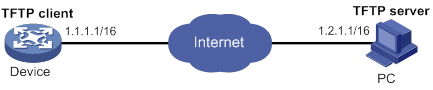
Usage procedure
# Identify which files are stored and how much space is available in the file system.
<boot> dir
Directory of flash:
0 drw- 5954 Apr 26 2016 21:06:29 logfile
1 -rw- 1842 Apr 27 2016 04:37:17 boot.bin
2 -rw- 1518 Apr 26 2016 12:05:38 startup.cfg
3 -rw- 2045 May 04 2016 15:50:01 backcfg.cfg
524288 KB total (513248 KB free)
The output shows that the boot image boot.bin is present but the matching system image system.bin is not. The available space is 513248 KB, enough for saving the system image system.bin.
# Identify the version information of the boot image.
<boot> display version
H3C Comware Software, Version 7.1.064, Alpha 0408P05
Copyright (c) 2004-2017 New H3C Technologies Co., Ltd. All rights reserved.
H3C MSR3610 uptime is 0 weeks, 0 days, 3 hours, 50 minutes
Last reboot reason : Power on
Boot image: flash:/msr36x1-cmw710-boot-a0408p05.bin
Boot image version: 7.1.064P19, Alpha 0408P05
Compiled Jun 20 2016 16:00:00
System image: flash:/msr36x1-cmw710-system-a0408p05.bin
System image version: 7.1.064, Alpha 0408P05
Compiled Jun 20 2016 16:00:00
Feature image(s) list:
flash:/msr36x1-cmw710-security-a0408p05.bin, version: 7.1.064
Compiled Jun 20 2016 16:00:00
flash:/msr36x1-cmw710-voice-a0408p05.bin, version: 7.1.064
Compiled Jun 20 2016 16:00:00
flash:/msr36x1-cmw710-data-a0408p05.bin, version: 7.1.064
Compiled Jun 20 2016 16:00:00
Slot 1: H3C MSR3610-X1-DP uptime is 0 weeks, 0 days, 3 hours, 50 minutes
Last reboot reason : Power on
CPU ID: 0x11
2G bytes DDR3 SDRAM Memory
8M bytes Flash Memory
PCB Version: 2.0
CPLD Version:129.0
Basic BootWare Version: 1.01
Extended BootWare Version: 1.01
# Configure an IP address and a gateway for the management Ethernet interface.
<boot> system-view
[boot] interface m-eth0
[boot-m-eth0] ip address 1.1.1.1 16
[boot-m-eth0] ip gateway 1.1.1.2
# Verify that the device and the TFTP server can reach each other.
<boot> ping 1.2.1.1
PING 1.2.1.1 (1.2.1.1): 56 data bytes
56 bytes from 1.2.1.1: seq=0 ttl=128 time=2.243 ms
56 bytes from 1.2.1.1: seq=1 ttl=128 time=0.717 ms
56 bytes from 1.2.1.1: seq=2 ttl=128 time=0.891 ms
56 bytes from 1.2.1.1: seq=3 ttl=128 time=0.745 ms
56 bytes from 1.2.1.1: seq=4 ttl=128 time=0.911 ms
--- 1.2.1.1 ping statistics ---
5 packets transmitted, 5 packets received, 0% packet loss
round-trip min/avg/max = 0.717/1.101/2.243 ms
# Download the file system.bin from the TFTP server.
<boot> tftp 1.2.1.1 get system.bin flash:/system.bin
# Verify that the system image is compatible with the boot image.
<boot> display install package cfa0:/system.bin
cfa0:/system.bin
[Package]
Vendor: H3C
Product: MSR36
Service name: boot
Platform version: 7.1.064P19
Product version: Alpha 0408P05
Supported board: MSR36-10,MSR36-20,MSR3620-DP,MSR36-40,MSR36-60
# Load the system image to start the Comware system.
<boot> install load flash:/system.bin
flash:/system.bin
[Package]
Vendor: H3C
Product: MSR36
Service name: system
Platform version: 7.1.064
Product version: Alpha 0408P05
Supported board: MSR36-10,MSR36-20,MSR3620-DP,MSR36-40,MSR36-60
After you press Enter, the following information appears:
<System>
<System>%May 23 18:29:59:777 2016 MSR36 SHELL/5/SHELL_LOGIN: TTY logged in from
aux0.
Using automatic configuration
Overview
With the automatic configuration feature, the device can automatically obtain a set of configuration settings at startup. This feature simplifies network configuration and maintenance.
Automatic configuration can be implemented by using a set of servers, a USB disk, or the short message service (SMS).
· Server-based automatic configuration—Requires a DHCP server and a file server (HTTP or TFTP server). A DNS server might also be required.
· USB-based automatic configuration—Requires a USB disk with the configuration file.
· SMS-based automatic configuration—Requires an IMC server, a 3G or 4G network, a cell phone or an SMS gateway, and 3G or 4G modem modules with 3G or 4G SIM cards.
Server-based automatic configuration applies to scenarios that have the following characteristics:
· A number of devices need to be configured.
· The devices to be configured are widely distributed.
· The configuration workload on individual devices is heavy.
USB-based automatic configuration applies to scenarios that have the following characteristics:
· Only a few devices require automatic configuration or configuration update.
· The devices to be configured reside near to each other.
· No host can be used as a file server.
SMS-based automatic configuration applies to scenarios that have the following characteristics:
· Devices to be configured are geographically distributed.
· There are 3G or 4G networks available for wireless communication.
The device prefers USB-based automatic configuration. As a best practice, use SMS-based automatic configuration only when you do not have any other choices. SMS-based automatic configuration has the following disadvantages:
· High cost.
· Low reliability. Short messages depend on 3G or 4G networks. Wireless signals might be unstable.
Feature and hardware compatibility
The following matrix shows the feature and hardware compatibility:
|
Hardware |
Automatic configuration compatibility |
|
MSR810-LMS/810-LUS |
No |
|
MSR810/810-W/810-W-DB/810-LM/810-W-LM/810-10-PoE/810-LM-HK/810-W-LM-HK |
Yes |
|
MSR2600-6-X1/2600-10-X1 |
Yes |
|
MSR 2630 |
Yes |
|
MSR3600-28/3600-51 |
Yes |
|
MSR3600-28-SI/3600-51-SI |
No |
|
MSR3610-X1/3610-X1-DP/3610-X1-DC/3610-X1-DP-DC |
Yes |
|
MSR 3610/3620/3620-DP/3640/3660 |
Yes |
|
MSR5620/5660/5680 |
Yes |
Using server-based automatic configuration
As shown in Figure 45, server-based automatic configuration requires the following servers:
· DHCP server.
· File server (TFTP or HTTP server).
· (Optional.) DNS server.
Figure 45 Server-based automatic configuration network diagram
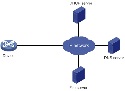
Server-based automatic configuration task list
|
Tasks at a glance |
|
(Required.) Configuring the file server |
|
(Required.) Preparing the files for automatic configuration |
|
(Required.) Configuring the DHCP server |
|
(Optional.) Configuring the DNS server |
|
(Optional.) Configuring the gateway |
|
(Required.) Preparing the interface used for automatic configuration |
|
(Required.) Starting and completing automatic configuration |
Configuring the file server
For devices to obtain configuration information from a TFTP server, start TFTP service on the file server.
For devices to obtain configuration information from an HTTP server, start HTTP service on the file server.
Preparing the files for automatic configuration
The device can use a script file or configuration file for automatic configuration.
· For devices to use configuration files for automatic configuration, you must create and save the configuration files to the file server as described in "Configuration files." If you do not configure the DHCP server to assign configuration file names, you must also create a host name file on the TFTP server.
· For devices to use script files for automatic configuration, you must create and save the script files to the file server as described in "Script files."
Host name file
The host name file contains host name-IP address mappings and must be named network.cfg.
All mapping entries in the host name file must use the ip host host-name ip-address format. Each mapping entry must reside on a separate line. For example:
ip host host2 101.101.101.102
ip host client1 101.101.101.103
ip host client2 101.101.101.104
Configuration files
To prepare configuration files:
· For devices that require different configurations, perform the following tasks:
? Determine the name for each device's configuration file.
The configuration file names must use the extension .cfg. For simple file name identification, use configuration file names that do not contain spaces.
? Use the file names to save the configuration files for the devices to the file server.
· For devices that share all or some configurations, save the common configurations to a .cfg file on the file server.
· If a TFTP file server is used, you can save a default configuration file named device.cfg on the server. This file contains only common configurations that devices use to start up. This file is assigned to a device only when the device does not have other configuration files to use.
During the automatic configuration process, a device first tries to obtain a configuration file dedicated for it. If no dedicated configuration file is found, the device tries to obtain the common configuration file. If no common configuration file is found when a TFTP file server is used, the device obtains and uses the default configuration file.
Script files
Script files can be used for automatic software upgrade and automatic configuration. The device supports Python scripts (.py files) and Tcl scripts (.tcl files). For more information about Python and Tcl scripts, see "Using Python" and "Using Tcl."
To prepare script files:
· For devices that share all or some configurations, create a script file that contains the common configurations.
· For the other devices, create a separate script file for each of them.
Configuring the DHCP server
The DHCP server assigns the following items to devices that need to be automatically configured:
· IP addresses.
· Paths of the configuration files or scripts.
Configuration guidelines
When you configure the DHCP server, follow these guidelines:
· For devices for which you have prepared different configuration files, perform the following tasks for each of the devices on the DHCP server:
? Create a DHCP address pool.
? Configure a static address binding.
? Specify a configuration file or script file.
Because an address pool can use only one configuration file, you can specify only one static address binding for an address pool.
· For devices for which you have prepared the same configuration file, use either of the following methods:
? Method 1:
- Create a DHCP address pool for the devices.
- Configure a static address binding for each of the devices in the address pool.
- Specify the configuration file for the devices.
? Method 2:
- Create a DHCP address pool for the devices.
- Specify the subnet for dynamic allocation.
- Specify the TFTP server.
- Specify the configuration file for the devices.
· If all devices on a subnet share the same configuration file or script file, perform the following tasks on the DHCP server:
? Configure dynamic address allocation.
? Specify the configuration file or script file for the devices.
The configuration file can contain only the common settings for the devices. You can provide a method for the device administrators to change the configurations after their devices start up.
Configuring the DHCP server when an HTTP file server is used
|
Step |
Command |
Remarks |
|
1. Enter system view. |
system-view |
N/A |
|
2. Enable DHCP. |
dhcp enable |
By default, DHCP is disabled. |
|
3. Create a DHCP address pool and enter its view. |
dhcp server ip-pool pool-name |
By default, no DHCP address pool is created. |
|
4. Configure the address pool. |
·
(Method 1.) Specify the primary subnet for the
address pool: ·
(Method 2.) Configure a static binding: |
Use either or both methods. By default, no primary subnet or static binding is configured. You can add multiple static bindings. One IP address can be bound to only one client. To change the binding for a DHCP client, you must remove the binding and reconfigure a binding. |
|
5. Specify the URL of the configuration file or script file. |
bootfile-name url |
By default, no configuration or script file URL is specified. |
Configuring the DHCP server when a TFTP file server is used
|
Step |
Command |
Remarks |
|
1. Enter system view. |
system-view |
N/A |
|
2. Enable DHCP. |
dhcp enable |
By default, DHCP is disabled. |
|
3. Create a DHCP address pool and enter its view. |
dhcp server ip-pool pool-name |
By default, no DHCP address pool is created. |
|
4. Configure the address pool. |
·
(Method 1.) Specify the primary subnet for the
address pool: ·
(Method 2.) Configure a static binding: |
Use either or both methods. By default, no primary subnet or static binding is configured. You can add multiple static bindings. One IP address can be bound to only one client. To change the binding for a DHCP client, you must remove the binding and reconfigure a binding. |
|
5. Specify a TFTP server. |
·
(Method 1.) Specify the IP address of the TFTP
server: ·
(Method 2.) Specify the name of the TFTP
server: |
Use either or both methods. By default, no TFTP server is specified. If you specify a TFTP server by its name, a DNS server is required on the network. |
|
6. Specify the configuration or script file name. |
bootfile-name bootfile-name |
By default, no configuration or script file name is specified. |
Configuring the DNS server
A DNS server is required in the following situations:
· The TFTP server does not have a host name file. However, devices need to perform the following operations:
? Use their IP addresses to obtain their host names.
? Obtain configuration files named in the host name.cfg format from the TFTP server.
· The DHCP server assigns the TFTP server domain name through the DHCP reply message. Devices must use the domain name to obtain the IP address of the TFTP server.
Configuring the gateway
If the devices to be automatically configured and the servers for automatic configuration reside in different network segments, you must perform the following tasks:
· Deploy a gateway and make sure the devices can communicate with the servers.
· Configure the DHCP relay agent feature on the gateway.
· Configure the UDP helper feature on the gateway.
Preparing the interface used for automatic configuration
The device uses the following steps to select the interface for automatic configuration:
1. Identifies the status of the management Ethernet interface at Layer 2. If the status is up, the device uses the management Ethernet interface.
2. Identifies the status of Layer 2 Ethernet interfaces. If one or more Layer 2 Ethernet interfaces are in up state, the device uses the VLAN interface of the default VLAN.
3. Sorts all Layer 3 Ethernet interfaces in up state first in lexicographical order of interface types and then in ascending order of interface numbers. Uses the interface with the smallest interface number among the interfaces of the first interface type.
4. If no Layer 3 Ethernet interfaces are in up state, the device waits 30 seconds and goes to step 1 to try again.
For fast automatic device configuration, connect only the management Ethernet interface on each device to the network.
Starting and completing automatic configuration
1. Power on the devices to be automatically configured.
If a device does not find a next-start configuration file locally, it starts the automatic configuration process to obtain a configuration file.
? If the device obtains a configuration file and executes the file successfully, the automatic configuration process ends.
? If one attempt fails, the device tries again until the maximum number of attempts is reached. To stop the process, press Ctrl+C or Ctrl+D. The maximum number of attempts depends on the device model.
If the device fails to obtain a configuration file, the device starts up without loading any configuration.
2. Use the save command to save the running configuration.
The device does not save the obtained configuration file locally. If you do not save the running configuration, the device must use the automatic configuration feature again after a reboot.
For more information about the save command, see Fundamentals Command Reference.
Using USB-based automatic configuration
USB-based automatic configuration enables the device to obtain a configuration file from a connected USB disk at startup.
At startup, the device first searches for a .mdb next-startup configuration file.
· If a .mdb next-startup configuration file exists on the default file system, the device performs the following operations:
? Loads the file.
? Copies the configuration file on the USB disk to its default file system and sets it as main next-start configuration file.
? If a .mdb next-startup configuration file uses the same basic file name as the new main next-start configuration file, the device deletes the .mdb file.
? Reboots.
· If no .mdb next-startup configuration files exist on the default file system, the device performs the following operations:
? Copies the configuration file on the USB disk to its default file system and sets it as main next-start configuration file.
? Loads the file.
The device loads settings for some features before entering the automatic configuration process. After completing the automatic configuration process, the device reboots.
After obtaining a configuration file from the USB disk, the device compares the file with its main startup configuration file.
· If the two files have the same settings, the device loads its main startup configuration file.
· If the two files have different settings or the device does not have a main startup configuration file, the device performs the following operations:
a. Loads the obtained configuration file.
If a command in the obtained configuration file fails, the device rolls back all loaded settings and searches for a configuration file on the device.
- If a configuration file is found, the device loads the configuration file.
- If no configuration file is found, the device finishes the automatic configuration process without loading any configurations.
b. Saves the file as the new startup configuration file.
- If the two versions of main startup configuration files have the same name, the original file is renamed by using the name original base name_bak.cfg.
- If another file is using the same name as the new main startup configuration file, the file is overwritten.
For more information about .mdb and .cfg configuration files, see "Managing configuration files."
Preparing the USB disk for automatic configuration
Create and save the configuration files for automatic configuration to the root directory of the USB disk.
A configuration file can use the name Device serial number.cfg or autodeploy.cfg. To use Device serial number.cfg for a configuration file, first use the display device manuinfo command to obtain the device's serial number. For more information about this command, see Fundamentals Command Reference.
USB-based automatic configuration procedure
1. Verify that USB-based automatic configuration is enabled on the device:
a. Use the display startup command to display the names of the startup configuration files.
b. Use the display saved-configuration command to display the startup configuration file for the next startup. For more information about the display startup and display saved-configuration commands, see Fundamentals Command Reference.
c. If the file contains the undo autodeploy udisk enable command, perform the following task to enable USB-based automatic configuration:
|
Step |
Command |
Remarks |
|
1. Enter system view. |
system-view |
N/A |
|
2. Enable USB-based automatic configuration. |
By default, USB-based automatic configuration is enabled. |
2. If the device has two MPUs, remove one MPU.
3. Connect the USB disk to the USB1 interface on the device.
The device does not check the USB disk for automatic configuration after it starts up.
The USB disk will be identified as usba0.
4. Power on the device.
? If the automatic configuration succeeded, the SYS LED flashes green quickly for 5 seconds. Proceed with step 5.
? If the automatic configuration failed, the SYS LED flashes yellow quickly for 10 seconds. Display the log file named Fully qualified configuration file name.log in the USB disk root directory to locate and resolve the problem.
5. If the automatic configuration succeeded, use the display current-configuration command to verify that the configuration file has been loaded correctly. For more information about this command, see Fundamentals Command Reference.
6. Remove the USB disk.
If you do not remove the USB disk, the device might start USB-based automatic configuration at the next reboot.
7. If you removed one MPU in step 1, install the MPU.
The MPU automatically synchronizes the configuration of the active MPU.
Using SMS-based automatic configuration
To initiate the SMS-based automatic configuration process, use either of the following methods to send a short message to the device:
· A cell phone.
· The IMC server. The IMC server sends short messages to devices through an SMS gateway and starts a timeout timer for each sent short message. You can set the timer on the IMC server.
The device sends a confirmation after receiving a short message.
· If the cell phone used to initiate automatic configuration does not receive the confirmation, use the cell phone to send the short message again.
· If the IMC server used to initiate automatic configuration does not receive the confirmation before the timeout timer expires, the SMS gateway automatically retransmits the short message.
After obtaining and loading a configuration file, the device sends the automatic configuration result to the IMC server through the 3G or 4G network. You can log in to the IMC server to view whether the automatic configuration has succeeded.
Configuration guidelines
When you use SMS-based automatic configuration, follow these guidelines:
· A short message might take some time to arrive at the device because of reasons such as wireless signal interference and strength decrease.
· A short message sent by a cell phone must be compliant with the following template:
dpl:
pu:card
ps:card
dn:*99#
an:3gnet
ac:http://60.191.123.87:9090
au:admin
as:admin
Table 15 Short message template fields
|
Field |
Description |
|
(Required.) Deployment short message identification. The device initiates the automatic configuration process only when the short message starts with this identification. |
|
|
(Required when CHAP authentication and PAP authentication are used.) Username for PPP authentication. |
|
|
(Required when only CHAP authentication is used.) Username for PPP authentication. |
|
|
(Required when only PAP authentication is used.) Username for PPP authentication. |
|
|
(Required when PPP authentication is used.) Password for PPP authentication. |
|
|
(Required.) PPP dial number provided by the service provider. For example, the PPP dial number is *99# for both China Mobile and China Unicom, and is #777 for China Telecom. |
|
|
(Required when the service provider is not China Mobile, China Unicom, or China Telecom.) Name of the 3G or 4G access point provided by the service provider. |
|
|
(Required.) URL of the IMC ACS. |
|
|
(Required.) Username for IMC login. |
|
|
(Required.) Password for IMC login. |
Preparing for SMS-based automatic configuration
1. Prepare an IMC server and an SMS gateway (or cell phone). Make sure the IMC server and the SMS gateway (or cell phone) can reach each other.
2. Verify that the device to be configured has a 3G or 4G modem module. Make sure the modem module has a 3G or 4G SIM card installed and the SIM card account balance is sufficient.
If the modem uses a USB interface, you can install the modem to a PC to test whether you can use the modem to connect to the 3G or 4G network correctly.
3. On the device to be automatically configured, perform the following tasks:
? Configure a loopback interface and assign an IP address to the interface.
? Enable SMS-based automatic configuration.
To enable SMS-based automatic configuration:
|
Step |
Command |
Remarks |
|
1. Enter system view. |
system-view |
N/A |
|
2. Enable SMS-based automatic configuration. |
autodeploy sms enable |
By default, SMS-based automatic configuration is enabled. |
4. Configure the IMC server:
a. Add the device to be configured. Configure parameters for the device, including the device name, SIM number, and SIM vendor. Use the IP address for the previously configured loopback interface as the management address.
b. Create the configuration file used for automatic configuration, and configure the binding between the file and the device.
c. Configure IMC to assign the configuration file to the device.
d. To use an SMS gateway to send short messages, perform the following tasks:
- Configure the IMC server to use an SMS gateway to initiate SMS-based device configuration.
- Select the SMS gateway, set the maximum number of retransmission attempts, and set the timeout time.
- Configure the IMC server to create the short message. Enable the short message sending function on the SMS gateway.
5. To use a cell phone to send short messages, create a short message on the cell phone.
Starting and completing SMS-based automatic configuration
1. Use the IMC server or cell phone to send the preconfigured short message to the device.
2. On the device, use the display current-configuration command to view whether the device has loaded the configuration file.
If you used the IMC server to send the short message, you can also log in to the IMC server to view whether the automatic configuration has succeeded.
Server-based automatic configuration examples
Automatic configuration using TFTP server
Network requirements
As shown in Figure 46, Router B does not have a configuration file.
Configure the servers so Router B can obtain a configuration file to complete the following configuration tasks:
· Enable the administrator to Telnet to Router B to manage Router B.
· Require the administrator to enter the correct username and password at login.
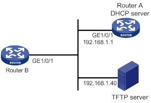
Configuration procedure
1. Configure the DHCP server:
# Enable DHCP.
<RouterA> system-view
[RouterA] dhcp enable
# Configure the address pool 1 to assign IP addresses on the subnet 192.168.1.0/24 to clients. Specify the TFTP server and configuration file name for the clients.
[RouterA] dhcp server ip-pool 1
[RouterA-dhcp-pool-1] network 192.168.1.0 24
[RouterA-dhcp-pool-1] tftp-server ip-address 192.168.1.40
[RouterA-dhcp-pool-1] bootfile-name device.cfg
[RouterA-dhcp-pool-market] quit
2. Configure the TFTP server:
# On the TFTP server, create the configuration file device.cfg.
#
telnet server enable
#
local-user user
password simple abcabc
service-type telnet
authorization-attribute user-role network-operator
quit
#
user-interface vty 0 4
authentication-mode scheme
user-role network-admin
quit
#
interface gigabitethernet 1/0/1
port link-mode route
ip address dhcp-alloc
return
# Start TFTP service software. (Details not shown.)
Verifying the configuration
1. Power on Router B.
2. After Router B starts up, display assigned IP addresses on Router A.
<RouterA> display dhcp server ip-in-use
IP address Client identifier/ Lease expiration Type
Hardware address
192.168.1.2 0030-3030-632e-3239- May 12 17:41:15 2016 Auto(C)
3035-2e36-3736-622d-
4574-6830-2f30-2f32
3. Telnet to 192.168.1.2 from Router A.
<RouterA> telnet 192.168.1.2
4. Enter the username user and password abcabc as prompted. (Details not shown.)
You are logged in to Router B.
Automatic configuration using HTTP server and Tcl script
Network requirements
As shown in Figure 47, Router B does not have a configuration file.
Configure the servers so Router B can obtain a Tcl script to complete the following configuration tasks:
· Enable the administrator to Telnet to Router B to manage Router B.
· Require the administrator to enter the correct username and password at login.

Configuration procedure
1. Configure the DHCP server:
# Enable DHCP.
<RouterA> system-view
[RouterA] dhcp enable
# Configure the address pool 1 to assign IP addresses on the subnet 192.168.1.0/24 to clients.
[RouterA] dhcp server ip-pool 1
[RouterA-dhcp-pool-1] network 192.168.1.0 24
# Specify the URL of the script file for the clients.
[RouterA-dhcp-pool-1] bootfile-name http://192.168.1.40/device.tcl
2. Configure the HTTP server:
# Create the configuration file device.tcl on the HTTP server.
system-view
telnet server enable
local-user user
password simple abcabc
service-type telnet
quit
user-interface vty 0 4
authentication-mode scheme
user-role network-admin
quit
interface gigabitethernet 1/0/1
port link-mode route
ip address dhcp-alloc
return
# Start HTTP service software and enable HTTP service. (Details not shown.)
Verifying the configuration
1. Power on Router B.
2. After Router B starts up, display assigned IP addresses on Router A.
<RouterA> display dhcp server ip-in-use
IP address Client identifier/ Lease expiration Type
Hardware address
192.168.1.2 0030-3030-632e-3239- May 12 17:41:15 2016 Auto(C)
3035-2e36-3736-622d-
4574-6830-2f30-2f32
3. Telnet to 192.168.1.2 from Router A.
<RouterA> telnet 192.168.1.2
4. Enter the username user and password abcabc as prompted. (Details not shown.)
You are logged in to Router B.
Automatic configuration using HTTP server and Python script
|
|
NOTE: For support information about this example, see " Using Python." |
Network requirements
As shown in Figure 48, Router B does not have a configuration file.
Configure the servers so Router B can obtain a Python script to complete the following configuration tasks:
· Enable the administrator to Telnet to Router B to manage Router B.
· Require the administrator to enter the correct username and password at login.
Configuration procedure
1. Configure the DHCP server:
# Enable DHCP.
<RouterA> system-view
[RouterA] dhcp enable
# Configure address pool 1 to assign IP addresses on the subnet 192.168.1.0/24 to clients.
[RouterA] dhcp server ip-pool 1
[RouterA-dhcp-pool-1] network 192.168.1.0 24
# Specify the URL of the script file for the clients.
[RouterA-dhcp-pool-1] bootfile-name http://192.168.1.40/device.py
2. Configure the HTTP server:
# Create the configuration file device.py on the HTTP server.
#!usr/bin/python
import comware
comware.CLI(‘system-view ;telnet server enable ;local-user user ;password simple abcabc ;service-type telnet ;quit ;user-interface vty 0 4 ;authentication-mode scheme ;user-role network-admin ;quit ;interface gigabitethernet 1/0/1 ;port link-mode route ;ip address dhcp-alloc ;return ’)
# Start HTTP service software and enable HTTP service. (Details not shown.)
Verifying the configuration
1. Power on Router B.
2. After Router B starts up, display assigned IP addresses on Router A.
<RouterA> display dhcp server ip-in-use
IP address Client identifier/ Lease expiration Type
Hardware address
192.168.1.2 0030-3030-632e-3239- May 12 17:41:15 2016 Auto(C)
3035-2e36-3736-622d-
4574-6830-2f30-2f32
3. Telnet to 192.168.1.2 from Router A.
<RouterA> telnet 192.168.1.2
4. Enter the username user and password abcabc as prompted. (Details not shown.)
You are logged in to Router B.
Automatic IRF setup
Network requirements
As shown in Figure 49, Router A and Router B do not have a configuration file.
Configure the servers so the routers can obtain a Python script to complete their respective configurations and form an IRF fabric.
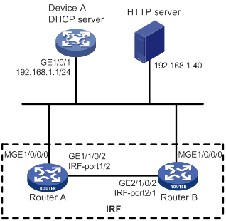
Configuration procedure
1. Assign IP addresses to the interfaces. Make sure the devices can reach each other. (Details not shown.)
2. Configure the following files on the HTTP server:
|
File |
Content |
Remarks |
|
.cfg configuration file |
Commands required for IRF setup. |
You can create a configuration file by copying and modifying the configuration file of an existing IRF fabric. |
|
sn.txt |
Serial numbers of the member routers. |
Each SN uniquely identifies a router. These SNs will be used for assigning a unique IRF member ID to each member router. |
|
(Optional.) .ipe or .bin software image file |
Software images. |
If the member routers are running different software versions, you must prepare the software image file used for software upgrade. |
|
.py Python script file |
Python commands that complete the following tasks: a (Optional.) Verify that the flash memory has sufficient space for the files to be downloaded. b Download the configuration file and sn.txt. c (Optional.) Download the software image file and specify it as the main startup image file. d Resolve sn.txt and assign a unique IRF member ID to each SN. e Specify the configuration file as the main next-startup configuration file. f Reboot the member routers. |
For more information about Python script configuration, see "Using Python." |
3. Configure Device A as the DHCP server:
# Enable DHCP.
<DeviceA> system-view
[DeviceA] dhcp enable
# Configure address pool 1 to assign IP addresses on the subnet 192.168.1.0/24 to clients.
[DeviceA] dhcp server ip-pool 1
[DeviceA-dhcp-pool-1] network 192.168.1.0 24
# Specify the URL of the script file for the clients.
[DeviceA-dhcp-pool-1] bootfile-name http://192.168.1.40/device.py
[DeviceA-dhcp-pool-1] quit
# Enable the DHCP server on GigabitEthernet 1/0/1.
[DeviceA] interface gigabitethernet 1/0/1
[DeviceA-GigabitEthernet1/0/1] dhcp select server
[DeviceA-GigabitEthernet1/0/1] quit
4. Power on Router A and Router B.
Router A and Router B will obtain the Python script file from the DHCP server and execute the script. After completing the IRF configuration, Router A and Router B reboot.
5. After Router A and Router B start up again, use a cable to connect Router A and Router B through their IRF physical ports.
Router A and Router B will elect a master member. The subordinate member will reboot to join the IRF fabric.
Verifying the configuration
# On Router A, display IRF member devices. You can also use the display irf command on Router B to display IRF member devices.
<RouterA> display irf
MemberID Slot Role Priority CPU-Mac Description
1 1 Standby 1 00e0-fc0f-8c02 ---
*+2 1 Master 30 00e0-fc0f-8c14 ---
--------------------------------------------------
* indicates the device is the master.
+ indicates the device through which the user logs in.
The Bridge MAC of the IRF is: 000c-1000-1111
Auto upgrade : yes
Mac persistent : always
Domain ID : 0
Auto merge : yes
The output shows that the routers have formed an IRF fabric.
Configuring security zones
Overview
You can configure security zones to implement security zone-based security management.
Basic concepts
The security zone feature includes the following basic concepts:
· Security zone—A security zone is a collection of interfaces that have the same security requirements.
· System-defined security zones—The device provides the following system-defined security zones: Local, Trust, DMZ, Management, and Untrust. These security zones are created automatically by the system when one of following events occurs:
? The first command for creating a security zone is executed.
? The first command for creating a zone pair is executed.
System-defined security zones cannot be deleted.
· DMZ—A demilitarized zone is a network that is separate from the internal network and the external network both logically and physically. Typically, a DMZ contains devices for the public to access, such as the Web servers and FTP servers.
Security zone-based security management
For example, your enterprise has four network segments for the R&D department and two network segments for the servers. You can perform the following tasks to control traffic between the security zones:
· Create two security zones: Zone_RND and Zone_DMZ.
· Assign the four firewall interfaces that are connected to the R&D department to Zone_RND.
· Assign the two firewall interfaces that are connected to the servers to Zone_DMZ.
· Deploy security policies between the two security zones, including ACLs, ASPF policies, and object policies.
If the network topology changes, you only need to change interface assignments. You do not need to modify the security policies. For more information about packet filtering policies, see ACL and QoS Configuration Guide. For more information about ASPF and object policies, see Security Configuration Guide.
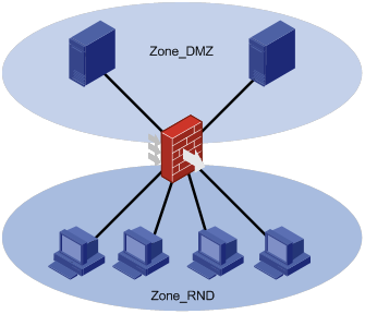
The following table describes how the device handles packets when security zone-based security management is configured:
|
Packets |
Action |
|
Packets between an interface that is in a security zone and an interface that is not in any security zone |
Discard. |
|
Packets between two interfaces that are in the same security zone |
Discard by default. |
|
Packets between two interfaces that belong to different security zones |
Forward or discard, depending on the matching object policy. If the object policy does not exist or does not take effect, the packets are discarded. For more information, see "Creating a zone pair." |
|
Packets between two interfaces that are not in any security zone |
Forward. |
|
Packets originated from or destined for the device itself |
Forward or discard, depending on the matching object policy. By default, these packets are forwarded. |
Application scenarios
As a best practice, use security zone-based security management when the firewall is connected to multiple network segments or the network topology might change.
The traditional security management technology is based on interfaces. To filter packets, you must apply security policies on the inbound and outbound interfaces of a firewall. When the firewall is connected to multiple network segments, deploying security policies is time consuming and complicated. If the network topology changes, you might have to reconfigure security policies.
Feature and hardware compatibility
The following matrix shows the feature and hardware compatibility:
|
Hardware |
Security zone compatibility |
|
MSR810/810-W/810-W-DB/810-LM/810-W-LM/810-10-PoE/810-LM-HK/810-W-LM-HK/810-LMS/810-LUS |
Yes except on MSR810-LMS/810-LUS |
|
MSR2600-10-X1 |
Yes |
|
MSR 2630 |
Yes |
|
MSR3600-28/3600-51 |
Yes |
|
MSR3600-28-SI/3600-51-SI |
Yes |
|
MSR3610-X1/3610-X1-DP/3610-X1-DC/3610-X1-DP-DC |
Yes |
|
MSR 3610/3620/3620-DP/3640/3660 |
Yes |
|
MSR5620/5660/5680 |
Yes |
|
Hardware |
Security zone compatibility |
|
MSR810-LM-GL |
Yes |
|
MSR810-W-LM-GL |
Yes |
|
MSR830-6EI-GL |
Yes |
|
MSR830-10EI-GL |
Yes |
|
MSR830-6HI-GL |
Yes |
|
MSR830-10HI-GL |
Yes |
|
MSR2600-6-X1-GL |
Yes |
|
MSR3600-28-SI-GL |
Yes |
Restrictions and guidelines
Security zone settings cannot be rolled back.
Security zone configuration task list
|
(Required.) Creating a security zone |
|
(Required.) Adding members to a security zone |
|
(Optional.) Creating a zone pair |
|
(Optional.) Specifying the default action for packets between interfaces in the same security zone |
Configuring a security zone
Creating a security zone
|
Command |
Remarks |
|
|
1. Enter system view. |
N/A |
|
|
2. Create a security zone and enter security zone view. |
security-zone name zone-name |
By default, no security zone exists on the device. |
Adding members to a security zone
A security zone can include member types listed in Table 16.
Table 16 Security zone members and objects that the members identify
|
Security zone member |
Objects that each member identifies |
|
Layer 3 interface: · Layer 3 Ethernet interface · Layer 3 logical interface, such as a Layer 3 subinterface |
All packets received or sent on the interface |
|
Layer 2 interface-VLAN combination |
All packets received or sent on the interface that carry the specified VLAN tag |
To add members to a security zone:
|
Command |
Remarks |
|
|
1. Enter system view. |
N/A |
|
|
2. Enter security zone view. |
N/A |
|
|
3. Add members to the security zone. |
·
Add a Layer 3 Ethernet interface: ·
Add Layer 2 interface-VLAN combinations: |
By default, a security zone does not have members. You can perform this step multiple times to add multiple members. |
Creating a zone pair
A zone pair has a source security zone and a destination security zone. The device examines received first data packets and uses zone pairs to identify data flows.
You can use the zone-pair security source any destination any command to define the any-to-any zone pair. This zone pair matches all packets from one security zone to another security zone.
After you apply security policies to zone pairs, the device processes data flows based on security policies.
· If a packet matches a zone pair between specific security zones, the device processes the packet by using the security policies applied to the zone pair.
· If a packet does not match any zone pair between specific security zones, the device identifies whether the packet is between the Management and Local zones.
? If the packet is between the Management and Local zones, the device discards the packet.
? If the packet is not between the Management and Local zones, the device searches for the any-to-any zone pair.
- If the zone pair exists, the device processes the packet by using the security policies applied to the zone pair.
- If the zone pair does not exist, the device discards the packet.
If both an object policy and a packet filtering policy are applied to a zone pair, the object policy takes effect.
To create a zone pair:
|
Command |
Remarks |
|
|
1. Enter system view. |
N/A |
|
|
2. Create a zone pair and enter zone pair view. |
zone-pair security source { source-zone-name | any } destination { destination-zone-name | any } |
By default, no zone pair exists. |
Specifying the default action for packets between interfaces in the same security zone
By default, packets exchanged between interfaces in the same security zone are dropped if no zone pair is configured from a security zone to the security zone itself. You can use this feature to change the processing policy for the packets.
To specify the default action for packets exchanged between interfaces in the same security zone:
|
Step |
Command |
Remarks |
|
1. Enter system view. |
system-view |
N/A |
|
2. Specify the default action for packets exchanged between interfaces in the same security zone. |
·
Set the default action to permit: ·
Set the default action to deny: |
By default, the default action is deny for packets exchanged between interfaces in the same security zone. |
Displaying security zones
Execute display commands in any view.
|
Command |
|
|
Display security zone information. |
|
|
Display zone pair information. |
Security zone configuration example
Network requirements
As shown in Figure 51, a firewall (Device) connects the corporate network to the Internet. The corporate network needs to provide Web services and FTP services for external users.
To ensure corporate network security, configure the firewall as follows:
· Assign the interfaces used to connect the internal network, the servers, and the Internet to security zones Trust, DMZ, and Untrust, respectively.
· Configure zone pairs and apply object policies to control access as follows:
? Allow internal users to access the Web and FTP servers and the Internet.
? Allow external users to access the Web and FTP servers.
? Allow the Web server and FTP server to access the Internet.
? Forbid external users and the Web server and FTP server to access the internal network.
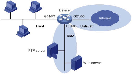
Configuration procedure
# Add interface GigabitEthernet 1/0/1 to security zone Trust.
[Device] security-zone name trust
[Device-security-zone-Trust] import interface gigabitethernet 1/0/1
[Device-security-zone-Trust] quit
# Add interface GigabitEthernet 1/0/2 to security zone DMZ.
[Device] security-zone name dmz
[Device-security-zone-DMZ] import interface gigabitethernet 1/0/2
[Device-security-zone-DMZ] quit
# Add interface GigabitEthernet 1/0/3 to security zone Untrust.
[Device] security-zone name untrust
[Device-security-zone-Untrust] import interface gigabitethernet 1/0/3
[Device-security-zone-Untrust] quit
# Configure ACL 3500 to permit IP traffic.
[Device] acl advanced 3500
[Device-acl-ipv4-3500] rule permit ip
[Device-acl-ipv4-3500] quit
# Configure ASPF policy 1 to detect FTP traffic. To detect other types of traffic, use the detect command to add the protocols.
[Device] aspf policy 1
[Device-aspf-policy-1] detect ftp
[Device-aspf-policy-1] quit
# Create a zone pair with the source security zone Trust and destination security zone Untrust.
[Device] zone-pair security source trust destination untrust
# Apply ASPF policy 1 and ACL 3500 to the zone pair.
[Device-zone-pair-security-Trust-Untrust] aspf apply policy 1
[Device-zone-pair-security-Trust-Untrust] packet-filter 3500
[Device-zone-pair-security-Trust-Untrust] quit
# Create a zone pair with the source security zone Trust and destination security zone DMZ.
[Device] zone-pair security source trust destination dmz
# Apply ASPF policy 1 and ACL 3500 to the zone pair.
[Device-zone-pair-security-Trust-DMZ] aspf apply policy 1
[Device-zone-pair-security-Trust-DMZ] packet-filter 3500
[Device-zone-pair-security-Trust-DMZ] quit
Verifying the configuration
# Verify that internal hosts can access resources on the Internet and the FTP resources in the DMZ zone. (Details not shown.)
# Verify that access requests initiated from the Internet or the DMZ zone are denied. (Details not shown.)
Managing the device
Command and hardware compatibility
Commands and descriptions for centralized devices apply to the following routers:
· MSR810/810-W/810-W-DB/810-LM/810-W-LM/810-10-PoE/810-LM-HK/810-W-LM-HK/810-LMS/810-LUS.
· MSR2600-6-X1/2600-10-X1.
· MSR 2630.
· MSR3600-28/3600-51
· MSR3600-28-SI/3600-51-SI
· MSR3610-X1/3610-X1-DP/3610-X1-DC/3610-X1-DP-DC.
· MSR 3610/3620/3620-DP/3640/3660.
· MSR810-LM-GL/810-W-LM-GL/830-6EI-GL/830-10EI-GL/830-6HI-GL/830-10HI-GL/2600-6-X1-GL/3600-28-SI-GL.
Commands and descriptions for distributed devices apply to the following routers:
· MSR5620.
· MSR 5660.
· MSR 5680.
This chapter describes how to configure basic device parameters and manage the device.
You can perform the configuration tasks in this chapter in any order.
Device management task list
|
Tasks at a glance |
|
(Required.) Configuring the device name |
|
(Required.) Configuring the system time |
|
(Optional.) Enabling displaying the copyright statement |
|
(Optional.) Configuring banners |
|
(Optional.) Rebooting the device |
|
(Optional.) Scheduling a task |
|
(Optional.) Disabling password recovery capability |
|
(Required.) Managing power supply |
|
(Optional.) Setting the port status detection timer |
|
(Optional.) Monitoring CPU usage |
|
(Required.) Setting memory alarm thresholds |
|
(Optional.) Disabling all USB interfaces |
|
(Required.) Setting the operating mode for an interface card |
|
(Required.) Verifying and diagnosing transceiver modules |
|
(Optional.) Restoring the factory-default configuration |
|
(Optional.) Unmounting HMIM modules |
|
(Optional.) Updating the modem firmware through FoTA |
Configuring the device name
A device name (also called hostname) identifies a device in a network and is used in CLI view prompts. For example, if the device name is Sysname, the user view prompt is <Sysname>.
|
Step |
Command |
Remarks |
|
1. Enter system view. |
system-view |
N/A |
|
2. Configure the device name. |
sysname sysname |
The default device name is H3C. |
Configuring the system time
Correct system time is essential to network management and communication. Configure the system time correctly before you run the device on the network.
The device can use the locally set system time, or obtain the UTC time from an NTP source and calculate the system time.
· When using the locally set system time, the device uses the clock signals generated by its built-in crystal oscillator to maintain the system time.
· After obtaining the UTC time from an NTP source, the device uses the UTC time, time zone, and daylight saving time to calculate the system time. Then, the device periodically synchronizes its UTC time and recalculates the system time. For more information about NTP, see Network Management and Monitoring Configuration Guide.
· If you configure the clock protocol controller cellular cellular-number command, the device uses the specified interface and the connected 3G or 4G modem to obtain the network time. If the interface is removed or not activated, the device uses the NTP protocol to obtain the UTC time. After the interface is available, the device uses the 3G or 4G modem to obtain the network time again. For more information about 3G and 4G modem management, see Layer 2—WAN Access Configuration Guide.
The system time calculated by using the UTC time from an NTP time source is more precise.
To configure the system time:
|
Step |
Command |
Remarks |
|
1. Enter system view. |
system-view |
N/A |
|
2. Specify the system time source. |
clock protocol { none | controller cellular cellular-number | ntp } |
By default, the device uses the NTP time source. If you execute this command multiple times, the most recent configuration takes effect. |
|
3. (Optional.) Set the local system time. |
a
Return to user view: b
Specify the local system time: c
Enter system view again: |
Required when the clock protocol none command is configured. |
|
4. Set the time zone. |
clock timezone zone-name { add | minus } zone-offset |
By default, the time zone is not set. This setting must be consistent with the time zone of the place where the device resides. After you set the time zone, the device recalculates the system time. To view the system time, use the display clock command. |
|
5. Set the daylight saving time. |
clock summer-time name start-time start-date end-time end-date add-time |
By default, the daylight saving time is not set. The settings must be consistent with the daylight saving time parameters of the place where the device resides. After you set the daylight saving time, the device recalculates the system time. To view the system time, use the display clock command. |
Enabling displaying the copyright statement
This feature enables the device to display the copyright statement in the following situations:
· When a Telnet or SSH user logs in.
· When a console or AUX user quits user view. This is because the device automatically tries to restart the user session.
The following is a sample copyright statement:
******************************************************************************
* Copyright (c) 2004-2017 New H3C Technologies Co., Ltd. All rights reserved.*
* Without the owner's prior written consent, *
* no decompiling or reverse-engineering shall be allowed. *
******************************************************************************
To enable displaying the copyright statement:
|
Step |
Command |
Remarks |
|
1. Enter system view. |
system-view |
N/A |
|
2. Enable displaying the copyright statement. |
copyright-info enable |
By default, this function is enabled. |
Configuring banners
Banners are messages that the system displays when a user logs in.
Banner types
The system supports the following banners:
· Legal banner—Appears after the copyright or license statement. To continue login, the user must enter Y or press Enter. To quit the process, the user must enter N. Y and N are case insensitive.
· Message of the Day (MOTD) banner—Appears after the legal banner and before the login banner.
· Login banner—Appears only when password or scheme authentication is configured.
· Shell banner—Appears before a user accesses user view.
The system displays the banners in the following order: legal banner, MOTD banner, login banner, and shell banner.
Banner input methods
You can configure a banner by using one of the following methods:
· Input the entire command line in a single line.
The entire command line, including the command keywords, the banner, and the delimiters, can have up to 511 characters. The delimiters for the banner can be any printable character but must be the same. You cannot press Enter before you input the end delimiter.
For example, you can configure the shell banner "Have a nice day." as follows:
<System> system-view
[System] header shell %Have a nice day.%
· Input the command line in multiple lines.
The entire command line, including the command keywords, the banner, and the delimiters, can have up to 2002 characters. The banner can contain carriage returns. A carriage return is counted as two characters.
To input a banner configuration command line in multiple lines, use one of the following methods:
? Press Enter after the final command keyword, type the banner, and end the final line with the delimiter character %.
For example, you can configure the banner "Have a nice day." as follows:
<System> system-view
[System] header shell
Please input banner content, and quit with the character '%'.
Have a nice day.%
? After you type the final command keyword, type any printable character as the start delimiter for the banner and press Enter. Then, type the banner and end the final line with the same delimiter.
For example, you can configure the banner "Have a nice day." as follows:
<System> system-view
[System] header shell A
Please input banner content, and quit with the character 'A'.
Have a nice day.A
? After you type the final command keyword, type the start delimiter and part of the banner. Make sure the final character of the final string is different from the start delimiter. Then, press Enter, type the rest of the banner, and end the final line with the same delimiter.
For example, you can configure the banner "Have a nice day." as follows:
<System> system-view
[System] header shell AHave a nice day.
Please input banner content, and quit with the character 'A'.
A
Configuration procedure
To configure banners:
|
Step |
Command |
Remarks |
|
1. Enter system view. |
system-view |
N/A |
|
2. Configure the legal banner. |
header legal text |
By default, no legal banner is configured. |
|
3. Configure the MOTD banner. |
header motd text |
By default, no MOTD banner is configured. |
|
4. Configure the login banner. |
header login text |
By default, no login banner is configured. |
|
5. Configure the shell banner. |
header shell text |
By default, no shell banner is configured. |
Rebooting the device
|
|
CAUTION: · A device reboot might interrupt network services. · To avoid configuration loss, use the save command to save the running configuration before a reboot. For more information about the save command, see Fundamentals Command Reference. · Before a reboot, use the display startup and display boot-loader commands to verify that the startup configuration file and startup software images are correctly specified. If a startup configuration file or software image problem exists, the device cannot start up correctly. For more information about the two display commands, see Fundamentals Command Reference. |
The following device reboot methods are available:
· Schedule a reboot at the CLI, so the device automatically reboots at the specified time or after the specified period of time.
· Immediately reboot the device at the CLI.
During the reboot process, the device performs the following operations:
a. Resets all of its chips.
b. Uses the Boot ROM to verify the startup software package, decompress the package, and load the images.
c. Initializes the system.
· Power off and then power on the device. This method might cause data loss, and is the least-preferred method.
Using the CLI, you can reboot the device from a remote host.
For data security, the device does not reboot while it is performing file operations.
Rebooting devices immediately at the CLI
Execute one of the following commands as appropriate in user view:
|
Task |
Command |
|
Reboot the device or a subcard. (Centralized devices in standalone mode.) |
reboot [ force ] |
|
Reboot an IRF member device, a subcard, or all IRF member devices. (Centralized devices in IRF mode.) |
reboot [ slot slot-number [ subslot subslot-number ] ] [ force ] |
|
Reboot a card, a subcard, or the entire device. (Distributed devices in standalone mode.) |
reboot [ slot slot-number [ subslot subslot-number ] ] [ force ] |
|
Reboot an IRF member device, a subcard, or all IRF member devices. (Distributed devices in IRF mode.) |
reboot [ chassis chassis-number [ slot slot-number [ subslot subslot-number ] ] ] [ force ] |
Scheduling a device reboot
When you schedule a reboot, follow these guidelines:
· The device supports only one device reboot schedule. If you execute the scheduler reboot at or scheduler reboot delay command multiple times or execute both commands, the most recent configuration takes effect.
· The automatic reboot configuration is canceled if an active/standby switchover occurs. (Distributed devices in standalone mode.)
· The automatic reboot configuration is effective on all member devices. It will be canceled if a switchover between the global active MPU and a global standby MPU occurs. (Distributed devices in IRF mode.)
· The automatic reboot configuration takes effect on all member devices. It will be canceled if a master/subordinate switchover occurs. (Centralized devices in IRF mode.)
To schedule a reboot, execute one of the following commands in user view:
|
Task |
Command |
Remarks |
|
Specify the reboot date and time. |
scheduler reboot at time [ date ] |
By default, no reboot date or time is specified. |
|
Specify the reboot delay time. |
scheduler reboot delay time |
By default, no reboot delay time is specified. |
Scheduling a task
You can schedule the device to automatically execute a command or a set of commands without administrative interference.
You can configure a periodic schedule or a non-periodic schedule. A non-periodic schedule is not saved to the configuration file and is lost when the device reboots. A periodic schedule is saved to the startup configuration file and is automatically executed periodically.
Configuration guidelines
Follow these guidelines when you schedule a task:
· The default system time is always restored at reboot. To make sure a task schedule can be executed as expected, reconfigure the system time or configure NTP after you reboot the device. For more information about NTP, see Network Management and Monitoring Configuration Guide.
· To assign a command (command A) to a job, you must first assign the job the command or commands for entering the view of command A.
· Make sure all commands in a schedule are compliant to the command syntax. The system does not check the syntax when you assign a command to a job.
· A schedule cannot contain any one of these commands: telnet, ftp, ssh2, and monitor process.
· A schedule does not support user interaction. If a command requires a yes or no answer, the system always assumes that a Y or Yes is entered. If a command requires a character string input, the system assumes that either the default character string (if any) or a null string is entered.
· A schedule is executed in the background, and no output (except for logs, traps, and debug information) is displayed for the schedule.
Configuration procedure
To configure a non-periodic schedule for the device:
|
Step |
Command |
Remarks |
|
1. Enter system view. |
system-view |
N/A |
|
2. Create a job. |
scheduler job job-name |
By default, no job exists. |
|
3. Assign a command to the job. |
command id command |
By default, no command is assigned to a job. A command with a smaller ID is executed first. |
|
4. Exit to system view. |
quit |
N/A |
|
5. Create a schedule. |
scheduler schedule schedule-name |
By default, no schedule exists. |
|
6. Assign a job to a schedule. |
job job-name |
By default, no job is assigned to a schedule. You can assign multiple jobs to a schedule. The jobs will be executed concurrently. |
|
7. Assign user roles to the schedule. |
user-role role-name |
By default, a schedule has the user role of the schedule creator. You can assign up to 64 user roles to a schedule. A command in a schedule can be executed if it is permitted by one or more user roles of the schedule. |
|
8. Specify an execution time table for the non-periodic schedule. |
·
Specify the execution date and time: ·
Specify the execution days and time: ·
Specify the execution delay time: |
By default, no execution time is specified for a schedule. Executing commands clock datetime, clock summer-time, and clock timezone does not change the execution time table that is already configured for a schedule. |
To configure a periodic schedule for the device:
|
Step |
Command |
Remarks |
|
1. Enter system view. |
system-view |
N/A |
|
2. Create a job. |
scheduler job job-name |
By default, no job exists. |
|
3. Assign a command to the job. |
command id command |
By default, no command is assigned to a job. A job with a smaller ID is executed first. |
|
4. Exit to system view. |
quit |
N/A |
|
5. Create a schedule. |
scheduler schedule schedule-name |
By default, no schedule exists. |
|
6. Assign a job to a schedule. |
job job-name |
By default, no job is assigned to a schedule. You can assign multiple jobs to a schedule. The jobs will be executed concurrently. |
|
7. Assign user roles to the schedule. |
user-role role-name |
By default, a schedule has the user role of the schedule creator. You can assign up to 64 user roles to a schedule. A command in a schedule can be executed if it is permitted by one or more user roles of the schedule. |
|
8. Specify an execution time table for the periodic schedule. |
·
Execute the schedule at an interval from the
specified time on: ·
Execute the schedule at the specified
time on every specified day in a month or week: |
By default, no execution time is specified for a schedule. Executing commands clock datetime, clock summer-time, and clock timezone does not change the execution time table that is already configured for a schedule. |
Schedule configuration example
Network requirements
As shown in Figure 52, two interfaces of the device are connected to users.
To save energy, configure the device to perform the following operations:
· Enable the interfaces at 8:00 a.m. every Monday through Friday.
· Disable the interfaces at 18:00 every Monday through Friday.
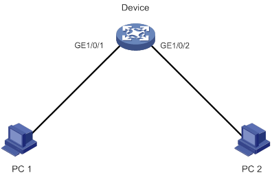
Scheduling procedure
# Enter system view.
<Sysname> system-view
# Configure a job for disabling interface GigabitEthernet 1/0/1.
[Sysname] scheduler job shutdown-GigabitEthernet1/0/1
[Sysname-job-shutdown-GigabitEthernet1/0/1] command 1 system-view
[Sysname-job-shutdown-GigabitEthernet1/0/1] command 2 interface gigabitethernet 1/0/1
[Sysname-job-shutdown-GigabitEthernet1/0/1] command 3 shutdown
[Sysname-job-shutdown-GigabitEthernet1/0/1] quit
# Configure a job for enabling interface GigabitEthernet 1/0/1.
[Sysname] scheduler job start-GigabitEthernet1/0/1
[Sysname-job-start-GigabitEthernet1/0/1] command 1 system-view
[Sysname-job-start-GigabitEthernet1/0/1] command 2 interface gigabitethernet 1/0/1
[Sysname-job-start-GigabitEthernet1/0/1] command 3 undo shutdown
[Sysname-job-start-GigabitEthernet1/0/1] quit
# Configure a job for disabling interface GigabitEthernet 1/0/2.
[Sysname] scheduler job shutdown-GigabitEthernet1/0/2
[Sysname-job-shutdown-GigabitEthernet1/0/2] command 1 system-view
[Sysname-job-shutdown-GigabitEthernet1/0/2] command 2 interface gigabitethernet 1/0/2
[Sysname-job-shutdown-GigabitEthernet1/0/2] command 3 shutdown
[Sysname-job-shutdown-GigabitEthernet1/0/2] quit
# Configure a job for enabling interface GigabitEthernet 1/0/2.
[Sysname] scheduler job start-GigabitEthernet1/0/2
[Sysname-job-start-GigabitEthernet1/0/2] command 1 system-view
[Sysname-job-start-GigabitEthernet1/0/2] command 2 interface gigabitethernet 1/0/2
[Sysname-job-start-GigabitEthernet1/0/2] command 3 undo shutdown
[Sysname-job-start-GigabitEthernet1/0/2] quit
# Configure a periodic schedule for enabling the interfaces at 8:00 a.m. every Monday through Friday.
[Sysname] scheduler schedule START-pc1/pc2
[Sysname-schedule-START-pc1/pc2] job start-GigabitEthernet1/0/1
[Sysname-schedule-START-pc1/pc2] job start-GigabitEthernet1/0/2
[Sysname-schedule-START-pc1/pc2] time repeating at 8:00 week-day mon tue wed thu fri
[Sysname-schedule-START-pc1/pc2] quit
# Configure a periodic schedule for disabling the interfaces at 18:00 every Monday through Friday.
[Sysname] scheduler schedule STOP-pc1/pc2
[Sysname-schedule-STOP-pc1/pc2] job shutdown-GigabitEthernet1/0/1
[Sysname-schedule-STOP-pc1/pc2] job shutdown-GigabitEthernet1/0/2
[Sysname-schedule-STOP-pc1/pc2] time repeating at 18:00 week-day mon tue wed thu fri
[Sysname-schedule-STOP-pc1/pc2] quit
Verifying the scheduling
# Display the configuration information of all jobs.
[Sysname] display scheduler job
Job name: shutdown-GigabitEthernet1/0/1
system-view
interface GigabitEthernet 1/0/1
shutdown
Job name: shutdown-GigabitEthernet1/0/2
system-view
interface GigabitEthernet 1/0/2
shutdown
Job name: start-GigabitEthernet1/0/1
system-view
interface GigabitEthernet 1/0/1
undo shutdown
Job name: start-GigabitEthernet1/0/2
system-view
interface GigabitEthernet 1/0/2
undo shutdown
# Display the schedule information.
[Sysname] display scheduler schedule
Schedule name : START-pc1/pc2
Schedule type : Run on every Mon Tue Wed Thu Fri at 08:00:00
Start time : Wed May 28 08:00:00 2016
Last execution time : Wed May 28 08:00:00 2016
Last completion time : Wed May 28 08:00:03 2016
Execution counts : 1
-----------------------------------------------------------------------
Job name Last execution status
start-GigabitEthernet1/0/1 Successful
start-GigabitEthernet1/0/2 Successful
Schedule name : STOP-pc1/pc2
Schedule type : Run on every Mon Tue Wed Thu Fri at 18:00:00
Start time : Wed May 28 18:00:00 2016
Last execution time : Wed May 28 18:00:00 2016
Last completion time : Wed May 28 18:00:01 2016
Execution counts : 1
-----------------------------------------------------------------------
Job name Last execution status
shutdown-GigabitEthernet1/0/1 Successful
shutdown-GigabitEthernet1/0/2 Successful
# Display schedule log information.
[Sysname] display scheduler logfile
Job name : start-GigabitEthernet1/0/1
Schedule name : START-pc1/pc2
Execution time : Wed May 28 08:00:00 2016
Completion time : Wed May 28 08:00:02 2016
--------------------------------- Job output -----------------------------------
<Sysname>system-view
System View: return to User View with Ctrl+Z.
[Sysname]interface GigabitEthernet 1/0/1
[Sysname-GigabitEthernet1/0/1]undo shutdown
Job name : start-GigabitEthernet1/0/2
Schedule name : START-pc1/pc2
Execution time : Wed May 28 08:00:00 2016
Completion time : Wed May 28 08:00:02 2016
--------------------------------- Job output -----------------------------------
<Sysname>system-view
System View: return to User View with Ctrl+Z.
[Sysname]interface GigabitEthernet 1/0/2.
[Sysname-GigabitEthernet1/0/2]undo shutdown
Job name : shutdown-GigabitEthernet1/0/1
Schedule name : STOP-pc1/pc2
Execution time : Wed May 28 18:00:00 2016
Completion time : Wed May 28 18:00:01 2016
--------------------------------- Job output -----------------------------------
<Sysname>system-view
System View: return to User View with Ctrl+Z.
[Sysname]interface GigabitEthernet 1/0/1
[Sysname-GigabitEthernet1/0/1]shutdown
Job name : shutdown-GigabitEthernet1/0/2
Schedule name : STOP-pc1/pc2
Execution time : Wed May 28 18:00:00 2016
Completion time : Wed May 28 18:00:01 2016
--------------------------------- Job output -----------------------------------
<Sysname>system-view
System View: return to User View with Ctrl+Z.
[Sysname]interface GigabitEthernet 1/0/2
[Sysname-GigabitEthernet1/0/2]shutdown
Disabling password recovery capability
Password recovery capability controls console user access to the device configuration and SDRAM from Boot ROM menus. For more information about Boot ROM menu options, see the release notes.
If password recovery capability is enabled, a console user can access the device configuration without authentication to configure a new password.
If password recovery capability is disabled, console users must restore the factory-default configuration before they can configure new passwords. Restoring the factory-default configuration deletes the next-startup configuration files.
To enhance system security, disable password recovery capability.
To disable password recovery capability:
|
Step |
Command |
Remarks |
|
1. Enter system view. |
system-view |
N/A |
|
2. Disable password recovery capability. |
undo password-recovery enable |
By default, password recovery capability is enabled. |
Managing power supply
|
|
IMPORTANT: For the power supplies and the device to operate correctly, do not install AC power supplies and DC power supplies on the same device. |
Power supplies might have problems such as overloading, overcurrent, overvoltage, overtemperature, and short circuit. Some power supplies use a hardware protection measure, for example, powering off the device, to protect the entire device from being damaged. The hardware protection measure helps protect the device but interrupts services. The power supply management feature can minimize service interruption while protecting the device against overloading problems.
The power supply management feature constantly monitors the available power and the system loads. If a potential power supply problem is found, this feature takes protective measures immediately to remove requirements for power supply hardware protection. Examples of protective measures include sending a notification, starting redundant power supplies, and powering off certain interface cards.
You can perform the following tasks for the power supply management feature:
· Enabling power supply management
· Specifying the number of redundant power supplies
You can also manually power on or off cards.
Enabling power supply management
The following matrix shows the feature and hardware compatibility:
|
Hardware |
Power supply management compatibility |
|
MSR810/810-W/810-W-DB/810-LM/810-W-LM/810-10-PoE/810-LM-HK/810-W-LM-HK/810-LMS/810-LUS |
No |
|
MSR2600-6-X1/2600-10-X1 |
No |
|
MSR 2630 |
No |
|
MSR3600-28/3600-51 |
No |
|
MSR3600-28-SI/3600-51-SI |
No |
|
MSR3610-X1/3610-X1-DP/3610-X1-DC/3610-X1-DP-DC |
No |
|
MSR 3610/3620/3620-DP/3640/3660 |
No |
|
MSR5620/5660/5680 |
Yes |
|
Hardware |
Power supply management compatibility |
|
MSR810-LM-GL |
No |
|
MSR810-W-LM-GL |
No |
|
MSR830-6EI-GL |
No |
|
MSR830-10EI-GL |
No |
|
MSR830-6HI-GL |
No |
|
MSR830-10HI-GL |
No |
|
MSR2600-6-X1-GL |
No |
|
MSR3600-28-SI-GL |
No |
To enable power supply management:
|
Step |
Command |
Remarks |
|
1. Enter system view. |
system-view |
N/A |
|
2. Enable power supply management. |
·
Distributed devices in standalone mode: ·
Distributed devices in IRF mode: |
By default, power supply management is disabled. |
Specifying the number of redundant power supplies
To avoid overload problems, you can install redundant power supplies. For example, if the device requires a minimum of N power supplies to operate correctly, you can install M power supplies (M > N). The M power supplies operates in load balance mode. When a power supply fails, the load is rebalanced among the other power supplies.
After you specify the number of redundant power supplies, the device compares the maximum power consumption of a newly added card with the remaining power.
· If the remaining power is sufficient for the card, the device powers on the card.
· If the power is insufficient, the device does not power on the card. You can add power supplies or scale the number of redundant power supplies down.
To specify the number of redundant power supplies:
|
Step |
Command |
Remarks |
|
1. Enter system view. |
system-view |
N/A |
|
2. Specify the number of redundant power supplies. |
·
Distributed devices in standalone
mode/centralized devices in IRF mode: ·
Distributed devices in IRF mode: |
By default, the number of redundant power supplies is 0. The configuration of this command takes effect only when power supply management is enabled. |
Powering on/off a card
You can manually power on or off cards. To view the power supply status, use the display power-supply command.
To power on or off a card, execute one of the following commands in user view as appropriate:
|
Task |
Command |
Remarks |
|
Power on a card. |
·
Distributed devices in standalone mode: ·
Distributed devices in IRF mode: |
N/A |
|
Power off a card. |
·
Distributed devices in standalone mode: ·
Distributed devices in IRF mode: |
To avoid IRF split, do not power off an interface card that contains all active physical IRF ports of a member device. |
Setting the port status detection timer
To set the port status detection timer:
|
Step |
Command |
Remarks |
|
1. Enter system view. |
system-view |
N/A |
|
2. Set the port status detection timer. |
shutdown-interval time |
The default setting is 30 seconds. |
Monitoring CPU usage
To monitor CPU usage, the device performs the following operations:
· Samples CPU usage at an interval of 1 minute, and compares the sample with the CPU usage threshold. If the sample is greater, the device sends a trap and notifies the relevant modules.
· Samples and saves CPU usage at a configurable interval if CPU usage tracking is enabled.
· Samples CPU core usage at an interval of 1 minute and compares the sample with the CPU core usage threshold. If the sample is greater than or equal to the CPU core usage threshold, the device determines that the CPU core usage is high and generates a log message.
To monitor CPU usage (centralized devices in standalone mode):
|
Command |
Remarks |
|
|
1. Enter system view. |
N/A |
|
|
2. Set the CPU usage threshold. |
monitor cpu-usage threshold cpu-threshold |
By default, the CPU usage threshold is 99%. |
|
3. Enable CPU usage tracking. |
By default, CPU usage tracking is enabled. |
|
|
4. Set the sampling interval for CPU usage tracking. |
By default, the sampling interval for CPU usage tracking is 1 minute. |
|
|
5. Exit to user view. |
N/A |
|
|
6. Display the current CPU usage statistics. |
display cpu-usage [ summary ] |
|
|
7. Display CPU usage monitoring settings. |
This command is available in any view. |
|
|
8. Display the historical CPU usage statistics in a coordinate system. |
This command is available in any view. |
To monitor CPU usage (distributed devices in standalone mode/centralized devices in IRF mode):
|
Command |
Remarks |
|
|
1. Enter system view. |
N/A |
|
|
2. Set the CPU usage threshold. |
monitor cpu-usage threshold cpu-threshold [ slot slot-number [ cpu cpu-number ] ] |
By default, the CPU usage threshold is 99%. |
|
3. Enable CPU usage tracking. |
By default, CPU usage tracking is enabled. |
|
|
4. Set the sampling interval for CPU usage tracking. |
By default, the sampling interval for CPU usage tracking is 1 minute. |
|
|
5. Exit to user view. |
N/A |
|
|
6. Display CPU usage statistics. |
display cpu-usage [ summary ] [ slot slot-number [ cpu cpu-number ] ] |
This command is available in any view. |
|
7. Display CPU usage monitoring settings. |
display cpu-usage configuration [ slot slot-number [ cpu cpu-number ] ] |
This command is available in any view. |
|
8. Display the historical CPU usage statistics in a coordinate system. |
display cpu-usage history [ job job-id ] [ slot slot-number [ cpu cpu-number ] ] |
This command is available in any view. |
To monitor CPU usage (distributed devices in IRF mode):
|
Command |
Remarks |
|
|
1. Enter system view. |
N/A |
|
|
2. Set the CPU usage threshold. |
monitor cpu-usage threshold cpu-threshold [ chassis chassis-number slot slot-number [ cpu cpu-number ] ] |
By default, the CPU usage threshold is 99%. |
|
3. Enable CPU usage tracking. |
monitor cpu-usage enable [ chassis chassis-number slot slot-number [ cpu cpu-number ] ] |
By default, CPU usage tracking is enabled. |
|
4. Set the sampling interval for CPU usage tracking. |
By default, the sampling interval for CPU usage tracking is 1 minute. |
|
|
5. Exit to user view. |
N/A |
|
|
6. Display CPU usage statistics. |
display cpu-usage [ summary ] [ chassis chassis-number slot slot-number [ cpu cpu-number ] ] |
This command is available in any view. |
|
7. Display CPU usage monitoring settings. |
display cpu-usage configuration [ chassis chassis-number slot slot-number [ cpu cpu-number ] ] |
This command is available in any view. |
|
8. Display the historical CPU usage statistics in a coordinate system. |
This command is available in any view. |
Setting memory alarm thresholds
To monitor memory usage, the device performs the following operations:
· Samples memory usage at an interval of 1 minute, and compares the sample with the memory usage threshold. If the sample is greater, the device sends a trap.
· Monitors the amount of free memory space in real time. If the amount of free memory space exceeds a free-memory threshold, the system generates an alarm notification and sends it to affected service modules or processes. If the amount of free memory space drops below a free-memory threshold, the system generates an alarm-removed notification and sends it to affected service modules or processes.
As shown in Table 17 and Figure 53, the system supports the following free-memory thresholds:
· Normal state threshold.
· Minor alarm threshold.
· Severe alarm threshold.
· Critical alarm threshold.
Table 17 Memory alarm notifications and memory alarm-removed notifications
|
Notification |
Triggering condition |
Remarks |
|
Minor alarm notification |
The amount of free memory space decreases to or below the minor alarm threshold for the first time. |
After generating and sending a minor alarm notification, the system does not generate and send any additional minor alarm notifications until the first minor alarm is removed. |
|
Severe alarm notification |
The amount of free memory space decreases to or below the severe alarm threshold for the first time. |
After generating and sending a severe alarm notification, the system does not generate and send any additional severe alarm notifications until the first severe alarm is removed. |
|
Critical alarm notification |
The amount of free memory space decreases to or below the critical alarm threshold for the first time. |
After generating and sending a critical alarm notification, the system does not generate and send any additional critical alarm notifications until the first critical alarm is removed. |
|
Critical alarm-removed notification |
The amount of free memory space increases to or above the severe alarm threshold. |
N/A |
|
Severe alarm-removed notification |
The amount of free memory space increases to or above the minor alarm threshold. |
N/A |
|
Minor alarm-removed notification |
The amount of free memory space increases to or above the normal state threshold. |
N/A |
Figure 53 Memory alarm notifications and alarm-removed notifications
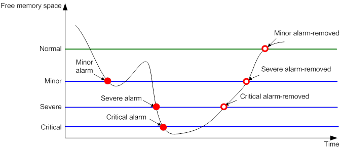
To set memory alarm thresholds:
|
Step |
Command |
Remarks |
|
1. Enter system view. |
system-view |
N/A |
|
2. Set the memory usage threshold. |
·
Centralized devices in standalone mode: ·
Distributed devices in standalone
mode/centralized devices in IRF mode: ·
Distributed devices in IRF mode: |
By default, the memory usage threshold is 100%. |
|
3. Set the free-memory thresholds. |
·
Centralized devices in standalone mode: ·
Distributed devices in standalone
mode/centralized devices in IRF mode: ·
Distributed devices in IRF mode: |
For information about the default free-memory thresholds, see Fundamentals Command Reference. |
Disabling all USB interfaces
You can use USB interfaces to upload or download files or to connect a 3G modem. By default, all USB interfaces are enabled. You can disable USB interfaces as needed.
To disable all USB interfaces:
|
Step |
Command |
Remarks |
|
1. Enter system view. |
system-view |
N/A |
|
2. Disable all USB interfaces. |
usb disable |
By default, all USB interfaces are enabled. Before using this command, use the umount command to unmount all USB file systems. For more information about this command, see Fundamentals Command Reference. |
Setting the operating mode for an interface card
The following matrix shows the feature and hardware compatibility:
|
Hardware |
Operating mode setting compatibility |
|
MSR810/810-W/810-W-DB/810-LM/810-W-LM/810-10-PoE/810-LM-HK/810-W-LM-HK/810-LMS/810-LUS |
No |
|
MSR2600-6-X1/2600-10-X1 |
Yes |
|
MSR 2630 |
Yes |
|
MSR3600-28/3600-51 |
No |
|
MSR3600-28-SI/3600-51-SI |
No |
|
MSR3610-X1/3610-X1-DP/3610-X1-DC/3610-X1-DP-DC |
No |
|
MSR 3610/3620/3620-DP/3640/3660 |
Yes |
|
MSR5620/5660/5680 |
Yes |
|
Hardware |
Operating mode setting compatibility |
|
MSR810-LM-GL |
No |
|
MSR810-W-LM-GL |
No |
|
MSR830-6EI-GL |
No |
|
MSR830-10EI-GL |
No |
|
MSR830-6HI-GL |
No |
|
MSR830-10HI-GL |
No |
|
MSR2600-6-X1-GL |
Yes |
|
MSR3600-28-SI-GL |
Yes |
Some interface cards can operate in multiple modes to provide different types of interfaces.
To set the operating mode for an interface card:
|
Step |
Command |
Remarks |
|
1. Enter system view. |
system-view |
N/A |
|
2. Set the operating mode for an interface card. |
·
Centralized devices in standalone mode ·
Centralized devices in IRF mode ·
Distributed devices in standalone mode: ·
Distributed devices in IRF mode: |
For the new setting to take effect, you must perform one of the following tasks to activate the setting: · Restart the device. · Hot swap the interface card if the interface card supports hot swapping. |
Verifying and diagnosing transceiver modules
Verifying transceiver modules
You can use one of the following methods to verify the genuineness of a transceiver module:
· Display the key parameters of a transceiver module, including its transceiver type, connector type, central wavelength of the transmit laser, transfer distance, and vendor name.
· Display its electronic label. The electronic label is a profile of the transceiver module and contains the permanent configuration, including the serial number, manufacturing date, and vendor name. The data is written to the storage component during debugging or testing.
Install only transceiver modules that are from H3C. If you install a transceiver module that is not from H3C, the device will generate a log message to prompt you to replace the module. For more information about log messages, see information center configuration in Network Management and Monitoring Configuration Guide.
To verify transceiver modules, execute the following commands in any view:
|
Task |
Command |
|
Display the key parameters of transceiver modules. |
display transceiver interface [ interface-type interface-number ] |
|
Display the electrical label information of transceiver modules. |
display transceiver manuinfo interface [ interface-type interface-number ] |
Diagnosing transceiver modules
The device provides the alarm and digital diagnosis functions for transceiver modules. When a transceiver module fails or is not operating correctly, you can perform the following tasks:
· Check the alarms that exist on the transceiver module to identify the fault source.
· Examine the key parameters monitored by the digital diagnosis function, including the temperature, voltage, laser bias current, TX power, and RX power.
To diagnose transceiver modules, execute the following commands in any view:
|
Task |
Command |
|
Display transceiver alarms. |
display transceiver alarm interface [ interface-type interface-number ] |
|
Display the current values of the digital diagnosis parameters on transceiver modules. |
display transceiver diagnosis interface [ interface-type interface-number ] |
Restoring the factory-default configuration
|
|
CAUTION: This task is disruptive. Use this task only when you cannot troubleshoot the device by using other methods, or you want to use the device in a different scenario. |
|
Command |
Remarks |
|
|
Restore the factory-default configuration for the device. |
This command takes effect after a device reboot. |
Unmounting HMIM modules
|
|
CAUTION: Unmounting an HMIM module stops all services provided by the module. |
The following matrix shows the feature and hardware compatibility:
|
Hardware |
HMIM unmounting compatibility |
|
MSR810/810-W/810-W-DB/810-LM/810-W-LM/810-10-PoE/810-LM-HK/810-W-LM-HK/810-LMS/810-LUS |
No |
|
MSR2600-6-X1 |
Yes |
|
MSR2600-10-X1 |
No |
|
MSR 2630 |
No |
|
MSR3600-28/3600-51 |
No |
|
MSR3600-28-SI/3600-51-SI |
No |
|
MSR3610-X1/3610-X1-DP/3610-X1-DC/3610-X1-DP-DC |
Yes |
|
MSR 3610/3620/3620-DP/3640/3660 |
Yes |
|
MSR5620/5660/5680 |
Yes |
|
Hardware |
HMIM unmounting compatibility |
|
MSR810-LM-GL |
No |
|
MSR810-W-LM-GL |
No |
|
MSR830-6EI-GL |
No |
|
MSR830-10EI-GL |
No |
|
MSR830-6HI-GL |
No |
|
MSR830-10HI-GL |
No |
|
MSR2600-6-X1-GL |
Yes |
|
MSR3600-28-SI-GL |
No |
Use this feature to unmount an HMIM module before removing the module from the device. If you remove an HMIM module that is not unmounted, the device might fail or be damaged.
An unmounted HMIM module is not visible or configurable.
To unmount an HMIM module, execute the following command in user view:
|
Task |
Command |
|
Unmount an HMIM module. |
·
Centralized devices in standalone mode: ·
Distributed devices in standalone
mode/centralized devices in IRF mode: ·
Distributed devices in IRF mode: |
Updating the modem firmware through FoTA
Currently, this feature is supported only on the following devices:
· MSR810-LMS
· MSR810-LUS
· Devices that are installed with the SIC-D4G-CNED or SIC-4G-CNED card.
Use this command with caution. A modem firmware update through FoTA affects data transmission and consumes SIM card resources.
To update the modem firmware through FoTA:
|
Step |
Command |
|
1. Enter system view. |
system-view |
|
2. Enter cellular interface view. |
controller cellular cellular-number |
|
3. Update the modem firmware through FoTA. |
firmware update fota |
Displaying and maintaining device management configuration
Execute display commands in any view. Execute reset commands in user view.
Centralized devices in standalone mode:
|
Task |
Command |
|
Display device alarm information. |
display alarm [ slot slot-number ] |
|
Display the system time, date, local time zone, and daylight saving time. |
display clock |
|
Display the copyright statement. |
display copyright |
|
Display CPU usage statistics. |
display cpu-usage |
|
Display historical CPU usage statistics. |
display cpu-usage history [ job job-id ] |
|
Display hardware information. |
display device [ cf-card | harddisk | sd-card | usb ] [ slot slot-number | verbose ] |
|
Display electronic label information for the device. |
display device manuinfo [ slot slot-number ] |
|
Display electronic label information for a power supply. |
display device manuinfo power power-id |
|
Display or save device operating information. |
display diagnostic-information [ hardware | infrastructure | l2 | l3 | service ] [ key-info ] [ filename ] |
|
Display device temperature information. |
display environment |
|
Display the operating states of fans. |
display fan [ fan-id | verbose ] |
|
Display memory usage statistics. |
display memory [ summary ] |
|
Display memory alarm thresholds and statistics. |
display memory-threshold |
|
Display power supply information. |
display power-supply [ verbose ] |
|
Display job configuration information. |
display scheduler job [ job-name ] |
|
Display job execution log information. |
display scheduler logfile |
|
Display the automatic reboot schedule. |
display scheduler reboot |
|
Display schedule information. |
display scheduler schedule [ schedule-name ] |
|
Display system stability and status information. |
|
|
Display system version information. |
display version |
|
Display the startup software image upgrade records. |
display version-update-record |
|
Clear job execution log information. |
reset scheduler logfile |
Distributed devices in standalone mode/centralized devices in IRF mode:
|
Task |
Command |
|
Display device alarm information. |
display alarm [ slot slot-number ] |
|
Display SPU operating mode information (distributed devices in standalone mode). |
display card-forwarding-mode |
|
Display the system time, date, local time zone, and daylight saving time. |
display clock |
|
Display the copyright statement. |
display copyright |
|
Display CPU usage statistics. |
display cpu-usage [ slot slot-number [ cpu cpu-number ] ] |
|
Display historical CPU usage statistics in a chart. |
display cpu-usage history [ job job-id ] [ slot slot-number [ cpu cpu-number ] ] |
|
Display hardware information. |
display device [ cf-card | harddisk | sd-card | usb ] [ slot slot-number [ subslot subslot-number ] | verbose ] |
|
Display electronic label information for the device. |
display device manuinfo [ slot slot-number [ subslot subslot-number ] ] |
|
Display electronic label information for a fan (centralized devices in IRF mode). |
display device manuinfo slot slot-number fan fan-id |
|
Display electronic label information for a power supply (distributed devices in standalone mode). |
display device manuinfo power power-id |
|
Display electronic label information for a power supply (centralized devices in IRF mode). |
display device manuinfo slot slot-number power power-id |
|
Display electronic label information for a power monitoring module (centralized devices in IRF mode). |
display device manuinfo slot slot-number power-monitor pm-id |
|
Display or save device operating information. |
display diagnostic-information [ hardware | infrastructure | l2 | l3 | service ] [ key-info ] [ filename ] |
|
Display device temperature information. |
display environment [ slot slot-number ] |
|
Display the operating states of fans (distributed devices in standalone mode). |
display fan [ fan-id ] |
|
Display the operating states of fans (centralized devices in IRF mode). |
display fan [ slot slot-number [ fan-id ] ] |
|
Display memory usage statistics. |
display memory [ summary ] [ slot slot-number [ cpu cpu-number ] ] |
|
Display memory alarm thresholds and statistics. |
display memory-threshold [ slot slot-number [ cpu cpu-number ] ] |
|
Display power supply information (distributed devices in standalone mode). |
display power-supply [ verbose ] |
|
Display power supply information (centralized devices in IRF mode). |
display power-supply [ slot slot-number ] [ verbose ] |
|
Display job configuration information. |
display scheduler job [ job-name ] |
|
Display job execution log information. |
display scheduler logfile |
|
Display the automatic reboot schedule. |
display scheduler reboot |
|
Display schedule information. |
display scheduler schedule [ schedule-name ] |
|
Display system stability and status information. |
display system stable state |
|
Display system version information. |
display version |
|
Display the startup software image upgrade records of the active MPU (distributed devices in standalone mode). |
display version-update-record |
|
Display the startup software image upgrade records of the master (centralized devices in IRF mode). |
display version-update-record |
|
Clear job execution log information. |
reset scheduler logfile |
Distributed devices in IRF mode:
|
Task |
Command |
|
Display device alarm information. |
display alarm [ chassis chassis-number slot slot-number ] |
|
Display the system time ,date, local time zone, and daylight saving time. |
display clock |
|
Display the copyright statement. |
display copyright |
|
Display CPU usage statistics. |
display cpu-usage [ chassis chassis-number slot slot-number [ cpu cpu-number ] ] |
|
Display historical CPU usage statistics in a chart. |
display cpu-usage history [ job job-id ] [ chassis chassis-number slot slot-number [ cpu cpu-number ] ] |
|
Display hardware information. |
display device [ cf-card | harddisk | sd-card | usb ] [ chassis chassis-number [ slot slot-number [ subslot subslot-number ] ] | verbose ] |
|
Display electronic label information for the device. |
display device manuinfo [ chassis chassis-number [ slot slot-number [ subslot subslot-number ] ] ] |
|
Display electronic label information for a fan |
display device manuinfo chassis chassis-number fan fan-id |
|
Display electronic label information for a power supply |
display device manuinfo chassis chassis-number power power-id |
|
Display electronic label information for a power monitoring module |
display device manuinfo chassis chassis-number power-monitor pm-id |
|
Display or save device operating information. |
display diagnostic-information [ hardware | infrastructure | l2 | l3 | service ] [ key-info ] [ filename ] |
|
Display device temperature information. |
display environment [ chassis chassis-number [ slot slot-number ] ] |
|
Display the operating states of fans |
display fan [ chassis chassis-number [ fan-id ] ] |
|
Display memory usage statistics. |
display memory [ summary ] [ chassis chassis-number slot slot-number [ cpu cpu-number ] ] |
|
Display memory alarm thresholds and statistics. |
display memory-threshold [ chassis chassis-number slot slot-number [ cpu cpu-number ] ] |
|
Display power supply information. |
display power-supply [ chassis chassis-number ] [ verbose ] |
|
Display job configuration information. |
display scheduler job [ job-name ] |
|
Display job execution log information. |
display scheduler logfile |
|
Display the automatic reboot schedule. |
display scheduler reboot |
|
Display schedule information. |
display scheduler schedule [ schedule-name ] |
|
Display system stability and status information. |
display system stable state |
|
Display system version information. |
display version |
|
Display the startup software image upgrade records of the global active MPU. |
display version-update-record |
|
Clear job execution log information. |
reset scheduler logfile |
Using Tcl
Comware 7 provides a built-in tool command language (Tcl) interpreter. From user view, you can use the tclsh command to enter Tcl configuration view to execute the following commands:
· All Tcl 8.5 commands.
· Comware commands.
The Tcl configuration view is equivalent to the user view. You can use Comware commands in Tcl configuration view in the same way they are used in user view. For example, you can perform the following tasks:
? Use the system-view command to enter system view to configure features.
? Use the quit command to return to the upper-level view.
Using Tcl to configure the device
When you use Tcl to configure the device, follow these guidelines and restrictions:
· You can apply Tcl environment variables to Comware commands.
· No online help information is provided for Tcl commands.
· You cannot press Tab to complete an abbreviated Tcl command.
· As a best practice, log in through Telnet or SSH. You cannot stop Tcl commands by using a shortcut key or a CLI command. If a problem occurs when the Tcl commands are being executed, you can terminate the process by closing the connection if you logged in through Telnet or SSH. If you logged in from the console or AUX port, you must perform one of the following tasks:
? Restart the device.
? Log in to the device by using a different method, and use the free line command to release the console or AUX line. For more information about the command, see Fundamentals Command Reference.
· You can press Ctrl+D to abort Tcl command read stdin.
To use Tcl to configure the device:
|
Task |
Command |
|
Enter Tcl configuration view from user view. |
tclsh |
|
Execute a Tcl command. |
Tcl command |
|
Return from Tcl configuration view to user view. |
tclquit |
|
|
NOTE: · The tclquit command has the same effect as the quit command in Tcl configuration view. · If you have used a Comware command to enter a subview under Tcl configuration view, you can only use the quit command, instead of the tclquit command, to return to the upper-level view. |
Executing Comware commands in Tcl configuration view
Follow these restrictions and guidelines when you execute Comware commands in Tcl configuration view:
· To specify a string enclosed in quotation marks (") or braces ({ and }), you must use the escape character (\) before the quotation marks or braces. For example, to specify "a" as the description for an interface, you must enter description \"a\". If you enter description "a", the description is a.
· For Comware commands, you can enter ? to obtain online help or press Tab to complete an abbreviated command. For more information, see "Using the CLI."
· The cli command is a Tcl command, so you cannot enter ? to obtain online help or press Tab to complete an abbreviated command.
· Successfully executed Comware commands are saved to command history buffers. You can use the upper arrow or lower arrow key to obtain executed commands.
· To execute multiple Comware commands in one operation:
? Enter multiple Comware commands separated by semi-colons to execute the commands in the order they are entered. For example, ospf 100;area 0.
? Specify multiple Comware commands for the cli command, quote them, and separate them by a space and a semicolon. For example, cli "ospf 100 ; area 0".
? Specify one Comware command for each cli command and separate them by a space and a semicolon. For example, cli ospf 100 ; cli area 0.
To execute Comware commands in Tcl configuration view:
|
Step |
Command |
Remarks |
|
1. Enter Tcl configuration view |
tclsh |
N/A |
|
2. Execute Comware commands directly. |
Command |
Use either method. If you execute a Comware command directly, a Tcl command is executed when the Tcl command conflicts with the Comware command. If you execute a Comware command by using the cli command, the Comware command is executed when it conflicts with a Tcl command. |
|
3. Execute Comware commands by using the cli command. |
cli command |
Using Python
Overview
Comware 7 provides a built-in Python interpreter that supports the following items:
· Python 2.7 commands.
· Python 2.7 standard API.
· Comware 7 extended API. For more information about the Comware 7 extended API, see "Comware 7 extended Python API."
· Python scripts. You can use a Python script to configure the system.
Compatibility information
Feature and hardware compatibility
The following matrix shows the feature and hardware compatibility:
|
Hardware |
Security zone compatibility |
|
MSR810/810-W/810-W-DB/810-LM/810-W-LM/810-10-PoE/810-LM-HK/810-W-LM-HK/810-LMS/810-LUS |
Yes except on MSR810-LMS/810-LUS |
|
MSR2600-6-X1/2600-10-X1 |
Yes |
|
MSR 2630 |
Yes |
|
MSR3600-28/3600-51 |
Yes |
|
MSR3600-28-SI/3600-51-SI |
No |
|
MSR3610-X1/3610-X1-DP/3610-X1-DC/3610-X1-DP-DC |
Yes |
|
MSR 3610/3620/3620-DP/3640/3660 |
Yes |
|
MSR5620/5660/5680 |
Yes |
|
Hardware |
Security zone compatibility |
|
MSR810-LM-GL |
Yes |
|
MSR810-W-LM-GL |
Yes |
|
MSR830-6EI-GL |
Yes |
|
MSR830-10EI-GL |
Yes |
|
MSR830-6HI-GL |
Yes |
|
MSR830-10HI-GL |
Yes |
|
MSR2600-6-X1-GL |
Yes |
|
MSR3600-28-SI-GL |
No |
Command and hardware compatibility
Commands and descriptions for centralized devices apply to the following routers:
· MSR810/810-W/810-W-DB/810-LM/810-W-LM/810-10-PoE/810-LM-HK/810-W-LM-HK/810-LMS/810-LUS.
· MSR2600-6-X1/2600-10-X1.
· MSR 2630.
· MSR3600-28/3600-51.
· MSR3600-28-SI/3600-51-SI.
· MSR3610-X1/3610-X1-DP/3610-X1-DC/3610-X1-DP-DC.
· MSR 3610/3620/3620-DP/3640/3660.
· MSR810-LM-GL/810-W-LM-GL/830-6EI-GL/830-10EI-GL/830-6HI-GL/830-10HI-GL/2600-6-X1-GL/3600-28-SI-GL.
Commands and descriptions for distributed devices apply to the following routers:
· MSR5620.
· MSR 5660.
· MSR 5680.
Entering the Python shell
To use Python commands and APIs, you must enter the Python shell.
|
Command |
|
|
Enter the Python shell from user view. |
Executing a Python script
Execute a Python script in user view.
|
Command |
|
|
Execute a Python script. |
Python usage example
Network requirements
Use a Python script to perform the following tasks:
· Download configuration files main.cfg and backup.cfg to the device.
· Configure the files as the main and backup configuration files for the next startup.
Figure 54 Network diagram
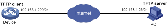
Usage procedure
# Use a text editor on the PC to edit Python script test.py as follows:
comware.Transfer('tftp', '192.168.1.26', 'main.cfg', 'flash:/main.cfg')
comware.Transfer('tftp', '192.168.1.26', 'backup.cfg', 'flash:/backup.cfg')
comware.CLI('startup saved-configuration flash:/main.cfg main ;startup saved-configuration flash:/backup.cfg backup')
# Use TFTP to download the script to the device.
<Sysname> tftp 192.168.1.26 get test.py
<Sysname> python flash:/test.py
<Sysname> startup saved-configuration flash:/main.cfg main
Please wait...... Done.
<Sysname> startup saved-configuration flash:/backup.cfg backup
Please wait...... Done.
Verifying the configuration
# Display startup configuration files.
Current startup saved-configuration file: flash:/startup.cfg
Next main startup saved-configuration file: flash:/main.cfg
Next backup startup saved-configuration file: flash:/backup.cfg
Comware 7 extended Python API
The Comware 7 extended Python API is compatible with the Python syntax.
Importing and using the Comware 7 extended Python API
To use the Comware 7 extended Python API, you must import the API to Python.
Use either of the following methods to import and use the Comware 7 extended Python API:
· Use import comware to import the entire API and use comware.API to execute an API.
For example, to use the extended API Transfer to download the test.cfg file from TFTP server 192.168.1.26:
Python 2.7.3 (default)
[GCC 4.4.1] on linux2
Type "help", "copyright", "credits" or "license" for more information.
>>> import comware
>>> comware.Transfer('tftp', '192.168.1.26', 'test.cfg', 'flash:/test.cfg', user='', password='')
<comware.Transfer object at 0xb7eab0e0>
· Use from comware import API to import an API and use API to execute the API.
For example, to use the extended API Transfer to download the test.cfg file from TFTP server 192.168.1.26:
Python 2.7.3 (default)
[GCC 4.4.1] on linux2
Type "help", "copyright", "credits" or "license" for more information.
>>> from comware import Transfer
>>> Transfer('tftp', '192.168.1.26', 'test.cfg', 'flash:/test.cfg', user='', password='')
<comware.Transfer object at 0xb7e5e0e0>
Comware 7 extended Python API functions
CLI class
CLI
Use CLI to execute Comware 7 CLI commands and create CLI objects.
Syntax
CLI(command=‘’, do_print=True)
Parameters
command: Specifies the commands to be executed. To enter multiple commands, use a space and a semicolon (;) as the delimiter. To enter a command in a view other than user view, you must first enter the commands used to enter the view. For example, you must enter ’system-view ;local-user test class manage’ to execute the local-user test class manage command.
do_print: Specifies whether to output the execution result:
· True—Outputs the execution result. This value is the default.
· False—Does not output the execution result.
Usage guidelines
This API supports only Comware commands. It does not support Linux, Python, or Tcl commands.
Returns
CLI objects
Examples
# Add a local user with the username test.
Python 2.7.3 (default)
[GCC 4.4.1] on linux2
Type "help", "copyright", "credits" or "license" for more information.
>>> import comware
>>> comware.CLI('system-view ;local-user test class manage')
System View: return to User View with Ctrl+Z.
[Sysname] local-user test class manage
New local user added.
<comware.CLI object at 0xb7f680a0>
get_output
Use get_output to get the output from executed commands.
Syntax
Returns
Output from executed commands
Examples
# Add a local user and get the output from the command.
Python 2.7.3 (default)
[GCC 4.4.1] on linux2
Type "help", "copyright", "credits" or "license" for more information.
>>> import comware
>>> c = comware.CLI('system-view ;local-user test class manage', False)
>>> c.get_output()
Sample output
Transfer class
Transfer
Use Transfer to download a file from a server.
Syntax
Transfer(protocol=‘’, host=‘’, source=‘’, dest=‘’, vrf=‘’,login_timeout=10, user=‘’, password=‘’)
Parameters
protocol: Specifies the protocol used to download a file:
host: Specifies the IP address of the remote server.
source: Specifies the name of the file to be downloaded from the remote server.
dest: Specifies a name for the downloaded file.
login_timeout: Specifies the timeout for the operation, in seconds. The default is 10.
user: Specifies the username for logging in to the server.
password: Specifies the login password.
Returns
Transfer object
Examples
# Download the test.cfg file from TFTP server 192.168.1.26.
Python 2.7.3 (default)
[GCC 4.4.1] on linux2
Type "help", "copyright", "credits" or "license" for more information.
>>> import comware
>>> comware.Transfer('tftp', '192.168.1.26', 'test.cfg', 'flash:/test.cfg', user='', password='')
Sample output
<comware.Transfer object at 0xb7f700e0>
get_error
Use get_error to get the error information from the download operation.
Syntax
Returns
Error information (if there is no error information, None is returned)
Examples
# Download the test.cfg file from TFTP server 1.1.1.1 and get the error information from the operation.
Python 2.7.3 (default)
[GCC 4.4.1] on linux2
Type "help", "copyright", "credits" or "license" for more information.
>>> import comware
>>> c = comware.Transfer('tftp', '1.1.1.1', 'test.cfg', 'flash:/test.cfg', user='', password='')
>>> c.get_error()
Sample output
API get_self_slot
get_self_slot
Use get_self_slot to get the slot number of the active MPU. (Centralized devices in standalone mode.)
Use get_self_slot to get the slot number of the active MPU. (Distributed devices in standalone mode.)
Use get_self_slot to get the member ID of the master device. (Centralized devices in IRF mode.)
Use get_self_slot to get the slot number of the global active MPU. (Distributed devices in IRF mode.)
Syntax
Returns
The return is always [-1,-1]. A centralized device does not have an active MPU. (Centralized devices in standalone mode.)
A list object in the format of [-1,slot-number]. The slot-number indicates the slot number of the active MPU. (Distributed devices in standalone mode.)
A list object in the format of [chassis-number,slot-number]. The chassis-number and slot-number indicate the member ID of the master device and the slot number of the global active MPU on the master device. (Distributed devices in IRF mode.)
Examples
# (Distributed devices in IRF mode.) Get the slot number of the global active MPU.
Python 2.7.3 (default)
[GCC 4.4.1] on linux2
Type "help", "copyright", "credits" or "license" for more information.
>>> import comware
>>> comware.get_self_slot()
API get_standby_slot
get_standby_slot
Use get_standby_slot to get the slot number of the standby MPU. (Centralized devices in standalone mode.)
Use get_standby_slot to get the slot number of the standby MPU. (Distributed devices in standalone mode.)
Use get_standby_slot to get the member IDs of the subordinate devices. (Centralized devices in IRF mode.)
Use get_standby_slot to get the slot numbers of the global standby MPUs. (Distributed devices in IRF mode.)
Syntax
Returns
The return is always [ ]. A centralized device does not have a standby MPU. (Centralized devices in standalone mode.)
A list object in the format of [[-1,slot-number]]. The slot-number indicates the slot number of a standby MPU. If the device does not have a standby MPU, [ ] is returned. (Distributed devices in standalone mode.)
A list object in one of the following formats:
· [ ]—The IRF fabric does not have a subordinate device.
· [[-1,slot-number]]—The IRF fabric has only one subordinate device.
· [[-1,slot-number1],[-1,slot-number2],...]—The IRF fabric has multiple subordinate devices.
The slot-number arguments indicate the member IDs of the subordinate devices. (Centralized devices in IRF mode.)
A list object in one of the following formats:
· [ ]—The IRF fabric does not have a global standby MPU.
· [[chassis-number,slot-number]]—The IRF fabric has only one global standby MPU.
· [[chassis-number1,slot-number1],[chassis-number2,slot-number2],…]—The IRF fabric has multiple standby MPUs.
The chassis-number and slot-number arguments indicate the device member IDs and slot numbers of the global standby MPUs. (Distributed devices in IRF mode.)
Examples
# (Centralized devices in IRF mode.) Get the member IDs of the subordinate devices.
Python 2.7.3 (default)
[GCC 4.4.1] on linux2
Type "help", "copyright", "credits" or "license" for more information.
>>> import comware
>>> comware.get_standby_slot()
Sample output
API get_slot_range
get_slot_range
Use get_slot_range to get the supported slot number range.
get_slot_range()
A dictionary object in the format of {'MaxSlot': max-slot-number, 'MinSlot': min-slot-number }. The max-slot-number argument indicates the maximum slot number. The min-slot-number argument indicates the minimum slot number.
# Get the supported slot number range.
Python 2.7.3 (default)
[GCC 4.4.1] on linux2
Type "help", "copyright", "credits" or "license" for more information.
>>> import comware
>>> comware. get_slot_range()
{'MaxSlot': 7, 'MinSlot': 0}
API get_slot_info
get_slot_info
Use get_slot_info to get information about a card. (Distributed devices in standalone or IRF mode.)
get_slot_info()
A dictionary object in the format of {'Slot': slot-number, 'Status': 'status', 'Chassis': chassis-number, 'Role': 'role', 'Cpu': CPU-number }. The slot-number argument indicates the slot number of the card. The status argument indicates the status of the card. The chassis-number argument indicates the member ID of the device. The role argument indicates the role of the card. The CPU-number argument indicates the ID of the main CPU, and it is fixed at 0.
# Get information about a card.
<Sysname> python
Python 2.7.3 (default)
[GCC 4.4.1] on linux2
Type "help", "copyright", "credits" or "license" for more information.
>>> import comware
>>> comware.get_slot_info(1)
{'Slot': 1, 'Status': 'Normal', 'Chassis': 0, 'Role': 'Master', 'Cpu': 0}
Managing licenses
Overview
Licenses for H3C MSR routers include package licenses and feature licenses.
H3C website provides the same license registration procedure for package licenses and feature licenses. For information about license registration, see "Registering licenses."
For information about license activation, see "Activating licenses."
Package license
The following matrix shows the feature and hardware compatibility:
|
Hardware |
Package license compatibility |
|
MSR810/810-W/810-W-DB/810-LM/810-W-LM/810-10-PoE/810-LM-HK/810-W-LM-HK/810-LMS/810-LUS |
No |
|
MSR2600-6-X1/2600-10-X1 |
No |
|
MSR 2630 |
Yes |
|
MSR3600-28/3600-51 |
Yes |
|
MSR3600-28-SI/3600-51-SI |
No |
|
MSR3610-X1/3610-X1-DP/3610-X1-DC/3610-X1-DP-DC |
No |
|
MSR 3610/3620/3640/3660 |
Yes |
|
MSR3620-DP |
No |
|
MSR5620 |
No |
|
MSR 5660/5680 |
Yes |
|
Hardware |
Package license compatibility |
|
MSR810-LM-GL |
No |
|
MSR810-W-LM-GL |
No |
|
MSR830-6EI-GL |
No |
|
MSR830-10EI-GL |
No |
|
MSR830-6HI-GL |
No |
|
MSR830-10HI-GL |
No |
|
MSR2600-6-X1-GL |
No |
|
MSR3600-28-SI-GL |
No |
|
|
NOTE: In this document, "No" indicates that the features restricted by the license can function correctly on the routers even though the license is not installed on the routers. |
H3C MSR router software image includes the following software:
· Boot ROM image
· System image
· Feature packages:
? Data feature package—Includes the features such as MPLS and DLSw.
? Security feature package—Includes the features such as VPN.
? Voice feature package—Includes the features such as BUSYOUT and voice.
The Boot ROM image and system image are required for the system to work, and they do not need any licenses. For more information about software images, see "Upgrading software."
The feature packages are all license-based features. You must register and activate the license for a feature to run on your device.
After a package license is correctly installed, the system will automatically search the storage media for a matching feature package. If no match is found, you are required to load the feature package and install it. If a match is found, the system will install the feature package. If the installation fails because of device poweroff or reboot, you are required to manually install the feature package when the device is powered on again. Use the display boot-loader command to verify that the feature package is installed successfully.
|
|
IMPORTANT: During the installation of feature packages, do not execute the save command. The violation will cause configuration loss. |
Feature license
ATC license
The following matrix shows the feature and hardware compatibility:
|
Hardware |
ATC license compatibility |
|
MSR810/810-W/810-W-DB/810-LM/810-W-LM/810-10-PoE/810-LM-HK/810-W-LM-HK/810-LMS/810-LUS |
No |
|
MSR2600-6-X1/2600-10-X1 |
No |
|
MSR 2630 |
No |
|
MSR3600-28/3600-51 |
Yes |
|
MSR3600-28-SI/3600-51-SI |
No |
|
MSR3610-X1/3610-X1-DP/3610-X1-DC/3610-X1-DP-DC |
Yes |
|
MSR 3610/3620/3620-DP/3640/3660 |
Yes |
|
MSR5620/5660/5680 |
Yes |
|
Hardware |
ATC license compatibility |
|
MSR810-LM-GL |
No |
|
MSR810-W-LM-GL |
No |
|
MSR830-6EI-GL |
No |
|
MSR830-10EI-GL |
No |
|
MSR830-6HI-GL |
No |
|
MSR830-10HI-GL |
No |
|
MSR2600-6-X1-GL |
No |
|
MSR3600-28-SI-GL |
No |
To use the RTC terminal access feature, you must install ATC licenses.
IP POS license
The following matrix shows the feature and hardware compatibility:
|
Hardware |
IP POS license compatibility |
|
MSR810/810-W/810-W-DB/810-LM/810-W-LM/810-10-PoE/810-LM-HK/810-W-LM-HK/810-LMS/810-LUS |
No |
|
MSR2600-6-X1/2600-10-X1 |
No |
|
MSR 2630 |
No |
|
MSR3600-28/3600-51 |
No |
|
MSR3600-28-SI/3600-51-SI |
No |
|
MSR3610-X1/3610-X1-DP/3610-X1-DC/3610-X1-DP-DC |
No |
|
MSR 3610/3620/3620-DP/3640/3660 |
No |
|
MSR5620/5660/5680 |
Yes |
|
Hardware |
IP POS license compatibility |
|
MSR810-LM-GL |
No |
|
MSR810-W-LM-GL |
No |
|
MSR830-6EI-GL |
No |
|
MSR830-10EI-GL |
No |
|
MSR830-6HI-GL |
No |
|
MSR830-10HI-GL |
No |
|
MSR2600-6-X1-GL |
No |
|
MSR3600-28-SI-GL |
No |
To establish TCP connections with POS terminals, you must install IP POS licenses on the device. The IP POS licenses control the number of TCP connections established between the device and POS terminals. When the device is installed with an IP POS license, the device is allowed to establish a maximum of 256 TCP connections with POS terminals. You can increase the number of allowed TCP connections by installing multiple IP POS licenses.
The E1POS interface modules are not subject to IP POS licenses. An E1POS interface module can function correctly even if no IP POS licenses are installed.
AC license
The following matrix shows the feature and hardware compatibility:
|
Hardware |
AC license compatibility |
|
MSR810/810-W/810-W-DB/810-LM/810-W-LM/810-10-PoE/810-LM-HK/810-W-LM-HK |
Yes |
|
MSR810-LMS/810-LUS |
No |
|
MSR2600-6-X1/2600-10-X1 |
Yes |
|
MSR 2630 |
Yes |
|
MSR3600-28/3600-51 |
Yes |
|
MSR3600-28-SI/3600-51-SI |
No |
|
MSR3610-X1/3610-X1-DP/3610-X1-DC/3610-X1-DP-DC |
Yes |
|
MSR 3610/3620/3620-DP/3640/3660 |
Yes |
|
MSR5620/5660/5680 |
No |
|
Hardware |
AC license compatibility |
|
MSR810-LM-GL |
No |
|
MSR810-W-LM-GL |
No |
|
MSR830-6EI-GL |
No |
|
MSR830-10EI-GL |
No |
|
MSR830-6HI-GL |
No |
|
MSR830-10HI-GL |
No |
|
MSR2600-6-X1-GL |
No |
|
MSR3600-28-SI-GL |
No |
To allow APs to come online, you must install AC licenses on the device. The AC licenses control the number of online APs. Based on the allowed AP number, AC licenses include the following types:
· AC licenses that allow a maximum of one online AP.
· AC licenses that allow a maximum of four online APs.
· AC licenses that allow a maximum of eight online APs.
· AC licenses that allow a maximum of 16 online APs.
· AC licenses that allow a maximum of 32 online APs.
· AC licenses that allow a maximum of 128 online APs.
You can increase the number of online allowed online APs by installing multiple AC licenses.
The following matrix shows the allowed maximum online AP counts of MSR routers for AC licenses:
|
Hardware |
Maximum number of allowed online APs |
|
MSR810/810-W/810-W-DB/810-LM/810-W-LM/810-10-PoE/810-LM-HK/810-W-LM-HK |
16 |
|
MSR2600-6-X1/2600-10-X1 |
32 |
|
MSR 2630 |
64 |
|
MSR3600-28/3600-51 |
64 |
|
MSR3610-X1/3610-X1-DP/3610-X1-DC/3610-X1-DP-DC |
256 |
|
MSR 3610/3620/3620-DP/3640/3660 |
256 |
IPS license
The following matrix shows the feature and hardware compatibility:
|
Hardware |
IPS license compatibility |
|
MSR810/810-W/810-W-DB/810-LM/810-W-LM/810-10-PoE/810-LM-HK/810-W-LM-HK |
Yes |
|
MSR810-LMS/810-LUS |
No |
|
MSR2600-6-X1/2600-10-X1 |
Yes |
|
MSR 2630 |
Yes |
|
MSR3600-28/3600-51 |
Yes |
|
MSR3600-28-SI/3600-51-SI |
No |
|
MSR3610-X1/3610-X1-DP/3610-X1-DC/3610-X1-DP-DC |
Yes |
|
MSR 3610/3620/3620-DP/3640/3660 |
Yes |
|
MSR5620/5660/5680 |
Yes |
|
Hardware |
IPS license compatibility |
|
MSR810-LM-GL |
No |
|
MSR810-W-LM-GL |
No |
|
MSR830-6EI-GL |
No |
|
MSR830-10EI-GL |
No |
|
MSR830-6HI-GL |
No |
|
MSR830-10HI-GL |
No |
|
MSR2600-6-X1-GL |
No |
|
MSR3600-28-SI-GL |
No |
To update the IPS signature database, you must install IPS licenses on the device.
IPS licenses are time-based licenses, including licenses valid for 1 year and licenses valid for 3 years. You can increase the validity period of using the IPS signature database update feature by installing multiple IPS licenses.
ACG license
The following matrix shows the feature and hardware compatibility:
|
Hardware |
ACG license compatibility |
|
MSR810/810-W/810-W-DB/810-LM/810-W-LM/810-10-PoE/810-LM-HK/810-W-LM-HK |
Yes |
|
MSR810-LMS/810-LUS |
No |
|
MSR2600-6-X1/2600-10-X1 |
Yes |
|
MSR 2630 |
Yes |
|
MSR3600-28/3600-51 |
Yes |
|
MSR3600-28-SI/3600-51-SI |
No |
|
MSR3610-X1/3610-X1-DP/3610-X1-DC/3610-X1-DP-DC |
Yes |
|
MSR 3610/3620/3620-DP/3640/3660 |
Yes |
|
MSR5620/5660/5680 |
Yes |
|
Hardware |
ACG license compatibility |
|
MSR810-LM-GL |
No |
|
MSR810-W-LM-GL |
No |
|
MSR830-6EI-GL |
No |
|
MSR830-10EI-GL |
No |
|
MSR830-6HI-GL |
No |
|
MSR830-10HI-GL |
No |
|
MSR2600-6-X1-GL |
No |
|
MSR3600-28-SI-GL |
No |
To update the ACG signature database, you must install ACG licenses on the device.
ACG licenses are time-based licenses, including licenses valid for 1 year and licenses valid for 3 years. You can increase the validity period of using the ACG signature database update feature by installing multiple ACG licenses.
SSL VPN license
The following matrix shows the feature and hardware compatibility:
|
Hardware |
SSL VPN license compatibility |
|
MSR810/810-W/810-W-DB/810-LM/810-W-LM/810-10-PoE/810-LM-HK/810-W-LM-HK |
Yes |
|
MSR810-LMS/810-LUS |
No |
|
MSR2600-6-X1/2600-10-X1 |
Yes |
|
MSR 2630 |
Yes |
|
MSR3600-28/3600-51 |
Yes |
|
MSR3600-28-SI/3600-51-SI |
No |
|
MSR3610-X1/3610-X1-DP/3610-X1-DC/3610-X1-DP-DC |
Yes |
|
MSR 3610/3620/3620-DP/3640/3660 |
Yes |
|
MSR5620/5660/5680 |
Yes |
|
Hardware |
SSL VPN license compatibility |
|
MSR810-LM-GL |
No |
|
MSR810-W-LM-GL |
No |
|
MSR830-6EI-GL |
No |
|
MSR830-10EI-GL |
No |
|
MSR830-6HI-GL |
No |
|
MSR830-10HI-GL |
No |
|
MSR2600-6-X1-GL |
No |
|
MSR3600-28-SI-GL |
No |
To allow SSL VPN users to come online, you must install SSL VPN licenses on the device. The SSL VPN licenses control the number of online SSL VPN users. Based on the allowed user number, SSL VPN licenses include the following types:
· SSL VPN licenses that allow a maximum of 30 online SSL VPN users.
· SSL VPN licenses that allow a maximum of 200 online SSL VPN users.
You can increase the number of allowed online SSL VPN users by installing multiple SSL VPN licenses.
Feature and hardware compatibility
|
Hardware |
License management compatibility |
||||||
|
Package license |
ATC license |
IP POS license |
AC license |
IPS License |
ACG License |
SSL VPN License |
|
|
MSR810/810-W/810-W-DB/810-LM/810-W-LM/810-10-PoE/810-LM-HK/810-W-LM-HK |
No |
No |
No |
Yes |
Yes |
Yes |
Yes |
|
MSR810-LMS/810-LUS |
No |
No |
No |
No |
No |
No |
No |
|
MSR2600-6-X1/2600-10-X1 |
No |
No |
No |
Yes |
Yes |
Yes |
Yes |
|
MSR 2630 |
Yes |
No |
No |
Yes |
Yes |
Yes |
Yes |
|
MSR3600-28/3600-51 |
Yes |
No |
No |
Yes |
Yes |
Yes |
Yes |
|
MSR3600-28-SI/3600-51-SI |
No |
No |
No |
No |
No |
No |
No |
|
MSR3610-X1/3610-X1-DP/3610-X1-DC/3610-X1-DP-DC |
No |
Yes |
No |
Yes |
Yes |
Yes |
Yes |
|
MSR 3610/3620/3640/3660 |
Yes |
Yes |
No |
Yes |
Yes |
Yes |
Yes |
|
MSR3620-DP |
No |
Yes |
No |
Yes |
Yes |
Yes |
Yes |
|
MSR5620 |
No |
Yes |
Yes |
No |
Yes |
Yes |
Yes |
|
MSR 5660/5680 |
Yes |
Yes |
Yes |
No |
Yes |
Yes |
Yes |
Licensing procedure summary
To use a license-based feature, perform one of the following tasks:
· Registering licenses for the first time describes the procedure of registering a license for a device that has never been activated.
· Registering upgrade licenses describes the procedure of registering a license for add-on nodes, add-on features, or time extension.
After you register your product license, use the activation file to activate the license on your device. Figure 55 describes the license registration and activation procedure.
Figure 55 Licensing procedure summary
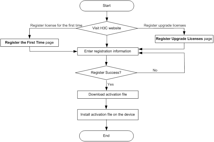
Registering licenses
Registering licenses for the first time
1. Visit the H3C website at www.h3c.com. Select Technical Support & Documents > Register the First Time.
Figure 56 Registering a license for the first time
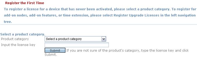
2. Select Router_H3C MSR26, Router_H3C MSR36, or Router_H3C MSR56 from the Product category dropdown list, and click Submit.
If you do not know the product category, enter the license key in the text box, and the product category is automatically displayed.
Figure 57 Selecting a product category
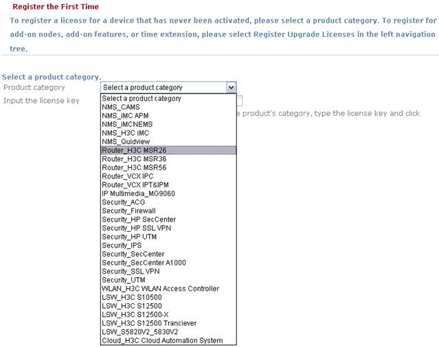
Table 18 describes the configuration items on the page.
Figure 58 Entering the information
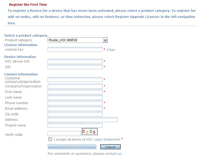
|
Item |
Description |
Remarks |
|
License key |
Enter the license key provided on the paper license. |
Required. |
|
H3C device S/N |
Enter the device serial number, a string of 20 characters. You can use the display license device-id command to display the device serial number. |
Required. |
|
DID |
Enter the device identifier DID. You can use the display license device-id command to display the DID. |
Required. |
|
Customer company/organization |
Enter the name of the company or organization that uses the device. |
Required. |
|
Company/organization |
Enter your company or organization name. |
Required. |
|
First name |
Enter your first name. |
Required. |
|
Last name |
Enter your last name. |
Optional. |
|
Phone number |
Enter your phone number. |
Required. |
|
Email address |
Enter your email address. H3C will send a copy of the activation file to your email box in addition to providing a link to the activation file on the registration result page. |
Required. |
|
Zip code |
Enter the zip code of your region. |
Optional. |
|
Address |
Enter your address. |
Optional. |
|
Project name |
Enter the name of the project that uses the device. |
Optional. |
|
Verify code |
Enter the code literally as is displayed on the image to the right of the text box. |
Required. |
4. When the registration success message is displayed, click the .lic link to save the activation file. Unzip the file and follow the procedures described in "Activating licenses" to activate the licenses on your devices.
Figure 59 Registration success
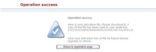
Registering upgrade licenses
1. Visit the H3C website at www.h3c.com, and select Technical Support & Documents > Register Upgrade Licenses.
Figure 60 Registering an upgrade license
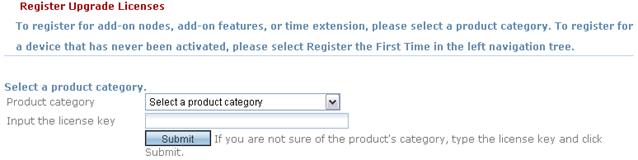
2. Select Router_H3C MSR26, Router_H3C MSR36, or Router_H3C MSR56 from the Product category dropdown list, and click Submit.
If you do not know the product category, enter the license key in the text box, and the product category is automatically displayed.
Figure 61 Selecting a product category
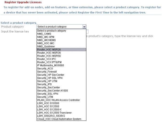
3. Enter the device information and click Submit.
Table 19 describes the configuration items on the page.
Figure 62 Entering the device information
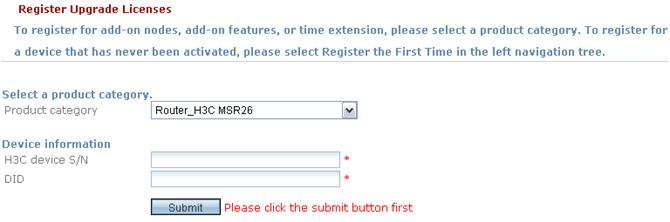
|
Item |
Description |
Remarks |
|
H3C device S/N |
Enter the device serial number, a string of 20 characters. You can use the display license device-id command to display the device serial number. |
Required. |
|
DID |
Enter the device identifier DID. You can use the display license device-id command to display the DID. |
Required. |
Figure 63 Typing the information for license upgrade
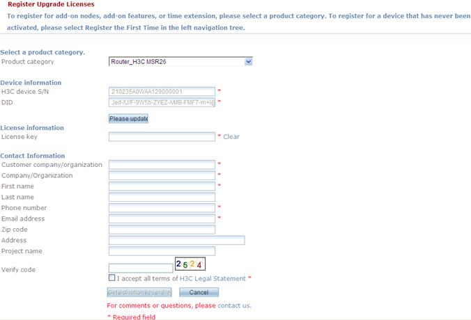
|
Item |
Description |
Remarks |
|
License key |
Enter the license key provided on the paper license. |
Required. |
|
Customer company/organization |
Enter the name of the company or organization that uses the device. |
Required. |
|
Company/organization |
Enter your company or organization name. |
Required. |
|
First name |
Enter your first name. |
Required. |
|
Last name |
Enter your last name. |
Optional. |
|
Phone number |
Enter your phone number. |
Required. |
|
Email address |
Enter your email address. H3C will send a copy of the activation file to your email box in addition to providing a link to the activation file on the registration result page. |
Required. |
|
Zip code |
Enter the zip code of your region. |
Optional. |
|
Address |
Enter your address. |
Optional. |
|
Project name |
Enter the name of the project that uses the device. |
Optional. |
|
Verify code |
Enter the code literally as is displayed on the image to the right of the text box. |
Required. |
5. When the registration success message is displayed, click the .lic link to save the activation file.
Unzip the file and follow the procedures described in "Activating licenses" to activate the license on your device.
Figure 64 Registration success

Activating licenses
Follow these steps to activate a license on your device:
1. Upload the activation file to the storage media of the device through FTP or TFTP.
2. Use the license activation-file install command in system view to install the activation file.
<H3C> system-view
[H3C] license activation-file install cfa0:/ 210235A0W8B1330000412013073110284693735.ak
3. Verify that the license is in use.
Execute the display license command in user view. Check the Current State field. If the state is In use, the license is activated successfully and being used.
<H3C> display license
cfa0:/license/210235A0W8B1330000412013073110284693735.ak
Feature: pkg_license
Product Description: H3C MSR56 Data Software License
Registered at: 2017-03-03 03:56:53
License Type: Trial (days restricted)
Trial Time Left (days): 30
Current State: In use
Accessing the CLI online help,2
Activating licenses,267
Assigning user roles,25
Backing up the main next-startup configuration file to a TFTP server,114
CLI overview,46
CLI views,1
Command and hardware compatibility,90
Command and hardware compatibility,119
Command and hardware compatibility,160
Command and hardware compatibility,95
Command and hardware compatibility,106
Command and hardware compatibility,72
Command and hardware compatibility,220
Comparing configurations for their differences,107
Compatibility information,246
Compatibility information,188
Comware 7 extended Python API functions,249
Configuration task list,20
Configuring a feature group,23
Configuring a security zone,215
Configuring banners,222
Configuring command accounting,69
Configuring command authorization,66
Configuring configuration rollback,109
Configuring local console or AUX login,47
Configuring resource access policies,23
Configuring SSH login,57
Configuring Telnet login,52
Configuring temporary user role authorization,27
Configuring the device as an IPv4 TFTP client,90
Configuring the device as an IPv6 TFTP client,91
Configuring the device name,221
Configuring the system time,221
Configuring user role rules,21
Controlling SNMP access,63
Controlling Telnet and SSH logins,62
Controlling the CLI output,10
Creating a user role,20
Deleting a next-startup configuration file,115
Device management task list,220
Disabling all USB interfaces,237
Disabling password recovery capability,231
Displaying and maintaining CLI login,59
Displaying and maintaining configuration files,115
Displaying and maintaining device management configuration,240
Displaying and maintaining ISSU,169
Displaying and maintaining RBAC settings,29
Displaying and maintaining software image settings,136
Displaying device information in emergency shell mode,192
Displaying security zones,217
Emergency shell usage example,193
Enabling configuration encryption,106
Enabling displaying the copyright statement,222
Enabling software synchronization from the active MPU to the standby MPU at startup,134
Entering a command,3
Entering the Python shell,247
Examples of using install commands for ISSU (centralized devices in IRF mode),177
Examples of using install commands for ISSU (centralized devices in standalone mode),172
Examples of using install commands for ISSU (distributed devices in IRF mode),181
Examples of using install commands for ISSU (distributed devices in standalone mode),174
Executing a Python script,247
Executing Comware commands in Tcl configuration view,245
Feature and hardware compatibility,196
Feature and hardware compatibility,44
Feature and hardware compatibility,260
Feature and hardware compatibility,214
File system management restrictions and guidelines,96
FIPS compliance,106
FIPS compliance,90
FIPS compliance,20
FIPS compliance,95
FIPS compliance,73
FIPS compliance,44
Importing and using the Comware 7 extended Python API,249
Licensing procedure summary,261
Loading the system image,192
Login methods,43
Managing directories,97
Managing files,99
Managing power supply,231
Managing storage media and file systems,96
Managing the file systems,189
Monitoring CPU usage,233
Obtaining a system image from an FTP/TFTP server,190
Overview,196
Overview,159
Overview,256
Overview,246
Overview,17
Overview,117
Overview,72
Overview,92
Overview,213
Overview,104
Overview,188
Performing an ISSU by using install commands,163
Performing an upgrade by using install commands,127
Preloading the Boot ROM image,121
Preparing for ISSU,160
Preparing for the upgrade,120
Python usage example,247
RBAC configuration examples,29
Rebooting the device,224
Rebooting the device,192
Registering licenses,261
Restoring the factory-default configuration,239
Restoring the main next-startup configuration file from a TFTP server,114
Restrictions and guidelines,215
Saving the running configuration,16
Saving the running configuration,107
Scheduling a task,225
Security zone configuration example,217
Security zone configuration task list,215
Server-based automatic configuration examples,205
Setting memory alarm thresholds,235
Setting the operating mode for an interface card,237
Setting the port status detection timer,233
Software upgrade examples by using install commands (centralized devices in IRF mode),149
Software upgrade examples by using install commands (centralized devices in standalone mode),143
Software upgrade examples by using install commands (distributed devices in IRF mode),152
Software upgrade examples by using install commands (distributed devices in standalone mode),145
Software upgrade examples by using the boot-loader file command,139
Software upgrade task list,121
Specifying a next-startup configuration file,113
Specifying startup images and completing the upgrade,122
Synchronizing files and directories from an Rsync server,103
Troubleshooting RBAC,41
Understanding command-line error messages,8
Unmounting HMIM modules,239
Updating the modem firmware through FoTA,240
Upgrade methods,119
Upgrade restrictions and guidelines,120
Upgrading firmware,135
Using server-based automatic configuration,197
Using SMS-based automatic configuration,203
Using Tcl to configure the device,244
Using the automatic copying feature,102
Using the command history feature,9
Using the device as an FTP client,80
Using the device as an FTP server,73
Using the undo form of a command,3
Using USB-based automatic configuration,202
Verifying and diagnosing transceiver modules,238