- Table of Contents
-
- 11-Network Management and Monitoring Configuration Guide
- 00-Preface
- 01-System maintenance and debugging configuration
- 02-NQA configuration
- 03-NTP configuration
- 04-PTP configuration
- 05-SNMP configuration
- 06-RMON configuration
- 07-Event MIB configuration
- 08-NETCONF configuration
- 09-Puppet configuration
- 10-Chef configuration
- 11-CWMP configuration
- 12-EAA configuration
- 13-Process monitoring and maintenance configuration
- 14-Sampler configuration
- 15-Mirroring configuration
- 16-NetStream configuration
- 17-IPv6 NetStream configuration
- 18-sFlow configuration
- 19-Information center configuration
- 20-GOLD configuration
- 21-Packet capture configuration
- 22-VCF fabric configuration
- 23-Ansible configuration
- Related Documents
-
| Title | Size | Download |
|---|---|---|
| 04-PTP configuration | 341.58 KB |
Grandmaster clock selection and master-member/subordinate relationship establishment
Restrictions and guidelines: PTP configuration
Configuring PTP (IEEE 1588 version 2)
Configuring PTP (IEEE 802.1AS)
Configuring PTP (SMPTE ST 2059-2)
Specifying PTP for obtaining the time
Configuring an OC to operate only as a member clock
Configuring the role of a PTP port
Configuring the mode for carrying timestamps
Specifying a delay measurement mechanism for a BC or an OC
Configuring one of the ports on a TC+OC clock as an OC-type port
Configuring PTP message transmission and receipt
Setting the interval for sending Pdelay_Req messages
Setting the interval for sending Sync messages
Setting the minimum interval for sending Delay_Req messages
Configuring parameters for PTP messages
Specifying the protocol for encapsulating PTP messages as UDP
Configuring a source IP address for multicast PTP message transmission over UDP
Configuring a destination IP address for unicast PTP message transmission over UDP
Configuring the MAC address for non-Pdelay messages
Setting a DSCP value for PTP messages transmitted over UDP
Specifying a VLAN tag for PTP messages
Adjusting and correcting clock synchronization
Setting the delay correction value
Setting the cumulative offset between the UTC and TAI
Setting the correction date of the UTC
Configuring ToD input or output
Configuring a priority for a clock
Display and maintenance commands for PTP
Example: Configuring PTP configuration (IEEE 1588 version 2, IEEE 802.3/Ethernet encapsulation)
Example: Configuring PTP (IEEE 1588 version 2, multicast transmission)
Example: Configuring PTP configuration (IEEE 1588 version 2, unicast transmission)
Example: Configuring PTP (IEEE 802.1AS)
Example: Configuring PTP (SMPTE ST 2059-2, multicast transmission)
Example: Configuring PTP (SMPTE ST 2059-2, unicast transmission)
Configuring PTP
About PTP
Precision Time Protocol (PTP) provides time synchronization among devices with submicrosecond accuracy. It provides also precise frequency synchronization.
Basic concepts
PTP profile
PTP profiles (PTP standards) include:
· IEEE 1588 version 2—1588v2 defines high-accuracy clock synchronization mechanisms. It can be customized, enhanced, or tailored as needed. 1588v2 is the latest version.
· IEEE 802.1AS—802.1AS is introduced based on IEEE 1588. It specifies a profile for use of IEEE 1588-2008 for time synchronization over a virtual bridged local area network (as defined by IEEE 802.1Q). 802.1AS supports point-to-point full-duplex Ethernet, IEEE 802.11, and IEEE 802.3 EPON links.
· SMPTE ST 2059-2—ST2059-2 is introduced based on IEEE 1588. It specifies a profile specifically for the synchronization of audio or video equipment in a professional broadcast environment. It includes a self-contained description of parameters, their default values, and permitted ranges.
PTP domain
A PTP domain refers to a network that is enabled with PTP. A PTP domain has only one reference clock called "grandmaster clock (GM)." All devices in the domain synchronize to the clock.
Clock node and PTP port
A node in a PTP domain is a clock node. A port enabled with PTP is a PTP port. PTP defines the following types of basic clock nodes:
· Ordinary Clock (OC)—A PTP clock with a single PTP port in a PTP domain for time synchronization. It synchronizes time from its upstream clock node through the port. If an OC operates as the clock source, it sends synchronization time through a single PTP port to its downstream clock nodes.
· Boundary Clock (BC)—A clock with more than one PTP port in a PTP domain for time synchronization. A BC uses one of the ports to synchronize time from its upstream clock node. It uses the other ports to synchronize time to the relevant upstream clock nodes. If a BC operates as the clock source, such as BC 1 in Figure 1, it synchronizes time through multiple PTP ports to its downstream clock nodes.
· Transparent Clock (TC)—A TC does not keep time consistency with other clock nodes. A TC has multiple PTP ports. It forwards PTP messages among these ports and performs delay corrections for the messages, instead of performing time synchronization. TCs include the following types:
¡ End-to-End Transparent Clock (E2ETC)—Forwards non-P2P PTP packets in the network and calculates the delay of the entire link.
¡ Peer-to-Peer Transparent Clock (P2PTC)—Forwards only Sync, Follow_Up, and Announce messages, terminates other PTP messages, and calculates the delay of each link segment.
Figure 1 shows the positions of these types of clock nodes in a PTP domain.
Figure 1 Clock nodes in a PTP domain
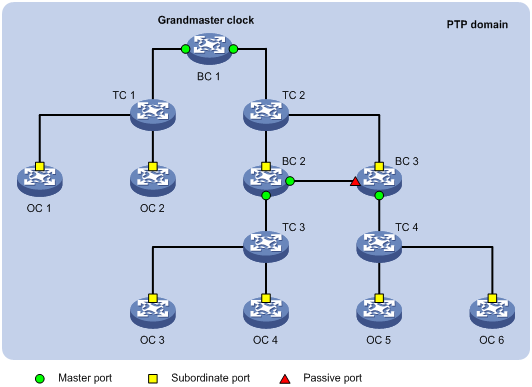
In addition to these basic types of clock nodes, PTP introduces hybrid clock nodes. For example, a TC+OC has multiple PTP ports in a PTP domain. One port is the OC type, and the others are the TC type.
A TC+OC forwards PTP messages through TC-type ports and performs delay corrections. In addition, it synchronizes time through its OC-type port. TC+OCs include these types: E2ETC+OC and P2PTC+OC.
Master-member/subordinate relationship
The master-member/subordinate relationship is automatically determined based on the Best Master Clock (BMC) algorithm. You can also manually specify a role for the clock nodes.
The master-member/subordinate relationship is defined as follows:
· Master/Member node—A master node sends a synchronization message, and a member node receives the synchronization message.
· Master/Member clock—The clock on a master node is a master clock (parent clock) The clock on a member node is a member clock.
· Master/Subordinate port—A master port sends a synchronization message, and a subordinate port receives the synchronization message. The master and subordinate ports can be on a BC or an OC.
A port that neither receives nor sends synchronization messages is a passive port.
Grandmaster clock
As shown in Figure 1, the clock nodes in a PTP domain are organized into a master-member hierarchy, where the GM operates as the reference clock for the entire PTP domain. Time synchronization is implemented through exchanging PTP messages.
Clock type
A clock node of a device can use one of the following clocks:
· Local clock—38.88 MHz clock signals generated by a crystal oscillator inside the clock monitoring module. You cannot configure time class and accuracy for a local clock.
· ToD clock—Clock signals generated by a ToD clock. The signals are sent and received by ToD interfaces (ToD 0 and ToD 1) on the master device. The device sends the received signals to the clock monitoring module, which then sends them to all subordinate devices on the device. You can configure time class and accuracy for a ToD clock.
The clock node determines which type of clock source to use.
Grandmaster clock selection and master-member/subordinate relationship establishment
A GM can be manually specified. It can also be elected through the BMC algorithm as follows:
1. The clock nodes in a PTP domain exchange announce messages and elect a GM by using the following rules in descending order:
a. Clock node with higher priority 1.
b. Clock node with higher time class.
c. Clock node with higher time accuracy.
d. Clock node with higher priority 2.
e. Clock node with a smaller port ID (containing clock number and port number).
The master nodes, member nodes, master ports, and subordinate ports are determined during the process. Then a spanning tree with the GM as the root is generated for the PTP domain.
2. The master node periodically sends announce messages to the member nodes. If the member nodes do not receive announce messages from the master node, they determine that the master node is invalid, and they start to elect another GM.
Synchronization mechanism
After the master-member relationship is established between the clock nodes, PTP sends synchronization messages between the master and member nodes to determine the delay measurement. The one-way delay time is the average of the delay of the transmit and receive messages. The member nodes use this delay time to adjust their local clocks.
PTP defines the following transmission delay measurement mechanisms:
· Request_Response.
· Peer Delay.
Both mechanisms assume a symmetric communication path.
Request_Response
The Request_Response mechanism includes the following modes:
· Single-step mode—t1 is carried in the Sync message, and no Follow_Up message is sent.
This mode is not supported in the current software version.
· Two-step mode—t1 is carried in the Follow_Up message.
Figure 2 Operation procedure of the Request_Response mechanism
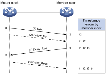
Figure 2 shows an example of the Request_Response mechanism in two-step mode.
1. The master clock sends a Sync message to the member clock, and records the sending time t1. Upon receiving the message, the member clock records the receiving time t2.
2. After sending the Sync message, the master clock immediately sends a Follow_Up message that carries time t1.
3. The member clock sends a Delay_Req message to calculate the transmission delay in the reverse direction, and records the sending time t3. Upon receiving the message, the master clock records the receiving time t4.
4. The master clock returns a Delay_Resp message that carries time t4.
After this procedure, the member clock collects all four timestamps and obtains the round-trip delay to the master clock by using the following calculation:
· [(t2 – t1) + (t4 – t3)]
The member clock also obtains the one-way delay by using the following calculation:
· [(t2 – t1) + (t4 – t3)] / 2
The offset between the member and master clocks is obtained by using the following calculations:
· (t2 – t1) – [(t2 – t1) + (t4 – t3)] / 2
· [(t2 – t1) – (t4 – t3)] / 2
Peer Delay
The Peer Delay mechanism includes the following modes:
· Single-step mode:
¡ t1 is carried in the Sync message, and no Follow_Up message is sent.
¡ The offset between t5 and t4 is carried in the Pdelay_Resp message, and no Pdelay_Resp_Follow_Up message is sent.
This mode is not supported in the current software version.
· Two-step mode:
¡ t1 is carried in the Follow_Up message.
¡ t4 and t5 are carried in the Pdelay_Resp and Pdelay_Resp_Follow_Up messages.
Figure 3 Operation procedure of the Peer Delay mechanism
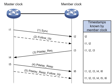
The Peer Delay mechanism uses Pdelay messages to calculate link delay, which applies only to point-to-point delay measurement. Figure 3 shows an example of the Peer Delay mechanism by using the two-step mode.
1. The master clock sends a Sync message to the member clock, and records the sending time t1. Upon receiving the message, the member clock records the receiving time t2.
2. After sending the Sync message, the master clock immediately sends a Follow_Up message that carries time t1.
3. The member clock sends a Pdelay_Req message to calculate the transmission delay in the reverse direction, and records the sending time t3. Upon receiving the message, the master clock records the receiving time t4.
4. The master clock returns a Pdelay_Resp message that carries time t4, and records the sending time t5. Upon receiving the message, the member clock records the receiving time t6.
5. After sending the Pdelay_Resp message, the master clock immediately sends a Pdelay_Resp_Follow_Up message that carries time t5.
After this procedure, the member clock collects all six timestamps and obtains the round-trip delay to the master clock by using the following calculation:
· [(t4 – t3) + (t6 – t5)]
The member clock also obtains the one-way delay by using the following calculation:
· [(t4 – t3) + (t6 – t5)] / 2
The offset between the member and master clocks is as follows:
· (t2 – t1) – [(t4 – t3) + (t6 – t5)] / 2
Protocols and standards
· IEEE 1588-2008, IEEE Standard for a Precision Clock Synchronization Protocol for Networked Measurement and Control Systems
· IEEE P802.1AS, Timing and Synchronization for Time-Sensitive Applications in Bridged Local Area Networks
Restrictions and guidelines: PTP configuration
Before configuring PTP, determine the PTP profile and define the scope of the PTP domain and the role of every clock node.
PTP tasks at a glance
Configuring PTP (IEEE 1588 version 2)
1. Specifying PTP for obtaining the time
Specify the IEEE 1588 version 2 PTP profile.
¡ Specifying a clock node type
¡ (Optional.) Configuring an OC to operate only as a member clock
4. (Optional.) Specifying a PTP domain
¡ (Optional.) Configuring the role of a PTP port
¡ Configuring the mode for carrying timestamps
¡ Specifying a delay measurement mechanism for a BC or an OC
¡ Configuring one of the ports on a TC+OC clock as an OC-type port
7. (Optional.) Configuring PTP message transmission and receipt
¡ Setting the interval for sending Pdelay_Req messages
¡ Setting the interval for sending Sync messages
¡ Setting the minimum interval for sending Delay_Req messages
8. (Optional.) Configuring parameters for PTP messages
¡ Specifying the protocol for encapsulating PTP messages as UDP
¡ Configuring a source IP address for multicast PTP message transmission over UDP
¡ Configuring a destination IP address for unicast PTP message transmission over UDPConfiguring a destination IP address for
¡ Configuring the MAC address for non-Pdelay messages
¡ Setting a DSCP value for PTP messages transmitted over UDP
¡ Specifying a VLAN tag for PTP messages
9. (Optional.) Adjusting and correcting clock synchronization
¡ Setting the delay correction value
¡ Setting the cumulative offset between the UTC and TAI
¡ Setting the correction date of the UTC
¡ Configuring ToD input or output
10. (Optional.) Setting ToD clock parameters
11. (Optional.) Configuring a priority for a clock
Configuring PTP (IEEE 802.1AS)
1. Specifying PTP for obtaining the time
Specify the IEEE 802.1AS PTP profile.
¡ Specifying a clock node type
¡ (Optional.) Configuring an OC to operate only as a member clock
4. (Optional.) Specifying a PTP domain
¡ (Optional.) Configuring the role of a PTP port
¡ Configuring one of the ports on a TC+OC clock as an OC-type port
7. (Optional.) Configuring PTP message transmission and receipt
¡ Setting the interval for sending Pdelay_Req messages
¡ Setting the interval for sending Sync messages
8. (Optional.) Specifying a VLAN tag for PTP messages
9. (Optional. ) Adjusting and correcting clock synchronization
¡ Setting the delay correction value
¡ Setting the cumulative offset between the UTC and TAI
¡ Setting the correction date of the UTC
¡ Configuring ToD input or output
10. (Optional.) Setting ToD clock parameters
11. (Optional.) Configuring a priority for a clock
Configuring PTP (SMPTE ST 2059-2)
1. Specifying PTP for obtaining the time
Specify the SMPTE ST 2059-2 PTP profile.
¡ Specifying a clock node type
¡ (Optional.) Configuring an OC to operate only as a member clock
4. (Optional.) Specifying a PTP domain
¡ (Optional.) Configuring the role of a PTP port
¡ Configuring the mode for carrying timestamps
¡ Specifying a delay measurement mechanism for a BC or an OC
7. (Optional.) Configuring PTP message transmission and receipt
¡ Setting the interval for sending Pdelay_Req messages
¡ Setting the interval for sending Sync messages
¡ Setting the minimum interval for sending Delay_Req messages
8. (Optional.) Configuring parameters for PTP messages
¡ Configuring a source IP address for multicast PTP message transmission over UDP
¡ Configuring a destination IP address for unicast PTP message transmission over UDP
¡ Setting a DSCP value for PTP messages transmitted over UDP
¡ Specifying a VLAN tag for PTP messages
9. (Optional.) Adjusting and correcting clock synchronization
¡ Setting the delay correction value
¡ Setting the cumulative offset between the UTC and TAI
¡ Setting the correction date of the UTC
¡ Configuring ToD input or output
10. (Optional.) Setting ToD clock parameters
11. (Optional.) Configuring a priority for a clock
Specifying PTP for obtaining the time
1. Enter system view.
system-view
2. Specify PTP for obtaining the time.
clock protocol ptp
By default, the device uses NTP to synchronize the system time.
For more information about the clock protocol command, see device management commands in Fundamentals Command Reference.
Specifying a PTP profile
Restrictions and guidelines
You must specify a PTP profile before configuring PTP settings. Changing the PTP profile clears all settings under the profile.
Procedure
1. Enter system view.
system-view
2. Specify a PTP profile.
ptp profile { 1588v2 | 8021as | st2059-2 }
By default, no PTP profile is configured, and PTP is not running on the device.
Configuring clock nodes
Specifying a clock node type
Restrictions and guidelines
You can specify only one clock node type for the device. The clock node types include OC, BC, E2ETC, P2PTC, E2ETC+OC, and P2PTC+OC.
Before you specify a clock node type, specify a PTP profile.
For the IEEE 802.1AS PTP profile, you cannot specify the E2ETC or E2ETC+OC clock node type.
For the SMPTE ST 2059-2 PTP profile, you cannot specify the E2ETC+OC or P2PTC+OC clock node type.
Changing or removing the clock node type restores the default settings of the PTP profile.
Procedure
1. Enter system view.
system-view
2. Specify a clock node type for the device.
ptp mode { bc | e2etc | e2etc-oc | oc | p2ptc | p2ptc-oc }
By default, no clock node type is specified.
Configuring an OC to operate only as a member clock
About configuring an OC to operate only as a member clock
An OC can operate either as a master clock to send synchronization messages or as a member clock to receive synchronization messages. This task allows you to configure an OC to operate only as a member clock.
If an OC is operating only as a member clock, you can use the ptp force-state command to configure its PTP port as a master port or passive port.
Restrictions and guidelines
This task is applicable only to OCs.
Procedure
1. Enter system view.
system-view
2. Configure the OC to operate only as a member clock.
ptp slave-only
By default, an OC operates as a master or member clock.
Specifying a PTP domain
About PTP domains
Within a PTP domain, all devices follow the same rules to communicate with each other. Devices in different PTP domains cannot exchange PTP messages.
Procedure
1. Enter system view.
system-view
2. Specify a PTP domain for the device.
ptp domain value
By default, the device is in PTP domain 0 for the IEEE 1588 version 2 or IEEE 802.1AS PTP profile, and is in PTP domain 127 for the SMPTE ST 2059-2 PTP profile.
Enabling PTP on a port
About enabling PTP on a port
A port enabled with PTP becomes a PTP port.
Restrictions and guidelines
You can enable PTP on only one port on an OC.
Procedure
1. Enter system view.
system-view
2. Enter Layer 2 Ethernet interface view or Layer 3 Ethernet interface view.
interface interface-type interface-number
3. Enable PTP on the port.
ptp enable
By default, PTP is disabled on a port.
Configuring PTP ports
Configuring the role of a PTP port
About configuring the role of a PTP port
You can configure the master, passive, or slave role for a PTP port.
For an OC that operates in slave-only mode, you can perform this task to change its PTP port role to master or slave.
Restrictions and guidelines
Only one subordinate port is allowed to be configured for a device.
Procedure
1. Enter system view.
system-view
2. Enter Layer 2 Ethernet interface view or Layer 3 Ethernet interface view.
interface interface-type interface-number
3. Configure the role of the PTP port.
ptp force-state { master | passive | slave }
By default, the PTP port role is automatically calculated through BMC.
4. Return to system view.
quit
5. Activate the port role configuration.
ptp active force-state
By default, the port role configuration is not activated.
Configuring the mode for carrying timestamps
About the mode for carrying timestamps
Timestamps can be carried in either of the following modes:
· Single-step mode—The following messages contain the message sending time:
¡ Sync message in the Request_Response and Peer Delay mechanisms.
¡ Pdelay_Resp message in the Peer Delay mechanism.
This mode is not supported in the current software version.
· Two-step mode—All messages contain the message sending time, except for the following messages:
¡ Sync message in the Request_Response and Peer Delay mechanisms.
¡ Pdelay_Resp message in the Peer Delay mechanism.
Procedure
1. Enter system view.
system-view
2. Enter Layer 2 Ethernet interface view or Layer 3 Ethernet interface view.
interface interface-type interface-number
3. Configure the mode for carrying timestamps.
ptp clock-step { one-step | two-step }
The one-step keyword is not supported in the current software version.
Specifying a delay measurement mechanism for a BC or an OC
About the delay measurement mechanism
PTP defines two transmission delay measurement mechanisms: Request_Response and Peer Delay. For correct communication, ports on the same link must share the same delay measurement mechanism.
The delay measurement mechanism is Request_Response for E2ETCs and E2ETC+OCs and Peer Delay for P2PTCs and P2PTC+OCs. You cannot change the delay measurement mechanism for these clock nodes
Restrictions and guidelines
This task is applicable only to BCs and OCs.
The IEEE 802.1AS PTP profile supports only the peer delay measurement mechanism. This task is not available for the IEEE 802.1AS PTP profile.
Procedure
1. Enter system view.
system-view
2. Enter Layer 2 Ethernet interface view or Layer 3 Ethernet interface view.
interface interface-type interface-number
3. Specify a delay measurement mechanism for a BC or an OC.
ptp delay-mechanism { e2e | p2p }
The default delay measurement mechanism depends on the PTP profile.
Configuring one of the ports on a TC+OC clock as an OC-type port
About configuring one of the ports on a TC+OC clock as an OC-type port
All ports on a TC+OC (E2ETC+OC or P2PTC+OC) are TC-type ports by default. This feature allows you to configure one of the ports on a TC+OC clock as an OC-type port.
Restrictions and guidelines
This task is applicable only to E2ETC+OCs and P2PTC+OCs.
This task is not available for the SMPTE ST 2059-2 PTP profile.
When a TC+OC is synchronizing time to a downstream clock node through a TC-type port, prevent it from synchronizing with the downstream clock node through an OC-type port.
Procedure
1. Enter system view.
system-view
2. Enter Layer 2 Ethernet interface view or Layer 3 Ethernet interface view.
interface interface-type interface-number
3. Configure the port type as OC.
ptp port-mode oc
By default, the port type for all ports on a TC+OC is TC.
Configuring PTP message transmission and receipt
Setting the interval for sending announce messages and the timeout multiplier for receiving announce messages
About the interval for sending announce messages and the timeout multiplier for receiving announce messages
A master node sends announce messages to the member nodes at the specified interval. If a member node does not receive any announce messages from the master node within the specified interval, it determines that the master node is invalid.
For the IEEE 1588 version 2 or SMPTE ST 2059-2 PTP profile, the timeout for receiving announce messages is the announce message sending interval for the subordinate node × multiple-value. For IEEE 802.1AS, the timeout for receiving announce messages is the announce message sending interval for the master node × multiple-value.
Procedure
1. Enter system view.
system-view
2. Enter Layer 2 Ethernet interface view or Layer 3 Ethernet interface view.
interface interface-type interface-number
3. Set the interval for sending announce messages.
ptp announce-interval interval
The default settings vary by PTP profile.
¡ IEEE 1588 version 2—The interval argument value is 1 and the interval for sending announce messages is 2 (21) seconds.
¡ IEEE 802.1AS—The interval argument value is 0 and the interval for sending announce messages is 1 (20)second.
¡ SMPTE ST 2059-2—The interval argument value is –2 and the interval for sending announce messages is 1/4 (2-2) seconds.
4. Set the number of intervals before a timeout occurs.
ptp announce-timeout multiple-value
By default, a timeout occurs when three intervals are reached.
Setting the interval for sending Pdelay_Req messages
1. Enter system view.
system-view
2. Enter Layer 2 Ethernet interface view or Layer 3 Ethernet interface view.
interface interface-type interface-number
3. Set the interval for sending Pdelay_Req messages.
ptp pdelay-req-interval interval
By default, the interval argument value is 0 and the interval for sending peer delay request messages is 1 (20) second.
For the SMPTE ST 2059-2 PTP profile, set the interval argument to a value in the range of ptp syn-interval interval to ptp syn-interval interval plus 5 as a best practice.
Setting the interval for sending Sync messages
1. Enter system view.
system-view
2. Enter Layer 2 Ethernet interface view or Layer 3 Ethernet interface view.
interface interface-type interface-number
3. Set the interval for sending Sync messages.
ptp syn-interval interval
The default settings vary by PTP profile.
¡ IEEE 1588 version 2—The interval argument value is 0 and the interval for sending Sync messages is 1 (20) second.
¡ IEEE 802.1AS or SMPTE ST 2059-2—The interval argument value is –3 and the interval for sending Sync messages is 1/8 (2-3) seconds.
Setting the minimum interval for sending Delay_Req messages
About the minimum interval for sending Delay_Req messages
When receiving a Sync or Follow_Up message, an interface can send Delay_Req messages only when the minimum interval is reached.
Restrictions and guidelines
This task is not available for the IEEE 802.1AS PTP profile.
The interval takes effect only if it is set on the master clock. The master clock sends the value to a member clock through PTP messages to control the interval for the member clock to send Delay_Req messages. To view the interval, execute the display ptp interface command on the member clock.
Procedure
1. Enter system view.
system-view
2. Enter Layer 2 Ethernet interface view or Layer 3 Ethernet interface view.
interface interface-type interface-number
3. Set the minimum interval for sending Delay_Req messages.
ptp min-delayreq-interval interval
The interval argument value is 0 and the minimum interval for sending delay request messages is 1 (20) second.
For the SMPTE ST 2059-2 PTP profile, set the interval argument to a value in the range of ptp syn-interval interval to ptp syn-interval interval plus 5 as a best practice.
Configuring parameters for PTP messages
Specifying the protocol for encapsulating PTP messages as UDP
About PTP message encapsulation protocols
PTP messages can be encapsulated in IEEE 802.3/Ethernet packets or UDP packets.
Restrictions and guidelines
For the IEEE 802.1AS PTP profile, PTP messages can be encapsulated only in IEEE 802.3/Ethernet packets.
For the SMPTE ST 2059-2 PTP profile, PTP messages can be encapsulated only in UDP packets.
This task is not available for the IEEE 802.1AS or SMPTE ST 2059-2 PTP profile.
Procedure
1. Enter system view.
system-view
2. Enter Layer 2 Ethernet interface view or Layer 3 Ethernet interface view.
interface interface-type interface-number
3. Configure the protocol for encapsulating PTP messages as UDP.
ptp transport-protocol udp
By default, PTP messages are encapsulated in IEEE 802.3/Ethernet packets.
Configuring a source IP address for multicast PTP message transmission over UDP
About configuring a source IP address for multicast PTP message transmission over UDP
To transport multicast PTP messages over UDP, you must configure a source IP address for the messages.
Restrictions and guidelines
If both a source IP address for multicast PTP message transmission over UDP and a destination address for unicast PTP message transmission over UDP are configured, the system unicasts the messages.
This task is not available for the IEEE 802.1AS PTP profile.
Procedure
1. Enter system view.
system-view
2. Configure a source IP address for multicast PTP message transmission over UDP.
ptp source ip-address [ vpn-instance vpn-instance-name ]
By default, no source IP address is configured for multicast PTP message transmission over UDP.
Configuring a destination IP address for unicast PTP message transmission over UDP
About configuring a destination IP address for unicast PTP message transmission over UDP
To transport unicast PTP messages over UDP, you must configure a destination IP address for the messages.
Restrictions and guidelines
If both a source IP address for multicast PTP message transmission over UDP and a destination address for unicast PTP message transmission over UDP are configured, the system unicasts the messages.
This task is not available for the IEEE 802.1AS PTP profile.
Prerequisites
Configure an IP address for the current interface, and make sure the interface and the peer PTP interface can reach each other.
Procedure
1. Enter system view.
system-view
2. Enter Layer 3 Ethernet interface view.
interface interface-type interface-number
3. Configure a destination IP address for unicast PTP message transmission over UDP.
ptp unicast-destination ip-address
By default, no destination IP address is configured for unicast PTP message transmission over UDP.
Configuring the MAC address for non-Pdelay messages
About the MAC address for non-Pdelay messages
Pdelay messages include Pdelay_Req, Pdelay_Resp, and Pdelay_Resp_Follow_Up messages. The destination MAC address of Pdelay messages is 0180-C200-000E by default, which cannot be modified. The destination MAC address of non-Pdelay messages is either 0180-C200-000E or 011B-1900-0000.
Restrictions and guidelines
This feature takes effect only when PTP messages are encapsulated in IEEE 802.3/Ethernet packets.
This task is not available for the IEEE 802.1AS or SMPTE ST 2059-2 PTP profile.
Procedure
1. Enter system view.
system-view
2. Enter Layer 2 Ethernet interface view or Layer 3 Ethernet interface view.
interface interface-type interface-number
3. Configure the destination MAC address for non-Pdelay messages.
ptp destination-mac mac-address
The default destination MAC address is 011B-1900-0000.
Setting a DSCP value for PTP messages transmitted over UDP
About DSCP values for PTP messages
The DSCP value determines the sending precedence of PTP messages transmitted over UDP.
Restrictions and guidelines
This task is not available for the IEEE 802.1AS PTP profile.
Procedure
1. Enter system view.
system-view
2. Enter Layer 2 Ethernet interface view or Layer 3 Ethernet interface view.
interface interface-type interface-number
3. Set a DSCP value for PTP messages transmitted over UDP.
ptp dscp dscp
By default, the DSCP value is 56.
Specifying a VLAN tag for PTP messages
About specifying a VLAN tag for PTP messages
Perform this task to configure the VLAN ID and the 802.1p precedence in the VLAN tag carried by PTP messages.
Procedure
1. Enter system view.
system-view
2. Enter Layer 2 Ethernet interface view.
interface interface-type interface-number
3. Specify a VLAN tag for PTP messages.
ptp vlan vlan-id [ dot1p dot1p-value ]
By default, PTP messages do not have a VLAN tag.
Adjusting and correcting clock synchronization
Setting the delay correction value
About setting the delay correction value
PTP performs time synchronization based on the assumption that the delays in sending and receiving messages are the same. However, this is not practical. If you know the offset between the delays in sending and receiving messages, you can set the delay correction value for more accurate time synchronization.
Procedure
1. Enter system view.
system-view
2. Enter Layer 2 Ethernet interface view or Layer 3 Ethernet interface view.
interface interface-type interface-number
3. Set a delay correction value.
ptp asymmetry-correction { minus | plus } value
The default is 0 nanoseconds. Delay correction is not performed.
Setting the cumulative offset between the UTC and TAI
About setting the cumulative offset between the UTC and TAI
The time displayed on a device is based on the Coordinated Universal Time (UTC). There is an offset between UTC and TAI (International Atomic Time, in English), which is made public periodically. This task allows you to adjust the offset between the UTC and TAI on the device.
Restrictions and guidelines
This configuration is applicable only to the GM.
Procedure
1. Enter system view.
system-view
2. Set the cumulative offset between the UTC and TAI.
ptp utc offset utc-offset
The default is 0 seconds.
Setting the correction date of the UTC
About setting the correction date of the UTC
This task allows you to adjust the UTC at the last minute (23:59) of the specified date.
Restrictions and guidelines
If you configure the setting multiple times, the most recent configuration takes effect.
This configuration takes effect only on the GM.
Procedure
1. Enter system view.
system-view
2. Set the correction date of the UTC.
ptp utc { leap59-date | leap61-date } date
By default, the correction date of the UTC is not configured.
Configuring ToD input or output
About configuring ToD input or output
To use a ToD clock, you must configure ToD input or output:
· ToD input—The device obtains clock signals from an external ToD clock and synchronizes ToD to all cards on the device.
· ToD output—The device operates as a ToD clock to synchronize ToD to other devices in the PTP network.
To implement more accurate time synchronization, you can specify a delay correction value.
Procedure
1. Enter system view.
system-view
2. Configure ToD input or output.
ptp { tod0 | tod1 } { input [ delay input-delay-time ] | output [ delay output-delay-time ] }
By default:
¡ The device receives signals from an external ToD clock.
¡ The delay correction value for a ToD clock is 0 nanoseconds.
Setting ToD clock parameters
1. Enter system view.
system-view
2. Set ToD clock parameters.
ptp clock-source { tod0 | tod1 } { accuracy acc-value | class class-value | time-source ts-value }
By default, the time accuracy is 32, the time class is 6, and the attribute value is 32 for a ToD clock.
Configuring a priority for a clock
About configuring a priority for a clock
Priorities for clocks are used to elect the GM. The smaller the priority value, the higher the priority.
Procedure
1. Enter system view.
system-view
2. Configure the priority for the specified clock for GM election through BMC.
ptp priority clock-source { local | tod0 | tod1 } { priority1 priority1 | priority2 priority2 }
The default value varies by PTP profile:
¡ IEEE 1588 version 2—The priority 1 and priority 2 values are both 128.
¡ IEEE 802.1AS PTP profile—The priority 1 value is 246 and the priority 2 value is 248.
Display and maintenance commands for PTP
Execute display commands in any view and the reset command in user view.
|
Task |
Command |
|
Display PTP clock information. |
display ptp clock |
|
Display the delay correction history. |
display ptp corrections |
|
Display information about foreign master nodes. |
display ptp foreign-masters-record [ interface interface-type interface-number ] |
|
Display PTP information on an interface. |
display ptp interface [ interface-type interface-number | brief ] |
|
Display parent node information for the PTP device. |
display ptp parent |
|
Display PTP statistics. |
display ptp statistics [ interface interface-type interface-number ] |
|
Display PTP clock time properties. |
display ptp time-property |
|
Clear PTP statistics. |
reset ptp statistics [ interface interface-type interface-number ] |
PTP configuration examples
Example: Configuring PTP configuration (IEEE 1588 version 2, IEEE 802.3/Ethernet encapsulation)
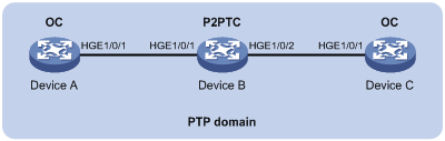
Network configuration
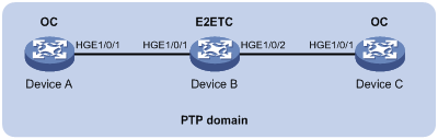
As shown in Figure 4, a PTP domain contains Device A, Device B, and Device C.
· Configure all devices to use the IEEE 1588 version 2 PTP profile.
· Configure PTP messages to be encapsulated in IEEE 802.3/Ethernet packets.
· Specify the OC clock node type for Device A and Device C, and E2ETC clock node type for Device B. All clock nodes elect a GM through BMC based on their respective default GM attributes.
Procedure
1. Configure Device A:
# Specify the IEEE 1588 version 2 PTP profile.
<DeviceA> system-view
[DeviceA] ptp profile 1588v2
# Specify the OC clock node type.
[DeviceA] ptp mode oc
# Specify PTP for obtaining the time.
[DeviceA] clock protocol ptp
# Enable PTP on HundredGigE 1/0/1.
[DeviceA] interface hundredgige 1/0/1
[DeviceA-HundredGigE1/0/1] ptp enable
[DeviceA-HundredGigE1/0/1] quit
2. Configure Device B:
# Specify the IEEE 1588 version 2 PTP profile.
<DeviceB> system-view
[DeviceB] ptp profile 1588v2
# Specify the E2ETC clock node type.
[DeviceB] ptp mode e2etc
# Specify PTP for obtaining the time.
[DeviceB] clock protocol ptp
# Enable PTP on HundredGigE 1/0/1.
[DeviceB] interface hundredgige 1/0/1
[DeviceB-HundredGigE1/0/1] ptp enable
[DeviceB-HundredGigE1/0/1] quit
# Enable PTP on HundredGigE 1/0/2.
[DeviceB] interface hundredgige 1/0/2
[DeviceB-HundredGigE1/0/2] ptp enable
[DeviceB-HundredGigE1/0/2] quit
3. Configure Device C:
# Specify the IEEE 1588 version 2 PTP profile.
<DeviceC> system-view
[DeviceC] ptp profile 1588v2
# Specify the OC clock node type.
[DeviceC] ptp mode oc
# Specify PTP for obtaining the time.
[DeviceC] clock protocol ptp
# Enable PTP on HundredGigE 1/0/1.
[DeviceC] interface hundredgige 1/0/1
[DeviceC-HundredGigE1/0/1] ptp enable
[DeviceC-HundredGigE1/0/1] quit
Verifying the configuration
When the network is stable, perform the following tasks to verify that Device A is elected as the GM, HundredGigE1/0/1 on Device A is the master port, and Device B has synchronized to Device A:
· Use the display ptp clock command to display PTP clock information.
· Use the display ptp interface brief command to display brief PTP statistics on an interface.
# Display PTP clock information on Device A.
[DeviceA] display ptp clock
PTP profile : IEEE 1588 Version 2
PTP mode : OC
Slave only : No
Clock ID : 000FE2-FFFE-FF0000
Clock type : Local
Clock domain : 0
Number of PTP ports : 1
Priority1 : 128
Priority2 : 128
Clock quality :
Class : 248
Accuracy : 254
Offset (log variance) : 65535
Offset from master : 0 (ns)
Mean path delay : 0 (ns)
Steps removed : 0
Local clock time : Sun Jan 15 20:57:29 2011
# Display brief PTP statistics on Device A.
[DeviceA] display ptp interface brief
Name State Delay mechanism Clock step Asymmetry correction
HGE1/0/1 Master E2E Two 0
# Display PTP clock information on Device B.
[DeviceB] display ptp clock
PTP profile : IEEE 1588 Version 2
PTP mode : E2ETC
Slave only : No
Clock ID : 000FE2-FFFE-FF0001
Clock type : Local
Clock domain : 0
Number of PTP ports : 2
Priority1 : 128
Priority2 : 128
Clock quality :
Class : 248
Accuracy : 254
Offset (log variance) : 65535
Offset from master : N/A
Mean path delay : N/A
Steps removed : N/A
Local clock time : Sun Jan 15 20:57:29 2011
# Display brief PTP statistics on Device B.
[DeviceB] display ptp interface brief
Name State Delay mechanism Clock step Asymmetry correction
HGE1/0/1 N/A E2E Two 0
HGE1/0/2 N/A E2E Two 0
Example: Configuring PTP (IEEE 1588 version 2, multicast transmission)
Network configuration
As shown in Figure 5, a PTP domain contains Device A, Device B, and Device C.
· Configure all devices to use the IEEE 1588 version 2 PTP profile.
· Configure the source IP address for multicast PTP message transmission over UDP.
· Specify the OC clock node type for Device A and Device C, and the P2PTC clock node type for Device B. All clock nodes elect a GM through BMC based on their respective default GM attributes.
· Configure the peer delay measurement mechanism (p2p) for Device A and Device C.
Procedure
1. Configure Device A:
# Specify the IEEE 1588 version 2 PTP profile.
<DeviceA> system-view
[DeviceA] ptp profile 1588v2
# Specify the OC clock node type.
[DeviceA] ptp mode oc
# Configure the source IP address for multicast PTP message transmission over UDP.
[DeviceA] ptp source 10.10.10.1
# Specify PTP for obtaining the time.
[DeviceA] clock protocol ptp
# On HundredGigE 1/0/1, specify the PTP transport protocol as UDP, specify the delay measurement mechanism as p2p, and enable PTP.
[DeviceA] interface hundredgige 1/0/1
[DeviceA-HundredGigE1/0/1] ptp transport-protocol udp [DeviceA-HundredGigE1/0/1] ptp delay-mechanism p2p
[DeviceA-HundredGigE1/0/1] ptp enable
[DeviceA-HundredGigE1/0/1] quit
2. Configure Device B:
# Specify the IEEE 1588 version 2 PTP profile.
<DeviceB> system-view
[DeviceB] ptp profile 1588v2
# Specify the P2PTC clock node type.
[DeviceB] ptp mode p2ptc
# Configure the source IP address for multicast PTP message transmission over UDP.
[DeviceB] ptp source 10.10.10.2
# Specify PTP for obtaining the time.
[DeviceB] clock protocol ptp
# On HundredGigE 1/0/1, specify the PTP transport protocol as UDP and enable PTP.
[DeviceB] interface hundredgige 1/0/1
DeviceB-HundredGigE1/0/1] ptp transport-protocol udp
[DeviceB-HundredGigE1/0/1] ptp enable
[DeviceB-HundredGigE1/0/1] quit
# On HundredGigE 1/0/2, specify the PTP transport protocol as UDP and enable PTP.
[DeviceB] interface hundredgige 1/0/2
[DeviceB-HundredGigE1/0/2] ptp transport-protocol udp
[DeviceB-HundredGigE1/0/2] ptp enable
[DeviceB-HundredGigE1/0/2] quit
3. Configure Device C:
# Specify the IEEE 1588 version 2 PTP profile.
<DeviceC> system-view
[DeviceC] ptp profile 1588v2
# Specify the OC clock node type.
[DeviceC] ptp mode oc
# Configure the source IP address for multicast PTP message transmission over UDP.
[DeviceC] ptp source 10.10.10.3
# Specify PTP for obtaining the time.
[DeviceC] clock protocol ptp
# On HundredGigE 1/0/1, specify the PTP transport protocol as UDP, specify the delay measurement mechanism as p2p, and enable PTP.
[DeviceC] interface hundredgige 1/0/1
[DeviceC-HundredGigE1/0/1] ptp transport-protocol udp [DeviceC-HundredGigE1/0/1] ptp delay-mechanism p2p
[DeviceC-HundredGigE1/0/1] ptp enable
[DeviceC-HundredGigE1/0/1] quit
Verifying the configuration
When the network is stable, perform the following tasks to verify that Device A is elected as the GM, HundredGigE1/0/1 on Device A is the master port, and Device B has synchronized to Device A:
· Use the display ptp clock command to display PTP clock information.
· Use the display ptp interface brief command to display brief PTP statistics on an interface.
# Display PTP clock information on Device A.
[DeviceA] display ptp clock
PTP profile : IEEE 1588 Version 2
PTP mode : OC
Slave only : No
Clock ID : 000FE2-FFFE-FF0000
Clock type : Local
Clock domain : 0
Number of PTP ports : 1
Priority1 : 128
Priority2 : 128
Clock quality :
Class : 248
Accuracy : 254
Offset (log variance) : 65535
Offset from master : 0 (ns)
Mean path delay : 0 (ns)
Steps removed : 0
Local clock time : Sun Jan 15 20:57:29 2011
# Display brief PTP statistics on Device A.
[DeviceA] display ptp interface brief
Name State Delay mechanism Clock step Asymmetry correction
HGE1/0/1 Master P2P Two 0
# Display PTP clock information on Device B.
[DeviceB] display ptp clock
PTP profile : IEEE 1588 Version 2
PTP mode : P2PTC
Slave only : No
Clock ID : 000FE2-FFFE-FF0001
Clock type : Local
Clock domain : 0
Number of PTP ports : 2
Priority1 : 128
Priority2 : 128
Clock quality :
Class : 248
Accuracy : 254
Offset (log variance) : 65535
Offset from master : N/A
Mean path delay : N/A
Steps removed : N/A
Local clock time : Sun Jan 15 20:57:29 2011
# Display brief PTP statistics on Device B.
[DeviceB] display ptp interface brief
Name State Delay mechanism Clock step Asymmetry correction
HGE1/0/1 N/A P2P Two 0
HGE1/0/2 N/A P2P Two 0
Example: Configuring PTP configuration (IEEE 1588 version 2, unicast transmission)
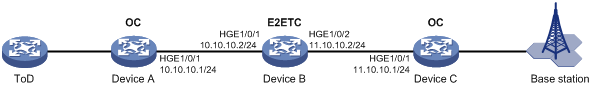
Network configuration
As shown in Figure 6, a PTP domain contains Device A, Device B, and Device C. Device A is the GM and receives the ToD clock signals. Device C sends ToD clock signals to the base station through its ToD interface.
· Configure all devices to use the IEEE 1588 version 2 PTP profile.
· Configure the destination IP address for unicast PTP messages transmission over UDP.
· Specify the OC clock node type for Device A and Device C, and the E2ETC clock node type for Device B.
· Configure the peer delay measurement mechanism (p2p) for Device A and Device C.
Procedure
1. Assign IP addresses to the interfaces, and make sure the devices can reach each other, as shown in Figure 6. (Details not shown.)
2. Configure Device A:
# Specify the IEEE 1588 version 2 PTP profile.
<DeviceA> system-view
[DeviceA] ptp profile 1588v2
# Specify the OC clock node type.
[DeviceA] ptp mode oc
# Configure the delay time correction as 1000 nanoseconds for receiving ToD 0 clock signals.
[DeviceA] ptp tod0 input delay 1000
# Set priority 1 to 0 for the ToD 0 clock.
[DeviceA] ptp priority clock-source tod0 priority1 0
# On HundredGigE 1/0/1, configure the destination IP address for unicast PTP message transmission over UDP, and enable PTP.
[DeviceA] interface hundredgige 1/0/1
[DeviceA-HundredGigE1/0/1] ptp transport-protocol udp
[DeviceA-HundredGigE1/0/1] ptp unicast-destination 10.10.10.2
[DeviceA-HundredGigE1/0/1] ptp enable
[DeviceA-HundredGigE1/0/1] quit
3. Configure Device B:
# Specify the IEEE 1588 version 2 PTP profile.
<DeviceB> system-view
[DeviceB] ptp profile 1588v2
# Specify the E2ETC clock node type.
[DeviceB] ptp mode e2etc
# Specify PTP for obtaining the time.
[DeviceB] clock protocol ptp
# On HundredGigE 1/0/1, configure the destination IP address for unicast PTP message transmission over UDP, and enable PTP.
[DeviceB] interface hundredgige 1/0/1
[DeviceB-HundredGigE1/0/1] ptp transport-protocol udp
[DeviceB-HundredGigE1/0/1] ptp unicast-destination 10.10.10.1
[DeviceB-HundredGigE1/0/1] ptp enable
[DeviceB-HundredGigE1/0/1] quit
# On HundredGigE 1/0/2, configure the destination IP address for unicast PTP message transmission over UDP, and enable PTP.
[DeviceB] interface hundredgige 1/0/2
[DeviceB-HundredGigE1/0/2] ptp transport-protocol udp
[DeviceB-HundredGigE1/0/2] ptp unicast-destination 11.10.10.1
[DeviceB-HundredGigE1/0/2] ptp enable
[DeviceB-HundredGigE1/0/2] quit
4. Configure Device C:
# Specify the IEEE 1588 version 2 PTP profile.
<DeviceC> system-view
[DeviceC] ptp profile 1588v2
# Specify the OC clock node type.
[DeviceC] ptp mode oc
# Configure the delay time correction as 100 nanoseconds for sending ToD 0 clock signals.
[DeviceC] ptp tod0 output delay 100
# Specify PTP for obtaining the time.
[DeviceC] clock protocol ptp
# On HundredGigE 1/0/1, configure the destination IP address for unicast PTP message transmission over UDP, and enable PTP.
[DeviceC] interface hundredgige 1/0/1
[DeviceC-HundredGigE1/0/1] ptp transport-protocol udp
[DeviceC-HundredGigE1/0/1] ptp unicast-destination 11.10.10.2
[DeviceC-HundredGigE1/0/1] ptp enable
[DeviceC-HundredGigE1/0/1] quit
Verifying the configuration
When the network is stable, perform the following tasks:
· Use the display ptp clock command to display PTP clock information.
· Use the display ptp interface brief command to display brief PTP statistics on an interface.
# Display PTP clock information on Device A.
[DeviceA] display ptp clock
PTP profile : IEEE 1588 Version 2
PTP mode : OC
Slave only : No
Clock ID : 000FE2-FFFE-FF0000
Clock type : ToD0
ToD direction : In
ToD delay time : 1000 (ns)
Clock domain : 0
Number of PTP ports : 1
Priority1 : 0
Priority2 : 128
Clock quality :
Class : 6
Accuracy : 32
Offset (log variance) : 65535
Offset from master : 0 (ns)
Mean path delay : 0 (ns)
Steps removed : 0
Local clock time : Sun Jan 15 20:57:29 2011
# Display brief PTP statistics on Device A.
[DeviceA] display ptp interface brief
Name State Delay mechanism Clock step Asymmetry correction
HGE1/0/1 Master E2E Two 0
# Display PTP clock information on Device B.
[DeviceB] display ptp clock
PTP profile : IEEE 1588 Version 2
PTP mode : E2ETC
Slave only : No
Clock ID : 000FE2-FFFE-FF0001
Clock type : Local
Clock domain : 0
Number of PTP ports : 2
Priority1 : 128
Priority2 : 128
Clock quality :
Class : 248
Accuracy : 254
Offset (log variance) : 65535
Offset from master : N/A
Mean path delay : N/A
Steps removed : N/A
Local clock time : Sun Jan 15 20:57:29 2011
# Display brief PTP statistics on Device B.
[DeviceB] display ptp interface brief
Name State Delay mechanism Clock step Asymmetry correction
HGE1/0/1 N/A E2E Two 0
HGE1/0/2 N/A E2E Two 0
Example: Configuring PTP (IEEE 802.1AS)
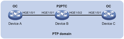
Network configuration
As shown in Figure 7, a PTP domain contains Device A, Device B, and Device C.
· Configure all devices to use the IEEE 802.1AS PTP profile.
· Specify the OC clock node type for Device A and Device C, and the P2PTC clock node type for Device B. All clock nodes elect a GM through BMC based on their respective default GM attributes.
· Configure the peer delay measurement mechanism (p2p) for Device A and Device C.
Procedure
1. Configure Device A:
# Specify the IEEE 802.1AS PTP profile.
<DeviceA> system-view
[DeviceA] ptp profile 802.1AS
# Specify the OC clock node type.
[DeviceA] ptp mode oc
# Specify PTP for obtaining the time.
[DeviceA] clock protocol ptp
# Enable PTP on HundredGigE 1/0/1.
[DeviceA] interface hundredgige 1/0/1
[DeviceA-HundredGigE1/0/1] ptp enable
[DeviceA-HundredGigE1/0/1] quit
2. Configure Device B:
# Specify the IEEE 802.1AS PTP profile.
<DeviceB> system-view
[DeviceB] ptp profile 802.1AS
# Specify the P2PTC clock node type.
[DeviceB] ptp mode p2ptc
# Specify PTP for obtaining the time.
[DeviceB] clock protocol ptp
# Enable PTP on HundredGigE 1/0/1.
[DeviceB] interface hundredgige 1/0/1
[DeviceB-HundredGigE1/0/1] ptp enable
[DeviceB-HundredGigE1/0/1] quit
# Enable PTP on HundredGigE 1/0/2.
[DeviceB] interface hundredgige 1/0/2
[DeviceB-HundredGigE1/0/2] ptp enable
[DeviceB-HundredGigE1/0/2] quit
3. Configure Device C:
# Specify the IEEE 1588 802.1AS PTP profile.
<DeviceC> system-view
[DeviceC] ptp profile 802.1AS
# Specify the OC clock node type.
[DeviceC] ptp mode oc
# Specify PTP for obtaining the time.
[DeviceC] clock protocol ptp
# Enable PTP on HundredGigE 1/0/1.
[DeviceC] interface hundredgige 1/0/1
[DeviceC-HundredGigE1/0/1] ptp enable
[DeviceC-HundredGigE1/0/1] quit
Verifying the configuration
When the network is stable, perform the following tasks to verify that Device A is elected as the GM, HundredGigE1/0/1 on Device A is the master port, and Device B has synchronized to Device A:
· Use the display ptp clock command to display PTP clock information.
· Use the display ptp interface brief command to display brief PTP statistics on an interface.
# Display PTP clock information on Device A.
[DeviceA] display ptp clock
PTP profile : IEEE 802.1AS
PTP mode : OC
Slave only : No
Clock ID : 000FE2-FFFE-FF0000
Clock type : Local
Clock domain : 0
Number of PTP ports : 1
Priority1 : 246
Priority2 : 248
Clock quality :
Class : 248
Accuracy : 254
Offset (log variance) : 16640
Offset from master : 0 (ns)
Mean path delay : 0 (ns)
Steps removed : 0
Local clock time : Sun Jan 15 20:57:29 2011
# Display brief PTP statistics on Device A.
[DeviceA] display ptp interface brief
Name State Delay mechanism Clock step Asymmetry correction
HGE1/0/1 Master P2P Two 0
# Display PTP clock information on Device B.
[DeviceB] display ptp clock
PTP profile : IEEE 802.1AS
PTP mode : P2PTC
Slave only : No
Clock ID : 000FE2-FFFE-FF0001
Clock type : Local
Clock domain : 0
Number of PTP ports : 2
Priority1 : 246
Priority2 : 248
Clock quality :
Class : 248
Accuracy : 254
Offset (log variance) : 16640
Offset from master : N/A
Mean path delay : N/A
Steps removed : N/A
Local clock time : Sun Jan 15 20:57:29 2011
# Display brief PTP statistics on Device B.
[DeviceB] display ptp interface brief
Name State Delay mechanism Clock step Asymmetry correction
HGE1/0/1 N/A P2P Two 0
HGE1/0/2 N/A P2P Two 0
Example: Configuring PTP (SMPTE ST 2059-2, multicast transmission)
Network configuration
As shown in Figure 8, Device A, Device B, and Device C are in a PTP domain. Configure PTP (SMPTE ST 2059-2, multicast transmission) on the three devices as follows for time synchronization:
· Configure the devices to use the SMPTE ST 2059-2 PTP profile.
· Configure the source IP address for multicast PTP message transmission over UDP.
· Specify the OC clock node type for Device A and Device C, and the P2PTC clock node type for Device B. All clock nodes elect a GM through BMC based on their respective default GM attributes.
· Configure the peer delay measurement mechanism (p2p) for Device A and Device C.

Procedure
1. Configure Device A:
# Specify the SMPTE ST 2059-2 PTP profile.
<DeviceA> system-view
[DeviceA] ptp profile st2059-2
# Specify the OC clock node type.
[DeviceA] ptp mode oc
# Configure the source IP address for multicast PTP message transmission over UDP.
[DeviceA] ptp source 10.10.10.1
# Specify PTP for obtaining the time.
[DeviceA] clock protocol ptp
# On HundredGigE 1/0/1, specify the delay measurement mechanism as p2p and enable PTP.
[DeviceA] interface hundredgige 1/0/1
[DeviceA-HundredGigE1/0/1] ptp transport-protocol udp [DeviceA-HundredGigE1/0/1] ptp delay-mechanism p2p
[DeviceA-HundredGigE1/0/1] ptp enable
[DeviceA-HundredGigE1/0/1] quit
2. Configure Device B:
# Specify the SMPTE ST 2059-2 PTP profile.
<DeviceB> system-view
[DeviceB] ptp profile st2059-2
# Specify the P2PTC clock node type.
[DeviceB] ptp mode p2ptc
# Configure the source IP address for multicast PTP message transmission over UDP.
[DeviceB] ptp source 10.10.10.2
# Specify PTP for obtaining the time.
[DeviceB] clock protocol ptp
# On HundredGigE 1/0/1, enable PTP.
[DeviceB] interface hundredgige 1/0/1
DeviceB-HundredGigE1/0/1] ptp transport-protocol udp
[DeviceB-HundredGigE1/0/1] ptp enable
[DeviceB-HundredGigE1/0/1] quit
# On HundredGigE 1/0/2, enable PTP.
[DeviceB] interface hundredgige 1/0/2
[DeviceB-HundredGigE1/0/2] ptp transport-protocol udp
[DeviceB-HundredGigE1/0/2] ptp enable
[DeviceB-HundredGigE1/0/2] quit
3. Configure Device C:
# Specify the SMPTE ST 2059-2 PTP profile.
<DeviceC> system-view
[DeviceC] ptp profile st2059-2
# Specify the OC clock node type.
[DeviceC] ptp mode oc
# Configure the source IP address for multicast PTP message transmission over UDP.
[DeviceC] ptp source 10.10.10.3
# Specify PTP for obtaining the time.
[DeviceC] clock protocol ptp
# On HundredGigE 1/0/1, specify the delay measurement mechanism as p2p and enable PTP.
[DeviceC] interface hundredgige 1/0/1
[DeviceC-HundredGigE1/0/1] ptp transport-protocol udp [DeviceC-HundredGigE1/0/1] ptp delay-mechanism p2p
[DeviceC-HundredGigE1/0/1] ptp enable
[DeviceC-HundredGigE1/0/1] quit
Verifying the configuration
When the network is stable, perform the following tasks to verify the PTP configuration:
· Use the display ptp clock command to display PTP clock information.
· Use the display ptp interface brief command to display brief PTP statistics on an interface.
# Display PTP clock information on Device A.
[DeviceA] display ptp clock
PTP profile : SMPTE ST 2059-2
PTP mode : OC
Slave only : No
Clock ID : 000FE2-FFFE-FF0000
Clock type : Local
Clock domain : 0
Number of PTP ports : 1
Priority1 : 128
Priority2 : 128
Clock quality :
Class : 248
Accuracy : 254
Offset (log variance) : 65535
Offset from master : 0 (ns)
Mean path delay : 0 (ns)
Steps removed : 0
Local clock time : Sun Jan 15 20:57:29 2011
# Display brief PTP statistics on Device A.
[DeviceA] display ptp interface brief
Name State Delay mechanism Clock step Asymmetry correction
GE1/0/1 Master P2P Two 0
# Display PTP clock information on Device B.
[DeviceB] display ptp clock
PTP profile : SMPTE ST 2059-2
PTP mode : P2PTC
Slave only : No
Clock ID : 000FE2-FFFE-FF0001
Clock type : Local
Clock domain : 0
Number of PTP ports : 2
Priority1 : 128
Priority2 : 128
Clock quality :
Class : 248
Accuracy : 254
Offset (log variance) : 65535
Offset from master : N/A
Mean path delay : N/A
Steps removed : N/A
Local clock time : Sun Jan 15 20:57:29 2011
# Display brief PTP statistics on Device B.
[DeviceB] display ptp interface brief
Name State Delay mechanism Clock step Asymmetry correction
GE1/0/1 N/A P2P Two 0
GE1/0/2 N/A P2P Two 0
The output shows that Device A is elected as the GM and HundredGigE1/0/1 on Device A is the master port.
Example: Configuring PTP (SMPTE ST 2059-2, unicast transmission)
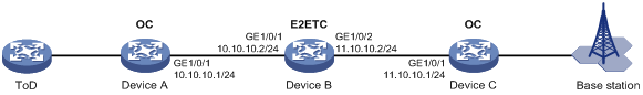
Network configuration
As shown in Figure 9, Device A, Device B, and Device C are in a PTP domain. Device A is the GM and receives the ToD clock signals. Device C sends ToD clock signals to the base station through its ToD interface.
· Configure all devices to use the SMPTE ST 2059-2 PTP profile.
· Configure the destination IP address for unicast PTP messages transmission over UDP.
· Specify the OC clock node type for Device A and Device C, and the E2ETC clock node type for Device B.
· Configure the peer delay measurement mechanism (p2p) for Device A and Device C.
Procedure
1. Assign IP addresses to the interfaces, and make sure the devices can reach each other, as shown in Figure 9. (Details not shown.)
2. Configure Device A:
# Specify the SMPTE ST 2059-2 PTP profile.
<DeviceA> system-view
[DeviceA] ptp profile st2059-2
# Specify the OC clock node type.
[DeviceA] ptp mode oc
# Configure the device to receive ToD 0 clock signals and set the delay correction value to 1000 nanoseconds.
[DeviceA] ptp tod0 input delay 1000
# Set priority 1 to 0 for the ToD 0 clock.
[DeviceA] ptp priority clock-source tod0 priority1 0
# On HundredGigE 1/0/1, configure the destination IP address for unicast PTP messages and enable PTP.
[DeviceA] interface hundredgige 1/0/1
[DeviceA-HundredGigE1/0/1] ptp transport-protocol udp
[DeviceA-HundredGigE1/0/1] ptp unicast-destination 10.10.10.2
[DeviceA-HundredGigE1/0/1] ptp enable
[DeviceA-HundredGigE1/0/1] quit
3. Configure Device B:
# Specify the SMPTE ST 2059-2 PTP profile.
<DeviceB> system-view
[DeviceB] ptp profile st2059-2
# Specify the E2ETC clock node type.
[DeviceB] ptp mode e2etc
# Specify PTP for obtaining the time.
[DeviceB] clock protocol ptp
# On HundredGigE 1/0/1, configure the destination IP address for unicast PTP messages and enable PTP.
[DeviceB] interface hundredgige 1/0/1
[DeviceB-HundredGigE1/0/1] ptp unicast-destination 10.10.10.1
[DeviceB-HundredGigE1/0/1] ptp enable
[DeviceB-HundredGigE1/0/1] quit
# On HundredGigE 1/0/2, configure the destination IP address for unicast PTP messages and enable PTP.
[DeviceB] interface hundredgige 1/0/2
[DeviceB-HundredGigE1/0/2] ptp unicast-destination 11.10.10.1
[DeviceB-HundredGigE1/0/2] ptp enable
[DeviceB-HundredGigE1/0/2] quit
4. Configure Device C:
# Specify the SMPTE ST 2059-2 PTP profile.
<DeviceC> system-view
[DeviceC] ptp profile st2059-2
# Specify the OC clock node type.
[DeviceC] ptp mode oc
# Configure the device to send ToD 0 clock signals and set the delay correction value to 1000 nanoseconds.
[DeviceC] ptp tod0 output delay 100
# Specify PTP for obtaining the time.
[DeviceC] clock protocol ptp
# On HundredGigE 1/0/1, configure the destination IP address for unicast PTP messages and enable PTP.
[DeviceC] interface hundredgige 1/0/1
[DeviceC-HundredGigE1/0/1] ptp transport-protocol udp
[DeviceC-HundredGigE1/0/1] ptp unicast-destination 11.10.10.2
[DeviceC-HundredGigE1/0/1] ptp enable
[DeviceC-HundredGigE1/0/1] quit
Verifying the configuration
When the network is stable, perform the following tasks to verify the PTP configuration:
· Use the display ptp clock command to display PTP clock information.
· Use the display ptp interface brief command to display brief PTP running information.
# Display PTP clock information on Device A.
[DeviceA] display ptp clock
PTP profile : SMPTE ST 2059-2
PTP mode : OC
Slave only : No
Clock ID : 000FE2-FFFE-FF0000
Clock type : ToD0
ToD direction : In
ToD delay time : 1000 (ns)
Clock domain : 0
Number of PTP ports : 1
Priority1 : 0
Priority2 : 128
Clock quality :
Class : 6
Accuracy : 32
Offset (log variance) : 65535
Offset from master : 0 (ns)
Mean path delay : 0 (ns)
Steps removed : 0
Local clock time : Sun Jan 15 20:57:29 2011
# Display brief PTP running information on Device A.
[DeviceA] display ptp interface brief
Name State Delay mechanism Clock step Asymmetry correction
GE1/0/1 Master E2E Two 0
# Display PTP clock information on Device B.
[DeviceB] display ptp clock
PTP profile : SMPTE ST 2059-2
PTP mode : E2ETC
Slave only : No
Clock ID : 000FE2-FFFE-FF0001
Clock type : Local
Clock domain : 0
Number of PTP ports : 2
Priority1 : 128
Priority2 : 128
Clock quality :
Class : 248
Accuracy : 254
Offset (log variance) : 65535
Offset from master : N/A
Mean path delay : N/A
Steps removed : N/A
Local clock time : Sun Jan 15 20:57:29 2011
# Display brief PTP running information on Device B.
[DeviceB] display ptp interface brief
Name State Delay mechanism Clock step Asymmetry correction
GE1/0/1 N/A E2E Two 0
GE1/0/2 N/A E2E Two 0