- Table of Contents
- Related Documents
-
| Title | Size | Download |
|---|---|---|
| 02-Ethernet interface configuration | 182.52 KB |
Configuring Ethernet interfaces
Configuring common Ethernet interface settings
Ethernet interface numbering conventions
Configuring the physical type for a combo interface (single combo interface)
Changing the interface type of a 10-GE interface
Configuring the operating mode for a 10-GE interface
Setting the J0 and J1 overhead bytes for a 10-GE interface
Configuring basic settings of an Ethernet interface
Configuring basic settings of an Ethernet subinterface
Configuring the link mode of an Ethernet interface
Configuring jumbo frame support
Configuring physical state change suppression on an Ethernet interface
Configuring dampening on an Ethernet interface
Configuring generic flow control on an Ethernet interface
Configuring PFC on an Ethernet interface
Forcibly bringing up a fiber port
Setting the statistics polling interval
Enabling loopback testing on an Ethernet interface
Configuring interface alarm functions
Restoring the default settings for an interface
Setting protocol group rate limits
Configuring a Layer 2 Ethernet interface
Configuring storm control on an Ethernet interface
Configuring a Layer 3 Ethernet interface or subinterface
Setting the MTU for an Ethernet interface or subinterface
Setting the MAC address of an Ethernet interface or subinterface
Enabling packet statistics collection on a Layer 3 Ethernet subinterface
Display and maintenance commands for an Ethernet interface or subinterface
Configuring Ethernet interfaces
About Ethernet interface
Your device supports the following types of Ethernet interfaces:
· Layer 2 Ethernet interfaces—Physical Ethernet interfaces operating at the data link layer (Layer 2) to switch packets.
· Layer 3 Ethernet interfaces—Physical Ethernet interfaces operating at the network layer (Layer 3) to route packets. You can assign an IP address to a Layer 3 Ethernet interface.
· Layer-configurable Ethernet interfaces—Physical Ethernet interfaces that can be configured to operate in bridge mode as Layer 2 Ethernet interfaces or in route mode as Layer 3 Ethernet interfaces.
· Layer 3 Ethernet subinterfaces—Logical interfaces operating at the network layer. You can assign an IP address to a Layer 3 Ethernet subinterface. To enable a Layer 3 Ethernet interface to transport packets for multiple VLANs, you must create Layer 3 subinterfaces on the Layer 3 Ethernet interface. For information about how a Layer 3 Ethernet subinterface sends and receives VLAN-tagged packets, see Layer 2—LAN Switching Configuration Guide.
Configuring common Ethernet interface settings
This section describes the settings common to Layer 2 Ethernet interfaces, Layer 3 Ethernet interfaces, and Layer 3 Ethernet subinterfaces. For more information about the settings specific to Layer 2 Ethernet interfaces, see "Configuring a Layer 2 Ethernet interface." For more information about the settings specific to Layer 3 Ethernet interfaces or subinterfaces, see "Configuring a Layer 3 Ethernet interface or subinterface."
Ethernet interface numbering conventions
When the device operates in standalone mode, an Ethernet interface is numbered in the format of
interface type A/B/C, where:
· A is the slot number of the card where the Ethernet interface resides.
· B is the number of the subcard where the Ethernet interface resides.
If the card does not have any subcard, B is fixed at 0.
· C is the interface number.
When the device operates in IRF mode, an Ethernet interface is numbered in the format of interface type A/B/C/D, where:
· A is the ID of the IRF member device where the Ethernet interface resides.
A can be 1 or 2.
· B is the slot number of the card where the Ethernet interface resides.
· C is the number of the subcard where the Ethernet interface resides.
If the card does not have any subcard, C is fixed at 0.
· D is the interface number.
Configuring the physical type for a combo interface (single combo interface)
About combo interface
A combo interface is a logical interface that physically comprises one fiber combo port and one copper combo port. The two ports share one forwarding channel and one interface view. As a result, they cannot work simultaneously. When you activate one port, the other port is automatically disabled. In the interface view, you can activate the fiber or copper combo port, and configure other port attributes such as the interface rate and duplex mode.
Prerequisites
Before you configure combo interfaces, complete the following tasks:
· Determine the combo interfaces on your device. Identify the two physical interfaces that belong to each combo interface according to the marks on the device panel.
· Use the display interface command to determine which port (fiber or copper) of each combo interface is active:
¡ If the copper port is active, the output includes "Media type is twisted pair, Port hardware type is 1000_BASE_T."
¡ If the fiber port is active, the output does not include this information.
Also, you can use the display this command in the view of each combo interface to display the combo interface configuration:
¡ If the fiber port is active, the combo enable fiber command exists in the output.
¡ If the copper port is active, the combo enable fiber command does not exist in the output.
Restrictions and guidelines
Follow these restrictions when you activate the fiber combo port of a combo interface:
· On an MIC-GP4L interface subcard in a CSPEX-1104-E or CSPEX-1204 card, the fiber combo port of a combo interface does not support 100-Mbps transceiver modules, 100/1000-Mbps transceiver modules, or fiber-to-copper converters.
· On an MIC-GP4L interface subcard in any other CSPEX card, the fiber combo port of a combo interface does not support 100-Mbps transceiver modules or fiber-to-copper converters.
· On other interface subcards, the fiber combo port of a combo interface does not support 100-Mbps transceiver modules, 100/1000-Mbps transceiver modules, or fiber-to-copper converters.
The combo enable command does not take effect on a combo interface in a service loopback group.
Procedure
1. Enter system view.
system-view
2. Enter Ethernet interface view.
interface interface-type interface-number
3. Activate the copper combo port or fiber combo port.
combo enable { copper | fiber }
By default, the copper combo port is active.
Changing the interface type of a 10-GE interface
About interface type change between 10-GE interface and GE interface
Change a 10-GE interface to a GE interface when either of the following conditions exists:
· The peer is a GE interface.
· No 10-GE transceiver module is available, and GE transceiver modules are available.
If you need higher bandwidth, you can restore a GE interface that was changed from a 10-GE interface to a 10-GE interface.
Restrictions and guidelines for interface change between 10-GE interface and GE interface
After you configure this feature, this feature takes effect immediately. To reboot the device, you must save the configuration before rebooting the device.
Only the following interfaces support this command:
· All interfaces on the MIC-XP20L, MIC-XP2L, MIC-XP2L-LAN, and MIC-XP4L1 subcards.
· The last four interfaces on a MIC-XP5L or MIC-XP5L1 subcard.
When you execute this command on an interface, this command changes two interfaces in the same group. For more information, see the command prompt. When a group contains an aggregation group member port, this command is not supported.
When a subcard slot is configured with this command, do not replace the subcard with a subcard of a different model.
Do not execute this command on interfaces of a card where the IRF physical interface resides.
After the interface type is changed, the interface operates in Layer 3 mode. After a 10-GE interface is changed to a GE interface, it support only the speed of 1000 Mbps.
Changing a 10-GE interface to a GE interface
1. Enter system view.
system-view
2. Enter 10-GE interface view.
interface ten-gigabitethernet interface-number
3. Change the 10-GE interface to a GE interface.
using gigabit
By default, a 10-GE interface is not changed to a GE interface.
Restoring a GE interface that was changed from a 10-GE interface to a 10-GE interface
1. Enter system view.
system-view
2. Enter the view of a GE interface that was changed from a 10-GE interface.
interface gigabitethernet interface-number
3. Restore the GE interface to a 10-GE interface.
using tengige
By default, a GE interface is not changed to a 10-GE interface.
Configuring the operating mode for a 10-GE interface
About the operating modes for a 10-GE interface
10-GE interfaces support the following operating modes:
· LAN mode—In LAN mode, a 10-GE interface transmits Ethernet packets and provides Ethernet network access.
· WAN mode—In WAN mode, a 10-GE interface transmits SDH frames and provides SDH network access. In this mode, a 10-GE interface supports only point-to-point connections.
Restrictions and guidelines
Only interfaces on a PIC-XP1L, MIC-XP2L, MIC-XP4L1, MIC-XP5L1, or MIC-XP20L interface subcard and the last four interfaces on a MIC-XP5L interface subcard support this command.
A 10-GE interface operating in WAN mode encapsulates Ethernet packets in SDH frames. A 10G POS interface encapsulates PPP packets in SDH frames. However, they cannot communicate with each other because they encapsulate different kinds of packets.
Procedure
1. Enter system view.
system-view
2. Enter 10-GE interface view.
interface ten-gigabitethernet interface-number
3. Configure the 10-GE interface to operate in LAN or WAN mode.
port-mode { lan | wan }
By default, a 10-GE interface operates in LAN mode.
Setting the J0 and J1 overhead bytes for a 10-GE interface
About the J0 and J1 overhead bytes for a 10-GE interface
The overhead bytes in SDH frames provide the operation and maintenance features such as hierarchical management of the transmission network. J0 and J1 bytes provide internetworking support between devices of different countries, regions, or vendors.
The Regenerator Section Trace byte J0 is usually configured as a section access point identifier. The sending end keeps the connection with the receiving end by sending this byte repeatedly.
The Path Trace byte J1 is usually configured as a high-order path access point identifier. J1 also enables two ends to keep their connection.
To ensure smooth communication, make sure the sending and receiving ends have the same J0 and J1 bytes.
Procedure
1. Enter system view.
system-view
2. Enter 10-GE interface view.
interface ten-gigabitethernet interface-number
3. Configure the 10-GE interface to operate in WAN mode.
port-mode wan
By default, a 10-GE interface operates in LAN mode.
4. Set the J0 and J1 bytes.
flag { j0 | j1 } sdh flag-value
By default, the value for the Regenerator Section Trace byte J0 is CR16000.
Configuring basic settings of an Ethernet interface
About Ethernet interface basic settings
You can configure an Ethernet interface to operate in one of the following duplex modes:
· Full-duplex mode—The interface can send and receive packets simultaneously.
· Half-duplex mode—The interface can only send or receive packets at a given time.
· Autonegotiation mode—The interface negotiates a duplex mode with its peer.
You can set the speed of an Ethernet interface or enable it to automatically negotiate a speed with its peer.
Restrictions and guidelines
When a MIC-XP4L1, MIC-XP2L, or MIC-XP2L-LAN subcard is installed in a CSPEX-1104-E card and a 10-GE interface on the subcard has a 1-Gbps transceiver module installed, set the duplex mode to full and speed to 1000 for both the local and remote interfaces.
When you configure the duplex mode, follow these restrictions and guidelines:
· Fiber ports do not support the half keyword.
· When a subcard is installed in a CSPEX-1104-E or CSPEX-1204 card, copper ports on the subcard do not support the half duplex mode. When a subcard is installed in any other CSPEX card, only copper ports on a MIC-GP4L subcard support the half duplex mode.
For GE interfaces on PIC-TCP8L subcards, the speed cannot be manually set and can be autonegotiated only to 1000 Mbps.
When you configure the speed, follow these restrictions and guidelines:
· 40GE and 100GE interfaces can only operate at their highest speed.
· For interfaces on a MIC subcard in a CSPEX-1104-E or CSPEX-1204 card, the speed can be set to only 1000Mbps or auto.
· When a fiber pot on a PIC-GP10L subcard is directly connected to a fiber port on a fiber port on a MIC subcard or GE CSPC (CSPC-GE16XP4L-E, CSPC-GE24L-E, and CSPC-GP24GE8XP2L-E) card (for example, CSPC-GP48LB), if the speed is set to 1000 Mbps for one end by using this command, set the speed to auto for the other end.
The shutdown, port up-mode, and loopback commands are mutually exclusive.
Procedure
1. Enter system view.
system-view
2. Enter Ethernet interface view.
interface interface-type interface-number
3. Set the description for the Ethernet interface.
description text
The default setting is interface-name Interface. For example, GigabitEthernet3/1/1 Interface.
4. Set the duplex mode for the Ethernet interface.
duplex { auto | full | half }
By default:
¡ The duplex mode is full for 10-GE, 40-GE, and 100-GE interfaces.
¡ The duplex mode is auto for other Ethernet interfaces.
5. Set the speed for the Ethernet interface.
speed { 10 | 100 | 1000 | 10000 | 40000 | 100000 | auto }
By default, a GE interface negotiates a speed with its peer, and a 10-GE, 40-GE, or 100-GE interface operates at its highest speed.
6. Set the expected bandwidth for the Ethernet interface.
bandwidth bandwidth-value
By default, the expected bandwidth (in kbps) is the interface baud rate divided by 1000.
7. Bring up the Ethernet interface.
undo shutdown
By default, the Ethernet interface is up.
Configuring basic settings of an Ethernet subinterface
Restrictions and guidelines for Ethernet subinterface basic settings
· To transmit and receive packets through an Ethernet subinterface, you must associate it with a VLAN. For more information, see Layer 2—LAN Switching Configuration Guide.
· To transmit packets between a local Ethernet subinterface and a remote Ethernet subinterface, configure them with the same subinterface number and VLAN ID.
· The shutdown, port up-mode, and loopback commands are mutually exclusive.
Procedure
1. Enter system view.
system-view
2. Create an Ethernet subinterface.
interface interface-type interface-number.subnumber
3. Set the description for the Ethernet subinterface.
description text
The default setting is interface-name Interface. For example, GigabitEthernet3/1/1.1 Interface.
4. Set the expected bandwidth for the Ethernet subinterface.
bandwidth bandwidth-value
By default, the expected bandwidth (in kbps) is the interface baud rate divided by 1000.
5. Bring up the Ethernet subinterface.
undo shutdown
By default, the Ethernet subinterface is up.
Configuring the link mode of an Ethernet interface
About the link mode of an Ethernet interface
Interfaces on the device can operate either as Layer 2 or Layer 3 Ethernet interfaces. You can use commands to set the link mode to bridge or route.
Restrictions and guidelines
After you change the link mode of an Ethernet interface, all commands (except shutdown and combo enable) on the Ethernet interface are restored to their defaults in the new link mode.
Procedure
1. Enter system view.
system-view
2. Enter Ethernet interface view.
interface interface-type interface-number
3. Configure the link mode of the Ethernet interface.
port link-mode { bridge | route }
By default, the Ethernet interface operates in Layer 3 mode.
Configuring jumbo frame support
About jumbo frame
Jumbo frames are frames larger than a fixed size and are typically received by an Ethernet interface during high-throughput data exchanges, such as file transfers.
The Ethernet interface processes jumbo frames in the following ways:
· When you configure the Ethernet interface to deny jumbo frames by using the undo jumboframe enable command, the Ethernet interface discards jumbo frames.
· When you configure the Ethernet interface with jumbo frame support, the Ethernet interface performs the following operations:
¡ Processes jumbo frames within the specified length.
¡ Discards jumbo frames that exceed the specified length.
Restrictions and guidelines
Interfaces on CSPEX (except CSPEX-1204 and CSPEX-1104-E) and CEPC cards do not support this feature.
Procedure
1. Enter system view.
system-view
2. Enter Ethernet interface view.
interface interface-type interface-number
3. Configure jumbo frame support.
jumboframe enable [ size ]
By default, the device allows jumbo frames within the specified length to pass through all Layer 2 Ethernet interfaces.
If you set the size argument multiple times, the most recent configuration takes effect.
Configuring physical state change suppression on an Ethernet interface
About physical state change suppression
The physical link state of an Ethernet interface is either up or down. Each time the physical link of an interface comes up or goes down, the interface immediately reports the change to the CPU. The CPU then performs the following operations:
· Notifies the upper-layer protocol modules (such as routing and forwarding modules) of the change for guiding packet forwarding.
· Automatically generates traps and logs to inform users to take the correct actions.
To prevent frequent physical link flapping from affecting system performance, configure physical state change suppression. You can configure this feature to suppress only link-down events, only link-up events, or both. If an event of the specified type still exists when the suppression interval expires, the system reports the event to the CPU.
Restrictions and guidelines
Do not enable this feature on an interface that has spanning tree protocols enabled.
You can configure different suppression intervals for link-up and link-down events.
If you configure this command multiple times for link-up or link-down events on an Ethernet interface, the most recent configuration takes effect.
Procedure
1. Enter system view.
system-view
2. Enter Ethernet interface view.
interface interface-type interface-number
3. Configure physical state change suppression.
link-delay [ msec ] delay-time [ mode { up | updown } ]
By default, the physical state change suppression interval is 1 second.
To suppress only link-down events, do not specify the mode keyword. To suppress only link-up events, specify the mode up keywords. To suppress both link-down and link-up events, specify the mode updown keywords.
Configuring dampening on an Ethernet interface
About dampening
The interface dampening feature uses an exponential decay mechanism to prevent excessive interface flapping events from adversely affecting routing protocols and routing tables in the network. Suppressing interface state change events protects the system resources.
If an interface is not dampened, its state changes are reported. For each state change, the system also generates an SNMP trap and log message.
After a flapping interface is dampened, it does not report its state changes to the CPU. For state change events, the interface only generates SNMP trap and log messages.
Parameters
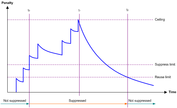
· Penalty—The interface has an initial penalty of 0. When the interface flaps, the penalty increases by 1000 for each down event until the ceiling is reached. It does not increase for up events. When the interface stops flapping, the penalty decreases by half each time the half-life timer expires until the penalty drops to the reuse threshold.
· Ceiling—The penalty stops increasing when it reaches the ceiling.
· Suppress-limit—The accumulated penalty that triggers the device to dampen the interface. In dampened state, the interface does not report its state changes to the CPU. For state change events, the interface only generates SNMP traps and log messages.
· Reuse-limit—When the accumulated penalty decreases to this reuse threshold, the interface is not dampened. Interface state changes are reported to the upper layers. For each state change, the system also generates an SNMP trap and log message.
· Decay—The amount of time (in seconds) after which a penalty is decreased.
· Max-suppress-time—The maximum amount of time the interface can be dampened. If the penalty is still higher than the reuse threshold when this timer expires, the penalty stops increasing for down events. The penalty starts to decrease until it drops below the reuse threshold.
When configuring the dampening command, follow these rules to set the values mentioned above:
· The ceiling is equal to 2(Max-suppress-time/Decay) × reuse-limit. It is not user configurable.
· The configured suppress limit is lower than or equal to the ceiling.
· The ceiling is lower than or equal to the maximum suppress limit supported.
Figure 1 shows the change rule of the penalty value. The lines t0 and t2 indicate the start time and end time of the suppression, respectively. The period from t0 to t2 indicates the suppression period, t0 to t1 indicates the max-suppress-time, and t1 to t2 indicates the complete decay period.
Figure 1 Change rule of the penalty value
Restrictions and guidelines
· The dampening command and the link-delay command cannot be configured together on an interface.
· The dampening command does not take effect on the administratively down events. When you execute the shutdown command, the penalty restores to 0, and the interface reports the down event to the upper-layer protocols.
· Do not enable the dampening feature on an interface with MSTP enabled.
Procedure
1. Enter system view.
system-view
2. Enter Ethernet interface view.
interface interface-type interface-number
3. Enable dampening on the interface.
dampening [ half-life reuse suppress max-suppress-time ]
By default, interface dampening is disabled on Ethernet interfaces.
Configuring FEC
About FEC
The forward error correction (FEC) feature corrects packet errors to improve transmission quality. It attaches correction information to a packet at the sending end, and corrects error codes generated during transmission at the receiving end based on the correction information. You can set the FEC mode as needed.
Restrictions and guidelines
This feature is supported only on 100-GE interfaces.
You can modify the FEC mode for only 100-GE interfaces that support the QSFP28 transceiver modules.
Make sure you set the same FEC mode for both interfaces of a link.
Procedure
1. Enter system view.
system-view
2. Enter Ethernet interface view.
interface interface-type interface-number
3. Set the FEC mode of the Ethernet interface.
port fec mode { auto | none | rs-fec }
By default, the FEC mode of 100-GE interfaces is auto.
Configuring generic flow control on an Ethernet interface
About generic flow control
To avoid dropping packets on a link, you can enable generic flow control at both ends of the link. When traffic congestion occurs at the receiving end, the receiving end sends a flow control (Pause) frame to ask the sending end to suspend sending packets. Generic flow control includes the following types:
· TxRx-mode generic flow control—Enabled by using the flow-control command. With TxRx-mode generic flow control enabled, an interface can both send and receive flow control frames:
¡ When congestion occurs, the interface sends a flow control frame to its peer.
¡ When the interface receives a flow control frame from its peer, it suspends sending packets to its peer.
· Rx-mode generic flow control—Enabled by using the flow-control receive enable command. With Rx-mode generic flow control enabled, an interface can receive flow control frames, but it cannot send flow control frames:
¡ When congestion occurs, the interface cannot send flow control frames to its peer.
¡ When the interface receives a flow control frame from its peer, it suspends sending packets to its peer.
To handle unidirectional traffic congestion on a link, configure the flow-control receive enable command at one end and the flow-control command at the other end. To enable both ends of a link to handle traffic congestion, configure the flow-control command at both ends.
Restrictions and guidelines
Interfaces on MIC interface subcards in a CSPEX-1104-E or CSPEX-1204 card do not support this feature.
Procedure
1. Enter system view.
system-view
2. Enter Ethernet interface view.
interface interface-type interface-number
3. Enable generic flow control.
¡ Enable TxRx-mode generic flow control:
flow-control
¡ Enable Rx-mode generic flow control:
flow-control receive enable
By default, generic flow control is disabled on an Ethernet interface.
Configuring PFC on an Ethernet interface
About PFC
When congestion occurs in the network, the local device buffers packets if the following conditions exist:
· The local device has PFC enabled and the priority-flow-control no-drop dot1p command configured.
· The local device receives a packet carrying a 802.1p priority that is in the 802.1p priority list specified by the dot1p-list argument.
When the number of buffered packets reaches a certain value, the local device notifies the remote device to stop sending packets if the following conditions exist:
· The incoming interface on the local device is configured with the flow-control command.
· The outgoing interface on the remote device is configured with the flow-control or flow-control receive enable command.
When congestion disappears, the local device notifies the remote device to restore packet sending.
The state of the PFC feature is determined by the PFC configuration on the local end and on the peer end. In Table 1:
· The first row lists the PFC configuration on the local interface.
· The first column lists the PFC configuration on the peer.
· The Enabled and Disabled fields in other cells are possible negotiation results.
Make sure all interfaces that a data flow passes through have the same PFC configuration.
Table 1 PFC configurations and negotiation results
|
Local (right) Peer (below) |
enable |
auto |
Default |
|
enable |
Enabled |
Enabled. |
Disabled |
|
auto |
Enabled |
· Enabled if negotiation succeeds. · Disabled if negotiation fails. |
Disabled |
|
Default |
Disabled |
Disabled. |
Disabled |
Restrictions and guidelines
· This feature is supported only when type-B or type-D switching fabric modules are used.
· Only CSPC (except CSPC-GE16XP4L-E, CSPC-GE24L-E, and CSPC-GP24GE8XP2L-E) cards with an interface capacity more than 80 Gbps support this feature. The interface capacity of a card refers to the sum of the speed of each interface on the card. For example, the interface capacity of a CSPC-CP2LB card is 200 Gbps (2 × 100 Gbps).
· In IRF mode, this feature is supported only when the incoming interface and outgoing interface are on the same member device.
· For PFC to take effect, make sure flow control is enabled on both the local incoming interface and peer outgoing interface and PFC is enabled.
Procedure
1. Enter system view.
system-view
2. Enable PFC in auto mode or forcibly.
priority-flow-control { auto | enable }
By default, PFC is disabled.
3. Enable PFC for 802.1p priorities.
priority-flow-control no-drop dot1p dot1p-list
By default, PFC is disabled for all 802.1p priorities.
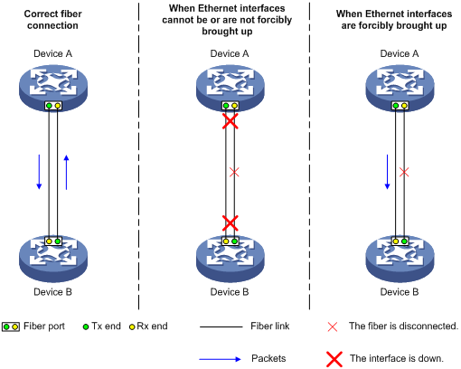
Forcibly bringing up a fiber port
About forcibly bringing up a fiber port
As shown in Figure 2, a fiber port uses separate fibers for transmitting and receiving packets. The physical state of the fiber port is up only when both transmit and receive fibers are physically connected. If one of the fibers is disconnected, the fiber port does not work.
To enable a fiber port to forward traffic over a single link, you can use the port up-mode command. This command forcibly brings up a fiber port, even when no fiber links or transceiver modules are present for the fiber port. When one fiber link is present and up, the fiber port can forward packets over the link unidirectionally.
Figure 2 Forcibly bring up a fiber port
Restrictions and guidelines
· Only 10-GE fiber ports operating in LAN mode, GE fiber ports, 40-GE, and 100-GE fiber ports support this feature. Copper ports and combo interfaces do not support this feature.
· Interfaces on CSPC-GE16XP4L-E, CSPC-GE24L-E, CSPC-GP24GE8XP2L-E, CSPEX, and CEPC do not support this feature.
· The shutdown, port up-mode, and loopback commands are mutually exclusive.
· A fiber port forcibly brought up stays physically up whether or not a transceiver module or a fiber link is present for the port.
· A GE fiber port forcibly brought up cannot correctly forward traffic if it is installed with a fiber-to-copper converter, 100/1000-Mbps transceiver module, or 100-Mbps transceiver module. To solve the problem, use the undo port up-mode command on the fiber port.
Procedure
1. Enter system view.
system-view
2. Enter Ethernet interface view.
interface interface-type interface-number
3. Forcibly bring up the fiber port.
port up-mode
By default, a fiber port is not forcibly brought up, and the physical state of a fiber port depends on the physical state of the fibers.
Setting the statistics polling interval
Restrictions and guidelines for setting the statistics polling interval
To display the interface statistics collected in the last statistics polling interval, use the display interface command.
You can use this command in system view or interface view.
· In system view, the command takes effect on all interfaces.
· In interface view, the command takes effect only on the specified interface.
When the statistics polling interval uses the default setting in interface view, the setting in system view takes effect. When the command is configured in both system view and interface view, the setting in interface view takes priority.
As a best practice, use the default statistics polling interval in system view. A short statistics polling interval in system view might decrease the system performance and result in inaccurate statistics.
Setting the statistics polling interval in system view
1. Enter system view.
system-view
2. Set the statistics polling interval.
flow-interval interval
By default, the statistics polling interval is 300 seconds.
Setting the statistics polling interval in Ethernet interface view
1. Enter system view.
system-view
2. Enter Ethernet interface view.
interface interface-type interface-number
3. Set the statistics polling interval for the Ethernet interface.
flow-interval interval
By default, the statistics polling interval is 300 seconds.
Enabling loopback testing on an Ethernet interface
About loopback testing
Perform this task to determine whether an Ethernet link works correctly.
Loopback testing includes the following types:
· Internal loopback testing—Tests the device where the Ethernet interface resides. The Ethernet interface sends outgoing packets back to the local device. If the device fails to receive the packets, the device fails.
· External loopback testing—Tests the inter-device link. The Ethernet interface sends incoming packets back to the remote device. If the remote device fails to receive the packets, the inter-device link fails.
Restrictions and guidelines
CSPC-GE16XP4L-E, CSPC-GE24L-E, CSPC-GP24GE8XP2L-E, CSPEX, and CEPC cards do not support the external keyword.
The internal keyword can be configured but does not take effect on the following interfaces:
· The first interface on the MIC-XP5L subcard.
· Interfaces on the MIC-QP1L, MIC-XP2L-LAN, and MIC-CP1L subcards.
· Interfaces on the CEPC-XP48RX card.
After the following interfaces are switched to GE interfaces by using the using gigabit command, the GE interfaces do not support the internal keyword.
· All interfaces on the MIC-XP20L, MIC-XP2L, and MIC-XP4L1 subcards.
· The last four interfaces on each MIC-XP5L or MIC-XP5L1 subcard.
After you enable this feature on an Ethernet interface, the interface does not forward data traffic.
The shutdown, port up-mode, and loopback commands are mutually exclusive.
After you enable this feature on an Ethernet interface, the Ethernet interface switches to full duplex mode. After you disable this feature, the Ethernet interface restores to its duplex setting.
Procedure
1. Enter system view.
system-view
2. Enter Ethernet interface view.
interface interface-type interface-number
3. Enable loopback testing.
loopback { external | internal }
By default, loopback testing is disabled on an Ethernet interface.
Configuring interface alarm functions
About interface alarm functions
With the interface alarm functions enabled, when the number of sent or received error packets or the input or output bandwidth usage on an interface in normal state within the specified interval exceeds the upper threshold, the interface generates an upper threshold exceeding alarm and enters the alarm state. When the number of sent or received error packets or the input or output bandwidth usage on an interface in the alarm state within the specified interval drops below the lower threshold, the interface generates a recovery alarm and restores to the normal state.
Restrictions and guidelines
You can configure the error packet alarm parameters in system view and interface view.
· The configuration in system view takes effect on all interfaces of the specified slot. The configuration in interface view takes effect only on the current interface.
· For an interface, the configuration in interface view takes priority, and the configuration in system view is used only when no configuration is made in interface view.
An interface that is shut down because of error packet alarms cannot automatically recover. To bring up the interface, execute the undo shutdown command on the interface.
Enabling interface alarm functions
1. Enter system view.
system-view
2. Enable alarm functions for the interface monitoring module.
snmp-agent trap enable ifmonitor [ crc-error | input-error | input-usage | output-error | output-usage | rx-pause | sdh-b1-error | sdh-b2-error | sdh-error | tx-pause ] *
By default, all alarm functions are enabled for interfaces.
Configuring CRC error packet alarm parameters
1. Enter system view.
system-view
2. Configure global CRC error packet alarm parameters.
In standalone mode:
ifmonitor crc-error slot slot-number high-threshold high-value low-threshold low-value interval interval [ shutdown ]
In IRF mode:
ifmonitor crc-error chassis chassis-number slot slot-number high-threshold high-value low-threshold low-value interval interval [ shutdown ]
By default, the upper threshold is 1000, the lower threshold is 100, and the statistics collection and comparison interval is 10 seconds for CRC error packets.
3. Enter Ethernet interface view.
interface interface-type interface-number
4. Configure CRC error packet alarm parameters for the interface.
port ifmonitor crc-error [ ratio ] high-threshold high-value low-threshold low-value interval interval [ shutdown ]
By default, an interface uses the global CRC error packet alarm parameters.
Configuring input error packet alarm parameters
1. Enter system view.
system-view
2. Configure global input error packet alarm parameters.
In standalone mode:
ifmonitor input-error slot slot-number high-threshold high-value low-threshold low-value interval interval [ shutdown ]
In IRF mode:
ifmonitor input-error chassis chassis-number slot slot-number high-threshold high-value low-threshold low-value interval interval [ shutdown ]
By default, the upper threshold is 1000, the lower threshold is 100, and the statistics collection and comparison interval is 10 seconds for input error packets.
3. Enter Ethernet interface view.
interface interface-type interface-number
4. Configure input error packet alarm parameters for the interface.
port ifmonitor input-error high-threshold high-value low-threshold low-value interval interval [ shutdown ]
By default, an interface uses the global input error packet alarm parameters.
Configuring output error packet alarm parameters
1. Enter system view.
system-view
2. Configure global output error packet alarm parameters.
In standalone mode:
ifmonitor output-error slot slot-number high-threshold high-value low-threshold low-value interval interval [ shutdown ]
In IRF mode:
ifmonitor output-error chassis chassis-number slot slot-number high-threshold high-value low-threshold low-value interval interval [ shutdown ]
By default, the upper threshold is 1000, the lower threshold is 100, and the statistics collection and comparison interval is 10 seconds for output error packets.
3. Enter Ethernet interface view.
interface interface-type interface-number
4. Configure output error packet alarm parameters.
port ifmonitor output-error high-threshold high-value low-threshold low-value interval interval [ shutdown ]
By default, an interface uses the global output error packet alarm parameters.
Configuring input bandwidth usage alarm parameters
1. Enter system view.
system-view
2. Configure global input bandwidth usage alarm parameters.
In standalone mode:
ifmonitor input-usage slot slot-number high-threshold high-value low-threshold low-value
In IRF mode:
ifmonitor input-usage chassis chassis-number slot slot-number high-threshold high-value low-threshold low-value
By default, the upper threshold is 90 and the lower threshold is 80 for input bandwidth usage alarms.
3. Enter Ethernet interface view.
interface interface-type interface-number
4. Configure input bandwidth usage alarm parameters.
port ifmonitor input-usage high-threshold high-value low-threshold low-value
By default, an interface uses the global input bandwidth usage alarm parameters.
Configuring output bandwidth usage alarm parameters
1. Enter system view.
system-view
2. Configure global output bandwidth usage alarm parameters.
In standalone mode:
ifmonitor output-usage slot slot-number high-threshold high-value low-threshold low-value
In IRF mode:
ifmonitor output-usage chassis chassis-number slot slot-number high-threshold high-value low-threshold low-value
By default, the upper threshold is 90 and the lower threshold is 80 for output bandwidth usage alarms.
3. Enter Ethernet interface view.
interface interface-type interface-number
4. Configure output bandwidth usage alarm parameters.
port ifmonitor output-usage high-threshold high-value low-threshold low-value
By default, an interface uses the global output bandwidth usage alarm parameters.
Configuring received pause frame alarm parameters
1. Enter system view.
system-view
2. Configure global received pause frame alarm parameters.
In standalone mode:
ifmonitor rx-pause slot slot-number high-threshold high-value low-threshold low-value interval interval
In IRF mode:
ifmonitor rx-pause chassis chassis-number slot slot-number high-threshold high-value low-threshold low-value interval interval
By default, the upper threshold is 500, the lower threshold is 100, and the statistics collection and comparison interval is 10 seconds for received pause frames.
3. Enter Ethernet interface view.
interface interface-type interface-number
4. Configure received pause frame alarm parameters.
port ifmonitor rx-pause high-threshold high-value low-threshold low-value interval interval
By default, an interface uses the global received pause frame alarm parameters.
Configuring sent pause frame alarm parameters
1. Enter system view.
system-view
2. Configure global sent pause frame alarm parameters.
In standalone mode:
ifmonitor tx-pause slot slot-number high-threshold high-value low-threshold low-value interval interval
In IRF mode:
ifmonitor tx-pause chassis chassis-number slot slot-number high-threshold high-value low-threshold low-value interval interval
By default, the upper threshold is 500, the lower threshold is 100, and the statistics collection and comparison interval is 10 seconds for sent pause frames.
3. Enter Ethernet interface view.
interface interface-type interface-number
4. Configure sent pause frame alarm parameters.
port ifmonitor tx-pause high-threshold high-value low-threshold low-value interval interval
By default, an interface uses the global sent pause frame alarm parameters.
Configuring SDH error packet alarm parameters
1. Enter system view.
system-view
2. Configure global SDH error packet alarm parameters.
In standalone mode:
ifmonitor sdh-error slot slot-number high-threshold high-value low-threshold low-value interval interval [ shutdown ]
In IRF mode:
ifmonitor sdh-error chassis chassis-number slot slot-number high-threshold high-value low-threshold low-value interval interval [ shutdown ]
By default, the upper threshold is 1000, the lower threshold is 100, and the statistics collection and comparison interval is 10 seconds for SDH error packets.
3. Enter Ethernet interface view.
interface interface-type interface-number
4. Configure SDH error packet alarm parameters for the interface.
port ifmonitor sdh-error high-threshold high-value low-threshold low-value interval interval [ shutdown ]
By default, an interface uses the global SDH error packet alarm parameters.
Configuring SDH-B1 error packet alarm parameters
1. Enter system view.
system-view
2. Configure global SDH-B1 error packet alarm parameters.
In standalone mode:
ifmonitor sdh-b1-error slot slot-number high-threshold high-value low-threshold low-value interval interval [ shutdown ]
In IRF mode:
ifmonitor sdh-b1-error chassis chassis-number slot slot-number high-threshold high-value low-threshold low-value interval interval [ shutdown ]
By default, the upper threshold is 1000, the lower threshold is 100, and the statistics collection and comparison interval is 10 seconds for SDH-B1 error packets.
3. Enter Ethernet interface view.
interface interface-type interface-number
4. Configure SDH-B1 error packet alarm parameters for the interface.
port ifmonitor sdh-b1-error high-threshold high-value low-threshold low-value interval interval [ shutdown ]
By default, an interface uses the global SDH-B1 error packet alarm parameters.
Configuring SDH-B2 error packet alarm parameters
1. Enter system view.
system-view
2. Configure global SDH-B2 error packet alarm parameters.
In standalone mode:
ifmonitor sdh-b2-error slot slot-number high-threshold high-value low-threshold low-value interval interval [ shutdown ]
In IRF mode:
ifmonitor sdh-b2-error chassis chassis-number slot slot-number high-threshold high-value low-threshold low-value interval interval [ shutdown ]
By default, the upper threshold is 1000, the lower threshold is 100, and the statistics collection and comparison interval is 10 seconds for SDH-B2 error packets.
3. Enter Ethernet interface view.
interface interface-type interface-number
4. Configure SDH-B2 error packet alarm parameters for the interface.
port ifmonitor sdh-b2-error high-threshold high-value low-threshold low-value interval interval [ shutdown ]
By default, an interface uses the global SDH-B2 error packet alarm parameters.
Restoring the default settings for an interface
Restrictions and guidelines
|
|
CAUTION: This feature might interrupt ongoing network services. Make sure you are fully aware of the impacts of this feature when you use it in a live network. |
This feature might fail to restore the default settings for some commands because of command dependencies or system restrictions. You can use the display this command in interface view to check for these commands and perform their undo forms or follow the command reference to restore their default settings. If your restoration attempt still fails, follow the error message to resolve the problem.
Procedure
1. Enter system view.
system-view
2. Enter Ethernet interface view or Ethernet subinterface view.
interface interface-type { interface-number | interface-number.subnumber }
3. Restore the default settings for the interface.
Default
Setting protocol group rate limits
About this task
This feature can set protocol group rate limits on the CSPEX (except CSPEX-1204 and CSPEX-1104-E) and CEPC cards. When the number of packets forwarded by a protocol group per second exceeds the rate limit, the system drops the excess packets. Then, the rate of the corresponding protocol packets drops within the specified range, ensuring the normal operation of network services.
A protocol group can contain one or more protocols. For example, protocol group 1 contains protocols LDP_HELLO, LDP, and LDPv6, and protocol group 2 contains the SNMP protocol. For more information, execute the display portcar command.
Restrictions and guidelines
To restore the default protocol group rate limits on a card, restart the card.
Procedure
1. Enter system view.
system-view
2. Display protocol group rate limit information.
display portcar slot global-slot-number [ cpu cpu-number ] verbose
3. Set protocol group rate limits.
set portcar group-id rate slot global-slot-number
For the default, see the display portcar command output.
Configuring a Layer 2 Ethernet interface
Configuring storm suppression
About storm suppression
The storm suppression feature ensures that the size of a particular type of traffic (broadcast, multicast, or unknown unicast traffic) does not exceed the threshold on an interface. When the broadcast, multicast, or unknown unicast traffic on the interface exceeds this threshold, the system discards packets until the traffic drops below this threshold.
Both storm suppression and storm control can suppress storms on an interface. Storm suppression uses the chip to suppress traffic. Storm suppression has less impact on the device performance than storm control, which uses software to suppress traffic.
Restrictions and guidelines
For the traffic suppression result to be determined, do not configure storm control together with storm suppression for the same type of traffic. For more information about storm control, see "Configuring storm control on an Ethernet interface."
The configured suppression threshold value in pps or kbps might be converted into a multiple of the step value supported by the chip. As a result, the effective suppression threshold might be different from the configured one. For information about the suppression threshold that takes effect, see the prompt on the device.
Interfaces on MIC interface subcards in a CSPEX-1104-E or CSPEX-1204 card do not support broadcast suppression, and interfaces on a CSPEX-1104-E or CSPEX-1204 card do not support multicast suppression or unknown unicast suppression.
Interfaces on subcards in a CSPEX (except CSPEX-1204 and CSPEX-1104-E) card and interfaces on a CEPC card do not support broadcast multicast, or unknown unicast suppression.
Procedure
1. Enter system view.
system-view
2. Enter Ethernet interface view.
interface interface-type interface-number
3. Enable broadcast suppression and set the broadcast suppression threshold.
broadcast-suppression { ratio | pps max-pps | kbps max-kbps }
By default, broadcast suppression is disabled. Interfaces on PIC interface subcards in a CSPEX-1204 card do not support the pps keyword.
4. Enable multicast suppression and set the multicast suppression threshold.
multicast-suppression { ratio | pps max-pps | kbps max-kbps } [ unknown ]
By default, multicast suppression is disabled.
5. Enable unknown unicast suppression and set the unknown unicast suppression threshold.
unicast-suppression { ratio | pps max-pps | kbps max-kbps }
By default, unknown unicast suppression is disabled.
Configuring storm control on an Ethernet interface
About storm control
Storm control compares broadcast, multicast, and unknown unicast traffic regularly with their respective traffic thresholds on an Ethernet interface. For each type of traffic, storm control provides a lower threshold and an upper threshold.
Depending on your configuration, when a particular type of traffic exceeds its upper threshold, the interface performs either of the following operations:
· Blocks this type of traffic and forwards other types of traffic—Even though the interface does not forward the blocked traffic, it still counts the traffic. When the blocked traffic drops below the lower threshold, the interface begins to forward the traffic.
· Goes down automatically—The interface goes down automatically and stops forwarding any traffic. When the blocked traffic drops below the lower threshold, the interface does not automatically come up. To bring up the interface, use the undo shutdown command or disable the storm control feature.
You can configure an Ethernet interface to output threshold event traps and log messages when monitored traffic meets one of the following conditions:
· Exceeds the upper threshold.
· Drops below the lower threshold.
Both storm suppression and storm control can suppress storms on an interface. Storm suppression uses the chip to suppress traffic. Storm suppression has less impact on the device performance than storm control, which uses software to suppress traffic. For more information about storm suppression, see "Configuring storm suppression."
Storm control uses a complete polling cycle to collect traffic data, and analyzes the data in the next cycle. An interface takes one to two polling intervals to take a storm control action.
Restrictions and guidelines
This feature does not take effect on interfaces on CSPC-GE16XP4L-E, CSPC-GE24L-E, CSPC-GP24GE8XP2L-E, CSPEX, and CEPC cards.
For the traffic suppression result to be determined, do not configure storm control together with storm suppression for the same type of traffic.
Procedure
1. Enter system view.
system-view
2. (Optional.) Set the statistics polling interval of the storm control module.
storm-constrain interval interval
The default setting is 10 seconds.
For network stability, use the default or set a longer statistics polling interval.
3. Enter Ethernet interface view.
interface interface-type interface-number
4. Enable storm control, and set the lower and upper thresholds for broadcast, multicast, or unknown unicast traffic.
storm-constrain { broadcast | multicast | unicast } { pps | kbps | ratio } upperlimit lowerlimit
By default, storm control is disabled.
5. Set the control action to take when monitored traffic exceeds the upper threshold.
storm-constrain control { block | shutdown }
By default, storm control is disabled.
6. Enable the Ethernet interface to output log messages when it detects storm control threshold events.
storm-constrain enable log
By default, the Ethernet interface outputs log messages when monitored traffic exceeds the upper threshold or drops below the lower threshold from a value above the upper threshold.
7. Enable the Ethernet interface to send storm control threshold event traps.
storm-constrain enable trap
By default, the Ethernet interface sends traps when monitored traffic exceeds the upper threshold or drops below the lower threshold from a value above the upper threshold.
Configuring a Layer 3 Ethernet interface or subinterface
Setting the MTU for an Ethernet interface or subinterface
Restrictions and guidelines
The maximum transmission unit (MTU) of an Ethernet interface affects the fragmentation and reassembly of IP packets on the interface. Typically, you do not need to modify the MTU of an interface.
Procedure
1. Enter system view.
system-view
2. Enter Ethernet interface or subinterface view.
interface interface-type { interface-number | interface-number.subnumber }
3. Set the MTU of the Ethernet interface or subinterface.
mtu size
The default setting is 1500 bytes.
Setting the MAC address of an Ethernet interface or subinterface
About Layer 3 Ethernet interface MAC address
In an active/standby link network, you can configure the same MAC address for access interfaces of the active link and standby link on different devices. Then, when an active/standby link switchover occurs, the packet loss duration is reduced.
Restrictions and guidelines
This feature is supported only on devices operating in sdn-wan mode. For more information about the system working modes, see device management in Fundamentals Configuration Guide.
This command is supported only on interfaces of the CSPEX (except CSPEX-1204 and CSPEX-1104-E) and CEPC cards.
You cannot set a MAC address for a subinterface. A subinterface uses the MAC address of the main interface. All subinterfaces of a main interface share the same MAC address.
Procedure
1. Enter system view.
system-view
2. Enter Ethernet interface or subinterface view.
interface interface-type interface-number
3. Set the MAC address of the Ethernet interface.
mac-address mac-address
The MAC address of a Layer 3 Ethernet interface is allocated by the device.
As a best practice, do not set a MAC address in the VRRP-reserved MAC address range for a Layer 3 Ethernet interface.
Changing the interface type
About changing the interface type
You can change an interface on a PIC-TCP8L subcard to a POS or GigabitEthernet interface.
Restrictions and guidelines
When you change the interface type, the system removes the original interface, and then creates a new-type interface with the same number as the original interface.
Changing a Layer 3 GigabitEthernet interface to a standard POS interface
1. Enter system view.
system-view
2. Enter Layer 3 GigabitEthernet interface view.
interface gigabitethernet interface-number
3. Change the interface to a standard POS interface.
port-type switch pos
The device enters standard POS interface view automatically after you execute this command.
Changing a standard POS interface to a Layer 3 GigabitEthernet interface
1. Enter system view.
system-view
2. Enter standard POS interface view.
interface pos interface-number
3. Change the interface to a Layer 3 GigabitEthernet interface.
port-type switch gigabitethernet
The device enters Layer 3 GigabitEthernet interface view automatically after you execute this command.
Enabling packet statistics collection on a Layer 3 Ethernet subinterface
About enabling packet statistics collection on a Layer 3 Ethernet subinterface
This command is resource intensive. The system becomes busy and the CPU usage increases when you enable this feature on a large number of Ethernet subinterfaces or set a shorter interval by using the flow-interval command.
On a Layer 3 Ethernet subinterface, this feature is mutually exclusive with the IPoE L2VPN-leased users. For more information about IPoE L2VPN-leased users, see IPoE configuration in BRAS Services Configuration Guide.
Restrictions and guidelines
Only CSPC-GE16XP4L-E, CSPC-GE24L-E, CSPC-GP24GE8XP2L-E, CSPEX, and CEPC cards support this command.
This feature is mutually exclusive with user profiles applied to interfaces. For more information about user profiles, see user profile configuration in BRAS Services Configuration Guide.
Procedure
1. Enter system view.
system-view
2. Enter Layer 3 Ethernet subinterface view.
interface interface-type interface-number.subnumber
3. Enable packet statistics collection on the Layer 3 Ethernet subinterface.
traffic-statistic enable
By default, packet statistics collection is disabled on a Layer 3 Ethernet subinterface.
4. (Optional.) Display the subinterface traffic statistics.
display interface
display counters
The display interface or display counters command output displays the Ethernet subinterface packet statistics.
Display and maintenance commands for an Ethernet interface or subinterface
Interfaces on CSPC-GE16XP4L-E, CSPC-GE24L-E, CSPC-GP24GE8XP2L-E, CSPEX, and CEPC cards do not support the following commands:
· display packet-drop
· reset packet-drop
· display storm-constrain
Execute display commands in any view and reset commands in user view.
|
Task |
Command |
|
Display interface traffic statistics. |
display counters { inbound | outbound } interface [ interface-type [ interface-number | interface-number.subnumber ] ] |
|
Display traffic rate statistics of interfaces in up state over the last statistics polling interval. |
display counters rate [ inbound | outbound ] interface [ interface-type [ interface-number | interface-number.subnumber ] ] |
|
Display the operational and status information of the specified interfaces. |
display interface [ interface-type [ interface-number | interface-number.subnumber ] ] [ brief [ description | down ] ] |
|
Display the status and packet statistics of interfaces. |
display interface link-info [ main ] |
|
Display operating status and information of all interfaces except subinterfaces. |
display interface [ interface-type ] [ brief [ description | down ] ] main |
|
Display information about dropped packets on the specified interfaces. |
display packet-drop { interface [ interface-type [ interface-number ] ] | summary } |
|
Display information about storm control on the specified interfaces. |
display storm-constrain [ broadcast | multicast | unicast ] [ interface interface-type interface-number ] |
|
(In standalone mode.) Display the Ethernet module statistics. |
display ethernet statistics slot slot-number |
|
(In IRF mode.) Display the Ethernet module statistics. |
display ethernet statistics chassis chassis-number slot slot-number |
|
Clear interface or subinterface statistics. |
reset counters interface [ interface-type [ interface-number | interface-number.subnumber ] ] |
|
Clear the statistics of dropped packets on the specified interfaces. |
reset packet-drop interface [ interface-type [ interface-number ] ] |
|
(In standalone mode.) Clear the Ethernet module statistics. |
reset ethernet statistics [ slot slot-number ] |
|
(In IRF mode.) Clear the Ethernet module statistics. |
reset ethernet statistics [ chassis chassis-number slot slot-number ] |