- Table of Contents
- Related Documents
-
| Title | Size | Download |
|---|---|---|
| 01-EVI configuration | 433.20 KB |
Layer 2 connectivity extension issues
Configuring EVI basic functions
Assigning a network ID to the EVI tunnel
Specifying extended VLANs on the EVI tunnel
Enabling EVI on transport-facing physical interfaces
EVI IS-IS configuration task list
Changing the designated site VLAN··
Optimizing an EVI IS-IS network
Specifying a routing policy for an EVI IS-IS process
Enabling adjacency change logging
Configuring SNMP notifications and context for EVI IS-IS
Configuring Graceful Restart for an EVI IS-IS process
Increasing the maximum number of MAC entries in an LSP for an EVI IS-IS process
Enabling EVI ARP flood suppression
Enabling EVI flooding for all destination-unknown frames
Enabling selective flooding for a MAC address
Enabling MAC address learning at the ingress
Displaying and maintaining EVI
EVI network configuration example
Multiple-EVI-networks configuration example
Configuring EVI
Overview
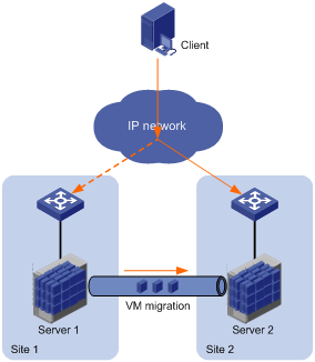
Ethernet Virtual Interconnect (EVI) is a MAC-in-IP technology that provides Layer 2 connectivity between distant Layer 2 network sites across an IP routed network. It is used for connecting geographically dispersed sites of a virtualized large-scale data center that requires Layer 2 adjacency (see Figure 1).
EVI enables long-distance virtual machine workload mobility and data mobility, disaster recovery, and business continuity. For example, virtual machines can move between data center sites without changing their IP addresses, so their movements are transparent to users and do not disrupt traffic.
Figure 1 Virtual machine migration
Layer 2 connectivity extension issues
EVI resolves the following Layer 2 connectivity extension issues:
· Site independence—EVI keeps protocol failures, such as broadcast storms, from propagating across sites.
· Transport independence—EVI has no special requirements for site location or transport network type, except that the transport network can forward IP packets.
· Link efficiency—EVI optimizes the inter-site multicast and broadcast transmission mechanism and implements load-sharing on redundant links.
· Site and transport transparency—EVI is both site and transport network transparent. It has no special site or transport network topology requirements.
· Easy management and maintenance—EVI requires deployment only on edge devices and does not introduce any topology change or configuration within sites or the transport network.
Network topologies
As shown in Figure 2, an EVI network has one edge device at each site. These sites are connected through virtual links and run the EVI IS-IS protocol to advertise their MAC address entries to each other. EVI maintains MAC routing information on the edge devices without changing the forwarding or routing information within the sites or the transport network.
Figure 2 EVI network
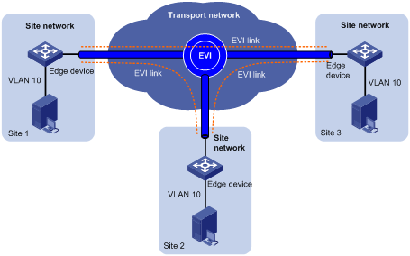
EVI supports multiple EVI networks on an edge device for extending different VLANs across the Layer 3 network. One EVI network can convey multiple VLANs, but one VLAN can map to only one EVI network. Each EVI network has separate network parameters and independently forwards traffic.
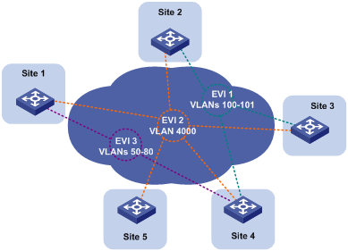
As shown in Figure 3, EVI network 1 extends VLAN 100 and VLAN 101 to Site 2, Site 3, and Site 4 for Web access traffic. EVI network 2 extends VLAN 4000 (the management VLAN) to all sites, and EVI network 3 extends VLANs 50 to 80 between Site 1 and Site 4 for database traffic.
Figure 3 Multiple EVI networks
Terminology
Edge device
An edge device performs typical Layer 2 learning and forwarding on the site-facing interfaces (internal interfaces) and performs tunneling and routing on the transport-facing interfaces.
EVI network ID
An edge device can belong to multiple EVI networks. Each EVI network is uniquely identified by a network ID.
EVI link
An EVI link is a bidirectional virtual Ethernet channel between a pair of edge devices in an EVI network. EVI links are conveyed on EVI tunnels. Each EVI link is uniquely identified by a pair of source and destination EVI tunnel IP addresses.
EVI tunnel
An EVI tunnel is a point-to-many automatic GRE tunnel that conveys EVI links for an EVI network. One EVI tunnel can provide services only for one EVI network.
EVI neighbor
All edge devices in an EVI network are EVI neighbors to one other.
ENDP
EVI Neighbor Discovery Protocol uses the client/server model to dynamically discover sites and edge devices, establish and maintain EVI links, and exchange network membership information in an EVI network.
ENDS
An EVI neighbor discovery server maintains all neighbor information in an EVI network. An EVI network can have up to two ENDSs.
ENDC
An EVI neighbor discovery client works with an ENDS to learn neighbor information and triggers EVI link setup between neighbors.
EVI IS-IS
EVI IS-IS establishes adjacencies and advertises MAC reachability information among edge devices at different sites in an EVI network.
EVI IS-IS runs independently of the Layer 3 routing protocols on the transport network and sites.
DED
An inter-site DED is elected from between the edge devices on each EVI link to send CSNP packets for LSDB synchronization.
Internal interface
Internal interfaces are site-facing Layer 2 interfaces that connect an edge device to switches or routers in the site.
Working mechanism
An edge device uses the following process to set up an EVI network and forward traffic at Layer 2 to remote sites:
1. Runs ENDP to discover EVI neighbors and set up EVI links between neighbors.
2. Runs EVI IS-IS to advertise MAC reachability information over EVI links in the EVI network.
3. Forwards traffic based on MAC reachability information that has been received from other sites.
This section describes this process in detail.
Neighbor discovery
An EVI network runs ENDP to discover all its edge devices and establishes adjacencies among the edge devices in the following process:
1. ENDS is enabled on one edge device, and ENDC is enabled on all other edge devices.
2. The ENDCs register their IP addresses and other data with the ENDS.
3. The ENDS updates its ENDC database with received data and sends the updated database to each ENDC.
4. After receiving the register reply, the ENDCs establish an EVI link with each other.
For high availability, you can configure up to two ENDSs for an EVI network.
MAC address learning
MAC reachability information on an EVI edge device comes from the following sources:
· MAC entries configured or learned in the data plane—The edge devices use the typical source-MAC-based learning mechanism to learn unicast MAC addresses in their local sites (called "local MAC addresses").
· MAC entries learned through EVI IS-IS—After completing neighbor discovery, the edge devices run EVI IS-IS in the control plane to establish adjacencies and advertise MAC reachability information that has been learned or configured in the data plane to each other over EVI links.
|
|
NOTE: The mac-address max-mac-count command and the mac-address mac-learning enable command take effect only on local MAC addresses, which are learned in the data plane. They do not take effect on remote MAC addresses, which are learned in the control plane. |
Unicast flow
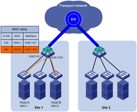
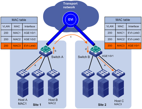
For intra-site unicast flows, an edge device performs the typical MAC address table lookup, as shown in Figure 4.
Figure 4 Layer 2 forwarding in a site
The following forwarding process (see Figure 5) takes place for unicast flows between sites:
1. The source edge device learns the source MAC address of the incoming Ethernet frame, and looks up the destination MAC address in its MAC table for the outgoing interface.
2. If the outgoing interface is an EVI-Link interface instead of a physical port, the source edge device encapsulates the frame in a GRE header, and then adds an IP header and a link layer protocol header.
In the outer IP header, the source IP address is the source edge device's tunnel source IP address, and the destination IP address is the destination edge device's tunnel source IP address.
3. The source edge device forwards the encapsulated packet out of the EVI link to the destination edge device across the IP transport network.
4. The destination edge device removes the headers of the original Ethernet frame, looks up the destination MAC address in the MAC address table, and sends the frame out of the matching outgoing interface.
Figure 5 Layer 2 forwarding between sites
Flooding flow
An edge device handles flooding by frame type, as follows:
· Broadcast frame—Floods the frame to all interfaces in the VLAN where the frame has been received, including internal interfaces and EVI-Link interfaces.
· Destination-unknown unicast or multicast frame—Floods the frame to all internal interfaces in the VLAN where the frame has been received. The edge device typically does not forward destination-unknown frames to other sites. If a site-to-site flooding is desirable for a special MAC address, use the selective flooding feature (see "Selective flooding").
To flood a frame to remote sites, an EVI edge device must replicate the frame, encapsulate each replica in one unicast frame for each destination site, and send the unicast frames to the remote edge devices.
ARP flood suppression
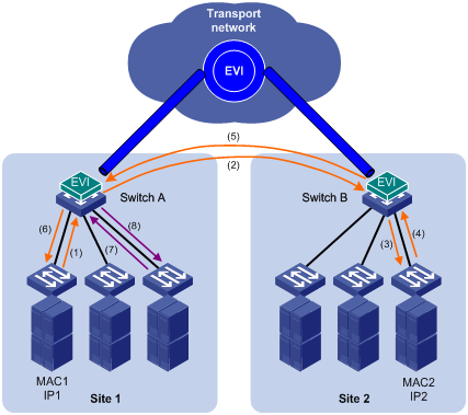
ARP flood suppression reduces ARP request broadcasts on the EVI network by enabling edge devices to reply to ARP requests on behalf of remote-site hosts.
As shown in Figure 6, this feature snoops ARP packets on an EVI tunnel interface to populate the ARP flood suppression table with remote MAC addresses. If an ARP request has a matching entry, the local edge device replies to the request on behalf of the remote-site host. If no match is found, the edge device floods the request to the EVI network.
ARP flood suppression uses the following workflow:
1. Host IP1 in site 1 sends an ARP request to obtain the MAC address of IP2.
2. Site 1's edge device floods the ARP requests out of all interfaces, including the EVI tunnel interfaces.
3. Site 2's edge device de-encapsulates the ARP request and broadcasts the request.
4. IP2 sends an ARP reply back to site 1's edge device over the EVI link.
5. Site 1's edge device creates an ARP cache entry for the remote MAC address and forwards the reply to the requesting host.
6. Site 1's edge device replies to all subsequent requests for the MAC address of IP2.
Figure 6 ARP flood suppression
Selective flooding
Selective flooding enables an edge device to send an unknown unicast or multicast frame out of an EVI tunnel interface.
This feature is designed for special multicast addresses that require flooding across sites but cannot be added to a multicast forwarding table by IGMP snooping.
For example, you must configure selective flooding for PIM hellos, IGMP general query packets, and Microsoft NLBS cluster traffic to be sent out of an EVI tunnel interface.
Path MTU
When encapsulating an Ethernet frame in EVI, the edge device does not modify the Ethernet frame, but it sets the DF bit in the IP header. For an Ethernet transport network, the total size of an EVI protocol packet increases by 46 bytes, and the total size of a data packet increases by 38 bytes. Because EVI does not support path MTU discovery, your EVI deployment must make sure the path MTU of the transport network is higher than the maximum size of EVI tunneled frames.
Licensing requirements
EVI requires a license. For information about feature licensing, see Fundamentals Configuration Guide.
Prerequisites
Before you can configure EVI, you must perform the following tasks:
1. Set the system operating mode to advanced by using the system-working-mode advance command.
2. Save the configuration.
3. Delete the binary .mdb next-startup configuration file.
4. Reboot the device.
For more information about setting the system operating mode, see device management in Fundamentals Configuration Guide.
EVI configuration task list
Perform the following tasks on all edge devices of an EVI network:
|
Tasks at a glance |
Remarks |
|
Configuring EVI basic functions: (Optional.) Configuring a site ID (Required.) Configuring an EVI tunnel: · (Required.) Assigning a network ID to the EVI tunnel · (Required.) Specifying extended VLANs on the EVI tunnel · (Required.) Configuring ENDP · (Optional.) Enabling EVI on transport-facing physical interfaces |
An EVI tunnel can provide services for only one EVI network. All edge devices in an EVI network must have the same network ID. An extended VLAN can be assigned only to one EVI network. |
|
(Optional.) Tuning EVI IS-IS parameters |
EVI IS-IS automatically runs on an EVI tunnel interface immediately after the interface is created. You can tune EVI IS-IS parameters for optimizing network performance. |
|
(Optional.) Enabling EVI ARP flood suppression |
Perform this task to reduce ARP request broadcasts on an EVI network. |
|
(Optional.) Enabling EVI flooding for all destination-unknown frames |
Perform this task to flood frames with unknown MAC addresses to the EVI tunnel interface. |
|
(Optional.) Enabling selective flooding for a MAC address |
Perform this task for special multicast MAC addresses that require Layer 2 inter-site forwarding but cannot be learned into the MAC address table. |
|
(Required.) Enabling MAC address learning at the ingress |
Perform this task to ensure correct MAC address learning. |
Configuring EVI basic functions
Except for configuring the site ID and enabling the EVI feature, all tasks in this section are required for setting up an EVI network.
Configuring a site ID
By default, all edge devices in an EVI network have a site ID of 0. To identify the site of each edge device, you can change their site IDs.
Manually assigned site IDs must be unique in the EVI network. If the edge devices at two sites are assigned the same site ID, EVI IS-IS isolates the device with the lower MAC address. The isolated device can only receive EVI IS-IS hello packets. It cannot exchange EVI IS-IS packets with its neighbors. To identify isolated devices, use the display evi isis brief command or the display evi isis peer command.
|
|
NOTE: EVI IS-IS does not perform isolation for edge devices that use the default site ID. |
To assign a site ID to the device:
|
Step |
Command |
Remarks |
|
1. Enter system view. |
system-view |
N/A |
|
2. Assign a site ID to the device. |
evi site-id site-id |
The default site ID is 0. |
Configuring an EVI tunnel
This task provides basic EVI tunnel configuration. For more information about tunnel configuration and commands, see Layer 3—IP Services Configuration Guide and Layer 3—IP Services Command Reference.
To configure an EVI tunnel:
|
Step |
Command |
Remarks |
|
1. Enter system view. |
system-view |
N/A |
|
2. Create an EVI tunnel interface and enter tunnel interface view. |
interface tunnel number mode evi |
By default, no tunnel interface exists. The endpoints of a tunnel must use the same tunnel mode. |
|
3. Specify a source IP address or interface for the tunnel. |
source { ipv4-address | interface-type interface-number } |
By default, no source IP address or source interface is specified for any tunnel. The source interface can be a Layer 3 Ethernet interface, Layer 3 aggregate interface, VLAN interface, or Layer 3 loopback interface. EVI uses the specified address or the primary IP address of the specified source interface as the source IP address of tunneled packets on the transport network. EVI networks can share a tunnel source IP address or interface. |
|
4. Configure the EVI link keepalive interval and the maximum number of keepalive transmissions. |
keepalive [ seconds [ times ] ] |
By default, a keepalive packet is sent every five seconds and the maximum number of transmissions is two. If no reply is received from the remote end on an EVI link after the maximum number of keepalive transmissions is reached, the local end considers the EVI link as having failed. |
|
5. (Optional.) Generate a GRE key for tunneled packets based on their VLAN IDs. |
gre key vlan-id |
By default, EVI tunneled packets do not contain a GRE key. The GRE key setting must be the same across an EVI network. Perform this step if any remote edge devices generate VLAN ID-based GRE keys for EVI tunneled packets. |
Assigning a network ID to the EVI tunnel
Assign the same network ID to the EVI tunnels of all edge devices in an EVI network.
On an edge device, the network ID assigned to an EVI tunnel must be unique.
To assign a network ID to an EVI tunnel:
|
Step |
Command |
Remarks |
|
1. Enter system view. |
system-view |
N/A |
|
2. Enter tunnel interface view. |
interface tunnel number [ mode evi ] |
N/A |
|
3. Specify a network ID. |
evi network-id number |
By default, no network ID is specified. |
Specifying extended VLANs on the EVI tunnel
When configuring extended VLANs, follow these guidelines:
· You can specify an extended VLAN on only one EVI tunnel.
· To avoid loops, do not assign transport-facing ports to extended VLANs.
· To avoid data breach, make sure all edge devices in an EVI network maintain the same list of extended VLANs.
To assign extended VLANs to an EVI tunnel:
|
Step |
Command |
Remarks |
|
1. Enter system view. |
system-view |
N/A |
|
2. Enter EVI tunnel interface view. |
interface tunnel number [ mode evi ] |
N/A |
|
3. Specify extended VLANs. |
evi extend-vlan vlan-list |
By default, no VLANs are specified as extended VLANs on any EVI tunnel. To specify more extended VLANs, repeat this step. |
Configuring ENDP
ENDP enables the edge devices in an EVI network to discovery each other.
Configure an edge device as an ENDS to provide registration services or as an ENDC to register with an ENDS.
Configuration guidelines
· For redundancy, you can configure up to two ENDSs on an EVI tunnel interface. These two ENDSs work independently. The failure of one ENDS does not affect the neighbor discovery and EVI link maintenance in the EVI network.
· When you enable ENDS on an EVI tunnel interface, an ENDC is automatically enabled. This ENDC uses the source address of the EVI tunnel as the ENDS address. As a result, you can use the evi neighbor-discovery client enable command to add only one ENDS address on an ENDS-enabled EVI tunnel interface.
· To guarantee that each edge device can obtain the addresses of all its EVI neighbors, make sure the ENDSs are the same across the EVI network.
· To improve security, enable ENDP authentication.
? Make sure all authentication-enabled ENDCs and ENDSs in an EVI network use the same authentication key.
? If authentication is disabled on an ENDS, all ENDCs, including authentication-enabled ENDCs, can register with the ENDS without authentication.
? If authentication is enabled on an ENDS, only authentication-enabled ENDCs that use the same authentication key as the ENDS can register with the ENDS.
Configuring the edge device as an ENDS on the EVI tunnel
|
Step |
Command |
Remarks |
|
1. Enter system view. |
system-view |
N/A |
|
2. Enter EVI tunnel interface view. |
interface tunnel number [ mode evi ] |
N/A |
|
3. Enable ENDS. |
evi neighbor-discovery server enable |
By default, ENDS is disabled. On an ENDS-enabled tunnel interface, you can use the evi neighbor-discovery client enable command to add one more ENDS, and use the evi neighbor-discovery client register-interval command to modify the ENDC registration interval. |
|
4. (Optional.) Enable ENDP authentication. |
evi neighbor-discovery authentication { cipher | simple } password |
By default, ENDP authentication is disabled. |
Configuring the edge device as an ENDC on the EVI tunnel
|
Step |
Command |
Remarks |
|
1. Enter system view. |
system-view |
N/A |
|
2. Enter EVI tunnel interface view. |
interface tunnel number [ mode evi ] |
N/A |
|
3. Configure the edge device as the ENDC of an ENDS. |
evi neighbor-discovery client enable server-ip |
By default, ENDC is disabled. If ENDS is enabled on the EVI tunnel interface, you can use this command to specify only one more ENDS. If ENDS is disabled, you can repeat this command to specify up to two ENDSs. ENDS address is the tunnel source address configured on an ENDS-enabled EVI tunnel interface. |
|
4. (Optional.) Enable ENDP authentication. |
evi neighbor-discovery authentication { cipher | simple } password |
By default, ENDP authentication is disabled. All ENDSs and ENDCs in an EVI network must use the same authentication key. |
|
5. Configure the interval at which the ENDC updates its registration with ENDSs. |
evi neighbor-discovery client register-interval time-value |
By default, an ENDC update its registration with an ENDS every 15 seconds. |
Enabling EVI on transport-facing physical interfaces
Enable EVI on all physical interfaces that provide transport network access for EVI tunnels. To avoid forwarding failure, do not enable the spanning tree feature on these interfaces.
To enable EVI on an interface:
|
Step |
Command |
Remarks |
|
1. Enter system view. |
system-view |
N/A |
|
2. Enter Layer 2 or Layer 3 Ethernet interface view. |
interface interface-type interface-number |
N/A |
|
3. Enable EVI on the interface. |
evi enable |
By default, EVI function is disabled on all interfaces. |
Tuning EVI IS-IS parameters
EVI IS-IS automatically runs on an EVI link immediately after the link is set up. You can tune EVI IS-IS parameters to optimize the protocol performance.
EVI IS-IS configuration task list
All EVI IS-IS configuration tasks are optional except the "Creating an EVI IS-IS process" and "Changing the designated site VLAN" tasks.
|
Tasks at a glance |
Remarks |
|
N/A |
|
|
N/A |
|
|
Optimizing an EVI IS-IS network: · Configuring the EVI IS-IS hello interval · Configuring the hello multiplier for calculating the adjacency hold time · Configuring the DED priority · Configuring the CSNP packet transmit interval · Configuring the minimum LSP transmit interval and the maximum number of LSPs sent at each interval |
Perform the EVI IS-IS network optimization tasks to enable fast EVI link failure detection, set appropriate MAC reachability information update interval, and control the volume of LSP and CSNP traffic on an EVI network. |
|
Perform this task to advertise a subset of MAC addresses instead of all local MAC addresses to remote sites. |
|
|
N/A |
|
|
N/A |
|
|
Perform this task for providing nonstop services. |
|
|
Increasing the maximum number of MAC entries in an LSP for an EVI IS-IS process |
Perform this task depending on the MAC address table size on the edge device. |
Creating an EVI IS-IS process
Each EVI network has one EVI IS-IS process. Before you can configure settings in EVI IS-IS process view, you must create the process.
An EVI IS-IS process is created automatically when you perform any one of the following tasks on a tunnel interface:
· Specify extended VLANs.
· Perform network optimization tasks (see "Optimizing an EVI IS-IS network") except configuring the EVI IS-IS hello interval and the maximum LSP lifetime.
The ID of an automatically created process is the same as the EVI tunnel interface number.
Alternatively, you can use the evi-isis command to create an EVI IS-IS process manually.
To delete a manually created EVI IS-IS process, you must use the undo evi-isis command.
· If EVI IS-IS settings exist on the EVI tunnel interface, the undo evi-isis command only deletes settings configured in EVI IS-IS process view.
· If no EVI IS-IS settings exist on the EVI tunnel interface, the undo evi-isis command deletes both the EVI IS-IS process and all settings configured in EVI IS-IS process view.
An automatically created EVI IS-IS process is automatically deleted when you delete all EVI IS-IS settings from the EVI tunnel interface.
To create an EVI IS-IS process or enter its view:
|
Step |
Command |
Remarks |
|
1. Enter system view. |
system-view |
N/A |
|
2. Create an EVI IS-IS process or enter EVI IS-IS process view. |
evi-isis process-id |
By default, no EVI IS-IS process is configured. The process ID you specify must be the same as the EVI tunnel interface number. The EVI IS-IS process takes effect after you configure extended VLANs on the tunnel interface. |
Changing the designated site VLAN
EVI IS-IS uses the designated site VLAN to exchange hello packets within a site. As a best practice to avoid device isolation caused by incorrect inter-site hello packet exchange, assign different designated site VLANs to EVI network sites.
This designated site VLAN must not be extended across any EVI network.
To change the designated site VLAN for EVI IS-IS:
|
Step |
Command |
Remarks |
|
1. Enter system view. |
system-view |
N/A |
|
2. Specify a designated site VLAN. |
evi designated-vlan vlan-id |
The default designated site VLAN is VLAN 1. |
Optimizing an EVI IS-IS network
Perform the tasks in this section to optimize an EVI IS-IS network for bandwidth efficiency and high performance.
Configuring the EVI IS-IS hello interval
EVI edge devices send EVI IS-IS hellos over EVI links to establish and maintain adjacencies and elect the inter-site DED on each EVI link.
Set the hello interval depending on the network convergence requirement and system resources.
· To increase the speed of network convergence, decrease the hello interval.
· To conserve resources, increase the hello interval.
|
|
NOTE: The hello interval of a DED is one-third of the hello interval set with the evi isis timer hello command. |
To configure the EVI IS-IS hello interval on an EVI tunnel interface:
|
Step |
Command |
Remarks |
|
1. Enter system view. |
system-view |
N/A |
|
2. Enter EVI tunnel interface view. |
interface tunnel number [ mode evi ] |
N/A |
|
3. Configure the EVI IS-IS hello interval. |
evi isis timer hello seconds |
The default hello interval is 10 seconds. If the edge device is a DED, its hello interval is one-third of the hello interval set with this command. |
Configuring the hello multiplier for calculating the adjacency hold time
Adjacency hold time is the amount of time that the remote edge devices can retain the adjacency with the local edge device before an adjacency update.
· If Graceful Restart is disabled, the adjacency hold time equals the EVI IS-IS hello interval multiplied by the hello multiplier.
· If Graceful Restart is enabled, the adjacency hold time equals the greater of the following values:
? The restart interval.
? The EVI IS-IS hello interval multiplied by the hello multiplier.
Edge devices send their adjacency hold time in hello packets to update the adjacencies with their neighbors. An edge device removes the adjacency with a neighbor if it does not receive a hello packet from the neighbor before the timer expires.
To configure the multiplier for calculating the adjacency hold time on an EVI tunnel interface:
|
Step |
Command |
Remarks |
|
1. Enter system view. |
system-view |
N/A |
|
2. Enter EVI tunnel interface view. |
interface tunnel number [ mode evi ] |
N/A |
|
3. Configure the multiplier for calculating the adjacency hold time. |
evi isis timer holding-multiplier value |
The default multiplier is 3. The maximum adjacency hold time is 65535 seconds. If this value is exceeded, the actual adjacency hold time is set to 65535 seconds. |
Configuring the DED priority
The edge devices on an EVI link exchange their DED priority in EVI IS-IS hello packets to elect the inter-site DED for periodic LSDB synchronization. You can use the evi isis timer csnp command to change the synchronization interval.
The edge device with higher DED priority is more likely to be elected as an inter-site DED. If two edge devices have the same DED priority, the device with the highest MAC address is elected.
To configure the DED priority of the edge device on an EVI tunnel interface:
|
Step |
Command |
Remarks |
|
1. Enter system view. |
system-view |
N/A |
|
2. Enter EVI tunnel interface view. |
interface tunnel number [ mode evi ] |
N/A |
|
3. Configure the DED priority. |
evi isis ded-priority value |
The default DED priority is 64. |
Configuring the CSNP packet transmit interval
This configuration takes effect only on DEDs.
The DEDs in an EVI network regularly send CSNP packets to advertise LSP summaries for LSDB synchronization.
To configure the CSNP packet transmit interval on a DED:
|
Step |
Command |
Remarks |
|
1. Enter system view. |
system-view |
N/A |
|
2. Enter tunnel interface view. |
interface tunnel number [ mode evi ] |
N/A |
|
3. Configure the CSNP packet transmit interval. |
evi isis timer csnp seconds |
By default, a DED sends CSNP packets every 10 seconds. |
Configuring the minimum LSP transmit interval and the maximum number of LSPs sent at each interval
The edge device generates an LSP update when any LSDB content changes. For example, an LSP update is generated when a MAC address is removed or added.
To control EVI IS-IS LSP traffic on the EVI network:
|
Step |
Command |
Remarks |
|
1. Enter system view. |
system-view |
N/A |
|
2. Enter EVI tunnel interface view. |
interface tunnel number [ mode evi ] |
N/A |
|
3. Configure the minimum LSP transmit interval and the maximum number of LSP segments sent at each interval. |
evi isis timer lsp time [ count count ] |
By default, the minimum LSP transmit interval is 100 milliseconds, and a maximum of five LSP segments can be sent at each interval. Before the minimum transmit interval is reached, the EVI tunnel interface cannot send LSP segments. |
Configuring the maximum LSP lifetime
EVI edge devices add a lifetime in each LSP they have advertised, and update LSPs regularly or when MAC reachability information changes. If an edge device does not receive an update for an LSP before the lifetime expires, the edge device removes the LSP from the LSDB and removes the MAC addresses advertised through the LSP from the data plane.
To specify the maximum lifetime of the LSPs generated by an EVI IS-IS process:
|
Step |
Command |
Remarks |
|
1. Enter system view. |
system-view |
N/A |
|
2. Enter EVI IS-IS process view. |
evi-isis process-id |
N/A |
|
3. Configure the maximum LSP lifetime. |
timer lsp-max-age seconds |
The default maximum LSP lifetime is 1200 seconds. |
Configuring the LSP refresh interval
The edge device sends LSP updates at the refresh interval to update MAC reachability information.
To change the LSP refresh interval:
|
Step |
Command |
Remarks |
|
1. Enter system view. |
system-view |
N/A |
|
2. Enter EVI IS-IS process view. |
evi-isis process-id |
N/A |
|
3. Configure the LSP refresh interval. |
timer lsp-refresh seconds |
The default LSP refresh interval is 900 seconds. The minimum LSP transmit interval and the maximum number of LSPs sent at each interval can affect the actual LSP refresh interval. To avoid unnecessary age-outs, appropriately set the LSP refresh interval and the LSP lifetime. |
Specifying a routing policy for an EVI IS-IS process
Use a routing policy to match MAC reachability information that can be advertised to the remove EVI sites. The routing policy is also called a reachability information filtering policy.
The routing policy for EVI IS-IS can only contain the following filters:
· MAC list.
· VLAN list.
For more information about configuring routing policies, see Layer 3—IP Routing Configuration Guide.
To specify a routing policy for an EVI IS-IS process:
|
Step |
Command |
Remarks |
|
1. Enter system view. |
system-view |
N/A |
|
2. Enter EVI IS-IS process view. |
evi-isis process-id |
N/A |
|
3. Specify a routing policy for the EVI IS-IS process. |
filter-policy policy-name |
By default, the EVI IS-IS process is not associated with any routing policy. |
Enabling adjacency change logging
Adjacency change logging enables an EVI IS-IS process to send a log message to the information center when an adjacency change occurs. With the information center, you can set log message filtering and output rules, including output destinations. For more information about using the information center, see Network Management and Monitoring Configuration Guide.
To enable adjacency change logging:
|
Step |
Command |
Remarks |
|
1. Enter system view. |
system-view |
N/A |
|
2. Enter EVI IS-IS process view. |
evi-isis process-id |
N/A |
|
3. Enable adjacency change logging. |
log-peer-change enable |
By default, adjacency change logging is enabled. |
Configuring SNMP notifications and context for EVI IS-IS
To report critical EVI IS-IS events to an NMS, enable SNMP notifications for EVI IS-IS. For EVI IS-IS event notifications to be sent correctly, you must also configure SNMP as described in Network Management and Monitoring Configuration Guide.
In addition to the private EVI IS-IS MIB, EVI IS-IS shares the standard IS-IS MIB with IS-IS and other protocols that use IS-IS in the control plane. For SNMP to correctly identify a protocol's management information in the standard IS-IS MIB, you must configure a unique context for each of these protocols. If a protocol supports multiple processes, you must assign a unique context to each process.
The context names must be unique among all the protocols and their processes.
Context is a method introduced to SNMPv3 for multiple instance managements. For SNMPv1/v2c, you must specify a context name as a community name for protocol identification.
To configure SNMP notifications and context for an EVI IS-IS process:
|
Step |
Command |
Remarks |
|
1. Enter system view. |
system-view |
N/A |
|
2. Enable EVI IS-IS notifications. |
snmp-agent trap enable evi-isis [ adjacency-state-change | area-mismatch | buffsize-mismatch | id-length-mismatch | link-disconnect | lsp-parse-error | lsp-size-exceeded | max-seq-exceeded | maxarea-mismatch | new-ded | own-lsp-purge | protocol-support | rejected-adjacency | skip-sequence-number | topology-change | version-skew ] * |
By default, all EVI IS-IS notifications are enabled. |
|
3. Enter EVI IS-IS process view. |
evi-isis process-id |
N/A |
|
4. Configure an SNMP context name for the EVI IS-IS process. |
snmp context-name context-name |
By default, no SNMP context name is configured for an EVI IS-IS process. |
Configuring Graceful Restart for an EVI IS-IS process
Enable Graceful Restart for the peer EVI IS-IS processes at two ends of an EVI tunnel to guarantee nonstop forwarding while the peer EVI IS-IS processes are re-establishing their adjacency after a process restart or active/standby switchover occurs.
If Graceful Restart is enabled, the adjacency hold time equals the greater of the following values:
· The restart interval.
· The EVI IS-IS hello interval multiplied by the hello multiplier.
If the edge device is a DED, its hello interval is one-third of the hello interval set by using the evi isis timer hello command.
To configure Graceful Restart for an EVI IS-IS process:
|
Step |
Command |
Remarks |
|
1. Enter system view. |
system-view |
N/A |
|
2. Enter EVI IS-IS process view. |
evi-isis process-id |
N/A |
|
3. Enable Graceful Restart. |
graceful-restart |
By default, EVI IS-IS Graceful Restart is disabled. |
|
4. Configure the restart interval. |
graceful-restart interval interval-value |
The default restart interval is 300 seconds. If the restarting EVI process fails to complete re-establishing the adjacency with the peer EVI process, the EVI link goes down. |
Increasing the maximum number of MAC entries in an LSP for an EVI IS-IS process
An EVI IS-IS process advertises all local MAC reachability information in one LSP. By default, an LSP can convey up to 55 x 210 MAC address entries.
To increase this number to accommodate all local MAC address entries, create virtual systems. Each virtual system represents an increase of 55 x 210 MAC address entries. If n virtual systems are created, the maximum number of MAC address entries in an LSP is (n+1) x 55 x 210.
To configure EVI IS-IS virtual system:
|
Step |
Command |
Remarks |
|
1. Enter system view. |
system-view |
N/A |
|
2. Enter EVI IS-IS process view. |
evi-isis process-id |
N/A |
|
3. Create an EVI IS-IS virtual system. |
virtual-system systemid |
By default, no EVI IS-IS virtual systems are created.
The virtual system ID must be unique in the EVI network. |
Enabling EVI ARP flood suppression
Configuration restrictions and guidelines
When EVI ARP flood suppression is enabled, an EVI tunnel interface must send packets that contain a VLAN ID-based GRE key to remote edge devices. For the EVI tunnel interface to generate VLAN ID-based GRE keys, you must execute the gre key vlan-id command.
Configuration prerequisites
Before you enable EVI ARP flood suppression, create VLAN interfaces for all extended VLANs of the tunnel interface.
Configuration procedure
To enable EVI ARP flood suppression:
|
Step |
Command |
Remarks |
|
1. Enter system view. |
system-view |
N/A |
|
2. Enter EVI tunnel interface view. |
interface tunnel number [ mode evi ] |
N/A |
|
3. Enable EVI ARP flood suppression. |
evi arp-suppression enable |
By default, EVI ARP flood suppression is disabled. |
|
4. Generate a GRE key for tunneled packets based on their VLAN IDs. |
gre key vlan-id |
By default, EVI tunneled packets do not contain a GRE key. |
|
5. (Optional.) Display EVI ARP flood suppression entries. |
·
In standalone mode: ·
In IRF mode: |
The display commands are available in any view. |
Enabling EVI flooding for all destination-unknown frames
By default, the device floods unknown unicast and multicast frames only to internal interfaces. EVI flooding enables the device to flood all destination-unknown frames to an EVI tunnel interface.
To enable EVI flooding for all destination-unknown frames:
|
Step |
Command |
Remarks |
|
1. Enter system view. |
system-view |
N/A |
|
2. Enter EVI tunnel interface view. |
interface tunnel number [ mode evi ] |
N/A |
|
3. Enable EVI flooding. |
evi flooding enable |
By default, EVI flooding is disabled. |
Enabling selective flooding for a MAC address
|
|
CAUTION: Do not configure selective flooding for a unicast MAC address that might be learned at an edge device's data plane. The configuration can cause packets destined for the MAC address to be dropped on remote devices after they learn the MAC address through EVI IS-IS. |
By default, the device floods unknown unicast and multicast frames only to internal interfaces.
If an application uses a special multicast address that requires flooding across sites and cannot be added to a multicast forwarding table by IGMP snooping, enable selective flooding for the multicast address.
To enable selective flooding for a MAC address:
|
Step |
Command |
Remarks |
|
1. Enter system view. |
system-view |
N/A |
|
2. Enter EVI tunnel interface view. |
interface tunnel number [ mode evi ] |
N/A |
|
3. Enable selective flooding for the MAC address in a set of VLANs. |
evi selective-flooding mac-address mac-address vlan vlan-id-list |
By default, selective flooding is disabled for all MAC addresses. |
Enabling MAC address learning at the ingress
|
|
IMPORTANT: This feature is available in Release 11xx. |
The device can learn the source MAC address of a packet when it receives the packet at the ingress or when it sends out the packet at the egress.
For the device to correctly learn the source MAC address of a packet to be tunneled by EVI, you must enable MAC address learning at the ingress. At the egress, the device learns the source MAC address from the outer Ethernet header added after EVI encapsulation. The learned source MAC address is the MAC address of the outgoing interface instead of the source MAC address in the inner Ethernet header.
To enable MAC address learning at the ingress:
|
Step |
Command |
Remarks |
|
1. Enter system view. |
system-view |
N/A |
|
2. Enable MAC address learning at the ingress. |
mac-address mac-learning ingress |
By default, the device learns MAC addresses at the egress. |
Displaying and maintaining EVI
Execute display commands in any view and reset commands in user view.
|
Task |
Command |
|
On an ENDS, display ENDS information. |
display evi neighbor-discovery server summary |
|
On an ENDS, display neighbors that have registered with the ENDS. |
display evi neighbor-discovery server member [ interface tunnel interface-number | local local-ip | remote client-ip ] |
|
On an ENDS, display ENDS statistics. |
display evi neighbor-discovery server statistics interface tunnel interface-number |
|
Display ENDC information. |
display evi neighbor-discovery client summary |
|
Display neighbors that an ENDC has learned. |
display evi neighbor-discovery client member [ interface tunnel interface-number | local local-ip | remote client-ip | server server-ip ] |
|
Display ENDC statistics. |
display evi neighbor-discovery client statistics interface tunnel interface-number |
|
Display EVI-Link interface information for an EVI tunnel. |
display evi link interface tunnel interface-number |
|
Display information about EVI-Link interfaces. |
display interface [ evi-link ] [ brief [ down ] ] display interface [ evi-link [ interface-number ] ] [ brief [ description ] ] |
|
Display brief EVI IS-IS process information. |
display evi isis brief [ process-id ] |
|
Display local MAC addresses. |
display evi isis local-mac { dynamic | static } [ interface tunnel interface-number [ vlan vlan-id ] [ count ] ] display evi isis local-mac nonadvertised [ interface tunnel interface-number [ vlan vlan-id ] [ count ] ] |
|
Display remote MAC addresses. |
display evi isis remote-mac [ interface tunnel interface-number [ vlan vlan-id ] [ count ] ] |
|
Display EVI IS-IS link state database. |
display evi isis lsdb [ local | lsp-id lspid | verbose ] * [ process-id ] |
|
Display EVI IS-IS neighbors. |
display evi isis peer [ process-id ] |
|
Display EVI IS-IS information for a tunnel interface. |
display evi isis tunnel [ tunnel-number ] |
|
Display EVI IS-IS GR state. |
display evi isis graceful-restart status [ process-id ] |
|
Display remote MAC addresses (in standalone mode). |
display evi mac-address interface tunnel interface-number [ vlan vlan-id ] [ slot slot-number ] [ count ] display evi mac-address interface tunnel interface-number mac-address mac-address vlan vlan-id [ slot slot-number ] |
|
Display remote MAC addresses (in IRF mode). |
display evi mac-address interface tunnel interface-number [ vlan vlan-id ] [ chassis chassis-number slot slot-number ] [ count ] display evi mac-address interface tunnel interface-number mac-address mac-address vlan vlan-id [ chassis chassis-number slot slot-number ] |
|
Display EVI ARP flood suppression entries (in standalone mode). |
display evi arp-suppression interface tunnel interface-number [ vlan vlan-id ] [ slot slot-number ] [ count ] |
|
Display EVI ARP flood suppression entries (in IRF mode). |
display evi arp-suppression interface tunnel interface-number [ vlan vlan-id ] [ chassis chassis-number slot slot-number ] [ count ] |
|
Clear EVI ARP flood suppression entries. |
reset evi arp-suppression interface tunnel interface-number [ vlan vlan-id ] |
|
Clear data for EVI IS-IS processes. |
reset evi isis all [ process-id ] |
EVI configuration examples
EVI network configuration example
Network requirements
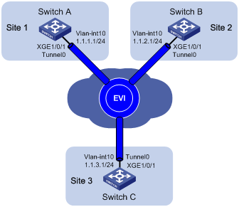
As shown in Figure 7:
· Use EVI to extend VLANs 21 through 100 across site 1, site 2, and site 3 over an IPv4 network.
· Use network ID 1 to identify the EVI network.
· Use Switch A as an ENDS and all other edge switches as ENDCs for neighbor discovery.
Configuration procedure
1. Configure routes for the sites to reach each other. (Details not shown.)
2. Configure Switch A:
# Enable MAC address learning at the ingress.
<SwitchA> system-view
[SwitchA] mac-address mac-learning ingress
# Configure the site ID.
[SwitchA] evi site-id 1
# Configure the EVI tunnel source interface (VLAN-interface 10 in this example), and assign the transport-facing physical interface Ten-GigabitEthernet 1/0/1 to the VLAN.
[SwitchA] vlan 10
[SwitchA-vlan10] port ten-gigabitethernet 1/0/1
[SwitchA-vlan10] quit
[SwitchA] interface vlan-interface 10
[SwitchA-Vlan-interface10] ip address 1.1.1.1 24
[SwitchA-Vlan-interface10] quit
# Create an IPv4 EVI tunnel interface.
[SwitchA] interface tunnel 0 mode evi
# Set the network ID of the EVI tunnel interface to 1.
[SwitchA-Tunnel0] evi network-id 1
# Specify the IP address of VLAN-interface 10 as the source IP of the EVI tunnel.
[SwitchA-Tunnel0] source 1.1.1.1
# Set the tunnel keepalive interval to 20 seconds and the maximum number of transmissions to 2.
[SwitchA-Tunnel0] keepalive 20 2
# Specify extended VLANs on the EVI tunnel interface.
[SwitchA-Tunnel0] evi extend-vlan 21 to 100
# Configure Switch A as an ENDS on the EVI tunnel interface.
[SwitchA-Tunnel0] evi neighbor-discovery server enable
[SwitchA-Tunnel0] quit
# Enable EVI on Ten-GigabitEthernet 1/0/1.
[SwitchA] interface ten-gigabitethernet 1/0/1
[SwitchA-Ten-GigabitEthernet1/0/1] evi enable
[SwitchA-Ten-GigabitEthernet1/0/1] quit
3. Configure Switch B:
# Enable MAC address learning at the ingress.
<SwitchB> system-view
[SwitchB] mac-address mac-learning ingress
# Configure the site ID.
[SwitchB] evi site-id 2
# Configure the EVI tunnel source interface (VLAN-interface 10 in this example), and assign the transport-facing physical interface Ten-GigabitEthernet 1/0/1 to the VLAN.
[SwitchB] vlan 10
[SwitchB-vlan10] port ten-gigabitethernet 1/0/1
[SwitchB-vlan10] quit
[SwitchB] interface vlan-interface 10
[SwitchB-Vlan-interface10] ip address 1.1.2.1 24
[SwitchB-Vlan-interface10] quit
# Create an IPv4 EVI tunnel interface.
[SwitchB] interface tunnel 0 mode evi
# Set the network ID of the EVI tunnel interface to 1.
[SwitchB-Tunnel0] evi network-id 1
# Specify the IP address of VLAN-interface 10 as the source IP of the EVI tunnel.
[SwitchB-Tunnel0] source 1.1.2.1
# Set the tunnel keepalive interval to 20 seconds and the maximum number of transmissions to 2.
[SwitchB-Tunnel0] keepalive 20 2
# Specify extended VLANs on the EVI tunnel interface.
[SwitchB-Tunnel0] evi extend-vlan 21 to 100
# Configure Switch B as an ENDC of Switch A.
[SwitchB-Tunnel0] evi neighbor-discovery client enable 1.1.1.1
[SwitchB-Tunnel0] quit
# Enable EVI on Ten-GigabitEthernet 1/0/1.
[SwitchB] interface ten-gigabitethernet 1/0/1
[SwitchB-Ten-GigabitEthernet1/0/1] evi enable
[SwitchB-Ten-GigabitEthernet1/0/1] quit
4. Configure Switch C:
# Enable MAC address learning at the ingress.
<SwitchC> system-view
[SwitchC] mac-address mac-learning ingress
# Configure the site ID.
[SwitchC] evi site-id 3
# Configure the EVI tunnel source interface (VLAN-interface 10 in this example), and assign the transport-facing physical interface Ten-GigabitEthernet 1/0/1 to the VLAN.
[SwitchC] vlan 10
[SwitchC-vlan10] port ten-gigabitethernet 1/0/1
[SwitchC-vlan10] quit
[SwitchC] interface vlan-interface 10
[SwitchC-Vlan-interface10] ip address 1.1.3.1 24
[SwitchC-Vlan-interface10] quit
# Create an IPv4 EVI tunnel interface.
[SwitchC] interface tunnel 0 mode evi
# Set the network ID of the EVI tunnel interface to 1.
[SwitchC-Tunnel0] evi network-id 1
# Specify the IP address of VLAN-interface 10 as the source IP of the EVI tunnel.
[SwitchC-Tunnel0] source 1.1.3.1
# Set the tunnel keepalive interval to 20 seconds and the maximum number of transmissions to 2.
[SwitchC-Tunnel0] keepalive 20 2
# Specify extended VLANs on the EVI tunnel interface.
[SwitchC-Tunnel0] evi extend-vlan 21 to 100
# Configure Switch C as an ENDC of Switch A.
[SwitchC-Tunnel0] evi neighbor-discovery client enable 1.1.1.1
[SwitchC-Tunnel0] quit
# Enable EVI on Ten-GigabitEthernet 1/0/1.
[SwitchC] interface ten-gigabitethernet 1/0/1
[SwitchC-Ten-GigabitEthernet1/0/1] evi enable
[SwitchC-Ten-GigabitEthernet1/0/1] quit
Verifying the configuration
1. Verify the configuration on Switch A:
# Display information about the EVI tunnel interface.
[SwitchA] display interface tunnel 0
Tunnel0
Current state: UP
Line protocol state: UP
Description: Tunnel0 Interface
Bandwidth: 64kbps
Maximum Transmit Unit: 64000
Internet protocol processing: disabled
Tunnel source 1.1.1.1
Tunnel keepalive enabled, Period(20 s), Retries(2)
Network ID 1
Tunnel protocol/transport GRE_EVI/IP
Last clearing of counters: Never
Last 300 seconds input rate: 0 bytes/sec, 0 bits/sec, 0 packets/sec
Last 300 seconds output rate: 0 bytes/sec, 0 bits/sec, 0 packets/sec
Input: 0 packets, 0 bytes, 0 drops
Output: 0 packets, 0 bytes, 0 drops
# Display information about EVI-Link interfaces.
[SwitchA] display evi link interface tunnel 0
Interface Status Source Destination
EVI-Link0 UP 1.1.1.1 1.1.2.1
EVI-Link1 UP 1.1.1.1 1.1.3.1
# Display ENDS information.
[SwitchA] display evi neighbor-discovery server summary
Interface Local Address Network ID Auth Members
Tunnel0 1.1.1.1 1 disabled 3
# Display ENDC information.
[SwitchA] display evi neighbor-discovery client summary
Status: I-Init E-Establish P-Probe
Interface Local Address Server Address Network ID Reg Auth Status
Tunnel0 1.1.1.1 1.1.1.1 1 15 disabled E
# Display EVI neighbors registered with the ENDS.
[SwitchA] display evi neighbor-discovery server member
Interface: Tunnel0 Network ID: 1
IP Address: 1.1.1.1
Client Address System ID Expire Created Time
1.1.1.1 000F-0001-0001 75 2014/04/01 00:00:43
1.1.2.1 000F-0001-0002 65 2014/04/01 01:00:46
1.1.3.1 000F-0001-0003 70 2014/04/01 01:02:13
# Display neighbor entries that Switch A has learned.
[SwitchA] display evi neighbor-discovery client member
Interface: Tunnel0 Network ID: 1
Local Address: 1.1.1.1
Server Address: 1.1.1.1
Neighbor System ID Created Time Expire Status
1.1.2.1 000F-0001-0002 2014/04/01 12:12:12 13 Up
1.1.3.1 000F-0001-0003 2014/04/01 12:12:12 12 Up
2. Verify the configuration on Switch B:
# Display information about the EVI tunnel interface.
[SwitchB] display interface tunnel 0
Tunnel0
Current state: UP
Line protocol state: UP
Description: Tunnel0 Interface
Bandwidth: 64kbps
Maximum Transmit Unit: 64000
Internet protocol processing: disabled
Tunnel source 1.1.2.1
Tunnel keepalive enabled, Period(20 s), Retries(2)
Network ID 1
Tunnel protocol/transport GRE_EVI/IP
Last clearing of counters: Never
Last 300 seconds input rate: 0 bytes/sec, 0 bits/sec, 0 packets/sec
Last 300 seconds output rate: 0 bytes/sec, 0 bits/sec, 0 packets/sec
Input: 0 packets, 0 bytes, 0 drops
Output: 0 packets, 0 bytes, 0 drops
# Display information about EVI-Link interfaces.
[SwitchB] display evi link interface tunnel 0
Interface Status Source Destination
EVI-Link0 UP 1.1.2.1 1.1.1.1
EVI-Link1 UP 1.1.2.1 1.1.3.1
# Display ENDC information.
[SwitchB] display evi neighbor-discovery client summary
Status: I-Init E-Establish P-Probe
Interface Local Address Server Address Network ID Reg Auth Status
Tunnel0 1.1.2.1 1.1.1.1 1 15 disabled E
# Display neighbor entries that Switch B has learned.
[SwitchB] display evi neighbor-discovery client member
Interface: Tunnel0 Network ID: 1
Local Address: 1.1.3.1
Server Address: 1.1.1.1
Neighbor System ID Created Time Expire Status
1.1.1.1 000F-0001-0001 2014/04/01 12:12:12 13 Up
1.1.3.1 000F-0001-0003 2014/04/01 12:12:12 13 Up
3. Verify the configuration on Switch C:
# Display information about the EVI tunnel interface.
[SwitchC] display interface tunnel 0
Tunnel0
Current state: UP
Line protocol state: UP
Description: Tunnel0 Interface
Bandwidth: 64kbps
Maximum Transmit Unit: 64000
Internet protocol processing: disabled
Tunnel source 1.1.3.1
Tunnel keepalive enabled, Period(20 s), Retries(2)
Network ID 1
Tunnel protocol/transport GRE_EVI/IP
Last clearing of counters: Never
Last 300 seconds input rate: 0 bytes/sec, 0 bits/sec, 0 packets/sec
Last 300 seconds output rate: 0 bytes/sec, 0 bits/sec, 0 packets/sec
Input: 0 packets, 0 bytes, 0 drops
Output: 0 packets, 0 bytes, 0 drops
# Display information about EVI-Link interfaces on Switch C.
[SwitchC] display evi link interface tunnel 0
Interface Status Source Destination
EVI-Link0 UP 1.1.3.1 1.1.1.1
EVI-Link1 UP 1.1.3.1 1.1.2.1
# Display ENDC information.
[SwitchC] display evi neighbor-discovery client summary
Status: I-Init E-Establish P-Probe
Interface Local Address Server Address Network ID Reg Auth Status
Tunnel0 1.1.3.1 1.1.1.1 1 15 disabled E
# Display neighbor entries that Switch C has learned.
[SwitchC] display evi neighbor-discovery client member
Interface: Tunnel0 Network ID: 1
Local Address: 1.1.3.1
Server Address: 1.1.1.1
Neighbor System ID Created Time Expire Status
1.1.1.1 000F-0001-0001 2014/04/01 12:12:12 13 Up
1.1.2.1 000F-0000-0002 2014/04/01 12:12:12 13 Up
4. Verify that hosts in different sites can ping one another in the same extended VLAN.
Multiple-EVI-networks configuration example
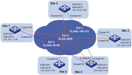
Network requirements
Use EVI to connect the sites of the data center in Figure 8. To isolate different types of traffic and extend their VLANs to different sites, set up EVI networks as shown in Table 1.
|
Traffic type |
Network ID |
Extended VLANs |
Sites |
|
Database |
1 |
100, 101 |
2, 3, 4 |
|
Network management |
2 |
4000 |
All sites |
|
Web |
3 |
50, 80 |
1, 4 |
In each EVI network, use the edge device at site 4 as an ENDS and all other edge devices as its ENDCs.
Configuration procedure
1. Configure routes for the sites to reach each other. (Details not shown.)
2. Configure site 4:
# Enable MAC address learning at the ingress.
<Site4> system-view
[Site4] mac-address mac-learning ingress
# Configure the site ID.
[Site4] evi site-id 4
# Configure the EVI tunnel source interface for all EVI tunnels, and assign the transport-facing physical interface Ten-GigabitEthernet 1/0/1 to the VLAN.
[Site4] vlan 10
[Site4-vlan10] port ten-gigabitethernet 1/0/1
[Site4-vlan10] quit
[Site4] interface vlan-interface 10
[Site4-Vlan-interface10] ip address 172.16.4.1 16
[Site4-Vlan-interface10] quit
# Configure the database EVI network.
[Site4] interface tunnel 101 mode evi
[Site4-Tunnel101] source 172.16.4.1
[Site4-Tunnel101] evi network-id 1
[Site4-Tunnel101] evi extend-vlan 100 101
[Site4-Tunnel101] evi neighbor-discovery server enable
[Site4-Tunnel101] quit
# Configure the network management EVI network.
[Site4] interface tunnel 102 mode evi
[Site4-Tunnel102] source 172.16.4.1
[Site4-Tunnel102] evi network-id 2
[Site4-Tunnel102] evi extend-vlan 4000
[Site4-Tunnel102] evi neighbor-discovery server enable
[Site4-Tunnel102] quit
# Configure the Web service EVI network.
[Site4] interface tunnel 103 mode evi
[Site4-Tunnel103] source 172.16.4.1
[Site4-Tunnel103] evi network-id 3
[Site4-Tunnel103] evi extend-vlan 50 to 80
[Site4-Tunnel103] evi neighbor-discovery server enable
[Site4-Tunnel103] quit
# Enable EVI on Ten-GigabitEthernet 1/0/1.
[Site4] interface ten-gigabitethernet 1/0/1
[Site4-Ten-GigabitEthernet1/0/1] evi enable
[Site4-Ten-GigabitEthernet1/0/1] quit
3. Configure site 1:
# Enable MAC address learning at the ingress.
<Site1> system-view
[Site1] mac-address mac-learning ingress
# Configure the site ID.
[Site1] evi site-id 1
# Configure the EVI tunnel source interface for all EVI tunnels, and assign the transport-facing physical interface Ten-GigabitEthernet 1/0/1 to the VLAN.
[Site1] vlan 10
[Site1-vlan10] port ten-gigabitethernet 1/0/1
[Site1-vlan10] quit
[Site1] interface vlan-interface 10
[Site1-Vlan-interface10] ip address 172.16.1.1 16
[Site1-Vlan-interface10] quit
# Configure the network management EVI network.
[Site1] interface tunnel 102 mode evi
[Site1-Tunnel102] source 172.16.1.1
[Site1-Tunnel102] evi network-id 2
[Site1-Tunnel102] evi extend-vlan 4000
[Site1-Tunnel102] evi neighbor-discovery client enable 172.16.4.1
[Site1-Tunnel102] quit
# Configure the Web service EVI network.
[Site1] interface tunnel 103 mode evi
[Site1-Tunnel103] source 172.16.1.1
[Site1-Tunnel103] evi network-id 3
[Site1-Tunnel103] evi extend-vlan 50 to 80
[Site1-Tunnel103] evi neighbor-discovery client enable 172.16.4.1
[Site1-Tunnel103] quit
# Enable EVI on Ten-GigabitEthernet 1/0/1.
[Site1] interface ten-gigabitethernet 1/0/1
[Site1-Ten-GigabitEthernet1/0/1] evi enable
[Site1-Ten-GigabitEthernet1/0/1] quit
4. Configure all the other sites in the same way that site 1 is configured. Make sure extended VLANs are correctly configured at each site.
Verifying the configuration
# Display neighbors registered with the ENDS in each EVI network.
[Site4] display evi neighbor-discovery server member
Interface: Tunnel101 Network ID: 1
IP Address: 172.16.4.1
Client Address System ID Expire Created Time
172.16.2.1 000F-0001-0002 75 2014/04/01 00:00:43
172.16.3.1 000F-0001-0003 65 2014/04/01 01:00:46
172.16.4.1 000F-0001-0004 20 2014/04/01 01:02:13
Interface: Tunnel102 Network ID: 2
IP Address: 172.16.4.1
Client Address System ID Expire Created Time
172.16.1.1 000F-0001-0001 19 2014/04/01 00:19:31
172.16.2.1 000F-0001-0002 25 2014/04/01 00:00:43
172.16.3.1 000F-0001-0003 15 2014/04/01 01:00:46
172.16.4.1 000F-0001-0004 20 2014/04/01 01:02:13
172.16.5.1 000F-0001-0005 18 2014/04/01 01:04:32
Interface: Tunnel103 Network ID: 3
IP Address: 172.16.4.1
Client Address System ID Expire Created Time
172.16.1.1 000F-0001-0001 19 2014/04/01 00:19:31
172.16.4.1 000F-0001-0004 20 2014/04/01 01:02:13