- Table of Contents
- Related Documents
-
| Title | Size | Download |
|---|---|---|
| 01-Text | 12.30 MB |
Contents
2 Configuring basic BIOS settings
Entering the BIOS setup utility
Displaying processor information
Displaying onboard drive information
Displaying HDM network information
Setting HDM network information
Configuring the BIOS passwords
Setting the administrator password
Setting the system date and time
Restoring BIOS default settings
Intel(R) Virtual RAID on CPU submenu
Serial Port Console Redirection submenu
PCI Subsystem Settings submenu
Network Stack Configuration submenu
Miscellaneous Configuration submenu
Server ME Configuration submenu
Processor Configuration submenu
Common RefCode Configuration submenu
Advanced Power Management Configuration submenu
4 Mapping relations of PCH SATA/sSATA ports and drive backplane ports
1 BIOS overview
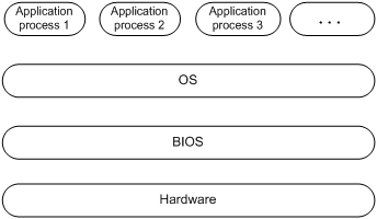
Basic Input and Output System (BIOS) is a non-volatile firmware stored in the system ROM of a server. It is used to perform hardware initialization during server booting and provide runtime services for the operating systems. As shown in Figure 1-1, the BIOS interacts between the server hardware and the operating system (OS).
Figure 1-1 Layered architecture of a server system
This document is applicable to the following products:
· H3C UniServer R4900 G3.
· H3C UniServer R4700 G3.
· H3C UniServer R2900 G3.
· H3C UniServer R2700 G3.
|
|
NOTE: · The information in this document is subject to change over time. For the most up-to-date information, contact H3C Support. · You can access the H3C website to obtain the most recent version of the BIOS. |
2 Configuring basic BIOS settings
This section provides procedures for the following tasks:
· Entering the BIOS setup utility.
· Displaying processor information.
· Displaying memory information.
· Displaying onboard drive information.
· Displaying HDM network information.
· Setting HDM network information.
· Configuring the BIOS passwords.
· Setting the system date and time.
· Setting the server boot order.
· Restoring BIOS default settings.
Entering the BIOS setup utility
1. Connect a keyboard, mouse, and monitor to the server or enable the remote console from the HDM Web interface.
For information about enabling the remote console, see HDM online help.
2. Start or restart the server.
3. Enter the BIOS password if required during boot-up, as shown in Figure 2-1.
By default, no BIOS passwords are set. For information about BIOS password setup, see "Configuring the BIOS passwords."
|
|
NOTE: · If you enter an incorrect password for three consecutive times, the server will restart automatically. · To clear BIOS password settings, power off the server, jump pins 2 and 3 of system maintenance switch 2 on the server's system board, and then power on the server. For more information about the location of the system maintenance switch, see the user guide for the server. |
Figure 2-1 Entering the BIOS password

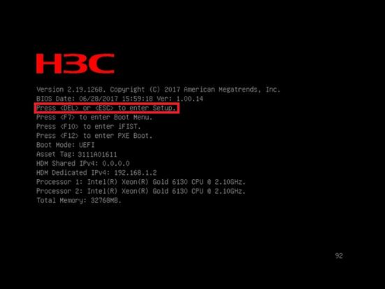
4. Press Del or Esc when the BIOS startup screen opens, as shown in Figure 2-2.
Figure 2-2 BIOS startup screen
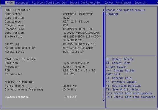
5. On the BIOS setup utility screen that opens, follow the instructions at the lower-right side of the screen to configure BIOS settings, as shown in Figure 2-3.
Table 2-1 shows detailed information about the operation keys.
Figure 2-3 BIOS setup utility screen

|
Key |
Description |
|
→← |
Select a screen. |
|
↑↓ |
Select an item or a submenu. |
|
Enter |
Select an item to edit its value or access a submenu. |
|
+/- |
Change the field value of the selected item. |
|
ESC |
Exit the BIOS setup utility or return to the previous screen. |
|
F1 |
Display the general help window. |
|
F2 |
Load previous values in BIOS. |
|
F3 |
Load default values in BIOS. |
|
F4 |
Save the current configuration and exit BIOS. |
|
<K> |
Scroll up the help area at the upper-right side of the screen. |
|
<M> |
Scroll down the help area at the upper-right side of the screen. |
Displaying processor information
1. Enter the BIOS setup utility. For more information, see "Entering the BIOS setup utility."
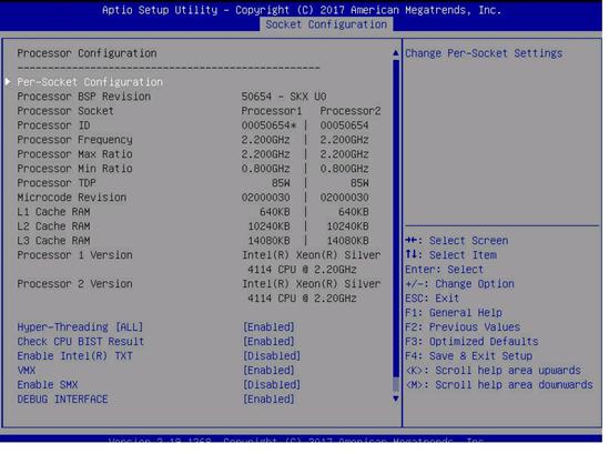
2. Select Socket Configuration > Processor Configuration, and press Enter.
The Processor Configuration submenu that opens displays detailed information about processors, as shown in Figure 2-4.
For more information about the Processor Configuration submenu, see "Processor Configuration submenu."
Figure 2-4 Processor Configuration screen
Displaying memory information
1. Enter the BIOS setup utility. For more information, see "Entering the BIOS setup utility."
2. Select Socket Configuration > Memory Configuration, and press Enter.
The Memory Configuration submenu that opens displays memory capacity and frequency information, as shown in Figure 2-5.
For more information about the Memory Configuration submenu, see "Memory Configuration submenu."
Figure 2-5 Memory Configuration submenu
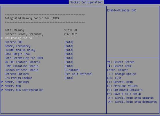
3. Select Memory Topology, and press Enter.
The screen that opens displays detailed information about each DIMM.
Displaying onboard drive information
Both the PCH SATA Configuration and PCH sSATA Configuration submenus display onboard drive information. This example uses the PCH SATA Configuration submenu. For more information about the submenus, see "PCH Configuration submenu."
To display drive information:
1. Enter the BIOS setup utility. For more information, see "Entering the BIOS setup utility."
2. Select Platform Configuration > PCH Configuration > PCH SATA Configuration, and press Enter.
The PCH SATA Configuration submenu that opens displays drive information, as shown in Figure 2-6.
Figure 2-6 PCH SATA Configuration submenu

Displaying HDM network information
1. Enter the BIOS setup utility. For more information, see "Entering the BIOS setup utility."
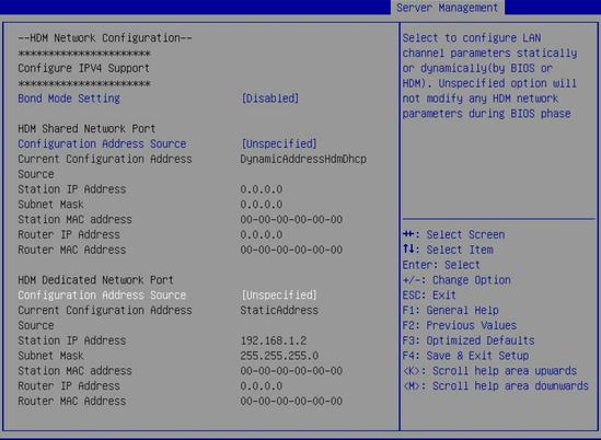
2. Select Server Management > HDM Network Configuration, and press Enter.
The HDM Network Configuration submenu that opens displays HDM network configuration information, as shown in Figure 2-7.
Figure 2-7 HDM Network Configuration screen

Setting HDM network information
Perform this task to configure the IP address, subnet mask, and router IP address of HDM network ports and the method of obtaining the network information.
Restrictions and guidelines
The HDM Network Configuration submenu content varies by bond mode setting.
· Enabled—Displays network information about the HDM bonding network port.
· Disabled—Displays network information about the HDM shared network port and HDM dedicated network port.
To avoid network storms, make sure the IP address of the HDM shared network port is on a network segment different than the HDM dedicated network port.
The submenu items are the same for all HDM network ports.
Procedure
This example describes how to set network information for the HDM shared network port and HDM dedicated network port.
To set HDM network information:
1. Enter the BIOS setup utility. For more information, see "Entering the BIOS setup utility."
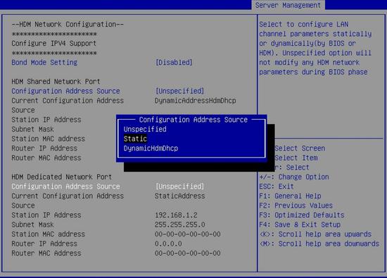
2. Select Server Management > HDM Network Configuration, and press Enter.
The HDM Network Configuration submenu that opens displays HDM network configuration information, as shown in Figure 2-8.
Figure 2-8 HDM Network Configuration submenu
3. Select Configuration Address Source for the HDM shared network port or the HDM dedicated network port. Then, press Enter.
4. In the dialog box that opens, select the method for obtaining HDM network information. Options are:
¡ Unspecified—Retains current configuration.
¡ Static—Uses manually specified configuration.
¡ DynamicHdmDhcp—Uses network information obtained through DHCP.
Figure 2-9 Configuration Address Source dialog box
5. Press Enter. If you select Static as the method for obtaining HDM network information, edit the following items and press Enter every time you finish editing:
¡ Station IP Address—Enter a static IP address. This item is required.
¡ Subnet Mask—Enter a subnet mask for the static IP address. This item is required.
¡ Router IP Address—Enter a gateway IP address.
¡ Router MAC Address—Enter a gateway MAC address.
6. Press F4 to save the configuration.
The server will restart automatically.
Configuring the BIOS passwords
BIOS passwords include an administrator password and a user password. By default, no passwords are set. The system prompts for a password at user login and grants user or administrator privileges to the login user according to the entered password.
Restrictions and guidelines
To prevent unauthorized access and changes to the BIOS settings, set different BIOS user and BIOS administrator passwords for the server.
When you change a BIOS password, make sure the new password is different from the most recent three passwords.
The BIOS passwords must meet the following requirements:
· A case-sensitive string of 8 to 20 characters. Valid characters are letters, digits, spaces, and special characters in Table 2-2.
· Contain a minimum of two character types from uppercase letters, lowercase letters, and digits.
· Contain a minimum of one space or special character.
|
Character name |
Symbol |
Character name |
Symbol |
|
Back quote |
` |
Tilde |
~ |
|
Exclamation point |
! |
At sign |
@ |
|
Pound sign |
# |
Dollar sign |
$ |
|
Percent sign |
% |
Caret |
^ |
|
Ampersand sign |
& |
Asterisk |
* |
|
Left parenthesis |
( |
Right parenthesis |
) |
|
Underscore |
_ |
Plus sign |
+ |
|
Minus sign |
- |
Equal sign |
= |
|
Left bracket |
[ |
Right bracket |
] |
|
Back slash |
\ |
Left brace |
{ |
|
Right brace |
} |
Vertical bar |
| |
|
Semi-colon |
; |
Apostrophe |
' |
|
Colon |
: |
Quotation marks |
" |
|
Comma |
, |
Dot |
. |
|
Forward slash |
/ |
Left angle bracket |
< |
|
Right angle bracket |
> |
Question mark |
? |
Setting the administrator password
1. Enter the BIOS setup utility. For more information, see "Entering the BIOS setup utility."
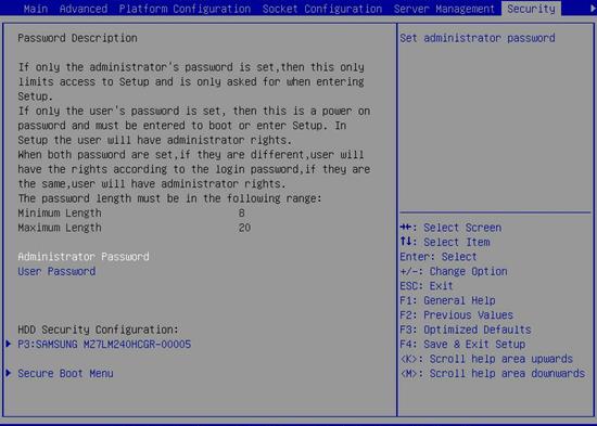
2. Select Security > Administrator Password, and press Enter.
Figure 2-10 Setting the administrator password
3. In the Create New Password dialog box that opens, enter an administrator password, and press Enter.
Figure 2-11 Creating an administrator password

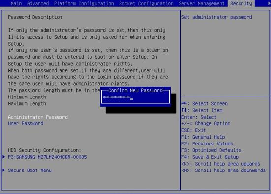
4. In the Confirm New Password dialog box that opens, enter the password again, and press Enter.
Figure 2-12 Confirming the administrator password
5. Press F4 to save the configuration.
The server will restart automatically.
Setting the user password
1. Enter the BIOS setup utility. For more information, see "Entering the BIOS setup utility."
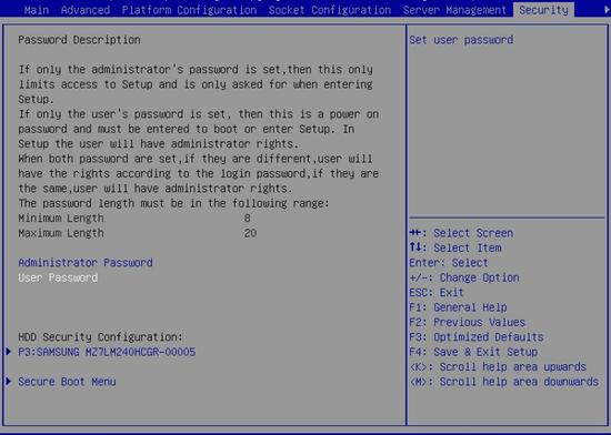
2. Select Security > User Password, and press Enter.
Figure 2-13 Setting the user password
3. In the Create New Password dialog box that opens, enter a user password, and press Enter.
Figure 2-14 Creating a user password

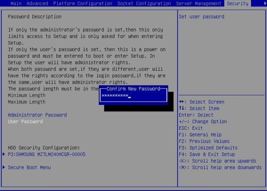
4. In the Confirm New Password dialog box that opens, enter the password again, and press Enter.
Figure 2-15 Confirming the user password
5. Press F4 to save the configuration.
The server will restart automatically.
Deleting BIOS passwords
The procedure for deleting the administrator password and user password is the same. This section uses the administrator password as an example.
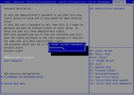
To delete the administrator password:
1. Enter the BIOS setup utility. For more information, see "Entering the BIOS setup utility."
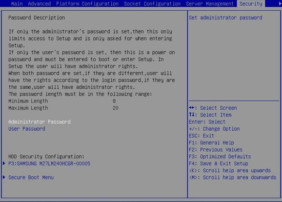
2. Select Security > Administrator Password, and press Enter.
Figure 2-16 Selecting the administrator password
3. In the Enter Current Password dialog box that opens, enter the current administrator password, and press Enter.
Figure 2-17 Entering the current administrator password
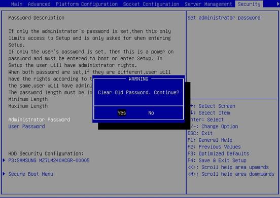
4. Press Enter when the Create New Password dialog box opens as shown in Figure 2-18.
Figure 2-18 Deleting the administrator password

5. In the WARNING dialog box that opens, select Yes, and press Enter.
Figure 2-19 Confirming the deletion
6. Press F4 to save the configuration.
The server will restart automatically.
Setting the system date and time
1. Enter the BIOS setup utility. For more information, see "Entering the BIOS setup utility."
2. Select the Main menu.
Figure 2-20 Main menu
a. Select System Date.
The system date is in the format of mm/dd/yyyy.
b. Press Enter to switch among the month, day, and year fields and use the following methods to modify the value:
- Press + to increase the value by 1.
- Press – to decrease the value by 1.
- Press numeric keys to enter a new value.
a. Select System Time.
The system time uses the 24-hour time system and is in the format of hh:mm:ss.
b. Press Enter to switch among the hour, minute, and second fields and use the following methods to modify the value:
- Press + to increase the value by 1.
- Press – to decrease the value by 1.
- Press numeric keys to enter a new value.
5. Press F4 to save the configuration.
The server will restart automatically.
Setting the BIOS boot mode
About BIOS boot modes
The server supports two BIOS boot modes: legacy mode and UEFI mode.
By default, the boot mode is UEFI. For operating systems that support only the legacy mode, change the boot mode to legacy.
Procedure
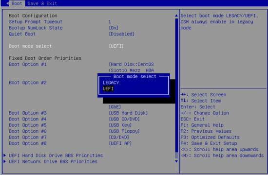
1. Enter the BIOS setup screen. For more information, see "Entering the BIOS setup utility."
2. Select Boot > Boot mode select, and press Enter.
3. In the Boot mode select dialog box that opens, select LEGACY or UEFI, and press Enter.
Figure 2-21 Setting the BIOS boot mode
4. Press F4 to save the configuration.
The server will restart automatically.
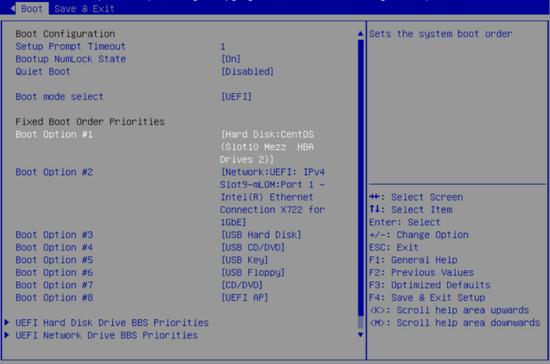
Setting the server boot order
Restrictions and guidelines
If the server has more than one boot devices of the same type, the Fixed Boot Order Priorities list displays only the first boot device. To change the first boot device, select the corresponding priorities submenu below the Fixed Boot Order Priorities list in the Boot screen.
Procedure
1. Enter the BIOS setup utility. For more information, see "Entering the BIOS setup utility."
2. Select the Boot menu.
The Fixed Boot Order Priorities list shows the order in which the server attempts to boot from boot devices. The default boot order is hard disk > network > USB hard disk > USB CD/DVD > USB key > USB floppy > CD/DVD > UEFI AP as shown in Figure 2-22.
Figure 2-22 Boot menu
|
|
NOTE: The UEFI AP is the embedded UEFI Shell. This option is displayed only when the UEFI boot mode is used. By default, UEFI Shell is disabled. To enable UEFI Shell, select UEFI Application Boot Priorities, and then select UEFI: Built-in EFI Shell. |
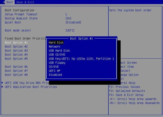
3. Select the option to be modified from the Fixed Boot Order Priorities area, and press Enter.
4. In the dialog box that opens, select a new boot device type, and press Enter.
Figure 2-23 Changing a boot option
5. Press F4 to save the configuration.
The server will restart automatically.
Configuring RAID
For information about RAID configuration, see the storage controller user guide for the server.
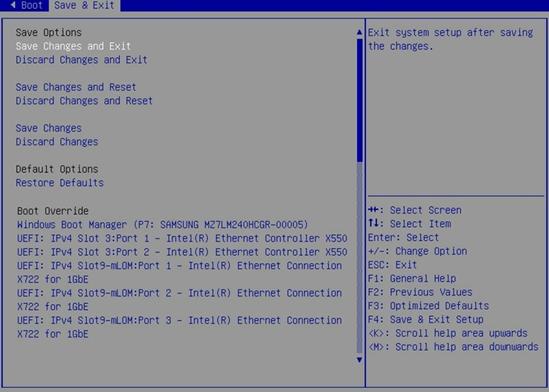
Restoring BIOS default settings
1. Enter the BIOS setup utility. For more information, see "Entering the BIOS setup utility."
2. Press F3 in the BIOS, or select Save & Exit > Restore Defaults and press Enter as shown in Figure 2-24.
Figure 2-24 Restoring the default from the Save & Exit menu
3 BIOS menus
Main menu
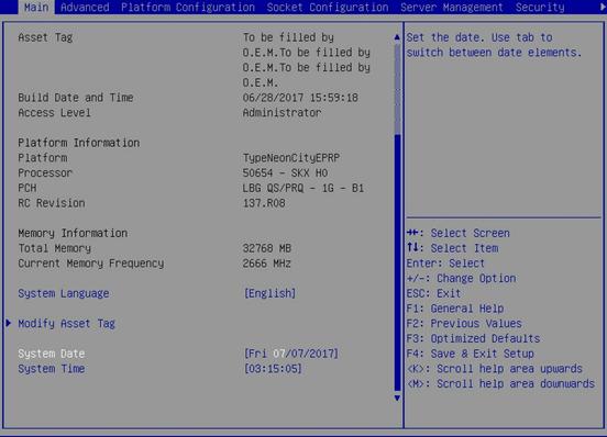
As shown in Figure 3-1, the Main menu contains information about the BIOS, memory, system language, and system time and date. For more information about the menu items, see Table 3-1.
Figure 3-1 Main menu screen
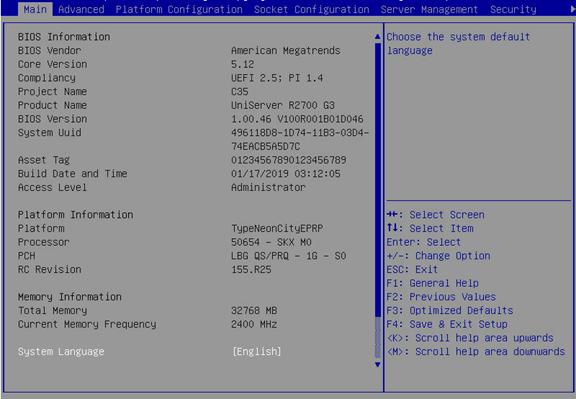
Table 3-1 Items on the Main menu screen
|
Item |
Description |
Default |
|
|
BIOS Information |
|||
|
BIOS Vendor |
Displays the BIOS vendor. |
N/A |
|
|
Core Version |
Displays the BIOS core version. |
N/A |
|
|
Compliancy |
Displays the standard with which the BIOS is compliant. |
N/A |
|
|
Project Name |
Displays the project name. |
N/A |
|
|
Product Name |
Displays the server model. |
N/A |
|
|
BIOS Version |
Displays the BIOS version. |
N/A |
|
|
System Uuid |
Displays the universally unique identifier (UUID) of the system. |
N/A |
|
|
Asset Tag |
Displays the asset tag of the server. |
N/A |
|
|
Build Date and Time |
Displays the date and time of the BIOS build. |
N/A |
|
|
Access Level |
Displays the current user's access level, Administrator or User. For more information about BIOS access levels, see "Security menu." |
N/A |
|
|
Platform Information |
|||
|
Platform |
Displays the platform type. |
N/A |
|
|
Processor |
Displays the CPU model. |
N/A |
|
|
PCH |
Displays the platform controller hub (PCH) model. |
N/A |
|
|
RC Revision |
Displays the RC version. |
N/A |
|
|
Memory Information |
|||
|
Total Memory |
Displays the total memory capacity of the system. |
N/A |
|
|
Current Memory Frequency |
Displays the current memory frequency. For information about changing the memory frequency, see "Memory Configuration submenu." |
N/A |
|
|
Other items |
|||
|
System Language |
Displays the language used in the system. The BIOS supports English and simplified Chinese. To switch between the languages, press Enter. |
English |
|
|
Modify Asset Tag |
Modify the asset tag of the server, as shown in Figure 3-2. |
N/A |
|
|
System Date |
Displays the system date. You can change the system date as needed. The system date is in the format of mm/dd/yyyy. To move between the month, day, and year fields, press Enter. To change the value for the selected field, use the following method: · Press + to increase the value by 1. · Press - to decrease the value by 1. · Press a numeric key to set the final value. |
N/A |
|
|
System Time |
Displays the system time. You can change the system time as needed. The system time is in the format of hh:mm:ss in 24-hour format. To move between the hour, minute, and second fields, press Enter. To change the value for the selected field, use the following method: · Press + to increase the value by 1. · Press - to decrease the value by 1. · Press a numeric key to set the final value. |
N/A |
|
Figure 3-2 shows the Modify Asset Tag submenu, on which you can configure the asset tag of the server as described in Table 3-2.
Figure 3-2 Modify asset tag submenu screen
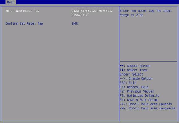
Table 3-2 Items on the Modify Asset Tag submenu screen
|
Description |
|
|
Enter New Asset Tag |
Enter a new asset tag. |
|
Confirm Set Asset Tag |
Select NO to cancel the tag change. Select YES to save the tag change. |
Advanced menu
The Advanced menu varies by server configuration.
· If no Ethernet interfaces, storage controllers, or NVMe drives that have an Option ROM are present, the Advanced menu is displayed as shown in Figure 3-3.
· If Ethernet interfaces, storage controllers, or NVMe drives that have an Option ROM are present, the Advanced menu is displayed as shown in Figure 3-4.
The Advanced menu contains advanced system features and functionalities, which are described in Table 3-3.
Figure 3-3 Advanced menu screen (without Option ROM-capable Ethernet interfaces, storage controllers, or NVMe drives)
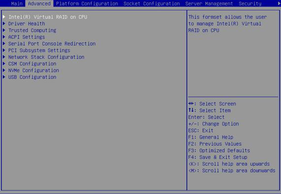
Figure 3-4 Advanced menu screen (with Option ROM-capable Ethernet interfaces, storage controllers, or NVMe drives)
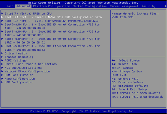
Table 3-3 Items on the Advanced menu screen
|
Item |
Description |
|
Intel(R) Virtual RAID on CPU |
Submenu for configuring Intel(R) Virtual RAID on CPU (Intel VROC). |
|
Slot x:Port x |
Submenu for configuring an Ethernet interface, storage controller, or NVMe drive that has an Option ROM. |
|
Driver Health |
Submenu for viewing the health state of drivers or controllers. This submenu is available only in UEFI boot mode. |
|
Trusted Computing |
Submenu for configuring trusted computing. |
|
ACPI Settings |
Submenu for configuring advanced configuration and power interface (ACPI) settings. |
|
Submenu for configuring serial console port redirection. |
|
|
PCI Subsystem Settings |
Submenu for configuring the PCI subsystem. |
|
Network Stack Configuration |
Submenu for configuring network stacks. This submenu is available only in UEFI boot mode. |
|
CSM Configuration |
Submenu for configuring the compatibility support module (CSM). |
|
NVMe Configuration |
Submenu for configuring NVMe. |
|
USB Configuration |
Submenu for configuring USB. |
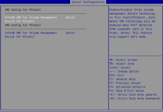
Intel(R) Virtual RAID on CPU submenu
Intel® Virtual RAID on CPU (Intel VROC) is a RAID solution specifically designed for NVMe-based SSDs.
Prerequisites for using Intel VROC
Before using Intel VROC for RAID volume management on a CPU that has NVMe SSDs attached, use the following procedure to enable Intel Volume Management Device (VMD) for that CPU:
1. Install an Intel NVMe VROC module. The system supports the following NVMe VROC modules:
¡ Intel® VROC Standard—Supports RAID levels 0, 1, and 10.
¡ Intel® VROC Premium—Supports RAID levels 0, 1, 5, and 10.
¡ Intel® VROC Intel® SSD Only—Supports RAID levels 0, 1, 5, and 10 and only Intel NVMe SSDs.
2. Make sure a 4-port NVMe expander module (Retimer) or 8-port NVMe expander module (Switch) is installed in the PCIe X16 slot for that CPU.
3. Enable Intel Volume Management Device (VMD) for that CPU:
a. Select Socket Configuration > IIO Configuration > Intel® VMD technology, and then press Enter.
b. On the Intel® VMD technology menu, select the CPU for which you want to enable Intel VMD, and then press Enter. This example uses Intel® VMD for Volume Management Device on Processor 1.
c. On the VMD Config for PStack0 screen shown in Figure 3-5, set the status of Intel® VMD for Volume Management Device for PStack0 to Enabled or Auto.
Figure 3-5 Intel® VMD for Volume Management Device on Processor 1 screen
Using the Intel Virtual RAID on CPU menu to manage volumes or VMD controllers
Figure 3-6 shows the Intel(R) Virtual RAID on CPU menu, on which you can manage RAID volumes and Intel VMD controllers as described in Table 3-4.
Figure 3-6 Intel(R) Virtual RAID on CPU menu screen
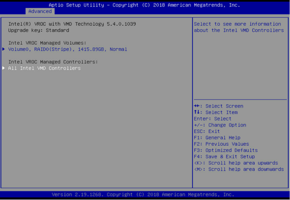
Table 3-4 Items on the Intel(R) Virtual RAID on CPU menu screen
|
Item |
Description |
|
Intel VROC Managed Volumes |
Displays summary information about managed RAID volumes, including their volume name, RAID level, capacity, and state, for example, Volume0, RAID0 (Stripe), 1415.89GB, Normal. To view detailed information about a volume or manage its member drives, select that volume. The RAID volume management submenu opens, as shown in Figure 3-7. For more information about the submenu items, see Table 3-5. |
|
Intel VROC Managed Controllers |
To view information about Intel VROC managed VMD controllers and use a controller to create and configure a RAID volume, select All Intel VMD Controllers. The Intel VMD controller management submenu opens, as shown in Figure 3-11. For more information about the submenu items, see Table 3-7. |
Managing an Intel VROC volume
Figure 3-7 shows the RAID volume management submenu screen, on which you can view information about the selected RAID volume and manage its member drives. For more information about the submenu items, see Table 3-5.
Figure 3-7 RAID volume management submenu screen
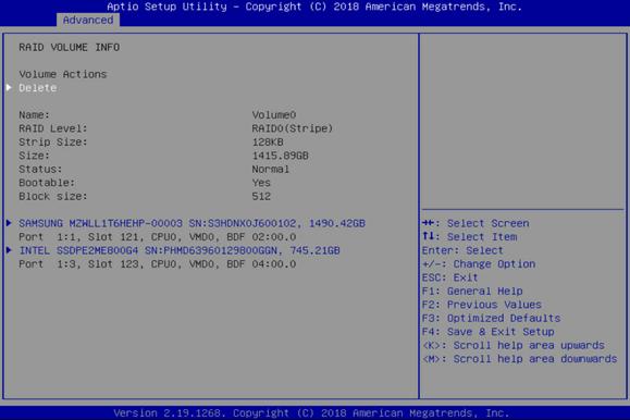
Table 3-5 Items on the RAID volume management submenu screen
|
Item |
Description |
|
Volume Actions |
|
|
Delete |
All data in the member drives of the volume are permanently deleted when the volume is deleted. As a best practice to avoid data loss, back up the data before you delete a volume. To delete the RAID volume, select this item, and then select Yes to confirm the deletion, as shown in Figure 3-8. |
|
RAID Volume Information |
|
|
Name |
Displays the name of the RAID volume. |
|
RAID Level |
Displays the RAID level. |
|
Strip Size |
Displays the stripe size of the RAID volume. |
|
Size |
Displays the capacity of the RAID volume. |
|
Status |
Displays the state of the RAID volume. |
|
Bootable |
Displays whether the RAID volume is bootable. |
|
Block Size |
Displays the block size of the RAID volume, in bytes. |
|
RAID Member Disks |
|
|
Member drives of the RAID, for example: · SAMSUNG MZWLL1T6HEHP-00003 SN:S3HDNX0J600102,1490.42GB Port 1:1,Slot 121,CPU0,VMD0,BDF 02:00.0 · INTEL SSDPE2ME800G4 SN:PHMD63960129800GGN,745.21GB Port 1:3,Slot 123,CPU0,VMD0,BDF 04:00.0 |
To manage a member drive or view its detailed information, select that drive. The RAID member drive management submenu opens, as shown in Figure 3-9. For more information about the submenu items, see Table 3-6. The port ID depends on the installed NVMe SSD expander module and its installation location: · If a 4-port NVMe SSD expander module is installed in the riser card on PCIe riser connector 1, the port ID is 1:1 or 1:3 as shown in the example. · If an 8-port NVMe SSD expander module is installed, the port ID is 1:0 or 2:0. If the expander module is installed in the riser card on PCIe riser connector 1, the port ID is 1:0. If the expander module is installed in the riser card on PCIe riser connector 2, the port ID is 2:0. |
Figure 3-8 RAID volume delete screen
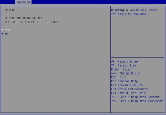
Figure 3-9 RAID member drive management submenu screen
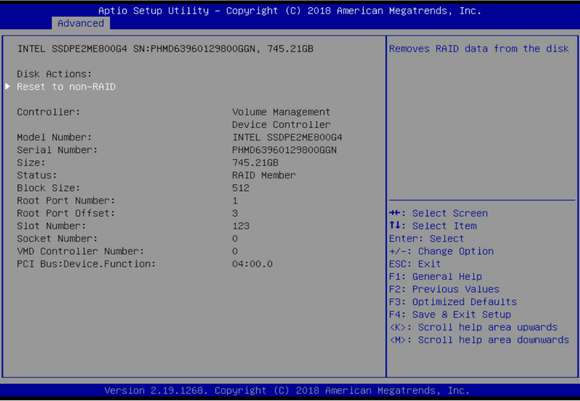
Table 3-6 Items on the RAID member drive management submenu screen
|
Item |
Description |
|
Disk Actions |
|
|
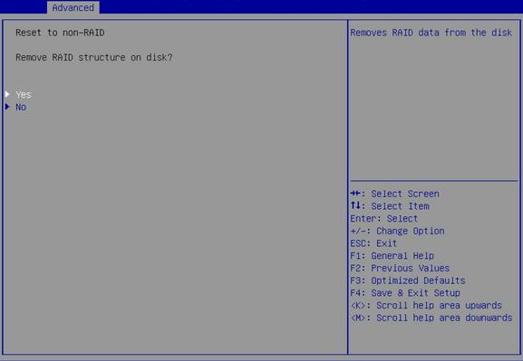
Reset to non-RAID |
This action deletes all data on the drive. As a best practice to avoid data loss, back up the data before you perform this action. To remove the drive from the RAID array, select this item, and then select Yes to confirm the deletion, as shown in Figure 3-10. |
|
Other information |
|
|
Controller |
Displays the controller information, which is Volume Management Device Controller in this example. |
|
Model Number |
Displays the model number of the drive. |
|
Serial Number |
Displays the serial number of the drive. |
|
Size |
Displays the capacity of the drive. |
|
Status |
Displays whether the drive is a RAID member. |
|
Block Size |
Displays the block size of the drive, in bytes. |
|
Root Port Number |
Displays the root port number of the drive. |
|
Root Port Offset |
Displays the root port offset of the drive. |
|
Slot Number |
Displays the slot number of the drive. |
|
Socket Number |
Displays the slot number of the processor for the drive. |
|
VMD Controller Number |
Displays controller number. |
|
PCI Bus:Device.Function |
Displays the Bus:Dev:Func of the drive. |
Figure 3-10 shows the Reset to non-RAID screen, on which you can remove the selected drive from the RAID array.
Figure 3-10 Reset to non-RAID screen
Managing an Intel VMD controller
Figure 3-11 shows the Intel VMD controller management submenu screen, on which you can perform the following tasks:
· Create a RAID volume by using non-RAID physical drives. A non-RAID physical drives is a drive that has not been used to build a RAID volume.
· View information about a non-RAID physical drive or set that drive as a spare or journal disk.
For more information about the submenu items, see Table 3-7.
Figure 3-11 Intel VDM controller management submenu screen
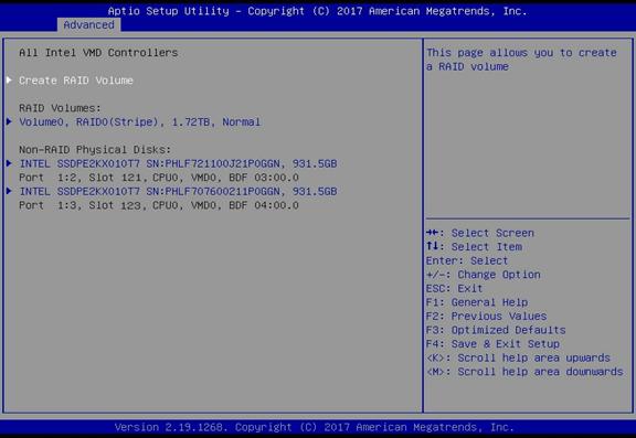
Table 3-7 Items on the Intel VMD controller management submenu screen
|
Item |
Description |
|
Create RAID Volume |
To create a RAID volume, select this item to access the Create RAID Volume screen shown in Figure 3-12 , and then create the RAID volume as described in Table 3-8. |
|
RAID Volumes |
|
|
Existing RAID volumes, for example: Volume0, RAID0 (Stripe), 1.72TB, Normal |
Displays summary information about each existing RAID volume, including the volume name, RAID level, capacity, and state. |
|
Non-RAID Physical Disks |
|
|
Drives that are not in a RAID volume, for example: INTEL SSDPE2KX010T7 SN:PHLF721100J21P0GGN,931.5GB Port 1:2,Slot 121,CPU0,VMD0,BDF 03:00.0 |
Displays physical drives that are available for creating a RAID volume. To view information about a non-RAID physical drive or set that drive as a spare or journal disk, select that drive to access the non-RAID physical drive configuration submenu shown in Figure 3-13 . For more information about the submenu items, see Table 3-9. The port ID depends on the installed NVMe SSD expander module and its installation location: · If a 4-port NVMe SSD expander module is installed in the riser card on PCIe riser connector 1, the port ID is 1:0 or 1:1 as shown in the example. · If an 8-port NVMe SSD expander module is installed, the port ID is 1:0 or 2:0. If the expander module is installed in the riser card on PCIe riser connector 1, the port ID is 1:0. If the expander module is installed in the riser card on PCIe riser connector 2, the port ID is 2:0. |
Figure 3-12 Create RAID Volume submenu screen
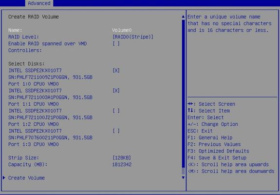
Table 3-8 Items on the Create RAID Volume screen
|
Item |
Description |
Default |
|
Name |
Enter the name of the RAID volume. Make sure the name does not contain special characters. |
N/A |
|
RAID Level |
Select a RAID level. · RAID0(Stripe). · RAID1(Mirror). · RAID5(Parity). · RAID10(RAID0+1). |
RAID0 (Stripe) |
|
Enable RAID spanned over VMD Controllers |
To build a RAID volume over physical drives controlled by different VMD controllers, select this item. |
N/A |
|
Select Disks |
||
|
All available drives, for example: INTEL SSDPE2ME800G4 SN:PHMD63960129800GGN,745.21GB Port 1:3,CPU0,VMD0 |
Select drives over which you want to create the RAID volume. The selected drive is represented by the symbol X. |
No drives are selected for RAID creation. |
|
Stripe Size |
Set the stripe size of the RAID volume. |
N/A |
|
Capacity (MB) |
Displays the total capacity of the RAID volume. |
N/A |
|
Create Volume |
Select Create Volume and press Enter to create the RAID volume. To verify that the volume is correctly created, examine the RAID Volumes section on the Intel VMD controller management submenu screen, as shown in Figure 3-12. |
N/A |
Figure 3-13 shows the configuration submenu screen for a non-RAID physical drive. On the screen, you can view information about the drive and set the drive as a spare or journaling disk, as described in Table 3-9.
Figure 3-13 Non-RAID physical drive configuration submenu screen
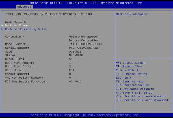
Table 3-9 Items on the non-RAID drive configuration submenu screen
|
Item |
Description |
|
Disk Actions |
|
|
Mark as Spare |
Setting a drive as a spare disk deletes all data on that drive. As a best practice to avoid data loss, back up the data before you perform this action. To specify the drive as a spare disk, select this item, and then select Yes to confirm the action, as shown in Figure 3-14. A spare disk cannot be used to build a RAID volume. |
|
Mark as Journaling Drive |
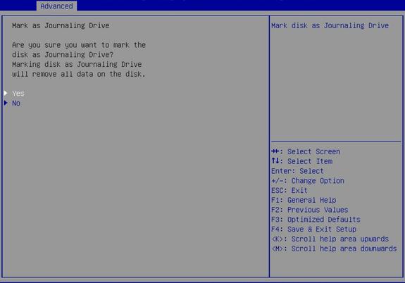
Setting a drive as a journaling drive deletes all data on that drive. As a best practice to avoid data loss, back up the data before you perform this action. To specify the drive as a journaling drive, select this item, and then select Yes to confirm the action, as shown in Figure 3-15. A journaling drive cannot be used to build a RAID volume. |
|
Information about the drive |
|
|
Controller |
Displays the controller information, which is Volume Management Device Controller in this example. |
|
Model Number |
Displays the model number of the drive. |
|
Serial Number |
Displays the serial number of the drive. |
|
Size |
Displays the capacity of the drive. |
|
Status |
Displays whether the drive is a RAID member. |
|
Block Size |
Displays the block size of the drive. |
|
Root Port Number |
Displays the root port number of the drive. |
|
Root Port Offset |
Displays the root port offset of the drive. |
|
Slot Number |
Displays the slot number of the drive. |
|
Socket Number |
Displays the slot number of the processor for the drive. |
|
VMD Controller Number |
Displays controller information. |
|
PCI Bus:Device.Function |
Displays the Bus:Dev:Func of the drive. |
Figure 3-14 Mark as Spare screen
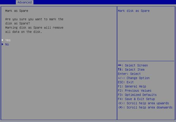
Figure 3-15 Mark as Journaling Drive screen
Driver Health submenu
Figure 3-16 shows the Driver Health submenu screen, on which you can view the health state of a driver or controller. This section uses a controller of a 4-port mLOM Ethernet adapter as an example. For more information about the menu items, see Table 3-10.
Figure 3-16 Driver Health menu screen
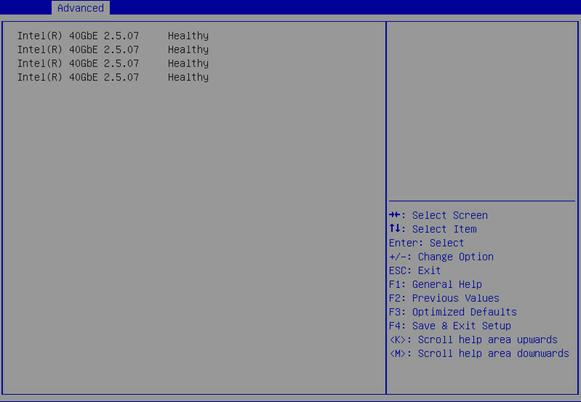
Table 3-10 Items on the Driver Health menu screen
|
Item |
Description |
|
Intel(R) 40GbE 2.5.07 |
Display the health state of a driver or a controller. The scr Options: · Healthy—Normal. · Failed—Abnormal. If the state is Failed, press Enter and follow the instructions to repair the driver or controller. The repair method varies by driver or controller. |
Trusted Computing submenu
The server might contain a trusted platform module (TPM) or a trusted cryptography module (TCM).
If the server does not contain a TPM or TCM module, the Trusted Computing menu screen is as shown in Figure 3-17. The menu items are described in Table 3-11.
If the server contains a TPM module, the Trusted Computing menu screen is as shown in Figure 3-18. The menu items are described in Table 3-12.
If the server contains a TCM module, the Trusted Computing menu screen is as shown in Figure 3-19. The menu items are described in Table 3-13.
Figure 3-17 Trusted Computing menu screen (no security device installed)
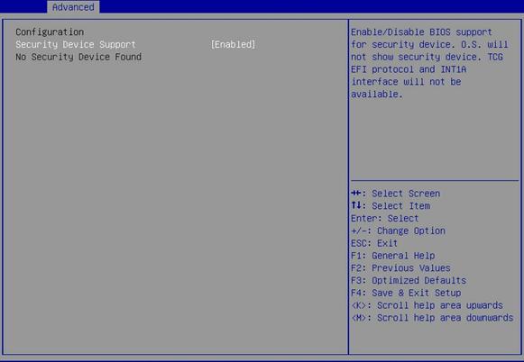
Table 3-11 Items on the Trusted Computing menu screen when no security device is installed
|
Item |
Description |
|
Security Device Support |
Select Enabled or Disabled to enable or disable BIOS support for security devices. |
Figure 3-18 Trusted Computing menu screen (TPM module installed)
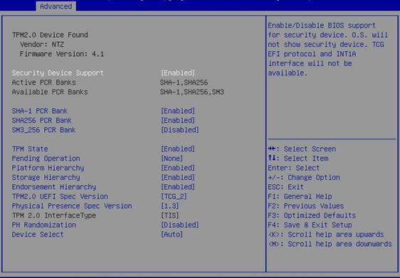
Table 3-12 Items on the Trusted Computing menu screen when a TPM module is installed
|
Item |
Description |
Default |
|
Security Device Support |
Select Enabled or Disabled to enable or disable BIOS support for TPM 2.0. |
N/A |
|
Active PCR Banks |
Displays the active platform configuration register (PCR) banks. |
N/A |
|
Available PCR Banks |
Displays the available PCR banks. |
N/A |
|
SHA-1 PCR Bank |
Select Enabled or Disabled to enable or disable the SHA-1 PCR bank. |
Enabled |
|
SHA256 PCR Bank |
Select Enabled or Disabled to enable or disable the SHA256 PCR bank. |
Enabled |
|
SM3_256PCR Bank |
Select Enabled or Disabled to enable or disable the SM3_256PCR bank. |
Enabled |
|
TPM State |
Select Enabled or Disabled to enable or disable TPM. |
Enabled |
|
Select the TPM operation to be performed during the next boot process. Options are None and TPM Clear. The TPM Clear operation clears the values of measurements in the TPM. |
None |
|
|
Platform Hierarchy |
Select Enabled or Disabled to enable or disable platform hierarchy. |
Enabled |
|
Storage Hierarchy |
Select Enabled or Disabled to enable or disable storage hierarchy. |
Enabled |
|
Endorsement Hierarchy |
Select Enabled or Disabled to enable or disable endorsement hierarchy. |
Enabled |
|
TPM 2.0 UEFI Spec Version |
Select the supported Trusted Computing Group (TCG) specification version. Options: · TCG_1_2—Compatible with Windows 8 and Windows 10. · TCG_2—Specifies the TCG 2 protocol and event format for Windows 10 and higher versions. |
TCG_2 |
|
Physical Presence Spec Version |
Select the Physical Presence Interface (PPI) specification version to be reported to the OS. Options: · 1.2. · 1.3. This option might be not supported by some HCK tests. |
1.3 |
|
TPM 2.0 InterfaceType |
Displays the TPM 2.0 interface type. |
N/A |
|
PH Randomization |
Select Enabled or Disabled to enable or disable platform hierarchy randomization. |
Disabled |
|
Select the supported TPM version. · TPM1.0—Select this option only if a TPM 1.0 module is installed. · TPM2.0—Select this option only if a TPM 2.0 module is installed. · Auto—Select this option to have the system automatically select TPM 1.0 or TPM 2.0. The default is TPM 2.0. If TPM 2.0 is not present, TPM 1.0 is selected. |
Auto |
Figure 3-19 Trusted Computing menu screen (TCM module installed)
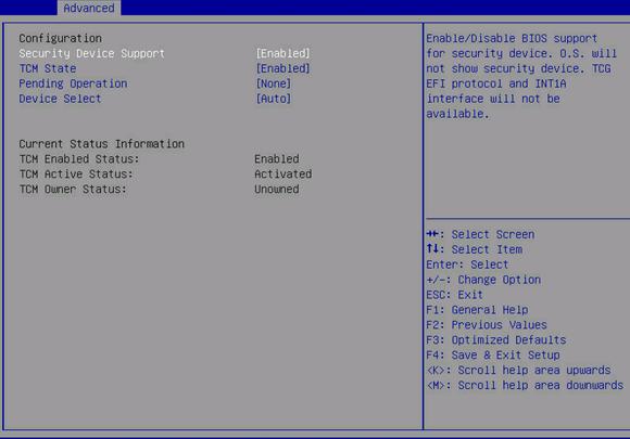
Table 3-13 Items on the Trusted Computing menu screen when a TCM module is installed
|
Description |
Default |
|
|
Configuration |
||
|
Security Device Support |
Select Enabled or Disabled to enable or disable BIOS support for security devices. |
Enabled |
|
TCM State |
Select Enabled or Disabled to enable or disable TCM. |
Enabled |
|
Pending Operation |
Select the TCM operation to be performed during the next boot process. Options are None and TCM Clear. The TCM Clear operation clears the values of measurements in the TCM. |
None |
|
Device Select |
Select the supported TPM version. · TPM1.0—Select this option only if a TPM 1.0 module is installed. · TPM2.0—Select this option only if a TPM 2.0 module is installed. · Auto—Select this option to have the system automatically select TPM 1.0 or TPM 2.0. The default is TPM 2.0. If TPM 2.0 is not present, TPM 1.0 is selected. |
Auto |
|
Current Status Information |
||
|
TCM Enabled Status |
Indicates whether TCM is enabled or disabled. |
N/A |
|
TCM Active Status |
Indicates whether TCM is activated or deactivated. |
N/A |
|
TCM Owner Status |
Indicates the TCM ownership status. Options are Owned and Unowned. |
N/A |
ACPI Settings submenu
The ACPI Settings menu contains the ACPI options for you to configure OS-directed configuration and power management of the server. The menu items are described in Table 3-14.
Figure 3-20 ACPI Settings menu screen
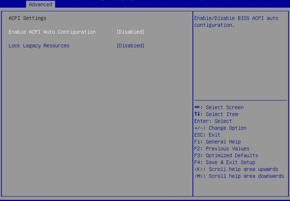
Table 3-14 Items on the ACPI Settings menu screen
|
Item |
Description |
Default |
|
Enable ACPI Auto Configuration |
Select Enabled or Disabled to enable or disable ACPI auto configuration. ACPI auto configuration allows the operating system to control and allocate power on the server hardware. |
Disabled |
|
Lock Legacy Resources |
Select Enabled or Disabled to enable or disable lock of legacy resources. |
Disabled |
Serial Port Console Redirection submenu
Figure 3-21 shows the Serial Port Console Redirection menu screen, on which you can configure console redirection settings as described in Table 3-15.
Figure 3-21 Serial Port Console Redirection menu screen
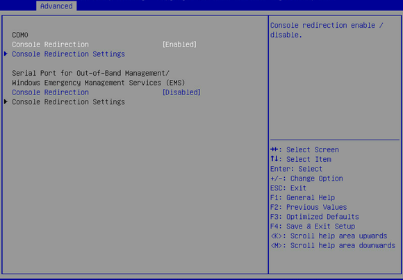
Table 3-15 Items on the Serial Port Console Redirection menu screen
|
Item |
Description |
Default |
|
COM0 |
Serial port COM0. |
N/A |
|
Console Redirection |
Select Enabled or Disabled to enable or disable console redirection on the serial port (COM0). |
Enabled |
|
Open the Console Redirection Settings submenu for COM0, as shown in Figure 3-22. The Console Redirection Settings submenu is accessible only when Console Redirection is enabled on COM0. |
N/A |
|
|
Serial Port for Out-of-Band Management/Windows Emergency Management Services (EMS) |
Serial port for out-of-band management or Windows Emergency Management Services (EMS). |
N/A |
|
Console Redirection |
Select Enabled or Disabled to enable or disable console redirection on the serial port. |
Disabled |
|
Console Redirection Settings |
Open the Console Redirection Settings submenu for the out-of-band management port, as shown in Figure 3-23. The Console Redirection Settings submenu is accessible only when Console Redirection is enabled for the out-of-band management port. |
N/A |
Figure 3-22 shows the Console Redirection Settings menu screen for COM0. The menu items are described in Table 3-16.
Figure 3-22 Console Redirection Settings menu screen (COM0)
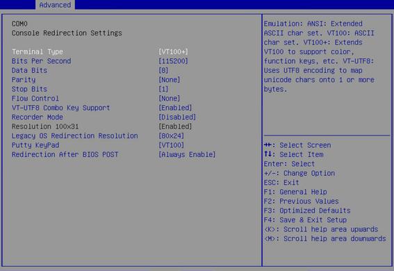
Table 3-16 Items on the Console Redirection Settings menu screen (COM0)
|
Item |
Description |
Default |
|
Terminal Type |
Select the type of terminal used for console redirection. Options: · VT100—Uses a supported VT100 video terminal with the ASCII character set. · VT100+—Uses a supported VT100-plus video terminal and its character set. VT100+ supports colors and function keys. · VT-UTF8—Uses a video terminal with the UTF-8 character set. · ANSI—Uses the ANSI character set, which is an extended ASCII character set. |
VT100+ |
|
Bits Per Second |
Set the baud rate of the serial port in bits per second. Options: · 9600. · 19200. · 38400. · 57600. · 115200. This baud rate setting must match the setting on the remote terminal. As a best practice, set a low speed on a long or noisy serial line. |
115200 |
|
Data Bits |
Set the number of bits used to represent one character of data. Options: · 7. · 8. |
8 |
|
Parity |
Set the parity bit to be sent with the data bits for transmission error detection. Options: · None—No parity bit is sent. · Even—Sets the parity bit so that the number of ones in the data set is an even number. · Odd—Sets the parity bit so that the number of ones in the data set is an odd number. · Mark—Always sets the parity bit to 1. This setting cannot be used for error detection. · Space—Always sets the parity bit to 0. This setting cannot be used for error detection. |
None |
|
Stop Bits |
Set the number of stop bits used to indicate the end of a serial data packet. Options: · 1. · 2. Two stop bits might be required for communications with a slow device. |
1 |
|
Flow Control |
Select a flow control method to prevent data loss from buffer overflow. Options: · None—No flow control is used. · Hardware RTS/CTS—Flow control that uses the ready to send/clear to send (RTS/CTS) signal. When you select this option, make sure it is supported on the serial port. If you enable hardware RTS/CTS on a serial port that does not support hardware flow control (such as a port that uses a USB-to-serial cable), or on a serial port with no cable connected, the following issues might occur: · Failure to load the option ROM of embedded and external PCIe devices. · Screen blackout. · Cursor flickering. |
None |
|
VT-UTF8 Combo Key Support |
Select Enabled or Disabled to enable or disable VT-UTF8 combination key support for ANSI/VT100 terminals. |
Enabled |
|
Recorder Mode |
Select Enabled or Disabled to enable or disable the recorder mode, which is used to capture terminal text data. |
Disabled |
|
Resolution 100×31 |
Select Enabled or Disabled to enable or disable enhanced terminal resolution (100 × 31). |
N/A |
|
Legacy OS Redirection Resolution |
Set the resolution for legacy OS redirection. Options: · 80×24. · 80×25. |
80×24 |
|
Putty KeyPad |
Select a mode to change the action of the function keys and keypad in PuTTY. Options: · VT100. · LINUX. · XTERMR6. · SCO. · ESCN. · VT400. |
VT100 |
|
Configure the legacy console redirection setting after BIOS POST. Options: · Always Enable—Legacy console redirection is always enabled for legacy OS. · BootLoader—Legacy console redirection is disabled before booting to legacy OS. |
Always Enable |
Figure 3-23 shows the Console Redirection Settings menu for the out-of-band management port. The menu items are described in Table 3-17.
Figure 3-23 Console Redirection Settings menu screen (out-of-band management serial port)
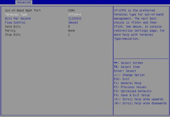
Table 3-17 Items on the Console Redirection Settings menu screen (out-of-band management port)
|
Item |
Description |
Default |
|
Out-of-Band Mgmt Port |
Indicates the out-of-band management serial port. This port allows Microsoft Windows EMS to remotely access the Window OS to collect fault information. |
N/A |
|
Terminal Type |
Select the type of terminal used for console redirection. Options: · VT100—Uses a supported VT100 video terminal with the ASCII character set. · VT100+—Uses a supported VT100-plus video terminal and its character set. VT100+ supports colors and function keys. · VT-UTF8—Uses a video terminal with the UTF-8 character set. · ANSI—Uses the ANSI character set, which is an extended ASCII character set. |
VT100+ |
|
Bits Per Second |
Set the data transfer rate of the serial port in bits per second. Options: · 9600. · 19200. · 57600. · 115200. This data transfer rate setting must match the setting on the remote terminal. As a best practice, set a low speed on a long or noisy serial line. |
115200 |
|
Flow Control |
Select a flow control method to prevent data loss from buffer overflow. Options: · None—No flow control is used. · Hardware RTS/CTS—Flow control that uses the ready to send/clear to send (RTS/CTS) signal. When you select this option, make sure it is supported on the serial port. · Software Xon/Xoff—Flow control that uses the XON (transmit ON) and XOFF (transmit OFF) control characters. When the data transfer rate exceeds 1200 bits per second, the receiver sends an XOFF to have the sender stop transmission. The sender will resume the transmission only when it receives an XON from the receiver. |
None |
|
Displays the number of bits used to represent one character of data. |
N/A |
|
|
Parity |
Displays the parity bit sent with the data bits for transmission error detection. |
N/A |
|
Stop Bits |
Displays the number of stop bits used to indicate the end of a character frame. |
N/A |
Slot x:Port x
Ethernet interfaces, storage controllers, and NVMe drives that have an Option ROM are displayed on the Advanced screen as Slot x:Port x entries. For Ethernet interfaces, Slot x represent the slot number of the Ethernet adapter that contains the interface and Port x represents the port index of the interface on the Ethernet adapter.
The Slot x:Port x submenu screen is generated by the option ROM of a PCIe module and the items on the screen vary by vendor. This section uses the Slot 9-mLOM:Port 1 entry for the embedded mLOM Ethernet adapter as an example. Figure 3-24 shows the Ethernet interface configuration submenu screen of the Slot 9-mLOM:Port 1 entry. The menu items are described in Table 3-18.
Figure 3-24 Slot x:Port x entry submenu screen
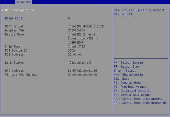
Table 3-18 Items on the Ethernet interface configuration menu screen
|
Item |
Description |
Default |
|
NIC Configuration |
Open the NIC configuration submenu menu, as shown in Figure 3-25. |
N/A |
|
Blink LEDs |
Set the number of seconds for which the port connection status LED keeps blinking. Value range: 0 to 15. |
0 |
|
UEFI Driver |
Displays the UEFI driver name. |
N/A |
|
Adapter PBA |
Displays the network adapter PBA number. |
N/A |
|
Device Name |
Displays the name of the embedded NIC. |
N/A |
|
Chip Type |
Displays the chip type of the NIC. |
N/A |
|
PCI Device ID |
Displays the ID of the PCI device. |
N/A |
|
PCI Address |
Displays the address of the PCI device. |
N/A |
|
Link Status |
Displays the link status. Options: · Disconnected. · Connected. |
N/A |
|
MAC Address |
Displays the MAC address of the embedded NIC. |
N/A |
|
Virtual MAC Address |
Displays the virtual MAC address of the embedded NIC. |
N/A |
Figure 3-25 shows the NIC configuration screen, on which you can configure the link speed and enable or disable Wake On LAN for the Ethernet interface as described in Table 3-19.
Figure 3-25 NIC Configuration screen
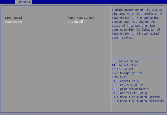
Table 3-19 Items on the NIC Configuration screen
|
Item |
Description |
Default |
|
Link Speed |
Display the link speed setting. The setting is fixed at Auto Negotiated, which is not user configurable. |
N/A |
|
Wake On LAN |
Select Enabled or Disabled to enable or disable waking up the system from a low power mode remotely. If this option is enabled, the server is wakened up when it receives an out-of-band magic packet. |
Disabled |
PCI Subsystem Settings submenu
Figure 3-26 shows the PCI Subsystem Settings menu screen, on which you can configure PCI subsystem settings as described Table 3-20.
Figure 3-26 PCI Subsystem Settings menu screen
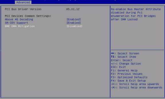
Table 3-20 Items on the PCI Subsystem Settings menu screen
|
Item |
Description |
Default |
|
PCI Bus Driver Version |
Displays the PCI bus driver version. |
N/A |
|
PCI Devices Common Settings |
||
|
Above 4G Decoding |
Select Enabled or Disabled to enable or disable decoding of 64-bit PCI devices in a 4 GB or greater address space. As a best practice, enable this option if the PCIe device has a 4 GB or higher-capacity VRAM. For example, disabling this option can cause an M60 or K80 GPU to get stuck in the EarlyPOST 100% phase, preventing you from accessing the BIOS setup menu or the OS. |
Enabled |
|
SR-IOV Support |
Select Enabled or Disabled to enable or disable the support for PCIe single-root I/O virtualization (SR-IOV). By default, the OS allocates I/O resources if the PCIe card supports SR-IOV. If the PCIe card does not support SR-IOV, SR-IOV is automatically disabled. |
Enabled |
|
BME DMA Mitigation |
Select Enabled or Disabled to enable or disable DMA attack prevention. With this feature enabled, the performance of PCIe devices will degrade. |
Disabled |
Network Stack Configuration submenu
The network stack configuration is used only in UEFI mode for the server to set up a pre-boot network connection for OS deployment through Preboot eXecution Environment (PEX) over the network.
Figure 3-27 shows the Network Stack Configuration menu screen, on which you can configure UEFI network stack settings as described in Table 3-21.
Figure 3-27 Network Stack Configuration menu screen
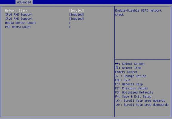
Table 3-21 Items on the Network Stack Configuration menu screen
|
Item |
Description |
Default |
|
Network Stack |
Select Enabled or Disabled to enable or disable the UEFI network stack. |
Enabled |
|
Select Enabled or Disabled to enable or disable loading the OS over an IPv4 network. If Disabled is selected, the IPv4 PEX boot option will not be created. |
Enabled |
|
|
IPv6 PXE Support |
Select Enabled or Disabled to enable or disable loading the OS over an IPv6 network. If Disabled is selected, the IPv6 PEX boot option will not be created. |
Enabled |
|
Media detect count |
Set the maximum number of media presence detections. Value range: 1 to 50. |
1 |
|
PXE Retry Count |
Set the maximum number of PXE retries. Value range: 0 to 50. A value of 0 indicates that the number of PEX retries is not limited. |
1 |
CSM Configuration submenu
The configuration support module (CSM) provides UEFI compatibility with OSs that do not support UEFI boot mode.
Figure 3-28 shows the CSM Configuration menu screen, on which you can configure CMS settings as described in Table 3-22.
Figure 3-28 CSM Configuration menu screen
Table 3-22 Items on the CSM Configuration menu screen
|
Item |
Description |
Default |
|
CSM Support |
Select Enabled or Disabled to enable or disable support for UEFI-incapable operating systems. In legacy boot mode, the setting is always Enabled and cannot be changed. |
Enabled |
|
Option ROM Execution |
||
|
Option ROM Policy |
This item is available only when CSM Support is set to Enabled. Options: · Auto—Automatically load the option ROMs. · Custom—Customize the option ROM load methods for NICs, storage devices, video devices, and other PCI devices. The configuration submenus (Network, Storage, Video, and Other PCI Devices) are available only when the Custom option is selected. |
Auto |
|
Network |
Select the option ROM load method for NICs. Options: · UEFI—Load the option ROM for NICs in UEFI boot mode. · Legacy—Load the option ROM for NICs in legacy boot mode. |
In UEFI boot mode: UEFI. In legacy boot mode: Legacy. |
|
Storage |
Select the option ROM load method for storage devices. Options: · UEFI—Load the option ROM for storage devices in UEFI boot mode. · Legacy—Load the option ROM for storage devices in legacy boot mode. |
In UEFI boot mode: UEFI. In legacy boot mode: Legacy. |
|
Select the option ROM load method for video devices. Options: · UEFI—Load the option ROM for video cards in UEFI boot mode. · Legacy—Load the option ROM for video cards in legacy boot mode. |
In UEFI boot mode: UEFI. In legacy boot mode: Legacy. |
|
|
Other PCI devices |
Select the option ROM load method for other PCI devices such as input devices. Options: · UEFI—Load the option ROM for other PCI devices in UEFI boot mode. · Legacy—Load the option ROM for other PCI devices in legacy boot mode. |
In UEFI boot mode: UEFI. In legacy boot mode: Legacy. |
NVMe Configuration submenu
Figure 3-29 shows the NVMe Configuration menu screen, on which all installed NVMe devices are displayed. You can select an NVMe device to view its information as shown in Figure 3-30.
|
|
NOTE: You cannot turn on state LEDs of NVMe drives by using VMD in the BIOS. |
Figure 3-29 NVMe Configuration menu screen
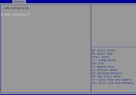
Figure 3-30 NVMe device information screen

Table 3-23 Items on the NVMe device information screen
|
Item |
Description |
|
Slot: Port: |
Displays the slot number and port number of the NVMe device. |
|
Bus:Dev:Func |
Displays the Bus:Dev:Func of the NVMe device. |
|
Model Number |
Displays the model number of the NVMe device. |
|
Total Size |
Displays the total size of the NVMe device. |
|
Vendor ID |
Displays the vendor ID of the NVMe device. |
|
Device ID |
Displays the device ID of the NVMe device. |
|
Namespace |
Displays the namespace of the NVMe device. |
USB Configuration submenu
Figure 3-31 shows the USB Configuration menu screen, on which you can view connected USB devices and configure USB settings as described in Table 3-24.
Figure 3-31 USB Configuration menu screen
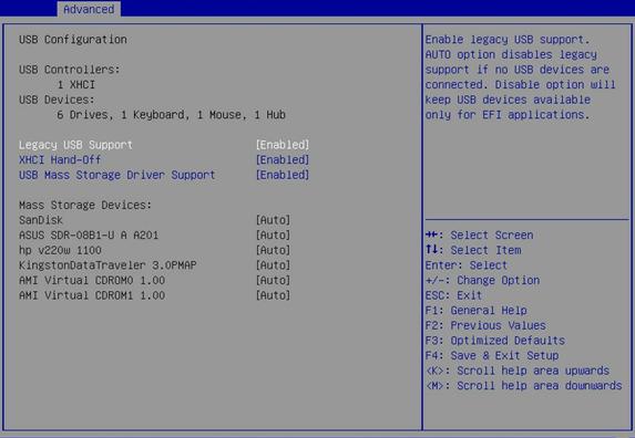
Table 3-24 Items on the USB Configuration menu screen
|
Item |
Description |
Default |
|
USB Controllers |
Displays the detected USB controllers. The system supports eXtensible Host Controller (XHCI) controllers that support USB 3.0. |
N/A |
|
USB Devices |
Displays the numbers of connected USB devices, including drives, keyboards, mice, and hubs. The server has one embedded USB hub in addition to the connected USB hubs. |
N/A |
|
Legacy USB Support |
Select whether to enable the support for legacy USB devices. Options: · Enabled—Legacy USB support is always enabled. · Disabled—USB devices are available only for EFI applications. · Auto—The system automatically disables legacy USB support if no USB devices are connected. |
Enabled |
|
XHCI Hand-off |
The xHCI setting that specifies the owner of the control over USB 3.0 ports. Options: · Enabled—Hands off the control over USB 3.0 ports to the OS after the OS loads. · Disabled—BIOS controls USB 3.0 ports. |
Enabled |
|
USB Mass Storage Driver Support |
Select Enabled or Disabled to enable or disable the support for USB mass storage drivers. |
Enabled |
|
This section displays the installed mass storage devices. |
N/A |
|
|
Dual SD Card RAID LUN |
This option is available only if a dual SD card expander module is installed with a minimum of one SD card. When you manage SD cards, follow these guidelines: · The dual SD card expander module is not hot swappable. However, the SD cards are hot swappable. · For redundancy and storage use efficiency, install two same-capacity SD cards. · If an SD card fails while the server is operating, replace that SD card on line, and then power cycle the server. This replacement procedure ensures that the server can restore the data on the new SD card. Data loss might occur if you replace the failed SD card after powering off the server. |
N/A |
|
SanDisk |
Indicates that a SanDisk USB flash drive is present. |
N/A |
|
ASUS SDR-08B1-U A A301 |
Indicates that an ASUS SDR-08B1-U A A301 USB drive is present. |
N/A |
|
Hp v220w 1100 |
Indicates that an HP v220w 1100 USB drive is present. |
N/A |
|
KingstonDataTraveler 3.0PMAP |
Indicates that a KingstonDataTraveler 3.0PMAP USB drive is present. |
N/A |
|
AMI Virtual CDROM0 1.00 |
Indicates that an AMI Virtual CDROM0 1.00 drive is present. |
N/A |
|
H3C Virtual CDROM0 1.00 |
Indicates that an H3C Virtual CDROM0 1.00 drive is present. A virtual CD-ROM drive provides the same functionality as a physical CD-ROM drive. By default, virtual CDROM0 is mounted when you open the remote console. |
N/A |
|
H3C Virtual Floppy0 1.00 |
Indicates that an H3C Virtual Floppy0 1.00 drive is detected. A virtual floppy drive provides the same functionality as a physical floppy drive. By default, virtual Floppy0 is mounted when you open the remote console. |
N/A |
|
H3C Virtual HDisk0 1.00 |
Indicates that an H3C Virtual HDisk0 1.00 drive is present. A virtual hard disk drive provides the same functionality as a physical hard disk drive. By default, Virtual HDisk0 is mounted when you open the remote console. |
N/A |
|
H3C Virtual CDROM1 1.00 |
Indicates that an H3C Virtual CDROM1 1.00 USB driver is present. A virtual CD-ROM drive provides the same functionality as a physical CD-ROM drive. By default, Virtual CDROM1 is mounted when you open the remote console. |
N/A |
|
H3C Virtual Floppy1 1.00 |
Indicates that an H3C Virtual Floppy1 1.00 drive is present. A virtual floppy drive provides the same functionality as a physical floppy drive. By default, Virtual Floppy1 is mounted when you open the remote console. |
N/A |
|
H3C Virtual HDisk1 1.00 |
Indicates that an H3C Virtual HDisk1 1.00 drive is present. A virtual hard disk drive provides the same functionality as a physical hard disk drive. By default, Virtual HDisk1 is mounted when you open the remote console. |
N/A |
Platform Configuration menu
As shown in Figure 3-32, the Platform Configuration menu contains the submenus described in Table 3-25.
Figure 3-32 Platform Configuration menu screen
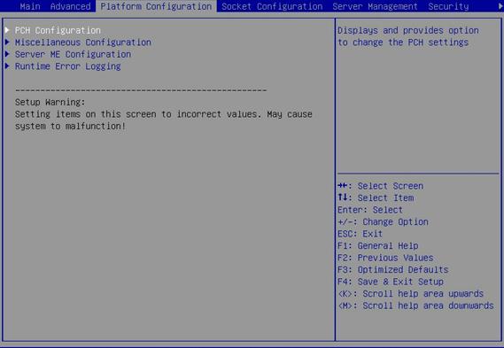
Table 3-25 Items on the Platform Configuration menu screen
|
Item |
Description |
|
PCH Configuration |
Submenu for configuring the platform controller hub (PCH). |
|
Miscellaneous Configuration |
Submenu for configuring miscellaneous settings, including video display device and debug mode settings. |
|
Server ME Configuration |
Submenu for configuring the server management engine (ME). |
|
Runtime Error Logging |
Submenu for configuring runtime error logging. |
PCH Configuration submenu
Figure 3-33 shows the PCH Configuration submenu screen, on which you can configure PCH settings as described in Table 3-26.
Figure 3-33 PCH Configuration submenu screen
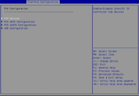
Table 3-26 Items on the PCH Configuration submenu screen
|
Item |
Description |
|
PCH Devices |
Submenu for configuring PCH devices, as shown in Figure 3-34. The submenu menu items are described in Table 3-27. |
|
PCH SATA Configuration |
Submenu for configuring PCH SATA settings, as shown in Figure 3-35. The submenu menu items are described in Table 3-28. |
|
PCH sSATA Configuration |
Submenu for configuring PCH sSATA settings, as shown in Figure 3-36. The submenu menu items are described in Table 3-29. |
|
USB Configuration |
Submenu for configuring USB, as shown in Figure 3-37 . The submenu menu items are described in Table 3-30. |
Figure 3-34 PCH Devices submenu screen
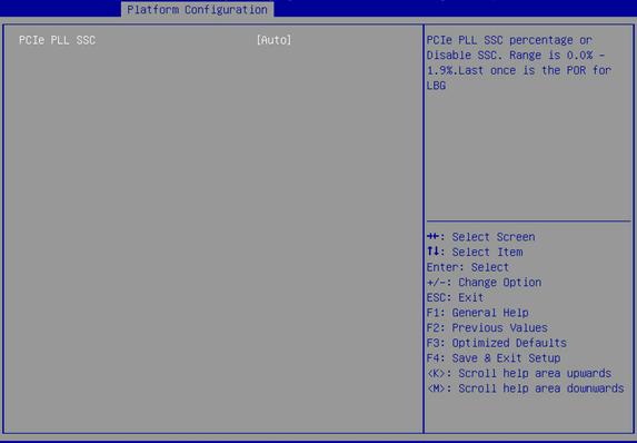
Table 3-27 Items on the PCH Devices submenu screen
|
Item |
Description |
Default |
|
PCIe PLL SSC |
Set the PCIe Phase-Locked Loop (PLL) Spread Spectrum Clocking (SSC) frequency. Options: · Disabled—Disables SSC. · Auto—Allows the BIOS to set the PCIe PLL SSC frequency automatically. · 0.5%—Sets the PCIe PLL SSC frequency to 0.5% of the bus clock frequency. |
Auto |
Figure 3-35 PCH SATA Configuration submenu screen
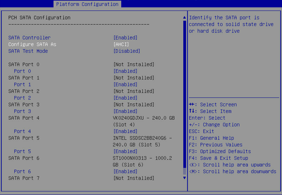
Table 3-28 Items on the PCH SATA Configuration submenu screen
|
Item |
Description |
Default |
|
SATA Controller |
Select Enabled or Disabled to enable or disable the SATA controller. |
Enabled |
|
Configure SATA As |
Select the operating mode of the SATA controller. Options: · AHCI—Uses the AHCI mode, which allows the drives attached to the SATA ports to be used as SATA disks. This mode supports hot swapping of drives. To use this mode, a SATA driver must be installed. · RAID—Uses the RAID mode, which allows creation of a logical drive from multiple independent physical drives. |
AHCI |
|
SATA Test Mode |
Select Enabled or Disabled to enable or disable SATA test mode. |
Disabled |
|
SATA Port N |
Displays the name and slot number of the drive connected to logic PCH SATA port N. If no drive is connected, Not Installed is displayed. For the mapping relations between logic PCH SATA ports and drive backplane ports, see "Mapping relations of PCH SATA/sSATA ports and drive backplane ports." |
N/A |
|
Port N |
Select Enabled or Disabled to enable or disable the drive connected to SATA port N. |
Enabled |
Figure 3-36 PCH sSATA Configuration submenu screen
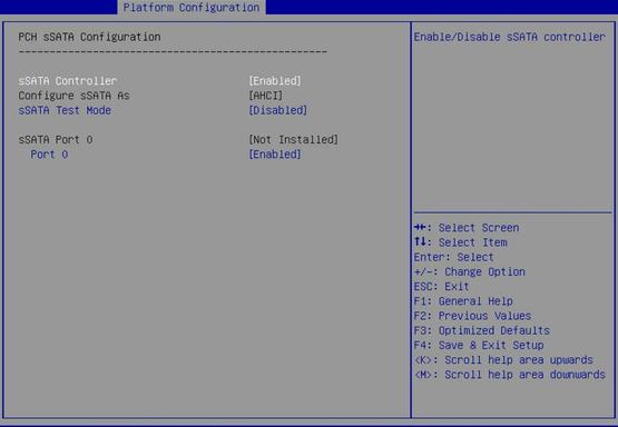
Table 3-29 Items on the PCH sSATA Configuration submenu screen
|
Item |
Description |
Default |
|
sSATA Controller |
Select Enabled or Disabled to enable or disable the sSATA controller. |
Enabled |
|
Configure sSATA As |
Select the operating mode of the sSATA controller. Options: · AHCI—Uses the AHCI mode, which allows the drives attached to the SATA ports to be used as SATA disks. This mode supports hot swapping of drives. To use this mode, a SATA driver must be installed. · RAID—Uses the RAID mode, which allows creation of a logical drive from multiple independent physical drives. |
AHCI |
|
sSATA Test Mode |
Select Enabled or Disabled to enable or disable sSATA test mode. |
Disabled |
|
sSATA Port N |
Displays the name and the slot number of the drive connected to logic PCH sSATA port N. If no drive is connected, Not Installed is displayed. For the mapping relations between logic PCH SATA ports and drive backplane ports, see "Mapping relations of PCH SATA/sSATA ports and drive backplane ports." The number of sSATA ports varies by server model. For example, one sSATA port is available for an H3C UniServer R4900 or R4700 G3 server. Six sSATA ports are available for an H3C UniServer R2900 or R2700 G3 server. |
N/A |
|
Port N |
Select Enabled or Disabled to enable or disable the drive connected to sSATA port N. |
Enabled |
Figure 3-37 USB Configuration submenu screen (H3C UniServer R4900 or R2900 G3 server)
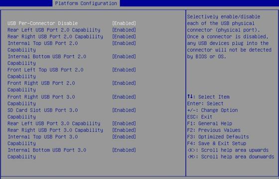
Figure 3-38 USB Configuration submenu screen (H3C UniServer R4700 or R2700 G3 server)
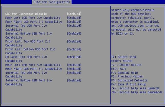
Table 3-30 Items on the USB Configuration submenu screen
|
Parameter |
Description |
Default |
|
USB Per-Connector Disable |
Enable or disable independent control of individual USB connectors on the system board. Options: · Enabled—You can disable the USB connectors on a per-connector basis. · Disabled—You cannot disable the USB connectors on a per-connector basis. If a USB connector is disabled, BIOS or OS does not display the USB device plugged into that connector. NOTE: All subsequent menu items for setting USB port capability are available only if you set USB Per-Connector Disable to Enabled. |
Disabled |
|
Rear Left USB Port 2.0 Capability |
Select Enabled or Disabled to enable or disable the USB 2.0 connector at the left of the rear panel. |
Enabled |
|
Rear Right USB Port 2.0 Capability |
Select Enabled or Disabled to enable or disable the USB 2.0 connector at the right of the rear panel. |
Enabled |
|
Internal Top USB Port 2.0 Capability |
Select Enabled or Disabled to enable or disable the internal top USB 2.0 connector. |
Enabled |
|
Internal Bottom USB Port 2.0 Capability |
Select Enabled or Disabled to enable or disable the internal bottom USB 2.0 connector. |
Enabled |
|
Front Left Top USB Port 2.0 Capability |
Select Enabled or Disabled to enable or disable the top USB port 2.0 connector on the front left chassis ear. |
Enabled |
|
Front Left Bottom USB Port 2.0 Capability |
Select Enabled or Disabled to enable or disable the bottom USB port 2.0 connector on the front left chassis ear. |
Enabled |
|
Front Right USB Port 3.0 Capability |
This item is available only on a 2U server, for example, an H3C UniServer R4900 or 2900 G3 server. Select Enabled or Disabled to enable or disable USB port 3.0 connector on the front right chassis ear. |
Enabled |
|
SD Card Slot USB Port 3.0 Capability |
Select Enabled or Disabled to enable or disable USB 3.0 capability of the SD card slot. |
Enabled |
|
Rear Left USB Port 3.0 Capability |
Select Enabled or Disabled to enable or disable the USB 3.0 connector at the left of the rear panel. |
Enabled |
|
Rear Right USB Port 3.0 Capability |
Select Enabled or Disabled to enable or disable the USB 3.0 connector at the right of the rear panel. |
Enabled |
|
Internal Top USB Port 3.0 Capability |
Select Enabled or Disabled to enable or disable the internal top USB 3.0 connector. |
Enabled |
|
Internal Bottom USB Port 3.0 Capability |
Select Enabled or Disabled to enable or disable the internal bottom USB 3.0 connector. |
Enabled |
Miscellaneous Configuration submenu
Figure 3-39 shows the Miscellaneous Configuration submenu screen, on which you can configure features described in Table 3-31.
Figure 3-39 Miscellaneous Configuration submenu screen
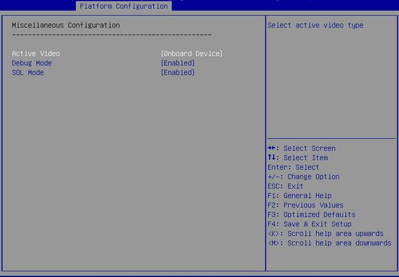
Table 3-31 Items on the Miscellaneous Configuration submenu screen
|
Item |
Description |
Default |
|
Active Video |
Select a monitor to display videos. Options: · Auto—Enables the server to automatically select a monitor to display videos. · Onboard Device—Uses the monitor connected to the onboard VGA connector to display videos. · PCIe Device—Uses the monitor connected to the GPU module in the PCIe slot to display videos. NOTE: In legacy boot mode, the server cannot display the BIOS menus on the monitor connected to the GPU module or VGA connector if the Onboard Device or PCIe Device option is selected, respectively. |
Onboard Device |
|
Debug Mode |
Select Enabled or Disabled to enable or disable outputting the debug log from a BIOS serial port. If debug mode is enabled, you can obtain the debug log by connecting to a BIOS serial port. |
Disabled |
|
SOL Mode |
This item is available only when Debug Mode is set to Enabled. Select Enabled or Disabled to enable or disable SOL mode. With SOL mode enabled, you can obtain the debug log by executing the following command if your operating system is Linux: curl http://HDM_IP/cgi/download_cpsol.cgi | tr -d '\000' > sol.txt The HDM_IP argument represents the IP address of the HDM shared or dedicated network port and the sol.txt argument represents the name of the downloaded file. You can set the log file name as needed. |
Enabled |
Server ME Configuration submenu
Figure 3-40 shows the Server ME Configuration submenu screen, on which you can view the server management engine information described in Table 3-32.
Figure 3-40 Server ME Configuration submenu screen
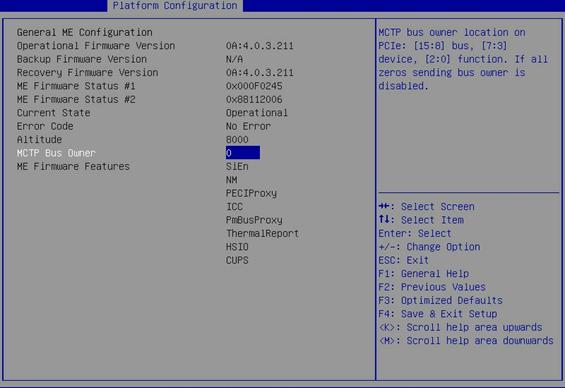
Table 3-32 Items on the Server ME Configuration submenu screen
|
Item |
Description |
|
Operational Firmware Version |
Displays the active firmware version. |
|
Backup Firmware Version |
Displays the backup firmware version. |
|
Recovery Firmware Version |
Displays the recovery firmware version. |
|
ME Firmware Status #1 |
Displays ME firmware status #1. |
|
ME Firmware Status #2 |
Displays ME firmware status #2. |
|
Current State |
Displays the current ME state. |
|
Error Code |
Displays the error code. |
|
Altitude |
Displays the altitude at which the server is located, in meters. The default is 8000 meters (or 26246.72 ft). |
|
MCTP Bus Owner |
Displays the Management Component Transport Protocol (MCTP) bus owner. |
|
ME Firmware Features |
Displays the ME firmware features. |
Runtime Error Logging submenu
Figure 3-41 shows the Runtime Error Logging submenu screen, on which you can configure the runtime error logging as described in Table 3-33.
Figure 3-41 Runtime Error Logging submenu screen
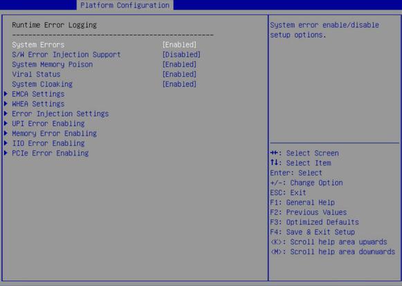
Table 3-33 Items on the Runtime Error Logging submenu screen
|
Item |
Description |
Default |
|
System Errors |
This item controls system error logging, which enables the server to correct system errors automatically and report uncorrectable errors to HDM and the operating system. Select Enabled or Disabled to enable or disable system error logging. |
Enabled |
|
S/W Error Injection Support |
This item is available only when System Errors is set to Enabled. Software error injection tests system performance by injecting software errors. To test system performance, select Enabled. |
Disabled |
|
System Memory Poison |
This item is available only when System Errors is set to Enabled. Select Enabled or Disabled to enable or disable system memory poison. To report event logs to HDM when uncorrectable memory errors are injected, you must set both System Memory Poison and Viral Status to Disabled. |
Enabled |
|
Viral Status |
Select Enabled or Disabled to enable or disable detection of memory-resident viruses. To report event logs to HDM when uncorrectable memory errors are injected, you must set both System Memory Poison and Viral Status to Disabled. |
Enabled |
|
System Cloaking |
System cloaking enables the operating system and software to block corrected errors and uncorrected no action required (UCNA) errors. Select Enabled or Disabled to enable or disable system cloaking. |
Enabled |
|
EMCA Settings |
Access the submenu for configuring the Enhanced Machine Check Architecture (EMCA), as shown in Figure 3-42. The submenu items are described in Table 3-34. |
N/A |
|
WHEA Settings |
Access the submenu for configuring the Windows Hardware Error Architecture (WHEA), as shown in Figure 3-43. The submenu items are described in Table 3-35. |
N/A |
|
Error Injection Settings |
Access the submenu for configuring error injection settings, as shown in Figure 3-44. The submenu items are described in Table 3-36. |
N/A |
|
UPI Error Enabling |
Access the submenu for configuring UltraPath Interconnect (UPI) error reporting, as shown in Figure 3-45. The submenu items are described in Table 3-37. |
N/A |
|
Memory Error Enabling |
Access the submenu for configuring memory error reporting, as shown in Figure 3-46. The submenu items are described in Table 3-38. |
N/A |
|
IIO Error Enabling |
Access the submenu for configuring Integrated I/O module (IIO) error reporting, as shown in Figure 3-47. The submenu items are described in Table 3-39. |
N/A |
|
PCIe Error Enabling |
Access the submenu for configuring PCIe error reporting, as shown in Figure 3-48. The submenu items are described in Table 3-40. |
N/A |
Figure 3-42 EMCA Settings submenu screen
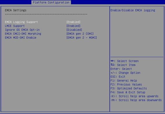
Table 3-34 Items on the EMCA Settings submenu screen
|
Item |
Description |
Default |
|
EMCA Logging Support |
Select Enabled or Disabled to enable or disable EMCA logging. EMCA logging provides MAC error reports for the server. |
Enabled |
|
LMCE Support |
Local machine check exceptions (LMCE) support enables the system to log detected hardware errors in firmware registers. Select Enabled or Disabled to enable or disable LMCE support. |
Enabled |
|
Ignore OS EMCA Opt-in |
This item is available only when System Errors is set to Enabled. Select Enabled or Disabled to enable or disable the ignore OS EMCA opt-in feature. |
Disabled |
|
EMCA CMCI-SMI Morphing |
This item is available only when System Errors is set to Enabled. When EMCA CMCI-SMI morphing is enabled: · The SMI is triggered each time a correctable error occurs. · If the number of correctable errors on the MCBank exceeds the upper limit, the SMI is triggered but the Corrected Machine Check Interrupt (CMCI) is not. Options: · EMCA gen 1 Lite—Enables EMCA CMCI-SMI morphing in EMCA gen 1 lite mode. · EMCA gen 2 CSMI—Enables EMCA CMCI-SMI morphing in EMCA gen 2 CSMI mode. · Disabled—Disables EMCA CMCI-SMI morphing. |
EMCA gen 2 CSMI |
|
EMCA MCE-SMI Enable |
Options: · EMCA gen 1 Dual Mode—Enables EMCA MCE-SMI in EMCA gen1 dual mode. · EMCA gen 2 – MSMI—Enables EMCA MCE-SMI in EMCA gen 2 MSMI mode. · Disabled—Disables EMCA MCE-SMI. |
EMCA gen 2 – MSMI |
Figure 3-43 WHEA Settings submenu screen
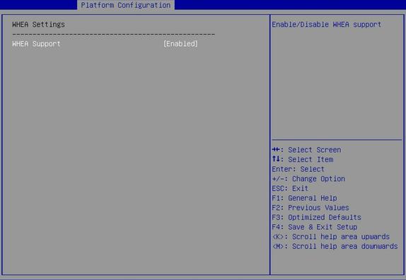
Table 3-35 Items on the WHEA Settings submenu screen
|
Item |
Description |
Default |
|
WHEA Support |
Select Enabled or Disabled to enable or disable WHEA. WHEA provides hardware error reports for the server. |
Enabled |
Figure 3-44 Error Injection Settings submenu screen

Table 3-36 Items on the Error Injection Settings submenu screen
|
Item |
Description |
Default |
|
Mca Bank Error Injection Support |
This item is available only when System Errors is set to Enabled. Select Enabled or Disabled to enable or disable MCA bank error injection. If MCA bank error injection is enabled, the write function of the register into which errors are injected is enabled. |
Disabled |
|
WHEA Error Injection Support |
Select Enabled or Disabled to enable or disable WHEA error injection. |
Disabled |
Figure 3-45 UPI Error Enabling submenu screen
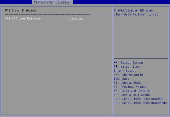
Table 3-37 Items on the UPI Error Enabling submenu screen
|
Item |
Description |
Default |
|
SMI UPI Lane Failover |
Select Enabled or Disabled to enable or disable triggering an SMI upon a UPI lane failover. |
Disabled |
Figure 3-46 Memory Error Enabling submenu screen
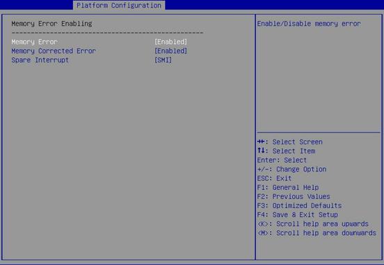
Table 3-38 Items on the Memory Error Enabling submenu screen
|
Item |
Description |
Default |
|
Memory Error |
Select Enabled or Disabled to enable or disable memory error reporting. |
Enabled |
|
Memory Corrected Error |
Select Enabled or Disabled to enable or disable correctable memory error reporting. |
Enabled |
|
Spare Interrupt |
This item is available only when Memory Corrected Error is set to Enabled. Select the type of the spare interrupt to generate upon detection of a memory error. Options: · Disabled—Disables spare interrupt generation. · SMI—Generates an SMI interrupt. |
SMI |
Figure 3-47 IIO Error Enabling submenu screen
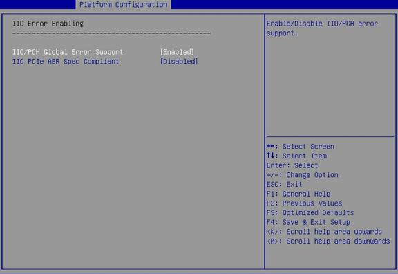
Table 3-39 Items on the IIO Error Enabling submenu screen
|
Item |
Description |
Default |
|
IIO/PCH Global Error Support |
Select Enabled or Disabled to enable or disable IIO/PCH global error reporting. |
Enabled |
|
IIO PCIe AER Spec Compliant |
Select Enabled or Disabled to enable or disable IIO PCIe Advanced Error Reporting (AER) specification compliance checking. |
Disabled |
Figure 3-48 PCIe Error Enabling submenu screen
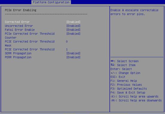
Table 3-40 Items on the PCIe Error Enabling submenu screen
|
Items |
Description |
Default |
|
Corrected Error |
Select Enabled or Disabled to enable or disable PCIe correctable error reporting. |
Enabled |
|
Uncorrected Error |
Select Enabled or Disabled to enable or disable PCIe correctable error reporting. |
Enabled |
|
Fatal Error Enable |
Select Enabled or Disabled to enable or disable PCIe fatal error reporting. |
Enabled |
|
PCIe Corrected Error Threshold Counter |
Select Enabled or Disabled to enable or disable the PCIe correctable error threshold counter. |
Disabled |
|
PCIe Corrected Error Threshold Mask |
This item is available only when PCIe Corrected Error Threshold Counter is set to Enabled. Set the PCIe correctable error threshold mask. |
0 |
|
PCIe Corrected Error Threshold |
This item is available only when PCIe Corrected Error Threshold Counter is set to Enabled. Set the PCIe correctable error threshold. |
1 |
|
SERR Propagation |
Select Enabled or Disabled to enable or disable SERR propagation. |
Enabled |
|
PERR Propagation |
Select Enabled or Disabled to enable or disable PERR propagation. |
Enabled |
Socket Configuration menu
Figure 3-49 shows the Socket Configuration menu screen, on which you can configure CPU, command reference code, UPI, memory, IIO, and advanced power management settings as described in Table 3-41.
Figure 3-49 Socket Configuration menu screen
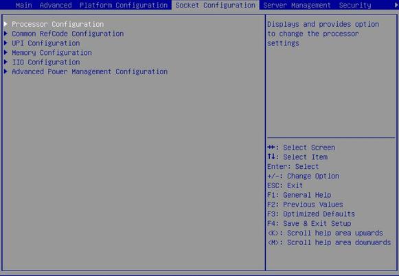
Table 3-41 Items on the Socket Configuration menu screen
|
Item |
Description |
|
Processor Configuration |
Submenu for configuring processors, as shown in Figure 3-50. The submenu items are described in Table 3-44. |
|
Common RefCode Configuration |
Submenu for configuring the common reference code, as shown in Figure 3-53. The submenu items are described in Table 3-45. |
|
UPI Configuration |
Submenu for configuring Intel® UltraPath Interconnect (UPI) parameters, as shown in Figure 3-54. The submenu items are described in Table 3-46. |
|
Memory Configuration |
Submenu for configuring memory parameters, as shown in Figure 3-57. The submenu items are described in Table 3-48. |
|
IIO Configuration |
Submenu for configuring Integrated I/O module (IIO) parameters, as shown in Figure 3-62. The submenu items are described in Table 3-53. |
|
Advanced Power Management Configuration |
Submenu for configuring advanced power management parameters, as shown in Figure 3-71. The submenu items are described in Table 3-60. |
Processor Configuration submenu
Figure 3-50 shows the Processor Configuration submenu screen, on which you can configure features such as hyper-threading and hardware prefetcher for processors.
The submenu items are described in Table 3-42.
Figure 3-50 Processor Configuration submenu screen
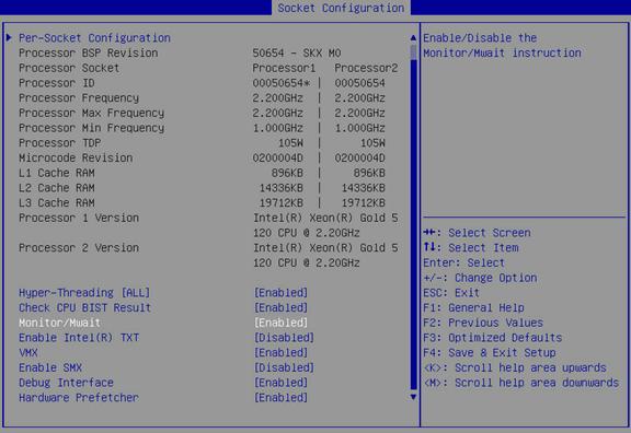
Table 3-42 Items on the Processor Configuration submenu screen
|
Item |
Description |
Default |
|
Per-Socket Configuration |
Access the submenu for per-socket configuration, as shown in Figure 3-51. The submenu items are described in Table 3-43. |
|
|
Processor BSP Revision |
Displays the processor revision. |
N/A |
|
Processor Socket |
Displays the sequence number of the processor socket. |
N/A |
|
Processor ID |
Displays the processor ID. |
N/A |
|
Processor Frequency |
Displays the processor frequency. |
N/A |
|
Processor Max Frequency |
Displays the maximum frequency allowed for each processor. |
N/A |
|
Processor Min Frequency |
Displays the minimum frequency allowed for each processor. |
N/A |
|
Processor TDP |
Displays the thermal design power (TDP) of the processor. |
N/A |
|
Microcode Revision |
Displays the microcode revision. |
N/A |
|
L1 Cache RAM |
Displays the capacity of the level-1 processor cache. |
N/A |
|
L2 Cache RAM |
Displays the capacity of the level-2 processor cache. |
N/A |
|
L3 Cache RAM |
Displays the capacity of the level-3 processor cache. |
N/A |
|
Processor 1 Version |
Displays the version of processor 1. |
N/A |
|
Processor 2 Version |
Displays the version of processor 2. |
N/A |
|
Hyper-Threading [ALL] |
Select Enabled or Disabled to enable or disable hyper-threading for the processors. Hyper-threading improves the overall system performance by enabling each physical processor core to function as two logical processor cores. |
Enabled |
|
Check CPU BIST Result |
Select Enabled or Disabled to enable or disable checking the CPU built-in self-test (BIST) result. If this feature is enabled, the system checks the CPU BIST result and disables process cores that failed the test. If this feature is disabled, the CPU BIST result is ignored. |
Disabled |
|
Monitor/Mwait |
Select Enabled or Disabled to enable or disable MONITOR and MWAIT instructions. For some OSs, to disable CPU C State Control, you must also disable this feature. |
Enabled |
|
Select Enabled or Disabled to enable or disable Intel Trusted Execution Technology (TXT). Intel TXT provides comprehensive data security protection in a virtualized computing environment.
Set Debug Interface to Disabled before enabling Intel TXT. |
Disabled |
|
|
This item is configurable only when Enable Intel(R) TXT is set to Disabled. Select Enabled or Disabled to enable or disable CPU Virtual Machine Extensions (VMX). CPU VMX improves server hardware resource usage by enabling the virtualization layer or OS that supports VMX to use Intel hardware virtualization capabilities. |
Enabled |
|
|
Enable SMX |
This item is configurable only when Enable Intel(R) TXT is set to Disabled. Select Enabled or Disabled to enable or disable Intel Safer Mode Extensions (SMX). |
Disabled |
|
Debug Interface |
Select Enabled or Disabled to enable or disable debug interface. If debug interface is enabled, you can debug the system. |
Enabled |
|
Hardware Prefetcher |
Select Enabled or Disabled to enable or disable hardware prefetcher. If hardware prefetcher is enabled, the CPU prefetches instructions or data from memory to L2 cache before processing the instructions or data. This feature helps improve system performance by reducing memory access time and eliminating potential bottlenecks. |
Enabled |
Figure 3-51 Per-Socket Configuration submenu screen
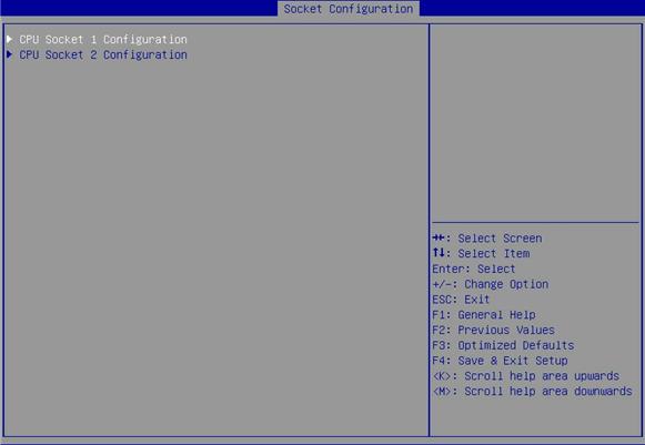
Table 3-43 Items on the Per-Socket Configuration submenu screen
|
Item |
Description |
|
CPU Socket 1 Configuration |
Submenu for configuring processor 1, as shown in Figure 3-52. The submenu items are described in Table 3-44. |
|
CPU Socket 2 Configuration |
Submenu for configuring processor 2. This item is available only when processor 2 is present. You can configure processor 2 in the same way processor 1 is configured. |
Figure 3-52 CPU Socket 1 Configuration submenu screen
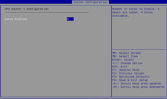
Table 3-44 Items on the CPU Socket 1 Configuration submenu screen
|
Description |
|
|
Cores Enabled |
Set the number of enabled cores for the processor. To enable all cores of the processor, set the value to 0. |
Common RefCode Configuration submenu
Figure 3-53 shows the Common RefCode Configuration submenu screen, on which you can configure memory mapped I/O (MMIO) above 4 GB and non-uniform memory access (NUMA) settings as described in Table 3-45.
Figure 3-53 Common RefCode Configuration submenu screen

Table 3-45 Items on the Common RefCode Configuration submenu screen
|
Item |
Description |
Default |
|
MMIO High Base |
Select the address space for MMIO above 4 GB. Options: · 56T. · 40T. · 24T. · 16T. · 4T. · 1T. · 896G. |
896G |
|
MMIO High Granularity Size |
Select the address allocation size for MMIO above 4 GB. Options: · 1G. · 4G. · 16G. · 64G. · 512G. · 1024G. |
64G |
|
NUMA |
Select Enabled or Disabled to enable or disable NUMA. Non-uniform memory access (NUMA) allows a processor to access its local memory faster than a non-local memory. |
Enabled |
UPI Configuration submenu
Figure 3-53 shows the UPI Configuration submenu screen, from which you can access the UPI General Configuration submenu to configure UPI parameters such as the UPI link frequency.
Figure 3-54 UPI Configuration submenu screen
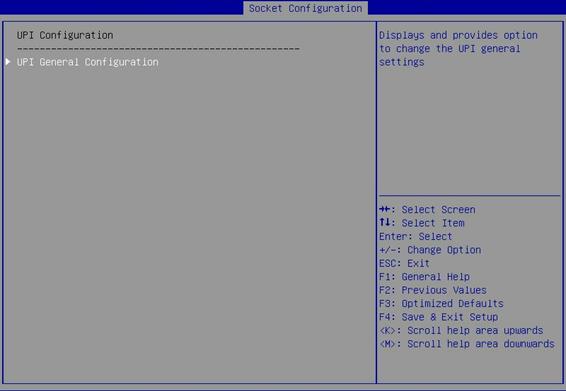
Figure 3-55 shows the UPI General Configuration submenu screen, on which you can configure parameters such as the UPI link frequency and UPI failover support as described in Table 3-46.
Figure 3-55 UPI General Configuration submenu screen
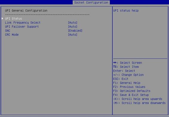
Table 3-46 Items on the UPI General Configuration submenu screen
|
Item |
Description |
Default |
|
Access the submenu that displays UPI information, as shown in Figure 3-56. The submenu items are described in Table 3-47. |
N/A |
|
|
Link Frequency Select |
Select a link frequency. Options: · 9.6 GT/s. · 10.4 GT/s. · Auto. |
Auto |
|
UPI Failover Support |
Select whether to enable UPI failover. Options: · Enabled. · Disabled. · Auto. |
Auto |
|
SNC |
Select whether to enable sub-NUMA clustering (SNC). Options: · Enabled. · Disabled. · Auto. |
Disabled |
|
CRC Mode |
Select a UPI CRC mode. Options: · 16 Bit CRC. · 32 Bit Rolling CRC. · Auto. |
Auto |
Figure 3-56 UPI Status submenu screen
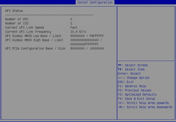
Table 3-47 Items on the UPI Status submenu screen
|
Item |
Description |
|
Number of CPU |
Displays the number of processors. |
|
Number of IIO |
Displays the number of integrated I/O modules. |
|
Current UPI Link Speed |
Displays the current speed of the UPI link. |
|
Current UPI Link Frequency |
Displays the current frequency of the UPI link. |
|
UPI Global MMIO Low Base/Limit |
Displays the UPI global MMIO low base address and limit. |
|
UPI Global MMIO High Base/Limit |
Displays the UPI global MMIO high base address and limit. |
|
UPI PCIe Configuration Base/Size |
Displays the PCIe configuration base address and size. |
Memory Configuration submenu
Figure 3-57 shows the Memory Configuration submenu screen, on which you can configure memory settings such as the memory speed and memory RAS features as described in Table 3-48.
Figure 3-57 Memory Configuration submenu screen
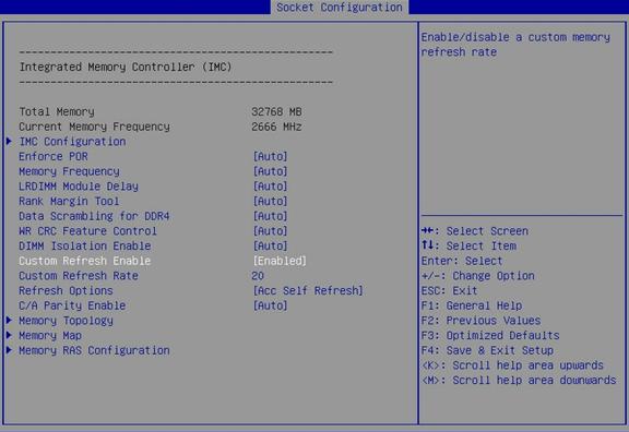
Table 3-48 Items on the Memory Configuration submenu screen
|
Item |
Description |
Default |
|
Total Memory |
Displays the total memory capacity. |
N/A |
|
Current Memory Frequency |
Displays the current memory frequency. |
N/A |
|
IMC Configuration |
Access the submenu for configuring the integrated memory controller (IMC), as shown in Figure 3-58. The submenu items are described in Table 3-49. |
N/A |
|
Enforce POR |
Select whether to enforce POR restrictions on DDR4 frequency selection to improve memory reliability. Options: · Auto. · Enforce POR. · Disabled. |
Auto |
|
Memory Frequency |
Select a memory frequency. Options: · Auto. · 1600. · 1866. · 2133. · 2400. · 2666. |
Auto |
|
LRDIMM Module Delay |
Configure the load-reduced dual inline memory module (LRDIMM) delay setting. Options: · Disabled—Disables the memory regulator controller (MRC) from using SPD bytes 90 to 95 for module delay on LRDIMM memory. · Auto—Enables the system to automatically set the LRDIMM module delay. If the SPD value is 0 or out of range, MRC uses the default setting on the LRDIMM module. |
Auto |
|
Rank Margin Tool |
Select whether to enable the use of the rank margin tool after DDR4 memory training. Options: · Auto—Use the default setting in the MRC. · Disabled—Disables the rank margin tool. · Enabled—Uses the rank margin tool after DDR4 memory training. |
Auto |
|
Data Scrambling for DDR4 |
Select whether to enable data scrambling for enhanced detection of DDR4 address line errors. Options: · Auto. · Disabled. · Enabled. |
Auto |
|
WR CRC Feature Control |
Select whether to enable the write CRC feature. Options: · Auto—Uses the default setting in the MRC. If write CRC is enabled in the MRC, this item displays Auto. · Disabled—Disables write CRC. · Enabled—Enables write CRC. |
Auto |
|
DIMM Isolation Enable |
Select whether to enable DIMM isolation. Options: · Auto—Uses the default setting in the MRC. If DIMM isolation is enabled in the MRC, this item displays Auto. · Disabled—Disables DIMM isolation for command/address verification and the CRC write feature. · Enabled—Enables DIMM isolation for command/address verification and the CRC write feature. |
Auto |
|
Custom Refresh Enable |
Select Enabled or Disabled to enable or disable setting a custom memory refresh rate. |
N/A |
|
Custom Refresh Rate |
This item is available only when Custom Refresh Enable is set to Enabled. Set the memory refresh rate. |
N/A |
|
Refresh Options |
Select a memory refresh mode. Options: · Acc Self Refresh—Enables accelerated memory refresh. · 2x Refresh—Refreshes memory data at twice the normal refresh rate. |
N/A |
|
C/A Parity Enable |
Select whether to enable command and address (C/A) parity check. Options: · Auto—Uses the default setting in the MRC. If C/A parity check is enabled in the MRC, this item displays Auto. · Disabled—Disables parity check on DDR4 commands and addresses. · Enabled—Enables parity check on DDR4 commands and addresses. |
Auto |
|
Memory Topology |
Access the submenu that displays memory information, as shown in Figure 3-59. The submenu items are described in Table 3-50. |
N/A |
|
Memory Map |
Access the submenu for configuring memory mapping and interleaving, as shown in Figure 3-60. You can enable memory interleaving to improve memory read and write performance. The submenu items are described in Table 3-51. |
N/A |
|
Access the submenu for configuring memory reliability, availability, and serviceability (RAS) settings, as shown in Figure 3-61. The submenu items are described in Table 3-52. |
N/A |
Figure 3-58 IMC Configuration submenu screen
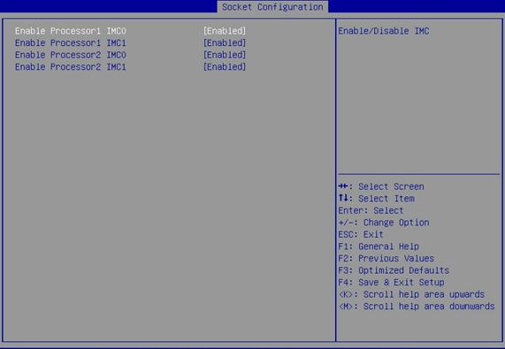
Table 3-49 Items on the IMC Configuration submenu screen
|
Item |
Description |
Default |
|
Enable ProcessorNumber IMC |
Select Enabled or Disabled to enable or disable the integrated memory controller for a processor. |
Enabled |
Figure 3-59 Memory Topology submenu screen
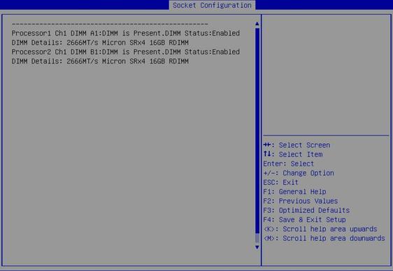
Table 3-50 Items on the Memory Topology submenu screen
|
Item |
Description |
|
Processor1 Ch1 DIMM A1: DIMM is Present.DIMM Status:Enabled.DIMM Details: 2666MT/s Micron SRx4 16GB RDIMM |
Displays information about the memory module of a processor (for example, DIMM A1 in channel 1 of processor 1), including: · Presence of the DIMM. · Enabling status of the DIMM. · Memory specifications: ¡ Memory frequency. ¡ Vendor. ¡ Number of ranks and bit width. ¡ Memory capacity. ¡ Memory type. |
Figure 3-60 Memory Map submenu screen
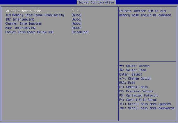
Table 3-51 Items on the Memory Map submenu screen
|
Item |
Description |
Default |
|
Volatile Memory Mode |
Select the volatile memory mode. Options: · 1LM. · 2LM. · Auto. |
1LM |
|
1LM Memory Interleave Granularity |
Select the granularity for 1LM memory interleaving. Options: · 64B Target,64B Channel. · Auto. |
Auto |
|
IMC Interleaving |
Select an interleaving mode for integrated memory controllers. Options: · Auto. · 1-way Interleave. · 2-way Interleave. |
Auto |
|
Channel Interleaving |
Select a memory channel interleaving mode. Options: · Auto. · 1-way Interleave. · 2-way Interleave. · 3-way Interleave. |
Auto |
|
Rank Interleaving |
Select a memory rank interleaving mode. Rank interleaving enables interleaving of memory ranks on the same channel. Options: · Auto. · 1-way Interleave. · 2-way Interleave. · 4-way Interleave. · 8-way Interleave. |
Auto |
|
Socket Interleave Below 4GB |
Select Enabled or Disabled to enable or disable socket interleaving for memory below 4 GB. This item is automatically disabled and cannot be enabled if the NUMA item is enabled. For more information about the NUMA item, see "Common RefCode Configuration submenu." |
Disabled |
Figure 3-61 Memory RAS Configuration submenu screen
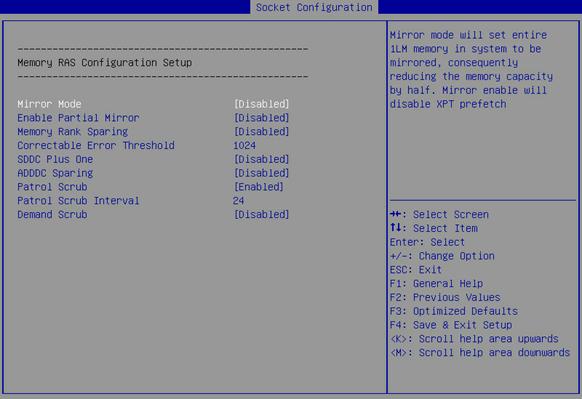
Table 3-52 Items on the Memory RAS Configuration submenu screen
|
Item |
Description |
Default |
|
Mirror Mode |
Select a memory mirroring mode to optimize system reliability by using half the system memory capacity for backup. Options: · Disabled. After you enable memory mirroring, the Total Memory Size item on the Memory Configuration submenu screen displays the total available memory, which is half the installed physical memory. To identify the installed physical memory capacity, access the Smbios Type 17 structure from a shell (for example, the CLI) of the operating system. If all the DIMM slots are installed with DIMMs and memory mirroring is enabled, the memory capacity displayed on the POST self-test screen and the BIOS setup utility is larger than half the total installed physical memory. |
Disabled |
|
Enable Partial Mirror |
Select Mirror Mode 1LM to enable partial mirroring by using 1LM memory or select Disabled to disable partial mirroring. To use partial mirroring, you must select Disabled for Memory Rank Sparing. |
Disabled |
|
Memory Rank Sparing |
Select Enabled or Disabled to enable or disable memory sparing for memory ranks. Memory rank sparing uses some ranks in the memory as spare ranks for the non-spare ranks on the same channel. Memory rank sparing is mutually exclusive with memory mirroring. When the independent RAS mode is set and memory rank sparing is enabled, both the independent RAS mode and memory rank sparing take effect. |
Disabled |
|
Multi Rank Sparing |
Select the number of spare ranks per channel. This item is available only when Memory Rank Sparing is set to Enabled. Options: · One Rank—Uses one spare rank on a channel. To use one spare rank, each channel must have a minimum of two ranks. · Two Rank—Uses two spare ranks on a channel. To use two spare ranks, each channel must have a minimum of four ranks. |
N/A |
|
Set the correctable error threshold. Value range: 0 to 32767. Value 0 indicates that no correctable error threshold is set. |
4096 |
|
|
SDDC Plus One |
Select Enabled or Disabled to enable or disable single device data correction (SDDC) plus one-bit error correction. |
Disabled |
|
ADDDC Sparing |
Select Enabled or Disabled to enable or disable adaptive double device data correction sparing (ADDDC). This feature requires a B/L forced interleaving interval of 64B. ADDDC sparing can correct two-bit memory errors. |
Disabled |
|
Select Enabled or Disabled to enable or disable patrol scrubbing. Patrol scrubbing allows a processor to automatically search for and correct correctable memory errors at regular intervals while the system is idle. |
Enabled |
|
|
Patrol Scrub Interval |
Set the patrol scrub interval. This item is available only when Patrol Scrub is set to Enabled. |
24 |
|
Demand Scrub |
Select Enabled or Disabled to enable or disable demand scrubbing. Demand scrubbing attempts to correct data errors when memory is read. |
Disabled |
IIO Configuration menu
Figure 3-62 shows the IIO Configuration submenu screen, on which you can configure the peripheral component interconnect express (PCIe) slots, including their link speed and maximum payload size, as described in Table 3-53.
Figure 3-62 IIO Configuration submenu screen

Table 3-53 Items on the IIO Configuration submenu screen
|
Item |
Description |
Default |
|
Processor n Configuration |
Access the IIO configuration submenu for a processor, for example, processor 1 or processor 2. The port items on the Processor 1 Configuration submenu vary by server model and PCIe module. Figure 3-63 and Figure 3-64 use the Processor 1 Configuration submenu screen and the Processor 2 Configuration submenu screen for the R4900 G3 server as examples. The submenu items are described in Table 3-54. |
N/A |
|
Intel® VT for Directed I/O (VT-d) |
Access the submenu for enabling or disabling Intel virtualization technology for directed I/O (VT-d), as shown in Figure 3-67. The submenu items are described in Table 3-56. |
N/A |
|
Intel® VMD technology |
Access the submenu for configuring Intel Volume Management Device (VMD) technology, as shown in Figure 3-68 . The submenu items are described in Table 3-57. |
N/A |
|
PCIe Hot Plug |
Select Enabled or Disabled to enable or disable hot swapping of PCIe modules. |
Enabled |
Figure 3-63 Processor 1 Configuration submenu screen
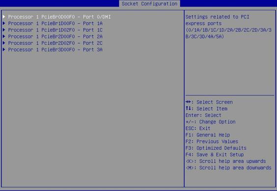
Figure 3-64 Processor 2 Configuration submenu screen
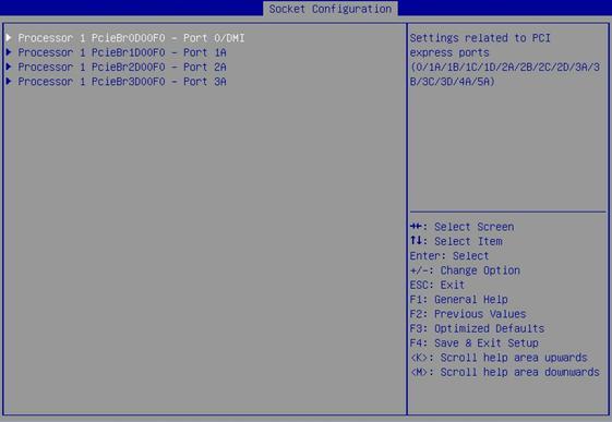
Table 3-54 Items on the Processor n Configuration submenu screen
|
Item |
Description |
|
PCIe port submenu items, for example: Processor 1 PcieBr0D00F0 - Port 0/DMI Processor 1 PcieBr1D00F0 - Port 1A Processor 2 PcieBr1D02F0 - Port 1C |
Submenus for configuring PCIe ports. Figure 3-65 shows the submenu for configuring Processor 1 PcieBr0D00F0 - Port 0/DMI, which slightly differs from the submenu for other PCIe ports, as shown in Figure 3-66 . The submenu items are described in Table 3-55. NOTE: In this document, the PCIe port identified with "DMI" is referred to as the DMI PCIe port. The PCIe ports that do not have the "DMI" identification are referred to as non-DMI PCIe ports. |
Figure 3-65 Submenu screen for Processor 1 PcieBr0D00F0 - Port 0/DMI
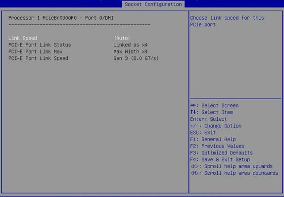
Figure 3-66 Submenu screen for non-DMI PCIe ports
Table 3-55 Items on the Processor 1 PcieBr0D00F0 - Port 0/DMI submenu screen
|
Item |
Description |
Default |
|
PCI-E Port |
This item is available only for non-DMI PCIe ports. Select whether to enable the PCIe port. Options: · Auto. · Enabled. · Disabled. If Disabled is selected, the Hot Plug Capable and Link Speed items will not be available. |
Auto |
|
Hot Plug Capable |
This item is available only for non-DMI PCIe ports. Select Enabled or Disabled to enable or disable the hot swapping feature on the PCIe port. |
N/A |
|
Surprise Hot Plug Capable |
This item is available only for non-DMI PCIe ports. Select Enabled or Disabled to enable or disable the surprise hot swapping feature on the PCIe port. |
N/A |
|
Link Speed |
Select a link speed for the PCIe port. Options: · Auto. · Gen 1 (2.5 GT/s). · Gen 2 (5.0 GT/s). · Gen 3 (8.0 GT/s). |
Auto |
|
PCI-E Port Link Status |
Displays the PCIe port link status. |
N/A |
|
PCI-E Port Link Max |
Displays the maximum bandwidth of the PCIe port link. |
N/A |
|
PCI-E Port Link Speed |
Displays the PCIe port link speed. |
N/A |
Figure 3-67 Intel® VT for Directed I/O (VT-d) submenu screen
Table 3-56 Items on the Intel® VT for Directed I/O (VT-d) submenu screen
|
Item |
Description |
Default |
|
Select Enabled or Disabled to enable or disable Intel virtualization technology for directed I/O (VT-d). Intel VT-d enhances system security and reliability, and improves the performance of I/O devices in a virtualized environment. |
Enabled |
Figure 3-68 Intel® VMD technology submenu screen
Table 3-57 Items on the Intel® VMD technology submenu screen
|
Item |
Description |
|
Intel® VMD for Volume Management Device on Processor 1 |
VMD configuration submenu for the volume management device on Processor 1, as shown in Figure 3-69. The submenu items are described in Table 3-58. |
|
Intel® VMD for Volume Management Device on Processor 2 |
VMD configuration submenu for the volume management device on Processor 2, as shown in Figure 3-70. The submenu items are described in Table 3-59. |
Figure 3-69 Intel® VMD for Volume Management Device on Processor 1 submenu screen
Table 3-58 Items on the Intel® VMD for Volume Management Device on Processor 1submenu screen
|
Item |
Description |
Default |
|
Intel® VMD for Volume Management Device for PStack0 |
This item is available only in UEFI boot mode. Select whether to enable Intel® VMD for the volume management device in PStack0. Options: · Disabled—Disables Intel® VMD for the volume management device for PStack0. · Enabled—Enables Intel® VMD for the volume management device for PStack0. · Auto—Enables Intel® VMD automatically when an NVMe expander module is detected for the stack during POST. |
Auto |
|
Intel® VMD for Volume Management Device for PStack2 |
This item is available only in UEFI boot mode. Select whether to enable Intel® VMD for the volume management device in PStack2. Options: · Disabled—Disables Intel® VMD for the volume management device for PStack2. · Enabled—Enables Intel® VMD for the volume management device for PStack2. · Auto—Enables Intel® VMD automatically when an NVMe expander module is detected for the stack during POST. |
Auto |
Figure 3-70 Intel® VMD for Volume Management Device on Processor 2 submenu screen
Table 3-59 Items on the Intel® VMD for Volume Management Device on Processor 2 submenu screen
|
Item |
Description |
Default |
|
Intel® VMD for Volume Management Device for PStack0 |
This item is available only in UEFI boot mode. Select whether to enable Intel® VMD for the volume management device in PStack0. Options: · Disabled—Disables Intel® VMD for the volume management device for PStack0. · Enabled—Enables Intel® VMD for the volume management device for PStack0. · Auto—Enables Intel® VMD automatically when an NVMe expander module is detected for the stack during POST. |
Auto |
|
Intel® VMD for Volume Management Device for PStack1 |
This item is available only in UEFI boot mode. Select whether to enable Intel® VMD for the volume management device in PStack1. Options: · Disabled—Disables Intel® VMD for the volume management device for PStack1. · Enabled—Enables Intel® VMD for the volume management device for PStack1. · Auto—Enables Intel® VMD automatically when an NVMe expander module is detected for the stack during POST. |
Auto |
|
Intel® VMD for Volume Management Device for PStack2 |
This item is available only in UEFI boot mode. Select whether to enable Intel® VMD for the volume management device in PStack2. Options: · Disabled—Disables Intel® VMD for the volume management device for PStack2. · Enabled—Enables Intel® VMD for the volume management device for PStack2. · Auto—Enables Intel® VMD automatically when an NVMe expander module is detected for the stack during POST. |
Auto |
Advanced Power Management Configuration submenu
Figure 3-71 shows the Advanced Power Management Configuration submenu screen, on which you can configure advanced power management parameters, including P state control and C state control for processors and power management policy.
The submenu items are described in Table 3-60.
Figure 3-71 Advanced Power Management Configuration submenu screen
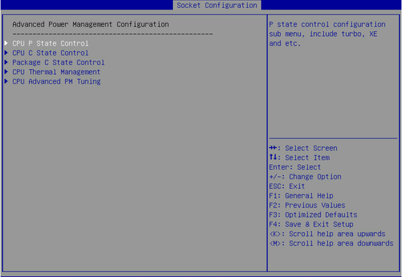
Table 3-60 Items on the Advanced Power Management Configuration submenu screen
|
Item |
Description |
|
CPU P State Control |
Submenu for configuring CPU P-state control options, as shown in Figure 3-72. On the submenu, you can select whether to enable Enhanced Intel SpeedStep Technology (EIST) and turbo mode as described in Table 3-61. |
|
CPU C State Control |
Submenu for configuring CPU C-state control options, as shown in Figure 3-73. On the submenu, you can control the power consumption of CPUs in idle state as described in Table 3-62. |
|
Package C State Control |
Submenu for configuring package C state control options, as shown in Figure 3-74. On the submenu, you can set the C2 to C3 state transition timer as described in Table 3-63. |
|
CPU Thermal Management |
Submenu for configuring CPU thermal management options, as shown in Figure 3-75. The submenu items are described in Table 3-64. |
|
CPU Advanced PM Tuning |
Submenu for configuring CPU advanced power management tuning, as shown in Figure 3-77. The submenu items are described in Table 3-66. |
Figure 3-72 CPU P State Control submenu screen

Table 3-61 Items on the CPU P State Control submenu screen
|
Description |
Default |
|
|
EIST (P-States) |
Select Enabled or Disabled to enable or disable Enhanced Intel SpeedStep Technology (EIST). EIST allows the system to automatically adjust processor voltage and core frequency to reduce power consumption and heat dissipation. |
Enabled |
|
Turbo Mode |
Select Enabled or Disabled to enable or disable Turbo mode. |
Enabled |
Figure 3-73 CPU C State Control submenu screen
Table 3-62 Items on the CPU C State Control submenu screen
|
Description |
Default |
|
|
Autonomous Core C-State |
Select Enabled or Disabled to enable or disable the autonomous core C-state. If this item is enabled, the hardware autonomously chooses to enter a C-state based on power consumption and clock speed. |
Disabled |
|
CPU C6 Report |
Select whether to enable the BIOS to report the C6 state to the operating system. Options: · Enabled. · Disabled. · Auto. |
Disabled |
|
Enhanced Halt State (C1E) |
Select Enabled or Disabled to enable or disable the C1E feature. C1E feature reduces the power consumption of a CPU by reducing its clock cycle and voltage during a Halt-state. |
Disabled |
Figure 3-74 Package C State Control submenu screen

Table 3-63 Items on the Package C State Control submenu screen
|
Item |
Description |
Default |
|
Package C State |
Select the package C state limit. Options: · Auto. · C0/C1 state. · C2 state. · C6 (non Retention) state. · C6 (Retention) state. · No Limit. |
C0/C1 state |
|
Set the C2 to C3 state transition timer. Value range: 0 to 255. If the timer is set to 0, the BIOS sets the timer automatically. |
0 |
Figure 3-75 CPU Thermal Management submenu screen

Table 3-64 Items on the CPU Thermal Management submenu screen
|
Item |
Description |
|
CPU T State Control |
CPU T-state control submenu, as shown in Figure 3-76 . The submenu items are described in Table 3-65. |
Figure 3-76 CPU T State Control submenu screen

Table 3-65 Items on the CPU T State Control submenu screen
|
Item |
Description |
Default |
|
Select Enabled or Disabled to enable or disable software controlled T-state. |
Disabled |
Figure 3-77 CPU Advanced PM Tuning submenu screen
Table 3-66 Items on the CPU Advanced PM Tuning submenu screen
|
Item |
Description |
|
Energy and performance bias configuration submenu, on which you can configure the energy and performance policy for the system, as shown in Figure 3-78. The submenu items are described in Table 3-67. |
Figure 3-78 Energy Perf BIAS submenu screen
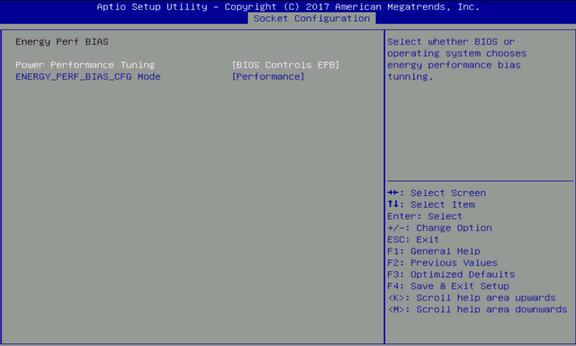
Table 3-67 Items on the Energy Perf BIAS submenu screen
|
Item |
Description |
Default |
|
Energy Performance Tuning |
Select the operating system or the BIOS to control energy and performance bias tuning. Options: · OS Controls EPB. |
BIOS Controls EPB |
|
ENERGY_PERF_BIAS_CFG Mode |
This item is available only when Energy Performance Tuning is set to BIOS Controls EPB. Select an energy and performance bias option. The setting for this option overrides the energy and performance bias configured by the operating system. Options: · Performance—Provides maximum system performance (maximum cooling) at the expense of energy efficiency. · Balanced Performance—Provides optimum performance with good energy efficiency. · Balanced Power—Provides optimum power efficiency with good performance. · Power—Provides maximum power efficiency (maximum power saving) at the expense of system performance. |
Performance |
Server Management menu
Figure 3-79 shows the Server Management menu, on which you can configure server management features such as the FRB-2 timer, OS watchdog timer, system event logging, and HDM.
The menu items are described in Table 3-41.
You can also access the firmware information submenu from the Server Management menu.
Figure 3-79 Server Management menu screen
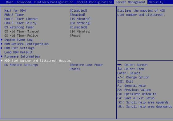
Table 3-68 Items on the Server Management menu screen
|
Item |
Description |
Default |
|
Wait for HDM |
Select Enabled or Disabled to enable or disable the wait for HDM feature. |
Disabled |
|
FRB-2 Timer |
Select Enabled or Disabled to enable or disable the FRB-2 timer. |
Enabled |
|
FRB-2 Timer Timeout |
Set the timeout time for the FRB-2 timer. Options: · 3 Minutes. · 4 Minutes. · 5 Minutes. · 6 Minutes. · 10 Minutes. · 15 Minutes. · 20 Minutes. |
15 Minutes |
|
FRB-2 Timer Policy |
Select the action to take when the FRB-2 timer expires. Options: · Do Nothing—No action is taken. · Reset—Reboot the system. · Power Down—Removes the main power from the system. · Power Cycle—Power cycles the system. |
Do Nothing |
|
OS Watchdog Timer |
Select Enabled or Disabled to enable or disable the OS watchdog timer. The OS watchdog timer starts when the operating system begins to run. |
Disabled |
|
OS Wtd Timer Timeout |
This item is configurable only when OS Watchdog Timer is set to Enabled. Set the timeout time for the OS watchdog timer. Options: · 5 Minutes. · 10 Minutes. · 15 Minutes. · 20 Minutes. |
10 Minutes |
|
This item is configurable only when OS Watchdog Timer is set to Enabled. Select the action to take when the OS watchdog timer expires. Options: · Do Nothing—No action is taken. · Reset—Reboots the system. · Power Down—Removes the main power from the system. · Power Cycle—Power cycles the system. |
Reset |
|
|
System Event Log |
Access the submenu for configuring system event logging, as shown in Figure 3-80. The submenu items are described in Table 3-69. |
N/A |
|
HDM Network Configuration |
Access the network configuration submenu for HDM access, as shown in Figure 3-82. The submenu items are described in Table 3-70. |
N/A |
|
HDM User Settings |
Access the submenu for managing HDM user accounts, as shown in Figure 3-83. The submenu items are described in Table 3-71. |
N/A |
|
Load HDM Default |
Restore the factory default settings for HDM.
The restoration process takes about 30 seconds. Do not configure any HDM settings before the server restarts. |
N/A |
|
Firmware Information |
Access the submenu that displays the firmware information, as shown in Figure 3-86. The submenu items are described in Table 3-75. |
N/A |
|
HDD Slot Number and Silkscreen Mapping |
Access the submenu that displays drive slot numbers and their corresponding silkscreens, as shown in Figure 3-87 and Figure 3-88. The submenu items are described in Table 3-76. |
N/A |
|
Select the power-on policy of the server when the server is connected to the power source. Options: · Always Power On—Enables the server to automatically start up when it is connected to the power source. · Always Remain Off—Disables the server from automatically start up when it is connected to the power source. · Restore Last Power State—Enables the server to return to the power state on the previous power-off. You can configure the power-on policy from the BIOS and HDM. The configuration in HDM takes precedence over the configuration in the BIOS. |
Restore Last Power State |
Figure 3-80 System Event Log submenu screen
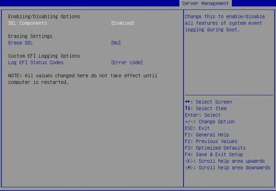
Table 3-69 Items on the System Event Log submenu screen
|
Item |
Description |
Default |
|
Enabling/Disabling Options |
||
|
SEL Components |
Select Enabled or Disabled to enable or disable system event logging. |
Enabled |
|
Erasing Settings |
||
|
Erase SEL |
This item is available only when SEL Components is set to Enabled. Select a system event log erasure option. Options: · No—Disable automatic system event log erasure. · Yes, On next reset—Erases the system event log only at next reboot. · Yes, On every reset—Erases the system event log at each reboot. |
No |
|
Custom EFI Logging Options |
||
|
Log EFI Status Codes |
This item is available only when SEL Components is set to Enabled. Configure EFI status code logging. Options: · Disabled—Disables logging EFI status codes. · Both—Logs both EFI error codes and progress codes. · Error Code—Logs only EFI error codes. · Progress Code—Logs only EFI progress codes. |
Error Code |
Figure 3-81 HDM Network Configuration submenu
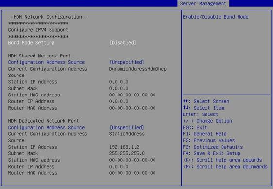
Table 3-70 Items on the HDM Network Configuration submenu screen
|
Item |
Description |
Default |
|
Bond Mode Setting |
Select Enabled or Disabled to enable or disable HDM network port bonding. HDM network port bonding aggregates the HDM dedicated network port and the shared network port into a bond port. The bond port uses the IP address setting of the dedicated network port. After you enable HDM network port bonding, the HDM Network Configuration submenu displays only the HDM bonding network port information, and the BIOS setup page displays only the IP address of the HDM bond port. |
Disabled |
|
Configuration Address Source |
Select the IP address obtaining method for the port. Options: · Unspecified—Uses the current IP address obtaining method and settings. · Static—Uses the manually configured static IP address. · DynamicHdmDhcp—Obtains an IP address from a DHCP server. |
Unspecified |
|
Current Configuration Address Source |
Displays the current IP address obtaining method. |
N/A |
|
Station IP Address |
Displays the IP address of the port. |
N/A |
|
Subnet Mask |
Displays the subnet mask. |
N/A |
|
Station MAC address |
Displays the MAC address of the port. |
N/A |
|
Router IP Address |
Displays the gateway IP address. |
N/A |
|
Router MAC Address |
Displays the gateway MAC address. |
N/A |
Figure 3-82 HDM User Settings submenu screen
Table 3-71 Items on the HDM User Settings submenu screen
|
Item |
Description |
|
Add User |
Submenu for adding an HDM user account, as shown in Figure 3-83. The submenu items are described in Table 3-72. |
|
Delete User |
Submenu for deleting an HDM user account, as shown in Figure 3-84. The submenu items are described in Table 3-73. |
|
Change User Settings |
Submenu for changing the settings of an existing HDM user account, as shown in Figure 3-85 . The submenu items are described in Table 3-74. |
Figure 3-83 Add User submenu screen
Table 3-72 Items on the Add User submenu screen
|
Item |
Description |
Default |
|
Specify the username, a case-sensitive string of 1 to 16 characters. The user name can contain letters, digits, and underscores (_). |
N/A |
|
|
User Password |
If password complexity check is enabled on the HDM Web interface, the password must meet the following requirements: · 8 to 20 characters in length. · Case sensitive. Valid characters are letters, digits, spaces, and the following special characters: ` ~ ! @ # $ % ^ & * ( ) _ + - = [ ] \ { } | ; ' : " , . / < > ? · Must contain characters from at least two of the following categories: uppercase letters, lowercase letters, and digits. · Must contain at least one space or special character. · Must not be identical to the user name or the reverse of the username. If password complexity check is disabled on the HDM Web interface, the password must meet the following requirements: · 2 to 20 characters in length. · Case sensitive. Valid characters are letters, digits, spaces, and the following special characters: ` ~ ! @ # $ % ^ & * ( ) _ + - = [ ] \ { } | ; ' : " , . / < > ? By default, password complexity check is enabled on the HDM Web interface. For more information about enabling or disabling password complexity check, see HDM online help. |
N/A |
|
User Privilege Limit |
Select a user role, which represents a set of network and service access privileges. Options: · None—Does not assign any network access permissions to the HDM user account. · User—Assigns the user the read-only permission to HDM. · Operator—Assigns the user the read permission to all HDM features and write permission to a limited set of HDM features. · Administrator—Assigns the user read and write permissions to all HDM features. |
None |
|
Access to HDM |
Select whether to enable HDM access for the HDM user account. Options: · Enabled. · Disabled. · Default—Retains the saved setting. |
Default |
Figure 3-84 Delete User submenu screen
Table 3-73 Items on the Delete User submenu screen
|
Item |
Description |
|
User Name |
Enter the username of the HDM user account to be deleted. |
|
User Password |
Enter the password of the HDM user account to be deleted. |
Figure 3-85 Change User Settings submenu screen
Table 3-74 Items on the Change User Settings submenu screen
|
Item |
Description |
Default |
|
User Name |
Enter the username of an existing HDM user account. |
N/A |
|
User Password |
Enter the password of the HDM user account. |
N/A |
|
Access to HDM |
This item is available only after you specify the correct user name and password for a user account. Select whether to enable HDM access for the user account. Options: · Enabled. · Disabled. · Default—Retains the saved setting. |
Default |
|
Change User Password |
This item is available only after you specify the correct user name and password for an HDM user account. Specify a new password. The password must meet the complexity requirements described in Table 3-72. |
N/A |
|
User Privilege Limit |
This item is available only after you specify the correct user name and password of an HDM user account. Assign role-based privileges to the user account. Options: · None—Retains the current privileges of the user account. · User—Assigns the user the read-only permission to HDM. · Operator—Assigns the user the read permission to all HDM features and write permission to a limited set of HDM features. · Administrator—Assigns the user read and write permissions to all HDM features. |
None |
Figure 3-86 Firmware Information submenu screen
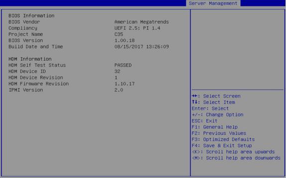
Table 3-75 Items on the Firmware Information submenu screen
|
Item |
Description |
|
BIOS Information |
|
|
BIOS Vendor |
Displays the BIOS vendor. |
|
Compliancy |
Displays the standard with which the BIOS is compliant. |
|
Project Name |
Displays the project name. |
|
BIOS Version |
Displays the BIOS version. |
|
Build Date and Time |
Displays the date and time of the BIOS build. |
|
HDM Information |
|
|
HDM Self Test Status |
Displays the HDM self test status. |
|
HDM Device ID |
Displays the HDM device ID. |
|
HDM Device Revision |
Displays the HDM device revision. |
|
HDM Firmware Revision |
Displays the HDM firmware revision. |
|
IPMI Version |
Displays the IPMI version. |
Figure 3-87 HDD Slot Number and Silkscreen Mapping submenu screen (1)
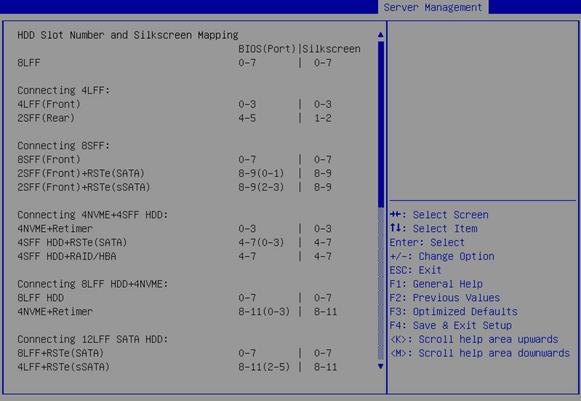
Figure 3-88 HDD Slot Number and Silkscreen Mapping submenu screen (2)
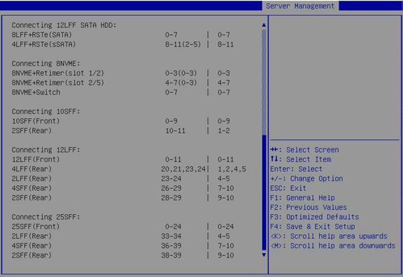
Table 3-76 Items on the HDD Slot Number and Silkscreen Mapping submenu screen
|
Item |
Description |
|
BIOS(Port) |
Displays the drive slot numbers in the BIOS. |
|
Silkscreen |
Displays the silkscreens on drives. |
|
Connecting 8SFF |
|
|
2SFF(Front)+RSTe(SATA) |
Indicates the two front-installed SFF drives controlled by the embedded RSTe RAID controller. SATA indicates drive slot numbers displayed on the PCH SATA Configuration screen. |
|
2SFF(Front)+RSTe(sSATA) |
Indicates the two front-installed SFF drives controlled by the embedded RSTe RAID controller. sSATA indicates drive slot numbers displayed on the PCH sSATA Configuration screen. |
|
Connecting 4NVME+4SFF HDD |
|
|
4NVME+Retimer |
Indicates the four NVMe SSDs controlled by the 4-port NVMe expander module (Retimer). |
|
4SFF HDD+RSTe(SATA) |
Indicates the four SFF HDDs controlled by the embedded RSTe RAID controller. SATA indicates drive slot numbers displayed on the PCH SATA Configuration screen. |
|
4SFF HDD+RAID/HBA |
Indicates the four SFF HDDs controlled by the RAID or HBA controller. |
|
Connecting 8LFF HDD+4NVME |
|
|
4NVME+Retimer |
Indicates the four NVMe SSDs controlled by the 4-port NVMe expander module (Retimer). |
|
Connecting 12LFF SATA HDD |
|
|
8LFF+RSTe(SATA) |
Indicates the eight LFF HDDs controlled by the embedded RSTe RAID controller. SATA indicates drive slot numbers displayed on the PCH SATA Configuration screen. |
|
4LFF+RSTe(sSATA) |
Indicates the four LFF drives controlled by the embedded RSTe RAID controller. sSATA indicates drive slot numbers displayed on the PCH sSATA Configuration screen. |
|
Connecting 8NVME |
|
|
8NVME+Retimer (slot 1/2) |
Indicates the four NVMe SSDs controlled by the 4-port NVMe expander module (Retimer) installed in PCIe slot 1 or 2. For a 1U server, the expander module is installed in PCIe slot 1. For a 2U server, the expander module is installed in PCIe slot 2. |
|
8NVME+Retimer (slot 2/5) |
Indicates the four NVMe SSDs controlled by the 4-port NVMe expander module (Retimer) installed in PCIe slot 2 or 5. For a 1U server, the expander module is installed in PCIe slot 2. For a 2U server, the expander module is installed in PCIe slot 5. |
|
8NVME+Switch |
Indicates the eight NVMe SSDs controlled by the 8-port NVMe expander module (Switch). |
|
|
NOTE: For the mapping relations between logic PCH SATA ports and drive backplane ports, see "Mapping relations of PCH SATA/sSATA ports and drive backplane ports." |
Security menu
Figure 3-89 shows the Security menu, on which you can configure security features such as setting the BIOS administrator and user passwords.
The menu items are described in Table 3-77.
Figure 3-89 Security menu screen
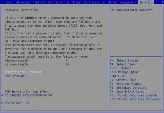
Table 3-77 Items on the Security menu screen
|
Item |
Description |
Default |
|
Password Description |
Displays the password description. |
N/A |
|
Administrator Password |
Set the administrator password. If you access the BIOS with the administrator password, you have full access to the BIOS. |
Empty |
|
User Password |
Set the user password. If you access the BIOS with the user password, you have limited access to the BIOS. Table 3-78 shows the submenus and submenu items that are inaccessible with the user password. |
Empty |
|
HDD Security Configuration: Hard disk drive that supports security configuration, for example, P3:SAMSUNG MZ7LM240HCGR-00005 |
If the server contains hard disk drives that support security configuration, this item is displayed and the hard disk drives are listed. Access the submenu for configuring security settings for a hard disk drive, as shown in Figure 3-90. The submenu items are described in Table 3-79. |
N/A |
|
Secure Boot Menu |
This item is available only in UEFI boot mode. Access the submenu for configuring secure boot, as shown in Figure 3-91. The submenu items are described in Table 3-80. |
N/A |
Table 3-78 BIOS submenus and submenu items inaccessible with the user password
|
Level-2 submenu |
Submenu items |
|
|
Advanced |
ACPI Settings |
Enable ACPI Auto Configuration |
|
Lock Legacy Resources |
||
|
PCI Subsystem Settings |
Above 4G Decoding |
|
|
SR-IOV Support |
||
|
USB Configuration |
Legacy USB Support |
|
|
XHCI Hand-off |
||
|
USB Mass Storage Device Support |
||
|
Server Mgmt |
Wait for HDM |
|
|
FRB-2 Timer |
Entire submenu inaccessible |
|
|
FRB-2 Timer Timeout |
Entire submenu inaccessible |
|
|
FRB-2 Timer Policy |
Entire submenu inaccessible |
|
|
OS Watchdog Timer |
Entire submenu inaccessible |
|
|
OS Wtd Timer Timeout |
Entire submenu inaccessible |
|
|
OS Wtd Timer Policy |
Entire submenu inaccessible |
|
|
System Event Log |
Entire submenu inaccessible |
|
|
HDM Network Configuration |
Entire submenu inaccessible |
|
|
HDM User Settings |
Entire submenu inaccessible |
|
|
Security |
Administrator Password |
Entire submenu inaccessible |
|
Secure Boot Menu |
System Mode |
|
|
Secure Boot |
||
|
Vendor Keys |
||
|
Attempt Secure Boot |
||
|
Secure Boot Mode |
||
|
Key Management |
Figure 3-90 HDD Security Configuration submenu screen
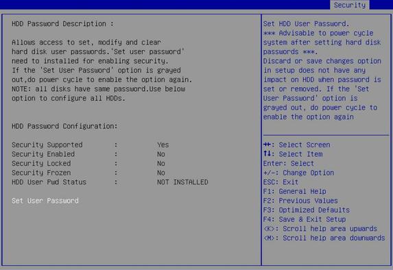
Table 3-79 Items on the HDD Security Configuration submenu screen
|
Item |
Description |
|
Security Supported |
Displays whether the hard disk drive supports security configuration. |
|
Security Enabled |
Displays whether an HDD user password has been set. If an HDD user password has been set, you must provide the password to unlock the hard disk drive before using it. |
|
Security Locked |
Displays whether the hard disk drive is locked. If the hard disk drive is locked, enter the user password to unlock it. |
|
Security Frozen |
Displays the security frozen status. Options: · Yes—The hard disk drive can be used but you cannot configure a user password for it. To change the security frozen status to No, you must power cycle the server. · No—The hard disk drive is not frozen. You can set the HDD user password. |
|
HDD User Pwd Status |
Displays whether an HDD user password is set (Installed) or not (Not Installed.) |
|
Set User Password |
Set an HDD user password, a case-sensitive string of 1 to 32 characters which can contain letters, digits, spaces, and the following special characters: ` ~ ! @ # $ % ^ & * ( ) _ + - = [ ] \ { } | ; ' : " , . / < > ? Store the HDD user password in a safe place. You will be asked to enter the password during server startup. The hard disk drive will be locked on three consecutive password attempt failures. |
Figure 3-91 Secure Boot Menu submenu screen
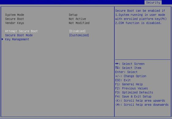
Table 3-80 Items on the Secure Boot menu screen
|
Item |
Description |
Default |
|
System Mode |
Displays the system mode. |
N/A |
|
Secure Boot |
Displays whether secure boot is active or inactive. |
N/A |
|
Vendor Keys |
Displays whether the vendor keys have been modified. |
N/A |
|
Attempt Secure Boot |
Select Enabled or Disabled to enable or disable secure boot. Secure boot can be enabled only when the following requirements are met: · The system is in user mode and the platform key is installed. · The CSM Support item on the CSM Configuration menu is set to Disabled. |
Disabled |
|
Secure Boot Mode |
Select a secure boot mode. Options: · Standard. · Customized. In customized boot mode, you can change the image execution policy and manage secure boot keys. |
Customized |
|
Key Management |
Access the submenu for key management, as shown in Figure 3-92. The submenu items are described in Table 3-81. |
N/A |
Figure 3-92 Key Management submenu screen
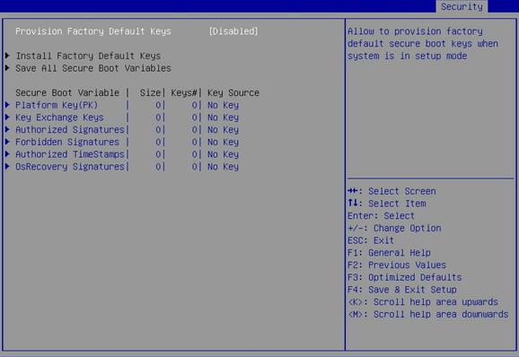
Table 3-81 Items on the Key Management submenu screen
|
Item |
Description |
Default |
|
Provision Factory Default Keys |
Select Enabled or Disabled to enable or disable provisioning the factory default keys when the system is in setup mode. |
Disabled |
|
Install Factory Default Keys |
Install all factory default keys. When factory default key installation is complete, this item changes to Reset all Secure Boot Variables. |
N/A |
|
Save All Secure Boot Variables |
Save all secure boot variables. |
N/A |
|
Platform Key(PK) |
Access the submenu for managing the platform key. You can select Set New Var to set a new key. |
N/A |
|
Key Exchange Keys |
Access the submenu for managing key exchange keys. Options: · Set New Var. · Append Key. |
N/A |
|
Authorized Signatures |
Access the submenu for configuring authorized signatures. Options: · Set New Var. · Append Key. |
N/A |
|
Forbidden Signatures |
Access the submenu for managing forbidden signatures. Options: · Set New Var. · Append Key. |
N/A |
|
Authorized TimeStamps |
Access the submenu for managing authorized timestamps. Options: · Set New Var. · Append Key. |
N/A |
|
OsRecovery Signatures |
Access the submenu for configuring operating system recovery signatures. Options: · Set New Var. · Append Key. |
N/A |
Boot menu
Figure 3-93 shows the Boot menu, on which you can configure boot settings such as the boot type and boot sequence.
The menu items are described in Table 3-82.
Figure 3-93 Boot menu screen
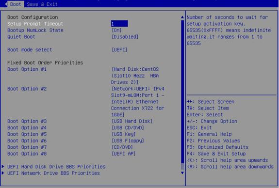
Table 3-82 Items on the Boot menu screen
|
Item |
Description |
Default |
|
Setup Prompt Timeout |
Set the number of seconds to wait for the setup activation key. Value range: 1 to 65535. |
1 |
|
Bootup NumLock State |
Select On or Off to turn on or turn off the NumLock key on the numeric keypad of the keyboard at system boot. |
On |
|
Quiet Boot |
Select Enabled or Disabled to enable or disable the quiet boot mode. |
Disabled |
|
Boot mode Select |
Select a boot mode. Options: · Legacy. · UEFI. |
UEFI |
|
This item allows you to set a prioritized list of bootable devices from which the system can boot. Select each boot option (Boot Option #N) to specify a bootable device, as shown in Figure 3-94 . The lower the option number, the higher the priority. In legacy mode, a drive is eligible for selection only if it has the highest boot priority (BBS priority) among all the drives of the same type. Boot Option #9 is available only in UEFI boot mode. |
N/A |
|
|
UEFI Hard Disk Drive BBS Priorities |
This item is available only in UEFI boot mode. Access the submenu for configuring the boot priorities of hard disk drives, as shown in Figure 3-95 . |
N/A |
|
Hard Disk Drive BBS Priorities |
This item is available only in legacy boot mode. Access the submenu for configuring the boot priorities of hard disk drives. |
N/A |
|
UEFI CDROM/DVD Drive BBS Priorities |
This item is available only in UEFI boot mode and when one or more CD- or DVD-ROM drives are connected. Access the submenu for configuring the boot priorities of connected CD- or DVD-ROM drives, as shown in Figure 3-96 . The submenu items are described in Table 3-84. |
N/A |
|
CDROM/DVD Drive BBS Priorities |
This item is available only in legacy boot mode and when one or more CD- or DVD-ROM drives are connected. Access the submenu for configuring the boot priorities of connected CD- or DVD-ROM drives. |
N/A |
|
UEFI USB Hard Disk Drive BBS Priorities |
This item is available only in UEFI boot mode and when one or more hard disk drives are connected through USB interfaces. Access the submenu for configuring the boot priorities of hard disk drives connected through USB interfaces, as shown in Figure 3-97 . The submenu items are described in Table 3-85. |
N/A |
|
USB Hard Disk Drive BBS Priorities |
This item is available only in legacy boot mode and when one or more hard disk drives are connected through USB interfaces. Access the submenu for configuring the boot priorities of hard disk drives connected through USB interfaces. |
N/A |
|
UEFI USB CDROM/DVD Drive BBS Priorities |
This item is available only in UEFI boot mode and when one or more CD- or DVD-ROM drives are connected through USB interfaces. Access the submenu for configuring the boot priorities of CD- or DVD-ROM drives connected through USB interfaces, as shown in Figure 3-98 . The submenu items are described in Table 3-86. |
N/A |
|
USB CDROM/DVD Drive BBS Priorities |
This item is available only in legacy boot mode and when one or more CD- or DVD-ROM drives are connected through USB interfaces. Access the submenu for configuring the boot priorities of CD- or DVD-ROM drives connected through USB interfaces. |
N/A |
|
UEFI USB Key Drive BBS Priorities |
This item is available only in UEFI boot mode and when one or more USB key drives are connected. Access the submenu for configuring the boot priorities of connected USB key drives. |
|
|
USB Key Drive BBS Priorities |
This item is available only in legacy boot mode and when one or more USB key drives are connected. Access the submenu for configuring the boot priorities of connected USB key drives. |
N/A |
|
UEFI USB Floppy Drive BBS Priorities |
This item is available only in UEFI boot mode and when one or more floppy drives are connected through USB interfaces. Access the submenu for configuring the boot priorities of the floppy drives connected through USB interfaces. |
N/A |
|
USB Floppy Drive BBS Priorities |
This item is available only in legacy boot mode and when one or more floppy drives are connected through USB interfaces. Access the submenu for configuring the boot priorities of floppy drives connected through USB interfaces. |
N/A |
|
UEFI Network Drive BBS Priorities |
This item is available only in UEFI boot mode. Access the submenu for configuring the boot priorities of available network drives. |
N/A |
|
Network Drive BBS Priorities |
This item is available only in legacy boot mode. Access the submenu for configuring the boot priorities of available network drives. |
N/A |
|
UEFI Application Boot Priorities |
This item is available only in UEFI boot mode. Access the submenu for configuring UEFI application boot priorities. |
N/A |
Figure 3-94 Setting the prioritized list of bootable devices
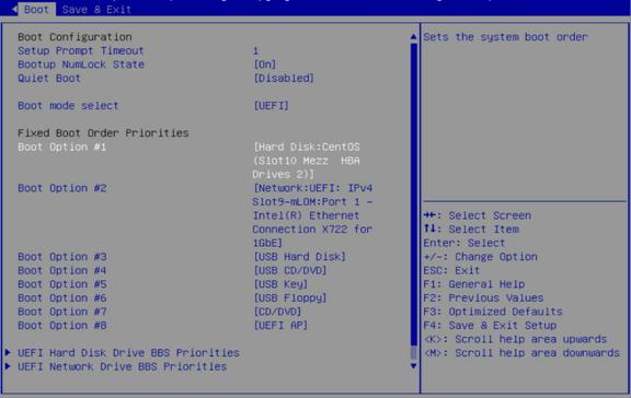
Figure 3-95 UEFI Hard Disk Drive BBS Priorities submenu screen
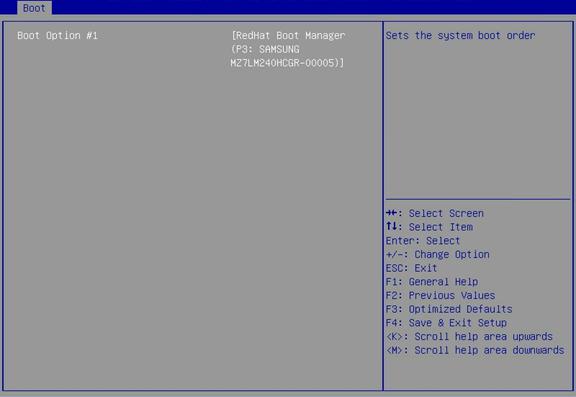
Table 3-83 Items on the UEFI Hard Disk Drive BBS Priorities submenu screen
|
Item |
Description |
|
Boot Option #1 |
Select a hard disk drive as the first boot option. |
|
Boot Option #2 |
Select a hard disk drive as the second boot option. |
Figure 3-96 UEFI CDROM/DVD Drive BBS Priorities submenu screen
Table 3-84 Items on the UEFI CDROM/DVD Drive BBS Priorities submenu screen
|
Item |
Description |
|
Boot Option #1 |
Select a CD- or DVD-ROM drive as the first boot option. |
Figure 3-97 UEFI USB Hard Disk Drive BBS Priorities submenu screen
Table 3-85 Items on the UEFI USB Hard Disk Drive BBS Priorities submenu screen
|
Item |
Description |
|
Boot Option #1 |
Select a hard disk drive connected through a USB interface as the first boot option. |
Figure 3-98 UEFI USB CDROM/DVD Drive BBS Priorities submenu screen
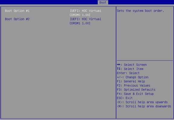
Table 3-86 Items on the UEFI USB CDROM/DVD Drive BBS Priorities submenu screen
|
Item |
Description |
|
Boot Option #1 |
Select a CD- or DVD-ROM drive connected through a USB device as the first boot option. |
|
Boot Option #2 |
Select a CD- or DVD-ROM drive connected through a USB device as the second boot option. |
Figure 3-99 UEFI USB Key Drive BBS Priorities submenu screen
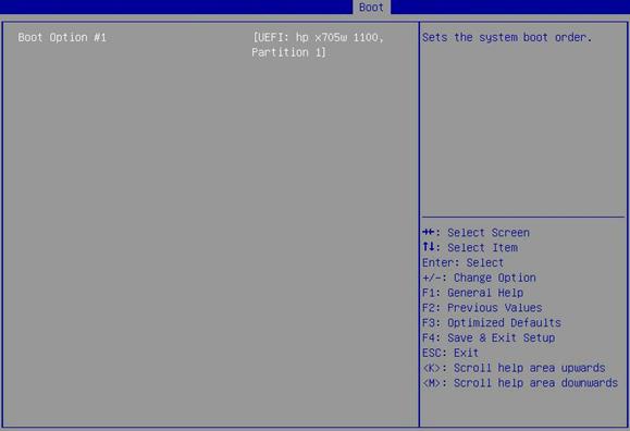
Table 3-87 Items on the UEFI USB Key Drive BBS Priorities submenu screen
|
Items |
Description |
|
Boot Option #1 |
Select a USB key drive as the first boot option. |
Figure 3-100 EFI USB Floppy Drive BBS Priorities submenu screen
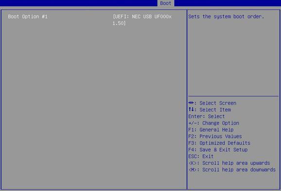
Table 3-88 Items on the UEFI USB Floppy Drive BBS Priorities submenu screen
|
Item |
Description |
|
Boot Option #1 |
Select a floppy drive connected through a USB interface as the first boot option. |
Figure 3-101 UEFI Network Drive BBS Priorities submenu screen
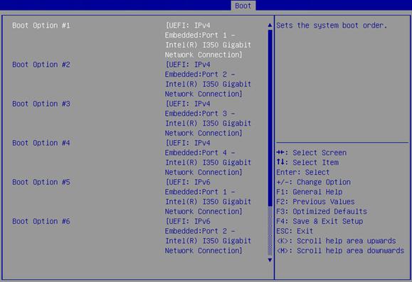
Table 3-89 Items on the UEFI Network Drive BBS Priorities submenu screen
|
Item |
Description |
|
Boot Option #1 |
Select an available network drive as the first boot option. |
|
Select an available network drive as the second boot option. |
|
|
Boot Option #3 |
Select an available network drive as the third boot option. |
|
Boot Option #4 |
Select an available network drive as the fourth boot option. |
|
Boot Option #5 |
Select an available network drive as the fifth boot option. |
|
Boot Option #6 |
Select an available network drive as the sixth boot option. |
|
Boot Option #7 |
Select an available network drive as the seventh boot option. |
|
Boot Option #8 |
Select an available network drive as the eighth boot option. |
Figure 3-102 UEFI Application Boot Priorities submenu screen
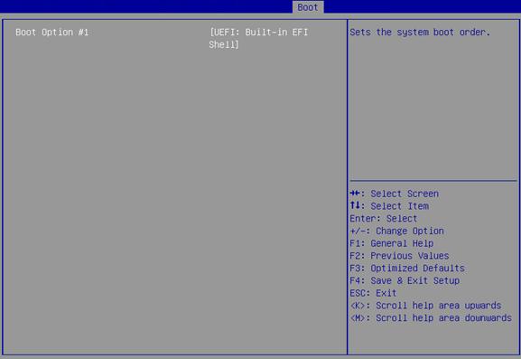
Table 3-90 Items on the UEFI Application Boot Priorities submenu screen
|
Item |
Description |
|
Boot Option #1 |
Select a UEFI application as the first boot option. |
Save & Exit menu
Figure 3-103 shows the Save & Exit menu, on which you can save the BIOS parameter settings and exit BIOS.
The menu items are described in Table 3-91.
Figure 3-103 Save & Exit menu screen

Table 3-91 Items on the Save & Exit menu screen
|
Item |
Description |
|
Save Options |
|
|
Exit with changes saved. |
|
|
Discard Changes and Exit |
Exit without saving changes. |
|
Save Changes and Reset |
Restart the server with changes saved. |
|
Discard Changes and Reset |
Restart the server without saving changes. |
|
Save Changes |
Save changes without exiting the BIOS. |
|
Discard Changes |
Discard changes without exiting the BIOS. |
|
Default Options |
|
|
Restore Defaults |
Restore the factory-default settings. |
|
Select a boot device option and press Enter to boot from that device. This setting is a one-time setting that takes effect only at next boot. Subsequent boots will use the boot order configured on the Boot menu screen. If you have not saved changes, a Save & Reset dialog box will open after you select a boot option for Boot Override. · To save the changes and reboot the server, select Yes. · To cancel the reboot, select No. NOTE: In legacy boot mode, a drive is eligible to be a boot option for Boot Override only if it has the highest priority (BBS priority) among all drives of the same type. |
|
4 Mapping relations of PCH SATA/sSATA ports and drive backplane ports
This chapter describes the mapping relations of PCH SATA/sSATA ports on the system board and ports on the drive backplane connected by data cables when the embedded RAID controller is used. If only a mezzanine or standard storage controller is used, data cables connect ports on the drive backplane to the storage controller, instead of PCH SATA/sSATA ports on the system board.
H3C UniServer R4900 G3 server
8LFF HDDs
|
Storage controller |
PCH SATA/sSATA ports on the system board |
Ports on the drive backplane |
|
Embedded RSTe RAID controller |
PCH mini-SAS HD J11 port (logic SATA ports 0 through 7) |
Ports 0 through 7 |
8LFF HDDs and 4LFF NVMe SSDs
|
Storage controller |
PCH SATA/sSATA ports on the system board |
Ports on the drive backplane |
|
|
Embedded RSTe RAID controller + 4-port NVMe expander module (4-port NVMe expander module in PCIe slot 2) |
8LFF HDDs (embedded RSTe RAID controller) |
PCH mini-SAS HD J11 port (logic SATA ports 0 through 7) |
Ports 0 through 7 |
|
4LFF NVMe SSDs (4-port NVMe expander module) |
N/A |
N/A |
|
8SFF HDDs
|
Storage controller |
PCH SATA/sSATA ports on the system board |
Ports on the drive backplane |
|
Embedded RSTe RAID controller |
PCH mini-SAS HD J11 port (logic SATA ports 0 through 7) |
Ports 0 through 7 |
8SFF HDDs and 8SFF NVMe SSDs
|
Storage controller |
PCH SATA/sSATA ports on the system board |
Ports on the drive backplane |
|
|
Embedded RSTe RAID controller + 8-port NVMe expander module (expander module in PCIe slot 2) |
8SFF HDDs (embedded RSTe RAID controller) |
PCH mini-SAS HD J11 port (logic SATA ports 0 through 7) |
Ports 0 through 7 |
|
8SFF NVMe SSDs (8-port NVMe expander module) |
N/A |
N/A |
|
|
Embedded RSTe RAID controller + 4-port NVMe expander modules (expander modules in PCIe slots 2 and 5) |
8SFF HDDs (embedded RSTe RAID controller) |
PCH mini-SAS HD J11 port (logic SATA ports 0 through 7) |
Ports 0 through 7 |
|
8SFF NVMe SSDs (4-port NVMe expander modules) |
N/A |
N/A |
|
H3C UniServer R4700 G3 server
4LFF HDDs
|
Storage controller |
PCH SATA/sSATA ports on the system board |
Ports on the drive backplane |
|
Embedded RSTe RAID controller |
PCH mini-SAS HD J11 port (logic SATA ports 0 through 3) |
Ports 0 through 3 |
4LFF HDDs and 2SFF HDDs
|
Storage controller |
PCH SATA/sSATA ports on the system board |
Ports on the drive backplane |
|
|
Embedded RSTe RAID controller |
4LFF HDDs |
PCH mini-SAS HD J11 port (logic SATA ports 0 through 3) |
Ports 0 through 3 |
|
2SFF HDDs |
PCH mini-SAS HD J11 port (logic SATA ports 4 and 5) |
Ports 4 and 5 |
|
4SFF NVMe SSDs and 4SFF HDDs
|
Storage controller |
PCH SATA/sSATA ports on the system board |
Ports on the drive backplane |
|
|
Embedded RSTe RAID controller + 4-port NVMe expander module (expander module in PCIe slot 1) |
4SFF HDDs (embedded RSTe RAID controller) |
PCH mini-SAS HD J11 port (logic SATA ports 0 through 3) |
Ports 4 through 7 |
|
4SFF NVMe SSDs (4-port NVMe expander module) |
N/A |
N/A |
|
8SFF HDDs
|
Storage controller |
PCH SATA/sSATA ports on the system board |
Ports on the drive backplane |
|
Embedded RSTe RAID controller |
PCH mini-SAS HD J11 port (logic SATA ports 0 through 7) |
Ports 0 through 7 |
8SFF HDDs and 2SFF HDDs
|
Storage controller |
PCH SATA/sSATA ports on the system board |
Ports on the drive backplane |
|
|
Embedded RSTe RAID controller + Mezzanine storage controller |
2SFF HDDs (embedded RSTe RAID controller) |
PCH mini-SAS HD J11 port (logic SATA ports 0 and 1) |
Ports 8 and 9 |
|
8SFF HDDs (Mezzanine storage controller) |
N/A |
N/A |
|
|
Embedded RSTe RAID controller + standard storage controller (standard storage controller in PCIe slot 1) |
2SFF HDDs (embedded RSTe RAID controller) |
PCH mini-SAS HD J11 port (logic SATA ports 0 and 1) |
Ports 8 and 9 |
|
8SFF HDDs (standard storage controller) |
N/A |
N/A |
|
8SFF NVMe SSDs and 2SFF HDDs
|
Storage controller |
PCH SATA/sSATA ports on the system board |
Ports on the drive backplane |
|
|
Embedded RSTe RAID controller + 8-port NVMe expander module (expander module in PCIe slot 1) |
2SFF HDDs (embedded RSTe RAID controller) |
PCH mini-SAS HD J11 port (logic SATA ports 0 and 1) |
Ports 8 and 9 |
|
8SFF NVMe SSDs (8-port NVMe expander module) |
N/A |
N/A |
|
|
Embedded RSTe RAID controller + 4-port NVMe expander modules (expander modules in PCIe slots 1 and 2) |
2SFF HDDs (embedded RSTe RAID controller) |
PCH mini-SAS HD J11 port (logic SATA ports 0 and 1) |
Ports 8 and 9 |
|
8SFF NVMe SSDs (4-port NVMe expander modules) |
N/A |
N/A |
|
H3C UniServer R2900 G3 server
8LFF HDDs
|
Storage controller |
PCH SATA/sSATA ports on the system board |
Ports on the drive backplane |
|
PCH mini-SAS HD J11 port (logic SATA ports 0 through 7) |
Ports 0 through 7 |
12LFF HDDs
|
Storage controller |
PCH SATA/sSATA ports on the system board |
Ports on the drive backplane |
|
Embedded RSTe RAID controller |
PCH mini-SAS HD J11 port (logic SATA ports 0 through 7) |
Ports 0 through 7 |
|
PCH mini-SAS HD J12 port (logic sSATA ports 2 through 5) |
Ports 8 through 11 |
12LFF HDDs and 2SFF HDDs
|
Storage controller |
PCH SATA/sSATA ports on the system board |
Ports on the drive backplane |
|
Embedded RSTe RAID controller |
PCH mini-SAS HD J11 port (logic SATA ports 0 through 7) |
Ports 0 through 7 |
|
PCH mini-SAS HD J12 port (logic sSATA ports 2 through 5) |
Ports 8 through 11 |
|
|
PCH 7PIN SATA J13 port (logic sSATA ports 0 and 1) |
Ports 28 and 29 |
8LFF HDDs and 4LFF NVMe SSDs
|
Storage controller |
PCH SATA/sSATA ports on the system board |
Ports on the drive backplane |
|
|
Embedded RSTe RAID controller + 4-port NVMe expander module (expander module in PCIe slot 2) |
8LFF HDDs (embedded RSTe RAID controller) |
PCH mini-SAS HD J11 port (logic SATA ports 0 through 7) |
Ports 0 through 7 |
|
4LFF NVMe SSDs (expander module in PCIe slot 2) |
N/A |
||
8SFF HDDs
|
PCH SATA/sSATA ports on the system board |
Ports on the drive backplane |
|
|
Embedded RSTe RAID controller |
PCH mini-SAS HD J11 port (logic SATA ports 0 through 7) |
Ports 0 through 7 |
8SFF HDDs and 8SFF NVMe SSDs
|
Storage controller |
PCH SATA/sSATA ports on the system board |
Ports on the drive backplane |
|
|
Embedded RSTe RAID controller + 8-port NVMe expander module (expander module in PCIe slot 2) |
8SFF HDDs (embedded RSTe RAID controller) |
PCH mini-SAS HD J11 port (logic SATA ports 0 through 7) |
Ports 0 through 7 |
|
8SFF NVMe SSDs (8-port NVMe expander module) |
N/A |
N/A |
|
|
Embedded RSTe RAID controller + 4-port NVMe expander modules (expander modules in PCIe slots 2 and 5) |
8SFF HDDs (embedded RSTe RAID controller) |
PCH mini-SAS HD J11 port (logic SATA ports 0 through 7) |
Ports 0 through 7 |
|
8SFF NVMe SSDs (4-port NVMe expander modules) |
N/A |
N/A |
|
H3C UniServer R2700 G3 server
4LFF HDDs
|
Storage controller |
PCH SATA/sSATA ports on the system board |
Ports on the drive backplane |
|
Embedded RSTe RAID controller |
PCH mini-SAS HD J11 port (logic SATA ports 0 through 3) |
Ports 0 through 3 |
|
Mezzanine storage controller |
N/A |
N/A |
4LFF HDDs and 2SFF HDDs
|
Storage controller |
PCH SATA/sSATA ports on the system board |
Ports on the drive backplane |
|
|
Embedded RSTe RAID controller |
4LFF HDDs |
PCH mini-SAS HD J11 port (logic SATA ports 0 through 3) |
Ports 0 through 3 |
|
2SFF HDDs |
PCH mini-SAS HD J11 port (logic SATA ports 4 and 5) |
Ports 4 and 5 |
|
4SFF NVMe SSDs and 4SFF HDDs
|
Storage controller |
PCH SATA/sSATA ports on the system board |
Ports on the drive backplane |
|
|
Embedded RSTe RAID controller + 4-port NVMe expander module (expander module in PCIe slot 1) |
4SFF HDDs (embedded RSTe RAID controller) |
PCH mini-SAS HD J11 port (logic SATA ports 0 through 3) |
Ports 4 through 7 |
|
4SFF NVMe SSDs (4-port NVMe expander module) |
N/A |
N/A |
|
8SFF HDDs
|
Storage controller |
PCH SATA/sSATA ports on the system board |
Ports on the drive backplane |
|
Embedded RSTe RAID controller |
PCH mini-SAS HD J11 port (logic SATA ports 0 through 7) |
Ports 0 through 7 |
8SFF HDDs and 2SFF HDDs
|
Storage controller |
PCH SATA/sSATA ports on the system board |
Ports on the drive backplane |
|
|
Embedded RSTe RAID controller |
8SFF HDDs |
PCH mini-SAS HD J11 port (logic SATA ports 0 through 7) |
Ports 0 through 7 |
|
2SFF HDDs |
PCH mini-SAS HD J12 port (logic sSATA ports 2 and 3) |
Ports 8 and 9 |
|
|
Embedded RSTe RAID controller + Mezzanine storage controller |
2SFF HDDs (embedded RSTe RAID controller) |
PCH mini-SAS HD J12 port (logic sSATA ports 2 and 3) |
Ports 8 and 9 |
|
8SFF HDDs (Mezzanine storage controller) |
N/A |
N/A |
|
|
Embedded RSTe RAID controller + standard storage controller (standard storage controller in PCIe slot 1) |
2SFF HDDs (embedded RSTe RAID controller) |
PCH mini-SAS HD J12 port (logic sSATA ports 2 and 3) |
Ports 8 and 9 |
|
8SFF HDDs (standard storage controller) |
N/A |
N/A |
|
8SFF NVMe SSDs and 2SFF HDDs
|
Storage controller |
PCH SATA/sSATA ports on the system board |
Ports on the drive backplane |
|
|
Embedded RSTe RAID controller + 8-port NVMe expander module (expander module in PCIe slot 1) |
2SFF HDDs (embedded RSTe RAID controller) |
PCH mini-SAS HD J12 port (logic sSATA ports 2 and 3) |
Ports 8 and 9 |
|
8SFF NVMe SSDs (8-port NVMe expander module) |
N/A |
N/A |
|
|
Embedded RSTe RAID controller + 4-port NVMe expander modules (expander modules in PCIe slots 1 and 2) |
2SFF HDDs (embedded RSTe RAID controller) |
PCH mini-SAS HD J12 port (logic sSATA ports 2 and 3) |
Ports 8 and 9 |
|
8SFF NVMe SSDs (4-port NVMe expander modules) |
N/A |
N/A |
|
5 Acronyms and abbreviations
Table 5-1 Acronyms and abbreviations
|
Term |
Definition |
|
A |
|
|
ACPI |
Advanced Configuration and Power Interface |
|
AES |
Advanced Encryption Standard |
|
AHCI |
Advanced Host Controller Interface |
|
APIC |
Advanced Programmable Interrupt Controller |
|
B |
|
|
BIOS |
Basic Input Output System |
|
C |
|
|
COD |
Cluster On Die |
|
CFG |
Configure |
|
CSM |
Compatibility Support Module |
|
D |
|
|
DCU |
Drive Control Unit |
|
DMA |
Direct Memory Access |
|
DRAM |
Dynamic Random Access Memory |
|
E |
|
|
E2E |
End To End |
|
ECC |
Error Checking and Correcting |
|
EFI |
Extensible Firmware Interface |
|
EHCI |
Enhanced Host Controller Interface |
|
EIST |
Enhanced Intel SpeedStep Technology |
|
EMS |
Emergency Management Services |
|
EMCA |
Enhanced Machine Check Architecture |
|
G |
|
|
GPU |
Graphics Processing Unit |
|
H |
|
|
HBA |
Host Bus Adapter |
|
HDM |
H3C Device Management |
|
IDE |
Integrated Drive Electronics |
|
IIO |
Integrated I/O Module |
|
IMC |
Integrated Memory Controller |
|
IRQ |
Interrupt Request |
|
M |
|
|
MAC |
Media Access Control |
|
MCTP |
Management Component Transport Protocol |
|
ME |
Management Engine |
|
MMIO |
Memory mapping I/O |
|
MRC |
Memory Reference Code |
|
N |
|
|
NIC |
Network Interface Controller |
|
NMI |
Non-Maskable Interrupt |
|
NUMA |
Non Uniform Memory Access |
|
O |
|
|
OS |
Operating System |
|
PCH |
Platform Controller Hub |
|
PCI |
Peripheral Component Interface |
|
PCIe |
Peripheral Component Interconnect Express |
|
PCU |
Power Controller Unit |
|
PK |
Platform Key |
|
POR |
Plan Of Record |
|
POST |
|
|
PXE |
Preboot Execute Environment |
|
R |
|
|
RAID |
Redundant Arrays of Independent Disks |
|
RAPL |
Running Average Power Limit |
|
RAS |
Reliability, Availability, Serviceability |
|
RMT |
Rank Margin Tool |
|
ROM |
Read-Only Memory |
|
RTS/CTS |
Request To Send/Clear To Send |
|
S |
|
|
SAS |
Serial Attached SCSI |
|
SATA |
Serial Advanced Technology Attachment |
|
SCSI |
Small Computer System Interface |
|
SEL |
System Event Log |
|
SMI |
System Management Interrupt |
|
SPD |
Serial Presence Detect |
|
SR-IOV |
Single-Root I/O Virtualization |
|
T |
|
|
TCG |
Trusted Computing Group |
|
TDP |
Thermal Design Power |
|
TPM |
Trusted Platform Module |
|
TXT |
Trusted Execution Technologies |
|
U |
|
|
UEFI |
Unified Extensible Firmware Interface |
|
UID |
Unit Identification |
|
UPI |
Ultra Path Interconnect |
|
V |
|
|
VMD |
Volume Management Device |
|
VT-d |
Intel Virtualization Technology For Directed I/O |
|
VGA |
Video Graphics Array |
|
X |
|
|
eXtensible Host Controller Interface |
|