- Table of Contents
- Related Documents
-
| Title | Size | Download |
|---|---|---|
| 01-Text | 1.61 MB |
Temperature and humidity requirements
Determining the installation position
Connecting the AP to the power source
Connecting the PoE power supply
Connecting the local power supply
Connecting the AP to the network
Appendix A Technical specifications
Preparing for installation
Safety recommendations
|
|
WARNING! Only qualified personnel can install and remove the AP and its accessories. You must read all safety instructions before installation and operation. |
To avoid possible bodily injury and equipment damage, read the following safety recommendations before installing the AP. Note that the recommendations do not cover every possible hazardous condition.
· Take adequate safety measures to avoid body injury and device damage.
· Place the AP in a dry and flat location and take anti-slip measures.
· Keep the AP clean and dust-free.
· Do not place the AP in a moist area and avoid liquid intrusion.
· Keep the AP and installation tools away from walkways.
Temperature and humidity requirements
Table 1 Temperature and humidity requirements
|
Item |
Specification |
|
Operating temperature |
0°C to 45°C (32°F to 113°F) |
|
Storage temperature |
–40°C to +70°C (–40°F to +158°F) |
|
Operating humidity |
5% RH to 95% RH, noncondensing |
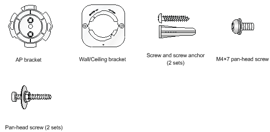
Installation accessories
Figure 1 Accessories provided with the AP
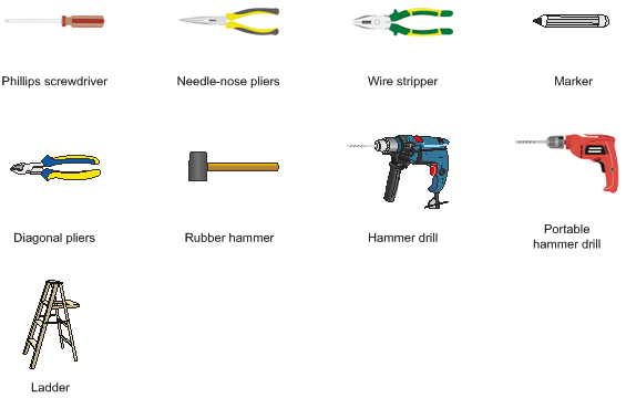
Installation tools
When installing the AP, you might need the following tools. Prepare the installation tools as required.
Figure 2 Installation tools
Installing the AP
Installation flowchart
Figure 3 Installation flowchart
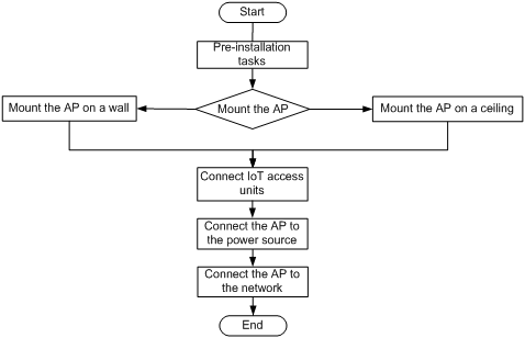
Pre-installation tasks
Before installing the AP, perform the following tasks:
· Connect the AP to a power source and the network. Examine the LEDs to verify that the AP operates correctly. For information about AP LEDs, see "LEDs."
· Record the MAC address and serial number at the rear of the AP for future use.
· Make sure you have completed cabling at the installation site.
Determining the installation position
Determine the installation position by observing the following principles:
· Few obstacles such as wall exist between the AP and clients.
· The AP is far away from electronic devices (such as microwave oven) that might generate radio frequency (RF) noise.
· The AP does not hinder people’s daily work and life.
· The place is not water seeping, water soaking, and condensing.
· The AP is more than 5 m (16.40 ft) away from 3G and 4G base stations and antennas.
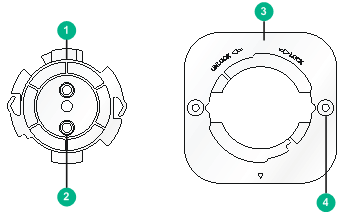
Mounting the AP
The AP can be installed only indoors. You can mount the AP on a wall or a ceiling.
The mounting bracket kit for the AP includes an AP bracket and a wall/ceiling bracket. To install the AP on a wall or ceiling, attach the AP bracket to the AP and the wall/ceiling bracket to the wall or ceiling.
|
(1) AP bracket |
(2) Alignment peg |
|
(3) Wall/Ceiling bracket |
(4) Installation hole |
Figure 5 Wall/Ceiling bracket installation holes
Mounting the AP on a wall
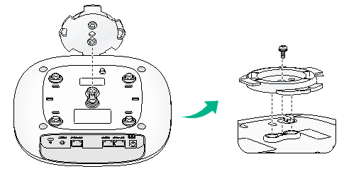
1. Set the alignment pegs on the AP bracket into the alignment holes in the AP rear. Use the M4 × 7 screw to secure the AP bracket to the AP through the installation hole in the middle of the AP bracket.
Figure 6 Attaching the AP bracket to the AP rear
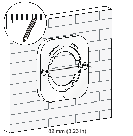
2. Mark the installation holes on the wall by using the wall/ceiling bracket, as shown in Figure 7.
Figure 7 Marking installation holes on the wall
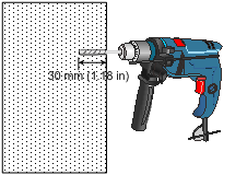
3. Drill holes with a diameter of 6 mm (0.24 in) and a depth of 30 mm (1.18 in) in the marked locations, as shown in Figure 8.
Figure 8 Drilling holes in the wall
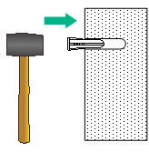
4. Insert a screw anchor into each hole, and tap the screw anchor with a rubber hammer until it is all flush with the wall surface, as shown in Figure 9.
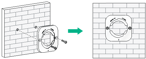
5. Align the installation holes in the wall/ceiling bracket with the anchors and insert screws through the installation holes into the screw anchors. Adjust the position of the wall/ceiling bracket and fasten the screws.
Figure 10 Attaching the wall/ceiling bracket to the wall
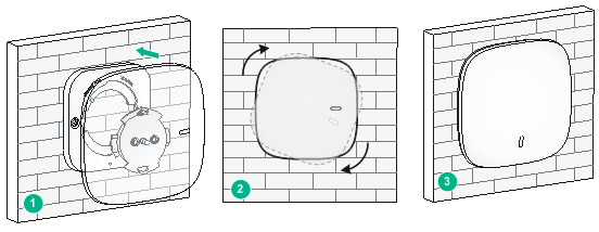
6. Align the two tabs on the AP bracket into the notches on the wall/ceiling bracket, and then rotate the AP clockwise until it snaps into place, as shown in Figure 11.
Figure 11 Attaching the AP to the wall/ceiling bracket
Mounting the AP on a ceiling
|
|
CAUTION: The ceiling for installing the AP must be less than 18 mm (0.71 in) in thickness, and can bear a load of 5 kg (11.02 lb). If the ceiling is not strong enough, use boards to reinforce the ceiling as a best practice. |
To mount the AP on a ceiling:
1. Set the alignment pegs on the AP bracket into the alignment holes in the AP rear. Use the M4 × 7 screw to secure the AP bracket to the AP through the installation hole in the middle of the AP bracket.
2. Mark the installation holes on the ceiling by using the wall/ceiling bracket.
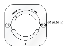
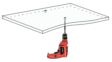
3. Drill two holes with a diameter of 5 mm (0.20 in) in the marked positions, as shown in Figure 12.
Figure 12 Drilling holes in the ceiling
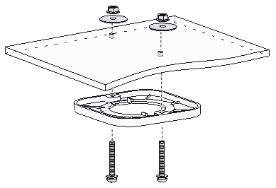
4. Thread the pan-head screws through the installation holes in the wall/ceiling bracket and into holes in the ceiling. Fasten washers and nuts at the other side of the ceiling to attach the wall/ceiling bracket to the ceiling, as shown in Figure 13.
Figure 13 Attaching the wall/ceiling bracket to the ceiling
5. Align the AP with the wall/ceiling bracket and rotate the AP clockwise until it snaps into place, as shown in Figure 14. For more information, see "Mounting the AP on a wall."
Figure 14 Attaching the AP to the wall/ceiling bracket
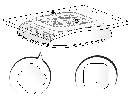
6. Verify that the AP is securely installed to prevent it from falling off.
Connecting IoT access units
|
|
IMPORTANT: · To connect an access unit to the AP, you can use a straight-through or crossover Ethernet cable. To connect two access units, you can only use a straight-through Ethernet cable. · The distances between the first access unit and the AP and between the first and last access units must not exceed 100 m (328.08 ft). · To connect IoT access units, use 802.3at PoE, local power supply, or a power injector to power the AP as a best practice. These powering options support the maximum power consumption of the AP with IoT access units connected to it. |
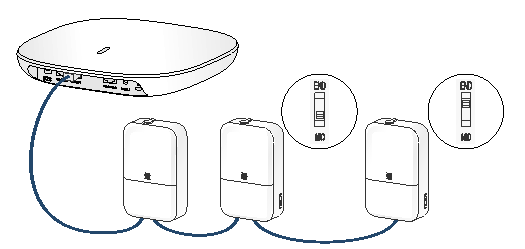
You can connect one or multiple IoT access units to the AP, as shown in Figure 15. The first IoT access unit must be a master IoT access unit (T300M-X or T310M) and other IoT access units must be extender IoT access units (T300-X or T310).
To connect IoT access units:
1. Connect the IoT port on the master IoT access unit to the IoT port of the AP.
2. Connect the OUT port on the IoT access unit to the IN port on another IoT access unit.
3. Use a flat-head screwdriver to push the slide button on each extender IoT access unit except the last one to the MID side, and push the slide button on the last access unit to the END side.
Figure 15 Connecting IoT access units to the AP
Connecting the AP to the power source
You can supply power to the AP by using a local power source, a power injector, or through 802.3af/802.at PoE. To power the AP through PoE, use 802.at PoE as a best practice. When the AP has IoT access units connected to it, 802.3af PoE cannot satisfy the maximum power requirements of the AP.
Check before power-on
Check the following items before powering on the AP:
· To power the AP with local power, make sure the local power supply is reliably grounded.
· To power the AP through PoE, make sure the PoE power supply (PSE) is reliably grounded.
· The AP is to be connected only to PoE networks without routing to the outside plant.
Connecting the PoE power supply
|
|
CAUTION: · Only the GE1 port on the AP supports 802.3af/at PoE. · To avoid port damage, do not use the GE2/IoT port as a PoE port to receive power. · To use both Ethernet ports on the AP, connect an Ethernet cable to one port for PoE connection first, and then connect the other after the AP is powered on. |
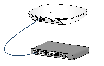
Use an Ethernet cable to connect the Ethernet port on the AP to a port on a switch that supports PoE.
Figure 16 Connecting the PoE power supply
Connecting the local power supply
The power adapter must be ordered separately.
Table 2 Power adapter specifications
|
Item |
Specification |
|
Input |
100 VAC to 240 VAC |
|
Output |
+54 VDC |
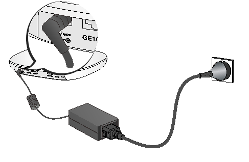
You can power the AP by using an power adapter. Use the power adapter to connect the power port of the AP to the local power source.
Connect the power adapter to the AP as shown in Figure 17 or Figure 18.
Figure 17 Connecting the local power supply (1)
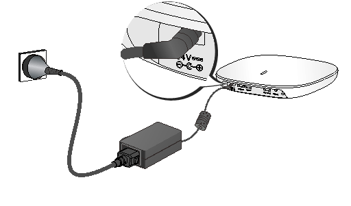
Figure 18 Connecting the local power supply (2)
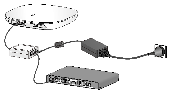
Connecting a power injector
|
|
CAUTION: A power injector must be used together with an LPS-compliant adapter provided by H3C. |
The power injector must be ordered separately.
Connect the power injector to the AP and a switch with Ethernet cable. Use the power adapter to connect the power port of the power injector to the local power source.
Connect the power injector as shown in Figure 19
Figure 19 Power injector power supply
Check after power-on
Verify that the AP is powered on and operating correctly by examining the AP status LED. For more information about AP LEDs, see "Appendix B Ports and LEDs."
Connecting the AP to the network
For Internet or MAN access, connect an Ethernet port on the AP to an Ethernet port on an Ethernet switch, and then verify that the AP has been connected to the network.
All AP settings are configured on the AC when the AP operates as a fit AP. Execute the display wlan ap all command on the AC. If the AP status is R/M, the AP is connected to the network.
<Sysname> display wlan ap all
Total number of APs: 1
Total number of connected APs: 1
Total number of connected manual APs: 1
Total number of connected auto APs: 0
Total number of connected common APs: 1
Total number of connected WTUs: 0
Total number of inside APs: 0
Maximum supported APs: 1024
Remaining APs: 1023
Total AP licenses: 128
Local AP licenses: 128
Server AP licenses: 0
Remaining local AP licenses: 127
Sync AP licenses: 0
AP information
State : I = Idle, J = Join, JA = JoinAck, IL = ImageLoad
C = Config, DC = DataCheck, R = Run M = Master, B = Backup
AP name APID State Model Serial ID
ap1 1 R/M WA5330 219801A20E8182012935
Appendix A Technical specifications
Table 3 Technical specifications
|
Item |
Specification |
|
Dimensions (H × W × D) (without the mounting bracket kit) |
47.5 × 215 × 215 mm (1.87 × 8.46 × 8.46 in) |
|
Weight |
728 g (1.60 lb) |
|
Antenna (built-in) |
· 2.4 G: 6.33 dBi peak gain · 5 G: 6.22 dBi peak gain |
|
· 12.02 W (with no IoT access unit connected to it) · ≤ 24.02 W (with IoT access units connected to it) |
|
|
Powering option |
· Local DC power source · 802.3at PoE · 802.3af PoE · Power injector When the AP has IoT access units connected to it, 802.3af PoE cannot satisfy the maximum power requirements of the AP. Use a local power source, a power injector, or 802.at PoE to power the AP. |
|
Protocol |
IEEE802.11b/g/a/n/ac Wave2 |
Appendix B Ports and LEDs
Ports
The AP provides the following ports:
· One console port
· Two GE ports
· One power port
The AP also has a reset button and a security slot. The security slot is 7 × 3 mm (0.28 × 0.12 in) in size.
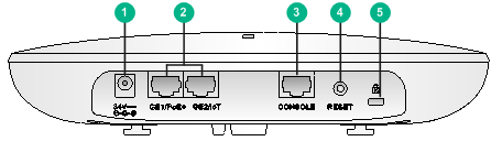
Figure 20 Ports on the AP
|
(1) Power port |
(2) 10/100/1000 Mbps Ethernet ports |
(3) Console port |
|
(4) Reset button |
(5) Security slot |
|
Table 4 Port description
|
Port |
Standards and protocols |
Description |
|
Console port |
RS/EIA-232 |
Used for device configuration and management only. |
|
GE1/PoE+ |
· IEEE802.3 · IEEE802.3u · IEEE802.3af · IEEE802.3at |
Used for connecting the AP to an uplink device for Internet or MAN access. It can also receive PoE+ power from the uplink device It is represented by interface number GE1/0/1 in the MAP file or gigabitethernet 1 in AC configurations. |
|
GE2/IoT |
· IEEE802.3 · IEEE802.3u |
An IoT interface, used for connecting a downlink IoT access unit to the AP. It is represented by interface number GE1/0/2 in the MAP file or gigabitethernet 2 in AC configurations. |
|
Power port (54 VDC) |
N/A |
Used for receiving +54 VDC power from the local power source. |
LEDs
Table 5 LED description
|
LED |
Status |
Description |
||
|
|
Off |
No power is present or the LED was turned off. |
||
|
Yellow |
Steady on |
The AP is initializing, or an initialization exception has occurred. |
||
|
Flashing at 1 Hz |
No radio cards have been detected. |
|||
|
Flashing at 2 Hz |
The Ethernet interfaces are down and no mesh links are established. |
|||
|
Green |
Steady on |
The AP has registered on an AC, but does not have any associated clients. |
||
|
Flashing at 0.5 Hz |
The AP has started up but has not registered on any AC. |
|||
|
Flashing at 1 Hz |
Only the 2.4G radio has associated clients. |
|||
|
Flashing at 2 Hz |
The AP is upgrading the image. |
|||
|
Blue |
Flashing at 1 Hz |
Only the 5G radio has associated clients. |
||
|
Alternating between green and blue at 1 Hz |
Both the 2.4G and 5G radios have associated clients. |
|||
