- Table of Contents
- Related Documents
-
| Title | Size | Download |
|---|---|---|
| 01-Text | 623.83 KB |
Contents
About wireless products deployment and maintenance
Basic principles for WLAN network construction and site survey
Triple-band AP channel setting
Application scenario solutions
Scenario 1: Small coverage area, small number of access clients
Scenario 2: Small coverage area, large number of access clients
Scenario 3: Large coverage area, small number of access clients
Scenario 4: Large coverage area, large number of access clients
Routine maintenance guide for wireless products
About routine maintenance for wireless products
Routine maintenance guidelines
Instructions on fit AP operation and maintenance
Fit AP outdoor and antenna coverage
Daily maintenance instructions
Quarterly maintenance instructions
Annual maintenance instructions
A client fails to obtain an IP address·
A client can obtain an IP address but cannot access the portal authentication page
A client can obtain an IP address and access the portal authentication page but fails authentication
Network failure occurs during Internet access
An AP fails to register to the AC in an AC+fit AP network
Configuring the working channel
About APs' transmit power limit
Specifying a VLAN for WLAN service
About the VLAN for WLAN service
Configuring user isolation in a VLAN··
About user isolation in a VLAN
Configuring static VLAN allocation
Disabling low transmission rates
About disabling low transmission rates
Configuring wireless client rate limit
About wireless client rate limit
Disabling an AP from responding to broadcast probe requests
About broadcast probe request responses
Specifying a VLAN for IRF links
About specifying a VLAN for IRF links
Configuring static link aggregation of switch ports connecting to an IRF fabric
About static link aggregation of switch ports connecting to an IRF fabric
Disabling the spanning tree feature on IRF ports and the peer switch ports
About disabling the spanning tree feature on IRF ports and the peer switch ports
Appendix B Maintenance records·
AC quarterly maintenance record
AC annually maintenance record
AC unexpected issues handling record
System settings modification record·
About wireless products deployment and maintenance
This document mainly contains the following contents:
· The basic principles, regulations, and precautions that you must follow for installing wireless products.
· The instructions for performing daily, quarterly, and annual inspections and maintenance on WLANs and for optimizing the network performance.
Basic principles for WLAN network construction and site survey
Site survey guidelines
Signal strength
To deploy a WLAN, first determine the signal strength requirements in the coverage area.
Table 1 Signal strength requirements
|
Scenario |
Deployment requirements |
|
General AP access |
The signal strength in the target coverage area is not lower than –65 dBm. Deploy the AP or antenna as close as possible to the target area. No metal plates or thick walls obstruct signals. |
|
Use of 500mW APs outdoors |
Pay attention to the RSSIs at the terminal side and the RSSIs detected by the AP side. RSSI greater than 30 is strong, while less than 20 is weak. Make sure both the upstream and downstream signal strengths meet the requirement. |
|
High-density environment, classroom and conference room for example |
As a best practice, install APs in the room. |
|
Environment such as a dormitory, hotel, apartment building |
Use a low-cost deployment scheme, patch APs for example. |
You can use the display wlan client command to view the RSSIs of the clients.
<Sysname> display wlan client verbose
Total number of clients: 64
MAC address : 0cd6-bd00-a98e
IPv4 address : N/A
…
RSSI : 40
Rx/Tx rate : 72.2/72.2
…
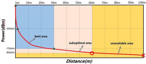
As shown in Figure 1, the signal strength of an AP decreases sharply in the first 10 meters. As the distance increases, the attenuation becomes not obvious.
Figure 1 Signal attenuation diagram
Channel planning
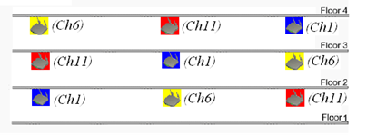
As shown in Figure 2 and Figure 3, configure the APs to operate in non-overlapping channels. For example, you can specify channel 1, channel 6, and channel 11 for adjacent 2.4G APs.
Figure 2 Radio channel planning for APs at the same floor

Figure 3 Radio channel planning for APs at different floors

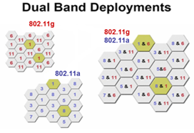
High-density access
WLAN deployment in high-density environment must ensure not only user bandwidth but also signal coverage.
The following methods can be used:
· Using dual-band (or three-band) devices
· Lowering the device installation height
· Realizing physical isolation
· Reducing interference to enhance channel capacity
Figure 4 Dual-band deployment in high-density environment
Channel selection
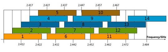
Available channels
Channels 1 to 13 are available in the 2.4G band.
Figure 5 Available channels in the 2.4G band
5.8G available channels are 149, 153, 157, 161, and 165. For 802.11ac devices, the 5.2G channels 36, 40, 44, 48, 52, 56, 60, and 64 are also available. The radar system will conflict with some channels. As a best practice, avoid these channels to prevent wireless terminal access issues.
Bandwidth configuration
|
|
IMPORTANT: An H3C AP has a bandwidth of 80 MHz in the 5G frequency band in 802.11ac radio mode and 40 MHz in 802.11an radio mode. |
As a best practice, use the 20 MHz bandwidth in 802.11n network deployment to strengthen channel isolation and multiplexing and improve the overall performance of the WLAN.
Triple-band AP channel setting
For a triple-band AP, use the available channels in the 2.4G, 5.2G, and 5.8G bands as a best practice. Two 2.4G band channels are not allowed.
Application scenario solutions
General guidelines
· An AP has a coverage radius of 60 m (196.85 ft).
· An AP can provide optimal WLAN access to 15 users concurrently.
· A comprehensive coverage solution is required for a complex deployment environment.
Scenario 1: Small coverage area, small number of access clients
Table 2 Deployment solution for scenario 1
|
Sample scenario |
Characteristics |
Solution |
|
Dormitory |
Limited space. Occurrence of signal leakage can easily interfere with adjacent users. High bandwidth requirement. High proportion of small packet services. Regular Internet access time. Multiple types of terminals. |
Ensure signal coverage and satisfy bandwidth requirements based on the number of users in a single room and signal attenuation through a wall. Indoor APs (patch APs). |
|
Ward |
Low user density. Interference between different signal systems might occur. Bandwidth requirement depends on the services. High requirements on signal strength and coverage rate. Rich terminal types. High roaming demand. |
Ensure optimal signal coverage and satisfy bandwidth requirements based on the number of users in a single room and signal attenuation through a wall. |
Scenario 2: Small coverage area, large number of access clients
Table 3 Deployment solution for scenario 2
|
Sample scenario |
Characteristics |
Solution |
|
Comprehensive office area |
Open and not large area. Dense terminal distribution. High bandwidth requirements. High security requirements for authentication. Terminals different in performance. Sensitive to access experiences. Roaming capacity is required. |
Satisfy bandwidth requirements and improve user access experience. Make full use of partitioning boards and load-bearing walls to reduce same-frequency interference. Optional solution: Install APs on the ceiling. (Do not install the antennas too high.) |
|
Large and medium-sized conference room |
Isolated and completely enclosed space, without partitions and walls. High seat and user density. Concurrent user behaviors. High requirements for access experience. Different terminal performance. |
Choose multi-band high-performance device. Increase available frequency bands. Reduce per-cell coverage area. Reduce co-channel interference. Optional solution: Mount APs on walls, ceiling, and under the seats. |
Scenario 3: Large coverage area, small number of access clients
Table 4 Deployment solution for scenario 3
|
Sample scenario |
Characteristics |
Solution |
|
Hotel guest room |
Relatively isolated and enclosed space. Terminals sparsely distributed. General bandwidth requirements. Large terminal performance difference. Sensitive to signal strengths. |
Offer optimal and extended signal coverage over the target area. Deliver exceptional access experience for different terminals. Optional solution: Install panel APs or high-power APs. |
|
Cottage |
Relatively dispersed users. High bandwidth requirements. Terminals of high bandwidth requirements. Concerned about cost efficiency and network stability and continuity. |
Use terminal equipment with strong adaptability such as CPE to extend AP signals in a wide range. |
Scenario 4: Large coverage area, large number of access clients
Table 5 Deployment solution for scenario 4
|
Sample scenario |
Characteristics |
Solution |
|
Airport |
High user density. Subject to severe interference. Rich terminal types. Sensitive to access experiences. Certain roaming demand. |
Avoid co-channel interference. Ensure signal strengths at crucial areas. Improve WLAN efficiency by channel planning and optimization of parameters. Optional solution: Indoor APs. |
|
Railway station |
Large and open space, without obstacles. Signals from multiple APs can be received. Many hidden nodes. Subject to severe interference and conflict. |
Control signal coverage by using existing obstacles. Decrease the AP power. Decrease the AP installation height. Divide users into groups. Optional solution: Install the APs at a location near the users, under the seats and in the shops for example to increase user experience. |
|
Stadium |
Open space. Signals from multiple APs can be received. High user density. Subject to severe mutual interference. |
Utilize the existing environment and select appropriate antennas to avoid co-channel interference. Deploy the APs under the seats. Optional solution: Outdoor APs + temporary deployment. |
Routine maintenance guide for wireless products
About routine maintenance for wireless products
This chapter provides a guide for routine maintenance and use of H3C wireless products. It mainly describes the matters related to the periodic (daily, weekly, monthly, and annual) inspection of H3C wireless products by the maintenance department.
This chapter is intended for engineers who maintain H3C wireless products.
Maintenance scope
The maintenance mainly involves maintaining the WLAN network elements (including wireless networks and access networks) and monitoring the management and maintenance system (including WLAN network management system and IP integrated network management system).
Maintenance work
The maintenance work includes the following:
· Quarterly inspection—Conduct on-site inspection of all WLAN sites quarterly. Deal with and register the issues found during inspection.
· Fault handling—Identify failures or errors through the network management system and resolve the issues accordingly.
· Complaint handling—Arrive at the site and handle the issues within the specified time after receiving a complaint. Within the specified time after the issue is resolved, pay a return visit to the customer to confirm the fault recovery.
· Network optimization—Optimize the network according to customer complaints, site changes, and the optimization plan.
· WLAN service guarantee—Ensure the stability of the communication devices at the site for large events.
Routine maintenance guidelines
Follow these guidelines to perform routine maintenance:
· Only trained and professional personnel are allowed to perform routine maintenance for wireless devices.
· Keep the equipment room clean, dry, and dust-free. Prevent insects and rats from entering the equipment room.
· Perform routine inspection and test on the equipment every day against this guide and record the inspection results.
· Strictly manage and periodically change the usernames and passwords used for system management, device maintenance, and service operations. Provide the usernames and passwords only to selected personnel.
· Do not install irrelevant software or play games on the device maintenance terminal and Web client. Perform anti-virus scanning on device maintenance terminals and Web clients on a regular basis.
· In case of an alarm for unknown reasons, contact the agent engineer or H3C service engineer immediately.
· Be careful when adjusting cables. Make marks before the adjustment to avoid misconnection.
· Always wear an ESD wrist strip when handling the device hardware.
· Back up configurations and data before resetting the device or changing data.
· Before upgrading the device version, read the upgrade instructions in the release notes carefully and back up relevant configurations.
Instructions on fit AP operation and maintenance
Fit AP indoor coverage
Follow these guidelines to ensure fit AP indoor coverage:
· Determine the installation location and height for the AP and its antenna for optimal signal coverage.
· To avoid management difficulties caused by naming inconsistency, name the AP installation location and the uplink port clearly according to the naming conventions.
· To minimize channel interference and ensure effective management of the AP, specify channels for the AP as required.
· Perform periodical inspections on the AP. Identify whether the LEDs of the AP are normal and whether the working environment including the temperature meets the requirements. Replace and repair the AP beforehand to avoid failure occurrences.
Fit AP outdoor and antenna coverage
Follow these guidelines to ensure fit AP outdoor and antenna coverage:
· If an indoor AP is installed outdoors, make sure the working environment meets the requirements (waterproof, dustproof, and lightning protection) for outdoor installation. You can also install the AP in an outdoor enclosure. The waterproof, lightning protection, and grounding work must be completed as required.
· A fit AP can operate correctly only after it is registered on an AC. Multiple devices and nodes might exist on the link between an outdoor AP and the AC. It is crucial to ensure link quality between the nodes. Therefore, strict inspection must be performed on the link quality.
· When a large number of fit APs register to an AC through DHCP option 43, an AP might get the DHCP address but cannot get the AC address issued by option 43. You can use a PC instead of the AP to catch the packets to identify whether the DHCP server issues the option 43 attribute successfully when issuing the address. If the DHCP server fails to issue the option 43 attribute, identify whether the DHCP server settings are correct. Resolve the issue before serious consequences.
· If the AP has been registered automatically, modify the AP settings timely. Describe the AP including its installation position correctly for easy identification.
Maintenance instructions
Daily maintenance instructions
External environment inspection
Table 6 External environment inspection instructions
|
Maintained item |
Criterion |
|
Power supply monitoring system and the output voltage of the power supply |
Normal output voltage and no power supply exception alarm |
|
Cleanliness in the equipment room |
≤ 3 × 10⁴ particles/m³ (no visible dust on the tabletop over three days) NOTE: Dust diameter ≥ 5 μm |
|
Temperature in the equipment room |
0°C to 45°C (32°F to 113°F) Recommended: 15°C to 25°C (59°F to 77°F) |
|
Relative humidity in the equipment room |
5% RH to 95% RH, non-condensing |
|
Other conditions such as fire or smoke |
No alarm from the fire control system |
Device operating status inspection
Table 7 Device operating status inspection instructions
|
Task |
Commands |
Criterion |
|
View the CPU and memory status on the AC and a proportional number of APs. |
display cpu display memory |
No CPU and memory exceptions have occurred. |
|
View log messages. |
display logbuffer |
No critical and exceptional alarms have been output. |
|
View the LED status. |
See the device installation guide |
N/A |
Service status inspection
Table 8 Service status inspection instructions
|
Task |
Commands |
Criterion |
|
Identify whether the AP can be accessed through Telnet. |
telnet remote-host |
The AP can be accessed through Telnet. |
|
View the AP interface statistics. |
display interface |
The packet transmit and receive statistics are correct. |
|
Identify whether the AP can be pinged successfully. |
ping |
N/A |
|
Identify the signal coverage of the AP. |
display wlan client verbose |
The signal strength is not less than –70 dBm. |
|
Identify the network service port status. |
display tcp display udp |
If you are to not use a network service (FTP), disable the network service port. |
Quarterly maintenance instructions
Hardware maintenance
Table 9 Hardware maintenance instructions
|
Maintained item |
Criterion |
|
Rotation status and sound of the fans on the AC |
Normal rotation and cooling effect. Gentle rotation sound (without motor sound, scratch sound, or hissing sound). |
|
AP LED status |
The LEDs are flashing normally. Support for LEDs depends on the AP model. |
|
Cleanliness of the interior and exterior of the rack |
The surface of the rack is clean, without obvious accumulation of dust. |
|
On-duty phones |
On-duty phones can be dialed in and out smoothly and the phones are operating correctly. |
Software maintenance
Table 10 Software maintenance instructions
|
Maintained item |
Tasks/Commands |
Criterion |
|
System time on the AC and some APs |
display clock |
The system time is correct. If the system time is not correct, change it to the correct time. |
|
Password modification for accessing the AC. |
password |
N/A |
|
Alarm association |
Set conditions to trigger an alarm. Test whether the alarm is triggered and determine the alarm association status. |
The alarm is triggered and association actions are performed. |
|
Network connectivity |
Execute the ping command to test the network connectivity between the maintenance terminal and the hosts. |
The ping operations succeed. |
|
Network device port status |
Log in to the AC from the maintenance terminal through the console port or Telnet. Execute the display interface command in user view to display the interface status. |
No CRC check error. Not operating in half-duplex mode. |
|
AC and AP configuration backup |
Log in to the device from the maintenance terminal through the console port or Telnet. Execute the display current-configuration command in user view to save the configuration. |
N/A |
Annual maintenance instructions
Cable inspection
Table 11 Cable inspection instructions
|
Maintained item |
Criterion |
|
|
Ground resistance |
Using a ground resistance meter to test the ground resistance |
The ground resistance is less than 1 ohm. |
|
Grounding cable connection |
Identify whether the grounding cables are connected reliably. |
All connections are safe, reliable, and not corroded. The grounding cables have not deteriorated. The grounding strips are not corroded and are provided with anti-corrosion protection. |
|
Power cord connection |
Identify whether the power cords are connected securely. |
All connections are safe, reliable, and not corroded. The power cords are in good condition. |
|
Data cable connection |
Identify whether the data cables are connected securely and whether the cables are marked clearly. |
All connections are safe, reliable, and not corroded. The cables are laid tidy and neat. The marks are clear. |
Power supply inspection
Table 12 Power supply inspection instructions
|
Maintained item |
Criterion |
|
UPS |
The output voltage of the UPS is stable. The UPS can supply power stably when the mains electricity fails. |
Troubleshooting
No SSID can be found
User side
To resolve the issue:
1. Verify that the site has WLAN coverage.
2. Verify that the wireless NIC has been enabled in Network Connections.
3. Verify that the wireless button or switch on the client is on.
4. If the issue persists, contact H3C Support.
Device side
To resolve the issue:
1. Check the alarm information on an NMS to verify that the device is reachable.
2. Check the configuration examples on the H3C website for correct AP settings.
3. Verify the following information:
The cables are in good condition.
4. Verify that the AP does not have hardware failures.
A client fails to obtain an IP address
User side
To resolve the issue:
1. Execute the cmd/ipconfig/renew command.
2. Disable and then enable the client NIC or restart the PC.
3. If the issue persists, contact H3C Support.
Device side
To resolve the issue:
1. Check the alarm information on an NMS to verify that the AP is reachable.
2. Verify that all Layer 2 devices allow the service VLAN.
3. Verify that the IP addresses in the DHCP address pool are not used up.
4. Verify that the AP does not have hardware failures.
5. Execute the port access vlan xx command to verify that this failure is not caused by WLAN issues.
6. If the issue persists, contact H3C Support.
A client can obtain an IP address but cannot access the portal authentication page
User side
To resolve the issue:
1. Verify that the client automatically obtains an IP address.
2. Disable the proxy server for the Internet Explorer.
3. Verify that Restricted Sites is not selected.
4. Restore the default settings of the browser or restart the PC.
5. If the issue persists, contact H3C Support.
Device side
To resolve the issue:
1. Ping the portal authentication server to verify that the server does not fail.
2. Disable portal settings, and then enter the IP address of the Web server.
3. If the issue persists, contact H3C Support.
A client can obtain an IP address and access the portal authentication page but fails authentication
User side
To resolve the issue, re-enter the username and password.
Device side
To resolve the issue:
1. Verify that the portal authentication server is operating correctly.
2. Verify that the portal server version is as required.
3. If the issue persists, contact H3C Support.
Slow Internet access
User side
To resolve the issue:
1. Verify that the access location of the user does not change greatly, and the signal strength in the WLAN does not decrease.
2. Verify that no interference devices such as microwave ovens exist, or no any other APs or wireless clients are enabled.
3. If the issue persists, contact H3C Support.
Device side
To resolve the issue:
1. Execute the display wlan ap all radio command to verify that the channel usage of each radio does not exceed 60%.
2. Verify that the upper layer device does not have any bandwidth limitations.
3. Ping the AP or switch to verify that no packet loss exists.
4. Verify that the AP does not have bandwidth limitation settings.
5. Verify that the signal strength does not decrease after the access location is changed.
6. If the issue persists, contact H3C Support.
Network failure occurs during Internet access
User side
To resolve the issue:
1. Verify that the access location of the user does not change greatly, and the signal strength in the WLAN does not decrease.
2. Verify that no interference devices exist, such as microwave ovens or no any other APs or wireless clients are enabled.
3. Verify that the NIC is connected to a correct SSID.
4. If the issue persists, contact H3C Support.
Device side
To resolve the issue:
1. Identify whether the device prompts connection failure. If the device prompts connection failure, perform portal authentication again and then identify whether the network connection is resumed. If yes, check account error or failure records on the portal authentication server.
2. Execute the display wlan client mac-address xxxx-xxxx-xxxx command on the AC to verify that the client has been associated with the AP successfully.
To get the MAC address of the user, obtain the account of the user.
3. Verify that the client does not roam between VLANs.
4. If the issue persists, contact H3C Support.
An AP fails to register to the AC in an AC+fit AP network
User side
To resolve the issue:
1. The AP is not being powered correctly. For example, the PoE switch or the local power source has failed.
2. Verify that no broadcast storm or loop exists by checking the LED on the switch that connects to the AP. If the LED flashes frequently, broadcast storm or loop exists.
3. Verify that the AC and AP versions match.
4. If the issue persists, contact H3C Support.
Device side
To resolve the issue:
1. Verify that the AP can obtain a correct IP address and can be pinged successfully. Verify that the LEDs on the AP flash correctly.
2. Execute the display wlan ap name ap-name verbose command to verify that the AP is operating correctly.
3. Verify that STP is not disabled on the switch connected to the AP.
4. Observe packet statistics changes on the AP and uplink port to verify that no burst traffic exists.
5. Enable CAPWAP debugging to verify that the CAPWAP process has been enabled.
6. Verify that the DHCP server is operating correctly.
7. If the issue persists, contact H3C Support.
WLAN optimization
Configuring the working channel
About working channels
To avoid interference among APs, configure adjacent WLANs to use non-overlapping channels. For example, you can specify channel 1, channel 6, and channel 11 for adjacent 2.4 G WLANs.
As a best practice, deploy APs as shown in Figure 6 and Figure 7 to avoid interference.
Figure 6 Radio channel planning for APs at the same floor

Figure 7 Radio channel planning for APs at different floors
Command reference
Syntax
channel { channel-number | auto { lock | unlock } }
Default
In radio view, a radio uses the configuration in an AP group's radio view.
In an AP group's radio view, the AC automatically selects a channel for a radio and the channel is unlocked.
Views
Radio view
AP group radio view
Parameters
channel-number: Specifies a channel by its number. The value range for this argument varies by country code and radio mode.
auto lock: Configures the AC to automatically select a channel for a radio and lock the channel.
auto unlock: Configures the AC to automatically select a channel for a radio and not lock the channel.
Usage guidelines
When radar signals are detected on the working channel of a radio, one of the following events occurs:
· If the channel is automatically assigned, the radio changes its channel.
· If the channel is manually specified, the radio changes its channel, and switches back to the specified channel after 30 minutes and then starts a quiet timer. If no radar signals are detected within the quiet time, the radio starts to use the channel. If radar signals are detected within the quiet time, the radio changes it channel again.
The configuration in radio view takes precedence over the configuration in an AP group's radio view.
Examples
# Specify working channel 6 for radio 2 of AP ap3.
<AC> system-view
[AC] wlan ap ap3 model WA536-WW
[AC-wlan-ap-ap3] radio 2
[AC-wlan-ap-ap3-radio-1] channel 6
Syntax
channel band-width { 20 | 40 [ auto-switch ] | 80 }
Default
In radio view, a radio uses the configuration in an AP group's radio view.
In an AP group's radio view, the bandwidth mode is 80 MHz for 802.11ac radios, 20 MHz for 802.11gac radios, 40 MHz for 802.11an radios, and 20 MHz for 802.11gn radios.
Views
Radio view
AP group's radio view
Parameters
20: Sets the bandwidth mode to 20 MHz.
40: Sets the bandwidth mode to 40 MHz.
80: Sets the bandwidth mode to 80 MHz.
auto-switch: Allows a radio to switch its bandwidth mode between 20 MHz and 40 MHz. This keyword is applicable only to 802.11gn and 802.11gac radios.
Usage guidelines
This command is applicable only to 802.11n, 802.11ac, and 802.11gac radios. When you change the mode of a radio, the default setting of this command for the new radio mode is restored.
The radio uses the specified 40/80 MHz bandwidth if adjacent channels can be bound to form a 40/80 channel. If adjacent channels cannot form a 40/80 channel, the radio uses the next available bandwidth less than the specified one.
For example, the bandwidth mode is set to 80 MHz. The radio uses the 80 MHz bandwidth if adjacent channels that can be bound together exist. If adjacent channels that can be bound to an 80 MHz channel do not exist, but two adjacent channels that can be bound to a 40 MHz channel exist, the 40 MHz bandwidth is used. If no adjacent channels that can be bound together exist, the radio uses the 20 MHz bandwidth.
The configuration in radio view takes precedence over the configuration in an AP group's radio view.
As a best practice, set the bandwidth mode to 20 MHz for 802.11n radios to improve channel isolation and reuse performance.
Examples
# Set the bandwidth mode to 20 MHz for radio 1 of AP ap3.
<AC> system-view
[AC] wlan ap ap3 model WA536-WW
[AC-wlan-ap-ap3] radio 1
[AC-wlan-ap-ap3-radio-1] channel band-width 20
Limiting APs' transmit power
About APs' transmit power limit
Transmit power reflects the signal strength of a wireless device. A higher transmit power enables a radio to cover a larger area but brings more interference to adjacent devices if they operate in the same channel. You can limit the transmit power of APs to prevent them from interfering with each other.
Command reference
Syntax
max-power radio-power
Default
In radio view, a radio uses the configuration in an AP group's radio view.
In an AP group's radio view, the AP uses the maximum supported transmit power.
Views
Radio view
AP group's radio view
Parameters
radio-power: Specifies the maximum transmit power.
Usage guidelines
The transmit power range supported by a radio varies by country code, channel, AP model, radio mode, antenna type, and bandwidth mode. If you change these attributes for a radio after you set the maximum transmit power, the configured maximum transmit power might be out of the supported transmit power range. If this happens, the system automatically adjusts the maximum transmit power to a valid value.
If you enable power lock, the locked power becomes the maximum transmit power.
The configuration in radio view takes precedence over the configuration in an AP group's radio view.
As a best practice, do not enable auto TPC. If auto TPC is enabled, clients might perform frequent roaming, which affects user experience. For more information about TPC, see the configuration guides of the device.
Examples
# Set the maximum transmit power to 5 dBm for radio 1 of AP ap3.
<AC> system-view
[AC] wlan ap ap3 model WA536-WW
[AC-wlan-ap-ap3] radio 1
[AC-wlan-ap-ap3-radio-1] max-power 5
Specifying a VLAN for WLAN service
About the VLAN for WLAN service
In a WLAN, wireless clients send broadcast and multicast packets at the lowest rate to all the APs in the same VLAN. To avoid broadcast storms and attacks from other WLANs or the wired network, specify different VLANs for a WLAN and its connected wired network.
Restrictions and guidelines
Do not assign ports that connect the AC to APs to the VLAN for WLAN service when local forwarding is enabled.
A WLAN uses one of the following VLANs:
· VLAN specified in service template view.
· VLAN specified when a service template is bound to an AP's radio.
· VLAN authorized by the authentication server for client access.
The priorities of VLANs authorized by the authentication server, specified for a radio, and specified for a service template are in descending order.
For more information, see the configuration guides for the device.
As a best practice, specify a wired device as the VLAN gateway and configure the AC to manage wireless services.
Configuring user isolation in a VLAN
About user isolation in a VLAN
In a WLAN, broadcast and multicast packets from clients are transmitted to all APs in the same VLAN. To prevent broadcast packets from occupying too much channel resources, configure user isolation in the VLAN.
With this feature enabled, clients in a VLAN cannot communicate with each other directly and wired users cannot forward broadcast or multicast packets to wireless users. This greatly reduces traffic and improves performance in the WLAN.
Restrictions and guidelines
To ensure connectivity to the wired network, first add the MAC address of the gateway to the permitted MAC address list by using the user-isolation vlan permit-mac command.
Command reference
Syntax
user-isolation vlan vlan-list enable [ permit-unicast ]
Default
User isolation is disabled for a VLAN.
Views
System view
Parameters
vlan-list: Specifies a space-separated list of up to 10 VLAN items. Each VLAN item specifies a VLAN by VLAN ID or specifies a range of VLANs in the form of vlan-id1 to vlan-id2. The value range for the VLAN IDs is 1 to 4094. If you specify a VLAN range, the value for the vlan-id2 argument must be greater than the value for the vlan-id1 argument.
permit-unicast: Permits unicast packets among users. If you do not specify this keyword, unicast packets are also isolated.
Usage guidelines
To ensure connectivity to the external network, add the MAC address of the gateway to the permitted MAC address list by using the user-isolation vlan permit-mac command.
If you execute the user-isolation vlan enable command multiple times for different VLANs, all the configured user isolation settings take effect. If you execute the user-isolation vlan enable command multiple times for one VLAN, the most recent configuration takes effect.
Examples
# Enable user isolation for VLAN 1.
<Sysname> system-view
[Sysname] user-isolation vlan 1 enable
Syntax
user-isolation vlan vlan-list permit-mac mac-list
Default
No permitted MAC address list is specified for a VLAN.
Views
System view
Parameters
vlan-list: Specifies a space-separated list of up to 10 VLAN items. Each VLAN item specifies a VLAN by VLAN ID or specifies a range of VLANs in the form of vlan-id1 to vlan-id2. The value range for the VLAN IDs is 1 to 4094. If you specify a VLAN range, the value for the vlan-id2 argument must be greater than the value for the vlan-id1 argument.
mac-list: Specifies a space-separated list of up to 16 MAC address items. Each MAC address item specifies a MAC address in the form of H-H-H. The MAC addresses cannot be broadcast or multicast MAC addresses.
Usage guidelines
Packets from users in the permitted MAC address list are not isolated in their corresponding VLANs.
You can execute the user-isolation vlan permit-mac command multiple times to add more MAC addresses to the permitted MAC address list. The number of permitted MAC addresses cannot exceed 16 for a VLAN.
Examples
# Specify permitted MAC addresses 00bb-ccdd-eeff and 0022-3344-5566 for VLAN 1.
<Sysname> system-view
[Sysname] user-isolation vlan 1 permit-mac 00bb-ccdd-eeff 0022-3344-5566
Syntax
undo user-isolation permit-broadcast
Default
The device does not forward broadcast or multicast traffic sent from wired users to wireless users in the VLANs where user isolation is enabled.
Views
System view
Usage guidelines
Isolate broadcast and multicast packets sent from wired users to wireless users only in the following situations:
· The wired and wireless users belong to the same VLAN.
· The AC is an IRF fabric.
Examples
# Disable the AC from forwarding broadcast and multicast packets to wireless clients.
<Sysname> system-view
[AC] undo user-isolation permit-broadcast
Configuring static VLAN allocation
About VLAN allocation methods
When a client comes online for the first time, the associated AP assigns a random VLAN to it. When the client comes online again, the VLAN assigned to the client depends on the allocation method.
· Static allocation—The client inherits the VLAN that has been assigned to it. If the IP address lease has not expired, the client will use the same IP address. This method helps save IP addresses.
· Dynamic allocation—The AP re-assigns a VLAN to the client. This method balances clients in all VLANs. When dynamic allocation is used, it might take a long time for clients re-accessing the same SSID to obtain an IP address.
· Compatible static allocation—The client inherits the VLAN that has been assigned to it when roaming between Comware 5 and Comware 7 ACs.
If you bind a VLAN group to the service template for VLAN allocation, set the VLAN allocation method to static as a best practice.
Command reference
Syntax
client vlan-alloc { dynamic | static | static-compatible }
Default
The VLAN allocation method for clients is dynamic.
Views
Service template view
Parameters
dynamic: Specifies dynamic VLAN allocation.
static: Specifies static VLAN allocation.
static-compatible: Specifies compatible static VLAN allocation.
Examples
# Set the VLAN allocation method for clients to static.
<AC> system-view
[AC] wlan service-template service1
[AC-wlan-st-service1] client vlan-alloc static
Disabling low transmission rates
About disabling low transmission rates
In a WLAN, most broadcast packets and management packets are transmitted at a low rate, 1 Mbps for example. To prevent broadcast and management packets from occupying too much channel resources, you can disable low transmission rates 1, 2, 6, and 9 Mbps.
Restrictions and guidelines
For clients with weak signals, disabling low transmission rates might cause packet loss.
Command reference
Syntax
rate disabled rate-value
Default
In radio view, a radio uses the configuration in an AP group's radio view.
In an AP group's radio view:
· 802.11a/802.11an/802.11ac:
¡ Prohibited rates—None.
¡ Mandatory rates—6, 12, and 24.
¡ Multicast rate—Selected from the mandatory rates.
¡ Supported rates—9, 18, 36, 48, and 54.
· 802.11b:
¡ Prohibited rates—None.
¡ Mandatory rates—1 and 2.
¡ Multicast rate—Selected from the mandatory rates.
¡ Supported rates—5.5 and 11.
· 802.11g/802.11gn/802.11gac:
¡ Prohibited rates—None.
¡ Mandatory rates—1, 2, 5.5, and 11.
¡ Multicast rate—Selected from the mandatory rates.
¡ Supported rates—6, 9, 12, 18, 24, 36, 48, and 54.
Views
Radio view
AP group's radio view
Parameters
rate-value: Specifies the rate value in Mbps. You can set multiple rates and separate them by spaces. The available values for this argument are as follows:
· 802.11a/802.11an/802.11ac—6, 9, 12, 18, 24, 36, 48, and 54.
· 802.11b—1, 2, 5.5, and 11.
· 802.11g/802.11gn/802.11gac—1, 2, 5.5, 6, 9, 11, 12, 18, 24, 36, 48, and 54.
Usage guidelines
The configuration in radio view takes precedence over the configuration in an AP group's radio view.
Examples
# Disable rates 1 Mbps, 2 Mbps, 6 Mpbs, and 9 Mbps for radio 2 of AP test.
<AC> system-view
[AC] wlan ap test
[AC-wlan-ap-test] radio 2
[AC-wlan-ap-test-radio-2] rate disabled 1 2 6 9
# Disable rates 1 Mbps, 2 Mbps, 6 Mbps, and 9 Mbps for radio 2 of APs in AP group test-group.
<AC> system-view
[AC] wlan ap-group test-group
[AC-wlan-ap-group-test-group] ap-model WA536-WW
[AC-wlan-ap-group-test-group-ap-model-WA536-WW] radio 2
[AC-wlan-ap-group-test-group-ap-model-WA536-WW-radio-2] rate disabled 1 2 6 9
Configuring wireless client rate limit
About wireless client rate limit
This feature limits the global rate and per-client rate for uplink client packets to ensure uplink bandwidth usage and per-client bandwidth.
Client rate limit supports the following limit modes:
· Dynamic—Limits the global CIR. The per-client CIR is the global CIR divided by the number of clients. This mode avoids uplink bandwidth waste when there are less clients.
· Static—Limits the per-client CIR.
Command reference
Syntax
client-rate-limit { inbound | outbound } mode { dynamic | static } cir cir
Default
In radio view, a radio uses the configuration in an AP group's radio view.
In an AP group's radio view, radio-based client rate limit is not configured.
Views
Radio view
AP group's radio view
Parameters
inbound: Limits the rate of incoming packets.
outbound: Limit the rate of outgoing packets.
dynamic: Specifies the dynamic rate limit mode. In this mode, the maximum rate for each client is the total maximum rate divided by the number of clients.
static: Specifies the static rate limit mode. The maximum rate for each client is fixed.
cir cir: Specifies the CIR in Kbps. The value range for the cir argument is 16 to 300000. This option sets the maximum rate for each client in static rate limit mode and sets the total maximum rate for all clients in dynamic rate limit mode.
Usage guidelines
For this command to take effect, make sure radio-based client rate limit is enabled.
To limit the rates of both the incoming and outgoing traffic, repeat this command.
The configuration in radio view takes precedence over the configuration in an AP group's radio view.
Examples
# Configure static rate limit in the inbound and outbound directions for radio 1 of AP ap1 to limit the rate to 512 Kbps and 2048 Kbps, respectively.
<AC> system-view
[AC] wlan ap ap1 model WA536-WW
[AC-wlan-ap-ap1] radio 1
[AC-wlan-ap-ap1-1] client-rate-limit enable
[AC-wlan-ap-ap1-1] client-rate-limit inbound mode static cir 512
[AC-wlan-ap-ap1-1] client-rate-limit outbound mode static cir 2048
# Configure static rate limit in the inbound and outbound directions for radio 1 of APs in AP group group1 to limit the rate to 512 Kbps and 2048 Kbps, respectively.
<AC> system-view
[AC] wlan ap-group group1
[AC-wlan-ap-group-group1] ap-model WA536-WW
[AC-wlan-ap-group-group1-ap-model-WA536-WW] radio 1
[AC-wlan-ap-group-group1-ap-model-WA536-WW-radio-1] client-rate-limit enable
[AC-wlan-ap-group-group1-ap-model-WA536-WW-radio-1]client-rate-limit inbound mode static cir 512
[AC-wlan-ap-group-group1-ap-model-WA536-WW-radio-1]client-rate-limit outbound mode static cir 2048
Configuring idle cut
About idle cut
When the AC acts as a portal server, client authentication entries might remain for a long time after the clients go offline. This consumes entry resource and might cause address conflict and authentication failures if the offline clients attempt to come online again.
To solve this issue, enable idle cut for the AC to periodically detect the traffic of each online user. The AC logs out users that do not meet the minimum traffic requirement in the idle timeout period.
Command reference
Syntax
authorization-attribute idle-cut minutes [ flow ]
Default
The idle cut feature is disabled.
Views
ISP domain view
Parameters
minutes: Specifies an idle timeout period in minutes. The value range is 1 to 600.
flow: Specifies the minimum traffic that must be generated in the idle timeout period in bytes. The value range is 1 to 10240000, and the default value is 10240.
Examples
# Set the idle timeout period to 30 minutes for users in ISP domain test, and set the minimum traffic that must be generated in the period to 10240 bytes.
<AC> system-view
[AC] domain test
[AC-isp-test] authorization-attribute idle-cut 30 10240
Disabling an AP from responding to broadcast probe requests
About broadcast probe request responses
In a WLAN, wireless clients can discover APs by broadcasting probe requests that do not carry any SSID. Upon receiving a broadcast probe request, an AP responds with a probe response that carries the AP's service information. To reduce traffic in a WLAN, you can disable APs from responding to broadcast probe requests.
Command reference
Syntax
broadcast-probe reply disable
Default
In AP view, an AP uses the configuration in AP group view.
In AP group view, an AP responds to broadcast probe requests.
Views
AP view
AP group view
Usage guidelines
The configuration in AP view takes precedence over the configuration in AP group view.
Examples
# Disable AP ap1 from responding to broadcast probe requests.
<AC> system-view
[AC] wlan ap ap1 model WA536-WW
[AC-wlan-ap-ap1] broadcast-probe reply disable
# Disable APs in AP group group1 from responding to broadcast probe requests.
<AC> system-view
[AC] wlan ap-group group1
[AC-wlan-ap-group-group1] broadcast-probe reply disable
Configuring WLAN encryption
About WLAN encryption
For security purposes, you can configure WLAN encryption to protect wireless packet transmission.
Restrictions and guidelines
As a best practice for enhanced bandwidth performance, enable the RSN IE and configure CCMP as the cipher suite when you configure WLAN encryption for an 802.11n WLAN.
Command reference
Syntax
akm mode { dot1x | private-psk | psk | anonymous-dot1x }
Default
No AKM mode is set.
Views
WLAN service template view
Parameters
dot1x: Specifies 802.1X as the AKM mode.
private-psk: Specifies private PSK as the AKM mode.
psk: Specifies PSK as the AKM mode.
anonymous-dot1x: Specifies WiFi alliance anonymous 802.1X as the AKM mode.
Usage guidelines
You must set the AKM mode for 802.11i (RSNA) networks.
Each WLAN service template supports only one AKM mode. Set the AKM mode only when the WLAN service template is disabled.
Set the WiFi alliance anonymous 802.1X AKM mode if the OSEN IE is used.
Each of the following AKM modes must be used with a specific authentication mode:
· 802.1X AKM—802.1X authentication mode.
· Private PSK AKM—MAC authentication mode.
· PSK AKM—MAC or bypass authentication mode.
· WiFi alliance anonymous 802.1X AKM—802.1X authentication mode.
For more information about the authentication modes, see the configuration guides for the device.
Examples
# Set the PSK AKM mode.
<Sysname> system-view
[Sysname] wlan service-template security
[Sysname-wlan-st-security] akm mode psk
Syntax
security-ie { osen | rsn | wpa }
Default
OSEN IE, RSN IE, and WPA IE are disabled.
Views
WLAN service template view
Parameters
osen: Enables the OSEN IE in the beacon and probe response frames sent by an AP. The OSEN IE advertises the OSEN capabilities of the AP.
rsn: Enables the RSN IE in the beacon and probe response frames sent by an AP. The RSN IE advertises the RSN capabilities of the AP.
wpa: Enables the WPA IE in the beacon and probe response frames sent by an AP. The WPA IE advertises the WPA capabilities of the AP.
Usage guidelines
You must set the security IE for 802.11i networks. Set a security IE only when the WLAN service template is disabled and the CCMP or TKIP cipher suite is configured.
Set the WiFi alliance anonymous 802.1X AKM mode if the OSEN IE is used.
Examples
# Enable the RSN IE in beacon and probe responses.
<Sysname> system-view
[Sysname] wlan service-template security
[Sysname-wlan-st-security] security-ie rsn
Syntax
cipher-suite { ccmp | tkip | wep40 | wep104 | wep128 }
Default
No cipher suite is specified.
Views
WLAN service template view
Parameters
ccmp: Specifies the AES-CCMP cipher suite.
tkip: Specifies the TKIP cipher suite.
wep40: Specifies the WEP40 cipher suite.
wep104: Specifies the WEP104 cipher suite.
wep128: Specifies the WEP128 cipher suite.
Usage guidelines
You must set the cipher suite for 802.11i networks. Set a cipher suite only when the WLAN service template is disabled.
You must set the TKIP or CCMP cipher suite if you have configured the RSN IE or WPA IE.
The WEP cipher suite includes three types, WEP40, WEP104, and WEP128. Each WLAN service template supports only one type of WEP cipher suite. After you set a type of WEP cipher suite, you must create and apply a key of the same type.
You cannot set WEP128 if you have configured the CCMP or TKIP cipher suite.
Examples
# Set the TKIP cipher suite for frame encryption.
<Sysname> system-view
[Sysname] wlan service-template security
[Sysname-wlan-st-security] cipher-suite tkip
Examining AC-AP link quality
APs are connected to the AC through wired connections based on which AC-AP CAPWAP tunnels are established. To ensure stable transmission, make sure the packet loss rate is lower than 1% and the average delay is smaller than 50 ms for packets with a size of over 1500 bytes.
Specifying a VLAN for IRF links
About specifying a VLAN for IRF links
As a best practice to simplify network management, configure the switch ports that connect to the ACs as follows when multiple ACs connected through Layer 2 switches form an IRF fabric:
· Set the link type of the ports to access.
· Assign the ports to a different VLAN from the service VLAN.
Command reference
Syntax
vlan { vlan-id1 [ to vlan-id2 ] | all }
Default
VLAN 1 (system default VLAN) exists.
Views
System view
Parameters
vlan-id1: Specifies a VLAN ID in the range of 1 to 4094.
vlan-id1 to vlan-id2: Specifies a VLAN range. The vlan-id1 and vlan-id2 arguments specify VLAN IDs. The value range for each of the two arguments is 1 to 4094. The value for the vlan-id2 argument must be equal to or greater than the value for the vlan-id1 argument.
all: Specifies all VLANs except reserved VLANs. The keyword is not supported when the maximum number of VLANs that can be created on a device is less than 4094.
Usage guidelines
You cannot create or delete the system default VLAN (VLAN 1) or reserved VLANs.
Before you delete a dynamic VLAN or a VLAN locked by an application, you must first remove the configuration from the VLAN.
Examples
# Create VLAN 2 and enter its view.
<Sysname> system-view
[Sysname] vlan 2
[Sysname-vlan2]
Syntax
port interface-list
Default
All ports are in VLAN 1.
Views
VLAN view
Parameters
interface-list: Specifies a space-separated list of up to 10 Ethernet interface items. Each item specifies an Ethernet interface or a range of Ethernet interfaces in the form of interface-type interface-number1 to interface-type interface-number2. The value for the interface-number2 argument must be equal to or greater than the value for the interface-number1 argument.
Usage guidelines
This command is applicable only to access ports. By default, all ports are access ports. You can use the port link-type command to configure the port link type.
Examples
# Assign GigabitEthernet 1/0/1 and GigabitEthernet 1/0/2 to VLAN 2.
<Sysname> system-view
[Sysname] vlan 2
[Sysname-vlan2] port gigabitethernet 1/0/1 to gigabitethernet 1/0/2
Configuring static link aggregation of switch ports connecting to an IRF fabric
About static link aggregation of switch ports connecting to an IRF fabric
When multiple ACs connected through Layer 2 switches form an IRF fabric, configure static link aggregation to bind switch ports that connect a switch to a member AC. This simplifies network management.
Command reference
Syntax
interface bridge-aggregation interface-number
Default
No Layer 2 aggregate interfaces exist.
Views
System view
Parameters
interface-number: Specifies a Layer 2 aggregate interface number. The value range for the interface-number argument varies by device model.
Usage guidelines
When you create a Layer 2 aggregate interface, the system automatically creates a Layer 2 aggregation group with the same number. The aggregation group operates in static aggregation mode by default.
Deleting a Layer 2 aggregate interface also deletes the Layer 2 aggregation group. At the same time, the member ports (if any) of the aggregation group leave the aggregation group.
Examples
# Create Layer 2 aggregate interface Bridge-Aggregation 1, and enter its view.
<Sysname> system-view
[Sysname] interface bridge-aggregation 1
[Sysname-Bridge-Aggregation1]
Syntax
port link-aggregation group group-id
Default
An interface does not belong to any aggregation group.
Views
Layer 2 Ethernet interface view
Parameters
group-id: Specifies an aggregation group by its aggregate interface number.
Examples
# Assign Layer 2 Ethernet interface Ten-GigabitEthernet 1/2/0/1 to Layer 2 aggregation group 2.
[Switch] interface Ten-GigabitEthernet 1/2/0/1
[Switch-Ten-GigabitEthernet1/2/0/1] port link-aggregation group 2
Disabling the spanning tree feature on IRF ports and the peer switch ports
About disabling the spanning tree feature on IRF ports and the peer switch ports
When multiple ACs connected through Layer 2 switches form an IRF fabric, disable spanning tree on IRF ports on the AC and the peer ports on the switches.
Command reference
Syntax
undo stp enable
Default
The spanning tree feature is enabled on all ports.
Views
Layer 2 Ethernet interface view
Layer 2 aggregate interface view
Examples
# Disable the spanning tree feature on GigabitEthernet 1/0/1.
<Sysname> system-view
[Sysname] interface gigabitethernet 1/0/1
[Sysname-GigabitEthernet1/0/1] undo stp enable
Appendix A Signal attenuation
WLAN signal propagation model
The received WLAN signal power can be roughly calculated by using the following formula:
Pr [dB] = Pt [dB] + Gt [dB] – PL [dB] + Gr [dB].
Where
· Pr represents the received power.
· Pt represents the maximum transmit power.
· Gt represents the transmitter antenna gain.
· PL represents the path loss.
· Gr represents the receiver antenna gain.
Path loss
The path loss for the 2.4G electromagnetic waves can be calculated by using the following formula:
PathLoss (dB) = 46 + 10*n*LogD (m)
D represents the propagation path and n represents the attenuation coefficient.
For a specific signal coverage area, the signal strength changes reversely reflect the path loss changes.
Attenuation by obstacles
Table 13 Attenuation by obstacles
|
Obstacle |
Signal attenuation (dB) |
Example |
|
Open space |
N/A |
Cafeteria, patio |
|
Wooden object |
3 to 5 |
Wooden interior wall, office partition, door, floor |
|
Plaster object |
5 to 8 |
Plaster interior wall |
|
Object made of synthetic materials |
5 to 8 |
Office partition of synthetic materials |
|
Object made of coal cinders and bricks |
5 to 8 |
Interior wall and exterior wall made of coal cinders and bricks |
|
Asbestos product |
5 to 8 |
Asbestos ceiling tiles |
|
Glass product |
5 to 8 |
Window without color |
|
Human body |
10 to 15 |
A large group of people |
|
Object that contains a large amount of water |
10 to 15 |
Wet wood, glass vat, organism |
|
Object made of bricks |
10 to 15 |
Brick interior wall, exterior wall, ground |
|
Marble object |
15 to 20 |
Marble interior wall, exterior wall, ground |
|
Ceramic object |
20 to 25 |
Ceramic tiles, ceiling, floor |
|
Paper |
20 to 25 |
A large box or pile of paper |
|
Concrete object |
20 to 25 |
|
|
Bullet-proof glass object |
20 to 25 |
Safe tent |
|
Silver-plated object |
25 to 30 |
Mirror |
|
Metal object |
25 to 30 |
Metal office partition, concrete, elevator |
Appendix B Maintenance records
AP installation checklist
|
Project name |
|
Site |
|
Main product |
|
|
Contract No. |
|
Customer contact person |
|
Phone No. |
|
|
Serial No. |
Item |
Requirements |
Installation quality |
Remarks |
|
|
Good |
To be improved |
||||
|
1 |
LED status |
See the AP installation guide. |
|
|
|
|
2 |
Installation environment |
Do not place the AP on a metal surface of any kind. Place the AP in a location with good reception and minimum obstacles exist. |
|
|
|
|
3 |
Do not install the AP near unshielded blasting caps or in an explosive environment. |
|
|
|
|
|
4 |
Lightning protection for outdoor installation |
Install the antenna at a height to provide sufficient signal coverage. Make sure the antenna top is within the 45-degree protection angle of the lightning arrester. |
|
|
|
|
5 |
Install all the lightning arresters outside the outdoor waterproof enclosure. Make sure the lightning arrester for the antenna feed line is reliably grounded. |
|
|
|
|
|
6 |
Make sure the protection angle of the lightning arrester for an antenna is less than 45 degrees in a plain area and less than 30 degrees in a mountain area. The lighting protection system for the AP and the grounding system in the equipment room share the same grounding electrode system. |
|
|
|
|
|
7 |
Make sure the signal lightning arrester is installed securely. The grounding wire of the lightning arrester and the WLAN outdoor enclosure share the same grounding electrode system. |
|
|
|
|
|
8 |
A signal lightning arrester is installed for the uplink port on the switch, and the switch is reliably grounded. |
|
|
|
|
|
9 |
A power lightning arrester is installed for the AC power system in the equipment room. Make sure the grounding cable of the power lightning arrester has a cross-sectional area less than 25 sq cm (1.76 sq in) and a length less than 30 m (98.43 ft). |
|
|
|
|
|
10 |
Outdoor waterproof enclosure installation |
Use cable retainers to secure the cables in the outdoor waterproof enclosure. Do not bend or stretch the RF cables excessively, especially at the connection points. Doing so might break the connection points and increase the signal loss. |
|
|
|
|
11 |
The WLAN outdoor enclosure can be secured to a vertical pole. Make sure the outer diameter of the pole is in the range of 60 mm (2.36 in) to 114 mm (4.49 in). |
|
|
|
|
|
12 |
Secure the enclosure by fastening the screws in the security key hole. |
|
|
|
|
|
13 |
Install and keep the outdoor waterproof enclosure upright. Avoid any angle of inclination. Install the shipped rain baffle for the enclosure. |
|
|
|
|
|
14 |
Indoor AP installation |
See the installation guide for the AP. |
|
|
|
|
15 |
Signal cable installation |
Avoid suspending signal cables in the air. If unavoidable, use cables with double layers of shielding or with metal jacket. Connect the shielding layer or the metal jacket securely to the grounding strip in the equipment room or at the AP installation site. |
|
|
|
|
16 |
AC power cord connection |
Connect the yellow-green wire (ground wire) to PE1, brown wire (live wire) to L1, and blue wire (zero wire) to N1. (The color of wires might be different. Please confirm and distinguish them on site.) |
|
|
|
|
17 |
Do not connect the neutral wire of the power cord to the PE of other communication devices. |
|
|
|
|
|
18 |
Grounding |
Make sure the grounding resistance is less than 5 ohms. For areas where the annual thunderstorm days are less than 20, the grounding resistance can be less than 10 ohms. |
|
|
|
|
19 |
Use a copper grounding cable to minimize the high-frequency impedance. Make sure the grounding cable is as thick and short as possible. Do not use an aluminum grounding cable. |
|
|
|
|
|
20 |
Ensure reliable electrical contact at the connection points of the grounding cable. Provide anticorrosion and rust-proof protection for the connection points. |
|
|
|
|
|
21 |
Do not lay a grounding cable and a signal cable in parallel or entangle them. |
|
|
|
|
|
22 |
Do not add a connector, switch, or fuse to a grounding cable. |
|
|
|
|
|
23 |
Use a green and yellow plastic insulated copper grounding cable. |
|
|
|
|
|
24 |
Make sure the grounding cable is as short as possible and the length of the grounding cable does not exceed 30 m (98.43 ft). If the distance exceeds 30 m (98.43 ft), add a grounding strip or rearrange the grounding strips to reduce the distance. Do not loop the grounding cable. |
|
|
|
|
|
25 |
Total number of unqualified items |
|
|
|
|
|
26 |
Date to complete the rectification |
|
|
|
|
Inspector: Customer:
Date:
AC daily maintenance record
Date:
|
Duty hour: |
Handed over by |
Taken over by |
||
|
Maintenance category |
Item |
Maintenance status |
Remarks |
Maintained by |
|
Operating environment |
Power supply (DC/AC) |
q Normal q Abnormal |
|
|
|
Temperature (normal: 0°C/32°F to 35°C/95°F) |
q Normal q Abnormal |
|
|
|
|
Humidity (normal: 20% to 80%) |
q Normal q Abnormal |
|
|
|
|
Cleanliness of the equipment room (dust content) |
q Good q Poor |
|
|
|
|
Other conditions (fire alarms, smoke) |
q Normal q Abnormal |
|
|
|
|
Operating status |
System operating status |
q Normal q Abnormal |
|
|
|
Alarm information |
q Normal q Abnormal |
|
|
|
|
LED status |
q Normal q Abnormal |
|
|
|
|
CPU and memory status |
q Normal q Abnormal |
|
|
|
|
Log information |
q Normal q Abnormal |
|
|
|
|
Sample inspection |
Whether the AP can be accessed through Telnet |
q Normal q Abnormal |
|
|
|
AP port statistics |
q Normal q Abnormal |
|
|
|
|
Whether the AP can be pinged |
q Normal q Abnormal |
|
|
|
|
AP signal coverage |
q Normal q Abnormal |
|
|
|
|
AP network service port status |
q Normal q Abnormal |
|
|
|
|
Failure and troubleshooting |
|
|||
|
Issues to resolve |
|
|||
|
Monitor inspection |
|
|||
AC quarterly maintenance record
Maintenance period:
|
Maintenance category |
Item |
Maintenance status |
Remarks |
Maintained by |
|
Device maintenance |
Fan status of the AC |
q Normal q Abnormal |
|
|
|
AP LED status |
q Normal q Abnormal |
|
|
|
|
Quarterly maintenance |
System time of the AC and AP |
q Normal q Abnormal |
|
|
|
Change of the password for accessing the AC |
q Completed q Uncompleted |
|
|
|
|
Alarm association effectiveness |
q Normal q Abnormal |
|
|
|
|
Network connectivity |
q Normal q Abnormal |
|
|
|
|
Networking device port status |
q Normal q Abnormal |
|
|
|
|
Backup of AC and AP configurations |
q Completed q Uncompleted |
|
|
|
|
Rack cleanliness |
q Normal q Abnormal |
|
|
|
|
Duty phone status |
q Normal q Abnormal |
|
|
|
|
Issue handling |
|
|||
|
Issues to be resolved |
|
|||
|
Monitor inspection |
|
|||
AC annually maintenance record
Maintenance period:
|
Category |
Item |
Maintenance status |
Remarks |
Maintained by |
|
Cable connection |
Grounding resistance |
q Normal q Abnormal |
|
|
|
Grounding cable connection |
q Normal q Abnormal |
|
|
|
|
Power cord connection |
q Normal q Abnormal |
|
|
|
|
Data cable connection and wiring |
q Normal q Abnormal |
|
|
|
|
Power supply |
UPS |
q Normal q Abnormal |
|
|
|
Issue handling |
|
|||
|
Issues to resolve |
|
|||
|
Monitor inspection |
|
|||
AC unexpected issues handling record
|
Time of occurrence: |
Time of resolution: |
||
|
Personnel on duty |
|
Handled by |
|
|
Issue (including hardware and software) category: AP issues AC issues Client issues Grid power supply/UPS issues Grounding or power connection issues Product installation issues Operation issues Other issues (temperature, humidity, damage by rats, and electromagnetic interference) Force majeure (floods, hurricanes, and earthquakes) Other products Product: Manufacturer: Product: Manufacturer: Product: Manufacturer: |
|||
|
Issue description:
|
|||
|
Handling methods and results:
|
|||
Hardware replacement record
|
Reason for replacement |
Name/model/barcode of the original product |
Name/model/barcode of the new product |
Quantity |
Date |
Replaced by |
|
|
|
|
|
|
|
|
|
|
|
|
|
|
|
|
|
|
|
|
|
|
|
|
|
|
|
|
|
|
|
|
|
|
|
|
|
|
|
|
|
|
|
|
|
|
|
|
|
|
|
|
|
|
|
|
|
|
|
|
|
|
|
System settings modification record
|
Modified by |
Modification time |
Reason for modification |
Modified content |
|
|
|
|
|
|
|
|
|
|
|
|
|
|
|
|
|
|
|
|
|
|
|
|
|