- Table of Contents
- Related Documents
-
| Title | Size | Download |
|---|---|---|
| 05-H3C_IS-IS_Route_Summarization_Configuration_Examples | 63.77 KB |
H3C IS-IS Route Summarization Configuration Examples
Software version: Release 7577P04
Document version: 6W100-20190330
Copyright © 2019 New H3C Technologies Co., Ltd. All rights reserved.
No part of this manual may be reproduced or transmitted in any form or by any means without prior written consent of New H3C Technologies Co., Ltd.
Except for the trademarks of New H3C Technologies Co., Ltd., any trademarks that may be mentioned in this document are the property of their respective owners.
The information in this document is subject to change without notice.
Contents
Example: Configuring IS-IS route summarization
Configuring IP addresses for interfaces
Configuring IS-IS route summarization
Introduction
This document provides IS-IS route summarization configuration examples.
Prerequisites
The configuration examples in this document were created and verified in a lab environment, and all the devices were started with the factory default configuration. When you are working on a live network, make sure you understand the potential impact of every command on your network.
This document assumes that you have basic knowledge of IS-IS route summarization.
Example: Configuring IS-IS route summarization
Network configuration
As shown in Figure 1, the five departments of a company use IS-IS to connect to the backbone network. The three departments are assigned the networks 192.168.1.0/24, 192.168.2.0/24, 192.168.3.0/24,. Configure IS-IS route summarization to reduce routing entries and save system resources for Device B.
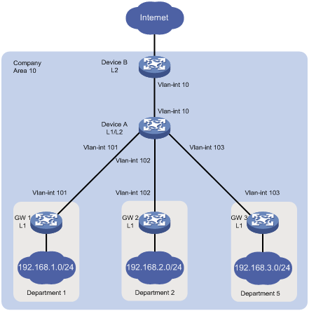
Analysis
Configure route summarization on Device A because route summarization applies only to locally generated LSPs.
To avoid blackhole routes, set the summary route to 192.168.0.0/22.
Procedures
Configuring IP addresses for interfaces
# Configure an IP address for the interface VLAN-interface 10 on Device A.
<DeviceA> system-view
[DeviceA] interface vlan-interface 10
[DeviceA-Vlan-interface10] ip address 172.16.1.1 24
[DeviceA-Vlan-interface10] quit
# Configure IP addresses for other interfaces as shown in Figure 1 in the same way VLAN-interface 10 is configured. (Details not shown.)
Configuring basic IS-IS
Configuring Device A
# Enable IS-IS on Device A and configure Device A as a Level-1-2 router.
[DeviceA] isis 1
[DeviceA-isis-1] network-entity 10.0000.0000.0001.00
[DeviceA-isis-1] is-level level-1-2
[DeviceA-isis-1] quit
# Enable IS-IS on the interface VLAN-interface 10.
[DeviceA] interface vlan-interface 10
[DeviceA–Vlan-interface10] isis enable 1
[DeviceA–Vlan-interface10] quit
# Configure other interfaces in the same way VLAN-interface 10 is configured. (Details not shown.)
Configuring Device B
# Enable IS-IS on Device B and configure Device B as a Level-2 router.
[DeviceB] isis 1
[DeviceB-isis-1] network-entity 10.0000.0000.0002.00
[DeviceB-isis-1] is-level level-2
[DeviceB-isis-1] quit
# Enable IS-IS on the interface VLAN-interface 10.
[DeviceB] interface vlan-interface 10
[DeviceB–Vlan-interface10] isis enable 1
[DeviceB–Vlan-interface10] quit
Configuring the gateways
# Enable IS-IS on GW 1 and configure GW 1 as a Level-1 router.
[GW1] isis 1
[GW1-isis-1] network-entity 10.0001.0001.0001.00
[GW1-isis-1] is-level level-1
[GW1-isis-1] quit
# Enable IS-IS on the interface VLAN-interface 11.
[GW1] interface vlan-interface 11
[GW1–Vlan-interface11] isis enable 1
[GW1–Vlan-interface11] quit
# Configure other gateways in the same way GW 1 is configured. (Details not shown.)
Displaying IS-IS routing information on Device B
# Display IS-IS routing information on Device B to view the network address of each department.
[DeviceB] display isis route
Route information for IS-IS(1)
------------------------------
Level-2 IPv4 Forwarding Table
-----------------------------
IPv4 Destination IntCost ExtCost ExitInterface NextHop Flags
-------------------------------------------------------------------------------
192.168.1.0/24 30 NULL Vlan10 172.16.1.1 R/-/-
10.1.1.0/24 20 NULL Vlan10 172.16.1.1 R/-/-
192.168.2.0/24 30 NULL Vlan10 172.16.1.1 R/-/-
10.1.2.0/24 20 NULL Vlan10 172.16.1.1 R/-/-
192.168.3.0/24 30 NULL Vlan10 172.16.1.1 R/-/-
10.1.3.0/24 20 NULL Vlan10 172.16.1.1 R/-/-
172.16.1.0/24 10 NULL Vlan10 Direct D/L/-
Flags: D-Direct, R-Added to Rib, L-Advertised in LSPs, U-Up/Down bit set
Configuring IS-IS route summarization
# Configure IS-IS route summarization on Device A.
[DeviceA] isis 1
[DeviceA-isis-1]address-family ipv4
[DeviceA-isis-1-ipv4]summary 192.168.0.0 22
Verifying the configuration
# Display IS-IS routing information on Device B.
[DeviceB] display isis route
Route information for IS-IS(1)
------------------------------
Level-2 IPv4 Forwarding Table
-----------------------------
IPv4 Destination IntCost ExtCost ExitInterface NextHop Flags
-------------------------------------------------------------------------------
10.1.1.0/24 20 NULL Vlan10 172.16.1.1 R/-/-
10.1.2.0/24 20 NULL Vlan10 172.16.1.1 R/-/-
10.1.3.0/24 20 NULL Vlan10 172.16.1.1 R/-/-
172.16.1.0/24 10 NULL Vlan10 Direct D/L/-
192.168.0.0/22 30 NULL Vlan10 172.16.1.1 R/-/-
Flags: D-Direct, R-Added to Rib, L-Advertised in LSPs, U-Up/Down bit set
The output shows that the networks have been summarized into a single network 192.168.0.0/22.
Configuration files
· Device A:
#
isis 1
network-entity 10.0000.0000.0001.00
#
address-family ipv4 unicast
summary 192.168.0.0 255.255.252.0
#
vlan 10
#
vlan 101 to 103
#
interface vlan-interface10
ip address 172.16.1.1 255.255.255.0
isis enable 1
#
interface vlan-interface101
ip address 10.1.1.1 255.255.255.0
isis enable 1
#
interface vlan-interface102
ip address 10.1.2.1 255.255.255.0
isis enable 1
#
interface vlan-interface103
ip address 10.1.3.1 255.255.255.0
isis enable 1
#
· Device B:
#
isis 1
is-level level-2
network-entity 10.0000.0000.0002.00
#
vlan 10
#
interface vlan-interface10
ip address 172.16.1.2 255.255.255.0
isis enable 1
#
· GW 1:
#
isis 1
is-level level-1
network-entity 10.0001.0001.0001.00
#
vlan 11
#
vlan 101
#
interface vlan-interface101
ip address 10.1.1.2 255.255.255.0
isis enable 1
#
interface vlan-interface11
ip address 192.168.1.1 255.255.255.0
isis enable 1
#
· The configuration files for other gateways are similar to the configuration file for GW 1. (Details not shown.)
Related documentation
· H3C S7500E Switch Series Layer 3—IP Routing Command Reference-R757X
· H3C S7500E Switch Series Layer 3—IP Routing Configuration Guide-R757X