- Related Documents
-
| Title | Size | Download |
|---|---|---|
| 01-H3C_BGP_Configuration_Examples | 102.32 KB |
H3C BGP Configuration Examples
Software version: Release 7577P04
Document version: 6W100-20190330
Copyright © 2019 New H3C Technologies Co., Ltd. All rights reserved.
No part of this manual may be reproduced or transmitted in any form or by any means without prior written consent of New H3C Technologies Co., Ltd.
Except for the trademarks of New H3C Technologies Co., Ltd., any trademarks that may be mentioned in this document are the property of their respective owners.
The information in this document is subject to change without notice.
Introduction
This document provides BGP configuration examples.
Prerequisites
The configuration examples in this document were created and verified in a lab environment, and all the devices were started with the factory default configuration. When you are working on a live network, make sure you understand the potential impact of every command on your network.
This document assumes that you have basic knowledge of BGP.
Example: Configuring basic BGP
Network configuration
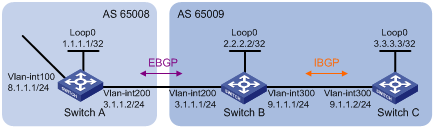
As shown in Figure 1, all switches run BGP. Run EBGP between Switch A and Switch B, and run IBGP between Switch B and Switch C so that Switch C can access the network 8.1.1.0/24 connected to Switch A.
Analysis
To enable Switch B to communicate with Switch C through loopback interfaces, enable OSPF in AS 65009.
By default, BGP does not advertise local networks. To enable Switch C to access the network 8.1.1.0/24 connected directly to Switch A, perform the following tasks:
· Add network 8.1.1.0/24 to the BGP routing table of Switch A.
· Add networks 3.1.1.0/24 and 9.1.1.0/24 to the BGP routing table of Switch B.
Restrictions and guidelines
When you configure basic BGP, follow these restrictions and guidelines:
· Use loopback interfaces to establish IBGP connections to prevent route flapping caused by port state changes.
· Loopback interfaces are virtual interfaces. Use the peer connect-interface command to specify the loopback interface as the source interface for establishing BGP connections.
· The EBGP peers, Switch A and Switch B, are located in different ASs. Typically, their loopback interfaces are not reachable to each other, so the switches use directly connected interfaces to establish EBGP sessions.
Procedures
1. Configure IP addresses for interfaces:
# Configure an IP address for VLAN-interface 100.
<SwitchA> system-view
[SwitchA] interface Vlan-interface 100
[SwitchA-Vlan-interface100] ip address 8.1.1.1 24
# Configure IP addresses for other interfaces in the same way that VLAN-interface 100 is configured. (Details not shown.)
2. Configure IBGP:
# Configure Switch B.
<SwitchB> system-view
[SwitchB] bgp 65009
[SwitchB-bgp-default] router-id 2.2.2.2
[SwitchB-bgp-default] peer 3.3.3.3 as-number 65009
[SwitchB-bgp-default] peer 3.3.3.3 connect-interface Loopback 0
[SwitchB-bgp-default] address-family ipv4 unicast
[SwitchB-bgp-default-ipv4] peer 3.3.3.3 enable
[SwitchB-bgp-default-ipv4] quit
[SwitchB-bgp-default] quit
[SwitchB] ospf 1
[SwitchB-ospf-1] area 0
[SwitchB-ospf-1-area-0.0.0.0] network 2.2.2.2 0.0.0.0
[SwitchB-ospf-1-area-0.0.0.0] network 9.1.1.0 0.0.0.255
[SwitchB-ospf-1-area-0.0.0.0] quit
[SwitchB-ospf-1] quit
# Configure Switch C.
<SwitchC> system-view
[SwitchC] bgp 65009
[SwitchC-bgp-default] router-id 3.3.3.3
[SwitchC-bgp-default] peer 2.2.2.2 as-number 65009
[SwitchC-bgp-default] peer 2.2.2.2 connect-interface Loopback 0
[SwitchC-bgp-default] address-family ipv4 unicast
[SwitchC-bgp-default-ipv4] peer 2.2.2.2 enable
[SwitchC-bgp-default-ipv4] quit
[SwitchC-bgp-default] quit
[SwitchC] ospf 1
[SwitchC-ospf-1] area 0
[SwitchC-ospf-1-area-0.0.0.0] network 3.3.3.3 0.0.0.0
[SwitchC-ospf-1-area-0.0.0.0] network 9.1.1.0 0.0.0.255
[SwitchC-ospf-1-area-0.0.0.0] quit
[SwitchC-ospf-1] quit
# Display BGP peer information on Switch C.
[SwitchC] display bgp peer ipv4
BGP local router ID : 3.3.3.3
Local AS number : 65009
Total number of peers : 1 Peers in established state : 1
Peer AS MsgRcvd MsgSent OutQ PrefRcv Up/Down State
2.2.2.2 65009 2 2 0 0 00:00:13 Established
The output shows that Switch C has established an IBGP peer relationship with Switch B.
3. Configure EBGP:
# Configure Switch A.
<SwitchA> system-view
[SwitchA] bgp 65008
[SwitchA-bgp-default] router-id 1.1.1.1
[SwitchA-bgp-default] peer 3.1.1.1 as-number 65009
[SwitchA-bgp-default] address-family ipv4 unicast
[SwitchA-bgp-default-ipv4] peer 3.1.1.1 enable
[SwitchA-bgp-default-ipv4] network 8.1.1.0 24
[SwitchA-bgp-default-ipv4] quit
[SwitchA-bgp-default] quit
# Configure Switch B.
[SwitchB] bgp 65009
[SwitchB-bgp-default] peer 3.1.1.2 as-number 65008
[SwitchB-bgp-default] address-family ipv4 unicast
[SwitchB-bgp-default-ipv4] peer 3.1.1.2 enable
[SwitchB-bgp-default-ipv4] quit
[SwitchB-bgp-default] quit
# Display BGP peer information on Switch B.
[SwitchB] display bgp peer ipv4
BGP local router ID : 2.2.2.2
Local AS number : 65009
Total number of peers : 2 Peers in established state : 2
Peer AS MsgRcvd MsgSent OutQ PrefRcv Up/Down State
3.3.3.3 65009 4 4 0 0 00:02:49 Established
3.1.1.2 65008 2 2 0 0 00:00:05 Established
The output shows that Switch B has established an IBGP peer relationship with Switch C and an EBGP peer relationship with Switch A.
# Display the BGP routing table on Switch A.
[SwitchA] display bgp routing-table ipv4
Total number of routes: 1
BGP local router ID is 1.1.1.1
Status codes: * - valid, > - best, d - dampened, h - history,
s - suppressed, S - stale, i - internal, e - external
Origin: i - IGP, e - EGP, ? - incomplete
Network NextHop MED LocPrf PrefVal Path/Ogn
* > 8.1.1.0/24 8.1.1.1 0 32768 i
# Display the BGP routing table on Switch B.
[SwitchB] display bgp routing-table ipv4
Total number of routes: 1
BGP local router ID is 2.2.2.2
Status codes: * - valid, > - best, d - dampened, h - history,
s - suppressed, S - stale, i - internal, e - external
Origin: i - IGP, e - EGP, ? - incomplete
Network NextHop MED LocPrf PrefVal Path/Ogn
* >e 8.1.1.0/24 3.1.1.2 0 0 65008i
# Display the BGP routing table on Switch C.
[SwitchC] display bgp routing-table ipv4
Total number of routes: 1
BGP local router ID is 3.3.3.3
Status codes: * - valid, > - best, d - dampened, h - history,
s - suppressed, S - stale, i - internal, e - external
Origin: i - IGP, e - EGP, ? - incomplete
Network NextHop MED LocPrf PrefVal Path/Ogn
i 8.1.1.0/24 3.1.1.2 0 100 0 65008i
The outputs show that Switch A has learned no route to AS 65009, and Switch C has learned network 8.1.1.0, but the next hop 3.1.1.2 is unreachable. As a result, the route is invalid.
4. Configure BGP to redistribute direct routes on Switch B:
# Configure Switch B.
[SwitchB] bgp 65009
[SwitchB-bgp-default] address-family ipv4 unicast
[SwitchB-bgp-default-ipv4] network 3.1.1.0 24
[SwitchB-bgp-default-ipv4] network 9.1.1.0 24
[SwitchB-bgp-default-ipv4] quit
[SwitchB-bgp-default] quit
# Display the BGP routing table on Switch A.
[SwitchA] display bgp routing-table ipv4
Total number of routes: 3
BGP local router ID is 1.1.1.1
Status codes: * - valid, > - best, d - dampened, h - history,
s - suppressed, S - stale, i - internal, e - external
Origin: i - IGP, e - EGP, ? - incomplete
Network NextHop MED LocPrf PrefVal Path/Ogn
* >e 3.1.1.0/24 3.1.1.1 0 0 65009?
* > 8.1.1.0/24 8.1.1.1 0 32768 i
* >e 9.1.1.0/24 3.1.1.1 0 0 65009i
The output shows that route 9.1.1.0/24 has been added in Switch A's routing table.
# Display the BGP routing table on Switch C.
[SwitchC] display bgp routing-table ipv4
Total number of routes: 3
BGP local router ID is 3.3.3.3
Status codes: * - valid, > - best, d - dampened, h - history,
s - suppressed, S - stale, i - internal, e - external
Origin: i - IGP, e - EGP, ? - incomplete
Network NextHop MED LocPrf PrefVal Path/Ogn
* >i 3.1.1.0/24 2.2.2.2 0 100 0 ?
* >i 8.1.1.0/24 3.1.1.2 0 100 0 65008i
* >i 9.1.1.0/24 2.2.2.2 0 100 0 i
The output shows that the route 8.1.1.0 becomes valid with the next hop as Switch A.
Verifying the configuration
# Verify that Switch C can ping 8.1.1.1.
[SwitchC] ping 8.1.1.1
Ping 8.1.1.1 (8.1.1.1): 56 data bytes, press CTRL_C to break
56 bytes from 8.1.1.1: icmp_seq=0 ttl=254 time=10.000 ms
56 bytes from 8.1.1.1: icmp_seq=1 ttl=254 time=4.000 ms
56 bytes from 8.1.1.1: icmp_seq=2 ttl=254 time=4.000 ms
56 bytes from 8.1.1.1: icmp_seq=3 ttl=254 time=3.000 ms
56 bytes from 8.1.1.1: icmp_seq=4 ttl=254 time=3.000 ms
--- Ping statistics for 8.1.1.1 ---
5 packet(s) transmitted, 5 packet(s) received, 0.0% packet loss
round-trip min/avg/max/std-dev = 3.000/4.800/10.000/2.638 ms
Configuration files
· Switch A:
#
vlan 100
#
vlan 200
#
interface Loopback0
ip address 1.1.1.1 255.255.255.255
#
interface Vlan-interface100
ip address 8.1.1.1 255.255.255.0
#
interface Vlan-interface200
ip address 3.1.1.2 255.255.255.0
#
bgp 65008
router-id 1.1.1.1
peer 3.1.1.1 as-number 65009
#
address-family ipv4 unicast
network 8.1.1.0 255.255.255.0
peer 3.1.1.1 enable
#
· Switch B:
#
vlan 200
#
vlan 300
#
interface Loopback0
ip address 2.2.2.2 255.255.255.255
#
interface Vlan-interface200
ip address 3.1.1.1 255.255.255.0
#
interface Vlan-interface300
ip address 9.1.1.1 255.255.255.0
#
bgp 65009
router-id 2.2.2.2
peer 3.1.1.2 as-number 65008
peer 3.3.3.3 as-number 65009
peer 3.3.3.3 connect-interface Loopback0
#
address-family ipv4 unicast
network 3.1.1.0 255.255.255.0
network 9.1.1.0 255.255.255.0
peer 3.1.1.2 enable
peer 3.3.3.3 enable
#
ospf 1
area 0.0.0.0
network 2.2.2.2 0.0.0.0
network 9.1.1.0 0.0.0.255
#
· Switch C:
#
vlan 300
#
interface Loopback0
ip address 3.3.3.3 255.255.255.255
#
interface Vlan-interface300
ip address 9.1.1.2 255.255.255.0
#
bgp 65009
router-id 3.3.3.3
peer 2.2.2.2 as-number 65009
peer 2.2.2.2 connect-interface Loopback0
#
address-family ipv4 unicast
peer 2.2.2.2 enable
#
ospf 1
area 0.0.0.0
network 3.3.3.3 0.0.0.0
network 9.1.1.0 0.0.0.255
#
Examples: Configuring BGP and IGP route redistribution
Network configuration
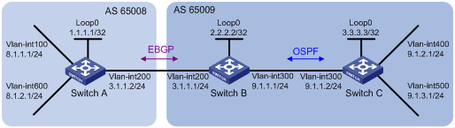
As shown in Figure 2, all devices of company A belong to AS 65008 and all devices of company B belong to AS 65009. Run EBGP between Switch A and Switch B, and run OSPF between Switch B and Switch C to allow communication only between networks 9.1.2.0/24 and 8.1.1.0/24.
Analysis
To enable Switch A to obtain the route to 9.1.2.0/24, configure BGP to redistribute routes from OSPF on Switch B. To enable Switch C to obtain the route to 8.1.1.0/24, configure OSPF to redistribute routes from BGP on Switch B.
Restrictions and guidelines
The EBGP peers, Switch A and Switch B, are located in different ASs. Typically, their loopback interfaces are not reachable to each other, so the switches use directly connected interfaces to establish EBGP sessions.
Procedures
1. Configure IP addresses for interfaces:
# Configure an IP address for VLAN-interface 100.
<SwitchA> system-view
[SwitchA] interface Vlan-interface 100
[SwitchA-Vlan-interface100] ip address 8.1.1.1 24
# Configure IP addresses for other interfaces in the same way that VLAN-interface 100 is configured. (Details not shown.)
2. Enable OSPF in AS 65009:
# Configure Switch B.
<SwitchB> system-view
[SwitchB] ospf 1
[SwitchB-ospf-1] area 0
[SwitchB-ospf-1-area-0.0.0.0] network 2.2.2.2 0.0.0.0
[SwitchB-ospf-1-area-0.0.0.0] network 9.1.1.0 0.0.0.255
[SwitchB-ospf-1-area-0.0.0.0] quit
[SwitchB-ospf-1] quit
# Configure Switch C.
<SwitchC> system-view
[SwitchC] ospf 1
[SwitchC-ospf-1] area 0
[SwitchC-ospf-1-area-0.0.0.0] network 9.1.1.0 0.0.0.255
[SwitchC-ospf-1-area-0.0.0.0] network 9.1.2.0 0.0.0.255
[SwitchC-ospf-1-area-0.0.0.0] quit
[SwitchC-ospf-1] quit
3. Configure the EBGP connection and add network 8.1.1.0/24 to the BGP routing table of Switch A:
# Configure Switch A.
<SwitchA> system-view
[SwitchA] bgp 65008
[SwitchA-bgp-default] router-id 1.1.1.1
[SwitchA-bgp-default] peer 3.1.1.1 as-number 65009
[SwitchA-bgp-default] address-family ipv4 unicast
[SwitchA-bgp-default-ipv4] peer 3.1.1.1 enable
[SwitchA-bgp-default-ipv4] network 8.1.1.0 24
[SwitchA-bgp-default-ipv4] quit
[SwitchA-bgp-default] quit
# Configure Switch B.
[SwitchB] bgp 65009
[SwitchB-bgp-default] router-id 2.2.2.2
[SwitchB-bgp-default] peer 3.1.1.2 as-number 65008
[SwitchB-bgp-default] address-family ipv4 unicast
[SwitchB-bgp-default-ipv4] peer 3.1.1.2 enable
4. Configure BGP and IGP route redistribution:
# Configure route redistribution between BGP and OSPF on Switch B.
[SwitchB-bgp-default-ipv4] import-route ospf 1
[SwitchB-bgp-default-ipv4] quit
[SwitchB-bgp-default] quit
[SwitchB] ospf 1
[SwitchB-ospf-1] import-route bgp
[SwitchB-ospf-1] quit
# Display the BGP routing table on Switch A.
[SwitchA] display bgp routing-table ipv4
Total number of routes: 3
BGP local router ID is 1.1.1.1
Status codes: * - valid, > - best, d - dampened, h - history,
s - suppressed, S - stale, i - internal, e - external
Origin: i - IGP, e - EGP, ? - incomplete
Network NextHop MED LocPrf PrefVal Path/Ogn
* > 8.1.1.0/24 8.1.1.1 0 32768 i
* >e 9.1.2.0/24 3.1.1.1 1 0 65009?
The output shows that Switch A has obtained the route to 9.1.2.0/24.
# Display the OSPF routing table on Switch C.
[SwitchC] display ospf routing
OSPF Process 1 with Router ID 3.3.3.3
Routing Tables
Routing for Network
Destination Cost Type NextHop AdvRouter Area
9.1.1.0/24 1 Transit 9.1.1.2 3.3.3.3 0.0.0.0
9.1.2.0/24 1 Stub 9.1.2.1 192.168.0.63 0.0.0.0
2.2.2.2/32 1 Stub 9.1.1.1 2.2.2.2 0.0.0.0
Routing for ASEs
Destination Cost Type Tag NextHop AdvRouter
8.1.1.0/24 1 Type2 1 9.1.1.1 2.2.2.2
Total Nets: 3
Intra Area: 2 Inter Area: 0 ASE: 1 NSSA: 0
The output shows that Switch C has obtained the route to 8.1.1.0/24.
Verifying the configuration
# Verify that 8.1.1.1 can ping 9.1.2.1.
[SwitchA] ping -a 8.1.1.1 9.1.2.1
Ping 9.1.2.1 (9.1.2.1) from 8.1.1.1: 56 data bytes, press CTRL_C to break
56 bytes from 9.1.2.1: icmp_seq=0 ttl=254 time=10.000 ms
56 bytes from 9.1.2.1: icmp_seq=1 ttl=254 time=12.000 ms
56 bytes from 9.1.2.1: icmp_seq=2 ttl=254 time=2.000 ms
56 bytes from 9.1.2.1: icmp_seq=3 ttl=254 time=7.000 ms
56 bytes from 9.1.2.1: icmp_seq=4 ttl=254 time=9.000 ms
--- Ping statistics for 9.1.2.1 ---
5 packet(s) transmitted, 5 packet(s) received, 0.0% packet loss
round-trip min/avg/max/std-dev = 2.000/8.000/12.000/3.406 ms
# Verify that 9.1.2.1 can ping 8.1.1.1.
[SwitchC] ping -a 9.1.2.1 8.1.1.1
Ping 8.1.1.1 (8.1.1.1) from 9.1.2.1: 56 data bytes, press CTRL_C to break
56 bytes from 8.1.1.1: icmp_seq=0 ttl=254 time=9.000 ms
56 bytes from 8.1.1.1: icmp_seq=1 ttl=254 time=4.000 ms
56 bytes from 8.1.1.1: icmp_seq=2 ttl=254 time=3.000 ms
56 bytes from 8.1.1.1: icmp_seq=3 ttl=254 time=3.000 ms
56 bytes from 8.1.1.1: icmp_seq=4 ttl=254 time=3.000 ms
--- Ping statistics for 8.1.1.1 ---
5 packet(s) transmitted, 5 packet(s) received, 0.0% packet loss
round-trip min/avg/max/std-dev = 3.000/4.400/9.000/2.332 ms
# Verify that 8.1.2.1 cannot ping 9.1.2.1 or 9.1.3.1.
[SwitchA] ping –a 8.1.2.1 9.1.2.1
Ping 9.1.2.1 (9.1.2.1) from 8.1.2.1: 56 data bytes, press CTRL_C to break
Request time out
Request time out
Request time out
Request time out
Request time out
--- Ping statistics for 9.1.2.1 ---
5 packet(s) transmitted, 0 packet(s) received, 100.0% packet loss
[SwitchA] ping –a 8.1.2.1 9.1.3.1
Ping 9.1.3.1 (9.1.3.1) from 8.1.2.1: 56 data bytes, press CTRL_C to break
Request time out
Request time out
Request time out
Request time out
Request time out
--- Ping statistics for 9.1.3.1 ---
5 packet(s) transmitted, 0 packet(s) received, 100.0% packet loss
# Verify that 9.1.3.1 cannot ping 8.1.1.1 or 8.1.2.1.
[SwitchC] ping –a 9.1.3.1 8.1.1.1
Ping 8.1.1.1 (8.1.1.1) from 9.1.3.1: 56 data bytes, press CTRL_C to break
Request time out
Request time out
Request time out
Request time out
Request time out
--- Ping statistics for 8.1.1.1 ---
5 packet(s) transmitted, 0 packet(s) received, 100.0% packet loss
[SwitchC] ping –a 9.1.3.1 8.1.2.1
Ping 8.1.2.1 (8.1.2.1) from 9.1.3.1: 56 data bytes, press CTRL_C to break
Request time out
Request time out
Request time out
Request time out
Request time out
--- Ping statistics for 8.1.2.1 ---
5 packet(s) transmitted, 0 packet(s) received, 100.0% packet loss
Configuration files
· Switch A:
#
vlan 100
#
vlan 200
#
vlan 600
#
interface Loopback0
ip address 1.1.1.1 255.255.255.255
#
interface Vlan-interface100
ip address 8.1.1.1 255.255.255.0
#
interface Vlan-interface200
ip address 3.1.1.2 255.255.255.0
#
interface Vlan-interface600
ip address 8.1.2.1 255.255.255.0
#
bgp 65008
router-id 1.1.1.1
peer 3.1.1.1 as-number 65009
#
address-family ipv4 unicast
network 8.1.1.0 255.255.255.0
peer 3.1.1.1 enable
#
· Switch B:
#
vlan 200
#
vlan 300
#
vlan 500
#
interface Loopback0
ip address 2.2.2.2 255.255.255.255
#
interface Vlan-interface200
ip address 3.1.1.1 255.255.255.0
#
interface Vlan-interface300
ip address 9.1.1.1 255.255.255.0
#
bgp 65009
router-id 2.2.2.2
peer 3.1.1.2 as-number 65008
#
address-family ipv4 unicast
import-route ospf 1
peer 3.1.1.2 enable
#
ospf 1
import-route bgp
area 0.0.0.0
network 2.2.2.2 0.0.0.0
network 9.1.1.0 0.0.0.255
#
· Switch C:
#
vlan 300
#
vlan 400
#
interface Loopback0
ip address 3.3.3.3 255.255.255.255
#
interface Vlan-interface300
ip address 9.1.1.2 255.255.255.0
#
interface Vlan-interface400
ip address 9.1.2.1 255.255.255.0
#
interface Vlan-interface500
ip address 9.1.3.1 255.255.255.0
#
ospf 1
area 0.0.0.0
network 9.1.1.0 0.0.0.255
network 9.1.2.0 0.0.0.255
#
Related documentation
· H3C S7500E Switch Series Layer 3—IP Routing Command Reference-R757X
· H3C S7500E Switch Series Layer 3—IP Routing Configuration Guide-R757X