- Table of Contents
- Related Documents
-
| Title | Size | Download |
|---|---|---|
| 02-H3C_IRF_3.1_Configuration_Examples | 110.13 KB |
|
|
|
H3C IRF 3.1 Configuration Examples |
|
|
|
|
|
|
Software version: Release 7577P04
Document version: 6W100-20190330
Copyright © 2019 New H3C Technologies Co., Ltd. All rights reserved.
No part of this manual may be reproduced or transmitted in any form or by any means without prior written consent of New H3C Technologies Co., Ltd.
Except for the trademarks of New H3C Technologies Co., Ltd., any trademarks that may be mentioned in this document are the property of their respective owners.
The information in this document is subject to change without notice.
Example: Setting up an IRF 3.1 system
Configuring cascade ports for PEXs on the parent fabric
Configuring the gateway settings on the IRF 3.1 system
Configuring access layer devices
Introduction
The following information provides examples for setting up an IRF 3.1 system.
IRF 3.1 integrates multiple lower-layer devices with a higher-layer IRF fabric to provide high-density, low-cost connectivity at the access layer. IRF 3.1 is implemented based on IEEE 802.1BR.
In an IRF 3.1 system, the higher-layer IRF fabric is called the parent fabric and the lower-layer devices are called bridge port extenders (PEXs). You manage and configure the PEXs from the parent fabric as if they were interface modules on the parent fabric.
Prerequisites
The configuration examples were created and verified in a lab environment, and all the devices were started with the factory default configuration. When you are working on a live network, make sure you understand the potential impact of every command on your network.
The following information is provided based on the assumption that you have basic knowledge of IRF 3.1.
Example: Setting up an IRF 3.1 system
Network configuration
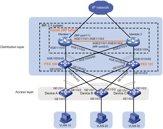
As shown in Figure 1:
· At the distribution layer, set up an IRF 3.1 system in which devices Member 1 and Member 2 is the parent fabric.
· Configure the IRF 3.1 system to provide gateway services for VLANs 10, 20, and 30.
· Connect access layer devices to the PEXs in the IRF 3.1 system through multichassis link aggregation. The PEXs are S5130S-52S-HI switches.
Restrictions and guidelines
To assign extended ports on multiple PEXs to the same Layer 2 extended-link aggregation group, make sure the PEXs meet the following requirements:
· The PEXs belong to the same switch series.
· The PEXs are in the same PEX group.
· The PEXs are at the same tier.
Procedures
Setting up the parent fabric
1. Configure Member 1:
# Set the member ID of Member 1 to 1.
<Sysname> system-view
[Sysname] irf member 1
# Bind Ten-GigabitEthernet 1/0/1 and Ten-GigabitEthernet 1/0/2 to IRF-port 1.
[Sysname] irf-port 1
[Sysname-irf-port1] port group interface ten-gigabitethernet 1/0/1
[Sysname-irf-port1] port group interface ten-gigabitethernet 1/0/2
[Sysname-irf-port1] quit
# Save the running configuration to the next-startup configuration file. The device automatically reboots after you change the device operating mode. The save operation prevents the device from configuration loss after the device reboot.
[Sysname] save
# Enable IRF mode. The mode change takes effect after an automatic device reboot.
[Sysname] chassis convert mode irf
The device will switch to IRF mode and reboot.
You are recommended to save the current running configuration and specify the configuration file for the next startup. Continue? [Y/N]:y
Do you want to convert the content of the next startup configuration file cfa0:/
irf.cfg to make it available in stack mode? [Y/N]:y
Now rebooting, please wait...
2. Configure Member 2:
# Set the member ID of Member 2 to 2.
<Sysname> system-view
[Sysname] irf member 2
# Bind Ten-GigabitEthernet 1/0/1 and Ten-GigabitEthernet 1/0/2 to IRF-port 2.
[Sysname] irf-port 2
[Sysname-irf-port2] port group interface ten-gigabitethernet 1/0/1
[Sysname-irf-port2] port group interface ten-gigabitethernet 1/0/2
[Sysname-irf-port2] quit
# Save the running configuration to the next-startup configuration file.
[Sysname] save
# Connect the IRF physical interfaces of Member 1 and Member 2 as shown in Figure 1.
# Enable IRF mode. The mode change takes effect after an automatic device reboot.
[Sysname] chassis convert mode irf
The device will switch to IRF mode and reboot.
You are recommended to save the current running configuration and specify the configuration file for the next startup. Continue? [Y/N]:y
Do you want to convert the content of the next startup configuration file cfa0:/
irf.cfg to make it available in stack mode? [Y/N]:y
Now rebooting, please wait...
Member 1 and Member 2 perform master election and the device that has failed the master election automatically reboots to form an IRF fabric with the other device.
Configuring cascade ports for PEXs on the parent fabric
# Enter system view.
<Sysname> system-view
# Enable LLDP globally.
[Sysname] lldp global enable
# Create PEX group 1.
[Sysname] pex group 1
[Sysname-pex-group-1] quit
# Create Layer 2 aggregate interface Bridge-Aggregation 100. The aggregate interface will act as the cascade port to the PEX in chassis 100. For easy maintenance, this example assigns the aggregate interface the same interface number as the PEX virtual chassis.
[Sysname] interface bridge-aggregation 100
# Enable PEX connection capability on Bridge-Aggregation 100 and assign Bridge-Aggregation 100 to PEX group 1.
[Sysname-Bridge-Aggregation100] pex-capability enable group 1
The aggregate interface is operating in dynamic aggregation mode and acting as an STP edge port.
# Assign virtual chassis number 100 to the PEX.
[Sysname-Bridge-Aggregation100] pex associate chassis 100
[Sysname-Bridge-Aggregation100] quit
# Enable LLDP on Ten-GigabitEthernet 1/1/0/3 and Ten-GigabitEthernet 2/1/0/3 in interface range view. By default, LLDP is enabled on a port.
[Sysname] interface range ten-gigabitethernet 1/1/0/3 ten-gigabitethernet 2/1/0/3
[Sysname-if-range] lldp enable
# Assign Ten-GigabitEthernet 1/1/0/3 and Ten-GigabitEthernet 2/1/0/3 to aggregation group 100. The ports will act as cascade member interfaces.
[Sysname-if-range] port link-aggregation group 100
[Sysname-if-range] quit
# Create Layer 2 aggregate interface Bridge-Aggregation 101. The aggregate interface will act as the cascade port to the PEX in chassis 101.
[Sysname] interface bridge-aggregation 101
# Enable PEX connection capability on Bridge-Aggregation 101 and assign the interface to PEX group 1.
[Sysname-Bridge-Aggregation101] pex-capability enable group 1
The aggregate interface is operating in dynamic aggregation mode and acting as an STP edge port.
# Assign virtual chassis number 101 to the PEX.
[Sysname-Bridge-Aggregation101] pex associate chassis 101
[Sysname-Bridge-Aggregation101] quit
# Enable LLDP on Ten-GigabitEthernet 1/1/0/4 and Ten-GigabitEthernet 2/1/0/4 in interface range view. By default, LLDP is enabled on a port.
[Sysname] interface range ten-gigabitethernet 1/1/0/4 ten-gigabitethernet 2/1/0/4
[Sysname-if-range] lldp enable
# Assign Ten-GigabitEthernet 1/1/0/4 and Ten-GigabitEthernet 2/1/0/4 to aggregation group 101. The ports will act as cascade member interfaces.
[Sysname-if-range] port link-aggregation group 101
[Sysname-if-range] quit
Configuring PEXs
Configure the devices to be used as PEXs to operate in auto or PEX mode. This example uses PEX 100 to describe the configuration procedure. You configure PEX 101 in the same way PEX 100 is configured.
Prerequisites
A PEX might allow only some interfaces to operate as uplink interfaces depending on its model. Before you configure a PEX, use its configuration and installation guides to select uplink interfaces as appropriate.
In this example, Ten-GigabitEthernet 1/0/49 and Ten-GigabitEthernet 1/0/50 on PEX 100 are used as uplink interfaces.
Procedure
# Change the operating mode to auto mode. By default, the operating mode is auto.
<Sysname> system-view
[Sysname] pex system-working-mode auto
# Save the running configuration.
[Sysname] save
# Connect the uplink interfaces on PEX 100 to the cascade member interfaces on the parent fabric, as shown in Figure 1. (Details not shown.)
Configuring the gateway settings on the IRF 3.1 system
# Enter system view.
<Sysname> system-view
# Create VLANs 10, 20, and 30.
[Sysname] vlan 10 20 30
# Create VLAN-interface 10 and assign IP address 192.168.1.1/24 to the VLAN interface.
[Sysname] interface vlan-interface 10
[Sysname-Vlan-interface10] ip address 192.168.1.1 24
[Sysname-Vlan-interface10] quit
# Create VLAN-interface 20 and assign IP address 192.168.2.1/24 to the VLAN interface.
[Sysname] interface vlan-interface 20
[Sysname-Vlan-interface20] ip address 192.168.2.1 24
[Sysname-Vlan-interface20] quit
# Create VLAN-interface 30 and assign IP address 192.168.3.1/24 to the VLAN interface.
[Sysname] interface vlan-interface 30
[Sysname-Vlan-interface30] ip address 192.168.3.1 24
[Sysname-Vlan-interface30] quit
# Create a Layer 2 extended-link aggregate interface named Bridge-Aggregation 10. The aggregate interface will connect to Device A at the access layer.
[Sysname] interface bridge-aggregation 10 pex
# Assign Bridge-Aggregation 10 to VLAN 10.
[Sysname-Bridge-Aggregation10] port access vlan 10
[Sysname-Bridge-Aggregation10] quit
# Assign GigabitEthernet 100/0/1 and GigabitEthernet 101/0/1 to VLAN 10 and aggregation group 10.
[Sysname] interface range gigabitethernet 100/0/1 gigabitethernet 101/0/1
[Sysname-if-range] port access vlan 10
[Sysname-if-range] port link-aggregation group 10
[Sysname-if-range] quit
# Create a Layer 2 extended-link aggregate interface named Bridge-Aggregation 20. The aggregate interface will connect to Device B at the access layer.
[Sysname] interface bridge-aggregation 20 pex
# Assign Bridge-Aggregation 20 to VLAN 20.
[Sysname-Bridge-Aggregation20] port access vlan 20
[Sysname-Bridge-Aggregation20] quit
# Assign GigabitEthernet 100/0/2 and GigabitEthernet 101/0/2 to VLAN 20 and aggregation group 20.
[Sysname] interface range gigabitethernet 100/0/2 gigabitethernet 101/0/2
[Sysname-if-range] port access vlan 20
[Sysname-if-range] port link-aggregation group 20
[Sysname-if-range] quit
# Create a Layer 2 extended-link aggregate interface named Bridge-Aggregation 30. The aggregate interface will connect to Device C at the access layer.
[Sysname] interface bridge-aggregation 30 pex
# Assign Bridge-Aggregation 30 to VLAN 30.
[Sysname-Bridge-Aggregation30] port access vlan 30
[Sysname-Bridge-Aggregation30] quit
# Assign GigabitEthernet 100/0/3 and GigabitEthernet 101/0/3 to VLAN 30 and aggregation group 30.
[Sysname] interface range gigabitethernet 100/0/3 gigabitethernet 101/0/3
[Sysname-if-range] port access vlan 30
[Sysname-if-range] port link-aggregation group 30
[Sysname-if-range] quit
Configuring access layer devices
1. Configure Device A:
# Enter system view.
<Sysname> system-view
# Create VLAN 10.
[Sysname] vlan 10
[Sysname-vlan10] quit
# Assign GigabitEthernet 1/0/1 through GigabitEthernet 1/0/3 to VLAN 10.
[Sysname] interface range gigabitethernet 1/0/1 to gigabitethernet 1/0/3
[Sysname-if-range] port access vlan 10
[Sysname-if-range] quit
# Create Layer 2 aggregate interface Bridge-Aggregation 1 for connecting to the IRF 3.1 system.
[Sysname] interface bridge-aggregation 1
[Sysname-Bridge-Aggregation1] quit
# Assign GigabitEthernet 1/0/1 and GigabitEthernet 1/0/2 to aggregation group 1.
[Sysname] interface range gigabitethernet 1/0/1 gigabitethernet 1/0/2
[Sysname-if-range] port link-aggregation group 1
[Sysname-if-range] quit
2. Configure Device B:
# Enter system view.
<Sysname> system-view
# Create VLAN 20.
[Sysname] vlan 20
[Sysname-vlan20] quit
# Assign GigabitEthernet 1/0/1 through GigabitEthernet 1/0/3 to VLAN 20.
[Sysname] interface range gigabitethernet 1/0/1 to gigabitethernet 1/0/3
[Sysname-if-range] port access vlan 20
[Sysname-if-range] quit
# Create Layer 2 aggregate interface Bridge-Aggregation 1 for connecting to the IRF 3.1 system.
[Sysname] interface bridge-aggregation 1
[Sysname-Bridge-Aggregation1] quit
# Assign GigabitEthernet 1/0/1 and GigabitEthernet 1/0/2 to aggregation group 1 in interface range view.
[Sysname] interface range gigabitethernet 1/0/1 gigabitethernet 1/0/2
[Sysname-if-range] port link-aggregation group 1
[Sysname-if-range] quit
3. Configure Device C:
# Enter system view.
<Sysname> system-view
# Create VLAN 30.
[Sysname] vlan 30
[Sysname-vlan30] quit
# Assign GigabitEthernet 1/0/1 through GigabitEthernet 1/0/3 to VLAN 30.
[Sysname] interface range gigabitethernet 1/0/1 to gigabitethernet 1/0/3
[Sysname-if-range] port access vlan 30
[Sysname-if-range] quit
# Create Layer 2 aggregate interface Bridge-Aggregation 1 for connecting to the IRF 3.1 system.
[Sysname] interface bridge-aggregation 1
[Sysname-Bridge-Aggregation1] quit
# Assign GigabitEthernet 1/0/1 and GigabitEthernet 1/0/2 to aggregation group 1 in interface range view.
[Sysname] interface range gigabitethernet 1/0/1 gigabitethernet 1/0/2
[Sysname-if-range] port link-aggregation group 1
[Sysname-if-range] quit
Verifying the configuration
# Display device information on the parent fabric. Verify that the output contains information about both the parent fabric and the PEXs.
<Sysname> display device
Slot Type State Subslot Soft Ver Patch Ver
1/0 LSQM3MPUB0 Master 0 S7500E-7536 None
1/1 LSQM2GT24PTSSC0 Normal 0 S7500E-7536 None
1/2 NONE Absent 0 NONE None
1/3 NONE Absent 0 NONE None
1/4 NONE Fault 0 NONE None
1/5 NONE Absent 0 NONE None
1/6 NONE Absent 0 NONE None
1/7 NONE Absent 0 NONE None
PEX in virtual chassis : 100
Slot Type State Subslot Soft Ver Patch Ver
1 S5130S-52S-HI Master 0 S5130-HI6801L01 None
PEX in virtual chassis : 101
Slot Type State Subslot Soft Ver Patch Ver
1 S5130S-52S-HI Master 0 S5130-HI6801L01 None
# Test the gateway service on the IRF 3.1 system. Verify that hosts in VLANs 10, 20, and 30 can ping each other. (Details not shown.)
Configuration files
· IRF 3.1 system:
#
pex group 1
#
lldp global enable
#
vlan 10
#
vlan 20
#
vlan 30
#
irf-port 1/1
port group interface Ten-GigabitEthernet1/1/0/1
port group interface Ten-GigabitEthernet1/1/0/2
#
irf-port 2/2
port group interface Ten-GigabitEthernet2/1/0/1
port group interface Ten-GigabitEthernet2/1/0/2
#
interface Bridge-Aggregation10 pex
port access vlan 10
#
interface Bridge-Aggregation20 pex
port access vlan 20
#
interface Bridge-Aggregation30 pex
port access vlan 30
#
interface Bridge-Aggregation100
pex-capability enable group 1
pex associate chassis 100
link-aggregation mode dynamic
stp edged-port
#
interface Bridge-Aggregation101
pex-capability enable group 1
pex associate chassis 101
link-aggregation mode dynamic
stp edged-port
#
interface Vlan-interface10
ip address 192.168.1.1 255.255.255.0
#
interface Vlan-interface20
ip address 192.168.2.1 255.255.255.0
#
interface Vlan-interface30
ip address 192.168.3.1 255.255.255.0
#
interface GigabitEthernet100/0/1
port link-mode bridge
port access vlan 10
port link-aggregation group 10
#
interface GigabitEthernet100/0/2
port link-mode bridge
port access vlan 20
port link-aggregation group 20
#
interface GigabitEthernet100/0/3
port link-mode bridge
port access vlan 30
port link-aggregation group 30
#
interface GigabitEthernet101/0/1
port link-mode bridge
port access vlan 10
port link-aggregation group 10
#
interface GigabitEthernet101/0/2
port link-mode bridge
port access vlan 20
port link-aggregation group 20
#
interface GigabitEthernet101/0/3
port link-mode bridge
port access vlan 30
port link-aggregation group 30
#
interface Ten-GigabitEthernet1/1/0/3
port link-mode bridge
port link-aggregation group 100
#
interface Ten-GigabitEthernet1/1/0/4
port link-mode bridge
port link-aggregation group 101
#
interface Ten-GigabitEthernet2/1/0/3
port link-mode bridge
port link-aggregation group 100
#
interface Ten-GigabitEthernet2/1/0/4
port link-mode bridge
port link-aggregation group 101
· Device A:
#
vlan 10
#
interface Bridge-Aggregation1
port access vlan 10
#
interface GigabitEthernet1/0/1
port link-mode bridge
port access vlan 10
port link-aggregation group 1
#
interface GigabitEthernet1/0/2
port link-mode bridge
port access vlan 10
port link-aggregation group 1
#
interface GigabitEthernet1/0/3
port link-mode bridge
port access vlan 10
· Device B:
#
vlan 20
#
interface Bridge-Aggregation1
port access vlan 20
#
interface GigabitEthernet1/0/1
port link-mode bridge
port access vlan 20
port link-aggregation group 1
#
interface GigabitEthernet1/0/2
port link-mode bridge
port access vlan 20
port link-aggregation group 1
#
interface GigabitEthernet1/0/3
port link-mode bridge
port access vlan 20
· Device C:
#
vlan 30
#
interface Bridge-Aggregation1
port access vlan 30
#
interface GigabitEthernet1/0/1
port link-mode bridge
port access vlan 30
port link-aggregation group 1
#
interface GigabitEthernet1/0/2
port link-mode bridge
port access vlan 30
port link-aggregation group 1
#
interface GigabitEthernet1/0/3
port link-mode bridge
port access vlan 30
Related documentation
· H3C S7500E Switch Series Virtual Technologies Configuration Guide-R757X
· H3C S7500E Switch Series Virtual Technologies Command Reference-R757X