- Table of Contents
- Related Documents
-
| Title | Size | Download |
|---|---|---|
| 01-PPP commands | 401.78 KB |
ppp compression iphc rtp-connections
ppp compression iphc tcp-connections
remote address dhcp client-identifier
display interface virtual-template
reset counters interface mp-group
reset counters interface virtual-access
display pppoe-server packet statistics
display pppoe-server session packet
display pppoe-server session summary
display pppoe-server throttled-mac
pppoe-server access-line-id bas-info
pppoe-server access-line-id circuit-id parse-mode
pppoe-server access-line-id circuit-id trans-format
pppoe-server access-line-id content
pppoe-server access-line-id remote-id trans-format
pppoe-server access-line-id trust
pppoe-server session-limit per-mac
pppoe-server session-limit per-vlan
pppoe-server session-limit total
pppoe-server tag ppp-max-payload
pppoe-server virtual-template va-pool
reset pppoe-server packet statistics
display pppoe-client session packet
display pppoe-client session summary
reset pppoe-client session packet
PPP and MP commands
This feature is supported only on routers with the following modules installed:
· AM.
· AS.
· ASE.
· BS.
· CE3.
· CPOS.
· CT3.
· E1.
· E1-F.
· POS.
· SAE.
· T1.
· T1-F.
PPP commands
display ip pool
Use display ip pool to display PPP address pools.
Syntax
display ip pool [ pool-name | group group-name ]
Views
Any view
Predefined user roles
network-admin
network-operator
Parameters
pool-name: Specifies a PPP address pool by its name, a case-sensitive string of 1 to 31 characters.
group group-name: Displays PPP address pools in a group specified by its name, a case-sensitive string of 1 to 31 characters.
Usage guidelines
If you do not specify any parameters, the command displays brief information about all PPP address pools.
If you specify an address pool, the command displays detailed information about the specified PPP address pool.
Examples
# Display brief information about all PPP address pools.
<Sysname> display ip pool
Group name: a
Pool name Start IP address End IP address Free In use
aaa1 1.1.1.1 1.1.1.5 5 0
aaa2 1.1.1.6 1.1.1.10 5 0
Group name: b
Pool name Start IP address End IP address Free In use
bbb 1.1.2.1 1.1.2.5 4 1
2.2.2.1 2.2.2.5 5 0
# Display brief information about the PPP address pools in group a.
<Sysname> display ip pool group a
Group name: a
Pool name Start IP address End IP address Free In use
aaa1 1.1.1.1 1.1.1.5 5 0
aaa2 1.1.1.6 1.1.1.10 5 0
# Display detailed information about PPP address pool bbb.
<Sysname> display ip pool bbb
Group name: b
Pool name Start IP address End IP address Free In use
bbb 1.1.2.1 1.1.2.5 4 1
2.2.2.1 2.2.2.5 5 0
In use IP addresses:
IP address Interface
1.1.2.1 POS2/2/0
# Display detailed information about PPP address pool bbb.
<Sysname> display ip pool bbb
Group name: b
Pool name Start IP address End IP address Free In use
bbb 1.1.2.1 1.1.2.5 4 1
2.2.2.1 2.2.2.5 5 0
In use IP addresses:
IP address Interface
1.1.2.1 Virtual-Template1
Table 1 Command output
|
Field |
Description |
|
Free |
Number of free IP addresses. |
|
In use |
Number of IP addresses that have been assigned. |
|
In use IP addresses |
Information about the IP addresses that have been assigned. |
|
Interface |
Local interface that requests the IP address for the peer interface. |
Related commands
ip pool
display ppp access-user
Use display ppp access-user to display PPP user information.
Syntax
display ppp access-user { interface interface-type interface-number [ count ] | ip-address ipv4-address | ipv6-address ipv6-address| username user-name | user-type { lac | lns | pppoa| pppoe } [ count ] }
Views
Any view
Predefined user roles
network-admin
network-operator
Parameters
interface interface-type interface-number: Displays brief information about PPP users on the specified interface.
ip-address ipv4-address: Displays detailed information about the PPP user specified by its IPv4 address.
ipv6-address ipv6-address: Displays detailed information about the PPP user specified by its IPv6 address.
username user-name: Displays detailed information about the PPP user specified by its username, a case-sensitive string of 1 to 80 characters.
user-type: Displays brief information about online users of the specified type.
lac: Displays brief information about L2TP users for an LAC.
lns: Displays brief information about L2TP users for an LNS.
pppoa: Displays brief information about PPPoA users.
pppoe: Displays brief information about PPPoE users.
count: Displays the total number of PPP users matching the specified criterion.
Usage guidelines
Brief information about a PPP user includes the following:
· Brief name of the VA interface.
· Username.
· MAC address.
· IPv4 address, IPv6 address, or IPv6 prefix of the PPP user.
Detailed information about a PPP user includes the following:
· Brief name of the VA interface.
· User ID.
· Username.
· Authentication information.
· Uplink and downlink traffic.
· Access start time of the PPP user.
In an L2TP network, this command is supported on an LAC only when a remote system dials in to the LAC through a PPPoE network. For more information about L2TP, see "Configuring L2TP."
Examples
# Display brief information about PPP users on GigabitEthernet 1/0/1.
<Sysname> display ppp access-user interface gigabitethernet 1/0/1
Interface Username MAC address IP address IPv6 address IPv6 PDPrefix
VA0 user1@dm1 0001-0101-9101 192.168.100.173 - -
VA1 user2@dm2 0001-0101-9101 192.168.80.173 2000::1 -
# Display the total number of PPP users on GigabitEthernet 1/0/1.
<Sysname> display ppp access-user interface gigabitethernet 1/0/1 count
Total users: 2
Table 2 Command output
|
Field |
Description |
|
Interface |
Name of the VA interface corresponding to the user. |
|
Username of the user. A hyphen (-) means that the user does not need authentication. |
|
|
MAC address |
MAC address of the user. A hyphen (-) means that the user is not a PPPoE user. |
|
IP address |
IP address of the user. A hyphen (-) means that no IP address is assigned to the user. |
|
IPv6 address |
IPv6 address of the user. A hyphen (-) means that no IPv6 address is assigned to the user. |
|
IPv6 PD prefix |
IPv6 prefix of the user. A hyphen (-) means that no IPv6 prefix is assigned to the user. |
|
Total users |
Total number of PPP users. |
# Display detailed information about the PPP user whose IP address is 50.50.50.3.
<Sysname> display ppp access-user ip-address 50.50.50.3
Basic:
Interface: VA0
User ID: 0x28000002
Username: user1@hrss
Domain: hrss
Access interface: RAGG2
Service-VLAN/Customer-VLAN: -/-
MAC address: 0000-0000-0001
IP address: 50.50.50.3
IPv6 address: -
IPv6 PD prefix: -
VPN instance: 123
Access type: PPPoE
Authentication type: CHAP
AAA:
Authentication state: Authenticated
Authorization state: Authorized
Realtime accounting switch: Open
Realtime accounting interval: 60s
Login time: 2013-1-19 2:42:3:358
Accounting start time: 2013-1-19 2:42:3:382
Online time(hh:mm:ss): 0:7:34
Accounting state: Accounting
Idle cut: 0 sec 0 byte
Session timeout: 12000 s
Time remained: 8000 s
Byte remained: 20971520 bytes
Redirect WebURL: http://6.6.6.6
ACL&QoS:
User profile: profile123 (active)
User group profile: -
Inbound CAR: CIR 64000bps PIR 640000bps CBS 500bit
Outbound CAR: CIR 64000bps PIR 640000bps CBS 500bit
NAT:
Global IP address: 111.8.0.200
Port block: 28744-28748
Flow Statistic:
IPv4 uplink packets/bytes: 7/546
IPv4 downlink packets/bytes: 0/0
IPv6 uplink packets/bytes: 0/0
IPv6 downlink packets/bytes: 0/0
ITA:
Level-1 uplink packets/bytes: 100/128000
downlink packets/bytes: 200/256000
Level-2 uplink packets/bytes: 100/128000
downlink packets/bytes: 200/256000
Table 3 Command output
|
Field |
Description |
|
Basic |
Basic information. |
|
Interface |
Brief name of the VA interface that corresponds to the user. |
|
Username |
Username of the user. A hyphen (-) means that the user does not need authentication. |
|
Domain |
ISP domain name for authentication. A hyphen (-) means that no ISP domain is specified for authentication. |
|
Access interface |
Name of the access interface of the user. |
|
Service-VLAN/Customer-VLAN |
Service provider VLAN and customer VLAN information of the user. A hyphen (-) means that no VLAN information is available. |
|
IP address |
IP address of the user. A hyphen (-) means that no IP address is assigned to the user. |
|
IPv6 address |
IPv6 address of the user. A hyphen (-) means that no IPv6 address is assigned to the user. |
|
IPv6 PD prefix |
Delegated IPv6 prefix of the user. A hyphen (-) means that no delegated IPv6 prefix is assigned to the user. |
|
VPN instance |
VPN instance to which the user belongs. A hyphen (-) means that the user is not bound to any VPN instance. |
|
Access type |
Access type of the user: · PPPoE. · PPPoA. · L2TP. |
|
Authentication type |
Authentication type of the user: · PAP. · CHAP. · MS-CHAP. · MS-CHAP-V2. |
|
Authentication state |
Authentication state of the user: · Idle—The user has not been authenticated. · Authenticating—The user is being authenticated. · Authenticated—The user has been authenticated. |
|
Authorization state |
Authorization state of the user: · Idle—The user has not been authorized. · Authorizing—The user is being authorized. · Authorized—The user has been authorized. |
|
Realtime accounting switch |
· Open—The switch is on. · Closed—The switch is off. |
|
Realtime accounting interval |
Realtime accounting interval in seconds. A hyphen (-) means that no real-time accounting interval is authorized. |
|
Login time |
Time when the user accessed the device through PPP. |
|
Accounting start time |
Time when accounting started. A hyphen (-) means that no accounting is performed on the user. |
|
Online time(hh:mm:ss) |
Online duration of the current login. |
|
Accounting state |
Accounting state of the user: · Accounting—Accounting is on. · Stop—Accounting stops. |
|
Idle cut |
Traffic threshold for logging off the user in idle state. If the traffic is less than the threshold within the specified period, the user is forcibly logged off. |
|
Session timeout |
Authorization time for the user, in seconds. A hyphen (-) means that no authorization time is specified for the user. |
|
Time remained |
Remaining time for the user to stay online, in seconds. A hyphen (-) means that no authorization time is specified for the user. |
|
Byte remained |
Remaining traffic for the user. A hyphen (-) means that no authorization traffic is specified for the user. |
|
Redirect WebURL |
Redirect Web URL address for the user. A hyphen (-) means that no redirect Web URL address is specified for the user. |
|
User profile |
Name of the authorized user profile. The hyphen (-) means that no user profile is authorized. The user profile has two states: · active—The authorized user profile is successfully issued. · inactive—The authorized user profile fails to be issued. |
|
User group profile |
Name of the authorized user group profile. The hyphen (-) means that no user group profile is authorized. The user group profile has two states: · active—The authorized user group profile is successfully issued. · inactive—The authorized user group profile fails to be issued. |
|
Inbound CAR |
Authorized inbound CAR parameters, which contain the CIR (in bps), the PIR (in bps), and the CBS (in bits). |
|
Outbound CAR |
Authorized outbound CAR parameters, which contain the CIR (in bps), the PIR (in bps), and the CBS (in bits). |
|
Global IP address |
Global IP address of the user. This field is displayed if NAT444 is used. For information about NAT444, see Layer 3—IP Services Configuration Guide. |
|
Port block |
Port block of the user, from the start port to the end port. This field is displayed if NAT444 is used. |
|
IPv4 uplink packets/bytes |
Number of packets and bytes for IPv4 uplink traffic. |
|
IPv4 downlink packets/bytes |
Number of packets and bytes for IPv4 downlink traffic. |
|
IPv6 uplink packets/bytes |
Number of packets and bytes for IPv6 uplink traffic. |
|
IPv6 downlink packets/bytes |
Number of packets and bytes for IPv6 downlink traffic. |
|
ITA |
ITA statistics. ITA statistics are displayed after ITA is enabled. If the traffic-separate enable command is configured, ITA statistics are not included in flow statistics. For information about ITA and the traffic-separate enable command, see Security Configuration Guide. |
|
Level-n uplink packets/bytes downlink packets/bytes |
Number of packets and bytes for uplink traffic at accounting level n. The value for n depends on the traffic level command, and its value range is 1 to 8. |
Related commands
reset ppp access-user
display ppp compression iphc
Use display ppp compression iphc to display IP header compression (IPHC) statistics.
Syntax
display ppp compression iphc { rtp | tcp } [ interface interface-type interface-number ]
Views
Any view
Predefined user roles
network-admin
network-operator
Parameters
rtp: Displays IPHC RTP header compression statistics.
tcp: Displays IPHC TCP header compression statistics.
interface interface-type interface-number: Specifies an interface by its type and number. If you do not specify this option, the command displays IPHC statistics on all interfaces.
Usage guidelines
When IPHC applies to an MP link:
· If an MP template is used, such as a VT interface or a dialer interface, the associated VA interface performs IPHC. You can view the compression information on the VA interface.
· If an MP-group interface is used, the MP-group interface performs IPHC. You can view the compression information on the MP-group interface.
When IPHC applies to a normal PPP link, the physical interface performs IPHC. You can view the compression information on the physical interface.
Examples
# (In standalone mode.) Display IPHC RTP header compression statistics.
<Sysname> display ppp compression iphc rtp
----------------------Slot1----------------------
Interface: Virtual-Access0
Received:
Compressed/Error/Total: 0/0/0 packets
Sent:
Compressed/Total: 0/0 packets
Sent/Saved/Total: 0/0/0 bytes
Packet-based compression ratio: 0%
Byte-based compression ratio: 0%
Connections:
Rx/Tx: 16/16
Five-Minute-Miss: 0 (Misses/5Mins)
Max-Miss: 0
----------------------Slot2----------------------
Interface: Virtual-Access0
Received:
Compressed/Error/Total: 20/5/40 packets
Sent:
Compressed/Total: 34/40 packets
Sent/Saved/Total: 1131/1210/2341 bytes
Packet-based compression ratio: 85%
Byte-based compression ratio: 51%
Connections:
Rx/Tx: 16/16
Five-Minute-Miss: 0 (Misses/5Mins)
Max-Miss: 0
# (In standalone mode.) Display IPHC TCP header compression statistics.
<Sysname>display ppp compression iphc tcp
----------------------Slot1----------------------
Interface: Virtual-Access0
Received:
Compressed/Error/Total: 0/0/0 packets
Sent:
Compressed/Total: 0/0 packets
Sent/Saved/Total: 0/0/0 bytes
Packet-based compression ratio: 0%
Byte-based compression ratio: 0%
Connections:
Rx/Tx: 16/16
Five-Minute-Miss: 0 (Misses/5Mins)
Max-Miss: 0
----------------------Slot2----------------------
Interface: Virtual-Access0
Received:
Compressed/Error/Total: 20/5/40 packets
Sent:
Compressed/Total: 34/40 packets
Sent/Saved/Total: 1131/1210/2341 bytes
Packet-based compression ratio: 85%
Byte-based compression ratio: 51%
Connections:
Rx/Tx: 16/16
Five-Minute-Miss: 0 (Misses/5Mins)
Max-Miss: 0
Table 4 Command output
|
Field |
Description |
|
Received: Compressed/Error/Total |
Statistics for received packets: · Compressed—Number of compressed packets. · Error—Number of error packets. · Total—Total number of received packets. |
|
Sent: Compressed/Total Sent/Saved/Total Packet-based compression ratio Byte-based compression ratio |
Statistics for sent packets: · Compressed—Number of compressed packets. · Total—Total number of sent packets. · Sent—Bytes of sent packets. · Saved—Bytes of saved packets. · Total—Total bytes to be sent if packets are not compressed. · Packet-based compression ratio—Ratio of compressed packets to the total sent packets. · Byte-based compression ratio—Ratio of saved bytes to the total sent bytes. |
|
Connections: Rx/Tx Five-Minute-Miss Max-Miss |
Number of connections. · Rx—Number of connections that the receiver can decompress. · Tx—Number of connections that the sender can compress. · Five-Minute-Miss—Number of search failures within the last 5 minutes. · Max-Miss—Maximum number of search failures within 5 minutes. |
Related commands
ppp compression iphc enable
reset ppp compression iphc
display ppp packet statistics
Use display ppp packet statistics to display PPP negotiation packet statistics.
Syntax
In standalone mode:
display ppp packet statistics [ slot slot-number ]
In IRF mode:
display ppp packet statistics [ chassis chassis-number slot slot-number ]
Views
Any view
Predefined user roles
network-admin
network-operator
Parameters
slot slot-number: Specifies a card by its slot number. If you do not specify a card, this command displays PPP negotiation packet statistics for all cards. (In standalone mode.)
chassis chassis-number slot slot-number: Specifies a card on an IRF member device. The chassis-number argument represents the member ID of the IRF member device. The slot-number argument represents the slot number of the card. If you do not specify a card, this command displays PPP negotiation packet statistics for all cards. (In IRF mode.)
Examples
# (In standalone mode.) Display PPP negotiation packet statistics for slot 1.
<Sysname> display ppp packet statistics slot 1
PPP packet statistics in slot 1:
-------------------------------LCP------------------------------------
SEND_LCP_CON_REQ : 0 RECV_LCP_CON_REQ : 0
SEND_LCP_CON_NAK : 0 RECV_LCP_CON_NAK : 0
SEND_LCP_CON_REJ : 0 RECV_LCP_CON_REJ : 0
SEND_LCP_CON_ACK : 0 RECV_LCP_CON_ACK : 0
SEND_LCP_CODE_REJ : 0 RECV_LCP_CODE_REJ : 0
SEND_LCP_PROT_REJ : 0 RECV_LCP_PROT_REJ : 0
SEND_LCP_TERM_REQ : 0 RECV_LCP_TERM_REQ : 0
SEND_LCP_TERM_ACK : 0 RECV_LCP_TERM_ACK : 0
SEND_LCP_ECHO_REQ : 0 RECV_LCP_ECHO_REQ : 0
SEND_LCP_ECHO_REP : 0 RECV_LCP_ECHO_REP : 0
SEND_LCP_FAIL : 0
-------------------------------IPCP-----------------------------------
SEND_IPCP_CON_REQ : 0 RECV_IPCP_CON_REQ : 0
SEND_IPCP_CON_NAK : 0 RECV_IPCP_CON_NAK : 0
SEND_IPCP_CON_REJ : 0 RECV_IPCP_CON_REJ : 0
SEND_IPCP_CON_ACK : 0 RECV_IPCP_CON_ACK : 0
SEND_IPCP_CODE_REJ : 0 RECV_IPCP_CODE_REJ : 0
SEND_IPCP_PROT_REJ : 0 RECV_IPCP_PROT_REJ : 0
SEND_IPCP_TERM_REQ : 0 RECV_IPCP_TERM_REQ : 0
SEND_IPCP_TERM_ACK : 0 RECV_IPCP_TERM_ACK : 0
SEND_IPCP_FAIL : 0
-------------------------------IPV6CP---------------------------------
SEND_IPV6CP_CON_REQ : 0 RECV_IPV6CP_CON_REQ : 0
SEND_IPV6CP_CON_NAK : 0 RECV_IPV6CP_CON_NAK : 0
SEND_IPV6CP_CON_REJ : 0 RECV_IPV6CP_CON_REJ : 0
SEND_IPV6CP_CON_ACK : 0 RECV_IPV6CP_CON_ACK : 0
SEND_IPV6CP_CODE_REJ : 0 RECV_IPV6CP_CODE_REJ : 0
SEND_IPV6CP_PROT_REJ : 0 RECV_IPV6CP_PROT_REJ : 0
SEND_IPV6CP_TERM_REQ : 0 RECV_IPV6CP_TERM_REQ : 0
SEND_IPV6CP_TERM_ACK : 0 RECV_IPV6CP_TERM_ACK : 0
SEND_IPV6CP_FAIL : 0
-------------------------------OSICP---------------------------------
SEND_OSICP_CON_REQ : 0 RECV_OSICP_CON_REQ : 0
SEND_OSICP_CON_NAK : 0 RECV_OSICP_CON_NAK : 0
SEND_OSICP_CON_REJ : 0 RECV_OSICP_CON_REJ : 0
SEND_OSICP_CON_ACK : 0 RECV_OSICP_CON_ACK : 0
SEND_OSICP_CODE_REJ : 0 RECV_OSICP_CODE_REJ : 0
SEND_OSICP_PROT_REJ : 0 RECV_OSICP_PROT_REJ : 0
SEND_OSICP_TERM_REQ : 0 RECV_OSICP_TERM_REQ : 0
SEND_OSICP_TERM_ACK : 0 RECV_OSICP_TERM_ACK : 0
SEND_OSICP_FAIL : 0
-------------------------------MPLSCP---------------------------------
SEND_MPLSCP_CON_REQ : 0 RECV_MPLSCP_CON_REQ : 0
SEND_MPLSCP_CON_NAK : 0 RECV_MPLSCP_CON_NAK : 0
SEND_MPLSCP_CON_REJ : 0 RECV_MPLSCP_CON_REJ : 0
SEND_MPLSCP_CON_ACK : 0 RECV_MPLSCP_CON_ACK : 0
SEND_MPLSCP_CODE_REJ : 0 RECV_MPLSCP_CODE_REJ : 0
SEND_MPLSCP_PROT_REJ : 0 RECV_MPLSCP_PROT_REJ : 0
SEND_MPLSCP_TERM_REQ : 0 RECV_MPLSCP_TERM_REQ : 0
SEND_MPLSCP_TERM_ACK : 0 RECV_MPLSCP_TERM_ACK : 0
SEND_MPLSCP_FAIL : 0
--------------------------------AUTH ----------------------------------
SEND_PAP_AUTH_REQ : 0 RECV_PAP_AUTH_REQ : 0
SEND_PAP_AUTH_ACK : 0 RECV_PAP_AUTH_ACK : 0
SEND_PAP_AUTH_NAK : 0 RECV_PAP_AUTH_NAK : 0
SEND_CHAP_AUTH_CHALLENGE : 0 RECV_CHAP_AUTH_CHALLENGE : 0
SEND_CHAP_AUTH_RESPONSE : 0 RECV_CHAP_AUTH_RESPONSE : 0
SEND_CHAP_AUTH_ACK : 0 RECV_CHAP_AUTH_ACK : 0
SEND_CHAP_AUTH_NAK : 0 RECV_CHAP_AUTH_NAK : 0
SEND_PAP_AUTH_FAIL : 0 SEND_CHAP_AUTH_FAIL : 0
Table 5 Command output
|
Field |
Description |
|
LCP |
LCP packet statistics. · SEND_LCP_CON_REQ—Number of sent link configuration request packets. · RECV_LCP_CON_REQ—Number of received link configuration request packets. · SEND_LCP_CON_NAK—Number of sent link configuration NAK packets. · RECV_LCP_CON_NAK—Number of received link configuration NAK packets. · SEND_LCP_CON_REJ—Number of sent link configuration reject packets. · RECV_LCP_CON_REJ—Number of received link configuration reject packets. · SEND_LCP_CON_ACK—Number of sent link configuration ACK packets. · RECV_LCP_CON_ACK—Number of received link configuration ACK packets. · SEND_LCP_CODE_REJ—Number of sent link configuration code reject packets. · RECV_LCP_CODE_REJ—Number of received link configuration code reject packets. · SEND_LCP_PROT_REJ—Number of sent link configuration protocol reject packets. · RECV_LCP_PROT_REJ—Number of received link configuration protocol reject packets. · SEND_LCP_TERM_REQ—Number of sent link termination request packets. · RECV_LCP_TERM_REQ—Number of received link termination request packets. · SEND_LCP_TERM_ACK—Number of sent link termination ACK packets. · RECV_LCP_TERM_ACK—Number of received link termination ACK packets. · SEND_LCP_ECHO_REQ—Number of sent LCP echo request packets. · RECV_LCP_ECHO_REQ—Number of received LCP echo request packets. · SEND_LCP_ECHO_REP—Number of sent LCP echo reply packets. · RECV_LCP_ECHO_REP—Number of received LCP echo reply packets. · SEND_LCP_FAIL—Number of sent link failure packets. |
|
IPCP |
IPCP packet statistics. · SEND_IPCP_CON_REQ—Number of sent IP address negotiation request packets. · RECV_IPCP_CON_REQ—Number of received IP address negotiation request packets. · SEND_IPCP_CON_NAK—Number of sent IP address negotiation NAK packets. · RECV_IPCP_CON_NAK—Number of received IP address negotiation NAK packets. · SEND_IPCP_CON_REJ—Number of sent IP address negotiation reject packets. · RECV_IPCP_CON_REJ—Number of received IP address negotiation reject packets. · SEND_IPCP_CON_ACK—Number of sent IP address negotiation ACK packets. · RECV_IPCP_CON_ACK—Number of received IP address negotiation ACK packets. · SEND_IPCP_CODE_REJ—Number of sent IP address negotiation code reject packets. · RECV_IPCP_CODE_REJ—Number of received IP address negotiation code reject packets. · SEND_IPCP_PROT_REJ—Number of sent IP address negotiation protocol reject packets. · RECV_IPCP_PROT_REJ—Number of received IP address negotiation protocol reject packets. · SEND_IPCP_TERM_REQ—Number of sent IP address negotiation termination request packets. · RECV_IPCP_TERM_REQ—Number of received IP address negotiation termination request packets. · SEND_IPCP_TERM_ACK—Number of sent IP address negotiation termination ACK packets. · RECV_IPCP_TERM_ACK—Number of received IP address negotiation termination ACK packets. · SEND_IPCP_FAIL—Number of sent IP address negotiation failure packets. |
|
IPV6CP |
IPv6CP packet statistics. · SEND_IPV6CP_CON_REQ—Number of sent IPv6 address negotiation request packets. · RECV_IPV6CP_CON_REQ—Number of received IPv6 address negotiation request packets. · SEND_IPV6CP_CON_NAK—Number of sent IPv6 address negotiation NAK packets. · RECV_IPV6CP_CON_NAK—Number of received IPv6 address negotiation NAK packets. · SEND_IPV6CP_CON_REJ—Number of sent IPv6 address negotiation reject packets. · RECV_IPV6CP_CON_REJ—Number of received IPv6 address negotiation reject packets. · SEND_IPV6CP_CON_ACK—Number of sent IPv6 address negotiation ACK packets. · RECV_IPV6CP_CON_ACK—Number of received IPv6 address negotiation ACK packets. · SEND_IPV6CP_CODE_REJ—Number of sent IPv6 address negotiation code reject packets. · RECV_IPV6CP_CODE_REJ—Number of received IPv6 address negotiation code reject packets. · SEND_IPV6CP_PROT_REJ—Number of sent IPv6 address negotiation protocol reject packets. · RECV_IPV6CP_PROT_REJ—Number of received IPv6 address negotiation protocol reject packets. · SEND_IPV6CP_TERM_REQ—Number of sent IPv6 address negotiation termination request packets. · RECV_IPV6CP_TERM_REQ—Number of received IPv6 address negotiation termination request packets. · SEND_IPV6CP_TERM_ACK—Number of sent IPv6 address negotiation termination ACK packets. · RECV_IPV6CP_TERM_ACK—Number of received IPv6 address negotiation termination ACK packets. · SEND_IPV6CP_FAIL—Number of sent IPv6 address negotiation failure packets. |
|
OSICP |
OSICP packet statistics. · SEND_OSICP_CON_REQ—Number of sent OSI address negotiation request packets. · RECV_OSICP_CON_REQ—Number of received OSI address negotiation request packets. · SEND_OSICP_CON_NAK—Number of sent OSI address negotiation NAK packets. · RECV_OSICP_CON_NAK—Number of received OSI address negotiation NAK packets. · SEND_OSICP_CON_REJ—Number of sent OSI address negotiation reject packets. · RECV_OSICP_CON_REJ—Number of received OSI address negotiation reject packets. · SEND_OSICP_CON_ACK—Number of sent OSI address negotiation ACK packets. · RECV_OSICP_CON_ACK—Number of received OSI address negotiation ACK packets. · SEND_OSICP_CODE_REJ—Number of sent OSI address negotiation code reject packets. · RECV_OSICP_CODE_REJ—Number of received OSI address negotiation code reject packets. · SEND_OSICP_PROT_REJ—Number of sent OSI address negotiation protocol packets. · RECV_OSICP_PROT_REJ—Number of received OSI address negotiation protocol reject packets. · SEND_OSICP_TERM_REQ—Number of sent OSI address negotiation termination request packets. · RECV_OSICP_TERM_REQ—Number of received OSI address negotiation termination request packets. · SEND_OSICP_TERM_ACK—Number of sent OSI address negotiation termination ACK packets. · RECV_OSICP_TERM_ACK—Number of received OSI address negotiation termination ACK packets. · SEND_OSICP_FAIL—Number of sent OSI address negotiation failure packets. |
|
MPLSCP |
MPLSCP packet statistics. · SEND_MPLSCP_CON_REQ—Number of sent MPLS address negotiation request packets. · RECV_MPLSCP_CON_REQ—Number of received MPLS address negotiation request packets. · SEND_MPLSCP_CON_NAK—Number of sent MPLS address negotiation NAK packets. · RECV_MPLSCP_CON_NAK—Number of received MPLS address negotiation NAK packets. · SEND_MPLSCP_CON_REJ—Number of sent MPLS address negotiation reject packets. · RECV_MPLSCP_CON_REJ—Number of received MPLS address negotiation reject packets. · SEND_MPLSCP_CON_ACK—Number of sent MPLS address negotiation ACK packets. · RECV_MPLSCP_CON_ACK—Number of received MPLS address negotiation ACK packets. · SEND_MPLSCP_CODE_REJ—Number of sent MPLS address negotiation code reject packets. · RECV_MPLSCP_CODE_REJ—Number of received MPLS address negotiation code reject packets. · SEND_MPLSCP_PROT_REJ—Number of sent MPLS address negotiation protocol packets. · RECV_MPLSCP_PROT_REJ—Number of received MPLS address negotiation protocol reject packets. · SEND_MPLSCP_TERM_REQ—Number of sent MPLS address negotiation termination request packets. · RECV_MPLSCP_TERM_REQ—Number of received MPLS address negotiation termination request packets. · SEND_MPLSCP_TERM_ACK—Number of sent MPLS address negotiation termination ACK packets. · RECV_MPLSCP_TERM_ACK—Number of received MPLS address negotiation termination ACK packets. · SEND_MPLSCP_FAIL—Number of sent MPLS address negotiation failure packets. |
|
AUTH |
Authentication packet statistics. · SEND_PAP_AUTH_REQ—Number of sent PAP authentication request packets. · RECV_PAP_AUTH_REQ—Number of received PAP authentication request packets. · SEND_PAP_AUTH_ACK—Number of sent PAP authentication ACK packets. · RECV_PAP_AUTH_ACK—Number of received PAP authentication ACK packets. · SEND_PAP_AUTH_NAK—Number of sent PAP authentication NAK packets. · RECV_PAP_AUTH_NAK—Number of received PAP authentication NAK packets. · SEND_CHAP_AUTH_CHALLENGE—Number of sent CHAP authentication request packets. · RECV_CHAP_AUTH_CHALLENGE—Number of received CHAP authentication request packets. · SEND_CHAP_AUTH_RESPONSE—Number of sent CHAP authentication response packets. · RECV_CHAP_AUTH_RESPONSE—Number of received CHAP authentication response packets. · SEND_CHAP_AUTH_ACK—Number of sent CHAP authentication ACK packets. · RECV_CHAP_AUTH_ACK—Number of received CHAP authentication ACK packets. · SEND_CHAP_AUTH_NAK—Number of sent CHAP authentication NAK packets. · RECV_CHAP_AUTH_NAK—Number of received CHAP authentication NAK packets. · SEND_PAP_AUTH_FAIL—Number of sent PAP authentication failure packets. · SEND_CHAP_AUTH_FAIL—Number of sent CHAP authentication failure packets. |
Related commands
reset ppp packet statistics
ip address ppp-negotiate
Use ip address ppp-negotiate to enable IP address negotiation on an interface, so that the interface can accept the IP address allocated by the server.
Use undo ip address ppp-negotiate to restore the default.
Syntax
ip address ppp-negotiate
undo ip address ppp-negotiate
Default
IP address negotiation is disabled on an interface.
Views
Interface view
Predefined user roles
network-admin
Usage guidelines
If you execute the ip address ppp-negotiate and ip address commands multiple times, the most recent configuration takes effect.
Examples
# Enable IP address negotiation on Serial 2/1/0.
<Sysname> system-view
[Sysname] interface serial 2/1/0
[Sysname-Serial2/1/0] ip address ppp-negotiate
# Enable IP address negotiation on Virtual-Template 1.
<Sysname> system-view
[Sysname] interface virtual-template 1
[Sysname-Virtual-Template1] ip address ppp-negotiate
ip address (Layer 3—IP Services Command Reference)
remote address
ip pool
Use ip pool to configure a PPP address pool.
Use undo ip pool to remove a PPP address pool or an IP address range of the PPP address pool.
Syntax
ip pool pool-name start-ip-address [ end-ip-address ] [ group group-name ]
undo ip pool pool-name [ start-ip-address [ end-ip-address ] ]
Default
No PPP address pool is configured.
Views
System view
Predefined user roles
network-admin
Parameters
pool-name: Specifies a name for the PPP address pool to be created, a case-sensitive string of 1 to 31 characters.
start-ip-address [ end-ip-address ]: Specifies an IP address range. If you do not specify the end-ip-address argument, the PPP address pool has only the start IP address.
group group-name: Specifies a group by its name to which the PPP address pool belongs. The group name is a case-sensitive string of 1 to 31 characters. If you do not specify this option, the group name is default (the default group).
Usage guidelines
The system supports multiple address spaces that each correspond to a VPN instance. The same IP addresses can exist in different address spaces.
Each address space is represented by a group. One group can contain multiple PPP address pools, but one PPP address pool can belong to only one group.
One PPP address pool can contain multiple IP address ranges. You can execute this command multiple times to specify multiple IP address ranges for a PPP address pool. A PPP address pool can contain a maximum of 65535 IP addresses, and so can an IP address range.
IP address ranges in different groups can be overlapping, but those in the same group cannot.
Changes to a PPP address pool do not affect assigned IP addresses. For example, if you delete a PPP address pool from which an IP address has been assigned, the IP address can still be used.
When assigning IP address to users through a PPP address pool, make sure the PPP address pool excludes the gateway IP address of the PPP address pool.
Examples
# Configure PPP address pool aaa that contains IP addresses 129.102.0.1 through 129.102.0.10 for group a.
<Sysname> system-view
[Sysname] ip pool aaa 129.102.0.1 129.102.0.10 group a
Related commands
display ip pool
ip pool gateway
Use ip pool gateway to configure a gateway address for a PPP address pool.
Use undo ip pool gateway to remove the gateway address for the specified PPP address pool.
Syntax
ip pool pool-name gateway ip-address [ vpn-instance vpn-instance-name ]
undo ip pool pool-name gateway
Default
A PPP address pool is not configured with a gateway address.
Views
System view
Predefined user roles
network-admin
Parameters
pool-name: Specifies an existing PPP address pool by its name, a case-sensitive string of 1 to 31 characters.
ip-address: Specifies a gateway address for the PPP address pool.
vpn-instance vpn-instance-name: Specifies an existing MPLS L3VPN instance by its name, a case-sensitive string of 1 to 31 characters. If you do not specify this option, the specified gateway belongs to the public network.
Usage guidelines
An interface on a BRAS must have an IP address before it can assign an IP address from a PPP or DHCP address pool to a client. This command enables interfaces that have no IP address to use a gateway address for IPCP negotiation and address allocation.
When you configure a gateway address for a PPP address pool, follow these restrictions and guidelines:
· If you also specify an IP address for an interface, the interface uses its own IP address to perform IPCP negotiation.
· You can specify only one gateway address for a PPP address pool. Different PPP address pools must have different gateway addresses (different combinations of ip-address and vpn-instance-name).
· You can specify any gateway address for a PPP address pool.
Examples
# Specify gateway address 1.1.1.1 for PPP address pool aaa.
<Sysname> system-view
[Sysname] ip pool aaa gateway 1.1.1.1
Related commands
ip pool
link-protocol ppp
Use link-protocol ppp to enable PPP encapsulation on an interface.
Syntax
link-protocol ppp
Default
PPP encapsulation is enabled on all interfaces except Ethernet, VLAN, and ATM interfaces.
Views
Interface view
Predefined user roles
network-admin
Examples
# Enable PPP encapsulation on Serial 2/1/0.
<Sysname> system-view
[Sysname] interface serial 2/1/0
[Sysname-Serial2/1/0] link-protocol ppp
nas-port-type
Use nas-port-type to configure the NAS-Port-Type attribute on a VT interface.
Use undo nas-port-type to restore the default.
Syntax
nas-port-type { 802.11 | adsl-cap | adsl-dmt | async | cable | ethernet | g.3-fax | hdlc | idsl | isdn-async-v110 | isdn-async-v120 | isdn-sync | piafs | sdsl | sync | virtual | wireless-other | x.25 | x.75 | xdsl }
undo nas-port-type
Default
The NAS-Port-Type attribute is determined by the service type and link type of the PPP user, as shown in Table 6.
Table 6 Default NAS-Port-Type attribute
|
Service type |
Link type |
NAS-Port-Type attribute |
|
PPPoE |
VEth interface |
xdsl |
|
Other interfaces |
ethernet |
|
|
PPPoA |
Any |
xdsl |
|
L2TP |
Any |
virtual |
Views
VT interface view
Predefined user roles
network-admin
Parameters
802.11: Specifies IEEE 802.11. The code value is 19.
adsl-cap: Specifies asymmetric DSL, Carrierless Amplitude Phase. The code value is 12.
adsl-dmt: Specifies asymmetric DSL, Discrete Multi-Tone. The code value is 13.
async: Specifies async. The code value is 0.
cable: Specifies cable. The code value is 17.
ethernet: Specifies Ethernet. The code value is 15.
g.3-fax: Specifies G.3 Fax. The code value is 10.
hdlc: Specifies HDLC Clear Channel. The code value is 7.
idsl: Specifies ISDN Digital Subscriber Line. The code value is 14.
isdn-async-v110: Specifies ISDN Async V.110. The code value is 4.
isdn-async-v120: Specifies ISDN Async V.120. The code value is 3.
isdn-sync: Specifies ISDN Sync. The code value is 2.
piafs: Specifies PHS Internet Access Forum Standard. The code value is 6.
sdsl: Specifies symmetric DSL. The code value is 11.
sync: Specifies sync. The code value is 1.
virtual: Specifies virtual. The code value is 5.
wireless-other: Specifies wireless–other. The code value is 18.
x.25: Specifies X.25. The code value is 8.
x.75: Specifies X.75. The code value is 9.
xdsl: Specifies Digital Subscriber Line of unknown type. The code value is 16.
Usage guidelines
The NAS-Port-Type attribute is used for RADIUS authentication and accounting. For more information about the NAS-Port-Type attribute, see RFC 2865.
This command does not affect existing users.
Examples
# Set the NAS-Port-Type attribute to sync for Virtual-Template 1.
<Sysname> system-view
[Sysname] interface virtual-template 1
[Sysname-Virtual-Template1] nas-port-type sync
ppp account-statistics enable
Use ppp account-statistics enable to enable PPP accounting on an interface.
Use undo ppp account-statistics enable to disable PPP accounting on an interface.
Syntax
ppp account-statistics enable [ acl { acl-number | name acl-name } ]
undo ppp account-statistics enable
Default
PPP accounting is disabled on an interface.
Views
Interface view
Predefined user roles
network-admin
Parameters
acl: Specifies an ACL to match traffic. If no ACL is specified, the device generates statistics for all PPP traffic.
acl-number: Specifies an ACL by its number in the range of 2000 to 3999, where:
· 2000 to 2999 are numbers for basic IPv4 and IPv6 ACLs.
· 3000 to 3999 are numbers for advanced IPv4 and IPv6 ACLs.
If the specified ACL number corresponds to an IPv4 ACL and an IPv6 ACL, both ACLs take effect.
name acl-name: Specifies an ACL by its name, a case-insensitive string of 1 to 63 characters that start with an alphabetical character. To avoid confusion, do not use all as an ACL name.
Examples
# Enable PPP accounting on Serial 2/1/0.
<Sysname> system-view
[Sysname] interface serial 2/1/0
[Sysname-Serial2/1/0] ppp account-statistics enable
# Enable PPP accounting on Virtual-Template 1.
<Sysname> system-view
[Sysname] interface virtual-template 1
[Sysname-Virtual-Template1] ppp account-statistics enable
ppp acfc local-request
Use ppp acfc local-request to configure an interface to send ACFC requests by including the ACFC option in outbound LCP negotiation requests.
Use undo ppp acfc local-request to restore the default.
Syntax
ppp acfc local-request
undo ppp acfc local-request
Default
An interface does not include the ACFC option in outbound LCP negotiation requests.
Views
Interface view
Predefined user roles
network-admin
Examples
# Configure Serial 2/1/0 to send ACFC requests to the peer in PPP negotiation.
<Sysname> system-view
[Sysname] interface serial 2/1/0
[Sysname-Serial2/1/0] ppp acfc local-request
# Configure Virtual-Template 1 to send ACFC requests to the peer in PPP negotiation.
<Sysname> system-view
[Sysname] interface virtual-template 1
[Sysname-Virtual-Template1] ppp acfc local-request
ppp acfc remote-reject
Use ppp acfc remote-reject to configure an interface to reject ACFC requests received from the remote peer.
Use undo ppp acfc remote-reject to restore the default.
Syntax
ppp acfc remote-reject
undo ppp acfc remote-reject
Default
An interface accepts ACFC requests received from the remote peer, and it performs ACFC on frames sent to the peer.
Views
Interface view
Predefined user roles
network-admin
Examples
# Configure Serial 2/1/0 to reject ACFC requests received from the remote peer.
<Sysname> system-view
[Sysname] interface serial 2/1/0
[Sysname-Serial2/1/0] ppp acfc remote-reject
# Configure Virtual-Template 1 to reject ACFC requests received from the remote peer.
<Sysname> system-view
[Sysname] interface virtual-template 1
[Sysname-Virtual-Template1] ppp acfc remote-reject
ppp authentication-mode
Use ppp authentication-mode to configure PPP authentication on an interface.
Use undo ppp authentication-mode to restore the default.
Syntax
ppp authentication-mode { chap | ms-chap | ms-chap-v2 | pap } * [ [ call-in ] domain { isp-name | default enable isp-name } ]
undo ppp authentication-mode
Default
PPP authentication is disabled on an interface.
Views
Interface view
Predefined user roles
network-admin
Parameters
chap: Uses CHAP authentication.
ms-chap: Uses MS-CHAP authentication.
ms-chap-v2: Uses MS-CHAP-V2 authentication.
pap: Uses PAP authentication.
call-in: Authenticates the call-in users only. This keyword can be configured when the local end acts as the receiving end of DDR calls. For more information about DDR, see Layer 2—WAN Access Configuration Guide.
domain isp-name: Specifies the ISP domain name for authentication, a case-insensitive string of 1 to 255 characters.
default enable isp-name: Specifies the default ISP domain name for authentication, a case-insensitive string of 1 to 255 characters.
Usage guidelines
PPP authentication includes the following categories:
· PAP—Two-way handshake authentication. The password is in plain text or cipher text.
· CHAP—Three-way handshake authentication. The password is in plain text or cipher text.
· MS-CHAP—Three-way handshake authentication. The password is in cipher text.
· MS-CHAP-V2—Three-way handshake authentication. The password is in cipher text.
You can configure multiple authentication modes.
In any PPP authentication mode, AAA determines whether a user can pass the authentication through a local authentication database or an AAA server. For more information about AAA authentication, see Security Configuration Guide.
If multiple ISP domains are available, the ISP domains are used in the following order:
1. ISP domain specified by the domain isp-name option in this command.
Associate a PPP address pool with this ISP domain for address allocation if necessary.
2. ISP domain contained in the username.
If the ISP domain does not exist on the local device, the user's access request is denied.
3. ISP domain specified by the domain default enable isp-name option in this command.
4. Default system ISP domain.
You can use the domain default command to configure the default system ISP domain. If no system default ISP domain is configured, ISP domain system is used.
For authentication on a dialup interface, configure authentication on both the physical interface and the dialer interface. When a physical interface receives a DDR call request, it first initiates PPP negotiation and authenticates the dial-in user. Then it passes the call to the upper layer protocol.
Examples
# Configure Serial 2/1/0 to authenticate the peer by using PAP.
<Sysname> system-view
[Sysname] interface serial 2/1/0
[Sysname-Serial2/1/0] ppp authentication-mode pap
# Configure Serial 2/1/0 to authenticate the peer by using PAP, CHAP, and MS-CHAP.
<Sysname> system-view
[Sysname] interface serial 2/1/0
[Sysname-Serial2/1/0] ppp authentication-mode pap chap ms-chap
# Configure Virtual-Template 1 to authenticate the peer by using PAP.
<Sysname> system-view
[Sysname] interface virtual-template 1
[Sysname-Virtual-Template1] ppp authentication-mode pap
# Configure Virtual-Template 1 to authenticate the peer by using PAP and CHAP.
<Sysname> system-view
[Sysname] interface virtual-template 1
[Sysname-Virtual-Template1] ppp authentication-mode pap chap
domain default (Security Command Reference)
local-user (Security Command Reference)
ppp chap password
ppp chap user
ppp pap local-user
ppp chap password
Use ppp chap password to set the password for CHAP authentication on an interface.
Use undo ppp chap password to restore the default.
Syntax
ppp chap password { cipher | simple } string
undo ppp chap password
Default
No password is set for CHAP authentication on an interface.
Views
Interface view
Predefined user roles
network-admin
Parameters
cipher: Specifies a password in encrypted form.
simple: Specifies a password in plaintext form. For security purposes, the password specified in plaintext form will be stored in encrypted form.
string: Specifies the password. Its plaintext form is a case-sensitive string of 1 to 255 characters. Its encrypted form is a case-sensitive string of 1 to 373 characters.
Examples
# Set the password for CHAP authentication to plaintext password sysname on Serial 2/1/0.
<Sysname> system-view
[Sysname] interface serial 2/1/0
[Sysname-Serial2/1/0] ppp chap password simple sysname
# Set the password for CHAP authentication to plaintext password sysname on Virtual-Template 1.
<Sysname> system-view
[Sysname] interface virtual-template 1
[Sysname-Virtual-Template1] ppp chap password simple sysname
ppp authentication-mode chap
ppp chap user
Use ppp chap user to set the username for CHAP authentication on an interface.
Use undo ppp chap user to restore the default.
Syntax
ppp chap user username
undo ppp chap user
Default
The username for CHAP authentication is null on an interface.
Views
Interface view
Predefined user roles
network-admin
Parameters
username: Specifies the username for CHAP authentication, a case-sensitive string of 1 to 80 characters. The username is sent to the peer for the local device to be authenticated.
Usage guidelines
To pass CHAP authentication, the username/password of one side must be the local username/password on the peer.
Examples
# Set the username for CHAP authentication to Root on Serial 2/1/0.
<Sysname> system-view
[Sysname] interface serial 2/1/0
[Sysname-Serial2/1/0] ppp chap user Root
# Set the username for CHAP authentication to Root on Virtual-Template 1.
<Sysname> system-view
[Sysname] interface virtual-template 1
[Sysname-Virtual-Template1] ppp chap user Root
ppp authentication-mode chap
ppp compression iphc enable
Use ppp compression iphc enable to enable IPHC on an interface.
Use undo ppp compression iphc enable to disable IPHC on an interface.
Syntax
ppp compression iphc enable [ nonstandard ]
undo ppp compression iphc enable
Default
IPHC is disabled on an interface.
Views
Interface view
Predefined user roles
network-admin
Parameters
nonstandard: Specifies the nonstandard encapsulation format. If you do not specify this keyword, packets are encapsulated in standard format. You must specify this keyword when the device communicates with a non-H3C device. If you specify this keyword, this command enables RTP header compression.
Usage guidelines
IPHC includes RTP header compression and TCP header compression.
Enabling or disabling IPHC enables or disables both RTP header compression and TCP header compression.
To use IPHC, you must enable it on both sides of a PPP link.
When you enable IPHC on a VT, dialer, or ISDN interface, the setting does not immediately take effect. For the setting to take effect, execute the shutdown and then undo shutdown commands on the interface or its bound physical interface.
Examples
# Enable IPHC on Serial 2/1/0.
<Sysname> system-view
[Sysname] interface serial 2/1/0
[Sysname-Serial2/1/0] ppp compression iphc enable
# Enable IPHC on Virtual-Template 1.
<Sysname> system-view
[Sysname] interface virtual-template 1
[Sysname-Virtual-Template1] ppp compression iphc enable
ppp compression iphc rtp-connections
Use ppp compression iphc rtp-connections to set the maximum number of connections for which an interface can perform RTP header compression.
Use undo ppp compression iphc rtp-connections to restore the default.
Syntax
ppp compression iphc rtp-connections number
undo ppp compression iphc rtp-connections
Default
An interface can perform RTP header compression for a maximum of 16 connections.
Views
Interface view
Predefined user roles
network-admin
Parameters
number: Specifies the maximum number of connections for which an interface can perform RTP header compression. The value range for this argument is 3 to 1000:
· When the number argument is set to a value less than or equal to 256, packets are compressed in the format of COMPRESSED RTP 8.
· When the number argument is set to a value greater than 256, packets are compressed in the format of COMPRESSED RTP 16.
Usage guidelines
RTP is a connection-oriented protocol. An interface can accommodate multiple RTP connections.
RTP header compression occupies memory resources for maintaining connection information. This command can limit memory resources used by compression. For example, if you set the limit to 3, RTP header compression only applies to a maximum of three RTP connections.
After you execute this command, you must shut down and then bring up the interface to make the command take effect.
You can configure this command only when IPHC is enabled. The configuration is removed after IPHC is disabled.
Examples
# Set the maximum number of connections for which Serial 2/1/0 can perform RTP header compression to 10.
<Sysname> system-view
[Sysname] interface serial 2/1/0
[Sysname-Serial2/1/0] ppp compression iphc enable
[Sysname-Serial2/1/0] ppp compression iphc rtp-connections 10
# Set the maximum number of connections for which Virtual-Template 1 can perform RTP header compression to 10.
<Sysname> system-view
[Sysname] interface virtual-template 1
[Sysname-Virtual-Template1] ppp compression iphc enable
[Sysname-Virtual-Template1] ppp compression iphc rtp-connections 10
Related commands
ppp compression iphc tcp-connections
Use ppp compression iphc tcp-connections to set the maximum number of connections for which an interface can perform TCP header compression.
Use undo ppp compression iphc tcp-connections to restore the default.
Syntax
ppp compression iphc tcp-connections number
undo ppp compression iphc tcp-connections
Default
An interface can perform TCP header compression for a maximum of 16 connections.
Views
Interface view
Predefined user roles
network-admin
Parameters
number: Specifies the maximum number of connections for which an interface can perform TCP header compression. The value range for this argument is 3 to 256.
Usage guidelines
TCP is a connection-oriented protocol. A link can accommodate multiple TCP connections.
TCP header compression occupies memory resources for maintaining connection information. This command can limit memory resources used by compression. For example, if you set the limit to 3, TCP header compression only applies to a maximum of three TCP connections.
After you execute this command, you must shut down and then bring up the interface to make the command take effect.
You can configure this command only when IPHC is enabled and packets are encapsulated in standard format. The configuration is removed after IPHC is disabled or packets are encapsulated in nonstandard format.
Examples
# Set the maximum number of connections for which Serial 2/1/0 can perform TCP header compression to 10.
<Sysname> system-view
[Sysname] interface serial 2/1/0
[Sysname-Serial2/1/0] ppp compression iphc enable
[Sysname-Serial2/1/0] ppp compression iphc tcp-connections 10
# Set the maximum number of connections for which Virtual-Template 1 can perform TCP header compression to 10.
<Sysname> system-view
[Sysname] interface virtual-template 1
[Sysname-Virtual-Template1] ppp compression iphc enable
[Sysname-Virtual-Template1] ppp compression iphc tcp-connections 10
Related commands
ppp compression iphc enable
ppp ipcp dns
Use ppp ipcp dns to configure the primary and secondary DNS server IP addresses to be allocated in PPP negotiation on an interface.
Use undo ppp ipcp dns to delete the primary and secondary DNS server IP addresses to be allocated in PPP negotiation on an interface.
Syntax
ppp ipcp dns primary-dns-address [ secondary-dns-address ]
undo ppp ipcp dns primary-dns-address [ secondary-dns-address ]
Default
The DNS server IP addresses to be allocated in PPP negotiation are not configured on an interface.
Views
Interface view
Predefined user roles
network-admin
Parameters
primary-dns-address: Specifies a primary DNS server IP address.
secondary-dns-address: Specifies a secondary DNS server IP address.
Usage guidelines
A device can assign DNS server IP addresses to its peer during PPP negotiation when the peer initiates requests.
To check the allocated DNS server IP addresses, execute the winipcfg or ipconfig /all command on the host.
Examples
# Set the primary and secondary DNS server IP addresses to 100.1.1.1 and 100.1.1.2 for the peer on Serial 2/1/0.
<Sysname> system-view
[Sysname] interface serial 2/1/0
[Sysname-Serial2/1/0] ppp ipcp dns 100.1.1.1 100.1.1.2
# Set the primary and secondary DNS server IP addresses to 100.1.1.1 and 100.1.1.2 for the peer on Virtual-Template 1.
<Sysname> system-view
[Sysname] interface virtual-template 1
[Sysname-Virtual-Template1] ppp ipcp dns 100.1.1.1 100.1.1.2
ppp ipcp dns admit-any
Use ppp ipcp dns admit-any to configure an interface to accept the DNS server IP addresses assigned by the peer even though it does not request DNS server IP addresses from the peer.
Use undo ppp ipcp dns admit-any to restore the default.
Syntax
ppp ipcp dns admit-any
undo ppp ipcp dns admit-any
Default
An interface does not accept the DNS server IP addresses assigned by the peer if it does not request DNS server IP addresses from the peer.
Views
Interface view
Predefined user roles
network-admin
Usage guidelines
You can configure an interface to accept the DNS server IP addresses assigned by the peer, through which domain names can be resolved for the device.
Typically, the server assigns a DNS server address to a client in PPP negotiation only when the client is configured with the ppp ipcp dns request command. Some servers, however, forcibly assign DNS server addresses to clients. You must configure the ppp ipcp dns admit-any command on the client devices to accept the DNS server addresses.
Examples
# Configure Serial 2/1/0 to accept DNS server IP addresses allocated by the peer.
<Sysname> system-view
[Sysname] interface serial 2/1/0
[Sysname-Serial2/1/0] ppp ipcp dns admit-any
# Configure Virtual-Template 1 to accept DNS server IP addresses allocated by the peer.
<Sysname> system-view
[Sysname] interface virtual-template 1
[Sysname-Virtual-Template1] ppp ipcp dns admit-any
Related commands
ppp ipcp dns request
ppp ipcp dns request
Use ppp ipcp dns request to enable an interface to actively request the DNS server IP address from its peer.
Use undo ppp ipcp dns request to restore the default.
Syntax
ppp ipcp dns request
undo ppp ipcp dns request
Default
An interface does not actively request the DNS server IP address from its peer.
Views
Interface view
Predefined user roles
network-admin
Usage guidelines
If a device is connected to a provider's access server through a PPP link, you can use this command. Then, the device can obtain the specified DNS server IP address from the access server during IPCP negotiation.
You can check the DNS server IP addresses by displaying information about the interface.
Examples
# Enable Serial 2/1/0 to actively request the DNS server IP address from its peer.
<Sysname> system-view
[Sysname] interface serial 2/1/0
[Sysname-Serial2/1/0] ppp ipcp dns request
# Enable Virtual-Template 1 to actively request the DNS server IP address from its peer.
<Sysname> system-view
[Sysname] interface virtual-template 1
[Sysname-Virtual-Template1] ppp ipcp dns request
ppp ipcp remote-address match
Use ppp ipcp remote-address match to enable the IP segment match feature for PPP IPCP negotiation on an interface.
Use undo ppp ipcp remote-address match to restore the default.
Syntax
ppp ipcp remote-address match
undo ppp ipcp remote-address match
Default
The IP segment match feature is disabled for PPP IPCP negotiation on an interface.
Views
Interface view
Predefined user roles
network-admin
Usage guidelines
This command enables the local interface to check whether its IP address and the IP address of the remote interface are in the same network segment. If they are not, IPCP negotiation fails.
Examples
# Enable the IP segment match feature on Virtual-Template 1.
<Sysname> system-view
[Sysname] interface virtual-template 1
[Sysname-Virtual-Template1] ppp ipcp remote-address match
ppp ip-pool route
Use ppp ip-pool route to configure a PPP address pool route.
Use undo ppp ip-pool route to remove a PPP address pool route.
Syntax
ppp ip-pool route ip-address { mask-length | mask } [ vpn-instance vpn-instance-name ]
undo ppp ip-pool route ip-address { mask-length | mask } [ vpn-instance vpn-instance-name ]
Default
No PPP address pool route is configured.
Views
System view
Predefined user roles
network-admin
Parameters
ip-address: Specifies the destination IP address of the PPP address pool route, in dotted decimal notation.
mask-length: Specifies a mask length for the IP address, in the range of 0 to 32.
mask: Specifies a mask for the IP address, in dotted decimal notation.
vpn-instance vpn-instance-name: Specifies an MPLS L3VPN instance by its name, a case-sensitive string of 1 to 31 characters. If you do not specify this option, the PPP address pool route applies to the public network.
Usage guidelines
The BRAS uses PPP address pool routes to control downlink traffic forwarding.
After you configure a PPP address pool route, the BRAS generates a static blackhole route destined for the specified network. All traffic matching the blackhole route is discarded. When a legal user logs in, the BRAS adds a host route destined for the specified network. In addition, the BRAS uses a dynamic routing protocol to redistribute the PPP address pool route to the upstream device.
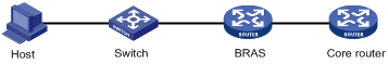
Figure 1 Network diagram for the PPP address pool route
Make sure the destination network of the PPP address pool route includes the PPP address pool. You can execute this command multiple times to configure multiple PPP address pool routes.
Examples
# Configure the PPP address pool route as 2.2.2.2/24.
<Sysname> system-view
[Sysname] ppp ip-pool route 2.2.2.2 24
ppp lcp delay
Use ppp lcp delay to set the LCP negotiation delay timer.
Use undo ppp lcp delay to restore the default.
Syntax
ppp lcp delay milliseconds
undo ppp lcp delay
Default
PPP starts LCP negotiation immediately after the physical layer comes up.
Views
Interface view
Predefined user roles
network-admin
Parameters
milliseconds: Specifies the LCP negotiation delay timer in the range of 1 to 10000 milliseconds.
Usage guidelines
If two ends of a PPP link vary greatly in the LCP negotiation packet processing rate, configure this command on the end with a higher processing rate. The LCP negotiation delay timer prevents frequent LCP negotiation packet retransmission. After the physical layer comes up, PPP starts LCP negotiation when the delay timer expires. If PPP receives LCP negotiation packets before the delay timer expires, it starts LCP negotiation immediately.
Examples
# Set the LCP negotiation delay timer to 130 milliseconds.
<Sysname> system-view
[Sysname] interface virtual-template 1
[Sysname-Virtual-Template1] ppp lcp delay 130
ppp pap local-user
Use ppp pap local-user to set the local username and password for PAP authentication on an interface.
Use undo ppp pap local-user to restore the default.
Syntax
ppp pap local-user username password { cipher | simple } string
undo ppp pap local-user
Default
The local username and password for PAP authentication are blank on an interface.
Views
Interface view
Predefined user roles
network-admin
Parameters
username: Specifies the username of the local device for PAP authentication, a case-sensitive string of 1 to 80 characters.
cipher: Specifies a password in encrypted form.
simple: Specifies a password in plaintext form. For security purposes, the password specified in plaintext form will be stored in encrypted form.
string: Specifies the password. Its plaintext form is a case-sensitive string of 1 to 255 characters. Its encrypted form is a case-sensitive string of 1 to 373 characters.
Usage guidelines
For the local device to pass PAP authentication on the peer, make sure the username and password configured for the local device are also configured on the peer. You can configure the peer's username and password by using the local-user username and password { cipher | simple } string commands, respectively.
Examples
# Set the local username and password for PAP authentication to user1 and plaintext pass1 on Serial 2/1/0.
<Sysname> system-view
[Sysname] interface serial 2/1/0
[Sysname-Serial2/1/0] ppp pap local-user user1 password simple pass1
# Set the local username and password for PAP authentication to user1 and plaintext pass1 on Virtual-Template 1.
<Sysname> system-view
[Sysname] interface virtual-template 1
[Sysname-Virtual-Template1] ppp pap local-user user1 password simple pass1
local-user (Security Command Reference)
password (Security Command Reference)
ppp pfc local-request
Use ppp pfc local-request to configure an interface to send PFC requests by including the PFC option in outbound LCP negotiation requests.
Use undo ppp pfc local to restore the default.
Syntax
ppp pfc local-request
undo ppp pfc local-request
Default
An interface does not include the PFC option in outbound LCP negotiation requests.
Views
Interface view
Predefined user roles
network-admin
Examples
# Configure Serial 2/1/0 to send PFC requests during PPP negotiation.
<Sysname> system-view
[Sysname] interface serial 2/1/0
[Sysname-Serial2/1/0] ppp pfc local-request
# Configure Virtual-Template 1 to send PFC requests during PPP negotiation.
<Sysname> system-view
[Sysname] interface virtual-template 1
[Sysname-Virtual-Template1] ppp pfc local-request
ppp pfc remote-reject
Use ppp pfc remote-reject to configure an interface to reject PFC requests received from the remote peer.
Use undo ppp pfc remote to restore the default.
Syntax
ppp pfc remote-reject
undo ppp pfc remote-reject
Default
An interface accepts PFC requests received from the remote peer, and it performs PFC on frames sent to the peer.
Views
Interface view
Predefined user roles
network-admin
Examples
# Configure Serial 2/1/0 to reject PFC requests received from the remote peer.
<Sysname> system-view
[Sysname] interface serial 2/1/0
[Sysname-Serial2/1/0] ppp pfc remote-reject
# Configure Virtual-Template 1 to reject PFC requests received from the remote peer.
<Sysname> system-view
[Sysname] interface virtual-template 1
[Sysname-Virtual-Template1] ppp pfc remote-reject
ppp timer negotiate
Use ppp timer negotiate to set the PPP negotiation timeout time on an interface.
Use undo ppp timer negotiate to restore the default.
Syntax
ppp timer negotiate seconds
undo ppp timer negotiate
Default
The PPP negotiation timeout time is 3 seconds on an interface.
Views
Interface view
Predefined user roles
network-admin
Parameters
seconds: Specifies the negotiation timeout time in the range of 1 to 10 seconds.
Usage guidelines
In PPP negotiation, if the local device receives no response from the peer during the timeout time after it sends a packet, the local device sends the last packet again.
Examples
# Set the PPP negotiation timeout time to 5 seconds on Serial 2/1/0.
<Sysname> system-view
[Sysname] interface serial 2/1/0
[Sysname-Serial2/1/0] ppp timer negotiate 5
# Set the PPP negotiation timeout time to 5 seconds on Virtual-Template 1.
<Sysname> system-view
[Sysname] interface virtual-template 1
[Sysname-Virtual-Template1] ppp timer negotiate 5
remote address
Use remote address to configure an interface to assign an IP address to the client.
Use undo remote address to restore the default.
Syntax
remote address { ip-address | pool pool-name }
undo remote address
Default
An interface does not assign an IP address to the client.
Views
Interface view
Predefined user roles
network-admin
Parameters
ip-address: Specifies the IP address to be assigned to the client.
pool pool-name: Specifies a PPP or DHCP address pool by its name from which an IP address is assigned to the client. The pool name is a case-sensitive string of 1 to 31 characters.
Usage guidelines
This command can be used when the local interface is configured with an IP address, but the peer has no IP address. To enable the peer to accept the IP address assigned by the local interface (server), you must configure the ip address ppp-negotiate command on the peer to make the peer act as a client.
This command enables the local interface to forcibly assign an IP address to the peer. If the peer is not configured with the ip address ppp-negotiate command but configured with an IP address, the peer will not accept the assigned IP address. This results in an IPCP negotiation failure.
PPP supports IP address assignment from a PPP or DHCP address pool, but the PPP address pool takes precedence over the DHCP address pool. For example, if you use a pool name that identifies both a PPP address pool and a DHCP address pool, the system uses only the PPP address pool for address assignment.
To make the configuration of the remote address command take effect, configure this command before the ip address command, which triggers IPCP negotiation. If you configure the remote address command after the ip address command, the server assigns an IP address to the client during the next IPCP negotiation.
After you use the remote address command to assign an IP address to the client, you can configure the remote address command again or the undo remote address command for the peer. However, the new configuration does not take effect until the next IPCP negotiation.
Examples
# Specify the IP address to be assigned to the client as 10.0.0.1 on Serial 2/1/0.
<Sysname> system-view
[Sysname] interface serial 2/1/0
[Sysname-Serial2/1/0] remote address 10.0.0.1
# Configure Serial 2/1/0 to assign an IP address from address pool aaa to the client.
<Sysname> system-view
[Sysname] interface serial 2/1/0
[Sysname-Serial2/1/0] remote address pool aaa
# Specify the IP address to be assigned to the client as 10.0.0.1 on Virtual-Template 1.
<Sysname> system-view
[Sysname] interface virtual-template 1
[Sysname-Virtual-Template1] remote address 10.0.0.1
# Configure Virtual-Template 1 to assign an IP address from address pool aaa to the client.
<Sysname> system-view
[Sysname] interface virtual-template 1
[Sysname-Virtual-Template1] remote address pool aaa
Related commands
ip address ppp-negotiate
ip pool
remote address dhcp client-identifier
Use remote address dhcp client-identifier username to configure the method of generating DHCP client IDs when PPP users act as DHCP clients.
Use undo remote address dhcp client-identifier to restore the default.
Syntax
remote address dhcp client-identifier { callingnum | username }
undo remote address dhcp client-identifier
Default
The method of generating DHCP client IDs when PPP users act as DHCP clients is not configured.
Views
Interface view
Predefined user roles
network-admin
Parameters
callingnum: Generates DHCP client IDs based on calling numbers. The calling numbers are carried by calling number AVP in L2TP negotiation packets. A calling number contains the MAC address of a user and the VLANs to which the user belongs. For a user with MAC address 000f-e235-dc71 and belonging to outer VLAN 1 and inner VLAN 2, the calling number is 000f-e235-dc71-00010002. If the session-info keyword is also specified, the DHCP client IDs are generated based on the calling numbers and PPP sessions.
username: Generates DHCP client IDs based on the PPP usernames.
Usage guidelines
By default, a PPP client selects a new DHCP client ID each time the PPP client requests an IP address through DHCP. The DHCP server then cannot assign the specific IP addresses to the specific clients according to the client IDs. This command generates DHCP client IDs based on calling numbers or PPP usernames for DHCP pool address assignment.
When DHCP client IDs are generated based on PPP usernames, make sure different users use different PPP usernames to come online.
Examples
# Use the PPP usernames as the DHCP client IDs on Serial 2/1/0 when PPP users act as DHCP clients.
<Sysname> system-view
[Sysname] interface serial 2/1/0
[Sysname-Serial2/1/0] remote address dhcp client-identifier username
# Use the PPP usernames as the DHCP client IDs on Virtual-template 1 when PPP users act as DHCP clients.
<Sysname> system-view
[Sysname] interface virtual-template 1
[Sysname-Virtual-Template1] remote address dhcp client-identifier username
reset ppp access-user
Use reset ppp access-user to log off a PPP user.
Syntax
reset ppp access-user { ip-address ipv4-address [ vpn-instance ipv4-vpn-instance-name ] | ipv6-address ipv6-address [ vpn-instance ipv6-vpn-instance-name ] | username user-name }
Views
User view
Predefined user roles
network-admin
Parameters
ip-address ipv4-address: Specifies a PPP user by its IPv4 address.
ipv6-address ipv6-address: Specifies a PPP user by its IPv6 address.
vpn-instance ipv4-vpn-instance-name: Specifies a PPP user by the VPN to which the user belongs. The ipv4-vpn-instance-name argument specifies the name of the IPv4 MPLS L3VPN instance, a case-sensitive string of 1 to 31 characters. If you do not specify this option, the specified user belongs to the public network.
vpn-instance ipv6-vpn-instance-name: Specifies a PPP user by the VPN to which the user belongs. The ipv6-vpn-instance-name argument specifies the name of the IPv6 MPLS L3VPN instance, a case-sensitive string of 1 to 31 characters. If you do not specify this option, the specified user belongs to the public network.
username user-name: Specifies a PPP user by username, a case-sensitive string of 1 to 80 characters.
Usage guidelines
This command takes effect only on the current login for a PPP user. The user can come online after it is logged off.
Examples
# Log off the PPP user at 192.168.100.2.
<Sysname> reset ppp access-user ip-address 192.168.100.2
Related commands
display ppp access-user
reset ppp compression iphc
Use reset ppp compression iphc to clear IPHC statistics.
Syntax
reset ppp compression iphc [ rtp | tcp ] [ interface interface-type interface-number ]
Views
User view
Predefined user roles
network-admin
Parameters
rtp: Clears IPHC RTP header compression statistics.
tcp: Clears IPHC TCP header compression statistics.
interface interface-type interface-number: Specifies an interface by its type and number. If you do not specify this option, the command clears IPHC statistics on all interfaces.
Usage guidelines
If neither rtp nor tcp is specified, this command clears both RTP header compression and TCP header compression statistics.
Examples
# Clear IPHC statistics on all interfaces.
<Sysname> reset ppp compression iphc
Related commands
display ppp compression iphc
reset ppp packet statistics
Use reset ppp packet statistics to clear PPP negotiation packet statistics.
Syntax
In standalone mode:
reset ppp packet statistics [ slot slot-number ]
In IRF mode:
reset ppp packet statistics [ chassis chassis-number slot slot-number ]
Views
User view
Predefined user roles
network-admin
Parameters
slot slot-number: Specifies a card by its slot number. If you do not specify a card, this command clears PPP negotiation packet statistics for all cards. (In standalone mode.)
chassis chassis-number slot slot-number: Specifies a card on an IRF member device. The chassis-number argument represents the member ID of the IRF member device. The slot-number argument represents the slot number of the card. If you do not specify a card, this command clears PPP negotiation packet statistics for all cards. (In IRF mode.)
Examples
# (In standalone mode.) Clear PPP negotiation packet statistics for slot 2.
<Sysname> reset ppp packet statistics slot 2
# (In IRF mode.) Clear PPP negotiation packet statistics for slot 2 of IRF member device 1.
<Sysname> reset ppp packet statistics chassis 1 slot 2
Related commands
timer-hold
Use timer-hold to set the keepalive interval on an interface.
Use undo timer-hold to restore the default.
Syntax
timer-hold seconds
undo timer-hold
Default
The keepalive interval is 10 seconds on an interface.
Views
Interface view
Predefined user roles
network-admin
Parameters
seconds: Specifies the interval for sending keepalive packets, in the range of 0 to 32767 seconds. The value 0 disables an interface from sending keepalive packets. In this case, the interface can respond to keepalive packets from the peer.
Usage guidelines
An interface sends keepalive packets at keepalive intervals to detect the availability of the peer. If the interface receives no response to keepalive packets when the keepalive retry limit is reached, it determines that the link fails and reports a link layer down event.
To set the keepalive retry limit, use the timer-hold retry command.
On a slow link, increase the keepalive interval to prevent false shutdown of the interface. This situation might occur when keepalive packets are delayed because a large packet is being transmitted on the link.
Examples
# Set the keepalive interval to 20 seconds on Serial 2/1/0.
<Sysname> system-view
[Sysname] interface serial 2/1/0
[Sysname-Serial2/1/0] timer-hold 20
# Set the keepalive interval to 20 seconds on Virtual-Template 1.
<Sysname> system-view
[Sysname] interface virtual-template 1
[Sysname-Virtual-Template1] timer-hold 20
Related commands
timer-hold retry
timer-hold retry
Use timer-hold retry to set the keepalive retry limit on an interface.
Use undo timer-hold retry to restore the default.
Syntax
timer-hold retry retries
undo timer-hold retry
Default
The keepalive retry limit is 5 on an interface.
Views
Interface view
Predefined user roles
network-admin
Parameters
retries: Specifies the maximum number of keepalive attempts in the range of 1 to 255.
Usage guidelines
An interface sends keepalive packets at keepalive intervals to detect the availability of the peer. If the interface receives no response to keepalive packets when the keepalive retry limit is reached, it determines that the link fails and reports a link layer down event.
To set the keepalive interval, use the timer-hold command.
On a slow link, increase the keepalive retry limit to prevent false shutdown of the interface. This situation might occur when keepalive packets are delayed because a large packet is being transmitted on the link.
Examples
# Set the keepalive retry limit to 10 for Serial 2/1/0.
<Sysname> system-view
[Sysname] interface serial 2/1/0
[Sysname-Serial2/1/0] timer-hold retry 10
# Set the keepalive retry limit to 10 for Virtual-Template 1.
<Sysname> system-view
[Sysname] interface virtual-template 1
[Sysname-Virtual-Template1] timer-hold retry 10
Related commands
timer-hold
MP commands
bandwidth
Use bandwidth to set the expected bandwidth of an interface.
Use undo bandwidth to restore the default.
Syntax
bandwidth bandwidth-value
undo bandwidth
Default
The expected bandwidth (in kbps) is the interface baud rate divided by 1000.
Views
VT interface view
MP-group interface view
Predefined user roles
network-admin
Parameters
bandwidth-value: Specifies the expected bandwidth in the range of 1 to 400000000 kbps.
Usage guidelines
The expected bandwidth of an interface affects the link costs in OSPF, OSPFv3, and IS-IS. For more information, see Layer 3—IP Routing Configuration Guide.
Examples
# Set the expected bandwidth of Virtual-Template 10 to 1000 kbps.
<Sysname> system-view
[Sysname] interface virtual-template 10
[Sysname-Virtual-Template10] bandwidth 1000
# Set the expected bandwidth of MP-group 2/0/0 to 1000 kbps.
<Sysname> system-view
[Sysname] interface mp-group 2/0/0
[Sysname-MP-group2/0/0] bandwidth 1000
default
Use default to restore the default settings for a VT or MP-group interface.
Syntax
default
Views
VT interface view
MP-group interface view
Predefined user roles
network-admin
Usage guidelines
|
|
CAUTION: The default command might interrupt ongoing network services. Make sure you are fully aware of the impact of this command before using it on a live network. |
This command might fail to restore the default settings for some commands for reasons such as command dependencies or system restrictions. Use the display this command in interface view to identify these commands. Use the undo forms of these commands or follow the command reference to individually restore their default settings. If your restoration attempt still fails, follow the error message instructions to resolve the problem.
Examples
# Restore the default settings of Virtual-Template 10.
<Sysname> system-view
[Sysname] interface virtual-template 10
[Sysname-Virtual-Template10] default
# Restore the default settings of MP-group 2/0/0.
<Sysname> system-view
[Sysname] interface mp-group 2/0/0
[Sysname-MP-group2/0/0] default
description
Use description to set the description for a VT or MP-group interface.
Use undo description to restore the default.
Syntax
description text
undo description
Default
The description for a VT or MP-group interface is interface name Interface (for example, Virtual-Template1 Interface or MP-group2/0/0 Interface).
Views
VT interface view
MP-group interface view
Predefined user roles
network-admin
Parameters
text: Specifies the interface description, a case-sensitive string of 1 to 255 characters.
Examples
# Set the description for Virtual-Template 10 to virtual-interface.
<Sysname> system-view
[Sysname] interface virtual-template 10
[Sysname-Virtual-Template10] description virtual-interface
# Set the description for MP-group 2/0/0 to mpgroup-interface.
<Sysname> system-view
[Sysname] interface mp-group 2/0/0
[Sysname-MP-group2/0/0] description mpgroup-interface
display interface mp-group
Use display interface mp-group to display information about a specified MP-group interface or all MP-group interfaces.
Syntax
display interface [ mp-group [ interface-number ] ] [ brief [ description | down ] ]
Views
Any view
Predefined user roles
network-admin
network-operator
Parameters
mp-group [ interface-number ]: Specifies an existing MP-group interface by its number. If you do not specify the mp-group keyword, the command displays information about all interfaces except VA interfaces on the device. If you specify the mp-group keyword without the interface-number argument, the command displays information about all existing MP-group interfaces.
brief: Displays brief interface information. If you do not specify this keyword, the command displays detailed interface information.
description: Displays complete interface description. If you do not specify this keyword, the command displays only the first 27 characters of the interface description if the description contains more than 27 characters.
down: Displays information about interfaces in physically down state and the causes. If you do not specify this keyword, the command displays information about all interfaces.
Examples
# Display detailed information about MP-group 2/0/0.
<Sysname> display interface mp-group 2/0/0
MP-group2/0/0
Current state: UP
Line protocol state: UP
Description: MP-group2/0/0 Interface
Bandwidth: 2048kbps
Maximum transmission unit: 1500
Hold timer: 10 seconds,retry times: 5
Internet address: 192.168.1.200/24 (primary)
Link layer protocol: PPP
LCP: opened, MP: opened
Physical: MP, baudrate: 2048000 bps
Output queue - Urgent queuing: Size/Length/Discards 0/100/0
Output queue - Protocol queuing: Size/Length/Discards 0/500/0
Output queue - FIFO queuing: Size/Length/Discards 0/75/0
Last clearing of counters: Never
Last 300 seconds input rate: 0 bytes/sec, 0 packets/sec
Last 300 seconds output rate: 0 bytes/sec, 0 packets/sec
Input: 0 packets, 0 bytes, 0 drops
Output: 0 packets, 0 bytes, 0 drops
# Display brief information about MP-group 2/0/0.
<Sysname> display interface mp-group 2/0/0 brief
Brief information on interfaces in route mode:
Link: ADM - administratively down; Stby - standby
Protocol: (s) - spoofing
Interface Link Protocol Primary IP Description
MP2/0/0 DOWN DOWN --
# Display brief information about the MP-group interfaces in physically down state and the causes.
<Sysname> display interface mp-group brief down
Brief information on interfaces in route mode:
Link: ADM - administratively down; Stby - standby
Interface Link Cause
MP2/0/0 ADM Administratively
MP2/0/1 DOWN Not connected
|
Field |
Description |
|
Current state |
Physical and administrative states of the interface: · DOWN (Administratively)—The interface was administratively shut down with the shutdown command. · DOWN—The interface is administratively up but physically down (possibly because no physical link is present or the link is faulty). · UP—The interface is both administratively and physically up. |
|
Line protocol state |
Data link layer state: UP or DOWN. |
|
Description |
Interface description. |
|
Bandwidth |
Expected bandwidth of the interface. |
|
Hold timer |
Interval at which the interface sends keepalive packets. |
|
retry times |
Keepalive retry limit. The interface determines that its peer has been down if it does not receive a keepalive response when the keepalive retry limit is reached. |
|
Internet protocol processing: Disabled |
The interface cannot process IP packets currently. |
|
Internet address: ip-address/mask-length (Type) |
IP address of the interface and type of the address in parentheses. Possible IP address types include: · Primary—Manually configured primary IP address. · Sub—Manually configured secondary IP address. If the interface has both primary and secondary IP addresses, the primary IP address is displayed. If the interface has only secondary IP addresses, the lowest secondary IP address is displayed. · DHCP-Allocated—DHCP allocated IP address. For more information, see DHCP client configuration in Layer 3—IP Services Configuration Guide. · BOOTP-Allocated—BOOTP allocated IP address. For more information, see BOOTP client configuration in Layer 3—IP Services Configuration Guide. · PPP-Negotiated—IP address assigned by a PPP server during PPP negotiation. For more information, see PPP configuration in Layer 2—WAN Access Configuration Guide. · Unnumbered—IP address borrowed from another interface. · Cellular-Allocated—IP address allocated through the modem-manufacturer's proprietary protocol. For more information, see 3G/4G modem management in Layer 2—WAN Access Configuration Guide. · MAD—IP address assigned to an IRF member device for MAD on the interface. For more information, see IRF configuration in Virtual Technologies Configuration Guide. · MTunnel—IP address of the multicast tunnel interface (MTI), which is the same as the IP address of the MVPN source interface. For more information, see multicast VPN configuration in IP Multicast Configuration Guide. · |
|
LCP: opened, MP: opened |
LCP negotiation is complete. |
|
Physical |
Physical type of the interface. |
|
baudrate |
Baud rate of the interface. |
|
Output queue - Urgent queuing: Size/Length/Discards 0/100/0 Output queue - Protocol queuing: Size/Length/Discards 0/500/0 Output queue - FIFO queuing: Size/Length/Discards 0/75/0 |
Traffic statistics of the interface output queues. |
|
Last clearing of counters: Never |
Last time when statistics on the interface were cleared. Never indicates that statistics on the interface were never cleared. |
|
Last 300 seconds input rate: 0 bytes/sec, 0 packets/sec Last 300 seconds output rate: 0 bytes/sec, 0 packets/sec |
Average rate of input packets and output packets in the last 300 seconds. |
|
Input: 0 packets, 0 bytes, 0 drops |
Total number of inbound packets of the interface (in the number of packets and in bytes), and the number of dropped incoming packets. |
|
Output: 0 packets, 0 bytes, 0 drops |
Total number of outbound packets of the interface (in the number of packets and in bytes), and the number of dropped outgoing packets. |
|
Brief information on interfaces in route mode |
Brief information about Layer 3 interfaces. |
|
Link: ADM - administratively down; Stby - standby |
Link status: · ADM—The interface has been administratively shut down. To recover its physical state, execute the undo shutdown command. · Stby—The interface is operating as a backup interface. To see the primary interface, use the display interface-backup state command in High Availability Command Reference. |
|
Protocol: (s) - spoofing |
Indicates the line protocol is UP, but the physical link is an on-demand link or is not present. |
|
Interface |
Abbreviated interface name. |
|
Link |
Physical link state of the interface: · UP—The interface is physically up. · DOWN—The interface is physically down. · ADM—The interface has been administratively shut down. To recover its physical state, use the undo shutdown command. · Stby—The interface is a backup interface. |
|
Protocol |
Line protocol state: · UP—The line protocol is up. · DOWN—The line protocol is down. · UP(s)—The line protocol is up, but the physical link is an on-demand link or is not present. |
|
Primary IP |
Primary IP address of the interface. |
|
Description |
Interface description configured by using the description command. If you do not specify the description keyword, the display interface brief command displays a maximum of 27 characters of the description. If you specify the description keyword, the command displays the complete description. |
|
Cause |
Causes for the physical state of the interface to be Down: · Not connected—No physical connection exists (possibly because the network cable is disconnected or faulty). · Administratively—The interface was shut down with the shutdown command. To restore the physical state of the interface, use the undo shutdown command. |
Related commands
reset counters interface mp-group
display interface virtual-template
Use display interface virtual-template to display information about VT interfaces.
Syntax
display interface [ virtual-template [ interface-number ] ] [ brief [ description | down ] ]
Views
Any view
Predefined user roles
network-admin
network-operator
Parameters
virtual-template [ interface-number ]: Specifies an existing VT interface by its number. If you do not specify the virtual-template keyword, the command displays information about all interfaces except VA interfaces on the device. If you specify the virtual-template keyword without the interface-number argument, the command displays information about all existing VT interfaces.
brief: Displays brief interface information. If you do not specify this keyword, the command displays detailed interface information.
description: Displays complete interface description. If you do not specify this keyword, the command displays only the first 27 characters of the interface description if the description contains more than 27 characters.
down: Displays information about interfaces in physically down state and the causes. If you do not specify this keyword, the command displays information about all interfaces.
Examples
# Display detailed information about Virtual-Template 1.
<Sysname> display interface virtual-template 1
Virtual-Template1
Current state: DOWN
Line protocol state: DOWN
Description: Virtual-Template1 Interface
Bandwidth: 100000kbps
Maximum transmission unit: 1500
Hold timer: 10 seconds, retry times: 5
Internet address: 192.168.1.200/24 (primary)
Link layer protocol: PPP
LCP: initial
Physical: None, baudrate: 100000000 bps
Output queue - Urgent queuing: Size/Length/Discards 0/100/0
Output queue - Protocol queuing: Size/Length/Discards 0/500/0
Output queue - FIFO queuing: Size/Length/Discards 0/75/0
# Display brief information about Virtual-Template 1.
<Sysname> display interface virtual-template 1 brief
Brief information on interfaces in route mode:
Link: ADM - administratively down; Stby - standby
Protocol: (s) - spoofing
Interface Link Protocol Primary IP Description
VT1 DOWN DOWN --
# Display brief information about the VT interfaces in physically down state and the causes.
<Sysname> display interface Virtual-Template brief down
Brief information on interfaces in route mode:
Link: ADM - administratively down; Stby - standby
Interface Link Cause
VT0 DOWN Not connected
VT12 DOWN Not connected
VT1023 DOWN Not connected
Table 8 Command output
|
Field |
Description |
|
Current state |
Physical state of the interface. This field for a VT interface can only be DOWN. |
|
Line protocol state |
Data link layer state. This field for a VT interface can only be DOWN. |
|
Description |
Interface description. |
|
Bandwidth |
Expected bandwidth of the interface. |
|
Hold timer |
Interval at which the interface sends keepalive packets. |
|
retry times |
Keepalive retry limit. The interface determines that its peer has been down if it does not receive a keepalive response when the keepalive retry limit is reached. |
|
Internet protocol processing: Disabled |
The interface cannot process IP packets currently. |
|
Internet address: ip-address/mask-length (Type) |
IP address of the interface and type of the address in parentheses. Possible IP address types include: · Primary—Manually configured primary IP address. · Sub—Manually configured secondary IP address. If the interface has both primary and secondary IP addresses, the primary IP address is displayed. If the interface has only secondary IP addresses, the lowest secondary IP address is displayed. · DHCP-Allocated—DHCP allocated IP address. For more information, see DHCP client configuration in Layer 3—IP Services Configuration Guide. · BOOTP-Allocated—BOOTP allocated IP address. For more information, see BOOTP client configuration in Layer 3—IP Services Configuration Guide. · PPP-Negotiated—IP address assigned by a PPP server during PPP negotiation. For more information, see PPP configuration in Layer 2—WAN Access Configuration Guide. · Unnumbered—IP address borrowed from another interface. · Cellular-Allocated—IP address allocated through the modem-manufacturer's proprietary protocol. For more information, see 3G/4G modem management in Layer 2—WAN Access Configuration Guide. · MAD—IP address assigned to an IRF member device for MAD on the interface. For more information, see IRF configuration in Virtual Technologies Configuration Guide. · MTunnel—IP address of the multicast tunnel interface (MTI), which is the same as the IP address of the MVPN source interface. For more information, see multicast VPN configuration in IP Multicast Configuration Guide. · |
|
LCP initial |
LCP initialization is complete. |
|
Physical |
Physical type of the interface. |
|
Output queue - Urgent queuing: Size/Length/Discards 0/100/0) Output queue - Protocol queuing: Size/Length/Discards 0/500/0) Output queue - FIFO queuing: Size/Length/Discards 0/75/0) |
Traffic statistics of the interface output queues. |
|
Brief information on interfaces in route mode |
Brief information about Layer 3 interfaces. |
|
Link: ADM - administratively down; Stby - standby |
Link status: · ADM—The interface has been administratively shut down. To recover its physical state, use the undo shutdown command. · Stby—The interface is operating as a backup interface. To see the primary interface, use the display interface-backup state command in High Availability Command Reference. |
|
Protocol: (s) - spoofing |
Indicates the line protocol is UP, but the physical link is an on-demand link or is not present. |
|
Interface |
Abbreviated interface name. |
|
Link |
Physical link state of the interface. This field for a VT interface can only be DOWN. |
|
Protocol |
Line protocol state of the interface. This field for a VT interface can only be DOWN. |
|
Primary IP |
Primary IP address of the interface. |
|
Description |
Interface description configured by using the description command. If you do not specify the description keyword, the display interface brief command displays a maximum of 27 characters of the description. If you specify the description keyword, the command displays the complete description. |
|
Cause |
Causes for the physical state of the interface to be Down. Not connected indicates no physical link exists (possibly because the network cable is disconnected or faulty). |
display ppp mp
Use display ppp mp to display MP information for MP-group interfaces.
Syntax
display ppp mp [ interface interface-type interface-number ]
Any view
Predefined user roles
network-admin
network-operator
Parameters
interface interface-type interface-number: Specifies an interface by its number. If you do not specify this option, the command displays MP information for all interfaces.
Examples
# Display MP information. (MP is configured through an MP-group interface.)
<Sysname> display ppp mp
Template: MP-group2/0/0
max-bind: 20, fragment: enabled, min-fragment: 128
Master link: MP-group2/0/0, Active members: 2, Bundle Multilink
Peer's endPoint descriptor: MP-group2/0/0
Sequence format: short (rcv)/long (sent)
Bundle Up Time: 2012/11/05 07:29:33:612
0 lost fragments, 0 reordered, 0 unassigned, 0 interleaved
Sequence: 0 (rcv)/0 (sent)
Active member channels: 2 members
Serial2/1/0:15 Up-Time: 2012/11/05 07:29:33:613
Serial2/1/0:16 Up-Time: 2012/11/05 07:30:10:945
Inactive member channels: 2 members
Serial2/1/0:17
Serial2/1/0:18
|
Field |
Description |
|
max-bind |
Maximum number of links that can be bound. |
|
fragment |
Indicates whether MP fragmentation is enabled or disabled. |
|
min-fragment |
Minimum size of an MP fragment. |
|
Sequence format: short (rcv)/long (sent) |
Sequence number header format of MP. The short sequence number format is used in the incoming direction, and the long sequence number format is used in the outgoing direction. |
|
reordered |
Number of reassembled packets. |
|
unassigned |
Number of packets waiting for being reassembled. |
|
interleaved |
Number of interleaved fragments. LFI breaks larger packets into fragments and interleaves the fragments between smaller packets for transmission. |
|
Sequence: 0 (rcv)/0 (sent) |
Received sequence number/sent sequence number. |
|
Up-Time |
Uptime of a member channel. |
interface mp-group
Use interface mp-group to create an MP-group interface and enter its view, or enter the view of an existing MP-group interface.
Use undo interface mp-group to remove an MP-group interface.
Syntax
interface mp-group mp-number
undo interface mp-group mp-number
Default
No MP-group interfaces exists.
Views
System view
Predefined user roles
network-admin
Parameters
mp-number: Specifies an MP-group interface by its number. The MP-group interface number is in the range of 0 to 1023.
Usage guidelines
You must use the interface mp-group command together with the ppp mp mp-group command. You can execute the two commands in either order.
Examples
# Create interface MP-group 2/0/0.
<Sysname> system-view
[Sysname] interface mp-group 2/0/0
[Sysname-MP-group2/0/0]
interface virtual-template
Use interface virtual-template to create a VT interface and enter its view, or enter the view of an existing VT interface.
Use undo interface virtual-template to remove a VT interface.
Syntax
interface virtual-template number
undo interface virtual-template number
Default
No VT interfaces exist.
Views
System view
Predefined user roles
network-admin
Parameters
number: Specifies a VT interface by its number. The value range for this argument is 0 to 4095.
Usage guidelines
To remove a VT interface, make sure all the corresponding VA interfaces are removed and the VT interface is not in use.
When you use the configuration replace file command to roll back the configuration, for the interface virtual-template configuration to be successfully rolled back, make sure the following conditions are met:
· All PPPoE users have gone offline.
· All VA pools are deleted.
· VA interfaces are deleted.
Examples
# Create interface Virtual-Template 10.
[Sysname] interface virtual-template 10
[Sysname-Virtual-Template10]
mtu
Use mtu to set the MTU size of an interface.
Use undo mtu to restore the default.
Syntax
mtu size
undo mtu
Default
The MTU size of an interface is 1500 bytes.
Views
VT interface view
MP-group interface view
Predefined user roles
network-admin
Parameters
size: Specifies the MTU size. The value range is 128 to 1650.
Usage guidelines
The MTU size setting of an interface affects the fragmentation and reassembly of IP packets on that interface.
For the configured MTU size to take effect, you must execute the shutdown command and then the undo shutdown command on the interface.
Examples
# Set the MTU size of Virtual-Template 10 to 1400 bytes.
<Sysname> system-view
[Sysname] interface virtual-template 10
[Sysname-Virtual-Template10] mtu 1400
# Set the MTU size of MP-group 2/0/0 to 1200 bytes.
<Sysname> system-view
[Sysname] interface mp-group 2/0/0
[Sysname-MP-group2/0/0] mtu 1200
ppp mp
Use ppp mp to enable MP for an interface.
Use undo ppp mp to disable MP on an interface.
Syntax
ppp mp
undo ppp mp
Default
An interface is enabled with PPP.
Views
Interface view
Predefined user roles
network-admin
Usage guidelines
To obtain more bandwidth, you can bind multiple PPP links to form a logical MP interface.
Examples
# Enable MP for Serial 2/1/0.
<Sysname> system-view
[Sysname] interface serial 2/1/0
[Sysname-Serial2/1/0] ppp mp
# Enable MP for Virtual-Template 1.
<Sysname> system-view
[Sysname] interface virtual-template1
[Sysname-Virtual-Template1] ppp mp
ppp mp binding-mode
Use ppp mp binding-mode to set the MP binding mode on an interface.
Use undo ppp mp binding-mode to restore the default.
Syntax
ppp mp binding-mode { authentication | both | descriptor }
undo ppp mp binding-mode
Default
Both the username and the descriptor are used for MP binding on an interface.
Views
VT interface view
Dialer interface view
Predefined user roles
network-admin
Parameters
authentication: Uses the username for MP binding.
both: Uses both the username and the endpoint descriptor for MP binding.
descriptor: Uses the endpoint descriptor for MP binding.
Usage guidelines
The username is obtained from the peer during PAP, CHAP, MS-CHAP, or MS-CHAP-V2 authentication. The endpoint descriptor, which uniquely identifies a device, is obtained from the peer during LCP negotiation. Based on the username or endpoint descriptor, the system can locate the corresponding VT interface and create an MP bundle according to the template.
The descriptor mode cannot differentiate users. To bind users to different bundles, use the both mode.
The authentication mode cannot differentiate peer devices. When multiple peer devices exist, use the both mode.
Examples
# Specify Virtual-Template 1 to use the username for MP binding.
<Sysname> system-view
[Sysname] interface virtual-template1
[Sysname-Virtual-Template1] ppp mp binding-mode authentication
ppp mp endpoint
Use ppp mp endpoint to set the endpoint option.
Use undo ppp mp endpoint to restore the default.
Syntax
ppp mp endpoint endpoint
undo ppp mp endpoint
Default
The endpoint option carries the device name on an interface.
Views
Interface view
Predefined user roles
network-admin
Parameters
endpoint: Specifies the content of the endpoint option, a case-sensitive string of 1 to 20 characters.
Usage guidelines
The endpoint option (terminal descriptor) is negotiated during MP LCP negotiation.
When MP is configured by using a VT interface, an MP endpoint bases its link binding decisions on the remote endpoint descriptors, and assigns the links that receive the same endpoint descriptor to the same bundle. To avoid incorrect link binding on a VT interface, make sure the link descriptors used by different devices are unique. You must reconfigure an endpoint descriptor for a device if the default endpoint descriptor (device name) cannot uniquely identify the MP bundle at the remote end.
When MP is configured by using an MP-group interface, the negotiating endpoints do not base their binding decisions on the endpoint descriptor. By default, the endpoint descriptor of an interface in an MP-group is the MP-group interface name. If you configure an endpoint descriptor for the interface, the configured MP endpoint descriptor takes effect.
If the endpoint descriptor exceeds 20 bytes, the first 20 bytes are taken as the endpoint descriptor.
Examples
# Configure the endpoint descriptor of Serial 2/1/0 as 123456.
<Sysname> system-view
[Sysname] interface serial 2/1/0
[Sysname-Serial2/1/0] ppp mp endpoint 123456
# Configure the endpoint descriptor of Virtual-Template 1 as 123456.
<Sysname> system-view
[Sysname] interface virtual-template1
[Sysname-Virtual-Template1] ppp mp endpoint 123456
ppp mp fragment disable
Use ppp mp fragment disable to disable MP fragmentation on an interface.
Use undo ppp mp fragment disable to enable MP fragmentation on an interface.
Syntax
ppp mp fragment disable
undo ppp mp fragment disable
Default
MP fragmentation is enabled on an interface.
Views
VT interface view
Dialer interface view
MP-group interface view
Predefined user roles
network-admin
Usage guidelines
If the peer device does not support fragment reassembly, you must configure the ppp mp fragment disable command to disable MP fragmentation on the local device. This enables the two devices to communicate. After that, outgoing packets are not fragmented, but they still carry an MP sequence number and fragment tag.
After you configure the ppp mp fragment disable command on an interface, the settings configured with the ppp mp lfi enable and ppp mp min-fragment commands do not take effect on the interface.
Examples
# Disable MP fragmentation on MP-group 2/0/0.
<Sysname> system-view
[Sysname] interface mp-group 2/0/0
[Sysname-MP-group2/0/0] ppp mp fragment disable
Related commands
ppp mp lfi enable
ppp mp min-fragment
ppp mp lfi delay-per-frag
Use ppp mp lfi delay-per-frag to set the maximum LFI fragment transmission delay on an interface.
Use undo ppp mp lfi delay-per-frag to restore the default.
Syntax
ppp mp lfi delay-per-frag time
undo ppp mp lfi delay-per-frag
Default
The maximum LFI fragment transmission delay is 10 ms on an interface.
Views
VT interface view
Dialer interface view
MP-group interface view
Predefined user roles
network-admin
Parameters
time: Specifies the maximum LFI fragment transmission delay, in the range of 1 to 1000 ms.
Examples
# Set the maximum LFI fragment transmission delay to 20 ms on MP-group 2/0/0.
<Sysname> system-view
[Sysname] interface mp-group 2/0/0
[Sysname-MP-group2/0/0] ppp mp lfi delay-per-frag 20
Related commands
ppp mp lfi enable
ppp mp lfi size-per-frag
ppp mp lfi enable
Use ppp mp lfi enable to enable LFI on an interface.
Use undo ppp mp lfi to disable LFI on an interface.
Syntax
ppp mp lfi enable
undo ppp mp lfi enable
Default
LFI is disabled on an interface.
Views
VT interface view
Dialer interface view
MP-group interface view
Predefined user roles
network-admin
Usage guidelines
Disabling LFI also removes the user-configured settings of the maximum LFI fragment transmission delay and size.
Examples
# Enable LFI on MP-group 2/0/0.
<Sysname> system-view
[Sysname] interface mp-group 2/0/0
[Sysname-MP-group2/0/0] ppp mp lfi enable
ppp mp lfi delay-per-frag
ppp mp lfi size-per-frag
ppp mp lfi size-per-frag
Use ppp mp lfi size-per-frag to set the maximum LFI fragment size (in bytes) on an interface.
Use undo ppp mp lfi size-per-frag to restore the default.
Syntax
ppp mp lfi size-per-frag size
undo ppp mp lfi size-per-frag
Default
On an interface, the maximum LFI fragment size is derived from this formula: (Expected bandwidth of the interface x Maximum LFI fragment transmission delay)/8.
Views
VT interface view
Dialer interface view
MP-group interface view
Predefined user roles
network-admin
Parameters
size: Specifies the maximum LFI fragment size in the range of 40 to 1500 bytes.
Usage guidelines
When LFI is enabled and both this command and the ppp mp lfi delay-per-frag command are configured, the maximum LFI fragment size is the value configured with the ppp mp lfi size-per-frag command.
Examples
# Set the maximum LFI fragment size to 80 bytes on MP-group 2/0/0.
<Sysname> system-view
[Sysname] interface mp-group 2/0/0
[Sysname-MP-group2/0/0] ppp mp lfi size-per-frag 80
Related commands
ppp mp lfi enable
ppp mp lfi delay-per-frag
ppp mp max-bind
Use ppp mp max-bind to set the maximum number of PPP links in an MP bundle on an interface.
Use undo ppp mp max-bind to restore the default.
Syntax
ppp mp max-bind max-bind-num
undo ppp mp max-bind
Default
The maximum number of PPP links in an MP bundle is 16 on an interface.
Views
VT interface view
Dialer interface view
MP-group interface view
Predefined user roles
network-admin
Parameters
max-bind-num: Specifies the maximum number of PPP links in an MP bundle, in the range of 1 to 128.
Usage guidelines
|
|
IMPORTANT: Use the default setting in most situations. Inappropriate use of this command can cause PPP performance degradation. Make sure you understand the impact of this command on your network before you use it. |
Set the maximum number of PPP links in an MP bundle to be greater than the actual number of bound links. Otherwise, MP binding fails.
The maximum number of PPP links configured for an MP bundle takes effect immediately. If the configured maximum number is smaller than the number of existing PPP links, the existing links are not affected.
Examples
# Set the maximum number of PPP links in an MP bundle to 12 on MP-group 2/0/0.
<Sysname> system-view
[Sysname] interface mp-group 2/0/0
[Sysname-MP-group2/0/0] ppp mp max-bind 12
ppp mp min-bind
Use ppp mp min-bind to set the minimum number of PPP links in an MP bundle on a dialer interface.
Use undo ppp mp min-bind to restore the default.
Syntax
ppp mp min-bind min-bind-num
undo ppp mp min-bind
Default
On a dialer interface, the minimum number of PPP links in an MP bundle is 0, which means that MP dial-up relies on traffic detection.
Views
Dialer interface view
Predefined user roles
network-admin
Parameters
min-bind-num: Specifies the minimum number of PPP links in an MP bundle, in the range of 0 to 128.
Usage guidelines
This command specifies the minimum number of PPP links in a MP bundle to ensure the minimum bandwidth for the service.
When the minimum number of PPP links is set to a non-zero value, subsequent MP dial-up operations will not depend on traffic detection, but existing dial-up connections will be removed upon timeout.
The min-bind-num argument cannot be greater than the maximum number set with the ppp mp max-bind command.
Examples
# Set the minimum number of PPP links in an MP bundle to 4 on Dialer 0.
<Sysname> system-view
[Sysname] interface dialer 0
[Sysname-Dialer0] ppp mp min-bind 4
Related commands
ppp mp max-bind
ppp mp min-fragment
Use ppp mp min-fragment to set the minimum MP packet fragmentation size on an interface.
Use undo ppp mp min-fragment to restore the default.
Syntax
ppp mp min-fragment size
undo ppp mp min-fragment
Default
The minimum MP packet fragmentation size is 128 bytes on an interface.
Views
VT interface view
Dialer interface view
MP-group interface view
Predefined user roles
network-admin
Parameters
size: Specifies the minimum MP packet fragmentation size in the range of 128 to 1500 bytes. Outgoing MP packets less than the minimum value will not be fragmented, and those greater than or equal to the minimum value will be fragmented.
Usage guidelines
If MP binding is implemented through hardware (for example, CPOS chip), the minimum MP packet fragmentation size varies with chips. The minimum MP packet fragmentation size on certain chips can only be 128, 256, or 512 bytes. To successfully create the MP bundle and establish the sub-channel LCP link, make sure the setting configured with the ppp mp min-fragment command conforms to the hardware specifications.
Examples
# Set the minimum MP packet fragmentation size to 500 bytes on MP-group 2/0/0.
<Sysname> system-view
[Sysname] interface mp-group 2/0/0
[Sysname-MP-group2/0/0] ppp mp min-fragment 500
ppp mp mp-group
Use ppp mp mp-group to assign an interface to an MP group, and enable MP for the interface.
Use undo ppp mp to restore the default.
Syntax
ppp mp mp-group mp-number
undo ppp mp
Default
An interface is enabled with PPP.
Views
Interface view
Predefined user roles
network-admin
Parameters
mp-number: Specifies an MP-group interface by its number. The MP-group interface number is in the range of 0 to 1023.
Usage guidelines
This command should be used with the interface mp-group command. You can create an MP group interface and then assign an interface to the MP group. You can also assign an interface to an MP group and then create the MP group.
Examples
# Assign Serial 2/1/0 to MP-group 2/0/0.
<Sysname> system-view
[Sysname] interface serial 2/1/0
[Sysname-Serial2/1/0] ppp mp mp-group 2/0/0
Related commands
interface mp-group
ppp mp short-sequence
Use ppp mp short-sequence to trigger MP short sequence number header format negotiation on an interface. After the negotiation succeeds, the local end receives packets with short sequence numbers.
Use undo ppp mp short-sequence to restore the default.
Syntax
ppp mp short-sequence
undo ppp mp short-sequence
Default
The long sequence number header format is used on an interface.
Views
Interface view
Predefined user roles
network-admin
Usage guidelines
This command applies to the incoming direction only. To enable the local end to transmit packets with short sequence numbers, configure this command on the remote end.
The sequence number format (long or short) of an MP bundle depends on the configuration of the first channel joining the MP bundle.
To negotiate the use of short sequence numbers on a dialer MP bundle, configure the command on the dialer interfaces and the ISDN D channels. To negotiate the use of short sequence numbers on a common MP bundle, use the command on all its channels. The command will cause PPP re-negotiation.
Examples
# Configure the short sequence number header format of MP in the incoming direction of Serial 2/1/0.
<Sysname> system-view
[Sysname] interface serial 2/1/0
[Sysname-Serial2/1/0] ppp mp mp-group 2/0/0
[Sysname-Serial2/1/0] ppp mp short-sequence
# Configure the short sequence number header format of MP in the incoming direction of Virtual-Template 1.
<Sysname> system-view
[Sysname] interface virtual-template1
[Sysname-Virtual-Template1] ppp mp short-sequence
ppp mp sort-buffer-size
Use ppp mp sort-buffer-size to set the MP sort buffer size factor on an interface.
Use undo ppp mp sort-buffer-size to restore the default.
Syntax
ppp mp sort-buffer-size size
undo ppp mp sort-buffer-size
Default
The MP sort buffer size factor is 1 on an interface.
Views
VT interface view
Dialer interface view
MP-group interface view
Predefined user roles
network-admin
Parameters
size: Specifies the MP sort buffer size factor in the range of 1 to 64.
Usage guidelines
The MP sort buffer size = the number of channels in the current MP bundle × size. You can use the display ppp mp command to view the number of member channels in an MP bundle. If the calculated MP sort buffer size is 20, the MP sort buffer can sort 20 packets.
When MP is used, the received packets might be out of order. The sort buffer is used to re-sort packets. A large sort buffer results in better re-sorting but increases delay. For voice packets, the transmission delay should be minimized.
Examples
# Set the MP sort buffer size factor to 64 on MP-group 2/0/0.
<Sysname> system-view
[Sysname] interface mp-group 2/0/0
[Sysname-MP-group2/0/0] ppp mp sort-buffer-size 64
ppp mp timer lost-fragment
Use ppp mp timer lost-fragment to set the timer for MP to wait for the expected fragments on an interface.
Use undo ppp mp timer lost-fragment to restore the default.
Syntax
ppp mp timer lost-fragment seconds
undo ppp mp timer lost-fragment
Default
The timer for MP to wait for the expected fragments is 30 seconds on an interface.
Views
VT interface view
Dialer interface view
MP-group interface view
Predefined user roles
network-admin
Parameters
seconds: Specifies the timer for MP to wait for the expected fragment, in the range of 1 to 255 seconds.
Usage guidelines
A receiving end puts the received fragments in the buffer and reassembles them when it receives all the packet's fragments. You can configure a timer for MP to wait for the expected fragments. When the receiving end receives the first fragment of a packet, it starts the timer. When the timer expires, the system checks whether or not all fragments have arrived. If they have all arrived, the system reassembles the fragments. If they have not all arrived, the system discards all received fragments to release the buffer space.
Examples
# Set the timer for MP to wait for the expected fragment to 20 seconds on MP-group 2/0/0.
<Sysname> system-view
[Sysname] interface mp-group 2/0/0
[Sysname-MP-group2/0/0] ppp mp timer lost-fragment 20
ppp mp user
Use ppp mp user to associate a username with a VT interface.
Use undo ppp mp user to remove the association.
Syntax
ppp mp user username bind virtual-template number
undo ppp mp user username
Default
No username is associated with a VT interface.
Views
System view
Predefined user roles
network-admin
Parameters
username: Specifies a username, a case-sensitive string of 1 to 80 characters.
bind virtual-template number: Specifies a VT interface by its number in the range of 0 to 4095.
Usage guidelines
This command associates a username with a VT interface. After the user passes authentication, the system uses the settings on the VT interface to create an MP bundle and a VA interface to transmit data.
You can configure the following parameters for a VT interface:
· Local IP address and the peer IP address (or address pool).
· ppp mp-commands.
Examples
# Associate username user 1 with Virtual-Template 1, and set the IP address of the VT interface to 202.38.60.1/24.
<Sysname> system-view
[Sysname] ppp mp user user1 bind virtual-template 1
[Sysname] interface virtual-template 1
[Sysname-Virtual-Template1] ip address 202.38.60.1 255.255.255.0
Related commands
ppp mp
ppp mp virtual-template
Use ppp mp virtual-template to bind an interface to a VT interface and enable MP for the interface.
Use undo ppp mp to restore the default.
Syntax
ppp mp virtual-template number
undo ppp mp
Default
An interface is enabled with PPP.
Views
Interface view
Predefined user roles
network-admin
Parameters
number: Specifies a VT interface by its number. The value range for this argument is 0 to 4095.
Usage guidelines
After you bind an interface to a VT interface, you can optionally enable PAP, CHAP, MS-CHAP, or MS-CHAP-V2 authentication.
The interfaces bound to the same VT interface are bound together. The ppp mp virtual-template command and the ppp mp command are mutually exclusive.
Examples
# Bind Serial 2/1/0 to Virtual-Template 1, and enable MP for Serial 2/1/0.
<Sysname> system-view
[Sysname] interface serial 2/1/0
[Sysname-Serial2/1/0] ppp mp virtual-template 1
Related commands
ppp mp
reset counters interface mp-group
Use reset counters interface mp-group to clear statistics on MP-group interfaces.
Syntax
reset counters interface [ mp-group [ interface-number ] ]
Views
User view
Predefined user roles
network-admin
Parameters
mp-group: Clears traffic statistics on MP-group interfaces.
interface-number: Specifies an existing MP-group interface by its number.
Usage guidelines
Before collecting traffic statistics regularly on an MP-group interface, clear the existing statistics.
If you do not specify the mp-group keyword, the command clears statistics on all interfaces.
If you specify the mp-group keyword without the interface-number argument, the command clears statistics on all MP-group interfaces.
If you specify both mp-group and interface-number, the command clears statistics on the specified MP-group interface.
Examples
# Clear the statistics of MP-group 2/0/0.
<Sysname> reset counters interface mp-group 2/0/0
Related commands
display interface mp-group
reset counters interface virtual-access
Use reset counters interface virtual-access to clear statistics on VA interfaces.
Syntax
reset counters interface [ virtual-access [ interface-number ] ]
Views
User view
Predefined user roles
network-admin
Parameters
virtual-access: Clears statistics on VA interfaces.
interface-number: Specifies an existing VA interface by its number.
Usage guidelines
Before collecting traffic statistics regularly on a VA interface, clear the existing statistics.
If you do not specify the virtual-access keyword, the command clears statistics on all interfaces.
If you specify the virtual-access keyword without the interface-number argument, the command clears statistics on all VA interfaces.
If you specify both virtual-access and interface-number, the command clears statistics on the specified VA interface.
Examples
# Clear statistics on Virtual-Access 10.
<Sysname> reset counters interface virtual-access 10
Related commands
display interface virtual-access
service
Use service to specify a primary traffic processing slot for an interface.
Use undo service to restore the default.
In standalone mode:
service slot slot-number
undo service slot
In IRF mode:
service chassis chassis-number slot slot-number
undo service chassis
Default
No primary traffic processing slot is specified for an interface.
Views
VT interface view
Predefined user roles
network-admin
Parameters
slot slot-number: Specifies a card by its slot number. (In standalone mode.)
chassis chassis-number slot slot-number: Specifies a card on an IRF member device. The chassis-number argument represents the member ID of the IRF member device. The slot-number argument represents the slot number of the card. (In IRF mode.)
Usage guidelines
Specify traffic processing slots if a feature requires that all traffic on an VA interface be processed on the same slot.
For high availability, you can specify one primary and one backup traffic processing slot by using the service command and the service standby command, respectively.
To avoid processing slot switchover, specify the primary slot before specifying the backup slot. If you specify the backup slot before specifying the primary slot, traffic is switched over to the primary slot immediately after you specify the primary slot.
If you specify both primary and backup slots for an interface, traffic on that interface is processed as follows:
· The backup slot takes over when the primary slot becomes unavailable. The backup slot continues to process traffic for the interface after the primary slot becomes available again. The switchover will not occur until the backup slot becomes unavailable.
· When no specified traffic processing slots are available, the traffic is processed on the slot at which it arrives. Then, the processing slot that first becomes available again takes over.
If you do not specify a primary or a backup traffic processing slot for an interface, traffic on that interface is processed on the slot at which the traffic arrives.
Examples
# (In standalone mode.) Specify slot 2 as the primary traffic processing slot for the VA interfaces on Virtual-Template 10.
<Sysname> system-view
[Sysname] interface virtual-template 10
[Sysname-Virtual-Template10] service slot 2
# (In IRF mode.) Specify slot 2 on IRF member device 2 as the primary traffic processing slot for the VA interfaces on Virtual-Template 10.
<Sysname> system-view
[Sysname] interface virtual-template 10
[Sysname-Virtual-Template10] service chassis 2 slot 2
service standby
service standby
Use service standby to specify a backup traffic processing slot for an interface.
Use undo service standby to restore the default.
Syntax
In standalone mode:
service standby slot slot-number
undo service standby slot
In IRF mode:
service standby chassis chassis-number slot slot-number
undo service standby chassis
Default
No backup traffic processing slot is specified for an interface.
Views
VT interface view
Predefined user roles
network-admin
Parameters
slot slot-number: Specifies a card by its slot number. (In standalone mode.)
chassis chassis-number slot slot-number: Specifies a card on an IRF member device. The chassis-number argument represents the member ID of the IRF member device. The slot-number argument represents the slot number of the card. (In IRF mode.)
Usage guidelines
Specify traffic processing slots if a feature requires that all traffic on an VA interface be processed on the same slot.
For high availability, you can specify one primary and one backup traffic processing slot by using the service command and the service standby command, respectively.
To avoid processing slot switchover, specify the primary slot before specifying the backup slot. If you specify the backup slot before specifying the primary slot, traffic is switched over to the primary slot immediately after you specify the primary slot.
If you specify both primary and backup slots for an interface, traffic on that interface is processed as follows:
· The backup slot takes over when the primary slot becomes unavailable. The backup slot continues to process traffic for the interface after the primary slot becomes available again. The switchover will not occur until the backup slot becomes unavailable.
· When no specified traffic processing slots are available, the traffic is processed on the slot at which it arrives. Then, the processing slot that first becomes available again takes over.
If you do not specify a primary or a backup traffic processing slot for an interface, traffic on that interface is processed on the slot at which the traffic arrives.
Examples
# (In standalone mode.) Specify slot 2 as the primary traffic processing slot for the VA interfaces on Virtual-Template 10. Specify slot 3 as the backup traffic processing slot for the VA interfaces on Virtual-Template 10.
<Sysname> system-view
[Sysname] interface virtual-template 10
[Sysname-Virtual-Template10] service slot 2
[Sysname-Virtual-Template10] service standby slot 3
# (In IRF mode.) Specify slot 2 on IRF member device 2 as the primary traffic processing slot for the VA interfaces on Virtual-Template 10. Specify slot 3 on IRF member device 2 as the backup traffic processing slot for the VA interfaces on Virtual-Template 10.
<Sysname> system-view
[Sysname] interface virtual-template 10
[Sysname-Virtual-Template10] service chassis 2 slot 2
[Sysname-Virtual-Template10] service standby chassis 2 slot 3
Related commands
service
shutdown
Use shutdown to shut down an MP-group interface.
Use undo shutdown to bring up an MP-group interface.
Syntax
shutdown
undo shutdown
Default
An MP-group interface is up.
Views
MP-group interface view
Predefined user roles
network-admin
Examples
# Shut down MP-group 2/0/0.
<Sysname> system-view
[Sysname] interface mp-group 2/0/0
[Sysname-MP-group2/0/0] shutdown
PPPoE commands
PPPoE server commands
display pppoe-server packet statistics
Use display pppoe-server packet statistics to display PPPoE server negotiation packet statistics.
Syntax
In standalone mode:
display pppoe-server packet statistics [ slot slot-number ]
In IRF mode:
display pppoe-server packet statistics [ chassis chassis-number slot slot-number ]
Views
Any view
Predefined user roles
network-admin
network-operator
Parameters
slot slot-number: Specifies a card by its slot number. If you do not specify a card, this command displays PPPoE server negotiation packet statistics for all cards. (In standalone mode.)
chassis chassis-number slot slot-number: Specifies a card on an IRF member device. The chassis-number argument represents the member ID of the IRF member device. The slot-number argument represents the slot number of the card. If you do not specify a card, this command displays PPPoE server negotiation packet statistics for all cards. (In IRF mode.)
Examples
# (In standalone mode.) Display PPPoE server negotiation packet statistics for slot 2.
<Sysname> display pppoe-server packet statistics slot 2
PPPoE Server packet statistics in slot 2:
RECV_PADI_PKT : 10 DISCARD_PADI_PKT : 0
SEND_PADO_PKT : 10
RECV_PADR_PKT : 10 DISCARD_PADR_PKT : 0
SEND_PADS_PKT : 10
RECV_PADT_PKT : 9 DISCARD_PADT_PKT : 0
SEND_PADT_PKT : 9
# (In IRF mode.) Display PPPoE server negotiation packet statistics for IRF member device 1 in slot 2.
<Sysname> display pppoe-server packet statistics chassis 1 slot 2
PPPoE Server packet statistics in chassis 1 slot 2:
RECV_PADI_PKT : 834826 DISCARD_PADI_PKT : 1277
SEND_PADO_PKT : 833471
RECV_PADR_PKT : 833357 DISCARD_PADR_PKT : 0
SEND_PADS_PKT : 833357
RECV_PADT_PKT : 833253 DISCARD_PADT_PKT : 0
SEND_PADT_PKT : 295671
Table 10 Command output
|
Field |
Description |
|
RECV_PADI_PKT |
Number of received PADI packets. |
|
DISCARD_PADI_PKT |
Number of discarded PADI packets. |
|
SEND_PADO_PKT |
Number of sent PADO packets. |
|
RECV_PADR_PKT |
Number of received PADR packets. |
|
DISCARD_PADR_PKT |
Number of discarded PADR packets. |
|
SEND_PADS_PKT |
Number of sent PADS packets. |
|
RECV_PADT_PKT |
Number of received PADT packets. |
|
DISCARD_PADT_PKT |
Number of discarded PADT packets. |
|
SEND_PADT_PKT |
Number of sent PADT packets. |
Related commands
reset pppoe-server packet statistics
display pppoe-server session packet
Use display pppoe-server session packet to display packet statistics for PPPoE sessions.
Syntax
In standalone mode:
display pppoe-server session packet { slot slot-number | interface interface-type interface-number }
In IRF mode:
display pppoe-server session packet { chassis chassis-number slot slot-number | interface interface-type interface-number }
Views
Predefined user roles
network-admin
network-operator
Parameters
interface interface-type interface-number: Specifies an interface by its type and number.
slot slot-number: Specifies a card by its slot number. If you do not specify a card, the command displays packet statistics for PPPoE sessions on all cards. (In standalone mode.)
chassis chassis-number slot slot-number: Specifies a card on an IRF member device. The chassis-number argument represents the member ID of the IRF member device. The slot-number argument represents the slot number of the card. If you do not specify a card, the command displays packet statistics for PPPoE sessions on all cards. (In IRF mode.)
Examples
# Display packet statistics for PPPoE sessions on GigabitEthernet 1/0/1.
<Sysname> display pppoe-server session packet interface gigabitethernet 1/0/1
Total PPPoE sessions: 2
Ethernet interface: GE1/0/1 Session ID: 1
InPackets: 37 OutPackets: 38
InBytes: 390 OutBytes: 406
InDrops: 0 OutDrops: 0
Ethernet interface: GE1/0/1 Session ID: 2
InPackets: 67 OutPackets: 48
InBytes: 490 OutBytes: 806
InDrops: 1 OutDrops: 2
Table 11 Command output
|
Field |
Description |
|
Ethernet interface |
Interface where the PPPoE session is present. |
|
Session ID |
PPPoE session ID. |
|
InPackets |
Number of packets received. |
|
OutPackets |
Number of packets transmitted. |
|
InBytes |
Number of bytes received. |
|
OutBytes |
Number of bytes transmitted. |
|
InDrops |
Number of discarded incoming packets. |
|
OutDrops |
Number of discarded outgoing packets. |
Related commands
display interface virtual-access
display pppoe-server session summary
Use display pppoe-server session summary to display summary PPPoE session information.
Syntax
In standalone mode:
display pppoe-server session summary { slot slot-number | interface interface-type interface-number }
In IRF mode:
display pppoe-server session summary { chassis chassis-number slot slot-number | interface interface-type interface-number }
Views
Any view
Predefined user roles
network-admin
network-operator
Parameters
interface interface-type interface-number: Specifies an interface by its type and number.
slot slot-number: Specifies a card by its slot number. If you do not specify a card, the command displays summary PPPoE session information for all cards. (In standalone mode.)
chassis chassis-number slot slot-number: Specifies a card on an IRF member device. The chassis-number argument represents the member ID of the IRF member device. The slot-number argument represents the slot number of the card. If you do not specify a card, the command displays summary PPPoE session information for all cards. (In IRF mode.)
Usage guidelines
Summary PPPoE session information on a physical interface can be displayed only on the card where the interface resides. Summary PPPoE session information on a logical interface can be displayed on all cards.
Examples
# Display summary PPPoE session information on GigabitEthernet 1/0/1.
<Sysname> display pppoe-server session summary interface gigabitethernet 1/0/1
Total PPPoE sessions: 2
Ethernet interface: GE1/0/1 Session ID: 1
PPP interface: VA1 State: PADR_RCVD
Remote MAC: 00e0-1500-7100 Local MAC: 00e0-1400-7300
Service VLAN: N/A Customer VLAN: N/A
Ethernet interface: GE1/0/1 Session ID: 2
PPP interface: VA2 State: OPEN
Remote MAC:00e0-1600-7200 Local MAC: 00e0-1400-7400
Service VLAN: 2 Customer VLAN: 155
# (In standalone mode.) Display summary PPPoE session information on slot 2.
<Sysname> display pppoe-server session summary slot 2
Total PPPoE sessions on slot 2: 2
Local PPPoE sessions on slot 2: 1
Ethernet interface: GE2/0/2 Session ID: 1
PPP interface: VA1 State: OPEN
Remote MAC: 0000-0000-0005 Local MAC: 0000-5e00-0101
Service VLAN: N/A Customer VLAN: N/A
Ethernet interface: RAGG1 Session ID: 1
PPP interface: VA0 State: OPEN
Remote MAC: 0050-56c0-0005 Local MAC: 0000-5e00-0102
Service VLAN: N/A Customer VLAN: N/A
Table 12 Command output
|
Field |
Description |
|
Total PPPoE sessions |
Total number of PPPoE sessions on physical interfaces and logical interfaces. |
|
Local PPPoE sessions |
Total number of PPPoE sessions on physical interfaces. When an interface is specified, this field is not displayed. |
|
Ethernet interface |
Interface where the PPPoE session is present. |
|
Session ID |
PPPoE session ID. |
|
PPP interface |
Virtual access interface created for the PPPoE session. |
|
State |
PPPoE session state: · PADR RCVD—The PPPoE session is being negotiated. · Open—The PPPoE session has been successfully established. |
|
RemoteMAC |
MAC address of the remote end. |
|
LocalMAC |
MAC address of the local end. |
|
Service VLAN |
Service provider VLAN. N/A means no service provider VLAN is available. |
|
Customer VLAN |
Customer VLAN. N/A means no customer VLAN is available. |
display pppoe-server throttled-mac
Use display pppoe-server throttled-mac to display information about blocked users.
Syntax
In standalone mode:
display pppoe-server throttled-mac { slot slot-number | interface interface-type interface-number }
In IRF mode:
display pppoe-server throttled-mac { chassis chassis-number slot slot-number | interface interface-type interface-number }
Views
Any view
Predefined user roles
network-admin
network-operator
Parameters
interface interface-type interface-number: Specifies an interface by its type and number.
slot slot-number: Specifies a card by its slot number. If you do not specify a card, the command displays information about blocked users on all cards. (In standalone mode.)
chassis chassis-number slot slot-number: Specifies a card on an IRF member device. The chassis-number argument represents the member ID of the IRF member device. The slot-number argument represents the slot number of the card. If you do not specify a card, the command displays information about blocked users on all cards. (In IRF mode.)
Examples
# Display information about blocked users on GigabitEthernet 1/0/1.
<Sysname> display pppoe-server throttled-mac interface gigabitethernet 1/0/1
Total 3 client MACs:
Interface Remote MAC Start time Remaining time(s)
GE1/0/1 00e0-1500-4100 2010-12-01,12:10:30 55
GE1/0/1 00e0-1500-4000 2010-12-01,12:10:40 65
GE1/0/1 00e0-1500-3300 2010-12-01,12:10:50 75
Table 13 Command output
|
Field |
Description |
|
Interface |
Interface at which the user is blocked. |
|
Remote MAC |
MAC address of the user. |
|
Start time |
Time to start blocking users. |
|
Remaining time(s) |
Time left for blocking users, in seconds. |
Related commands
pppoe-server throttle per-mac
display pppoe-server va-pool
Use display pppoe-server va-pool to display information about VA pools.
Syntax
display pppoe-server va-pool
Views
Any view
Predefined user roles
network-admin
network-operator
Examples
# (In standalone mode.) Display information about VA pools.
<Sysname> display pppoe-server va-pool
Location VT interface Size Unused/State
Virtual-Template1 1000 900
0/cpu1 Virtual-Template2 1000 1000
Table 14 Command output
|
Field |
Description |
|
Location |
IRF member device, card, and CPU where the VA pool resides. When the field displays a hyphen (-), it indicates a global VA pool. If the device cannot display the CPU, an asterisks (*) is displayed, for example, 1/0/*. |
|
VT interface |
Virtual-Template interface that uses the VA pool. |
|
Unused/State |
VA pool capacity available for PPP users/current state of the VA pool. · Creating—The VA pool is being created. · Destroying—The VA pool is being removed. |
Related commands
pppoe-server virtual-template va-pool
ppp lcp echo mru verify
Use ppp lcp echo mru verify to enable maximum receive unit (MRU) verification for PPPoE on a VT interface.
Use undo ppp lcp echo mru verify to disable MRU verification for PPPoE.
Syntax
ppp lcp echo mru verify [minimum value ]
undo ppp lcp echo mru verify
Default
MRU verification for PPPoE is disabled on a VT interface.
Views
VT interface view
Predefined user roles
network-admin
Parameters
minimum value: Specifies the minimum MRU in the range of 64 to 1500 bytes.
Usage guidelines
To support an MTU larger than 1492, PPPoE adds the PPP-Max-Payload option during PPPoE negotiation. This option identifies the MTU for the current PPPoE session. If the MTU is larger than 1492, PPP uses the MTU as the MRU during LCP negotiation, and reports the MTU after negotiation.
MRU verification prevents the negotiated MRU from exceeding the receiving and sending capabilities of the interface. If the negotiated MRU is larger than 1492, the PPPoE server sends an echo request that has the same size as the negotiated MRU. If the PPPoE server receives a reply, it uses the MRU as the MTU. If the PPPoE server fails to receive a reply, the following situations occur:
· If the minimum MRU is configured, the PPPoE server sends a packet that has the same size as the minimum MRU.
· If the minimum MRU is not configured, the PPPoE server sends a packet that has the same size as the negotiated MRU.
If the second verification still fails, the PPPoE server tears down the link.
NCP negotiation starts after the MRU verification succeeds.
Examples
# Enable MRU verification for PPPoE and set the minimum MRU to 1200 bytes on Virtual-Template 10.
<Sysname> system-view
[Sysname] interface virtual-template 10
[Sysname-Virtual-Template10] ppp lcp echo mru verify minimum 1200
pppoe-server access-delay
Use pppoe-server access-delay to set the response delay time on an interface.
Use undo pppoe-server access-delay to restore the default.
Syntax
pppoe-server access-delay delay-time
undo pppoe-server access-delay
Default
No response delay time is set on an interface.
Views
Layer 3 Ethernet interface/subinterface view
VEth interface/subinterface view
VLAN interface view
Layer 3 aggregate interface/subinterface view
L3VE interface/subinterface view
EFM interface/subinterface view
Predefined user roles
network-admin
Parameters
delay-time: Specifies the response delay time, in the range of 10 to 25500 milliseconds.
Usage guidelines
The system responds to the first packet of a PPP connection on the interface after the configured delay time elapses.
Examples
# Set the response delay time to 100 milliseconds on GigabitEthernet 1/0/1.
<Sysname> system-view
[Sysname] interface gigabitethernet 1/0/1
[Sysname-GigabitEthernet1/0/1] pppoe-server access-delay 100
pppoe-server access-line-id bas-info
Use pppoe-server access-line-id bas-info to configure the NAS-Port-ID attribute to automatically include BAS information on an interface.
Use undo pppoe-server access-line-id bas-info to restore the default.
Syntax
pppoe-server access-line-id bas-info [ cn-163 ]
undo pppoe-server access-line-id bas-info
Default
The NAS-Port-ID attribute does not automatically include BAS information on an interface.
Views
Layer 3 Ethernet interface/subinterface view
VEth interface/subinterface view
VLAN interface view
Layer 3 aggregate interface/subinterface view
L3VE interface/subinterface view
EFM interface/subinterface view
Predefined user roles
network-admin
Parameters
cn-163: Specifies the China Telecom 163 format for the BAS information. If you do not specify this keyword, BAS information in the China Telecom format is included.
Usage guidelines
The bas-info formats include China Telecom and China Telecom 163.
The China Telecom format is {atm|eth|trunk} NAS_slot/NAS_subslot/NAS_port:XPI.XCI. The format refers to the user access interface information on the BAS device, including upstream interface, VLAN, and VPI/VCI information:
· When ATM/DSL is used, XPI.XCI refers to VPI/VCI information.
· When Ethernet/DSL is used, XPI.XCI refers to VLAN information.
For example, eth 1/0/1:4096.2345 includes the following user access interface information:
· The type of the upstream interface is Ethernet interface.
· The interface is located at slot 1, subslot 0, and port 1.
· The outer VLAN ID is 4096 (which means an invalid VLAN), and the inner VLAN ID is 2345.
Table 15 shows the China Telecom 163 format, where:
· NAS_slot, NAS_subslot, and NAS_port refer to the numbering information of the PPPoE user access interface on the BAS device.
· vpi and vci refer to VPI and VCI information.
· vlanid and vlanid2 refer to inner VLAN and outer VLAN, respectively. The value for the vlanid of the primary interface is fixed at 0.
Table 15 BAS information in China Telecom 163 format
|
Interface type |
Format |
|
ATM interface |
slot=NAS_slot;subslot=NAS_subslot;port=NAS_port;vpi=XPI;vci=XCI; |
|
Primary interface or interface that does not carry inner VLAN or outer VLAN information. |
slot=NAS_slot;subslot=NAS_subslot;port=NAS_port;vlanid=VLAN id; |
|
Interface that carries inner VLAN and outer VLAN information. |
slot=NAS_slot;subslot=NAS_subslot;port=NAS_port;vlanid=VLAN id;vlanid2=VLAN id2; |
This command determines the content of the NAS-Port-ID attribute that the PPPoE server delivers to the RADIUS server.
· If the cn-163 keyword is specified, the PPPoE server automatically inserts the corresponding BAS information before the parsed circuit-id. Then it sends the combination of the bas-info and circuit-id as the NAS-Port-ID attribute to the RADIUS server.
· If the cn-163 keyword is not specified, the PPPoE server creates a new circuit-id in China Telecom format. Then it sends the new circuit-id as the NAS-Port-ID attribute to the RADIUS server. The new circuit-id contains the corresponding BAS information and the DSLAM user access information in the original circuit-id.
If this command is not executed, the NAS-Port-ID attribute that the PPPoE server delivers to the RADIUS server is determined by the pppoe-server access-line-id content command.
The RADIUS server cannot correctly parse a NAS-Port-ID attribute that includes the remote-id and BAS information. When you configure this command together with the pppoe-server access-line-id trust command, make sure the NAS-Port-ID attribute sent to the RADIUS sever does not include the remote-id.
Examples
# Configure the NAS-Port-ID attribute to automatically include BAS information on GigabitEthernet 1/0/1.
<Sysname> system-view
[Sysname] interface gigabitethernet 1/0/1
[Sysname-GigabitEthernet1/0/1] pppoe-server access-line-id bas-info
Related commands
pppoe-server access-line-id circuit-id parse-mode
pppoe-server access-line-id content
pppoe-server access-line-id trust
pppoe-server access-line-id circuit-id parse-mode
Use pppoe-server access-line-id circuit-id parse-mode to configure the format that an interface uses to parse the circuit-id in the access line ID.
Use undo pppoe-server access-line-id circuit-id parse-mode to restore the default.
Syntax
pppoe-server access-line-id circuit-id parse-mode { cn-telecom | tr-101 }
undo pppoe-server access-line-id circuit-id parse-mode
Default
An interface uses the TR-101 format to parse the circuit-id.
Views
Layer 3 Ethernet interface/subinterface view
VEth interface/subinterface view
VLAN interface view
Layer 3 aggregate interface/subinterface view
L3VE interface/subinterface view
EFM interface/subinterface view
Predefined user roles
network-admin
Parameters
cn-telecom: Specifies China Telecom format.
tr-101: Specifies TR-101 format.
Usage guidelines
The circuit-id formats include TR-101 and China Telecom.
The TR-101 format is Access-Node-Identifier atm slot/port:vpi.vci for ATM/DSL, and is Access-Node-Identifier eth slot/port[:vlan-id] for Ethernet/DSL. The entire ID refers to the user access information on the DSLAM, where
· Access-Node-Identifier refers to the identifier of the DSLAM.
· The remainder refers to information about the user access interface on the DSLAM.
The China Telecom format is AccessNodeIdentifier/ANI_rack/ANI_frame/ANI_slot/ANI_subslot/ANI_port[:ANI_XPI.ANI_XCI]. The format refers to user access information on the DSLAM, including DSLAM identifier and user access interface.
For example, the circuit-id guangzhou001/1/31/63/31/127 includes the following information:
· The identifier of the access node DSLAM is guangzhou001.
· The rack number of the DSLAM is 1.
· The user access interface is located at port 127, subslot 31, slot 63, and frame 31.
Examples
# Configure GigabitEthernet 1/0/1 to use China Telecom format to parse the circuit-id.
<Sysname> system-view
[Sysname] interface gigabitethernet 1/0/1
[Sysname-GigabitEthernet1/0/1] pppoe-server access-line-id circuit-id parse-mode cn-telecom
Related commands
pppoe-server access-line-id circuit-id trans-format
pppoe-server access-line-id circuit-id trans-format
Use pppoe-server access-line-id circuit-id trans-format to configure the transmission format for the circuit-id in access line ID on an interface.
Use undo pppoe-server access-line-id circuit-id trans-format to restore the default.
Syntax
pppoe-server access-line-id circuit-id trans-format { ascii | hex }
undo pppoe-server access-line-id circuit-id trans-format
Default
The transmission format for the circuit-id in access line ID is a string of characters on an interface.
Views
Layer 3 Ethernet interface/subinterface view
VEth interface/subinterface view
VLAN interface view
Layer 3 aggregate interface/subinterface view
L3VE interface/subinterface view
EFM interface/subinterface view
Predefined user roles
network-admin
Parameters
ascii: Specifies the character string format. For example, the circuit-id 00010002 is transmitted in the form of 01 08 30 30 30 31 30 30 30 32.
hex: Specifies the hexadecimal format. For example, the circuit-id 00010002 is transmitted in the form of 01 04 00 01 00 02.
Examples
# Configure GigabitEthernet 1/0/1 to use the hexadecimal format to transmit the circuit-id.
<Sysname> system-view
[Sysname] interface gigabitethernet 1/0/1
[Sysname-GigabitEthernet1/0/1] pppoe-server access-line-id circuit-id trans-format hex
pppoe-server access-line-id content
Use pppoe-server access-line-id content to configure the content of the NAS-Port-ID attribute delivered to the RADIUS server on an interface.
Use undo pppoe-server access-line-id content to restore the default.
Syntax
pppoe-server access-line-id content { all [ separator ] | circuit-id | remote-id }
undo pppoe-server access-line-id content
Default
The NAS-Port-ID attribute contains only the circuit-id on an interface.
Views
Layer 3 Ethernet interface/subinterface view
VEth interface/subinterface view
VLAN interface view
Layer 3 aggregate interface/subinterface view
L3VE interface/subinterface view
EFM interface/subinterface view
Predefined user roles
network-admin
Parameters
all: Sends both the circuit-id and remote-id.
separator: Specifies a separator that is one character long. By default, the value is a blank space. The circuit-id and remote-id are connected by the separator.
circuit-id: Sends only the circuit-id.
remote-id: Sends only the remote-id.
Usage guidelines
The PPPoE server on a BAS device uses the RADIUS NAS-Port-ID attribute to send the access line ID received from a DSLAM device to the RADIUS server. The access line ID contains the circuit-id and remote-id. The RADIUS server compares the received NAS-Port-ID attribute with the local line ID information to verify the location of the user.
For more information about the circuit-id, see the pppoe-server access-line-id circuit-id parse-mode command.
For more information about the remote-id, see pppoe-server access-line-id remote-id trans-format the command.
Do not use a character that exists in the circuit-id or remote-id as the separator. Otherwise, the RADIUS server might fail to parse the ID information.
This command determines the content of the NAS-Port-ID attribute only when the pppoe-server access-line-id bas-info command is not configured. Otherwise, the pppoe-server access-line-id bas-info command determines the content of the NAS-Port-ID attribute.
Examples
# Configure GigabitEthernet 1/0/1 to deliver only the circuit-id to the RADIUS server.
<Sysname> system-view
[Sysname] interface gigabitethernet 1/0/1
[Sysname-GigabitEthernet1/0/1] pppoe-server access-line-id content circuit-id
Related commands
pppoe-server access-line-id bas-info
pppoe-server access-line-id circuit-id parse-mode
pppoe-server access-line-id remote-id trans-format
pppoe-server access-line-id remote-id trans-format
Use pppoe-server access-line-id remote-id trans-format to configure the transmission format for the remote-id in the access line ID on an interface.
Use undo pppoe-server access-line-id remote-id trans-format to restore the default.
Syntax
pppoe-server access-line-id remote-id trans-format { ascii | hex }
undo pppoe-server access-line-id remote-id trans-format
Default
The transmission format for the remote-id is a string of characters on an interface.
Views
Layer 3 Ethernet interface/subinterface view
VEth interface/subinterface view
VLAN interface view
Layer 3 aggregate interface/subinterface view
L3VE interface/subinterface view
EFM interface/subinterface view
Predefined user roles
network-admin
Parameters
ascii: Specifies the character string format.
hex: Specifies the hexadecimal format.
Usage guidelines
The remote-id is the system MAC address of a PPPoE relay device (for example, DSLAM). It can be transmitted in character strings or hexadecimal format.
Examples
# Configure GigabitEthernet 1/0/1 to use the hexadecimal format to transmit the remote-id.
<Sysname> system-view
[Sysname] interface gigabitethernet 1/0/1
[Sysname-GigabitEthernet1/0/1] pppoe-server access-line-id remote-id trans-format hex
pppoe-server access-line-id trust
Use pppoe-server access-line-id trust to configure the PPPoE server to trust the access line ID in received packets on an interface.
Use undo pppoe-server access-line-id trust to restore the default.
Syntax
pppoe-server access-line-id trust
undo pppoe-server access-line-id trust
Default
The PPPoE server does not trust the access line ID in received packets on an interface.
Views
Layer 3 Ethernet interface/subinterface view
VEth interface/subinterface view
VLAN interface view
Layer 3 aggregate interface/subinterface view
L3VE interface/subinterface view
EFM interface/subinterface view
Predefined user roles
network-admin
Usage guidelines
This command enables the PPPoE server to parse the circuit-id and remote-id in a received packet, and creates a new circuit-id and remote-id. If the PPPoE server fails to parse the circuit-id or remote-id in a PADR packet, it discards the packet and does not return a PADS packet.
If this command is not executed, the PPPoE server does not parse the circuit-id and remote-id in a received packet. The contents of both the new circuit-id and the remote-id are null.
Examples
# Configure GigabitEthernet 1/0/1 to trust the access line ID in received packets.
<Sysname> system-view
[Sysname] interface gigabitethernet 1/0/1
[Sysname-GigabitEthernet1/0/1] pppoe-server access-line-id trust
Related commands
pppoe-server access-line-id circuit-id parse-mode
pppoe-server bind
Use pppoe-server bind to enable the PPPoE server on an interface and bind the interface to a VT interface.
Use undo pppoe-server bind to disable the PPPoE server on an interface.
Syntax
pppoe-server bind virtual-template number
undo pppoe-server bind
Default
The PPPoE server is disabled on an interface.
Views
Layer 3 Ethernet interface/subinterface view
VEth interface/subinterface view
VLAN interface view
Layer 3 aggregate interface/subinterface view
L3VE interface/subinterface view
EFM interface/subinterface view
Predefined user roles
network-admin
Parameters
virtual template number: Specifies a VT interface by its number. The value range for the number argument is 0 to 4095.
Usage guidelines
A PPPoE server-enabled interface can be bound to a nonexistent VT interface.
If the interface has been bound to a VT interface, you cannot use this command to bind the interface to another VT interface. To do that, disable the PPPoE server on the interface first.
If both the PPPoE client and PPPoE server are enabled on an interface, the PPPoE client feature does not take effect.
Examples
# Enable the PPPoE server on GigabitEthernet 1/0/1 and bind the interface to Virtual-Template 1.
<Sysname> system-view
[Sysname] interface gigabitethernet 1/0/1
[Sysname-GigabitEthernet1/0/1] pppoe-server bind virtual-template 1
pppoe-server session-limit
Use pppoe-server session-limit to set the maximum number of PPPoE sessions on an interface.
Use undo pppoe-server session-limit to restore the default.
Syntax
pppoe-server session-limit number
undo pppoe-server session-limit
Default
The number of PPPoE sessions on an interface is not limited.
Views
Layer 3 Ethernet interface/subinterface view
VEth interface/subinterface view
VLAN interface view
Layer 3 aggregate interface/subinterface view
L3VE interface/subinterface view
EFM interface/subinterface view
Predefined user roles
network-admin
Parameters
number: Specifies the maximum number of PPPoE sessions on an interface, in the range of 1 to 65534.
Usage guidelines
PPPoE can establish a session when none of the following limits are reached:
· Limit for a user on an interface.
· Limit for a VLAN on an interface.
· Limit on an interface.
· Limit on a card.
New maximum number settings only apply to subsequently established PPPoE sessions.
Examples
# Set the maximum number of PPPoE sessions on GigabitEthernet 1/0/1 to 50.
<Sysname> system-view
[Sysname] interface gigabitethernet 1/0/1
[Sysname-GigabitEthernet1/0/1] pppoe-server session-limit 50
Related commands
pppoe-server session-limit per-mac
pppoe-server session-limit per-vlan
pppoe-server session-limit total
pppoe-server session-limit per-mac
Use pppoe-server session-limit per-mac to set the maximum number of PPPoE sessions for a user on an interface.
Use undo pppoe-server session-limit per-mac to restore the default.
Syntax
pppoe-server session-limit per-mac number
undo pppoe-server session-limit per-mac
Default
A user can create a maximum of 100 PPPoE sessions on an interface.
Views
Layer 3 Ethernet interface/subinterface view
VEth interface/subinterface view
VLAN interface view
Layer 3 aggregate interface/subinterface view
L3VE interface/subinterface view
EFM interface/subinterface view
Predefined user roles
network-admin
Parameters
number: Specifies the maximum number of PPPoE sessions for a user, in the range of 1 to 65534.
Usage guidelines
A user is identified by a MAC address.
PPPoE can establish a session when none of the following limits are reached:
· Limit for a user on an interface.
· Limit for a VLAN on an interface.
· Limit on an interface.
· Limit on a card.
New maximum number settings only apply to subsequently established PPPoE sessions.
Examples
# Set the maximum number of PPPoE sessions for a user on GigabitEthernet 1/0/1 to 50.
<Sysname> system-view
[Sysname] interface gigabitethernet 1/0/1
[Sysname-GigabitEthernet1/0/1] pppoe-server session-limit per-mac 50
Related commands
pppoe-server session-limit
pppoe-server session-limit per-vlan
pppoe-server session-limit total
pppoe-server session-limit per-vlan
Use pppoe-server session-limit per-vlan to set the maximum number of PPPoE sessions for a VLAN on an interface.
Use undo pppoe-server session-limit per-vlan to restore the default.
Syntax
pppoe-server session-limit per-vlan number
undo pppoe-server session-limit per-vlan
Default
The number of PPPoE sessions for a VLAN on an interface is not limited.
Views
Layer 3 Ethernet subinterface view
VEth subinterface view
Layer 3 aggregate subinterface view
L3VE subinterface view
EFM subinterface view
Predefined user roles
network-admin
Parameters
number: Specifies the maximum number of PPPoE sessions for a VLAN, in the range of 1 to 65534.
Usage guidelines
PPPoE can establish a session when none of the following limits are reached:
· Limit for a user on an interface.
· Limit for a VLAN on an interface.
· Limit on an interface.
· Limit on a card.
New maximum number settings only apply to subsequently established PPPoE sessions.
Examples
# Set the maximum number of PPPoE sessions for a VLAN on GigabitEthernet 1/0/1.1 to 50.
<Sysname> system-view
[Sysname] interface gigabitethernet 1/0/1.1
[Sysname-GigabitEthernet1/0/1.1] pppoe-server session-limit per-vlan 50
Related commands
pppoe-server sessions limit
pppoe-server sessions limit per-mac
pppoe-server sessions limit total
pppoe-server session-limit total
Use pppoe-server session-limit total to set the maximum number of PPPoE sessions on a card.
Use undo pppoe-server session-limit total to restore the default.
Syntax
In standalone mode:
pppoe-server session-limit slot slot-number total number
undo pppoe-server session-limit slot slot-number total
In IRF mode:
pppoe-server session-limit chassis chassis-number slot slot-number total number
undo pppoe-server session-limit chassis chassis-number slot slot-number total
Default
The number of PPPoE sessions on a card is not limited.
Views
System view
Predefined user roles
network-admin
Parameters
number: Specifies the maximum number of PPPoE sessions on a device, in the range of 1 to 65534.
slot slot-number: Specifies a card by its slot number. (In standalone mode.)
chassis chassis-number slot slot-number: Specifies a card on an IRF member device. The chassis-number argument represents the member ID of the IRF member device. The slot-number argument represents the slot number of the card. (In IRF mode.)
Usage guidelines
PPPoE can establish a session when none of the following limits are reached:
· Limit for a user on an interface.
· Limit for a VLAN on an interface.
· Limit on an interface.
· Limit on a card.
The maximum number of PPPoE sessions on a card is also limited by the device specification. If the configured number is larger than the device specification, the device specification applies.
New maximum number settings only apply to subsequently established PPPoE sessions.
Examples
# (In standalone mode.) Set the maximum number of PPPoE sessions for slot 2 to 3000.
<Sysname> system-view
[Sysname] pppoe-server session-limit slot 2 total 3000
# (In IRF mode.) Set the maximum number of PPPoE sessions on card 2 of IRF member device 1 to 3000.
<Sysname> system-view
[Sysname] pppoe-server session-limit chassis 1 slot 2 total 3000
Related commands
pppoe-server session-limit
pppoe-server session-limit per-mac
pppoe-server session-limit per-vlan
pppoe-server tag ac-name
Use pppoe-server tag ac-name to set the access concentrator (AC) name for the PPPoE server on an interface.
Use undo pppoe-server tag ac-name to restore the default.
Syntax
pppoe-server tag ac-name name
undo pppoe-server tag ac-name
Default
The AC name for the PPPoE server is the device name on an interface.
Views
Layer 3 Ethernet interface/subinterface view
VEth interface/subinterface view
VLAN interface view
Layer 3 aggregate interface/subinterface view
L3VE interface/subinterface view
EFM interface/subinterface view
Predefined user roles
network-admin
Parameters
name: Specifies an AC name, a case-sensitive string of 1 to 64 characters.
Usage guidelines
The PPPoE server sends its AC name in PADO packets. PPPoE clients choose a PPPoE server by AC name. The PPPoE clients on H3C devices cannot identify PPPoE servers by AC name.
The device does not support an AC name comprised of all blank spaces.
Examples
# Specify the AC name for the PPPoE server on GigabitEthernet 1/0/1 as pppoes.
<Sysname> system-view
[Sysname] interface gigabitethernet 1/0/1
[Sysname-GigabitEthernet1/0/1] pppoe-server tag ac-name pppoes
pppoe-server tag ppp-max-payload
Use pppoe-server tag ppp-max-payload to enable the PPPoE server to support the ppp-max-payload tag and set a range for the tag on an interface.
Use undo pppoe-server tag ppp-max-payload to restore the default.
Syntax
pppoe-server tag ppp-max-payload [ minimum min-number maximum max-number ]
undo pppoe-server tag ppp-max-payload
Default
The PPPoE server does not support ppp-max-payload tag on an interface. The PPPoE server ignores the ppp-max-payload tag in PADI or PADS packets from clients, and returns a PADO or PADS packets without the ppp-max-payload tag.
Views
Layer 3 Ethernet interface/subinterface view
VEth interface/subinterface view
VLAN interface view
Layer 3 aggregate interface/subinterface view
L3VE interface/subinterface view
EFM interface/subinterface view
Predefined user roles
network-admin
Parameters
minimum min-number: Specifies the minimum value for the PPP maximum payload, in the range of 64 to 4470 bytes. The default value is 1492 bytes.
maximum max-number: Specifies the maximum value for the PPP maximum payload, in the range of 64 to 4470 bytes. The default value is 1500 bytes. The max-number argument must be equal or greater than the min-number argument.
Usage guidelines
This command enables the PPPoE server to forward large PPP packets with a payload larger than 1492 bytes and reduces fragmentation. If the ppp-max-payload tag sent by the PPPoE client is within the tag range, the PPPoE server returns a PADO or PADS packet that includes the tag. If not, the PPPoE server considers the received packets invalid, and it does not return a PADO or PADS packet.
The jumboframe enable command can change the size of jumbo frames supported by the interface. The maximum size of the jumbo frames configured by the jumboframe enable command should be larger than the maximum value configured by the pppoe-server tag ppp-max-payload command.
Examples
# Enable the PPPoE server to support the ppp-max-payload tag and set the value for the PPP maximum payload to be in the range of 1494 to 1580 bytes on GigabitEthernet 1/0/1.
<Sysname> system-view
[Sysname] interface gigabitethernet 1/0/1
[Sysname-GigabitEthernet1/0/1] pppoe-server tag ppp-max-payload minimum 1494 maximum 1508
Related commands
jumboframe enable (Interface Command References)
pppoe-server tag service-name
Use pppoe-server tag service-name to set a service name for a PPPoE server on an interface.
Use undo pppoe-server tag service-name to restore the default.
Syntax
pppoe-server tag service-name name
undo pppoe-server tag service-name
Default
A PPPoE server does not have a service name.
Views
Layer 3 Ethernet interface/subinterface view
VEth interface/subinterface view
VLAN interface view
Layer 3 aggregate interface/subinterface view
L3VE interface/subinterface view
EFM interface/subinterface view
Predefined user roles
network-admin
Parameters
name: Specifies a service name, a case-sensitive string of 1 to 64 characters.
Usage guidelines
Service names identify the traffic destined for PPPoE servers when multiple PPPoE servers are providing services on the network. A PPPoE client establishes a session with the target PPPoE server by using the following process:
1. The client broadcasts a PADI packet.
2. The server compares its service name with the service-name tag field of the PADI packet. The server sends a PADO packet to the client if either of the following conditions exists:
¡ The field matches the service name.
¡ No service name is configured.
3. The client sends a PADR packet to the server.
4. The server compares its service name with the service-name tag field of the PADR packet. The server sends a PADS packet and sets up a session with the client if either of the following conditions exists:
¡ The field matches the service name.
¡ No service name is configured.
Examples
# Set the service name to pppoes for the PPPoE server on GigabitEthernet 1/0/1.
<Sysname> system-view
[Sysname] interface gigabitethernet 1/0/1
[Sysname-GigabitEthernet1/0/1] pppoe-server tag service-name pppoes
pppoe-server throttle per-mac
Use pppoe-server throttle per-mac to set the PPPoE access limit on an interface.
Use undo pppoe-server throttle per-mac to restore the default.
Syntax
pppoe-server throttle per-mac session-requests session-request-period blocking-period
undo pppoe-server throttle per-mac
Default
The PPPoE access rate is not limited on an interface.
Views
Layer 3 Ethernet interface/subinterface view
VEth interface/subinterface view
VLAN interface view
Layer 3 aggregate interface/subinterface view
L3VE interface/subinterface view
EFM interface/subinterface view
Predefined user roles
network-admin
Parameters
session-requests: Specifies the maximum number of PPPoE session requests from a user within the monitoring time. The value range is 1 to 100000.
session-request-period: Specifies the monitoring time in the range of 1 to 3600 seconds.
blocking-period: Specifies the blocking time in the range of 1 to 3600 seconds.
Usage guidelines
This command limits the rate at which a user (identified by MAC address) can create PPPoE sessions on an interface. If the number of PPPoE requests within the monitoring time exceeds the configured threshold, the device discards the excessive requests, and outputs log messages. If the blocking time is set to 0, the device does not block any requests, and it only outputs log messages.
The device uses a monitoring table and a blocking table to control PPP access rates.
· Monitoring table—Stores a maximum of 8000 monitoring entries. Each entry records the number of PPPoE sessions created by a user within the monitoring time. When the monitoring entries reach the maximum, the system stops monitoring and blocking session requests from new users. The aging time of monitoring entries is determined by the session-request-period argument. When the timer expires, the system starts a new round of monitoring for the user.
· Blocking table—Stores a maximum of 8000 blocking entries. The system creates a blocking entry if the access rate of a user reaches the threshold, and blocks requests from that user. When the blocking entries reach the maximum, the system stops blocking session requests from new users and it only outputs log messages. The aging time of the blocking entries is determined by the blocking-period argument. When the timer expires, the system starts a new round of monitoring for the user.
If the access rate setting is changed, the system removes all monitoring and blocking entries, and uses the new settings to limit PPPoE access rates.
Examples
# Limit the rate at which a user can create PPPoE sessions on GigabitEthernet 1/0/1.
<Sysname> system-view
[Sysname] interface gigabitethernet 1/0/1
[Sysname-GigabitEthernet1/0/1] pppoe-server throttle per-mac 100 100 5
Related commands
display pppoe-server throttled-mac
pppoe-server virtual-template va-pool
Use pppoe-server virtual-template va-pool to configure a VA pool.
Use undo pppoe-server virtual-template va-pool to remove a VA pool.
Syntax
In standalone mode:
pppoe-server virtual-template template-number [ slot slot-number ] va-pool va-volume
undo pppoe-server virtual-template template-number [ slot slot-number ] va-pool
In IRF mode:
pppoe-server virtual-template template-number [ chassis chassis-number slot slot-number ] va-pool va-volume
undo pppoe-server virtual-template template-number [ chassis chassis-number slot slot-number ] va-pool
Default
No VA pool is configured.
Views
System view
Predefined user roles
network-admin
Parameters
virtual-template template-number: Specifies an existing VT interface to use the VA pool.
va-pool va-volume: Specifies the maximum number of VA interfaces contained in the VA pool, in the range of 1 to 65534.
slot slot-number: Specifies a card by its slot number. If you do not specify a card, a global VA pool is created. (In standalone mode.)
chassis chassis-number slot slot-number: Specifies a card of an IRF member device. The chassis-number argument represents the member ID of the IRF member device. The slot-number argument represents the slot number of the card. If you do not specify a card, a global VA pool is created. (In IRF mode.)
Usage guidelines
The PPPoE server creates a VA interface for a PPPoE session to transmit packets between PPPoE and PPP, and removes the VA interface when the user goes offline. Creating and removing VA interfaces take time.
You can configure VA pools to improve the performance of PPPoE session establishment and termination. A VA pool contains a group of automatically numbered VA interfaces. The PPPoE server selects a VA interface from the pool for a requesting user and release the VA interface when the user goes offline. When a VA pool is exhausted, the system creates VA interfaces for new PPPoE sessions, and removes those VA interfaces when the users go offline.
On a VT interface, you can create one global VA pool and one regional VA pool per member device for interfaces bound with the VT interface.
· The global VA pool contains VA interfaces for logical interfaces that might span multiple devices, such as Ethernet aggregate interfaces.
· The regional VA pool contains VA interfaces for interfaces that do not span multiple devices, such as Ethernet interfaces.
When you configure a VA pool, follow these guidelines:
· To change the capacity of a VA pool, you must delete the previous configuration, and reconfigure the VA pool.
· Creating or removing a VA pool takes time. During the process of creating or removing a VA pool, users can go online or offline, but the VA pool does not take effect.
· If the system fails to create a VA pool because of insufficient resources, you can view the available resources by using the display pppoe-server va-pool command.
· VA pools are memory intensive. Set their capacity depending on your network requirements.
· Deleting a VA pool does not log off the users who are using VA interfaces in the VA pool.
Examples
# Create a VA pool with a capacity of 1000 VA interfaces on Virtual-Template 2.
<Sysname> system-view
[Sysname] pppoe-server virtual-template 2 va-pool 1000
Related commands
display pppoe-server va-pool
reset pppoe-server
Use reset pppoe-server to clear PPPoE sessions on the PPPoE server.
Syntax
reset pppoe-server { all | interface interface-type interface-number | virtual-template number }
Views
User view
Predefined user roles
network-admin
Parameters
all: Clears all PPPoE sessions.
interface interface-type interface-number: Specifies an interface by its type and number.
virtual-template number: Specifies a VT interface by its number.
Examples
# Clear established sessions on Virtual-template 1 on the PPPoE server.
<Sysname> reset pppoe-server virtual-template 1
reset pppoe-server packet statistics
Use reset pppoe-server packet statistics to clear PPPoE server negotiation packet statistics.
Syntax
In standalone mode:
reset pppoe-server packet statistics [ slot slot-number ]
In IRF mode:
reset pppoe-server packet statistics [ chassis chassis-number slot slot-number ]
Views
Any view
Predefined user roles
network-admin
Parameters
slot slot-number: Specifies a card by its slot number. If you do not specify a card, this command clears PPPoE server negotiation packet statistics for all cards. (In standalone mode.)
chassis chassis-number slot slot-number: Specifies a card on an IRF member device. The chassis-number argument represents the member ID of the IRF member device. The slot-number argument represents the slot number of the card. If you do not specify a card, this command clears PPPoE server negotiation packet statistics for all cards. (In IRF mode.)
Examples
# (In standalone mode.) Clear PPPoE server negotiation packet statistics for slot 2.
<Sysname> reset pppoe-server packet statistics slot 2
# (In IRF mode.) Clear PPPoE server negotiation packet statistics for slot 2 of IRF member device 1.
<Sysname> reset pppoe-server packet statistics chassis 1 slot 2
Related commands
display pppoe-server packet statistics
PPPoE client commands
dialer diagnose
Use dialer diagnose to configure DDR to operate in diagnostic mode.
Use undo dialer diagnose to restore the default.
Syntax
dialer diagnose [ interval interval ]
undo dialer diagnose
Default
DDR operates in non-diagnostic mode.
Views
Dialer interface view
Predefined user roles
network-admin
Parameters
interval: Specifies the diagnostic interval in the range of 5 to 65535 seconds. The default is 120 seconds.
Usage guidelines
This command takes effect only when a dialer interface is used with PPPoE client applications.
In diagnostic mode, the device performs the following operations:
· Dials a PPPoE connection immediately after the device configurations are complete.
· Automatically terminates the connection.
· Starts the auto-dial timer after a configurable diagnostic interval.
· Redials a connection when the auto-dial timer expires.
By establishing and terminating PPPoE sessions periodically, you can monitor the operating status of the PPPoE link.
In diagnostic mode, the link idle-timeout timer is ignored.
Examples
# Configure Dialer 1 to operate in diagnostic mode, with a diagnostic interval of 300 seconds.
<Sysname> system-view
[Sysname] interface dialer 1
[Sysname-Dialer1] dialer diagnose interval 300
Related commands
dialer timer autodial
dialer timer idle
display pppoe-client session packet
Use display pppoe-client session packet to display the protocol packet statistics for a PPPoE session.
Syntax
display pppoe-client session packet [ dial-bundle-number number ]
Views
Any view
Predefined user roles
network-admin
network-operator
Parameters
dial-bundle-number number: Specifies the dialer bundle number corresponding to a PPPoE session. The value range for the number argument is 0 to 1023. If you do not specify this option, the command displays the protocol packet statistics for all PPPoE sessions.
Usage guidelines
To display the data packet statistics for a PPPoE session, use the display interface virtual-access command to display information about the specified VA interface.
Examples
# Display the protocol packet statistics for all PPPoE sessions.
<Sysname> display pppoe-client session packet
Bundle: 1 Interface: GE1/0/1
InPackets: 19 OutPackets: 19
InBytes: 816 OutBytes: 816
InDrops: 0 OutDrops: 0
Bundle: 2 Interface: GE1/0/1
InPackets: 18 OutPackets: 18
InBytes: 730 OutBytes: 730
InDrops: 0 OutDrops: 0
Table 16 Command output
|
Field |
Description |
|
Bundle |
Dialer bundle to which a PPPoE session belongs. |
|
Interface |
Ethernet interface where the PPPoE session is present. |
|
InPackets |
Number of packets received. |
|
OutPackets |
Number of packets transmitted. |
|
InBytes |
Number of bytes received. |
|
OutBytes |
Number of bytes transmitted. |
|
InDrops |
Number of discarded incoming packets. |
|
OutDrops |
Number of discarded outgoing packets. |
Related commands
display interface virtual-access
reset pppoe-client session packet
display pppoe-client session summary
Use display pppoe-client session summary to display summary PPPoE session information.
Syntax
display pppoe-client session summary [ dial-bundle-number number ]
Views
Any view
Predefined user roles
network-admin
network-operator
Parameters
dial-bundle-number number: Specifies the dialer bundle number corresponding to a PPPoE session. The value range for the number argument is 0 to 1023. If you do not specify this option, the command displays summary information for all PPPoE sessions.
Examples
# Display summary information for all PPPoE sessions.
<Sysname> display pppoe-client session summary
Bundle ID Interface VA RemoteMAC LocalMAC State
1 1 GE1/0/1 VA0 00e0-1400-4300 00e0-1500-4100 SESSION
2 1 GE1/0/2 VA1 00e0-1500-4300 00e0-1600-4100 SESSION
Table 17 Command output
|
Field |
Description |
|
Bundle |
Dialer bundle to which the PPPoE session belongs. |
|
Interface |
Ethernet interface where the PPPoE session is present. |
|
VA |
Virtual access interface created for the PPPoE session. |
|
RemoteMAC |
MAC address of the remote end. |
|
LocalMAC |
MAC address of the local end. |
|
State |
PPPoE session state: · IDLE—Initialization state. · PADI SENT—A PPPoE Active Discovery Initiation (PADI) packet has been sent, and a PPPoE Active Discovery Offer (PADO) packet is being expected. · PADR SENT—A PPPoE Active Discovery Request (PADR) packet has been sent, and a PPPoE Active Discovery Session-confirmation (PADS) packet is being expected. · SESSION—The PPPoE session has been successfully established. |
pppoe-client
Use pppoe-client to establish a PPPoE session and specify the dialer bundle corresponding to the session.
Use undo pppoe-client to remove a PPPoE session.
Syntax
pppoe-client dial-bundle-number number [ no-hostuniq ]
undo pppoe-client dial-bundle-number number
Default
No PPPoE session is established.
Views
Layer 3 Ethernet interface/subinterface view
VEth interface/subinterface view
VLAN interface view
Layer 3 aggregate interface/subinterface view
Predefined user roles
network-admin
Parameters
dial-bundle-number number: Specifies the dialer bundle number corresponding to a PPPoE session. A dialer bundle number uniquely identifies a PPPoE session. It can also be used as a PPPoE session ID. The value range for this argument is 0 to 1023.
no-hostuniq: Configures the client not to carry the Host-Uniq field in discovery packets. If you do not specify this keyword, the client carries the Host-Unique field. The Host-Unique field uniquely identifies a PPPoE client when an interface is configured with multiple PPPoE sessions. When the PPPoE server receives a packet with this field, it must include this field unmodified in the response packet. The device identifies the PPPoE client where the response packet belongs based on the Host-Unique field in the response packet.
Examples
# Establish a PPPoE session on GigabitEthernet 1/0/1.
<Sysname> system-view
[Sysname] interface gigabitethernet 1/0/1
[Sysname-GigabitEthernet1/0/1] pppoe-client dial-bundle-number 1
# Establish a PPPoE session on Virtual-Ethernet 0.
<Sysname> system-view
[Sysname] interface virtual-ethernet 0
[Sysname-Virtual-Ethernet0] pppoe-client dial-bundle-number 1
# Establish a PPPoE session on VLAN-Interface 1.
<Sysname> system-view
[Sysname] interface vlan-interface 1
[Sysname-Vlan-interface1] pppoe-client dial-bundle-number 1
reset pppoe-client
Use reset pppoe-client to reset a PPPoE session corresponding to a dialer bundle.
Syntax
reset pppoe-client { all | dial-bundle-number number }
Views
User view
Predefined user roles
network-admin
Parameters
all: Resets all the PPPoE sessions.
dial-bundle-number number: Specifies a dialer bundle by its number. The value range for this argument is 0 to 1023.
Usage guidelines
A PPPoE session in permanent mode and terminated by this command will be established again when the auto dial timer expires.
A PPPoE session in on-demand mode and terminated by this command will be established again only when there is a need for data transmission.
Examples
# Reset all PPPoE sessions.
<Sysname> reset pppoe-client all
Related commands
dialer timer autodial
reset pppoe-client session packet
Use reset pppoe-client session packet to reset the protocol packet statistics for a PPPoE session.
Syntax
reset pppoe-client session packet [ dial-bundle-number number ]
Views
User view
Predefined user roles
network-admin
Parameters
dial-bundle-number number: Specifies the dialer bundle number corresponding to a PPPoE session. The value range for this argument is 0 to 1023. If you do not specify this option, the command resets the protocol packet statistics for all PPPoE sessions.
Examples
# Reset the protocol packet statistics for all PPPoE sessions.
<Sysname> reset pppoe-client session packet
Related commands
display pppoe-client session packet