- Table of Contents
- Related Documents
-
| Title | Size | Download |
|---|---|---|
| 01-Text | 6.23 MB |
Command and hardware compatibility
Configuring CAPWAP tunnel establishment
Setting the AP connection priority for the AC
Enabling the AC to respond to only unicast discovery requests
Enabling an AP to prefer discovering ACs by IPv6 address
Configuring AC rediscovery in AP view
Configuring AC rediscovery in AP group view
Configuring AC rediscovery in global configuration view
Configuring the mapping between a software version and a hardware version of an AP model
Specifying the preferred location for the AC to obtain an AP image file
Configuring CAPWAP tunnel latency detection
Setting the control tunnel keepalive time for an AP
Setting the data tunnel keepalive time for an AP
Setting the maximum fragment size for CAPWAP packets
Setting the TCP MSS for CAPWAP tunnels
Configuring AC request retransmission
Configuring AC request retransmission in AP view
Configuring AC request retransmission in AP group view
Setting the statistics report interval
Setting the statistics report interval in AP view
Setting the statistics report interval in AP group view
Configuring remote AP in AP view
Configuring remote AP in AP group view
Configuring the default input power level
Configuration restrictions and guidelines
Configuring the default input power level in AP view
Configuring the default input power level in AP group's AP model view
Enabling or disabling USB interfaces for APs
Enabling or disabling USB interfaces in AP view
Enabling or disabling USB interfaces in AP group' AP model view
Managing the file system of an AP
Configuration restrictions and guidelines
Configuring preprovisioned settings for an AP
Configuring network settings for an AP group
Assigning preprovisioned settings to APs
Configuring auto loading of preprovisioned settings
Configuration restrictions and guidelines
Enabling service anomaly detection
Displaying and maintaining AP management
Displaying AP management information
Clearing AP management information
AP management configuration examples
CAPWAP tunnel establishment through DHCP configuration example
CAPWAP tunnel establishment through DHCPv6 configuration example
CAPWAP tunnel establishment through DNS configuration example
AP group configuration example
Configuration restrictions and guidelines
Enabling or disabling all radios
Enabling or disabling a radio in radio view
Enabling or disabling a radio in AP group radio view
Configuring basic radio functions
Configuring 2.4 GHz radios to use the European channel gap for auto channel selection
Configuring the channel selection blacklist or whitelist
Setting the maximum transmit power
Setting the maximum transmission distance
Setting the maximum number of clients that can associate with an AP
Configuring 802.11b client access
Specifying a collision avoidance mode
Configuring 802.11g protection
Setting the fragmentation threshold
Setting the maximum number of hardware retransmissions
Performing on-demand channel usage measurement
Enabling the continuous mode for a radio
Specifying the A-MPDU aggregation method
Specifying the A-MSDU aggregation method
Configuring access for only 802.11n and 802.11ac clients
Setting the 802.11n bandwidth mode
Configuring 802.11n protection
Configuring 802.11ac functions
Configuring access for only 802.11ac clients
Setting the 802.11ac bandwidth mode
Configuring the smart antenna feature
Displaying and maintaining radio management
Radio management configuration examples
Basic radio function configuration example
Whitelist- and blacklist-based access control
Configuration restrictions and guidelines
Configuring a service template
Configuring a description for a service template
Specifying the VLAN allocation method for clients
Configuring clients to prefer the authorization VLAN after roaming
Setting the client cache aging time
Enabling client association at the AC or APs
Specifying the client traffic forwarder
Enabling client traffic forwarding
Setting the encapsulation format for client data frames
Binding a service template to a radio·
Binding a service template to a radio in radio view
Binding a service template to a radio in AP group radio view
Specifying a region code in AP view
Specifying a region code in AP group view
Specifying a global region code
Disabling an AP from responding to broadcast probe requests
Disabling an AP from responding to broadcast probe requests in AP view
Disabling APs in an AP group from responding to broadcast probe requests in AP group view
Setting the client idle timeout timer
Setting the client idle timeout timer in AP view
Setting the client idle timeout timer in AP group view
Configuring client keepalive in AP view··
Configuring client keepalive in AP group view
Configuring an AP to not inherit the specified service template from an AP group
Setting the NAS ID in AP group view
Setting the way in which an AP processes traffic from unknown clients
Configuring policy-based forwarding
Configuring a forwarding policy
Applying a forwarding policy to a service template
Applying a forwarding policy to a user profile
Specifying a permitted AP group for client access
Specifying a permitted SSID for client access
Adding a client to the whitelist
Adding a client to the static blacklist
Configuring the dynamic blacklist
Setting the idle period before client reauthentication
Deploying a configuration file to an AP
Deploying a configuration file to an AP in AP view
Deploying a configuration file to an AP in AP group AP model view
Configuring uplink client rate limit
Specifying the Web server to which client information is reported
Enabling the device to generate client logs in the specified format
Displaying and maintaining WLAN access
WLAN access configuration examples
WLAN access configuration example
Whitelist configuration example
Static blacklist configuration example
WLAN security configuration task lists
Setting the security information element
Setting the TKIP MIC failure hold time
Configuring management frame protection
Enabling the dynamic WEP mechanism
Enabling SNMP notifications for WLAN security
Displaying and maintaining WLAN security
WLAN security configuration examples
Shared key authentication configuration example
PSK authentication and bypass authentication configuration example
PSK authentication and MAC authentication configuration example
802.1X AKM configuration example
Management frame protection configuration example
Dynamic WEP mechanism configuration example
Private PSK authentication and MAC authentication configuration example
802.1X authentication initiation
Using WLAN authentication with other features
Configuring WLAN authentication
WLAN authentication configuration task list
Configuring global WLAN authentication parameters
Setting OUIs for OUI authentication
Specifying 802.1X-supported domain name delimiters
Enabling EAP relay or EAP termination for 802.1X
Setting the maximum number of 802.1X authentication request attempts
Setting the 802.1X authentication timers
Configuring the MAC authentication user account format
Specifying a global MAC authentication domain
Setting the MAC authentication server timeout timer
Configuring service-specific WLAN authentication parameters
Setting the authentication mode·
Specifying an EAP mode for 802.1X authentication
Specifying the authenticator for WLAN clients
Ignoring 802.1X or MAC authentication failures
Configuring a WLAN Auth-Fail VLAN
Ignoring authorization information from the server
Enabling the authorization-fail-offline feature
Configuring intrusion protection
Configuring the online user handshake feature
Specifying an 802.1X authentication domain
Setting the maximum number of concurrent 802.1X clients
Enabling the periodic online user reauthentication feature
Setting the maximum number of concurrent MAC authentication clients
Specifying a service-specific MAC authentication domain
Configuring the accounting-start trigger feature
Configuring the accounting-update trigger feature
Displaying and maintaining WLAN authentication settings
WLAN authentication configuration examples
802.1X CHAP local authentication configuration example
802.1X EAP-PEAP RADIUS authentication configuration example
RADIUS-based MAC authentication configuration example
Broadcast disassociation/deauthentication attack detection
Detection on clients with the 40 MHz bandwidth mode disabled
AP impersonation attack detection
Association/reassociation DoS attack detection·
User-defined attack detection based on signatures
Enabling WIPS in AP group radio view
Configuring wireless attack detection
Configuring flood attack detection
Configuring malformed packet detection
Configuring device entry attack detection
Configuring detection on other attacks
Applying an attack detection policy
Configuring user-defined attack detection based on signatures
Configuring the alarm-ignored device list
Configuring device classification
Configuring a classification policy
Applying a classification policy
Configuring a countermeasure policy
Applying a countermeasure policy
Setting the wireless device information report interval
Enabling fast learning of client association entries
Enabling WIPS to detect unassociated clients
Configuring WIPS detection filtering·
Detecting clients with NAT configured
Detecting clients with NAT configured in AP view
Detecting clients with NAT configured in AP group view
Displaying and maintaining WIPS
Device classification and countermeasures configuration example
Malformed packet and flood attack detection examples
Signature-based user-defined attack detection configuration example
Configuration restrictions and guidelines
Setting EDCA parameters for clients (AC-BE or AC-BK)
Setting EDCA parameters for clients (AC-VI or AC-VO)
Configuring a port to trust packet priority for priority mapping
Configuring bandwidth guaranteeing
Configuring bandwidth guaranteeing for an AP
Configuring bandwidth guaranteeing for an AP group
Configuring client rate limiting
Configuring service-template-based client rate limiting
Configuring radio-based client rate limiting
Configuring client-type-based client rate limiting
Displaying and maintaining WMM
WLAN QoS configuration examples
Basic WMM configuration example
SVP mapping configuration example
Traffic differentiation configuration example
Bandwidth guaranteeing configuration example
Client rate limiting configuration example
Configuration restrictions and guidelines
Setting an authentication mode for IACTP control messages
Specifying an IP address type for IACTP tunnels
Specifying the source IP address for establishing IACTP tunnels
Adding a mobility group member
Enabling tunnel isolation for mobility groups
Enabling SNMP notifications for WLAN roaming
Displaying and maintaining WLAN roaming
WLAN roaming configuration examples
Configuring WLAN load balancing
Configuring WLAN load balancing
Configuring a load balancing group
Configuring load balancing parameters·
Enabling SNMP notifications for WLAN load balancing
Displaying and maintaining WLAN load balancing
WLAN load balancing configuration examples (for radios)
Configuring session-mode load balancing
Configuring traffic-mode load balancing
Configuring bandwidth-mode load balancing
WLAN load balancing configuration examples (for a load balancing group)
Configuring session-mode load balancing
Configuring traffic-mode load balancing
Configuring bandwidth-mode load balancing
Configuring WLAN radio resource measurement
Enabling radio resource measurement
Enabling radio resource measurement in radio view
Enabling radio resource measurement in AP group radio view
Setting the measurement duration and interval
Setting the measurement duration and interval in radio view
Setting the measurement duration and interval in AP group radio view
Setting the match mode for client radio resource measurement capabilities
Setting the match mode for client radio resource measurement capabilities in radio view
Setting the match mode for client radio resource measurement capabilities in AP group radio view
Displaying and maintaining WLAN radio resource measurement
Radio resource measurement configuration examples
Setting the maximum service period
Setting the service idle timeout
Configuring the channel scanning blacklist or whitelist
Channel scanning configuration examples
Relative forwarding preferred configuration example
Absolute forwarding preferred configuration example
Enabling band navigation globally·
Enabling band navigation for an AP·
Configuring load balancing for band navigation
Configuring band navigation parameters
Band navigation configuration examples
Dual-link backup configuration task list
Setting AP connection priority and specifying a backup AC
Specifying a backup AC for an AP
Specifying a backup AC for an AP group
Configuring master CAPWAP tunnel preemption
Configuring master CAPWAP tunnel preemption for an AP
Configuring master CAPWAP tunnel preemption for an AP group
Configuring master CAPWAP tunnel preemption globally
Dual-link backup configuration example
Feature and hardware compatibility
Setting the number of active ACs
Setting the threshold and gap threshold for AP load balancing
Displaying and maintaining AP load balancing
AP load balancing configuration example
Configuring WLAN uplink detection
Associating a track entry with the WLAN uplink detection feature
WLAN uplink detection configuration example
Intra-AC roaming through over-the-air FT
Inter-AC roaming through over-the-air FT
Intra-AC roaming through over-the-DS FT
802.11r configuration examples
Over-the-DS FT and PSK authentication configuration example
Over-the-air FT and PSK authentication configuration example
Over-the-DS FT and 802.1X authentication configuration example
Over-the-air FT and 802.1X authentication configuration example
Specifying an IPv4 address and a port number for the location server
Specifying a port to listen for messages from the location server
Specifying a multicast MAC address for Tags·
Specifying the type of devices to locate
Configuring raw frame reporting
Configuring MU information reporting
Specifying the location packet format
Specifying the report mode for location packets
Enabling ignoring beacon frames
Configuring RSSI-based packet filtering
Configuring client packet rate limiting·
Configuring location packet rate limiting
Configuring wireless location keepalive
Enabling SNMP notifications for wireless location
Displaying and maintaining wireless location
Wireless location configuration example
Hotspot 2.0 operating mechanism
Configuring a Hotspot 2.0 policy
Setting the access network type
Specifying a network authentication type·
Configuring IP address availability
Specifying an authentication type for an NAI realm
Setting service provider information·
Setting the port status for an IP protocol
Setting WAN link status parameters
Binding a Hotspot 2.0 policy to a service template
Configuring AP venue information
Setting an SSID for online signup services
Binding an OSU server to a Hotspot 2.0 policy
Displaying and maintaining Hotspot 2.0
Hotspot 2.0 configuration examples
Configuration restrictions and guidelines
Configuration restrictions and guidelines
Hotspot 2.0 configuration examples (for version 2)
Configuration restrictions and guidelines
Configuration restrictions and guidelines
WLAN RRM configuration task list
Configuration restrictions and guidelines
Configuring DFS trigger parameters
Configuring scheduled auto-DFS
Configuring an RRM holddown group
Configuration restrictions and guidelines
Configuring TPC trigger parameters
Setting the minimum transmit power
Configuring an RRM holddown group
Configuring spectrum management
Setting the power constraint mode
Setting the channel switch mode
Setting the transmit power capability match mode
Setting the channel capability match mode
Enabling SNMP notifications for WLAN RRM
Displaying and maintaining WLAN RRM··
WLAN RRM configuration examples
Periodic auto-DFS configuration example
Scheduled auto-DFS configuration example
Periodic auto-TPC configuration example
Spectrum management configuration example
Feature and hardware compatibility
Specifying a serial number for a module·
Configuration restrictions and guidelines
Enabling a module for an AP group
Specifying the supported module type
Specifying the supported module type for an AP
Specifying the supported module type for an AP group
Setting the transmit power level for a module
Setting the transmit power level for a module in module view
Setting the transmit power level for a module in AP group's module view
Upgrading the firmware of a module
Configuring automatic module firmware upgrade
Manually upgrading the firmware of a module·
Restoring the factory settings for a module
Configuring iBeacon transmission for a BLE module
Configuring iBeacon transmission for a BLE module in module view
Configuring iBeacon transmission for a BLE module in AP group's module view
Displaying and maintaining IoT APs·
Displaying and maintaining CM tunnels
CM tunnel configuration example
Cloud connection establishment
Configuring a cloud connection
Displaying and maintaining cloud connections
Cloud connection configuration example
WLAN IP snooping configuration task list
Disabling snooping ARP packets
Disabling SNMP from getting client IPv6 addresses learned from ND packets
Enabling snooping HTTP requests redirected to the portal server
WLAN IP snooping configuration example
Configuring WLAN fast forwarding
Feature and hardware compatibility
Configuring WLAN fast forwarding
Displaying and maintaining WLAN fast forwarding
WLAN probe configuration task list
Specifying a server to receive wireless device information
Configuring sensors to report wireless device information to the AC
Enabling real-time reporting of wireless device information to the UDP server
Setting the coordinates for a sensor
Configuring wireless device filtering
Displaying and maintaining WLAN probe
WLAN probe configuration examples
WLAN probe configuration example
Configuring WLAN process maintenance·
Enabling WLAN process maintenance
Setting the memory usage threshold
Managing APs
Overview
Managing a large number of APs is both time consuming and costly. The fit AP+AC network architecture enables an AC to establish Control And Provisioning of Wireless Access Points (CAPWAP) tunnels with a large number of APs for centralized AP management and maintenance.
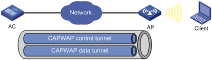
CAPWAP tunnel
CAPWAP defines how an AP communicates with an AC. It provides a generic encapsulation and transport mechanism between AP and AC. CAPWAP uses UDP and supports both IPv4 and IPv6.
As shown in Figure 1, an AC and an AP establish a data tunnel to forward data packets and a control tunnel to forward control packets.
AC discovery
After starting up with zero configurations, an AP automatically creates VLAN-interface 1 and enables the DHCP client, DHCPv6 client, and DNS features on the interface. Then it obtains its own IP address from the DHCP server and discovers ACs by using the following methods:
· Static IP address:
If AC IP addresses have been manually configured for the AP, the AP sends a unicast discovery request to each AC IP address to discover ACs.
· DHCP options:
a. The AP obtains AC IPv4 addresses from Option 138, Option 43, and IPv6 addresses from Option 52 sent from the DHCP server. It uses these addresses in descending order.
b. The AP sends a unicast discovery request to each received AC address to discover ACs.
For more information about DHCP options, see Layer 3—IP Services Configuration Guide.
· DNS:
a. The AP obtains the domain name suffix from the DHCP server.
b. The AP adds the suffix to the host name.
c. The DNS server translates the domain name into IP addresses.
d. The AP sends a unicast discovery request to each IP address to discover ACs.
For more information about DNS, see Layer 3—IP Services Configuration Guide.
· Broadcast:
The AP broadcasts discovery requests to IP address 255.255.255.255 to discover ACs.
· IPv4 multicast:
The AP sends multicast discovery requests to IPv4 address 224.0.1.140 to discover ACs.
· IPv6 multicast:
The AP sends multicast discovery requests to IPv6 address FF0E::18C to discover ACs.
The methods of static IP address, DHCPv4 options, broadcast, IPv4 multicast, IPv4 DNS, IPv6 multicast, DHCPv6 option, and IPv6 DNS are used in descending order.
The AP does not stop AC discovery until it establishes a CAPWAP tunnel with one of the discovered ACs.
CAPWAP tunnel establishment
Figure 2 Establishing a CAPWAP tunnel
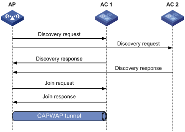
As shown in Figure 2, the AP and an AC establish a CAPWAP tunnel by using the following procedure:
1. The AP sends a discovery request to each AC to discover ACs.
2. Upon receiving the discovery request, an AC determines whether to send a discovery response by performing the following steps:
a. Identifies whether the discovery request is a unicast packet.
- Unicast packet—The AC proceeds to step b.
- Broadcast or multicast packet—The AC proceeds to step b if it is disabled with the feature of responding to only unicast discovery requests. If this feature is enabled, the AC does not send a discovery response.
- If manual AP configuration exists, the AC sends a discovery response to the AP. The discovery response contains information about whether the AC has the manual configuration for the AP, the AP connection priority, and the AC's load status.
- If no manual AP configuration exists, the AC proceeds to step c.
c. Identifies whether auto AP is enabled.
- If auto AP is enabled, the AC sends a discovery response to the AP. The discovery response contains the enabling status of auto AP, AP connection priority, and AC's load information.
- If auto AP is disabled, the AP does not send a discovery response.
3. Upon receiving the discovery responses, the AP selects the optimal AC in descending order.
? AC that saves information about the AP.
? AC where the auto AP feature is enabled.
? AC with higher AP connection priority.
? AC with the lighter load.
4. The AP sends a join request to the optimal AC.
5. After receiving the join request, the AC examines information in the request to determine whether to provide access services to the AP and sends a join response.
6. After receiving the join response, the AP examines the result code in the response:
? If the result code represents failure, the AP does not establish a CAPWAP tunnel with the AC.
? If the result code represents success, the AP establishes a CAPWAP tunnel with the AC.
AC rediscovery
An AC enabled with AC rediscovery will add the CAPWAP Control IP Address message element to the discovery responses sent to APs. Upon receiving such a discovery response, an AP establishes a CAPWAP tunnel by following this procedure:
1. Examines whether a discovery request has been sent to the IP address specified in the CAPWAP Control IP Address message element.
2. Performs either of the following operations:
? Sends a join request to the specified IP address representing the optimal AC for CAPWAP establishment if a discovery request has been sent.
? Sends a discovery request to each specified IP address to initiate a new AC discovery process if a discovery request has not been sent.
An AC disabled with AC rediscovery does not add the CAPWAP Control IP Address message element in discovery responses sent to APs. APs that receive the discovery responses will send join requests to the source IP address of the discovery responses to establish CAPWAP tunnels with the AC.
AP configuration methods
You can configure APs by using either of the following methods:
· Configure APs one by one in AP view.
· Assign APs to an AP group and configure the AP group in AP group view.
· Configure all APs in global configuration view.
For an AP, the priorities of the configuration in AP view, AP group view, and global configuration view are in descending order.
APDB
The Access Point Information Database (APDB) on an AC stores the following AP information:
· AP models.
· Hardware version and software version mappings.
· Information about radios supported by AP models.
? Number of radios.
? Radio type.
? Valid region code.
? Valid antenna type.
? Maximum transmission power.
The AC can establish a CAPWAP tunnel with an AP only when the APDB contains the corresponding AP model information.
You can use the system script and user scripts to manage data in the APDB. The system script is released with the AC software version, and it is automatically loaded each time the AC starts. If you need to add new AP models, upgrade the AC software version (see Fundamentals Configuration Guide) or create a user script and load it on the AC (see "Loading an APDB user script").
Protocols and standards
· RFC 5415, Control And Provisioning of Wireless Access Points (CAPWAP) Protocol Specification
· RFC 5417, Control And Provisioning of Wireless Access Points (CAPWAP) Access Controller DHCP Option
Command and hardware compatibility
The WX1800H series access controllers do not support the slot keyword or the slot-number argument.
Configuration task list
|
Tasks at a glance |
|
(Required.) Configuring CAPWAP tunnel establishment |
|
(Optional.) Configuring AC rediscovery |
|
(Optional.) Upgrading APs' software |
|
(Optional.) Configuring a CAPWAP tunnel |
|
(Optional.) Configuring AC request retransmission |
|
(Optional.) Setting the statistics report interval |
|
(Optional.) Configuring remote AP |
|
(Optional.) Configuring the default input power level |
|
(Optional.) Enabling or disabling USB interfaces for APs |
|
(Optional.) Resetting APs |
|
(Optional.) Renaming a manual AP |
|
(Optional.) Managing the file system of an AP |
|
(Optional.) Configuring an AP group |
|
(Optional.) Preprovisioning APs |
|
(Optional.) Enabling SNMP notifications |
|
(Optional.) Loading an APDB user script |
|
(Optional.) Enabling service anomaly detection |
Configuration prerequisites
Before you manage APs, complete the following tasks:
· Create a DHCP address pool on the DHCP server to assign IP addresses to APs.
· If DHCP options are used for AC discovery, configure Option 138, Option 43, or Option 52 in the specified DHCP address pool on the DHCP server.
· If DNS is used for AC discovery, configure the IP address of the DNS server and the AC domain name suffix in the specified DHCP address pool on the DHCP server. Then configure the mapping between the domain name and the AC IP address on the DNS server.
· Make sure the APs and the AC can reach each other.
For more information about DHCP and DNS, see Layer 3—IP Services Configuration Guide.
Configuring CAPWAP tunnel establishment
Creating a manual AP
You can create a manual AP on the AC according to the AP model, serial ID, and MAC address of the AP you are using. An AP prefers to establish a CAPWAP tunnel with an AC that saves the manual AP configuration.
To create a manual AP:
|
Step |
Command |
Remarks |
|
1. Enter system view. |
system-view |
|
|
2. Create a manual AP and enter its view. |
wlan ap ap-name [ model model-name ] |
By default, no manual AP exists. You must specify the model name when you create an AP. |
|
3. Specify the serial ID or the MAC address for the AP. |
· Specify the serial ID for the AP: · Specify the MAC address for the AP: |
Use either command. |
|
4. (Optional.) Set a description for the AP. |
description text |
By default, no description is set for an AP. |
Managing auto APs
The auto AP feature enables APs to connect to an AC without manual AP configuration. The AC names auto APs by their MAC addresses. This feature simplifies configuration when you deploy a large number of APs in a WLAN.
Enabling the auto AP feature
|
Step |
Command |
Remarks |
|
1. Enter system view. |
system-view |
N/A |
|
2. Enable the auto AP feature. |
wlan auto-ap enable |
By default, the auto AP feature is disabled. |
Converting auto APs to manual APs
You must convert auto APs to manual APs after they come online because of the following reasons:
· You can modify auto AP configuration only when they are converted to manual APs.
· For security purposes, auto APs can re-associate with the AC upon an AC reboot or CAPWAP tunnel termination only when they are converted to manual APs.
To convert auto APs to manual APs:
|
Step |
Command |
Remarks |
|
1. Enter system view. |
system-view |
N/A |
|
2. Convert auto APs to manual APs. |
· Convert online auto APs to manual APs: · Convert auto APs to manual APs
automatically after auto APs come online: |
Use either command. By default, auto APs are not converted to manual APs. The wlan auto-persistent enable command does not take effect on auto APs that are already online. |
Setting the AP connection priority for the AC
ACs put their AP connection priorities in discovery responses. An AP prefers to establish a CAPWAP tunnel with an AC that has higher connection priority when either of the following conditions exists:
· Multiple ACs have manual AP configuration for the AP.
· No AC has manual AP configuration for the AP, but multiple ACs are enabled with the auto AP feature.
Setting the AP connection priority in AP view
|
Step |
Command |
Remarks |
|
1. Enter system view. |
system-view |
N/A |
|
2. Enter AP view. |
wlan ap ap-name [ model model-name ] |
N/A |
|
3. Set the AP connection priority for the AC. |
priority priority |
By default, an AP uses the configuration in AP group view. A larger number represents a higher priority. |
Setting the AP connection priority in AP group view
|
Step |
Command |
Remarks |
|
1. Enter system view. |
system-view |
N/A |
|
2. Enter AP group view. |
wlan ap-group group-name |
N/A |
|
3. Set the AP connection priority for the AC. |
priority priority |
The default setting is 4. A larger number represents a higher priority. |
Enabling the AC to respond to only unicast discovery requests
An AP can send unicast, multicast, and broadcast discovery requests to discover ACs. This feature enables an AC to respond to only unicast discovery requests.
To enable the AC to respond to only unicast discovery requests:
|
Step |
Command |
Remarks |
|
1. Enter system view. |
system-view |
N/A |
|
2. Enable the AC to respond to only unicast discovery requests. |
wlan capwap discovery-policy unicast |
By default, the AC can respond to unicast, multicast, and broadcast discovery requests. |
Enabling an AP to prefer discovering ACs by IPv6 address
This feature enables an AP to discover ACs by using the static IP addresses, IPv6 multicast, DHCPv6 option, IPv6 DNS, DHCPv4 options, broadcast/IPv4 multicast, and IPv4 DNS successively. If the AP connects to an AC successfully with a discovered IP address, it stops AC discovery.
Enabling an AP to prefer discovering ACs by IPv6 address in AP provision view
|
Step |
Command |
Remarks |
|
1. Enter system view. |
system-view |
N/A |
|
2. Enter AP view. |
wlan ap ap-name |
N/A |
|
3. Enter AP provision view. |
provision |
N/A |
|
4. Enable an AP to prefer discovering ACs by IPv6 address. |
ac discovery policy ipv6 |
By default, an AP uses the configuration in AP group provision view. |
Enabling an AP to prefer discovering ACs by IPv6 address in AP group provision view
|
Step |
Command |
Remarks |
|
1. Enter system view. |
system-view |
N/A |
|
2. Enter AP group view. |
wlan ap-group group-name |
N/A |
|
3. Enter AP group provision view. |
provision |
N/A |
|
4. Enable an AP to prefer discovering ACs by IPv6 address. |
ac discovery policy ipv6 |
By default, an AP prefers to discover ACs by IPv4 address. |
Configuring AC rediscovery
Configuring AC rediscovery in AP view
|
Step |
Command |
Remarks |
|
1. Enter system view. |
system-view |
N/A |
|
2. Enter AP view. |
wlan ap ap-name [ model model-name ] |
N/A |
|
control-address { disable | enable } |
By default, an AP uses the configuration in AP group view. If no configuration exists in AP group view, the AP uses the configuration in global configuration view. |
|
|
4. Specify the IP address to be carried in the CAPWAP Control IP Address message element. |
control-address { ip ipv4-address | ipv6 ipv6-address } |
By default, an AP uses the configuration in AP group view. If no configuration exists in AP group view, the AP uses the configuration in global configuration view. You can specify a maximum of three IPv4 or IPv6 addresses to be added in the CAPWAP Control IP Address message element. |
Configuring AC rediscovery in AP group view
|
Step |
Command |
Remarks |
|
1. Enter system view. |
system-view |
N/A |
|
2. Enter AP group view. |
wlan ap-group group-name |
N/A |
|
3. Configure AC rediscovery. |
control-address { disable | enable } |
By default, an AP uses the configuration in global configuration view. |
|
4. Specify the IP address to be carried in the CAPWAP Control IP Address message element. |
control-address { ip ipv4-address | ipv6 ipv6-address } |
By default, an AP uses the configuration in global configuration view. You can specify a maximum of three IPv4 or IPv6 addresses to be added in the CAPWAP Control IP Address message element. |
Configuring AC rediscovery in global configuration view
|
Step |
Command |
Remarks |
|
1. Enter system view. |
system-view |
N/A |
|
2. Enter global configuration view. |
wlan global-configuration |
N/A |
|
3. Configure AC rediscovery. |
control-address { disable | enable } |
By default, AC rediscovery is disabled. |
|
4. Specify the IP address to be carried in the CAPWAP Control IP Address message element. |
control-address { ip ipv4-address | ipv6 ipv6-address } |
By default, the IP address in the element is the AC's IP address. You can specify a maximum of three IPv4 or IPv6 addresses to be added in the CAPWAP Control IP Address message element. |
Upgrading APs' software
Overview
Software upgrade for an AP proceeds as follows:
1. The AP reports the software version and AP model information to the AC.
2. The AC examines the received AP software version.
? If a match is found, the AC establishes a CAPWAP tunnel with the AP.
? If no match is found, the AC sends a message that notifies the AP of the AP software version inconsistency.
3. Upon receiving the inconsistency message, the AP requests a software version from the AC.
4. The AC assigns the software version to the AP after receiving the request.
5. The AP upgrades the software version, and restarts to establish a CAPWAP tunnel with the AC.
Configuring software upgrade
The AC examines the AP software version while establishing the CAPWAP tunnel only when software upgrade is enabled. If this feature is disabled, the AC does not examine the software version of the AP and directly establishes a CAPWAP tunnel with the AP.
Configuring software upgrade in AP view
|
Step |
Command |
Remarks |
|
1. Enter system view. |
system-view |
N/A |
|
2. Enter AP view. |
wlan ap ap-name [ model model-name ] |
N/A |
|
3. Configure software upgrade. |
firmware-upgrade { disable | enable } |
By default, an AP uses the configuration in AP group view. If no software upgrade configuration exists in AP group view, the AP uses the configuration in global configuration view. |
Configuring software upgrade in AP group view
|
Step |
Command |
Remarks |
|
1. Enter system view. |
system-view |
N/A |
|
2. Enter AP group view. |
wlan ap-group group-name |
N/A |
|
3. Configure software upgrade. |
firmware-upgrade { disable | enable } |
By default, an AP uses the configuration in global configuration view. |
Configuring software upgrade in global configuration view
|
Step |
Command |
Remarks |
|
1. Enter system view. |
system-view |
N/A |
|
2. Enter global configuration view. |
wlan global-configuration |
N/A |
|
3. Configure software upgrade. |
firmware-upgrade { disable | enable } |
By default, the software upgrade feature is enabled. |
Configuring the mapping between a software version and a hardware version of an AP model
|
|
CAUTION: To avoid CAPWAP tunnel establishment failure, use this feature under the guidance of H3C Support. |
Perform this task to configure the mapping between a software version and a hardware version of an AP model for software upgrade.
Perform this task only when the AP software version for an AP model stored in the APDB is inconsistent with the software version you expect for the AP model. To display the AP software version for each AP model in the APDB, use the display wlan ap-model command.
To configure the mapping between a software version and a hardware version of an AP model:
|
Step |
Command |
Remarks |
|
1. Enter system view. |
system-view |
N/A |
|
2. Configure the mapping between a software version and a hardware version of an AP model. |
wlan apdb model-name hardware-version software-version |
By default, the software version for a hardware version of an AP model is the software version that is stored in APDB user scripts. |
Specifying the preferred location for the AC to obtain an AP image file
The AC assigns an AP image file to an AP if the AP requests a software version during CAPWAP tunnel establishment. You can specify the preferred location as the AC's RAM or local folder for the AC to obtain an AP image file. If the AC cannot obtain an AP image file from the preferred location, it obtains an AP image file from the other location. If no AP image file exists, the AC fails to obtain an image file and cannot assign a software version to the AP.
Configuration restrictions and guidelines
When you specify the preferred image location for the AC to obtain an AP image file, follow these restrictions and guidelines:
· The AC can assign only .ipe AP image files to APs.
· If you specify the local folder, make sure the AC uses a CF card as the default file system and the AP image file is stored in the root directory of the file system on the AC.
Configuration procedure
To specify the preferred location for the AC to obtain an AP image file:
|
Step |
Command |
Remarks |
|
1. Enter system view. |
system-view |
N/A |
|
2. Specify the preferred location for the AC to obtain an AP image file. |
wlan image-load filepath { local | ram } |
By default, the AC prefers the AP image file stored in the RAM when assigning a software version to an AP. |
Configuring a CAPWAP tunnel
Configuring CAPWAP tunnel latency detection
This feature enables an AC to detect the transmission latency of CAPWAP control frames or data frames from an AP to the AC and back.
This feature takes effect only on the master AC after a CAPWAP tunnel is established.
When an AP goes offline, CAPWAP tunnel latency detection automatically stops. To restart CAPWAP tunnel latency detection when the AP comes online, execute the tunnel latency-detect start command again.
To display CAPWAP tunnel latency information, use the display wlan tunnel latency ap name command.
To configure CAPWAP tunnel latency detection:
|
Step |
Command |
Remarks |
|
||
|
1. Enter system view. |
system-view |
N/A |
|
||
|
2. Enter AP view. |
wlan ap ap-name [ model model-name ] |
N/A |
|||
|
3. Configure CAPWAP tunnel latency detection. |
tunnel latency-detect { start | stop } |
By default, CAPWAP tunnel latency detection is not started. |
|
||
Setting the control tunnel keepalive time for an AP
An AP sends echo requests to the AC at the specified echo interval to identify whether the CAPWAP control tunnel is operating correctly. The AC responds by sending echo responses. If the AP does not receive any echo responses within the keepalive time, the AP terminates the connection. If the AC does not receive any echo requests within the keepalive time, the AC terminates the connection. The keepalive time is the echo interval multiplied by the maximum number of echo request transmission attempts.
Setting the control tunnel keepalive time for an AP in AP view
|
Step |
Command |
Remarks |
|
1. Enter system view. |
system-view |
N/A |
|
2. Enter AP view. |
wlan ap ap-name [ model model-name ] |
N/A |
|
3. Set the interval at which the AP sends echo requests. |
echo-interval interval |
By default, an AP uses the configuration in AP group view. |
|
4. Set the maximum number of echo request transmission attempts. |
echo-count count |
By default, an AP uses the configuration in AP group view. |
Setting the control tunnel keepalive time for APs in AP group view
|
Step |
Command |
Remarks |
|
1. Enter system view. |
system-view |
N/A |
|
2. Enter AP group view. |
wlan ap-group group-name |
N/A |
|
3. Set the interval at which the APs send echo requests. |
echo-interval interval |
The default setting is 10 seconds. |
|
4. Set the maximum number of echo request transmission attempts. |
echo-count count |
The default setting is 3. |
Setting the data tunnel keepalive time for an AP
An AP sends data channel keepalive packets to the AC at the specified keepalive time after a CAPWAP tunnel is established between the AP and the AC.
Setting the data tunnel keepalive time for an AP in AP view
|
Step |
Command |
Remarks |
|
1. Enter system view. |
system-view |
N/A |
|
2. Enter AP view. |
wlan ap ap-name [ model model-name ] |
N/A |
|
3. Set the data tunnel keepalive interval. |
keepalive-interval interval |
By default, an AP uses the configuration in AP group view. |
Setting the data tunnel keepalive time for APs in AP group view
|
Step |
Command |
Remarks |
|
1. Enter system view. |
system-view |
N/A |
|
2. Enter AP group view. |
wlan ap-group group-name |
N/A |
|
3. Set the data tunnel keepalive interval. |
keepalive-interval interval |
The default setting is 10 seconds. |
Setting the maximum fragment size for CAPWAP packets
Perform this task to prevent intermediate devices from dropping packets between AC and AP if the AP connects to the AC across the Internet.
Any maximum fragment size modification takes effect immediately on online APs.
Setting the maximum fragment size for CAPWAP packets in AP view
|
Step |
Command |
Remarks |
|
1. Enter system view. |
system-view |
N/A |
|
2. Enter AP view. |
wlan ap ap-name [ model model-name ] |
N/A |
|
3. Set the maximum fragment size for CAPWAP control or data packets. |
fragment-size { control control-size | data data-size } |
By default, an AP uses the configuration in AP group view. |
Setting the maximum fragment size for CAPWAP packets in AP group view
|
Step |
Command |
Remarks |
|
1. Enter system view. |
system-view |
N/A |
|
2. Enter AP group view. |
wlan ap-group group-name |
N/A |
|
3. Set the maximum fragment size for CAPWAP control or data packets. |
fragment-size { control control-size | data data-size } |
By default, the maximum fragment size for CAPWAP control packets and data packets is 1450 bytes and 1500 bytes, respectively. |
Setting the TCP MSS for CAPWAP tunnels
About setting the TCP MSS
Perform this task to set the value of the Maximum Segment Size (MSS) option in SYN packets transmitted over a CAPWAP tunnel.
The MSS option informs the receiver of the largest segment that the sender can accept. Each end announces its MSS during TCP connection establishment. If the size of a TCP segment is smaller than or equal to the MSS of the receiver, TCP sends the TCP segment without fragmentation. If not, TCP fragments the segment based on the receiver's MSS.
Procedure
|
Step |
Command |
Remarks |
|
1. Enter system view. |
system-view |
N/A |
|
2. Set the TCP MSS for CAPWAP tunnels. |
wlan tcp mss value |
The default setting is 1460 bytes. |
Configuring AC request retransmission
The AC transmits a request sent to an AP at the retransmission interval until the maximum number of request retransmission attempts is reached or a response is received.
Configuring AC request retransmission in AP view
|
Step |
Command |
Remarks |
|
1. Enter system view. |
system-view |
N/A |
|
2. Enter AP view. |
wlan ap ap-name [ model model-name ] |
N/A |
|
3. Set the maximum number of request retransmission attempts. |
retransmit-count value |
By default, an AP uses the configuration in AP group view. |
|
4. Set the interval at which an AC request is retransmitted. |
retransmit-interval interval |
By default, an AP uses the configuration in AP group view. |
Configuring AC request retransmission in AP group view
|
Step |
Command |
Remarks |
|
1. Enter system view. |
system-view |
N/A |
|
2. Enter AP group view. |
wlan ap-group group-name |
N/A |
|
3. Set the maximum number of request retransmission attempts. |
retransmit-count value |
The default setting is 3. |
|
4. Set the interval at which an AC request is retransmitted. |
retransmit-interval interval |
The default setting is 5 seconds. |
Setting the statistics report interval
Perform this task to change the interval for an AP to report its statistics. You can use these statistics to monitor the operating status of radios on the AP.
Setting the statistics report interval in AP view
|
Step |
Command |
Remarks |
|
1. Enter system view. |
system-view |
N/A |
|
2. Enter AP view. |
wlan ap ap-name [ model model-name ] |
N/A |
|
3. Set the statistics report interval. |
statistics-interval interval |
By default, an AP uses the configuration in AP group view. |
Setting the statistics report interval in AP group view
|
Step |
Command |
Remarks |
|
1. Enter system view. |
system-view |
N/A |
|
2. Enter AP group view. |
wlan ap-group group-name |
N/A |
|
3. Set the statistics report interval. |
statistics-interval interval |
The default setting is 50 seconds. |
Configuring remote AP
An AP stops providing services for clients when the tunnel between the AP and the AC is disconnected. This feature enables an AP to automatically perform the following tasks when the tunnel between the AP and the AC is disconnected:
· Forwards client traffic.
· Provides client access services if local authentication is enabled and association is enabled at the AP.
Remote AP takes effect only on APs that operate in local forwarding mode.
When the tunnel between the AC and AP is recovered, clients with the AC as the authenticator need reauthentication. Clients with the AP as the authenticator remain online.
Remote AP is applicable to telecommuting, small branches, and SOHO solutions.
Configuring remote AP in AP view
|
Step |
Command |
Remarks |
|
1. Enter system view. |
system-view |
N/A |
|
2. Enter AP view. |
wlan ap ap-name [ model model-name ] |
N/A |
|
3. Configure remote AP. |
hybrid-remote-ap { disable | enable } |
By default, an AP uses the configuration in AP group view. |
Configuring remote AP in AP group view
|
Step |
Command |
Remarks |
|
1. Enter system view. |
system-view |
N/A |
|
2. Enter AP group view. |
wlan ap-group group-name |
N/A |
|
3. Configure remote AP. |
hybrid-remote-ap { disable | enable } |
By default, remote AP is disabled. |
Configuring the default input power level
|
|
NOTE: Support for this feature depends on the device model. |
Configure the default input power level for an AP in case the AP cannot obtain its input power level at startup.
Input power level overview
An AP automatically performs power supply mode detection to obtain its input power level at startup. If the AP fails to obtain the input power level, it operates at the low power level before associating with an AC. After the association, it operates at the configured default input power level.
An AP can be powered through a power adapter or through its PoE or PoE+ ports. The following table shows the relationship between the AP's power supply mode and input power level:
|
Power supply mode |
Input power level |
|
· Power adapter. · Multiple PoE+ ports. · Combination of PoE and PoE+ ports. |
High |
|
· Single PoE+ port · Multiple PoE ports |
Middle |
|
Single PoE port |
Low |
An AP's support for MIMO modes and USB interfaces varies by input power level, as shown in Table 1.
Table 1 AP's support for MIMO modes and USB interfaces
|
Input power level |
Supported MIMO modes |
Whether USB interfaces can be enabled |
|
High |
1×1, 2×2, 3×3, and 4×4. |
Yes. |
|
Middle |
1×1, 2×2, 3×3, and 4×4. |
Yes when the MIMO mode is 1×1 or 2×2. |
|
Low |
1×1. |
No. |
Configuration restrictions and guidelines
When you configure the default input power level for an AP, make sure the setting matches its power mode. An excessively low input power level prevents the AP from operating correctly. An excessively high input power level causes overload of the AP in case of power shortage.
Configuring the default input power level in AP view
|
Step |
Command |
Remarks |
|
1. Enter system view. |
system-view |
N/A |
|
2. Enter AP view. |
wlan ap ap-name [ model model-name ] |
N/A |
|
3. Configure the default input power level. |
power-level default { high | low | middle } |
By default, an AP uses the configuration in AP group's AP model view. |
Configuring the default input power level in AP group's AP model view
|
Step |
Command |
Remarks |
|
1. Enter system view. |
system-view |
N/A |
|
2. Enter AP group view. |
wlan ap-group group-name |
N/A |
|
3. Enter AP model view. |
ap-model ap-model |
N/A |
|
4. Configure the default input power level. |
power-level default { high | low | middle } |
The default setting is middle. |
Enabling or disabling USB interfaces for APs
|
|
NOTE: Support for this feature depends on the AP model. |
After you enable USB interfaces for an AP, the USB interfaces are active only when either of the following requirements is met:
· The input power level of the AP is high.
· The input power level of the AP is middle and the MIMO mode is 1×1 or 2×2.
For information about input power levels, see "Configuring the default input power level." For information about MIMO modes, see "Configuring radio management."
Enabling or disabling USB interfaces in AP view
|
Step |
Command |
Remarks |
|
1. Enter system view. |
system-view |
N/A |
|
2. Enter AP view. |
wlan ap ap-name [ model model-name ] |
N/A |
|
3. Enable or disable USB interfaces. |
usb { enable | disable } |
By default, an AP uses the configuration in AP group's AP model view. |
Enabling or disabling USB interfaces in AP group' AP model view
|
Step |
Command |
Remarks |
|
1. Enter system view. |
system-view |
N/A |
|
2. Enter AP group view. |
wlan ap-group group-name |
N/A |
|
3. Enter AP model view. |
ap-model ap-model |
N/A |
|
4. Enable or disable USB interfaces. |
usb { enable | disable } |
By default, USB interfaces are disabled. |
Resetting APs
Perform the following task in user view:
|
Task |
Command |
|
Reset all APs or the specified AP. |
reset wlan ap { all | ap-group group-name | model model-name | name ap-name } |
Renaming a manual AP
|
Step |
Command |
|
1. Enter system view. |
system-view |
|
2. Rename a manual AP. |
wlan rename-ap ap-name new-ap-name |
Managing the file system of an AP
You can perform the following tasks on an AC to manage files for an AP after the AP establishes a CAPWAP tunnel with the AC:
· View file information for the AP.
· Delete a file from the AP.
· Download an image file from the AC to the AP.
This feature takes effect only on master ACs.
To manage the file system of an AP:
|
Step |
Command |
|
1. Display information about files or file folders on an AP. |
display wlan ap files name ap-name |
|
2. Enter system view. |
system-view |
|
3. Enter AP view. |
wlan ap ap-name [ model model-name ] |
|
4. Delete a file from the AP. |
delete file filename |
|
5. Download an image file to the AP. |
Configuring an AP group
This feature enables you to configure multiple APs in a batch to reduce configuration workload.
APs in an AP group use the configuration of the group. By default, all APs belong to the default AP group default-group. The default AP group cannot be created or deleted.
You can configure AP grouping rules by AP names, serial IDs, MAC addresses, and IP addresses to add APs to the specified AP group. Priorities of these grouping rules are in descending order. If an AP does not match any grouping rules, it is added to the default AP group.
Configuration restrictions and guidelines
When you configure an AP group, follow these restrictions and guidelines:
· An AP can be added to only one AP group.
· You cannot delete an AP group that contains an AP.
· You cannot create grouping rules for the default AP group.
· You cannot create the same grouping rule for different AP groups. If you do so, the most recent configuration takes effect.
· The configuration priorities for an AP in AP view, AP group view, and global configuration view are in descending order. If no settings are configured in one view, the settings in the view with a lower priority are used. If no settings are configured in any one of the three views, the AP uses the default configuration in the view that has the lowest priority.
· AP grouping rules by IPv4 or IPv6 addresses for an AP group or for different AP groups cannot overlap with each other.
· An AP group supports a maximum of 32 AP grouping rules by IPv4 or IPv6 addresses.
Creating an AP group
|
Command |
Remarks |
|
|
1. Enter system view. |
N/A |
|
|
2. Create an AP group and enter its view. |
By default, there is a default AP group. |
|
|
3. (Optional.) Set a description for the AP group. |
By default, no description is set for an AP group. |
|
|
4. Create an AP grouping rule by AP names. |
N/A |
|
|
5. Create an AP grouping rule by serial IDs. |
N/A |
|
|
6. Create an AP grouping rule by MAC addresses. |
N/A |
|
|
7. Create an AP grouping rule by IPv4 addresses. |
N/A |
|
|
8. Create an AP grouping rule by IPv6 addresses. |
if-match ipv6 { ipv6-address prefix-length | ipv6-address/prefix-length } |
N/A |
|
9. (Optional.) Create an AP regrouping rule. |
N/A |
Preprovisioning APs
AP preprovisioning allows you to configure network settings for fit APs on an AC. The AC automatically assigns these settings to the fit APs in run state through CAPWAP tunnels in a batch. This reduces the work load in large WLAN networks.
You must save these settings in configuration file wlan_ap_prvs.xml for an AP.
This feature takes effect only on master ACs.
You can configure network settings in AP provision view or AP group provision view. Settings in AP provision view have a higher priority.
If you modify the preprovisioned settings of an AP, resave the settings in the preprovisioned configuration file.
The save wlan ap-provision command has the same effect as the reset wlan ap provision command if no preprovisioned settings exist.
Preprovisioned settings configured in provision view take effect immediately when you execute the save wlan ap provision command.
Cancellations of preprovisioned settings in provision view do not take effect when you execute the save wlan ap provision command. For the cancellations to take effect on an AP, restart the AP.
For the reset wlan ap provision command to take effect on an AP, restart the AP after execution.
Configuring preprovisioned settings for an AP
|
Step |
Command |
Remarks |
|
1. Enter system view. |
system-view |
N/A |
|
2. Enter AP view. |
N/A |
|
|
3. Enable AP preprovisioning and enter AP provision view. |
By default, an AP uses the configuration in AP group view. |
|
|
4. Specify an AC for the AP. |
ac { host-name host-name | ip ipv4-address | ipv6 ipv6-address } |
By default, an AP uses the configuration in AP group view. |
|
5. Specify an IPv4 address for the management VLAN interface. |
By default, no IPv4 address is specified for the management VLAN interface. |
|
|
6. Specify an IPv6 address for the management VLAN interface. |
ipv6 address { ipv6-address prefix-length | ipv6-address/prefix-length } |
By default, no IPv6 address is specified for the management VLAN interface. |
|
7. Set the gateway IP address. |
By default, no gateway IP address is specified for an AP. |
|
|
8. Specify a DNS server. |
By default, an AP uses the configuration in AP group view. |
|
|
9. Set a DNS domain name suffix. |
By default, an AP uses the configuration in AP group view. |
Configuring network settings for an AP group
|
Step |
Command |
Remarks |
|
1. Enter system view. |
system-view |
N/A |
|
2. Enter AP group view. |
N/A |
|
|
3. Enable AP preprovisioning and enter AP group provision view. |
provision |
By default, AP preprovisioning is disabled. |
|
4. Specify an AC. |
ac { host-name host-name | ip ip-address | ipv6 ipv6-address } |
By default, no static AC is specified for an AP. |
|
5. Specify a DNS server. |
dns server { ip ip-address | ipv6 ipv6-address } |
By default, no DNS server is specified for an AP. |
|
6. Set a domain name suffix for the DNS server. |
dns domain domain-name |
By default, no domain name suffix is specified for a DNS server. |
Assigning preprovisioned settings to APs
Perform this task to enable the AC to assign preprovisioned settings to an AP with which the AC has established a CAPWAP tunnel. The preprovisioned settings will be saved to configuration file wlan_ap_prvs.xml on the AP, and the settings will overwrite the network settings saved in the configuration file.
You can use either of the following methods to assign preprovisioned settings to an AP:
· Manual configuration—You save the preprovisioned settings to configuration file wlan_ap_prvs.xml on the AP after it comes online.
Modifying the AC address configuration in the configuration file of the AP will trigger a new optimal AC selection process. Then the AP will terminate the original CAPWAP tunnel and establish a CAPWAP tunnel with the new AC.
· Auto assignment of preprovisioned settings—The preprovisioned settings are assigned to an AP when it is coming online. The AP will establish a CAPWAP tunnel with the AC specified in the preprovisioned settings. For information about optimal AC selection , see "CAPWAP tunnel establishment."
Saving the network settings to the configuration file on an AP
Perform the following task in any view:
|
Task |
Command |
|
Save the network settings to the preprovisioned configuration file wlan_ap_prvs.xml on the specified AP or all APs. |
Configuring auto assignment of preprovisioned settings
To configure auto assignment of preprovisioned settings in AP view:
|
Step |
Command |
Remarks |
|
1. Enter system view. |
system-view |
N/A |
|
2. Enter AP view. |
wlan ap ap-name [ model model-name ] |
N/A |
|
3. Configure auto assignment of preprovisioned settings for the AP. |
provision auto-update { disable | enable } |
By default, an AP uses the configuration in AP group view. |
To configure auto assignment of preprovisioned settings in AP group view:
|
Step |
Command |
Remarks |
|
1. Enter system view. |
system-view |
N/A |
|
2. Enter AP group view. |
wlan ap-group group-name |
N/A |
|
3. Configure auto assignment of preprovisioned settings for APs in the AP group. |
provision auto-update { disable | enable } |
By default, auto assignment of preprovisioned settings is disabled. |
Configuring auto loading of preprovisioned settings
Auto loading of preprovisioned settings ensures successful CAPWAP tunnel establishment between AP and AC. An AP uses the following procedure to discover an AC when you enable this feature:
1. Uses the preprovisioned settings to discover an AC that has the AP's manual or auto AP configuration.
2. Reboots and uses other methods to discover ACs if AC discovery fails.
3. Reboots and uses the preprovisioned settings again to discover ACs if the AP still fails to discover the target AC.
This AC discovery process will be repeated until the AP discovers the target AC to establish a CAPWAP tunnel.
Configuring auto loading of preprovisioned settings for an AP
|
Step |
Command |
Remarks |
|
1. Enter system view. |
system-view |
N/A |
|
2. Enter AP view. |
wlan ap ap-name [ model model-name ] |
N/A |
|
3. Configure auto loading of preprovisioned settings for the AP. |
By default, an AP uses the configuration in AP group view. |
Configuring auto loading of preprovisioned settings for an AP group
|
Step |
Command |
Remarks |
|
1. Enter system view. |
system-view |
N/A |
|
2. Enter AP group view. |
wlan ap-group group-name |
N/A |
|
3. Configure auto loading of preprovisioned settings for APs in the AP group. |
provision auto-recovery { disable | enable } |
By default, auto loading of preprovisioned settings is enabled. |
Enabling SNMP notifications
To report critical WLAN events to an NMS, enable SNMP notifications. For WLAN event notifications to be sent correctly, you must also configure SNMP as described in Network Management and Monitoring Configuration Guide.
To enable SNMP notifications:
|
Command |
Remarks |
|
|
1. Enter system view. |
system-view |
N/A |
|
2. Enable SNMP notifications. |
· Enable SNMP notifications for AP management: · Enable SNMP notifications for CAPWAP: |
By default, SNMP notifications for AP management and CAPWAP are disabled. |
Loading an APDB user script
Perform this task to add new AP models to the APDB without upgrading AC software.
Configuration restrictions and guidelines
When you load an APDB user script, follow these restrictions and guidelines:
· Make sure the user script is valid. Invalid scripts can cause loading failure.
· The AP models in the user script must be different from the AP models in the system script.
· If you load multiple user scripts on the AC, the most recently loaded user script overwrites the old user scripts.
· If you rename the user script in the file system, reload the user script to prevent AP model configuration in the user script from being lost after an AC reboot.
· If you replace the user script with a new user script in the file system, reload the new user script. If the new user script does not include AP model information saved in the replaced user script, the AP model information will be lost after an AC reboot.
· If you delete a user script in the file system, the AP model configuration in the user script will be lost after an AC reboot.
If an old user script already exists, follow these restrictions and guidelines when you load an APDB user script:
· If a manual AP or an online auto AP whose model is listed in the old user script exists ,you can load a new user script only when you delete the corresponding AP model information on the AC.
· If APs of an AP model listed in the old user script have been added to an AP group, you can load a new user script only when you remove the APs from the AP group.
· If the old user script includes an AP model whose software version was already configured, you can load a new user script only when you use the wlan apdb command to restore the original software version.
Configuration procedure
To load an APDB user script:
|
Step |
Command |
Remarks |
|
1. Enter system view. |
system-view |
N/A |
|
2. Load an APDB user script. |
wlan apdb file user.apdb |
By default, no user script is loaded on the AC. |
Enabling service anomaly detection
Perform this task on the master AC in an IRF fabric.
This feature enables an AC to check service status and start a 10-minute timer upon detecting that no APs are associated with the AC.
When the timer expires, the AC performs either of the following operations:
· Restarts if no AP is online.
· Deletes the timer if a minimum of one AP is online.
If APs come online and then all go offline before the timer expires, the AC restarts the 10-minute timer upon detecting that the last online AP goes offline.
As a best practice, enable this feature for an AC to recover automatically in case of service anomaly.
To enable service anomaly detection:
|
Step |
Command |
Remarks |
|
1. Enter system view. |
system-view |
N/A |
|
2. Enable service anomaly detection. |
wlan detect-anomaly enable |
By default, service anomaly detection is enabled. |
Displaying and maintaining AP management
Setting a LED lighting mode
You can configure LEDs on an AP to flash in the following modes:
· quiet—All LEDs are off.
· awake—All LEDs flash once every minute. Support for this mode depends on the AP model.
· always-on—All LEDs are steady on. Support for this mode depends on the AP model.
· normal—How LEDs flash in this mode varies by AP model. This mode can identify the running status of an AP.
If you set the LED lighting mode to awake or always-on in AP group view, the setting takes effect only on member APs that support the specified LED lighting mode.
Setting a LED lighting mode in AP view
|
Step |
Command |
Remarks |
|
1. Enter system view. |
system-view |
N/A |
|
2. Enter AP view. |
wlan ap ap-name [ model model-name ] |
N/A |
|
3. Set a LED lighting mode. |
led-mode { always-on | awake | normal | quiet } |
By default, an AP uses the configuration in AP group view. |
Setting a LED lighting mode in AP group view
|
Step |
Command |
Remarks |
|
1. Enter system view. |
system-view |
N/A |
|
2. Enter AP group view. |
wlan ap-group group-name |
By default, the default AP group default-group exists and it cannot be deleted. |
|
3. Set a LED lighting mode. |
led-mode { always-on | awake | normal | quiet } |
By default, the LED lighting mode is normal. |
Displaying AP management information
Execute display commands in any view.
|
Task |
Command |
|
Display information about all APs or the specified AP. |
display wlan ap { all | name ap-name } [ verbose ] |
|
Display address information for all APs or the specified AP. |
display wlan ap { all | name ap-name } address |
|
Display configuration status of CAPWAP features. |
display wlan ap all feature capwap |
|
Display AP connection records on the AC. |
display wlan ap connection record { all | name ap-name } |
|
Display AP online duration. |
display wlan ap online-time { all | name ap-name } |
|
Display the reboot logs of the specified AP. |
display wlan ap reboot-log name ap-name |
|
Display running configuration for all APs or the specified AP. |
display wlan ap running-configuration { all | ap-name ap-name } [ verbose ] |
|
Display association failure records for APs. |
display wlan ap statistics association-failure-record |
|
Display online AP quantity records. |
display wlan ap statistics online-record [ datetime date time [ count count ] ] |
|
Display CAPWAP tunnel down records. |
display wlan ap statistics tunnel-down-record |
|
Display information about all AP groups or the specified AP group. |
display wlan ap-group [ brief | name group-name ] |
|
Display AP model information. |
display wlan ap-model { all | name model-name } |
|
Display tunnel latency information for the specified CAPWAP tunnel. |
display wlan tunnel latency ap name ap-name |
|
Display information about distribution of attached APs for ACs. |
display wlan ap-distribution { all | slot slot-number } |
|
Display the attachment location of an AP. |
display wlan ap-distribution ap-name ap-name |
Clearing AP management information
Execute reset commands in user view.
|
Task |
Command |
|
Clear the reboot logs of all APs or the specified AP. |
reset wlan ap reboot-log { all | name ap-name } |
|
Clear tunnel latency information for all CAPWAP tunnels or the specified CAPWAP tunnel. |
|
|
Delete the configuration file wlan_ap_prvs.xml from all APs or the specified AP. |
AP management configuration examples
CAPWAP tunnel establishment through DHCP configuration example
Network requirements
As shown in Figure 3, configure the AP to obtain its IP address and AC IP address from the DHCP server through DHCP Option 43. The AP uses the IP address of the AC to establish a CAPWAP tunnel with the AC.

Configuration procedures
1. Configure the DHCP server:
# Enable the DHCP service.
[DHCP server] dhcp enable
# Configure DHCP address pool 1.
[DHCP server] dhcp server ip-pool 1
[DHCP server-dhcp-pool-1] network 1.1.1.0 mask 255.255.255.0
# Configure Option 43 to specify the IP address of the AC in address pool 0. The right-most bytes 01010103 (1.1.1.3) represents the IP address of the AC.
[DHCP server-dhcp-pool-1] option 43 hex 800700000101010103
[DHCP Server-dhcp-pool-1] quit
[DHCP Server] quit
2. Configure the AC:
# Set the IP address of VLAN-interface 1 on the AC to 1.1.1.3/24.
[AC] interface vlan-interface 1
[AC-Vlan-interface1] ip address 1.1.1.3 24
[AC-Vlan-interface1] quit
# Create AP ap1 with model WA536-WW, and set its serial ID to 219801A1NQB117012935.
[AC] wlan ap ap1 model WA536-WW
[AC-wlan-ap-ap1] serial-id 219801A1NQB117012935
[AC-wlan-ap-ap1] quit
# Start up the AP. The AP performs the following operations:
? Obtains its IP address 1.1.1.2 from the DHCP server.
? Obtains the IP address of the AC through Option 43.
? Establishes a CAPWAP tunnel with the AC.
Verifying the configuration
# Verify the following information:
· The AP obtains the IP address of the AC through DHCP.
· The AP and the AC have established a CAPWAP tunnel.
· The AP is in Run state.
[AC] display wlan ap name ap1 verbose
AP ID : 1
AP group name : default-group
State : Run
Backup type : Master
Online time : 0 days 1 hours 25 minutes 12 seconds
System up time : 0 days 2 hours 22 minutes 12 seconds
Model : WA536-WW
Region code : CN
Region code lock : Disable
Serial ID : 219801A1NQB117012935
MAC address : 0AFB-423B-893C
IP address : 192.168.1.50
UDP control port number : 18313
UDP data port number : N/A
H/W version : Ver.C
S/W version : R2206P02
Boot version : 1.01
USB state : N/A
Power Level : N/A
PowerInfo : N/A
Description : wtp1
Priority : 4
Echo interval : 10 seconds
Echo count : 3 counts
Keepalive interval : 10 seconds
Statistics report interval : 50 seconds
Fragment size (data) : 1500
Fragment size (control) : 1450
MAC type : Local MAC & Split MAC
Tunnel mode : Local Bridging & 802.3 Frame & Native Frame
Discovery type : DHCP
Retransmission count : 3
Retransmission interval : 5 seconds
Firmware upgrade : Enabled
Sent control packets : 1
Received control packets : 1
Echo requests : 147
Lost echo responses : 0
Average echo delay : 3
Last reboot reason : User soft reboot
Latest IP address : 10.1.0.2
Tunnel down reason : Request wait timer expired
Connection count : 1
Backup Ipv4 : Not configured
Backup Ipv6 : Not configured
Tunnel encryption : Disabled
LED mode : Normal
Remote configuration : Enabled
Radio 1:
Basic BSSID : 7848-59f6-3940
Admin state : Up
Radio type : 802.11ac
Antenna type : internal
Client dot11ac-only : Disabled
Client dot11n-only : Disabled
Channel band-width : 20/40/80MHz
Active band-width : 20/40/80MHz
Secondary channel offset : SCB
Short GI for 20MHz : Supported
Short GI for 40MHz : Supported
Short GI for 80MHz : Supported
Short GI for 160MHz : Not supported
A-MSDU : Enabled
A-MPDU : Enabled
LDPC : Not Supported
STBC : Supported
Operational VHT-MCS Set:
Mandatory : Not configured
Supported : NSS1 0,1,2,3,4,5,6,7,8,9
NSS2 0,1,2,3,4,5,6,7,8,9
Multicast : Not configured
Operational HT MCS Set:
Mandatory : Not configured
Supported : 0, 1, 2, 3, 4, 5, 6, 7, 8, 9,
10, 11, 12, 13, 14, 15
Multicast : Not configured
Channel : 44(auto)
Channel usage(%) : 15
Max power : 20 dBm
Operational rate:
Mandatory : 6, 12, 24 Mbps
Multicast : Auto
Supported : 9, 18, 36, 48, 54 Mbps
Disabled : Not configured
Distance : 1 km
ANI : Enabled
Fragmentation threshold : 2346 bytes
Beacon interval : 100 TU
Protection threshold : 2346 bytes
Long retry threshold : 4
Short retry threshold : 7
Maximum rx duration : 2000 ms
Noise Floor : -102 dBm
Protection mode : cts-to-self
MU-TxBF : Enabled
SU-TxBF : Enabled
Continuous mode : N/A
HT protection mode : No protection
Radio 2:
Basic BSSID : 7848-59f6-3950
Admin state : Down
Radio type : 802.11ac
Antenna type : internal
Client dot11ac-only : Disabled
Client dot11n-only : Disabled
Channel band-width : 20/40/80MHz
Active band-width : 20/40/80MHz
Secondary channel offset : SCN
Short GI for 20MHz : Supported
Short GI for 40MHz : Supported
Short GI for 80MHz : Supported
Short GI for 160MHz : Not supported
A-MSDU : Enabled
A-MPDU : Enabled
LDPC : Not Supported
STBC : Supported
Operational HT MCS Set:
Mandatory : Not configured
Supported : NSS1 0,1,2,3,4,5,6,7,8,9
NSS2 0,1,2,3,4,5,6,7,8,9
Multicast : Not configured
Operational HT MCS Set:
Mandatory : Not configured
Supported : 0, 1, 2, 3, 4, 5, 6, 7, 8, 9,
10, 11, 12, 13, 14, 15
Multicast : Not configured
Channel : 149(auto)
Channel usage(%) : 0
Max power : 20 dBm
Operational rate:
Mandatory : 6, 12, 24 Mbps
Multicast : Auto
Supported : 9, 18, 36, 48, 54 Mbps
Disabled : Not configured
Distance : 1 km
ANI : Enabled
Fragmentation threshold : 2346 bytes
Beacon interval : 100 TU
Protection threshold : 2346 bytes
Long retry threshold : 4
Short retry threshold : 7
Maximum rx duration : 2000 ms
Noise floor : 0 dBm
Protection mode : cts-to-self
MU-TxBF : Enabled
SU-TxBF : Enabled
Continuous mode : N/A
HT protection mode : No protection
Radio 3:
Basic BSSID : N/A
Admin state : Down
Radio type : 802.11n(2.4GHz)
Antenna type : internal
Client dot11n-only : Disabled
Channel band-width : 20MHz
Active band-width : 20MHz
Secondary channel offset : SCN
Short GI for 20MHz : Supported
Short GI for 40MHz : Supported
A-MSDU : Enabled
A-MPDU : Enabled
LDPC : Not Supported
STBC : Supported
Operational HT MCS Set:
Mandatory : Not configured
Supported : 0, 1, 2, 3, 4, 5, 6, 7, 8, 9,
10, 11, 12, 13, 14, 15
Multicast : Not configured
Channel : 6(auto)
Channel usage(%) : 0
Max power : 20 dBm
Preamble type : Short
Operational rate:
Mandatory : 1, 2, 5.5, 11 Mbps
Multicast : Auto
Supported : 6, 9, 12, 18, 24, 36, 48, 54 Mbps
Disabled : Not configured
Distance : 1 km
ANI : Enabled
Fragmentation threshold : 2346 bytes
Beacon interval : 100 TU
Protection threshold : 2346 bytes
Long retry threshold : 4
Short retry threshold : 7
Maximum rx duration : 2000 ms
Noise floor : 0 dBm
Protection mode : cts-to-self
Continuous mode : N/A
HT protection mode : No protection
CAPWAP tunnel establishment through DHCPv6 configuration example
Network requirements
As shown in Figure 4, configure the AP to obtain its IP address and the AC's IP address from the DHCPv6 server through DHCP Option 52. The AP uses the IP address of the AC to establish a CAPWAP tunnel with the AC.
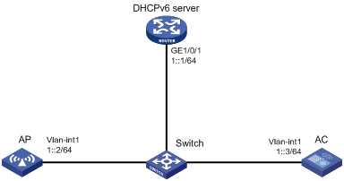
Configuration procedures
1. Configure the DHCPv6 server:
# Assign an IPv6 address to GigabitEthernet 1/0/1.
<DHCPv6 Server> system-view
[DHCPv6 Server] interface gigabitethernet 1/0/1
[DHCPv6 Server-GigabitEthernet1/0/1] ipv6 address 1::1/64
# Disable RA message advertising suppression.
[DHCPv6 Server-GigabitEthernet1/0/1] undo ipv6 nd ra halt
# Set the managed address configuration flag (M) to 1 in RA advertisements to be sent.
[DHCPv6 Server-GigabitEthernet1/0/1] ipv6 nd autoconfig managed-address-flag
# Set the other stateful configuration flag (O) to 1 in RA advertisements to be sent.
[DHCPv6 Server-GigabitEthernet1/0/1] ipv6 nd autoconfig other-flag
# Enable the DHCPv6 service on GigabitEthernet 1/0/1.
[DHCPv6 Server-GigabitEthernet1/0/1] ipv6 dhcp select server
[DHCPv6 Server-GigabitEthernet1/0/1] quit
# Create a DHCPv6 address pool, and specify an IPv6 subnet for dynamic allocation in the DHCPv6 address pool.
[DHCPv6 Server] ipv6 dhcp pool 1
[DHCPv6 Server-dhcp6-pool-1] network 1::0/64
[DHCPv6 Server-dhcp6-pool-1] quit
# Configure Option 52 that specifies an AC address 1::3 in DHCPv6 address pool 1.
[DHCPv6 Server-dhcp-pool-1] option 52 hex 00010000000000000000000000000003
[DHCPv6 Server-dhcp-pool-1] quit
[DHCPv6 Server] quit
2. Configure the AC:
# Set the IPv6 address of VLAN-interface 1 to 1::3/64.
<AC> system-view
[AC] interface vlan-interface 1
[AC-Vlan-interface1] ipv6 address 1::3 64
# Create an AP named ap1 and specify its model and serial ID.
[AC] wlan ap ap1 model WA536-WW
[AC-wlan-ap-ap1] serial-id 219801A1NQB117012935
[AC-wlan-ap-ap1] quit
# Start up the AP. The AP performs the following operations:
? Obtains its IPv6 address 1::2 from the DHCP server.
? Obtains the IPv6 address of the AC through Option 52.
? Establishes a CAPWAP tunnel with the AC.
Verifying the configuration
# Verify the following information:
· The AP obtains the IP address of the AC through DHCP.
· The AP and the AC have established a CAPWAP tunnel.
· The AP is in Run state.
[AC] display wlan ap name ap1 verbose
AP name : ap1
AP ID : 1
AP group name : default-group
State : Run
Backup type : Master
Online time : 0 days 1 hours 25 minutes 12 seconds
System up time : 0 days 2 hours 22 minutes 12 seconds
Model : WA536-WW
Region code : CN
Region code lock : Disable
Serial ID : 219801A1NQB117012935
MAC address : 0AFB-423B-893C
IP address : 1::2
UDP control port number : 18313
UDP data port number : N/A
H/W version : Ver.C
S/W version : R2206P02
Boot version : 1.01
USB state : N/A
Power Level : N/A
PowerInfo : N/A
Description : wtp1
Priority : 4
Echo interval : 10 seconds
Echo count : 3 counts
Keepalive interval : 10 seconds
Statistics report interval : 50 seconds
Fragment size (data) : 1500
Fragment size (control) : 1450
MAC type : Local MAC & Split MAC
Tunnel mode : Local Bridging & 802.3 Frame & Native Frame
Discovery type : DHCP
Retransmission count : 3
Retransmission interval : 5 seconds
Firmware upgrade : Enabled
Sent control packets : 1
Received control packets : 1
Echo requests : 147
Lost echo responses : 0
Average echo delay : 3
Last reboot reason : User soft reboot
Latest IP address : 10.1.0.2
Tunnel down reason : Request wait timer expired
Connection count : 1
Backup Ipv4 : Not configured
Backup Ipv6 : Not configured
Tunnel encryption : Disabled
LED mode : Normal
Remote configuration : Enabled
Radio 1:
Basic BSSID : 7848-59f6-3940
Admin state : Up
Radio type : 802.11ac
Antenna type : internal
Client dot11ac-only : Disabled
Client dot11n-only : Disabled
Channel band-width : 20/40/80MHz
Active band-width : 20/40/80MHz
Secondary channel offset : SCB
Short GI for 20MHz : Supported
Short GI for 40MHz : Supported
Short GI for 80MHz : Supported
Short GI for 160MHz : Not supported
A-MSDU : Enabled
A-MPDU : Enabled
LDPC : Not Supported
STBC : Supported
Operational VHT-MCS Set:
Mandatory : Not configured
Supported : NSS1 0,1,2,3,4,5,6,7,8,9
NSS2 0,1,2,3,4,5,6,7,8,9
Multicast : Not configured
Operational HT MCS Set:
Mandatory : Not configured
Supported : 0, 1, 2, 3, 4, 5, 6, 7, 8, 9,
10, 11, 12, 13, 14, 15
Multicast : Not configured
Channel : 44(auto)
Channel usage(%) : 15
Max power : 20 dBm
Operational rate:
Mandatory : 6, 12, 24 Mbps
Multicast : Auto
Supported : 9, 18, 36, 48, 54 Mbps
Disabled : Not configured
Distance : 1 km
ANI : Enabled
Fragmentation threshold : 2346 bytes
Beacon interval : 100 TU
Protection threshold : 2346 bytes
Long retry threshold : 4
Short retry threshold : 7
Maximum rx duration : 2000 ms
Noise Floor : -102 dBm
Protection mode : cts-to-selfs
MU-TxBF : Enabled
SU-TxBF : Enabled
Continuous mode : N/A
HT protection mode : No protection
Radio 2:
Basic BSSID : 7848-59f6-3950
Admin state : Down
Radio type : 802.11ac
Antenna type : internal
Client dot11n-only : Disabled
Channel band-width : 20/40/80MHz
Active band-width : 20/40/80MHz
Secondary channel offset : SCN
Short GI for 20MHz : Supported
Short GI for 40MHz : Supported
Short GI for 80MHz : Supported
Short GI for 160MHz : Not supported
A-MSDU : Enabled
A-MPDU : Enabled
LDPC : Not Supported
STBC : Supported
Operational HT MCS Set:
Mandatory : Not configured
Supported : NSS1 0,1,2,3,4,5,6,7,8,9
NSS2 0,1,2,3,4,5,6,7,8,9
Multicast : Not configured
Operational HT MCS Set:
Mandatory : Not configured
Supported : 0, 1, 2, 3, 4, 5, 6, 7, 8, 9,
10, 11, 12, 13, 14, 15
Multicast : Not configured
Channel : 149(auto)
Channel usage(%) : 0
Max power : 20 dBm
Operational rate:
Mandatory : 6, 12, 24 Mbps
Multicast : Auto
Supported : 9, 18, 36, 48, 54 Mbps
Disabled : Not configured
Distance : 1 km
ANI : Enabled
Fragmentation threshold : 2346 bytes
Beacon interval : 100 TU
Protection threshold : 2346 bytes
Long retry threshold : 4
Short retry threshold : 7
Maximum rx duration : 2000 ms
Noise floor : 0 dBm
Protection mode : cts-to-self
MU-TxBF : Enabled
SU-TxBF : Enabled
Continuous mode : N/A
HT protection mode : No protection
Radio 3:
Basic BSSID : N/A
Admin state : Down
Radio type : 802.11n(2.4GHz)
Antenna type : internal
Client dot11n-only : Disabled
Channel band-width : 20MHz
Active band-width : 20MHz
Secondary channel offset : SCN
Short GI for 20MHz : Supported
Short GI for 40MHz : Supported
A-MSDU : Enabled
A-MPDU : Enabled
LDPC : Not Supported
STBC : Supported
Operational HT MCS Set:
Mandatory : Not configured
Supported : 0, 1, 2, 3, 4, 5, 6, 7, 8, 9,
10, 11, 12, 13, 14, 15
Multicast : Not configured
Channel : 6(auto)
Channel usage(%) : 0
Max power : 20 dBm
Preamble type : Short
Operational rate:
Mandatory : 1, 2, 5.5, 11 Mbps
Multicast : Auto
Supported : 6, 9, 12, 18, 24, 36, 48, 54 Mbps
Disabled : Not configured
Distance : 1 km
ANI : Enabled
Fragmentation threshold : 2346 bytes
Beacon interval : 100 TU
Protection threshold : 2346 bytes
Long retry threshold : 4
Short retry threshold : 7
Maximum rx duration : 2000 ms
Noise floor : 0 dBm
Protection mode : cts-to-self
Continuous mode : N/A
HT protection mode : No protection
CAPWAP tunnel establishment through DNS configuration example
Network requirements
As shown in Figure 5, configure the AP to obtain the IP address of the AC through DNS to establish a CAPWAP tunnel with the AC.
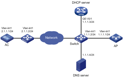
Configuration procedures
1. Configure the DHCP server:
# Enable the DHCP service, configure DHCP address pool 1, and set the domain name suffix of the AC to abc.
[DHCP server] dhcp enable
[DHCP server] dhcp server ip-pool 1
[DHCP server-dhcp-pool-1] network 1.1.1.0 mask 255.255.255.0
[DHCP server-dhcp-pool-1] domain-name abc
[DHCP server-dhcp-pool-1] dns-list 1.1.1.4
[DHCP server-dhcp-pool-1] gateway-list 1.1.1.2
[DHCP server-dhcp-pool-1] quit
[DHCP server] quit
2. Configure a mapping between domain name h3c.abc and IP address 2.1.1.1/24. For more information, see Layer 3—IP Services Configuration Guide. (Details not shown.)
3. Configure the AC:
# Set the IP address of VLAN-interface 1 to 2.1.1.1/24.
[AC] interface vlan-interface 1
[AC-Vlan-interface1] ip address 2.1.1.1 24
[AC-Vlan-interface1] quit
# Configure a default route with next hop address 2.1.1.2.
[AC] ip route-static 0.0.0.0 0 2.1.1.2
# Create AP ap1 and specify its model and serial ID.
[AC] wlan ap ap1 model WA536-WW
[AC-wlan-ap-ap1] serial-id 219801A1NQB117012935
# Start up the AP.
[AC-wlan-ap-ap1] quit
The AP performs the following operations:
? Obtains its IP address 1.1.1.1, the domain name suffix of the AC, and the IP address of the DNS server from the DHCP server.
? Adds the domain name suffix to the hostname.
? Informs the DNS client to translate the domain name into an IP address.
? Uses the IP address of the AC to establish a CAPWAP tunnel with the AC.
Verifying the configuration
# Verify the following information:
· The AP and the AC have established a CAPWAP tunnel.
· The AP is in Run state.
· The AP obtains the IP address of the AC through DNS.
[AC] display wlan ap name ap1 verbose
AP name : ap1
AP ID : 1
AP group name : default-group
State : Run
Backup type : Master
Online time : 0 days 1 hours 25 minutes 12 seconds
System up time : 0 days 2 hours 22 minutes 12 seconds
Model : WA536-WW
Region code : CN
Region code lock : Disable
Serial ID : 219801A1NQB117012935
MAC address : 0AFB-423B-893C
IP address : 1.1.1.1
UDP control port number : 18313
UDP data port number : N/A
H/W version : Ver.C
S/W version : R2206P02
Boot version : 1.01
USB state : N/A
Power Level : N/A
PowerInfo : N/A
Description : wtp1
Priority : 4
Echo interval : 10 seconds
Echo count : 3 counts
Keepalive interval : 10 seconds
Statistics report interval : 50 seconds
Fragment size (data) : 1500
Fragment size (control) : 1450
MAC type : Local MAC & Split MAC
Tunnel mode : Local Bridging & 802.3 Frame & Native Frame
Discovery type : DNS
Retransmission count : 3
Retransmission interval : 5 seconds
Firmware upgrade : Enabled
Sent control packets : 1
Received control packets : 1
Echo requests : 147
Lost echo responses : 0
Average echo delay : 3
Last reboot reason : User soft reboot
Latest IP address : 10.1.0.2
Tunnel down reason : Request wait timer expired
Connection count : 1
Backup Ipv4 : Not configured
Backup Ipv6 : Not configured
Tunnel encryption : Disabled
LED mode : Normal
Remote configuration : Enabled
Radio 1:
Basic BSSID : 7848-59f6-3940
Admin state : Up
Radio type : 802.11ac
Antenna type : internal
Client dot11ac-only : Disabled
Client dot11n-only : Disabled
Channel band-width : 20/40/80MHz
Active band-width : 20/40/80MHz
Secondary channel offset : SCB
Short GI for 20MHz : Supported
Short GI for 40MHz : Supported
Short GI for 80MHz : Supported
Short GI for 160MHz : Not supported
A-MSDU : Enabled
A-MPDU : Enabled
LDPC : Not Supported
STBC : Supported
Operational VHT-MCS Set:
Mandatory : Not configured
Supported : NSS1 0,1,2,3,4,5,6,7,8,9
NSS2 0,1,2,3,4,5,6,7,8,9
Multicast : Not configured
Operational HT MCS Set:
Mandatory : Not configured
Supported : 0, 1, 2, 3, 4, 5, 6, 7, 8, 9,
10, 11, 12, 13, 14, 15
Multicast : Not configured
Channel : 44(auto)
Channel usage(%) : 15
Max power : 20 dBm
Operational rate:
Mandatory : 6, 12, 24 Mbps
Multicast : Auto
Supported : 9, 18, 36, 48, 54 Mbps
Disabled : Not configured
Distance : 1 km
ANI : Enabled
Fragmentation threshold : 2346 bytes
Beacon interval : 100 TU
Protection threshold : 2346 bytes
Long retry threshold : 4
Short retry threshold : 7
Maximum rx duration : 2000 ms
Noise Floor : -102 dBm
Protection mode : cts-to-self
MU-TxBF : Enabled
SU-TxBF : Enabled
Continuous mode : N/A
HT protection mode : No protection
Radio 2:
Basic BSSID : 7848-59f6-3950
Admin state : Down
Radio type : 802.11ac
Antenna type : internal
Client dot11ac-only : Disabled
Client dot11n-only : Disabled
Channel band-width : 20/40/80MHz
Active band-width : 20/40/80MHz
Secondary channel offset : SCN
Short GI for 20MHz : Supported
Short GI for 40MHz : Supported
Short GI for 80MHz : Supported
Short GI for 160MHz : Not supported
A-MSDU : Enabled
A-MPDU : Enabled
LDPC : Not Supported
STBC : Supported
Operational HT MCS Set:
Mandatory : Not configured
Supported : NSS1 0,1,2,3,4,5,6,7,8,9
NSS2 0,1,2,3,4,5,6,7,8,9
Multicast : Not configured
Operational HT MCS Set:
Mandatory : Not configured
Supported : 0, 1, 2, 3, 4, 5, 6, 7, 8, 9,
10, 11, 12, 13, 14, 15
Multicast : Not configured
Channel : 149(auto)
Channel usage(%) : 0
Max power : 20 dBm
Operational rate:
Mandatory : 6, 12, 24 Mbps
Multicast : Auto
Supported : 9, 18, 36, 48, 54 Mbps
Disabled : Not configured
Distance : 1 km
ANI : Enabled
Fragmentation threshold : 2346 bytes
Beacon interval : 100 TU
Protection threshold : 2346 bytes
Long retry threshold : 4
Short retry threshold : 7
Maximum rx duration : 2000 ms
Noise floor : 0 dBm
Protection mode : cts-to-self
MU-TxBF : Enabled
SU-TxBF : Enabled
Continuous mode : N/A
HT protection mode : No protection
Radio 3:
Basic BSSID : N/A
Admin state : Down
Radio type : 802.11n(2.4GHz)
Antenna type : internal
Client dot11n-only : Disabled
Channel band-width : 20MHz
Active band-width : 20MHz
Secondary channel offset : SCN
Short GI for 20MHz : Supported
Short GI for 40MHz : Supported
A-MSDU : Enabled
A-MPDU : Enabled
LDPC : Not Supported
STBC : Supported
Operational HT MCS Set:
Mandatory : Not configured
Supported : 0, 1, 2, 3, 4, 5, 6, 7, 8, 9,
10, 11, 12, 13, 14, 15
Multicast : Not configured
Channel : 6(auto)
Channel usage(%) : 0
Max power : 20 dBm
Preamble type : Short
Operational rate:
Mandatory : 1, 2, 5.5, 11 Mbps
Multicast : Auto
Supported : 6, 9, 12, 18, 24, 36, 48, 54 Mbps
Disabled : Not configured
Distance : 1 km
ANI : Enabled
Fragmentation threshold : 2346 bytes
Beacon interval : 100 TU
Protection threshold : 2346 bytes
Long retry threshold : 4
Short retry threshold : 7
Maximum rx duration : 2000 ms
Noise floor : 0 dBm
Protection mode : cts-to-self
Continuous mode : N/A
HT protection mode : No protection
Auto AP configuration example
Network requirements
As shown in Figure 6, enable the auto AP feature on the AC. The AP obtains the AC IP address through DHCP Option 43 and establishes a CAPWAP tunnel with the AC.
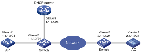
Configuration procedures
1. Configure the DHCP server:
# Enable the DHCP service.
<DHCP server> system-view
[DHCP server] dhcp enable
# Configure DHCP address pool 1.
[DHCP server] dhcp server ip-pool 1
[DHCP server-dhcp-pool-1] network 1.1.1.0 mask 255.255.255.0
# Configure Option 43 to specify the IP address of the AC in address pool 0. The right-most bytes 02010102 (2.1.1.2) represents the IP address of the AC.
[DHCP server-dhcp-pool-1] option 43 ip-address hex 800700000102010102
[DHCP Server-dhcp-pool-1] gateway-list 1.1.1.3
[DHCP Server-dhcp-pool-1] quit
[DHCP Server] quit
2. Configure the AC:
# Set the IP address of VLAN-interface 1 on the AC to 2.1.1.2/24.
[AC] interface vlan-interface 1
[AC-Vlan-interface1] ip address 2.1.1.2 24
[AC-Vlan-interface1] quit
# Configure a default route with next hop 2.1.1.1.
[AC] ip route-static 0.0.0.0 0 2.1.1.1
# Enable auto AP.
[AC] wlan auto-ap enable
Verifying the configuration
# Verify that the AP has established a CAPWAP tunnel with the AC.
[AC] display wlan ap name 0011-2200-0101 verbose
AP name : 0011-2200-0101
AP ID : 1
AP group name : default-group
State : Run
Backup type : Master
Online time : 0 days 1 hours 25 minutes 12 seconds
System up time : 0 days 2 hours 22 minutes 12 seconds
Model : WA536-WW
Region code : CN
Region code lock : Disable
Serial ID : 219801A1NQB117012935
MAC address : 0011-2200-0101
IP address : 1.1.1.2
UDP control port number : 18313
UDP data port number : N/A
H/W version : Ver.C
S/W version : R2206P02
Boot version : 1.01
USB state : N/A
Power Level : N/A
PowerInfo : N/A
Description : wtp1
Priority : 4
Echo interval : 10 seconds
Echo count : 3 counts
Keepalive interval : 10 seconds
Statistics report interval : 50 seconds
Fragment size (data) : 1500
Fragment size (control) : 1450
MAC type : Local MAC & Split MAC
Tunnel mode : Local Bridging & 802.3 Frame & Native Frame
Discovery type : DHCP
Retransmission count : 3
Retransmission interval : 5 seconds
Firmware upgrade : Enabled
Sent control packets : 1
Received control packets : 1
Echo requests : 147
Lost echo responses : 0
Average echo delay : 3
Last reboot reason : User soft reboot
Latest IP address : 10.1.0.2
Tunnel down reason : Request wait timer expired
Connection count : 1
Backup Ipv4 : Not configured
Backup Ipv6 : Not configured
Tunnel encryption : Disabled
LED mode : Normal
Remote configuration : Enabled
Radio 1:
Basic BSSID : 7848-59f6-3940
Admin state : Up
Radio type : 802.11ac
Antenna type : internal
Client dot11ac-only : Disabled
Client dot11n-only : Disabled
Channel band-width : 20/40/80MHz
Active band-width : 20/40/80MHz
Secondary channel offset : SCB
Short GI for 20MHz : Supported
Short GI for 40MHz : Supported
Short GI for 80MHz : Supported
Short GI for 160MHz : Not supported
A-MSDU : Enabled
A-MPDU : Enabled
LDPC : Not Supported
STBC : Supported
Operational VHT-MCS Set:
Mandatory : Not configured
Supported : NSS1 0,1,2,3,4,5,6,7,8,9
NSS2 0,1,2,3,4,5,6,7,8,9
Multicast : Not configured
Operational HT MCS Set:
Mandatory : Not configured
Supported : 0, 1, 2, 3, 4, 5, 6, 7, 8, 9,
10, 11, 12, 13, 14, 15
Multicast : Not configured
Channel : 44(auto)
Channel usage(%) : 15
Max power : 20 dBm
Operational rate:
Mandatory : 6, 12, 24 Mbps
Multicast : Auto
Supported : 9, 18, 36, 48, 54 Mbps
Disabled : Not configured
Distance : 1 km
ANI : Enabled
Fragmentation threshold : 2346 bytes
Beacon interval : 100 TU
Protection threshold : 2346 bytes
Long retry threshold : 4
Short retry threshold : 7
Maximum rx duration : 2000 ms
Noise Floor : -102 dBm
Protection mode : cts-to-self
MU-TxBF : Enabled
SU-TxBF : Enabled
Continuous mode : N/A
HT protection mode : No protection
Radio 2:
Basic BSSID : 7848-59f6-3950
Admin state : Down
Radio type : 802.11ac
Antenna type : internal
Client dot11ac-only : Disabled
Client dot11n-only : Disabled
Channel band-width : 20/40/80MHz
Active band-width : 20/40/80MHz
Secondary channel offset : SCN
Short GI for 20MHz : Supported
Short GI for 40MHz : Supported
Short GI for 80MHz : Supported
Short GI for 160MHz : Not supported
A-MSDU : Enabled
A-MPDU : Enabled
LDPC : Not Supported
STBC : Supported
Operational HT MCS Set:
Mandatory : Not configured
Supported : NSS1 0,1,2,3,4,5,6,7,8,9
NSS2 0,1,2,3,4,5,6,7,8,9
Multicast : Not configured
Operational HT MCS Set:
Mandatory : Not configured
Supported : 0, 1, 2, 3, 4, 5, 6, 7, 8, 9,
10, 11, 12, 13, 14, 15
Multicast : Not configured
Channel : 149(auto)
Channel usage(%) : 0
Max power : 20 dBm
Operational rate:
Mandatory : 6, 12, 24 Mbps
Multicast : Auto
Supported : 9, 18, 36, 48, 54 Mbps
Disabled : Not configured
Distance : 1 km
ANI : Enabled
Fragmentation threshold : 2346 bytes
Beacon interval : 100 TU
Protection threshold : 2346 bytes
Long retry threshold : 4
Short retry threshold : 7
Maximum rx duration : 2000 ms
Noise floor : 0 dBm
Protection mode : cts-to-self
MU-TxBF : Enabled
SU-TxBF : Enabled
Continuous mode : N/A
HT protection mode : No protection
Radio 3:
Basic BSSID : N/A
Admin state : Down
Radio type : 802.11n(2.4GHz)
Antenna type : internal
Client dot11n-only : Disabled
Channel band-width : 20MHz
Active band-width : 20MHz
Secondary channel offset : SCN
Short GI for 20MHz : Supported
Short GI for 40MHz : Supported
A-MSDU : Enabled
A-MPDU : Enabled
LDPC : Not Supported
STBC : Supported
Operational HT MCS Set:
Mandatory : Not configured
Supported : 0, 1, 2, 3, 4, 5, 6, 7, 8, 9,
10, 11, 12, 13, 14, 15
Multicast : Not configured
Channel : 6(auto)
Channel usage(%) : 0
Max power : 20 dBm
Preamble type : Short
Operational rate:
Mandatory : 1, 2, 5.5, 11 Mbps
Multicast : Auto
Supported : 6, 9, 12, 18, 24, 36, 48, 54 Mbps
Disabled : Not configured
Distance : 1 km
ANI : Enabled
Fragmentation threshold : 2346 bytes
Beacon interval : 100 TU
Protection threshold : 2346 bytes
Long retry threshold : 4
Short retry threshold : 7
Maximum rx duration : 2000 ms
Noise floor : 0 dBm
Protection mode : cts-to-self
Continuous mode : N/A
HT protection mode : No protection
AP group configuration example
Network requirements
As shown in Figure 7, configure AP groups and add AP 1 to AP group group1, and AP 2, AP 3, and AP 4 to AP group group2.
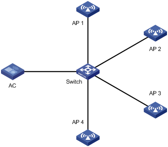
Configuration procedure
1. Configure APs to obtain their IP addresses and the AC IP address from the DHCP server. (Details not shown.)
2. Configure manual APs. (Details not shown.)
3. Configure AP groups:
# Create AP group group1.
[AC] wlan ap-group group1
# Add AP 1 to AP group group1.
[AC-wlan-ap-group-group1] ap ap1
[AC-wlan-ap-group-group1] quit
# Create AP group group2.
# Add AP 2, AP 3, and AP 4 to AP group group2.
[AC-wlan-ap-group-group2] ap ap2 ap3 ap4
[AC-wlan-ap-group-group2] quit
[AC] quit
Verifying the configuration
# Verify that AP 1 is in AP group group1, and AP 2, AP 3, and AP 4 are in AP group group2.
[AC-wlan-ap-group-group2] display wlan ap-group
Total number of AP groups: 3
AP group name : default-group
Description : Not configured
AP model : Not configured
APs : Not configured
AP group name : group1
Description : Not configured
AP model : WA536-WW
AP grouping rules:
AP name : ap1
Serial ID : Not configured
MAC address : Not configured
IPv4 address : Not configured
IPv6 address : Not configured
APs : ap1 (AP name)
AP group name : group2
Description : Not configured
AP model : WA536-WW
AP grouping rules:
AP name : ap2, ap3, ap4
Serial ID : Not configured
MAC address : Not configured
IPv4 address : Not configured
IPv6 address : Not configured
APs : ap2 (AP name), ap3 (AP name), ap4 (AP name)
Configuring radio management
Overview
Radio frequency (RF) is a rate of electrical oscillation in the range of around 300 KHz to 300 GHz. WLAN uses the 2.4 GHz band (2.4 GHz to 2.4835 GHz) and 5 GHz band (5.150 GHz to 5.350 GHz and 5.725 GHz to 5.850 GHz) radio frequencies as the transmission media.
The term "radio frequency" or its abbreviation "RF" is also used as a synonym for "radio" in wireless communication.
Radio mode
Table 2 provides a comparison of these radio modes.
Table 2 802.11 standards comparison
|
IEEE standard |
Frequency band |
Maximum rate |
Indoor coverage |
Outdoor coverage |
|
||||
|
802.11a |
5 GHz |
54 Mbps |
About 50 meters (164.04 ft) |
About 100 meters (328.08 ft) |
|
||||
|
802.11b |
2.4 GHz |
11 Mbps |
About 300 meters (984.25 ft) |
About 600 meters (1968.50 ft) |
|
||||
|
802.11g |
2.4 GHz |
54 Mbps |
About 300 meters (984.25 ft) |
About 600 meters (1968.50 ft) |
|
||||
|
802.11n |
2.4 GHz or 5 GHz |
600 Mbps |
About 300 meters (984.25 ft) |
About 600 meters (1968.50 ft) |
|
||||
|
802.11ac |
5 GHz |
6900 Mbps |
About 30 meters (98.43 ft) |
About 60 meters (196.85 ft) |
|
||||
|
802.11gac |
2.4 GHz |
1600 Mbps |
About 100 meters (328.08 ft) |
About 200 meters (656.17 ft) |
|||||
|
|
NOTE: · 802.11g, 802.11n, and 802.11ac are backward compatible. · The term "802.11ac" in this document includes 802.11gac unless otherwise specified. |
Channel
A channel is a range of frequencies with a specific bandwidth. There are 14 channels designated in the 2.4 GHz band. The bandwidth for each channel is 20 MHz and each two channels are spaced 5 MHz apart. Among the 14 channels, four groups of non-overlapping channels exist and the most commonly used one contains channels 1, 6, and 11.
The 5 GHz band can provide higher rates and is more immune to interferences. There are 24 non-overlapping channels designated in the 5 GHz band. The channels are spaced 20 MHz apart with a bandwidth of 20 MHz.
Transmit power
Transmit power reflects the signal strength of a wireless device. A higher transmit power enables a radio to cover a larger area but it brings more inferences to adjacent devices. The signal strength decreases as the transmission distance increases.
Transmission rate
Transmission rate refers to the speed at which wireless devices transmit traffic. It varies by radio mode and spreading, coding, and modulation schemes. Rates that are supported by different modes of radios are as follows:
· 802.11a—6 Mbps, 9 Mbps, 12 Mbps, 18 Mbps, 24 Mbps, 36 Mbps, 48 Mbps, and 54 Mbps.
· 802.11b—1 Mbps, 2 Mbps, 5.5 Mbps, and 11 Mbps.
· 802.11g—1 Mbps, 2 Mbps, 5.5 Mbps, 6 Mbps, 9 Mbps, 11 Mbps, 12 Mbps, 18 Mbps, 24 Mbps, 36 Mbps, 48 Mbps, and 54 Mbps.
· 802.11n—Rates for 802.11n radios vary by channel bandwidth. For more information, see "MCS."
· 802.11ac—Rates for 802.11ac radios vary by channel bandwidth and number of spatial streams (NSS). For more information, see "VHT-MCS."
MPDU aggregation
A MAC Protocol Data Unit (MPDU) refers to a data frame in 802.11 format. MPDU aggregation aggregates multiple MPDUs into one aggregate MPDU (A-MPDU) to reduce additional information, ACK frames, and Physical Layer Convergence Procedure (PLCP) header overhead. This improves network throughput and channel efficiency.
All MPDUs in an A-MPDU must have the same QoS priority, source address, and destination address.
Figure 8 A-MPDU format
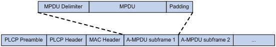
MSDU aggregation
An AP or client encapsulates a MAC Service Data Unit (MSDU) with an Ethernet header and then converts the frame into 802.11 format for forwarding.
MSDU aggregation aggregates multiple MSDUs into one aggregate MSDU (A-MSDU) to reduce PLCP preamble, PLCP header, and MAC header overheads. This improves network throughput and frame forwarding efficiency.
All MSDUs in an A-MSDU must have the same QoS priority, source address, and destination address. When a device receives an A-MSDU, it restores the A-MSDU to multiple MSDUs for processing.
Figure 9 A-MSDU format
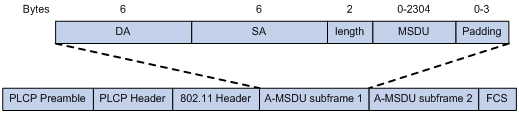
MCS
Modulation and Coding Scheme (MCS) defined in IEEE 802.11n-2009 is a value that determines the modulation, coding, and number of spatial streams. An MCS is identified by an MCS index, which is represented by an integer in the range of 0 to 76. An MCS index is the mapping from MCS to a data rate.
Table 3 through Table 10 show sample MCS parameters for both 20 MHz and 40 MHz.
When the bandwidth mode is 20 MHz, MCS indexes 0 through 15 are mandatory for APs, and MCS indexes 0 through 7 are mandatory for clients.
Table 3 MCS parameters (20 MHz, NSS=1)
|
MCS index |
Number of spatial streams |
Modulation |
Data rate (Mbps) |
|
|
800ns GI |
400ns GI |
|||
|
0 |
1 |
BPSK |
6.5 |
7.2 |
|
1 |
1 |
QPSK |
13.0 |
14.4 |
|
2 |
1 |
QPSK |
19.5 |
21.7 |
|
3 |
1 |
16-QAM |
26.0 |
28.9 |
|
4 |
1 |
16-QAM |
39.0 |
43.3 |
|
5 |
1 |
64-QAM |
52.0 |
57.8 |
|
6 |
1 |
64-QAM |
58.5 |
65.0 |
|
7 |
1 |
64-QAM |
65.0 |
72.2 |
Table 4 MCS parameters (20 MHz, NSS=2)
|
MCS index |
Number of spatial streams |
Modulation |
Data rate (Mbps) |
|
|
800ns GI |
400ns GI |
|||
|
8 |
2 |
BPSK |
13.0 |
14.4 |
|
9 |
2 |
QPSK |
26.0 |
28.9 |
|
10 |
2 |
QPSK |
39.0 |
43.3 |
|
11 |
2 |
16-QAM |
52.0 |
57.8 |
|
12 |
2 |
16-QAM |
78.0 |
86.7 |
|
13 |
2 |
64-QAM |
104.0 |
115.6 |
|
14 |
2 |
64-QAM |
117.0 |
130.0 |
|
15 |
2 |
64-QAM |
130.0 |
144.4 |
Table 5 MCS parameters (20 MHz, NSS=3)
|
MCS index |
Number of spatial streams |
Modulation |
Data rate (Mbps) |
|
|
800ns GI |
400ns GI |
|||
|
16 |
3 |
BPSK |
19.5 |
21.7 |
|
17 |
3 |
QPSK |
39.0 |
43.3 |
|
18 |
3 |
QPSK |
58.5 |
65.0 |
|
19 |
3 |
16-QAM |
78.0 |
86.7 |
|
20 |
3 |
16-QAM |
117.0 |
130.0 |
|
21 |
3 |
64-QAM |
156.0 |
173.3 |
|
22 |
3 |
64-QAM |
175.5 |
195.0 |
|
23 |
3 |
64-QAM |
195.0 |
216.7 |
Table 6 MCS parameters (20 MHz, NSS=4)
|
MCS index |
Number of spatial streams |
Modulation |
Data rate (Mbps) |
|
|
800ns GI |
400ns GI |
|||
|
24 |
4 |
BPSK |
26.0 |
28.9 |
|
25 |
4 |
QPSK |
52.0 |
57.8 |
|
26 |
4 |
QPSK |
78.0 |
86.7 |
|
27 |
4 |
16-QAM |
104.0 |
115.6 |
|
28 |
4 |
16-QAM |
156.0 |
173.3 |
|
29 |
4 |
64-QAM |
208.0 |
231.1 |
|
30 |
4 |
64-QAM |
234.0 |
260.0 |
|
31 |
4 |
64-QAM |
260.0 |
288.9 |
Table 7 MCS parameters (40 MHz, NSS=1)
|
MCS index |
Number of spatial streams |
Modulation |
Data rate (Mbps) |
|
|
800ns GI |
400ns GI |
|||
|
0 |
1 |
BPSK |
13.5 |
15.0 |
|
1 |
1 |
QPSK |
27.0 |
30.0 |
|
2 |
1 |
QPSK |
40.5 |
45.0 |
|
3 |
1 |
16-QAM |
54.0 |
60.0 |
|
4 |
1 |
16-QAM |
81.0 |
90.0 |
|
5 |
1 |
64-QAM |
108.0 |
120.0 |
|
6 |
1 |
64-QAM |
121.5 |
135.0 |
|
7 |
1 |
64-QAM |
135.0 |
150.0 |
Table 8 MCS parameters (40 MHz, NSS=2)
|
MCS index |
Number of spatial streams |
Modulation |
Data rate (Mbps) |
|
|
800ns GI |
400ns GI |
|||
|
8 |
2 |
BPSK |
27.0 |
30.0 |
|
9 |
2 |
QPSK |
54.0 |
60.0 |
|
10 |
2 |
QPSK |
81.0 |
90.0 |
|
11 |
2 |
16-QAM |
108.0 |
120.0 |
|
12 |
2 |
16-QAM |
162.0 |
180.0 |
|
13 |
2 |
64-QAM |
216.0 |
240.0 |
|
14 |
2 |
64-QAM |
243.0 |
270.0 |
|
15 |
2 |
64-QAM |
270.0 |
300.0 |
Table 9 MCS parameters (40 MHz, NSS=3)
|
MCS index |
Number of spatial streams |
Modulation |
Data rate (Mbps) |
|
|
800ns GI |
400ns GI |
|||
|
16 |
3 |
BPSK |
40.5 |
45.0 |
|
17 |
3 |
QPSK |
81.0 |
90.0 |
|
18 |
3 |
QPSK |
121.5 |
135.0 |
|
19 |
3 |
16-QAM |
162.0 |
180.0 |
|
20 |
3 |
16-QAM |
243.0 |
270.0 |
|
21 |
3 |
64-QAM |
324.0 |
360.0 |
|
22 |
3 |
64-QAM |
364.5 |
405.0 |
|
23 |
3 |
64-QAM |
405.0 |
450.0 |
Table 10 MCS parameters (40 MHz, NSS=4)
|
MCS index |
Number of spatial streams |
Modulation |
Data rate (Mbps) |
|
|
800ns GI |
400ns GI |
|||
|
24 |
4 |
BPSK |
54.0 |
60.0 |
|
25 |
4 |
QPSK |
108.0 |
120.0 |
|
26 |
4 |
QPSK |
162.0 |
180.0 |
|
27 |
4 |
16-QAM |
216.0 |
240.0 |
|
28 |
4 |
16-QAM |
324.0 |
360.0 |
|
29 |
4 |
64-QAM |
432.0 |
480.0 |
|
30 |
4 |
64-QAM |
486.0 |
540.0 |
|
31 |
4 |
64-QAM |
540.0 |
600.0 |
MCS indexes are classified into the following types:
· Mandatory MCS indexes—Mandatory MCS indexes for an AP. Clients can associate with an 802.11n AP only when they support the mandatory MCS indexes for the AP.
· Supported MCS indexes—MCS indexes supported by an AP except for the mandatory MCS indexes. Supported MCS indexes allow a client that supports both mandatory and supported MCS indexes to use a higher rate to communicate with the AP.
· Multicast MCS index—MCS index corresponding to the rate at which an AP transmits multicast frames.
|
|
NOTE: · For all the MCS data rate tables, see IEEE 802.11n-2009. · Support for MCS indexes depends on the AP model. |
VHT-MCS
802.11 ac uses Very High Throughput Modulation and Coding Scheme (VHT-MCS) indexes to indicate wireless data rates. A VHT-MCS is identified by a VHT-MCS index, which is represented by an integer in the range of 0 to 9. A VHT-MCS index is the mapping from VHT-MCS to a data rate.
802.11ac supports the 20 MHz, 40 MHz, 80 MHz, and 160 MHz bandwidth modes, and supports a maximum of eight spatial streams. 802.11gac supports the 20 MHz and 40 MHz bandwidth modes.
Table 11 through Table 22 show VHT-MCS parameters that are supported by an AP.
Table 11 VHT-MCS parameters (20 MHz, NSS=1)
|
VHT-MCS index |
Modulation |
Data rate (Mbps) |
|
|
800ns GI |
400ns GI |
||
|
0 |
BPSK |
6.5 |
7.2 |
|
1 |
QPSK |
13.0 |
14.4 |
|
2 |
QPSK |
19.5 |
21.7 |
|
3 |
16-QAM |
26.0 |
28.9 |
|
4 |
16-QAM |
39.0 |
43.3 |
|
5 |
64-QAM |
52.0 |
57.8 |
|
6 |
64-QAM |
58.5 |
65.0 |
|
7 |
64-QAM |
65.0 |
72.2 |
|
8 |
256-QAM |
78.0 |
86.7 |
|
9 |
Not valid |
||
Table 12 VHT-MCS parameters (20 MHz, NSS=2)
|
VHT-MCS index |
Modulation |
Data rate (Mbps) |
|
|
800ns GI |
400ns GI |
||
|
0 |
BPSK |
13.0 |
14.4 |
|
1 |
QPSK |
26.0 |
28.9 |
|
2 |
QPSK |
39.0 |
43.3 |
|
3 |
16-QAM |
52.0 |
57.8 |
|
4 |
16-QAM |
78.0 |
86.7 |
|
5 |
64-QAM |
104.0 |
115.6 |
|
6 |
64-QAM |
117.0 |
130.0 |
|
7 |
64-QAM |
130.0 |
144.4 |
|
8 |
256-QAM |
156.0 |
173.3 |
|
9 |
Not valid |
||
Table 13 VHT-MCS parameters (20 MHz, NSS=3)
|
VHT-MCS index |
Modulation |
Data rate (Mbps) |
|
|
800ns GI |
400ns GI |
||
|
0 |
BPSK |
19.5 |
21.7 |
|
1 |
QPSK |
39.0 |
43.3 |
|
2 |
QPSK |
58.5 |
65.0 |
|
3 |
16-QAM |
78.0 |
86.7 |
|
4 |
16-QAM |
117.0 |
130.0 |
|
5 |
64-QAM |
156.0 |
173.3 |
|
6 |
64-QAM |
175.5 |
195.0 |
|
7 |
64-QAM |
195.0 |
216.7 |
|
8 |
256-QAM |
234.0 |
260.0 |
|
9 |
256-QAM |
260.0 |
288.9 |
Table 14 VHT-MCS parameters (20 MHz, NSS=4)
|
VHT-MCS index |
Modulation |
Data rate (Mbps) |
|
|
800ns GI |
400ns GI |
||
|
0 |
BPSK |
26.0 |
28.9 |
|
1 |
QPSK |
52.0 |
57.8 |
|
2 |
QPSK |
78.0 |
86.7 |
|
3 |
16-QAM |
104.0 |
115.6 |
|
4 |
16-QAM |
156.0 |
173.3 |
|
5 |
64-QAM |
208.0 |
231.1 |
|
6 |
64-QAM |
234.0 |
260.0 |
|
7 |
64-QAM |
260.0 |
288.9 |
|
8 |
256-QAM |
312.0 |
346.7 |
|
9 |
Not valid |
||
Table 15 VHT-MCS parameters (40 MHz, NSS=1)
|
VHT-MCS index |
Modulation |
Data rate (Mbps) |
|
|
800ns GI |
400ns GI |
||
|
0 |
BPSK |
13.5 |
15.0 |
|
1 |
QPSK |
27.0 |
30.0 |
|
2 |
QPSK |
40.5 |
45.0 |
|
3 |
16-QAM |
54.0 |
60.0 |
|
4 |
16-QAM |
81.0 |
90.0 |
|
5 |
64-QAM |
108.0 |
120.0 |
|
6 |
64-QAM |
121.5 |
135.0 |
|
7 |
64-QAM |
135.0 |
150.0 |
|
8 |
256-QAM |
162.0 |
180.0 |
|
9 |
256-QAM |
180.0 |
200.0 |
Table 16 VHT-MCS parameters (40 MHz, NSS=2)
|
VHT-MCS index |
Modulation |
Data rate (Mbps) |
|
|
800ns GI |
400ns GI |
||
|
0 |
BPSK |
27.0 |
30.0 |
|
1 |
QPSK |
54.0 |
60.0 |
|
2 |
QPSK |
81.0 |
90.0 |
|
3 |
16-QAM |
108.0 |
120.0 |
|
4 |
16-QAM |
162.0 |
180.0 |
|
5 |
64-QAM |
216.0 |
240.0 |
|
6 |
64-QAM |
243.0 |
270.0 |
|
7 |
64-QAM |
270.0 |
300.0 |
|
8 |
256-QAM |
324.0 |
360.0 |
|
9 |
256-QAM |
360.0 |
400.0 |
Table 17 VHT-MCS parameters (40 MHz, NSS=3)
|
VHT-MCS index |
Modulation |
Data rate (Mbps) |
|
|
800ns GI |
400ns GI |
||
|
0 |
BPSK |
40.5 |
45.0 |
|
1 |
QPSK |
81.0 |
90.0 |
|
2 |
QPSK |
121.5 |
135.0 |
|
3 |
16-QAM |
162.0 |
180.0 |
|
4 |
16-QAM |
243.0 |
270.0 |
|
5 |
64-QAM |
324.0 |
360.0 |
|
6 |
64-QAM |
364.5 |
405.0 |
|
7 |
64-QAM |
405.0 |
450.0 |
|
8 |
256-QAM |
486.0 |
540.0 |
|
9 |
256-QAM |
540.0 |
600.0 |
Table 18 VHT-MCS parameters(40 MHz, NSS=4)
|
VHT-MCS index |
Modulation |
Data rate (Mbps) |
|
|
800ns GI |
400ns GI |
||
|
0 |
BPSK |
54.0 |
60.0 |
|
1 |
QPSK |
108.0 |
120.0 |
|
2 |
QPSK |
162.0 |
180.0 |
|
3 |
16-QAM |
216.0 |
240.0 |
|
4 |
16-QAM |
324.0 |
360.0 |
|
5 |
64-QAM |
432.0 |
480.0 |
|
6 |
64-QAM |
486.0 |
540.0 |
|
7 |
64-QAM |
540.0 |
600.0 |
|
8 |
256-QAM |
648.0 |
720.0 |
|
9 |
256-QAM |
720.0 |
800.0 |
Table 19 VHT-MCS parameters (80 MHz, NSS=1)
|
VHT-MCS index |
Modulation |
Data rate (Mbps) |
|
|
800ns GI |
400ns GI |
||
|
0 |
BPSK |
29.3 |
32.5 |
|
1 |
QPSK |
58.5 |
65.0 |
|
2 |
QPSK |
87.8 |
97.5 |
|
3 |
16-QAM |
117.0 |
130.0 |
|
4 |
16-QAM |
175.5 |
195.0 |
|
5 |
64-QAM |
234.0 |
260.0 |
|
6 |
64-QAM |
263.0 |
292.5 |
|
7 |
64-QAM |
292.5 |
325.0 |
|
8 |
256-QAM |
351.0 |
390.0 |
|
9 |
256-QAM |
390.0 |
433.3 |
Table 20 VHT-MCS parameters (80 MHz, NSS=2)
|
VHT-MCS index |
Modulation |
Data rate (Mbps) |
|
|
800ns GI |
400ns GI |
||
|
0 |
BPSK |
58.5 |
65.0 |
|
1 |
QPSK |
117.0 |
130.0 |
|
2 |
QPSK |
175.5 |
195.0 |
|
3 |
16-QAM |
234.0 |
260.0 |
|
4 |
16-QAM |
351.0 |
390.0 |
|
5 |
64-QAM |
468.0 |
520.0 |
|
6 |
64-QAM |
526.5 |
585.0 |
|
7 |
64-QAM |
585.0 |
650.0 |
|
8 |
256-QAM |
702.0 |
780.0 |
|
9 |
256-QAM |
780.0 |
866.7 |
Table 21 VHT-MCS parameters (80 MHz, NSS=3)
|
VHT-MCS index |
Modulation |
Data rate (Mbps) |
|
|
800ns GI |
400ns GI |
||
|
0 |
BPSK |
87.8 |
97.5 |
|
1 |
QPSK |
175.5 |
195.0 |
|
2 |
QPSK |
263.3 |
292.5 |
|
3 |
16-QAM |
351.0 |
390.0 |
|
4 |
16-QAM |
526.5 |
585.0 |
|
5 |
64-QAM |
702.0 |
780.0 |
|
6 |
Not valid |
||
|
7 |
64-QAM |
877.5 |
975.0 |
|
8 |
256-QAM |
1053.0 |
1170.0 |
|
9 |
256-QAM |
1170.0 |
1300.0 |
Table 22 VHT-MCS parameters (80 MHz, NSS=4)
|
VHT-MCS index |
Modulation |
Data rate (Mbps) |
|
|
800ns GI |
400ns GI |
||
|
0 |
BPSK |
117.0 |
130.0 |
|
1 |
QPSK |
234.0 |
260.0 |
|
2 |
QPSK |
351.0 |
390.0 |
|
3 |
16-QAM |
468.0 |
520.0 |
|
4 |
16-QAM |
702.0 |
780.0 |
|
5 |
64-QAM |
936.0 |
1040.0 |
|
6 |
64-QAM |
1053.0 |
1170.0 |
|
7 |
64-QAM |
1170.0 |
1300.0 |
|
8 |
256-QAM |
1404.0 |
1560.0 |
|
9 |
256-QAM |
1560.0 |
1733.3 |
802.11ac NSSs are classified into the following types:
· Mandatory NSSs—Mandatory NSSs for an AP. Clients can associate with an 802.11ac AP only when they support the mandatory NSSs for the AP.
· Supported NSSs—NSSs supported by an AP except for the mandatory NSSs. Supported NSSs allow a client that supports both mandatory and supported NSSs to use a higher rate to communicate with the AP.
· Multicast NSS—An AP uses a rate in the VHT-MCS data rate table for the NSS to transmit multicast frames.
|
|
NOTE: · For all the VHT-MCS data rate tables, see IEEE 802.11ac-2013. · Support for VHT-MCS indexes depends on the AP model. |
Configuration restrictions and guidelines
The priorities for the configuration in radio view, AP group radio view, and global configuration view are in descending order.
Configuration task list
Enabling or disabling radios
Enabling or disabling all radios
|
|
CAUTION: Disabling all radios terminates wireless services. Use it with caution. |
This feature only takes effect on manual APs and online auto APs.
To enable or disable all radios:
|
Step |
Command |
Remarks |
|
1. Enter system view. |
system-view |
N/A |
|
2. Enable or disable all radios. |
wlan radio { enable | disable } |
By default, radios are disabled unless they are already enabled in radio view or AP group radio view. |
Enabling or disabling a radio in radio view
|
Step |
Command |
Remarks |
|
1. Enter system view. |
system-view |
N/A |
|
2. Create an AP and enter AP view. |
wlan ap ap-name [ model model-name ] |
By default, no AP is created. You must specify the name and model when you create an AP. |
|
3. Enter radio view. |
radio radio-id |
N/A |
|
4. Enable or disable the radio. |
radio { enable | disable } |
By default, a radio is enabled if the wlan radio enable command is executed in system view. If the wlan radio enable command is not executed in system view, a radio uses the configuration in AP group radio view. |
Enabling or disabling a radio in AP group radio view
|
Step |
Command |
Remarks |
|
1. Enter system view. |
system-view |
N/A |
|
2. Create an AP group and enter AP group view. |
wlan ap-group group-name |
By default, the default AP group default-group exists and it cannot be deleted. |
|
3. Enter AP model view. |
ap-model ap-model |
N/A |
|
4. Enter radio view. |
radio radio-id |
N/A |
|
5. Enable or disable the radio. |
radio { enable | disable } |
By default, a radio is disabled unless it is already enabled by using the wlan radio enable command in system view. |
Specifying a radio mode
|
|
CAUTION: Modifying the radio mode logs off all associated clients. |
Support for channels and transmit powers depends on the radio mode. When you change the mode of a radio, the system automatically adjusts the channel and power parameters for the radio.
When you change the radio mode in AP group radio view, the default settings for the commands related to the radio mode are restored.
Specifying a radio mode in radio view
|
Step |
Command |
Remarks |
|
1. Enter system view. |
system-view |
N/A |
|
2. Create an AP and enter AP view. |
wlan ap ap-name [ model model-name ] |
By default, no AP is created. You must specify the name and model when you create an AP. |
|
3. Enter radio view. |
radio radio-id |
N/A |
|
4. Specify a radio mode. |
type { dot11a | dot11ac | dot11an | dot11b | dot11g | dot11gac | dot11gn } |
By default, the radio uses the configuration in AP group view. |
Specifying a radio mode in AP group radio view
|
Step |
Command |
Remarks |
|
1. Enter system view. |
system-view |
N/A |
|
2. Create an AP group and enter AP group view. |
wlan ap-group group-name |
By default, the default AP group default-group exists and it cannot be deleted. |
|
3. Enter AP model view. |
ap-model ap-model |
N/A |
|
4. Enter radio view. |
radio radio-id |
N/A |
|
5. Specify a radio mode. |
type { dot11a | dot11ac | dot11an | dot11b | dot11g | dot11gac | dot11gn } |
The default setting for this command varies by AP model. |
Configuring basic radio functions
Specifying a working channel
Perform this task to reduce interferences from both wireless and non-wireless devices.
You can manually specify a channel or configure the system to automatically select a channel for a radio.
When radar signals are detected on the working channel of a radio, either of the following cases occurs:
· If the channel is a manually specified channel, the radio changes its channel, and switches back to the specified channel after 30 minutes and then starts the quiet timer. If no radar signals are detected within the quiet time, the radio starts to use the channel. If radar signals are detected within the quiet time, the radio changes its channel.
· If the channel is an automatically assigned channel, the radio changes its channel.
Specifying a working channel in radio view
|
Step |
Command |
Remarks |
|
1. Enter system view. |
system-view |
N/A |
|
2. Create an AP and enter AP view. |
wlan ap ap-name [ model model-name ] |
By default, no AP is created. You must specify the name and model when you create an AP. |
|
3. Enter radio view. |
radio radio-id |
N/A |
|
4. Specify a working channel. |
channel { channel-number | auto { lock | unlock } } |
By default, the radio uses the configuration in AP group view. |
Specifying a working channel in AP group radio view
|
Step |
Command |
Remarks |
|
1. Enter system view. |
system-view |
N/A |
|
2. Create an AP group and enter AP group view. |
wlan ap-group group-name |
By default, the default AP group default-group exists and it cannot be deleted. |
|
3. Enter AP model view. |
ap-model ap-model |
N/A |
|
4. Enter radio view. |
radio radio-id |
N/A |
|
5. Specify a working channel. |
channel { channel-number | auto { lock | unlock } } |
By default, the AC automatically selects a channel for the radio and does not lock the channel. |
Configuring 2.4 GHz radios to use the European channel gap for auto channel selection
By default, 2.4 GHz radios use non-European channel gap 5 to automatically select channels 1, 6, and 11. You can use this feature to enable the radios to use European channel gap 6 to automatically select channels 1, 7, and 13.
To configure 2.4 GHz radios to use the European channel gap for auto channel selection:
|
Step |
Command |
Remarks |
|
1. Enter system view. |
system-view |
|
|
2. Enter global configuration view. |
wlan global-configuration |
N/A |
|
3. Configure 2.4 GHz radios to use the European channel gap for auto channel selection. |
auto-channel european-gap enable |
By default, 2.4 GHz radios use the non-European channel gap for auto channel selection. |
Configuring the channel selection blacklist or whitelist
Perform this task for an AP to not select channels in the blacklist or to select only channels in the whitelist in automatic channel selection. You cannot configure both the channel selection blacklist and whitelist for the same AP.
Configuring the channel selection blacklist or whitelist in radio view
|
Step |
Command |
Remarks |
|
1. Enter system view. |
system-view |
N/A |
|
2. Enter AP view. |
wlan ap ap-name [ model model-name ] |
N/A |
|
3. Enter radio view. |
radio radio-id |
N/A |
|
4. Add the specified channels to the channel selection blacklist or whitelist. |
channel auto-select { blacklist | whitelist } channel-number |
By default, a radio uses the configuration in AP group view. |
Configuring the channel selection blacklist or whitelist in AP group radio view
|
Step |
Command |
Remarks |
|
5. Enter system view. |
system-view |
N/A |
|
6. Enter AP group view. |
wlan ap-group group-name |
N/A |
|
7. Enter AP model view. |
ap-model ap-model |
N/A |
|
8. Enter radio view. |
radio radio-id |
N/A |
|
9. Add the specified channels to the channel selection blacklist or whitelist. |
channel auto-select { blacklist | whitelist } channel-number |
By default, no channel selection blacklist or the whitelist exists. |
Setting the antenna type
|
|
NOTE: Antenna types supported by an AP vary by device model. |
If an AP uses a third-party antenna, you must set the antenna type to the type of the antenna that the AP uses.
The antenna gain automatically changes after you set the antenna type to ensure that the transmit power is within the correct range.
Setting the antenna type in radio view
|
Step |
Command |
Remarks |
|
1. Enter system view. |
system-view |
N/A |
|
2. Create an AP and enter AP view. |
wlan ap ap-name [ model model-name ] |
By default, no AP is created. You must specify the name and model when you create an AP. |
|
3. Enter radio view. |
radio radio-id |
N/A |
|
4. Set the antenna type. |
antenna type antenna-type |
By default, the radio uses the configuration in AP group view. |
Setting the antenna type in AP group radio view
|
Step |
Command |
Remarks |
|
1. Enter system view. |
system-view |
N/A |
|
2. Create an AP group and enter AP group view. |
wlan ap-group group-name |
By default, the default AP group default-group exists and it cannot be deleted. |
|
3. Enter AP model view. |
ap-model ap-model |
N/A |
|
4. Enter radio view. |
radio radio-id |
N/A |
|
5. Set the antenna type. |
antenna type antenna-type |
The default antenna type for an AP varies by device model. |
Setting the antenna gain
|
|
IMPORTANT: This feature is available only when an AP uses a third-party antenna. |
Effective Isotropic Radiated Power (EIRP) is the actual transmit power of an antenna, and it is the sum of the antenna gain and the maximum transmit power of the radio.
If an AP uses a third-party antenna, you must set the antenna gain to the gain of the antenna that the AP uses.
Setting the antenna gain in radio view
|
Step |
Command |
Remarks |
|
1. Enter system view. |
system-view |
N/A |
|
2. Create an AP and enter AP view. |
wlan ap ap-name [ model model-name ] |
By default, no AP is created. You must specify the name and model when you create an AP. |
|
3. Enter radio view. |
radio radio-id |
N/A |
|
4. Set the antenna gain. |
custom-antenna gain antenna-gain |
By default, the radio uses the configuration in AP group view. |
Setting the antenna gain in AP group radio view
|
Step |
Command |
Remarks |
|
1. Enter system view. |
system-view |
N/A |
|
2. Create an AP group and enter AP group view. |
wlan ap-group group-name |
By default, the default AP group default-group exists and it cannot be deleted. |
|
3. Enter AP model view. |
ap-model ap-model |
N/A |
|
4. Enter radio view. |
radio radio-id |
N/A |
|
5. Set the antenna gain. |
custom-antenna gain antenna-gain |
By default, the antenna gain is 0 dBi. |
Setting the maximum transmit power
Make sure the maximum transmit power is within the transmit power range supported by a radio. The transmit power range supported by a radio varies by country code, channel, AP model, radio mode, antenna type, and bandwidth mode. If you change these attributes for a radio after you set the maximum transmit power, the configured maximum transmit power might be out of the supported transmit power range. If this happens, the system automatically adjusts the maximum transmit power to a valid value.
If you enable power lock, the locked power becomes the maximum transmit power. For more information about power lock, see "Configuring power lock."
Setting the maximum transmit power in radio view
|
Step |
Command |
Remarks |
|
1. Enter system view. |
system-view |
N/A |
|
2. Create an AP and enter AP view. |
wlan ap ap-name [ model model-name ] |
By default, no AP is created. You must specify the name and model when you create an AP. |
|
3. Enter radio view. |
radio radio-id |
N/A |
|
4. Set the maximum transmit power. |
max-power radio-power |
By default, the radio uses the configuration in AP group view. |
Setting the maximum transmit power in AP group radio view
|
Step |
Command |
Remarks |
|
1. Enter system view. |
system-view |
N/A |
|
2. Create an AP group and enter AP group view. |
wlan ap-group group-name |
By default, the default AP group default-group exists and it cannot be deleted. |
|
3. Enter AP model view. |
ap-model ap-model |
N/A |
|
4. Enter radio view. |
radio radio-id |
N/A |
|
5. Set the maximum transmit power. |
max-power radio-power |
By default, the radio uses the supported maximum transmit power. |
Configuring power lock
If you enable power lock, the current power is locked and becomes the maximum transmit power. The locked power still takes effect after the AC restarts.
If a radio enabled with power lock switches to a new channel that provides lower power than the locked power, the maximum power supported by the new channel takes effect.
Configuring power lock in radio view
|
Step |
Command |
Remarks |
|
1. Enter system view. |
system-view |
N/A |
|
2. Create an AP and enter AP view. |
wlan ap ap-name [ model model-name ] |
By default, no AP is created. You must specify the name and model when you create an AP. |
|
3. Enter radio view. |
radio radio-id |
N/A |
|
4. Configure power lock. |
power-lock { disable | enable } |
By default, the radio uses the configuration in AP group view. |
Configuring power lock in AP group radio view
|
Step |
Command |
Remarks |
|
1. Enter system view. |
system-view |
N/A |
|
2. Create an AP group and enter AP group view. |
wlan ap-group group-name |
By default, the default AP group default-group exists and it cannot be deleted. |
|
3. Enter AP model view. |
ap-model ap-model |
N/A |
|
4. Enter radio view. |
radio radio-id |
N/A |
|
5. Configure power lock. |
power-lock { disable | enable } |
By default, power lock is disabled. |
Setting transmission rates
Transmission rates are classified into the following types:
· Prohibited rates—Rates that cannot be used by an AP.
· Mandatory rates—Rates that the clients must support to associate with an AP.
· Supported rates—Rates that an AP supports. After a client associates with an AP, the client can select a higher rate from the supported rates to communicate with the AP. The AP automatically decreases the transmission rate when great interference, retransmission, or packet dropping is detected and increases the rate when a little interference, retransmission, or packet dropping is detected.
· Multicast rate—Rate at which an AP transmits multicasts and broadcasts. The multicast rate must be selected from the mandatory rates.
Setting the transmission rates in radio view
|
Step |
Command |
Remarks |
|
1. Enter system view. |
system-view |
N/A |
|
2. Create an AP and enter AP view. |
wlan ap ap-name [ model model-name ] |
By default, no AP is created. You must specify the name and model when you create an AP. |
|
3. Enter radio view. |
radio radio-id |
N/A |
|
4. Set the transmission rates for the radio. |
rate { multicast { auto | rate-value } | { disabled | mandatory | supported } rate-value } |
By default, the radio uses the configuration in AP group view. |
Setting the transmission rates in AP group radio view
|
Step |
Command |
Remarks |
|
1. Enter system view. |
system-view |
N/A |
|
2. Create an AP group and enter AP group view. |
wlan ap-group group-name |
By default, the default AP group default-group exists and it cannot be deleted. |
|
3. Enter AP model view. |
ap-model ap-model |
N/A |
|
4. Enter radio view. |
radio radio-id |
N/A |
|
5. Set the transmission rates for the radio. |
rate { multicast { auto | rate-value } | { disabled | mandatory | supported } rate-value } |
The default settings are as follows: · 802.11a/802.11an/802.11ac radios: ? Prohibited rates—None. ? Mandatory rates—6, 12, and 24. ? Multicast rate—Selected from the mandatory rates. ? Supported rates—9, 18, 36, 48, and 54. · 802.11b radios: ? Prohibited rates—None. ? Mandatory rates—1 and 2. ? Multicast rate—Selected from the mandatory rates. ? Supported rates—5.5, and 11. · 802.11g/802.11gn/802.11gac radios: ? Prohibited rates—None. ? Mandatory rates—1, 2, 5.5, and 11. ? Multicast rate—Selected from the mandatory rates. ? Supported rates—6, 9, 12, 18, 24, 36, 48, and 54. |
Setting the preamble type
|
|
IMPORTANT: This feature is applicable only to 802.11b, 802.11g, and 802.11gn radios. |
A preamble is a set of bits in a packet header to synchronize transmission signals between sender and receiver. A short preamble improves network performance and a long preamble ensures compatibility with all wireless devices of early models.
Setting the preamble type in radio view
|
Step |
Command |
Remarks |
|
1. Enter system view. |
system-view |
N/A |
|
2. Create an AP and enter AP view. |
wlan ap ap-name [ model model-name ] |
By default, no AP is created. You must specify the name and model when you create an AP. |
|
3. Enter radio view. |
radio radio-id |
N/A |
|
4. Set the preamble type. |
preamble { long | short } |
By default, the radio uses the configuration in AP group view. |
Setting the preamble type in AP group radio view
|
Step |
Command |
Remarks |
|
1. Enter system view. |
system-view |
N/A |
|
2. Create an AP group and enter AP group view. |
wlan ap-group group-name |
By default, the default AP group default-group exists and it cannot be deleted. |
|
3. Enter AP model view. |
ap-model ap-model |
N/A |
|
4. Enter radio view. |
radio radio-id |
N/A |
|
5. Set the preamble type. |
preamble { long | short } |
By default, a short preamble is used. |
Setting the maximum transmission distance
The strength of wireless signals gradually degrades as the transmission distance increases. The maximum transmission distance of wireless signals depends on the surrounding environment and on whether an external antenna is used.
· Without an external antenna—About 300 meters (984.25 ft).
· With an external antenna—30 km (18.64 miles) to 50 km (31.07 miles).
· In an area with obstacles—35 m (114.83 ft) to 50 m (164.04 ft).
Setting the maximum transmission distance in radio view
|
Step |
Command |
Remarks |
|
1. Enter system view. |
system-view |
N/A |
|
2. Create an AP and enter AP view. |
wlan ap ap-name [ model model-name ] |
By default, no AP is created. You must specify the name and model when you create an AP. |
|
3. Enter radio view. |
radio radio-id |
N/A |
|
4. Set the maximum transmission distance. |
distance distance |
By default, the radio uses the configuration in AP group view. |
Setting the maximum transmission distance in AP group radio view
|
Step |
Command |
Remarks |
|
1. Enter system view. |
system-view |
N/A |
|
2. Create an AP group and enter AP group view. |
wlan ap-group group-name |
By default, the default AP group default-group exists and it cannot be deleted. |
|
3. Enter AP model view. |
ap-model ap-model |
N/A |
|
4. Enter radio view. |
radio radio-id |
N/A |
|
5. Set the maximum transmission distance. |
distance distance |
By default, the maximum transmission distance is 1 km (0.62 miles). |
Setting the beacon interval
Perform this task to enable an AP to broadcast beacon frames at the specified interval. A small beacon interval enables clients to easily detect the AP but consumes more system resources.
Setting the beacon interval in radio view
|
Step |
Command |
Remarks |
|
1. Enter system view. |
system-view |
N/A |
|
2. Create an AP and enter AP view. |
wlan ap ap-name [ model model-name ] |
By default, no AP is created. You must specify the name and model when you create an AP. |
|
3. Enter radio view. |
radio radio-id |
N/A |
|
4. Set the beacon interval. |
beacon-interval interval |
By default, the radio uses the configuration in AP group view. |
Setting the beacon interval in AP group radio view
|
Step |
Command |
Remarks |
|
1. Enter system view. |
system-view |
N/A |
|
2. Create an AP group and enter AP group view. |
wlan ap-group group-name |
By default, the default AP group default-group exists and it cannot be deleted. |
|
3. Enter AP model view. |
ap-model ap-model |
N/A |
|
4. Enter radio view. |
radio radio-id |
N/A |
|
5. Set the beacon interval. |
beacon-interval interval |
By default, the beacon interval is 100 TU. |
Setting the DTIM interval
An AP periodically broadcasts a beacon compliant with the Delivery Traffic Indication Map (DTIM). After the AP broadcasts the beacon, it sends buffered broadcast and multicast frames based on the value of the DTIM interval. For example, if you set the DTIM interval to 5, the AP sends buffered broadcast and multicast frames every five beacon frames.
Setting the DTIM interval in radio view
|
Step |
Command |
Remarks |
|
1. Enter system view. |
system-view |
N/A |
|
2. Create an AP and enter AP view. |
wlan ap ap-name [ model model-name ] |
By default, no AP is created. You must specify the name and model when you create an AP. |
|
3. Enter radio view. |
radio radio-id |
N/A |
|
4. Set the DTIM interval. |
dtim counter |
By default, the radio uses the configuration in AP group view. |
Setting the DTIM interval in AP group radio view
|
Step |
Command |
Remarks |
|
1. Enter system view. |
system-view |
N/A |
|
2. Create an AP group and enter AP group view. |
wlan ap-group group-name |
By default, the default AP group default-group exists and it cannot be deleted. |
|
3. Enter AP model view. |
ap-model ap-model |
N/A |
|
4. Enter radio view. |
radio radio-id |
N/A |
|
5. Set the DTIM interval. |
dtim counter |
By default, the DTIM interval is 1. |
Setting the maximum number of clients that can associate with an AP
When the maximum number of clients is reached on an AP, the AP stops accepting new clients. This prevents the AP from being overloaded.
Setting the maximum number of clients that can associate with an AP in radio view
|
Step |
Command |
Remarks |
|
1. Enter system view. |
system-view |
N/A |
|
2. Create an AP and enter AP view. |
wlan ap ap-name [ model model-name ] |
By default, no AP is created. You must specify the name and model when you create an AP. |
|
3. Enter radio view. |
radio radio-id |
N/A |
|
4. Set the maximum number of clients that can associate with the AP. |
client max-count max-number |
By default, the radio uses the configuration in AP group view. |
Setting the maximum number of clients that can associate with an AP in AP group radio view
|
Step |
Command |
Remarks |
|
1. Enter system view. |
system-view |
N/A |
|
2. Create an AP group and enter AP group view. |
wlan ap-group group-name |
By default, the default AP group default-group exists and it cannot be deleted. |
|
3. Enter AP model view. |
ap-model ap-model |
N/A |
|
4. Enter radio view. |
radio radio-id |
N/A |
|
5. Set the maximum number of clients that can associate with the AP. |
client max-count max-number |
By default, no limit is set for the number of clients that can associate with an AP. |
Configuring 802.11b client access
To reduce the impact of low-speed 802.11b clients and speed up wireless data transmission, you can enable an 802.11g, 802.11gn, or 802.11gac radio to prohibit access for 802.11b clients.
Configuring 802.11b client access in radio view
|
Step |
Command |
Remarks |
|
1. Enter system view. |
system-view |
N/A |
|
2. Create an AP and enter AP view. |
wlan ap ap-name [ model model-name ] |
By default, no AP is created. You must specify the name and model when you create an AP. |
|
3. Enter radio view. |
radio radio-id |
N/A |
|
4. Configure 802.11b client access. |
client dot11b-forbidden { disable | enable } |
By default, the radio uses the configuration in AP group view. |
Configuring 802.11b client access in AP group radio view
|
Step |
Command |
Remarks |
|
1. Enter system view. |
system-view |
N/A |
|
2. Create an AP group and enter AP group view. |
wlan ap-group group-name |
By default, the default AP group default-group exists and it cannot be deleted. |
|
3. Enter AP model view. |
ap-model ap-model |
N/A |
|
4. Enter radio view. |
radio radio-id |
N/A |
|
5. Configure 802.11b client access. |
client dot11b-forbidden { disable | enable } |
By default, the radio accepts 802.11b clients. |
Configuring ANI
Adaptive Noise Immunity (ANI) enables the device to adjust the anti-noise level based on the environment to reduce the interference from the surrounding environment.
Configuring ANI in radio view
|
Step |
Command |
Remarks |
|
1. Enter system view. |
system-view |
N/A |
|
2. Create an AP and enter AP view. |
wlan ap ap-name [ model model-name ] |
By default, no AP is created. You must specify the name and model when you create an AP. |
|
3. Enter radio view. |
radio radio-id |
N/A |
|
4. Configure ANI. |
ani { disable | enable } |
By default, the radio uses the configuration in AP group view. |
Configuring ANI in AP group radio view
|
Step |
Command |
Remarks |
|
1. Enter system view. |
system-view |
N/A |
|
2. Create an AP group and enter AP group view. |
wlan ap-group group-name |
By default, the default AP group default-group exists and it cannot be deleted. |
|
3. Enter AP model view. |
ap-model ap-model |
N/A |
|
4. Enter radio view. |
radio radio-id |
N/A |
|
5. Configure ANI. |
ani { disable | enable } |
By default, ANI is enabled. |
Specifying a collision avoidance mode
Wireless devices operate in half duplex mode and cannot send and receive data simultaneously. 802.11 allows wireless devices to send Request to Send (RTS) or Clear to Send (CTS) packets to avoid collision.
You can specify either of the following collision avoidance modes for an AP:
· RTS/CTS—An AP sends an RTS packet to a client before sending data to the client. After receiving the RTS packet, the client sends a CTS packet to the AP. The AP begins to send data after receiving the CTS packet, and other devices that detect the RTS or CTS packet do not send data within a specific time period.
|
|
NOTE: 802.11b radios support only the RTS/CTS mode. |
· CTS-to-self—An AP sends a CTS packet with its own MAC address as the destination MAC address before sending data to a client. After receiving the CTS-to-self packet, the AP begins to send data, and other devices that detect the CTS-to-self packet do not send data within a specific time period. The CTS-to-self mode reduces the transmission time but might result in hidden node problems.
To ensure wireless resource efficiency, collision avoidance takes effect only when the following conditions are met:
· The packet to be sent is longer than the RTS threshold 2346 bytes.
· 802.11g or 802.11n protection is enabled. For more information about 802.11g or 802.11n protection, see "Configuring 802.11g protection" and "Configuring 802.11n protection."
Specifying a collision avoidance mode in radio view
|
Step |
Command |
Remarks |
|
1. Enter system view. |
system-view |
N/A |
|
2. Enter AP view. |
wlan ap ap-name [ model model-name ] |
N/A |
|
3. Enter radio view. |
radio radio-id |
N/A |
|
4. Specify a collision avoidance mode. |
protection-mode { cts-to-self | rts-cts } |
By default, the radio uses the configuration in AP group view. |
Specifying a collision avoidance mode in AP group radio view
|
Step |
Command |
Remarks |
|
1. Enter system view. |
system-view |
N/A |
|
2. Enter AP group view. |
wlan ap-group group-name |
N/A |
|
3. Enter AP model view. |
ap-model ap-model |
N/A |
|
4. Enter radio view. |
radio radio-id |
N/A |
|
5. Specify a collision avoidance mode. |
protection-mode { cts-to-self | rts-cts } |
By default, the CTS-to-self mode is used. |
Setting the RTS threshold
802.11 allows wireless devices to send Request to Send (RTS) or Clear to Send (CTS) packets to avoid collision. However, excessive RTS and CTS packets consume more system resources and reduce transmission efficiency. You can set an RTS threshold to resolve this problem. The system performs collision avoidance only for packets larger than the RTS threshold.
In a low-density WLAN, increase the RTS threshold to improve the network throughput and efficiency. In a high-density WLAN, decrease the RTS threshold to reduce collisions in the network.
Setting the RTS threshold in radio view
|
Step |
Command |
Remarks |
|
1. Enter system view. |
system-view |
N/A |
|
2. Enter AP view. |
wlan ap ap-name [ model model-name ] |
N/A |
|
3. Enter radio view. |
radio radio-id |
N/A |
|
4. Set the RTS threshold. |
protection-threshold size |
By default, the radio uses the configuration in AP group view. |
Setting the RTS threshold in AP group radio view
|
Step |
Command |
Remarks |
|
1. Enter system view. |
system-view |
N/A |
|
2. Enter AP group view. |
wlan ap-group group-name |
N/A |
|
3. Enter AP model view. |
ap-model ap-model |
N/A |
|
4. Enter radio view. |
radio radio-id |
N/A |
|
5. Set the RTS threshold. |
protection-threshold size |
By default, the RTS threshold is 2346 bytes. |
Configuring 802.11g protection
|
|
IMPORTANT: This feature is applicable only to 802.11g and 802.11n (2.4 GHz) radios. |
When both 802.11b and 802.11g clients exist in a WLAN, transmission collision might occur because they use different modulation modes. 802.11g protection can avoid such avoidance. It enables 802.11g, 802.11n, and 802.11ac devices to send RTS/CTS or CTS-to-self packets to inform 802.11b clients to defer access to the medium. For more information about RTS/CTS or CTS-to-self, see "Specifying a collision avoidance mode."
802.11g, 802.11n, and 802.11ac devices send RTS/CTS or CTS-to-self packets before sending data only when 802.11b signals are detected on the channel.
802.11g protection automatically takes effect when 802.11b clients associate with an 802.11g, 802.11n (2.4 GHz), or 802.11ac AP.
Configuring 802.11g protection in radio view
|
Step |
Command |
Remarks |
|
1. Enter system view. |
system-view |
N/A |
|
2. Enter AP view. |
wlan ap ap-name [ model model-name ] |
N/A |
|
3. Enter radio view. |
radio radio-id |
N/A |
|
4. Configure 802.11g protection. |
dot11g protection { disable | enable } |
By default, the radio uses the configuration in AP group view. |
Configuring 802.11g protection in AP group radio view
|
Step |
Command |
Remarks |
|
1. Enter system view. |
system-view |
N/A |
|
2. Enter AP group view. |
wlan ap-group group-name |
N/A |
|
3. Enter AP model view. |
ap-model ap-model |
N/A |
|
4. Enter radio view. |
radio radio-id |
N/A |
|
5. Configure 802.11g protection. |
dot11g protection { disable | enable } |
By default, 802.11g protection is disabled. |
Setting the fragmentation threshold
Frames larger than the fragmentation threshold are fragmented before transmission. Frames smaller than the fragmentation threshold are transmitted without fragmentation.
In a WLAN with great interference, decrease the fragmentation threshold to improve the network throughput and efficiency.
Setting the fragmentation threshold in radio view
|
Step |
Command |
Remarks |
|
1. Enter system view. |
system-view |
N/A |
|
2. Enter AP view. |
wlan ap ap-name [ model model-name ] |
N/A |
|
3. Enter radio view. |
radio radio-id |
N/A |
|
4. Set the fragmentation threshold. |
fragment-threshold size |
By default, the radio uses the configuration in AP group view. |
Setting the fragmentation threshold in AP group radio view
|
Step |
Command |
Remarks |
|
1. Enter system view. |
system-view |
N/A |
|
2. Enter AP group view. |
wlan ap-group group-name |
N/A |
|
3. Enter AP model view. |
ap-model ap-model |
N/A |
|
4. Enter radio view. |
radio radio-id |
N/A |
|
5. Set the fragmentation threshold. |
fragment-threshold size |
By default, the fragmentation threshold is 2346 bytes. |
Setting the maximum number of hardware retransmissions
In wireless networks, unicast frames require acknowledgements. If a device fails to receive the acknowledgement for a packet, it retransmits the packet.
You can set different values for the maximum number of hardware retransmissions for large frames and small frames. Transmitting large frames requires a large buffer size and a long time because the system performs collision avoidance for large frames before transmission. Therefore, you can reduce the maximum number of hardware retransmissions for large frames to save system buffer and transmission time.
Setting the maximum number of hardware retransmissions in radio view
|
Step |
Command |
Remarks |
|
1. Enter system view. |
system-view |
N/A |
|
2. Enter AP view. |
wlan ap ap-name [ model model-name ] |
N/A |
|
3. Enter radio view. |
radio radio-id |
N/A |
|
4. Set the maximum number of hardware retransmissions for small frames. |
short-retry threshold count |
By default, the radio uses the configuration in AP group view. |
|
5. Set the maximum number of hardware retransmissions for large frames. |
long-retry threshold count |
By default, the radio uses the configuration in AP group view. |
Setting the maximum number of hardware retransmissions in AP group radio view
|
Step |
Command |
Remarks |
|
1. Enter system view. |
system-view |
N/A |
|
2. Enter AP group view. |
wlan ap-group group-name |
N/A |
|
3. Enter AP model view. |
ap-model ap-model |
N/A |
|
4. Enter radio view. |
radio radio-id |
N/A |
|
5. Set the maximum number of hardware retransmissions for small frames. |
short-retry threshold count |
By default, the maximum number of hardware retransmissions is 7 for small frames. |
|
6. Set the maximum number of hardware retransmissions for large frames. |
long-retry threshold count |
By default, the maximum number of hardware retransmissions is 4 for large frames. |
Performing on-demand channel usage measurement
This feature enables an AP to scan supported channels and display the channel usage after scanning. It takes about one second to scan a channel.
To perform on-demand channel usage measurement:
|
Step |
Command |
|
7. Enter system view. |
system-view |
|
8. Create an AP and enter AP view. |
wlan ap ap-name [ model model-name ] |
|
9. Enter radio view. |
radio radio-id |
|
10. Perform on-demand channel usage. |
channel-usage measure |
Enabling the continuous mode for a radio
About the continuous mode
This feature is used for network testing only. Do not use it under any other circumstances.
The feature enables continuous data packet sending at the specified rate. When the feature is enabled, do not perform any other operations except for changing the transmit rate.
Procedure
|
Step |
Command |
Remarks |
|
1. Enter system view. |
system-view |
N/A |
|
2. Enter AP view. |
wlan ap ap-name |
N/A |
|
3. Enter radio view. |
radio radio-id |
N/A |
|
4. Enable the continuous mode for the radio. |
continuous-mode { mcs mcs-index | nss nss-index vht-mcs vhtmcs-index | rate rate-value } |
By default, the continuous mode is disabled. The rate rate-value option applies to all radio types. The mcs mcs-index option applies only to 802.11n, 802.11ac, and 802.11gac radios. The nss nss-index vht-mcs vhtmcs-index option applies only to 802.11ac and 802.11gac radios. |
Configuring 802.11n functions
|
|
NOTE: Support for 802.11n depends on the device model. |
|
|
IMPORTANT: When you configure 802.11n functions for an AP, if another user is configuring 802.11n functions for the same AP, your configuration fails. |
IEEE 802.11n is designated to provide high-quality wireless services and enable WLAN to achieve the same network performance as Ethernet. 802.11n improves the throughput and transmission rate of WLAN by optimizing the physical layer and Media Access Control (MAC) layer.
The physical layer of 802.11n is based on OFDM. 802.11n uses Multiple Input, Multiple Output (MIMO), 40 MHz bandwidth, short Guard Interval (GI), Space-Time Block Coding (STBC), and Low-Density Parity Check (LDPC) to achieve high throughput at the physical layer. It uses A-MPDU, A-MSDU, and Block Acknowledgment (BA) to improve transmission efficiency at the MAC layer.
Specifying the A-MPDU aggregation method
Specifying the A-MPDU aggregation method in radio view
|
Step |
Command |
Remarks |
|
1. Enter system view. |
system-view |
N/A |
|
2. Create an AP and enter AP view. |
wlan ap ap-name [ model model-name ] |
By default, no AP is created. You must specify the name and model when you create an AP. |
|
3. Enter radio view. |
radio radio-id |
N/A |
|
4. Specify the A-MPDU aggregation method. |
a-mpdu { disable | enable } |
By default, the radio uses the configuration in AP group view. |
Specifying the A-MPDU aggregation method in AP group radio view
|
Step |
Command |
Remarks |
|
1. Enter system view. |
system-view |
N/A |
|
2. Create an AP group and enter AP group view. |
wlan ap-group group-name |
By default, the default AP group default-group exists and it cannot be deleted. |
|
3. Enter AP model view. |
ap-model ap-model |
N/A |
|
4. Enter radio view. |
radio radio-id |
N/A |
|
5. Specify the A-MPDU aggregation method. |
a-mpdu { disable | enable } |
By default, the A-MPDU aggregation method is disabled. |
Specifying the A-MSDU aggregation method
Specifying the A-MSDU aggregation method in radio view
|
Step |
Command |
Remarks |
|
1. Enter system view. |
system-view |
N/A |
|
2. Create an AP and enter AP view. |
wlan ap ap-name [ model model-name ] |
By default, no AP is created. You must specify the name and model when you create an AP. |
|
3. Enter radio view. |
radio radio-id |
N/A |
|
4. Specify the A-MSDU aggregation method. |
a-msdu { disable | enable } |
By default, the radio uses the configuration in AP group view. |
Specifying the A-MSDU aggregation method in AP group radio view
|
Step |
Command |
Remarks |
|
1. Enter system view. |
system-view |
N/A |
|
2. Create an AP group and enter AP group view. |
wlan ap-group group-name |
By default, the default AP group default-group exists and cannot be deleted. |
|
3. Enter AP model view. |
ap-model ap-model |
N/A |
|
4. Enter radio view. |
radio radio-id |
N/A |
|
5. Specify the A-MSDU aggregation method. |
a-msdu { disable | enable } |
By default, the A-MSDU aggregation method is enabled. |
Configuring short GI
802.11 OFDM fragments frames to data blocks for transmission. It uses GI to ensure that the data block transmissions do not interfere with each other and are immune to transmission delays.
The GI used by 802.11a/g is 800 ns. 802.11n supports a short GI of 400 ns, which provides a 10% increase in data rate.
Both the 20 MHz and 40 MHz bandwidth modes support short GI.
Configuring short GI in radio view
|
Step |
Command |
Remarks |
|
1. Enter system view. |
system-view |
N/A |
|
2. Create an AP and enter AP view. |
wlan ap ap-name [ model model-name ] |
By default, no AP is created. You must specify the name and model when you create an AP. |
|
3. Enter radio view. |
radio radio-id |
N/A |
|
4. Configure short GI. |
By default, the radio uses the configuration in AP group view. |
Configuring short GI in AP group radio view
|
Step |
Command |
Remarks |
|
1. Enter system view. |
system-view |
N/A |
|
2. Create an AP group and enter AP group view. |
wlan ap-group group-name |
By default, the default AP group default-group exists and cannot be deleted. |
|
3. Enter AP model view. |
ap-model ap-model |
N/A |
|
4. Enter radio view. |
radio radio-id |
N/A |
|
5. Configure short GI. |
short-gi { disable | enable } |
By default, short GI is enabled. |
Configuring LDPC
802.11n introduces the Low-Density Parity Check (LDPC) mechanism to increase the signal-to-noise ratio and enhance the transmission quality. LDPC takes effect only when both ends support LDPC.
Configuring LDPC in radio view
|
Step |
Command |
Remarks |
|
1. Enter system view. |
system-view |
N/A |
|
2. Create an AP and enter AP view. |
wlan ap ap-name [ model model-name ] |
By default, no AP is created. You must specify the name and model when you create an AP. |
|
3. Enter radio view. |
radio radio-number |
N/A |
|
4. Configure LDPC. |
ldpc { disable | enable } |
By default, the radio uses the configuration in AP group view. |
Configuring LDPC in AP group radio view
|
Step |
Command |
Remarks |
|
1. Enter system view. |
system-view |
N/A |
|
2. Create an AP group and enter AP group view. |
wlan ap-group group-name |
By default, the default AP group default-group exists and cannot be deleted. |
|
3. Enter AP model view. |
ap-model ap-model |
N/A |
|
4. Enter radio view. |
radio radio-id |
N/A |
|
5. Configure LDPC. |
ldpc { disable | enable } |
By default, LDPC is disabled. |
Configuring STBC
The Space-Time Block Coding (STBC) mechanism can enhance the reliability of data transmission and does not require high transmission rates for clients.
Configuring STBC in radio view
|
Step |
Command |
Remarks |
|
1. Enter system view. |
system-view |
N/A |
|
2. Create an AP and enter AP view. |
wlan ap ap-name [ model model-name ] |
By default, no AP is created. You must specify the name and model when you create an AP. |
|
3. Enter radio view. |
radio radio-number |
N/A |
|
4. Configure STBC. |
stbc { disable | enable } |
By default, the radio uses the configuration in AP group view. |
Configuring STBC in AP group radio view
|
Step |
Command |
Remarks |
|
1. Enter system view. |
system-view |
N/A |
|
2. Create an AP group and enter AP group view. |
wlan ap-group group-name |
By default, the default AP group default-group exists and cannot be deleted. |
|
3. Enter AP model view. |
ap-model ap-model |
N/A |
|
4. Enter radio view. |
radio radio-id |
N/A |
|
5. Configure STBC. |
stbc { disable | enable } |
By default, STBC is enabled. |
Setting MCS indexes
Follow these restrictions and guidelines when you set MCS indexes for an 802.11n AP:
· 802.11n clients use the rate corresponding to the MCS index to send unicast frames, and 802.11a/b/g clients use the 802.11a/b/g rate to send unicast frames.
· If you do not set a multicast MCS index, 802.11n clients and the AP use the 802.11a/b/g multicast rate to send multicast frames. If you set a multicast MCS index, either of following cases occurs:
? The AP and clients use the rate corresponding to the multicast MCS index to send multicast frames if only 802.11n clients exist.
? The AP and clients use the 802.11a/b/g multicast rate to send multicast frames if any 802.11a/b/g clients exist.
· When you set the maximum mandatory or supported MCS index, you actually specify a range. For example, if you set the maximum mandatory MCS index to 5, rates corresponding to MCS indexes 0 through 5 are configured as 802.11n mandatory rates.
Setting MCS indexes in radio view
|
Step |
Command |
Remarks |
|
1. Enter system view. |
system-view |
N/A |
|
2. Create an AP and enter AP view. |
wlan ap ap-name [ model model-name ] |
By default, no AP is created. You must specify the name and model when you create an AP. |
|
3. Enter radio view. |
radio radio-id |
N/A |
|
dot11n mandatory maximum-mcs index |
The default settings are as follows: · If the maximum supported MCS index is set, no maximum mandatory MCS index is set. · If the maximum supported MCS index is not set, the radio uses the configuration in AP group view. |
|
|
5. Set the maximum supported MCS index. |
dot11n support maximum-mcs index |
The default settings are as follows: · If the maximum mandatory MCS index is set, the maximum supported MCS index is 76. · If the maximum mandatory MCS index is not set, the radio uses the configuration in AP group view. The maximum supported MCS index cannot be smaller than the maximum mandatory MCS index. |
|
6. Set the multicast MCS index. |
The default settings are as follows: · If the maximum supported MCS index or the maximum mandatory MCS index is set, no multicast MCS index is set. · If neither the maximum supported MCS index nor the maximum mandatory MCS index is set, the radio uses the configuration in AP group view. The multicast MCS index cannot be greater than the maximum mandatory MCS index. |
Setting MCS indexes in AP group radio view
|
Step |
Command |
Remarks |
|
1. Enter system view. |
system-view |
N/A |
|
2. Create an AP group and enter AP group view. |
wlan ap-group group-name |
By default, the default AP group default-group exists and it cannot be deleted. |
|
3. Enter AP model view. |
ap-model ap-model |
N/A |
|
4. Enter radio view. |
radio radio-id |
N/A |
|
5. Set the maximum mandatory MCS index. |
dot11n mandatory maximum-mcs index |
By default, no maximum mandatory MCS index is set. |
|
6. Set the maximum supported MCS index. |
dot11n support maximum-mcs index |
By default, the maximum supported MCS index is 76. The maximum supported MCS index cannot be smaller than the maximum mandatory MCS index. |
|
7. Set the multicast MCS index. |
dot11n multicast-mcs index |
By default, no multicast MCS index is set. The multicast MCS index cannot be greater than the maximum mandatory MCS index. |
Configuring access for only 802.11n and 802.11ac clients
To reduce the impact of low-speed 802.11a/b/g clients and speed up wireless data transmission, you can enable an AP to accept only 802.11n and 802.11ac clients.
Configuring access for only 802.11n and 802.11ac clients in radio view
|
Step |
Command |
Remarks |
|
1. Enter system view. |
system-view |
N/A |
|
2. Create an AP and enter AP view. |
wlan ap ap-name [ model model-name ] |
By default, no AP is created. You must specify the name and model when you create an AP. |
|
3. Enter radio view. |
radio radio-id |
N/A |
|
4. Configure access for only 802.11n and 802.11ac clients. |
By default, the radio uses the configuration in AP group view. |
Configuring access for only 802.11n and 802.11ac clients in AP group radio view
|
Step |
Command |
Remarks |
|
1. Enter system view. |
system-view |
N/A |
|
2. Create an AP group and enter AP group view. |
wlan ap-group group-name |
By default, the default AP group default-group exists and it cannot be deleted. |
|
3. Enter AP model view. |
ap-model ap-model |
N/A |
|
4. Enter radio view. |
radio radio-id |
N/A |
|
5. Configure access for only 802.11n and 802.11ac clients. |
client dot11n-only { disable | enable } |
By default, this feature is disabled. |
Setting the 802.11n bandwidth mode
802.11n uses the channel structure of 802.11a/b/g, but the number of subchannels in a 20 MHz channel for transmitting data is increased to 52. This improves data transmission rate.
802.11n binds two adjacent 20 MHz channels to form a 40 MHz channel (one primary channel and one secondary channel). This provides a simple way to double the data rate.
The bandwidth for a radio varies by the bandwidth mode and chip capability.
Setting the 802.11n bandwidth mode in radio view
|
Step |
Command |
Remarks |
|
1. Enter system view. |
system-view |
N/A |
|
2. Create an AP and enter AP view. |
wlan ap ap-name [ model model-name ] |
By default, no AP is created. You must specify the name and model when you create an AP. |
|
3. Enter radio view. |
radio radio-id |
N/A |
|
channel band-width { 20 | 40 [ auto-switch ] } |
By default, the radio uses the configuration in AP group view. Only 802.11gn radios support the auto-switch keyword. |
Setting the 802.11n bandwidth mode in AP group radio view
|
Step |
Command |
Remarks |
|
1. Enter system view. |
system-view |
N/A |
|
2. Create an AP group and enter AP group view. |
wlan ap-group group-name |
By default, the default AP group default-group exists and it cannot be deleted. |
|
3. Enter AP model view. |
ap-model ap-model |
N/A |
|
4. Enter radio view. |
radio radio-id |
N/A |
|
5. Set the 802.11n bandwidth mode. |
channel band-width { 20 | 40 [ auto-switch ] } |
By default, the bandwidth mode is 40 MHz for 802.11an radios and 20 MHz for 802.11gn radios. Only 802.11gn radios support the auto-switch keyword. |
Specifying a MIMO mode
|
|
NOTE: Number of spatial streams supported by a radio varies by AP model. |
Multiple-input and multiple-output (MIMO) enables a radio to send and receive wireless signals through multiple spatial streams to improve system capacity and spectrum usage without requiring higher bandwidth.
A radio can operate in one of the following MIMO modes:
· 1x1—Sends and receives wireless signals through one spatial stream.
· 2x2—Sends and receives wireless signals through two spatial streams.
· 3x3—Sends and receives wireless signals through three spatial streams.
· 4x4—Sends and receives wireless signals through four spatial streams.
Specifying a MIMO mode in radio view
|
Step |
Command |
Remarks |
|
1. Enter system view. |
system-view |
N/A |
|
2. Create an AP and enter AP view. |
wlan ap ap-name [ model model-name ] |
By default, no AP is created. You must specify the name and model when you create an AP. |
|
3. Enter radio view. |
radio radio-id |
N/A |
|
4. Specify a MIMO mode. |
mimo { 1x1 | 2x2 | 3x3 | 4x4 } |
By default, the radio uses the configuration in AP group view. |
Specifying a MIMO mode in AP group radio view
|
Step |
Command |
Remarks |
|
1. Enter system view. |
system-view |
N/A |
|
2. Create an AP group and enter AP group view. |
wlan ap-group group-name |
By default, the default AP group default-group exists and it cannot be deleted. |
|
3. Enter AP model view. |
ap-model ap-model |
N/A |
|
4. Enter radio view. |
radio radio-id |
N/A |
|
5. Specify a MIMO mode. |
mimo { 1x1 | 2x2 | 3x3 | 4x4 } |
The default MIMO mode for a radio varies by AP model. |
Configuring energy saving
After you enable the energy saving feature, the MIMO mode of a radio automatically changes to 1x1 if no clients associate with the radio. This reduces power consumption.
Configuring energy saving in radio view
|
Step |
Command |
Remarks |
|
1. Enter system view. |
system-view |
N/A |
|
2. Create an AP and enter AP view. |
wlan ap ap-name [ model model-name ] |
By default, no AP is created. You must specify the name and model when you create an AP. |
|
3. Enter radio view. |
radio radio-id |
N/A |
|
4. Configure energy saving. |
green-energy-management { disable | enable } |
By default, the radio uses the configuration in AP group view. |
Configuring energy saving in AP group radio view
|
Step |
Command |
Remarks |
|
1. Enter system view. |
system-view |
N/A |
|
2. Create an AP group and enter AP group view. |
wlan ap-group group-name |
By default, the default AP group default-group exists and it cannot be deleted. |
|
3. Enter AP model view. |
ap-model ap-model |
N/A |
|
4. Enter radio view. |
radio radio-id |
N/A |
|
5. Configure energy saving. |
green-energy-management { disable | enable } |
By default, energy saving is disabled. |
Configuring 802.11n protection
When both 802.11n and non-802.11n clients exist in a WLAN, transmission collision might occur because they use different modulation modes. 802.11n protection can avoid such avoidance. It enables 802.11n devices to send RTS/CTS or CTS-to-self packets to inform non-802.11n clients to defer access to the medium. For more information about RTS/CTS or CTS-to-self, see "Specifying a collision avoidance mode."
802.11n devices send RTS/CTS or CTS-to-self packets before sending data only when non-802.11n signals are detected on the channel.
802.11n protection automatically takes effect when non-802.11n clients associate with an 802.11n AP.
|
|
NOTE: 802.11n devices refer to 802.11n and 802.11ac devices. |
Configuring 802.11n protection in radio view
|
Step |
Command |
Remarks |
|
1. Enter system view. |
system-view |
N/A |
|
2. Enter AP view. |
wlan ap ap-name [ model model-name ] |
N/A |
|
3. Enter radio view. |
radio radio-id |
N/A |
|
4. Configure 802.11n protection. |
dot11n protection { disable | enable } |
By default, the radio uses the configuration in AP group view. |
Configuring 802.11n protection in AP group radio view
|
Step |
Command |
Remarks |
|
1. Enter system view. |
system-view |
N/A |
|
2. Enter AP group view. |
wlan ap-group group-name |
N/A |
|
3. Enter AP model view. |
ap-model ap-model |
N/A |
|
4. Enter radio view. |
radio radio-id |
N/A |
|
5. Configure 802.11n protection. |
dot11n protection { disable | enable } |
By default, 802.11n protection is disabled. |
Configuring 802.11ac functions
|
|
NOTE: Support for 802.11ac depends on the device model. |
|
|
IMPORTANT: When you configure 802.11ac functions for an AP, if another user is configuring 802.11ac functions for the same AP, your configuration fails. |
Based on 802.11n, 802.11ac further increases the data transmission rate and improves the network performance by providing higher bandwidth, more spatial streams, and more advanced modulation schemes.
Setting NSSs
Follow these restrictions and guidelines when you set NSSs for an 802.11ac AP:
· If the AP supports an NSS, it supports all VHT-MCS indexes for the NSS.
· 802.11ac clients use the rate corresponding to the VHT-MCS index for the NSS to send unicast frames, and non-802.11ac clients use the 802.11a/b/g/n rate to send unicast frames.
· If you do not set a multicast NSS, 802.11ac clients and the AP use the 802.11a/b/g/n multicast rate to send multicast frames. If you set a multicast NSS and specify a VHT-MCS index, either of following cases occurs:
? The AP and clients use the rate corresponding to the VHT-MCS index for the NSS to send multicast frames if all clients are 802.11ac clients.
? The AP and clients use the 802.11a/b/g/n multicast rate to send multicast frames if any non-802.11ac clients exist.
· When you set the maximum mandatory or supported NSS, you actually specify a range. For example, if you set the maximum mandatory NSS to 5, rates corresponding to VHT-MCS indexes for NSSs 1 through 5 are configured as 802.11ac mandatory rates.
Setting NSSs in radio view
|
Step |
Command |
Remarks |
|
1. Enter system view. |
system-view |
N/A |
|
2. Create an AP and enter AP view. |
wlan ap ap-name [ model model-name ] |
By default, no AP is created. You must specify the name and model when you create an AP. |
|
3. Enter radio view. |
radio radio-id |
N/A |
|
4. Set the maximum mandatory NSS. |
dot11ac mandatory maximum-nss nss-number |
The default settings are as follows: · If the maximum supported NSS is set, no maximum mandatory NSS is set. · If the maximum supported NSS is not set, the radio uses the configuration in AP group view. |
|
5. Set the maximum supported NSS. |
dot11ac support maximum-nss nss-number |
The default settings are as follows: · If the maximum mandatory NSS is set, the maximum supported NSS is 8. · If the maximum mandatory NSS is not set, the radio uses the configuration in AP group view. The maximum supported NSS cannot be smaller than the maximum mandatory NSS. |
|
6. Set the multicast NSS and specify a VHT-MCS index. |
dot11ac multicast-nss nss-number vht-mcs index |
The default settings are as follows: · If the maximum supported NSS or the maximum mandatory NSS is set, no multicast NSS is set. · If neither the maximum supported NSS nor the maximum mandatory NSS is set, the radio uses the configuration in AP group view. The multicast NSS cannot be greater than the maximum mandatory NSS. |
Setting NSSs in AP group radio view
|
Step |
Command |
Remarks |
|
1. Enter system view. |
system-view |
N/A |
|
2. Create an AP group and enter AP group view. |
wlan ap-group group-name |
By default, the default AP group default-group exists and it cannot be deleted. |
|
3. Enter AP model view. |
ap-model ap-model |
N/A |
|
4. Enter radio view. |
radio radio-id |
N/A |
|
5. Set the maximum mandatory NSS. |
dot11ac mandatory maximum-nss nss-number |
By default, no maximum mandatory NSS is set. |
|
6. Set the maximum supported NSS. |
dot11ac support maximum-nss nss-number |
By default, the maximum supported NSS is 8. |
|
7. Set the multicast NSS and specify a VHT-MCS index. |
dot11ac multicast-nss nss-number vht-mcs index |
By default, no multicast NSS is set. |
Configuring access for only 802.11ac clients
To reduce the impact of low-speed 802.11a/b/g/n clients and speed up wireless data transmission, you can enable an AP to accept only 802.11ac clients.
Configuring access for only 802.11ac clients in radio view
|
Step |
Command |
Remarks |
|
1. Enter system view. |
system-view |
N/A |
|
2. Create an AP and enter AP view. |
wlan ap ap-name [ model model-name ] |
By default, no AP is created. You must specify the name and model when you create an AP. |
|
3. Enter radio view. |
radio radio-id |
N/A |
|
4. Configure access for only 802.11ac clients. |
client dot11ac-only { disable | enable } |
By default, the radio uses the configuration in AP group view. |
Configuring access for only 802.11ac clients in AP group radio view
|
Step |
Command |
Remarks |
|
1. Enter system view. |
system-view |
N/A |
|
2. Create an AP group and enter AP group view. |
wlan ap-group group-name |
By default, the default AP group default-group exists and it cannot be deleted. |
|
3. Enter AP model view. |
ap-model ap-model |
N/A |
|
4. Enter radio view. |
radio radio-id |
N/A |
|
5. Configure access for only 802.11ac clients. |
client dot11ac-only { disable | enable } |
By default, 802.11ac radios accept 802.11a, 802.11an, and 802.11ac clients, and 802.11gac radios accept 802.11b, 802.11gn, and 802.11gac clients. |
Setting the 802.11ac bandwidth mode
802.11ac uses the channel structure of 802.11n and increases the maximum bandwidth from 40 MHz to 80 MHz. 802.11ac can bind two adjacent 20 MHz channels to form a 40 MHz channel and bind two adjacent 40 MHz channels to form an 80 MHz channel.
If the current channel of a radio does not support the specified bandwidth mode, the radio clears the channel configuration and selects another channel.
|
|
NOTE: 802.11gac supports the 20 MHz and 40 MHz bandwidth modes. |
Figure 10 802.11ac bandwidth modes
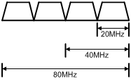
Setting the 802.11ac bandwidth mode in radio view
|
Step |
Command |
Remarks |
|
1. Enter system view. |
system-view |
N/A |
|
2. Create an AP and enter AP view. |
wlan ap ap-name [ model model-name ] |
By default, no AP is created. You must specify the name and model when you create an AP. |
|
3. Enter radio view. |
radio radio-id |
N/A |
|
4. Set the 802.11ac bandwidth mode. |
· Set the 802.11ac bandwidth mode: · Set the 802.11gac bandwidth mode: |
By default, the radio uses the configuration in AP group view. |
Setting the 802.11ac bandwidth mode in AP group radio view
|
Step |
Command |
Remarks |
|
1. Enter system view. |
system-view |
N/A |
|
2. Create an AP group and enter AP group view. |
wlan ap-group group-name |
By default, the default AP group default-group exists and it cannot be deleted. |
|
3. Enter AP model view. |
ap-model ap-model |
N/A |
|
4. Enter radio view. |
radio radio-id |
N/A |
|
5. Set the 802.11ac bandwidth mode. |
· Set the 802.11ac
bandwidth mode: · Set the 802.11gac
bandwidth mode: |
By default, the bandwidth mode is 80 MHz and 20 MHz for 802.11ac and 802.11gac radios, respectively. |
Configuring TxBF
|
|
NOTE: Support for this feature depends on the AP model. |
Transmit beamforming (TxBF) enables an AP to adjust transmitting parameters based on the channel information to focus RF signals on intended clients. This feature improves the RF signal quality. TxBF includes single-user TxBF and multi-user TxBF.
· Single-user TxBF—Single-user TxBF enables an AP to improve the signal to one intended client. Single-user TxBF is applicable to WLANs that have widely spread clients, poor network quality, and serious signal attenuation.
· Multi-user TxBF—Multi-user TxBF is part of 802.11ac Wave2. Multi-user TxBF enables an AP to focus different RF signals on their intended clients to reduce interference and transmission delay. This improves traffic throughput and bandwidth usage. Multi-user TxBF is applicable to WLANs that have a large number of clients and require high bandwidth usage and low transmission delay.
Configuring TxBF in radio view
|
Step |
Command |
Remarks |
|
1. Enter system view. |
system-view |
N/A |
|
2. Create an AP and enter AP view. |
wlan ap ap-name [ model model-name ] |
By default, no APs exist. You must specify the name and model when you create an AP. |
|
3. Enter radio view. |
radio radio-id |
N/A |
|
4. Configure single-user TxBF. |
su-txbf { disable | enable } |
By default, a radio uses the configuration in AP group radio view. |
|
5. Configure multi-user TxBF. |
mu-txbf { disable | enable } |
By default, a radio uses the configuration in AP group radio view. Multi-user TxBF takes effect only when single-user TxBF is enabled. |
Configuring TxBF in AP group radio view
|
Step |
Command |
Remarks |
|
1. Enter system view. |
system-view |
N/A |
|
2. Create an AP group and enter AP group view. |
wlan ap-group group-name |
By default, a system-defined AP group exists. This AP group is named default-group and cannot be deleted. |
|
3. Enter AP model view. |
ap-model ap-model |
N/A |
|
4. Enter radio view. |
radio radio-id |
N/A |
|
5. Configure single-user TxBF. |
su-txbf { disable | enable } |
By default, single-user TxBF is enabled. |
|
6. Configure multi-user TxBF. |
mu-txbf { disable | enable } |
By default, multi-user TxBF is enabled. Multi-user TxBF takes effect only when single-user TxBF is enabled. |
Configuring the smart antenna feature
|
|
NOTE: Support for this feature depends on the device model. |
|
|
IMPORTANT: This feature is applicable to only 802.11n and 802.11ac radios. |
The smart antenna feature enables an AP to automatically adjust the antenna parameters based on the client location and channel information to improve signal quality and stability.
You can configure a radio to operate in one of the following smart antenna modes:
· Auto—Uses the high availability mode for audio and video packets, and uses the high throughput mode for other packets.
· High-availability—Applicable to WLANs that require stable bandwidth, this mode reduces noise and interference impacts and ensures the bandwidth for clients.
· High-throughput—Applicable to WLANs that require high performance, this mode enhances signal strength and association capability.
Configuring the smart antenna feature in radio view
|
Step |
Command |
Remarks |
|
1. Enter system view. |
system-view |
N/A |
|
2. Create an AP and enter AP view. |
wlan ap ap-name [ model model-name ] |
By default, no AP is created. You must specify the name and model when you create an AP. |
|
3. Enter radio view. |
radio radio-id |
N/A |
|
4. Enable the smart antenna feature. |
smart antenna enable |
By default, the radio uses the configuration in AP group view. |
|
5. Specify a smart antenna mode. |
smart-antenna policy { auto | high-availability | high-throughput } |
By default, the radio uses the configuration in AP group view. |
Configuring the smart antenna feature in AP group radio view
|
Step |
Command |
Remarks |
|
1. Enter system view. |
system-view |
N/A |
|
2. Create an AP group and enter AP group view. |
wlan ap-group group-name |
By default, the default AP group default-group exists and cannot be deleted. |
|
3. Enter AP model view. |
ap-model ap-model |
N/A |
|
4. Enter radio view. |
radio radio-id |
N/A |
|
5. Enable the smart antenna feature. |
smart antenna enable |
By default, the smart antenna feature is enabled. |
|
6. Specify a smart antenna mode. |
smart-antenna policy { auto | high-availability | high-throughput } |
By default, the auto mode is used. |
Displaying and maintaining radio management
Execute display commands in any view and reset commands in user view.
|
Task |
Command |
|
Display AP radio information. |
display wlan ap { all | name ap-name } radio [ frequency-band { 5 | 2.4 } ] |
|
Display radio channel information. |
display wlan ap { all | name ap-name } radio channel |
|
Display radio type information. |
display wlan ap { all | name ap-name } radio type |
|
Display radio statistics. |
display wlan ap { all | name ap-name } radio-statistics |
|
Clear radio statistics. |
reset wlan ap { all | name ap-name } radio-statistics |
Radio management configuration examples
Basic radio function configuration example
Network requirements
As shown in Figure 11, create a manual AP and set the radio mode, working channel, and maximum transmit power to 802.11gn, channel 11, and 19 dBm, respectively.
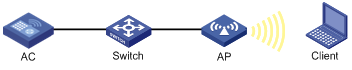
Configuration procedure
# Create the manual AP ap1, and specify its model and serial ID.
<AC> system-view
[AC] wlan ap ap1 model WA536-WW
[AC-wlan-ap-ap1] serial-id 219801A1NQB117012935
# Enter radio view of radio 2.
[AC-wlan-ap-ap1] radio 2
# Set the radio mode to dot11gn.
[AC-wlan-ap-ap1-radio-2] type dot11gn
# Configure radio 2 to work on channel 11.
[AC-wlan-ap-ap1-radio-2] channel 11
# Set the maximum transmit power to 19 dBm.
[AC-wlan-ap-ap1-radio-2] max-power 19
# Enable radio 2.
[AC-wlan-ap-ap1-radio-2] radio enable
[AC-wlan-ap-ap1-radio-2] return
Verifying the configuration
# View information about all radios.
<AC> display wlan ap all verbose
Total number of APs: 1
Total number of connected APs: 1
Total number of connected manual APs: 1
Total number of connected auto APs: 0
Total number of connected common APs: 1
Total number of connected WTUs: 0
Total number of inside APs: 0
Maximum supported APs: 3072
Remaining APs: 3071
AP name : ap1
AP ID : 1
AP group name : default-group
State : Run
Backup type : Master
Online time : 0 days 1 hours 25 minutes 12 seconds
System up time : 0 days 2 hours 22 minutes 12 seconds
Model : WA536-WW
Region code : CN
Region code lock : Disable
Serial ID : 219801A1NQB117012935
MAC address : 0AFB-423B-893C
IP address : 192.168.1.50
UDP port number : 65488
H/W version : Ver.C
S/W version : R2206P02
Boot version : 1.01
Description : wtp1
Priority : 4
Echo interval : 10 seconds
Statistics report interval : 50 seconds
Fragment size (data) : 1500
Fragment size (control) : 1450
MAC type : Local MAC & Split MAC
Tunnel mode : Local Bridging & 802.3 Frame & Native Frame
Discovery type : Static Configuration
Retransmission count : 3
Retransmission interval : 5 seconds
Firmware upgrade : Enabled
Sent control packets : 1
Received control packets : 1
Echo requests : 147
Lost echo responses : 0
Average echo delay : 3
Last reboot reason : User soft reboot
Latest IP address : 10.1.0.2
Tunnel down reason : Request wait timer expired
Connection count : 1
Backup Ipv4 : Not configured
Backup Ipv6 : Not configured
Tunnel encryption : Disabled
LED mode : Normal
Remote configuration : Enabled
Radio 1:
Basic BSSID : 7848-59f6-3940
Admin state : Up
Radio mode : 802.11ac
Antenna type : internal
Client dot11ac-only : Disabled
Client dot11n-only : Disabled
Channel band-width : 20/40/80MHz
Secondary channel offset : SCB
Short GI for 20MHz : Supported
Short GI for 40MHz : Supported
Short GI for 80MHz : Supported
Short GI for 160MHz : Not supported
A-MSDU : Enabled
A-MPDU : Enabled
LDPC : Not Supported
STBC : Supported
Operational VHT-MCS Set:
Mandatory : Not configured
Supported : NSS1 0,1,2,3,4,5,6,7,8,9
NSS2 0,1,2,3,4,5,6,7,8,9
Multicast : Not configured
Operational HT MCS Set:
Mandatory : Not configured
Supported : 0, 1, 2, 3, 4, 5, 6, 7, 8, 9,
10, 11, 12, 13, 14, 15
Multicast : Not configured
Channel : 44(auto)
Max power : 20 dBm
Operational rate:
Mandatory : 6, 12, 24 Mbps
Multicast : Auto
Supported : 9, 18, 36, 48, 54 Mbps
Disabled : Not configured
Distance : 1 km
ANI : Enabled
Fragmentation threshold : 2346 bytes
Beacon interval : 100 TU
Protection threshold : 2346 bytes
Long retry threshold : 4
Short retry threshold : 7
Maximum rx duration : 2000 ms
Noise Floor : –102 dBm
Smart antenna : Enabled
Smart antenna policy : Auto
Protection mode : rts-cts
Continuous mode : N/A
HT protection mode : No protection
Radio 2:
Basic BSSID : 7848-59f6-3950
Admin state : Up
Radio mode : 802.11n(2.4GHz)
Antenna type : internal
Client dot11n-only : Disabled
Channel band-width : 20MHz
Secondary channel offset : SCN
Short GI for 20MHz : Supported
Short GI for 40MHz : Supported
A-MSDU : Enabled
A-MPDU : Enabled
LDPC : Not Supported
STBC : Supported
Operational HT MCS Set:
Mandatory : Not configured
Supported : 0, 1, 2, 3, 4, 5, 6, 7, 8, 9,
10, 11, 12, 13, 14, 15
Multicast : Not configured
Channel : 11
Max power : 19 dBm
Preamble type : Short
Operational rate:
Mandatory : 1, 2, 5.5, 11 Mbps
Multicast : Auto
Supported : 6, 9, 12, 18, 24, 36, 48, 54 Mbps
Disabled : Not configured
Distance : 1 km
ANI : Enabled
Fragmentation threshold : 2346 bytes
Beacon interval : 100 TU
Protection threshold : 2346 bytes
Long retry threshold : 4
Short retry threshold : 7
Maximum rx duration : 2000 ms
Noise Floor : –105 dBm
Smart antenna : Enabled
Smart antenna policy : Auto
Protection mode : rts-cts
Continuous mode : N/A
HT protection mode : No protection
802.11n configuration example
Network requirements
As shown in Figure 12, specify radio 1 on the AP as an 802.11an radio, and enable the A-MSDU and A-MPDU aggregation methods on the radio.
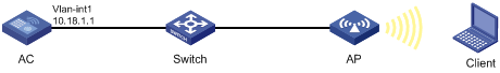
Configuration procedure
# Create the manual AP ap1, and specify its model and serial ID.
<AC> system-view
[AC] wlan ap ap1 model WA536-WW
[AC-wlan-ap-ap1] serial-id 219801A1NQB117012935
# Enter radio view of radio 1 on AP 1, and specify the radio as an 802.11an radio.
[AC-wlan-ap-ap1] radio 1
[AC-wlan-ap-ap1-radio-1] type dot11an
# Enable the A-MPDU and A-MSDU aggregation methods.
[AC-wlan-ap-ap1-radio-1] a-mpdu enable
[AC-wlan-ap-ap1-radio-1] a-msdu enable
# Enable radio 1.
[AC-wlan-ap-ap1-radio-1] radio enable
[AC-wlan-ap-ap1-radio-1] return
Verifying the configuration
# View information about radios on AP 1.
<AC> display wlan ap name ap1 verbose
AP name : ap1
AP ID : 1
AP group name : default-group
State : Run
Backup type : Master
Online time : 0 days 1 hours 25 minutes 12 seconds
System up time : 0 days 2 hours 22 minutes 12 seconds
Model : WA536-WW
Region code : CN
Region code lock : Disable
Serial ID : 219801A1NQB117012935
MAC address : 0AFB-423B-893C
IP address : 192.168.1.50
UDP port number : 65488
H/W version : Ver.C
S/W version : R2206P02
Boot version : 1.01
Description : wtp1
Priority : 4
Echo interval : 10 seconds
Statistics report interval : 50 seconds
Fragment size (data) : 1500
Fragment size (control) : 1450
MAC type : Local MAC & Split MAC
Tunnel mode : Local Bridging & 802.3 Frame & Native Frame
Discovery type : Static Configuration
Retransmission count : 3
Retransmission interval : 5 seconds
Firmware upgrade : Enabled
Sent control packets : 1
Received control packets : 1
Echo requests : 147
Lost echo responses : 0
Average echo delay : 3
Last reboot reason : User soft reboot
Latest IP address : 10.1.0.2
Tunnel down reason : Request wait timer expired
Connection count : 1
Backup Ipv4 : Not configured
Backup Ipv6 : Not configured
Tunnel encryption : Disabled
LED mode : Normal
Remote configuration : Enabled
Radio 1:
Basic BSSID : 7848-59f6-3940
Admin state : Up
Radio mode : 802.11n(5GHz)
Antenna type : internal
Client dot11ac-only : Disabled
Client dot11n-only : Disabled
Channel band-width : 20/40/80MHz
Secondary channel offset : SCB
Short GI for 20MHz : Supported
Short GI for 40MHz : Supported
Short GI for 80MHz : Supported
Short GI for 160MHz : Not supported
A-MSDU : Enabled
A-MPDU : Enabled
LDPC : Not Supported
STBC : Supported
Operational VHT-MCS Set:
Mandatory : Not configured
Supported : NSS1 0,1,2,3,4,5,6,7,8,9
NSS2 0,1,2,3,4,5,6,7,8,9
Multicast : Not configured
Operational HT MCS Set:
Mandatory : Not configured
Supported : 0, 1, 2, 3, 4, 5, 6, 7, 8, 9,
10, 11, 12, 13, 14, 15
Multicast : Not configured
Channel : 44(auto)
Max power : 20 dBm
Operational rate:
Mandatory : 6, 12, 24 Mbps
Multicast : Auto
Supported : 9, 18, 36, 48, 54 Mbps
Disabled : Not configured
Distance : 1 km
ANI : Enabled
Fragmentation threshold : 2346 bytes
Beacon interval : 100 TU
Protection threshold : 2346 bytes
Long retry threshold : 4
Short retry threshold : 7
Maximum rx duration : 2000 ms
Noise Floor : –102 dBm
Smart antenna : Enabled
Smart antenna policy : Auto
Protection mode : rts-cts
Continuous mode : N/A
HT protection mode : No protection
Radio 2:
Basic BSSID : 7848-59f6-3950
Admin state : Up
Radio mode : 802.11n(2.4GHz)
Antenna type : internal
Client dot11n-only : Disabled
Channel band-width : 20MHz
Secondary channel offset : SCN
Short GI for 20MHz : Supported
Short GI for 40MHz : Supported
A-MSDU : Enabled
A-MPDU : Enabled
LDPC : Not Supported
STBC : Supported
Operational HT MCS Set:
Mandatory : Not configured
Supported : 0, 1, 2, 3, 4, 5, 6, 7, 8, 9,
10, 11, 12, 13, 14, 15
Multicast : Not configured
Channel : 11
Max power : 19 dBm
Preamble type : Short
Operational rate:
Mandatory : 1, 2, 5.5, 11 Mbps
Multicast : Auto
Supported : 6, 9, 12, 18, 24, 36, 48, 54 Mbps
Disabled : Not configured
Distance : 1 km
ANI : Enabled
Fragmentation threshold : 2346 bytes
Beacon interval : 100 TU
Protection threshold : 2346 bytes
Long retry threshold : 4
Short retry threshold : 7
Maximum rx duration : 2000 ms
Noise Floor : -105 dBm
Smart antenna : Enabled
Smart antenna policy : Auto
Protection mode : rts-cts
Continuous mode : N/A
HT protection mode : No protection
Configuring WLAN access
This chapter describes how to configure WLAN access.
WLAN access overview
A wireless client can access a WLAN only when it completes the scanning, link layer authentication, association, and WLAN authentication processes.
For more information about data link layer authentication, see "Configuring WLAN security."
For more information about WLAN authentication, see "Configuring WLAN authentication."
Figure 13 WLAN access process
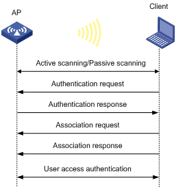
Scanning
Active scanning
A wireless client periodically scans surrounding wireless networks by sending probe requests. It obtains network information from received probe responses. Based on whether a probe request carries an SSID, active scanning can be divided into the following types:
· Active scanning of all wireless networks.
As shown in Figure 14, the client periodically sends a probe request on each of its supported channels to scan wireless networks. APs that receive the probe request send a probe response, which carries the available wireless network information. The client associates with the optimal AP.
Figure 14 Scanning all wireless networks
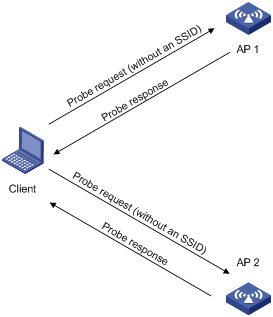
· Active scanning of a specific wireless network.
As shown in Figure 15, the client periodically sends a probe request carrying the specified SSID if the wireless client has an SSID configured or has been associated with an SSID. When an AP that can provide wireless services with the specified SSID receives the probe request, it sends a probe response.
Figure 15 Scanning a specific wireless network
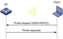
Passive scanning
As shown in Figure 16, the clients periodically listen to beacon frames sent by APs on their supported channels to get information about surrounding wireless networks. Then the clients select an AP for association. Passive scanning is used when clients want to save power.
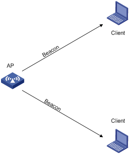
Association
A client sends an association request to the associated AP after passing date link layer authentication. Upon receiving the request, the AP determines the capability supported by the wireless client and sends an association response to the client. Then the client is associated with the AP.
Client access control
The following client access control methods are available:
· AP group-based access control—Allows clients associated with APs in the specified AP group to access the WLAN.
· SSID-based access control—Allows clients associated with the specified SSID to access the WLAN.
· Whitelist- and blacklist-based access control—Uses the whitelist and blacklists to control access for the specified clients.
AP group-based access control
As shown in Figure 17, for AP group-based access control, configure AP group 1 as the permitted AP group for Client 1 and Client 2, and configure AP group 2 as the permitted AP group for Client 3.
When a client passes authentication, the server sends the related user profile to the AC. The AC examines whether the AP with which the client associates is in the permitted AP group. If it is, the client is allowed to access the WLAN. If it is not, the AC logs off the client.
Figure 17 AP group-based access control
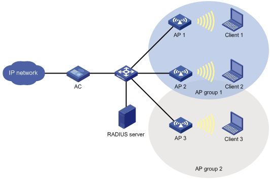
SSID-based access control
As shown in Figure 18, for SSID-based access control, configure ssida as the permitted SSID for Client 1 and Client 2, and configure ssidb as the permitted SSID for Client 3.
When a client passes authentication, the server sends the related user profile to the AC. The AC examines whether the associated SSID of the client is the permitted SSID. If it is, the client is allowed to access the WLAN. If it is not, the AC logs off the client.
Figure 18 AP group-based access control
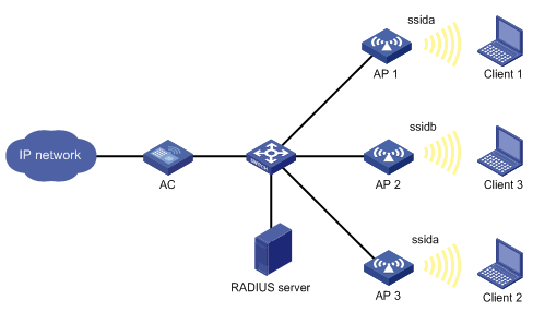
Whitelist- and blacklist-based access control
You can configure the whitelist or blacklists to filter frames from WLAN clients and implement client access control.
· Whitelist—Contains the MAC addresses of all clients allowed to access the WLAN. Frames from clients not in the whitelist are discarded. This list is manually configured.
· Static blacklist—Contains the MAC addresses of clients forbidden to access the WLAN. This list is manually configured.
· Dynamic blacklist—Contains the MAC addresses of clients forbidden to access the WLAN. An AP adds the MAC address of a client forbidden to access the WLAN to the list when WIPS is configured or when URL redirection is enabled for WLAN MAC authentication clients. The entries in the list are removed when the aging timer expires. For more information about WIPS, see "Configuring WIPS". For more information about WLAN MAC authentication, see "Configuring WLAN authentication."
When an AP receives an association request and sends an Add Mobile message to the AC, the AC performs the following operations to determine whether to permit the client:
1. Searches the whitelist.
? If the client MAC address does not match any entries in the whitelist, the client is rejected.
? If a match is found, the client is permitted.
2. Searches the static and dynamic blacklists if no whitelist entries exist.
? If the client MAC address matches an entry in either blacklist, the client is rejected.
? If no match is found, or no blacklist entries exist, the client is permitted.
Figure 19 Whitelist- and blacklist-based access control
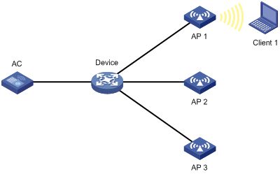
Configuration restrictions and guidelines
The priorities for the configuration in AP view, AP group view, and global configuration view are in descending order.
Configuration task list
Configuring a service template
A service template defines a set of wireless service attributes, such as SSID and authentication method.
To configure a service template:
|
Command |
Remarks |
|
|
1. Enter system view. |
N/A |
|
|
2. Create a service template. |
By default, no service template exists. |
|
|
3. Assign clients coming online through the service template to a VLAN. |
By default, clients are assigned to VLAN 1 after coming online through a service template. |
Setting an SSID
APs advertise SSIDs in beacon frames. If the number of clients in a BSS exceeds the limit or the BSS is unavailable, you can enable SSID-hidden to prevent clients from discovering the BSS. When SSID-hidden is enabled, the BSS hides its SSID in beacon frames and does not respond to broadcast probe requests. A client must send probe requests with the specified SSID to access the WLAN. This feature can protect the WLAN from being attacked.
To set an SSID:
|
Command |
Remarks |
|
|
1. Enter system view. |
N/A |
|
|
2. Enter service template view. |
N/A |
|
|
3. Set an SSID for the service template. |
By default, no SSID is set for a service template. As a best practice, set a unique SSID for a service template. |
|
|
4. (Optional.) Enable SSID-hidden in beacon frames. |
By default, beacon frames carry SSIDs. |
Configuring a description for a service template
|
Step |
Command |
Remarks |
|
1. Enter system view. |
system-view |
N/A |
|
2. Enter service template view. |
wlan service-template service-template-name |
N/A |
|
3. Configure a description for the service template. |
description text |
By default, a service template does not have a description. |
Specifying the VLAN allocation method for clients
When a client comes online for the first time, the radio assigns a random VLAN to it. When the client comes online again, the VLAN assigned to the client depends on the allocation method.
· Static allocation—The client inherits the VLAN that has been assigned to it. If the IP address lease has not expired, the client will use the same IP address. This method helps save IP addresses.
· Dynamic allocation—The client is re-assigned a VLAN. This method balances clients in all VLANs.
Removing VLANs from or adding VLANs to a client VLAN group does not affect online clients.
After a client goes offline and comes online again, its VLAN might change in the following situations:
· In static allocation mode, the AP will assign a new VLAN to the client if its original VLAN has been removed from the VLAN group.
· If you change the VLAN allocation method from dynamic to static, the AP might assign the clients a different VLAN after they come online again.
To specify the VLAN allocation method for clients:
|
Step |
Command |
Remarks |
|
1. Enter system view. |
system-view |
N/A |
|
2. Enter service template view. |
wlan service-template service-template-name |
N/A |
|
3. Specify the VLAN allocation method for clients. |
client vlan-alloc { dynamic | static } |
By default, the VLAN allocation method for clients is dynamic. |
Configuring clients to prefer the authorization VLAN after roaming
As a best practice, configure this feature on all ACs in a mobility group.
Typically, the VLAN of a client remains unchanged after client roaming. However, if the client triggers a security alert configured on IMC after roams to another AP, the issued authorization VLAN for user isolation takes effect.
This feature takes effect only on 802.1X and MAC authentication clients.
To configure clients to prefer the authorization VLAN after roaming:
|
Step |
Command |
Remarks |
|
1. Enter system view. |
system-view |
N/A |
|
2. Enter service template view. |
wlan service-template service-template-name |
N/A |
|
3. Configure clients to prefer the authorization VLAN after roaming. |
client preferred-vlan authorized |
By default, clients prefer the authorization VLAN after roaming. |
Setting the client cache aging time
The client cache saves information such as the PMK list and access VLAN for clients. If a client roams to another AP before the cache aging time expires, the client can inherit the cache information. If a client does not come online before the cache aging time expires, its cache information is cleared.
To set the client cache aging time:
|
Step |
Command |
Remarks |
|
1. Enter system view. |
system-view |
N/A |
|
2. Enter service template view. |
wlan service-template service-template-name |
N/A |
|
3. Set the client cache aging time. |
client cache aging-time aging-time |
By default, the client cache aging time is 180 seconds. |
Enabling client association at the AC or APs
If you enable client association at the AC, management frames are sent to the AC over the CAPWAP tunnel. This ensures security and facilitates management. As a best practice, enable client association at the APs when the network between AC and AP is complicated.
Layer 3 roaming is not supported if client association is enabled at APs. When you use the service-template command, you must specify the same VLAN for the APs that use the same service template and have overlapping coverage areas.
To enable client association at the AC or APs:
|
Step |
Command |
Remarks |
|
1. Enter system view. |
system-view |
N/A |
|
2. Enter service template view. |
wlan service-template service-template-name |
N/A |
|
3. Enable client association at the AC or APs. |
client association-location { ac | ap } |
By default, client association is performed at the AC. |
Specifying the client traffic forwarder
The client traffic forwarder can be the AC (centralized forwarding) or APs (local forwarding). Using APs to forward client traffic releases the forwarding burden on the AC.
If APs forward client traffic, you can specify a VLAN or a VLAN range for the APs to forward traffic from the specified VLANs. The AC forwards data traffic from the other VLANs.
For the configuration of using the AC to forward client traffic to take effect, make sure client traffic forwarding has been enabled.
To specify the client traffic forwarder:
|
Step |
Command |
Remarks |
|
1. Enter system view. |
system-view |
N/A |
|
2. Enter service template view. |
wlan service-template service-template-name |
N/A |
|
3. Specify the client traffic forwarder. |
client forwarding-location { ac | ap [ vlan { vlan-start [ to vlan-end ] } ] } |
The AC forwards client data traffic. |
Enabling client traffic forwarding
You must enable this feature if you configure the AC as the client traffic forwarder.
To enable client traffic forwarding:
|
Step |
Command |
Remarks |
|
1. Enter system view. |
system-view |
N/A |
|
2. Enable client traffic forwarding. |
wlan client forwarding enable |
By default, client traffic forwarding is enabled. |
Setting the encapsulation format for client data frames
In the centralized forwarding infrastructure, an AP sends data frames from clients to the AC over the CAPWAP tunnel. You can set the encapsulation format for the client data frames to 802.3 or 802.11. As a best practice, set the format to 802.3 so the AC does not need to perform frame format conversion.
To set the encapsulation format for client data frames:
|
Step |
Command |
Remarks |
|
1. Enter system view. |
system-view |
N/A |
|
2. Enter service template view. |
wlan service-template service-template-name |
N/A |
|
3. Set the encapsulation format for client data frames. |
client frame-format { dot3 | dot11 } |
By default, client data frames are encapsulated in the 802.3 format. |
Enabling quick association
Enabling load balancing or band navigation might affect client association efficiency. For delay-sensitive services or in an environment where load balancing and band navigation is not needed, you can enable quick association for a service template.
This feature disables the device from performing load balancing or band navigation on clients associated with the service template even if load balancing and band navigation is enabled in the WLAN.
To enable quick association:
|
Step |
Command |
Remarks |
|
1. Enter system view. |
system-view |
N/A |
|
2. Enter service template view. |
wlan service-template service-template-name |
N/A |
|
3. Enable quick association. |
By default, quick association is disabled. |
Enabling a service template
|
Command |
Remarks |
|
|
1. Enter system view. |
N/A |
|
|
2. Enter service template view. |
N/A |
|
|
3. Enable the service template. |
By default, a service template is disabled. |
Binding a service template to a radio
If you bind a service template to a radio, the AP creates a BSS that can provide wireless services defined in the service template.
You can perform the following tasks when binding a service template to a radio:
· Bind a VLAN group to the radio so that clients associated with the BSS will be assigned evenly to all VLANs in the VLAN group.
· Bind the NAS port ID or the NAS ID to the radio to identify the network access server.
· Enable the AP to hide SSIDs in beacon frames.
Binding a service template to a radio in radio view
|
Command |
Remarks |
|
|
1. Enter system view. |
N/A |
|
|
2. Enter AP view. |
N/A |
|
|
3. Enter radio view. |
N/A |
|
|
4. Bind a service template to the radio. |
service-template service-template-name [ vlan vlan-id | vlan-group vlan-group-name ] [ ssid-hide ] [ nas-id nas-id | nas-port-id nas-port-id ] |
By default, the configuration in AP group view is used. You can bind a maximum of 16 service templates to a radio. |
Binding a service template to a radio in AP group radio view
|
Step |
Command |
Remarks |
|
1. Enter system view. |
system-view |
N/A |
|
2. Enter AP group view. |
wlan ap-group group-name |
N/A |
|
3. Enter AP model view. |
ap-model ap-model |
N/A |
|
4. Enter radio view. |
radio radio-id |
N/A |
|
5. Bind a service template to the radio. |
service-template service-template-name [ vlan vlan-id | vlan-group vlan-group-name ] [ ssid-hide ] [ nas-id nas-id | nas-port-id nas-port-id ] |
By default, a radio is not bound to any service templates. You can bind a maximum of 16 service templates to a radio. |
Specifying a region code
A region code determines characteristics such as available frequencies, available channels, and transmit power level. Set a valid region code before configuring an AP.
To prevent regulation violation caused by region code modification, lock the region code.
Specifying a region code in AP view
|
Step |
Command |
Remarks |
|
1. Enter system view. |
system-view |
N/A |
|
2. Enter AP view. |
N/A |
|
|
3. Specify a region code. |
By default, the AP uses the configuration in AP group view. If no region code exists in AP group view, the AP uses the configuration in global configuration view. |
|
|
4. Lock the region code. |
By default, the AP uses the configuration in AP group view. If no configuration exists in AP group view, the AP uses the configuration in global configuration view. |
Specifying a region code in AP group view
|
Step |
Command |
Remarks |
|
1. Enter system view. |
system-view |
N/A |
|
2. Enter AP group view. |
N/A |
|
|
3. Specify a region code. |
region-code code |
By default, the AP group uses the configuration in global configuration view. |
|
4. Lock the region code. |
region-code-lock enable |
By default, the AP group uses the configuration in global configuration view. |
Specifying a global region code
|
Step |
Command |
Remarks |
|
1. Enter system view. |
system-view |
N/A |
|
2. Enter global configuration view. |
N/A |
|
|
3. Specify a region code. |
region-code code |
By default, no region code is specified. |
|
4. Lock the region code. |
region-code-lock enable |
By default, the region code is not locked. |
Disabling an AP from responding to broadcast probe requests
Broadcast probe requests do not carry any SSIDs. Upon receiving a broadcast probe request, an AP responds with a probe response that carries service information for the AP.
This feature enables clients that send unicast probe requests to the AP to associate with the AP more easily.
Disabling an AP from responding to broadcast probe requests in AP view
|
Step |
Command |
Remarks |
|
1. Enter system view. |
system-view |
N/A |
|
2. Enter AP view. |
N/A |
|
|
3. Disable the AP from responding to broadcast probe requests. |
broadcast-probe reply disable |
By default, the AP uses the configuration in AP group view. |
Disabling APs in an AP group from responding to broadcast probe requests in AP group view
|
Step |
Command |
Remarks |
|
1. Enter system view. |
system-view |
N/A |
|
2. Enter AP group view. |
N/A |
|
|
3. Disable APs in the AP group from responding to broadcast probe requests. |
By default, an AP responds to broadcast probe requests. |
Setting the client idle timeout timer
If an online client does not send any frames to the associated AP before the client idle timeout timer expires, the AP logs off the client.
Setting the client idle timeout timer in AP view
|
Step |
Command |
Remarks |
|
1. Enter system view. |
system-view |
N/A |
|
2. Enter AP view. |
wlan ap ap-name [ model model-name ] |
N/A |
|
3. Set the client idle timeout timer. |
By default, the AP uses the configuration in AP group view. |
Setting the client idle timeout timer in AP group view
|
Step |
Command |
Remarks |
|
1. Enter system view. |
system-view |
N/A |
|
2. Enter AP group view. |
N/A |
|
|
3. Set the client idle timeout timer. |
client idle-timeout interval |
By default, the client idle timeout timer is 3600 seconds. |
Configuring client keepalive
This feature enables an AP to send keepalive packets to clients at the specified interval to identify whether the clients are online. If the AP does not receive any replies from a client within three keepalive intervals, it logs off the client.
Configuring client keepalive in AP view
|
Step |
Command |
Remarks |
|
1. Enter system view. |
system-view |
N/A |
|
2. Enter AP view. |
wlan ap ap-name [ model model-name ] |
N/A |
|
3. Enable client keepalive. |
By default, the AP uses the configuration in AP group view. |
|
|
4. (Optional.) Set the client keepalive interval. |
By default, the AP uses the configuration in AP group view. |
Configuring client keepalive in AP group view
|
Step |
Command |
Remarks |
|
1. Enter system view. |
system-view |
N/A |
|
2. Enter AP group view. |
N/A |
|
|
3. Enable client keepalive. |
client keep-alive enable |
By default, client keepalive is disabled. |
|
4. (Optional.) Set the client keepalive interval. |
client keep-alive interval value |
By default, the client keepalive interval is 300 seconds. |
Configuring an AP to not inherit the specified service template from an AP group
By default, APs in an AP group inherit the service template bound to the AP group and create BSSs. You can perform this task to configure an AP to not inherit the specified service template from an AP group.
To configure an AP to not inherit the specified service template from an AP group:
|
Step |
Command |
Remarks |
|
1. Enter system view. |
system-view |
N/A |
|
2. Enter AP view. |
N/A |
|
|
3. Enter radio view. |
N/A |
|
|
4. Configure the AP to not inherit the specified service template from an AP group. |
By default, an AP inherits the service template bound to an AP group. |
Setting the NAS ID
A network access server identifier (NAS ID), network access server port identifier (NAS port ID), or network access server VLAN identifier (NAS VLAN ID) identifies the network access server of a client and differentiates the source of client traffic.
If you specify a NAS ID or NAS port ID when binding a service template to a radio, the radio uses the NAS ID or NAS port ID specified for the service template.
If a NAS port ID has been specified by using the nas-port-id command, clients use the specified NAS port ID. If no NAS port ID is specified, clients use the specified NAS port ID format to generate NAS port IDs.
Setting the NAS ID in AP view
|
Step |
Command |
Remarks |
|
1. Enter system view. |
system-view |
N/A |
|
2. Set the format of NAS port IDs for wireless clients. |
wlan nas-port-id format { 2 | 4 } |
By default, clients use format 2 to generate NAS port IDs. |
|
3. Enter AP view. |
wlan ap ap-name [ model model-name ] |
N/A |
|
4. Set the NAS ID. |
nas-id nas-id |
By default, the AP uses the configuration in AP group view. If no NAS ID is specified in AP group view, the AP uses the configuration in global configuration view. |
|
5. Set the NAS port ID. |
nas-port-id nas-port-id |
By default, an AP uses the configuration in AP group view. If no NAS port ID is specified in AP group view, the AP uses the configuration in global configuration view. |
|
6. Set the NAS VLAN ID and enable the AC to encapsulate the VLAN ID in RADIUS requests. |
nas-vlan vlan-id |
By default, no NAS VLAN ID is set. Authentication requests sent to the RADIUS server do not contain the NAS VLAN ID field. Set the NAS VLAN ID when a third-party Security Accounting Management (SAM) server is used as the RADIUS server. |
Setting the NAS ID in AP group view
|
Step |
Command |
Remarks |
|
1. Enter system view. |
system-view |
N/A |
|
2. Set the format of NAS port IDs for wireless clients. |
wlan nas-port-id format { 2 | 4 } |
By default, clients use format 2 to generate NAS port IDs. |
|
3. Enter AP group view. |
wlan ap-group group-name |
N/A |
|
4. Set the NAS ID. |
nas-id nas-id |
By default, the AP uses the configuration in global configuration view. |
|
5. Set the NAS port ID. |
nas-port-id nas-port-id |
By default, an AP uses the configuration in global configuration view. |
Setting the global NAS ID
|
Step |
Command |
Remarks |
|
1. Enter system view. |
system-view |
N/A |
|
2. Set the format of NAS port IDs for wireless clients. |
wlan nas-port-id format { 2 | 4 } |
By default, clients use format 2 to generate NAS port IDs. |
|
3. Enter global configuration view. |
wlan global-configuration |
N/A |
|
4. Set the global NAS ID. |
nas-id nas-id |
By default, no NAS ID is set. |
|
5. Set the NAS port ID. |
nas-port-id nas-port-id |
By default, no NAS port ID is set. |
Setting the way in which an AP processes traffic from unknown clients
|
Step |
Command |
Remarks |
|
1. Enter system view. |
system-view |
N/A |
|
2. Enter service template view. |
N/A |
|
|
3. Set the way in which an AP processes traffic from unknown clients. |
By default, an AP drops packets from unknown clients and deauthenticates these clients. |
Configuring policy-based forwarding
Forwarding policies enable the AC to perform policy-based forwarding for different client traffic flows.
You can apply a forwarding policy to a service template or user profile. The AC preferentially uses the forwarding policy applied to a user profile to direct client traffic forwarding. If the user profile of a client does not have a forwarding policy, the AC uses the forwarding policy applied to the service template.
For forwarding policies to take effect, you must specify the AC to perform authentication for clients. For more information about specifying the authentication location, see "Configuring WLAN authentication."
Make sure the AC and its associated APs are in different network segments.
Configuring a forwarding policy
A forwarding policy contains one or multiple forwarding rules. Each forwarding rule specifies a traffic match criterion and the forwarding mode for matching traffic. The traffic match criterion can be a basic ACL, an advanced ACL, or a Layer 2 ACL. The forwarding mode can be local forwarding or centralized forwarding.
Actions defined in ACL rules do not take effect in wireless packet forwarding. All matched packets are forwarded based on the forwarding mode.
For more information about ACLs, see ACL and QoS Configuration Guide.
To configure a forwarding policy:
|
Step |
Command |
Remarks |
|
1. Enter system view. |
system-view |
N/A |
|
2. Create a forwarding policy and enter its view. |
wlan forwarding-policy policy-name |
By default, no forwarding policies are configured. |
|
3. Configure a forwarding rule. |
classifier acl { acl-number | ipv6 ipv6-acl-number } behavior { local | remote } |
By default, no forwarding rules are configured. Repeat this command to configure more forwarding rules. |
Applying a forwarding policy to a service template
|
Step |
Command |
Remarks |
|
1. Enter system view. |
system-view |
N/A |
|
2. Enter service template view. |
wlan service-template service-template-name |
N/A |
|
3. Apply a forwarding policy to the service template. |
client forwarding-policy-name policy-name |
By default, no forwarding policy is applied to a service template. |
|
4. Enable policy-based forwarding. |
client forwarding-policy enable |
By default, policy-based forwarding is disabled for a service template. For the forwarding policy to take effect, you must enable policy-based forwarding for the service template. |
Applying a forwarding policy to a user profile
For the AC to perform policy-based forwarding for clients that use a user profile, apply a forwarding policy to the user profile. After a client passes authentication, the authentication server sends the user profile name specified for the client to the AC. The AC will forward traffic of the client based on the forwarding policy applied to the user profile.
If you modify or delete the applied forwarding policy, the change takes effect when the client comes online again.
To apply a forwarding policy to a user profile:
|
Step |
Command |
Remarks |
|
1. Enter system view. |
system-view |
N/A |
|
2. Enter user profile view. |
user-profile profile-name |
N/A |
|
3. Apply a forwarding policy to the user profile. |
wlan client forwarding-policy-name policy-name |
By default, no forwarding policy is applied to a user profile. |
|
4. Return to system view. |
quit |
N/A |
|
5. Enter service template view. |
wlan service-template service-template-name |
N/A |
|
6. Enable policy-based forwarding. |
client forwarding-policy enable |
By default, policy-based forwarding is disabled for a service template. For the forwarding policy applied to the user profile to take effect, you must enable policy-based forwarding for the service template that the user profile uses. |
Specifying a permitted AP group for client access
Perform this task to configure clients to access APs in the specified AP group.
To specify a permitted AP group for client access:
|
Step |
Command |
Remarks |
|
1. Enter system view. |
system-view |
N/A |
|
2. Enter user profile view. |
N/A |
|
|
3. Specify a permitted AP group for client access. |
By default, no permitted AP group is specified for client access. |
Specifying a permitted SSID for client access
Perform this task to configure clients to access a WLAN through the specified SSID.
To specify a permitted SSID for client access:
|
Step |
Command |
Remarks |
|
1. Enter system view. |
system-view |
N/A |
|
2. Enter user profile view. |
user-profile profile-name |
N/A |
|
3. Specify a permitted SSID for client access. |
wlan permit-ssid ssid-name |
By default, no permitted SSID is specified for client access. |
Adding a client to the whitelist
When you add the first client to the whitelist, the system asks you whether to disconnect all online clients. Enter Y at the prompt to configure the whitelist.
To add a client to the whitelist:
|
Step |
Command |
Remarks |
|
1. Enter system view. |
system-view |
N/A |
|
2. Add a client to the whitelist. |
By default, no clients exist in the whitelist. |
Adding a client to the static blacklist
You cannot add a client to both the whitelist and the static blacklist.
To add a client to the static blacklist:
|
Step |
Command |
Remarks |
|
1. Enter system view. |
system-view |
N/A |
|
2. Add a client to the static blacklist. |
By default, no clients exist in the static blacklist. |
Configuring the dynamic blacklist
You can configure the dynamic blacklist to take effect on the AC or on APs.
If you configure the dynamic blacklist to take effect on the AC, all APs connected to the AC will reject the client in the dynamic blacklist. If you configure the dynamic blacklist to take effect on APs, the AP associated with the client in the dynamic blacklist will reject the client, but the client can still associate with other APs connected to the AC. As a best practice, configure the dynamic blacklist to take effect on the AC in high-density environments.
The configured aging time takes effect only on entries added to the dynamic blacklist afterwards.
If the whitelist and blacklists are configured, only the whitelist takes effect.
To configure the dynamic blacklist:
|
Step |
Command |
Remarks |
|
1. Enter system view. |
system-view |
N/A |
|
2. Configure the dynamic blacklist to take effect on the AC or on APs. |
· Configure the dynamic blacklist to take
effect on APs: · Configure the dynamic blacklist to take
effect on the AC: |
By default, the dynamic blacklist takes effect on APs. |
|
3. Set the aging time for dynamic blacklist entries. |
By default, the aging time is 300 seconds. The aging time for dynamic blacklist entries takes effect only on rogue client entries. |
Setting the idle period before client reauthentication
Set the idle period before client reauthentication to reduce reauthentication failures.
When URL redirection is enabled for WLAN MAC authentication clients, an AP logs off a client that has passed MAC authentication. At the next MAC authentication attempt, the client can pass MAC authentication and access the WLAN. With the idle period configured, the AP adds the client to the dynamic blacklist after logging off the client and the client entry ages out after the specified idle period.
To set the idle period before client reauthentication:
|
Step |
Command |
Remarks |
|
1. Enter system view. |
system-view |
N/A |
|
2. Set the idle period before client reauthentication. |
wlan client reauthentication-period [ period-value ] |
By default, the idle period is not configured. |
Deploying a configuration file to an AP
Deploy a configuration file to an AP if you want to update its configuration file or configure features that require a configuration file. For example, to configure a user profile for an AP in local forwarding mode, you must write related commands to a configuration file and then deploy the configuration file to the AP. The configuration file takes effect when the CAPWAP tunnel to the AC is in Run state. It does not survive an AP reboot.
Make sure the configuration file is stored in the storage medium of the AC. Contents in the configuration file must be complete commands.
An AP can only use its main IP address to establish a CAPWAP tunnel to the AC if the AP is configured by using a configuration file.
In an IRF fabric, save the configuration file on each member AC in case of master and backup AC switchover. The map-configuration command takes effect only on the master AC. If you specify a path when executing the command, make sure the path leads to the file on the master AC.
Deploying a configuration file to an AP in AP view
|
Step |
Command |
Remarks |
|
1. Enter system view. |
system-view |
N/A |
|
2. Enter AP view. |
wlan ap ap-name [ model model-name ] |
N/A |
|
3. Deploy a configuration file to the AP. |
map-configuration filename |
By default, no configuration file is deployed to an AP. |
Deploying a configuration file to an AP in AP group AP model view
|
Step |
Command |
Remarks |
|
1. Enter system view. |
system-view |
N/A |
|
2. Enter AP group view. |
wlan ap-group group-name |
N/A |
|
3. Enter AP model view. |
ap-model ap-model |
N/A |
|
4. Deploy a configuration file to the AP. |
map-configuration filename |
By default, no configuration file is deployed to an AP. |
Configuring uplink client rate limit
The following matrix shows the feature and hardware compatibility:
|
Hardware series |
Model |
Uplink client rate limit compatibility |
|
WX1800H series |
WX1804H |
No |
|
WX1810H WX1820H WX1840H |
Yes |
|
|
WX3800H series |
WX3820H WX3840H |
No |
|
WX5800H series |
WX5860H |
No |
Perform this task to limit both the global rate and per-client rate for uplink client packets to ensure both uplink bandwidth usage and per-client bandwidth.
Uplink client rate limit supports the following limit modes:
· Dynamic—You specify only the global CIR. The per-client CIR is the global CIR divided by the number of clients. This mode avoids uplink bandwidth waste when there are less clients.
· Static—You specify both the global CIR and the per-client CIR.
When this feature is configured, an AP discards non-HTTP packets if both the global CIR and the per-client CIR are exceeded. For an HTTP packet, the AP discards the packet if the global CIR, the per-client CIR, and the HTTP CIR are all exceeded. The HTTP CIR depends on the configured global CIR.
To configure uplink client rate limit:
|
Step |
Command |
Remarks |
|
1. Enter system view. |
system-view |
N/A |
|
2. Configure uplink client rate limit. |
uplink client-rate-limit { inbound | outbound } mode { dynamic | static } global cir committed-information-rate [ user cir committed-information-rate ] |
By default, uplink client rate limit is not configured. If you rate limit packets in both inbound and outbound directions, make sure the rate limit modes are the same. |
Specifying the Web server to which client information is reported
Perform this task to enable client information reporting to the specified Web server through HTTP. Reported client information includes client MAC address, associated AP, and association time. The Web server accepts client information only when the server's host name, port number, and path are specified.
To specify the Web server to which client information is reported:
|
Step |
Command |
Remarks |
|
1. Enter system view. |
system-view |
N/A |
|
2. Specify the host name and port number of the Web server. |
wlan web-server host host-name port port-number |
By default, the host name and port number of the Web server are not specified. |
|
3. Specify the path of the Web server. |
wlan web-server api-path path |
By default, the path of the Web server is not specified. |
|
4. Set the maximum number of client entries to be reported at a time. |
wlan web-server max-client-entry |
By default, a maximum of 10 client entries can be reported at a time. |
Enabling SNMP notification
Perform this task to enable the device to report client status changes to an NMS. When WLAN access SNMP notification is enabled, the device sends a notification every time the status of a client changes. When client audit SNMP notification is enabled, the device sends notifications only when a client comes online, goes offline, roams to another AP, or obtains an IP address.
For the notifications to be sent correctly, you must also configure SNMP as described in Network Management and Monitoring Configuration Guide.
To enable SNMP notification:
|
Step |
Command |
Remarks |
|
1. Enter system view. |
system-view |
N/A |
|
2. Enable SNMP notification for WLAN access. |
snmp-agent trap enable wlan client |
By default, SNMP notification is disabled for WLAN access. |
|
3. Enable SNMP notification for client audit. |
By default, SNMP notification is disabled for client audit. |
Enabling the device to generate client logs in the specified format
The device can generate client logs in the following formats when clients come online:
· H3C—Logs AP name, radio ID, client MAC address, SSID, BSSID, and client online status. By default, the device generates client logs only in H3C format.
· normal—Logs AP MAC address, AP name, client IP address, client MAC address, SSID, and BSSID.
· sangfor—Logs AP MAC address, client IP address, and client MAC address.
This feature enables the device to generate client logs in normal or sangfor format and send the logs to the information center. Log destinations are determined by the information center settings. For more information about the information center, see Network Management and Monitoring Configuration Guide.
This feature does not affect the generation of client logs in H3C format.
To enable the device to generate client logs in the specified format:
|
Step |
Command |
Remarks |
|
1. Enter system view. |
system-view |
N/A |
|
2. Enable the device to generate client logs in the specified format. |
customlog format wlan { normal | sangfor } |
By default, the device generates client logs only in the H3C format. |
Displaying and maintaining WLAN access
Execute display commands and the wlan link-test command in any view, and the reset command in user view.
|
Command |
|
|
Display uplink client rate limit settings. |
display uplink client-rate-limit |
|
Display blacklist entries. |
display wlan blacklist { dynamic | static } |
|
Display client information. |
display wlan client [ ap ap-name [ radio radio-id ] | mac-address mac-address | service-template service-template-name | frequency-band { 2.4 | 5 } ] [ verbose ] |
|
Display client status information. |
display wlan client status [ mac-address mac-address ] [ verbose ] |
|
Display WLAN forwarding policy information. |
display wlan forwarding-policy [ policy-name ] |
|
Display region code information for APs. |
display wlan region-code ap { all | name ap-name } |
|
Display service template information. |
display wlan service-template [ service-template-name ] [ verbose ] |
|
Display client statistics or service template statistics. |
|
|
Display whitelist entries. |
|
|
Log off clients. |
reset wlan client { all | mac-address mac-address } |
|
Remove the specified client or all clients from the dynamic blacklist. |
|
|
Clear client statistics. |
reset wlan statistics client { all | mac-address mac-address } |
|
Test the quality of the wireless link to a client. |
wlan link-test mac-address |
WLAN access configuration examples
WLAN access configuration example
Network requirements
As shown in Figure 20, the switch acts as the DHCP server to assign IP addresses to the AP and the client. The AP provides wireless services with the SSID trade-off.
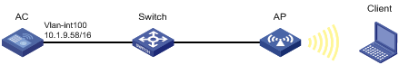
Configuration procedures
1. Create VLAN 100.
<AC> system-view
[AC] vlan 100
[AC-vlan100] quit
2. Create VLAN-interface 100 and assign it an IP address.
[AC] interface vlan-interface 100
[AC-Vlan-interface100] ip address 10.1.9.58 16
[AC-Vlan-interface100] quit
3. Create the manual AP ap1, and specify the AP model and serial ID.
[AC] wlan ap ap1 model WA536-WW
[AC-wlan-ap-ap1] serial-id 219801A1NQB117012935
[AC-wlan-ap-ap1] quit
4. Configure a service template and bind it to the AP radio:
# Create the service template service1, set the SSID to trade-off, assign clients coming online through the service template to VLAN 100, and enable the service template.
[AC] wlan service-template service1
[AC-wlan-st-service1] ssid trade-off
[AC-wlan-st-service1] vlan 100
[AC-wlan-st-service1] service-template enable
[AC-wlan-st-service1] quit
# Set the working channel to channel 157 for radio 1 of the AP.
[AC-wlan-ap-ap1] radio 1
[AC-wlan-ap-ap1-radio-1] channel 157
# Bind service template service1 to radio 1.
[AC-wlan-ap-ap1-radio-1] radio enable
[AC-wlan-ap-ap1-radio-1] service-template service1
[AC-wlan-ap-ap1-radio-1] quit
[AC-wlan-ap-ap1] quit
Verifying the configuration
# Verify that the SSID is trade-off, and the service template is enabled.
[AC] display wlan service-template verbose
Service template name : service1
Description : Not configured
SSID : trade-off
SSID-hide : Disabled
User-isolation : Disabled
Service template status : Enabled
Maximum clients per BSS : Not configured
Frame format : Dot3
Seamless roam status : Disabled
Seamless roam RSSI threshold : 50
Seamless roam RSSI gap : 20
VLAN ID : 100
AKM mode : Not configured
Security IE : Not configured
Cipher suite : Not configured
TKIP countermeasure time : 0 s
PTK life time : 43200 s
PTK rekey : Enabled
GTK rekey : Enabled
GTK rekey method : Time-based
GTK rekey time : 86400 s
GTK rekey client-offline : Disabled
User authentication mode : Bypass
Intrusion protection : Disabled
Intrusion protection mode : Temporary-block
Temporary block time : 180 sec
Temporary service stop time : 20 sec
Fail VLAN ID : Not configured
802.1X handshake : Disabled
802.1X handshake secure : Disabled
802.1X domain : my-domain
MAC-auth domain : Not configured
Max 802.1X users per BSS : 4096
Max MAC-auth users per BSS : 4096
802.1X re-authenticate : Enabled
Authorization fail mode : Online
Accounting fail mode : Online
Authorization : Permitted
Key derivation : SHA1
PMF status : Disabled
Hotspot policy number : Not configured
Forwarding policy status : Disabled
Forwarding policy name : Not configured
Forwarder : AC
FT status : Disabled
QoS trust : Port
QoS priority : 0
# Associate the client with the AP. (Details not shown.)
# Verify that the client can access the WLAN.
[AC] display wlan client service-template service1
Total number of clients: 1
MAC address Username AP name RID IP address IPv6 address VLAN
0023-8933-223b N/A ap1 1 3.0.0.3 100
Whitelist configuration example
Network requirements
As shown in Figure 21, configure the whitelist to permit only the client whose MAC address is 0000-000f-1211 to access the WLAN.

Configuration procedures
# Add the MAC address 0000-000f-1211 to the whitelist.
[AC] wlan whitelist mac-address 0000-000f-1211
Verifying the configuration
# Verify that the MAC address 0000-000f-1211 is in the whitelist.
Total number of clients: 1
MAC addresses:
0000-000f-1211
Static blacklist configuration example
Network requirements
As shown in Figure 22, configure the static blacklist to forbid the client whose MAC address is 0000-000f-1211 to access the WLAN.
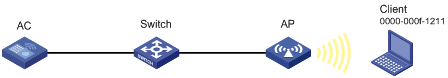
Configuration procedures
# Add the MAC address 0000-000f-1211 to the static blacklist.
[AC] wlan static-blacklist mac-address 0000-000f-1211
Verifying the configuration
# Verify that the MAC address 0000-000f-1211 is in the static blacklist.
[AC] display wlan blacklist static
Total number of clients: 1
MAC addresses:
0000-000f-1211
Configuring WLAN security
Overview
The original IEEE 802.11 is a Pre Robust Security Network Association (Pre-RSNA) mechanism. This mechanism is vulnerable to security attacks such as key exposure, traffic interception, and tampering. To enhance WLAN security, IEEE 802.11i (the RSNA mechanism) was introduced. You can select either of the Pre-RSNA or RSNA as needed to secure your WLAN.
IEEE 802.11i encrypts only WLAN data traffic. Unencrypted WLAN management frames are open to attacks on secrecy, authenticity, and integrity. IEEE 802.11w offers management frame protection based on the 802.11i framework to prevent attacks such as forged de-authentication and disassociation frames.
Pre-RSNA mechanism
The pre-RSNA mechanism uses the open system and shared key algorithms for authentication and uses WEP for data encryption. WEP uses the stream cipher RC4 for confidentiality and supports key sizes of 40 bits (WEP40), 104 bits (WEP104), and 128 bits (WEP128).
Open system authentication
Open system authentication is the default and simplest authentication algorithm. Any client that requests authentication by using this algorithm can pass the authentication.
Open system authentication uses the following process:
1. The client sends an authentication request to the AP.
2. The AP sends an authentication response to the client after the client passes the authentication.
Figure 23 Open system authentication process
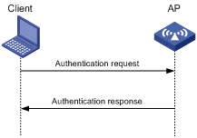
Shared key authentication
Shared key authentication uses a WEP key for the AP and client to complete authentication.
Shared key authentication uses the following process:
1. The client sends an authentication request to the AP.
2. The AP randomly generates a challenge text and sends it to the client.
3. The client uses the WEP key to encrypt the challenge text and sends it to the AP.
4. The AP uses the WEP key to decrypt the challenge text and compares the decrypted challenge text with the original challenge text. If they are identical, the client passes the authentication. If they are not, the authentication fails.
Figure 24 Shared key authentication process
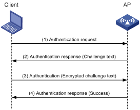
RSNA mechanism
|
|
IMPORTANT: RSNA requires open system authentication for link layer authentication. |
The RSNA mechanism includes WPA and RSN security modes. RSNA provides the following features:
· 802.1X and PSK authentication and key management (AKM) for authenticating user integrity and dynamically generating and updating keys.
? 802.1X—802.1X performs user authentication and generates the pairwise master key (PMK) during authentication. The client and AP use the PMK to generate the pairwise transient key (PTK).
? Private PSK—The MAC address of the client is used as the PSK to generate the PMK. The client and AP use the PMK to generate the PTK.
? PSK—The PSK is used to generate the PMK. The client and AP use the PMK to generate the PTK.
· Temporal key integrity Protocol (TKIP) and Counter Mode CBC-MAC Protocol (CCMP) mechanisms for encrypting data.
Authentication
802.1X authentication is more secure than PSK authentication. For more information about 802.1X authentication, see "Configuring WLAN user access authentication."
PSK authentication requires the same PSK to be configured for both an AP and a client. PSK integrity is verified during the four-way handshake. If PTK negotiation succeeds, the client passes the authentication.
Key management
Key management defines how to generate and update the PTK and group temporary key (GTK). The PTK is used in unicast and the GTK is used in multicast and broadcast.
PTK and GTK
· PTK structure
![]()
? EAPOL-Key Confirmation Key (KCK) is used to verify the integrity of an EAPOL-Key frame.
? EAPOL-Key Encryption Key (KEK) is used to encrypt the key data in the EAPOL-Key frame.
? Temporal Key (TK) is used to encrypt unicast packets.
· The GTK includes the TK and other fields. The TK is used to encrypt multicast and broadcast packets.
EAPOL-Key packet
The IEEE 802.11i protocol uses EAPOL-Key packets during key negotiation.
Figure 25 EAPOL-Key structure
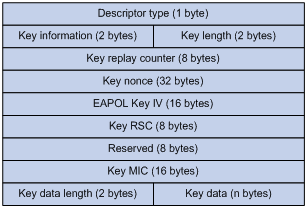
Table 23 EAPOL-Key field description
|
Field |
Description |
|
Descriptor type |
Specifies the network type: · WPA network. · RSN network. |
|
Key information |
For more information about this field, see Table 24. |
|
Key length |
Length of the key. |
|
Key replay counter |
Records the total number of GTK updates to prevent replay attacks. The AP sets this field to 0 at the beginning of the negotiation and increments the value on each successive EAPOL-Key frame. The client records this field from the last valid EAPOL-Key frame that it received if this field is greater than the field recorded previously. EAPOL-Key frame retransmission is required in the following situations: · The field received by the client is smaller than or equal to the field recorded by the client. · The field received by the AP is not equal to the field recorded on the AP. If the retransmission attempts exceed the maximum number, the AP disconnects the client. |
|
Key nonce |
Random value used to generate the PTK. |
|
EAPOL Key IV |
Encrypts the TKIP. This field is valid only when the encryption type is not CCMP. |
|
Key RSC |
Records the total number of multicast packets or broadcast packets to prevent replay attacks. The AP increments the value of this field on transmission of each multicast or broadcast packet. |
|
Reserved |
Reserved field. |
|
Key MIC |
Message integrity check. |
|
Key data length |
Length of the key data. |
|
Key data |
Data to be transmitted, such as the GTK and pairwise master key identifier (PMKID). |
Figure 26 Key information structure
![]()
Table 24 Key information description
|
Field |
Description |
|
Key Descriptor Version |
3-bit key version: · 1—Non-CCMP key. · 2—CCMP key. |
|
Key Type |
1-bit key type: · 0—Multicast negotiation key. · 1—Unicast negotiation key. |
|
Reserved |
2-bit field reserved. The sender sets this field to 0, and the receiver ignores this field. |
|
Install |
1-bit key installation field. If the Key Type field is 1, this field is 0 or 1. · 0—The AP does not request the client to install the TK. · 1—The AP requests the client to install the TK. If the Key type field is 0, the sender sets this field to 0, and the receiver ignores this field. |
|
Key Ack |
1-bit key acknowledgment field. The value 1 indicates that the AP requests an acknowledgement from the client. |
|
Key MIC |
Message integrity check. If this field is 1, the generated MIC must be included in the Key MIC field of the EAPOL-key frame. |
|
Secure |
1-bit key status. The value 1 indicates that the key has been generated. |
|
Error |
1-bit MIC check status. The value 1 indicates that a MIC failure has occurred. The client sets this field to 1 when the Request field is 1. |
|
Request |
1-bit request used by the client to request the AP to initiate the four-way handshake or multi-cast handshake in a MIC failure report. |
|
Encrypted Key Data |
1-bit key data encryption status. The value 1 indicates that the key data is encrypted. |
|
Reserved |
3-bit reserved field. The sender sets this field to 0, and the receiver ignores this field. |
WPA key negotiation
WPA uses EAPOL-Key packets in the four-way handshake to negotiate the PTK, and in the two-way handshake to negotiate the GTK.
Figure 27 WPA key negotiation process
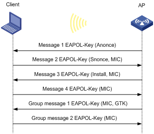
WPA key negotiation uses the following process:
1. The AP sends the client EAPOL-Key message 1 that contains a random value ANonce.
2. The client performs the following operations:
a. Uses the random value SNonce, ANonce, and PMK to generate a PTK by using the key derivation function (KDF).
b. Uses the KCK in the PTK to generate the MIC.
c. Returns EAPOL-Key message 2 that contains the SNonce and MIC.
3. The AP performs the following operations:
a. Uses the SNonce, ANonce, and PMK to generate a PTK by using the KDF.
b. Uses the KCK in the PTK to generate the MIC.
c. Compares the received MIC with the local MIC.
d. Returns EAPOL-Key message 3 that contains the PTK installation request tag and MIC if the two MICs are the same.
4. The client performs the following operations:
a. Compares the received MIC with the local MIC.
b. Installs the PTK and returns EAPOL-Key message 4 that contains the MIC if the two MICs are the same.
5. The AP performs the following operations:
a. Compares the received MIC with the local MIC.
b. Installs the PTK and generates a GTK with the GMK and MAC address of the AP by using the KDF if the two MICs are the same.
c. Returns EAPOL-Key group message 1 that contains the GTK and MIC.
6. The client performs the following operations:
a. Installs the GTK if the two MICs are the same.
b. Returns EAPOL-Key group message 2 that contains the MIC.
7. The AP performs the following operations:
a. Compares the received MIC with the local MIC.
b. Installs the GTK if the MICs are the same.
RSN key negotiation
RSN uses EAPOL-Key packets in the four-way handshake to negotiate the PTK and the GTK.
Figure 28 RSN key negotiation process
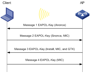
RSN key negotiation uses the following process:
1. The AP sends the client EAPOL-Key message 1 that contains a random value ANonce.
2. The client performs the following operations:
a. Uses the random value SNonce, ANonce, and PMK to generate a PTK by using the KDF.
b. Uses the KCK in the PTK to generate the MIC.
c. Returns EAPOL-Key message 2 that contains the SNonce and MIC.
3. The AP performs the following operations:
a. Uses the SNonce, ANonce, and PMK to generate a PTK by using the KDF.
b. Uses the KCK in the PTK to generate the MIC.
c. Compares the received MIC with the local MIC.
d. Generates a GTK with the random GMK and MAC address of the AP by using the KDF if the two MICs are the same.
e. Returns EAPOL-Key message 3 that contains the key installation request tag, MIC, and GTK.
4. The client performs the following operations:
a. Compares the received MIC with the local MIC.
b. Installs the PTK and GTK if the two MICs are the same.
c. Returns EAPOL-Key message 4 that contains the MIC.
5. The AP performs the following operations:
a. Compares the received MIC with the local MIC.
b. Installs the PTK and GTK if the two MICs are the same.
Key updates
Key updates enhance WLAN security. Key updates include PTK updates and GTK updates.
· PTK updates—Updates for the unicast keys using the four-way handshake negotiation.
· GTK updates—Updates for the multicast keys using the two-way handshake negotiation.
Cipher suites
TKIP
TKIP and WEP both use the RC4 algorithm. You can change the cipher suite from WEP to TKIP by updating the software without changing the hardware. TKIP has the following advantages over WEP:
· TKIP provides longer initialization vectors (IVs) to enhance encryption security. Compared with WEP encryption, TKIP encryption uses the 128-bit RC4 encryption algorithm, and increases the length of IVs from 24 bits to 48 bits.
· TKIP allows for dynamic key negotiation to avoid static key configuration. TKIP dynamic keys cannot be easily deciphered.
· TKIP offers MIC and countermeasures. If a packet has been tampered with, it will fail the MIC. If two packets fail the MIC in a period, the AP automatically takes countermeasures by stopping providing services in a period to prevent attacks.
CCMP
CCMP is based on the Counter-Mode/CBC-MAC (CCM) of the Advanced Encryption Standard (AES) encryption algorithm.
CCMP contains a dynamic key negotiation and management method. Each client can dynamically negotiate a key suite, which can be updated periodically to further enhance the security of the CCMP cipher suite. During the encryption process, CCMP uses a 48-bit packet number (PN) to make sure each encrypted packet uses a different PN. This improves WLAN security.
Management frame protection
The management frame protection service protects a set of robust management frames, such as de-authentication, disassociation, and some robust action frames. Management frame protection uses the PTK to encrypt unicast management frames and provides secrecy, integrity, and replay protection. It uses the Broadcast Integrity Protocol (BIP) to provide integrity and replay protection for broadcast and multicast management frames.
The security association (SA) query mechanism is used to enhance security if the AP and client negotiate to use management frame protection. SA queries include active SA queries and passive SA queries.
· Active SA query
As shown in Figure 29, active SA query uses the following process:
a. The client sends an association or reassociation request to the AP.
b. Upon receiving the request, the AP sends a response to inform the client that the request is denied and the client can associate at a later time. The response contains the association comeback time.
c. The AP sends an SA query request to verify the status of the client:
- If the AP receives an SA query response within the timeout time, it determines that the client is online.
- If the AP does not receive an SA query response within the timeout time, it sends another SA query request. If the AP receives an SA query response within the retransmission time, it determines that the client is online. The AP does not respond to any association or reassociation requests from the client until the association comeback time times out.
- If the AP does not receive an SA query response within the retransmission time, it determines that the client is offline and allows the client to reassociate.
Figure 29 Active SA query process
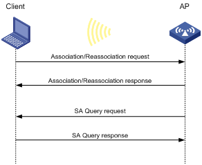
· Passive SA query
As shown in Figure 30, passive SA query uses the following process:
a. The client triggers the SA query process upon receiving an unencrypted disassociation or deauthentication frame.
b. The client sends an SA query request to the AP.
c. The AP sends an SA query response to the client:
- If the client receives the response, the client determines that the AP is online and does not process the disassociation or deauthentication frame.
- If the client does not receive a response, the client determines that the AP is offline and disassociates with the AP.
Figure 30 Passive SA query process
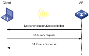
Dynamic WEP mechanism
|
|
IMPORTANT: The dynamic WEP mechanism uses open system authentication for link layer authentication. |
IEEE 802.11 provides the dynamic WEP mechanism to ensure that each user uses a private WEP key. For unicast communications, the mechanism uses the WEP key negotiated by the client and server during 802.1X authentication. For multicast and broadcast communications, the mechanism uses the configured WEP key. If you do not configure a WEP key, the AP randomly generates a WEP key for broadcast and multicast communications.
After the client passes 802.1X authentication, the AP sends the client an RC4-EAPOL packet that contains the unicast WEP key ID, and the multicast and broadcast WEP key and key ID. The unicast WEP key ID is 4.
Protocols and standards
· IEEE Standard for Information technology—Telecommunications and information exchange between systems—Local and metropolitan area networks—Specific requirements—2004
· WI-FI Protected Access—Enhanced Security Implementation Based On IEEE P802.11i Standard-Aug 2004
· Information technology—Telecommunications and information exchange between systems—Local and metropolitan area networks—Specific requirements—802.11, 1999
· IEEE Standard for Local and metropolitan area networks "Port-Based Network Access Control" 802.1X™-2004
· 802.11i IEEE Standard for Information technology—Telecommunications and information exchange between systems—Local and metropolitan area networks—Specific requirements
· 802.11w IEEE Standard for Information technology—Telecommunications and information exchange between systems—Local and metropolitan area networks—Specific requirements
WLAN security configuration task lists
|
IMPORTANT: · RSNA requires open system authentication for link layer authentication. · The dynamic WEP mechanism requires 802.1X authentication for user access authentication. · The AKM mode, security IE, and cipher suite must be configured for RSNA networks. · Management frame protection takes effect only for a network that uses the RSNA mechanism and is configured with the CCMP cipher suite and RSN security information element. |
To configure the pre-RSNA mechanism, perform the following tasks:
|
Tasks at a glance |
|
(Required.) Setting the cipher suite |
|
(Required.) Setting the WEP key |
|
(Optional.) Enabling SNMP notifications for WLAN security |
To configure the RSNA mechanism, perform the following tasks:
|
Tasks at a glance |
|
(Required.) Configuring the AKM mode |
|
(Required.) Setting the security information element |
|
(Required.) Setting the cipher suite |
|
(Optional.) Setting the PSK |
|
(Optional.) Setting the KDF |
|
(Optional.) Configuring GTK update |
|
(Optional.) Setting the PTK lifetime |
|
(Optional.) Setting the TKIP MIC failure hold time |
|
(Optional.) Setting the WEP key |
|
(Optional.) Configuring management frame protection |
|
(Optional.) Enabling SNMP notifications for WLAN security |
To configure the dynamic WEP mechanism, perform the following tasks:
|
Tasks at a glance |
|
(Optional.) Setting the cipher suite |
|
(Optional.) Setting the WEP key |
|
(Required.) Enabling the dynamic WEP mechanism |
|
(Optional.) Enabling SNMP notifications for WLAN security |
|
|
NOTE: · If a WEP key is configured, the dynamic WEP mechanism uses the configured WEP key as the multicast and broadcast WEP key. The negotiated unicast WEP has an ID of 4 and uses the cipher suite length setting. · If no WEP key is configured, the length for both dynamic WEP keys is 104 bits. The negotiated unicast WEP key has an ID of 4. The generated multicast and broadcast WEP key has an ID of 1. |
Configuring the AKM mode
Each of the following AKM modes must be used with a specific authentication mode:
· 802.1X AKM—802.1X authentication mode.
· Private PSK AKM—MAC authentication mode.
· PSK AKM—MAC or bypass authentication mode.
· WiFi alliance anonymous 802.1X AKM—802.1X authentication mode.
To configure the AKM mode:
|
Step |
Command |
Remarks |
|
1. Enter system view. |
system-view |
N/A |
|
2. Enter WLAN service template view. |
wlan service-template service-template-name |
N/A |
|
3. Configure the AKM mode. |
akm mode { dot1x | private-psk | psk | anonymous-dot1x } |
By default, no AKM mode is configured. |
Setting the security information element
|
Step |
Command |
Remarks |
|
1. Enter system view. |
system-view |
N/A |
|
2. Enter WLAN service template view. |
wlan service-template service-template-name |
N/A |
|
3. Set the security IE. |
security-ie { osen | rsn | wpa } |
By default, no security IE is set. |
Setting the cipher suite
Cipher suites include:
· WEP (WEP40, WEP104, or WEP128).
· CCMP.
· TKIP.
To set the cipher suite:
|
Step |
Command |
Remarks |
|
1. Enter system view. |
system-view |
N/A |
|
2. Enter WLAN service template view. |
wlan service-template service-template-name |
N/A |
|
3. Set the cipher suite. |
cipher-suite { ccmp | tkip | wep40 | wep104 | wep128 } |
By default, no cipher suite is set. You cannot set both WEP 128 and CCMP or both WEP 128 and TKIP. |
Setting the PSK
The PSK must be set if the AKM mode is PSK. If you configure the PSK when the AKM mode is 802.1X, the WLAN service template can be enabled but the PSK configuration does not take effect.
To set the PSK:
|
Step |
Command |
Remarks |
|
1. Enter system view. |
system-view |
N/A |
|
2. Enter WLAN service template view. |
wlan service-template service-template-name |
N/A |
|
3. Set the PSK. |
preshared-key { pass-phrase | raw-key } { cipher | simple } key |
By default, no PSK is set. |
Setting the KDF
KDFs are used by RSNA networks to generate PTKs and GTKs. KDFs include HMAC-SHA1 and HMAC-SHA256 algorithms. The HMAC-SHA256 algorithm is more secure than the HMAC-SHA1 algorithm.
To set the KDF:
|
Step |
Command |
Remarks |
|
1. Enter system view. |
system-view |
N/A |
|
2. Enter WLAN service template view. |
wlan service-template service-template-name |
N/A |
|
3. Set the KDF. |
key-derivation { sha1 | sha256 | sha1-and-sha256 } |
By default, the HMAC-SHA1 algorithm is set. |
Configuring GTK update
The system generates the GTK during key negotiation if the AKM, security IE, and cipher suite are configured. This feature updates the GTK to enhance key security based on the following updating modes:
· Time-based—The GTK is updated at the specified interval.
· Packet-based—The GTK is updated after the specified number of packets is sent.
· Offline-triggered—The GTK is updated when a client in the basic service set (BSS) goes offline.
To configure GTK update:
|
Step |
Command |
Remarks |
|
1. Enter system view. |
system-view |
N/A |
|
2. Enter WLAN service template view. |
wlan service-template service-template-name |
N/A |
|
3. Enable GTK update. |
gtk-rekey enable |
By default, GTK update is enabled. |
|
4. (Optional.) Configure a GTK update method. |
gtk-rekey method { packet-based [ packet ] | time-based [ time ] } |
By default, the GTK is updated at an interval of 85400 seconds. The default packet quantity is 10000000 for packet-based GTK update. |
|
5. (Optional.) Enable the offline-triggered GTK update. |
gtk-rekey client-offline enable |
By default, offline-triggered GTK update is disabled. |
Setting the PTK lifetime
About the PTK lifetime
The system generates the PTK during key negotiation when the AKM, security IE, and cipher suite are configured. This feature updates the PTK after the PTK lifetime expires.
Procedure
|
Step |
Command |
Remarks |
|
1. Enter system view. |
system-view |
N/A |
|
2. Enter WLAN service template view. |
wlan service-template service-template-name |
N/A |
|
3. Enable PTK rekey. |
ptk-rekey enable |
By default, PTK rekey is enabled. |
|
4. Set the PTK lifetime. |
ptk-lifetime time |
By default, the PTK lifetime is 43200 seconds. |
Setting the TKIP MIC failure hold time
After configuring the TKIP, you can configure the TKIP MIC failure hold time. If the AP detects two MIC failures within the MIC failure hold time, it disassociates all clients for 60 seconds.
To set the TKIP MIC failure hold time:
|
Step |
Command |
Remarks |
|
1. Enter system view. |
system-view |
N/A |
|
2. Enter WLAN service template view. |
wlan service-template service-template-name |
N/A |
|
3. Set the TKIP MIC failure hold time. |
tkip-cm-time time |
By default, the TKIP MIC failure hold time is 0. The AP does not take any countermeasures. |
Setting the WEP key
The WEP key can be used to encrypt all packets for pre-RSNA networks and encrypt multicast packets for RSNA networks. If the WEP key is not set, a pre-RSNA network does not encrypt packets and an RSNA network uses the negotiated GTK to encrypt multicast packets.
To set the WEP key:
|
Step |
Command |
Remarks |
|
1. Enter system view. |
system-view |
N/A |
|
2. Enter WLAN service template view. |
wlan service-template service-template-name |
N/A |
|
3. Set the WEP key. |
wep key key-id { wep40 | wep104 | wep128 } { pass-phrase | raw-key } { cipher | simple } key |
By default, no WEP key is set. |
|
4. (Optional.) Apply the WEP key. |
wep key-id { 1 | 2 | 3 | 4 } |
By default, WEP key 1 is applied. Do not apply WEP key 4 if the dynamic WEP mechanism is enabled. |
Configuring management frame protection
Management frame protection takes effect only for a network that uses the RSNA mechanism and is configured with the CCMP cipher suite and RSN security information element.
If management frame protection is disabled, network access is available for all clients, but management frame protection is not performed. If management frame protection is enabled, the network access and management frame protection availability varies by management frame protection mode.
· Optional mode—Network access is available for all clients, but management frame protection is performed only for clients that support management frame protection.
· Mandatory mode—Network access and management frame protection are available only for clients that support management frame protection.
To configure management frame protection:
|
Step |
Command |
Remarks |
|
1. Enter system view. |
system-view |
N/A |
|
2. Enter WLAN service template view. |
wlan service-template service-template-name |
N/A |
|
3. Enable management frame protection. |
pmf { optional | mandatory } |
By default, management frame protection is disabled. |
|
4. Set the interval for sending SA query requests. |
pmf saquery retrytimeout timeout |
By default, the interval for sending SA query requests is 200 milliseconds. |
|
5. Set the maximum transmission attempts for SA query requests. |
pmf saquery retrycount count |
By default, the maximum retransmission attempt number is 4 for SA query requests. |
|
6. Set the association comeback time. |
pmf association-comeback time |
By default, the association comeback time is 1 second. |
Enabling the dynamic WEP mechanism
The dynamic WEP mechanism must be used with the 802.1X authentication mode.
To enable the dynamic WEP mechanism:
|
Step |
Command |
Remarks |
|
1. Enter system view. |
system-view |
N/A |
|
2. Enter WLAN service template view. |
wlan service-template service-template-name |
N/A |
|
3. Enable the dynamic WEP mechanism. |
wep mode dynamic |
By default, the dynamic WEP mechanism is disabled. |
Enabling SNMP notifications for WLAN security
To report critical WLAN security events to an NMS, enable SNMP notifications for WLAN security. For WLAN security event notifications to be sent correctly, you must also configure SNMP as described in Network Management and Monitoring Configuration Guide.
To enable SNMP notifications for WLAN security:
|
Step |
Command |
Remarks |
|
1. Enter system view. |
system-view |
N/A |
|
2. Enable SNMP notifications for WLAN security. |
snmp-agent trap enable wlan usersec |
By default, SNMP notifications are disabled for WLAN security. |
Displaying and maintaining WLAN security
Execute display commands in any view.
|
Task |
Command |
|
Display WLAN service template information. |
display wlan service-template [ service-template-name ] [ verbose ] For more information about this command, see "WLAN access commands." |
|
Display client information. |
display wlan client [ ap ap-name [ radio radio-id ] | mac-address mac-address | service-template service-template-name ] [ verbose ] For more information about this command, see "WLAN access commands." |
WLAN security configuration examples
Shared key authentication configuration example
Network requirements
As shown in Figure 31, the switch functions as a DHCP server to assign IP addresses to the AP and client. Configure shared key authentication to enable the client to access the network by using the WEP key 12345.
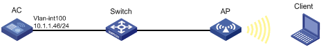
Configuration procedure
# Create a WLAN service template named service1.
<AC> system-view
[AC] wlan service-template service1
# Specify the SSID service for the service template.
[AC-wlan-st-service1] ssid service
# Specify the cipher suite wep40 and key 12345 for the service template service1, and apply the key with the ID 2.
[AC-wlan-st-service1] cipher-suite wep40
[AC-wlan-st-service1] wep key 2 wep40 pass-phrase simple 12345
[AC-wlan-st-service1] wep key-id 2
# Enable the service template service1.
[AC-wlan-st-service1] service-template enable
[AC-wlan-st-service1] quit
# Create an AP named ap1 and specify the model and serial ID.
[AC] wlan ap ap1 model WA536-WW
[AC-wlan-ap-ap1] serial-id 219801A1NQB117012935
# Bind the service template service1 to radio 1 of the AP, and enable radio 1.
[AC-wlan-ap-ap1] radio 1
[AC-wlan-ap-ap1-radio-1] service-template service1
[AC-wlan-ap-ap1-radio-1] radio enable
[AC-wlan-ap-ap1-radio-1] return
Verifying the configuration
# Use the display wlan service-template command to verify that the WLAN service template has been configured correctly.
<AC> display wlan service-template service1 verbose
Service template name : service1
Description : Not configured
SSID : service
SSID-hide : Disabled
User-isolation : Disabled
Service template status : Enabled
Maximum clients per BSS : 64
Frame format : Dot3
Seamless roam status : Disabled
Seamless roam RSSI threshold : 50
Seamless roam RSSI gap : 20
VLAN ID : 1
AKM mode : Not configured
Security IE : Not configured
Cipher suite : WEP40
WEP key ID : 2
TKIP countermeasure time : 0
PTK lifetime : 43200 sec
GTK rekey : Enabled
GTK rekey method : Time-based
GTK rekey time : 86400 sec
GTK rekey client-offline : Enabled
User authentication mode : Bypass
Intrusion protection : Disabled
Intrusion protection mode : Temporary-block
Temporary block time : 180 sec
Temporary service stop time : 20 sec
Fail VLAN ID : Not configured
802.1X handshake : Disabled
802.1X handshake secure : Disabled
802.1X domain : Not configured
MAC-auth domain : Not configured
Max 802.1X users per BSS : 4096
Max MAC-auth users per BSS : 4096
802.1X re-authenticate : Disabled
Authorization fail mode : Online
Accounting fail mode : Online
Authorization : Permitted
Key derivation : N/A
PMF status : Disabled
Hotspot policy number : Not configured
Forwarding policy status : Disabled
Forwarding policy name : Not configured
Forwarder : AC
FT status : Disabled
QoS trust : Port
QoS priority : 0
PSK authentication and bypass authentication configuration example
Network requirements
As shown in Figure 32, the switch functions as a DHCP server to assign IP addresses to the AP and client.
· Configure open system authentication and bypass authentication.
· Configure the client to use the preshared key 12345678 to access the network.

Configuration procedure
1. Create a WLAN service template named service1.
<AC> system-view
[AC] wlan service-template service1
2. Specify the SSID service for the service template.
[AC-wlan-st-service1] ssid service
3. Configure WLAN security for the service template service1:
# Configure PSK as the AKM mode and specify the plaintext key 12345678.
[AC-wlan-st-service1] akm mode psk
[AC-wlan-st-service1] preshared-key pass-phrase simple 12345678
# Configure CCMP as the cipher suite and WPA as the security IE.
[AC-wlan-st-service1] cipher-suite ccmp
[AC-wlan-st-service1] security-ie wpa
4. Enable the service template service1.
[AC-wlan-st-service1] service-template enable
[AC-wlan-st-service1] quit
5. Create an AP named ap1 and specify the model and serial ID.
[AC] wlan ap ap1 model WA536-WW
[AC-wlan-ap-ap1] serial-id 219801A1NQB117012935
6. Bind the service template service1 to radio 1 of the AP, and enable radio 1.
[AC-wlan-ap-ap1] radio 1
[AC-wlan-ap-ap1-radio-1] service-template service1
[AC-wlan-ap-ap1-radio-1] radio enable
[AC-wlan-ap-ap1-radio-1] return
Verifying the configuration
# Use the display wlan service-template command to verify that the WLAN service template has been configured correctly.
<AC> display wlan service-template service1 verbose
Service template name : service1
Description : Not configured
SSID : service
SSID-hide : Disabled
User-isolation : Disabled
Service template status : Enabled
Maximum clients per BSS : 64
Frame format : Dot3
Seamless roam status : Disabled
Seamless roam RSSI threshold : 50
Seamless roam RSSI gap : 20
VLAN ID : 1
AKM mode : PSK
Security IE : WPA
Cipher suite : CCMP
TKIP countermeasure time : 0
PTK lifetime : 43200 sec
GTK rekey : Enabled
GTK rekey method : Time-based
GTK rekey time : 86400 sec
GTK rekey client-offline : Enabled
User authentication mode : Bypass
Intrusion protection : Disabled
Intrusion protection mode : Temporary-block
Temporary block time : 180 sec
Temporary service stop time : 20 sec
Fail VLAN ID : Not configured
802.1X handshake : Disabled
802.1X handshake secure : Disabled
802.1X domain : Not configured
MAC-auth domain : Not configured
Max 802.1X users per BSS : 4096
Max MAC-auth users per BSS : 4096
802.1X re-authenticate : Disabled
Authorization fail mode : Online
Accounting fail mode : Online
Authorization : Permitted
Key derivation : N/A
PMF status : Disabled
Hotspot policy number : Not configured
Forwarding policy status : Disabled
Forwarding policy name : Not configured
Forwarder : AC
FT status : Disabled
QoS trust : Port
QoS priority : 0
PSK authentication and MAC authentication configuration example
Network requirements
As shown in Figure 33, the switch functions as a DHCP server to assign IP addresses to the AP and client.
· Configure open system authentication and MAC authentication so that the client can access the network by using the login username abc and password 123.
· Configure the client to use the preshared key 12345678 to access the network.
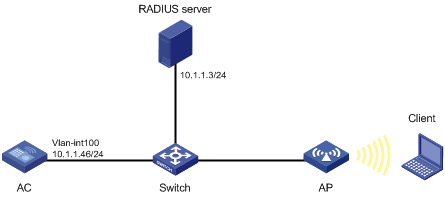
Configuration procedure
1. Configure the username abc and the password 123 on the RADIUS server and make sure the RADIUS server and AC can reach each other. (Details not shown.)
2. Create a WLAN service template named service1 with an SSID of service.
<AC> system-view
[AC] wlan service-template service1
[AC-wlan-st-service1] ssid service
3. Configure WLAN security for the service template service1:
# Configure PSK as the AKM mode and specify the plaintext key 12345678.
[AC-wlan-st-service1] akm mode psk
[AC-wlan-st-service1] preshared-key pass-phrase simple 12345678
# Configure CCMP as the cipher suite and WPA as the security IE.
[AC-wlan-st-service1] cipher-suite ccmp
[AC-wlan-st-service1] security-ie wpa
# Configure MAC authentication.
[AC-wlan-st-service1] client-security authentication-mode mac
4. Enable the service template service1.
[AC-wlan-st-service1] service-template enable
[AC-wlan-st-service1] quit
5. Configure a RADIUS scheme:
# Create a RADIUS scheme named radius1 and enter its view.
[AC] radius scheme radius1
# Specify the primary authentication server and accounting server.
[AC-radius-radius1] primary authentication 10.1.1.3 1812
[AC-radius-radius1] primary accounting 10.1.1.3 1813
# Set the shared keys for authentication and accounting to 12345678 in plaintext.
[AC-radius-radius1] key authentication simple 12345678
[AC-radius-radius1] key accounting simple 12345678
# Set the format for the usernames sent to the RADIUS server based on the RADIUS server configuration:
? Exclude domain names from the usernames sent to the RADIUS server.
[Device-radius-rs1] user-name-format without-domain
[Device-radius-rs1] quit
? Include domain names in the usernames sent to the RADIUS server.
[Device-radius-rs1] user-name-format with-domain
[Device-radius-rs1] quit
6. Create an ISP domain named dom1 and configure a RADIUS scheme for the ISP domain.
[AC] domain dom1
[AC-isp-dom1] authentication lan-access radius-scheme radius1
[AC-isp-dom1] authorization lan-access radius-scheme radius1
[AC-isp-dom1] accounting lan-access radius-scheme radius1
[AC-isp-dom1] quit
7. Configure the ISP domain dom1, username abc, and password 123 for the user.
[AC] mac-authentication mac domain dom1
[AC] mac-authentication user-name-format fixed account abc password simple 123
8. Create an AP named ap1 and specify the model and serial ID.
[AC] wlan ap ap1 model WA536-WW
[AC-wlan-ap-ap1] serial-id 219801A1NQB117012935
9. Bind the service template service1 to radio 1 of the AP, and enable radio 1.
[AC-wlan-ap-ap1] radio 1
[AC-wlan-ap-ap1-radio-1] service-template service1
[AC-wlan-ap-ap1-radio-1] radio enable
[AC-wlan-ap-ap1-radio-1] return
|
|
NOTE: For more information about the AAA and RADIUS commands in this section, see Security Command Reference. |
Verifying the configuration
# Use the display wlan service-template command to verify that the WLAN service template has been configured correctly.
<AC> display wlan service-template service1 verbose
Service template name : service1
Description : Not configured
SSID : service
SSID-hide : Disabled
User-isolation : Disabled
Service template status : Enabled
Maximum clients per BSS : 64
Frame format : Dot3
Seamless roam status : Disabled
Seamless roam RSSI threshold : 50
Seamless roam RSSI gap : 20
VLAN ID : 1
AKM mode : PSK
Security IE : WPA
Cipher suite : CCMP
TKIP countermeasure time : 0
PTK lifetime : 43200 sec
GTK rekey : Enabled
GTK rekey method : Time-based
GTK rekey time : 86400 sec
GTK rekey client-offline : Enabled
User authentication mode : MAC
Intrusion protection : Disabled
Intrusion protection mode : Temporary-block
Temporary block time : 180 sec
Temporary service stop time : 20 sec
Fail VLAN ID : Not configured
802.1X handshake : Disabled
802.1X handshake secure : Disabled
802.1X domain : Not configured
MAC-auth domain : Not configured
Max 802.1X users per BSS : 4096
Max MAC-auth users per BSS : 4096
802.1X re-authenticate : Disabled
Authorization fail mode : Online
Accounting fail mode : Online
Authorization : Permitted
Key derivation : N/A
PMF status : Disabled
Hotspot policy number : Not configured
Forwarding policy status : Disabled
Forwarding policy name : Not configured
Forwarder : AC
FT status : Disabled
QoS trust : Port
QoS priority : 0
802.1X AKM configuration example
Network requirements
As shown in Figure 34, the switch functions as a DHCP server to assign IP addresses to the AP and client.
· Configure open system authentication and 802.1X authentication so that the client can access the network by using the login username abcdef and password 123456.
· Configure 802.1X as the AKM mode.

Configuration procedure
1. Configure the username abcdef and the password 123456 on the RADIUS server and make sure the RADIUS server and AC can reach each other. (Details not shown.)
2. Configure the 802.1X client. (Details not shown.)
3. Create a WLAN service template named service1.
<AC> system-view
[AC] wlan service-template service1
4. Specify the SSID service for the service template.
[AC-wlan-st-service1] ssid service
5. Configure WLAN security for the service template service1:
# Configure 802.1X as the AKM mode.
[AC-wlan-st-service1] akm mode dot1x
# Configure CCMP as the cipher suite and WPA as the security IE.
[AC-wlan-st-service1] cipher-suite ccmp
[AC-wlan-st-service1] security-ie wpa
# Configure the 802.1X authentication mode.
[AC-wlan-st-service1] client-security authentication-mode dot1x
6. Enable the service template service1.
[AC-wlan-st-service1] service-template enable
[AC-wlan-st-service1] quit
7. Configure a RADIUS scheme:
# Create a RADIUS scheme named radius1 and enter its view.
[AC] radius scheme radius1
# Specify the primary authentication server and accounting server.
[AC-radius-radius1] primary authentication 10.1.1.3 1812
[AC-radius-radius1] primary accounting 10.1.1.3 1813
# Set the shared keys for authentication and accounting to 12345 in plaintext.
[AC-radius-radius1] key authentication simple 12345
[AC-radius-radius1] key accounting simple 12345
# Set the format for the usernames sent to the RADIUS server based on the RADIUS server configuration:
? Exclude domain names from the usernames sent to the RADIUS server.
[Device-radius-rs1] user-name-format without-domain
[Device-radius-rs1] quit
? Include domain names in the usernames sent to the RADIUS server.
[Device-radius-rs1] user-name-format with-domain
[Device-radius-rs1] quit
8. Create an ISP domain named dom1 and configure a RADIUS scheme for the ISP domain.
[AC] domain dom1
[AC-isp-dom1] authentication lan-access radius-scheme radius1
[AC-isp-dom1] authorization lan-access radius-scheme radius1
[AC-isp-dom1] accounting lan-access radius-scheme radius1
[AC-isp-dom1] quit
9. Configure dom1 as the default ISP domain.
[AC] domain default enable dom1
10. Create an AP named ap1 and specify the model and serial ID.
[AC] wlan ap ap1 model WA536-WW
[AC-wlan-ap-ap1] serial-id 219801A1NQB117012935
11. Bind the service template service1 to radio 1 of the AP, and enable radio 1.
[AC-wlan-ap-ap1] radio 1
[AC-wlan-ap-ap1-radio-1] service-template service1
[AC-wlan-ap-ap1-radio-1] radio enable
[AC-wlan-ap-ap1-radio-1] return
|
|
NOTE: For more information about the AAA and RADIUS commands in this section, see Security Command Reference. |
Verifying the configuration
# Use the display wlan service-template command to verify that the WLAN service template has been configured correctly.
<AC> display wlan service-template service1 verbose
Service template name : service1
Description : Not configured
SSID : service
SSID-hide : Disabled
User-isolation : Disabled
Service template status : Enabled
Maximum clients per BSS : 64
Frame format : Dot3
Seamless roam status : Disabled
Seamless roam RSSI threshold : 50
Seamless roam RSSI gap : 20
VLAN ID : 1
AKM mode : dot1x
Security IE : WPA
Cipher suite : CCMP
TKIP countermeasure time : 0
PTK lifetime : 43200 sec
GTK rekey : Enabled
GTK rekey method : Time-based
GTK rekey time : 86400 sec
GTK rekey client-offline : Enabled
User authentication mode : 802.1X
Intrusion protection : Disabled
Intrusion protection mode : Temporary-block
Temporary block time : 180 sec
Temporary service stop time : 20 sec
Fail VLAN ID : Not configured
802.1X handshake : Disabled
802.1X handshake secure : Disabled
802.1X domain : Not configured
MAC-auth domain : Not configured
Max 802.1X users per BSS : 4096
Max MAC-auth users per BSS : 4096
802.1X re-authenticate : Disabled
Authorization fail mode : Online
Accounting fail mode : Online
Authorization : Permitted
Key derivation : N/A
PMF status : Disabled
Hotspot policy number : Not configured
Forwarding policy status : Disabled
Forwarding policy name : Not configured
Forwarder : AC
FT status : Disabled
QoS trust : Port
QoS priority : 0
Management frame protection configuration example
Network requirements
As shown in Figure 35, the switch functions as a DHCP server to assign IP addresses to the AP and client.
· Configure the client to use the preshared key 12345678 to access the network.
· Configure the CCMP cipher suite, RSN security IE, and management frame protection.
Configuration procedure
1. Create a WLAN service template named service1.
<AC> system-view
[AC] wlan service-template service1
2. Specify the SSID service for the service template.
[AC-wlan-st-service1] ssid service
3. Configure management frame protection:
# Enable management frame protection in optional mode.
[AC-wlan-st-service1] pmf optional
# Set the KDF to sha1-and-sha256.
[AC-wlan-st-service1] key-derivation sha1-and-sha256
4. Configure the RSNA mechanism:
# Configure PSK as the AKM mode and specify the plaintext key 12345678.
[AC-wlan-st-service1] akm mode psk
[AC-wlan-st-service1] preshared-key pass-phrase simple 12345678
# Configure CCMP as the cipher suite and RSN as the security IE.
[AC-wlan-st-service1] cipher-suite ccmp
[AC-wlan-st-service1] security-ie rsn
5. Enable the service template service1.
[AC-wlan-st-service1] service-template enable
[AC-wlan-st-service1] quit
6. Create an AP named ap1 and specify the model and serial ID.
[AC] wlan ap ap1 model WA536-WW
[AC-wlan-ap-ap1] serial-id 219801A1NQB117012935
7. Bind the service template service1 to radio 1 of the AP, and enable radio 1.
[AC-wlan-ap-ap1] radio 1
[AC-wlan-ap-ap1-radio-1] service-template service1
[AC-wlan-ap-ap1-radio-1] radio enable
[AC-wlan-ap-ap1-radio-1] return
Verifying the configuration
# Use the display wlan service-template command to verify that the WLAN service template has been configured correctly.
<AC> display wlan service-template service1 verbose
Service template name : service1
Description : Not configured
SSID : service
SSID-hide : Disabled
User-isolation : Disabled
Service template status : Enabled
Maximum clients per BSS : 64
Frame format : Dot3
Seamless roam status : Disabled
Seamless roam RSSI threshold : 50
Seamless roam RSSI gap : 20
VLAN ID : 1
AKM mode : PSK
Security IE : RSN
Cipher suite : CCMP
TKIP countermeasure time : 0
PTK lifetime : 43200 sec
GTK rekey : Enabled
GTK rekey method : Time-based
GTK rekey time : 86400 sec
GTK rekey client-offline : Enabled
User authentication mode : Bypass
Intrusion protection : Disabled
Intrusion protection mode : Temporary-block
Temporary block time : 180 sec
Temporary service stop time : 20 sec
Fail VLAN ID : Not configured
802.1X handshake : Disabled
802.1X handshake secure : Disabled
802.1X domain : Not configured
MAC-auth domain : Not configured
Max 802.1X users per BSS : 4096
Max MAC-auth users per BSS : 4096
802.1X re-authenticate : Disabled
Authorization fail mode : Online
Accounting fail mode : Online
Authorization : Permitted
Key derivation : SHA1-AND-SHA256
PMF status : Optional
Hotspot policy number : Not configured
Forwarding policy status : Disabled
Forwarding policy name : Not configured
Forwarder : AC
FT status : Disabled
QoS trust : Port
QoS priority : 0
# Use the display wlan client verbose command to verify the management frame protection negotiation results after a 802.11w client comes online.
<AC> display wlan client verbose
Total number of clients: 1
MAC address : 5250-0012-0411
IPv4 address : 135.3.2.1
IPv6 address : N/A
Username : 11w
AID : 1
AP ID : 1
AP name : ap1
Radio ID : 1
SSID : service
BSSID : 1111-2222-3333
VLAN ID : 1
Sleep count : 147
Wireless mode : 802.11a
Channel bandwidth : 20MHz
SM power save : Disabled
Short GI for 20MHz : Not supported
Short GI for 40MHz : Not supported
STBC RX capability : Not supported
STBC TX capability : Not supported
LDPC RX capability : Not supported
Block Ack : TID 0 In
Support HT-MCS set : 0, 1, 2, 3, 4, 5, 6, 7,
8, 9, 10, 11, 12, 13, 14,
15
Supported rates : 1, 2, 5.5, 6, 9, 11,
12, 18, 24, 36, 48, 54 Mbps
QoS mode : WMM
Listen interval : 10
RSSI : 46
Rx/Tx rate : 39/65
Authentication method : Open system
Security mode : RSN
AKM mode : 802.1X
Cipher suite : CCMP
User authentication mode : 802.1X
Authorization ACL ID : N/A
Authorization user profile : N/A
Roam status : N/A
Key derivation : SHA1
PMF status : Enabled
Forwarding policy name : N/A
Online time : 0days 0hours 2minutes 56seconds
FT status : Inactive
Dynamic WEP mechanism configuration example
Network requirements
As shown in Figure 36, the switch functions as a DHCP server to assign IP addresses to the AP and client.
· Configure open system authentication and 802.1X authentication so that the client can access the network by using the login username abcdef and password 123456.
· Configure the dynamic WEP mechanism.
Configuration procedure
1. Configure the username abcdef and the password 123456 on the RADIUS server and make sure the RADIUS server and AC can reach each other. (Details not shown.)
2. Configure the 802.1X client. (Details not shown.)
3. Create a WLAN service template named service1.
<AC> system-view
[AC] wlan service-template service1
4. Specify the SSID service for the service template.
[AC-wlan-st-service1] ssid service
5. Enable the dynamic WEP mechanism.
[AC-wlan-st-service1] wep mode dynamic
6. Configure the 802.1X authentication mode.
[AC-wlan-st-service1] client-security authentication-mode dot1x
7. Enable the service template service1.
[AC-wlan-st-service1] service-template enable
[AC-wlan-st-service1] quit
8. Configure a RADIUS scheme:
# Create a RADIUS scheme named radius1 and enter its view.
[AC] radius scheme radius1
# Specify the primary authentication server and accounting server.
[AC-radius-radius1] primary authentication 10.1.1.3 1812
[AC-radius-radius1] primary accounting 10.1.1.3 1813
# Set the shared keys for authentication and accounting to 12345 in plaintext.
[AC-radius-radius1] key authentication simple 12345
[AC-radius-radius1] key accounting simple 12345
# Set the format for the usernames sent to the RADIUS server based on the RADIUS server configuration:
? Exclude domain names from the usernames sent to the RADIUS server.
[Device-radius-rs1] user-name-format without-domain
[Device-radius-rs1] quit
? Include domain names in the usernames sent to the RADIUS server.
[Device-radius-rs1] user-name-format with-domain
[Device-radius-rs1] quit
9. Create an ISP domain named dom1 and configure a RADIUS scheme for the ISP domain.
[AC] domain dom1
[AC-isp-dom1] authentication lan-access radius-scheme radius1
[AC-isp-dom1] authorization lan-access radius-scheme radius1
[AC-isp-dom1] accounting lan-access radius-scheme radius1
[AC-isp-dom1] quit
10. Configure dom1 as the default ISP domain.
[AC] domain default enable dom1
11. Create an AP named ap1 and specify the model and serial ID.
[AC] wlan ap ap1 model WA536-WW
[AC-wlan-ap-ap1] serial-id 219801A1NQB117012935
12. Bind the service template service1 to radio 1 of the AP, and enable radio 1.
[AC-wlan-ap-ap1] radio 1
[AC-wlan-ap-ap1-radio-1] service-template service1
[AC-wlan-ap-ap1-radio-1] radio enable
[AC-wlan-ap-ap1-radio-1] return
|
|
NOTE: For more information about the AAA and RADIUS commands in this section, see Security Command Reference. |
Verifying the configuration
# Use the display wlan service-template command to verify that the WLAN service template has been configured correctly.
<AC> display wlan service-template service1 verbose
Service template name : service1
Description : Not configured
SSID : service
SSID-hide : Disabled
User-isolation : Disabled
Service template status : Enabled
Maximum clients per BSS : 64
Frame format : Dot3
Seamless roam status : Disabled
Seamless roam RSSI threshold : 50
Seamless roam RSSI gap : 20
VLAN ID : 1
AKM mode : Not configured
Security IE : Not configured
Cipher suite : WEP104
TKIP countermeasure time : 0
PTK lifetime : 43200 sec
GTK rekey : Enabled
GTK rekey method : Time-based
GTK rekey time : 86400 sec
GTK rekey client-offline : Enabled
User authentication mode : 802.1X
Intrusionprotection : Disabled
Intrusionprotection mode : Temporary-block
Temporary block time : 180 sec
Temporaryservicestop time : 20 sec
Fail VLAN ID : Not configured
802.1X handshake : Disabled
802.1X handshake secure : Disabled
802.1X domain : Not configured
MAC-auth domain : Not configured
Max 802.1X users per BSS : 4096
Max MAC-auth users per BSS : 4096
802.1X re-authenticate : Disabled
Authorization fail mode : Online
Accounting fail mode : Online
Authorization : Permitted
Key derivation : N/A
PMF status : Disabled
Hotspot policy number : Not configured
Forwarding policy status : Disabled
Forwarding policy name : Not configured
Forwarder : AC
FT status : Disabled
QoS trust : Port
QoS priority : 0
Private PSK authentication and MAC authentication configuration example
Network requirements
As shown in Figure 37, the switch functions as a DHCP server to assign IP addresses to the AP and client.
· Configure the MAC authentication mode so that the client can access the network by using its MAC address as the login username and password.
· Configure the private PSK AKM mode so that the client can use its MAC address as the PSK.
Configuration procedure
1. Configure the username 00-23-12-45-67-7a and the password 00-23-12-45-67-7a on the RADIUS server and make sure the RADIUS server and AC can reach each other. (Details not shown.)
2. Create a WLAN service template named service1 with the SSID service.
<AC> system-view
[AC] wlan service-template service1
[AC-wlan-st-service1] ssid service
3. Configure WLAN security for the service template service1:
# Configure private PSK as the AKM mode.
[AC-wlan-st-service1] akm mode psk
# Configure CCMP as the cipher suite and WPA as the security IE.
[AC-wlan-st-service1] cipher-suite ccmp
[AC-wlan-st-service1] security-ie wpa
# Configure MAC authentication.
[AC-wlan-st-service1] client-security authentication-mode mac
4. Enable the service template service1.
[AC-wlan-st-service1] service-template enable
[AC-wlan-st-service1] quit
5. Configure a RADIUS scheme:
# Create a RADIUS scheme named radius1 and enter its view.
[AC] radius scheme radius1
# Specify the primary authentication server and accounting server.
[AC-radius-radius1] primary authentication 10.1.1.3 1812
[AC-radius-radius1] primary accounting 10.1.1.3 1813
# Set the shared keys for authentication and accounting to 12345678 in plaintext.
[AC-radius-radius1] key authentication simple 12345678
[AC-radius-radius1] key accounting simple 12345678
# Set the format for the usernames sent to the RADIUS server based on the RADIUS server configuration:
? Exclude domain names from the usernames sent to the RADIUS server.
[Device-radius-rs1] user-name-format without-domain
[Device-radius-rs1] quit
? Include domain names in the usernames sent to the RADIUS server.
[Device-radius-rs1] user-name-format with-domain
[Device-radius-rs1] quit
6. Create an ISP domain named dom1 and configure a RADIUS scheme for the ISP domain.
[AC] domain dom1
[AC-isp-dom1] authentication lan-access radius-scheme radius1
[AC-isp-dom1] authorization lan-access radius-scheme radius1
[AC-isp-dom1] accounting lan-access radius-scheme radius1
[AC-isp-dom1] quit
7. Configure the MAC address as the username and password for ISP domain dom1.
[AC] mac-authentication mac domain dom1
[AC] mac-authentication user-name-format mac-address with-hyphen lowercase
8. Create an AP named ap1 and specify the model and serial ID.
[AC] wlan ap ap1 model WA536-WW
[AC-wlan-ap-ap1] serial-id 219801A1NQB117012935
9. Bind the service template service1 to radio 1 of the AP, and enable radio 1.
[AC-wlan-ap-ap1] radio 1
[AC-wlan-ap-ap1-radio-1] service-template service1
[AC-wlan-ap-ap1-radio-1] radio enable
[AC-wlan-ap-ap1-radio-1] return
|
|
NOTE: For more information about the AAA and RADIUS commands in this section, see Security Command Reference. |
Verifying the configuration
# Use the display wlan service-template command to verify that the WLAN service template has been configured correctly.
<AC> display wlan service-template service1 verbose
Service template name : service1
Description : Not configured
SSID : service
SSID-hide : Disabled
User-isolation : Disabled
Service template status : Enabled
Maximum clients per BSS : 64
Frame format : Dot3
Seamless roam status : Disabled
Seamless roam RSSI threshold : 50
Seamless roam RSSI gap : 20
VLAN ID : 1
AKM mode : Private-PSK
Security IE : WPA
Cipher suite : CCMP
TKIP countermeasure time : 0
PTK lifetime : 43200 sec
GTK rekey : Enabled
GTK rekey method : Time-based
GTK rekey time : 86400 sec
GTK rekey client-offline : Enabled
User authentication mode : MAC
Intrusion protection : Disabled
Intrusion protection mode : Temporary-block
Temporary block time : 180 sec
Temporary service stop time : 20 sec
Fail VLAN ID : Not configured
802.1X handshake : Disabled
802.1X handshake secure : Disabled
802.1X domain : Not configured
MAC-auth domain : Not configured
Max 802.1X users per BSS : 4096
Max MAC-auth users per BSS : 4096
802.1X re-authenticate : Disabled
Authorization fail mode : Online
Accounting fail mode : Online
Authorization : Permitted
Key derivation : N/A
PMF status : Disabled
Hotspot policy number : Not configured
Forwarding policy status : Disabled
Forwarding policy name : Not configured
Forwarder : AC
FT status : Disabled
QoS trust : Port
QoS priority : 0
WLAN authentication overview
This chapter describes H3C implementation of WLAN authentication. WLAN authentication performs MAC-based network access control for WLAN clients to ensure access security.
WLAN authentication includes 802.1X authentication, MAC authentication, and OUI authentication.
Application scenarios
The authenticator authenticates the client to control access to the WLAN. As shown in Figure 38, either the AC or AP can be specified as the authenticator by using the client-security authentication-location command.
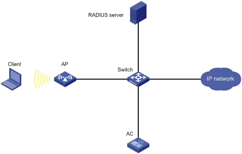
802.1X authentication
802.1X uses Extensible Authentication Protocol (EAP) to transport authentication information for the client, the authenticator, and the authentication server.
802.1X defines EAP over LAN (EAPOL) for passing EAP packets between the client and the authenticator over a WLAN. Between the authenticator and the authentication server, 802.1X delivers authentication information by using one of the following methods:
· Encapsulates EAP packets in RADIUS by using EAP over RADIUS (EAPOR), as described in "EAP relay."
· Extracts authentication information from the EAP packets and encapsulates the information in standard RADIUS packets, as described in "EAP termination."
For information about EAP packet encapsulation, see Security Configuration Guide.
802.1X authentication initiation
Both the client and the authenticator can initiate 802.1X authentication.
· Client initiation—After the client is associated with the authenticator, it sends an EAPOL-Start packet to the authenticator to initiate 802.1X authentication.
· Authenticator initiation—After the client is associated with the authenticator, the authenticator sends an EAP-Request/Identity packet to initiate the authentication. The authenticator retransmits the packet if no response has been received within the client timeout timer.
802.1X authentication process
The authenticator uses EAP relay or EAP termination to communicate with the RADIUS server.
EAP relay
In this mode, the authenticator uses EAPOR packets to send authentication information to the RADIUS server. The RADIUS server must support the EAP-Message and Message-Authenticator attributes, and must use the same authentication method as the client. For the authenticator, you only need to use the dot1x authentication-method eap command to enable EAP relay.
Figure 39 shows the basic 802.1X authentication process in EAP relay mode. In this example, EAP-MD5 is used.
|
|
NOTE: If the AP is specified as the authenticator, it uses the same authentication process as Figure 39 except that the AP handles the EAP and RADIUS packets. |
Figure 39 802.1X authentication process in EAP relay mode
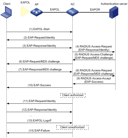
The following steps describe the 802.1X authentication process:
1. When a user launches the 802.1X client and enters a registered username and password, the 802.1X client sends an EAPOL-Start packet to the authenticator.
For information about the client and AP association, see "Configuring WLAN security."
2. The authenticator responds with an EAP-Request/Identity packet to request for the username.
3. The client sends the username in an EAP-Response/Identity packet to the authenticator.
4. The authenticator relays the EAP-Response/Identity packet in a RADIUS Access-Request packet to the authentication server.
5. The authentication server uses the username in the RADIUS Access-Request to search its user database. If a matching entry is found, the server uses a randomly generated challenge (EAP-Request/MD5-challenge) to encrypt the password in the entry. Then, the server sends the challenge in a RADIUS Access-Challenge packet to the authenticator.
6. The authenticator transmits the EAP-Request/MD5-Challenge packet to the client.
7. The client uses the received challenge to encrypt the password, and sends the encrypted password in an EAP-Response/MD5-Challenge packet to the authenticator.
8. The authenticator relays the EAP-Response/MD5-Challenge packet in a RADIUS Access-Request packet to the authentication server.
9. The authentication server compares the received encrypted password with the encrypted password it generated at step 5. If the two passwords are identical, the server considers the client valid and sends a RADIUS Access-Accept packet to the authenticator.
10. Upon receiving the RADIUS Access-Accept packet, the authenticator allows the client to access the network.
11. After the client comes online, the authenticator periodically sends handshake requests to examine whether the client is still online.
12. Upon receiving a handshake request, the client returns a response. If the client fails to return a response after a number of consecutive handshake attempts (two by default), the authenticator logs off the client. This handshake mechanism enables timely release of the network resources used by 802.1X clients that have abnormally gone offline.
13. The client sends an EAPOL-Logoff packet to request a logoff from the authenticator.
14. In response to the EAPOL-Logoff packet, the authenticator sends an EAP-Failure packet to the client.
EAP termination
In this mode, the authenticator performs the following operations:
1. Terminates the EAP packets received from the client.
2. Encapsulates the client authentication information in standard RADIUS packets.
3. Uses PAP or CHAP to communicate with the RADIUS server.
Figure 40 shows the basic 802.1X authentication process in EAP termination mode. In this example, CHAP authentication is used.
|
|
NOTE: If the AP is specified as the authenticator, it uses the same authentication process as Figure 40 except that the AP handles the EAP and RADIUS packets. |
Figure 40 802.1X authentication process in EAP termination mode
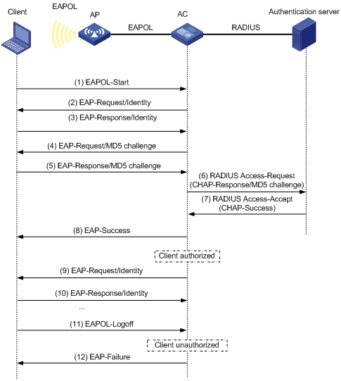
In EAP termination mode, the authentication device rather than the authentication server generates an MD5 challenge for password encryption. The authentication device then sends the MD5 challenge together with the username and encrypted password in a standard RADIUS packet to the RADIUS server.
MAC authentication
MAC authentication controls network access by authenticating source MAC addresses. The feature does not require any client software. Clients do not have to enter usernames or passwords for network access. The authenticator initiates a MAC authentication process when it detects an unknown source MAC address. If the MAC address passes authentication, the client can access authorized network resources. If the authentication fails, the authenticator marks the MAC address as a silent MAC address and rejects the client's access.
User account policies
User accounts are required for identifying clients. MAC authentication supports the following user account policies:
· One MAC-based user account for each client. The authenticator uses the unknown source MAC addresses in packets as the usernames and passwords of clients for MAC authentication.
· One shared user account for all clients. You specify one username and password, which are not necessarily a MAC address, for all MAC authentication clients on the authenticator. The username is a case-sensitive string of 1 to 55 characters which cannot include the at sign (@). The password can be a plaintext string of 1 to 63 characters or ciphertext string of 1 to 117 characters.
Authentication methods
You can perform MAC authentication on the authenticator (local authentication) or through a RADIUS server.
RADIUS authentication:
· MAC-based accounts—The authenticator sends the source MAC address of the packet as the username and password to the RADIUS server for authentication.
· A shared account—The authenticator sends the shared account username and password to the RADIUS server for authentication.
Local authentication:
· MAC-based accounts—The authenticator uses the source MAC address of the packet as the username and password to search the local account database for a match.
· A shared account—The authenticator uses the shared account username and password to search the local account database for a match.
For more information about configuring local authentication and RADIUS authentication, see Security Configuration Guide.
OUI authentication
OUI authentication examines the OUIs in the MAC addresses of clients. A client passes OUI authentication if the client's OUI matches one of the OUIs configured for the authenticator.
|
|
NOTE: An OUI is a 24-bit number that uniquely identifies a vendor, manufacturer, or organization. In MAC addresses, the first three octets are the OUI. |
Authentication modes
|
Authentication mode |
Working mechanism |
|
bypass (the default) |
Does not perform authentication. |
|
dot1x |
Performs 802.1X authentication only. |
|
mac |
Performs MAC authentication only. |
|
mac-then-dot1x |
Performs MAC authentication first, and then 802.1X authentication. If the client passes MAC authentication, 802.1X authentication is not performed. |
|
dot1x-then-mac |
Performs 802.1X authentication first, and then MAC authentication. If the client passes 802.1X authentication, MAC authentication is not performed. |
|
oui-then-dot1x |
Performs OUI authentication first, and then 802.1X authentication. If the client passes OUI authentication, 802.1X authentication is not performed. |
Intrusion protection
When the authenticator detects an association request from a client that fails authentication, intrusion protection is triggered. The feature takes one of the following predefined actions on the BSS where the request is received:
· temporary-block (default)—Adds the source MAC address of the request to the blocked MAC address list and drops the request packet. The client at a blocked MAC address cannot establish connections with the AP within a period. To set the period, use the client-security intrusion-protection timer temporary-block command.
· service-stop—Stops the BSS where the request is received until the BSS is enabled manually on the radio interface.
· temporary-service-stop—Stops the BSS where the request is received for a period. To set the period, use the client-security intrusion-protection timer temporary-service-stop command.
|
|
NOTE: Intrusion protection action is not supported in bypass mode. |
WLAN VLAN manipulation
VLAN authorization
You can specify authorization VLANs for a WLAN client to control the client's access to network resources. When the client passes 802.1X or MAC authentication, the authentication server assigns the authorization VLAN information to the authenticator. When the device acts as the authenticator, it can resolve server-assigned VLANs of the following formats:
· VLAN ID.
· VLAN name.
The VLAN name represents the VLAN description on the access device.
· VLAN group name.
For more information about VLAN groups, see Layer 2—LAN Switching Configuration Guide.
· Combination of VLAN IDs and VLAN names.
In the string, some VLANs are represented by their IDs, and some VLANs are represented by their names.
If the server assigns a group of VLANs, the access device selects and assigns a VLAN according to the VLAN ID format. Table 25 describes the VLAN selection and assignment rules for a group of authorization VLANs.
Table 25 VLAN selection and assignment for a group of authorization VLANs
|
Types of authorized VLANs |
VLAN selection and assignment rules |
|
· VLANs by IDs · VLANs by names |
The device selects the VLAN with the lowest ID from the group of VLANs. |
|
VLAN group name |
1. The device selects the VLAN that has the fewest number of online users. 2. If multiple VLANs have the same number of online 802.1X users, the device selects the VLAN with the lowest ID. |
|
|
NOTE: The device converts VLAN names and VLAN group names into VLAN IDs before it assigns a VLAN to the client. |
The device fails VLAN authorization for a client in the following situations:
· The device fails to resolve the authorization VLAN information.
· The server assigns a VLAN name to the device, but the device does not have any VLAN using the name.
· The server assigns a VLAN group name to the device, but the VLAN group does not exist or the VLAN group has not been assigned any VLANs.
Authorization VLAN information is used to control data forwarding, so they must be assigned by the device that forwards data traffic. VLAN assignment can be local VLAN assignment or remote VLAN assignment depending on whether the authenticator and the forwarding device are the same device.
· Local VLAN assignment—The authenticator and the forwarding device are the same device. After the authenticator obtains the authorization VLAN information, it resolves the information and assigns the VLAN.
· Remote VLAN assignment—The authenticator and the forwarding device are different devices. After the authenticator obtains the authorization VLAN information, it sends the information to the remote forwarding device. The forwarding device then resolves the information and assigns the VLAN.
For more information about VLANs, see Layer 2—LAN Switching Configuration Guide.
Auth-Fail VLAN
The WLAN Auth-Fail VLAN accommodates clients that have failed WLAN authentication because of the failure to comply with the organization security strategy. For example, the VLAN accommodates clients that have entered wrong passwords or usernames. The Auth-Fail VLAN does not accommodate WLAN clients that have failed authentication for authentication timeouts or network connection problems.
Clients in the Auth-Fail VLAN can access a limited set of network resources.
The authenticator reauthenticates a client in the Auth-Fail VLAN at the interval of 30 seconds.
· If the client passes the reauthentication, the authenticator assigns the client to the authorization VLAN. If no authorization VLAN is configured, the client is assigned to the initial VLAN.
· If the client fails the reauthentication, the client is still in the Auth-Fail VLAN.
Clients that use RSNA cannot be assigned to the Auth-Fail VLAN after they fail 802.1X authentication. The authenticator directly logs off the clients.
The Auth-Fail VLAN feature takes precedence over intrusion protection. When a client fails authentication, the Auth-Fail VLAN setting applies first. If no Auth-Fail VLAN is configured, the intrusion protection feature takes effect. If neither feature is configured, the authenticator directly logs off the client.
Using WLAN authentication with other features
ACL assignment
You can specify an ACL for an 802.1X client to control the client's access to network resources. After the client passes authentication, the authentication server assigns the ACL to the client for filtering traffic for this client. The authentication server can be on the local device that acts as the authenticator or on a RADIUS server. In either case, you must configure rules for the ACL on the authenticator. If the AP acts as the authenticator, you must configure the ACL rules on the AC.
To change the access control criteria for the client, you can use one of the following methods:
· Modify the ACL rules on the authenticator.
· Specify another ACL for the client on the authentication server.
For more information about ACLs, see ACL and QoS Configuration Guide.
User profile assignment
You can specify a user profile for an 802.1X client to control the client's access to network resources. After the client passes 802.1X authentication, the authentication server assigns the user profile to the client for filtering traffic. The authentication server can be on the local device that acts as the authenticator or on a RADIUS server. In either case, you must configure the user profile on the authenticator. If the AP acts as the authenticator, you must configure the user profile on the AC.
To change the client's access permissions, you can use one of the following methods:
· Modify the user profile configuration on the authenticator.
· Specify another user profile for the client on the authentication server.
For more information about user profiles, see Security Configuration Guide.
BYOD access control
This feature allows the RADIUS server to push different register pages and assign different authorization attributes to clients on different endpoint devices.
|
|
NOTE: This feature supports only IMC servers to act as the RADIUS server at the current version. |
The following process illustrates the BYOD access control for a WLAN client that passes 802.1X or MAC authentication:
1. The authenticator performs the following operations:
a. Obtains the Option 55 attribute from DHCP packets.
b. Delivers the Option 55 attribute to the RADIUS server.
On an IMC server, the Option 55 attribute will be delivered to UAM.
2. The BYOD-capable RADIUS server performs the following operations:
a. Uses the Option 55 attribute to identify endpoint device information including endpoint type, operating system, and vendor.
b. Sends a register page and assigns authorization attributes to the client according to the device information.
Configuring WLAN authentication
This chapter describes authenticator configuration for WLAN authentication.
Configuration prerequisites
Before you configure WLAN authentication, complete the following tasks:
· Configure an ISP domain and AAA scheme (local or RADIUS authentication) for WLAN clients.
· If local authentication is used, create local user accounts on the device (including usernames and passwords) and set the service type to lan-access.
· If RADIUS authentication is used, make sure the device and the RADIUS server can reach each other, and create user accounts on the RADIUS server. If you are using MAC-based accounts for MAC authentication clients, make sure the username and password for each account are the same as the MAC address of each client.
For more information, see Security Configuration Guide.
WLAN authentication configuration task list
Configuring global WLAN authentication parameters
Setting OUIs for OUI authentication
|
Step |
Command |
Remarks |
|
1. Enter system view. |
system-view |
N/A |
|
2. Set OUI values for OUI authentication. |
By default, no OUI value is set for OUI authentication. This step is required only for the oui-then-dot1x mode. You can set multiple OUIs. The device supports a maximum of 16 OUIs. |
Specifying 802.1X-supported domain name delimiters
|
Step |
Command |
Remarks |
|
1. Enter system view. |
system-view |
N/A |
|
2. Specify a set of domain name delimiters for 802.1X clients. |
dot1x domain-delimiter string |
By default, only the at sign (@) delimiter is supported. For more information about this command, see Security Command Reference. |
Enabling EAP relay or EAP termination for 802.1X
|
Step |
Command |
Remarks |
|
1. Enter system view. |
system-view |
N/A |
|
2. Enable EAP relay or EAP termination. |
dot1x authentication-method { chap | eap | pap } |
By default, the device performs EAP termination and uses CHAP to communicate with the RADIUS server. Specify the eap keyword to enable EAP relay. Specify the chap or pap keyword to enable CHAP-enabled or PAP-enabled EAP termination. For more information about this command, see Security Command Reference. |
|
|
NOTE: If EAP relay mode is used, the user-name-format command configured in RADIUS scheme view does not take effect. The device sends the authentication data from the client to the server without any modification. For information about the user-name-format command, see Security Command Reference. |
Setting the maximum number of 802.1X authentication request attempts
|
Step |
Command |
Remarks |
|
1. Enter system view. |
system-view |
N/A |
|
2. Set the maximum number of attempts for sending an 802.1X authentication request. |
dot1x retry max-retry-value |
The default setting is 2. For more information about this command, see Security Command Reference. |
Setting the 802.1X authentication timers
802.1X uses the following timers to control interactions with the client and the RADIUS server:
· Client timeout timer—Starts when the device sends an EAP-Request/MD5-Challenge packet to a client. If the device does not receive a response when this timer expires, it retransmits the request to the client. If the device has made the maximum transmission attempts without receiving a response, the client fails authentication. To set the maximum attempts, use the dot1x retry command.
· Server timeout timer—Starts when the device sends a RADIUS Access-Request packet to the authentication server. If the device does not receive a response when this timer expires, the device retransmits the request to the server.
· Handshake timer—Starts after a client passes authentication when the online user handshake is enabled. The device sends handshake messages to the client at every handshake interval. The device logs off the client if it does not receive any response from the client after the maximum handshake attempts. To set the maximum attempts, use the dot1x retry command.
· Periodic reauthentication timer—Starts after a client passes authentication when periodic online user reauthentication is enabled. The device reauthenticates the client at the configured interval. Any change to the timer takes effect only on clients that come online after the change.
In most cases, the default settings are sufficient. You can edit the timers, depending on the network conditions. The following are two examples:
· In a low-speed network, increase the client timeout timer.
· In a network with authentication servers of different performances, adjust the server timeout timer.
To set the 802.1X authentication timers:
|
Step |
Command |
Remarks |
|
1. Enter system view. |
system-view |
N/A |
|
2. Set the client timeout timer. |
dot1x timer supp-timeout supp-timeout-value |
The default setting is 30 seconds. For more information about this command, see Security Command Reference. |
|
3. Set the server timeout timer. |
dot1x timer server-timeout server-timeout-value |
The default setting is 100 seconds. For more information about this command, see Security Command Reference. |
|
4. Set the handshake timer. |
The default setting is 15 seconds. For more information about this command, see Security Command Reference. |
|
|
5. Set the periodic reauthentication timer. |
The default setting is 3600 seconds. For more information about this command, see Security Command Reference. |
Configuring the MAC authentication user account format
|
Step |
Command |
Remarks |
|
1. Enter system view. |
system-view |
N/A |
|
2. Configure the MAC authentication user account format. |
· Use one MAC-based user account for each
client: · Use one shared user account for all
clients: |
By default, the device uses the MAC address of a client as the username and password for MAC authentication. The MAC address is in the hexadecimal notation without hyphens, and letters are in lower case. For more information about this command, see Security Command Reference. |
Specifying a global MAC authentication domain
To implement different access policies for clients, you can specify ISP domains for MAC authentication clients globally or on a service template.
MAC authentication chooses an ISP domain for WLAN clients in the following order:
1. The domain specified on the service template.
2. The global MAC authentication domain specified in system view.
3. The default domain.
For information about ISP domains, see Security Configuration Guide.
To globally specify an ISP domain for MAC authentication clients:
|
Step |
Command |
Remarks |
|
1. Enter system view. |
system-view |
N/A |
|
2. Specify an ISP domain for MAC authentication clients. |
By default, no ISP domain is specified for MAC authentication clients in system view. For more information about this command, see Security Command Reference. |
Setting the MAC authentication server timeout timer
MAC authentication starts the server timeout timer when the device sends an authentication request to a RADIUS server. If the device does not receive any response from the RADIUS server within the timeout timer, the device regards the server unavailable. If the timer expires during MAC authentication, the client cannot access the network.
To set the MAC authentication server timeout timer:
|
Step |
Command |
Remarks |
|
1. Enter system view. |
system-view |
N/A |
|
2. Set the MAC authentication server timeout timer. |
mac-authentication timer server-timeout server-timeout-value |
The default setting is 100 seconds. For more information about this command, see Security Command Reference. |
Configuring service-specific WLAN authentication parameters
Setting the authentication mode
|
Step |
Command |
Remarks |
|
1. Enter system view. |
system-view |
N/A |
|
2. Enter service template view. |
N/A |
|
|
3. Set the authentication mode for WLAN clients. |
client-security authentication-mode { dot1x | dot1x-then-mac | mac | mac-then-dot1x | oui-then-dot1x } |
By default, the bypass mode applies. The device does not perform authentication. Clients can access the device directly. |
Specifying an EAP mode for 802.1X authentication
The EAP mode determines the EAP protocol provisions and packet format that the device uses to interact with clients.
802.1X supports the following EAP modes:
· extended—Requires the device to interact with clients according to the provisions and packet format defined by the H3C proprietary EAP protocol.
· standard—Requires the device to interact with clients according to the provisions and packet format defined by the standard EAP protocol.
Perform this task only when an IMC server is used as the RADIUS server.
To specify an EAP mode for 802.1X authentication:
|
Step |
Command |
Remarks |
|
1. Enter system view. |
system-view |
N/A |
|
2. Enter service template view. |
wlan service-template service-template-name |
N/A |
|
3. Specify an EAP mode for 802.1X authentication. |
dot1x eap { extended | standard } |
By default, the EAP mode is standard for 802.1X authentication. Specify the extended keyword for iNode clients, and specify the standard keyword for other clients. |
Specifying the authenticator for WLAN clients
You can specify the AC or AP to act as the authenticator to perform local or RADIUS-based authentication for WLAN clients.
For a successful authentication, the authenticator cannot be the AP if the AC is configured to forward client data traffic. For information about specifying the device for forwarding client data traffic, see "Configuring WLAN access."
To specify the authenticator for WLAN clients:
|
Step |
Command |
Remarks |
|
1. Enter system view. |
system-view |
N/A |
|
2. Enter service template view. |
wlan service-template service-template-name |
N/A |
|
3. Specify the authenticator for WLAN clients. |
By default, the AC acts as the authenticator to authenticate WLAN clients. |
Ignoring 802.1X or MAC authentication failures
Overview
This feature applies to the following clients:
· Clients that perform 802.1X authentication.
This feature enables the device to ignore the 802.1X authentication failures and allow clients that have failed 802.1X authentication to come online.
· Clients that perform both RADIUS-based MAC authentication and portal authentication.
Typically, a WLAN client must pass MAC authentication and portal authentication in turn to access network resources. The client provides username and password each time portal authentication is performed.
This feature simplifies the authentication process for a client as follows:
? If the RADIUS server already records the client's MAC authentication information, the client passes MAC authentication. The device allows the client to access network resources without performing portal authentication.
? If the RADIUS server does not record the client's MAC authentication information, the client fails MAC authentication. The device ignores the MAC authentication failures and performs portal authentication for the client. If the client passes portal authentication, it can access network resources. The MAC address of the portal authenticated client will be recorded as MAC authentication information on the RADIUS server. At the next authentication attempt, the client will pass MAC authentication and access network resources without performing portal authentication.
Configuration restrictions and guidelines
For RSN + 802.1X clients to roam to a new AP, do not configure this feature.
Configuration procedure
To configure the device to ignore 802.1X or MAC authentication failures:
|
Step |
Command |
Remarks |
|
1. Enter system view. |
system-view |
N/A |
|
2. Enter service template view. |
wlan service-template service-template-name |
N/A |
|
3. Configure the device to ignore 802.1X or MAC authentication failures. |
client-security ignore-authentication |
By default, the device does not ignore the authentication failures for wireless clients that perform 802.1X authentication or perform RADIUS-based MAC authentication. |
Configuring a WLAN Auth-Fail VLAN
|
Step |
Command |
Remarks |
|
1. Enter system view. |
system-view |
N/A |
|
2. Enter service template view. |
N/A |
|
|
3. Configure a WLAN Auth-Fail VLAN. |
By default, no WLAN Auth-Fail VLAN is configured. You can configure only on Auth-Fail VLAN on the service template. |
Ignoring authorization information from the server
You can configure the device to ignore the authorization information received from the server (local or remote) after a client passes 802.1X or MAC authentication. Authorization information includes VLAN, ACL, and user profile.
To configure the device to ignore authorization information from the server:
|
Step |
Command |
Remarks |
|
1. Enter system view. |
system-view |
N/A |
|
2. Enter service template view. |
wlan service-template service-template-name |
N/A |
|
3. Ignore the authorization information received from the authentication server. |
By default, authorization information received from the authentication server is used. |
Enabling the authorization-fail-offline feature
The authorization-fail-offline feature logs off WLAN clients that fail ACL or user profile authorization.
A client fails ACL or user profile authorization in the following situations:
· The device or server fails to authorize the specified ACL or user profile to the client.
· The authorized ACL or user profile does not exist.
This feature does not apply to clients that fail VLAN authorization. The device logs off these clients directly.
To enable the authorization-fail-offline feature:
|
Command |
Remarks |
|
|
1. Enter system view. |
N/A |
|
|
2. Enter service template view. |
wlan service-template service-template-name |
N/A |
|
3. Enable the authorization-fail-offline feature. |
By default, this feature is disabled. The device does not log off clients that fail ACL or user profile authorization, and it outputs system logs. |
Configuring intrusion protection
|
Step |
Command |
Remarks |
|
1. Enter system view. |
system-view |
N/A |
|
2. Enter service template view. |
wlan service-template service-template-name |
N/A |
|
3. Enable the intrusion protection feature. |
By default, intrusion protection is disabled. |
|
|
4. (Optional.) Configure the intrusion protection action. |
By default, temporary-block is used. |
|
|
5. (Optional.) Set the blocking period for illegal clients. |
client-security intrusion-protection timer temporary-block time |
The default setting is 180 seconds. |
|
6. (Optional.) Set the silence period during which the BSS remains disabled. |
client-security intrusion-protection timer temporary-service-stop time |
The default setting is 20 seconds. |
Configuring the online user handshake feature
The online user handshake feature examines the connectivity status of online 802.1X clients. The device sends handshake messages to online clients at the interval specified by the dot1x timer handshake-period command. If the device does not receive any responses from an online client after it has made the maximum handshake attempts, the device sets the client to offline state.
The online user handshake security feature adds authentication information in the handshake messages. This feature can prevent illegal clients from forging legal 802.1X clients to exchange handshake messages with the device. With this feature, the device compares the authentication information in the handshake response message from a client with that assigned by the authentication server. If no match is found, the device logs off the client.
Configuration guidelines
When you configure the online user handshake security feature, follow these restrictions and guidelines:
· To use the online user handshake security feature, make sure the online user handshake feature is enabled.
· The online user handshake security feature protects only online authenticated 802.1X clients.
Configuration procedure
To configure the online user handshake feature:
|
Step |
Command |
Remarks |
|
1. Enter system view. |
system-view |
N/A |
|
2. Enter service template view. |
wlan service-template service-template-name |
N/A |
|
3. Enable the online user handshake feature. |
By default, this feature is disabled. |
|
|
4. (Optional.) Enable the online user handshake security feature. |
By default, this feature is disabled. |
Specifying an 802.1X authentication domain
802.1X authentication chooses an ISP domain for WLAN clients in the following order:
· The domain specified on the service template.
· The domain specified by username.
· The default domain.
To specify an 802.1X authentication domain for a service template:
|
Step |
Command |
Remarks |
|
1. Enter system view. |
system-view |
N/A |
|
2. Enter service template view. |
wlan service-template service-template-name |
N/A |
|
3. Specify an 802.1X authentication domain for the service template. |
By default, no 802.1X authentication domain is specified for the service template. |
Setting the maximum number of concurrent 802.1X clients
When the maximum number of concurrent 802.1X clients is reached for a service template, new 802.1X clients are rejected.
To set the maximum number of concurrent 802.1X clients for a service template:
|
Step |
Command |
Remarks |
|
1. Enter system view. |
system-view |
N/A |
|
2. Enter service template view. |
wlan service-template service-template-name |
N/A |
|
3. Set the maximum number of concurrent 802.1X clients for a service template. |
The default setting is 4096. |
Enabling the periodic online user reauthentication feature
Periodic online user reauthentication tracks the connection status of online clients, and updates the authorization attributes assigned by the server. The attributes include the ACL, VLAN, and user profile-based QoS. The reauthentication interval is user configurable.
The server-assigned session timeout timer (Session-Timeout attribute) and termination action (Termination-Action attribute) can affect the periodic online user reauthentication feature. To display the server-assigned Session-Timeout and Termination-Action attributes, use the display dot1x connection command (see Security Command Reference).
· If the termination action is Default (logoff), periodic online user reauthentication on the device takes effect only when the periodic reauthentication timer is shorter than the session timeout timer.
· If the termination action is Radius-request, the periodic online user reauthentication configuration on the device does not take effect. The device reauthenticates the online 802.1X clients after the session timeout timer expires.
Support for the assignment of Session-Timeout and Termination-Action attributes depends on the server model.
To enable the periodic online user reauthentication feature:
|
Step |
Command |
Remarks |
|
1. Enter system view. |
system-view |
N/A |
|
2. Enter service template view. |
wlan service-template service-template-name |
N/A |
|
3. Enable periodic online user reauthentication. |
dot1x re-authenticate enable |
By default, this feature is disabled. |
Setting the maximum number of concurrent MAC authentication clients
When the maximum number of concurrent MAC authentication clients is reached for a service template, new MAC authentication clients are rejected.
To set the maximum number of concurrent MAC authentication clients for a service template:
|
Step |
Command |
Remarks |
|
1. Enter system view. |
system-view |
N/A |
|
2. Enter service template view. |
wlan service-template service-template-name |
N/A |
|
3. Set the maximum number of concurrent MAC authentication clients for the service template. |
The default setting is 4096. |
Specifying a service-specific MAC authentication domain
MAC authentication chooses an ISP domain for WLAN clients in the following order:
· The domain specified on the service template.
· The global MAC authentication domain specified in system view.
· The default domain.
To specify an ISP domain for MAC authentication clients on a service template:
|
Step |
Command |
Remarks |
|
1. Enter system view. |
system-view |
N/A |
|
2. Enter service template view. |
wlan service-template service-template-name |
N/A |
|
3. Specify an ISP domain for MAC authentication clients. |
mac-authentication domain domain-name |
By default, no ISP domain is specified for MAC authentication clients. |
Configuring the accounting-start trigger feature
About accounting-start trigger
The accounting-start trigger specifies the condition for the device to send an accounting-start request after a client passes 802.1X or MAC authentication.
The accounting-start trigger can be one of the following:
· ipv4—Sends an accounting-start request if an 802.1X or MAC authenticated client uses an IPv4 address.
· ipv4-ipv6—Sends an accounting-start request if an 802.1X or MAC authenticated client uses an IPv4 or IPv6 address.
· ipv6—Sends an accounting-start request if an 802.1X or MAC authenticated client uses an IPv6 address.
· none—Sends a start-accounting request when a client passes authentication without examining its IP address type.
In conjunction with an IP-based accounting-start trigger, you can set an accounting delay timer. The accounting delay timer specifies the maximum interval for the device to learn the IP address of an 802.1X or MAC authenticated client before it takes the specified action.
The delay timer starts when a client passes 802.1X or MAC authentication. If the device has failed to learn an IP address that matches the IP-based accounting-start trigger before the accounting delay timer expires, the device takes either of the following actions:
· Sends a start-accounting request immediately if the no-ip-logoff action is not specified.
· Logs off the client if the no-ip-logoff action is specified.
If the delay timer is not set, the device sends a start-accounting request for a client only when the device learns the IP address of that client.
For more information about accounting, see AAA in Security Configuration Guide.
Configuration restrictions and guidelines
If the trigger is IP address type based, you must enable learning IP addresses of that type. For information about wireless client IP address learning, see "Configuring WLAN IP snooping."
The trigger takes effect only on clients that come online after the trigger is configured.
Configure the accounting delay timer depending on the typical amount of time for the device to learn the IP address of a client. As a best practice, increase the delay timer on a low-performance network.
Configuration procedure
To configure the accounting-start trigger feature:
|
Step |
Command |
Remarks |
|
1. Enter system view. |
system-view |
N/A |
|
2. Enter service template view. |
wlan service-template service-template-name |
N/A |
|
3. Configure the accounting-start trigger for clients. |
client-security accounting-start trigger { ipv4 | ipv4-ipv6 | ipv6 | none } |
By default, the accounting-start trigger is based on IPv4 address type. |
|
4. (Optional.) Set the accounting delay timer. |
client-security accounting-delay time time [ no-ip-logoff ] |
By default, the device sends a start-accounting request for a client only when the device learns the IP address of that client. |
Configuring the accounting-update trigger feature
About accounting-update trigger
Use this feature to specify an event-based accounting-update trigger. This feature enables the device to send an update-accounting request when the IP address of an online 802.1X or MAC authenticated client changes.
Configuration restrictions and guidelines
Use accounting-update trigger in conjunction with the accounting-start trigger. The accounting-update trigger can take effect only if you have configured the accounting-start trigger by using the client-security accounting-start trigger command.
In addition to the event-based accounting-update trigger, you can set a regular accounting-update interval by using the timer realtime-accounting command.
The accounting-update trigger takes effect only on clients that come online after the trigger is configured.
Configuration procedure
To configure the accounting-update trigger feature:
|
Step |
Command |
Remarks |
|
1. Enter system view. |
system-view |
N/A |
|
2. Enter service template view. |
wlan service-template service-template-name |
N/A |
|
3. Specify an event-based accounting-update trigger. |
client-security accounting-update trigger { ipv4 | ipv4-ipv6 | ipv6 } |
By default, no event-based accounting-update trigger is configured. The device sends update-accounting requests to the accounting server only regularly at server-assigned or user-defined real-time accounting intervals. |
Displaying and maintaining WLAN authentication settings
Execute display commands in any view and reset commands in user view.
|
Task |
Command |
|
Display online 802.1X client information. |
display dot1x connection [ ap ap-name [ radio radio-id ] | interface interface-type interface-number | slot slot-number | user-mac mac-address | user-name name-string ] |
|
Display 802.1X session connection information, statistics, or configuration information. |
|
|
Display MAC authentication connections. |
|
|
Display MAC authentication information. |
|
|
Display blocked MAC address information. |
display wlan client-security block-mac [ ap ap-name [ radio radio-id ] ] |
|
Clear 802.1X statistics. |
reset dot1x statistics [ ap ap-name [ radio radio-id ] | interface interface-type interface-number ] |
|
Clear MAC authentication statistics. |
|
|
NOTE: For more information about the display dot1x connection, display dot1x, reset dot1x statistics, display mac-authentication connection, display mac-authentication, and reset mac-authentication statistics commands, see Security Command Reference. |
WLAN authentication configuration examples
802.1X CHAP local authentication configuration example
Network requirements
As shown in Figure 41, configure the AC to use CHAP to perform 802.1X local authentication for the client.

Configuration procedure
1. Configure 802.1X and the local client:
# Configure the AC to perform EAP termination and use CHAP.
[AC] dot1x authentication-method chap
# Add a local network access user with the username chap1 and the password 123456 in plain text.
[AC] local-user chap1 class network
[AC-luser-network-chap1] password simple 123456
# Set the service type to lan-access.
[AC-luser-network-chap1] service-type lan-access
[AC-luser-network-chap1] quit
2. Configure AAA methods for the ISP domain:
# Create an ISP domain named local.
[AC] domain local
# Configure the ISP domain to use local authentication, local authorization, and local accounting for LAN clients.
[AC-isp-local] authentication lan-access local
[AC-isp-local] authorization lan-access local
[AC-isp-local] accounting lan-access local
[AC-isp-local] quit
3. Configure a service template:
# Create a service template named wlas_local_chap.
[AC] wlan service-template wlas_local_chap
# Set the authentication mode to 802.1X.
[AC-wlan-st-wlas_local_chap] client-security authentication-mode dot1x
# Specify the ISP domain local for the service template.
[AC-wlan-st-wlas_local_chap] dot1x domain local
# Set the SSID to wlas_local_chap.
[AC-wlan-st-wlas_local_chap] ssid wlas_local_chap
# Enable the service template.
[AC-wlan-st-wlas_local_chap] service-template enable
[AC-wlan-st-wlas_local_chap] quit
4. Configure the manual AP ap1, and bind the service template to the AP radio:
# Create ap1, and specify the AP model and serial ID.
[AC] wlan ap ap1 model WA536-WW
[AC-wlan-ap-ap1] serial-id 219801A1NQB117012935
# Configure channel 149 as the working channel for radio 1 of the AP, and enable radio 1.
[AC-wlan-ap-ap1-radio-1] channel 149
[AC-wlan-ap-ap1-radio-1] radio enable
# Bind the service template wlas_local_chap to radio 1.
[AC-wlan-ap-ap1-radio-1] service-template wlas_local_chap
[AC-wlan-ap-ap1-radio-1] quit
[AC-wlan-ap-ap1] quit
Verifying the configuration
# Verify the 802.1X configuration.
[AC] display wlan service-template
[AC] display dot1x
# Display the client connection information after an 802.1X client passes authentication.
[AC] display dot1x connection
802.1X EAP-PEAP RADIUS authentication configuration example
Network requirements
As shown in Figure 42, configure the AC to perform 802.1X RADIUS authentication for the client by using EAP-PEAP.
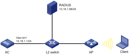
Configuration procedure
1. Configure the AC:
a. Configure 802.1X and the RADIUS scheme:
# Configure the AC to use EAP relay to authenticate 802.1X clients.
[AC] dot1x authentication-method eap
# Create a RADIUS scheme.
[AC] radius scheme imcc
# Specify the primary authentication server and the primary accounting server.
[AC-radius-imcc] primary authentication 10.18.1.88 1812
[AC-radius-imcc] primary accounting 10.18.1.88 1813
# Set the shared key for secure communication with the server to 12345678 in plain text.
[AC-radius-imcc] key authentication simple 12345678
[AC-radius-imcc] key accounting simple 12345678
# Exclude domain names in the usernames sent to the RADIUS server.
[AC-radius-imcc] user-name-format without-domain
[AC-radius-imcc] quit
b. Configure AAA methods for the ISP domain:
# Create an ISP domain named imc.
[AC] domain imc
# Configure the ISP domain to use the RADIUS scheme imcc for authentication, authorization, and accounting of LAN clients.
[AC-isp-imc] authentication lan-access radius-scheme imcc
[AC-isp-imc] authorization lan-access radius-scheme imcc
[AC-isp-imc] accounting lan-access radius-scheme imcc
[AC-isp-imc] quit
c. Configure a service template:
# Create a service template named wlas_imc_peap.
[AC] wlan service-template wlas_imc_peap
# Set the authentication mode to 802.1X.
[AC-wlan-st-wlas_imc_peap] client-security authentication-mode dot1x
# Specify the ISP domain imc for the service template.
[AC-wlan-st-wlas_imc_peap] dot1x domain imc
# Set the SSID to wlas_imc_peap.
[AC-wlan-st-wlas_imc_peap] ssid wlas_imc_peap
# Set the AKM mode to 802.1X.
[AC-wlan-st-wlas_imc_peap] akm mode dot1x
# Set the CCMP cipher suite.
[AC-wlan-st-wlas_imc_peap] cipher-suite ccmp
# Enable the RSN-IE in the beacon and probe responses.
[AC-wlan-st-wlas_imc_peap] security-ie rsn
# Enable the service template.
[AC-wlan-st-wlas_imc_peap] service-template enable
[AC-wlan-st-wlas_imc_peap] quit
d. Configure the manual AP ap1, and bind the service template to an AP radio:
# Create ap1, and specify the AP model and serial ID.
[AC] wlan ap ap1 model WA536-WW
[AC-wlan-ap-ap1] serial-id 219801A1NQB117012935
# Configure channel 149 as the working channel for radio 1 of the AP, and enable radio 1.
[AC-wlan-ap-ap1] radio 1
[AC-wlan-ap-ap1-radio-1] channel 149
[AC-wlan-ap-ap1-radio-1] radio enable
# Bind the service template wlas_imc_peap to radio 1.
[AC-wlan-ap-ap1-radio-1] service-template wlas_imc_peap
[AC-wlan-ap-ap1-radio-1] quit
[AC-wlan-ap-ap1] quit
2. Configure the RADIUS server:
In this example, the RADIUS server runs IMC PLAT 7.1 and IMC UAM 7.1, and the EAP-PEAP certificate has been installed.
# Add an access device:
a. Click the User tab.
b. From the navigation tree, select User Access Policy > Access Device Management > Access Device.
c. Click Add.
The Add Access Device page appears.
d. In the Access Configuration area, configure the following parameters, as shown in Figure 43:
- Enter 12345678 in the Shared Key and Confirm Shared Key fields.
- Use the default values for other parameters.
e. In the Device List area, click Select or Add Manually to add the device at 10.18.1.1 as an access device.
Figure 43 Adding an access device

f. Click OK.
# Add an access policy:
a. Click the User tab.
b. From the navigation tree, select User Access Policy > Access Policy.
c. Click Add.
d. On the Add Access Policy page, configure the following parameters, as shown in Figure 44:
- Enter dot1x in the Access Policy Name field.
- Select EAP for the Certificate Authentication field.
- Select EAP-PEAP Auth from the Certificate Type list, and select MS-CHAPV2 Auth from the Certificate Sub-Type list.
The certificate sub-type on the IMC server must be the same as the identity authentication method configured on the client.
Figure 44 Adding an access policy
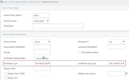
e. Click OK.
# Add an access service:
a. Click the User tab.
b. From the navigation tree, select User Access Policy > Access Service.
c. Click Add.
d. On the Add Access Service page, configure the following parameters, as shown in Figure 45:
- Enter dot1x in the Service Name field.
- Select dot1x from the Default Access Policy list.
Figure 45 Adding an access service
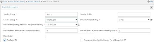
e. Click OK.
# Add an access user:
a. Click the User tab.
b. From the navigation tree, select Access User > All Access Users.
The access user list appears.
c. Click Add.
The Add Access User page appears.
d. In the Access Information area, configure the following parameters, as shown in Figure 46:
- Click Select or Add User to associate the user with IMC Platform user user.
- Enter user in the Account Name field.
- Enter dot1x in the Password and Confirm Password fields.
e. In the Access Service area, select dot1x from the list.
Figure 46 Adding an access user account
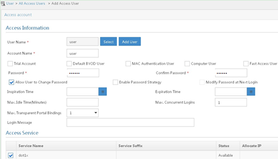
f. Click OK.
3. Configure the WLAN client:
The WLAN client has been installed with the EAP-PEAP certificate.
To configure the WLAN client, perform the following tasks (details not shown):
? Select PEAP for identity authentication.
? Disable the client from verifying the server certificate.
? Disable the client from automatically using the Windows login name and password.
Verifying the configuration
1. On the client, verify that you can use username user and password dot1x to access the network. (Details not shown.)
2. On the AC, perform the following tasks to verify that the user has passed authentication and come online:
# Display online 802.1X client information.
[AC] display dot1x connection
Total connections: 1
User MAC address : 0023-8933-2090
AP name : ap1
Radio ID : 1
SSID : wlas_imc_peap
BSSID : 000f-e201-0003
User name : user
Authentication domain : imc
Authentication method : EAP
Initial VLAN : 1
Authorization VLAN : N/A
Authorization ACL number : N/A
Authorization user profile : N/A
Termination action : Default
Session timeout period : 6001 s
Online from : 2014/04/18 09:25:18
Online duration : 0h 1m 1s
# Display WLAN client information.
[AC] display wlan client
Total number of clients : 1
MAC address Username AP name R IP address VLAN
0023-8933-2090 user ap1 1 10.18.1.100 1
RADIUS-based MAC authentication configuration example
Network requirements
As shown in Figure 47, configure the AC to use the RADIUS server to perform MAC authentication for the client.
Configuration procedure
Make sure the RADIUS server, AC, AP, and client can reach each other. (Details not shown.)
1. Configure the AC:
a. Configure the RADIUS scheme:
# Create a RADIUS scheme.
<AC> system-view
[AC] radius scheme imcc
# Specify the primary authentication server and the primary accounting server.
[AC-radius-imcc] primary authentication 10.18.1.88 1812
[AC-radius-imcc] primary accounting 10.18.1.88 1813
# Set the shared key for secure communication with the server to 12345678 in plain text.
[AC-radius-imcc] key authentication simple 12345678
[AC-radius-imcc] key accounting simple 12345678
# Exclude domain names in the usernames sent to the RADIUS server.
[AC-radius-imcc] user-name-format without-domain
[AC-radius-imcc] quit
b. Configure AAA methods for the ISP domain:
# Create an ISP domain named imc.
[AC] domain imc
# Configure the ISP domain to use the RADIUS scheme imcc for authentication, authorization, and accounting of LAN clients.
[AC-isp-imc] authentication lan-access radius-scheme imcc
[AC-isp-imc] authorization lan-access radius-scheme imcc
[AC-isp-imc] accounting lan-access radius-scheme imcc
[AC-isp-imc] quit
c. Specify the username 123 and the password aaa_maca in plain text for the account shared by MAC authentication clients.
[AC] mac-authentication user-name-format fixed account 123 password simple aaa_maca
d. Configure a service template:
# Create a service template named maca_imc.
[AC] wlan service-template maca_imc
# Set the SSID to maca_imc.
[AC-wlan-st-maca_imc] ssid maca_imc
# Set the authentication mode to MAC authentication.
[AC-wlan-st-maca_imc] client-security authentication-mode mac
# Specify the ISP domain imc for the service template.
[AC-wlan-st-maca_imc] mac-authentication domain imc
# Enable the service template.
[AC-wlan-st-maca_imc] service-template enable
[AC-wlan-st-maca_imc] quit
e. Configure the manual AP ap1, and bind the service template to an AP radio:
# Create a manual AP named ap1, and specify the AP model and serial ID.
[AC] wlan ap ap1 model WA536-WW
[AC-wlan-ap-ap1] serial-id 219801A1NQB117012935
# Configure channel 149 as the working channel for radio 1 of the AP, and enable radio 1.
[AC-wlan-ap-ap1] radio 1
[AC-wlan-ap-ap1-radio-1] channel 149
[AC-wlan-ap-ap1-radio-1] radio enable
# Bind the service template maca_imc to radio 1.
[AC-wlan-ap-ap1-radio-1] service-template maca_imc
[AC-wlan-ap-ap1-radio-1] quit
[AC-wlan-ap-ap1] quit
2. Configure the RADIUS server:
In this example, the RADIUS server runs IMC PLAT 7.1 and IMC UAM 7.1.
# Add an access device:
a. Click the User tab.
b. From the navigation tree, select User Access Policy > Access Device Management > Access Device.
c. Click Add.
The Add Access Device page appears.
d. In the Access Configuration area, configure the following parameters, as shown in Figure 48:
- Enter 12345678 in the Shared Key and Confirm Shared Key fields.
- Use the default values for other parameters.
e. In the Device List area, click Select or Add Manually to add the device at 10.18.1.1 as an access device.
Figure 48 Adding an access device
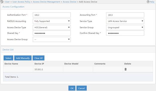
f. Click OK.
# Add an access policy:
a. Click the User tab.
b. From the navigation tree, select User Access Policy > Access Policy.
c. Click Add.
d. On the Add Access Policy page, configure the following parameters, as shown in Figure 49:
- Enter aaa_maca in the Access Policy Name field.
- Use the default values for other parameters.
Figure 49 Adding an access policy
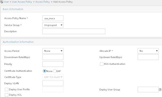
e. Click OK.
# Add an access service:
a. Click the User tab.
b. From the navigation tree, select User Access Policy > Access Service.
c. Click Add.
d. On the Add Access Service page, configure the following parameters, as shown in Figure 50:
- Enter aaa_maca in the Service Name field.
- Select aaa_maca from the Default Access Policy list.
Figure 50 Adding an access service
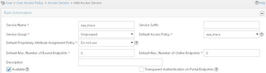
e. Click OK.
# Add an access user:
a. Click the User tab.
b. From the navigation tree, select Access User > All Access Users.
The access user list appears.
c. Click Add.
The Add Access User page appears.
d. In the Access Information area, configure the following parameters, as shown in Figure 51:
- Click Select or Add User to associate the user with IMC Platform user 123.
- Enter 123 in the Account Name field.
- Enter aaa_maca in the Password and Confirm Password fields.
e. In the Access Service area, select aaa_maca from the list.
Figure 51 Adding an access user account
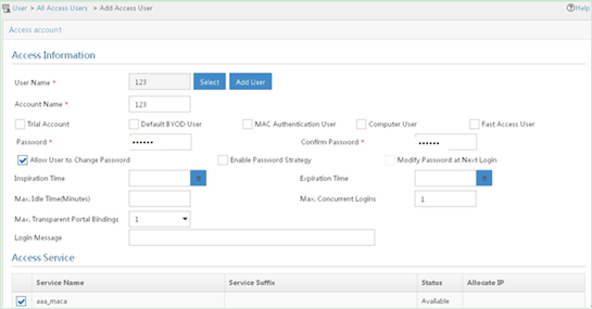
f. Click OK.
Verifying the configuration
1. On the client, verify that you can use username 123 and password aaa_maca to access the network. (Details not shown.)
2. On the AC, perform the following tasks to verify that the user has passed authentication and come online:
# Display online MAC authentication client information.
[AC] display mac-authentication connection
Total connections: 1
User MAC address : 0023-8933-2098
AP name : ap1
Radio ID : 1
SSID : maca_imc
BSSID : 000f-e201-0001
User name : 123
Authentication domain : imc
Initial VLAN : 1
Authorization VLAN : N/A
Authorization ACL number : N/A
Authorization user profile : N/A
Termination action : Default
Session timeout period : 6001 s
Online from : 2014/04/17 17:21:12
Online duration : 0h 0m 30s
# Display WLAN client information.
[AC] display wlan client
Total number of clients : 1
MAC address Username AP name R IP address VLAN
0023-8933-2098 123 ap1 1 10.18.1.100 1
Configuring WIPS
Overview
Wireless Intrusion Prevention System (WIPS) helps you monitor your WLAN, detect attacks and rogue devices, and take countermeasures. WIPS provides a complete solution for WLAN security.
WIPS contains the network management module, the AC, and sensors (APs enabled with WIPS). They provide the following functions:
· The sensors monitor the WLAN, collect channel information, and report the information to the AC for further analysis.
· The AC determines attacks and rogue devices, takes countermeasures, and triggers alarms.
· The network management module allows you to configure WIPS in the Web interface. It provides configuration management, report generation, and alarm management functions.
Attack detection
WIPS detects attacks by listening to 802.11 frames and triggers alarms to notify the administrator.
Flood attack detection
An AP might be facing a flood attack if it receives a large number of same-type frames within a short period of time. To prevent the AP from being overwhelmed, WIPS periodically examines incoming packet statistics, and alarms when it detects a suspicious flood attack. WIPS can detect the following flood attacks:
· Authentication request flood attack—Floods the association table of an AP by imitating many clients sending authentication requests to the AP.
· Probe request/association request/reassociation request flood attack—Floods the association table of an AP by imitating many clients sending probe requests/association requests/reassociation requests to the AP.
· EAPOL-start flood attack—Exhausts the AP's resources by imitating many clients sending EAPOL-start frames defined in IEEE 802.1X to the AP.
· Broadcast/unicast deauthentication flood attack—Spoofs deauthentication frames from the AP to the associated clients to disassociate the clients from the AP. This attack can rapidly terminate wireless services to multiple clients.
· Broadcast/unicast disassociation flood attack—Spoofs disassociation frames from the AP to the associated clients to disassociate the clients from the AP. This attack can rapidly terminate wireless services to multiple clients.
· RTS/CTS flood attack—Floods RTS/CTS frames to reserve the RF medium and force other wireless devices sharing the RF medium to hold back their transmissions. This attack takes advantage of vulnerabilities of the virtual carrier mechanism.
· Block Ack flood attack—Floods Block Ack frames to the AP to interrupt the operation of the Block Ack mechanism.
· Null data flood attack—Spoofs null data frames with power management bit 1 that are sent from a client to the AP. The AP determines that the client is in power save mode and buffers frames for the client. When the aging time of the buffered frames expires, the AP discards the frames. This interrupts the client's communication with the AP.
· Beacon flood attack—Floods beacon frames imitating a large number of fake APs to interrupt client association.
· EAPOL-logoff flood attack—The IEEE 802.1X standard defines the authentication protocol using Extensible Authentication Protocol over LANs (EAPOL). A client needs to send an EAPOL-logoff frame to terminate the session with an AP. The EAPOL-logoff frames are not authenticated, and an attacker can spoof EAPOL-logoff frames to disassociate a client.
· EAP-success/failure flood attack—In a WLAN using 802.1X authentication, an AP sends an EAP-success or EAP-failure frame to a client to inform authentication success or failure. An attacker can spoof the MAC address of an AP to send EAP-success or EAP-failure frames to a client to disrupt the authentication process.
Malformed packet detection
WIPS determines that a frame is malformed if the frame matches the criteria shown in Table 26, and then it triggers alarms and logs. WIPS can detect 16 kinds of malformed packets.
Table 26 Malformed frame match criteria
|
Detection type |
Applicable frames |
Match criteria |
|
Invalid IE length detection |
All management frames |
The IE length does not conform to the 802.11 protocol. The remaining length of the IE is not zero after the packet is resolved. |
|
Duplicate IE detection |
All management frames |
Duplicate IE. This type of detection is not applicable to vendor-defined IEs. |
|
Redundant IE detection |
All management frames |
The IE is not a necessary IE to the frame and is not a reserved IE. |
|
Invalid packet length detection |
All management frames |
The remaining length of the IE is not zero after the packet payload is resolved. |
|
Abnormal IBSS and ESS setting detection |
· Beacon frames · Probe response frames |
Both IBSS and ESS are set to 1. |
|
Malformed authentication request frame detection |
Authentication request frames |
· The authentication algorithm number does not conform to the 802.11 protocol and is larger than 3. · The authentication transaction sequence number is 1 and the status code is not 0. · The authentication transaction sequence number is larger than 4. |
|
Malformed association request frame detection |
Association request frames |
The frame length is 0. |
|
Malformed HT IE detection |
· Beacon frames · Probe responses · Association responses · Reassociation requests |
· The SM power save value for the HT capabilities IE is 2. · The secondary channel offset value for the HT operation IE is 2. |
|
Oversized duration detection |
· Unicast management frames · Unicast data frames · RTS, CTS, and ACK frames |
The packet duration value is larger than the specified threshold. |
|
Malformed probe response frame detection |
Probe response frames |
The frame is not a mesh frame and its SSID length is 0. |
|
Invalid deauthentication code detection |
Deauthentication frames |
The reason code is 0 or is in the range of 67 to 65535. |
|
Invalid disassociation code detection |
Disassociation frames |
The reason code is 0 or is in the range of 67 to 65535. |
|
Oversized SSID detection |
· Beacon frames · Probe requests · Probe responses · Association request frames |
The SSID length is larger than 32. |
|
FATA-Jack detection |
Authentication frames |
The value of the authentication algorithm number is 2. |
|
Invalid source address detection |
All management frames |
· The TO DS is 1, indicating that the frame is sent to the AP by a client. · The source MAC address of the frame is a multicast or broadcast address. |
|
Oversized EAPOL key detection |
EAPOL-Key frames |
The TO DS is 1 and the length of the key is larger than 0. |
Spoofing attack detection
In a spoofing attack, the attacker sends frames on behalf of another device to threaten the network. WIPS supports detecting the following spoofing attacks:
· Frame spoofing—A fake AP spoofs an authorized AP to send beacon or probe response frames to induce clients to associate with it.
· AP MAC address spoofing—A client spoofs an authorized AP to send deauthentication or disassociation frames to other clients. This can cause the clients to go offline and affect the correct operation of the WLAN.
· Client MAC address spoofing—A fake AP spoofs an authorized client to associate with an authorized AP.
Frame spoofing attack detection
WIPS calculates the startup time of an AP by using the frame receiving time and timestamp. If the calculated startup time of the AP is not the same as the startup time recorded in WIPS, WIPS determines that this is a spoofing attack.
AP MAC address spoofing attack detection
WIPS examines the MAC address of the sender. If the MAC address of the sender already exists in the AP MAC address table, WIPS determines that this is a spoofing attack.
Client MAC address spoofing attack detection
WIPS examines the MAC address of the sender. If the MAC address of the sender already exists in the client MAC address table, WIPS determines that this is a spoofing attack.
Weak IV detection
When the RC4 encryption algorithm, used by the WEP security protocol, uses an insecure IV, the WEP key is more likely to be cracked. An IV is a weak IV if its first byte is smaller than 16 (decimal) and its second byte is FF. WIPS prevents this kind of attack by detecting the IV in each WEP packet.
Omerta attack detection
Omerta is a DoS attack tool based on the 802.11 protocol. It sends disassociation frames with the reason code 0x01 to disassociate clients. Reason code 0x01 indicates an unknown disassociation reason. WIPS detects Omerta attacks by detecting the reason code of each disassociation frame.
Broadcast disassociation/deauthentication attack detection
An attacker spoofs a legitimate AP to send a broadcast disassociation or deauthentication frame to log off all clients associated with the AP.
Detection on clients with the 40 MHz bandwidth mode disabled
802.11n devices support both the 20 MHz and 40 MHz bandwidth modes. If the 40 MHz bandwidth mode is disabled on a client, other clients associated with the same AP as the client must also use the 20 MHz bandwidth. This affects network throughput and efficiency.
WIPS detects such clients by detecting probe request frames sent by the clients.
Power save attack detection
An attacker spoofs the MAC address of a client to send power save on frames to an AP. The AP caches the frames for the client. The attacked client cannot receive data frames because the AP determines that the client is still in power save mode. When the aging time of the cached frames expires, the AP discards the frames. WIPS detects power save attacks by determining the ratio of power save on frames to power save off frames.
Prohibited channel detection
After you configure a permitted channel list and enable prohibited channel detection, WIPS determines that channels that are not in the permitted channel list are prohibited channels.
Soft AP detection
A soft AP refers to a client that acts as an AP and provides wireless services. An attacker can access the internal network through a soft AP and then initiate further attacks. WIPS detects soft APs by detecting the interval at which a device switches its roles between client and AP. WIPS does not perform soft AP detection on unassociated clients.
Windows bridge detection
When a wireless client connected to a wired network establishes a Windows bridge through the wired NIC, the client can bridge an external AP with the internal network. This might bring security problems to the internal network. WIPS detects Windows bridges by analyzing data frames sent by associated clients.
Unencrypted device detection
An authorized AP or client that is transmitting unencrypted frames might bring security problems to the network. WIPS detects unencrypted devices by analyzing the frames sent the by authorized APs or clients.
Hotspot attack detection
An attacker sets up a rogue AP with the same SSID as a hotspot to lure the clients to associate with it. After the clients associate with the malicious AP, the attacker initiates further attacks to obtain client information.
You can configure a hotspot file to enable WIPS to detect hotspot attacks.
AP impersonation attack detection
In an AP impersonation attack, a malicious AP that has the same BSSID and ESSID as a legitimate AP lures the clients to associate with it. Then this impersonating AP initiates hotspot attacks or fools the detection system.
WIPS detects AP impersonation attacks by detecting the interval at which an AP sends beacon frames.
HT-greenfield AP detection
An AP operating in HT-greenfield mode might cause collisions, errors, and retransmissions because it cannot communicate with 802.11a/b/g devices. WIPS detects HT-greenfield APs by analyzing the beacon frames or probe response frames sent by APs.
Honeypot AP detection
In a honeypot AP attack, the attacker sets up a malicious AP to lure clients to associate with it. The SSID of the malicious AP is similar to the SSID of a legitimate AP. After a client associates with a honeypot AP, the honeypot AP initiates further attacks such as port scanning or fake authentication to obtain client information.
WIPS detects honeypot APs by detecting SSIDs of external APs. If the similarity between the SSID of an external AP and the SSID of a legitimate AP reaches the specified threshold, WIPS generates an alarm.
MITM attack detection
In an MITM attack, the attacker sets up a rogue AP and lures a client to associate with it. Then the rogue AP spoofs the MAC address of the client to associate with the authorized AP. When the client and the authorized AP communicate, the rogue AP captures packets from both the client and the authorized AP. The rogue AP might modify the frames and obtain the frame information. WIPS detects MITM attacks by detecting clients that are disassociated from an authorized AP and associated with a honeypot AP.
Wireless bridge detection
An attacker might intrude on the internal networks through a wireless bridge. When detecting a wireless bridge, WIPS generates an alarm. If the wireless bridge is in a mesh network, WIPS records the mesh link.
Association/reassociation DoS attack detection
An association/reassociation DoS attack floods the association table of an AP by imitating many clients sending association requests to the AP. When the number of entries in the table reaches the upper limit, the AP cannot process requests from legitimate clients.
AP flood attack detection
WIPS detects the number of APs in the WLAN and triggers an alarm for an AP flood attack when the number of APs exceeds the specified threshold.
Device entry attack detection
Attackers can send invalid packets to WIPS to increase processing costs. WIPS periodically examines the learned device entries to determine whether to rate limit device entry learning. If the number of AP or client entries learned within the specified interval exceeds the threshold, WIPS triggers an alarm and stops learning new entries.
User-defined attack detection based on signatures
WIPS provides user-defined attack detection based on signatures. A signature contains a packet identification method and actions to take on the matching packets. The sensor matches the detected packets against the signature, and takes actions defined in the signature if a packet matches the signature.
A signature can contain a maximum of six subsignatures, which can be defined based on the frame type, MAC address, serial ID, SSID length, SSID, and frame pattern. A packet matches a signature only when it matches all the subsignatures in the signature.
Device classification
AP classification
As shown in Table 27, WIPS classifies detected APs according to the predefined classification rules.
|
Category |
Description |
Classification rule |
|
Authorized AP |
An AP that is permitted in the WLAN. |
· Has been connected to the AC and not in the prohibited device list. · Configured as an authorized AP. · In the permitted device list. · Classified as an authorized AP by a user-defined AP classification rule. |
|
Rogue AP |
An AP that cannot be used in the WLAN. |
· In the prohibited device list. · Not in the OUI configuration file. · Configured as a rogue AP. · Classified as a rogue AP by a user-defined AP classification rule. If the wired port on an AP has been connected to the network and the AP is not connected to the AC, the AP might be a rogue AP. |
|
Misconfigured AP |
An AP that can be used in the WLAN but has incorrect configuration. |
· Configured as a misconfigured AP. · Classified as a misconfigured AP by a user-defined AP classification rule. |
|
External AP |
An AP that is in an adjacent WLAN. |
· Configured as an external AP. · Classified as an external AP by a user-defined AP classification rule. |
|
Ad hoc |
An AP operating in Ad hoc mode. WIPS detects Ad hoc APs by listening to beacon frames. |
N/A |
|
Mesh AP |
An AP in a WLAN mesh network. |
WIPS identifies mesh APs through beacon frames. |
|
Potential-authorized AP |
An AP that is possibly authorized. |
An AP is a potential-authorized AP if it meets all the following conditions: · Not in the permitted device list. · Not in the prohibited device list. · Not in the trusted SSID list. · Not in the trusted OUI list. · Has been connected to the AC. · Not manually classified. · Does not match any user-defined AP classification rules. |
|
Potential-rogue AP |
An AP that is possibly a rogue AP. |
Has incorrect wireless configuration and is not in any one of the following lists: · Permitted device list. · Prohibited device list. · Trusted OUI list. If the wired port on an AP has been connected to the network, the AP is a rogue AP. |
|
Potential-external AP |
An AP that is possibly an external AP. |
· Has incorrect wireless service configuration. · The wired port has not been connected to the network. · Not in any of the following lists: ? Permitted device list. ? Prohibited device list. ? Trusted OUI list. |
WIPS classifies detected APs by following the procedure shown in Figure 52.
Figure 52 AP classification flow
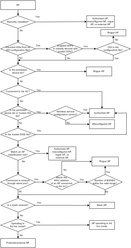
Client classification
As shown in Table 28, WIPS classifies detected clients according to the predefined classification rules.
Table 28 Client classification
|
Category |
Description |
Classification rule |
|
Authorized client |
A client that is permitted in the WLAN. |
· In the prohibited device list and associated with an authorized AP. · Has passed authentication and is associated with an authorized AP. |
|
Unauthorized client |
A client that cannot be used in the WLAN. |
· In the prohibited device list. · Associated with a rogue AP. · Not in the OUI configuration file. |
|
Misassociated client |
A client that is associated with an unauthorized AP. |
In the permitted device list but associated with an unauthorized AP. A misassociated client might bring security threats to the network. |
|
Uncategorized client |
A client whose category cannot be determined. |
N/A |
WIPS classifies detected clients by following the procedure shown in Figure 53.
Figure 53 Client classification flow
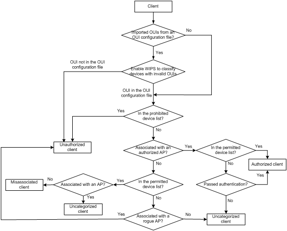
Countermeasures
Rogue devices are susceptible to attacks and might bring security problems to the WLAN. WIPS enables you to take countermeasures against rogue devices.
WIPS configuration task list
|
Tasks at a glance |
|
(Required.) Enabling WIPS |
|
(Optional.) Configuring wireless attack detection: · Configuring flood attack detection · Configuring malformed packet detection · Configuring device entry attack detection · Configuring detection on other attacks · Applying an attack detection policy · Configuring user-defined attack detection based on signatures |
|
(Optional.) Configuring device classification: |
|
(Optional.) Configuring countermeasures: |
|
(Optional.) Setting the wireless device information report interval |
|
(Optional.) Enabling fast learning of client association entries |
|
(Optional.) Enabling WIPS to detect unassociated clients |
|
(Optional.) Configuring WIPS detection filtering |
Enabling WIPS
You can divide a wireless network into multiple virtual security domains (VSDs) and apply different policies to these VSDs.
Before enabling WIPS for a radio of an AP, you must add the AP to a VSD.
Enabling WIPS in radio view
|
Step |
Command |
Remarks |
|
1. Enter system view. |
system-view |
N/A |
|
2. Enter AP view. |
wlan ap ap-name [ model model-name ] |
You must specify the model name when you create an AP. |
|
3. Add the AP to a VSD. |
wips virtual-security-domain vsd-name |
By default, an AP uses the configuration in AP group view. |
|
4. Enter radio view. |
radio radio-id |
N/A |
|
5. Enable WIPS. |
wips enable |
By default, an AP uses the configuration in AP group view. |
Enabling WIPS in AP group radio view
|
Step |
Command |
Remarks |
|
1. Enter system view. |
system-view |
N/A |
|
2. Enter AP group view. |
wlan ap-group group-name |
N/A |
|
3. Add the AP group to a VSD. |
wips virtual-security-domain vsd-name |
By default, an AP group is not in any VSD. |
|
4. Enter AP model view. |
ap-model ap-model |
N/A |
|
5. Enter radio view. |
radio radio-id |
N/A |
|
6. Enable WIPS. |
wips enable |
By default, WIPS is disabled. |
Configuring wireless attack detection
To configure wireless attack detection, you must first create an attack detection policy and enable detection of the specified attacks.
Configuring flood attack detection
|
Step |
Command |
Remarks |
|
1. Enter system view. |
system-view |
N/A |
|
2. Enter WIPS view. |
wips |
N/A |
|
3. Create an attack detection policy and enter its view. |
detect policy policy-name |
By default, no attack detection policy exists. |
|
4. Configure association request flood attack detection. |
flood association-request [ interval interval-value | quiet quiet-value | threshold threshold-value ] * |
By default, association request flood attack detection is disabled. |
|
5. Configure authentication request flood attack detection. |
flood authentication [ interval interval-value | quiet quiet-value | threshold threshold-value ] * |
By default, authentication request flood attack detection is disabled. |
|
6. Configure beacon flood attack detection. |
flood beacon [ interval interval-value | quiet quiet-value | threshold threshold-value ] * |
By default, beacon flood attack detection is disabled. |
|
7. Configure Block Ack flood attack detection. |
flood block-ack [ interval interval-value | quiet quiet-value | threshold threshold-value ] * |
By default, Block Ack flood attack detection is disabled. |
|
8. Configure RTS flood attack detection. |
flood rts [ interval interval-value | quiet quiet-value | threshold threshold-value ] * |
By default, RTS flood attack detection is disabled. |
|
9. Configure CTS flood attack detection. |
flood cts [ interval interval-value | quiet quiet-value | threshold threshold-value ] * |
By default, CTS flood attack detection is disabled. |
|
10. Configure deauthentication flood attack detection. |
flood deauthentication [ interval interval-value | quiet quiet-value | threshold threshold-value ] * |
By default, deauthentication flood attack detection is disabled. |
|
11. Configure disassociation flood attack detection. |
flood disassociation [ interval interval-value | quiet quiet-value | threshold threshold-value ] * |
By default, disassociation flood attack detection is disabled. |
|
12. Configure EAPOL-start flood attack detection. |
flood eapol-start [ interval interval-value | quiet quiet-value | threshold threshold-value ] * |
By default, EAPOL-start flood attack detection is disabled. |
|
13. Configure null data flood attack detection. |
flood null data [ interval interval-value | quiet quiet-value | threshold threshold-value ] * |
By default, null data flood attack detection is disabled. |
|
14. Configure probe request flood attack detection. |
flood probe-request [ interval interval-value | quiet quiet-value | threshold threshold-value ] * |
By default, probe request flood attack detection is disabled. |
|
15. Configure reassociation request flood attack detection. |
flood reassociation-request [ interval interval-value | quiet quiet-value | threshold threshold-value ] * |
By default, reassociation request flood attack detection is disabled. |
|
16. Configure EAPOL-logoff flood attack detection. |
flood eapol-logoff [ interval interval-value | quiet quiet-value | threshold threshold-value ]* |
By default, EAPOL-logoff flood attack detection is disabled. |
|
17. Configure EAP-failure flood attack detection. |
flood eap-failure [ interval interval-value | quiet quiet-value | threshold threshold-value ] * |
By default, EAP-failure flood attack detection is disabled. |
|
18. Configure EAP-success flood attack detection. |
flood eap-success [ interval interval-value | quiet quiet-value | threshold threshold-value ] * |
By default, EAP-success flood attack detection is disabled. |
Configuring malformed packet detection
|
Step |
Command |
Remarks |
|
1. Enter system view. |
system-view |
N/A |
|
2. Enter WIPS view. |
wips |
N/A |
|
3. Create an attack detection policy and enter its view. |
detect policy policy-name |
By default, no attack detection policy exists. |
|
4. Configure duplicated IE detection. |
malformed duplicated-ie [ quiet quiet-value ] |
By default, duplicated IE detection is disabled. |
|
5. Configure FATA-Jack detection. |
malformed fata-jack [ quiet quiet-value ] |
By default, FATA-Jack detection is disabled. |
|
6. Configure abnormal IBSS or ESS setting detection. |
malformed illegal-ibss-ess [ quiet quiet-value ] |
By default, abnormal IBSS or ESS setting detection is disabled. |
|
7. Configure invalid source address detection. |
malformed invalid-address-combination [ quiet quiet-value ] |
By default, invalid source address detection is disabled. |
|
8. Configure malformed association request frame detection. |
malformed invalid-assoc-req [ quiet quiet-value ] |
By default, malformed association request frame detection is disabled. |
|
9. Configure malformed authentication request frame detection. |
malformed invalid-auth [ quiet quiet-value ] |
By default, malformed authentication request frame detection is disabled. |
|
10. Configure invalid deauthentication code detection. |
malformed invalid-deauth-code [ quiet quiet-value ] |
By default, invalid deauthentication code detection is disabled. |
|
11. Configure invalid disassociation code detection. |
malformed invalid-disassoc-code [ quiet quiet-value ] |
By default, invalid disassociation code detection is disabled. |
|
12. Configure invalid IE length detection. |
malformed invalid-ie-length [ quiet quiet-value ] |
By default, invalid IE length detection is disabled. |
|
13. Configure malformed HT IE detection. |
malformed invalid-ht-ie [ quiet quiet-value ] |
By default, malformed HT IE detection is disabled. |
|
14. Configure invalid packet length detection. |
malformed invalid-pkt-length [ quiet quiet-value ] |
By default, invalid packet length detection is disabled. |
|
15. Configure oversized duration detection. |
malformed large-duration [ quiet quiet-value | threshold value ] |
By default, oversized duration detection is disabled. |
|
16. Configure malformed probe response frame detection. |
malformed null-probe-resp [ quiet quiet-value ] |
By default, malformed probe response frame detection is disabled. |
|
17. Configure oversized EAPOL key detection. |
malformed overflow-eapol-key [ quiet quiet-value ] |
By default, oversized EAPOL key detection is disabled. |
|
18. Configure oversized SSID detection. |
malformed overflow-ssid [ quiet quiet-value ] |
By default, oversized SSID detection is disabled. |
|
19. Configure redundant IE detection. |
malformed redundant-ie [ quiet quiet-value ] |
By default, redundant IE detection is disabled. |
Configuring device entry attack detection
|
Step |
Command |
Remarks |
|
1. Enter system view. |
system-view |
N/A |
|
2. Enter WIPS view. |
wips |
N/A |
|
3. Create an attack detection policy and enter its view. |
detect policy policy-name |
By default, no attack detection policy exists. |
|
4. Rate limit client entry learning. |
client-rate-limit [ interval interval-value | quiet quiet-value | threshold threshold-value ] * |
By default, the statistics collection interval is 60 seconds, the quiet time is 1200 seconds, and the client entry threshold is 512 for learned client entries. |
|
5. Set a client entry timer. |
client-timer inactive inactive-value aging aging-value |
By default, the inactive time is 300 seconds, and the aging time is 600 seconds. When a client neither receives nor sends packets within the inactive time, WIPS sets the client to inactive state. When a client neither receives nor sends frames within the aging time, WIPS deletes the entry. |
|
6. Rate limit AP entry learning. |
ap-rate-limit [ interval interval-value | quiet quiet-value | threshold threshold-value ] * |
By default, the statistics collection interval is 60 seconds, the quiet time is 1200 seconds, and the AP entry threshold is 64 for learned AP entries. |
|
7. Set an AP entry timer. |
ap-timer [ inactive inactive-value aging aging-value ] |
By default, the inactive time for APs is 300 seconds, and the aging time is 600 seconds. When an AP neither receives nor sends packets within the inactive time, WIPS sets the AP to inactive state. When an AP neither receives nor sends frames within the aging time, WIPS deletes the entry. |
Configuring detection on other attacks
|
Step |
Command |
Remarks |
|
|
1. Enter system view. |
system-view |
N/A |
|
|
2. Enter WIPS view. |
wips |
N/A |
|
|
3. Create an attack detection policy and enter its view. |
detect policy policy-name |
By default, no attack detection policy exists. |
|
|
4. Configure client MAC address spoofing attack detection. |
client-spoofing [ quiet quiet-value ] |
By default, client MAC address spoofing attack detection is disabled. |
|
|
5. Configure AP MAC address spoofing attack detection. |
ap-spoofing [ quiet quiet-value ] |
By default, AP MAC address spoofing attack detection is disabled. |
|
|
6. Configure weak IV detection. |
weak-iv [ quiet quiet-value ] |
By default, weak IV detection is disabled. |
|
|
7. Configure Omerta attack detection. |
omerta [ quiet quiet-value ] |
By default, Omerta attack detection is disabled. |
|
|
8. Configure broadcast disassociation attack detection. |
disassociation-broadcast [ interval interval-value | quiet quiet-value | threshold threshold-value ] * |
By default, broadcast disassociation attack detection is disabled. |
|
|
9. Configure broadcast deauthentication attack detection. |
deauthentication-broadcast [ interval interval-value | quiet quiet-value | threshold threshold-value ] * |
By default, broadcast deauthentication attack detection is disabled. |
|
|
10. Configure detection on clients with the 40 MHz bandwidth mode disabled. |
ht-40mhz-intolerance [ quiet quiet-value ] |
By default, detection on clients with the 40 MHz bandwidth mode disabled is disabled. |
|
|
11. Configure power saving attack detection. |
power-save [ interval interval-value | minoffpacket packet-value | onoffpercent percent-value | quiet quiet-value ] * |
By default, power saving attack detection is disabled. |
|
|
12. Configure the permitted channel list. |
permit-channel channel-id-list |
By default, no channel is added to the permitted channel list. |
|
|
13. Configure prohibited channel detection. |
prohibited-channel [ quiet quiet-value ] |
By default, prohibited channel detection is disabled. |
|
|
14. Configure Windows bridge detection. |
windows-bridge [ quiet quiet-value ] |
By default, Windows bridge detection is disabled. |
|
|
15. Configure unencrypted authorized AP detection. |
unencrypted-authorized-ap [ quiet quiet-value ] |
By default, unencrypted authorized AP detection is disabled. |
|
|
16. Configure unencrypted authorized client detection. |
unencrypted-trust-client [ quiet quiet-value ] |
By default, unencrypted authorized client detection is disabled. |
|
|
17. Configure soft AP detection. |
soft-ap [ convert-time time-value ] |
By default, soft AP detection is disabled. |
|
|
18. Configure AP impersonation attack detection. |
ap-impersonation [ quiet quiet-value ] |
By default, AP impersonation attack detection is disabled. |
|
|
19. Configure HT-greenfield AP detection. |
ht-greenfield [ quiet quiet-value ] |
By default, HT-greenfield AP detection is disabled. |
|
|
20. Configure association/reassociation DoS attack detection. |
association-table-overflow [ quiet quiet-value ] |
By default, association/reassociation DoS attack detection is disabled. |
|
|
21. Configure wireless bridge detection. |
wireless-bridge [ quiet quiet-value ] |
By default, wireless bridge detection is disabled. |
|
|
22. Configure AP flood attack detection. |
ap-flood [ apnum apnum-value | exceed exceed-value | quiet quiet-value ] * |
By default, AP flood attack detection is disabled. |
|
|
23. Configure honeypot AP detection. |
honeypot-ap [ similarity similarity-value | quiet quiet-value ] * |
By default, honeypot AP detection is disabled. |
|
|
24. Configure MITM attack detection. |
man-in-the-middle [ quiet quiet-value ] |
By default, MITM attack detection is disabled. |
|
|
25. Configure channel change detection. |
ap-channel-change [ quiet quiet-value ] |
By default, channel change detection is disabled. |
|
|
26. Return to WIPS view. |
quit |
N/A |
|
|
27. Import hotspot information from a configuration file. |
import hotspot file-name |
By default, no hotspot information is imported. |
|
|
28. Create an attack detection policy and enter its view. |
detect policy policy-name |
By default, no attack detection policy exists. |
|
|
29. Configure hotspot attack detection. |
hotspot-attack [ quiet quiet-value ] |
By default, hotspot attack detection is disabled. |
|
Applying an attack detection policy
|
Step |
Command |
Remarks |
|
1. Enter system view. |
system-view |
N/A |
|
2. Enter WIPS view. |
wips |
N/A |
|
3. Create a VSD and enter its view. |
virtual-security-domain vsd-name |
By default, no VSD exists. |
|
4. Apply an attack detection policy to the VSD. |
apply detect policy policy-name |
By default, no attack detection policy is applied to the VSD. An attack detection policy applied to a VSD takes effect on all radios in the VSD. |
Configuring user-defined attack detection based on signatures
Configuring a signature
WIPS matches detected packets against the configured signatures in ascending order of ID until a match is found.
You can configure one or multiple subsignatures for a signature. A packet matches a signature only when it matches all the subsignatures of the signature.
To configure a signature:
|
Step |
Command |
Remarks |
|
1. Enter system view. |
system-view |
N/A |
|
2. Enter WIPS view. |
wips |
N/A |
|
3. Create a signature and enter its view. |
signature rule rule-id |
By default, no signature is created. |
|
4. Configure a subsignature to match the frame type of a frame. |
frame-type { control | data | management [ frame-subtype { association-request | association-response | authentication | beacon | deauthentication | disassociation | probe-request } ] } |
By default, no subsignature is configured to match the frame type of a frame. |
|
5. Configure a subsignature to match the MAC address of a frame. |
mac-address { bssid | destination | source } mac-address |
By default, no subsignature is configured to match the MAC address of a frame. |
|
6. Configure a subsignature to match the sequence number of a frame. |
seq-number seq-value1 [ to seq-value2 ] |
By default, no subsignature is configured to match the sequence number of a frame. |
|
7. Configure a subsignature to match the SSID length of a frame. |
ssid-length length-value1 [ to length-value2 ] |
By default, no subsignature is configured to match the SSID length of a frame. |
|
8. Configure a subsignature to match the SSID of a frame. |
ssid [ case-sensitive ] [ not ] { equal | include } string |
By default, no subsignature is configured to match the SSID of a frame. |
|
9. Configure a subsignature to match the specified bits of a frame. |
pattern pattern-number offset offset-value mask hex-value value1 [ to value2 ] [ from-payload ] |
By default, no subsignature is configured to match the specified bits of a frame. |
Applying a signature
To apply a signature, bind the signature to a signature policy.
To apply a signature:
|
Step |
Command |
Remarks |
|
1. Enter system view. |
system-view |
N/A |
|
2. Enter WIPS view. |
wips |
N/A |
|
3. Create a signature policy and enter its view. |
signature policy policy-name |
By default, no signature policy is created. |
|
4. Bind the specified signature to the signature policy. |
apply signature rule rule-id |
By default, no signature is bound to a signature policy. |
|
5. Enable WIPS to detect packets that match the signature. |
detect signature [ interval interval-value | quiet quiet-value | threshold threshold-value ] * |
By default, WIPS detects packets that match a signature. The statistics collection interval is 60 seconds, the quiet interval is 600 seconds, and the alarm threshold is 50. |
Applying a signature policy
|
Step |
Command |
Remarks |
|
1. Enter system view. |
system-view |
N/A |
|
2. Enter WIPS view. |
wips |
N/A |
|
3. Create a VSD and enter its view. |
virtual-security-domain vsd-name |
By default, no VSD is created. |
|
4. Apply the specified signature policy to the VSD. |
apply signature policy policy-name |
By default, no signature policy is applied to a VSD. |
Configuring the alarm-ignored device list
For wireless devices in an alarm-ignored device list, WIPS only monitors them but does not trigger any alarms.
To configure the alarm-ignored device list:
|
Step |
Command |
Remarks |
|
1. Enter system view. |
system-view |
N/A |
|
2. Enter WIPS view. |
wips |
N/A |
|
3. Add the MAC address of a device to the alarm-ignored device list. |
ignorelist mac-address mac-address |
By default, no MAC address is added to the alarm-ignored device list. |
Configuring device classification
To configure wireless device classification, you must first create a classification policy and configure the classification of the specified devices.
Configuring a classification policy
You can enable WIPS to classify devices by using either of the following methods:
· Automatic classification—WIPS automatically classifies devices by adding the MAC addresses, OUIs, or SSIDs of the devices to the specified lists. WIPS also allows you to classify APs by using user-defined AP classification rules.
· Manual classification—You manually specify a category for a device. Manual classification is applicable only to APs.
If you configure both automatic classification and manual classification, manual classification takes effect.
Configuring automatic device classification
|
Step |
Command |
Remarks |
|
1. Enter system view. |
system-view |
N/A |
|
2. Enter WIPS view. |
wips |
N/A |
|
3. Import OUIs from an OUI configuration file. |
import oui file-name |
By default, no OUI is imported. |
|
4. Create a classification policy and enter its view. |
classification policy policy-name |
By default, no classification policy exists. |
|
5. Configure WIPS to classify devices with invalid OUIs as rogue devices. |
invalid-oui-classify illegal |
By default, WIPS does not classify devices with invalid OUIs as rogue devices. |
|
6. Add a MAC address to the permitted device list. |
trust mac-address mac-address |
By default, no MAC address exists in the permitted device list. |
|
7. Add an OUI to the trusted OUI list. |
trust oui oui |
By default, no OUI exists in the trusted OUI list. This command is applicable only to AP classification. |
|
8. Add an SSID to the trusted SSID list. |
trust ssid ssid-name |
By default, no SSID exists in the trusted SSID list. |
|
9. Add a MAC address to the static prohibited device list. |
block mac-address mac-address |
By default, no MAC address exists in to the static prohibited device list. |
|
10. Bind the specified AP classification rule to the classification policy. |
apply ap-classification rule rule-id { authorized-ap | { { external-ap | misconfigured-ap | rogue-ap } [ severity-level level ] } } |
By default, no AP classification rule is bound to a classification policy. |
Configuring an AP classification rule
|
Step |
Command |
Remarks |
|
1. Enter system view. |
system-view |
N/A |
|
2. Enter WIPS view. |
wips |
N/A |
|
3. Create an AP classification rule and enter its view. |
ap-classification rule rule-id |
By default, no AP classification rule is created. |
|
4. Configure the AP classification rule to match the RSSI of an AP. |
rssi value1 [ to value2 ] |
By default, an AP classification rule does not match the RSSI of an AP. |
|
5. Configure the AP classification rule to match the SSID of the wireless service for an AP. |
ssid [ case-sensitive ] [ not ] { equal | include } ssid-string |
By default, an AP classification rule does not match the SSID of the wireless service for an AP. |
|
6. Configure the AP classification rule to match the running time of an AP. |
up-duration value1 [ to value2 ] |
By default, an AP classification rule does not match the running time of an AP. |
|
7. Configure the AP classification rule to match the number of associated clients for an AP. |
client-online value1 [ to value2 ] |
By default, an AP classification rule does not match the number of associated clients for an AP. |
|
8. Configure the AP classification rule to match the number of sensors that detect an AP. |
discovered-ap value1 [ to value2 ] |
By default, an AP classification rule does not match the number of sensors that detect an AP. |
|
9. Configure the AP classification rule to match the security mode used by an AP. |
security { equal | include } { clear | wep | wpa | wpa2 } |
By default, an AP classification rule does not match the security mode used by an AP. |
|
10. Configure the AP classification rule to match the authentication mode used by an AP. |
authentication { equal | include } { 802.1x | none | other | psk } |
By default, an AP classification rule does not match the authentication mode used by an AP. |
|
11. Configure the AP classification rule to match the OUI information of an AP. |
oui oui-info |
By default, an AP classification rule does not match the OUI information of an AP. |
Configuring manual AP classification
|
Step |
Command |
Remarks |
|
1. Enter system view. |
system-view |
N/A |
|
2. Enter WIPS view. |
wips |
N/A |
|
3. Create a classification policy and enter its view. |
classification policy policy-name |
By default, no classification policy is created. |
|
4. Specify a category for the specified AP. |
manual-classify mac-address mac-address { authorized-ap | external-ap | misconfigured-ap | rogue-ap } |
By default, no category is specified for an AP. |
Applying a classification policy
|
Step |
Command |
Remarks |
|
1. Enter system view. |
system-view |
N/A |
|
2. Enter WIPS view. |
wips |
N/A |
|
3. Enter VSD view. |
virtual-security-domain vsd-name |
By default, no VSD exists. |
|
4. Apply a classification policy to the VSD. |
apply classification policy policy-name |
By default, no classification policy is applied on the VSD. A classification policy applied to a VSD takes effect on all radios in the VSD. |
Configuring countermeasures
To take countermeasures against rogue devices, you must first create a countermeasure policy and enable WIPS to take countermeasures against the specified devices.
Configuring a countermeasure policy
|
Step |
Command |
Remarks |
|
1. Enter system view. |
system-view |
N/A |
|
2. Enter WIPS view. |
wips |
N/A |
|
3. Create a countermeasure policy and enter its view. |
countermeasure policy policy-name |
By default, no countermeasure policy exists. |
|
4. Enable WIPS to take countermeasures against external APs. |
countermeasure external-ap |
By default, WIPS does not take countermeasures against external APs. |
|
5. Enable WIPS to take countermeasures against misconfigured APs. |
countermeasure misconfigured-ap |
By default, WIPS does not take countermeasures against misconfigured APs. |
|
6. Enable WIPS to take countermeasures against misassociated clients. |
countermeasure misassociation-client |
By default, WIPS does not take countermeasures against misassociated clients. |
|
7. Enable WIPS to take countermeasures against potential-external APs. |
countermeasure potential-external-ap |
By default, WIPS does not take countermeasures against potential-external APs. |
|
8. Enable WIPS to take countermeasures against potential-authorized APs. |
countermeasure potential-authorized-ap |
By default, WIPS does not take countermeasures against potential-authorized APs. |
|
9. Enable WIPS to take countermeasures against potential-rogue APs. |
countermeasure potential-rogue-ap |
By default, WIPS does not take countermeasures against potential-rogue APs. |
|
10. Enable WIPS to take countermeasures against rogue APs. |
countermeasure rogue-ap |
By default, WIPS does not take countermeasures against rogue APs. |
|
11. Enable WIPS to take countermeasures against unauthorized clients. |
countermeasure unauthorized-client |
By default, WIPS does not take countermeasures against unauthorized clients. |
|
12. Enable WIPS to take countermeasures against uncategorized APs. |
countermeasure uncategorized-ap |
By default, WIPS does not take countermeasures against uncategorized APs. |
|
13. Enable WIPS to take countermeasures against uncategorized clients. |
countermeasure uncategorized-client |
By default, WIPS does not take countermeasures against uncategorized clients. |
|
14. Enable WIPS to take countermeasures against the specified device. |
countermeasure mac-address mac-address |
By default, WIPS does not take countermeasures against devices. |
|
15. Enable WIPS to take countermeasures against Ad hoc devices. |
countermeasure adhoc |
By default, WIPS does not take countermeasures against Ad hoc devices. |
|
16. Enable WIPS to take countermeasures against devices that launch broadcast deauthentication attacks. |
countermeasure attack deauthentication-broadcast |
By default, WIPS does not take countermeasures against devices that launch broadcast deauthentication attacks. |
|
17. Enable WIPS to take countermeasures against devices that launch broadcast disassociation attacks. |
countermeasure attack disassociation-broadcast |
By default, WIPS does not take countermeasures against devices that launch broadcast disassociation attacks. |
|
18. Enable WIPS to take countermeasures against honeypot APs. |
countermeasure attack honeypot-ap |
By default, WIPS does not take countermeasures against honeypot APs. |
|
19. Enable WIPS to take countermeasures against devices that launch hotspot attacks. |
countermeasure attack hotspot-attack |
By default, WIPS does not take countermeasures against devices that launch hotspot attacks. |
|
20. Enable WIPS to take countermeasures against devices with the 40 MHz bandwidth mode disabled. |
countermeasure attack ht-40-mhz-intolerance |
By default, WIPS does not take countermeasures against devices with the 40 MHz bandwidth mode disabled. |
|
21. Enable WIPS to take countermeasures against devices that send malformed packets. |
countermeasure attack malformed-packet |
By default, WIPS does not take countermeasures against devices that send malformed packets. |
|
22. Enable WIPS to take countermeasures against devices that launch MITM attacks. |
countermeasure attack man-in-the-middle |
By default, WIPS does not take countermeasures against devices that launch MITM attacks. |
|
23. Enable WIPS to take countermeasures against devices that launch Omerta attacks. |
countermeasure attack omerta |
By default, WIPS does not take countermeasures against devices that launch Omerta attacks. |
|
24. Enable WIPS to take countermeasures against devices that launch power save attacks. |
countermeasure attack power-save |
By default, WIPS does not take countermeasures against devices that launch power save attacks. |
|
25. Enable WIPS to take countermeasures against soft APs. |
countermeasure attack soft-ap |
By default, WIPS does not take countermeasures against soft APs. |
|
26. Enable WIPS to take countermeasures against unencrypted authorized clients. |
countermeasure attack unencrypted-trust-client |
By default, WIPS does not take countermeasures against unencrypted authorized clients. |
|
27. Enable WIPS to take countermeasures against devices that use weak IVs. |
countermeasure attack weak-iv |
By default, WIPS does not take countermeasures against devices that use weak IVs. |
|
28. Enable WIPS to take countermeasures against devices that launch Windows bridge attacks. |
countermeasure attack windows-bridge |
By default, WIPS does not take countermeasures against devices that launch Windows bridge attacks. |
|
29. Enable WIPS to take countermeasures against all attackers. |
countermeasure attack all |
By default, WIPS does not take countermeasures against all attackers. |
|
30. Enable all sensors that detect an attacker to take countermeasures against the attacker. |
select sensor all |
By default, only the sensor that most recently detects an attacker takes countermeasures against the attacker. |
Applying a countermeasure policy
|
Step |
Command |
Remarks |
|
1. Enter system view. |
system-view |
N/A |
|
2. Enter WIPS view. |
wips |
N/A |
|
3. Create a VSD and enter its view. |
virtual-security-domain vsd-name |
By default, no VSD exists. |
|
4. Apply a countermeasure policy to the VSD. |
apply countermeasure policy policy-name |
By default, no countermeasure policy is applied on the VSD. A countermeasure policy applied to a VSD takes effect on all radios in the VSD. |
Setting the wireless device information report interval
To reduce the AC's processing pressure, perform this task to set an appropriate interval for APs to send wireless device information to the AC.
To set the wireless device information report interval:
|
Step |
Command |
Remarks |
|
1. Enter system view. |
system-view |
N/A |
|
2. Enter WIPS view. |
wips |
N/A |
|
3. Create an attack detection policy and enter attack detection policy view. |
detect policy policy-name |
N/A |
|
4. Set the interval at which APs report information about detected devices. |
report-interval interval |
By default, APs report information about detected devices every 30000 milliseconds. |
Enabling fast learning of client association entries
Client association entries are entries saved on the AC after a client associates with an AP.
If this feature is not enabled, the sensor can learn the client association entries only after a client is associated with an AP successfully. After this feature is enabled, the sensor can learn the client association entries during the association process.
If the sensor learned the client association entries during the association process, the sensor will update the entries every time it detects an association request or response between the AP and the client.
This feature improves the association efficiency but reduces the association accuracy. As a best practice, enable this feature only when fast attack detection and countermeasures are required in the network.
To enabling fast learning of client association entries:
|
Step |
Command |
Remarks |
|
1. Enter system view. |
system-view |
N/A |
|
2. Enter WIPS view. |
wips |
N/A |
|
3. Enter attack detection policy view. |
detect policy policy-name |
N/A |
|
4. Enable fast learning of client association entries. |
client-association fast-learn enable |
By default, fast learning of client association entries is disabled. |
Enabling WIPS to detect unassociated clients
As a best practice to save system resources, do not configure this feature when a large number of unassociated clients exist in the WLAN.
To enable WIPS to detect unassociated clients:
|
Step |
Command |
Remarks |
|
1. Enter system view. |
system-view |
N/A |
|
2. Enter WIPS view. |
wips |
N/A |
|
3. Create an attack detection policy and enter attack detection policy view. |
detect policy policy-name |
N/A |
|
4. Enable WIPS to detect unassociated clients. |
detect dissociate-client enable |
By default, WIPS does not detect unassociated clients. |
Configuring WIPS detection filtering
|
Step |
Command |
Remarks |
|
1. Enter system view. |
system-view |
N/A |
|
2. Enter WIPS view. |
wips |
N/A |
|
3. Create an attack detection policy and enter attack detection policy view. |
detect policy policy-name |
N/A |
|
4. Set the RSSI threshold for client or AP detection. |
rssi-threshold { ap ap-rssi-value | client client-rssi-value } |
By default, the RSSI thresholds for client and AP detection are not set. |
|
5. Set the RSSI difference threshold for wireless device detection. |
rssi-change-threshold threshold-value |
By default, the RSSI difference threshold is 20. |
Detecting clients with NAT configured
Perform this task to enable an AP to detect clients with NAT configured to prevent network sharing among clients.
Detecting clients with NAT configured in AP view
|
Step |
Command |
Remarks |
|
1. Enter system view. |
system-view |
N/A |
|
2. Create an AP and enter AP view. |
wlan ap ap-name [ model model-name ] |
You must specify the name and model when you create an AP. |
|
3. Enable the AP to detect clients with NAT configured. |
wlan nat-detect enable |
By default, an AP uses the configuration in AP group view. |
Detecting clients with NAT configured in AP group view
|
Step |
Command |
Remarks |
|
1. Enter system view. |
system-view |
N/A |
|
2. Create an AP group and enter AP group view. |
wlan ap-group group-name |
By default, a system-defined AP group exists. This AP group is named default-group and cannot be deleted. |
|
3. Enable APs in the AP group to detect clients with NAT configured. |
wlan nat-detect enable |
By default, APs do not detect clients with NAT configured. |
Displaying and maintaining WIPS
Execute display commands in any view and reset commands in user view.
|
Command |
|
|
Display information about all sensors. |
display wips sensor |
|
Display attack detection information collected by sensors. |
display wips statistics [ receive | virtual-security-domain vsd-name ] |
|
Display information about wireless devices detected in a VSD. |
display wips virtual-security-domain vsd-name device [ ap [ adhoc | authorized | external | misconfigured | potential-authorized | potential-external | potential-rogue | rogue ] | client [ [ dissociative-client ] [ authorized | misassociation | unauthorized | uncategorized ] ] | mac-address mac-address ] [ verbose ] |
|
Display information about countermeasures that WIPS has taken against rogue devices. |
display wips virtual-security-domain vsd-name countermeasure record |
|
Display information about detected NAT-configured clients. |
display wlan nat-detect [ mac-address mac-address ] |
|
Clear information received from all sensors. |
reset wips statistics |
|
Clear learned AP or client entries for a VSD. |
reset wips virtual-security-domain vsd-name { ap { all | mac-address mac-address} | client { all | mac-address mac-address } | all } |
|
Clear information about countermeasures that WIPS has taken against rogue devices. |
reset wips virtual-security-domain vsd-name countermeasure record |
|
Clear information about detected NAT-configured clients. |
reset wlan nat-detect |
WIPS configuration examples
Device classification and countermeasures configuration example
Network requirements
As shown in Figure 54, the sensor connects to the AC through the switch. AP 1 and AP 2 provide wireless services to clients through the SSID abc. Perform the following tasks:
· Enable WIPS for the sensor.
· Configure wireless device classification to add the MAC address 000f-1c35-12a5 to the static prohibited device list and the SSID abc is added to the trusted SSID list.
· Configure countermeasures to enable WIPS to take countermeasures against potential-external APs and unauthorized clients.
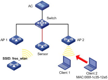
Configuration procedure
# Configure wireless services on the AC. (Details not shown.)
For more information about wireless service configuration, see "Configuring WLAN access."
# Create a VSD named vsd1.
<AC> system-view
[AC] wips
[AC-wips] virtual-security-domain vsd1
[AP-wips-vsd-vsd1] quit
[AC-wips] quit
# Create an AP named Sensor and enable WIPS for the AP.
[AC] wlan ap Sensor model WA536-WW
[AC-wlan-ap-Sensor] serial-id 219801A1NQB117012935
[AC-wlan-ap-Sensor] radio 1
[AC-wlan-ap-Sensor-radio-1] radio enable
[AC-wlan-ap-Sensor-radio-1] wips enable
[AC-wlan-ap-Sensor-radio-1] quit
#Add the AP Sensor to the VSD vsd1.
[AC-wlan-ap-Sensor] wips virtual-security-domain vsd1
[AC-wlan-ap-Sensor] quit
# Create a classification policy named class1, add the MAC address of Client 2 to the prohibited device list, and add SSID abc to the trusted SSID list.
[AC] wips
[AC-wips] classification policy class1
[AC-wips-cls-class1] block mac-address 000f-1c35-12a5
[AC-wips-cls-class1] trust ssid abc
[AC-wips-cls-class1] quit
# Apply the classification policy class1 to the VSD vsd1.
[AC-wips] virtual-security-domain vsd1
[AC-wips-vsd-vsd1] apply classification policy class1
[AC-wips-vsd-vsd1] quit
# Create a countermeasure policy named protect, and enable WIPS to take countermeasures against unauthorized clients and potential-external APs.
[AC-wips] countermeasure policy protect
[AC-wips-cms-protect] countermeasure unauthorized-client
[AC-wips-cms-protect] countermeasure potential-external-ap
[AC-wips-cms-protect] quit
# Apply the countermeasure policy protect to the VSD vsd1.
[AC-wips] virtual-security-domain vsd1
[AC-wips-vsd-vsd1] apply countermeasure policy protect
[AC-wips-vsd-vsd1] quit
[AC-wips] quit
Verifying the configuration
# Display wireless device classification information for the VSD vsd1.
[AC] display wips virtual-security-domain vsd1 device
Total 3 detected devices in virtual-security-domain vsd1
Class: Auth - authorization; Ext - extern; Mis - mistake;
Unauth - unauthorized; Uncate - uncategorized;
(A) - associate; (C) - config; (P) - potential
MAC address Type Class Duration Sensors Channel Status
00e0-fc00-5829 AP Auth 00h 10m 24s 1 149 Active
000f-e228-2528 AP Auth 00h 10m 04s 1 149 Active
000f-e223-1616 AP Ext(P) 00h 10m 46s 1 149 Active
000f-1c35-12a5 Client Unauth 00h 10m 02s 1 149 Active
000f-e201-0102 Client Auth 00h 10m 02s 1 149 Active
The output shows that the AP with the MAC address 000f-e223-1616 is classified as a potential-external AP and the client with the MAC address 000f-1c35-12a5 is classified as an unauthorized client.
# Display information about countermeasures that WIPS has taken against the devices.
[AC] display wips virtual-security-domain vsd1 countermeasure record
Total 2 times countermeasure, current 2 countermeasure record in virtual-security-domain vsd1
Reason: Attack; Ass - associated; Black - blacklist;
Class - classification; Manu - manual;
MAC address Type Reason Countermeasure AP Radio ID Time
000f-e223-1616 AP Class Sensor 1 2014-06-03/10:30:36
000f-1c35-12a5 Client Class Sensor 1 2014-06-03/09:13:26
The output shows that WIPS has taken countermeasures against the unauthorized client with the MAC address 000f-1c35-12a5 and the potential-external AP with the MAC address 000f-e223-1616.
Malformed packet and flood attack detection examples
Network requirements
As shown in Figure 55, configure the two APs that connect to the AC through the switch as sensors. Add Sensor 1 and Sensor 2 to the VSD VSD_1. Configure malformed packet detection and flood attack detection to enable WIPS to trigger an alarm when it detects beacon flood attacks or malformed packets with duplicated IE.
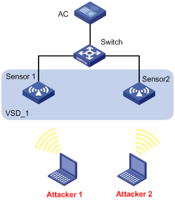
Configuration procedure
# Configure wireless services on the AC. (Details not shown.)
For more information about wireless service configuration, see "Configuring WLAN access."
# Create an AP named sensor1 and enable WIPS for the AP.
<AC> system-view
[AC] wlan ap sensor1 model WA536-WW
[AC-wlan-ap-sensor1] serial-id 219801A1NQB117012935
[AC-wlan-ap-sensor1] radio 1
[AC-wlan-ap-sensor1-radio-1] radio enable
[AC-wlan-ap-sensor1-radio-1] wips enable
[AC-wlan-ap-sensor1-radio-1] return
# Create an AP named sensor2 and enable WIPS for the AP.
<AC> system-view
[AC] wlan ap sensor2 model WA536-WW
[AC-wlan-ap-sensor2] serial-id 219801A1NQB117012952
[AC-wlan-ap-sensor2] radio 1
[AC-wlan-ap-sensor2-radio-1] radio enable
[AC-wlan-ap-sensor2-radio-1] wips enable
[AC-wlan-ap-sensor2-radio-1] quit
[AC-wlan-ap-sensor2] quit
# Create a VSD named VSD_1.
[AC] wips
[AC-wips] virtual-security-domain VSD_1
[AP-wips-vsd-VSD_1] quit
# Create an attack detection policy named dtc1.
[AC-wips] detect policy dtc1
# Enable detection on malformed packets with duplicated IE, and set the quiet time to 50 seconds.
[AC-wips-dtc-dtc1] malformed duplicated-ie quiet 50
# Enable beacon flood attack detection, and set the statistics interval, threshold, and quiet time to 100 seconds, 200, and 50 seconds, respectively.
[AC-wips-dtc-dtc1] flood beacon interval 100 quiet 50 threshold 200
[AC-wips-dtc-dtc1] quit
# Apply the attack detection policy dtc1 to the VSD VSD_1.
[AC-wips] virtual-security-domain VSD_1
[AC-wips-vsd-VSD_1] apply detect policy dtc1
[AC-wips-vsd-VSD_1] quit
[AC-wips] quit
# Add the AP sensor1 to the VSD VSD_1.
[AC] wlan ap sensor1
[AC-wlan-ap-sensor1] wips virtual-security-domain VSD_1
[AC-wlan-ap-sensor1] quit
# Add the AP sensor2 to the VSD VSD_1.
[AC] wlan ap sensor2
[AC-wlan-ap-sensor2] wips virtual-security-domain VSD_1
[AC-wlan-ap-sensor2] return
Verifying the configuration
# Display packet statistics when WIPS does not detect any attacks in the WLAN. The output shows that no malformed packet or flood attack message exists.
<AC> display wips statistics receive
Information from sensor 1
Information about attack statistics:
Detected association-request flood messages: 0
Detected authentication flood messages: 0
Detected beacon flood messages: 0
Detected block-ack flood messages: 0
Detected cts flood messages: 0
Detected deauthentication flood messages: 0
Detected disassociation flood messages: 0
Detected eapol-start flood messages: 0
Detected null-data flood messages: 0
Detected probe-request flood messages: 0
Detected reassociation-request flood messages: 0
Detected rts flood messages: 0
Detected duplicated-ie messages: 0
Detected fata-jack messages: 0
Detected illegal-ibss-ess messages: 0
Detected invalid-address-combination messages: 0
Detected invalid-assoc-req messages: 0
Detected invalid-auth messages: 0
Detected invalid-deauth-code messages: 0
Detected invalid-disassoc-code messages: 0
Detected invalid-ht-ie messages: 0
Detected invalid-ie-length messages: 0
Detected invalid-pkt-length messages: 0
Detected large-duration messages: 0
Detected null-probe-resp messages: 0
Detected overflow-eapol-key messages: 0
Detected overflow-ssid messages: 0
Detected redundant-ie messages: 0
Detected AP spoof AP messages: 0
Detected AP spoof client messages: 0
Detected AP spoof ad-hoc messages: 0
Detected ad-hoc spoof AP messages: 0
Detected client spoof AP messages: 0
Detected weak IV messages: 0
Detected excess AP messages: 0
Detected excess client messages: 0
Detected sig rule messages: 0
Information from sensor 2
Information about attack statistics:
Detected association-request flood messages: 0
Detected authentication flood messages: 0
Detected beacon flood messages: 0
Detected block-ack flood messages: 0
Detected cts flood messages: 0
Detected deauthentication flood messages: 0
Detected disassociation flood messages: 0
Detected eapol-start flood messages: 0
Detected null-data flood messages: 0
Detected probe-request flood messages: 0
Detected reassociation-request flood messages: 0
Detected rts flood messages: 0
Detected duplicated-ie messages: 0
Detected fata-jack messages: 0
Detected illegal-ibss-ess messages: 0
Detected invalid-address-combination messages: 0
Detected invalid-assoc-req messages: 0
Detected invalid-auth messages: 0
Detected invalid-deauth-code messages: 0
Detected invalid-disassoc-code messages: 0
Detected invalid-ht-ie messages: 0
Detected invalid-ie-length messages: 0
Detected invalid-pkt-length messages: 0
Detected large-duration messages: 0
Detected null-probe-resp messages: 0
Detected overflow-eapol-key messages: 0
Detected overflow-ssid messages: 0
Detected redundant-ie messages: 0
Detected AP spoof AP messages: 0
Detected AP spoof client messages: 0
Detected AP spoof ad-hoc messages: 0
Detected ad-hoc spoof AP messages: 0
Detected client spoof AP messages: 0
Detected weak IV messages: 0
Detected excess AP messages: 0
Detected excess client messages: 0
Detected sig rule messages: 0
# Display packet statistics when WIPS detects beacon flood attacks and malformed packets with duplicated IE. The output shows that the number of detected messages is 28 for malformed packets with duplicated IE and the number of detected messages is 18 for beacon flood attacks.
<AC> display wips statistics receive
Information from sensor 1
Information about attack statistics:
Detected association-request flood messages: 0
Detected authentication flood messages: 0
Detected beacon flood messages: 18
Detected block-ack flood messages: 0
Detected cts flood messages: 0
Detected deauthentication flood messages: 0
Detected disassociation flood messages: 0
Detected eapol-start flood messages: 0
Detected null-data flood messages: 0
Detected probe-request flood messages: 0
Detected reassociation-request flood messages: 0
Detected rts flood messages: 0
Detected duplicated-ie messages: 0
Detected fata-jack messages: 0
Detected illegal-ibss-ess messages: 0
Detected invalid-address-combination messages: 0
Detected invalid-assoc-req messages: 0
Detected invalid-auth messages: 0
Detected invalid-deauth-code messages: 0
Detected invalid-disassoc-code messages: 0
Detected invalid-ht-ie messages: 0
Detected invalid-ie-length messages: 0
Detected invalid-pkt-length messages: 0
Detected large-duration messages: 0
Detected null-probe-resp messages: 0
Detected overflow-eapol-key messages: 0
Detected overflow-ssid messages: 0
Detected redundant-ie messages: 0
Detected AP spoof AP messages: 0
Detected AP spoof client messages: 0
Detected AP spoof ad-hoc messages: 0
Detected ad-hoc spoof AP messages: 0
Detected client spoof AP messages: 0
Detected weak IV messages: 0
Detected excess AP messages: 0
Detected excess client messages: 0
Detected sig rule messages: 0
Information from sensor 2
Information about attack statistics:
Detected association-request flood messages: 0
Detected authentication flood messages: 0
Detected beacon flood messages: 0
Detected block-ack flood messages: 0
Detected cts flood messages: 0
Detected deauthentication flood messages: 0
Detected disassociation flood messages: 0
Detected eapol-start flood messages: 0
Detected null-data flood messages: 0
Detected probe-request flood messages: 0
Detected reassociation-request flood messages: 0
Detected rts flood messages: 0
Detected duplicated-ie messages: 28
Detected fata-jack messages: 0
Detected illegal-ibss-ess messages: 0
Detected invalid-address-combination messages: 0
Detected invalid-assoc-req messages: 0
Detected invalid-auth messages: 0
Detected invalid-deauth-code messages: 0
Detected invalid-disassoc-code messages: 0
Detected invalid-ht-ie messages: 0
Detected invalid-ie-length messages: 0
Detected invalid-pkt-length messages: 0
Detected large-duration messages: 0
Detected null-probe-resp messages: 0
Detected overflow-eapol-key messages: 0
Detected overflow-ssid messages: 0
Detected redundant-ie messages: 0
Detected AP spoof AP messages: 0
Detected AP spoof client messages: 0
Detected AP spoof ad-hoc messages: 0
Detected ad-hoc spoof AP messages: 0
Detected client spoof AP messages: 0
Detected weak IV messages: 0
Detected excess AP messages: 0
Detected excess client messages: 0
Detected sig rule messages: 0
Signature-based user-defined attack detection configuration example
Network requirements
As shown in Figure 56, AP 1 and AP 2 provide wireless services for clients through the SSID abc. Enable WIPS for the sensor, and configure a signature to enable WIPS to trigger an alarm when it detects beacon frames whose SSIDs are not abc.
Configuration procedure
# Configure wireless services on the AC. (Details not shown.)
For more information about wireless service configuration, see "Configuring WLAN access."
# Create an AP named sensor1 and enable WIPS for the AP.
<AC> system-view
[AC] wlan ap sensor1 model WA536-WW
[AC-wlan-ap-sensor1] serial-id 219801A1NQB117012935
[AC-wlan-ap-sensor1] radio 1
[AC-wlan-ap-sensor1-radio-1] radio enable
[AC-wlan-ap-sensor1-radio-1] wips enable
[AC-wlan-ap-sensor1-radio-1] quit
[AC-wlan-ap-sensor1 ] quit
# Create a VSD named vsd1.
[AC] wips
[AC-wips] virtual-security-domain vsd1
[AC-wips] quit
# Add the AP sensor1 to the VSD vsd1.
[AC] wlan ap sensor1
[AC-wlan-ap-sensor1] wips virtual-security-domain vsd1
[AC-wlan-ap-sensor1] quit
# Create signature 1, and configure a subsignature to match beacon frames and a subsignature to match frames whose SSIDs are not abc.
[AC] wips
[AC-wips] signature rule 1
[AC-wips-sig-rule-1] frame-type management frame-subtype beacon
[AC-wips-sig-rule-1] ssid not equal abc
[AC-wips-sig-rule-1] quit
# Create a signature policy named sig1, and bind signature 1 to the signature policy sig1.
[AC-wips] signature policy sig1
[AC-wips-sig-sig1] apply signature rule 1
# Enable WIPS to detect packets that match the signature, and set the statistics collection interval, quiet time, and alarm threshold to 5 seconds, 60 seconds, and 60, respectively.
[AC-wips-sig-sig1] detect signature interval 5 quiet 60 threshold 60
[AC-wips-sig-sig1] quit
# Apply the signature policy sig1 to the VSD vsd1.
[AC] wips
[AC-wips] virtual-security-domain vsd1
[AP-wips-vsd-vsd1] apply signature policy sig1
[AP-wips-vsd-vsd1] quit
Verifying the configuration
# Verify that the AC receives an alarm from the sensor when the sensor detects the wireless service with the SSID free_wlan.
WIPS/5/WIPS_SIGNATURE: -VSD=vsd1-RuleID=1; Signature rule matched.
# Display attack detection information collected from sensors. The output shows that the number of detected messages is 26 for packets that match the signature.
[AC] display wips statistics receive
Information from sensor
Information about attack statistics:
Detected association-request flood messages: 0
Detected authentication flood messages: 0
Detected beacon flood messages: 0
Detected block-ack flood messages: 0
Detected cts flood messages: 0
Detected deauthentication flood messages: 0
Detected disassociation flood messages: 0
Detected eapol-start flood messages: 0
Detected null-data flood messages: 0
Detected probe-request flood messages: 0
Detected reassociation-request flood messages: 0
Detected rts flood messages: 0
Detected duplicated-ie messages: 0
Detected fata-jack messages: 0
Detected illegal-ibss-ess messages: 0
Detected invalid-address-combination messages: 0
Detected invalid-assoc-req messages: 0
Detected invalid-auth messages: 0
Detected invalid-deauth-code messages: 0
Detected invalid-disassoc-code messages: 0
Detected invalid-ht-ie messages: 0
Detected invalid-ie-length messages: 0
Detected invalid-pkt-length messages: 0
Detected large-duration messages: 0
Detected null-probe-resp messages: 0
Detected overflow-eapol-key messages: 0
Detected overflow-ssid messages: 0
Detected redundant-ie messages: 0
Detected AP spoof AP messages: 0
Detected AP spoof client messages: 0
Detected AP spoof ad-hoc messages: 0
Detected ad-hoc spoof AP messages: 0
Detected client spoof AP messages: 0
Detected weak IV messages: 0
Detected excess AP messages: 0
Detected excess client messages: 0
Detected sig rule messages: 26
Configuring WLAN QoS
This chapter describes how to configure WLAN QoS.
Overview
An 802.11 network provides contention-based wireless access. To provide applications with QoS services, IEEE developed 802.11e for 802.11-based WLANs.
While IEEE 802.11e was being standardized, Wi-Fi Alliance defined the Wi-Fi Multimedia (WMM) standard to allow QoS provision devices of different vendors to interoperate. WMM enables a WLAN to provide QoS services, so that audio and video applications can have better performance in WLANs.
WMM protocol
The Distributed Coordination Function (DCF) in 802.11 requires APs and clients to use the carrier sense multiple access with collision avoidance (CSMA/CA) access mechanism. APs or clients listen to the channel before they hold the channel for data transmission. When the specified idle duration of the channel times out, APs or clients randomly select a backoff slot within the contention window to perform backoff. The device that finishes backoff first gets the channel. With 802.11, all devices have the same idle duration and contention window. Therefore, they are equal when contending for a channel.
To provide QoS services, WMM divides data traffic into four ACs that have different priorities. Traffic in an AC with a high priority has a better chance to use the channel.
Terminology
· Enhanced distributed channel access—EDCA is a channel contention mechanism defined by WMM to preferentially transmit packets with high priority and allocate more bandwidth to such packets.
· Access category—WMM defines four ACs: AC-VO for voice traffic, AC-VI for video traffic, AC-BE for best effort traffic, and AC-BK for background traffic. The priorities of the four ACs are in descending order.
· Connect Admission Control—CAC limits the number of clients that can use high-priority ACs (AC-VO and AC-VI) to make sure there is enough bandwidth for these clients.
· Unscheduled automatic power save delivery—U-APSD is a power saving method defined by WMM to save client power.
EDCA parameters
· Arbitration inter-frame spacing number—In 802.11-based WLAN, each client has the same idle duration (DIFS), but WMM defines an idle duration for each AC. The idle duration increases as the AIFSN increases.
· Exponent form of CWmin/Exponent form of CWmax—ECWmin/ECWmax determines the backoff slots, which increase as the two values increase.
· Transmission opportunity limit—TXOP limit specifies the maximum time that a client can hold the channel after a successful contention. A larger value represents a longer time. If the value is 0, a client can send only one packet each time it holds the channel.
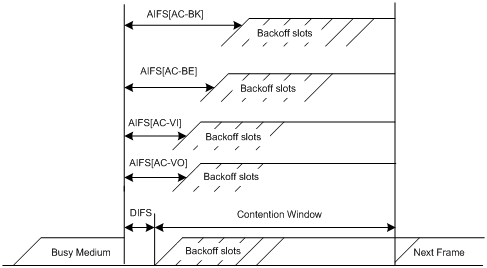
CAC admission policies
CAC requires a client to obtain permission from an AP before it can use a high-priority AC for transmission. This guarantees bandwidth for the clients that have gained access. CAC controls real time traffic (AC-VO and AC-VI traffic) but not common data traffic (AC-BE and AC-BK traffic).
If a client wants to use a high-priority AC (AC-VO or AC-VI), it must send a request to the AP. The AP returns a positive or negative response based on either of the following admission control policies:
· Channel usage-based admission policy—The AP calculates the total time that the existing high-priority AC queues occupy the channel per unit time, and then calculates the time that the requesting traffic will occupy the channel per unit time. If the sum of the two values is smaller than or equal to the maximum hold time of the channel, the client can use the requested AC queue. If it is not, the request is rejected.
· Client-based admission policy—If the number of clients using high-priority AC queues is smaller than the maximum number of high-priority AC clients, the request is accepted. If it is not, the request is rejected. During calculation, a client is counted as one client if it is using both the AC-VO and AC-VI queues.
If the request is rejected, the AP assigns AC-BE to clients.
U-APSD power-save mechanism
U-APSD enables clients in sleep mode to wake up and receive the specified number of packets only after receiving a trigger packet. U-APSD improves the 802.11 APSD power saving mechanism.
U-APSD is automatically enabled after you enable WMM.
ACK policy
WMM defines the following ACK policies:
· Normal ACK—The recipient acknowledges each received unicast packet.
· No ACK—The recipient does not acknowledge received packets during wireless packet exchange. This policy improves the transmission efficiency in an environment where communication quality is strong and interference is weak. If communication quality deteriorates, this policy might increase the packet loss rate. For A-MPDU packets sent by 802.11n clients, the No ACK policy does not take effect.
SVP
SpectraLink Voice Priority (SVP) is developed by SpectraLink to provide QoS services for voice traffic.
Bandwidth guaranteeing
This feature provides the following functions:
· Ensures that traffic from all BSSs can pass through freely when the network is not congested.
· Ensures that each BSS can get the guaranteed bandwidth when the network is congested.
This feature improves bandwidth efficiency and maintains fair use of bandwidth among WLAN services. For example, you assign SSID1, SSID2, and SSID3 25%, 25%, and 50% of the total bandwidth. When the network is not congested, SSID1 can use all idle bandwidth in addition to its guaranteed bandwidth. When the network is congested, SSID1 is guaranteed with 25% of the bandwidth.
This feature applies only to AP-to-client traffic.
Client rate limiting
This feature prevents aggressive use of bandwidth by one client and ensures fair use of bandwidth among clients associated with the same AP.
You can configure either of the following modes for client rate limiting:
· Dynamic mode—Sets the total bandwidth shared by all clients. The rate limit for each client is the total rate divided by the number of online clients. For example, if the total rate is 10 Mbps and five clients are online, the rate limit for each client is 2 Mbps.
· Static mode—Sets the bandwidth that can be used by each client. When the rate limit multiplied by the number of associated clients exceeds the available bandwidth provided by the AP, the clients might not get the set bandwidth.
Protocols and standards
· 802.11e-2005, Amendment 8: Medium Access Control (MAC) Quality of Service Enhancements, IEEE Computer Society, 2005
· Wi-Fi, WMM Specification version 1.1, Wi-Fi Alliance, 2005
Configuration restrictions and guidelines
The priorities for the configuration in AP view, AP group view, and global configuration view are in descending order.
Configuring WMM
Enabling WMM
The 802.11n protocol requires all 802.11n clients to support WLAN QoS. For 802.11n clients to communicate with the associated AP, enable WMM when the radio operates in 802.11an or 802.11gn mode.
Enabling WMM for an AP
|
Step |
Command |
Remarks |
|
1. Enter system view. |
system-view |
N/A |
|
2. Enter AP view. |
wlan ap ap-name [ model model-name ] |
N/A |
|
3. Enter radio view. |
radio radio-id |
N/A |
|
4. Enable WMM. |
wmm enable |
By default, an AP uses the configuration in AP group view. |
Enabling WMM for an AP group
|
Step |
Command |
Remarks |
|
1. Enter system view. |
system-view |
N/A |
|
2. Enter AP group view. |
N/A |
|
|
3. Enter AP model view. |
N/A |
|
|
4. Enter radio view. |
radio radio-id |
N/A |
|
5. Enable WMM. |
wmm enable |
By default, WMM is enabled. |
Setting EDCA parameters
Setting EDCA parameters for an AP
|
Step |
Command |
Remarks |
|
1. Enter system view. |
system-view |
N/A |
|
2. Enter AP view. |
wlan ap ap-name [ model model-name ] |
N/A |
|
3. Enter radio view. |
radio radio-id |
N/A |
|
4. Set EDCA parameters. |
edca radio { ac-be | ac-bk | ac-vi | ac-vo } { ack-policy { noack | normalack } | aifsn aifsn-value | ecw ecwmin ecwmin-value ecwmax ecwmax-value | txoplimit txoplimit-value } * |
By default, an AP uses the configuration in AP group view. |
Setting EDCA parameters for an AP group
|
Step |
Command |
Remarks |
|
1. Enter system view. |
system-view |
N/A |
|
2. Enter AP group view. |
N/A |
|
|
3. Enter AP model view. |
N/A |
|
|
4. Enter radio view. |
radio radio-id |
N/A |
|
5. Set EDCA parameters. |
edca radio { ac-be | ac-bk | ac-vi | ac-vo } { ack-policy { noack | normalack } | aifsn aifsn-value | ecw ecwmin ecwmin-value ecwmax ecwmax-value | txoplimit txoplimit-value } * |
The default values for EDCA parameters are shown in Table 29. |
Table 29 Default EDCA parameter values
|
AC |
AIFSN |
ECWmin |
ECWmax |
TXOP Limit |
|
AC-BK |
7 |
4 |
10 |
0 |
|
AC-BE |
3 |
4 |
6 |
0 |
|
AC-VI |
1 |
3 |
4 |
94 |
|
AC-VO |
1 |
2 |
3 |
47 |
Setting EDCA parameters for clients (AC-BE or AC-BK)
Setting EDCA parameters for clients for an AP
|
Step |
Command |
Remarks |
|
1. Enter system view. |
system-view |
N/A |
|
2. Enter AP view. |
wlan ap ap-name [ model model-name ] |
N/A |
|
3. Enter radio view. |
radio radio-id |
N/A |
|
4. Set EDCA parameters of AC-BE or AC-BK queues for clients. |
edca client { ac-be | ac-bk } { aifsn aifsn-value | ecw ecwmin ecwmin-value ecwmax ecwmax-value | txoplimit txoplimit-value } * |
By default, an AP uses the configuration in AP group view. |
Setting EDCA parameters for clients for an AP group
|
Step |
Command |
Remarks |
|
1. Enter system view. |
system-view |
N/A |
|
2. Enter AP group view. |
N/A |
|
|
3. Enter AP model view. |
N/A |
|
|
4. Enter radio view. |
radio radio-id |
N/A |
|
5. Set EDCA parameters of AC-BE or AC-BK queues for clients. |
edca client { ac-be | ac-bk } { aifsn aifsn-value | ecw ecwmin ecwmin-value ecwmax ecwmax-value | txoplimit txoplimit-value } * |
The default values are shown in Table 30. |
Table 30 Default EDCA parameter values of AC-BE or AC-BK queues for clients
|
AC |
AIFSN |
ECWmin |
ECWmax |
TXOP Limit |
|
AC-BK |
7 |
4 |
10 |
0 |
|
AC-BE |
3 |
4 |
10 |
0 |
Setting EDCA parameters for clients (AC-VI or AC-VO)
Setting EDCA parameters for clients for an AP
|
Step |
Command |
Remarks |
|
1. Enter system view. |
system-view |
N/A |
|
2. Enter AP view. |
wlan ap ap-name [ model model-name ] |
N/A |
|
3. Enter radio view. |
radio radio-id |
N/A |
|
4. Set EDCA parameters of AC-VI or AC-VO queues for clients. |
edca client { ac-vi | ac-vo } { aifsn aifsn-value | cac { disable | enable } | ecw ecwmin ecwmin-value ecwmax ecwmax-value | txoplimit txoplimit-value } * |
By default, an AP uses the configuration in AP group view. |
|
5. (Optional.) Configure the CAC policy. |
cac policy { channelutilization [ channelutilization-value ] | client [ client-number ] } |
By default, an AP uses the configuration in AP group view. |
Setting EDCA parameters for clients for an AP group
|
Step |
Command |
Remarks |
|
1. Enter system view. |
system-view |
N/A |
|
2. Enter AP group view. |
N/A |
|
|
3. Enter AP model view. |
N/A |
|
|
4. Enter radio view. |
radio radio-id |
N/A |
|
5. Set EDCA parameters of AC-VI or AC-VO queues for clients. |
edca client { ac-vi | ac-vo } { aifsn aifsn-value | cac { disable | enable } | ecw ecwmin ecwmin-value ecwmax ecwmax-value | txoplimit txoplimit-value } * |
The default values are shown in Table 31. |
|
6. (Optional.) Configure the CAC policy. |
cac policy { channelutilization [ channelutilization-value ] | client [ client-number ] } |
By default, the client-based admission policy is used, and the maximum number of admitted clients is 20. |
Table 31 Default EDCA parameter values of AC-VI or AC-VO queues for clients
|
AC |
AIFSN |
ECWmin |
ECWmax |
TXOP Limit |
|
AC-VI |
2 |
3 |
4 |
94 |
|
AC-VO |
2 |
2 |
3 |
47 |
Configuring a port to trust packet priority for priority mapping
This feature takes effect only on uplink packets.
To configure a port to trust packet priority for priority mapping:
|
Step |
Command |
Remarks |
|
1. Enter system view. |
system-view |
N/A |
|
2. Enter service template view. |
N/A |
|
|
3. Configure the trusted packet priority type. |
By default, the port priority is trusted. |
|
|
4. Set the port priority. |
By default, the port priority is 0. |
Configuring SVP mapping
SVP mapping takes effect only on non-WMM clients.
This feature assigns packets that have the protocol ID 119 in the IP header to the AC-VI or AC-VO queue to provide SVP packets with the specified priority. SVP does not require random backoff for SVP packets. Therefore, you can set both ECWmin and ECWmax to 0 when there are only SVP packets in the AC-VI or AC-VO queue.
When SVP mapping is disabled, SVP packets are assigned to the AC-BE queue.
Configuring SVP mapping for an AP
|
Step |
Command |
Remarks |
|
1. Enter system view. |
system-view |
N/A |
|
2. Enter AP view. |
wlan ap ap-name [ model model-name ] |
N/A |
|
3. Enter radio view. |
radio radio-id |
N/A |
|
4. Configure SVP mapping. |
svp map-ac { ac-vi | ac-vo | disable } |
By default, an AP uses the configuration in AP group view. |
Configuring SVP mapping for an AP group
|
Step |
Command |
Remarks |
|
1. Enter system view. |
system-view |
N/A |
|
2. Enter AP group view. |
N/A |
|
|
3. Enter AP model view. |
N/A |
|
|
4. Enter radio view. |
radio radio-id |
N/A |
|
5. Configure SVP mapping. |
svp map-ac { ac-vi | ac-vo | disable } |
By default, SVP mapping is disabled. |
Configuring bandwidth guaranteeing
Configuring bandwidth guaranteeing for an AP
|
Step |
Command |
Remarks |
|
1. Enter system view. |
system-view |
N/A |
|
2. Set the maximum bandwidth for the specified radio type. |
wlan max-bandwidth { dot11a | dot11ac | dot11an | dot11b | dot11g | dot11gac | dot11gn } bandwidth |
The following default settings apply: · 30000 Kbps for dot11a and dot11g. · 250000 Kbps for dot11an, dot11gn, and dot11gac. · 500000 Kbps for dot11ac. · 7000 Kbps for dot11b. |
|
3. Enter AP view. |
wlan ap ap-name [ model model-name ] |
N/A |
|
4. Enter radio view. |
radio radio-id |
N/A |
|
5. Configure bandwidth guaranteeing. |
bandwidth-guarantee { disable | enable } |
The following default settings apply: · If the service template setting in AP group view is used, an AP uses the configuration in AP group view. · If a service template is manually bound to a radio, bandwidth guaranteeing is disabled. |
|
6. Set a guaranteed bandwidth percentage for the specified service template. |
bandwidth-guarantee service-template service-template-name percent percent |
The following default settings apply: · If the service template setting in AP group view is used, an AP uses the configuration in AP group view. · If a service template is manually bound to a radio, no guaranteed bandwidth percentage is set for the service template. |
Configuring bandwidth guaranteeing for an AP group
|
Step |
Command |
Remarks |
|
1. Enter system view. |
system-view |
N/A |
|
2. Set the maximum bandwidth for the specified radio type. |
wlan max-bandwidth { dot11a | dot11ac | dot11an | dot11b | dot11g | dot11gac | dot11gn } bandwidth |
The following default settings apply: · 30000 Kbps for dot11a and dot11g. · 250000 Kbps for dot11an, dot11gn, and dot11gac. · 500000 Kbps for dot11ac. · 7000 Kbps for dot11b. |
|
3. Enter AP group view. |
wlan ap-group group-name |
N/A |
|
4. Enter AP model view. |
ap-model ap-model |
N/A |
|
5. Enter radio view. |
radio radio-id |
N/A |
|
6. Configure bandwidth guaranteeing. |
bandwidth-guarantee { disable | enable } |
By default, bandwidth guaranteeing is disabled. |
|
7. Set a guaranteed bandwidth percentage for the specified service template. |
bandwidth-guarantee service-template service-template-name percent percent |
By default, no guaranteed bandwidth percentage is set for a service template. |
Configuring client rate limiting
By rate limit method, you can configure service-template-based, radio-based, or client-type-based client rate limiting. By rate limit mode, you can configure the dynamic or static mode for client rate limiting.
If more than one method and mode are configured, all settings take effect. The rate for a client will be limited to the minimum value among all the client rate-limiting settings.
Configuring service-template-based client rate limiting
This task takes effects on all clients associated with the same service template.
To configure service-template-based client rate limiting:
|
Step |
Command |
Remarks |
|
1. Enter system view. |
system-view |
N/A |
|
2. Enter service template view. |
wlan service-template service-template-name |
N/A |
|
3. Enable service-template-based client rate limiting. |
client-rate-limit enable |
By default, service-template-based client rate limiting is disabled. |
|
4. Configure service-template-based client rate limiting. |
client-rate-limit { inbound | outbound } mode { dynamic | static } cir cir |
By default, service-template-based client rate limiting is not configured. |
Configuring radio-based client rate limiting
This task takes effects on all clients associated with the same radio.
Configuring radio-based client rate limiting for an AP
|
Step |
Command |
Remarks |
|
1. Enter system view. |
system-view |
N/A |
|
2. Enter AP view. |
wlan ap ap-name [ model model-name ] |
N/A |
|
3. Enter radio view. |
radio radio-id |
N/A |
|
4. Enable or disable radio-based client rate limiting. |
client-rate-limit { disable | enable } |
By default, an AP uses the configuration in AP group view. |
|
5. Configure radio-based client rate limiting. |
client-rate-limit { inbound | outbound } mode { dynamic | static } cir cir |
By default, an AP uses the configuration in AP group view. |
Configuring radio-based client rate limiting for an AP group
|
Step |
Command |
Remarks |
|
1. Enter system view. |
system-view |
N/A |
|
2. Enter AP group view. |
wlan ap-group group-name |
N/A |
|
3. Enter AP model view. |
ap-model ap-model |
N/A |
|
4. Enter radio view. |
radio radio-id |
N/A |
|
5. Enable or disable radio-based client rate limiting. |
client-rate-limit { disable | enable } |
By default, radio-based client rate limiting is disabled. |
|
6. Configure radio-based client rate limiting. |
client-rate-limit { inbound | outbound } mode { dynamic | static } cir cir |
By default, radio-based client rate limiting is not configured. |
Configuring client-type-based client rate limiting
This task takes effects on all clients of the specified protocol.
To configure client-type-based client rate limiting:
|
Step |
Command |
Remarks |
|
1. Enter system view. |
system-view |
N/A |
|
2. Configure client-type-based client rate limiting. |
wlan client-rate-limit { dot11a | dot11ac | dot11an | dot11b | dot11g | dot11gac | dot11gn } { inbound | outbound } cir cir [ cbs cbs ] |
By default, client-type-based client rate limiting is not configured. |
Displaying and maintaining WMM
Execute display commands in any view and reset commands in user view.
|
Task |
Command |
|
Display WMM statistics for radios. |
|
|
Display WMM statistics for clients. |
display wlan wmm client { all | ap ap-name | mac-address mac-address } |
|
Clear WMM statistics for radios. |
reset wlan wmm radio { all | ap ap-name } |
|
Clear WMM statistics for clients. |
reset wlan wmm client { all | ap ap-name | mac-address mac-address } |
WLAN QoS configuration examples
Basic WMM configuration example
Network requirements
As shown in Figure 58, enable WMM on the AC so that the AP and the client can prioritize the traffic.

Configuration procedure
# Create a service template named market, set the SSID to market, and enable the service template.
<AC> system-view
[AC] wlan service-template market
[AC-wlan-st-market] ssid market
[AC-wlan-st-market] service-template enable
[AC-wlan-st-market] quit
# Create a manual AP named ap1, and specify the AP model and serial ID.
[AC] wlan ap ap1 model WA536-WW
[AC-wlan-ap-ap1] serial-id 219801A1NQB117012935
# Enable WMM, bind service template market to radio 1, and enable radio 1.
[AC-wlan-ap-ap1] radio 1
[AC-wlan-ap-ap1-radio-1] wmm enable
[AC-wlan-ap-ap1-radio-1] service-template market
[AC-wlan-ap-ap1-radio-1] radio enable
[AC-wlan-ap-ap1-radio-1] quit
[AC-wlan-ap-ap1] quit
Verifying the configuration
# Display WMM statistics for radios.
[AC] display wlan wmm radio all
AP ID : 1 AP Name : ap1
Radio : 1
Client EDCA updates : 0
QoS mode : WMM
WMM status : Enabled
Radio max AIFSN : 15 Radio max ECWmin : 10
Radio max TXOPLimit : 32767 Radio max ECWmax : 10
CAC information
Clients accepted : 0
Voice : 0
Video : 0
Total request mediumtime(μs) : 0
Voice(μs) : 0
Video(μs) : 0
Calls rejected due to insufficient resources : 0
Calls rejected due to invalid parameters : 0
Calls rejected due to invalid mediumtime : 0
Calls rejected due to invalid delaybound : 0
Radio : 2
Client EDCA updates : 0
QoS mode : WMM
WMM status : Enabled
Radio max AIFSN : 15 Radio max ECWmin : 10
Radio max TXOPLimit : 32767 Radio max ECWmax : 10
CAC information
Clients accepted : 0
Voice : 0
Video : 0
Total request mediumtime(μs) : 0
Voice(μs) : 0
Video(μs) : 0
Calls rejected due to insufficient resources : 0
Calls rejected due to invalid parameters : 0
Calls rejected due to invalid mediumtime : 0
Calls rejected due to invalid delaybound : 0
CAC configuration example
Network requirements
As shown in Figure 59, configure CAC to allow a maximum of 10 clients to use the AC-VO and AC-VI queues.
Configuration procedure
1. Create a service template named market, set the SSID to market, and enable the service template.
<AC> system-view
[AC] wlan service-template market
[AC-wlan-st-market] ssid market
[AC-wlan-st-market] service-template enable
[AC-wlan-st-market] quit
2. Create a manual AP named ap1, and specify the AP model and serial ID.
[AC] wlan ap ap1 model WA536-WW
[AC-wlan-ap-ap1] serial-id 219801A1NQB117012935
3. Configure WMM:
# Bind service template market to radio 1.
[AC-wlan-ap-ap1] radio 1
[AC-wlan-ap-ap1-radio-1] service-template market
# Enable WMM for AC-VO and AC-VI queues, and configure a CAC policy to limit the number of clients to 10.
[AC-wlan-ap-ap1-radio-1] wmm enable
[AC-wlan-ap-ap1-radio-1] edca client ac-vo cac enable
[AC-wlan-ap-ap1-radio-1] edca client ac-vi cac enable
[AC-wlan-ap-ap1-radio-1] cac policy client 10
# Enable radio 1.
[AC-wlan-ap-ap1-radio-1] radio enable
Verifying the configuration
# Assume that a client requests to use a high-priority AC queue (AC-VO or AC-VI). Verify the following information:
· If the number of clients using high-priority AC queues is smaller than the maximum number of high-priority AC clients (10 in this example), the request is accepted.
· If the number of clients using high-priority AC queues is equal to the maximum number of high-priority AC clients (10 in this example), the request is rejected. The AP decreases the priority of packets from the client.
SVP mapping configuration example
Network requirements
As shown in Figure 60, configure SVP mapping on the AC to assign SVP packets to the AC-VO queue. Set ECWmin and ECWmax to 0 for the AC-VO queue of the AP.
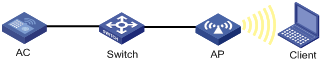
Configuration procedure
1. Create a service template named market, set the SSID to market, and enable the service template.
<AC> system-view
[AC] wlan service-template market
[AC-wlan-st-market] ssid market
[AC-wlan-st-market] service-template enable
[AC-wlan-st-market] quit
2. Create a manual AP named ap1, and specify the AP model and serial ID.
[AC] wlan ap ap1 model WA536-WW
[AC-wlan-ap-ap1] serial-id 219801A1NQB117012935
3. Configure SVP mapping:
# Enable WMM.
[AC-wlan-ap-ap1] radio 1
[AC-wlan-ap-ap1-radio-1] wmm enable
# Assign SVP packets to the AC-VO queue, and set EDCA parameters of AC-VO queues for clients.
[AC-wlan-ap-ap1-radio-1] wmm svp map-ac ac-vo
[AC-wlan-ap-ap1-radio-1] edca client ac-vo ecw ecwmin 0 ecwmax 0
# Bind service template market to radio 1, and enable the radio.
[AC-wlan-ap-ap1-radio-1] service-template market
[AC-wlan-ap-ap1-radio-1] radio enable
Verifying the configuration
# Verify that the AC assigns SVP packets to the AC-VO queue if a non-WMM client comes online and sends SVP packets to the AC.
Traffic differentiation configuration example
Network requirements
As shown in Figure 61, configure priority mapping on the AC to add 802.11 packets from the client to the AC-VO queue.
Configuration procedure
# Create a service template named market, and set the SSID to market.
<AC> system-view
[AC] wlan service-template market
[AC-wlan-st-market] ssid market
# Configure priority mapping, and enable the service template.
[AC-wlan-st-market] qos priority 7
[AC-wlan-st-market] service-template enable
[AC-wlan-st-market] quit
# Create a manual AP named ap1, and specify the AP model and serial ID.
[AC] wlan ap ap1 model WA536-WW
[AC-wlan-ap-ap1] serial-id 219801A1NQB117012935
# Enable WMM.
[AC-wlan-ap-ap1] radio 1
[AC-wlan-ap-ap1-radio-1] wmm enable
# Bind service template market to radio 1, and enable radio 1.
[AC-wlan-ap-ap1-radio-1] service-template market
[AC-wlan-ap-ap1-radio-1] radio enable
[AC-wlan-ap-ap1-radio-1] quit
[AC-wlan-ap-ap1] quit
Verifying the configuration
# Verify that packets from the client have been added to the AC-VO queue.
[AC] display wlan statistics client
MAC address : 0015-005e-97cc
AP name : ap1
Radio ID : 1
SSID : market
BSSID : 5866-ba74-e570
RSSI : 27
Sent frames:
Back ground : 0/0 (frames/bytes)
Best effort : 0/0 (frames/bytes)
Video : 0/0 (frames/bytes)
Voice : 14/1092 (frames/bytes)
Received frames:
Back ground : 0/0 (frames/bytes)
Best effort : 66/8177 (frames/bytes)
Video : 0/0 (frames/bytes)
Voice : 0/0 (frames/bytes)
Discarded frames:
Back ground : 0/0 (frames/bytes)
Best effort : 0/0 (frames/bytes)
Video : 0/0 (frames/bytes)
Voice : 0/0 (frames/bytes)
Bandwidth guaranteeing configuration example
Network requirements
As shown in Figure 62, Clients 1, 2, and 3 access the network through SSIDs research, office, and entertain, respectively.
For the network to operate correctly, guarantee 20% of the bandwidth for SSID office, 80% for research, and none for entertain.
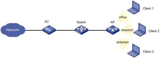
Configuration procedure
# Create a service template named office, set the SSID to office, and enable the service template.
<AC> system-view
[AC] wlan service-template office
[AC-wlan-st-office] ssid office
[AC-wlan-st-office] service-template enable
[AC-wlan-st-office] quit
# Create a service template named research, set the SSID to research, and enable the service template.
[AC] wlan service-template research
[AC-wlan-st-research] ssid research
[AC-wlan-st-research] service-template enable
[AC-wlan-st-research] quit
# Create a service template named entertain, set the SSID to entertain, and enable the service template.
[AC] wlan service-template entertain
[AC-wlan-st-entertain] ssid entertain
[AC-wlan-st-entertain] service-template enable
[AC-wlan-st-entertain] quit
# Set the maximum bandwidth to 10000 Kbps for the 802.11ac radio.
[AC] wlan max-bandwidth dot11ac 10000
# Create a manual AP named ap1, and specify the AP model and serial ID.
[AC] wlan ap ap1 model WA536-WW
[AC-wlan-ap-ap1] serial-id 219801A1NQB117012935
# Set the radio type to dot11ac for radio 1, bind service templates office, research, and entertain to radio 1, and enable radio 1.
[AC-wlan-ap-ap1] radio 1
[AC-wlan-ap-ap1-radio-1] type dot11ac
[AC-wlan-ap-ap1-radio-1] service-template office
[AC-wlan-ap-ap1-radio-1] service-template research
[AC-wlan-ap-ap1-radio-1] service-template entertain
[AC-wlan-ap-ap1-radio-1] radio enable
# Enable bandwidth guaranteeing.
[AC-wlan-ap-ap1-radio-1] bandwidth-guarantee enable
# Set the guaranteed bandwidth percentage to 20% for service template office and 80% for service template research.
[AC-wlan-ap-ap1-radio-1] bandwidth-guarantee service-template office percent 20
[AC-wlan-ap-ap1-radio-1] bandwidth-guarantee service-template research percent 80
[AC-wlan-ap-ap1-radio-1] return
Verifying the configuration
# Verify that the rate of traffic from the AP to any client is not limited when the total traffic rate is lower than 10000 Kbps.
# Send traffic from the AP to Client 1 and Client 2 at a rate of over 2000 Kbps and over 8000 Kbps, respectively, to verify the following items:
· The AP sends traffic to Client 1 at 2000 Kbps.
· The AP sends traffic to client 2 at 8000 Kbps.
· The rate of traffic from the AP to Client 3 is limited.
Client rate limiting configuration example
Network requirements
As shown in Figure 63, the AC is in the same network as the AP. Perform the following tasks on the AC:
· Configure static mode client rate limiting to limit the rate of incoming client traffic.
· Configure dynamic mode client rate limiting to limit the rate of outgoing client traffic.
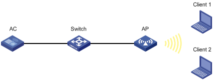
Configuration procedure
# Create a service template named service, and set its SSID to service.
<AC> system-view
[AC] wlan service-template service
[AC-wlan-st-service] ssid service
# Enable client rate limiting for service template service, and configure client rate limiting as follows:
· Limit the rate of incoming traffic to 8000 Kbps in static mode.
· Limit the rate of outgoing traffic to 8000 Kbps in dynamic mode.
[AC-wlan-st-service] client-rate-limit enable
[AC-wlan-st-service] client-rate-limit inbound mode static cir 8000
[AC-wlan-st-service] client-rate-limit outbound mode dynamic cir 8000
[AC-wlan-st-service] service-template enable
[AC-wlan-st-service] quit
# Create a manual AP named ap1, and specify the AP model and serial ID.
[AC] wlan ap ap1 model WA536-WW
[AC-wlan-ap-ap1] serial-id 219801A1NQB117012935
# Bind service template service to radio 1, and enable radio 1.
[AC-wlan-ap-ap1] radio 1
[AC-wlan-ap-ap1-radio-1] service-template service
[AC-wlan-ap-ap1-radio-1] radio enable
[AC-wlan-ap-ap1-radio-1] return
Configuring WLAN roaming
Overview
WLAN roaming enables clients to seamlessly roam among APs in an ESS while retaining their IP address and authorization information during the roaming process.
H3C ACs also support fast roaming, which enables RSN + 802.1X clients to roam to a new AP without being authenticated again.
Terminology
· Inter Access Controller Tunneling Protocol—IACTP is an H3C-proprietary protocol that provides a generic packet encapsulation and transport mechanism for ACs to securely communicate with each other. ACs providing roaming services establish an IACTP tunnel with each other to exchange control messages and client information.
· Home AC—A home AC is an AC that manages the AP with which a wireless client associates for the first time.
· Foreign AC—A foreign AC is an AC with which a client associates after inter-AC roaming.
WLAN roaming mechanism
Clients can roam between APs managed by ACs in the same mobility group.
Intra-AC roaming
Intra-AC roaming enables clients to roam among APs that are managed by the same AC.
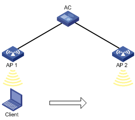
As shown in Figure 64, intra-AC roaming uses the following procedure:
1. The client comes online from AP 1, and the AC creates a roaming entry for the client.
2. The client roams to AP 2. The AC examines the roaming entry for the client and determines whether to perform fast roaming.
If the client is an RSN + 802.1X client, fast roaming is used, and the client can be associated with AP 2 without reauthentication. If it is not, the client needs to be reauthenticated before being associated with AP 2.
Inter-AC roaming
Inter-AC roaming enables clients to roam among APs that are managed by different ACs. These ACs must be in the same mobility group and have established an IACTP tunnel with each other.
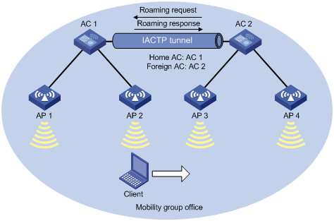
As shown in Figure 65, inter-AC roaming uses the following procedure:
1. The client comes online from AP 2. AC 1 creates a roaming entry for the client and sends the information to AC 2 through the IACTP tunnel.
2. The client roams to AP 3. AC 2 examines the roaming entry for the client and determines whether to perform fast roaming.
If the client is an RSN + 802.1X client, fast roaming is used, and the client can be associated with AP 3 without reauthentication. If it is not, the client needs to be reauthenticated before being associated with AP 3.
3. The client associates with AP 3. AC 2 sends a roaming request to AC 1.
4. AC 1 verifies the roaming request and performs either of the following operations:
? Sends a roaming response that indicates roaming failure to AC 2 if the request is invalid. AC 2 logs off the client.
? Saves the roaming trace and roam-out information and sends a roaming response that indicates roaming success to AC 2 if the request is valid. AC 2 saves roaming-in information for the client.
Configuration restrictions and guidelines
When you configure WLAN roaming, follow these restrictions and guidelines:
· For a service template where an AP is configured as the client authenticator, WLAN roaming is not supported. For more information about WLAN authentication, see "WLAN authentication overview" and "Configuring WLAN authentication."
· For RSN + 802.1X clients from different VLANs to roam between ACs within a mobility group, make sure uplink interfaces of the member ACs permit all client VLANs.
Configuration task list
|
Tasks at a glance |
|
(Required.) Creating a mobility group |
|
(Optional.) Setting an authentication mode for IACTP control messages |
|
(Required.) Specifying an IP address type for IACTP tunnels |
|
(Required.) Specifying the source IP address for establishing IACTP tunnels |
|
(Required.) Adding a mobility group member |
|
(Required.) Enabling a mobility group |
|
(Optional.) Enabling tunnel isolation for mobility groups |
|
(Optional.) Enabling SNMP notifications for WLAN roaming |
Creating a mobility group
For inter-AC roaming to operate correctly, create the same mobility group and add members to each AC in the mobility group.
To create a mobility group:
|
Command |
Remarks |
|
|
1. Enter system view. |
N/A |
|
|
2. Create a mobility group. |
By default, no mobility group exists on the AC. You can create only one mobility group on the AC. |
Setting an authentication mode for IACTP control messages
This feature enables the AC to verify the integrity of control messages transmitted over IACTP tunnels. WLAN roaming supports only the 128-bit MD5 algorithm.
To set an authentication mode for IACTP control messages:
|
Step |
Command |
Remarks |
|
1. Enter system view. |
system-view |
N/A |
|
2. Enter mobility group view. |
wlan mobility group group-name |
N/A |
|
3. Set an authentication mode for IACTP control messages. |
authentication-mode authentication-mode { cipher | simple } authentication-key |
By default, no authentication mode is set for IACTP control messages. The AC does not verify the integrity of IACTP control messages. |
Specifying an IP address type for IACTP tunnels
You must specify an IP address type for IACTP tunnels after you create a mobility group.
To specify an IP address type for IACTP tunnels:
|
Step |
Command |
Remarks |
|
1. Enter system view. |
system-view |
N/A |
|
2. Enter mobility group view. |
wlan mobility group group-name |
N/A |
|
3. Specify an IP address type for IACTP tunnels. |
By default, the IP address type for IACTP tunnels is IPv4. You cannot specify both IPv4 and IPv6 address types for IACTP tunnels. |
Specifying the source IP address for establishing IACTP tunnels
When you specify the source IP address for establishing IACTP tunnels, follow these restrictions and guidelines:
· Make sure the mobility group is disabled before you specify the source IP address for establishing IACTP tunnels.
· You can specify one IPv4 address, one IPv6 address, or both, but only the IP address type that is the same as the IP address type for IACTP tunnels takes effect.
To specify the source IP address for establishing IACTP tunnels:
|
Step |
Command |
Remarks |
|
1. Enter system view. |
system-view |
N/A |
|
2. Enter mobility group view. |
wlan mobility group group-name |
N/A |
|
3. Specify the source IP address for establishing IACTP tunnels. |
By default, no source IP address is specified for establishing IACTP tunnels. |
Adding a mobility group member
Members in a mobility group are identified by their IP addresses used to establish IACTP tunnels.
You can add both IPv4 and IPv6 members to a mobility group. Only members whose IP address type is the same as the IP address type of IACTP tunnels take effect.
An AC can belong to only one mobility group.
You can add a maximum of 31 IPv4 members and 31 IPv6 members to a mobility group.
You can specify VLANs for a member, so that other members in the mobility group can directly forward client data of the member from the specified VLANs. If you do not specify VLANs for the member, its client data cannot be directly forwarded by another member in the mobility group unless the clients roam to that member.
When you specify VLANs for a mobility group member, follow these restrictions and guidelines:
· If a mobility group has multiple members, make sure no loops exist among IACTP tunnels between members within the mobility group.
· Make sure the VLANs have not been used by interfaces or services.
· Do not assign VLANs that have been specified for a member to interfaces or services.
To add a mobility group member:
|
Step |
Command |
Remarks |
|
1. Enter system view. |
system-view |
N/A |
|
2. Enter mobility group view. |
wlan mobility group group-name |
N/A |
|
3. Add a mobility group member. |
member { ip ip-address | ipv6 ipv6-address } [ vlan vlan-id-list ] |
By default, a mobility group does not have any members. |
Enabling a mobility group
This feature enables the AC to establish IACTP tunnels and synchronize roaming entries with member ACs.
To enable a mobility group:
|
Step |
Command |
Remarks |
|
1. Enter system view. |
system-view |
N/A |
|
2. Enter mobility group view. |
wlan mobility group group-name |
N/A |
|
3. Enable the mobility group. |
group enable |
By default, a mobility group is disabled. |
Enabling tunnel isolation for mobility groups
Use this feature when loops exist among ACs in a mobility group. It prevents ACs from forwarding packets between tunnels in the mobility group and avoids broadcast storm.
To enable tunnel isolation for mobility groups:
|
Step |
Command |
Remarks |
|
1. Enter system view. |
system-view |
N/A |
|
2. Enable tunnel isolation for mobility groups. |
wlan mobility-group-isolation enable |
By default, tunnel isolation is enabled for mobility groups. |
Enabling SNMP notifications for WLAN roaming
To report critical WLAN roaming events to an NMS, enable SNMP notifications for WLAN roaming. For WLAN roaming event notifications to be sent correctly, you must also configure SNMP as described in Network Management and Monitoring Configuration Guide.
To enable SNMP notifications for WLAN roaming:
|
Step |
Command |
Remarks |
|
1. Enter system view. |
system-view |
N/A |
|
2. Enable SNMP notifications for WLAN roaming. |
snmp-agent trap enable wlan mobility |
By default, SNMP notifications for WLAN roaming are disabled. |
Displaying and maintaining WLAN roaming
Execute display commands in any view.
|
Task |
Command |
|
Display roam-track information for a client on the home AC. |
|
|
Display mobility group information. |
|
|
Display information about clients that have roamed to or from the AC. |
display wlan mobility { roam-in | roam-out } [ member { ip ipv4-address | ipv6 ipv6-address } ] |
WLAN roaming configuration examples
Configuring intra-AC roaming
Network requirements
As shown in Figure 64, configure intra-AC roaming to enable the client to roam from AP 1 to AP 2 that are managed by the same AC.
Configuration procedures
# Create a service template named service, set the SSID to 1, and enable the service template.
[AC] wlan service-template service
[AC-wlan-st-service] ssid 1
[AC-wlan-st-service] service-template enable
[AC-wlan-st-service] quit
# Create a manual AP named ap1, and specify the AP model and serial ID.
[AC] wlan ap ap1 model WA536-WW
[AC-wlan-ap-ap1] serial-id 219801A1NQB117012935
# Bind the service template to radio 1 of AP 1.
[AC-wlan-ap-ap1-radio-1] radio enable
[AC-wlan-ap-ap1-radio-1] service-template service
[AC-wlan-ap-ap1-radio-1] quit
[AC-wlan-ap-ap1] quit
# Create a manual AP named ap2, and specify the AP model and serial ID.
[AC] wlan ap ap2 model WA536-WW
[AC-wlan-ap-ap2] serial-id 219801A1NQB117012946
# Bind the service template to radio 1 of AP 2.
[AC-wlan-ap-ap2-radio-1] radio enable
[AC-wlan-ap-ap2-radio-1] service-template service
[AC-wlan-ap-ap2-radio-1] quit
[AC-wlan-ap-ap2] quit
Verifying the configuration
# Get the client online on AP 1. (Details not shown.)
# Verify that the client associates with AP 1, and the roaming status is N/A, which indicates that the client has not performed any roaming.
[AC] display wlan client verbose
Total number of clients: 1
MAC address : 9cd3-6d9e-6778
IPv4 address : 10.1.1.114
IPv6 address : N/A
Username : N/A
AID : 1
AP ID : 1
AP name : ap1
Radio ID : 1
SSID : 1
BSSID : 000f-e200-4444
VLAN ID : 1
Sleep count : 242
Wireless mode : 802.11ac
Channel bandwidth : 80MHz
SM power save : Enabled
SM power save mode : Dynamic
Short GI for 20MHz : Supported
Short GI for 40MHz : Supported
Short GI for 80MHz : Supported
Short GI for 160/80+80MHz : Not supported
STBC RX capability : Not supported
STBC TX capability : Not supported
LDPC RX capability : Not supported
SU beamformee capability : Not supported
MU beamformee capability : Not supported
Beamformee STS capability : N/A
Block Ack : TID 0 In
Supported VHT-MCS set : NSS1 0, 1, 2, 3, 4, 5, 6, 7, 8
NSS2 0, 1, 2, 3, 4, 5, 6, 7, 8
Supported HT MCS set : 0, 1, 2, 3, 4, 5, 6, 7,
8, 9, 10, 11, 12, 13, 14,
15, 16, 17, 18, 19, 20,
21, 22, 23
Supported rates : 6, 9, 12, 18, 24, 36,
48, 54 Mbps
QoS mode : WMM
Listen interval : 10
RSSI : 62
Rx/Tx rate : 130/11
Authentication method : Open system
Security mode : PRE-RSNA
AKM mode : Not configured
Cipher suite : N/A
User authentication mode : Bypass
Authorization ACL ID : 3001(Not effective)
Authorization user profile : N/A
Roam status : N/A
Key derivation : SHA1
PMF status : Enabled
Forward policy name : Not configured
Online time : 0days 0hours 1minutes 13seconds
FT status : Inactive
# Verify that the AC has a roaming entry for the client.
[AC] display wlan mobility roam-track mac-address 9cd3-6d9e-6778
Total entries: 1
BSSID Created at Online time AC IP address RID AP name
000f-e200-4444 2017-03-14 11:12:28 00hr 01min 16sec 127.0.0.1 1 ap1
# Make the client roam to AP 2. (Details not shown.)
# Verify that the client has associated with AP 2, and the roaming status is Intra-AC roam.
[AC] display wlan client verbose
Total number of clients: 1
MAC address : 9cd3-6d9e-6778
IPv4 address : 10.1.1.114
IPv6 address : N/A
Username : N/A
AID : 1
AP ID : 2
AP name : ap2
Radio ID : 1
SSID : 1
BSSID : 000f-e203-7777
VLAN ID : 1
Sleep count : 242
Wireless mode : 802.11ac
Channel bandwidth : 80MHz
SM power save : Enabled
SM power save mode : Dynamic
Short GI for 20MHz : Supported
Short GI for 40MHz : Supported
Short GI for 80MHz : Supported
Short GI for 160/80+80MHz : Not supported
STBC RX capability : Not supported
STBC TX capability : Not supported
LDPC RX capability : Not supported
SU beamformee capability : Not supported
MU beamformee capability : Not supported
Beamformee STS capability : N/A
Block Ack : TID 0 In
Supported VHT-MCS set : NSS1 0, 1, 2, 3, 4, 5, 6, 7, 8
NSS2 0, 1, 2, 3, 4, 5, 6, 7, 8
Supported HT MCS set : 0, 1, 2, 3, 4, 5, 6, 7,
8, 9, 10, 11, 12, 13, 14,
15, 16, 17, 18, 19, 20,
21, 22, 23
Supported rates : 6, 9, 12, 18, 24, 36,
48, 54 Mbps
QoS mode : WMM
Listen interval : 10
RSSI : 62
Rx/Tx rate : 130/11
Authentication method : Open system
Security mode : PRE-RSNA
AKM mode : Not configured
Cipher suite : N/A
User authentication mode : Bypass
Authorization ACL ID : 3001(Not effective)
Authorization user profile : N/A
Roam status : Intra-AC roam
Key derivation : SHA1
PMF status : Enabled
Forward policy name : Not configured
Online time : 0days 0hours 5minutes 13seconds
FT status : Inactive
# Verify that the AC has updated the roaming entry for the client.
[AC] display wlan mobility roam-track mac-address 9cd3-6d9e-6778
Total entries: 2
BSSID Created at Online time AC IP address RID AP name
000f-e203-7777 2017-03-14 11:12:28 00hr 01min 02sec 127.0.0.1 1 ap2
000f-e200-4444 2017-03-14 11:12:04 00hr 03min 51sec 127.0.0.1 1 ap1
Configuring inter-AC roaming
Network requirements
As shown in Figure 65, configure inter-AC roaming to enable the client to roam from AP 2 to AP 3 that are managed by different ACs.
Configuration procedures
1. Configure AC 1:
# Create a service template named service, set the SSID to office, and enable the service template.
[AC1] wlan service-template service
[AC1-wlan-st-test] ssid office
[AC1-wlan-st-test] service-template enable
[AC1-wlan-st-test] quit
# Create a manual AP named ap1, and specify the AP model and serial ID.
[AC1] wlan ap ap1 model WA536-WW
[AC1-wlan-ap-ap1] serial-id 219801A1NQB117012935
# Bind the service template to radio 1 of AP 1.
[AC1-wlan-ap-ap1] radio 1
[AC1-wlan-ap-ap1-radio-1] radio enable
[AC1-wlan-ap-ap1-radio-1] service-template service
[AC1-wlan-ap-ap1-radio-1] quit
[AC1-wlan-ap-ap1] quit
# Create a manual AP named ap2, and specify the AP model and serial ID.
[AC1] wlan ap ap2 model WA536-WW
[AC1-wlan-ap-ap2] serial-id 219801A1NQB117012946
# Bind the service template to radio 1 of AP 2.
[AC1-wlan-ap-ap2-radio-1] radio enable
[AC1-wlan-ap-ap2-radio-1] service-template service
[AC1-wlan-ap-ap2-radio-1] quit
[AC1-wlan-ap-ap2] quit
# Create a mobility group named office.
[AC1] wlan mobility group office
# Specify the IP address type for IACTP tunnels as IPv4.
[AC1-wlan-mg-office] tunnel-type ipv4
# Specify the source IP address for establishing IACTP tunnels as 10.1.4.22.
[AC1-wlan-mg-office] source ip 10.1.4.22
# Add AC 2 to the mobility group.
[AC1-wlan-mg-office] member ip 10.1.4.23
# Enable the mobility group.
[AC1-wlan-mg-office] group enable
[AC1-wlan-mg-office] quit
2. Configure AC 2:
# Create a service template named service, specify the SSID as office, and enable the service template.
[AC2] wlan service-template service
[AC2-wlan-st-service] ssid office
[AC2-wlan-st-service] service-template enable
[AC2-wlan-st-service] quit
# Create a manual AP named ap3, and specify the AP model and serial ID.
[AC2] wlan ap ap3 model WA536-WW
[AC2-wlan-ap-ap3] serial-id 219801A1NQB117012957
# Bind the service template to radio 1 of AP 3.
[AC2-wlan-ap-ap3-radio-1] radio enable
[AC2-wlan-ap-ap3-radio-1] service-template service
[AC2-wlan-ap-ap3-radio-1] quit
[AC2-wlan-ap-ap3] quit
# Create a manual AP named ap4, and specify the AP model and serial ID.
[AC2] wlan ap ap4 model WA536-WW
[AC2-wlan-ap-ap4] serial-id 219801A1NQB117012988
# Bind the service template to radio 1 of AP 4.
[AC2-wlan-ap-ap4] radio 1
[AC2-wlan-ap-ap4-radio-1] radio enable
[AC2-wlan-ap-ap4-radio-1] service-template service
[AC2-wlan-ap-ap4-radio-1] quit
[AC2-wlan-ap-ap4] quit
# Create a mobility group named office.
[AC2] wlan mobility group office
# Specify the IP address type for IACTP tunnels as IPv4.
[AC2-wlan-mg-office] tunnel-type ipv4
# Specify the source IP address for establishing IACTP tunnels as 10.1.4.23.
[AC2-wlan-mg-office] source ip 10.1.4.23
# Add AC 2 to the mobility group.
[AC2-wlan-mg-office] member ip 10.1.4.22
# Enable the mobility group.
[AC2-wlan-mg-office] group enable
[AC2-wlan-mg-office] quit
Verifying the configuration
# Verify that a mobility group has been created on AC 1.
[AC1] display wlan mobility group
Mobility group name: office
Tunnel type: IPv4
Source IPv4: 10.1.4.22
Source IPv6: Not configured
Authentication method: Not configured
Mobility group status: Enabled
Member entries: 1
IP address State Online time
10.1.4.23 Up 00hr 00min 12sec
# Verify that a mobility group has been created on AC 2.
[AC2] display wlan mobility group
Mobility group name: office
Tunnel type: IPv4
Source IPv4: 10.1.4.23
Source IPv6: Not configured
Authentication method: Not configured
Mobility group status: Enabled
Member entries: 1
IP address State Online time
10.1.4.22 Up 00hr 00min 05sec
# Get the client online on AP 2 and then make the client roam to AP 3. (Details not shown.)
# Display client roaming information on AC 1 to verify that the client came online from AP 2 and roamed to AP 3.
[AC1] display wlan mobility roam-track mac-address 9cd3-6d9e-6778
Total entries: 2
BSSID Created at Online time AC IP address RID AP name
000f-e203-8889 2017-03-14 11:12:28 00hr 06min 56sec 10.1.4.23 1 ap3
000f-e203-7777 2017-03-14 11:11:28 00hr 03min 30sec 127.0.0.1 1 ap2
# On AC 1, verify that the client has roamed to AC 3.
<AC1> display wlan mobility roam-out
Total entries: 1
MAC address BSSID VLAN ID Online time FA IP address
9cd3-6d9e-6778 000f-e203-8889 1 00hr 01min 59sec 10.1.4.23
# On AC 2, verify that the client has associated with AP 3, and the roaming status is Inter-AC roam.
<AC2> display wlan client verbose
Total number of clients: 1
MAC address : 9cd3-6d9e-6778
IPv4 address : 10.1.1.114
IPv6 address : N/A
Username : N/A
AID : 1
AP ID : 3
AP name : ap3
Radio ID : 1
SSID : 1
BSSID : 000f-e203-8889
VLAN ID : 1
Sleep count : 242
Wireless mode : 802.11ac
Channel bandwidth : 80MHz
SM power save : Enabled
SM power save mode : Dynamic
Short GI for 20MHz : Supported
Short GI for 40MHz : Supported
Short GI for 80MHz : Supported
Short GI for 160/80+80MHz : Not supported
STBC RX capability : Not supported
STBC TX capability : Not supported
LDPC RX capability : Not supported
SU beamformee capability : Not supported
MU beamformee capability : Not supported
Beamformee STS capability : N/A
Block Ack : TID 0 In
Supported VHT-MCS set : NSS1 0, 1, 2, 3, 4, 5, 6, 7, 8
NSS2 0, 1, 2, 3, 4, 5, 6, 7, 8
Supported HT MCS set : 0, 1, 2, 3, 4, 5, 6, 7,
8, 9, 10, 11, 12, 13, 14,
15, 16, 17, 18, 19, 20,
21, 22, 23
Supported rates : 6, 9, 12, 18, 24, 36,
48, 54 Mbps
QoS mode : WMM
Listen interval : 10
RSSI : 62
Rx/Tx rate : 130/11
Authentication method : Open system
Security mode : PRE-RSNA
AKM mode : Not configured
Cipher suite : N/A
User authentication mode : Bypass
Authorization ACL ID : 3001(Not effective)
Authorization user profile : N/A
Roam status : Inter-AC roam
Key derivation : SHA1
PMF status : Enabled
Forward policy name : Not configured
Online time : 0days 0hours 5minutes 13seconds
FT status : Inactive
# Verify that the client has roamed from AC 1 to AC 3.
<AC2> display wlan mobility roam-in
Total entries: 1
MAC address BSSID VLAN ID HA IP address
9cd3-6d9e-6778 000f-e203-8889 1 10.1.4.22
Configuring WLAN load balancing
This chapter assumes that an AP has only one radio enabled.
Overview
WLAN load balancing dynamically loads balance clients across APs to ensure wireless service quality and adequate bandwidth for clients in high-density WLANs.
Implementation prerequisites
To implement WLAN load balancing among specific APs, the APs must be managed by the same AC, and the clients can discover the APs. As shown in Figure 66, load balancing is enabled on AP 1, AP 2, and AP 3 that are managed by the same AC. AP 3 has reached its maximum load. When Client 5 tries to associate with AP 3, the AC rejects the association request and directs Client 5 to AP 1 or AP 2. However, if Client 5 can only discover AP 3, it continues to send association requests to AP 3. If the number of times that AP 3 rejects Client 5 reaches the specified maximum number of denials for association requests, AP 3 accepts Client 5's association request.
Figure 66 Implementation prerequisites
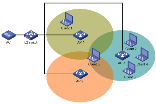
Work mechanism
The AC performs load balancing when the following conditions are met:
· The load of an AP reaches the threshold.
· The load gap between the AP and the AP that has the lightest load reaches the load gap threshold.
When the load and load gap for the AP reach their respective threshold, the AP rejects the association request of a client. If the number of times that the AP rejects the client reaches the specified maximum number of denials for association requests, the AP accepts the client's association request.
Load balancing modes
The AC supports session-mode, traffic-mode, and bandwidth-mode load balancing. It performs load balancing of a specific mode when the following conditions are met:
· The specified session/traffic/bandwidth threshold is reached.
· The specified session/traffic/bandwidth gap threshold is reached.
Session-mode load balancing
As shown in Figure 67, Client 1 associates with AP 1, and Client 2 through Client 4 associate with AP 2. Assume that the session threshold and session gap threshold are set to 3 and 2, respectively. When Client 5 tries to associate with AP 2, AP 2 rejects the request because both the session threshold and session gap threshold are reached.
Figure 67 Session-mode load balancing
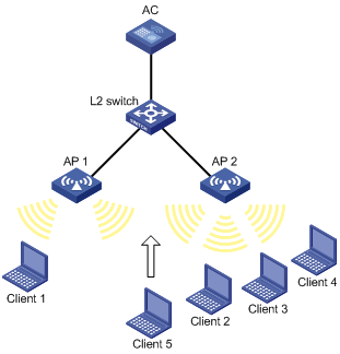
Traffic-mode load balancing
As shown in Figure 68, Client 1 associates with AP 1, and Client 2 associates with AP 2. When the traffic of AP 1 and the traffic gap between AP 1 and AP 2 reach their respective threshold, AP 1 rejects the association request from Client 3.
Figure 68 Traffic-mode load balancing

Bandwidth-mode load balancing
As shown in Figure 69, Client 1 associates with AP 1, and Client 2 associates with AP 2. When the bandwidth of AP 1 and the bandwidth gap between AP 1 and AP 2 reach their respective thresholds, AP 1 rejects the association request from Client 3.
Figure 69 Bandwidth-mode load balancing

Load balancing types
The AC supports the following load balancing types:
· Radio based—The AC determines the APs that will participate in load balancing based on the neighbor reports of the APs. The neighbor report of an AP records the MAC address and RSSI value of each client that is detected by the AP. The AC determines that an AP will participate in load balancing when either of the following conditions is met:
? A client requests to associate with the AP and the AP detects that RSSI of the client is lower than the RSSI threshold.
? The AP detects that a client's RSSI has reached the RSSI threshold but the client does not request to associate with the AP.
· Load balancing group based—You add the radios of desired APs to a load balancing group. The AC does not perform load balancing on radios that do not belong to the load balancing group.
Configuration task list
|
Tasks at a glance |
Remarks |
|
(Required.) Enabling WLAN load balancing |
N/A |
|
(Required.) Setting a load balancing mode |
N/A |
|
(Optional.) Configuring a load balancing group |
If you do not create any load balancing groups, the AC performs radio-based load balancing. |
|
(Optional.) Configuring load balancing parameters |
N/A |
|
(Optional.) Enabling SNMP notifications for WLAN load balancing |
N/A |
Configuring WLAN load balancing
Before you configure load balancing, make sure the fast association function is disabled. For more information about fast association, see "Configuring WLAN access."
Enabling WLAN load balancing
|
Step |
Command |
Remarks |
|
1. Enter system view. |
system-view |
N/A |
|
2. Enable WLAN load balancing. |
wlan load-balance enable |
By default, WLAN load balancing is disabled. |
Setting a load balancing mode
|
Command |
Remarks |
|
|
1. Enter system view. |
system-view |
N/A |
|
2. Set a load balancing mode. |
· Set session-mode load balancing: · Set traffic-mode load balancing: · Set bandwidth-mode load balancing: |
By default, session-mode load balancing is used. |
Configuring a load balancing group
|
Step |
Command |
Remarks |
|
1. Enter system view. |
system-view |
N/A |
|
2. Create a load balancing group and enter its view. |
wlan load-balance group group-id |
By default, no load balancing group exists. |
|
3. Add a radio of an AP to the load balancing group. |
ap name ap-name radio radio-id |
By default, no radio exists in the load balancing group. |
|
4. (Optional.) Set a description for the load balancing group. |
description text |
By default, no description is set for the load balancing group. |
Configuring load balancing parameters
The following parameters affect load balancing calculation:
· Load balancing RSSI threshold—If an AP detects that the RSSI of a client is lower than the specified RSSI threshold, the AP performs either of the following operations:
? If multiple APs can detect the client, the AP participates in load balancing only when the client requests to associate with the AP.
? If only this AP can detect the client, the AP decreases the maximum number of denials to 1 so that the client has more chances to associate with the AP.
· Maximum number of denials for association requests—If the number of times that an AP rejects a client reaches the specified maximum number of denials for association requests, the AP accepts the association request of the client.
To configure load balancing parameters:
|
Step |
Command |
Remarks |
|
1. Enter system view. |
system-view |
N/A |
|
2. Set the RSSI threshold. |
wlan load-balance rssi-threshold rssi-threshold |
By default, the RSSI threshold is 25. |
|
3. Set the maximum number of denials for association requests. |
wlan load-balance access-denial access-denial |
By default, the maximum number of denials is 10 for association requests. |
Enabling SNMP notifications for WLAN load balancing
To report critical WLAN load balancing events to an NMS, enable SNMP notifications for WLAN load balancing. For WLAN load balancing event notifications to be sent correctly, you must also configure SNMP as described in Network Management and Monitoring Configuration Guide.
To enable SNMP notifications for WLAN load balancing:
|
Step |
Command |
Remarks |
|
1. Enter system view. |
system-view |
N/A |
|
2. Enable SNMP notifications for WLAN load balancing. |
snmp-agent trap enable wlan load-balance |
By default, SNMP notifications for WLAN load balancing are disabled. |
Displaying and maintaining WLAN load balancing
Execute the display command in any view.
|
Task |
Command |
|
Display load balancing group information. |
display wlan load-balance group { group-id | all } |
WLAN load balancing configuration examples (for radios)
Configuring session-mode load balancing
Network requirements
As shown in Figure 70, AP 1 and AP 2 are managed by the AC and the clients can discover the APs.
Configure the AC to perform session-mode load balancing on AP 1 and AP 2 when the following conditions are met:
· The number of sessions on one AP reaches 3.
· The session gap between the APs reaches 2.

Configuration procedure
# Create wireless service template 1, and set its SSID to session-balance.
<AC> system-view
[AC] wlan service-template 1
[AC-wlan-st-1] ssid session-balance
[AC-wlan-st-1] service-template enable
[AC-wlan-st-1] quit
# Create the AP template ap1, and specify the model and serial ID.
[AC] wlan ap ap1 model WA536-WW
[AC-wlan-ap-ap1] serial-id 219801A1NQB117012935
# Bind service template 1 to radio 2 of AP 1.
[AC-wlan-ap-ap1] radio 2
[AC-wlan-ap-ap1-radio-2] service-template 1
[AC-wlan-ap-ap1-radio-2] radio enable
[AC-wlan-ap-ap1-radio-2] quit
[AC-wlan-ap-ap1] quit
# Create the AP template ap2, and specify the model and serial ID.
[AC] wlan ap ap2 model WA536-WW
[AC-wlan-ap-ap2] serial-id 219801A1NQB117012945
# Bind service template 1 to radio 2 of AP 2.
[AC-wlan-ap-ap2] radio 2
[AC-wlan-ap-ap2-radio-2] service-template 1
[AC-wlan-ap-ap2-radio-2] radio enable
[AC-wlan-ap-ap2-radio-2] quit
[AC-wlan-ap-ap2] quit
# Set the load balancing mode to session mode, and set the session threshold and session gap threshold to 3 and 2, respectively.
[AC] wlan load-balance mode session 3 gap 2
# Enable WLAN load balancing.
[AC] wlan load-balance enable
Verifying the configuration
# Verify that the AC performs session-mode load balancing for AP 1 and AP 2 when the following conditions are met:
· The number of sessions on one AP reaches 3.
· The session gap between the APs reaches 2. (Details not shown.)
# Verify that AP 1 and AP 2 are load balanced by using the display wlan client command. (Details not shown.)
Configuring traffic-mode load balancing
Network requirements
As shown in Figure 71, AP 1 and AP 2 are managed by the AC and the clients can discover the APs. The maximum bandwidth for each AP is 150 Mbps.
Configure the AC to perform traffic-mode load balancing on AP 1 and AP 2 when the following conditions are met:
· The traffic of one AP reaches 30 Mbps (20% of the maximum bandwidth).
· The traffic gap between the APs reaches 15 Mbps (10% of the maximum bandwidth).

Configuration procedure
# Create wireless service template 1, and set its SSID to traffic-balance.
<AC> system-view
[AC] wlan service-template 1
[AC-wlan-st-1] ssid traffic-balance
[AC-wlan-st-1] service-template enable
[AC-wlan-st-1] quit
# Create the AP template ap1, and specify the model and serial ID.
[AC] wlan ap ap1 model WA536-WW
[AC-wlan-ap-ap1] serial-id 219801A1NQB117012935
# Bind service template 1 to radio 2 of AP 1.
[AC-wlan-ap-ap1] radio 2
[AC-wlan-ap-ap1-radio-2] service-template 1
[AC-wlan-ap-ap1-radio-2] radio enable
[AC-wlan-ap-ap1-radio-2] quit
[AC-wlan-ap-ap1] quit
# Create the AP template ap2, and specify the model and serial ID.
[AC] wlan ap ap2 model WA536-WW
[AC-wlan-ap-ap2] serial-id 219801A1NQB117012945
# Bind service template 1 to radio 2 of AP 2.
[AC-wlan-ap-ap2] radio 2
[AC-wlan-ap-ap2-radio-2] service-template 1
[AC-wlan-ap-ap2-radio-2] radio enable
[AC-wlan-ap-ap2-radio-2] quit
[AC-wlan-ap-ap2] quit
# Set the load balancing mode to traffic mode, and set the traffic threshold and traffic gap threshold to 20% and 10%, respectively.
[AC] wlan load-balance mode traffic 20 gap 10
# Enable WLAN load balancing.
[AC] wlan load-balance enable
Verifying the configuration
# Verify that the AC performs traffic-mode load balancing for AP 1 and AP 2 when the following conditions are met:
· The traffic of one AP reaches 30 Mbps.
· The traffic gap between the APs reaches 15 Mbps. (Details not shown.)
# Verify that AP 1 and AP 2 are load balanced by using the display wlan client command. (Details not shown.)
Configuring bandwidth-mode load balancing
Network requirements
As shown in Figure 72, AP 1 and AP 2 are managed by the AC and the clients can discover the APs.
Configure the AC to perform bandwidth-mode load balancing on AP 1 and AP 2 when the following conditions are met:
· The bandwidth of one AP reaches 12 Mbps.
· The bandwidth gap between the APs reaches 3 Mbps.
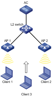
Configuration procedure
# Create wireless service template 1, and set its SSID to bandwidth-balance.
<AC> system-view
[AC] wlan service-template 1
[AC-wlan-st-1] ssid bandwidth-balance
[AC-wlan-st-1] service-template enable
[AC-wlan-st-1] quit
# Create the AP template ap1, and specify the model and serial ID.
[AC] wlan ap ap1 model WA536-WW
[AC-wlan-ap-ap1] serial-id 219801A1NQB117012935
# Bind service template 1 to radio 2 of AP 1.
[AC-wlan-ap-ap1] radio 2
[AC-wlan-ap-ap1-radio-2] service-template 1
[AC-wlan-ap-ap1-radio-2] radio enable
[AC-wlan-ap-ap1-radio-2] quit
[AC-wlan-ap-ap1] quit
# Create the AP template ap2, and specify the model and serial ID.
[AC] wlan ap ap2 model WA536-WW
[AC-wlan-ap-ap2] serial-id 219801A1NQB117012945
# Bind service template 1 to radio 2 of AP 2.
[AC-wlan-ap-ap2] radio 2
[AC-wlan-ap-ap2-radio-2] service-template 1
[AC-wlan-ap-ap2-radio-2] radio enable
[AC-wlan-ap-ap2-radio-2] quit
[AC-wlan-ap-ap2] quit
# Set the load balancing mode to bandwidth mode, and set the bandwidth threshold and bandwidth gap threshold to 12 Mbps and 3 Mbps, respectively.
[AC] wlan load-balance mode bandwidth 12 gap 3
# Enable WLAN load balancing.
[AC] wlan load-balance enable
Verifying the configuration
# Verify that the AC performs bandwidth-mode load balancing for AP 1 and AP 2 when the following conditions are met:
· The bandwidth of one AP reaches 12 Mbps.
· The bandwidth gap between the APs reaches 3 Mbps. (Details not shown.)
# Verify that AP 1 and AP 2 are load balanced by using the display wlan client command. (Details not shown.)
WLAN load balancing configuration examples (for a load balancing group)
Configuring session-mode load balancing
Network requirements
As shown in Figure 73, AP 1, AP 2, and AP 3 are managed by the AC and the clients can discover the APs.
Configure the AC to perform session-mode load balancing on radio 2 of AP 1 and radio 2 of AP 2 when the following conditions are met:
· The number of sessions on one radio reaches 3.
· The session gap between the radios reaches 2.
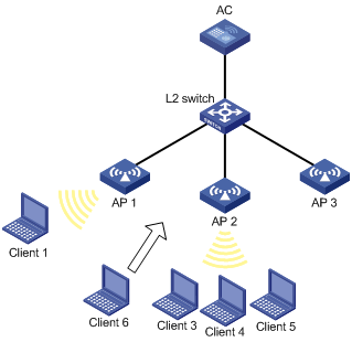
Configuration procedure
# Create wireless service template 1, and set its SSID to session-balance.
<AC> system-view
[AC] wlan service-template 1
[AC-wlan-st-1] ssid session-balance
[AC-wlan-st-1] service-template enable
[AC-wlan-st-1] quit
# Create the AP template ap1, and specify the model and serial ID.
[AC] wlan ap ap1 model WA536-WW
[AC-wlan-ap-ap1] serial-id 219801A1NQB117012935
# Bind service template 1 to radio 2 of AP 1.
[AC-wlan-ap-ap1] radio 2
[AC-wlan-ap-ap1-radio-2] service-template 1
[AC-wlan-ap-ap1-radio-2] radio enable
[AC-wlan-ap-ap1-radio-2] quit
[AC-wlan-ap-ap1] quit
# Create the AP template ap2, and specify the model and serial ID.
[AC] wlan ap ap2 model WA536-WW
[AC-wlan-ap-ap2] serial-id 219801A1NQB117012945
# Bind service template 1 to radio 2 of AP 2.
[AC-wlan-ap-ap2] radio 2
[AC-wlan-ap-ap2-radio-2] service-template 1
[AC-wlan-ap-ap2-radio-2] radio enable
[AC-wlan-ap-ap2-radio-2] quit
[AC-wlan-ap-ap2] quit
# Create the AP template ap3, and specify the model and serial ID.
[AC] wlan ap ap3 model WA536-WW
[AC-wlan-ap-ap3] serial-id 219801A1NQB117012938
# Bind service template 1 to radio 2 of AP 3.
[AC-wlan-ap-ap3] radio 2
[AC-wlan-ap-ap3-radio-2] service-template 1
[AC-wlan-ap-ap3-radio-2] radio enable
[AC-wlan-ap-ap3-radio-2] quit
[AC-wlan-ap-ap3] quit
# Set the load balancing mode to session mode, and set the session threshold and session gap threshold to 3 and 2, respectively.
[AC] wlan load-balance mode session 3 gap 2
# Create load balancing group 1.
[AC] wlan load-balance group 1
# Add radio 2 of AP 1 and radio 2 of AP 2 to load balancing group 1.
[AC-wlan-lb-group-1] ap name ap1 radio 2
[AC-wlan-lb-group-1] ap name ap2 radio 2
# Enable WLAN load balancing.
[AC] wlan load-balance enable
Verifying the configuration
# Verify that the AC performs session-mode load balancing for radio 2 of AP 1 and radio 2 of AP 2 when the following conditions are met:
· The number of sessions on one radio reaches 3.
· The session gap between the radios reaches 2. (Details not shown.)
# Verify that AP 1 and AP 2 are load balanced by using the display wlan client command. (Details not shown.)
Configuring traffic-mode load balancing
Network requirements
As shown in Figure 74, AP 1, AP 2, and AP 3 are managed by the AC and the clients can discover the APs. The maximum bandwidth for each AP is 150 Mbps.
Configure the AC to perform traffic-mode load balancing on radio 2 of AP 1 and radio 2 of AP 2 when the following conditions are met:
· The traffic of one radio reaches 30 Mbps (20% of the maximum bandwidth).
· The traffic gap between the radios reaches 15 Mbps (10% of the maximum bandwidth).
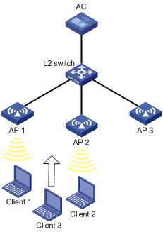
Configuration procedure
# Create wireless service template 1, and set its SSID to traffic-balance.
<AC> system
[AC] wlan service-template 1
[AC-wlan-st-1] ssid traffic-balance
[AC-wlan-st-1] service-template enable
[AC-wlan-st-1] quit
# Create the AP template ap1, and specify the model and serial ID.
[AC] wlan ap ap1 model WA536-WW
[AC-wlan-ap-ap1] serial-id 219801A1NQB117012935
# Bind service template 1 to radio 2 of AP 1.
[AC-wlan-ap-ap1] radio 2
[AC-wlan-ap-ap1-radio-2] service-template 1
[AC-wlan-ap-ap1-radio-2] radio enable
[AC-wlan-ap-ap1-radio-2] quit
[AC-wlan-ap-ap1] quit
# Create the AP template ap2, and specify the model and serial ID.
[AC] wlan ap ap2 model WA536-WW
[AC-wlan-ap-ap2] serial-id 219801A1NQB117012945
# Bind service template 1 to radio 2 of AP 2.
[AC-wlan-ap-ap2] radio 2
[AC-wlan-ap-ap2-radio-2] service-template 1
[AC-wlan-ap-ap2-radio-2] radio enable
[AC-wlan-ap-ap2-radio-2] quit
[AC-wlan-ap-ap2] quit
# Create the AP template ap3, and specify the model and serial ID.
[AC] wlan ap ap3 model WA536-WW
[AC-wlan-ap-ap3] serial-id 219801A1NQB117012938
# Bind service template 1 to radio 2 of AP 3.
[AC-wlan-ap-ap3] radio 2
[AC-wlan-ap-ap3-radio-2] service-template 1
[AC-wlan-ap-ap3-radio-2] radio enable
[AC-wlan-ap-ap3-radio-2] quit
[AC-wlan-ap-ap3] quit
# Set the load balancing mode to traffic mode, and set the traffic threshold and traffic gap threshold to 20% and 10%, respectively.
[AC] wlan load-balance mode traffic 20 gap 10
# Create load balancing group 1.
[AC] wlan load-balance group 1
# Add radio 2 of AP 1 and radio 2 of AP 2 to load balancing group 1.
[AC-wlan-lb-group-1] ap name ap1 radio 2
[AC-wlan-lb-group-1] ap name ap2 radio 2
[AC-wlan-lb-group-1] quit
# Enable WLAN load balancing.
[AC] wlan load-balance enable
Verifying the configuration
# Verify that the AC performs traffic-mode load balancing for radio 2 of AP 1 and radio 2 of AP 2 when the following conditions are met:
· The traffic of one radio reaches 30 Mbps.
· The traffic gap between the radios reaches 15 Mbps. (Details not shown.)
# Verify that AP 1 and AP 2 are load balanced by using the display wlan client command. (Details not shown.)
Configuring bandwidth-mode load balancing
Network requirements
As shown in Figure 75, AP 1, AP 2, and AP 3 are managed by the AC and the clients can discover the APs.
Configure the AC to perform bandwidth-mode load balancing on radio 2 of AP 1 and radio 2 of AP 2 when the following conditions are met:
· The bandwidth of one radio reaches 12 Mbps.
· The bandwidth gap between the radios reaches 3 Mbps.

Configuration procedure
# Create wireless service template 1, and set its SSID to bandwidth-balance.
<AC> system
[AC] wlan service-template 1
[AC-wlan-st-1] ssid bandwidth-balance
[AC-wlan-st-1] service-template enable
[AC-wlan-st-1] quit
# Create the AP template ap1, and specify the model and serial ID.
[AC] wlan ap ap1 model WA536-WW
[AC-wlan-ap-ap1] serial-id 219801A1NQB117012935
# Bind service template 1 to radio 2 of AP 1.
[AC-wlan-ap-ap1] radio 2
[AC-wlan-ap-ap1-radio-2] service-template 1
[AC-wlan-ap-ap1-radio-2] radio enable
[AC-wlan-ap-ap1-radio-2] quit
[AC-wlan-ap-ap1] quit
# Create the AP template ap2, and specify the model and serial ID.
[AC] wlan ap ap2 model WA536-WW
[AC-wlan-ap-ap2] serial-id 219801A1NQB117012945
# Bind service template 1 to radio 2 of AP 2.
[AC-wlan-ap-ap2] radio 2
[AC-wlan-ap-ap2-radio-2] service-template 1
[AC-wlan-ap-ap2-radio-2] radio enable
[AC-wlan-ap-ap2-radio-2] quit
[AC-wlan-ap-ap2] quit
# Create the AP template ap3, and specify the model and serial ID.
[AC] wlan ap ap3 model WA536-WW
[AC-wlan-ap-ap3] serial-id 219801A1NQB117012939
# Bind service template 1 to radio 2 of AP 3.
[AC-wlan-ap-ap3] radio 2
[AC-wlan-ap-ap3-radio-2] service-template 1
[AC-wlan-ap-ap3-radio-2] radio enable
[AC-wlan-ap-ap3-radio-2] quit
[AC-wlan-ap-ap3] quit
# Set the load balancing mode to bandwidth mode, and set the bandwidth threshold and bandwidth gap threshold to 12 Mbps and 3 Mbps, respectively.
[AC] wlan load-balance mode bandwidth 12 gap 3
# Create load balancing group 1.
[AC] wlan load-balance group 1
# Add radio 2 of AP 1 and radio 2 of AP 2 to load balancing group 1.
[AC-wlan-lb-group-1] ap name ap1 radio 2
[AC-wlan-lb-group-1] ap name ap2 radio 2
[AC-wlan-lb-group-1] quit
# Enable WLAN load balancing.
[AC] wlan load-balance enable
Verifying the configuration
# Verify that the AC performs bandwidth-mode load balancing for radio 2 of AP 1 and radio 2 of AP 2 when the following conditions are met:
· The bandwidth of one radio reaches 12 Mbps.
· The bandwidth gap between the radios reaches 3 Mbps. (Details not shown.)
# Verify that AP 1 and AP 2 are load balanced by using the display wlan client command. (Details not shown.)
Configuring WLAN radio resource measurement
Overview
WLAN radio resource measurement measures channel qualities and radio performance. It enables client and APs to learn the wireless environment and use wireless resources such as spectrum, power, and bandwidth more effectively.
WLAN radio resource measurement includes 802.11h measurement and 802.11k measurement.
802.11h measurement
802.11h measurement measures channels in the 5 GHz band. Table 32 lists the measurement types it supports.
|
Type |
Description |
|
|
Spectrum management measurement |
Basic |
Measures whether a client has detected any of the following: · Packets from other BSSs. · OFDM preambles. · Radar signals. · Unknown signals. |
|
Clear Channel Assessment (CCA) |
Measures the percentage of busy time for a channel to the total measurement period. |
|
|
Receive Power Indication (RPI) |
Measures the percentage of time for different RPI ranges to the total measurement period. |
|
|
Transmit Power Control (TPC) measurement |
Measures the link redundancy and transmission power for clients. |
|
802.11h measurement operates in the following procedure:
1. An AP sets the Spectrum Mgmt field to 1 in beacons, probe responses, association responses, or reassociation responses to notify the clients that they can send 802.11h measurement requests.
2. Upon receiving a measurement request from a client, the AP performs the required measurement and sends a report to the client.
The AP can also send measurement requests periodically to clients and collect measurement reports from clients.
802.11k measurement
802.11k measurement measures channels in both the 2.4 GHz and 5 GHz bands. Table 33 lists the measurement types it supports.
|
Type |
Description |
|
|
Radio measurement |
Beacon |
Measures the Received Channel Power Indicator (RCPI) and Received Signal to Noise Indicator (RSNI) of beacons, measurement pilot packets, and probe responses. |
|
Frame |
Measures the number of frames transmitted and the average RCPI for these frames. |
|
|
Station statistics |
Measures the received and transmitted fragment counts, received and transmitted multicast frame counts, failed counts, retry counts, ACK failure counts. |
|
|
Transmit stream |
Measures the frame of a specific transmit stream. |
|
|
Channel load |
Measures the channel usage. |
|
|
Location |
Measures the relative locations of a requester and the requested. |
|
|
Noise histogram |
Measures the distribution of noise in different decibel ranges. |
|
|
Link measurement |
Measures RCPI, RSNI, and link redundancy for a requested link. |
|
|
Neighbor measurement |
Measures the channel and BSSID of neighbor APs. |
|
802.11k measurement operates in the following procedure:
1. An AP sets the Radio Measurement field to 1 in beacons, probe responses, association responses, or reassociation responses to notify the clients that they can send 802.11k measurement requests.
These frames also carry measurement capabilities of the AP to inform clients of measurement types that the AP supports.
The AP periodically sends Measurement Pilot frames to help clients fast discover the AP. Measurement Pilot frames are sent more frequently than beacons and carry less information.
2. Upon receiving a measurement request from a client, the AP performs the required measurement and sends a report to the client.
The AP can also send measurement requests periodically to clients and collect measurement reports from clients.
Configuration task list
|
Tasks at a glance |
|
(Required.) Enabling radio resource measurement |
|
(Optional.) Setting the measurement duration and interval |
|
(Optional.) Setting the match mode for client radio resource measurement capabilities |
Enabling radio resource measurement
Enabling radio resource measurement in radio view
|
Command |
Remarks |
|
|
1. Enter system view. |
system-view |
N/A |
|
2. Enter AP view. |
wlan ap ap-name [ model model-name ] |
N/A |
|
3. Enter radio view. |
radio radio-id |
N/A |
|
4. Enable radio resource measurement. |
resource-measure enable |
By default, the configuration in AP group view is used. You must enable radio resource measurement if you enable link, neighbor, or radio measurement. |
|
5. Enable spectrum management. |
spectrum-management enable |
By default, the configuration in AP group view is used. Spectrum or TPC measurement takes effect only after you enable spectrum management. For more information about this command, see WLAN Command Reference. |
|
6. Enable a measurement type. |
measure { all | link | neighbor | radio | spectrum | tpc } { enable | disable } |
By default, the configuration in AP group view is used. The spectrum and tpc keywords are available only on 5GHz radios. |
Enabling radio resource measurement in AP group radio view
|
Step |
Command |
Remarks |
|
1. Enter system view. |
system-view |
N/A |
|
2. Enter AP group view. |
wlan ap-group group-name |
N/A |
|
3. Enter AP model view. |
ap-model ap-model |
N/A |
|
4. Enter AP group radio view. |
radio radio-id |
N/A |
|
5. Enable radio resource measurement. |
resource-measure enable |
By default, radio resource measurement is disabled. You must enable radio resource measurement if you enable link, neighbor, or radio measurement. |
|
6. Enable spectrum management. |
spectrum-management enable |
By default, spectrum management is disabled. Spectrum or TPC measurement takes effect only after you enable spectrum management. For more information about this command, see WLAN Command Reference. |
|
7. Enable a measurement type. |
measure { all | link | neighbor | radio | spectrum | tpc } { enable | disable } |
By default, measurement is disabled. The spectrum and tpc keywords are available only on 5GHz radios. |
Setting the measurement duration and interval
When radio resource measurement is enabled for an AP, the AP sends measurement requests that carry the measurement duration to clients at the specified interval.
Setting the measurement duration and interval in radio view
|
Step |
Command |
Remarks |
|
1. Enter system view. |
system-view |
N/A |
|
2. Enter AP view. |
wlan ap ap-name [ model model-name ] |
N/A |
|
3. Enter radio view. |
radio radio-id |
N/A |
|
4. Set the measurement duration. |
measure-duration time |
By default, the configuration in AP group view is used. |
|
5. Set the measurement interval. |
measure-interval value |
By default, the configuration in AP group view is used. |
Setting the measurement duration and interval in AP group radio view
|
Step |
Command |
Remarks |
|
1. Enter system view. |
system-view |
N/A |
|
2. Enter AP group view. |
wlan ap-group group-name |
N/A |
|
3. Enter AP model view. |
ap-model ap-model |
N/A |
|
4. Enter AP group radio view. |
radio radio-id |
N/A |
|
5. Set the measurement duration. |
measure-duration time |
By default, the measurement duration is 500 TUs. |
|
6. Set the measurement interval. |
measure-interval value |
By default, the measurement interval is 30 seconds. |
Setting the match mode for client radio resource measurement capabilities
This feature allows a client to associate with an AP based on the predefined match criteria. Radio resource measurement capability refers to the radio resource measurement types supported by the AP and client. The device supports the following match modes for client radio resource measurement capabilities:
· All—A client is allowed to associate with an AP only when all its radio resource measurement capabilities match the AP's radio resource measurement capabilities.
· None—Client radio resource measurement capabilities are not checked.
· Partial—A client is allowed to associate with an AP as long as one of its radio resource measurement capabilities matches any of the AP's radio resource measurement capabilities.
Setting the match mode for client radio resource measurement capabilities in radio view
|
Step |
Command |
Remarks |
|
1. Enter system view. |
system-view |
N/A |
|
2. Enter AP view. |
wlan ap ap-name [ model model-name ] |
N/A |
|
3. Enter radio view. |
radio radio-id |
N/A |
|
4. Set the match mode for client radio resource measurement capabilities. |
rm-capability mode { all | none | partial } |
By default, the configuration in AP group view is used. |
Setting the match mode for client radio resource measurement capabilities in AP group radio view
|
Step |
Command |
Remarks |
|
1. Enter system view. |
system-view |
N/A |
|
2. Enter AP group view. |
wlan ap-group group-name |
N/A |
|
3. Enter AP model view. |
ap-model ap-model |
N/A |
|
4. Enter AP group radio view. |
radio radio-id |
N/A |
|
5. Set the match mode for client radio resource measurement capabilities. |
rm-capability mode { all | none | partial } |
By default, an AP does not check the radio resource measurement capabilities of a client. |
Displaying and maintaining WLAN radio resource measurement
Execute display commands in any view.
|
Task |
Command |
|
Display client measurement reports. |
display wlan measure-report ap ap-name radio radio-id [ client mac-address mac-address ] |
Radio resource measurement configuration examples
Network requirements
As shown in Figure 76, configure radio resource measurement to meet the following requirements:
· The client can come online only when all its radio resource measurement capabilities match the AP's.
· The client can perform all types of measurements.
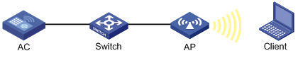
Configuration procedures
# Create service template 1.
<AC> system-view
[AC] wlan service-template 1
# Set the SSID to resource-measure, and enable service template 1.
[AC-wlan-st-1] ssid resource-measure
[AC-wlan-st-1] service-template enable
[AC-wlan-st-1] quit
# Create the manual AP ap1, and specify the AP model and serial ID.
[AC] wlan ap ap1 model WA536-WW
[AC-wlan-ap-ap1] serial-id 219801A1NQB117012935
# Enter radio view of radio 1.
[AC-wlan-ap-ap1] radio 1
# Enable spectrum management.
[AC-wlan-ap-ap1-radio-1] spectrum-management enable
# Enable radio resource measurement.
[AC-wlan-ap-ap1-radio-1] resource-measure enable
# Enable all measurement features.
[AC-wlan-ap-ap1-radio-1] measure all enable
# Set the match mode for client radio resource measurement capabilities to All.
[AC-wlan-ap-ap1-radio-1] rm-capability mode all
# Bind the service template to radio 1, and enable the radio.
[AC-wlan-ap-ap1-radio-1] service-template 1
[AC-wlan-ap-ap1-radio-1] radio enable
[AC-wlan-ap-ap1-radio-1] quit
[AC-wlan-ap-ap1] quit
Verifying the configuration
# Verify that the client has come online.
[AC] display wlan client
Total number of clients: 1
MAC address Username AP name R IP address VLAN
00ee-bd44-557f N/A ap1 1 1.1.1.1 1
# Display measurement reports from the client.
[AC] display wlan measure-report ap ap1 radio 1
Total number of clients: 1
Client MAC address : 00ee-bd44-557f
Link measurement:
Link margin : 2 dBm
RCPI : -85 dBm
RSNI : 53 dBm
Noise histogram:
Antenna ID : 3
ANPI : -56 dBm
IPI0 to IPI10 density : 5 12 16 13 8 5 5 15 17 1 3
Spectrum measurement:
Transmit power : 20 dBm
BSS : Detected
OFDM preamble : Detected
Radar : Detected
Unidentified signal : Undetected
CCA busy fraction : 60
RPI0 to RPI7 density : 3 7 11 19 15 23 15 7
Frame report entry:
BSSID : a072-2351-e253
PHY type : fhss
Average RCPI : -10 dBm
Last RSNI : 2 dBm
Last RCPI : -20 dBm
Frames : 1
Dot11BSSAverageAccessDelay group:
Average access delay : 32 ms
BestEffort average access delay : 1 ms
Background average access delay : 1 ms
Video average access delay : 1 ms
Voice average access delay : 1 ms
Clients : 32
Channel utilization rate : 11
Transmit stream:
Traffic ID : 0
Sent MSDUs : 60
Discarded MSDUs : 5
Failed MSDUs : 3
MSDUs resent multiple times : 3
Lost QoS CF-Polls : 2
Average queue delay : 2 ms
Average transmit delay : 1 ms
Bin0 range : 0 to 10 ms
Bin0 to Bin5 : 5 10 10 5 10 10
Configuring channel scanning
Overview
Channel scanning enables APs to scan channels and capture wireless packets. The AC analyzes the captured wireless packets to obtain wireless service information, including interferences, error bit rate, and wireless signal strength. Channel scanning provides data for WLAN RRM and WIPS, and enhances wireless service quality.
Basic concepts
· Scanning period—In this period, an AP only scans a channel and does not provide wireless services.
· Service period—In this period, an AP works in either of the following ways:
? The AP only provides wireless services and does not scan channels.
? The AP scans its working channel and provides wireless services simultaneously for a time period that is the same as the scanning period. After that, the AP only provides wireless services.
Work mechanism
An AP scans each channel on the channel scanning list in turn regardless of whether the AP provides wireless services, and each channel is scanned for a scanning period. If the AP does not provide wireless services, it starts scanning periods consecutively. If the AP provides wireless services, it starts service periods and scanning periods alternatively.
For example, Figure 77 shows the channel scanning mechanism for an AP when the AP works on channel 6 and the channel scanning list contains channels 1, 6, and 11.
Figure 77 Channel scanning mechanism
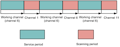
Configuring channel scanning
Setting the scanning period
Make sure the scanning period is not greater than the maximum service period.
Setting the scanning period in radio view
|
Step |
Command |
Remarks |
|
1. Enter system view. |
system-view |
N/A |
|
2. Enter AP view. |
wlan ap ap-name [ model model-name ] |
N/A |
|
3. Enter radio view. |
radio radio-id |
N/A |
|
4. Set the scanning period. |
scan scan-time scan-time |
By default, a radio uses the configuration in AP group radio view. |
Setting the scanning period in AP group radio view
|
Step |
Command |
Remarks |
|
1. Enter system view. |
system-view |
N/A |
|
2. Enter AP group view. |
wlan ap-group group-name |
N/A |
|
3. Enter AP model view. |
ap-model ap-model |
N/A |
|
4. Enter radio view. |
radio radio-id |
N/A |
|
5. Set the scanning period. |
scan scan-time scan-time |
By default, the scanning period is 100 milliseconds. |
Setting the maximum service period
To ensure both scanning and service quality, you can set the maximum service period. When the maximum service period is reached, the AP starts a scanning period regardless of whether it has traffic to forward. To ensure wireless service quality, you can configure the AP to not limit the service period. The AP does not start a scanning period unless the service idle timeout expires.
Setting the maximum service period in radio view
|
Step |
Command |
Remarks |
|
1. Enter system view. |
system-view |
N/A |
|
2. Enter AP view. |
wlan ap ap-name [ model model-name ] |
N/A |
|
3. Enter radio view. |
radio radio-id |
N/A |
|
4. Set the maximum service period. |
scan max-service-time { max-service-time | no-limit } |
By default, a radio uses the configuration in AP group radio view. |
Setting the maximum service period in AP group radio view
|
Step |
Command |
Remarks |
|
1. Enter system view. |
system-view |
N/A |
|
2. Enter AP group view. |
wlan ap-group group-name |
N/A |
|
3. Enter AP model view. |
ap-model ap-model |
N/A |
|
4. Enter radio view. |
radio radio-id |
N/A |
|
5. Set the maximum service period. |
scan max-service-time { max-service-time | no-limit } |
By default, the maximum service period is 5000 milliseconds. |
Setting the service idle timeout
During a service period, an AP does not begin a new scanning period until the current service period exceeds the scanning period even if the specified service idle timeout expires.
Setting the service idle timeout in radio view
|
Step |
Command |
Remarks |
|
1. Enter system view. |
system-view |
N/A |
|
2. Enter AP view. |
wlan ap ap-name [ model model-name ] |
N/A |
|
3. Enter radio view. |
radio radio-id |
N/A |
|
4. Set the service idle timeout. |
scan idle-time idle-time |
By default, a radio uses the configuration in AP group radio view. The service idle timeout cannot be greater than the maximum service period. |
Setting the service idle timeout timer in AP group radio view
|
Step |
Command |
Remarks |
|
1. Enter system view. |
system-view |
N/A |
|
2. Enter AP group view. |
wlan ap-group group-name |
N/A |
|
3. Enter AP model view. |
ap-model ap-model |
N/A |
|
4. Enter radio view. |
radio radio-id |
N/A |
|
5. Set the service idle timeout timer. |
scan idle-time idle-time |
By default, the service idle timeout timer is 100 milliseconds. |
Configuring the channel scanning blacklist or whitelist
Perform this task for an AP to not scan channels in the blacklist or to scan only channels in the whitelist. You cannot configure both the channel scanning blacklist and whitelist for the same AP.
Configuring the channel scanning blacklist or whitelist in radio view
|
Step |
Command |
Remarks |
|
1. Enter system view. |
system-view |
N/A |
|
2. Enter AP view. |
wlan ap ap-name [ model model-name ] |
N/A |
|
3. Enter radio view. |
radio radio-id |
N/A |
|
4. Add the specified channels to the channel scanning blacklist. |
scan channel blacklist channel-list |
By default, a radio uses the configuration in AP group radio view. |
|
5. Add the specified channels to the channel scanning whitelist. |
scan channel whitelist channel-list |
By default, a radio uses the configuration in AP group radio view. |
Configuring the channel scanning blacklist or whitelist in AP group radio view
|
Step |
Command |
Remarks |
|
1. Enter system view. |
system-view |
N/A |
|
2. Enter AP group view. |
wlan ap-group group-name |
N/A |
|
3. Enter AP model view. |
ap-model ap-model |
N/A |
|
4. Enter radio view. |
radio radio-id |
N/A |
|
5. Add the specified channels to the channel scanning blacklist. |
scan channel blacklist channel-list |
By default, no channel scanning blacklist exists. |
|
6. Add the specified channels to the channel scanning whitelist. |
scan channel whitelist channel-list |
By default, no channel scanning whitelist exists. |
Scanning all channels
This feature is restricted to Hong Kong and Macao.
|
|
IMPORTANT: This feature is applicable only to dual-band radios. |
Perform this task to enable an AP to alternatively scan 2.4 GHz channels and 5 GHz channels at the specified interval.
Scanning all channels in radio view
|
Step |
Command |
Remarks |
|
1. Enter system view. |
system-view |
N/A |
|
2. Enter AP view. |
wlan ap ap-name [ model model-name ] |
N/A |
|
3. Enter radio view. |
radio radio-id |
N/A |
|
4. Enable the radio to scan all channels. |
scan mode all [ interval interval-value ] |
By default, a radio uses the configuration in AP group radio view. |
Scanning all channels in AP group radio view
|
Step |
Command |
Remarks |
|
1. Enter system view. |
system-view |
N/A |
|
2. Enter AP group view. |
wlan ap-group group-name |
N/A |
|
3. Enter AP model view. |
ap-model ap-model |
N/A |
|
4. Enter radio view. |
radio radio-id |
N/A |
|
5. Enable the radio to scan all channels. |
scan mode all [ interval interval-value ] |
By default, a radio does not scan all channels. |
Channel scanning configuration examples
Relative forwarding preferred configuration example
Network requirements
As shown in Figure 78, configure channel scanning and set the maximum service period for AP 1 to ensure both channel scanning and wireless service quality.
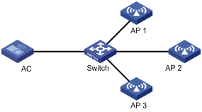
Configuration procedure
# Create a manual AP and specify the model and serial ID.
<AC> system-view
[AC] wlan ap ap1 model WA536-WW
[AC-wlan-ap-ap1] serial-id 219801A1NQB117012935
# Enter radio view of radio 1.
[AC-wlan-ap-ap1] radio 1
# Set the scanning period to 200 milliseconds.
[AC-wlan-ap-ap1-radio-1] scan scan-time 200
# Set the maximum service period to 5000 milliseconds.
[AC-wlan-ap-ap1-radio-1] scan max-service-time 5000
# Set the service idle timeout to 100 milliseconds.
[AC-wlan-ap-ap1-radio-1] scan idle-time 100
Absolute forwarding preferred configuration example
Network requirements
As shown in Figure 79, configure channel scanning and do not limit the service period for AP 1 to ensure wireless service quality.

Configuration procedure
# Create a manual AP and specify the model and serial ID.
<AC> system-view
[AC] wlan ap ap1 model WA536-WW
[AC-wlan-ap-ap1] serial-id 219801A1NQB117012935
# Enter radio view of radio 1.
[AC-wlan-ap-ap1] radio 1
# Set the scanning period to 100 milliseconds.
[AC-wlan-ap-ap1-radio-1] scan scan-time 100
# Configure the radio to not limit the service period.
[AC-wlan-ap-ap1-radio-1] scan max-service-time no-limit
# Set the service idle timeout to 100 milliseconds.
[AC-wlan-ap-ap1-radio-1] scan idle-time 100
Configuring band navigation
Overview
As shown in Figure 80, band navigation is enabled in the WLAN. Client 1 is associated with the 5 GHz radio and Client 2 is associated with the 2.4 GHz radio. When the dual-band client Client 3 requests to associate with the 2.4 GHz radio, the AP rejects Client 3 and directs it to the 5 GHz radio.
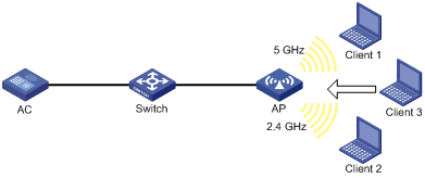
Configuration task list
|
Tasks at a glance |
|
· (Required.) Enabling band navigation globally · (Required.) Enabling band navigation for an AP · (Optional.) Configuring load balancing for band navigation · (Optional.) Configuring band navigation parameters |
Configuration prerequisites
Make sure fast association is disabled for the wireless service. For more information about fast association, see "Configuring WLAN access."
Make sure both the 5 GHz and 2.4 GHz radios are enabled and the radios are bound to the same service template.
Configuring band navigation
Do not enable band navigation in a WLAN when most clients in the WLAN support only the 2.4 GHz band or in a WLAN that is sensitive to traffic delay.
Enabling band navigation globally
|
Step |
Command |
Remarks |
|
1. Enter system view. |
system-view |
N/A |
|
2. Enable band navigation globally. |
wlan band-navigation enable |
By default, band navigation is disabled globally. |
Enabling band navigation for an AP
Band navigation takes effect on an AP only when you enable band navigation both globally and for the AP.
Enabling band navigation for an AP
|
Step |
Command |
Remarks |
|
1. Enter system view. |
system-view |
N/A |
|
2. Enter AP view. |
wlan ap ap-name [ model model-name ] |
N/A |
|
3. Enable band navigation for the AP. |
band-navigation enable |
By default, the AP uses the configuration in AP group view. |
Enabling band navigation for an AP group
|
Step |
Command |
Remarks |
|
4. Enter system view. |
system-view |
N/A |
|
5. Enter AP group view. |
wlan ap-group group-name |
N/A |
|
6. Enable band navigation for the AP group. |
band-navigation enable |
By default, band navigation is enabled. |
Configuring load balancing for band navigation
An AP rejects the 5 GHz association request of a client when the following conditions are met:
· The number of clients on the 5 GHz radio reaches the specified threshold.
· The client number gap between the 5 GHz radio and the radio that has the fewest clients reaches the specified threshold.
To enable load balancing for band navigation:
|
Step |
Command |
Remarks |
|
1. Enter system view. |
system-view |
N/A |
|
2. Configure load balancing for band navigation. |
wlan band-navigation balance session session [ gap gap ] |
By default, load balancing is disabled for band navigation. |
Configuring band navigation parameters
The following parameters affect band navigation:
· Maximum number of denials for 5 GHz association requests—If the number of times that a 5 GHz radio rejects a client reaches the specified maximum number, the radio accepts the association request of the client.
· Band navigation RSSI threshold—A client might be detected by multiple radios. A 5 GHz radio rejects the association request of a client if the client's RSSI is lower than the band navigation RSSI threshold.
· Client information aging time—When an AP receives an association request from a client, the AP records the client's information and starts the client information aging timer. If the AP does not receive any probe requests or association requests from the client before the aging timer expires, the AP deletes the client's information.
Configure appropriate client information aging time to ensure both client association and system resource efficiency.
To configure band navigation parameters:
|
Step |
Command |
Remarks |
|
1. Enter system view. |
system-view |
N/A |
|
2. Set the maximum number of denials for 5 GHz association requests. |
wlan band-navigation balance access-denial access-denial |
By default, the AP does not reject 5 GHz association requests. |
|
3. Set the band navigation RSSI threshold. |
wlan band-navigation rssi-threshold rssi-threshold |
By default, the band navigation RSSI threshold is 15. |
|
4. Set the client information aging time. |
wlan band-navigation aging-time aging-time |
By default, the client information aging time is 180 seconds. |
Band navigation configuration examples
Network requirements
As shown in Figure 81, both the 5 GHz radio and the 2.4 GHz radio are enabled on the AP. Configure band navigation and load balancing for band navigation to load balance the radios.
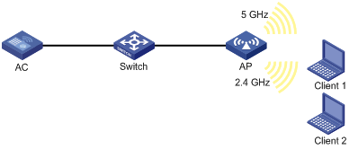
Configuration procedure
# Create service template 1 and set its SSID to band-navigation.
<AC> system-view
[AC] wlan service-template 1
[AC-wlan-st-1] ssid band-navigation
[AC-wlan-st-1] service-template enable
[AC-wlan-st-1] quit
# Create the AP template ap1, and specify the model and serial ID.
[AC] wlan ap ap1 model WA536-WW
[AC-wlan-ap-ap1] serial-id 219801A1NQB117012935
# Enter radio view of radio 1, and configure radio 1 to operate in 802.11n (5 GHz) mode.
[AC-wlan-ap-ap1] radio 1
[AC-wlan-ap-ap1-radio-1] type dot11an
# Bind service template 1 to radio 1 of AP 1, and enable radio 1.
[AC-wlan-ap-ap1-radio-1] service-template 1
[AC-wlan-ap-ap1-radio-1] radio enable
[AC-wlan-ap-ap1-radio-1] quit
# Enter radio view of radio 2, and configure radio 2 to operate in 802.11n (2.4 GHz) mode.
[AC-wlan-ap-ap1] radio 2
[AC-wlan-ap-ap1-radio-2] type dot11gn
# Bind service template 1 to radio 2 of AP 1, and enable radio 2.
[AC-wlan-ap-ap1-radio-2] service-template 1
[AC-wlan-ap-ap1-radio-2] radio enable
[AC-wlan-ap-ap1-radio-2] quit
[AC-wlan-ap-ap1] quit
# Enable band navigation globally.
[AC] wlan band-navigation enable
# Enable band navigation for AP 1.
[AC] wlan ap ap1 model WA536-WW
[AC-wlan-ap-ap1] band-navigation enable
[AC-wlan-ap-ap1] quit
# Enable load balancing for band navigation, and set the client number threshold and client number gap threshold to 5 and 2, respectively.
[AC] wlan band-navigation balance session 5 gap 2
# Set the maximum number of denials for 5 GHz association requests to 3.
[AC] wlan band-navigation balance access-denial 3
# Set the band navigation RSSI threshold to 30.
[AC] wlan band-navigation rssi-threshold 30
# Set the client information aging time to 160 seconds.
[AC] wlan band-navigation aging-time 160
Verifying the configuration
1. Verify that a dual-band client is associated with the 5 GHz radio when it requests to associate with the AP. (Details not shown.)
2. Verify that a dual-band client is associated with the 2.4 GHz radio when the following conditions are met:
? The number of clients on the 5 GHz radio reaches 5.
? The client number gap between the 5 GHz radio and the 2.4 GHz radio reaches 2. (Details not shown.)
Configuring dual-link backup
Overview
Dual-link backup enables two ACs to back up each other. This reduces risks of service interruption caused by single-AC failures.
With dual-link backup enabled, an AP establishes a master tunnel and a backup CAPWAP tunnel with the master AC and the backup AC, respectively. The master and backup ACs cannot detect each other's link state in real time. When the backup AC takes over traffic forwarding upon master AC failure, temporary communication interruption occurs. When the failed master AC recovers, the master CAPWAP tunnel preemption feature determines the master CAPWAP tunnel based on the AP connection priority.
Dual-link backup is applicable to networks that are service continuity insensitive.
Figure 82 Network diagram for dual-link backup
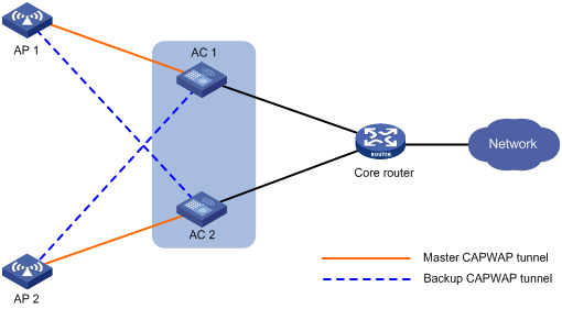
Dual-link backup configuration task list
|
Tasks at a glance |
|
(Required.) Setting AP connection priority and specifying a backup AC |
|
(Optional.) Configuring master CAPWAP tunnel preemption |
Configuration prerequisites
Configure auto AP or manual APs on both ACs. The manual AP configuration must be identical on the two ACs. For more information, see "Managing APs."
Setting AP connection priority and specifying a backup AC
After an AP establishes a CAPWAP tunnel with the master AC, the AP will establish a backup CAPWAP tunnel with the specified backup AC.
As a best practice, set a higher AP connection priority for the master AC to ensure that APs can associate with the master AC first.
Specifying a backup AC for an AP
|
Step |
Command |
Remarks |
|
1. Enter system view. |
system-view |
N/A |
|
2. Enter AP view. |
wlan ap ap-name |
N/A |
|
3. Set the AP connection priority. |
priority priority |
By default, an AP uses the configuration in AP group view. |
|
4. Specify a backup AC. |
backup-ac { ip ipv4-address | ipv6 ipv6-address } |
By default, an AP uses the configuration in AP group view. |
Specifying a backup AC for an AP group
|
Step |
Command |
Remarks |
|
1. Enter system view. |
system-view |
N/A |
|
2. Enter AP group view. |
wlan ap-group groupname |
N/A |
|
3. Set the AP connection priority. |
priority priority |
By default, the AP connection priority is 4. |
|
4. Specify a backup AC. |
backup-ac { ip ipv4-address | ipv6 ipv6-address } |
By default, no backup AC is specified. |
Configuring master CAPWAP tunnel preemption
This feature enables a backup CAPWAP tunnel to become a master tunnel if the backup AC has higher AP connection priority than the master AC.
Configuring master CAPWAP tunnel preemption for an AP
|
Step |
Command |
Remarks |
|
1. Enter system view. |
system-view |
N/A |
|
2. Enter AP view. |
wlan ap ap-name |
N/A |
|
3. Configure master CAPWAP tunnel preemption. |
wlan tunnel-preempt { disable | enable } |
By default, an AP uses the configuration in AP group view. |
Configuring master CAPWAP tunnel preemption for an AP group
|
Step |
Command |
Remarks |
|
1. Enter system view. |
system-view |
N/A |
|
2. Enter AP group view. |
wlan ap-group groupname |
N/A |
|
3. Configure master CAPWAP tunnel preemption. |
wlan tunnel-preempt { disable | enable } |
By default, an AP uses the configuration in global configuration view. |
Configuring master CAPWAP tunnel preemption globally
|
Step |
Command |
Remarks |
|
1. Enter system view. |
system-view |
N/A |
|
2. Enter global configuration view. |
wlan global-configuration |
N/A |
|
3. Configure master CAPWAP tunnel preemption. |
wlan tunnel-preempt { disable | enable } |
By default, master CAPWAP tunnel preemption is disabled. |
Dual-link backup configuration example
Network requirements
As shown in Figure 83, configure AC 1 to act as the master AC and AC 2 as the backup AC. When AC 1 fails and AC 2 takes over, the AP can communicate through AC 2. Configure the master CAPWAP tunnel preemption feature on both ACs so that the AP reconnects to AC 1 when AC 1 recovers.
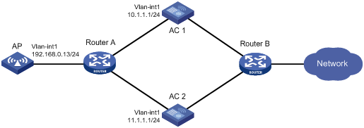
Configuration procedure
1. Configure AC 1:
# Create VLAN-interface 1 and assign an IP address to it.
<AC1> system-view
[AC1] interface vlan-interface 1
[AC1-Vlan-interface1] ip address 10.1.1.1 24
[AC1-Vlan-interface1] quit
# Create an AP named ap1, and specify the AP model and serial ID. Set the AP connection priority to 7.
[AC1] wlan ap ap1 model WA536-WW
[AC1-wlan-ap-ap1] serial-id 219801A1NQB117012935
[AC1-wlan-ap-ap1] priority 7
# Specify an IPv4 backup AC.
[AC1-wlan-ap-ap1] backup-ac ip 11.1.1.1
# Enable master CAPWAP tunnel preemption.
[AC1-wlan-ap-ap1] wlan tunnel-preempt enable
[AC1-wlan-ap-ap1] quit
2. Configure AC 2:
# Create VLAN-interface 1 and assign an IP address to it.
<AC2> system-view
[AC2] interface Vlan-interface 1
[AC2-Vlan-interface1] ip address 11.1.1.1 24
[AC2-Vlan-interface1] quit
# Create an AP named ap1, and specify the AP model and serial ID. Set the AP connection priority to 5.
[AC2] wlan ap ap1 model WA536-WW
[AC2-wlan-ap-ap1] serial-id 219801A1NQB117012935
[AC2-wlan-ap-ap1] priority 5
# Specify an IPv4 backup AC.
[AC2-wlan-ap-ap1] backup-ac ip 10.1.1.1
# Enable master CAPWAP tunnel preemption.
[AC2-wlan-ap-ap1] wlan tunnel-preempt enable
[AC2-wlan-ap-ap1] quit
Verifying the configuration
# Get the AP online on AC 1. (Details not shown.)
# Shut down VLAN-interface 1 on AC 1 and wait no longer than 3 minutes, during which service interruption occurs. (Details not shown.)
# Verify that the AP comes online on AC 2 and the AP state is R/M on AC 2. (Details not shown.)
# Bring up VLAN-interface 1 on AC 1. (Details not shown.)
# Verify that the AP comes online on AC 1 again and the AP state is R/M on AC 1 and R/B on AC 2. (Details not shown.)
Configuring AP load balancing
Overview
AP load balancing (LB) enables multiple ACs to form an IRF fabric to ensure centralized AP management and avoid wireless service interruption in case of AC failures.
AC roles
An AC has the following roles:
|
Role |
Description |
|
Master AC |
Master in an IRF fabric. A master AC performs the following tasks: · Manages the entire IRF fabric. · Load balances APs among active ACs according to an LB algorithm. · Maintains an AP LB table that records the CAPWAP tunnel establishment relationships between APs and active ACs, and synchronizes the table among all ACs in the fabric. |
|
Subordinate AC |
Subordinate in an IRF fabric. A subordinate AC processes services, forwards packets, and acts as a backup for the master AC. When the master AC fails, the system automatically elects a new master AC from the subordinate ACs in the IRF fabric. |
|
Active AC |
An AC that can establish CAPWAP tunnels with APs and load balance APs with other active ACs. The master AC is always an active AC. It selects a specific number of active ACs from the subordinate ACs. |
|
Non-active AC |
An AC that cannot establish CAPWAP tunnels with APs. Non-active ACs can only be subordinate ACs. When an active AC fails, a non-active AC will be elected as an active AC. |
|
Directly connected AC |
An AC that receives the first packet from an AP when the AP launches a CAPWAP tunnel establishment process. |
AP load balancing
After multiple ACs form an IRF fabric, the IRF fabric appears as one AC to APs. When the IRF fabric receives a CAPWAP tunnel establishment request, the master AC uses an LB algorithm to select an AC from the active ACs for tunnel establishment. Figure 84 shows the LB algorithm.
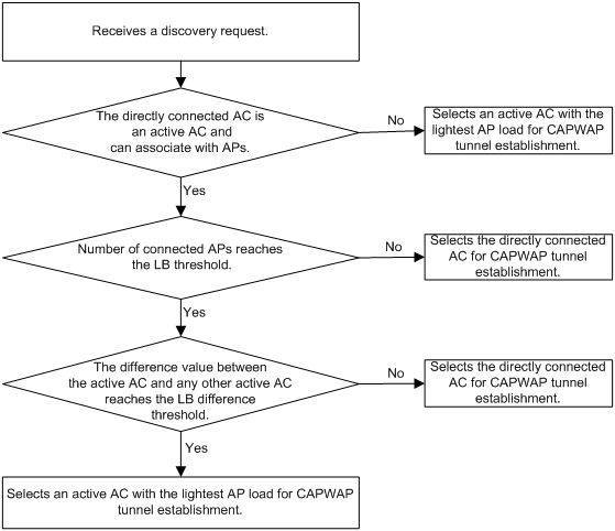
As shown in Figure 85, AC 1, AC 2, and AC 3 form an IRF fabric. AC 1 is the master AC and also an active AC. AC 2 is an active AC and also a directly connected AC to AP 1. AC 3 is a non-active AC. AP 1 establishes a CAPWAP tunnel with the IRF fabric by using the following process:
1. The AP sends a discovery request.
2. Upon receiving the discovery request, AC 2 notifies AC 1.
3. AC 1 determines whether a CAPWAP tunnel can be established with the AP, and then selects AC 1, for example, for CAPWAP tunnel establishment by using the LB algorithm.
4. AC 1 records the CAPWAP tunnel establishment relationship between the AP and AC 1 in the AP LB table and synchronizes the table to all ACs in the IRF fabric.
5. After receiving the AP LB table, AC 2 sends a discovery response to the AP.
6. After receiving the discovery response, the AP sends a join request to the IRF fabric.
7. The AC that receives the join request examines the AP LB table and learns that it is AC 1 that will establish a CAPWAP tunnel with the AP. Then, the AC forwards the join request to AC 1.
8. After receiving the join request, AC 1 sends a join response to the AP.
Figure 85 AP load balancing
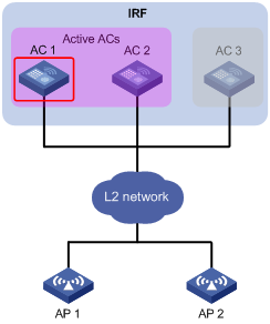
Feature and hardware compatibility
|
Hardware series |
Model |
AP load balancing compatibility |
|
WX1800H series |
WX1804H WX1810H WX1820H WX1840H |
No |
|
WX3800H series |
WX3820H WX3840H |
Yes |
|
WX5800H |
WX5860H |
Yes |
Configuration prerequisites
Before configuring AP load balancing, set up an IRF fabric for the target ACs. For information about IRF, see Virtual Technologies Configuration Guide.
Setting the number of active ACs
After you set the number of active ACs, the master AC will select an active AC among the non-active ACs according to the order in which they are saved to the AC information table. An AC has higher priority if its information is saved earlier.
When an active AC fails, the master AC randomly selects a new active AC from non-active ACs.
To set the number of active ACs:
|
Step |
Command |
Remarks |
|
1. Enter system view. |
system-view |
N/A |
|
2. Set the number of active ACs. |
wlan ap-backup active count number |
By default, the number of active ACs is 1. Only the master AC can act as an active AC to establish CAPWAP tunnels with APs. |
Setting the threshold and gap threshold for AP load balancing
The threshold and gap threshold are used in the LB algorithm to implement AP load balancing among active ACs in an IRF fabric. For information about the LB algorithm, see "AP load balancing."
To set the threshold and gap threshold for AP load balancing:
|
Step |
Command |
Remarks |
|
1. Enter system view. |
system-view |
N/A |
|
2. Set the threshold and gap threshold for AP load balancing. |
wlan ap-backup load-balance threshold threshold-value gap gap-value |
The following default setting applies: · The AP load-balancing threshold is the maximum number of APs supported by the current AC. · The gap threshold is a quarter of APs associated with the directly connected AC. |
Displaying and maintaining AP load balancing
Execute display commands in any view.
|
Task |
Command |
|
Display AP LB status for all IRF member ACs. |
display wlan ap backup multislot |
AP load balancing configuration example
Network requirements
As shown in Figure 86, AC 1 and AC 2 form an IRF fabric. To implement central management of APs, configure both ACs as active ACs.
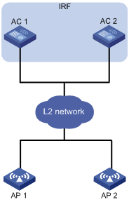
Configuration procedure
# Set up an IRF fabric. (Details not shown.)
For more information, see Virtual Technologies Configuration Guide.
# Set the number of active ACs to 2.
<AC> system-view
[AC] wlan ap-backup active count 2
Verifying the configuration
# Verify that both ACs can establish CAPWAP tunnels with APs and back up AP information for each other.
<AC> display wlan ap backup multislot
Borad Status
Total number of slots: 2
Slot ID State
1 active-only
2 active-only
Configuring WLAN uplink detection
Overview
When the uplink of an AC fails, clients cannot access external networks through the APs that are connected to the AC. WLAN uplink detection associates the uplink state of an AC with the radio state of the connected APs. When the uplink fails, the AC disables the radios of the APs. When the uplink recovers, the AC enables the radios of the APs. The association ensures that clients can associate with APs connected to another AC when the uplink of an AC fails.
This feature collaborates with a detection module and the Track module to function.
· When the track entry is in Positive state, the AC enables the radios of the connected APs.
· When the track entry is in Negative state, the AC disables the radios of the connected APs.
· When the track entry is in Invalid state, the AC does not change the radio state of the connected APs.
For more information about the track module, see High Availability Configuration Guide.
Associating a track entry with the WLAN uplink detection feature
|
Step |
Command |
Remarks |
|
1. Enter system view. |
system-view |
N/A |
|
2. Configure a detection module to detect the uplink state, and associate a track entry with the detection module. |
For information about Track association with detection modules, see High Availability Configuration Guide. |
N/A |
|
3. Associate the track entry with the WLAN uplink detection feature. |
wlan uplink track track-entry-number |
By default, WLAN uplink detection is not associated with any track entry. |
WLAN uplink detection configuration example
Network requirements
As shown in Figure 87, use an NQA operation to test the accessibility of each AC's uplink. Configure WLAN uplink detection on each AC, so that when the uplink of an AC fails, clients can associate with the AP connected to another AC that operates correctly.
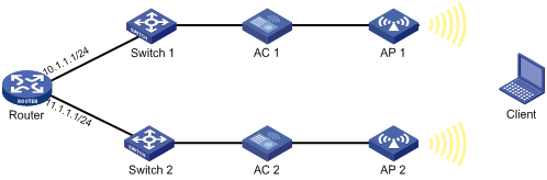
Configuration procedure
1. Configure AC 1:
# Create an ICMP echo operation.
<AC1> system-view
[AC1] nqa entry admin test
[AC1-nqa-admin-test] type icmp-echo
# Specify 10.1.1.1 as the destination IP address of ICMP echo requests.
[AC1-nqa-admin-test-icmp-echo] destination ip 10.1.1.1
# Create reaction entry 1. If the number of consecutive probe failures reaches 5, collaboration is triggered.
[AC1-nqa-admin-test-icmp-echo] reaction 1 checked-element probe-fail threshold-type consecutive 5 action-type trigger-only
[AC1-nqa-admin-test-icmp-echo] quit
# Start the ICMP echo operation.
[AC1] nqa schedule admin test start-time now lifetime forever
# Configure track entry 1, and associate it with reaction entry 1 of the NQA operation (with administrator admin, and operation tag test).
[AC1] track 1 nqa entry admin test reaction 1
# Associate track entry 1 with WLAN uplink detection.
[AC1] wlan uplink track 1
[AC1] quit
2. Configure AC 2:
# Create an ICMP echo operation.
<AC2> system-view
[AC2] nqa entry admin test
[AC2-nqa-admin-test] type icmp-echo
# Specify 11.1.1.1 as the destination IP address of ICMP echo requests.
[AC2-nqa-admin-test-icmp-echo] destination ip 11.1.1.1
# Create reaction entry 1. If the number of consecutive probe failures reaches 5, collaboration is triggered.
[AC2-nqa-admin-test-icmp-echo] reaction 1 checked-element probe-fail threshold-type consecutive 5 action-type trigger-only
[AC2-nqa-admin-test-icmp-echo] quit
# Start the ICMP echo operation.
[AC2] nqa schedule admin test start-time now lifetime forever
# Configure track entry 1, and associate it with reaction entry 1 of the NQA operation (with administrator admin, and operation tag test).
[AC2] track 1 nqa entry admin test reaction 1
# Associate track entry 1 with WLAN uplink detection.
[AC2] wlan uplink track 1
[AC2] quit
Verifying the configuration
This example uses AC 1 to verify the configuration.
1. Verify that the radio of AP 1 is in Up state when the state of track entry 1 is Positive:
# Display information about track entry 1.
<AC1> display track 1
Track ID: 1
State: Positive
Duration: 0 days 1 hours 5 minutes 48 seconds
Notification delay: Positive 0, Negative 0 (in seconds)
Tracked object:
NQA entry: admin test
Reaction: 1
# Display detailed information about AP ap1.
<AC1> display wlan ap name ap1 verbose
AP name : ap1
AP ID : 1
AP group name : default-group
State : Run
Online time : 0 days 2 hours 25 minutes 12 seconds
System up time : 0 days 1 hours 22 minutes 12 seconds
Model : WA536-WW
Region code : US
Region code lock : Disable
Serial ID : 219801A1NQB117012935
MAC address : 83D5-AB43-67FF
IP address : 1.1.1.2
H/W version : Ver.C
S/W version : V700R001B62D001
Boot version : 1.01
Description : wtp1
Priority : 4
Echo interval : 10 seconds
Statistics report interval : 50 seconds
Jumbo frame value : Disabled
MAC type : Local MAC & Split MAC
Tunnel mode : Local Bridging & 802.3 Frame & Native Frame
Discovery type : DHCP
Retransmission count : 3
Retransmission interval : 5 seconds
Firmware upgrade : Enabled
Sent control packets : 1
Received control packets : 1
Connection count : 1
Backup Ipv4 : Not configured
Backup Ipv6 : Not configured
Tunnel encryption : Disabled
LED mode : Normal
Radio 1:
Basic BSSID : N/A
Admin state : Up
Radio type : 802.11n(5GHz)
Antenna type : internal
Client dot11ac-only : Disabled
Client dot11n-only : Disabled
Channel band-width : 20/40MHz
Secondary channel offset : SCB
Short GI for 20MHz : Supported
Short GI for 40MHz : Supported
A-MSDU : Enabled
A-MPDU : Enabled
LDPC : Not Supported
STBC : Supported
Operational HT MCS Set:
Mandatory : Not configured
Supported : 0, 1, 2, 3, 4, 5, 6, 7, 8, 9,
10, 11, 12, 13, 14, 15
Multicast : Not configured
Channel : 64(auto)
Max power : 13 dBm
Operational rate:
Mandatory : 6, 12, 24 Mbps
Supported : 9, 18, 36, 48, 54 Mbps
Multicast : 24 Mbps
Disabled : Not configured
Distance : 1 km
ANI : Enabled
Fragmentation threshold : 2346 bytes
Beacon interval : 100 TU
Protection threshold : 2346 bytes
Long retry threshold : 4
Short retry threshold : 7
Maximum rx duration : 2000 ms
Noise Floor : 0 dBm
Smart antenna : Enabled
Smart antenna policy : Auto
Radio 2:
Basic BSSID : N/A
Admin state : Up
Radio type : 802.11b
Antenna type : internal
Channel : 5(auto)
Max power : 20 dBm
Preamble type : Short
Operational rate:
Mandatory : 1, 2 Mbps
Multicast : Auto
Supported : 5.5, 11 Mbps
Disabled : Not configured
Distance : 1 km
ANI : Enabled
Fragmentation threshold : 2346 bytes
Beacon interval : 100 TU
Protection threshold : 2346 bytes
Long retry threshold : 4
Short retry threshold : 7
Maximum rx duration : 2000 ms
Noise Floor : 0 dBm
2. Verify that the radio of AP 1 is in Down state when the state of track entry 1 is Negative:
# Display information about track entry 1.
<AC1> display track 1
Track ID: 1
State: Negative
Duration: 0 days 2 hours 5 minutes 48 seconds
Notification delay: Positive 0, Negative 0 (in seconds)
Tracked object:
NQA entry: admin test
Reaction: 1
# Display detailed information about AP ap1.
<AC1> display wlan ap name ap1 verbose
AP name : ap1
AP ID : 1
AP group name : default-group
State : Run
Online time : 0 days 3 hours 25 minutes 12 seconds
System up time : 0 days 2 hours 22 minutes 12 seconds
Model : WA536-WW
Region code : US
Region code lock : Disable
Serial ID : 219801A1NQB117012935
MAC address : 83D5-AB43-67FF
IP address : 1.1.1.2
H/W version : Ver.C
S/W version : V700R001B62D001
Boot version : 1.01
Description : wtp1
Priority : 4
Echo interval : 10 seconds
Statistics report interval : 50 seconds
Jumbo frame value : Disabled
MAC type : Local MAC & Split MAC
Tunnel mode : Local Bridging & 802.3 Frame & Native Frame
Discovery type : DHCP
Retransmission count : 3
Retransmission interval : 5 seconds
Firmware upgrade : Enabled
Sent control packets : 1
Received control packets : 1
Connection count : 1
Backup Ipv4 : Not configured
Backup Ipv6 : Not configured
Tunnel encryption : Disabled
LED mode : Normal
Radio 1:
Basic BSSID : N/A
Admin state : Down
Radio type : 802.11n(5GHz)
Antenna type : internal
Client dot11ac-only : Disabled
Client dot11n-only : Disabled
Channel band-width : 20/40MHz
Secondary channel offset : SCB
Short GI for 20MHz : Supported
Short GI for 40MHz : Supported
A-MSDU : Enabled
A-MPDU : Enabled
LDPC : Not Supported
STBC : Supported
Operational HT MCS Set:
Mandatory : Not configured
Supported : 0, 1, 2, 3, 4, 5, 6, 7, 8, 9,
10, 11, 12, 13, 14, 15
Multicast : Not configured
Channel : 64(auto)
Max power : 13 dBm
Operational rate:
Mandatory : 6, 12, 24 Mbps
Supported : 9, 18, 36, 48, 54 Mbps
Multicast : 24 Mbps
Disabled : Not configured
Distance : 1 km
ANI : Enabled
Fragmentation threshold : 2346 bytes
Beacon interval : 100 TU
Protection threshold : 2346 bytes
Long retry threshold : 4
Short retry threshold : 7
Maximum rx duration : 2000 ms
Noise Floor : 0 dBm
Smart antenna : Enabled
Smart antenna policy : Auto
Radio 2:
Basic BSSID : N/A
Admin state : Down
Radio type : 802.11b
Antenna type : internal
Channel : 5(auto)
Max power : 20 dBm
Preamble type : Short
Operational rate:
Mandatory : 1, 2 Mbps
Multicast : Auto
Supported : 5.5, 11 Mbps
Disabled : Not configured
Distance : 1 km
ANI : Enabled
Fragmentation threshold : 2346 bytes
Beacon interval : 100 TU
Protection threshold : 2346 bytes
Long retry threshold : 4
Short retry threshold : 7
Maximum rx duration : 2000 ms
Noise Floor : 0 dBm
Configuring 802.11r
This chapter describes how to configure 802.11r.
802.11r overview
802.11r fast BSS transition (FT) minimizes the delay when a client roams from a BSS to another BSS within the same ESS. During 802.11r FT, a client needs to exchange messages with the target AP. FT provides the following message exchanging methods:
· Over-the-air—The client communicates directly with the target AP for pre-roaming authentication.
· Over-the-DS—The client communicates with the target AP through the current AP for pre-roaming authentication.
802.11r operating mechanism
Intra-AC roaming through over-the-air FT
As shown in Figure 88, the client is associated with AP 1. Intra-AC roaming through over-the-air FT uses the following procedure:
1. The client sends an FT authentication request to AP 2.
2. AP 2 sends an FT authentication response to the client.
3. The client sends a reassociation request to AP 2.
4. AP 2 sends a reassociation response to the client.
5. The client roams to AP 2.
Figure 88 Intra-AC roaming through over-the-air FT
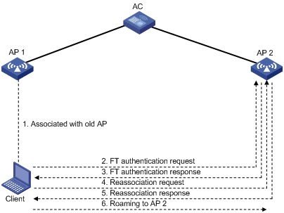
Inter-AC roaming through over-the-air FT
As shown in Figure 89, the client is associated with AP 1. Inter-AC roaming through over-the-air FT uses the following procedure:
1. After the client comes online, AC 1 sends roaming information for the client to AC 2. Roaming information includes the PMK and the client VLAN.
2. The client sends an FT authentication request to AP 2.
3. AP 2 sends an FT authentication response to the client.
4. The client sends a reassociation request to AP 2.
5. AP 2 sends a reassociation response to the client.
6. The client roams to AP 2.
Figure 89 Inter-AC roaming through over-the-air FT
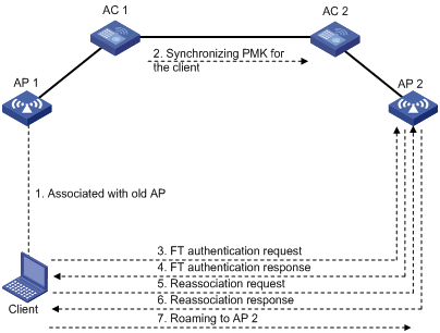
Intra-AC roaming through over-the-DS FT
As shown in Figure 90, the client is associated with AP 1. Intra-AC roaming through over-the-DS FT uses the following procedure:
1. After the client comes online, the AC creates a roaming entry and saves it for the client.
2. The client sends an FT authentication request to AP 1.
3. AP 1 sends an FT authentication response to the client.
4. The client sends a reassociation request to AP 2.
5. AP 2 sends a reassociation response to the client.
6. The client roams to AP 2.
Figure 90 Intra-AC roaming through over-the-DS FT
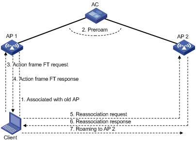
Protocols and standards
Configuring 802.11r
Follow these restrictions and guidelines when you configure 802.11r:
· To enable a client that does not support FT to access the WLAN, create two service templates using the same SSID, with one enabled with FT and the other not.
· To prevent a client from coming online every time the periodic reauthentication timer expires, do not enable FT and periodic reauthentication for the same service template. For more information about periodic reauthentication, see "Configuring WLAN authentication."
· PTK updates are not supported for clients that have been associated with a WLAN through FT. For more information about PTK updates, see "Configuring WLAN security."
To configure 802.11r:
|
Step |
Command |
Remarks |
|
1. Enter system view. |
system-view |
N/A |
|
2. Enter service template view. |
N/A |
|
|
3. Enable FT. |
ft enable |
By default, FT is disabled. |
|
4. (Optional.) Set the FT method. |
By default, the FT method is over-the-air. |
|
|
5. (Optional.) Set the reassociation timeout timer. |
By default, the association timeout timer is 20 seconds. The roaming process is terminated if a client does not send any reassociation requests before the timeout timer expires. |
802.11r configuration examples
Over-the-DS FT and PSK authentication configuration example
Network requirements
As shown in Figure 91, configure intra-AC roaming through over-the-DS FT to enable the client to roam between AP 1 and AP 2. Configure PSK as the authentication and key management mode.
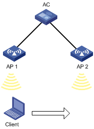
Configuration procedures
# Create the service template acstname.
[AC] wlan service-template acstname
# Set the SSID to service.
[AC-wlan-st-acstname] ssid service
# Set the authentication and key management mode to PSK, and configure the simple string 12345678 as the PSK.
[AC-wlan-st-acstname] akm mode psk
[AC-wlan-st-acstname] preshared-key pass-phrase simple 12345678
# Set the CCMP cipher suite and enable the RSN IE in the beacon and probe responses.
[AC-wlan-st-acstname] cipher-suite ccmp
[AC-wlan-st-acstname] security-ie rsn
[AC-wlan-st-acstname] ft enable
# Set the reassociation timeout timer to 50 seconds.
[AC-wlan-st-acstname] ft reassociation-timeout 50
# Set the FT method to over-the-DS.
[AC-wlan-st-acstname] ft method over-the-ds
# Enable the service template.
[AC-wlan-st-acstname] service-template enable
[AC-wlan-st-acstname] quit
# Create AP 1, and bind the service template acstname to radio 2 of the AP.
[AC] wlan ap 1
[AC-wlan-ap-1] radio 2
[AC-wlan-ap-1-radio-2] service-template acstname
[AC-wlan-ap-1-radio-2] radio enable
[AC-wlan-ap-1-radio-2] quit
# Create AP 2, and bind the service template acstname to radio 2 of the AP.
[AC] wlan ap 2
[AC-wlan-ap-2] radio 2
[AC-wlan-ap-2-radio-2] service-template acstname
[AC-wlan-ap-2-radio-2] radio enable
[AC-wlan-ap-2-radio-2] quit
[AC-wlan-ap-2] quit
Verifying the configuration
# Verify that the service template is correctly configured.
[AC] display wlan service-template acstname verbose
Service template name : acstname
SSID : service
SSID-hide : Disabled
User-isolation : Disabled
Service template status : Enabled
Maximum clients per BSS : Not configured
Frame format : Dot3
Seamless-roam : Disabled
Seamless-roam RSSI threshold : 50
Seamless-roam RSSI gap : 20
VLAN ID : 1
AKM mode : PSK
Security IE : RSN
Cipher suite : CCMP
TKIP countermeasure time : 0 sec
PTK lifetime : 43200 sec
GTK rekey : Enabled
GTK rekey method : Time-based
GTK rekey time : 86400 sec
GTK rekey client-offline : Disabled
User authentication mode : Bypass
Intrusion protection : Disabled
Intrusion protection mode : Temporary-block
Temporary block time : 180 sec
Temporary service stop time : 20 sec
Fail VLAN ID : Not configured
802.1X handshake : Disabled
802.1X handshake secure : Disabled
802.1X domain : Not configured
MAC-auth domain : Not configured
Max 802.1X users : 4096
Max MAC-auth users : 4096
802.1X re-authenticate : Disabled
Authorization fail mode : Online
Accounting fail mode : Online
Authorization : Permitted
Key derivation : SHA1
PMF status : Disabled
Hotspot policy number : Not configured
Forward policy : Not configured
Forwarder : AC
FT Status : Enable
FT Method : over-the-ds
FT Reassociation Deadline : 50 sec
QoS trust : Port
QoS priority : 0
# Verify that the roaming status is N/A and the FT status is Active.
[AC] display wlan client verbose
Total number of clients: 1
MAC address : fc25-3f03-8361
IPv4 address : 10.1.1.114
IPv6 address : N/A
Username : N/A
AID : 1
AP ID : 1
AP name : 1
Radio ID : 2
SSID : service
BSSID : 000f-e266-7788
VLAN ID : 1
Power save mode : Active
Wireless mode : 802.11gn
Channel bandwidth : 20MHz
SM power save : Enabled
SM power save mode : Static
Short GI for 20MHz : Not supported
Short GI for 40MHz : Not supported
STBC RX capability : Supported
STBC TX capability : Not supported
Support HT-MCS set : 0, 1, 2, 3, 4, 5, 6, 7
QoS mode : WMM
Listen interval : 20
RSSI : 0
Rx/Tx rate : 65/65
Authentication method : Open system
Security mode : RSN
AKM mode : PSK
Encryption cipher : CCMP
User authentication mode : Bypass
Authorization ACL ID : N/A
Authorization user profile : N/A
Roam status : N/A
Key derivation : SHA256
PMF status : N/A
Forward policy : N/A
Online time : 0hr 0min 41sec
FT status : Active
# Moves the client to the coverage of AP 2. (Details not shown.)
# Verify that the authentication method is FT and the roaming status is Intra-AC roam.
[AC] display wlan client verbose
Total number of clients: 1
MAC address : fc25-3f03-8361
IPv4 address : 10.1.1.114
IPv6 address : N/A
Username : N/A
AID : 1
AP ID : 2
AP name : 2
Radio ID : 2
SSID : service
BSSID : 000f-e211-2233
VLAN ID : 1
Power save mode : Active
Wireless mode : 802.11gn
Channel bandwidth : 20MHz
SM power save : Enabled
SM power save mode : Static
Short GI for 20MHz : Not supported
Short GI for 40MHz : Not supported
STBC RX capability : Supported
STBC TX capability : Not supported
Support HT-MCS set : 0, 1, 2, 3, 4, 5, 6, 7
QoS mode : WMM
Listen interval : 20
RSSI : 0
Rx/Tx rate : 0/0
Authentication method : FT
Security mode : RSN
AKM mode : PSK
Encryption cipher : CCMP
User authentication mode : Bypass
Authorization ACL ID : N/A
Authorization user profile : N/A
Roam status : Intra-AC roam
Key derivation : SHA256
PMF status : N/A
Forward policy : N/A
Online time : 0hr 0min 27sec
FT status : Active
Over-the-air FT and PSK authentication configuration example
Network requirements
As shown in Figure 91, configure intra-AC roaming through over-the-air FT to enable the client to roam between AP 1 and AP 2. Configure PSK as the authentication and key management mode.
Configuration procedures
# Create the service template acstname.
<AC> system-view
[AC] wlan service-template acstname
[AC-wlan-st-acstname] ssid service
# Set the authentication and key management mode to PSK, and configure the simple string 12345678 as the PSK.
[AC-wlan-st-acstname] akm mode psk
[AC-wlan-st-acstname] preshared-key pass-phrase simple 12345678
# Enable the RSN IE in the beacon and probe responses.
[AC-wlan-st-acstname] cipher-suite ccmp
[AC-wlan-st-acstname] security-ie rsn
[AC-wlan-st-acstname] ft enable
# Set the reassociation timeout to 50 seconds.
[AC-wlan-st-acstname] ft reassociation-timeout 50
# Enable the service template.
[AC-wlan-st-acstname] service-template enable
[AC-wlan-st-acstname] quit
# Create AP 1, and bind the service template acstname to radio 2 of the AP.
[AC] wlan ap 1
[AC-wlan-ap-1] radio 2
[AC-wlan-ap-1-radio-2] service-template acstname
[AC-wlan-ap-1-radio-2] radio enable
[AC-wlan-ap-1-radio-2] quit
# Create AP 2, and bind the service template acstname to radio 2 of the AP.
[AC] wlan ap 2
[AC-wlan-ap-2] radio 2
[AC-wlan-ap-2-radio-2] service-template acstname
[AC-wlan-ap-2-radio-2] radio enable
[AC-wlan-ap-2-radio-2] quit
[AC-wlan-ap-2] quit
Verifying the configuration
# Verify the following information:
· RSN IE is enabled.
· The AKM mode is PSK.
· The cipher suite is CCMP.
· The FT status is Active.
[AC] display wlan client verbose
Total number of clients: 1
MAC address : fc25-3f03-8361
IPv4 address : 10.1.1.114
IPv6 address : N/A
Username : N/A
AID : 1
AP ID : 1
AP name : 1
Radio ID : 2
SSID : service
BSSID : 000f-e266-7788
VLAN ID : 1
Power save mode : Active
Wireless mode : 802.11gn
Channel bandwidth : 20MHz
SM power save : Enabled
SM power save mode : Static
Short GI for 20MHz : Not supported
Short GI for 40MHz : Not supported
STBC RX capability : Supported
STBC TX capability : Not supported
Support HT-MCS set : 0, 1, 2, 3, 4, 5, 6, 7
QoS mode : WMM
Listen interval : 20
RSSI : 0
Rx/Tx rate : 65/65
Authentication method : Open system
Security mode : RSN
AKM mode : PSK
Encryption cipher : CCMP
User authentication mode : Bypass
Authorization ACL ID : N/A
Authorization user profile : N/A
Roam status : N/A
Key derivation : SHA256
PMF status : N/A
Forward policy : N/A
Online time : 0hr 0min 41sec
FT status : Active
# Move the client to the coverage of AP 2. (Details not shown.)
# Verify that the authentication method is FT and the roaming status is Intra-AC roam.
[AC] display wlan client verbose
Total number of clients: 1
MAC address : fc25-3f03-8361
IPv4 address : 10.1.1.114
IPv6 address : N/A
Username : N/A
AID : 1
AP ID : 2
AP name : 2
Radio ID : 2
SSID : service
BSSID : 000f-e211-2233
VLAN ID : 1
Power save mode : Active
Wireless mode : 802.11gn
Channel bandwidth : 20MHz
SM power save : Enabled
SM power save mode : Static
Short GI for 20MHz : Not supported
Short GI for 40MHz : Not supported
STBC RX capability : Supported
STBC TX capability : Not supported
Support HT-MCS set : 0, 1, 2, 3, 4, 5, 6, 7
QoS mode : WMM
Listen interval : 20
RSSI : 0
Rx/Tx rate : 0/0
Authentication method : FT
Security mode : RSN
AKM mode : PSK
Encryption cipher : CCMP
User authentication mode : Bypass
Authorization ACL ID : N/A
Authorization user profile : N/A
Roam status : Intra-AC roam
Key derivation : SHA256
PMF status : N/A
Forward policy : N/A
Online time : 0hr 0min 27sec
FT status : Active
Over-the-DS FT and 802.1X authentication configuration example
Network requirements
As shown in Figure 91, configure intra-AC roaming through over-the-DS FT to enable the client to roam between AP 1 and AP 2. Configure 802.1X as the authentication and key management mode.
Configuration procedures
# Create the service template acstname.
<AC> system-view
[AC] wlan service-template acstname
[AC-wlan-st-acstname] ssid service
[AC-wlan-st-acstname] akm mode dot1x
# Enable the RSN IE in the beacon and probe responses.
[AC-wlan-st-acstname] cipher-suite ccmp
[AC-wlan-st-acstname] security-ie rsn
# Set the authentication mode to 802.1X for clients.
[AC-wlan-st-acstname] client-security authentication-mode dot1x
[AC-wlan-st-acstname] dot1x domain imc
[AC-wlan-st-acstname] ft enable
# Set the FT method to over-the-DS.
[AC-wlan-st-acstname] ft method over-the-ds
# Enable the service template.
[AC-wlan-st-acstname] service-template enable
[AC-wlan-st-acstname] quit
# Set the 802.1X authentication mode to EAP.
[AC] dot1x authentication-method eap
# Create the RADIUS scheme imcc.
[AC] radius scheme imcc
# Set the IP address of the primary authentication and accounting servers to 10.1.1.3.
[AC-radius-imcc] primary authentication 10.1.1.3
[AC-radius-imcc] primary accounting 10.1.1.3
# Set the shared key for the AC to exchange packets with the authentication and accounting servers to 12345678.
[AC-radius-imcc] key authentication simple 12345678
[AC-radius-imcc] key accounting simple 12345678
# Configure the AC to remove the ISP domain name from usernames sent to the RADIUS server.
[AC-radius-imcc] user-name-format without-domain
[AC-radius-imcc] quit
# Create the ISP domain imc, and configure the domain to use the RADIUS scheme imcc for authentication, authorization, and accounting.
[AC] domain imc
[AC-isp-imc] authentication lan-access radius-scheme imcc
[AC-isp-imc] authorization lan-access radius-scheme imcc
[AC-isp-imc] accounting lan-access radius-scheme imcc
[AC-isp-imc] quit
# Create AP 1, and bind the service template acstname to radio 2 of the AP.
[AC] wlan ap 1
[AC-wlan-ap-1] radio 2
[AC-wlan-ap-1-radio-2] service-template acstname
[AC-wlan-ap-1-radio-2] radio enable
[AC-wlan-ap-1-radio-2] quit
# Create AP 2, and bind the service template acstname to radio 2 of the AP.
[AC] wlan ap 2
[AC-wlan-ap-2] radio 2
[AC-wlan-ap-2-radio-2] service-template acstname
[AC-wlan-ap-2-radio-2] radio enable
[AC-wlan-ap-2-radio-2] quit
[AC-wlan-ap-2] quit
Verifying the configuration
# Verify that the service template is correctly configured.
[AC] display wlan service-template acstname verbose
Service template name : stname
SSID : service
SSID-hide : Disabled
User-isolation : Disabled
Service template status : Enabled
Maximum clients per BSS : Not configured
Frame format : Dot3
Seamless-roam : Disabled
Seamless-roam RSSI threshold : 50
Seamless-roam RSSI gap : 20
VLAN ID : 1
AKM mode : 802.1X
Security IE : RSN
Cipher suite : CCMP
TKIP countermeasure time : 0 sec
PTK lifetime : 43200 sec
GTK rekey : Enabled
GTK rekey method : Time-based
GTK rekey time : 86400 sec
GTK rekey client-offline : Disabled
User authentication mode : 802.1X
Intrusion protection : Disabled
Intrusion protection mode : Temporary-block
Temporary block time : 180 sec
Temporary service stop time : 20 sec
Fail VLAN ID : Not configured
802.1X handshake : Disabled
802.1X handshake secure : Disabled
802.1X domain : imc
MAC-auth domain : Not configured
Max 802.1X users : 4096
Max MAC-auth users : 4096
802.1X re-authenticate : Disabled
Authorization fail mode : Online
Accounting fail mode : Online
Authorization : Permitted
Key derivation : SHA1
PMF status : Disabled
Hotspot policy number : Not configured
Forward policy : Not configured
Forwarder : AC
FT Status : Enable
FT Method : over-the-ds
FT Reassociation Deadline : 20 sec
QoS trust : Port
QoS priority : 0
# Verify that the roaming status is N/A and the FT status is Active.
[AC] display wlan client verbose
Total number of clients: 1
MAC address : fc25-3f03-8361
IPv4 address : 10.1.1.114
IPv6 address : N/A
Username : w2
AID : 1
AP ID : 1
AP name : 1
Radio ID : 2
SSID : service
BSSID : 000f-e266-7788
VLAN ID : 1
Power save mode : Active
Wireless mode : 802.11gn
Channel bandwidth : 20MHz
SM power save : Enabled
SM power save mode : Static
Short GI for 20MHz : Not supported
Short GI for 40MHz : Not supported
STBC RX capability : Supported
STBC TX capability : Not supported
Support HT-MCS set : 0, 1, 2, 3, 4, 5, 6, 7
QoS mode : WMM
Listen interval : 20
RSSI : 0
Rx/Tx rate : 0/0
Authentication method : Open system
Security mode : RSN
AKM mode : 802.1X
Encryption cipher : CCMP
User authentication mode : 802.1X
Authorization ACL ID : N/A
Authorization user profile : N/A
Roam status : N/A
Key derivation : SHA256
PMF status : N/A
Forward policy : N/A
Online time : 0hr 0min 7sec
FT status : Active
# Move the client to the coverage of AP 2. (Details not shown.)
# Verify that the authentication method is FT and the roaming status is Intra-AC roam.
[AC] display wlan client verbose
Total number of clients: 1
MAC address : fc25-3f03-8361
IPv4 address : 10.1.1.114
IPv6 address : N/A
Username : w2
AID : 1
AP ID : 2
AP name : 2
Radio ID : 2
SSID : service
BSSID : 000f-e211-2233
VLAN ID : 1
Power save mode : Active
Wireless mode : 802.11gn
Channel bandwidth : 20MHz
SM power save : Enabled
SM power save mode : Static
Short GI for 20MHz : Not supported
Short GI for 40MHz : Not supported
STBC RX capability : Supported
STBC TX capability : Not supported
Support HT-MCS set : 0, 1, 2, 3, 4, 5, 6, 7
QoS mode : WMM
Listen interval : 20
RSSI : 0
Rx/Tx rate : 0/0
Authentication method : FT
Security mode : RSN
AKM mode : 802.1X
Encryption cipher : CCMP
User authentication mode : 802.1X
Authorization ACL ID : N/A
Authorization user profile : N/A
Roam status : Intra-AC roam
Key derivation : SHA256
PMF status : N/A
Forward policy : N/A
Online time : 0hr 0min 7sec
FT status : Active
Over-the-air FT and 802.1X authentication configuration example
Network requirements
As shown in Figure 91, configure intra-AC roaming through over-the-air FT to enable the client to roam between AP 1 and AP 2. Configure 802.1X as the authentication and key management mode.
Configuration procedures
# Create the service template acstname.
<AC> system-view
[AC]wlan service-template acstname
[AC-wlan-st-acstname] ssid service
[AC-wlan-st-acstname] akm mode dot1x
# Enable the RSN IE in the beacon and probe responses.
[AC-wlan-st-acstname] cipher-suite ccmp
[AC-wlan-st-acstname] security-ie rsn
# Set the authentication mode to 802.1X for clients.
[AC-wlan-st-acstname] client-security authentication-mode dot1x
[AC-wlan-st-acstname] dot1x domain imc
[AC-wlan-st-acstname] ft enable
# Enable the service template.
[AC-wlan-st-acstname] service-template enable
[AC-wlan-st-acstname] quit
# Set the 802.1X authentication mode to EAP.
[AC] dot1x authentication-method eap
# Create the RADIUS scheme imcc.
[AC] radius scheme imcc
# Set the IP address of the primary authentication and accounting servers to 10.1.1.3.
[AC-radius-imcc] primary authentication 10.1.1.3
[AC-radius-imcc] primary accounting 10.1.1.3
# Set the shared key for the AC to exchange packets with the authentication and accounting servers to 12345678.
[AC-radius-imcc] key authentication simple 12345678
[AC-radius-imcc] key accounting simple 12345678
# Configure the AC to remove the ISP domain name from usernames sent to the RADIUS server.
[AC-radius-imcc] user-name-format without-domain
[AC-radius-imcc] quit
# Create the ISP domain imc, and configure the domain to use the RADIUS scheme imcc for authentication, authorization, and accounting.
[AC] domain imc
[AC-isp-imc] authentication lan-access radius-scheme imcc
[AC-isp-imc] authorization lan-access radius-scheme imcc
[AC-isp-imc] accounting lan-access radius-scheme imcc
[AC-isp-imc] quit
# Create AP 1, and bind the service template acstname to radio 2 of the AP.
[AC] wlan ap 1
[AC-wlan-ap-1] radio 2
[AC-wlan-ap-1-radio-2] service-template acstname
[AC-wlan-ap-1-radio-2] radio enable
[AC-wlan-ap-1-radio-2] quit
# Create AP 2, and bind the service template acstname to radio 2 of the AP.
[AC] wlan ap 2
[AC-wlan-ap-2] radio 2
[AC-wlan-ap-2-radio-2] service-template acstname
[AC-wlan-ap-2-radio-2] radio enable
[AC-wlan-ap-2-radio-2] quit
[AC-wlan-ap-2] quit
Verifying the configuration
# Verify the following information:
· RSN IE is enabled.
· The AKM mode is 802.1X.
· The cipher suite is CCMP.
· The FT status is Active.
[AC] display wlan client verbose
Total number of clients: 1
MAC address : fc25-3f03-8361
IPv4 address : 10.1.1.114
IPv6 address : N/A
Username : w2
AID : 1
AP ID : 1
AP name : 1
Radio ID : 2
SSID : service
BSSID : 000f-e266-7788
VLAN ID : 1
Power save mode : Active
Wireless mode : 802.11gn
Channel bandwidth : 20MHz
SM power save : Enabled
SM power save mode : Static
Short GI for 20MHz : Not supported
Short GI for 40MHz : Not supported
STBC RX capability : Supported
STBC TX capability : Not supported
Support HT-MCS set : 0, 1, 2, 3, 4, 5, 6, 7
QoS mode : WMM
Listen interval : 20
RSSI : 0
Rx/Tx rate : 0/0
Authentication method : Open system
Security mode : RSN
AKM mode : 802.1X
Encryption cipher : CCMP
User authentication mode : 802.1X
Authorization ACL ID : N/A
Authorization user profile : N/A
Roam status : N/A
Key derivation : SHA256
PMF status : N/A
Forward policy : N/A
Online time : 0hr 0min 19sec
FT status : Active
# Move the client to the coverage of AP 2. (Details not shown.)
# Verify that the authentication method is FT and the roaming status is Intra-AC roam.
[AC] display wlan client verbose
Total number of clients: 1
MAC address : fc25-3f03-8361
IPv4 address : 10.1.1.114
IPv6 address : N/A
Username : w2
AID : 1
AP ID : 2
AP name : 2
Radio ID : 2
SSID : service
BSSID : 000f-e211-2233
VLAN ID : 1
Power save mode : Active
Wireless mode : 802.11gn
Channel bandwidth : 20MHz
SM power save : Enabled
SM power save mode : Static
Short GI for 20MHz : Not supported
Short GI for 40MHz : Not supported
STBC RX capability : Supported
STBC TX capability : Not supported
Support HT-MCS set : 0, 1, 2, 3, 4, 5, 6, 7
QoS mode : WMM
Listen interval : 20
RSSI : 0
Rx/Tx rate : 0/0
Authentication method : FT
Security mode : RSN
AKM mode : 802.1X
Encryption cipher : CCMP
User authentication mode : 802.1X
Authorization ACL ID : N/A
Authorization user profile : N/A
Roam status : Intra-AC roam
Key derivation : SHA256
PMF status : N/A
Forward policy : N/A
Online time : 0hr 0min 7sec
FT status : Active
Configuring wireless location
Overview
Wireless location tracks 802.11 devices for medical monitoring, asset management, and logistics management.
Wireless location system
As shown in Figure 92, a wireless location system contains 802.11 devices, information receivers (802.11 APs), and a location server. 802.11 devices include Tags (small wireless devices that can only send 802.11 packets periodically) and MUs (all 802.11 devices except Tags).
Figure 92 Wireless location system
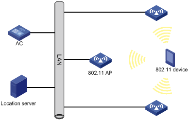
Wireless location mechanism
Wireless location operates as follows:
1. The 802.11 device sends a wireless packet.
2. Upon receiving the wireless packet, the APs encapsulate the collected location information (including RSSI and timestamp) in location packets, and then send the packets to the location server.
3. The location server calculates the location of the 802.11 device.
A location server needs location information from a minimum of three APs to locate an 802.11 device.
Configuration task list
|
Tasks at a glance |
|
(Required.) Enabling RF fingerprinting |
|
(Required.) Enabling radio-based location |
|
(Required.) Specifying an IPv4 address and a port number for the location server |
|
(Required.) Specifying a port to listen for messages from the location server |
|
(Required.) Specifying a multicast MAC address for Tags |
|
(Required.) Specifying the type of devices to locate |
|
(Optional.) Configuring raw frame reporting |
|
(Optional.) Configuring MU information reporting |
|
(Optional.) Specifying the location packet format |
|
(Optional.) Specifying the report mode for location packets |
|
(Optional.) Configuring packet dilution |
|
(Optional.) Enabling ignoring beacon frames |
|
(Optional.) Enabling ignoring AP frames |
|
(Optional.) Configuring RSSI-based packet filtering |
|
(Optional.) Configuring client packet rate limiting |
|
(Optional.) Configuring location packet rate limiting |
|
(Optional.) Configuring wireless location keepalive |
|
(Optional.) Enabling SNMP notifications for wireless location |
Configuring WLAN location
Enabling RF fingerprinting
For an AP to send location packets to the location server, you must enable both RF fingerprinting and radio-based location.
Enabling RF fingerprinting in AP view
|
Step |
Command |
Remarks |
|
1. Enter system view. |
system-view |
N/A |
|
2. Enter AP view. |
wlan ap ap-name [ model model-name ] |
N/A |
|
3. Enable RF fingerprinting. |
rfid-tracking fingerprint enable |
By default, an AP uses the configuration in AP group view. If no setting is configured in AP group view, the AP uses the configuration in global configuration view. |
Enabling RF fingerprinting in AP group view
|
Step |
Command |
Remarks |
|
1. Enter system view. |
system-view |
N/A |
|
2. Enter AP group view. |
wlan ap-group group-name |
N/A |
|
3. Enable RF fingerprinting. |
rfid-tracking fingerprint enable |
By default, an AP uses the configuration in global configuration view. |
Enabling RF fingerprinting in global configuration view
|
Step |
Command |
Remarks |
|
1. Enter system view. |
system-view |
N/A |
|
2. Enter global configuration view. |
wlan global-configuration |
N/A |
|
3. Enable RF fingerprinting. |
rfid-tracking fingerprint enable |
By default, RF fingerprinting is disabled. |
Enabling radio-based location
For an AP to send location packets to the location server, you must enable both RF fingerprinting and radio-based location.
Enabling radio-based location in radio view
|
Step |
Command |
Remarks |
|
1. Enter system view. |
system-view |
N/A |
|
2. Enter AP view. |
wlan ap ap-name [ model model-name ] |
N/A |
|
3. Enter radio view. |
radio radio-id |
N/A |
|
4. Enable radio-based location. |
rfid-tracking radio enable |
By default, an AP uses the configuration in AP group radio view. |
Enabling radio-based location in AP group radio view
|
Step |
Command |
Remarks |
|
1. Enter system view. |
system-view |
N/A |
|
2. Enter AP group view. |
wlan ap-group group-name |
N/A |
|
3. Enter AP model view. |
ap-model ap-model |
N/A |
|
4. Enter radio view. |
radio radio-id |
N/A |
|
5. Enable radio-based location. |
rfid-tracking radio enable |
By default, radio-based location is disabled. |
Specifying an IPv4 address and a port number for the location server
APs send location packets to the specified IPv4 address and port number for communicating with the location server.
Specifying an IPv4 address and a port number for the location server in AP view
|
Step |
Command |
Remarks |
|
1. Enter system view. |
system-view |
N/A |
|
2. Enter AP view. |
wlan ap ap-name [ model model-name ] |
N/A |
|
3. Specify an IPv4 address and a port number for the location server. |
rfid-tracking fingerprint engine-address engine-address engine-port engine-port |
By default, an AP uses the configuration in AP group view. If no setting is configured in AP group view, the AP uses the configuration in global configuration view. |
Specifying an IPv4 address and a port number for the location server in AP group view
|
Step |
Command |
Remarks |
|
1. Enter system view. |
system-view |
N/A |
|
2. Enter AP group view. |
wlan ap-group group-name |
N/A |
|
3. Specify an IPv4 address and a port number for the location server. |
rfid-tracking fingerprint engine-address engine-address engine-port engine-port |
By default, an AP uses the configuration in global configuration view. |
Specifying an IPv4 address and a port number for the location server in global configuration view
|
Step |
Command |
Remarks |
|
1. Enter system view. |
system-view |
N/A |
|
2. Enter global configuration view. |
wlan global-configuration |
N/A |
|
3. Specify an IPv4 address and a port number for the location server. |
rfid-tracking fingerprint engine-address engine-address engine-port engine-port |
By default, no IPv4 address and port number are specified for the location server. |
Specifying a port to listen for messages from the location server
Perform this task for an AP to communicate with the location server.
Specifying a port to listen for messages from the location server in AP view
|
Step |
Command |
Remarks |
|
1. Enter system view. |
system-view |
N/A |
|
2. Enter AP view. |
wlan ap ap-name [ model model-name ] |
N/A |
|
3. Specify a port to listen for messages from the location server. |
rfid-tracking fingerprint vendor-port vendor-port-number |
By default, an AP uses the configuration in AP group view. If no setting is configured in AP group view, the AP uses the configuration in global configuration view. |
Specifying a port to listen for messages from the location server in AP group view
|
Step |
Command |
Remarks |
|
1. Enter system view. |
system-view |
N/A |
|
2. Enter AP group view. |
wlan ap-group group-name |
N/A |
|
3. Specify a port to listen for messages from the location server. |
rfid-tracking fingerprint vendor-port vendor-port-number |
By default, an AP uses the configuration in global configuration view. |
Specifying a port to listen for messages from the location server in global configuration view
|
Step |
Command |
Remarks |
|
1. Enter system view. |
system-view |
N/A |
|
2. Enter global configuration view. |
wlan global-configuration |
N/A |
|
3. Specify a port to listen for messages from the location server. |
rfid-tracking fingerprint vendor-port vendor-port-number |
By default, the port to listen is port 1144. |
Specifying a multicast MAC address for Tags
If you do not specify a multicast MAC address for Tags, an AP determines that all received 802.11 packets are from MUs.
Specifying a multicast MAC address for Tags in AP view
|
Step |
Command |
Remarks |
|
1. Enter system view. |
system-view |
N/A |
|
2. Enter AP view. |
wlan ap ap-name [ model model-name ] |
N/A |
|
3. Specify a multicast MAC address for Tags. |
rfid-tracking fingerprint tag-multicast-address mac-address |
By default, an AP uses the configuration in AP group view. If no setting is configured in AP group view, the AP uses the configuration in global configuration view. |
Specifying a multicast MAC address for Tags in AP group view
|
Step |
Command |
Remarks |
|
1. Enter system view. |
system-view |
N/A |
|
2. Enter AP group view. |
wlan ap-group group-name |
N/A |
|
3. Specify a multicast MAC address for Tags. |
rfid-tracking fingerprint tag-multicast-address mac-address |
By default, an AP uses the configuration in global configuration view. |
Specifying a multicast MAC address for Tags in global configuration view
|
Step |
Command |
Remarks |
|
1. Enter system view. |
system-view |
N/A |
|
2. Enter global configuration view. |
wlan global-configuration |
N/A |
|
3. Specify a multicast MAC address for Tags. |
rfid-tracking fingerprint tag-multicast-address mac-address |
By default, no multicast MAC address is specified for Tags. |
Specifying the type of devices to locate
This feature enables an AP to send location information about only the specified type of devices to the location server.
Specifying the type of devices to locate in radio view
|
Step |
Command |
Remarks |
|
1. Enter system view. |
system-view |
N/A |
|
2. Enter AP view. |
wlan ap ap-name [ model model-name ] |
N/A |
|
3. Enter radio view. |
radio radio-id |
N/A |
|
4. Specify the type of devices to locate. |
rfid-tracking mode { mu | tag } * |
By default, an AP uses the configuration in AP group radio view. |
Specifying the type of devices to locate in AP group radio view
|
Step |
Command |
Remarks |
|
1. Enter system view. |
system-view |
N/A |
|
2. Enter AP group view. |
wlan ap-group group-name |
N/A |
|
3. Enter AP model view. |
ap-model ap-model |
N/A |
|
4. Enter radio view. |
radio radio-id |
N/A |
|
5. Specify the type of devices to locate. |
rfid-tracking mode { mu | tag } * |
By default, the type of devices to locate is not specified. |
Configuring raw frame reporting
This feature enables an AP to encapsulate both the raw frames and the location information obtained from the frames in location packets.
Configuring raw frame reporting in AP view
|
Step |
Command |
Remarks |
|
1. Enter system view. |
system-view |
N/A |
|
2. Enter AP view. |
wlan ap ap-name [ model model-name ] |
N/A |
|
3. Configure raw frame reporting. |
rfid-tracking fingerprint raw-frame-report { disable | enable } |
By default, an AP uses the configuration in AP group view. If no setting is configured in AP group view, the AP uses the configuration in global configuration view. |
Configuring raw frame reporting in AP group view
|
Step |
Command |
Remarks |
|
1. Enter system view. |
system-view |
N/A |
|
2. Enter AP group view. |
wlan ap-group group-name |
N/A |
|
3. Configure raw frame reporting. |
rfid-tracking fingerprint raw-frame-report { disable | enable } |
By default, an AP uses the configuration in global configuration view. |
Configuring raw frame reporting in global configuration view
|
Step |
Command |
Remarks |
|
1. Enter system view. |
system-view |
N/A |
|
2. Enter global configuration view. |
wlan global-configuration |
N/A |
|
3. Configure raw frame reporting. |
rfid-tracking fingerprint raw-frame-report { disable | enable } |
By default, raw frame reporting is disabled. |
Configuring MU information reporting
This feature enables an AP to encapsulate MU information, including the IP address and the transmit rate of an MU in location packets.
Configuring MU information reporting in AP view
|
Step |
Command |
Remarks |
|
1. Enter system view. |
system-view |
N/A |
|
2. Enter AP view. |
wlan ap ap-name [ model model-name ] |
N/A |
|
3. Configure MU information reporting. |
rfid-tracking fingerprint mu-report { disable | enable } |
By default, an AP uses the configuration in AP group view. If no setting is configured in AP group view, the AP uses the configuration in global configuration view. |
Configuring MU information reporting in AP group view
|
Step |
Command |
Remarks |
|
1. Enter system view. |
system-view |
N/A |
|
2. Enter AP group view. |
wlan ap-group group-name |
N/A |
|
3. Configure MU information reporting. |
rfid-tracking fingerprint mu-report { disable | enable } |
By default, an AP uses the configuration in global configuration view. |
Configuring MU information reporting in global configuration view
|
Step |
Command |
Remarks |
|
1. Enter system view. |
system-view |
N/A |
|
2. Enter global configuration view. |
wlan global-configuration |
N/A |
|
3. Configure MU information reporting. |
rfid-tracking fingerprint mu-report { disable | enable } |
By default, MU information reporting is disabled. |
Specifying the location packet format
RF fingerprinting supports the following location packet formats:
· CUPID-hybrid—An AP encapsulates only clients' MAC addresses and RSSIs in location packets.
· General—This format is applicable to most scenarios. Most third-party location servers support only the general format.
· Lightweight—An AP encapsulates location information for several clients in one lightweight location packet to save bandwidth. This format is applicable to traffic-sensitive scenarios.
Specifying the location packet format in AP view
|
Step |
Command |
Remarks |
|
1. Enter system view. |
system-view |
N/A |
|
2. Enter AP view. |
wlan ap ap-name [ model model-name ] |
N/A |
|
3. Specify the location packet format. |
rfid-tracking fingerprint report-format { cupid-hybrid | general | light-weight } |
By default, an AP uses the configuration in AP group view. If no setting is configured in AP group view, the AP uses the configuration in global configuration view. |
Specifying the location packet format in AP group view
|
Step |
Command |
Remarks |
|
1. Enter system view. |
system-view |
N/A |
|
2. Enter AP group view. |
wlan ap-group group-name |
N/A |
|
3. Specify the location packet format. |
rfid-tracking fingerprint report-format { cupid-hybrid | general | light-weight } |
By default, an AP uses the configuration in global configuration view. |
Specifying the location packet format in global configuration view
|
Step |
Command |
Remarks |
|
1. Enter system view. |
system-view |
N/A |
|
2. Enter global configuration view. |
wlan global-configuration |
N/A |
|
3. Specify the location packet format. |
rfid-tracking fingerprint report-format { cupid-hybrid | general | light-weight } |
By default, an AP sends location packets in general format. |
Specifying the report mode for location packets
Both the AC (centralized report) and APs (local report) can report location packets to the location server. In centralized report mode, APs need to send location packets to the AC first.
Specifying the report mode for location packets in AP view
|
Step |
Command |
Remarks |
|
1. Enter system view. |
system-view |
N/A |
|
2. Enter AP view. |
wlan ap ap-name [ model model-name ] |
N/A |
|
3. Specify the report mode for location packets. |
rfid-tracking fingerprint report-mode { central | local } |
By default, an AP uses the configuration in AP group view. If no setting is configured in AP group view, the AP uses the configuration in global configuration view. |
Specifying the report mode for location packets in AP group view
|
Step |
Command |
Remarks |
|
1. Enter system view. |
system-view |
N/A |
|
2. Enter AP group view. |
wlan ap-group group-name |
N/A |
|
3. Specify the report mode for location packets. |
rfid-tracking fingerprint report-mode { central | local } |
By default, an AP uses the configuration in global configuration view. |
Specifying the report mode for location packets in global configuration view
|
Step |
Command |
Remarks |
|
1. Enter system view. |
system-view |
N/A |
|
2. Enter AP group view. |
wlan global-configuration |
N/A |
|
3. Specify the report mode for location packets. |
rfid-tracking fingerprint report-mode { central | local } |
By default, the local report mode is used. |
Configuring packet dilution
This feature takes effect only on MU clients.
If the dilution factor is 10 and the timeout timer is 5 seconds, the AP sends a location packet every time it receives 10 wireless packets, excluding management and broadcast packets, from an MU. If the AP fails to receive 10 packets from an MU client within the timeout timer, it sends the most recent wireless packet to the location server.
Configuring packet dilution in AP view
|
Step |
Command |
Remarks |
|
1. Enter system view. |
system-view |
N/A |
|
2. Enter AP view. |
wlan ap ap-name [ model model-name ] |
N/A |
|
3. Enable packet dilution. |
rfid-tracking dilution enable |
By default, an AP uses the configuration in AP group view. If no setting is configured in AP group view, the AP uses the configuration in global configuration view. |
|
4. Set the dilution factor and dilution timeout timer. |
rfid-tracking dilution factor factor timeout timeout |
By default, an AP uses the configuration in AP group view. If no setting is configured in AP group view, the AP uses the configuration in global configuration view. |
Configuring packet dilution in AP group view
|
Step |
Command |
Remarks |
|
1. Enter system view. |
system-view |
N/A |
|
2. Enter AP group view. |
wlan ap-group group-name |
N/A |
|
3. Enable packet dilution. |
rfid-tracking dilution enable |
By default, an AP uses the configuration in global configuration view. |
|
4. Set the dilution factor and dilution timeout timer. |
rfid-tracking dilution factor factor timeout timeout |
By default, an AP uses the configuration in global configuration view. |
Configuring packet dilution in global configuration view
|
Step |
Command |
Remarks |
|
1. Enter system view. |
system-view |
N/A |
|
2. Enter global configuration view. |
wlan global-configuration |
N/A |
|
3. Enable packet dilution. |
rfid-tracking dilution enable |
By default, packet dilution is disabled. |
|
4. Set the dilution factor and dilution timeout timer. |
rfid-tracking dilution factor factor timeout timeout |
By default, the dilution factor and dilution timeout timer are not configured. |
Enabling ignoring beacon frames
This feature disables an AP from reporting the location information in beacon frames to the location server to prevent traffic flood caused by location packets.
Enabling ignoring beacon frames in AP view
|
Step |
Command |
Remarks |
|
1. Enter system view. |
system-view |
N/A |
|
2. Enter AP view. |
wlan ap ap-name [ model model-name ] |
N/A |
|
3. Enable the AP to ignore beacon frames. |
rfid-tracking ignore beacon enable |
By default, an AP uses the configuration in AP group view. If no setting is configured in AP group view, the AP uses the configuration in global configuration view. |
Enabling ignoring beacon frames in AP group view
|
Step |
Command |
Remarks |
|
1. Enter system view. |
system-view |
N/A |
|
2. Enter AP group view. |
wlan ap-group group-name |
N/A |
|
3. Enable APs in the AP group to ignore beacon frames. |
rfid-tracking ignore beacon enable |
By default, an AP uses the configuration in global configuration view. |
Enabling ignoring beacon frames in global configuration view
|
Step |
Command |
Remarks |
|
1. Enter system view. |
system-view |
N/A |
|
2. Enter global configuration view. |
wlan global-configuration |
N/A |
|
3. Enable APs to ignore beacon frames. |
rfid-tracking ignore beacon enable |
By default, beacon frames are not ignored. |
Enabling ignoring AP frames
AP frames are frames that an AP received from other APs. Configure this feature if you do not need to locate or monitor APs.
Enabling ignoring AP frames in AP view
|
Step |
Command |
Remarks |
|
1. Enter system view. |
system-view |
N/A |
|
2. Enter AP view. |
wlan ap ap-name [ model model-name ] |
N/A |
|
3. Enable the AP to ignore AP frames. |
rfid-tracking ignore ap-frame enable |
By default, an AP uses the configuration in AP group view. If no setting is configured in AP group view, the AP uses the configuration in global configuration view. |
Enabling ignoring AP frames in AP group view
|
Step |
Command |
Remarks |
|
1. Enter system view. |
system-view |
N/A |
|
2. Enter AP group view. |
wlan ap-group group-name |
N/A |
|
3. Enable APs in the AP group to ignore AP frames. |
rfid-tracking ignore ap-frame enable |
By default, an AP uses the configuration in global configuration view. |
Enabling ignoring AP frames in global configuration view
|
Step |
Command |
Remarks |
|
1. Enter system view. |
system-view |
N/A |
|
2. Enter global configuration view. |
wlan global-configuration |
N/A |
|
3. Enable APs to ignore AP frames. |
rfid-tracking ignore ap-frame enable |
By default, AP frames are not ignored. |
Configuring RSSI-based packet filtering
When RSSI-based packet filtering is enabled, an AP does not report location information in packets with an RSSI lower than the RSSI threshold. This feature enables an AP to not locate clients far away from the AP.
Configuring RSSI-based packet filtering in AP view
|
Step |
Command |
Remarks |
|
1. Enter system view. |
system-view |
N/A |
|
2. Enter AP view. |
wlan ap ap-name [ model model-name ] |
N/A |
|
3. Enable RSSI-based packet filtering. |
rfid-tracking rssi enable |
By default, an AP uses the configuration in AP group view. If no setting is configured in AP group view, the AP uses the configuration in global configuration view. |
|
4. Set the RSSI threshold. |
rfid-tracking rssi threshold rssi-threshold |
By default, an AP uses the configuration in AP group view. If no setting is configured in AP group view, the AP uses the configuration in global configuration view. |
Configuring RSSI-based packet filtering in AP group view
|
Step |
Command |
Remarks |
|
1. Enter system view. |
system-view |
N/A |
|
2. Enter AP group view. |
wlan ap-group group-name |
N/A |
|
3. Enable RSSI-based packet filtering. |
rfid-tracking rssi enable |
By default, an AP uses the configuration in global configuration view. |
|
4. Set the RSSI threshold. |
rfid-tracking rssi threshold rssi-threshold |
By default, an AP uses the configuration in global configuration view. |
Configuring RSSI-based packet filtering in global configuration view
|
Step |
Command |
Remarks |
|
1. Enter system view. |
system-view |
N/A |
|
2. Enter global configuration view. |
wlan global-configuration |
N/A |
|
3. Enable RSSI-based packet filtering. |
rfid-tracking rssi enable |
By default, RSSI-based packet filtering is disabled. |
|
4. Set the RSSI threshold. |
rfid-tracking rssi threshold rssi-threshold |
By default, the RSSI threshold is 5 (–123 dBm). |
Configuring client packet rate limiting
If packet dilution is enabled, this feature limits the rate for diluted packets.
This feature enables an AP to not report location information from excessive client packets when both the CIR and CBS are exceeded. This practice ensures that the location information for each client can be sent to the location server and prevents client packets from flooding the AP.
Configuring client packet rate limiting in AP view
|
Step |
Command |
Remarks |
|
1. Enter system view. |
system-view |
N/A |
|
2. Enter AP view. |
wlan ap ap-name [ model model-name ] |
N/A |
|
3. Enable client packet rate limiting. |
rfid-tracking client rate-limit enable |
By default, an AP uses the configuration in AP group view. If no setting is configured in AP group view, the AP uses the configuration in global configuration view. |
|
4. Set the CIR and CBS for client packets. |
rfid-tracking client rate-limit cir cir [ cbs cbs ] |
By default, an AP uses the configuration in AP group view. If no setting is configured in AP group view, the AP uses the configuration in global configuration view. |
Configuring client packet rate limiting in AP group view
|
Step |
Command |
Remarks |
|
1. Enter system view. |
system-view |
N/A |
|
2. Enter AP group view. |
wlan ap-group group-name |
N/A |
|
3. Enable client packet rate limiting. |
rfid-tracking client rate-limit enable |
By default, an AP uses the configuration in global configuration view. |
|
4. Set the CIR and CBS for client packets. |
rfid-tracking client rate-limit cir cir [ cbs cbs ] |
By default, an AP uses the configuration in global configuration view. |
Configuring client packet rate limiting in global configuration view
|
Step |
Command |
Remarks |
|
1. Enter system view. |
system-view |
N/A |
|
2. Enter global configuration view. |
wlan global-configuration |
N/A |
|
3. Enable client packet rate limiting. |
rfid-tracking client rate-limit enable |
By default, client packet rate limiting is disabled. |
|
4. Set the CIR and CBS for client packets. |
rfid-tracking client rate-limit cir cir [ cbs cbs ] |
By default, the CIR and CBS for client packets are 0. |
Configuring location packet rate limiting
This feature enables an AP to discard excessive location packets when both the CIR and CBS are exceeded. This practice prevents location packets from flooding the location server.
Configuring location packet rate limiting in AP view
|
Step |
Command |
Remarks |
|
1. Enter system view. |
system-view |
N/A |
|
2. Enter AP view. |
wlan ap ap-name [ model model-name ] |
N/A |
|
3. Enable location packet rate limiting. |
rfid-tracking rate-limit enable |
By default, an AP uses the configuration in AP group view. If no setting is configured in AP group view, the AP uses the configuration in global configuration view. |
|
4. Set the CIR and CBS for location packets. |
rfid-tracking rate-limit cir cir [ cbs cbs ] |
By default, an AP uses the configuration in AP group view. If no setting is configured in AP group view, the AP uses the configuration in global configuration view. |
Configuring location packet rate limiting in AP group view
|
Step |
Command |
Remarks |
|
1. Enter system view. |
system-view |
N/A |
|
2. Enter AP group view. |
wlan ap-group group-name |
N/A |
|
3. Enable location packet rate limiting. |
rfid-tracking rate-limit enable |
By default, an AP uses the configuration in global configuration view. |
|
4. Set the CIR and CBS for location packets. |
rfid-tracking rate-limit cir cir [ cbs cbs ] |
By default, an AP uses the configuration in global configuration view. |
Configuring location packet rate limiting in global configuration view
|
Step |
Command |
Remarks |
|
1. Enter system view. |
system-view |
N/A |
|
2. Enter global configuration view. |
wlan global-configuration |
N/A |
|
3. Enable location packet rate limiting. |
rfid-tracking rate-limit enable |
By default, location packet rate limiting is disabled. |
|
4. Set the CIR and CBS for location packets. |
rfid-tracking rate-limit cir cir [ cbs cbs ] |
By default, the CIR and CBS for location packets are 0. |
Configuring wireless location keepalive
This feature enables an AP to send Hello packets to the location server at an interval of 15 seconds. If the location server does not receive any packets from an AP within 30 seconds, the location server determines that the AP is offline.
Disable this feature to avoid bandwidth waste if the location server cannot process Hello packets.
Configuring wireless location keepalive in AP view
|
Step |
Command |
Remarks |
|
1. Enter system view. |
system-view |
N/A |
|
2. Enter AP view. |
wlan ap ap-name [ model model-name ] |
N/A |
|
3. Configure wireless location keepalive. |
rfid-tracking keepalive { disable | enable } |
By default, an AP uses the configuration in AP group view. If no setting is configured in AP group view, the AP uses the configuration in global configuration view. |
Configuring wireless location keepalive in AP group view
|
Step |
Command |
Remarks |
|
1. Enter system view. |
system-view |
N/A |
|
2. Enter AP group view. |
wlan ap-group group-name |
N/A |
|
3. Configure wireless location keepalive. |
rfid-tracking keepalive { disable | enable } |
By default, an AP uses the configuration in global configuration view. |
Configuring wireless location keepalive in global configuration view
|
Step |
Command |
Remarks |
|
1. Enter system view. |
system-view |
N/A |
|
2. Enter global configuration view. |
wlan global-configuration |
N/A |
|
3. Configure wireless location keepalive. |
rfid-tracking keepalive { disable | enable } |
By default, wireless location keepalive is disabled. |
Enabling SNMP notifications for wireless location
Perform this task for the device to report critical wireless location events to an NMS. For wireless location notifications to be sent correctly, you must also configure SNMP on the device. For more information about SNMP configuration, see Network Management and Monitoring Configuration Guide.
To enable SNMP notifications for wireless location:
|
Step |
Command |
Remarks |
|
1. Enter system view. |
system-view |
N/A |
|
2. Enable SNMP notifications for wireless location. |
snmp-agent trap enable wlan location-aware |
By default, SNMP notifications for wireless location is disabled. |
Displaying and maintaining wireless location
Execute display commands in any view.
|
Task |
Command |
|
Display radio information for WLAN location. |
display wlan rfid-tracking radio [ ap apname ] |
Wireless location configuration example
Network requirements
As shown in Figure 93, configure RF fingerprinting for AP 1, AP 2, and AP 3 to locate the MUs.
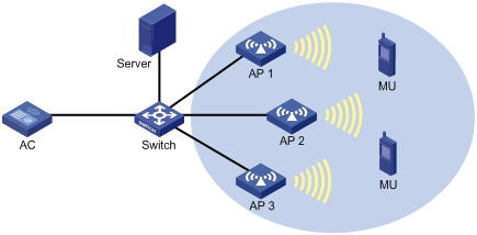
Configuration procedure
1. Configure AP 1:
# Create manual AP ap1, and specify the AP model and serial ID.
<AC> system-view
[AC] wlan ap ap1 model WA536-WW
[AC-wlan-ap-ap1] serial-id 219801A1NQB117012935
[AC-wlan-ap-ap1] quit
# Enable RF fingerprinting.
[AC-wlan-ap-ap1] rfid-tracking fingerprint enable
# Specify an IPv4 address and a port number for the location server.
[AC-wlan-ap-ap1] rfid-tracking fingerprint engine-address 192.168.10.10 engine-port 1145
# Specify a port to listen for messages from the location server.
[AC-wlan-ap-ap1] rfid-tracking fingerprint vendor-port 3000
# Enable radio-based location.
[AC-wlan-ap-ap1] radio 1
[AC-wlan-ap-ap1-radio-1] rfid-tracking radio enable
# Specify the type of devices to locate as MU.
[AC-wlan-ap-ap1-radio-1] rfid-tracking mode mu
# Enable radio 1 of AP 1.
[AC-wlan-ap-ap1-radio-1] radio enable
[AC-wlan-ap-ap1-radio-1] quit
[AC-wlan-ap-ap1] quit
[AC] quit
2. Configure AP 2 and AP 3 in the same way AP 1 is configured.
Verifying the configuration
# Verify that RF fingerprinting is enabled and the type of devices to locate is MU for each AP.
<AC> display wlan rfid-tracking radio
Wireless Locating
--------------------------------------------------------------------------------
AP Radio Type
--------------------------------------------------------------------------------
ap1 1 MU
ap2 1 MU
ap3 1 MU
--------------------------------------------------------------------------------
# Verify that you can view location information for the MUs by maps, forms, or reports provided by the graphics software. (Details not shown.)
Configuring Hotspot 2.0
Overview
Hotspot 2.0, developed by Wi-Fi Alliance, provides automatic network discovery, automated authentication, and seamless roaming for wireless clients.
Hotspot 2.0 contains two versions. Version 2 is fully compatible with version 1.
Hotspot 2.0 operating mechanism
Hotspot 2.0 operates as follows:
1. A client performs wireless scanning to discover Hotspot 2.0 networks.
2. The client exchanges Generic Advertisement Service (GAS) frames with APs to get Hotspot 2.0 information and select an optimal BSS.
3. The client performs online signup. This step is required only for version 2 of Hotspot 2.0.
Scanning
Active scanning
A wireless client periodically scans surrounding wireless networks by sending probe requests. It obtains network information from probe responses.
As shown in Figure 94, the client periodically sends a probe request on each of its supported channels to scan wireless networks. APs that receive the probe request send a probe response that carries the available wireless network information.
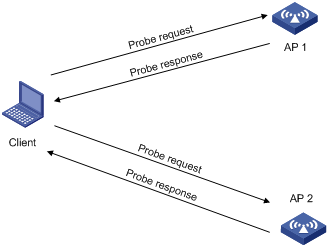
Passive scanning
As shown in Figure 95, the clients periodically listen for beacon frames sent by APs on their supported channels to get information about surrounding wireless networks. Passive scanning is used when clients want to save power.
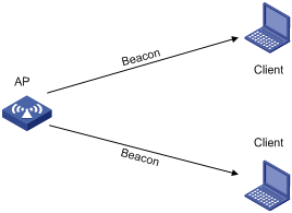
GAS frame exchange
After discovering Hotspot 2.0 networks by active or passive scanning, a client exchanges GAS frames with APs to get APs' Hotspot 2.0 information. Based on the obtained Hotspot 2.0 information and local configuration, the client selects an optimal BSS.
As shown in Figure 96, a client exchanges GAS frames with an AP by using the following process:
1. The client sends a GAS initial request.
2. Upon receiving the request, the AP encapsulates Hotspot 2.0 information in a GAS initial response and examines the length of the response.
? If the length does not exceed the limit, the AP sends the GAS initial response to the client. The GAS frame exchange is complete and the client can send an authentication request.
? If the length exceeds the limit, the AP fragments the response and sends the first fragment in a GAS initial response to the client. The response notifies the client to request Hotspot 2.0 information after a comeback delay.
3. The client sends a GAS comeback request to the AP after a comeback delay.
4. The AP sends a GAS comeback response that carries the second fragment to the client.
5. If the length of the response exceeds the limit, the client and the AP repeat steps 3 and 4 until all fragments are sent to the client.
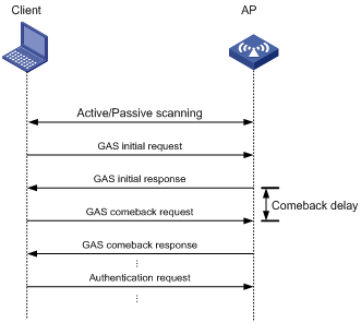
Online signup
After GAS frame exchange, a client connects to the Online Sign Up (OSU) server through the OSU AP to sign up online. A signed-up client gets a credential and can automatically access a Hotspot 2.0 network without being re-authenticated. A client can associate with an OSU AP by using the following methods:
· Open OSU—No authentication.
· OSEN OSU—Layer 2 authentication.
As shown in Figure 97, online signup operates as follows:
1. The client obtains the OSU server list from the AP by exchanging GAS frames with the AP and selects an OSU server.
2. The client associates with the OSU AP through open OSU or OSEN OSU.
3. The OSU server sends a credential and authentication information to the client or updates the expired credential for the client.
4. Using the newly provisioned credential, the client disassociates from the OSU AP and associates with the AP that provides Hotspot 2.0 services.
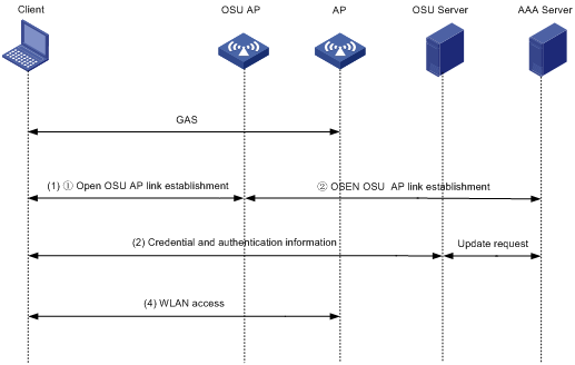
Protocols and standards
· Wi-Fi Alliance Technical Committee Hotspot 2.0 Technical Task Group Hotspot 2.0 (Release 2)Technical Specification Version 3.04
Configuration task list
|
Tasks at a glance |
Remarks |
|
(Required.) Configuring a Hotspot 2.0 policy |
N/A |
|
(Optional.) Configuring 3GPP information |
N/A |
|
(Optional.) Setting an HESSID |
Required for version 2 of Hotspot 2.0. |
|
(Optional.) Setting the access network type |
N/A |
|
(Optional.) Specifying a network authentication type |
N/A |
|
(Optional.) Setting the domain name |
Required for version 2 of Hotspot 2.0. |
|
(Optional.) Specifying an OI |
Required for version 2 of Hotspot 2.0. |
|
(Optional.) Configuring IP address availability |
N/A |
|
(Optional.) Specifying an authentication type for an NAI realm |
N/A |
|
(Optional.) Setting service provider information |
N/A |
|
(Optional.) Setting the port status for an IP protocol |
N/A |
|
(Optional.) Setting WAN link status parameters |
N/A |
|
(Optional.) Disabling the DGAF feature |
N/A |
|
(Optional.) Managing GAS frames |
N/A |
|
(Optional.) Configuring AP venue information |
N/A |
|
(Required.) Configuring a OSU server |
Required only for version 2 of Hotspot 2.0. |
|
(Required.) Setting an SSID for online signup services |
Required only for version 2 of Hotspot 2.0. |
|
(Required.) Managing OSU server icons |
Required only for version 2 of Hotspot 2.0. |
|
(Required.) Binding an OSU server to a Hotspot 2.0 policy |
Required only for version 2 of Hotspot 2.0. |
Configuring a Hotspot 2.0 policy
A Hotspot 2.0 policy defines a set of Hotspot 2.0 parameters.
To configure a Hotspot 2.0 policy:
|
Step |
Command |
Remarks |
|
1. Enter system view. |
system-view |
N/A |
|
2. Create a Hotspot 2.0 policy and enter its view. |
By default, no Hotspot 2.0 policy exists. |
|
|
3. Specify a name for the Hotspot 2.0 policy. |
policy-name name |
By default, no name is specified for a Hotspot 2.0 policy. |
Configuring 3GPP information
The 3rd Generation Partnership Project (3GPP) information contains a country code and a network code. The country code identifies a country, and the network code identifies a service provider in the country.
To configure 3GPP information:
|
Step |
Command |
Remarks |
|
1. Enter system view. |
system-view |
N/A |
|
2. Enter service template view. |
wlan service-template service-template-name |
N/A |
|
3. Configure 3GPP information. |
3gpp-info country-code mobile-country-code network-code mobile-network-code |
By default, no country code and network code are configured. |
Setting an HESSID
A homogenous ESS identifier (HESSID) and the SSID for the extended service set (ESS) together uniquely identify a WLAN. Set the HESSID to the same value as a BSSID in the ESS.
To set an HESSID:
|
Step |
Command |
Remarks |
|
1. Enter system view. |
system-view |
N/A |
|
2. Enter Hotspot 2.0 policy view. |
N/A |
|
|
3. Set an HESSID. |
By default, no HESSID is set. |
Setting the access network type
You can set the following access network types:
· 0—Private network.
· 1—Private network with guest access.
· 2—Chargeable public network.
· 3—Free public network.
· 4—Personal device network.
· 5—Emergency services only network.
· 14—Test or experimental.
· 15—Wildcard.
To set the access network type:
|
Step |
Command |
Remarks |
|
1. Enter system view. |
system-view |
N/A |
|
2. Enter Hotspot 2.0 policy view. |
wlan hotspot-policy policy-number |
N/A |
|
3. Set the access network type. |
By default, no access network type is set. |
Specifying a network authentication type
You can specify the following network authentication types:
· 0—Acceptance of terms and conditions.
· 1—On-line enrollment.
· 2—HTTP/HTTPS redirection.
· 3—DNS redirection.
To specify a network authentication type:
|
Step |
Command |
Remarks |
|
1. Enter system view. |
system-view |
N/A |
|
2. Enter Hotspot 2.0 policy view. |
wlan hotspot-policy policy-number |
N/A |
|
3. Specify a network authentication type. |
authentication-type { 0 [ redirect-url redirect-url ] | 1 | 2 redirect-url redirect -url | 3 } |
By default, no network authentication type is specified. |
Setting the domain name
|
Step |
Command |
Remarks |
|
1. Enter system view. |
system-view |
N/A |
|
2. Enter Hotspot 2.0 policy view. |
wlan hotspot-policy policy-number |
N/A |
|
3. Set the domain name. |
domain-name domain-name |
By default, the domain name is not set. |
Specifying an OI
An organization identifier (OI) identifies a roaming consortium. If a client has the certificate to a roaming consortium, the client can roam to all wireless services provided by the roaming consortium.
To specify an OI:
|
Step |
Command |
Remarks |
|
1. Enter system view. |
system-view |
N/A |
|
2. Enter Hotspot 2.0 policy view. |
wlan hotspot-policy policy-number |
N/A |
|
3. Specify an OI. |
roam-oi oi [ in-beacon ] |
By default, no OI is specified. |
Configuring IP address availability
Perform this task to configure IP address availability. IP address availability specifies the version and type of IP addresses that an AP assigns to associated clients.
· IPv4 address availability.
? 0—Address type not available.
? 1—Public IPv4 address available.
? 2—Port-restricted IPv4 address available.
? 3—Single NATed private IPv4 address available.
? 4—Double NATed private IPv4 address available.
? 5—Port-restricted IPv4 address and single NATed IPv4 address available.
? 6—Port-restricted IPv4 address and double NATed IPv4 address available.
? 7—Availability of the address type is not known.
· IPv6 address availability.
? 0—Address type not available.
? 1—Address type available.
? 2—Availability of the address type not known.
To configure IP address availability:
|
Step |
Command |
Remarks |
|
1. Enter system view. |
system-view |
N/A |
|
2. Enter Hotspot 2.0 policy view. |
wlan hotspot-policy policy-number |
N/A |
|
3. Configure IP address availability. |
ip-type ipv4 ipv4-type ipv6 ipv6-type |
By default, the availability is 1 for an IPv4 address and 2 for an IPv6 address. |
Specifying an authentication type for an NAI realm
|
Step |
Command |
Remarks |
|
1. Enter system view. |
system-view |
N/A |
|
2. Enter Hotspot 2.0 policy view. |
wlan hotspot-policy policy-number |
N/A |
|
3. Create an NAI realm and specify an authentication type for the NAI realm. |
nai-realm realm-name eap-method eap-method-id auth-method auth-method-id authentication authentication |
By default, no NAI realm is created. |
Setting service provider information
|
Step |
Command |
Remarks |
|
1. Enter system view. |
system-view |
N/A |
|
2. Enter Hotspot 2.0 policy view. |
wlan hotspot-policy policy-number |
N/A |
|
3. Set service provider information. |
operator-name operator-name lang-code lang-code |
By default, no service provider information is set. |
Setting the port status for an IP protocol
|
Step |
Command |
Remarks |
|
1. Enter system view. |
system-view |
N/A |
|
2. Enter Hotspot 2.0 policy view. |
wlan hotspot-policy policy-number |
N/A |
|
3. Set the port status for an IP protocol. |
ip-protocol { esp | icmp | tcp | udp } port-number port-number { closed | open | unknown } |
By default, no port status is set for an IP protocol. |
Setting WAN link status parameters
This feature enables Hotspot 2.0 to advertise uplink and downlink speeds and link status such as closed, testing, and enabled of the WAN.
To set WAN link status parameters:
|
Step |
Command |
Remarks |
|
1. Enter system view. |
system-view |
N/A |
|
2. Enter Hotspot 2.0 policy view. |
wlan hotspot-policy policy-number |
N/A |
|
3. Set WAN link status parameters. |
wan-metrics { link-down | link-test | link-up } [ asymmetric downlink-speed downlink-speed uplink-speed uplink-speed | symmetric link-speed link-speed ] |
By default, no WAN link status parameters are set. |
Disabling the DGAF feature
The Downstream Group-Addressed Forwarding (DGAF) feature enables an AP to forward all downstream wireless broadcast ARP packets and wireless multicast packets. To prevent spoofing attacks by using downstream multicasts, you can disable the DGAF feature for the AP.
To avoid packet loss, enable proxy ARP and multicast optimization before disabling DGAF. For more information about proxy ARP, see Layer 3—IP Services Configuration Guide.
To disable the DGAF feature:
|
Step |
Command |
Remarks |
|
1. Enter system view. |
system-view |
N/A |
|
2. Enter Hotspot 2.0 policy view. |
wlan hotspot-policy policy-number |
N/A |
|
3. Disable the DGAF feature. |
undo dgaf enable |
By default, the DGAF feature is enabled. Before disabling DGAF, make sure all service templates bound to the Hotspot 2.0 policy are disabled. |
Managing GAS frames
|
Step |
Command |
Remarks |
|
1. Enter system view. |
system-view |
N/A |
|
2. Enter Hotspot 2.0 policy view. |
wlan hotspot-policy policy-number |
N/A |
|
3. Set the comeback delay. |
comeback-delay value |
By default, the comeback delay is 1 TU (1024 milliseconds). The comeback delay prevents clients from frequently sending GAS comeback requests. |
|
4. Set the maximum number of GAS initial requests that clients can send within the specified interval. |
gas-limit number number interval interval |
By default, the number of GAS initial requests that clients can send is not limited. This command can ease the AC's burden. |
Binding a Hotspot 2.0 policy to a service template
Before you bind a Hotspot 2.0 policy to a service template, make sure the following settings are configured for the service template:
· 802.1X authentication and key management mode.
· RSN IE.
· AES-CCMP cipher suite.
To bind a Hotspot 2.0 policy to a service template:
|
Step |
Command |
Remarks |
|
1. Enter system view. |
system-view |
N/A |
|
2. Enter service template view. |
wlan service-template service-template-name |
N/A |
|
3. Bind a Hotspot 2.0 policy to the service template. |
hotspot-policy policy-number |
By default, no Hotspot 2.0 policy is bound to a service template. |
Configuring AP venue information
AP venue information indicates the location of APs and helps clients connect to an optimal AP.
To configure AP venue information:
|
Step |
Command |
Remarks |
|
1. Enter system view. |
system-view |
N/A |
|
2. Enter AP view. |
N/A |
|
|
3. Specify the venue group and venue type for the AP. |
venue group venue-group-number type venue-type-number |
By default, no venue group and venue type are specified for an AP. |
|
4. Set a venue name for the AP. |
By default, no venue name is set for an AP. |
Configuring a OSU server
This task is required only for version 2 of Hotspot 2.0.
To configure an OSU server:
|
Step |
Command |
Remarks |
|
5. Enter system view. |
system-view |
N/A |
|
6. Create an OSU server and enter its view, or enter the view of an existing OSU server. |
wlan osu-provider osu-provider-number |
By default, no OSU server exists. |
|
7. Set a name for the OSU server. |
friendly-name friendly-name lang-code lang-code |
By default, no name is set for an OSU server. |
|
8. Specify the URI of the OSU server. |
uri uri |
By default, no URI is specified for an OSU server. |
|
9. Specify a protocol for clients to communicate with the OSU server. |
method method-id |
By default, no method is specified for clients to communicate with an OSU server. |
|
10. Specify an icon for the OSU server. |
icon-file filename lang-code lang-code icon-type icon-type |
By default, no icon is specified for an OSU server. Before specifying an icon for an OSU server, make sure directory icon has been created by using the mkdir command in the root directory where the version files are saved. Then use FTP or TFTP to download icon files to the directory. |
|
11. (Optional.) Configure a description for the OSU server. |
description description lang-code lang-code |
By default, no description is configured for an OSU server. |
|
12. (Optional.) Configure a Network Access Identifier (NAI) for the OSU server. |
nai nai |
By default, no NAI is configured for an OSU server. |
Setting an SSID for online signup services
This task is required only for version 2 of Hotspot 2.0.
Hotspot 2.0 provides different SSIDs for online signup services and wireless services.
Make sure the configured SSID for online signup services is the same as the SSID for the online signup service template.
To set an SSID for online signup services:
|
Step |
Command |
Remarks |
|
13. Enter system view. |
system-view |
N/A |
|
14. Enter Hotspot 2.0 policy view. |
wlan hotspot-policy policy-number |
N/A |
|
15. Set an SSID for online signup services. |
osu-ssid ssid-name |
By default, no SSID is set for online signup services. |
Managing OSU server icons
This task is required only for version 2 of Hotspot 2.0.
Perform this task to load all icon files specified for an OSU server to validate the changes when icon file changes occur or to invalidate icon files.
To manage an OSU server icon:
|
Step |
Command |
|
|
16. Enter system view. |
system-view |
|
|
17. Manage OSU server icon files. |
· Load OSU server icon files: · Unload OSU server icon files: |
|
Binding an OSU server to a Hotspot 2.0 policy
This task is required only for version 2 of Hotspot 2.0.
A Hotspot 2.0 policy can be bound to a maximum of 32 OSU servers.
Make sure all configuration required for an OSU server has been completed before binding the OSU server to a Hotspot 2.0 policy.
To bind an OSU server to a Hotspot 2.0 policy:
|
Step |
Command |
Remarks |
|
1. Enter system view. |
system-view |
N/A |
|
2. Enter Hotspot 2.0 policy view. |
wlan hotspot-policy policy-number |
N/A |
|
3. Bind an OSU server to the Hotspot 2.0 policy. |
osu-provider osu-provider-number |
By default, no OSU server is bound to a Hotspot 2.0 policy. |
Displaying and maintaining Hotspot 2.0
Execute display commands in any view.
|
Task |
Command |
|
Display service template information. |
display wlan service-template [ service-template-name ] [ verbose ] |
|
Display all the loaded OSU server icon files. |
display wlan hotspot uploaded-osu-icon |
Hotspot 2.0 configuration examples
iPhone application
Network requirements
As shown in Figure 98, configure Hotspot 2.0 to enable the phone to switch from the cellular network to the wireless network.

Configuration restrictions and guidelines
Make sure you have installed certificates and created a user account on the RADIUS server, so that client authentication, authorization, and accounting can operate correctly.
For more information about AAA, see Security Configuration Guide.
Configuration procedures
Configuring the AC
1. Configure a Hotspot 2.0 policy:
# Create the Hotspot 2.0 policy 1.
<AC> system-view
[AC] wlan hotspot-policy 1
# Configure EAP-TLS authentication.
[AC-wlan-hs-1] nai-realm h3c.com eap-method 6 auth-method 2 authentication 4
# Set the domain name to h3c.com.
[AC-wlan-hs-1] domain-name h3c.com
# Set the HESSID to 1232-ff23-0123.
[AC-wlan-hs-1] hessid 1232-ff23-0123
[AC-wlan-hs-1] quit
2. Configure 802.1X authentication and the RADIUS scheme:
# Configure the 802.1X authentication method as EAP.
[AC] dot1x authentication-method eap
# Create RADIUS scheme imcc.
[AC] radius scheme imcc
# Set the IP address and the port number of the primary authentication server to 10.18.1.88 and 1812, respectively.
[AC-radius-imcc] primary authentication 10.18.1.88 1812
# Set the IP address and the port number of the primary accounting server to 10.18.1.88 and 1813, respectively.
[AC-radius-imcc] primary accounting 10.18.1.88 1813
# Set the shared key for the AC to exchange packets with the authentication and accounting servers to 12345678.
[AC-radius-imcc] key authentication simple 12345678
[AC-radius-imcc] key accounting simple 12345678
# Configure the AC to remove the domain name in the username sent to the RADIUS servers.
[AC-radius-imcc] user-name-format without-domain
[AC-radius-imcc] quit
3. Create the domain imc and configure the domain to use the RADIUS scheme imcc for authentication, authorization, and accounting.
[AC] domain imc
[AC-isp-imc] authentication lan-access radius-scheme imcc
[AC-isp-imc] authorization lan-access radius-scheme imcc
[AC-isp-imc] accounting lan-access radius-scheme imcc
[AC-isp-imc] quit
Configuring the AP
# Create the service template service1.
<AC> system-view
[AC] wlan service-template service1
# Set the SSID to service.
[AC-wlan-st-service1] ssid service
# Bind the Hotspot 2.0 policy 1 to the service template.
[AC-wlan-st-service1] hotspot-policy 1
# Enable the RSN IE in beacons and probe responses.
[AC-wlan-st-service1] security-ie rsn
# Enable the AES-CCMP cipher suite.
[AC-wlan-st-service1] cipher-suite ccmp
# Set the authentication and key management mode to 802.1X.
[AC-wlan-st-service1] akm mode dot1x
# Set the authentication mode for WLAN clients to 802.1X.
[AC-wlan-st-service1] client-security authentication-mode dot1x
# Specify the domain imc as the authentication domain.
[AC-wlan-st-service1] dot1x domain imc
# Enable the service template.
[AC-wlan-st-service1] service-template enable
[AC-wlan-st-service1] quit
# Create the AP ap1, and specify the AP model and serial ID.
[AC] wlan ap ap1 model WA536-WW
[AC-wlan-ap-ap1] serial-id 219801A0CNC138011454
# Bind the service template service1 to radio 2 of the AP.
[AC-wlan-ap-ap1] radio 2
[AC-wlan-ap-ap1-radio-2] radio enable
[AC-wlan-ap-ap1-radio-2] service-template service1
[AC-wlan-ap-ap1-radio-2] quit
[AC-wlan-ap-ap1] quit
Configuring the RADIUS server (IMCv7)
This example was created on IMC PLAT 7.1 and IMC UAM 7.1.
To configure the IMC server:
1. Log in to the IMC platform.
2. Click the User tab.
3. Add an access device:
a. From the navigation tree, select User Access Policy > Access Device Management > Access Device.
b. On the access device configuration page, click Add.
c. On the Add Access Device page, configure the following parameters:
- Set the shared key to 12345678.
- Select or manually add the device with the IP address 10.18.1.1 (IP address of the AC).
- Use the default settings for other parameters.
d. Click OK.
Figure 99 Adding an access device
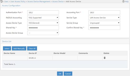
4. Add an access policy:
a. From the navigation tree, select User Access Policy > Access Policy.
b. On the access policy configuration page, click Add.
c. On the Add Access Policy page, configure the following parameters:
- Set the access policy name to 802.1X_policy.
- Select EAP-PEAP Authentication from the Certificate Type list, and from the Certificate Sub-Type list, select the certificate sub-type, which must be the same as the authentication method for the client.
- Use the default settings for other parameters.
Figure 100 Adding an access policy

5. Add an access service:
a. From the navigation tree, select User Access Policy > Access Service.
b. On the access service configuration page, click Add.
c. On the Add Access Service page, configure the service name as 802.1X_ser, and use the 802.1X policy you have created as the default access policy.
d. Use the default settings for other parameters.
Figure 101 Adding an access service
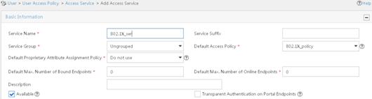
6. Add an access user:
a. From the navigation tree, select Access User > All Access Users.
b. On the access user configuration page, click Add.
c. On the Add Access User page, click Add User.
d. On the Add User window, configure the following parameters:
- Set the username to admin.
- Set the account name to admin.
- Select the 802.1X user 802.1X_ser you have configured in the Access Service area..
Figure 102 Adding an access user
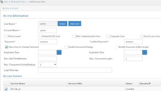
Configuring the phone
This example was created using an iPhone 5S.
To configure the phone:
1. Install the Apple Configurator App on the MacBook Air and connect iPhone 5S to the laptop.
Figure 103 Apply Configurator App

2. Open the Apple Configurator App and select Supervise from the top menu. Then click + under the Profiles list and select Create New Profile.
Figure 104 Creating a new profile
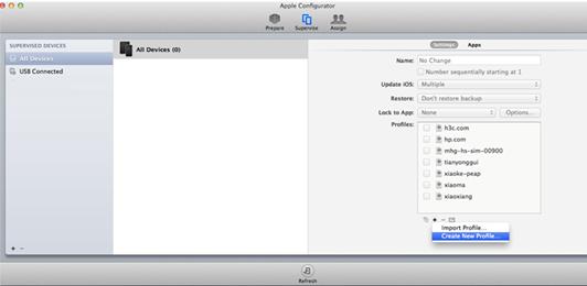
3. Click General on the left navigation tree, and enter h3c.com in the Name field. Other parameters are optional.
Figure 105 General settings
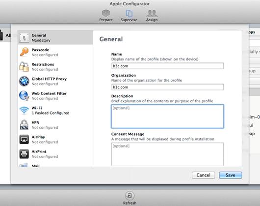
4. Click Wi-Fi on the left navigation tree and click Configure from the menu. Then select Passpoint from the Network Type list.
Figure 106 Enabling passpoint
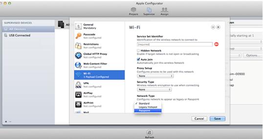
5. On the page that appears, perform the following tasks:
? In the Accepted EAP Types area, select PEAP.
? Enter admin and 12345678 in the Username area and Password area, respectively.
? Select None from the Identity Certificate list.
? Enter admin in the Outer Identity area.
Figure 107 Configuring EAP-PEAP authentication
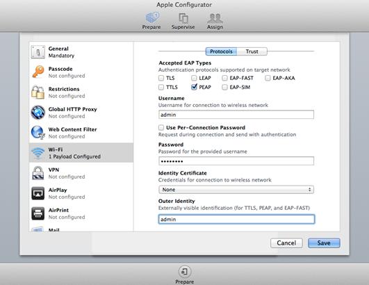
? Enter h3c.com in the Provider Display Name field and enter the domain name that you have configured in the hotspot policy on the AC.
Figure 108 Configuring the domain name
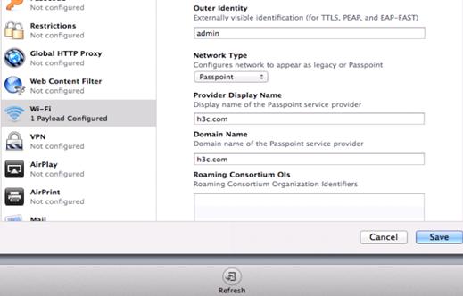
? Leave Roaming Consortium Ols, NAI Real Names, and MCC/MNC blank, or enter the values you have configured in the hotspot policy on the AC. Then click Save.
Figure 109 Configuring other options
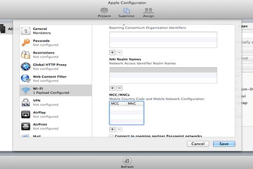
6. Click Prepare and then click Install Profiles on the Settings tab.
Figure 110 Installing profiles
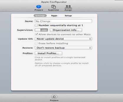
7. Click Next.
Figure 111 Installing profiles
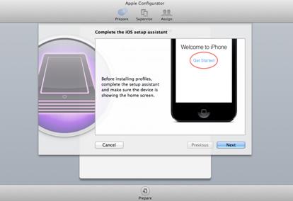
8. Select the profile h3c.com and click Next.
Figure 112 Selecting the created profile
9. Click Install.
Figure 113 Installing the profile
After the installation is complete, the Apple Configurator page displays Install Succeeded and all configuration will be deployed to iPhone 5S. When the phone finds the service it needs, it automatically joins the WLAN.
Figure 114 Installation complete
Verifying the configuration
# Verify that the phone can automatically connect to the WLAN service.
[AC] display wlan client verbose
Total number of clients: 1
MAC address : 6021-c05d-19e0
IPv4 address : 105.0.0.5
IPv6 address : N/A
Username : dongxixi
AID : 1
AP ID : 2
AP name : ap1
Radio ID : 2
SSID : dongxixi
BSSID : 70f9-6dd7-cfd0
VLAN ID : 1
Sleep count : 0
Wireless mode : 802.11gn
Channel bandwidth : 20MHz
SM power save : Enabled
SM power save mode : Static
Short GI for 20MHz : Supported
Short GI for 40MHz : Not supported
STBC RX capability : Not supported
STBC TX capability : Not supported
LDPC RX capability : Not supported
Block Ack : TID 0 In
Support HT-MCS set : 0, 1, 2, 3, 4, 5, 6, 7
Supported rates : 1, 2, 5.5, 6, 9, 11,
12, 18, 24, 36, 48, 54 Mbps
QoS mode : WMM
Listen interval : 10
RSSI : 49
Rx/Tx rate : 1/72.2 Mbps
Authentication method : Open system
Security mode : RSN
AKM mode : 802.1X
Cipher suite : CCMP
User authentication mode : 802.1X
Authorization ACL ID : N/A
Authorization user profile : N/A
Roam status : N/A
Key derivation : SHA1
PMF status : N/A
Forwarding policy name : N/A
Online time : 0days 0hours 0minutes 36seconds
FT status : Inactive
Samsung application
Network requirements
As shown in Figure 115, configure Hotspot 2.0 to enable the phone to switch from the cellular network to the wireless network.
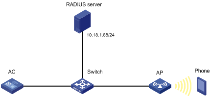
Configuration restrictions and guidelines
When you configure Hotspot 2.0, follow these restrictions and guidelines:
· Make sure you have installed certificates and created a user account on the RADIUS server, so that client authentication, authorization, and accounting can operate correctly.
· Make sure you have configured 802.1X and installed the certificate on the phone.
· For more information about AAA, see Security Configuration Guide.
Configuration procedures
Configuring the AC
1. Configure the Hotspot 2.0 policy:
# Create the Hotspot 2.0 policy 1.
[AC] wlan hotspot-policy 1
# Configure EAP-TLS authentication.
[AC-wlan-hs-1] nai-realm abc.com eap-method 6 auth-method 2 authentication 4
# Set the domain name to domain.abc.com.
[AC-wlan-hs-1] domain-name domain.abc.com
# Set the HESSID to 1232-ff23-0123, the MAC address of the AP.
[AC-wlan-hs-1] hessid 1232-ff23-0123
[AC-wlan-hs-1] quit
2. Configure 802.1X authentication and the RADIUS scheme:
# Configure the 802.1X authentication method as EAP.
[AC] dot1x authentication-method eap
# Create the RADIUS scheme imcc.
[AC] radius scheme imcc
# Set the IP address and the port number of the primary authentication server to 10.18.1.88 and 1812, respectively.
[AC-radius-imcc] primary authentication 10.18.1.88 1812
# Set the IP address and the port number of the primary accounting server to 10.18.1.88 and 1813, respectively.
[AC-radius-imcc] primary accounting 10.18.1.88 1813
# Set the shared key for the AC to exchange packets with the authentication and accounting servers to 12345678.
[AC-radius-imcc] key authentication simple 12345678
[AC-radius-imcc] key accounting simple 12345678
# Configure the AC to remove the domain name in the username sent to the RADIUS servers.
[AC-radius-imcc] user-name-format without-domain
[AC-radius-imcc] quit
3. Create the domain imc and configure the domain to use the RADIUS scheme imcc for authentication, authorization, and accounting.
[AC-isp-imc] authentication lan-access radius-scheme imcc
[AC-isp-imc] authorization lan-access radius-scheme imcc
[AC-isp-imc] accounting lan-access radius-scheme imcc
[AC-isp-imc] quit
Configuring the AP
# Create the service template service1.
[AC] wlan service-template service1
# Set the SSID to service.
[AC-wlan-st-service1] ssid service
# Bind the Hotspot 2.0 policy 1 to the service template.
[AC-wlan-st-service1] hotspot-policy 1
# Enable the RSN IE in beacons and probe responses.
[AC-wlan-st-stname] security-ie rsn
# Enable the AES-CCMP cipher suite.
[AC-wlan-st-service1] cipher-suite ccmp
# Set the authentication and key management mode to 802.1X.
[AC-wlan-st-service1] akm mode dot1x
# Set the authentication mode for WLAN clients to 802.1X.
[AC-wlan-st-service1] client-security authentication-mode dot1x
# Specify the domain imc as the authentication domain.
[AC-wlan-st-service1] dot1x domain imc
# Enable the service template.
[AC-wlan-st-service1] service-template enable
[AC-wlan-st-service1] quit
# Create the AP ap1, and specify the AP model and serial ID.
[AC] wlan ap ap1 model WA536-WW
[AC-wlan-ap-ap1] serial-id 219801A0CNC138011454
# Bind the service template service1 to radio 2 of the AP.
[AC-wlan-ap-ap1-radio-2] radio enable
[AC-wlan-ap-ap1-radio-2] service-template service1
[AC-wlan-ap-ap1-radio-2] quit
[AC-wlan-ap-ap1] quit
Configuring the RADIUS server (IMCv7)
This example was created on IMC PLAT 7.1 and IMC UAM 7.1.
To configure the IMC server:
1. Log in to the IMC platform.
2. Click the User tab.
3. Add an access device:
a. From the navigation tree, select User Access Policy > Access Device Management > Access Device.
b. On the access device configuration page, click Add.
c. On the Add Access Device page, configure the following parameters:
- Set the shared key to 12345678.
- Select or manually add the device with the IP address 10.18.1.1 (IP address of the AC).
- Use the default settings for other parameters.
d. Click OK.
Figure 116 Adding an access device

4. Add an access policy:
a. From the navigation tree, select User Access Policy > Access Policy.
b. On the access policy configuration page, click Add.
c. On the Add Access Policy page, configure the following parameters:
- Set the access policy name to 802.1X_policy.
- Select EAP-PEAP Authentication from the Certificate Type list, and from the Certificate Sub-Type list, select the certificate sub-type, which must be the same as the authentication method for the client.
- Use the default settings for other parameters.
Figure 117 Adding an access policy
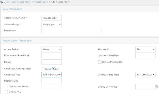
5. Add an access service:
a. From the navigation tree, select User Access Policy > Access Service.
b. On the access service configuration page, click Add.
c. On the Add Access Service page, configure the service name as 802.1X_ser, and use the 802.1X policy you have created as the default access policy.
d. Use the default settings for other parameters.
Figure 118 Adding an access service
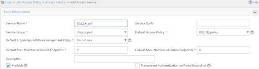
6. Add an access user:
a. From the navigation tree, select Access User > All Access Users.
b. On the access user configuration page, click Add.
c. On the Add Access User page, click Add User.
d. On the Add User window, configure the following parameters:
- Set the username to admin.
- Set the account name to admin.
- Select the 802.1X user 802.1X_ser you have configured in the Access Service area..
Figure 119 Adding an access user

Configuring the phone
|
|
IMPORTANT: · Configure the same realm name and domain for both the phone and the Hotspot 2.0 policy on the AC. · Configure the same username and password for both the phone and the RADIUS server. · Configure the same authentication type for the phone, the Hotspot 2.0 policy on the AC, and the RADIUS server. |
This example was created using Samsung S4.
To configure the phone:
1. Use a text editor to edit the Hotspot 2.0 configuration file and save it with the name cred.conf on a PC or on the phone.
realm="abc.com"
username="admin"
password="12345678"
domain="domain.abc.com"
eap=PEAP
phase2="auth=MSCHAPV2"
}
2. Save the configuration file in the root directory of the phone:
? If you edit the configuration file on a PC, use either of the following methods to import the configuration file to the phone and save it in the root directory:
- Connect the phone to a PC by using a USB cable, and save the file cred.conf in the phone.
- Send an email to the phone with the file cred.conf attached and save the file in the phone.
? If you edit the file on the phone by using a text editor, save it in the root directory of the phone.
3. Turn on WLAN on the phone.
Figure 120 Turning on WLAN
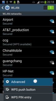
4. Click Advanced.
Figure 121 Configuring advanced WLAN settings
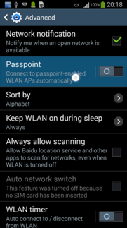
5. On the Advanced page, enable Passpoint.
Figure 122 Enabling Passpoint
Verifying the configuration
# Verify that the phone can automatically connect to the WLAN service.
[AC] display wlan client verbose
Total number of clients: 1
MAC address : 000f-e265-6400
IPv4 address : 10.1.1.114
IPv6 address : 2001::1234:5678:0102:0304
Username : admin
AP ID : 1
AP name : ap1
Radio ID : 1
SSID : service
BSSID : 0026-3e08-1150
VLAN ID : 1
Power save mode : Active
Wireless mode : 802.11gn
Channel bandwidth : 20MHz
SM power save : Disabled
Short GI for 20MHz : Not supported
Short GI for 40MHz : Supported
Support MCS set : 0, 1, 2, 3, 4, 5, 6, 7, 8, 9, 10
Block Ack (TID 0) : In
QoS mode : N/A
Listen interval : 10
RSSI : 62
Rx/Tx rate : 130/11 Mbps
Authentication method : Open system
Hotspot 2.0 configuration examples (for version 2)
Network requirements
As shown in Figure 123, configure Hotspot 2.0 to enable the phone to switch from the cellular network to the wireless network.
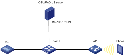
Configuration restrictions and guidelines
When you configure Hotspot 2.0, follow these restrictions and guidelines:
· For more information about AAA, see Security Configuration Guide.
· Before uploading the OSU server icon, make sure the icon file is in the root directory where the version files are saved. You can use FTP or TFTP to transmit the icon file.
Configuration procedures
1. Configure the OSU server:
# Create OSU server 1.
<AC> system-view
[AC] wlan osu-provider 1
# Set the name for the OSU server to osu_test.
[AC-wlan-osu-1] friendly-name osu_test lang-code eng
# Specify a URI for the OSU server.
[AC-wlan-osu-1] uri https://192.168.1.23:8088/service
# Set the protocol for clients to communicate with the OSU server to SOAP-XML SPP.
[AC-wlan-osu-1] method 1
# Specify an icon for the OSU server.
[AC-wlan-osu-1] icon-file test.png lang-code eng icon-type png
# Configure a description for the OSU server.
[AC-wlan-osu-1] description "The OSU provider." lang-code eng
# Configure the NAI.
[AC-wlan-osu-1] nai example.com
[AC-wlan-osu-1] quit
2. Configure a Hotspot 2.0 policy:
# Create Hotspot 2.0 policy 1.
[AC] wlan hotspot-policy 1
# Specify the authentication type for NAI realm example.com.
[AC-wlan-hs-1] nai-realm example.com eap-method 5 auth-method 2 authentication 4
# Set the access network type to Wildcard.
[AC-wlan-hs-1] network-type 15
# Set the OI to 80F62E and add the OI to beacons.
[AC-wlan-hs-1] roam-oi 80F62E in-beacon
# Set the domain name to domain.com.
[AC-wlan-hs-1] domain-name domain.com
# Set the availability to 1 for both IPv4 addresses and IPv6 addresses.
[AC-wlan-hs-1] ip-type ipv4 1 ipv6 1
# Set the SSID for online signup services to osu-ssid.
[AC-wlan-hs-1] osu-ssid osu-ssid
# Bind OSU server 1 to Hotspot 2.0 policy 1.
[AC-wlan-hs-1] osu-provider 1
[AC-wlan-hs-1] quit
# Upload the specified OSU server icons if a specified icon file changes.
[AC] wlan hotspot osu-icon upload
3. Configure a service template for online signup services:
# Create service template osu.
[AC] wlan service-template osu
# Set the SSID to osu-ssid.
[AC-wlan-st-osu] ssid osu-ssid
# Enable the service template.
[AC-wlan-st-osu] service-template enable
[AC-wlan-st-osu] quit
4. Configure 802.1X authentication and the RADIUS server:
# Configure the 802.1X authentication method as EAP.
[AC] dot1x authentication-method eap
# Create RADIUS scheme imcc.
# Set the IP address and the port number of the primary authentication server to 192.168.1.23 and 1813, respectively.
[AC-radius-imcc] primary authentication 192.168.1.23 1812
# Set the IP address and the port number of the primary accounting server to 192.168.1.23 and 1813, respectively.
[AC-radius-imcc] primary accounting 192.168.1.23 1813
# Set the shared key for the AC to exchange packets with the authentication and accounting server to 12345678.
[AC-radius-imcc] key authentication simple 12345678
[AC-radius-imcc] key accounting simple 12345678
# Configure the AC to remove the domain name in the username sent to the RADIUS servers.
[AC-radius-imcc] user-name-format without-domain
[AC-radius-imcc] quit
5. Configure ISP domain:
# Create domain imc and configure the domain to use RADIUS scheme imcc for authentication, authorization, and accounting.
[AC-isp-imc] authentication lan-access radius-scheme imcc
[AC-isp-imc] authorization lan-access radius-scheme imcc
[AC-isp-imc] accounting lan-access radius-scheme imcc
[AC-isp-imc] quit
6. Configure a service template for wireless services:
# Create service template stname.
[AC] wlan service-template stname
# Set the SSID to service.
[AC-wlan-st-stname] ssid service
# Bind Hotspot 2.0 policy 1 to the service template.
[AC-wlan-st-stname] hotspot-policy 1
# Enable the RSN IE in beacons and probe responses.
[AC-wlan-st-stname] security-ie rsn
# Enable the AES-CCMP cipher suite.
[AC-wlan-st-stname] cipher-suite ccmp
[AC-wlan-st-stname] akm mode dot1x
# Set the authentication mode for WLAN clients to 802.1X.
[AC-wlan-st-stname] client-security authentication-mode dot1x
# Specify the domain imc as the authentication domain.
[AC-wlan-st-stname] dot1x domain imc
# Enable the service template.
[AC-wlan-st-stname] service-template enable
[AC-wlan-st-stname] quit
7. Configure the AP:
# Create AP ap1, and specify the AP model and serial ID.
[AC] wlan ap ap1 model WA536-WW
[AC-wlan-ap-ap1] serial-id 210235A1BSC123000050
# Set a venue name for the AP.
[AC-wlan-ap-ap1] venue name "H3C lab" lang-code eng
# Bind service template stname to radio 2 of the AP.
[AC-wlan-ap-ap1] radio 2
[AC-wlan-ap-ap1-radio-2] radio enable
[AC-wlan-ap-ap1-radio-2] service-template stname
[AC-wlan-ap-ap1-radio-2] service-template osu
[AC-wlan-ap-ap1-radio-2] quit
[AC-wlan-ap-ap1] quit
Verifying the configuration
# Verify that the OSU server icon has been loaded.
[AC] display wlan hotspot uploaded-osu-icon
Total number of icons: 1
Icon name Icon type
--------------------------------------------------------------------------------
test.png png
# Verify that the phone can automatically connect to the WLAN service.
[AC] display wlan client verbose
Total number of clients: 1
MAC address : d022-bee8-a267
IPv4 address : 192.168.1.52
IPv6 address : N/A
Username : abcd
AID : 2
AP ID : 1
AP name : ap1
Radio ID : 2
SSID : service
BSSID : 5866-ba74-e790
VLAN ID : 1
Sleep count : 37
Wireless mode : 802.11gn
Channel bandwidth : 20MHz
SM power save : Disabled
Short GI for 20MHz : Supported
Short GI for 40MHz : Not supported
STBC RX capability : Supported
STBC TX capability : Not supported
LDPC RX capability : Not supported
Block Ack : TID 0 Both
TID 2 Out
Supported HT MCS set : 0, 1, 2, 3, 4, 5, 6, 7
Supported rates : 1, 2, 5.5, 6, 9, 11,
12, 18, 24, 36, 48, 54 Mbps
QoS mode : WMM
Listen interval : 10
RSSI : 45
Rx/Tx rate : 72.2/72.2 Mbps
Authentication method : Open system
Security mode : RSN
AKM mode : 802.1X
Cipher suite : CCMP
User authentication mode : 802.1X
Authorization ACL ID : N/A
Authorization user profile : N/A
Roam status : N/A
Key derivation : SHA1
PMF status : N/A
Forwarding policy name : N/A
Online time : 0days 0hours 1minutes 29seconds
FT status : Inactive
Configuring WLAN RRM
Overview
WLAN Radio Resource Management (RRM) provides an intelligent and scalable radio management solution. RRM enables the AC to monitor its associated radios and perform radio resource monitoring, dynamic frequency selection (DFS), and transmit power control (TPC). This allows a WLAN to adapt to environment changes and maintain the optimal radio resource condition.
Dynamic frequency selection
Two adjacent radios on the same channel might cause signal collision, and other radio sources such as radar signals and microwave ovens might interfere with the operation of radios. DFS can solve these problems.
With DFS, the AC selects an optimal channel for each radio in real time to avoid co-channel interference and interference from other radio sources.
The following factors will trigger DFS:
· Error code rate—Physical layer error code rate and CRC error rate. CRC error rate shows the proportion of packets with CRC errors among all 802.11 packets.
· Interference rate—Proportion of interference packets among all data packets. Interference packets are packets destined for other radios.
· Retransmission count—Data retransmissions caused by failure to receive ACK messages.
· Radar signal—Radar signals detected on the current channel. In this case, the AC selects a new channel and immediately notifies the radio to change its working channel.
The AC uses the following procedure to perform DFS for a radio:
1. Detects the current channel and selects an optimal channel when the CRC error threshold, the interference threshold, or the system-defined retransmission threshold is reached on the current channel.
2. Compares the quality between the current channel and the optimal channel. The radio does not use the optimal channel until the quality gap between the two channels exceeds the tolerance level.
Figure 124 shows a DFS example. When the quality of the channels for BSS 1, BSS 3, and BSS 5 reaches a DFS threshold, the AC selects an optimal channel for each of them. This ensures wireless service quality.
Figure 124 Dynamic frequency selection
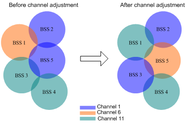
Transmit power control
TPC enables the AC to dynamically control access point transmit power based on real-time WLAN conditions. It can achieve desired RF coverage while avoiding channel interference between radios.
The AC maintains a neighbor report for each radio on its associated APs to record information about other radios detected by this radio. The AC can manage only radios associated with the AC.
The AC uses the following procedure to perform TPC for a radio:
1. Determines whether the number of manageable radios detected by this radio reaches the adjacency factor.
If the number does not reach the adjacency factor, the radio uses the maximum transmit power.
If the number reaches the adjacency factor, the AC goes to step 2.
2. Ranks the radio's RSSIs stored in neighbor reports of other radios in descending order.
3. Compares the RSSI specified by the adjacency factor with the power adjustment threshold and takes one of the following actions:
? Decreases the radio's transmit power when the RSSI rises above the threshold.
? Increases the radio's transmit power when the RSSI drops below the threshold.
As shown in Figure 125, each AP has only one radio enabled. Before AP 4 joins, the radios use the maximum transmit power because the number of manageable radios detected by each radio has not reached adjacency factor 3. After AP 4 joins, the AC uses TPC to adjust the transmit powers for all radios because the number of manageable radios detected by each radio has reached adjacency factor 3.
Figure 125 Transmit power control
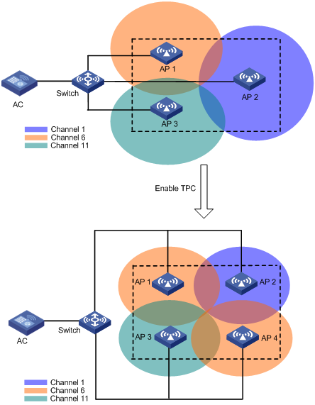
Spectrum management
Spectrum management is 802.11h compliant. It is used on 5 GHz WLANs to ensure that clients meet the regulatory requirements for operation in the 5 GHz band. It enables an AP to notify its associated clients of the allowed maximum transmit power. The AP can deny the association request from a client if the power and channel of the client do not meet the regulatory requirements.
Configuration restrictions and guidelines
The priorities for the configuration in AP view, AP group view, and global configuration view are in descending order.
WLAN RRM configuration task list
|
Tasks at a glance |
|
· (Optional.) Configuring DFS trigger parameters · (Required.) Choose one of the following tasks: ? Configuring periodic auto-DFS ? Configuring scheduled auto-DFS · (Optional.) Configuring an RRM holddown group |
|
· (Optional.) Setting the TPC mode · (Optional.) Configuring TPC trigger parameters · (Optional.) Setting the minimum transmit power · (Required.) Choose either of the following tasks: ? Configuring periodic auto-TPC · (Optional.) Configuring an RRM holddown group |
|
Configuring spectrum management: · (Required.) Enabling spectrum management · (Optional.) Setting the power constraint mode · (Optional.) Setting the channel switch mode · (Optional.) Setting the transmit power capability match mode · (Optional.) Setting the channel capability match mode |
|
(Optional.) Configuring a radio baseline |
|
(Optional.) Enabling radio scanning |
|
(Optional.) Enabling SNMP notifications for WLAN RRM |
Configuring DFS
The AC supports the following DFS methods:
· Periodic auto-DFS—The AC automatically performs DFS for a radio at the channel calibration interval.
· Scheduled auto-DFS—The AC performs DFS at the specified time in a time range. Use this method when interference is severe to avoid affecting ongoing wireless services.
· On-demand DFS—The AC waits for a channel calibration interval and then performs DFS for all radios. You must perform this task every time you want the AC to perform DFS for radios.
Configuration restrictions and guidelines
For DFS to work, configure the AC to automatically select a channel for a radio and not lock the channel by using the channel auto unlock command. For more information about the channel { channel-number | auto { lock | unlock } } command, see WLAN Command Reference.
Configuring DFS trigger parameters
|
|
IMPORTANT: As a best practice for accurate channel adjustment, configure the same DFS trigger parameters for all radios enabled with DFS. |
Configuring DFS trigger parameters in RRM view
|
Step |
Command |
Remarks |
|
1. Enter system view. |
system-view |
N/A |
|
2. Create an AP and enter AP view. |
wlan ap ap-name [ model model-name ] |
Specify the AP model when you create an AP. |
|
3. Enter radio view. |
radio radio-id |
N/A |
|
4. Enter RRM view. |
rrm |
N/A |
|
5. Set the CRC error threshold. |
crc-error-threshold percent |
By default, the configuration in AP group RRM view is used. |
|
6. Set the interference threshold. |
interference-threshold percent |
By default, the configuration in AP group RRM view is used. |
|
7. Set the tolerance level. |
tolerance-level percent |
By default, the configuration in AP group RRM view is used. |
Configuring DFS trigger parameters in AP group RRM view
|
Step |
Command |
Remarks |
|
1. Enter system view. |
system-view |
N/A |
|
2. Enter AP group view. |
wlan ap-group group-name |
N/A |
|
3. Enter AP model view. |
ap-model ap-model |
N/A |
|
4. Enter radio view. |
radio radio-id |
N/A |
|
5. Enter RRM view. |
rrm |
N/A |
|
6. Set the CRC error threshold. |
crc-error-threshold percent |
By default, the CRC error threshold is 20. |
|
7. Set the interference threshold. |
interference-threshold percent |
By default, the interference threshold is 50. |
|
8. Set the tolerance level. |
tolerance-level percent |
By default, the tolerance level is 20. |
Configuring periodic auto-DFS
Configuring periodic auto-DFS in RRM view
|
Step |
Command |
Remarks |
|
1. Enter system view. |
system-view |
N/A |
|
2. (Optional.) Set the channel calibration interval. |
wlan rrm calibration-channel interval minutes |
By default, the channel calibration interval is 8 minutes. |
|
3. Create an AP and enter AP view. |
wlan ap ap-name [ model model-name ] |
N/A |
|
4. Enter radio view. |
radio radio-id |
N/A |
|
5. Enter RRM view. |
rrm |
N/A |
|
6. Enable auto-DFS. |
calibrate-channel self-decisive enable |
By default, the configuration in AP group view RRM is used. |
|
7. Set the auto-DFS mode to periodic. |
calibrate-channel mode periodic |
By default, the configuration in AP group RRM view is used. |
Configuring periodic auto-DFS in AP group RRM view
|
Step |
Command |
Remarks |
|
1. Enter system view. |
system-view |
N/A |
|
2. (Optional.) Set the channel calibration interval. |
wlan rrm calibration-channel interval minutes |
By default, the channel calibration interval is 8 minutes. |
|
3. Enter AP group view. |
wlan ap-group group-name |
N/A |
|
4. Enter AP model view. |
ap-model ap-model |
N/A |
|
5. Enter radio view. |
radio radio-id |
N/A |
|
6. Enter RRM view. |
rrm |
N/A |
|
7. Enable auto-DFS. |
calibrate-channel self-decisive enable |
By default, auto-DFS is disabled. |
|
8. Set the auto-DFS mode to periodic. |
calibrate-channel mode periodic |
By default, the auto-DFS mode is periodic. |
Configuring scheduled auto-DFS
To configure scheduled auto-DFS, you must create a time range during which the AC collects statistics to generate channel reports and neighbor reports.
Configuring scheduled auto-DFS in RRM view
|
Step |
Command |
Remarks |
|
1. Enter system view. |
system-view |
N/A |
|
2. Create a time range. |
time-range time-range-name { start-time to end-time days [ from time1 date1 ] [ to time2 date2 ] | from time1 date1 [ to time2 date2 ] | to time2 date2 } |
By default, no time range exists. |
|
3. Create a job and enter its view. |
scheduler job job-name |
By default, no job exists. |
|
4. Assign commands to the job. |
command 1 system-view command 2 wlan ap ap-name [ model model-name ] command 3 radio radio-id command 4 rrm command 5 calibrate-channel pronto |
By default, no command is assigned to a job. |
|
5. Return to system view. |
quit |
N/A |
|
6. Create a schedule and enter its view. |
scheduler schedule schedule-name |
By default, no schedule exists. |
|
7. Assign a job to the schedule. |
job job-name |
By default, no job is assigned to a schedule. |
|
8. Assign a user role to the schedule. |
user-role role-name |
By default, the user role of the schedule creator is assigned to the schedule. |
|
9. Specify an execution date and time for the schedule. |
time at time date |
Execute one of the three commands. By default, no execution time is specified for a schedule. |
|
10. Specify one or more execution days and the execution time for the schedule. |
time once at time [ month-date month-day | week-day week-day&<1-7> ] |
|
|
11. Specify the delay time for executing the schedule. |
time once delay time |
|
|
12. Return to system view. |
quit |
N/A |
|
13. Enter AP view. |
wlan ap ap-name [ model model-name ] |
N/A |
|
14. Enter radio view. |
radio radio-id |
N/A |
|
15. Enter RRM view. |
rrm |
N/A |
|
16. Enable auto-DFS. |
calibrate-channel self-decisive enable |
By default, the configuration in AP group RRM view is used. |
|
17. Set the auto-DFS mode to scheduled. |
calibrate-channel mode scheduled |
By default, the configuration in AP group RRM view is used. |
|
18. Specify a time range for channel monitoring. |
calibrate-channel monitoring time-range time-range-name |
By default, the configuration in AP group RRM view is used. |
Configuring scheduled auto-DFS in AP group RRM view
|
Step |
Command |
Remarks |
|
1. Enter system view. |
system-view |
N/A |
|
2. Create a time range. |
time-range time-range-name { start-time to end-time days [ from time1 date1 ] [ to time2 date2 ] | from time1 date1 [ to time2 date2 ] | to time2 date2 } |
By default, no time range exists. |
|
3. Create a job and enter its view. |
scheduler job job-name |
By default, no job exists. |
|
4. Assign commands to the job. |
command 1 system-view command 2 wlan ap-group group-name command 3 ap-model ap-model command 4 radio radio-id command 5 rrm command 6 calibrate-channel pronto |
By default, no command is assigned to a job. |
|
5. Return to system view. |
quit |
N/A |
|
6. Create a schedule and enter its view. |
scheduler schedule schedule-name |
By default, no schedule exists. |
|
7. Assign a job to the schedule. |
job job-name |
By default, no job is assigned to a schedule. |
|
8. Assign a user role to the schedule. |
user-role role-name |
By default, the user role of the schedule creator is assigned to the schedule. |
|
9. Specify an execution date and time for the schedule. |
time at time date |
Execute one of the three commands. By default, no execution time is specified for a schedule. |
|
10. Specify one or more execution days and the execution time for the schedule. |
time once at time [ month-date month-day | week-day week-day&<1-7> ] |
|
|
11. Specify the delay time for executing the schedule. |
time once delay time |
|
|
12. Return to system view. |
quit |
N/A |
|
13. Enter AP group view. |
wlan ap-group group-name |
N/A |
|
14. Enter AP model view. |
ap-model ap-model |
N/A |
|
15. Enter radio view. |
radio radio-id |
N/A |
|
16. Enter RRM view. |
rrm |
N/A |
|
17. Enable auto-DFS. |
calibrate-channel self-decisive enable |
By default, auto-DFS is disabled. |
|
18. Set the auto-DFS mode to scheduled. |
calibrate-channel mode scheduled |
By default, the auto-DFS mode is periodic. |
|
19. Specify a time range for channel monitoring. |
calibrate-channel monitoring time-range time-range-name |
By default, no time range is specified for channel monitoring. |
Configuring on-demand DFS
|
|
IMPORTANT: This feature consumes system resources. Use it with caution. |
To configure on-demand DFS:
|
Step |
Command |
Remarks |
|
1. Enter system view. |
system-view |
N/A |
|
2. Enable on-demand DFS for radios of all APs. |
wlan calibrate-channel pronto ap all |
N/A |
|
3. (Optional.) Set the channel calibration interval. |
wlan rrm calibration-channel interval minutes |
By default, the channel calibration interval is 8 minutes. |
Configuring an RRM holddown group
To prevent frequent channel adjustments from affecting wireless services, you can add radios to an RRM holddown group. Each time the channel of a radio in the RRM holddown group changes, the system starts a channel holddown timer for the radio. The channel for the radio does not change until the channel holddown timer expires.
If you execute on-demand DFS, the system performs DFS when the calibration interval expires regardless of whether the channel holddown timer expires.
To configure an RRM holddown group:
|
Step |
Command |
Remarks |
|
1. Enter system view. |
system-view |
N/A |
|
2. Create an RRM holddown group and enter its view. |
wlan rrm-calibration-group group-id |
By default, no RRM holddown group exists. |
|
3. (Optional.) Set a description for the RRM holddown group. |
description text |
By default, no description is set for the RRM holddown group. |
|
4. Add a radio to the RRM holddown group. |
ap ap-name radio radio-id |
By default, no radio exists in the RRM holddown group. |
|
5. (Optional.) Set the channel holddown time. |
channel holddown-time minutes |
By default, the channel holddown time is 720 minutes. |
Configuring TPC
The AC supports the following TPC methods:
· Periodic auto-TPC—The AC automatically performs TPC for a radio at the power calibration interval.
· On-demand TPC—The AC waits for a power calibration interval and then performs TPC for all radios. You must perform this task every time you want the AC to perform TPC for radios.
Configuration restrictions and guidelines
Make sure the power lock feature is disabled before configuring TPC. For more information about power lock, see "Configuring radio management."
Setting the TPC mode
The AC supports the density, coverage, and custom TPC modes. To avoid interference among APs, use the density mode. To increase signal coverage performance, use the coverage mode. If these two modes cannot meet your network requirements, use the custom mode to customize power adjustment settings.
In either density or coverage mode, power adjustment settings are defined by the system and cannot be changed.
Setting the TPC mode in RRM view
|
Step |
Command |
Remarks |
|
1. Enter system view. |
system-view |
N/A |
|
2. Create an AP and enter AP view. |
wlan ap ap-name [ model model-name ] |
N/A |
|
3. Enter radio view. |
radio radio-id |
N/A |
|
4. Enter RRM view. |
rrm |
N/A |
|
5. Set the TPC mode. |
calibrate-power mode { coverage | custom | density } |
By default, the configuration in AP group RRM view is used. |
Setting the TPC mode in AP group RRM view
|
Step |
Command |
Remarks |
|
1. Enter system view. |
system-view |
N/A |
|
2. Enter AP group view. |
wlan ap-group group-name |
N/A |
|
3. Enter AP model view. |
ap-model ap-model |
N/A |
|
4. Enter radio view. |
radio radio-id |
N/A |
|
5. Enter RRM view. |
rrm |
N/A |
|
6. Set the TPC mode. |
calibrate-power mode { coverage | custom | density } |
By default, the TPC mode is custom. |
Configuring TPC trigger parameters
|
|
IMPORTANT: As a best practice for accurate power adjustment, configure the same TPC trigger parameters for all radios enabled with TPC. |
The adjacency factor and power adjustment threshold determine TPC for a radio. The adjacency factor defines the quantity of manageable detected radios that trigger TPC and the ranking of the RSSI used for comparison with the power adjustment threshold. Set an appropriate adjacency factor as needed.
Configuring TPC trigger parameters in RRM view
|
Step |
Command |
Remarks |
|
1. Enter system view. |
system-view |
N/A |
|
2. Create an AP and enter AP view. |
wlan ap ap-name [ model model-name ] |
N/A |
|
3. Enter radio view. |
radio radio-id |
N/A |
|
4. Enter RRM view. |
rrm |
N/A |
|
5. Set the adjacency factor. |
adjacency-factor neighbor |
By default, the configuration in AP group RRM view is used. |
|
6. Set the power adjustment threshold. |
calibrate-power threshold value |
By default, the configuration in AP group RRM view is used. |
Configuring TPC trigger parameters in AP group RRM view
|
Step |
Command |
Remarks |
|
1. Enter system view. |
system-view |
N/A |
|
2. Enter AP group view. |
wlan ap-group group-name |
N/A |
|
3. Enter AP model view. |
ap-model ap-model |
N/A |
|
4. Enter radio view. |
radio radio-id |
N/A |
|
5. Enter RRM view. |
rrm |
N/A |
|
6. Set the adjacency factor. |
adjacency-factor neighbor |
By default, the adjacency factor is 3. |
|
7. Set the power adjustment threshold. |
calibrate-power threshold value |
By default, the power adjustment threshold is 65 dBm. |
Setting the minimum transmit power
This feature ensures that a radio can still be detected after TPC is performed.
Setting the minimum transmit power in RRM view
|
Step |
Command |
Remarks |
|
1. Enter system view. |
system-view |
N/A |
|
2. Create an AP and enter AP view. |
wlan ap ap-name [ model model-name ] |
N/A |
|
3. Enter radio view. |
radio radio-id |
N/A |
|
4. Enter RRM view. |
rrm |
N/A |
|
5. Set the minimum transmit power. |
calibrate-power min tx-power |
By default, the configuration in AP group RRM view is used. |
Setting the minimum transmit power in AP group RRM view
|
Step |
Command |
Remarks |
|
1. Enter system view. |
system-view |
N/A |
|
2. Enter AP group view. |
wlan ap-group group-name |
N/A |
|
3. Enter AP model view. |
ap-model ap-model |
N/A |
|
4. Enter radio view. |
radio radio-id |
N/A |
|
5. Enter RRM view. |
rrm |
N/A |
|
6. Set the minimum transmit power. |
calibrate-power min tx-power |
By default, the minimum transmit power is 1 dBm. |
Configuring periodic auto-TPC
Configuring periodic auto-TPC in RRM view
|
Step |
Command |
Remarks |
|
1. Enter system view. |
system-view |
N/A |
|
2. (Optional.) Set the power calibration interval. |
wlan rrm calibration-power interval minutes |
By default, the power calibration interval is 8 minutes. |
|
3. Create an AP and enter AP view. |
wlan ap ap-name [ model model-name ] |
N/A |
|
4. Enter radio view. |
radio radio-id |
N/A |
|
5. Enter RRM view. |
rrm |
N/A |
|
6. Enable periodic auto-TPC. |
calibrate-power self-decisive enable |
By default, the configuration in AP group RRM view is used. |
Configuring periodic auto-TPC in AP group RRM view
|
Step |
Command |
Remarks |
|
1. Enter system view. |
system-view |
N/A |
|
2. (Optional.) Set the power calibration interval. |
wlan rrm calibration-power interval minutes |
By default, the power calibration interval is 8 minutes. |
|
3. Enter AP group view. |
wlan ap-group group-name |
N/A |
|
4. Enter AP model view. |
ap-model ap-model |
N/A |
|
5. Enter radio view. |
radio radio-id |
N/A |
|
6. Enter RRM view. |
rrm |
N/A |
|
7. Enable periodic auto-TPC. |
calibrate-power self-decisive enable |
By default, periodic auto-TPC is disabled. |
Configuring on-demand TPC
|
|
IMPORTANT: This feature consumes system resources. Use it with caution. |
|
Step |
Command |
Remarks |
|
1. Enter system view. |
system-view |
N/A |
|
2. Enable on-demand TPC for radios of all APs. |
wlan calibrate-power pronto ap all |
N/A |
|
3. (Optional.) Set the power calibration interval. |
wlan rrm calibration-power interval minutes |
By default, the power calibration interval is 8 minutes. |
Configuring an RRM holddown group
To prevent frequent power adjustments from affecting wireless services, you can add radios to an RRM holddown group. Each time the power of a radio in the RRM holddown group changes, the system starts a power holddown timer for the radio. The power for the radio does not change until the power holddown timer expires.
If you execute on-demand DFS, the system performs DFS when the calibration interval expires regardless of whether the power holddown timer expires.
To configure an RRM holddown group:
|
Step |
Command |
Remarks |
|
1. Enter system view. |
system-view |
N/A |
|
2. Create an RRM holddown group and enter its view. |
wlan rrm-calibration-group group-id |
By default, no RRM holddown group exists. |
|
3. (Optional.) Set a description for the RRM holddown group. |
description text |
By default, no description is set for the RRM holddown group. |
|
4. Add a radio to the RRM holddown group. |
ap ap-name radio radio-id |
By default, no radio exists in the RRM holddown group. |
|
5. (Optional.) Set the power holddown time. |
power holddown-time minutes |
By default, the power holddown time is 60 minutes. |
Configuring spectrum management
Enabling spectrum management
This feature is available only on 5 GHz radios.
Enabling spectrum management in radio view
|
Step |
Command |
Remarks |
|
1. Enter system view. |
system-view |
N/A |
|
2. Create an AP and enter AP view. |
wlan ap ap-name [ model model-name ] |
N/A |
|
3. Enter radio view. |
radio radio-id |
N/A |
|
4. Enable spectrum management. |
spectrum-management enable |
By default, the configuration in AP group radio view is used. |
Enabling spectrum management in AP group radio view
|
Step |
Command |
Remarks |
|
1. Enter system view. |
system-view |
N/A |
|
2. Create an AP group and enter AP group view. |
wlan ap-group group-name |
N/A |
|
3. Specify an AP model. |
ap-model ap-model |
N/A |
|
4. Enter radio view. |
radio radio-id |
N/A |
|
5. Enable spectrum management. |
spectrum-management enable |
By default, spectrum management is disabled. |
Setting the power constraint mode
This feature is available only on 5 GHz radios.
This feature enables a radio to restrict the transmit power of its associated clients to avoid interference to other wireless devices. Upon receiving a beacon frame or probe response that contains the power constraint value from the radio, a client uses its new local maximum transmit power to transmit traffic. The new local maximum transmit power is the maximum transmit power level specified for the channel minus the power constraint value.
You can set the following power constraint modes for a radio:
· Manual—You specify a power constraint value.
· Auto—The radio automatically calculates the power constraint value.
Setting the power constraint mode in radio view
|
Step |
Command |
Remarks |
|
1. Enter system view. |
system-view |
N/A |
|
2. Create an AP and enter AP view. |
wlan ap ap-name [ model model-name ] |
N/A |
|
3. Enter radio view. |
radio radio-id |
N/A |
|
4. Set the power constraint mode. |
power-constraint mode { auto [ anpi-interval anpi-interval-value ] | manual power-constraint } |
By default, the configuration in AP group view radio is used. Power constraint takes effect only when you enable spectrum management or radio resource measurement. For more information about radio resource management, see "Configuring WLAN radio resource management." |
Setting the power constraint mode in AP group radio view
|
Step |
Command |
Remarks |
|
1. Enter system view. |
system-view |
N/A |
|
2. Create an AP group and enter AP group view. |
wlan ap-group group-name |
N/A |
|
3. Specify an AP model. |
ap-model ap-model |
N/A |
|
4. Enter radio view. |
radio radio-id |
N/A |
|
5. Set the power constraint mode. |
power-constraint mode { auto [ anpi-interval anpi-interval-value ] | manual power-constraint } |
By default, the power constraint mode is auto. Power constraint takes effect only when you enable spectrum management or radio resource measurement. For more information about radio resource management, see "Configuring WLAN radio resource management." |
Setting the channel switch mode
This feature enables a radio to send a channel switch announcement to the associated clients when the radio is changing to a new channel. The announcement contains the new channel number and information about whether the clients can continue sending frames.
Setting the channel switch mode in radio view
|
Step |
Command |
Remarks |
|
1. Enter system view. |
system-view |
N/A |
|
2. Create an AP and enter AP view. |
wlan ap ap-name [ model model-name ] |
N/A |
|
3. Enter radio view. |
radio radio-id |
N/A |
|
4. Set the channel switch mode. |
channel-switch mode { continuous | suspend } |
By default, the configuration in AP group radio view is used. |
Setting the channel switch mode in AP group radio view
|
Step |
Command |
Remarks |
|
1. Enter system view. |
system-view |
N/A |
|
2. Create an AP group and enter AP group view. |
wlan ap-group group-name |
N/A |
|
3. Specify an AP model. |
ap-model ap-model |
N/A |
|
4. Enter radio view. |
radio radio-id |
N/A |
|
5. Set the channel switch mode. |
channel-switch mode { continuous | suspend } |
By default, the channel switch mode is suspend. Online clients stop sending frames during channel switch. |
Setting the transmit power capability match mode
This feature allows clients to associate with a radio based on the predefined match criteria. Transmit power capability refers to the minimum and maximum powers with which a client and a radio can transmit frames in the current channel. The device supports the following client power capability match modes:
· All—A client is allowed to associate with a radio only when each of its transmit power capabilities matches each of the radio's transmit power capabilities.
· None—Client transmit power capabilities are not checked.
· Partial—A client is allowed to associate with a radio as long as one of its transmit power capabilities matches any transmit power capabilities of the radio.
Setting the transmit power capability match mode in radio view
|
Step |
Command |
Remarks |
|
1. Enter system view. |
system-view |
N/A |
|
2. Create an AP and enter AP view. |
wlan ap ap-name [ model model-name ] |
N/A |
|
3. Enter radio view. |
radio radio-id |
N/A |
|
4. Set the transmit power capability match mode. |
power-capability mode { all | none | partial } |
By default, the configuration in AP group radio view is used. The transmit power capability match mode takes effect only when you enable spectrum management or radio resource measurement. For more information about radio resource management, see "Configuring WLAN radio resource management." |
Setting the transmit power capability match mode in AP group radio view
|
Step |
Command |
Remarks |
|
1. Enter system view. |
system-view |
N/A |
|
2. Create an AP group and enter AP group view. |
wlan ap-group group-name |
N/A |
|
3. Specify an AP model. |
ap-model ap-model |
N/A |
|
4. Enter radio view. |
radio radio-id |
N/A |
|
5. Set the power capability match mode. |
power-capability mode { all | none | partial } |
By default, client transmit power capabilities are not checked. The transmit power capability match mode takes effect only when you enable spectrum management or radio resource measurement. For more information about radio resource management, see "Configuring WLAN radio resource management." |
Setting the channel capability match mode
This feature is available only on 5 GHz radios.
This feature allows clients to associate with a radio based on the predefined match criteria. Channel capability refers to the channels a client and a radio each support. The device provides the following client channel capability match modes:
· All—A client is allowed to associate with a radio only when each of its supported channels match each of the radio's supported channels.
· None—Client channel capabilities are not checked.
· Partial—A client is allowed to associate with a radio as long as one of its supported channels matches any supported channels of the radio.
Setting the client channel capability match mode in radio view
|
Step |
Command |
Remarks |
|
1. Enter system view. |
system-view |
N/A |
|
2. Create an AP and enter AP view. |
wlan ap ap-name [ model model-name ] |
N/A |
|
3. Enter radio view. |
radio radio-id |
N/A |
|
4. Set the client channel capability match mode. |
power-capability mode { all | none | partial } |
By default, the configuration in AP group radio view is used. |
Setting the client channel capability match mode in AP group radio view
|
Step |
Command |
Remarks |
|
1. Enter system view. |
system-view |
N/A |
|
2. Create an AP group and enter AP group view. |
wlan ap-group group-name |
N/A |
|
3. Specify an AP model. |
ap-model ap-model |
N/A |
|
4. Enter radio view. |
radio radio-id |
N/A |
|
5. Set the channel capability match mode. |
power-capability mode { all | none | partial } |
By default, client channel capabilities are not checked. |
Configuring a radio baseline
A radio baseline saves the working channel, transmit rate, and other radio attributes for radios. You can create a radio baseline by saving the current radio settings and apply the baseline to use these settings as needed.
A radio baseline is saved in a .csv file in the file system on the AC.
A radio baseline cannot be applied to a radio when one of the following conditions is met:
· The radio is down.
· No service template is bound to the radio or the bound service template is disabled.
· The channel in the baseline is illegal.
· The radio uses a manually specified channel.
· The working channel or the transmit power of the radio is locked.
· The channel or power holddown timer for the radio has not expired.
· The channel in the baseline does not match the specified channel gap.
· The transmit power in the baseline is lower than the specified minimum transmit power for the radio.
· The transmit power in the baseline is higher than the specified maximum transmit power for the radio.
· The radio mode, location identifier, or bandwidth in the baseline does not match the radio mode, location identifier, or bandwidth of the radio.
To configure a radio baseline:
|
Step |
Command |
Remarks |
|
1. Enter system view. |
system-view |
N/A |
|
2. Create a radio baseline by saving the current radio settings. |
wlan rrm baseline save name baseline-name { ap ap-name radio radio-id | ap-group group-name ap-model ap-model radio radio-id | global } |
N/A |
|
3. Apply the baseline. |
wlan rrm baseline apply name baseline-name |
N/A |
|
4. (Optional.) Delete a radio baseline. |
wlan rrm baseline remove name baseline-name |
N/A |
Enabling radio scanning
This feature enables APs to scan the WLAN environment and report collected statistics to the AC at the specified interval. The AC uses the statistics to generate channel reports and neighbor reports.
To view the channel reports and neighbor reports, use the display wlan rrm-status ap command.
If you have configured periodic auto-DFS, scheduled auto-DFS, or periodic auto-TPC, do not need to enable this feature.
Enabling radio scanning in RRM view
|
Step |
Command |
Remarks |
|
1. Enter system view. |
system-view |
N/A |
|
2. Enter AP view. |
wlan ap ap-name [ model model-name ] |
N/A |
|
3. Enter radio view. |
radio radio-id |
N/A |
|
4. Enter RRM view. |
rrm |
N/A |
|
5. Enable radio scanning. |
scan-only enable |
By default, the configuration in AP group RRM view is used. |
Enabling radio scanning in AP group RRM view
|
Step |
Command |
Remarks |
|
1. Enter system view. |
system-view |
N/A |
|
2. Enter AP group view. |
wlan ap-group group-name |
N/A |
|
3. Enter AP model view. |
ap-model ap-model |
N/A |
|
4. Enter radio view. |
radio radio-id |
N/A |
|
5. Enter RRM view. |
rrm |
N/A |
|
6. Enable radio scanning. |
scan-only enable |
By default, radio scanning is disabled. |
Enabling SNMP notifications for WLAN RRM
To report critical WLAN RRM events to an NMS, enable SNMP notifications for WLAN RRM. For WLAN RRM event notifications to be sent correctly, you must also configure SNMP as described in Network Management and Monitoring Configuration Guide.
To enable SNMP notifications for WLAN RRM:
|
Step |
Command |
Remarks |
|
1. Enter system view. |
system-view |
N/A |
|
2. Enable SNMP notifications for WLAN RRM. |
snmp-agent trap enable wlan rrm |
By default, SNMP notifications are disabled for WLAN RRM. |
Displaying and maintaining WLAN RRM
Execute display commands in any view.
|
Task |
Command |
|
Display radio baseline information. |
display wlan rrm baseline { all | name baseline-name } [ verbose ] |
|
Display the most recent application result of a radio baseline. |
display wlan rrm baseline apply-result |
|
Display the channel and power adjustment history. |
display wlan rrm-history ap { all | name ap-name } |
|
Display WLAN RRM information. |
display wlan rrm-status ap { all | name ap-name } |
|
Display RRM holddown group information. |
display wlan rrm-calibration-group { all | group-id } |
WLAN RRM configuration examples
Periodic auto-DFS configuration example
Network requirements
As shown in Figure 126, configure periodic auto-DFS to adjust channels for radios of the APs when a channel adjustment trigger condition is met. Add radio 1 of AP 1 to an RRM holddown group to avoid frequent channel adjustments.
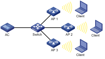
Configuration procedure
# Establish a CAPWAP tunnel between the AC and each AP. For more information, see "Managing APs." (Details not shown.)
# Enable auto-DFS for AP ap1 and set the auto-DFS mode to periodic.
<AC> system-view
[AC] wlan ap ap1 model WA536-WW
[AC-wlan-ap-ap1] radio 1
[AC-wlan-ap-ap1-radio-1] rrm
[AC-wlan-ap-ap1-radio-1-rrm] calibrate-channel self-decisive enable
[AC-wlan-ap-ap1-radio-1-rrm] calibrate-channel mode periodic
# Configure DFS trigger parameters.
[AC-wlan-ap-ap1-radio-1-rrm] crc-error-threshold 20
[AC-wlan-ap-ap1-radio-1-rrm] interference-threshold 50
[AC-wlan-ap-ap1-radio-1-rrm] tolerance-level 20
[AC-wlan-ap-ap1-radio-1-rrm] quit
[AC-wlan-ap-ap1-radio-1] quit
[AC-wlan-ap-ap1] quit
# Create RRM holddown group 10.
[AC] wlan rrm-calibration-group 10
# Add radio 1 of AP ap1 to RRM holddown group 10.
[AC-wlan-rc-group-10] ap name ap1 radio 1
# Set the channel holddown time to 600 minutes.
[AC-wlan-rc-group-10] channel holddown-time 600
# Configure auto-DFS for AP 2 and AP 3 in the same way auto-DFS is configured for AP 1. (Details not shown.)
Verifying the configuration
# Execute the display wlan rrm-status ap all command. Verify that the working channels for radios of the APs change when a channel adjustment trigger condition is met and the calibration interval is reached. (Details not shown.)
Use the display wlan rrm-history ap all command to view the channel adjustment reason. (Details not shown.)
# Verify that the channel for radio 1 on AP 1 remains unchanged within 600 minutes after the first DFS. (Details not shown.)
Scheduled auto-DFS configuration example
Network requirements
As shown in Figure 127, configure scheduled auto-DFS to adjust channels for radios of the APs when a channel adjustment trigger condition is met.
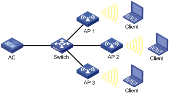
Configuration procedure
# Establish a CAPWAP tunnel between the AC and each AP. For more information, see "Managing APs." (Details not shown.)
# Create a time range.
<AC> system-view
[AC] time-range time1 from 15:20 2016/04/17 to 18:20 2016/04/17
# Create a job and assign commands to the job.
[AC] scheduler job calibratechannel
[AC-job-calibratechannel] command 1 system-view
[AC-job-calibratechannel] command 2 wlan ap ap1
[AC-job-calibratechannel] command 3 radio 1
[AC-job-calibratechannel] command 4 rrm
[AC-job-calibratechannel] command 5 calibrate-channel pronto
[AC-job-calibratechannel] quit
# Create a schedule and assign the job to the schedule.
[AC] scheduler schedule schedule1
[AC-schedule-schedule1] job calibratechannel
# Specify an execution date and time for the schedule.
[AC-schedule-schedule1] time at 20:20 2016/04/17
[AC-schedule-schedule1] quit
# Enable auto-DFS for AP ap1 and set the auto-DFS mode to scheduled.
[AC] wlan ap ap1
[AC-wlan-ap-ap1] radio 1
[AC-wlan-ap-ap1-radio-1] rrm
[AC-wlan-ap-ap1-radio-1-rrm] calibrate-channel self-decisive enable
[AC-wlan-ap-ap1-radio-1-rrm] calibrate-channel mode scheduled
# Configure AP ap1 to perform channel monitoring during time range time1.
[AC-wlan-ap-ap1-radio-1-rrm] calibrate-channel monitoring time-range time1
# Configure auto-DFS attributes.
[AC-wlan-ap-ap1-radio-1-rrm] crc-error-threshold 10
[AC-wlan-ap-ap1-radio-1-rrm] interference-threshold 40
[AC-wlan-ap-ap1-radio-1-rrm] tolerance-level 15
[AC-wlan-ap-ap1-radio-1-rrm] quit
# Configure auto-DFS for AP 2 and AP 3 in the same way auto-DFS is configured for AP 1. (Details not shown.)
Verifying the configuration
# Execute the display wlan rrm-status ap all command. Verify that the working channels for radios of the APs change when a channel adjustment trigger condition is met and the calibration interval is reached. (Details not shown.)
# Use the display wlan rrm-history ap all command to view the channel adjustment reason. (Details not shown.)
Periodic auto-TPC configuration example
Network requirements
As shown in Figure 128, configure periodic auto-TPC and set the adjacency factor to 3 to enable the AC to perform periodic auto-TPC when AP 4 joins. Add radio 1 of AP 1 to an RRM holddown group to avoid frequent power adjustments.
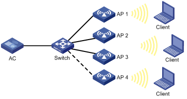
Configuration procedure
# Establish a CAPWAP tunnel between the AC and each AP. For more information, see "Managing APs." (Details not shown.)
# Enable periodic auto-TPC for AP ap1.
<AC> system-view
[AC] wlan ap ap1 model WA536-WW
[AC-wlan-ap-ap1] radio 1
[AC-wlan-ap-ap1-radio-1] rrm
[AC-wlan-ap-ap1-radio-1-rrm] calibrate-power self-decisive enable
# Configure TPC trigger parameters.
[AC-wlan-ap-ap1-radio-1-rrm] adjacency-factor 3
[AC-wlan-ap-ap1-radio-1-rrm] calibrate-power threshold 80
[AC-wlan-ap-ap1-radio-1-rrm] calibrate-power min 1
[AC-wlan-ap-ap1-radio-1-rrm] quit
[AC-wlan-ap-ap1-radio-1] quit
[AC-wlan-ap-ap1] quit
# Create RRM holddown group 10.
[AC] wlan rrm-calibration-group 10
# Add radio 1 of AP ap1 to RRM holddown group 10.
[AC-wlan-rc-group-10] ap name ap1 radio 1
# Set the power holddown time to 100 minutes.
[AC-wlan-rc-group-10] power holddown-time 100
# Configure periodic auto-TPC for AP 2, AP 3, and AP 4 in the same way periodic auto-TPC is configured for AP 1. (Details not shown.)
Verifying the configuration
# Assume that the radio of AP 4 is the power-detecting radio and this step use the name of an AP to refer to its radio. Use the display wlan rrm-status ap all command to verify the following information:
· AP 1 increases its transmit power when AP 4 detects that the power of AP 1 is lower than the power adjustment threshold.
· AP 1 decreases its transmit power when AP 4 detects that the power of AP 1 is higher than the power adjustment threshold.
· The adjusted power of AP 1 is not lower than the minimum transmit power (1 dBm in this example).
# Verify that the power of radio 1 on AP 1 remains unchanged within 100 minutes after the first TPC.
Spectrum management configuration example
Network requirements
As shown in Figure 129, configure spectrum management to restrict the transmit power of the client and allow the client to continue sending frames during channel switch.

Configuration procedure
# Enable spectrum management.
<AC> system-view
[AC] wlan ap officeap model WA536-WW
[AC-wlan-ap-officeap] radio 1
[AC-wlan-ap-officeap-radio-1] spectrum-management enable
# Set the channel capability match mode to all.
[AC-wlan-ap-officeap-radio-1] channel-capability mode all
# Set the transmit power capability match mode to all.
[AC-wlan-ap-officeap-radio-1] power-capability mode all
# Set the power constraint mode to manual and set the power constraint value to 5 dBm.
[AC-wlan-ap-officeap-radio-1] power-constraint mode manual 5
# Set the channel switch mode to continuous.
[AC-wlan-ap-officeap-radio-1] channel-switch mode continuous
Verifying the configuration
# Execute the display wlan client command to verify that the client can successfully associate with the radio. (Details not shown.)
Configuring IoT APs
An Internet of Things (IoT) AP is an AP that can communicate with IoT modules installed on the AP or connected to the AP through network cables.
An IoT AP manages IoT modules and communicates with an IoT server on behalf of the modules. The modules connect things to the Internet for intelligent identification, locating, tracking, monitoring, and management of the things.
You can apply IoT APs in different fields of the IoT by connecting them to the following IoT modules:
· RFID modules—Medical. For example, the IoT APs can provide the following medical services through identifying RFID devices:
? Infant protection through identifying mother and infant tags.
? Patients' body temperature monitoring through identifying temperature tags.
· BLE modules—Managing iBeacon devices or acting as iBeacon devices. The iBeacon technology is an Apple-developed BLE technology. This technology enables an iBeacon device to broadcast a unique identifier to nearby application software. After receiving the identifier, the application software takes actions according to the identifier to fulfill software functions.
Feature and hardware compatibility
This feature is restricted to Hong Kong and Macao.
Support for IoT capability depends on the AP model.
Configuration task list
|
Tasks at a glance |
|
(Required.) Specifying a serial number for a module |
|
(Required.) Enabling a module |
|
(Required.) Specifying the supported module type |
|
(Optional.) Setting the transmit power level for a module |
|
(Optional.) Upgrading the firmware of a module |
|
(Optional.) Restoring the factory settings for a module |
|
(Optional.) Restarting a module |
|
(Optional.) Configuring iBeacon transmission for a BLE module |
Specifying a serial number for a module
You must specify a serial number for a module when the module connects to an IoT AP through network cables. The module can come online on the AP only when the specified serial number is the same as the actual serial number of the module. A module installed on an IoT AP can come online directly no matter whether the configured serial number is the same as the module's serial number or not.
Configuration restrictions and guidelines
Deleting the serial number or specifying a different serial number than the actual serial number of an online module logs off the module if the module connects to an IoT AP through network cables.
Configuration procedure
|
Step |
Command |
Remarks |
|
1. Enter system view. |
system-view |
N/A |
|
2. Enter AP view. |
wlan ap ap-name [ model model-name ] |
The AP must be an IoT AP. |
|
3. Enter module view. |
module module-id |
N/A |
|
4. Specify a serial number for the module. |
serial-number serial-number |
By default, no serial number is specified for a module. |
Enabling a module
Enabling a module for an AP
|
Step |
Command |
Remarks |
|
1. Enter system view. |
system-view |
N/A |
|
2. Enter AP view. |
wlan ap ap-name [ model model-name ] |
The AP must be an IoT AP. |
|
3. Enter module view. |
module module-id |
N/A |
|
4. Enable the module. |
module enable |
By default, an AP uses the configuration in AP group's module view. |
Enabling a module for an AP group
|
Step |
Command |
Remarks |
|
1. Enter system view. |
system-view |
N/A |
|
2. Enter AP group view. |
wlan ap-group group-name |
N/A |
|
3. Enter AP model view. |
ap-model ap-model |
The AP model must represent an IoT AP. |
|
4. Enter module view. |
module module-id |
N/A |
|
5. Enable the module. |
module enable |
By default, a module is disabled. |
Specifying the supported module type
For a module to operate correctly, make sure the specified module type is the same as the actual module type of the module.
The following module types are available:
· BLE—H3C-developed modules that support the Bluetooth protocol.
· IoT—IoT modules that are developed by third-party vendors.
Specifying the supported module type for an AP
|
Step |
Command |
Remarks |
|
1. Enter system view. |
system-view |
N/A |
|
2. Enter AP view. |
wlan ap ap-name [ model model-name ] |
The AP must be an IoT AP. |
|
3. Enter module view. |
module module-id |
N/A |
|
4. Specify the supported module type. |
type { ble | iot } |
By default, an AP uses the configuration in AP group's module view. |
Specifying the supported module type for an AP group
|
Step |
Command |
Remarks |
|
1. Enter system view. |
system-view |
N/A |
|
2. Enter AP group view. |
wlan ap-group group-name |
N/A |
|
3. Enter AP model view. |
ap-model ap-model |
The AP model must represent an IoT AP. |
|
4. Enter module view. |
module module-id |
N/A |
|
5. Specify the supported module type. |
type { ble | iot } |
By default, no supported module type is specified. |
Setting the transmit power level for a module
A module has the following levels of transmit power:
· Level 1 (4 dBm).
· Level 2 (–1 dBm).
· Level 3 (–5 dBm).
· Level 4 (–9 dBm).
Setting the transmit power level for a module in module view
|
Step |
Command |
Remarks |
|
1. Enter system view. |
system-view |
N/A |
|
2. Enter AP view. |
wlan ap ap-name [ model model-name ] |
N/A |
|
3. Enter module view. |
module module-id |
N/A |
|
4. Set the transmit power level for the module. |
tx-power power |
By default, a module uses the configuration in AP group's module view. |
Setting the transmit power level for a module in AP group's module view
|
Step |
Command |
Remarks |
|
1. Enter system view. |
system-view |
N/A |
|
2. Enter AP group view. |
wlan ap-group group-name |
N/A |
|
3. Enter AP model view. |
ap-model ap-model |
N/A |
|
4. Enter module view. |
module module-id |
N/A |
|
5. Set the transmit power level for the module. |
tx-power power |
By default, the transmit power level is 1, which indicates a transmit power of 4 dBm. |
Upgrading the firmware of a module
You can use either of the following methods to upgrade the firmware of a module:
· Manual upgrade—Use the specified image file to manually upgrade the module's firmware.
· Automatic upgrade—Configure the automatic firmware upgrade feature to enable the module to immediately upgrade its firmware if its firmware version is different from the version stored in the AP's image file. After you enable this feature for a module, this feature takes effect every time the connected IoT AP restarts.
If you want the module's firmware version to be consistent with the version stored in the AP's image file, use automatic upgrade. In other cases, use manual upgrade.
Configuring automatic module firmware upgrade
Configuring automatic module firmware upgrade in module view
|
Step |
Command |
Remarks |
|
1. Enter system view. |
system-view |
N/A |
|
2. Enter AP view. |
wlan ap ap-name [ model model-name ] |
N/A |
|
3. Enter module view. |
module module-id |
N/A |
|
4. Configure automatic module firmware upgrade. |
module firmware-upgrade { disable | enable } |
By default, a module uses the configuration in AP group's module view. |
Configuring automatic module firmware upgrade in AP group's module view
|
Step |
Command |
Remarks |
|
1. Enter system view. |
system-view |
N/A |
|
2. Enter AP group view. |
wlan ap-group group-name |
N/A |
|
3. Enter AP model view. |
ap-model ap-model |
N/A |
|
4. Enter module view. |
module module-id |
N/A |
|
5. Configure automatic module firmware upgrade. |
rfid-tracking ble advertisement { disable | enable } |
By default, automatic module firmware upgrade is disabled for a BLE module. |
Manually upgrading the firmware of a module
When you perform a manual firmware upgrade for a module, follow these restrictions and guidelines:
· Save the module's image file to the AC's local folder.
· Make sure the automatic firmware upgrade feature is disabled for the module. Automatic firmware upgrade performs version consistency check every time the connected IoT AP restarts and upgrades the module's firmware to the version stored in the AP's image file as necessary.
To manually upgrade the firmware of a module:
|
Step |
Command |
|
1. Enter system view. |
system-view |
|
2. Manually upgrade the firmware of a module. |
wlan execute module firmware-upgrade { ap ap-name | ap-group group-name ap-model ap-model } module module-id firmware-path filepath |
Restoring the factory settings for a module
|
Step |
Command |
|
1. Enter system view. |
system-view |
|
2. Restore the factory settings for a module. |
wlan execute module restore-factory ap ap-name module module-id |
Restarting a module
|
Step |
Command |
|
1. Enter system view. |
system-view |
|
2. Restart a module. |
wlan execute module reset ap ap-name module module-id |
Configuring iBeacon transmission for a BLE module
This feature enables a BLE module to periodically broadcast iBeacon advertisements. An iBeacon advertisement contains a UUID, a Major ID, a Minor ID, and measured power. Application software that receives the iBeacon advertisement will take specific actions according to the advertisement information to fulfill software functions.
Configuring iBeacon transmission for a BLE module in module view
|
Step |
Command |
Remarks |
|
1. Enter system view. |
system-view |
N/A |
|
2. Enter AP view. |
wlan ap ap-name [ model model-name ] |
N/A |
|
3. Enter module view. |
module module-id |
N/A |
|
4. Configure iBeacon transmission for a BLE module. |
rfid-tracking ble advertisement { disable | enable } |
By default, a module uses the configuration in AP group's module view. |
|
5. Configure the advertisement information. |
rfid-tracking ble advertisement { major-id major-id | measured-power | minor-id minor-id | uuid uuid } |
By default, a module uses the configuration in AP group's module view. |
|
6. Set the interval for the BLE module to broadcast iBeacon advertisements. |
rfid-tracking ble advertisement interval interval |
By default, a module uses the configuration in AP group's module view. |
Configuring iBeacon transmission for a BLE module in AP group's module view
|
Step |
Command |
Remarks |
|
1. Enter system view. |
system-view |
N/A |
|
2. Enter AP group view. |
wlan ap-group group-name |
N/A |
|
3. Enter AP model view. |
ap-model ap-model |
N/A |
|
4. Enter module view. |
module module-id |
N/A |
|
5. Configure iBeacon transmission for a BLE module. |
rfid-tracking ble advertisement { disable | enable } |
By default, iBeacon transmission is disabled for a BLE module. |
|
6. Configure the advertisement information. |
rfid-tracking ble advertisement { major-id major-id | measured-power | minor-id minor-id | uuid uuid } |
By default, the UUID is 0, Major ID is 1, Minor ID is 1, and measured power is -58 dBm in an iBeacon advertisement. |
|
7. Set the interval for the BLE module to broadcast iBeacon advertisements. |
rfid-tracking ble advertisement interval interval |
By default, a BLE module broadcasts iBeacon advertisements every 100 centiseconds (1 second). |
Displaying and maintaining IoT APs
Execute display commands in any view.
|
Task |
Command |
|
Display firmware upgrade information for modules. |
display wlan module firmware-upgrade history { all | ap ap-name module module-id } |
|
Display module information for an AP. |
display wlan module-information ap ap-name module module-id |
Configuring CM tunnels
This feature is restricted to Hong Kong and Macao.
Overview
A cloud management tunnel (CM tunnel) is a management tunnel established between a local device and the H3C Oasis server. It enables you to manage the local device from the H3C Oasis server without accessing the network where the device resides.
CM tunnel establishment
This section uses an AC and the H3C Oasis server as an example. The CM tunnel is established as follows:
1. The AC sends a registration request to the H3C Oasis server.
2. The H3C Oasis server sends a registration success packet to the AC.
The H3C Oasis server sends a registration success packet to the AC only if the serial number of the AC has been added to the H3C Oasis server.
|
|
NOTE: If the serial number of the AC has not been added to the H3C Oasis server, the H3C Oasis server sends a registration failure packet to the AC. After receiving the registration failure packet, the AC starts the re-establishment timer and requests to re-establish the CM tunnel when the timer expires. |
3. The AC sends a CM tunnel request to the H3C Oasis server.
4. The H3C Oasis server sends a CM tunnel response to the AC.
5. The AC uses the CM tunnel interface to establish a CM tunnel with the H3C Oasis server.
Figure 130 CM tunnel establishment
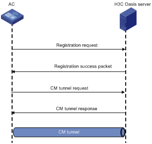
Configuring a CM tunnel
For a successful CM tunnel establishment, add the serial number of the device to be managed to the H3C Oasis server.
To configure a CM tunnel:
|
Step |
Command |
Remarks |
|
1. Enter system view. |
system-view |
N/A |
|
2. Configure the domain name of the H3C Oasis server. |
cmtunnel server domain domain-name |
By default, the domain name of the H3C Oasis server is not configured. |
Displaying and maintaining CM tunnels
Execute display commands in any view.
|
Task |
Command |
|
Display CM tunnel state information. |
display cmtunnel state |
CM tunnel configuration example
Network requirements
As shown in Figure 131, configure the AC to establish a CM tunnel with the H3C Oasis server.
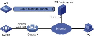
Configuration procedure
1. Configure IP addresses for interfaces as shown in Figure 131, and configure a routing protocol to make sure the devices can reach each other. (Details not shown.)
2. Log in to the H3C Oasis server to add the serial number of the AC to the server. (Details not shown.)
3. Configure the domain name of the H3C Oasis server as lvzhou.h3c.com.
<AC> system-view
[AC] cmtunnel server domain-name lvzhou.h3c.com
|
|
NOTE: The DNS service is provided by the ISP DNS server. |
Verifying the configuration
# Verify that the AC and the H3C Oasis server have established a CM tunnel.
[AC] display cmtunnel state
Server address : 10.1.1.1
Server name : lvzhou.h3c.com
Local port : 80
Connection state : Established
Device state : Request_success
Configuring cloud connections
This feature is restricted to Hong Kong and Macao.
Overview
A cloud connection is a management tunnel established between a local device and the H3C Oasis server. It enables you to manage the local device from the H3C Oasis server without accessing the network where the device resides.
The service modules on the local device can establish multiple subconnections with the microservices on the H3C Oasis server. These subconnections are independent from each other and provide separate communication channels for different services. This mechanism avoids interference among different services.
Cloud connection establishment
This section uses an AC and the H3C Oasis server as an example. The cloud connection is established as follows:
1. The AC sends an authentication request to the H3C Oasis server.
2. The H3C Oasis server sends an authentication success packet to the AC.
The AC passes the authentication only if the serial number of the AC has been added to the H3C Oasis server. If the authentication fails, the H3C Oasis server sends an authentication failure packet to the AC.
3. The AC sends a registration request to the H3C Oasis server.
4. The H3C Oasis server sends a registration response to the AC.
The registration response contains the uniform resource locator (URL) used to establish a cloud connection.
5. The AC uses the URL to send a handshake request (changing the protocol from HTTP to WebSocket) to the H3C Oasis server.
6. The H3C Oasis server sends a handshake response to the AC to finish establishing the cloud connection.
|
|
NOTE: After the cloud connection is established, the AC automatically obtains the subconnection URLs and establishes subconnections with the H3C Oasis server based on the service needs. |
Figure 132 Establishing a cloud connection
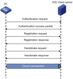
Configuring a cloud connection
For a successful cloud connection establishment, add the serial number of the device to be managed to the H3C Oasis server.
To configure a cloud connection:
|
Step |
Command |
Remarks |
|
1. Enter system view. |
system-view |
N/A |
|
2. Configure the domain name of the H3C Oasis server. |
cloud-management server domain domain-name |
By default, the domain name of the H3C Oasis server is not configured. |
|
3. Set the keepalive interval. |
cloud-management keepalive interval |
By default, the keepalive interval is 180 seconds. If the local device does not receive a response from the H3C Oasis server within three keepalive intervals, the device sends a registration request to re-establish the cloud connection. |
|
4. Specify the TCP port number used to establish cloud connections. |
cloud-management server port port-number |
By default, the TCP port number used to establish cloud connections is 443. |
Displaying and maintaining cloud connections
Execute display commands in any view.
|
Task |
Command |
|
Display cloud connection state information. |
display cloud-management state |
Cloud connection configuration example
Network requirements
As shown in Figure 133, configure the AC to establish a cloud connection with the H3C Oasis server.
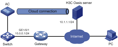
Configuration procedure
1. Configure IP addresses for interfaces as shown in Figure 133, and configure a routing protocol to make sure the devices can reach each other. (Details not shown.)
2. Log in to the H3C Oasis server to add the serial number of the AC to the server. (Details not shown.)
3. Configure the domain name of the H3C Oasis server as lvzhouv3.h3c.com.
<AC> system-view
[AC] cloud-management server domain lvzhouv3.h3c.com
|
|
NOTE: The DNS service is provided by the ISP DNS server. |
Verifying the configuration
# Verify that the AC and the H3C Oasis server have established a cloud connection.
[AC] display cloud-management state
Cloud connection state : Established
Device state : Request_success
Cloud server address : 10.1.1.1
Cloud server domain name : lvzhouv3.h3c.com
Local port : 443
Connected at : Wed Jan 27 14:18:40 2016
Duration : 00d 00h 02m 01s
Process state : DNS not parsed
Failure reason : DNS parse failed
Last down reason : socket connection error (Details:N/A)
Last down at : Wed Jan 27 13:18:40 2016
Last report failure reason : SSL sending failure (Details:ssl msg = ssl error read ,system msg = No such file or directory)
Last report failure at : Wed Jan 27 13:18:40 2016
Dropped packets after reaching buffer limit : 0
Total dropped packets : 1
Last report incomplete reason : N/A
Last report incomplete at : N/A
Buffer full count : 0
Configuring WLAN IP snooping
Overview
WLAN IP snooping enables an AP to learn clients' IP addresses through snooping ARP, DHCP, and HTTP packets and generate snooping entries that record IP addresses, MAC addresses, and learning method. The entries will be used by IP Source Guard to determine whether to forward client packets. For more information about IP Source Guard, see Security Configuration Guide.
Client IPv4 address learning
An AP learns client IPv4 addresses by using the following methods:
· Snooping DHCPv4 packets exchanged between client and server.
For more information about DHCP, see Layer 3—IP Services Configuration Guides.
· Snooping ARP packets sent by clients.
For more information about ARP, see Layer 3—IP Services Configuration Guides.
· Snooping HTTP requests redirected to the portal server.
For more information about portal authentication, see Security Configuration Guides.
The priorities for learning IP addresses through snooping DHCPv4 packets, ARP packets, and HTTP requests are in descending order.
Client IPv6 address learning
An AP learns client IPv6 addresses by using the following methods:
· Snooping DHCPv6 packets exchanged between client and server.
For more information about DHCPv6, see Layer 3—IP Services Configuration Guides.
· Snooping ND packets, including Router Advertisement (RA) packets, Neighbor Solicitation (NS) packets, and Neighbor Advertisement (NA) packets sent by clients.
For more information about ND, see Layer 3—IP Services Configuration Guides.
· Snooping HTTP requests redirected to the portal server.
For more information about portal authentication, see Security Configuration Guides.
The priorities for learning IPv6 addresses through snooping DHCPv6 packets, ND packets, and HTTP requests are in descending order.
WLAN IP snooping configuration task list
|
Tasks at a glance |
|
(Optional.) Disabling snooping ARP packets |
|
(Optional.) Disabling snooping ND packets |
|
(Optional.) Disabling SNMP from getting client IPv6 addresses learned from ND packets |
|
(Optional.) Enabling snooping HTTP requests redirected to the portal server |
Disabling snooping ARP packets
About ARP packet snooping
By default, an AP learns client IPv4 addresses by snooping ARP and DHCPv4 packets. Perform this task to disable client IPv4 address learning from ARP packets.
Procedure
|
Step |
Command |
Remarks |
|
1. Enter system view. |
system-view |
N/A |
|
2. Create a service template and enter its view. |
wlan service-template service-template-name |
N/A |
|
3. Disable snooping ARP packets. |
undo client ipv4-snooping arp-learning enable |
By default, snooping ARP packets is enabled. |
Disabling snooping ND packets
|
Step |
Command |
Remarks |
|
1. Enter system view. |
system-view |
N/A |
|
2. Create a service template and enter its view. |
wlan service-template service-template-name |
N/A |
|
3. Disable snooping ND packets. |
undo client ipv6-snooping nd-learning enable |
By default, snooping ND packets is enabled. |
Disabling SNMP from getting client IPv6 addresses learned from ND packets
This feature enables SNMP to obtain only client IPv6 addresses learned from DHCPv6 packets.
To disable SNMP from getting client IPv6 addresses learned from ND packets:
|
Step |
Command |
Remarks |
|
1. Enter system view. |
system-view |
N/A |
|
2. Create a service template and enter its view. |
wlan service-template service-template-name |
N/A |
|
3. Disable SNMP from getting client IPv6 addresses learned from ND packets. |
undo client ipv6-snooping snmp-nd-report enable |
By default, SNMP obtains client IPv6 addresses learned from both DHCPv6 and ND packets. |
Enabling snooping HTTP requests redirected to the portal server
The AC can use this method to learn IP addresses of portal-authenticated clients.
To enable snooping HTTP requests redirected to the portal server:
|
Step |
Command |
Remarks |
|
1. Enter system view. |
system-view |
N/A |
|
2. Create a service template and enter its view. |
wlan service-template service-template-name |
N/A |
|
3. Enable snooping HTTP requests redirected to the portal server. |
client ip-snooping http-learning enable |
By default, snooping HTTP requests is disabled. |
WLAN IP snooping configuration example
Network requirements
As shown in Figure 134, configure the AP to learn the client's IPv6 address only from DHCPv6 packets.
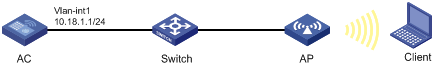
Configuration procedure
# Configure wireless services. (Details not shown.)
For more information, see "Managing APs" and "Configuring WLAN access."
# Disable snooping ND packets.
<AC> system-view
[AC] wlan service-template service
[AC-wlan-st-service] undo client ipv6-snooping nd-learning enable
Configuring WLAN fast forwarding
Overview
WLAN fast forwarding enhances forwarding performance. When fast forwarding is enabled, the AC performs concurrent forwarding by using the multi-core CPU and the 5-tuple table. The AC learns the source IP, source port, destination IP, destination port, and protocol during forwarding and uses high-speed buffer technology to save the information in the 5-tuple table.
Feature and hardware compatibility
|
Hardware series |
Model |
Fast forwarding compatibility |
|
WX1800H series |
WX1804H WX1810H WX1820H WX1840H |
No |
|
WX3800H series |
WX3820H WX3840H |
Yes |
|
WX5800H series |
WX5860H |
Yes |
Configuring WLAN fast forwarding
|
Step |
Command |
Remarks |
|
1. Enter system view. |
system-view |
N/A |
|
2. Enable WLAN fast forwarding. |
wlan fast-forwarding enable |
By default, WLAN fast forwarding is enabled. |
Displaying and maintaining WLAN fast forwarding
Execute display commands in any view.
|
Task |
Command |
|
Display WLAN fast forwarding status. |
display wlan fast-forwarding status |
Configuring WLAN probe
Overview
WLAN probe enables APs to monitor the WLAN and collect information about wireless devices in the WLAN. Then, the APs send the collected information to the specified server for further analysis.
WLAN probe system
As shown in Figure 135, a WLAN probe system contains the following devices:
· Sensors—APs enabled with WLAN probe. They scan the channels, collect wireless device information, and report the information to the server.
· AC—Manages sensors and reports information received from sensors to the server.
· Server—Analyzes the information received from sensors and the AC.
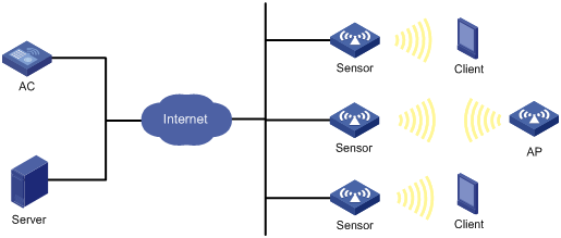
Work mechanism
A WLAN probe system operates as follows:
1. Wireless devices send 802.11 packets.
2. Sensors collect wireless device information, such as MAC address, device type, RSSI, and time stamp from the packets.
3. Sensors send collected device information to the AC or server.
4. The server analyzes the received information.
WLAN probe configuration task list
|
Tasks at a glance |
|
(Required.) Enabling WLAN probe |
|
(Required.) Specifying a server to receive wireless device information |
|
(Optional.) Configuring sensors to report wireless device information to the AC |
|
(Optional.) Enabling real-time reporting of wireless device information to the UDP server |
|
(Optional.) Setting the coordinates for a sensor |
|
(Optional.) Configuring wireless device filtering |
|
(Optional.) Setting device entry timers |
Enabling WLAN probe
To enable WLAN probe in radio view:
|
Step |
Command |
Remarks |
|
1. Enter system view. |
system-view |
N/A |
|
2. Enter AP view. |
wlan ap ap-name |
N/A |
|
3. Enter radio view. |
radio radio-id |
N/A |
|
4. Enable WLAN probe. |
client-proximity-sensor enable |
By default, a radio uses the configuration in AP group radio view. |
To enable WLAN probe in AP group radio view:
|
Step |
Command |
Remarks |
|
1. Enter system view. |
system-view |
N/A |
|
2. Enter AP group view. |
wlan ap-group group-name |
N/A |
|
3. Enter AP model view. |
ap-model ap-model |
N/A |
|
4. Enter radio view. |
radio radio-id |
N/A |
|
5. Enable WLAN probe. |
client-proximity-sensor enable |
By default, WLAN probe is disabled. |
Specifying a server to receive wireless device information
About specifying a server to receive wireless device information
Perform this task to specify a server for a sensor or the AC to report wireless device information.
Restrictions and guidelines
For the AC to report device information to the server, you must enable sensors to report information about detected devices to the AC.
Procedure
To specify an HTTPS server:
|
Step |
Command |
Remarks |
|
1. Enter system view |
system-view |
N/A |
|
2. Specify an HTTPS server to receive wireless device information. |
client-proximity-sensor server string [ window-time window-time-value | partner partner-value ] * |
By default, no HTTPS server is specified. |
To specify a UDP server for the AC:
|
Step |
Command |
Remarks |
|
1. Enter system view |
system-view |
N/A |
|
2. Specify a UDP server to receive wireless device information. |
client-proximity-sensor udp-server ip-address port port-number [ interval interval | preshared-key [ cipher | simple ] key-string ] * |
By default, no UDP server is specified. |
To specify a UDP server for a sensor:
|
Step |
Command |
Remarks |
|
1. Enter system view |
system-view |
N/A |
|
2. Enter AP view. |
wlan ap ap-name |
N/A |
|
3. Specify a UDP server to receive wireless device information. |
client-proximity-sensor ap-udp-server ip-address port port-number [ interval interval | preshared-key [ cipher | simple ] key-string ] * |
By default, no UDP server is specified. |
Configuring sensors to report wireless device information to the AC
|
Step |
Command |
Remarks |
|
1. Enter system view. |
system-view |
N/A |
|
2. Enable sensors to report information about detected devices to the AC. |
client-proximity-sensor report-ac enable |
By default, sensors do not report information about detected devices to the AC. |
|
3. (Optional.) Set the interval at which sensors report information about detected devices to the AC. |
client-proximity-sensor report-ac-interval interval |
By default, sensors report information about detected devices to the AC every 3000 milliseconds. |
Enabling real-time reporting of wireless device information to the UDP server
About real-time reporting of wireless device information to the UDP server
After you enable this feature, the device information is reported to the UDP server in real time, rather than at the specified intervals.
Procedure
|
Step |
Command |
Remarks |
|
1. Enter system view. |
system-view |
N/A |
|
2. Enable real-time reporting of wireless device information to the UDP server. |
client-proximity-sensor rt-report enable |
By default, real-time reporting of wireless device information to the UDP server is disabled. |
Setting the coordinates for a sensor
|
Step |
Command |
Remarks |
|
1. Enter system view. |
system-view |
N/A |
|
2. Enter AP view. |
wlan ap ap-name |
N/A |
|
client-proximity-sensor coordinates longitude longitude-value latitude latitude-value |
Configuring wireless device filtering
About wireless device filtering
Perform this task to configure whether the information about the specified devices is reported or not.
Procedure
|
Step |
Command |
Remarks |
|
1. Enter system view |
system-view |
N/A |
|
2. Configure the MAC address filtering list. |
client-proximity-sensor filter-list list |
By default, the MAC address filtering list is not configured. |
|
3. Set the RSSI threshold for clients or APs. |
client-proximity-sensor rssi-threshold { ap ap-rssi-value | client client-rssi-value } |
By default, the RSSI thresholds for clients and APs are not set. |
|
4. Set the RSSI difference threshold for wireless device information reporting. |
client-proximity-sensor rssi-change-threshold threshold-value |
By default, the RSSI difference threshold is 100. |
|
5. Enable reporting of information about Apple terminals that use a random MAC address. |
client-proximity-sensor random-mac-report enable |
By default, information about Apple terminals that use a random MAC address is not reported. |
|
6. Enable reporting of AP information to the UDP server. |
client-proximity-sensor report-ap enable |
By default, the information about APs is not reported to the UDP server. |
Setting device entry timers
|
Step |
Command |
Remarks |
|
1. Enter system view. |
system-view |
N/A |
|
2. Set the AP entry timers. |
client-proximity-sensor ap-timer inactive inactive-value aging aging-value |
By default, the inactive time and aging time for AP entries are 300 seconds and 600 seconds, respectively. |
|
3. Set the client entry timers. |
client-proximity-sensor client-timer inactive inactive-value aging aging-value |
By default, the inactive time and aging time for client entries are 300 seconds and 600 seconds, respectively. |
Displaying and maintaining WLAN probe
Execute display commands in any view and reset commands in user view.
|
Task |
Command |
|
Display information about wireless devices detected by sensors. |
display client-proximity-sensor device [ ap | client | mac-address mac-address ] [ verbose ] |
|
Display information about sensors. |
display client-proximity-sensor sensor |
|
Display information received from sensors. |
display client-proximity-sensor statistics receive |
|
Clear wireless device information. |
reset client-proximity-sensor device { ap | client | mac-address mac-address | all } |
|
Clear information received from sensors. |
reset client-proximity-sensor statistics |
WLAN probe configuration examples
WLAN probe configuration example
Network requirements
As shown in Figure 136, AP 1 and AP 2 provide wireless services for clients through SSID abc.
Enable WLAN probe on the sensor, and configure the AC to report the received wireless device information to the server.
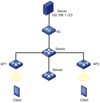
Configuration procedure
# Configure wireless service settings on the AC. (Details not shown.)
For more information, see "Configuring WLAN access."
# Create AP Sensor, and enable WLAN probe for the AP.
<AC> system-view
[AC] wlan ap Sensor model WA536-WW
[AC-wlan-ap-Sensor] serial-id 219801A1NQB117012935
[AC-wlan-ap-Sensor] radio 1
[AC-wlan-ap-Sensor-radio-1] radio enable
[AC-wlan-ap-Sensor-radio-1] client-proximity-sensor enable
[AC-wlan-ap-Sensor-radio-1] quit
[AC-wlan-ap-Sensor] radio 2
[AC-wlan-ap-Sensor-radio-2] radio enable
[AC-wlan-ap-Sensor-radio-2] client-proximity-sensor enable
[AC-wlan-ap-Sensor-radio-1] quit
[AC-wlan-ap-Sensor] quit
# Configure the sensor to report wireless device information to the AC.
[AC] client-proximity-sensor report-ac enable
# Configure the AC to report wireless device information to the UDP server with IP address 192.168.1.123 and port number 1234, and set the report interval to 20 seconds.
[AC] client-proximity-sensor udp-server 192.168.1.123 port 1234 interval 20
Verifying the configuration
# Display wireless device information detected by the sensor.
[AC] display client-proximity-sensor device
Total 3 detected devices
MAC address Type Duration Sensors Channel Status
0021-632F-E9E5 Client 00h 10m 46s 1 11 Active
0021-6330-148B Client 00h 10m 46s 1 6 Active
0212-34B8-A8E0 Client 00h 10m 46s 1 1 Active
# On the management console of the server, view the wireless device information received from the AC. (Details not shown.)
Configuring WLAN process maintenance
Overview
WLAN process maintenance enables the system to monitor and collect the CPU usage, memory usage, and thread status of WLAN processes for administrators to troubleshoot the WLAN. It provides the following features:
· Memory usage monitoring—Records the memory usage of each monitored process every five minutes and performs a calculation every 2 hours. The system determines that memory leakage occurs and outputs a log entry when the memory usage of a process exceeds the threshold and shows an upward trend in the past seven days.
· CPU usage monitoring—Periodically records the CPU usage of each monitored process and performs a calculation. If the calculated usage exceeds 5%, the system outputs a log entry.
· Thread state monitoring—Sends a message to the thread of each monitored process every 30 seconds. If the system fails to receive any response within a specific period, it determines that the thread is in defunct state and outputs a log entry.
Enabling WLAN process maintenance
|
Step |
Command |
Remarks |
|
1. Enter system view. |
system-view |
N/A |
|
2. Enable WLAN process maintenance. |
maintain enable |
By default, WLAN process maintenance is enabled. |
Setting the inactive timeout
About the inactive timeout
When WLAN process maintenance is enabled, the system periodically sends a message to each monitored process to examine the process state. If the system fails to receive any response from a process when the inactive timeout expires, the system determines that the process is in defunct state.
Restrictions and guidelines
The configuration starts to take effect the first time the system sends a message upon execution of the command.
You can set the inactive timeout only for the apmgr, stamgr, and portal processes.
The feature takes effect only when WLAN process maintenance is enabled.
Procedure
|
Step |
Command |
Remarks |
|
1. Enter system view. |
system-view |
N/A |
|
2. Set the inactive timeout for a process. |
maintain process process-name inactive-time value |
By default, the inactive timeout is 10 minutes. |
Setting the memory usage threshold
About the memory usage threshold
The system outputs a log entry when the memory usage of the specified process exceeds the threshold.
Restrictions and guidelines
This feature takes effect only when WLAN process maintenance is enabled.
You can set the threshold only for the apmgr, stamgr, and portal processes.
Procedure
|
Step |
Command |
Remarks |
|
1. Enter system view. |
system-view |
N/A |
|
2. Set the memory usage threshold. |
maintain process process-name memory-threshold value |
By default, the memory usage threshold is 300 MB. |
Displaying and maintaining WLAN process maintenance
Execute display commands in any view.
|
Task |
Command |
|
Display the CPU usage history of WLAN processes. |
display maintain cpu-usage history process process-name [ days-ago days ] [ start-time value ] [ interval interval ] |
|
Display memory usage history of WLAN processes. |
display maintain memory-usage history process process-name [ days-ago days ] [ start-time value ] [ interval interval ] |
Numerics
3GPP
Hotspot 2.0 3GPP information configuration, 350
802.11, 49, See also under 802
802.11a radio mode, 49
802.11a radio transmission rate, 50
802.11ac bandwidth mode set, 88
802.11ac configuration, 86
802.11ac NSS set, 86
802.11ac radio mode, 49
802.11ac radio transmission rate, 50
802.11b radio mode, 49
802.11b radio transmission rate, 50
802.11g protection configuration, 74
802.11g radio mode, 49
802.11g radio transmission rate, 50
802.11n A-MPDU aggregation method, 78
802.11n A-MSDU aggregation method, 78
802.11n bandwidth mode set, 83
802.11n configuration, 77, 96
802.11n energy saving configuration, 85
802.11n LDPC configuration, 79
802.11n MCS index set, 81
802.11n MIMO mode, 84
802.11n protection configuration, 85
802.11n radio mode, 49
802.11n radio transmission rate, 50
802.11n short GI configuration, 79
802.11n STBC configuration, 80
802.11r configuration, 313
AP group configuration, 46
AP management, 1, 4, 25
auto AP configuration, 41
CAPWAP tunnel establishment (DHCP), 25
CAPWAP tunnel establishment (DHCPv6), 31
CAPWAP tunnel establishment (DNS), 36
inter-AC roaming, 255
intra-AC roaming, 252
over-the-air FT and 802.1X authentication, 324
over-the-air FT and PSK authentication, 317
over-the-DS FT and 802.1X authentication, 320
over-the-DS FT and PSK authentication, 313
radio AP collision avoidance mode, 73
radio basic configuration, 92
radio management configuration, 49, 59, 92
radio MCS, 51
radio mode specify, 62
radio modes, 49
radio RTS threshold set, 74
radio transmission rate, 50
radio VHT-MCS, 54
SVP mapping, 241
traffic differentiation, 242
WIPS configuration, 194, 218
wireless location configuration, 328, 328, 343
WLAN 802.11r configuration, 310
WLAN access configuration, 100, 105, 124
WLAN dual-link backup mode configuration, 296
WLAN Hotspot 2.0 configuration, 377
WLAN QoS CAC configuration, 240
WLAN QoS configuration, 229, 239
WLAN QoS WMM configuration, 239
WLAN radio resource measurement, 277
WLAN resource measurement, 281
WLAN roaming, 252
WLAN RRM holddown group, 389, 393
WLAN RRM on-demand TPC, 393
WLAN RRM periodic auto-TPC, 392
WLAN RRM TPC configuration, 389
WLAN RRM TPC min transmit power, 391
WLAN RRM TPC mode configuration, 390
WLAN RRM TPC trigger parameters, 390
802.11ac
allowingaccess for only 802.11ac clients, 88
configuring access for only 802.11n and 802.11ac clients, 82
802.11b
configuring 802.11b client access, 71
802.11n
configuring access for only 802.11n and 802.11ac clients, 82
802.11r
operation, 310
protocols and standards, 312
802.1X
authentication initiation, 161
authentication process, 161
authentication request attempts max, 171
authentication timers, 171
EAP mode, 173
EAP relay, 161
EAP relay authentication, 161
EAP relay enable, 170
EAP relay termination, 163
EAP termination, 161
EAP termination enable, 170
WLAN authentication, 160
WLAN authentication accounting-start trigger, 179
WLAN authentication accounting-update trigger, 180
WLAN authentication authenticator, 174
WLAN authentication configuration, 169, 169, 181
WLAN authentication mode, 165, 173
WLAN online user handshake, 176
WLAN security 802.1X AKM configuration, 148
WLAN security configuration, 128, 136, 142
WLAN security private PSK+MAC authentication configuration, 157
WLAN security PSK+MAC authentication configuration, 146
WLAN security RSNA mechanism, 129
WLAN security RSNA mechanism (authentication), 129
WLAN security RSNA mechanism (key management), 129
WLAN service template authentication domain, 177
WLAN service template clients max, 177
A
AC
active AC number set, 300
AP AC connection priority, 6
AP preprovisioned settings auto assignment, 21
AP request retransmission, 13
CAPWAP AC discovery, 1
CAPWAP tunnel, 1
CAPWAP tunnel configuration, 11
CAPWAP tunnel establishment, 2
CAPWAP tunnel establishment configuration, 5
CAPWAP tunnel latency detection, 11
channel scanning blacklist or whitelist configuration, 286
default power level configuration, 15
inter-AC roaming through over-the-air FT, 311
intra-AC roaming through over-the-air FT, 310
intra-AC roaming through over-the-DS FT, 311
management frame protection, 140
PSK authentication and bypass authentication configuration, 144
radio 802.11n configuration, 77
radio disable, 61
radio enable, 61
remote AP configuration, 14
service anomaly detection, 23
shared key authentication configuration, 142
SNMP gets ND-learned client IPv6 address disable, 420
unicast discovery request response enable, 7
WLAN absolute forwarding preferred configuration, 288
WLAN access client idle timeout, 113
WLAN access permitted AP group client access, 118
WLAN access permitted SSID client access, 118
WLAN band navigation, 290, 292
WLAN bandwidth-mode load balancing configuration, 268, 273
WLAN channel scanning configuration, 284
WLAN channel scanning configuration (on an AC), 288
WLAN fast forwarding configuration, 422
WLAN high availability backup, 295
WLAN Inter-AC roaming topology, 248
WLAN Intra-AC roaming topology, 247
WLAN IP snooping ARP packets disable, 420
WLAN IP snooping configuration, 419, 421
WLAN IP snooping HTTP request redirected to portal server, 420
WLAN IP snooping ND packets disable, 420
WLAN load balancing configuration, 260
WLAN load balancing configuration (for a load balancing group), 270
WLAN load balancing configuration (for radios), 265
WLAN process maintenance, 430
WLAN relative forwarding preferred configuration, 288
WLAN RRM configuration, 381, 384, 399
WLAN RRM DFS, 381
WLAN RRM DFS configuration, 384
WLAN RRM DFS trigger parameter, 385
WLAN RRM holddown group, 389, 393
WLAN RRM on-demand DFS configuration, 389
WLAN RRM on-demand TPC, 393
WLAN RRM periodic auto-DFS configuration, 385, 399
WLAN RRM periodic auto-TPC, 392
WLAN RRM periodic auto-TPC configuration, 402
WLAN RRM scheduled auto-DFS configuration, 386, 401
WLAN RRM TPC, 382
WLAN RRM TPC configuration, 389
WLAN RRM TPC min transmit power, 391
WLAN RRM TPC mode configuration, 390
WLAN RRM TPC trigger parameters, 390
WLAN security 802.1X AKM configuration, 148
WLAN security configuration, 128, 136, 142
WLAN security private PSK+MAC authentication configuration, 157
WLAN security PSK+MAC authentication configuration, 146
WLAN session-mode load balancing configuration, 265, 270
WLAN traffic-mode load balancing configuration, 267, 272
AC role
active AC, 298
direct connected AC, 298
master AC, 298
non-active AC, 298
subordinate AC, 298
access
WLAN authentication BYOD, 168
WLAN authentication configuration, 169, 169, 181
WLAN authentication overview, 160
Access Point Information Database. See APDB
accessing
WLAN client access control, 102
WLAN client access control (AP group-based), 102
WLAN client access control (blacklist-based), 104
WLAN client access control (SSID-based), 103
WLAN client access control (whitelist-based), 104
accounting
WLAN authentication accounting-start trigger, 179
WLAN authentication accounting-update trigger, 180
ACL
WLAN authentication ACL assignment, 168
active
WLAN access scanning process, 100, 346
Adaptive Noise Immunity. Use ANI
adding
mobility group member, 250
WLAN access client to blacklist (static)(on AC), 119
WLAN access client to whitelist, 118
aggregating
radio MPDU aggregation, 50
radio MSDU aggregation, 50
aging
WLAN client cache aging time, 108
AKM
WLAN security 802.1X AKM configuration, 148
WLAN security AKM mode configuration, 137
allowing
access for only 802.11ac clients, 88
radio 802.11n A-MPDU aggregation method, 78
radio 802.11n A-MSDU aggregation method, 78
antenna
radio antenna gain set, 65
radio antenna type set, 64
AP
802.11r, 312, 312
802.11r configuration, 313
AC connection priority, 6
AC rediscovery, 3, 7
AC request retransmission, 13
AC unicast discovery request response enable, 7
AP configuration method, 3
AP group creation, 18
AP preprovisioned settings assignment, 20
APDB, 3
APDB hardware-software version mapping, 10
APDB user script load, 22
authentication mode for IACTP control messages, 249
auto AP configuration, 41
auto AP management, 5
BLE iBeacon transmission, 409
CAPWAP tunnel, 1
CAPWAP tunnel configuration, 11
CAPWAP tunnel establishment, 2
CAPWAP tunnel establishment (DHCP), 25
CAPWAP tunnel establishment (DHCPv6), 31
CAPWAP tunnel establishment (DNS), 36
CAPWAP tunnel establishment configuration, 5
CAPWAP tunnel latency detection, 11
classification, 199
configuring AP provision, 19
configuring network settings for AP, 19
configuring network settings for AP group, 20
control tunnel keepalive time set, 11
creation (manual), 5
data tunnel keepalive time set, 12
default power level configuration, 15
group configuration, 18, 46
group configuration restrictions, 18
Hotspot 2.0 AP venue information, 355
Hotspot 2.0 GAS frame exchange, 347
Hotspot 2.0 online signup, 348
iBeacon transmission (AP group module view), 410
iBeacon transmission (module view), 410
inter-AC roaming, 255
inter-AC roaming through over-the-air FT, 311
intra-AC roaming, 252
intra-AC roaming through over-the-air FT, 310
intra-AC roaming through over-the-DS FT, 311
IoT AP automatic module firmware upgrade, 408
IoT AP configuration, 405
IoT AP module enable, 406
IoT AP module enable (for AP group), 406
IoT AP module enable (for AP), 406
IoT AP module factory setting restore, 409
IoT AP module firmware upgrade, 408
IoT AP module restart, 409
IoT AP module transmit power level, 407
IoT AP supported module type, 406
IoT AP supported module type (for AP group), 407
IoT AP supported module type (for AP), 407
IoT module serial number, 405
IP address type for IACTP tunnels, 250
IPv6 preference for AC rediscovery, 7
management, 1, 4, 25
management display, 24
management information clear, 25
management information display, 24
management maintain, 24
match mode for client radio resource measurement capabilities, 280
maximum CAPWAP fragment size, 12
module firmware manual upgrade, 409
OSU server, 356
over-the-air FT and 802.1X authentication, 324
over-the-air FT and PSK authentication, 317
over-the-DS FT and 802.1X authentication, 320
over-the-DS FT and PSK authentication, 313
preferred AP image file location, 10
preprovisioned setting auto loading, 21
preprovisioned settings auto assignment, 21
radio client-AP association max set, 71
radio disable, 61
radio DTIM interval set, 70
radio enable, 61
radio mode specify, 62
radio resource measurement duration and interval, 279
radio transmission rate set, 67
radio working channel specify, 62
remote AP configuration, 14
renaming manual AP, 17
reset, 17
saving network settings, 21
service anomaly detection, 23
SNMP gets ND-learned client IPv6 address disable, 420
SNMP notifications enable, 22
software version upgrade, 9, 9, 9, 9
source IP address for establishing IACTP tunnels, 250
statistics report interval set, 14
TCP MSS, 13
USB interfaces, 16
WIPS configuration, 194, 218
wireless location AP frame ignore, 338
wireless location monitored port, 331
WLAN absolute forwarding preferred configuration, 288
WLAN access AP broadcast probe request response, 112
WLAN access AP service template inheritance, 114
WLAN access AP traffic processing, 116
WLAN access client idle timeout, 113
WLAN access configuration file on AP, 120
WLAN access NAS-ID, 114
WLAN access permitted AP group client access, 118
WLAN access permitted SSID client access, 118
WLAN access region code, 111
WLAN band navigation, 290, 292
WLAN band navigation for AP, 291
WLAN bandwidth-mode load balancing configuration, 268, 273
WLAN channel scanning configuration, 284
WLAN channel scanning configuration (on an AC), 288
WLAN client access control (AP group-based), 102
WLAN client keepalive configuration, 113
WLAN high availability AP connection priority, 295
WLAN high availability backup AC, 295
WLAN Inter-AC roaming topology, 248
WLAN Intra-AC roaming topology, 247
WLAN IP snooping configuration, 419, 421
WLAN load balancing configuration, 260
WLAN load balancing configuration (for a load balancing group), 270
WLAN load balancing configuration (for radios), 265
WLAN process maintenance, 430
WLAN relative forwarding preferred configuration, 288
WLAN roaming, 252
WLAN roaming maintain, 252
WLAN RRM configuration, 381, 384, 399
WLAN RRM DFS, 381
WLAN RRM DFS configuration, 384
WLAN RRM DFS trigger parameter, 385
WLAN RRM holddown group, 389, 393
WLAN RRM on-demand DFS configuration, 389
WLAN RRM on-demand TPC, 393
WLAN RRM periodic auto-DFS configuration, 385, 399
WLAN RRM periodic auto-TPC, 392
WLAN RRM periodic auto-TPC configuration, 402
WLAN RRM radio baseline, 397
WLAN RRM scheduled auto-DFS configuration, 386, 401
WLAN RRM spectrum management, 383
WLAN RRM spectrum management configuration, 393, 403
WLAN RRM spectrum management enabling, 393
WLAN RRM spectrum management power constraint mode, 394
WLAN RRM TPC, 382
WLAN RRM TPC configuration, 389
WLAN RRM TPC min transmit power, 391
WLAN RRM TPC mode configuration, 390
WLAN RRM TPC trigger parameters, 390
WLAN session-mode load balancing configuration, 265, 270
WLAN traffic-mode load balancing configuration, 267, 272
AP flood attack
AP flood attack detection, 199
AP impersonation attack
AP impersonation attack detection, 198
AP load balancing
threshold+gap threshold, 301
AP load sharing
active AC number set, 300
hardware-software version mapping, 10
user script load, 22
user script load restrictions, 22
application
WLAN authentication, 160
applying
WIPS attack detection policy, 209, 212
WIPS countermeasure policy, 215
WLAN access forwarding policy to service template, 117
WLAN access user profile forwarding policy, 117
assigning
AP preprovisioned settings, 20
WLAN authentication ACL assignment, 168
WLAN user profile assignment, 168
associating
radio client-AP association max set, 71
WLAN access client association, 102
WLAN high availability uplink detection and track entry, 303
association/reassociation DoS attack
association/reassociation DoS attack detection, 198
attack detection
WIPS, 204
attack detection policy
WIPS, 209, 211, 212
authenticating
802.1X authentication request attempts max, 171
802.1X EAP relay authentication, 161
802.1X EAP relay enable, 170
802.1X EAP termination, 163
802.1X EAP termination enable, 170
802.1X initiation, 161
802.1X periodic online user reauthentication, 178
802.1X timers, 171
802.1X WLAN service template authentication domain, 177
dynamic WEP mechanism, 141
Hotspot 2.0 configuration, 346, 349, 358
Hotspot 2.0 configuration (iPhone application), 358
Hotspot 2.0 configuration (Samsung application), 369
Hotspot 2.0 NAI realm authentication type, 353
Hotspot 2.0 network authentication type, 351
MAC authentication (RADIUS-based), 188
WLAN authentication 802.1X authentication failures, 174
WLAN authentication MAC authentication failures, 174
WLAN authentication modes, 165
WLAN authentication OUI set, 170
WLAN authentication VLAN authorization, 166
WLAN security open system authentication, 128
WLAN security RSNA mechanism (authentication), 129
WLAN security RSNA mechanism (key management), 129
WLAN security shared key authentication, 128
WLAN VLAN manipulation, 166
authentication
WLAN 802.1X CHAP local authentication configuration, 181
WLAN 802.1X EAP-PEAP authentication configuration, 183
WLAN authentication configuration, 169, 169, 181
WLAN authentication display, 181
WLAN authentication maintain, 181
WLAN authentication overview, 160
authenticator
WLAN authentication, 174
Auth-Fail VLAN
WLAN authentication, 167
WLAN configuration, 175
authorizing
WLAN authentication authorization-fail-offline, 175
WLAN authentication server authorization information, 175
auto
AP group configuration, 46
AP management, 5
auto AP configuration, 41
IoT AP automatic module firmware upgrade, 408
preprovisioned setting auto loading configure, 21
renaming manual AP, 17
WLAN RRM periodic auto-DFS configuration, 385
WLAN RRM periodic auto-TPC, 392
WLAN RRM scheduled auto-DFS configuration, 386
availability
Hotspot 2.0 IP address, 352
B
backing up
WLAN high availability backup AC, 295
WLAN high availability dual-link backup, 294, 294
band navigation
configuration task list, 290
bandwidth
radio 802.11ac bandwidth mode set, 88
radio 802.11n bandwidth mode set, 83
WLAN band navigation, 290, 292
WLAN bandwidth-mode load balancing, 261
WLAN bandwidth-mode load balancing configuration, 268, 268, 273, 273
WLAN load balancing configuration, 260
WLAN load balancing configuration (for a load balancing group), 270
WLAN load balancing configuration (for radios), 265
WLAN QoS bandwidth guaranteeing, 231
WLAN session-mode load balancing configuration, 265, 270
WLAN traffic-mode load balancing configuration, 267, 272
beacon
radio beacon frame interval set, 70
binding
Hotspot 2.0 policy+service template, 355
OSU server to Hotspot 2.0 policy, 357
WLAN access service template > radio (in AP group radio view), 110
WLAN access service template > radio (in AP radio view), 110
blacklisting
radio channel selection blacklist/whitelist, 64
WLAN access blacklist (dynamic)(on AC), 119
WLAN access blacklist configuration (static)(on AC), 126
WLAN access client add to blacklist (static)(on AC), 119
WLAN client access control (blacklist-based), 104
BLE
BLE iBeacon transmission, 409
iBeacon transmission (AP group module view), 410
iBeacon transmission (module view), 410
broadcast
WLAN access AP broadcast probe request response, 112
broadcast disassociation/deauthentication attack
broadcast disassociation/deauthentication attack detection, 197
BSS
WLAN access SSID setting, 106
BSSID
Hotspot 2.0 HESSID set, 351
BYOD
WLAN authentication access control, 168
C
WLAN QoS WMM CAC admission policies, 230
AC discovery, 1
AP management, 1, 4, 25
AP preprovisioned settings auto assignment, 21
protocols and standards, 4
tunnel, 1
tunnel configuration, 11
tunnel establishment, 2
tunnel establishment (DHCP), 25
tunnel establishment (DHCPv6), 31
tunnel establishment (DNS), 36
tunnel establishment configuration, 5
WLAN 802.11r configuration, 310
WLAN access configuration, 100, 105, 124
WLAN dual-link backup mode configuration, 296
WLAN high availability dual-link backup, 294
WLAN radio resource measurement, 277
CAPWAP tunnel
WLAN master CAPWAP tunnel preemption configuration, 295
CAPWAP tunnel configuration, 11
CAPWAP tunnel establishment configuration, 5
CCMP
WLAN security cipher suite, 138
WLAN security RSNA mechanism (cipher suite), 134
channel
radio, 49
radio channel selection blacklist/whitelist, 64
WLAN RRM channel capability match mode, 397
WLAN RRM DFS configuration, 384
WLAN RRM holddown group, 389, 393
WLAN RRM on-demand DFS configuration, 389
WLAN RRM periodic auto-DFS configuration, 385
WLAN RRM scheduled auto-DFS configuration, 386
channel scanning
maximum service period setting, 285
scanning period setting, 285
service idle timeout setting, 286
WLAN absolute forwarding preferred configuration, 288
WLAN configuration, 284
WLAN configuration (on an AC), 288
WLAN relative forwarding preferred configuration, 288
channel scanning blacklist or whitelist configuration, 286
cipher
WLAN security cipher suite, 138
WLAN security RSNA mechanism (cipher suite), 134
WLAN security TKIP MIC failure hold time, 140
WLAN security WEP key, 140
Cipher suite
CCMP, 134
TKIP, 134
Clear to Send. Use CTS
clearing
AP management information, 25
client
802.1X authentication client timer, 171
802.1X authentication initiation, 161
802.1X authentication process, 161
classification, 202
radio client-AP association max set, 71
wireless location MU information reporting, 334
wireless location raw frame reporting, 333
WLAN access client association, 102
WLAN access client data frame encapsulation format, 109
WLAN client access control, 102
WLAN client access control (AP group-based), 102
WLAN client access control (blacklist-based), 104
WLAN client access control (SSID-based), 103
WLAN client access control (whitelist-based), 104
clients with the 40 MHz bandwidth mode disabled
detection on clients with the 40 MHz bandwidth mode disabled, 197
cloud
cloud connection configuration, 415, 416, 417
cloud connection establishment, 415
CM tunnel configuration, 412, 413, 413
CM tunnel establishment, 412
collision avoidance mode (radio), 73
configuration file
WLAN access configuration file on AP, 120
configuring
802.11b client access, 71
802.11b client access (in AP group radio view), 72
802.11b client access (in AP radio view), 72
access for only 802.11ac clients (in AP group radio view), 88
access for only 802.11ac clients (in AP radio view), 88
access for only 802.11n and 802.11ac clients, 82
access for only 802.11n and 802.11ac clients (in AP group radio view), 83
access for only 802.11n and 802.11ac clients (in AP radio view), 82
alarm-ignored device list, 210
AP AC rediscovery (AP group view), 8
AP AC rediscovery (AP view), 7
AP AC rediscovery (global configuration view), 8
AP AC request retransmission, 13
AP AC request retransmission (in AP group view), 14
AP AC request retransmission (in AP view), 13
AP group, 46
AP preprovisioned settings auto assignment, 21
AP preprovisioned settings auto load (for AP group), 22
AP preprovisioned settings auto load (for AP), 21
AP software version upgrade (in AP group view), 9
AP software version upgrade (in AP view), 9
AP software version upgrade (in global configuration view), 9
auto AP, 41
bandwidth guaranteeing, 236
bandwidth guranteeing, 243
CAPWAP tunnel, 11
CAPWAP tunnel establishment, 5
CAPWAP tunnel latency detection, 11
channel scanning blacklist or whitelist, 286
client rate limiting, 237, 245
client rate limiting (client-ype-based), 238
client rate limiting (radio-based), 237
client rate limiting (service-template-based), 237
clients to prefer authorization VLAN after roaming, 107
cloud connection, 415, 416, 417
CM tunnel, 412, 413, 413
default power level (in AP group's AP model view), 16
default power level (in AP view), 16
detection filtering, 216
detection on other attacks, 207
device classification and countermeasures, 218
dynamic WEP mechanism, 154
Hotspot 2.0, 346, 349, 358, 377
Hotspot 2.0 (iPhone application), 358
Hotspot 2.0 (Samsung application), 369
Hotspot 2.0 3GPP information, 350
Hotspot 2.0 AP venue information, 355
Hotspot 2.0 IP address availability, 352
Hotspot 2.0 policy, 350
iBeacon transmission (AP group module view), 410
iBeacon transmission (module view), 410
inter-AC roaming, 255
intra-AC roaming, 252
IoT AP, 405, 405
IoT AP automatic module firmware upgrade (AP group module view), 408
IoT AP automatic module firmware upgrade (module view), 408
IP snooping, 419
IPv6 preference for AC rediscovery, 7
MAC authentication user account format, 172
malformed packet and flood attack detection, 220
management frame protection, 140, 151
module firmware manual upgrade, 409
OSU server, 356
packet trust type, 235
port priority, 235
preprovisioned setting auto loading, 21
PSK authentication and bypass authentication, 144
radio, 59
radio 802.11ac, 86
radio 802.11ac smart antenna (in AP group radio view), 91
radio 802.11ac smart antenna (in AP radio view), 91
radio 802.11g protection (in AP group radio view), 75
radio 802.11g protection (in AP radio view), 75
radio 802.11n, 77, 96
radio 802.11n energy saving (in AP group radio view), 85
radio 802.11n energy saving (in AP radio view), 85
radio 802.11n LDPC (in AP group radio view), 80
radio 802.11n LDPC (in AP radio view), 80
radio 802.11n protection (in AP group radio view), 86
radio 802.11n protection (in AP radio view), 86
radio 802.11n short GI (in AP group radio view), 79
radio 802.11n short GI (in AP radio view), 79
radio 802.11n STBC (in AP group radio view), 80
radio 802.11n STBC (in AP radio view), 80
radio ANI (in AP group radio view), 72
radio ANI (in AP radio view), 72
radio basics, 62, 92
radio channel selection blacklist/whitelist (in AP group radio view), 64
radio channel selection blacklist/whitelist (in AP radio view), 64
radio management, 49, 92
radio power lock (in AP group radio view), 67
radio power lock (in AP radio view), 66
remote AP, 14
remote AP (in AP group view), 15
remote AP (in AP view), 15
shared key authentication, 142
signature-based user-defined attack detection, 225
smart antenna, 91
SVP mapping, 235, 241
traffic differentiation, 242
TxBF, 90
TxBF (in AP group radio view), 90
TxBF (in AP radio view), 90
user-defined attack detection based on signatures, 209
WIPS, 194, 218
WIPS attack detection, 204
WIPS attack detection policy, 211
WIPS countermeasure policy, 213
WIPS countermeasures, 213
WIPS device classification, 211
WIPS device entry attack detection, 206
WIPS flood attack detection, 204
WIPS malformed packet detection, 205
wireless device filtering, 426
wireless device information report to the AC, 425
wireless location, 328, 328, 329, 343
wireless location client packet rate limit (in AP group view), 340
wireless location client packet rate limit (in AP view), 340
wireless location client packet rate limit (in global configuration view), 341
wireless location keepalive (in AP group view), 342
wireless location keepalive (in AP group view), 342
wireless location keepalive (in global configuration view), 343
wireless location MU information reporting (in AP group view), 334
wireless location MU information reporting (in AP view), 334
wireless location MU information reporting (in global configuration view), 335
wireless location packet dilution (in AP group view), 337
wireless location packet dilution (in AP view), 337
wireless location packet dilution (in global configuration view), 337
wireless location packet rate limiting (in AP group view), 341
wireless location packet rate limiting (in AP view), 341
wireless location packet rate limiting (in global configuration view), 342
wireless location raw frame reporting (in AP group view), 334
wireless location raw frame reporting (in AP view), 333
wireless location raw frame reporting (in global configuration view), 334
wireless location RSSI-based packet filtering (in AP group view), 339
wireless location RSSI-based packet filtering (in AP view), 339
wireless location RSSI-based packet filtering (in global configuration view), 340
WLAN 802.11r, 310
WLAN 802.1X CHAP local authentication, 181
WLAN 802.1X EAP-PEAP authentication, 183
WLAN 802.1X online user handshake, 176
WLAN absolute forwarding preferred, 288
WLAN access, 100, 105, 124
WLAN access AP service template inheritance, 114
WLAN access blacklist (dynamic)(on AC), 119
WLAN access blacklist (static)(on AC), 126
WLAN access client keepalive (AP group view), 114
WLAN access client keepalive (AP view), 113
WLAN access forwarding policy, 116
WLAN access policy-based forwarding, 116
WLAN access service template, 106
WLAN access service template description, 106
WLAN access uplink client rate limit, 121
WLAN access whitelist, 126
WLAN authentication, 169, 169, 181
WLAN authentication accounting-start trigger, 179
WLAN authentication accounting-update trigger, 180
WLAN authentication intrusion protection, 176
WLAN authentication parameters, 173
WLAN authentication parameters (global), 170
WLAN Auth-Fail VLAN, 175
WLAN band navigation, 290, 290, 290, 292
WLAN band navigation load balancing, 291
WLAN band navigation parameters, 291
WLAN bandwidth-mode load balancing, 268, 273
WLAN channel scanning, 284, 284
WLAN channel scanning (on an AC), 288
WLAN dual-link backup mode, 296
WLAN fast forwarding, 422, 422
WLAN high availability dual-link backup, 294
WLAN high availability master CAPWAP tunnel preemption (for AP group), 296
WLAN high availability master CAPWAP tunnel preemption (for AP), 295
WLAN high availability master CAPWAP tunnel preemption (globally), 296
WLAN high availability uplink detection track entry association, 303
WLAN IP snooping, 419, 421
WLAN load balancing, 260, 263, 263
WLAN load balancing (for a load balancing group), 270
WLAN load balancing (for radios), 265
WLAN load balancing group, 264
WLAN load balancing parameters, 264
WLAN MAC authentication (RADIUS-based), 188
WLAN probe, 423, 423, 427, 427
WLAN process maintenance, 430
WLAN QoS, 229, 239
WLAN QoS CAC, 240
WLAN QoS WMM, 239
WLAN radio resource measurement, 276, 277
WLAN relative forwarding preferred, 288
WLAN resource measurement, 281
WLAN roaming, 247, 252
WLAN RRM, 381, 384, 399
WLAN RRM DFS, 384, 399
WLAN RRM DFS trigger parameter (in AP group RRM view), 385
WLAN RRM DFS trigger parameter (in AP RRM view), 385
WLAN RRM holddown group, 389, 393
WLAN RRM on-demand DFS, 389
WLAN RRM on-demand TPC, 393
WLAN RRM periodic auto-DFS (in AP group RRM view), 386
WLAN RRM periodic auto-DFS (in AP RRM view), 385
WLAN RRM periodic auto-TPC, 402
WLAN RRM periodic auto-TPC (in AP group RRM view), 392
WLAN RRM periodic auto-TPC (in AP RRM view), 392
WLAN RRM radio baseline, 397
WLAN RRM scheduled auto-DFS, 401
WLAN RRM scheduled auto-DFS (in AP group RRM view), 387
WLAN RRM scheduled auto-DFS (in AP RRM view), 386
WLAN RRM spectrum management, 393, 403
WLAN RRM spectrum management power constraint mode, 394
WLAN RRM TPC, 389
WLAN RRM TPC trigger parameters (in AP group RRM view), 391
WLAN RRM TPC trigger parameters (in AP RRM view), 391
WLAN security, 128, 136, 142
WLAN security 802.1X AKM, 148
WLAN security AKM mode, 137
WLAN security GTK update, 139
WLAN security private PSK+MAC authentication, 157
WLAN security PSK+MAC authentication, 146
WLAN session-mode load balancing, 265, 270
WLAN traffic-mode load balancing, 267, 272
WLAN uplink detection, 303, 303
WMM, 231
connecting
AP AC connection priority, 6
connection
WLAN high availability AP connection priority, 295
Connection Admission Control. Use CAC
Control and Provisioning of Wireless Access Points. Use CAPWAP
controlling
WLAN RRM on-demand TPC, 393
WLAN RRM periodic auto-TPC, 392
WLAN RRM TPC, 382
WLAN RRM TPC configuration, 389
WLAN RRM TPC mode configuration, 390
countermeasure policy
WIPS, 213, 215
countermeasures
WIPS, 213
WLAN, 203
country code
Hotspot 2.0 3GPP information configuration, 350
creating
AP (manual), 5
AP group, 18
WLAN mobility group, 249
D
delimiter (802.1X domain name), 170
Delivery Traffic Indication Map. Use DTIM
deploying
configuration file to AP (in AP group AP model view), 121
configuration file to AP (in AP view), 120
WLAN access configuration file on AP, 120
detecting
clients with NAT configured, 217
service anomaly, 23
WIPS configuration, 194, 218
wireless attack detection, 194
device
802.11r configuration, 313
802.1X authentication initiation, 161
802.1X authentication process, 161
AP creation (manual), 5
AP group configuration, 46
AP management, 1, 4, 25
auto AP configuration, 41
CAPWAP tunnel establishment (DHCP), 25
CAPWAP tunnel establishment (DHCPv6), 31
CAPWAP tunnel establishment (DNS), 36
inter-AC roaming, 255
intra-AC roaming, 252
IP snooping client IPv4 address learning, 419
IP snooping client IPv6 address learning, 419
IP snooping configuration, 419
MAC authentication, 165
MAC authentication (RADIUS-based), 188
mobility group, 251
mobility group member, 250
over-the-air FT and 802.1X authentication, 324
over-the-air FT and PSK authentication, 317
over-the-DS FT and 802.1X authentication, 320
over-the-DS FT and PSK authentication, 313
radio 802.11n configuration, 96
radio basic configuration, 62, 92
radio management configuration, 49, 59, 92
radio resource measurement, 278
WIPS configuration, 194, 218
wireless location configuration, 328, 328
wireless location device type, 333
wireless location monitored port, 331
WLAN 802.1X CHAP local authentication configuration, 181
WLAN 802.1X EAP-PEAP authentication configuration, 183
WLAN authentication 802.1X authentication failures, 174
WLAN authentication configuration, 169
WLAN authentication MAC authentication failures, 174
WLAN authentication parameter configuration (global), 170
WLAN authentication parameters, 173
WLAN authentication server authorization information, 175
WLAN Hotspot 2.0 configuration, 377
WLAN resource measurement, 281
WLAN roaming, 252
device classification
WIPS, 211
device entry attack
device entry attack detection, 199
device entry attack detection
WIPS, 206
WLAN RRM, 381
WLAN RRM configuration, 384
WLAN RRM DFS trigger parameter, 385
WLAN RRM on-demand DFS configuration, 389
WLAN RRM periodic auto-DFS configuration, 385, 399
WLAN RRM scheduled auto-DFS configuration, 386, 401
Hotspot 2.0 DGAF feature disable, 354
DHCP
CAPWAP tunnel establishment (DHCP), 25
diluting
wireless location packet dilution, 337
disabling
AP USB interfaces (in AP group' AP model view), 17
AP USB interfaces (in AP view), 17
Hotspot 2.0 DGAF feature, 354
radio (in AP group radio view), 61
radio (in AP radio view), 61
radio (in system view), 61
WLAN access AP broadcast probe request response (in AP group view), 112
WLAN access AP broadcast probe request response (in AP view), 112
WLAN IP snooping ARP packets, 420
WLAN IP snooping ND packets, 420
discovering
AC unicast discovery request response enable, 7
CAPWAP AC discovery, 1
discovery
AP AC rediscovery, 3, 7
IPv6 preference for AC rediscovery, 7
displaying
AP management, 24
AP management information, 24
cloud connection, 416
CM tunnel, 413
Hotspot 2.0, 357
IoT APs, 410
radio management, 92
WIPS, 217
wireless location, 343
WLAN access, 123
WLAN authentication, 181
WLAN fast forwarding, 422
WLAN high availability AP load balancing, 301
WLAN load balancing, 265
WLAN probe, 427
WLAN process maintenance, 431
WLAN QoS WMM, 238
WLAN radio resource measurement, 281
WLAN roaming, 252
WLAN RRM, 399
WLAN security, 141
distance
radio transmission distance max set, 69
DNS
CAPWAP tunnel establishment (DHCPv6), 31
CAPWAP tunnel establishment (DNS), 36
domain
802.1X supported domain name delimiters, 170
802.1X WLAN service template authentication domain, 177
Hotspot 2.0 domain name, 352
MAC authentication (global), 172
MAC authentication (service-specific), 179
Downstream Group-Addressed Forwarding. Use DGAF
radio DTIM interval set, 70
dual-link
WLAN high availability AP connection priority, 295
WLAN high availability backup AC, 295
WLAN high availability dual-link backup, 294, 294
dynamic
frequency selection. See DFS
E
EAP
802.1X EAP mode, 173
802.1X EAP relay enable, 170
802.1X EAP termination enable, 170
802.1X relay authentication, 161
802.1X relay termination, 163
echo
AP AC rediscovery, 3, 7
WLAN QoS WMM EDCA parameters, 229
enabling
802.1X EAP relay, 170
802.1X EAP termination, 170
802.1X periodic online user reauthentication, 178
AC unicast discovery request response enable, 7
AP USB interfaces (in AP group' AP model view), 17
AP USB interfaces (in AP view), 17
dynamic WEP mechanism, 141
fast learning of client association entries, 216
IoT AP module (for AP group), 406
IoT AP module (for AP), 406
mobility group, 251
radio (in AP group radio view), 61
radio (in AP radio view), 61
radio (in system view), 61
radio resource measurement, 278
real-time reporting of wireless device information to the UDP server, 425
service anomaly detection, 23
SNMP notifications, 22, 141
unassociated client detection, 216
wireless location (RF fingerprinting)(in AP group view), 329
wireless location (RF fingerprinting)(in AP view), 329
wireless location (RF fingerprinting)(in global configuration view), 330
wireless location AP frame ignore (in AP group view), 339
wireless location AP frame ignore (in AP view), 338
wireless location AP frame ignore (in global configuration view), 339
wireless location beacon frame ignore (in AP group view), 338
wireless location beacon frame ignore (in AP view), 338
wireless location beacon frame ignore (in global configuration view), 338
wireless radio-based location (in AP group view), 330
wireless radio-based location (in AP view), 330
WLAN access client association at AC,AP, 108
WLAN access client traffic forwarding, 109
WLAN access service template, 110
WLAN access service template quick association, 109
WLAN access SNMP notification, 122
WLAN access specific-format client log generation, 122
WLAN authentication authorization-fail-offline, 175
WLAN band navigation for AP, 291
WLAN band navigation globally, 291
WLAN IP snooping HTTP request redirected to portal server, 420
WLAN IPS, 203
WLAN load balancing, 263
WLAN load balancing SNMP notifications, 265
WLAN location SNMP notification, 343
WLAN mobility group tunnel isolation, 251
WLAN probe, 424
WLAN process maintenance, 430
WLAN roaming SNMP notifications, 251
WLAN RRM radio scanning (in AP group RRM view), 398
WLAN RRM radio scanning (in RRM view), 398
WLAN RRM SNMP notification, 399
WLAN RRM spectrum management, 393
WLAN RRM spectrum management (in AP group radio view), 394
WLAN RRM spectrum management (in AP radio view), 393
WMM, 231
enabling spectrum management
WLAN RRM spectrum management configuration, 393
encapsulating
Hotspot 2.0 GAS frame exchange, 347
wireless location location packet format, 335
wireless location report mode for location packet, 336
WLAN access client data frame encapsulation format, 109
energy
radio 802.11n energy saving configuration, 85
Enhanced Distributed Channel Access. Use EDCA
error
WLAN RRM DFS error code rate, 381
establishing
CAPWAP tunnel, 2
CAPWAP tunnel (DHCP), 25
CAPWAP tunnel (DHCPv6), 31
CAPWAP tunnel (DNS), 36
F
fat AP
scanning all channels, 287
file
AP file management, 17
WLAN access configuration file on AP, 120
file system
AP file management, 17
filtering
wireless location RSSI-based packet filtering, 339
firmware
802.11r, 312
IoT AP automatic module firmware upgrade, 408
fit AP
WLAN IP snooping configuration, 421
flood
flood attack detection, 194
flood attack detection
WIPS, 204
format
MAC authentication user account, 172
WLAN access client data frame encapsulation format, 109
forwarding
WLAN access client traffic forwarder, 108
WLAN access client traffic forwarding, 109
WLAN access forwarding policy, 116
WLAN access forwarding policy application to service template, 117
WLAN access policy-based forwarding, 116
WLAN access user profile forwarding policy, 117
fragment
maximum CAPWAP fragment size, 12
fragmenting
radio fragmentation threshold, 75
frame
Hotspot 2.0 GAS frame exchange, 347
Hotspot 2.0 GAS frame management, 354
Hotspot 2.0 online signup, 348
radio beacon frame interval set, 70
wireless location AP frame ignore, 338
WLAN access client data frame encapsulation format, 109
G
gain
radio antenna gain set, 65
Hotspot 2.0 GAS frame exchange, 347
Hotspot 2.0 GAS frame management, 354
Generic Advertisement Service. Use GAS
global
AP firmware version upgrade (in global configuration view), 9
group
AP group configuration, 18
WLAN client access control (AP group-based), 102
WLAN mobility group creation, 249
WLAN mobility group tunnel isolation enable, 251
GTK
WLAN security GTK update, 139
guard interval (GI)
radio 802.11n short GI configuration, 79
H
handshaking
WLAN 802.1X online user handshake, 176
Hotspot 2.0, 351
high availability
WLAN AP connection priority, 295
WLAN AP load balancing, 298, 298, 301
WLAN AP load balancing display, 301
WLAN backup AC, 295
WLAN dual link backup, 294, 294
WLAN master CAPWAP tunnel preemption configuration, 295
homogenous ESS identifier. Use HESSID
honeypot AP
honeypot AP detection, 198
Hotspot 2.0
3GPP information configuration, 350
access network type, 351
AP venue information, 355
binding OSU server to a Hotspot 2.0 policy, 357
configuration, 346, 349, 358
configuration (iPhone application), 358
configuration (Samsung application), 369
configuration restrictions (iPhone application), 358
configuration restrictions (Samsung application), 369
DGAF feature disable, 354
display, 357
domain name, 352
GAS frame exchange, 347
GAS frame management, 354
HESSID set, 351
IP address availability, 352
IP protocol port status, 353
NAI realm authentication type, 353
network authentication type, 351
online signup, 348
operation, 346
organization identifier (OI), 352
OSU server, 356
OSU server icons, 357
policy configuration, 350
policy+service template bind, 355
protocols and standards, 349
service provider information, 353
SSID for online signup services, 356
WAN link status parameters, 354
hotspot attack
hotspot attack detection, 198
HT-greenfield AP
HT-greenfield AP detection, 198
I
inter-AC roaming, 255
intra-AC roaming, 252
WLAN roaming, 252
WLAN roaming configuration, 247
identifier
Hotspot 2.0 organization identifier (OI), 352
ignoring
wireless location AP frame ignore, 338
WLAN authentication 802.1X authentication failures, 174
WLAN authentication MAC authentication failures, 174
WLAN authentication server authorization information, 175
index
radio 802.11n MCS index set, 81
radio MCS, 51
radio VHT-MCS, 54
information
WLAN security information element, 137
information center
WLAN access specific-format client log generation, 122
initiating
802.1X authentication, 161
Inter-AC Tunneling Protocol. See IACTP
interface
AP USB interfaces, 16
interference
radio ANI configuration, 72
WLAN RRM DFS, 381
Internet
of Things. Use IoT
interval
AP statistics report interval, 14
radio beacon frame interval set, 70
radio DTIM interval set, 70
intrusion protection
WLAN authentication, 166
WLAN authentication service-stop mode, 176
WLAN authentication temporary-block mode, 176
WLAN authentication temporary-service-stop mode, 176
IoT AP
automatic module firmware upgrade, 408
BLE iBeacon transmission, 409
configuration, 405
module enable, 406
module enable (for AP group), 406
module enable (for AP), 406
module factory setting restore, 409
module firmware manual upgrade, 409
module firmware upgrade, 408
module restart, 409
module transmit power level, 407
supported module type, 406
supported module type (for AP group), 407
supported module type (for AP), 407
IP
Hotspot 2.0 IP protocol port status, 353
IP addressing
Hotspot 2.0 IP address availability, 352
wireless location server IPv4 address+port number, 330
IP snooping
client IPv4 address learning, 419
client IPv6 address learning, 419
configuration, 419
iPhone
Hotspot 2.0 configuration (iPhone application), 358
IPS
WLAN, 194, 218
IPv4
wireless location server IPv4 address+port number, 330
WLAN radio resource measurement configuration, 276
WLAN roaming configuration, 247
IPv6
WLAN radio resource measurement configuration, 276
WLAN roaming configuration, 247
ISP
Hotspot 2.0 service provider information, 353
K
KDF
WLAN security KDF set, 138
keepalive
AP control tunnel keepalive time, 11
AP data tunnel keepalive time, 12
wireless location keepalive, 342
WLAN client keepalive configuration, 113
key
WLAN security 802.1X AKM configuration, 148
WLAN security GTK update, 139
WLAN security KDF set, 138
WLAN security private PSK+MAC authentication configuration, 157
WLAN security PSK set, 138
WLAN security PSK+MAC authentication configuration, 146
WLAN security PTK lifetime, 139
WLAN security RSNA mechanism (key management), 129
WLAN security RSNA mechanism (key management-EAPOL-Key packet), 130
WLAN security RSNA mechanism (key management-key updates), 133
WLAN security RSNA mechanism (key management-PTK, GTK), 130
WLAN security RSNA mechanism (key management-RSN key negotiation), 133
WLAN security RSNA mechanism (key management-WPA key negotiation), 132
WLAN security shared key authentication, 128
WLAN security WEP key, 140
L
radio 802.11n LDPC configuration, 79
lighting mode
LED lighting mode set, 24
limiting
wireless location client packet rate limit, 340
wireless location packet rate limiting, 341
link
Hotspot 2.0 WAN link status parameters, 354
WLAN high availability dual-link backup, 294, 294
load
WLAN high availability AP load balancing, 298, 298, 301
load balancing
WLAN band navigation, 291
WLAN bandwidth-mode configuration, 268, 273
WLAN bandwidth-mode load balancing, 261
WLAN configuration, 260
WLAN configuration (for a load balancing group), 270
WLAN configuration (for radios), 265
WLAN high availability AP load balancing, 298, 298, 301
WLAN load balancing group based load balancing, 262
WLAN radio based load balancing, 262
WLAN session-mode configuration, 265, 270
WLAN session-mode load balancing, 261
WLAN traffic-mode configuration, 267, 272
WLAN traffic-mode load balancing, 261
load balancing group
WLAN load balancing group based load balancing, 262
local
MAC authentication, 165
WLAN 802.1X CHAP local authentication configuration, 181
locating
wireless location client packet rate limit, 340
wireless location configuration, 328, 328
wireless location device type, 333
wireless location keepalive, 342
wireless location location packet format, 335
wireless location packet rate limiting, 341
wireless location report mode for location packet, 336
locking
radio power lock configuration, 66
Low-Density Parity Check. Use LDPC
M
MAC
Protocol Data Unit. Use MPDU
Service Data Unit. Use MSDU
WLAN authentication configuration, 169, 169, 181
MAC addressing
MAC authentication (RADIUS-based), 188
wireless location multicast MAC address for Tag, 332
MAC authentication
domain specification (global), 172
domain specification (service-specific), 179
local authentication, 165
RADIUS-based, 165, 188
server timeout timer, 173
user account format, 172
user account policies, 164
WLAN authentication, 164
WLAN authentication accounting-start trigger, 179
WLAN authentication accounting-update trigger, 180
WLAN authentication authenticator, 174
WLAN authentication mode, 165, 173
WLAN security private PSK+MAC authentication configuration, 157
WLAN security PSK+MAC authentication configuration, 146
WLAN service template clients max, 178
maintaining
AP management, 24
IoT APs, 410
WIPS, 217
WLAN access, 123
WLAN authentication, 181
WLAN load balancing, 265
WLAN probe, 427
WLAN QoS WMM, 238
WLAN radio resource measurement, 281
WLAN roaming, 252
maintenance
WLAN process maintenance, 430, 430
malformed packet
malformed packet detection, 195
malformed packet detection
WIPS, 205
managing
AP, 1, 4, 25
AP files, 17
auto AP, 5
Hotspot 2.0 GAS frames, 354
OSU server icons, 357
WLAN RRM radio baseline, 397
WLAN RRM spectrum, 383
mapping
radio MCS, 51
radio VHT-MCS, 54
maximum number of hardware retransmissions
setting, 76
radio, 51
radio 802.11n MCS index set, 81
radio VHT-MCS, 54
measurement
on-demand channel usage measurement, 76
mechanism
WLAN Inter-AC, 247
WLAN Inter-peer-group, 247
WLAN Intra-AC, 247
WLAN Intra-peer-group, 247
memory
memory usage threshold, 431
method
AP configuration method, 3
MIC
WLAN security TKIP MIC failure hold time, 140
radio 802.11n MIMO mode, 84
MITM attack
MITM attack detection, 198
mobile service, 1, 49, 169, 310, See also wireless
802.11r configuration, 313
AP AC connection priority, 6
AP AC rediscovery, 3, 7
AP control tunnel keepalive time, 11
AP data tunnel keepalive time, 12
AP group configuration, 46
AP management, 1, 4, 25
AP USB interfaces, 16
authentication mode for IACTP control messages, 249
auto AP configuration, 41
bandwidth guranteeing, 243
CAPWAP tunnel establishment (DHCP), 25
CAPWAP tunnel establishment (DHCPv6), 31
CAPWAP tunnel establishment (DNS), 36
client rate limiting, 245
dynamic WEP mechanism configuration, 154
inter-AC roaming, 255
intra-AC roaming, 252
IoT AP configuration, 405
IP address type for IACTP tunnels, 250
IP snooping client IPv4 address learning, 419
IP snooping client IPv6 address learning, 419
IP snooping configuration, 419
IPv6 preference for AC rediscovery, 7
management frame protection configuration, 151
mobility group, 251
mobility group member, 250
over-the-air FT and 802.1X authentication, 324
over-the-air FT and PSK authentication, 317
over-the-DS FT and 802.1X authentication, 320
over-the-DS FT and PSK authentication, 313
PSK authentication and bypass authentication configuration, 144
radio management configuration, 49, 59, 92
shared key authentication configuration, 142
source IP address for establishing IACTP tunnels, 250
SVP mapping, 241
traffic differentiation, 242
WLAN 802.11r configuration, 310
WLAN absolute forwarding preferred configuration, 288
WLAN access blacklist configuration (static)(on AC), 126
WLAN access configuration, 100, 105, 124
WLAN access whitelist configuration, 126
WLAN authentication configuration, 169, 169, 181
WLAN authentication overview, 160
WLAN bandwidth-mode load balancing configuration, 268, 273
WLAN channel scanning configuration, 284
WLAN channel scanning configuration (on an AC), 288
WLAN dual-link backup mode configuration, 296
WLAN fast forwarding configuration, 422
WLAN Hotspot 2.0 configuration, 377
WLAN IP snooping configuration, 419, 421
WLAN load balancing configuration, 260
WLAN load balancing configuration (for a load balancing group), 270
WLAN load balancing configuration (for radios), 265
WLAN mobility group creation, 249
WLAN probe configuration, 423, 423, 427, 427
WLAN process maintenance, 430
WLAN QoS CAC configuration, 240
WLAN QoS configuration, 229, 239
WLAN QoS WMM configuration, 239
WLAN radio resource measurement, 277
WLAN radio resource measurement configuration, 276
WLAN relative forwarding preferred configuration, 288
WLAN roaming, 252
WLAN roaming configuration, 247
WLAN RRM configuration, 381, 384, 399
WLAN RRM periodic auto-DFS configuration, 399
WLAN RRM periodic auto-TPC configuration, 402
WLAN RRM scheduled auto-DFS configuration, 401
WLAN security 802.1X AKM configuration, 148
WLAN security configuration, 128, 136, 142
WLAN security private PSK+MAC authentication configuration, 157
WLAN security PSK+MAC authentication configuration, 146
WLAN session-mode load balancing configuration, 265, 270
WLAN traffic-mode load balancing configuration, 267, 272
WLAN uplink detection configuration, 303
mode
radio 802.11a, 49
radio 802.11ac, 49
radio 802.11ac bandwidth mode set, 88
radio 802.11b, 49
radio 802.11g, 49
radio 802.11n, 49
radio 802.11n bandwidth mode set, 83
radio 802.11n MIMO, 84
radio AP collision avoidance CTS-to-self, 73
radio AP collision avoidance RTS/CTS, 73
WLAN authentication, 165, 173
WLAN authentication intrusion protection service-stop mode, 176
WLAN authentication intrusion protection temporary-block mode, 176
WLAN authentication intrusion protection temporary-service-stop mode, 176
WLAN bandwidth-mode load balancing, 261
WLAN bandwidth-mode load balancing configuration, 268, 273
WLAN RRM channel capability match mode, 397
WLAN RRM channel switch mode set, 395
WLAN RRM transmit power capability match mode, 396
WLAN security AKM configuration, 137
WLAN security GTK update offline-triggered, 139
WLAN security GTK update packet-based, 139
WLAN security GTK update time-based, 139
WLAN session-mode load balancing, 261
WLAN session-mode load balancing configuration, 265, 270
WLAN traffic-mode load balancing, 261
WLAN traffic-mode load balancing configuration, 267, 272
Modulation and Coding Scheme. Use MCS
module
AP IoT module serial number, 405
BLE iBeacon transmission, 409
iBeacon transmission (AP group module view), 410
iBeacon transmission (module view), 410
IoT AP automatic module firmware upgrade, 408
IoT AP configuration, 405
IoT AP enable, 406
IoT AP enable (for AP group), 406
IoT AP enable (for AP), 406
IoT AP module factory setting restore, 409
IoT AP module firmware upgrade, 408
IoT AP module restart, 409
IoT AP module transmit power level, 407
IoT AP supported module type, 406
IoT AP supported module type (for AP group), 407
IoT AP supported module type (for AP), 407
module firmware manual upgrade, 409
aggregation, 50, See also A-MPDU
radio 802.11n A-MPDU aggregation method, 78
radio aggregation, 50
aggregation, 50, See also A-MSDU
radio 802.11n A-MSDU aggregation method, 78
radio aggregation, 50
multicast
radio 802.11ac NSS set, 86
Multiple-Input and Multiple-Output. Use MIMO
N
NAI
Hotspot 2.0 NAI realm authentication type, 353
naming
Hotspot 2.0 domain name, 352
NAS
WLAN access NAS-ID, 114
network
802.1X authentication, 161
802.1X authentication process, 161
802.1X authentication request attempts max, 171
802.1X authentication server timer, 171
802.1X EAP relay authentication, 161
802.1X EAP relay enable, 170
802.1X EAP termination, 163
802.1X EAP termination enable, 170
802.1X periodic online user reauthentication, 178
802.1X WLAN service template clients max, 177
AC unicast discovery request response enable, 7
active AC number set, 300
AP AC connection priority, 6
AP AC rediscovery, 3, 7
AP control tunnel keepalive time, 11
AP data tunnel keepalive time, 12
AP file management, 17
AP group configuration, 18, 46
AP group creation, 18
AP preprovisioned settings assignment, 20
AP preprovisioned settings auto assignment, 21
AP USB interfaces, 16
APDB, 3
APDB hardware-software version mapping, 10
authentication mode for IACTP control messages, 249
auto AP configuration, 41
auto AP management, 5
binding OSU server to a Hotspot 2.0 policy, 357
CAPWAP tunnel establishment (DHCP), 25
CAPWAP tunnel establishment (DHCPv6), 31
CAPWAP tunnel establishment (DNS), 36
CAPWAP tunnel latency detection, 11
cloud connection configuration, 416
CM tunnel configuration, 413
configuring AP provision, 19
configuring network settings for AP, 19
configuring network settings for AP group, 20
continuous mode enabling, 77
default power level configuration, 15
detecting clients with NAT configured, 217
dynamic WEP mechanism, 141
enabling fast learning of client association entries, 216
European channel gap for auto channel selection, 63
Hotspot 2.0 3GPP information configuration, 350
Hotspot 2.0 access network type, 351
Hotspot 2.0 AP venue information, 355
Hotspot 2.0 configuration (iPhone application), 358
Hotspot 2.0 configuration (Samsung application), 369
Hotspot 2.0 DGAF feature disable, 354
Hotspot 2.0 domain name, 352
Hotspot 2.0 GAS frame exchange, 347
Hotspot 2.0 GAS frame management, 354
Hotspot 2.0 HESSID set, 351
Hotspot 2.0 IP address availability, 352
Hotspot 2.0 IP protocol port status, 353
Hotspot 2.0 NAI realm authentication type, 353
Hotspot 2.0 network authentication type, 351
Hotspot 2.0 organization identifier (OI), 352
Hotspot 2.0 policy configuration, 350
Hotspot 2.0 policy+service template bind, 355
Hotspot 2.0 service provider information, 353
Hotspot 2.0 WAN link status parameters, 354
inter-AC roaming, 255
intra-AC roaming, 252
IoT AP automatic module firmware upgrade, 408
IoT AP module enable, 406
IoT AP module factory setting restore, 409
IoT AP module firmware upgrade, 408
IoT AP module restart, 409
IoT AP module transmit power level, 407
IoT AP supported module type, 406
IP address type for IACTP tunnels, 250
IPv6 preference for AC rediscovery, 7
load balancing threshold+gap threshold, 301
MAC authentication (RADIUS-based), 188
MAC authentication domain (global), 172
MAC authentication domain (service-specific), 179
MAC authentication methods, 165
MAC authentication server timeout timer, 173
MAC authentication user account format, 172
MAC authentication WLAN service template clients max, 178
management frame protection, 140
match mode for client radio resource measurement capabilities, 280
maximum CAPWAP fragment size, 12
memory usage threshold, 431
on-demand channel usage measurement, 76
OSU server, 356
OSU server icons management, 357
preferred AP image file location, 10
preprovisioned setting auto loading configure, 21
process maximum inactive timeout, 430
radio 802.11ac bandwidth mode set, 88
radio 802.11ac configuration, 86
radio 802.11ac NSS set, 86
radio 802.11g protection configuration, 74
radio 802.11n A-MPDU aggregation method, 78
radio 802.11n A-MSDU aggregation method, 78
radio 802.11n bandwidth mode set, 83
radio 802.11n configuration, 77, 96
radio 802.11n energy saving configuration, 85
radio 802.11n LDPC configuration, 79
radio 802.11n MCS index set, 81
radio 802.11n MIMO mode, 84
radio 802.11n protection configuration, 85
radio 802.11n short GI configuration, 79
radio 802.11n STBC configuration, 80
radio ANI configuration, 72
radio antenna gain set, 65
radio antenna type set, 64
radio AP collision avoidance mode, 73
radio basic configuration, 62, 92
radio beacon frame interval set, 70
radio channel selection blacklist/whitelist, 64
radio client-AP association max set, 71
radio disable, 61
radio DTIM interval set, 70
radio enable, 61
radio fragmentation threshold, 75
radio MCS, 51
radio power lock configuration, 66
radio preamble type set, 68
radio resource measurement duration and interval, 279
radio RTS threshold set, 74
radio transmission distance max set, 69
radio transmission rate set, 67
radio transmit power, 50
radio transmit power max set, 66
radio VHT-MCS, 54
radio working channel specify, 62
remote AP configuration, 14
renaming manual AP, 17
saving network settings, 21
service anomaly detection, 23
SNMP gets ND-learned client IPv6 address disable, 420
SNMP notifications, 141
source IP address for establishing IACTP tunnels, 250
SSID for online signup services, 356
WIPS, 203
wireless location AP frame ignore, 338
wireless location beacon frame ignore, 338
wireless location client packet rate limit, 340
wireless location configuration, 329
wireless location device type, 333
wireless location enable (RF fingerprinting), 329
wireless location keepalive, 342
wireless location location packet format, 335
wireless location monitored port, 331
wireless location MU information reporting, 334
wireless location multicast MAC address for Tag, 332
wireless location operation, 328
wireless location packet dilution, 337
wireless location packet rate limiting, 341
wireless location raw frame reporting, 333
wireless location report mode for location packet, 336
wireless location RSSI-based packet filtering, 339
wireless location server IPv4 address+port number, 330
wireless location system, 328
wireless radio-based location enable, 330
WLAN 802.11r overview, 310
WLAN 802.1X CHAP local authentication configuration, 181
WLAN 802.1X EAP-PEAP authentication configuration, 183
WLAN 802.1X online user handshake, 176
WLAN access blacklist configuration (static)(on AC), 126
WLAN access SNMP notification, 122
WLAN access specific-format client log generation, 122
WLAN access Web server, 122
WLAN access whitelist configuration, 126
WLAN AP reset, 17
WLAN authentication accounting-start trigger, 179
WLAN authentication accounting-update trigger, 180
WLAN authentication application scenarios, 160
WLAN authentication authenticator, 174
WLAN authentication intrusion protection, 176
WLAN authentication mode, 165, 173
WLAN authentication parameter configuration (global), 170
WLAN authentication parameters, 173
WLAN authentication security authorization-fail-offline, 175
WLAN authentication VLAN authorization, 166
WLAN Auth-Fail VLAN, 167, 175
WLAN band navigation, 290, 292
WLAN fast forwarding configuring, 422
WLAN high availability AP connection priority, 295
WLAN high availability AP load balancing, 298, 301
WLAN high availability backup AC, 295
WLAN high availability dual-link backup, 294, 294
WLAN high availability master CAPWAP tunnel preemption configuration, 295
WLAN high availability uplink detection association with track entry, 303
WLAN IP snooping ARP packet snooping disable, 420
WLAN IP snooping HTTP request redirected to portal server, 420
WLAN IP snooping ND packet snooping disable, 420
WLAN location SNMP notification, 343
WLAN mobility group creation, 249
WLAN mobility group tunnel isolation enable, 251
WLAN process maintenance, 430
WLAN RRM channel capability match mode, 397
WLAN RRM channel switch mode set, 395
WLAN RRM holddown group, 389, 393
WLAN RRM on-demand TPC, 393
WLAN RRM periodic auto-DFS configuration, 399
WLAN RRM periodic auto-TPC, 392
WLAN RRM periodic auto-TPC configuration, 402
WLAN RRM radio baseline, 397
WLAN RRM radio scanning enable, 398
WLAN RRM scheduled auto-DFS configuration, 401
WLAN RRM SNMP notification enable, 399
WLAN RRM spectrum management, 383
WLAN RRM spectrum management power constraint mode, 394
WLAN RRM TPC, 382
WLAN RRM TPC configuration, 389
WLAN RRM TPC min transmit power, 391
WLAN RRM TPC mode configuration, 390
WLAN RRM TPC trigger parameters, 390
WLAN RRM transmit power capability match mode, 396
WLAN security AKM mode configuration, 137
WLAN security cipher suite, 138
WLAN security dynamic WEP mechanism, 135
WLAN security GTK update, 139
WLAN security information element, 137
WLAN security KDF set, 138
WLAN security management frame protection, 134
WLAN security open system authentication, 128
WLAN security PSK set, 138
WLAN security PTK lifetime, 139
WLAN security RSNA mechanism, 129
WLAN security RSNA mechanism (authentication), 129
WLAN security RSNA mechanism (cipher suite), 134
WLAN security RSNA mechanism (key management), 129
WLAN security shared key authentication, 128
WLAN security TKIP MIC failure hold time, 140
WLAN security WEP key, 140
WLAN VLAN manipulation, 166
network management
802.11r configuration, 313
802.11r operation, 310
AP management, 1, 4, 25
bandwidth guranteeing, 243
CCMP, 134
client rate limiting, 245
cloud connection configuration, 415, 417
CM tunnel configuration, 412, 413
dynamic WEP mechanism, 154
Hotspot 2.0 configuration, 346, 349, 358
Hotspot 2.0 operation, 346
IoT AP configuration, 405, 405
IP snooping client IPv4 address learning, 419
IP snooping client IPv6 address learning, 419
IP snooping configuration, 419
management frame protection configuration, 151
over-the-air FT and 802.1X authentication, 324
over-the-air FT and PSK authentication, 317
over-the-DS FT and 802.1X authentication, 320
over-the-DS FT and PSK authentication, 313
Pre-RSNA mechanism, 128
PSK authentication and bypass authentication configuration, 144
radio management configuration, 49, 59, 92
shared key authentication configuration, 142
SVP mapping, 241
TCP MSS, 13
TKIP, 134
traffic differentiation, 242
WIPS configuration, 194, 218
wireless location configuration, 328, 328
WLAN 802.11h measurement, 276
WLAN 802.11k measurement, 276
WLAN 802.11r configuration, 310
WLAN absolute forwarding preferred configuration, 288
WLAN access configuration, 100, 105, 124
WLAN authentication configuration, 169, 169, 181
WLAN bandwidth-mode load balancing configuration, 268, 273
WLAN channel scanning configuration, 284
WLAN channel scanning configuration (on an AC), 288
WLAN dual-link backup mode configuration, 296
WLAN fast forwarding configuration, 422
WLAN Hotspot 2.0 configuration, 377
WLAN IP snooping configuration, 419, 421
WLAN load balancing configuration, 260
WLAN load balancing configuration (for a load balancing group), 270
WLAN load balancing configuration (for radios), 265
WLAN probe configuration, 423, 423, 427, 427
WLAN process maintenance, 430
WLAN QoS CAC configuration, 240
WLAN QoS configuration, 229, 239
WLAN QoS WMM configuration, 239
WLAN radio resource measurement, 277
WLAN radio resource measurement configuration, 276
WLAN relative forwarding preferred configuration, 288
WLAN resource measurement, 281
WLAN roaming, 252
WLAN roaming configuration, 247
WLAN RRM configuration, 381, 384, 399
WLAN security 802.1X AKM configuration, 148
WLAN security configuration, 128, 136, 142
WLAN security private PSK+MAC authentication configuration, 157
WLAN security PSK+MAC authentication configuration, 146
WLAN session-mode load balancing configuration, 265, 270
WLAN traffic-mode load balancing configuration, 267, 272
WLAN uplink detection configuration, 303
noise
radio ANI configuration, 72
notifying
WLAN access SNMP notification, 122
WLAN access Web server, 122
WLAN location SNMP notification, 343
WLAN RRM SNMP notification enable, 399
NQA
WLAN uplink detection configuration, 303
NSS
radio 802.11ac NSS set, 86
O
OFDM
radio 802.11n short GI configuration, 79
offline
WLAN authentication authorization-fail-offline, 175
WLAN security GTK update (offline-triggered), 139
Omerta attack
Omerta attack detection, 197
online
802.1X periodic online user reauthentication, 178
WLAN 802.1X online user handshake, 176
Online Sign Up. See OSU
open system authentication, 128
OUI
WLAN authentication configuration, 169, 169, 181
WLAN authentication set, 170
OUI authentication
WLAN authentication, 165
P
packet
802.11r configuration, 313
AP group configuration, 46
AP management, 1, 4, 25
auto AP configuration, 41
CAPWAP tunnel establishment (DHCP), 25
CAPWAP tunnel establishment (DHCPv6), 31
CAPWAP tunnel establishment (DNS), 36
inter-AC roaming, 255
intra-AC roaming, 252
over-the-air FT and 802.1X authentication, 324
over-the-air FT and PSK authentication, 317
over-the-DS FT and 802.1X authentication, 320
over-the-DS FT and PSK authentication, 313
radio preamble type set, 68
SVP mapping, 241
traffic differentiation, 242
wireless location beacon frame ignore, 338
wireless location client packet rate limit, 340
wireless location keepalive, 342
wireless location packet dilution, 337
wireless location packet rate limiting, 341
wireless location RSSI-based packet filtering, 339
WLAN 802.11r configuration, 310
WLAN access configuration, 100, 105, 124
WLAN dual-link backup mode configuration, 296
WLAN QoS CAC configuration, 240
WLAN QoS configuration, 229, 239
WLAN QoS WMM configuration, 239
WLAN radio resource measurement, 277
WLAN resource measurement, 281
WLAN roaming, 252
WLAN security GTK update (packet-based), 139
parameter
Hotspot 2.0 WAN link status parameters, 354
WLAN authentication parameter configuration (global), 170
WLAN authentication parameters, 173
WLAN band navigation parameters, 291
WLAN QoS WMM EDCA parameters, 229
WLAN RRM DFS trigger parameter, 385
WLAN RRM TPC trigger parameters, 390
parity
radio 802.11n LDPC configuration, 79
passive
WLAN access scanning process, 101, 346
policy
Hotspot 2.0 access network type, 351
Hotspot 2.0 DGAF feature disable, 354
Hotspot 2.0 domain name, 352
Hotspot 2.0 GAS frame management, 354
Hotspot 2.0 HESSID set, 351
Hotspot 2.0 IP address availability, 352
Hotspot 2.0 IP protocol port status, 353
Hotspot 2.0 NAI realm authentication type, 353
Hotspot 2.0 network authentication type, 351
Hotspot 2.0 organization identifier (OI), 352
Hotspot 2.0 policy configuration, 350
Hotspot 2.0 policy+service template bind, 355
Hotspot 2.0 service provider information, 353
Hotspot 2.0 WAN link status parameters, 354
MAC authentication user account policies, 164
WLAN access forwarding policy, 116
WLAN access forwarding policy application to service template, 117
WLAN access policy-based forwarding, 116
WLAN access user profile forwarding policy, 117
WLAN QoS WMM ACK policy, 230
WLAN QoS WMM CAC admission policies, 230
port
Hotspot 2.0 IP protocol port status, 353
wireless location monitored port, 331
wireless location server IPv4 address+port number, 330
power
European channel gap for auto channel selection, 63
IoT AP module transmit power level, 407
radio 802.11n energy saving configuration, 85
radio power lock configuration, 66
radio transmit power, 50
radio transmit power max set, 66
WLAN QoS WMM U-APSD power-save mechanism, 230
WLAN RRM channel capability match mode, 397
WLAN RRM channel switch mode set, 395
WLAN RRM holddown group, 389, 393
WLAN RRM on-demand TPC, 393
WLAN RRM periodic auto-TPC, 392
WLAN RRM spectrum management power constraint mode, 394
WLAN RRM TPC, 382
WLAN RRM TPC configuration, 389
WLAN RRM TPC min transmit power, 391
WLAN RRM TPC mode configuration, 390
WLAN RRM TPC trigger parameters, 390
WLAN RRM transmit power capability match mode, 396
power level
default power level configuration, 15
power save attack
power save attack detection, 197
prerequisites
WLAN high availability dual-link backup configuration, 294
WLAN load balancing, 260
priority
AP AC connection priority, 6
WLAN high availability AP connection priority, 295
probe
coordinates for sensor, 426
real-time reporting of wireless device information to the UDP server, 425
setting device entry timers, 427
wireless device filtering, 426
WLAN probe configuration, 423, 423, 427, 427
WLAN probe enabling, 424
WLAN probe server specifying, 424
WLAN probe system, 423
WLAN probe wireless device information report to the AC, 425
WLAN probe work mechanism, 423
procedure
adding mobility group member, 250
adding WLAN access client to blacklist (static)(on AC), 119
adding WLAN access client to whitelist, 118
allowing access for only 802.11ac clients, 88
applying WIPS attack detection policy, 209, 212
applying WIPS countermeasure policy, 215
applying WLAN access forwarding policy to service template, 117
applying WLAN access user profile forwarding policy, 117
associating WLAN high availability uplink detection with track entry, 303
binding OSU server to a Hotspot 2.0 policy, 357
binding WLAN access service template > radio (in AP group radio view), 110
binding WLAN access service template > radio (in AP radio view), 110
clearing AP management information, 25
configuration default power level (in AP group's AP model view), 16
configuration default power level (in AP view), 16
configuration remote AP (in AP group view), 15
configuration remote AP (in AP view), 15
configuring 802.11b client access, 71
configuring 802.11b client access (in AP group radio view), 72
configuring 802.11b client access (in AP radio view), 72
configuring 802.11r, 312, 313
configuring access for only 802.11ac clients (in AP group radio view), 88
configuring access for only 802.11ac clients (in AP radio view), 88
configuring access for only 802.11n and 802.11ac clients, 82
configuring access for only 802.11n and 802.11ac clients (in AP group radio view), 83
configuring access for only 802.11n and 802.11ac clients (in AP radio view), 82
configuring alarm-ignored device list, 210
configuring AP AC rediscovery (AP group view), 8
configuring AP AC rediscovery (AP view), 7
configuring AP AC rediscovery (global configuration view), 8
configuring AP AC request retransmission (in AP group view), 14
configuring AP AC request retransmission (in AP view), 13
configuring AP group, 18, 46
configuring AP preprovisioned settings auto assignment, 21
configuring AP preprovisioned settings auto load (for AP group), 22
configuring AP preprovisioned settings auto load (for AP), 21
configuring AP provision, 19
configuring AP software version upgrade (in AP group view), 9
configuring AP software version upgrade (in AP view), 9
configuring AP software version upgrade (in global configuration view), 9
configuring auto AP, 41
configuring bandwidth guaranteeing, 236
configuring bandwidth guranteeing, 243
configuring CAPWAP tunnel establishment (DHCP), 25
configuring CAPWAP tunnel establishment (DHCPv6), 31
configuring CAPWAP tunnel establishment (DNS), 36
configuring CAPWAP tunnel latency detection, 11
configuring channel scanning blacklist or whitelist configuration, 286
configuring client rate limiting, 237, 245
configuring client rate limiting (client-type-based), 238
configuring client rate limiting (radio-based), 237
configuring client rate limiting (service-template-based), 237
configuring clients to prefer authorization VLAN after roaming, 107
configuring cloud connection, 416
configuring CM tunnel, 413
configuring detection on other attacks, 207
configuring device classification and countermeasures, 218
configuring dynamic WEP mechanism, 154
configuring Hotspot 2.0, 349
configuring Hotspot 2.0 (iPhone application), 358
configuring Hotspot 2.0 (Samsung application), 369
configuring Hotspot 2.0 3GPP information, 350
configuring Hotspot 2.0 AP venue information, 355
configuring Hotspot 2.0 IP address availability, 352
configuring Hotspot 2.0 policy, 350
configuring iBeacon transmission (AP group module view), 410
configuring iBeacon transmission (module view), 410
configuring inter-AC roaming, 255
configuring intra-AC roaming, 252
configuring IoT AP, 405
configuring IoT AP automatic module firmware upgrade (AP group module view), 408
configuring IoT AP automatic module firmware upgrade (module view), 408
configuring IPv6 preference for AC rediscovery, 7
configuring MAC authentication (RADIUS-based), 188
configuring MAC authentication user account format, 172
configuring malformed packet and flood attack detection, 220
configuring management frame protection, 140
configuring management frame protection authentication, 151
configuring network settings for AP, 19
configuring network settings for AP group, 20
configuring OSU server, 356
configuring over-the-air FT and 802.1X authentication, 324
configuring over-the-air FT and PSK authentication, 317
configuring over-the-DS FT and 802.1X authentication, 320
configuring over-the-DS FT and PSK authentication, 313
configuring packet trust type, 235
configuring port priority, 235
configuring preprovisioned setting auto loading, 21
configuring PSK authentication and bypass authentication, 144
configuring radio 802.11ac, 86
configuring radio 802.11ac smart antenna (in AP group radio view), 91
configuring radio 802.11ac smart antenna (in AP radio view), 91
configuring radio 802.11g protection (in AP group radio view), 75
configuring radio 802.11g protection (in AP radio view), 75
configuring radio 802.11n, 77, 96
configuring radio 802.11n energy saving (in AP group radio view), 85
configuring radio 802.11n energy saving (in AP radio view), 85
configuring radio 802.11n LDPC (in AP group radio view), 80
configuring radio 802.11n LDPC (in AP radio view), 80
configuring radio 802.11n protection (in AP group radio view), 86
configuring radio 802.11n protection (in AP radio view), 86
configuring radio 802.11n short GI (in AP group radio view), 79
configuring radio 802.11n short GI (in AP radio view), 79
configuring radio 802.11n STBC (in AP group radio view), 80
configuring radio 802.11n STBC (in AP radio view), 80
configuring radio ANI (in AP group radio view), 72
configuring radio ANI (in AP radio view), 72
configuring radio basics, 62, 92
configuring radio channel selection blacklist/whitelist (in AP group radio view), 64
configuring radio channel selection blacklist/whitelist (in AP radio view), 64
configuring radio management, 59
configuring radio power lock (in AP group radio view), 67
configuring radio power lock (in AP radio view), 66
configuring shared key authentication, 142
configuring signature-based user-defined attack detection, 225
configuring smart antenna, 91
configuring SVP mapping, 235, 241
configuring the WLAN dual-link backup mode, 296
configuring traffic differentiation, 242
configuring TxBF, 90
configuring TxBF (in AP group radio view), 90
configuring TxBF (in AP radio view), 90
configuring uplink client rate limit, 121
configuring uplink detection, 303
configuring user-defined attack detection based on signatures, 209
configuring WIPS attack detection, 204
configuring WIPS attack detection policy, 211
configuring WIPS countermeasure policy, 213
configuring WIPS countermeasures, 213
configuring WIPS detection filtering, 216
configuring WIPS device classification, 211
configuring WIPS device entry attack detection, 206
configuring WIPS flood attack detection, 204
configuring WIPS malformed packet detection, 205
configuring wireless device filtering, 426
configuring wireless location, 328, 343
configuring wireless location client packet rate limit (in AP group view), 340
configuring wireless location client packet rate limit (in AP view), 340
configuring wireless location client packet rate limit (in global configuration view), 341
configuring wireless location keepalive (in AP group view), 342, 342
configuring wireless location keepalive (in global configuration view), 343
configuring wireless location MU information reporting (in AP group view), 334
configuring wireless location MU information reporting (in AP view), 334
configuring wireless location MU information reporting (in global configuration view), 335
configuring wireless location packet dilution (in AP group view), 337
configuring wireless location packet dilution (in AP view), 337
configuring wireless location packet dilution (in global configuration view), 337
configuring wireless location packet rate limiting (in AP group view), 341
configuring wireless location packet rate limiting (in AP view), 341
configuring wireless location packet rate limiting (in global configuration view), 342
configuring wireless location raw frame reporting (in AP group view), 334
configuring wireless location raw frame reporting (in AP view), 333
configuring wireless location raw frame reporting (in global configuration view), 334
configuring wireless location RSSI-based packet filtering (in AP group view), 339
configuring wireless location RSSI-based packet filtering (in AP view), 339
configuring wireless location RSSI-based packet filtering (in global configuration view), 340
configuring WLAN 802.1X CHAP local authentication, 181
configuring WLAN 802.1X EAP-PEAP authentication, 183
configuring WLAN 802.1X online user handshake, 176
configuring WLAN absolute forwarding preferred, 288
configuring WLAN access, 105, 124
configuring WLAN access AP service template inheritance, 114
configuring WLAN access blacklist (dynamic)(on AC), 119
configuring WLAN access blacklist configuration (static)(on AC), 126
configuring WLAN access client keepalive (AP group view), 114
configuring WLAN access client keepalive (AP view), 113
configuring WLAN access forwarding policy, 116
configuring WLAN access policy-based forwarding, 116
configuring WLAN access service template, 106
configuring WLAN access service template description, 106
configuring WLAN access whitelist, 126
configuring WLAN authentication, 169
configuring WLAN authentication accounting-start trigger, 179
configuring WLAN authentication accounting-update trigger, 180
configuring WLAN authentication intrusion protection, 176
configuring WLAN authentication parameters, 173
configuring WLAN authentication parameters (global), 170
configuring WLAN Auth-Fail VLAN, 175
configuring WLAN band navigation, 290, 290, 290, 292
configuring WLAN band navigation load balancing, 291
configuring WLAN band navigation parameters, 291
configuring WLAN bandwidth-mode load balancing, 268, 273
configuring WLAN channel scanning (on an AC), 288
configuring WLAN fast forwarding, 422
configuring WLAN high availability AP load balancing, 301
configuring WLAN high availability dual-link backup, 294
configuring WLAN high availability master CAPWAP tunnel preemption (for AP group), 296
configuring WLAN high availability master CAPWAP tunnel preemption (for AP), 295
configuring WLAN high availability master CAPWAP tunnel preemption (globally), 296
configuring WLAN Hotspot 2.0, 377
configuring WLAN IP snooping, 419, 421
configuring WLAN load balancing (for a load balancing group), 270
configuring WLAN load balancing (for radios), 265
configuring WLAN load balancing group, 264
configuring WLAN load balancing parameters, 264
configuring WLAN probe, 423, 427, 427
configuring WLAN QoS, 239
configuring WLAN QoS CAC, 240
configuring WLAN QoS WMM, 239
configuring WLAN radio resource measurement, 277
configuring WLAN relative forwarding preferred, 288
configuring WLAN resource measurement, 281
configuring WLAN roaming, 252
configuring WLAN RRM, 384, 399
configuring WLAN RRM DFS, 384
configuring WLAN RRM DFS trigger parameters (in AP group RRM view), 385
configuring WLAN RRM DFS trigger parameters (in AP RRM view), 385
configuring WLAN RRM holddown group, 389, 393
configuring WLAN RRM on-demand DFS, 389
configuring WLAN RRM on-demand TPC, 393
configuring WLAN RRM periodic auto-DFS, 399
configuring WLAN RRM periodic auto-DFS (in AP group RRM view), 386
configuring WLAN RRM periodic auto-DFS (in AP RRM view), 385
configuring WLAN RRM periodic auto-TPC, 402
configuring WLAN RRM periodic auto-TPC (in AP group RRM view), 392
configuring WLAN RRM periodic auto-TPC (in AP RRM view), 392
configuring WLAN RRM radio baseline, 397
configuring WLAN RRM scheduled auto-DFS, 401
configuring WLAN RRM scheduled auto-DFS (in AP group RRM view), 387
configuring WLAN RRM scheduled auto-DFS (in AP RRM view), 386
configuring WLAN RRM spectrum management, 393, 403
configuring WLAN RRM spectrum management power constraint mode, 394
configuring WLAN RRM TPC, 389
configuring WLAN RRM TPC trigger parameters (in AP group RRM view), 391
configuring WLAN RRM TPC trigger parameters (in AP RRM view), 391
configuring WLAN security, 136, 142
configuring WLAN security 802.1X AKM, 148
configuring WLAN security AKM mode, 137
configuring WLAN security GTK update, 139
configuring WLAN security private PSK+MAC authentication, 157
configuring WLAN security PSK+MAC authentication, 146
configuring WLAN session-mode load balancing, 265, 270
configuring WLAN traffic-mode load balancing, 267, 272
configuring WMM, 231
creating AP (manual), 5
creating AP group, 18
creating WLAN mobility group, 249
deploying configuration file to AP (in AP group AP model view), 121
deploying configuration file to AP (in AP view), 120
deploying WLAN access configuration file on AP, 120
detecting clients with NAT configured, 217
disabling all radios (in system view), 61
disabling AP USB interfaces (in AP group' AP model view), 17
disabling AP USB interfaces (in AP view), 17
disabling ARP packet snooping, 420
disabling Hotspot 2.0 DGAF feature, 354
disabling ND packet snooping, 420
disabling radio (in AP group radio view), 61
disabling radio (in AP radio view), 61
disabling SNMP gets ND-learned client IPv6 address, 420
disabling WLAN access AP broadcast probe request response (in AP group view), 112
disabling WLAN access AP broadcast probe request response (in AP view), 112
displaying AP management, 24
displaying AP management information, 24
displaying cloud connection, 416
displaying CM tunnel, 413
displaying Hotspot 2.0, 357
displaying IoT APs, 410
displaying radio management, 92
displaying WIPS, 217
displaying wireless location, 343
displaying WLAN access, 123
displaying WLAN authentication, 181
displaying WLAN fast forwarding, 422
displaying WLAN high availability AP load balancing, 301
displaying WLAN load balancing, 265
displaying WLAN probe, 427
displaying WLAN process maintenance, 431
displaying WLAN QoS WMM, 238
displaying WLAN radio resource measurement, 281
displaying WLAN roaming, 252
displaying WLAN RRM, 399
displaying WLAN security, 141
enabling 802.1X EAP relay, 170
enabling 802.1X EAP termination, 170
enabling 802.1X periodic online user reauthentication, 178
enabling AC unicast discovery request response, 7
enabling all radios (in system view), 61
enabling AP USB interfaces (in AP group' AP model view), 17
enabling AP USB interfaces (in AP view), 17
enabling dynamic WEP mechanism, 141
enabling fast learning of client association entries, 216
enabling IoT AP module (for AP group), 406
enabling IoT AP module (for AP), 406
enabling mobility group, 251
enabling radio (in AP group radio view), 61
enabling radio (in AP radio view), 61
enabling radio resource measurement, 278
enabling service anomaly detection, 23
enabling SNMP notifications, 22, 141
enabling snooping HTTP request redirected to portal server, 420
enabling unassociated client detection, 216
enabling WIPS, 203
enabling wireless location (RF fingerprinting)(in AP group view), 329
enabling wireless location (RF fingerprinting)(in AP view), 329
enabling wireless location (RF fingerprinting)(in global configuration view), 330
enabling wireless location AP frame ignore (in AP group view), 339
enabling wireless location AP frame ignore (in AP view), 338
enabling wireless location AP frame ignore (in global configuration view), 339
enabling wireless location beacon frame ignore (in AP group view), 338
enabling wireless location beacon frame ignore (in AP view), 338
enabling wireless location beacon frame ignore (in global configuration view), 338
enabling wireless radio-based location (in AP group view), 330
enabling wireless radio-based location (in AP view), 330
enabling WLAN access client association at AC,AP, 108
enabling WLAN access client traffic forwarder, 109
enabling WLAN access service template, 110
enabling WLAN access service template quick association, 109
enabling WLAN access SNMP notification, 122
enabling WLAN access specific-format client log generation, 122
enabling WLAN authentication authorization-fail-offline, 175
enabling WLAN band navigation for AP, 291
enabling WLAN band navigation globally, 291
enabling WLAN load balancing SNMP notifications, 265
enabling WLAN location SNMP notification, 343
enabling WLAN mobility group tunnel isolation, 251
enabling WLAN probe, 424
enabling WLAN process maintenance, 430
enabling WLAN roaming SNMP notifications, 251
enabling WLAN RRM radio scanning (in AP group RRM view), 398
enabling WLAN RRM radio scanning (in RRM view), 398
enabling WLAN RRM SNMP notification, 399
enabling WLAN RRM spectrum management, 393
enabling WLAN RRM spectrum management (in AP group radio view), 394
enabling WLAN RRM spectrum management (in AP radio view), 393
enabling WMM, 231
establishing CAPWAP tunnel, 2
ignoring WLAN authentication 802.1X authentication failures, 174
ignoring WLAN authentication MAC authentication failures, 174
ignoring WLAN authentication server authorization information, 175
loading APDB user script, 22
maintaining AP management, 24
maintaining IoT APs, 410
maintaining WIPS, 217
maintaining WLAN access, 123
maintaining WLAN authentication, 181
maintaining WLAN load balancing, 265
maintaining WLAN probe, 427
maintaining WLAN QoS WMM, 238
maintaining WLAN radio resource measurement, 281
maintaining WLAN roaming, 252
managing AP, 4
managing AP files, 17
managing auto AP, 5
managing Hotspot 2.0 GAS frames, 354
managing Hotspot 2.0 policy+service template bind, 355
managing OSU server icons, 357
renaming manual AP, 17
reporting real-time wireless device information to the UDP server, 425
reporting wireless device information to the AC, 425
resetting AP, 17
restarting IoT AP module, 409
restoring IoT AP module factory setting, 409
saving network settings, 21
scanning all channels, 287
setting 802.1X authentication request attempts max, 171
setting 802.1X authentication timers, 171
setting 802.1X concurrent WLAN service template clients max, 177
setting AP AC connection priority (in AP view), 6, 6
setting AP control tunnel keepalive time (for AP in AP group view), 12
setting AP control tunnel keepalive time (for AP in AP view), 11
setting AP data tunnel keepalive time (for AP in AP group view), 12
setting AP data tunnel keepalive time (for AP in AP view), 12
setting AP statistics report interval (in AP group view), 14
setting AP statistics report interval (in AP view), 14
setting authentication mode for IACTP control messages, 249
setting channel scanning maximum service period, 285
setting channel scanning period, 285
setting channel scanning service idle timeout, 286
setting coordinates for sensor, 426
setting device entry timers, 427
setting EDCA parameters, 232
setting EDCA parameters of AC-BE or AC-BK queues for clients, 233
setting EDCA parameters of AC-VI or AC-VO queues for clients, 234
setting Hotspot 2.0 access network type, 351
setting Hotspot 2.0 domain name, 352
setting Hotspot 2.0 HESSID, 351
setting Hotspot 2.0 IP protocol port status, 353
setting Hotspot 2.0 service provider information, 353
setting Hotspot 2.0 WAN link status parameters, 354
setting IoT AP module transmit power level (AP group module view), 408
setting IoT AP module transmit power level (module view), 407
setting LED lighting mode, 24
setting load balancing threshold+gap threshold, 301
setting MAC authentication concurrent WLAN service template clients max, 178
setting MAC authentication server timeout timer, 173
setting match mode for client radio resource measurement capabilities, 280
setting maximum CAPWAP fragment size (in AP view), 12
setting maximum CAPWAP fragment size (in group AP view), 13
setting maximum number of hardware retransmissions, 76
setting maximum number of hardware retransmissions (in AP group radio view), 76
setting maximum number of hardware retransmissions (in AP radio view), 76
setting memory usage threshold, 431
setting radio 802.11ac bandwidth mode (in AP group radio view), 89
setting radio 802.11ac bandwidth mode (in AP radio view), 89
setting radio 802.11ac NSS (in AP group radio view), 87
setting radio 802.11ac NSS (in AP radio view), 87
setting radio 802.11n bandwidth mode (in AP group radio view), 84
setting radio 802.11n bandwidth mode (in AP radio view), 83
setting radio 802.11n MCS index (in AP group radio view), 82
setting radio 802.11n MCS index (in AP radio view), 81
setting radio antenna gain (in AP group radio view), 65
setting radio antenna gain (in AP radio view), 65
setting radio antenna type (in AP group radio view), 65
setting radio antenna type (in AP radio view), 64
setting radio beacon frame interval (in AP group radio view), 70
setting radio beacon frame interval (in AP radio view), 70
setting radio client-AP association max (in AP group radio view), 71
setting radio client-AP association max (in AP radio view), 71
setting radio DTIM interval set (in AP group radio view), 71
setting radio DTIM interval set (in AP radio view), 70
setting radio fragmentation threshold (in AP group radio view), 75
setting radio fragmentation threshold (in AP radio view), 75
setting radio preamble type (in AP group radio view), 69
setting radio preamble type (in AP radio view), 68
setting radio resource measurement duration and interval, 279
setting radio RTS threshold (in AP group radio view), 74
setting radio RTS threshold (in AP radio view), 74
setting radio transmission distance max (in AP group radio view), 69
setting radio transmission distance max (in AP radio view), 69
setting radio transmission rate (in AP group radio view), 67
setting radio transmission rate (in AP radio view), 67
setting radio transmit power max (in AP group radio view), 66
setting radio transmit power max (in AP radio view), 66
setting SSID for online signup services, 356
setting TCP MSS, 13
setting WIPS wireless device information report interval, 215
setting WLAN access AP traffic processing, 116
setting WLAN access client data frame encapsulation format, 109
setting WLAN access client idle timeout (in AP group view), 113
setting WLAN access client idle timeout (in AP view), 113
setting WLAN access idle period before client reauthentication, 120
setting WLAN access NAS ID (global), 116
setting WLAN access NAS-ID (AP group view), 115
setting WLAN access NAS-ID (AP view), 115
setting WLAN access SSID, 106
setting WLAN authentication mode, 173
setting WLAN authentication OUI, 170
setting WLAN client cache aging time, 108
setting WLAN load balancing mode, 263
setting WLAN RRM channel capability match mode (on AC in AP group radio view), 397
setting WLAN RRM channel capability match mode (on AC in AP radio view), 397
setting WLAN RRM channel switch mode (in AP group radio view), 395
setting WLAN RRM channel switch mode (in AP radio view), 395
setting WLAN RRM power constraint mode (in AP group radio view), 395
setting WLAN RRM power constraint mode (in AP radio view), 394
setting WLAN RRM TPC min transmit power (in AP group RRM view), 392
setting WLAN RRM TPC min transmit power (in AP RRM view), 391
setting WLAN RRM TPC mode, 390
setting WLAN RRM TPC mode (in AP group RRM view), 390
setting WLAN RRM TPC mode (in AP RRM view), 390
setting WLAN RRM transmit power capability match mode (in AP group radio view), 396
setting WLAN RRM transmit power capability match mode (in AP radio view), 396
setting WLAN security cipher suite, 138
setting WLAN security information element, 137
setting WLAN security KDF, 138
setting WLAN security PSK, 138
setting WLAN security PTK lifetime, 139
setting WLAN security TKIP MIC failure hold time, 140
setting WLAN security WEP key, 140
specifying 802.1X EAP mode, 173
specifying 802.1X supported domain name delimiters, 170
specifying 802.1X WLAN service template authentication domain, 177
specifying AP IoT module serial number, 405
specifying APDB hardware-software version mapping, 10
specifying Hotspot 2.0 NAI realm authentication type, 353
specifying Hotspot 2.0 network authentication type, 351
specifying Hotspot 2.0 organization identifier (OI), 352
specifying IoT AP supported module type (for AP group), 407
specifying IoT AP supported module type (for AP), 407
specifying IP address type for IACTP tunnels, 250
specifying MAC authentication domain (global), 172
specifying MAC authentication domain (service-specific), 179
specifying preferred AP image file location, 10
specifying process maximum inactive timeout, 430
specifying radio 802.11n A-MPDU aggregation method (in AP group radio view), 78
specifying radio 802.11n A-MPDU aggregation method (in AP radio view), 78
specifying radio 802.11n A-MSDU aggregation method (in AP group radio view), 78
specifying radio 802.11n A-MSDU aggregation method (in AP radio view), 78
specifying radio 802.11n MIMO mode (in AP group radio view), 84
specifying radio 802.11n MIMO mode (in AP radio view), 84
specifying radio AP collision avoidance mode (in AP group radio view), 73
specifying radio AP collision avoidance mode (in AP radio view), 73
specifying radio mode (in AP group radio view), 62
specifying radio mode (in AP radio view), 62
specifying radio working channel (in AP group radio view), 63
specifying radio working channel (in AP radio view), 63
specifying source IP address for establishing IACTP tunnels, 250
specifying wireless location device type (in AP group view), 333
specifying wireless location device type (in AP view), 333
specifying wireless location location packet format (in AP group view), 335
specifying wireless location location packet format (in AP view), 335
specifying wireless location location packet format (in global configuration view), 336
specifying wireless location monitored port (in AP group view), 332
specifying wireless location monitored port (in AP view), 331
specifying wireless location monitored port (in global configuration view), 332
specifying wireless location multicast MAC address for Tag (in AP group view), 332
specifying wireless location multicast MAC address for Tag (in AP view), 332
specifying wireless location multicast MAC address for Tag (in global configuration view), 332
specifying wireless location report mode for location packet (in AP group view), 336
specifying wireless location report mode for location packet (in AP view), 336
specifying wireless location report mode for location packet (in global configuration view), 336
specifying wireless location server IPv4 address+port number (in AP group view), 331
specifying wireless location server IPv4 address+port number (in AP view), 331
specifying wireless location server IPv4 address+port number (in global configuration view), 331
specifying WLAN access client traffic forwarder, 108
specifying WLAN access global region code, 112
specifying WLAN access permitted AP group client access, 118
specifying WLAN access permitted SSID client access, 118
specifying WLAN access region code (in AP group view), 111
specifying WLAN access region code (in AP view), 111
specifying WLAN access VLAN allocation method for clients, 107
specifying WLAN access Web server, 122
specifying WLAN authentication authenticator, 174
specifying WLAN high availability AP connection priority, 295
specifying WLAN high availability backup AC, 295
specifying WLAN high availability backup AC (for AP group), 295
specifying WLAN high availability backup AC (for AP), 295
specifying WLAN probe server, 424
WLAN RRM radio scanning enable, 398
proceduring
configuring module firmware manual upgrade, 409
setting active AC number, 300
process
802.1X authentication, 161
authenticating with 802.1X EAP relay, 161
authenticating with 802.1X EAP termination, 163
process maximum inactive timeout, 430
WLAN process maintenance, 430
prohibited channel
prohibited channel detection, 197
protecting
radio 802.11n protection configuration, 85
protocol
802.1X EAP mode, 173
protocols and standards
802.11r, 312
CAPWAP, 4
Hotspot 2.0, 349
Hotspot 2.0 IP protocol port status, 353
WLAN QoS, 231
WLAN QoS WMM, 229
WLAN QoS WMM SVP, 231
provision
AP preprovisioned settings assignment, 20
PSK
WLAN security PSK set, 138
WLAN security RSNA mechanism, 129
WLAN security RSNA mechanism (authentication), 129
WLAN security RSNA mechanism (key management), 129
WLAN security shared key authentication, 128
PTK
WLAN security PTK lifetime, 139
Q
QoS
configuring WMM, 231
enabling WMM, 231
WLAN bandwidth guranteeing, 243
WLAN client rate limiting, 245
WLAN QoS bandwidth guaranteeing, 231
WLAN QoS CAC configuration, 240
WLAN QoS client rate limiting, 231
WLAN QoS configuration, 229, 239
WLAN QoS WMM configuration, 239
WLAN SVP mapping, 241
WLAN traffic differentiation, 242
R
radio
802.11ac bandwidth mode set, 88
802.11ac configuration, 86
802.11ac NSS set, 86
802.11b client access configuring, 71
802.11g protection configuration, 74
802.11h measurement, 276
802.11k measurement, 276
802.11n A-MPDU aggregation method, 78
802.11n A-MSDU aggregation method, 78
802.11n bandwidth mode set, 83
802.11n configuration, 77, 96
802.11n energy saving configuration, 85
802.11n LDPC configuration, 79
802.11n MCS index set, 81
802.11n MIMO mode, 84
802.11n protection configuration, 85
802.11n short GI configuration, 79
802.11n STBC configuration, 80
allowing access for only 802.11ac clients, 88
ANI configuration, 72
antenna gain set, 65
antenna type set, 64
AP collision avoidance mode, 73
basic configuration, 62, 92
beacon frame interval set, 70
channel, 49
channel selection blacklist/whitelist, 64
client-AP association max set, 71
configuring access for only 802.11n and 802.11ac clients, 82
continuous mode enabling, 77
disable, 61
DTIM interval set, 70
enable, 61
European channel gap for auto channel selection, 63
fragmentation threshold, 75
management configuration, 49, 59, 92
management display, 92
maximum number of hardware retransmissions setting, 76
MCS, 51
mode, 49
mode specify, 62
MPDU aggregation, 50
MSDU aggregation, 50
on-demand channel usage measurement, 76
power lock configuration, 66
preamble type set, 68
radio resource measurement, 278
radio-based location enable, 330
resource management. See WLAN RRM
RTS threshold set, 74
smart antenna configuration, 91
transmission distance max set, 69
transmission rate, 50
transmission rate set, 67
transmit power, 50
transmit power max set, 66
TxBF configuring, 90
VHT-MCS, 54
WLAN access AP broadcast probe request response, 112
WLAN access AP service template inheritance, 114
WLAN access AP traffic processing, 116
WLAN access blacklist (dynamic)(on AC), 119
WLAN access client add to blacklist (static)(on AC), 119
WLAN access client add to whitelist, 118
WLAN access client idle timeout, 113
WLAN access idle period before client reauthentication, 120
WLAN access NAS-ID, 114
WLAN access permitted AP group client access, 118
WLAN access permitted SSID client access, 118
WLAN access service template bind > radio, 110
WLAN band navigation, 290, 292
WLAN client keepalive configuration, 113
WLAN radio based load balancing, 262
WLAN radio resource measurement configuration, 276
WLAN roaming configuration, 247
working channel specify, 62
Radio resource measurement, 276
RADIUS
802.1X EAP relay enable, 170
802.1X EAP termination enable, 170
MAC authentication, 165
MAC authentication (RADIUS-based), 188
WLAN access NAS-ID, 114
rate
radio transmission, 50
radio transmission rate set, 67
rate limiting
wireless location client packet rate limit, 340
wireless location packet rate limiting, 341
WLAN QoS client rate limiting, 231
region
WLAN access region code, 111
renaming
manual AP, 17
reporting
AP statistics report interval, 14
wireless location MU information reporting, 334
wireless location raw frame reporting, 333
Request to Send. Use RTS
requesting
AP AC request retransmission, 13
resetting
AP, 17
restarting
IoT AP module, 409
restoring
IoT AP module factory setting, 409
restrictions
AP group configuration, 18
APDB user script load, 22
Hotspot 2.0 configuration (iPhone application), 358
Hotspot 2.0 configuration (Samsung application), 369
WLAN roaming configuration, 248
retransmitting
AP AC request retransmission, 13
RF fingerprinting
configuration, 329
enable, 329
RFID
wireless location configuration, 328, 328
roaming
Hotspot 2.0 configuration, 346, 349, 358
Hotspot 2.0 configuration (iPhone application), 358
Hotspot 2.0 configuration (Samsung application), 369
mobility group, 251
mobility group member, 250
WLAN configuration restrictions, 248
WLAN mobility group creation, 249
WLAN mobility group tunnel isolation enable, 251
WLAN roaming, 252
WLAN roaming configuration, 247
role
WLAN IRF member role, 298
RSNA
CCMP, 134
TKIP, 134
RSSI
wireless location RSSI-based packet filtering, 339
radio RTS threshold set, 74
S
Samsung
Hotspot 2.0 configuration (Samsung application), 369
saving
radio 802.11n energy saving configuration, 85
scanning
all channels, 287
WIPS configuration, 194, 218
WLAN access scanning process, 100, 346
scanning all channels, 287
scripting
APDB user script load, 22
security
802.1X authentication, 161
802.1X authentication process, 161
802.1X authentication request attempts max, 171
802.1X authentication server timer, 171
802.1X EAP relay enable, 170
802.1X EAP termination enable, 170
802.1X periodic online user reauthentication, 178
802.1X supported domain name delimiters, 170
802.1X WLAN service template authentication domain, 177
802.1X WLAN service template clients max, 177
dynamic WEP mechanism, 141
dynamic WEP mechanism configuration, 154
MAC authentication (RADIUS-based), 188
MAC authentication domain (global), 172
MAC authentication domain (service-specific), 179
MAC authentication methods, 165
MAC authentication server timeout timer, 173
MAC authentication user account format, 172
MAC authentication user account policies, 164
MAC authentication WLAN service template clients max, 178
management frame protection, 140
SNMP notifications, 141
WIPS, 203
WIPS configuration, 194, 218
WLAN 802.1X CHAP local authentication configuration, 181
WLAN 802.1X EAP-PEAP authentication configuration, 183
WLAN 802.1X online user handshake, 176
WLAN access blacklist configuration (static)(on AC), 126
WLAN access whitelist configuration, 126
WLAN authentication accounting-start trigger, 179
WLAN authentication accounting-update trigger, 180
WLAN authentication intrusion protection, 176
WLAN authentication overview, 160
WLAN authentication parameter configuration (global), 170
WLAN authentication parameters, 173
WLAN authentication VLAN authorization, 166
WLAN Auth-Fail VLAN, 167, 175
WLAN client access control, 102
WLAN client access control (AP group-based), 102
WLAN client access control (blacklist-based), 104
WLAN client access control (SSID-based), 103
WLAN client access control (whitelist-based), 104
WLAN dynamic WEP mechanism, 135
WLAN management frame protection configuration, 151
WLAN security 802.1X AKM configuration, 148
WLAN security AKM mode configuration, 137
WLAN security cipher suite, 138
WLAN security configuration, 128, 136, 142
WLAN security GTK update, 139
WLAN security information element, 137
WLAN security KDF set, 138
WLAN security management frame protection, 134
WLAN security open system authentication, 128
WLAN security private PSK+MAC authentication configuration, 157
WLAN security PSK set, 138
WLAN security PSK+MAC authentication configuration, 146
WLAN security PTK lifetime, 139
WLAN security RSNA mechanism, 129
WLAN security RSNA mechanism (authentication), 129
WLAN security RSNA mechanism (cipher suite), 134
WLAN security RSNA mechanism (key management), 129
WLAN security shared key authentication, 128
WLAN security TKIP MIC failure hold time, 140
WLAN security WEP key, 140
sensor
enabling fast learning of client association entries, 216
server
802.1X authentication server timer, 171
MAC authentication server timeout timer, 173
WLAN authentication authorization information, 175
service
service anomaly detection, 23
service template
WLAN Auth-Fail VLAN, 175
session
WLAN session-mode load balancing, 261
WLAN session-mode load balancing configuration, 265, 270
setting
AP AC connection priority (in AP view), 6, 6
AP control tunnel keepalive time, 11
EDCA parameters, 232
EDCA parameters of AC-BE or AC-BK queues for clients, 233
EDCA parameters of AC-VI or AC-VO queues for clients, 234
Hotspot 2.0 access network type, 351
Hotspot 2.0 domain name, 352
Hotspot 2.0 HESSID, 351
Hotspot 2.0 IP protocol port status, 353
Hotspot 2.0 service provider information, 353
Hotspot 2.0 WAN link status parameters, 354
load balancing threshold+gap threshold, 301
MAC authentication server timeout timer, 173
match mode for client radio resource measurement capabilities, 280
maximum number of hardware retransmissions, 76
maximum number of hardware retransmissions (in AP group radio view), 76
maximum number of hardware retransmissions (in AP radio view), 76
memory usage threshold, 431
radio antenna type (in AP group radio view), 65
radio antenna type (in AP radio view), 64
radio fragmentation threshold (in AP group radio view), 75
radio fragmentation threshold (in AP radio view), 75
radio preamble type (in AP group radio view), 69
radio preamble type (in AP radio view), 68
radio transmission rate (in AP group radio view), 67
radio transmission rate (in AP radio view), 67
WLAN access AP traffic processing, 116
WLAN access client idle timeout (in AP group view), 113
WLAN access client idle timeout (in AP view), 113
WLAN authentication mode, 173
WLAN RRM channel capability match mode (on AC in AP group radio view), 397
WLAN RRM channel capability match mode (on AC in AP radio view), 397
WLAN RRM channel switch mode (in AP group radio view), 395
WLAN RRM channel switch mode (in AP radio view), 395
WLAN RRM power constraint mode (in AP group radio view), 395
WLAN RRM power constraint mode (in AP radio view), 394
WLAN RRM transmit power capability match mode (in AP group radio view), 396
WLAN RRM transmit power capability match mode (in AP radio view), 396
WLAN security cipher suite, 138
WLAN security KDF, 138
WLAN security PSK, 138
WLAN security PTK lifetime, 139
WLAN security TKIP MIC failure hold time, 140
Setting
active AC number, 300
setting
802.1X authentication request attempts max, 171
802.1X authentication timers, 171
802.1X WLAN service template clients max, 177
AP control tunnel keepalive time (for AP in AP group view), 12
AP control tunnel keepalive time (for AP in AP view), 11
AP data tunnel keepalive time, 12
AP data tunnel keepalive time (for AP in AP group view), 12
AP data tunnel keepalive time (for AP in AP view), 12
AP statistics report interval, 14
AP statistics report interval (in AP group view), 14
AP statistics report interval (in AP view), 14
authentication mode for IACTP control messages, 249
coordinates for sensor, 426
device entry timers, 427
IoT AP module transmit power level (AP group module view), 408
IoT AP module transmit power level (module view), 407
LED lighting mode, 24
MAC authentication WLAN service template clients max, 178
maximum CAPWAP fragment frame size (in AP group view), 13
maximum CAPWAP fragment frame size (in AP view), 12
radio 802.11ac bandwidth mode (in AP group radio view), 89
radio 802.11ac bandwidth mode (in AP radio view), 89
radio 802.11ac NSS (in AP group radio view), 87
radio 802.11ac NSS (in AP radio view), 87
radio 802.11n bandwidth mode (in AP group radio view), 84
radio 802.11n bandwidth mode (in AP radio view), 83
radio 802.11n MCS index (in AP group radio view), 82
radio 802.11n MCS index (in AP radio view), 81
radio antenna gain (in AP group radio view), 65
radio antenna gain (in AP radio view), 65
radio beacon frame interval (in AP group radio view), 70
radio beacon frame interval (in AP radio view), 70
radio client-AP association max (in AP group radio view), 71
radio client-AP association max (in AP radio view), 71
radio DTIM interval set (in AP group radio view), 71
radio DTIM interval set (in AP radio view), 70
radio resource measurement duration and interval, 279
radio RTS threshold (in AP group radio view), 74
radio RTS threshold (in AP radio view), 74
radio transmission distance max (in AP group radio view), 69
radio transmission distance max (in AP radio view), 69
radio transmit power max (in AP group radio view), 66
radio transmit power max (in AP radio view), 66
SSID for online signup services, 356
TCP MSS, 13
WIPS wireless device information report interval, 215
WLAN access client data frame encapsulation format, 109
WLAN access idle period before client reauthentication, 120
WLAN access NAS ID (global), 116
WLAN access NAS-ID (AP group view), 115
WLAN access NAS-ID (AP view), 115
WLAN access SSID, 106
WLAN authentication OUI, 170
WLAN channel scanning maximum service period, 285
WLAN channel scanning period, 285
WLAN channel scanning service idle timeout, 286
WLAN client cache aging time, 108
WLAN load balancing mode, 263
WLAN RRM TPC min transmit power (in AP group RRM view), 392
WLAN RRM TPC min transmit power (in AP RRM view), 391
WLAN RRM TPC mode, 390
WLAN RRM TPC mode (in AP group RRM view), 390
WLAN RRM TPC mode (in AP RRM view), 390
WLAN security information element, 137
WLAN security WEP key, 140
shared key authentication, 128
signature
user-defined attack detection based on signatures, 199
SNMP
WLAN access SNMP notification, 122
WLAN location SNMP notification, 343
WLAN RRM SNMP notification enable, 399
soft AP
soft AP detection, 197
software
802.11r, 312
AP software version upgrade, 9, 9
Space-Time Block Coding. Use STBC
specifying
802.1X EAP mode, 173
802.1X supported domain name delimiters, 170
802.1X WLAN service template authentication domain, 177
AP IoT module serial number, 405
APDB hardware-software version mapping, 10
Hotspot 2.0 NAI realm authentication type, 353
Hotspot 2.0 network authentication type, 351
Hotspot 2.0 organization identifier (OI), 352
IoT AP supported module type (for AP group), 407
IoT AP supported module type (for AP), 407
IP address type for IACTP tunnels, 250
MAC authentication domain (global), 172
MAC authentication domain (service-specific), 179
preferred AP image file location, 10
process maximum inactive timeout, 430, 430
radio 802.11n A-MPDU aggregation method (in AP group radio view), 78
radio 802.11n A-MPDU aggregation method (in AP radio view), 78
radio 802.11n A-MSDU aggregation method (in AP group radio view), 78
radio 802.11n A-MSDU aggregation method (in AP radio view), 78
radio 802.11n MIMO mode (in AP group radio view), 84
radio 802.11n MIMO mode (in AP radio view), 84
radio AP collision avoidance mode (in AP group radio view), 73
radio AP collision avoidance mode (in AP radio view), 73
radio mode (in AP group radio view), 62
radio mode (in AP radio view), 62
radio working channel (in AP group radio view), 63
radio working channel (in AP radio view), 63
source IP address for establishing IACTP tunnels, 250
wireless location device type (in AP group view), 333
wireless location device type (in AP view), 333
wireless location location packet format (in AP group view), 335
wireless location location packet format (in AP view), 335
wireless location location packet format (in global configuration view), 336
wireless location monitored port (in AP group view), 332
wireless location monitored port (in AP view), 331
wireless location monitored port (in global configuration view), 332
wireless location multicast MAC address for Tag (in AP group view), 332
wireless location multicast MAC address for Tag (in AP view), 332
wireless location multicast MAC address for Tag (in global configuration view), 332
wireless location report mode for location packet (in AP group view), 336
wireless location report mode for location packet (in AP view), 336
wireless location report mode for location packet (in global configuration view), 336
wireless location server IPv4 address+port number (in AP group view), 331
wireless location server IPv4 address+port number (in AP view), 331
wireless location server IPv4 address+port number (in global configuration view), 331
WLAN access client traffic forwarder, 108
WLAN access global region code, 112
WLAN access permitted AP group client access, 118
WLAN access permitted SSID client access, 118
WLAN access region code (in AP group view), 111
WLAN access region code (in AP view), 111
WLAN access VLAN allocation method for clients, 107
WLAN access Web server, 122
WLAN authentication authenticator, 174
WLAN high availability AP connection priority, 295
WLAN high availability backup AC, 295
WLAN high availability backup AC (for AP group), 295
WLAN high availability backup AC (for AP), 295
WLAN probe server, 424
SpectraLink Voice Priority. Use SVP
spectrum
WLAN RRM spectrum management, 383
WLAN RRM spectrum management configuration, 393, 403
spectrum management
WLAN RRM configuration, 393
WLAN RRM spectrum management configuration, 403
SSID
Hotspot 2.0 HESSID set, 351
SSID for online signup services, 356
WLAN access permitted SSID client access, 118
WLAN access SSID setting, 106
WLAN client access control (SSID-based), 103
statistics
AP statistics report interval, 14
radio 802.11n STBC configuration, 80
WLAN QoS WMM ACK policy, 230
WLAN QoS WMM SVP, 231
synchronizing
radio preamble type set, 68
system administration
AP file management, 17
T
TCP
WLAN dual-link backup mode configuration, 296
template
Hotspot 2.0 policy+service template bind, 355
WLAN access AP service template inheritance, 114
WLAN access client association at AC,AP, 108
WLAN access client data frame encapsulation format, 109
WLAN access client traffic forwarder, 108
WLAN access forwarding policy application to service template, 117
WLAN access service template bind > radio, 110
WLAN access service template configuration, 106
WLAN access service template description configuration, 106
WLAN access service template enable, 110
WLAN access service template enable quick association, 109
threshold
load balancing threshold+gap threshold, 301
on-demand channel usage measurement, 76
radio fragmentation threshold, 75
time
WLAN security GTK update (time-based), 139
WLAN security TKIP MIC failure hold time, 140
timeout
802.1X authentication, 171
MAC authentication server timeout, 173
WLAN access client idle timeout, 113
timer
802.1X authentication, 171
MAC authentication server timeout, 173
timestamp
wireless location location packet format, 335
wireless location report mode for location packet, 336
TKIP
WLAN security cipher suite, 138
WLAN security RSNA mechanism (cipher suite), 134
WLAN security TKIP MIC failure hold time, 140
topology
inter-AC roaming through over-the-air FT, 311
intra-AC roaming through over-the-air FT, 310
intra-AC roaming through over-the-DS FT, 311
WLAN Inter-AC, 248
WLAN Intra-AC, 247
WLAN RRM periodic auto-TPC configuration, 402
track entry
WLAN uplink detection configuration, 303
traffic
bandwidth guranteeing, 243
client rate limiting, 245
SVP mapping, 241
traffic differentiation, 242
WLAN access AP traffic processing, 116
WLAN access client traffic forwarder, 108
WLAN access client traffic forwarding, 109
WLAN QoS CAC configuration, 240
WLAN QoS configuration, 229, 239
WLAN QoS WMM configuration, 239
WLAN traffic-mode load balancing, 261
WLAN traffic-mode load balancing configuration, 267, 272
Transmit Beamforming, 90
transmit power control. See TPC
transmitting
AP AC request retransmission, 13
continuous mode enabling, 77
radio transmission distance max set, 69
radio transmission rate set, 67
radio transmit power max set, 66
WLAN RRM DFS retransmission, 381
WLAN RRM on-demand TPC, 393
WLAN RRM periodic auto-TPC, 392
WLAN RRM spectrum management power constraint mode, 394
WLAN RRM TPC, 382
WLAN RRM TPC configuration, 389
WLAN RRM TPC min transmit power, 391
WLAN RRM TPC mode configuration, 390
WLAN RRM TPC trigger parameters, 390
trapping
WLAN access SNMP notification, 122
WLAN access Web server, 122
WLAN location SNMP notification, 343
WLAN RRM SNMP notification enable, 399
triggering
WLAN authentication accounting-start trigger, 179
WLAN authentication accounting-update trigger, 180
WLAN RRM DFS trigger parameter, 385
WLAN RRM TPC trigger parameters, 390
WLAN security GTK update (offline-triggered), 139
tunnel
TCP MSS, 13
WLAN mobility group tunnel isolation, 251
tunneling
802.11r configuration, 313
AP group configuration, 46
AP management, 1, 4, 25
auto AP configuration, 41
CAPWAP, 1
CAPWAP tunnel configuration, 11
CAPWAP tunnel establishment, 2
CAPWAP tunnel establishment (DHCP), 25
CAPWAP tunnel establishment (DHCPv6), 31
CAPWAP tunnel establishment (DNS), 36
CAPWAP tunnel establishment configuration, 5
cloud connection configuration, 415, 417
cloud connection establishment, 415
CM tunnel configuration, 412, 413
CM tunnel establishment, 412
inter-AC roaming, 255
intra-AC roaming, 252
over-the-air FT and 802.1X authentication, 324
over-the-air FT and PSK authentication, 317
over-the-DS FT and 802.1X authentication, 320
over-the-DS FT and PSK authentication, 313
WLAN access configuration, 100, 105, 124
WLAN dual-link backup mode configuration, 296
WLAN high availability dual-link backup, 294
WLAN radio resource measurement configuration, 276
WLAN resource measurement, 281
WLAN roaming, 252
WLAN roaming configuration, 247
TxBF
configuring, 90
type
WLAN load balancing group based load balancing, 262
WLAN radio based load balancing, 262
U
WLAN QoS WMM U-APSD power-save mechanism, 230
UDP
AP group configuration, 46
AP management, 1, 4, 25
auto AP configuration, 41
CAPWAP tunnel establishment (DHCP), 25
CAPWAP tunnel establishment (DHCPv6), 31
CAPWAP tunnel establishment (DNS), 36
inter-AC roaming, 255
intra-AC roaming, 252
WLAN access configuration, 100, 105, 124
WLAN resource measurement, 281
WLAN roaming, 252
unencrypted device
unencrypted device detection, 197
unicast
AC unicast discovery request response enable, 7
radio 802.11ac NSS set, 86
Unscheduled Automatic Power-Save Delivery. Use U-APSD
upgrading
AP software version upgrade, 9, 9
IoT AP automatic module firmware upgrade, 408
module firmware manual upgrade, 409
uplink
WLAN high availability uplink detection association with track entry, 303
USB
AP USB interfaces, 16
user
802.1X periodic online user reauthentication, 178
user account
MAC authentication user account format, 172
MAC authentication user account policies, 164
user profile
WLAN access user profile forwarding policy, 117
WLAN user profile assignment, 168
V
venue
Hotspot 2.0 AP venue information, 355
version
802.11r, 312
AP software version upgrade, 9, 9
Very High Throughput Modulation and Coding Scheme. See VHT-MCS
radio, 54
radio 802.11ac NSS set, 86
VLAN
configuring clients to prefer authorization VLAN after roaming, 107
WLAN access VLAN allocation method for clients, 107
WLAN authentication VLAN authorization, 166
WLAN Auth-Fail VLAN, 167, 175
WLAN VLAN manipulation, 166
W
WAN
Hotspot 2.0 WAN link status parameters, 354
weak IV
weak IV detection, 196
WEP
WLAN security cipher suite, 138
WLAN security RSNA mechanism (cipher suite), 134
WLAN security WEP key, 140
whitelisting
radio channel selection blacklist/whitelist, 64
WLAN access client add to whitelist, 118
WLAN access whitelist configuration, 126
WLAN client access control (whitelist-based), 104
Wi-Fi Multimedia. Use WMM
Windows bridge
Windows bridge detection, 197
WIPS
alarm-ignored device list, 210
attack detection configuration, 204
attack detection policy applying, 209, 212
attack detection policy configuring, 211
configuration, 203
countermeasure policy applying, 215
countermeasure policy configuring, 213
countermeasures configuration, 213
detection filtering configuration, 216
detection on other attacks, 207
device classification and countermeasures configuration, 218
device classification configuration, 211
device entry attack detection configuration, 206
flood attack detection configuration, 204
malformed packet and flood attack detection, 220
malformed packet detection configuration, 205
signature-based user-defined attack detection, 225
unassociated client detection enabling, 216
user-defined attack detection based on signatures, 209
wireless device information report interval configuration, 215
intrusion prevention system, 194, 218
wireless location, 343
wireless attack detection
AP flood attack detection, 199
AP impersonation attack detection, 198
association/reassociation DoS attack detection, 198
broadcast disassociation/deauthentication attack detection, 197
detection on clients with the 40 MHz bandwidth mode disabled, 197
device entry attack detection, 199
flood attack detection, 194
honeypot AP detection, 198
hotspot attack detection, 198
HT-greenfield AP detection, 198
malformed packet detection, 195
MITM attack detection, 198
Omerta attack detection, 197
power save attack detection, 197
prohibited channel detection, 197
soft AP detection, 197
unencrypted device detection, 197
user-defined attack detection based on signatures, 199
weak IV detection, 196
Windows bridge detection, 197
wireless bridge detection, 198
wireless bridge
wireless bridge detection, 198
wireless device
classification, 199
wireless device classification
AP classification, 199
client classification, 202
wireless location
AP frame ignore, 338
client packet rate limit, 340
configuration, 328, 328, 329
device type, 333
display, 343
enable (RF fingerprinting), 329
how it works, 328
ignore beacon frame, 338
keepalive, 342
location packet format, 335
location system, 328
monitored port, 331
MU information reporting, 334
multicast MAC address for Tag, 332
packet dilution, 337
packet rate limiting, 341
radio-based location enable, 330
raw frame reporting, 333
report mode for location packet, 336
RSSI-based packet filtering, 339
server IPv4 address+port number, 330
wireless service, 1, 49, 169, 310, See also mobile
802.11r configuration, 313
AP group configuration, 46
AP management, 1, 4, 25
auto AP configuration, 41
CAPWAP tunnel establishment (DHCP), 25
CAPWAP tunnel establishment (DHCPv6), 31
CAPWAP tunnel establishment (DNS), 36
Hotspot 2.0 configuration, 346, 349, 358
Hotspot 2.0 configuration (iPhone application), 358
Hotspot 2.0 configuration (Samsung application), 369
inter-AC roaming, 255
intra-AC roaming, 252
IP snooping client IPv4 address learning, 419
IP snooping client IPv6 address learning, 419
IP snooping configuration, 419
over-the-air FT and 802.1X authentication, 324
over-the-air FT and PSK authentication, 317
over-the-DS FT and 802.1X authentication, 320
over-the-DS FT and PSK authentication, 313
radio 802.11ac configuration, 86
radio 802.11ac NSS set, 86
radio 802.11n configuration, 77
radio management configuration, 49, 59, 92
WLAN 802.11r configuration, 310
WLAN access AP broadcast probe request response, 112
WLAN access AP service template inheritance, 114
WLAN access AP traffic processing, 116
WLAN access blacklist (dynamic)(on AC), 119
WLAN access client add to blacklist (static)(on AC), 119
WLAN access client add to whitelist, 118
WLAN access client idle timeout, 113
WLAN access configuration, 100, 105, 124
WLAN access idle period before client reauthentication, 120
WLAN access NAS-ID, 114
WLAN access permitted AP group client access, 118
WLAN access permitted SSID client access, 118
WLAN access region code, 111
WLAN access service template, 110
WLAN access service template bind > radio, 110
WLAN access service template configuration, 106
WLAN access service template description configuration, 106
WLAN access service template quick association, 109
WLAN authentication configuration, 169, 169, 181
WLAN authentication overview, 160
WLAN client keepalive configuration, 113
WLAN dual-link backup mode configuration, 296
WLAN Hotspot 2.0 configuration, 377
WLAN IP snooping configuration, 419, 421
WLAN radio resource measurement, 277
WLAN resource measurement, 281
WLAN roaming, 252
WLAN uplink detection configuration, 303, 303
WLAN
802.11h measurement, 276
802.11k measurement, 276
802.11r, 312
802.11r configuration, 313
802.11r protocols and standards, 312
802.1X EAP mode, 173
absolute forwarding preferred configuration, 288
AC unicast discovery request response enable, 7
access AP broadcast probe request response, 112
access AP service template inheritance, 114
access AP traffic processing, 116
access blacklist (dynamic)(on AC), 119
access blacklist configuration (static)(on AC), 126
access client add to blacklist (static)(on AC), 119
access client add to whitelist, 118
access client association, 102
access client association at AC,AP, 108
access client data frame encapsulation format, 109
access client idle timeout, 113
access client keepalive configuration, 113
access client traffic forwarder, 108
access client traffic forwarding, 109
access configuration, 100, 105, 124
access configuration file on AP, 120
access configuration whitelist, 126
access display, 123
access forwarding policy, 116
access forwarding policy application to service template, 117
access maintain, 123
access NAS-ID, 114
access permitted AP group client access, 118
access permitted SSID client access, 118
access policy-based forwarding, 116
access region code, 111
access scanning process, 100, 346
access service template bind > radio, 110
access service template configuration, 106
access service template enable, 110
access service template enable quick association, 109
access SNMP notification, 122
access specific-format client log generation, 122
access SSID setting, 106
access user profile forwarding policy, 117
access Web server, 122
allowing access for only 802.11ac clients, 88
AP AC connection priority, 6
AP AC rediscovery, 3, 7
AP AC request retransmission, 13
AP control tunnel keepalive time, 11
AP data tunnel keepalive time, 12
AP group configuration, 18, 46
AP group creation, 18
AP IoT module serial number, 405
AP management, 1, 4, 25
AP management display, 24
AP management information clear, 25
AP management information display, 24
AP management maintain, 24
AP preprovisioned settings assignment, 20
AP preprovisioned settings auto assignment, 21
AP reset, 17
AP software version upgrade, 9, 9
AP statistics report interval, 14
AP USB interfaces, 16
APDB, 3
APDB hardware-software version mapping, 10
APDB user script load, 22
authentication accounting-start trigger, 179
authentication accounting-update trigger, 180
authentication mode for IACTP control messages, 249
authentication OUI set, 170
Auth-Fail VLAN, 167
Auth-Fail VLAN configuration, 175
auto AP configuration, 41
auto AP management, 5
band navigation, 290, 290, 290, 292
band navigation AP enable, 291
band navigation global enable, 291
band navigation load balancing, 291
band navigation parameters, 291
bandwidth guranteeing, 243
bandwidth-mode load balancing configuration, 268, 273
binding OSU server to a Hotspot 2.0 policy, 357
BLE iBeacon transmission, 409
BYOD access control, 168
CAPWAP protocols and standards, 4
CAPWAP tunnel, 1
CAPWAP tunnel configuration, 11
CAPWAP tunnel establishment, 2
CAPWAP tunnel establishment (DHCP), 25
CAPWAP tunnel establishment (DHCPv6), 31
CAPWAP tunnel establishment (DNS), 36
CAPWAP tunnel establishment configuration, 5
CAPWAP tunnel latency detection, 11
CCMP, 134
channel scanning blacklist or whitelist configuration, 286
channel scanning configuration, 284, 284
channel scanning configuration (on an AC), 288
channel scanning maximum service period setting, 285
channel scanning period setting, 285
channel scanning service idle timeout setting, 286
client access control, 102
client access control (AP group-based), 102
client access control (blacklist-based), 104
client access control (SSID-based), 103
client access control (whitelist-based), 104
client cache aging time, 108
client rate limiting, 245
cloud connection configuration, 415, 416, 417
cloud connection display, 416
cloud connection establishment, 415
cloud management (CM) tunnel configuration, 412, 413, 413
cloud management (CM) tunnel display, 413
cloud management (CM) tunnel establishment, 412
configuring 802.11b client access, 71
configuring access for only 802.11n and 802.11ac clients, 82
configuring AP provision, 19
configuring clients to prefer authorization VLAN after roaming, 107
configuring network settings for AP, 19
configuring network settings for AP group, 20
continuous mode enabling, 77
coordinates for sensor, 426
countermeasures, 203
default power level configuration, 15
detecting clients with NAT configured, 217
displaying load balancing, 265
displaying QoS WMM, 238
displaying WIPS, 217
dynamic WEP mechanism, 135, 141, 154
enabling fast learning of client association entries, 216
European channel gap for auto channel selection, 63
fast forwarding configuration, 422
fast forwarding configuring, 422
fast forwarding display, 422
high availability AP connection priority, 295
high availability AP load balancing, 298, 298, 301
high availability AP load balancing display, 301
high availability backup AC, 295
high availability dual-link backup, 294, 294
high availability dual-link backup configuration prerequisites, 294
high availability master CAPWAP tunnel preemption configuration, 295
high availability uplink detection association with track entry, 303
Hotspot 2.0 3GPP information configuration, 350
Hotspot 2.0 access network type, 351
Hotspot 2.0 AP venue information, 355
Hotspot 2.0 configuration, 346, 349, 358, 377
Hotspot 2.0 configuration (iPhone application), 358
Hotspot 2.0 configuration (Samsung application), 369
Hotspot 2.0 DGAF feature disable, 354
Hotspot 2.0 display, 357
Hotspot 2.0 domain name, 352
Hotspot 2.0 GAS frame exchange, 347
Hotspot 2.0 GAS frame management, 354
Hotspot 2.0 HESSID set, 351
Hotspot 2.0 IP address availability, 352
Hotspot 2.0 IP protocol port status, 353
Hotspot 2.0 NAI realm authentication type, 353
Hotspot 2.0 network authentication type, 351
Hotspot 2.0 online signup, 348
Hotspot 2.0 organization identifier (OI), 352
Hotspot 2.0 policy configuration, 350
Hotspot 2.0 policy+service template bind, 355
Hotspot 2.0 protocols and standards, 349
Hotspot 2.0 service provider information, 353
Hotspot 2.0 WAN link status parameters, 354
idle period before client reauthentication, 120
ignoring 802.1X authentication failures, 174
ignoring MAC authentication failures, 174
inter-AC roaming, 255
intra-AC roaming, 252
IoT AP automatic module firmware upgrade, 408
IoT AP configuration, 405, 405
IoT AP display, 410
IoT AP maintain, 410
IoT AP module enable, 406
IoT AP module factory setting restore, 409
IoT AP module firmware upgrade, 408
IoT AP module restart, 409
IoT AP module transmit power level, 407
IoT AP supported module type, 406
IP address type for IACTP tunnels, 250
IP snooping ARP packet snooping disable, 420
IP snooping client IPv4 address learning, 419
IP snooping client IPv6 address learning, 419
IP snooping configuration, 419, 421
IP snooping HTTP request redirected to portal server, 420
IP snooping ND packet snooping disable, 420
IPv6 preference for AC rediscovery, 7
load balancing configuration, 260, 263, 263
load balancing configuration (for a load balancing group), 270
load balancing configuration (for radios), 265
load balancing enabling, 263
load balancing group configuration, 264
load balancing mode setting, 263
load balancing modes, 261
load balancing parameters configuration, 264
load balancing SNMP notifications enabling, 265
load balancing types, 262
location SNMP notification, 343
maintaining load balancing, 265
maintaining QoS WMM, 238
maintaining WIPS, 217
management frame protection. Use Management frame protection
management frame protection configuration, 151
match mode for client radio resource measurement capabilities, 280
maximum CAPWAP fragment size, 12
maximum number of hardware retransmissions setting, 76
memory usage threshold, 431
mobility group creation, 249
mobility group tunnel isolation enable, 251
module firmware manual upgrade, 409
on-demand channel usage measurement, 76
open system authentication, 128
OSU server, 356
OSU server icons, 357
over-the-air FT and 802.1X authentication, 324
over-the-air FT and PSK authentication, 317
over-the-DS FT and 802.1X authentication, 320
over-the-DS FT and PSK authentication, 313
preferred AP image file location, 10
preprovisioned setting auto loading configure, 21
Pre-RSNA mechanism, 128
probe configuration, 423, 423, 427, 427
probe display, 427
probe maintain, 427
process maximum inactive timeout, 430
PSK authentication and bypass authentication configuration, 144
QoS bandwidth guaranteeing, 231
QoS CAC configuration, 240
QoS client rate limiting, 231
QoS configuration, 229, 239
QoS protocols and standards, 231
QoS terminology, 229
QoS WMM ACK policy, 230
QoS WMM CAC admission policies, 230
QoS WMM configuration, 239
QoS WMM EDCA parameters, 229
QoS WMM protocol, 229
QoS WMM SVP, 231
QoS WMM U-APSD power-save mechanism, 230
radio 802.11ac bandwidth mode set, 88
radio 802.11ac configuration, 86
radio 802.11ac NSS set, 86
radio 802.11g protection configuration, 74
radio 802.11n A-MPDU aggregation method, 78
radio 802.11n A-MSDU aggregation method, 78
radio 802.11n bandwidth mode set, 83
radio 802.11n configuration, 77, 96
radio 802.11n energy saving configuration, 85
radio 802.11n LDPC configuration, 79
radio 802.11n MCS index set, 81
radio 802.11n MIMO mode, 84
radio 802.11n protection configuration, 85
radio 802.11n short GI configuration, 79
radio 802.11n STBC configuration, 80
radio ANI configuration, 72
radio antenna gain set, 65
radio antenna type set, 64
radio AP collision avoidance mode, 73
radio basic configuration, 62, 92
radio beacon frame interval set, 70
radio channel, 49
radio channel selection blacklist/whitelist, 64
radio client-AP association max set, 71
radio disable, 61
radio DTIM interval set, 70
radio enable, 61
radio fragmentation threshold, 75
radio management configuration, 49, 59, 92
radio management display, 92
radio MCS, 51
radio mode, 49
radio mode specify, 62
radio MPDU aggregation, 50
radio MSDU aggregation, 50
radio power lock configuration, 66
radio preamble type set, 68
radio resource measurement configuration, 276
radio resource measurement duration and interval, 279
radio RTS threshold set, 74
radio transmission distance max set, 69
radio transmission rate, 50
radio transmission rate set, 67
radio transmit power, 50
radio transmit power max set, 66
radio VHT-MCS, 54
radio working channel specify, 62
real-time reporting of wireless device information to the UDP server, 425
relative forwarding preferred configuration, 288
remote AP configuration, 14
renaming manual AP, 17
roaming configuration, 247
roaming configuration restrictions, 248
roaming mechanism, 247
roaming SNMP notifications enabling, 251
roaming terminology, 247
RRM channel capability match mode, 397
RRM channel switch mode set, 395
RRM configuration, 381, 384, 399
RRM DFS, 381
RRM DFS configuration, 384
RRM DFS trigger parameter, 385
RRM display, 399
RRM holddown group, 389, 393
RRM on-demand DFS configuration, 389
RRM on-demand TPC configuration, 393
RRM periodic auto-DFS configuration, 385, 399
RRM periodic auto-TPC configuration, 392, 402
RRM radio baseline, 397
RRM radio scanning enable, 398
RRM scheduled auto-DFS configuration, 386, 401
RRM SNMP notification enable, 399
RRM spectrum management, 383
RRM spectrum management configuration, 393, 393, 403
RRM spectrum management power constraint mode, 394
RRM TPC, 382
RRM TPC configuration, 389
RRM TPC min transmit power, 391
RRM TPC mode configuration, 390
RRM TPC trigger parameter configuration, 390
RRM transmit power capability match mode, 396
RSNA mechanism, 129
RSNA mechanism (authentication), 129
RSNA mechanism (cipher suite), 134
RSNA mechanism (key management), 129
saving network settings, 21
scanning all channels, 287
security 802.1X AKM configuration, 148
security AKM mode configuration, 137
security cipher suite, 138
security configuration, 128, 136, 142
security display, 141
security GTK update, 139
security information element, 137
security KDF set, 138
security private PSK+MAC authentication configuration, 157
security PSK set, 138
security PSK+MAC authentication configuration, 146
security PTK lifetime, 139
security TKIP MIC failure hold time, 140
security WEP key, 140
service anomaly detection, 23
session-mode load balancing configuration, 265, 270
setting device entry timers, 427
shared key authentication, 128
shared key authentication configuration, 142
smart antenna configuration, 91
SNMP gets ND-learned client IPv6 address disable, 420
SNMP notification enable, 22
SNMP notifications, 141
source IP address for establishing IACTP tunnels, 250
SSID for online signup services, 356
SVP mapping, 241
TCP MSS, 13
TKIP, 134
traffic differentiation, 242
traffic-mode load balancing configuration, 267, 272
TxBF configuring, 90
uplink client rate limit configuring, 121
user profile assignment, 168
VLAN allocation method for clients, 107
VLAN manipulation, 166
WIPS, 203
WIPS configuration, 194, 203, 218
wireless attack detection, 194
wireless device classification, 199
wireless device filtering, 426
wireless device information report to the AC, 425
wireless location AP frame ignore, 338
wireless location beacon frame ignore, 338
wireless location client packet rate limit, 340
wireless location configuration, 328, 328, 329, 343
wireless location device type, 333
wireless location display, 343
wireless location enable (RF fingerprinting), 329
wireless location keepalive, 342
wireless location location packet format, 335
wireless location MU information reporting, 334
wireless location multicast MAC address for Tag, 332
wireless location packet dilution, 337
wireless location packet rate limiting, 341
wireless location raw frame reporting, 333
wireless location report mode for location packet, 336
wireless location RSSI-based packet filtering, 339
wireless location server IPv4 address+port number, 330
wireless radio-based location enable, 330
WLAN authentication configuration, 169, 169, 181
WLAN authentication overview, 160
WLAN authentication parameters, 173
WLAN IP snooping configuration, 419
WLAN probe enabling, 424
WLAN probe server specifying, 424
WLAN probe system, 423
WLAN probe work mechanism, 423
WLAN process maintenance, 430, 430
WLAN process maintenance display, 431
WLAN resource measurement, 281
WLAN roaming, 252
WLAN roaming display, 252
WLAN roaming maintain, 252
WLAN 802.11r
overview, 310
WLAN authentication
802.1X, 160
802.1X CHAP local authentication configuration, 181
802.1X EAP-PEAP authentication configuration, 183
802.1X periodic online user reauthentication, 178
802.1X WLAN service template authentication domain, 177
802.1X WLAN service template clients max, 177
802.1X-supported domain name delimiters, 170
ACL assignment, 168
application scenarios, 160
authentication modes, 165
authenticator specifying, 174
authorization-fail-offline, 175
BYOD access control, 168
configuration, 169, 169, 181
display, 181
feature cooperation, 168
intrusion protection, 166, 176
MAC authentication, 164
MAC authentication WLAN service template clients max, 178
maintain, 181
mode set, 173
OUI authentication, 165
overview, 160
parameter configuration (global), 170
parameters, 173
server authorization information, 175
VLAN authorization, 166
WLAN CAPWAP tunnel
AC role, 298
WLAN IP snooping
configuration, 419, 421
enable snooping HTTP request redirected to portal server, 420
SNMP gets ND-learned client IPv6 address disable, 420
snooping ARP packets disable, 420
snooping ND packets disable, 420
WLAN IRF
AC role, 298
WLAN load balancing
work mechanism, 260
WLAN QoS
configuring bandwidth guaranteeing, 236
configuring client rate limiting, 237
configuring client rate limiting (client-type-based), 238
configuring client rate limiting (radio-based), 237
configuring client rate limiting (service-template-based), 237
configuring packet trust type, 235
configuring port priority, 235
configuring SVP mapping, 235
configuring WMM, 231
enabling WMM, 231
setting EDCA parameters, 232
setting EDCA parameters of AC-BE or AC-BK queues for clients, 233
setting EDCA parameters of AC-VI or AC-VO queues for clients, 234
WLAN roaming
configuring 802.11r, 310
WLAN security
802.1X authentication, 160
intrusion protection, 166
MAC authentication, 164
OUI authentication, 165
ACK policy, 230
CAC admission policies, 230
displaying, 238
EDCA parameters, 229
maintaining, 238
protocol, 229
SVP, 231
SVP mapping, 241
traffic differentiation, 242
U-APSD power-save mechanism, 230
WLAN QoS CAC configuration, 240
WLAN QoS configuration, 229, 239
WLAN QoS WMM configuration, 239
work mechanism
WLAN load balancing, 260