- Table of Contents
- Related Documents
-
| Title | Size | Download |
|---|---|---|
| 02-RTC terminal access configuration | 344.21 KB |
Configuring RTC terminal access
Network devices in RTC terminal access
Typical applications of RTC terminal access
RTC terminal access feature list
RTC terminal access specifications
Restrictions: Hardware compatibility with RTC terminal access
Restrictions and guidelines: RTC terminal access configuration
RTC terminal access tasks at a glance
Configuring the asynchronous TCP RTC one-to-one initiator (TCP_11_Client)
About the asynchronous TCP RTC one-to-one initiator
Asynchronous TCP RTC one-to-one initiator tasks at a glance
Enabling terminal access on the router
Configuring a terminal template
Applying the terminal template to an interface
Configuring the asynchronous TCP RTC one-to-one receiver (TCP_11_Server)
Asynchronous TCP RTC one-to-one receiver tasks at a glance
Enabling terminal access on the router
Configuring a terminal template
Applying the terminal template to an interface
Configuring the TCP RTC many-to-one relay server (TCP_N1_Server)
Configuring the synchronous UDP RTC one-to-one initiator (UDP_11_Client)
About the synchronous UDP RTC one-to-one initiator
Enabling terminal access on the router
Configuring a terminal template
Applying the terminal template to an interface
Configuring the synchronous UDP RTC one-to-one receiver (UDP_11_Server)
Enabling terminal access on the router
Configuring a terminal template
Applying the terminal template to an interface
Configuring the synchronous UDP RTC one-to-many receiver (UDP_1N_Server)
About the synchronous UDP RTC one-to-many receiver
Enabling terminal access on the router
Applying the terminal template to an interface
Display and maintenance commands for RTC terminal access
RTC terminal access configuration examples
Example: Configuring asynchronous TCP RTC one-to-one
Example: Configuring synchronous TCP RTC one-to-one
Example: Configuring asynchronous RTC VPNs
Example: Configuring asynchronous TCP RTC many-to-one relay
Example: Configuring synchronous TCP RTC many-to-one relay
Example: Configuring UDP RTC one-to-one backup link
Example: Configuring UDP RTC one-to-many
Troubleshooting RTC terminal access
Failure to establish a terminal connection
Terminal state is down after terminal access is enabled
Configuring RTC terminal access
About RTC terminal access
Terminal access enables a terminal to use a serial interface to access another terminal through routers. Remote terminal connection (RTC) terminal access is a typical application of terminal access. RTC terminal access interconnects a local terminal and a remote terminal through routers for data monitoring and data sharing.
Network devices in RTC terminal access
The following types of network devices are used in RTC terminal access:
· Terminal—A terminal refers to a character device that is generally connected to a router through a serial interface cable.
· Initiator—An initiator refers to a router that sends a connection request and acts as the RTC client of the connection.
· Receiver—A receiver refers to a router that responds to a connection request and acts as the RTC server of the connection.
· Relay server—A relay server provides functions similar to a receiver, except that the relay server is not directly connected to terminals. Instead, the relay server is connected to multiple initiators and manages them in different forwarding groups according to the listening port numbers. Data received from an initiator is forwarded to other initiators in the same group.
|
|
NOTE: In an actual network, the receiver and the relay server are not both deployed. |
Connections between an initiator and a receiver can use either TCP or UDP. After a connection is established between an initiator and a receiver, the initiator and receiver can transparently transmit data from the local terminal to the remote terminal over the connection. The transmission is transparent in that no manual or extra operation is required.
Typical applications of RTC terminal access
RTC terminal access has the following purposes:
· Enabling a monitoring device to manage and monitor remote terminals.
· Sharing data among multiple terminals such as radar devices.
· Collecting data from remote terminals.
· Synchronizing signal data on a broadcast communication network.
RTC terminal access supports synchronous mode and asynchronous mode.
· Asynchronous mode—In asynchronous mode, an initiator and a receiver support only TCP connections between them, including the following types:
? TCP one-to-one transparent transmission between one RTC client and one RTC server.
? TCP many-to-one transparent transmission between multiple RTC clients and one relay server.
· Synchronous mode—In synchronous mode, an initiator and a receiver support TCP or UDP connections, including the following types:
? TCP/UDP one-to-one transparent transmission between one RTC client and one RTC server.
? TCP many-to-one transparent transmission between multiple RTC clients and one relay server.
? UDP one-to-many transparent transmission between one RTC server and multiple RTC clients.
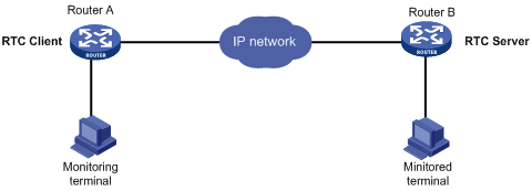
TCP or UDP one-to-one transparent transmission
Figure 1 shows a typical network diagram for the one-to-one transparent transmission. Router A initiates a monitoring request to access the data on the monitored terminal. Router B receives the monitoring request and sends the data of the monitored terminal to Router A. TCP RTC transparent transmission can ensure high reliability of the data transmitted, but it has a certain forwarding delay. Because voice service does not require high reliability, the UDP RTC transparent transmission is mainly applied to voice transmission.
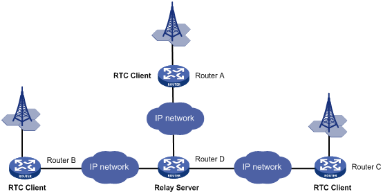
TCP many-to-one transparent transmission
Some terminal devices, such as radars, need to share data with one another. RTC terminal access provides many-to-one relay forwarding based on TCP. Routers connecting these terminals are connected to one relay server, which forwards data received from a router to other routers in the same group.
Figure 2 Network diagram
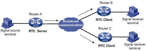
UDP one-to-many transparent transmission
UDP one-to-many transparent transmission is mainly applied to signal synchronization for unidirectional broadcast communication links. Figure 3 shows a typical network diagram for this type of transmission.
The UDP one-to-many transparent transmission procedure takes the following steps:
1. The signal source terminal sends data.
2. The RTC server sends the data to all RTC clients.
3. The RTC clients forward the data to the signal receiver terminals and do not respond to the RTC server.
RTC terminal access feature list
The following table lists the features supported by RTC terminal access. "All" in this table means that the feature is supported by all RTC access types, which include the following:
· TCP_11_Client (RTC TCP one-to-one client).
· TCP_11_Server (RTC TCP one-to-one server).
· TCP_N1_Server (relay server).
· UDP_11_Client (RTC UDP one-to-one client).
· UDP_11_Server (RTC UDP one-to-one server).
· UDP_1N_Server (RTC UDP one-to-many server).
|
Feature |
Supported by |
Description |
|
TCP_11_Client |
N/A |
|
|
TCP_11_Client |
N/A |
|
|
TCP_11_Client, TCP_11_Server, |
N/A |
|
|
TCP_11_Client |
N/A |
|
|
TCP_11_Client, TCP_11_Server, |
N/A |
|
|
TCP_11_Client |
N/A |
|
|
TTCP_11_Client, TCP_11_Server, TCP_N1_Server |
N/A |
|
|
TTCP_11_Client, TCP_11_Server, TCP_N1_Server |
N/A |
|
|
TCP_11_Client, TCP_11_Server, TCP_11_Server |
N/A |
|
|
TCP_11_Client, TCP_11_Server, UDP_11_Client, UDP_11_Server |
N/A |
|
|
TCP_11_Client, TCP_11_Server, TCP_N1_Server |
N/A |
|
|
Access types supporting synchronous terminals |
N/A |
|
|
All |
N/A |
|
|
Information debugging |
All |
For more information, see Terminal Access Debugging Command Manual. |
RTC terminal access features
Source address binding
This function specifies the source IP address of the TCP connection initiated from the router. You can use this function for the following purposes:
· For stable status—Use the IP address of a stable interface, for example, a loopback interface or a dialer interface, as the TCP source IP address.
· For security or some other reason—Specify a TCP source IP address to hide the IP address of the physical interface that is used in the upstream TCP connection.
Make sure the receiver and the interface whose IP address is used as the TCP source address can reach each other.
Fast VTY service switching
In RTC terminal access, each terminal is logically divided into eight virtual type terminals (VTYs). Each VTY can be configured to correspond to a service, which is also known as an application. On a terminal, you can press the hotkey to bring up the VTY switching menu and select a VTY.
Connection idle timeout
The initiator and receiver are automatically disconnected from each other when the following conditions are met:
· A connection idle timeout has been set.
· No data is transmitted between the initiator and receiver during the connection idle timeout period.
Automatic link establishment
You can enable this function and configure the automatic link establishment time in terminal template view. When the terminal is successfully connected to the initiator, the initiator automatically establishes a TCP connection to the receiver after the specified auto establishment time.
If this function is disabled, the initiator establishes a TCP connection to the receiver only when you enter a character on the terminal.
Automatic link teardown
You can enable this function and configure the automatic teardown time for the terminal in terminal template view. When the terminal and the initiator are disconnected from each other, the terminal enters down state. After the automatic teardown time, the initiator automatically tears down the TCP connection to the receiver. The TCP connection always remains active if the automatic link teardown function is disabled.
Terminal reset
When a terminal fails to communicate with the receiver, you can re-establish communication by pressing the terminal reset hotkey on the terminal. The initiator will disconnect and then re-establish the TCP connection with the receiver.
TCP parameter configuration
TCP buffers store the data exchanged between the initiator and receiver. You can set the following TCP connection parameters:
· Receive buffer size.
· Send buffer size.
· Non-delay attribute.
· Keepalive interval and number.
Terminal buffer parameter configuration
· Whether to clear the receive buffer before receiving data.
· Receive buffer size.
· Send buffer threshold.
· Maximum size of data to be sent to the terminal at one time.
RTC terminal authentication
Terminal access VPN instances
TCP NODELAY
In TCP many-to-one or TCP one-to-one transparent transmission mode, the RTC client and the RTC server use the Nagle algorithm to prevent network congestion caused by a large number of TCP packets. For more information, see RFC 896.
The Nagle algorithm also causes time delay during TCP packet transmission, especially for interactive applications. The RTC client and the RTC server allow you to disable the Nagle algorithm by setting the TCP_NODELAY option.
Link backup
One terminal or two terminals can connect to two synchronous serial interfaces of a router through two links. To configure backup between the two links, you can configure the two synchronous serial interfaces as primary and backup interfaces for the terminal access. When the primary interface is operating correctly, the router and the terminal communicate through the primary interface. When the primary interface fails or when the number of cyclic redundancy check errors on the primary interface reaches the upper threshold, the backup interface takes over. The primary interface takes over again when it recovers from a failure condition.
Compatibility mode support
RTC terminal access supports the following data transmission mode: characteristic mode and compatibility mode. The RTC server and the RTC client must operate in the same data transmission mode.
Devices running Comware 3 or Comware 5 can operate only in characteristic mode or compatibility mode. The mode is automatically set and is not user configurable.
Devices running Comware 7 can operate in either characteristic or compatibility mode, depending on your configuration. The default mode is characteristic mode.
RTC terminal access specifications
RTC terminal access initiator specifications
|
Item |
Specification |
|
Maximum number of TTYs |
255 This number is subject to the number of router interfaces available for terminal access. |
|
Maximum number of VTYs supported by each TTY |
8 |
|
Interface types supported by RTC terminal access |
Asynchronous serial interface Synchronous/asynchronous serial interface |
|
Terminal emulation type |
VT100 and VT200 |
|
Terminal baud rate |
300 bps to 115200 bps |
|
Access types supporting asynchronous terminals |
TCP_11_Client |
|
Access types supporting synchronous terminals |
UDP_11_Client |
RTC terminal access receiver specifications
|
Item |
Specification |
|
Maximum number of TTYs |
255 This number is subject to the number of router interfaces available for terminal access. |
|
Maximum number of VTYs supported by each TTY |
8 |
|
Maximum number of remote terminals supported by UDP_1N_Server |
10 |
|
Access types supporting asynchronous terminals |
TCP_11_Server, TCP_N1_Server |
|
Access types supporting synchronous terminals |
UDP_11_Server, UDP_1N_Server, TCP_N1_Server |
Relay server specifications
|
Item |
Specification |
|
Maximum number of forwarding groups supported by a TCP_N1_Server |
64 |
|
Maximum number of TCP_11_Clients supported by each forwarding group of a TCP_N1_Server |
10 |
Terminal templates
Most of the important settings of the RTC terminal system are configured in terminal templates on a router. The templates are applied to corresponding interfaces (such as an asynchronous serial interface). The router then creates TTYs and VTYs according to the template configurations. Only one template can be applied to an interface.
Restrictions: Hardware compatibility with RTC terminal access
|
Hardware |
RTC terminal access compatibility |
|
MSR810, MSR810-W, MSR810-W-DB, MSR810-LM, MSR810-W-LM, MSR810-10-PoE, MSR810-LM-HK, MSR810-W-LM-HK, MSR810-LMS-EA |
No |
|
MSR810-LMS, MSR810-LUS |
No |
|
MSR2600-6-X1, MSR2600-10-X1 |
No |
|
MSR 2630 |
Yes |
|
MSR3600-28, MSR3600-51 |
Yes |
|
MSR3600-28-SI, MSR3600-51-SI |
No |
|
MSR3600-28-X1, MSR3600-28-X1-DP, MSR3600-51-X1, MSR3600-51-X1-DP |
Yes |
|
MSR3610-I-DP, MSR3610-IE-DP |
No |
|
MSR3610-X1, MSR3610-X1-DP, MSR3610-X1-DC, MSR3610-X1-DP-DC |
Yes |
|
MSR 3610, MSR 3620, MSR 3620-DP, MSR 3640, MSR 3660 |
Yes |
|
MSR3610-G, MSR3620-G |
Yes |
Restrictions and guidelines: RTC terminal access configuration
If you modify a template that has been applied to an interface, use the update changed-config command to update the configuration.
RTC terminal access tasks at a glance
To configure RTC terminal access, configure the initiator and the receiver as required.
To configure RTC terminal access, perform the following tasks:
· Configuring asynchronous TCP one-to-one transmission
? Configuring the asynchronous TCP RTC one-to-one initiator (TCP_11_Client)
? Configuring the asynchronous TCP RTC one-to-one receiver (TCP_11_Server)
· Configuring the TCP RTC many-to-one relay server (TCP_N1_Server)
· Configuring synchronous UDP one-to-one transmission
? Configuring the synchronous UDP RTC one-to-one initiator (UDP_11_Client)
? Configuring the synchronous UDP RTC one-to-one receiver (UDP_11_Server)
· Configuring the synchronous UDP RTC one-to-many receiver (UDP_1N_Server)
Configuring the asynchronous TCP RTC one-to-one initiator (TCP_11_Client)
About the asynchronous TCP RTC one-to-one initiator
The initiator is a TCP_11_Client connected to the monitoring device. The receiver is a TCP_11_Server connected to the monitored device. The TCP_11_Client can initiate a connection request to the TCP_11_Server at any time to obtain the data of the monitored device.
Asynchronous TCP RTC one-to-one initiator tasks at a glance
To configure the asynchronous TCP RTC one-to-one initiator, perform the following tasks:
1. Enabling terminal access on the router
2. (Optional) Configuring a terminal template
3. Configuring a TTY user line
4. Applying the terminal template to an interface
Enabling terminal access on the router
1. Enter system view.
system-view
2. Enable terminal access on the router.
rta server enable
By default, terminal access on the router is disabled.
3. (Optional.) Configure the global source IP address for TCP connections.
rta source-ip ip-address
By default, no global source IP address for TCP connections is configured and the router uses the outbound interface's IP address as the TCP source address.
Configuring a terminal template
1. Enter system view.
system-view
2. Create a terminal template and enter terminal template view.
rta template template-name
3. Create a TCP RTC client VTY.
vty vty-number rtc-client remote ip-address port-number [ source source-ip ]
After this configuration, the template cannot be configured with any RTC server VTYs.
The port number configured for the RTC client VTY must be the same as the listening port number configured on the RTC server. The source IP address, if configured, has priority over the global TCP source address for the terminal.
4. (Optional.) Configure the timer for the TCP RTC client VTY.
? Configure the automatic link teardown time.
auto-close time
By default, the automatic link teardown time is 0 seconds, which indicates that no automatic link teardown will be performed.
? Configure the automatic link establishment time.
auto-link time
By default, the automatic link establishment time is 0 seconds, which indicates that no automatic link establishment will be performed.
? Configure the TCP connection idle timeout time.
idle-timeout seconds
By default, the TCP connection idle timeout time is 0 seconds, which indicates that the connection never times out.
5. (Optional.) Bind a VPN instance to the template.
bind vpn-instance vpn-instance-name
By default, the template is not bound with any VPN instance.
This command is used when the RTC client is also acting as an MPLS PE router. This feature enables the RTC client to receive terminal access packets from multiple VPNs and initiate connection requests.
6. (Optional.) Configuring the terminal buffer.
? Configure the router not to clear the terminal buffer after a TCP connection is established.
driverbuf save
By default, the router clears the terminal receive buffer after a TCP connection is established.
? Configure the terminal receive buffer size.
driverbuf size size
By default, the terminal receive buffer size is 8 KB.
? Configure the maximum size of data sent to a terminal at one time.
sendbuf bufsize size
By default, the maximum size of data sent to a terminal at one time is 500 bytes.
? Configure the terminal send buffer threshold.
sendbuf threshold value
By default, no terminal send buffer threshold is configured.
7. (Optional.) Configure the terminal hotkey
? Optional.) Set the terminal reset hotkey.
resetkey ascii-code&<1-3>
By default, no terminal reset hotkey is configured.
? Configure the VTY switching hotkey.
vty vty-number hotkey ascii-code&<1-3>
By default, no VTY switching hotkey is configured.
The ASCII value of the hotkey must be different from the ASCII value of any other hotkey configured on the device. In addition, using the hotkey may not get a fast response when the terminal display is busy.
8. (Optional.) Configure TCP parameters.
tcp { recvbuf-size recvsize | sendbuf-size sendsize | nodelay | keepalive time count }
By default:
? The receive buffer size is 2048 bytes.
? The send buffer size is 2048 bytes.
? Delay is enabled.
? The keepalive interval is 50 seconds.
? The keepalive number is 3.
This command takes effect only after a TCP connection is re-established.
9. (Optional.) Configure the password for VTY authentication.
vty vty-number password { simple | cipher } string
By default, no password for VTY authentication is configured.
To implement terminal access authentication, you must configure terminal access authentication on both the RTC server and the RTC client. The authentication passwords must be identical for the authentication to succeed.
10. Update the configuration.
update changed-config
If you modify a terminal template that has been applied to an interface, use this command to apply the most recent configuration. Executing this command will disconnect connections and re-establish connections. Make sure critical services are not affected.
Configuring a TTY user line
1. Enter system view.
system-view
2. Enter TTY user line view.
line { first-num1 [ last-num1 ] | tty first-num2 [ last-num2 ] }
For more information about the line command, see Fundamentals Command Reference.
3. Disable terminal service for the user line.
undo shell
By default, the terminal service is enabled on all user lines.
Disable the terminal service for the current user line before applying the terminal template to an interface.
For more information about the shell command, see Fundamentals Command Reference.
4. Enable software flow control of data for the user line.
flow-control software
By default, the hardware flow control mode is used.
Applying the terminal template to an interface
1. Enter system view.
system-view
2. Enter interface view.
interface interface-type interface-number
The interface type must be supported by RTC terminal access. Synchronous and asynchronous interfaces are supported.
3. Configure the operating mode or protocol type for the interface.
? Specify the operating mode as flow for an asynchronous serial interface.
async mode flow
By default, an asynchronous serial interface operates in the protocol mode.
For more information about the async-mode command, see Interface Command Reference.
? Specify the protocol type as STLP for a synchronous serial interface.
link-protocol stlp
By default, a synchronous serial interface operates in the PPP protocol mode.
4. Apply the template to the interface.
rta terminal template-name terminal-number
By default, no template is applied to the interface.
Configuring the asynchronous TCP RTC one-to-one receiver (TCP_11_Server)
Asynchronous TCP RTC one-to-one receiver tasks at a glance
To configure the asynchronous TCP RTC one-to-one receiver, perform the following tasks:
1. Enabling terminal access on the router
2. (Optional.) Configuring a terminal template
3. Configuring a TTY user line
4. Applying the terminal template to an interface
Enabling terminal access on the router
1. Enter system view.
system-view
2. Enable terminal access on the router.
rta server enable
By default, terminal access on the router is disabled.
3. Configure the global source IP address for TCP connections.
rta source-ip ip-address
By default, no global source IP address for TCP connections is configured and the router uses the outbound interface's IP address as the TCP source address.
4. Configure the listening port.
rta rtc-server listen-port port-number
By default, no listening port is configured.
This listening port number must be the same as the port number configured on the RTC client.
Configuring a terminal template
1. Enter system view.
system-view
2. Create a terminal template and enter terminal template view.
rta template template-name
3. Create a TCP RTC server VTY.
vty vty-number rtc-server remote ip-address terminal-number
After this configuration, the template cannot be configured with any RTC client VTYs.
The terminal-number argument of the vty rtc-server remote command configured on the RTC server must be the same as the terminal-number argument of the rta terminal command configured on the RTC client. Otherwise, no TCP connection can be established.
Each VTY of the RTC server must correspond to a different RTC client.
4. (Optional.) Configure the timer for the TCP RTC server VTY.
? Configure the automatic link teardown time.
auto-close time
By default, the automatic link teardown time is 0 seconds, which indicates that no automatic link teardown is performed.
? Configure the TCP connection idle timeout time.
idle-timeout seconds
By default, the TCP connection idle timeout time is 0 seconds, which indicates that the connection never times out.
5. (Optional.) Bind a VPN instance to the template.
bind vpn-instance vpn-instance-name
By default, the template is not bound with any VPN instance.
6. (Optional.) Configuring the terminal buffer.
? Configure the router to not clear the terminal buffer after a TCP connection is established.
driverbuf save
By default, the router clears the terminal receive buffer after a TCP connection is established.
? Configure the terminal receive buffer size.
driverbuf size size
By default, the terminal receive buffer size is 8 KB.
? Configure the maximum size of data sent to a terminal at one time.
sendbuf bufsize size
By default, the maximum size of data sent to a terminal at one time is 500 bytes.
? Configure the terminal send buffer threshold.
sendbuf threshold value
By default, no terminal send buffer threshold is configured.
7. (Optional.) Configure TCP parameters.
tcp { recvbuf-size recvsize | sendbuf-size sendsize | nodelay | keepalive time count }
By default:
? The receive buffer size is 2048 bytes.
? The send buffer size is 2048 bytes.
? Delay is enabled.
? The keepalive interval is 50 seconds.
? The keepalive number is 3.
This command takes effect only after a TCP connection is re-established.
8. (Optional.) Configure the password for VTY authentication.
vty vty-number password { simple | cipher } string
By default, no password for VTY authentication is configured.
To implement terminal access authentication, you must configure terminal access authentication on both the RTC server and the RTC client, and the authentication passwords must be identical for the authentication to succeed.
9. (Optional.) Update the configuration.
update changed-config
If you modify a terminal template that has been applied to an interface, use this command to apply the most recent configuration. Executing this command will disconnect connections and re-establish connections. Make sure critical services are not affected.
Configuring a TTY user line
1. Enter system view.
system-view
2. Enter TTY user line view.
line { first-num1 [ last-num1 ] | tty first-num2 [ last-num2 ] }
For more information about the line command, see Fundamentals Command Reference.
3. Disable terminal service for the user line.
undo shell
By default, the terminal service is enabled on all user lines.
Disable the terminal service for the current user line before applying the terminal template to an interface.
For more information about the shell command, see Fundamentals Command Reference.
4. Enable software flow control of data for the user line.
flow-control software
By default, the hardware flow control mode is used.
For more information about the flow-control command, see Fundamentals Command Reference.
Applying the terminal template to an interface
1. Enter system view.
system-view
2. Enter interface view.
interface interface-type interface-number
The interface type must be supported by RTC terminal access. Synchronous and asynchronous interfaces are supported.
3. Configure the operating mode or protocol type for the interface.
? For an asynchronous serial interface, specify the operating mode as flow:
async mode flow
By default, an asynchronous serial interface operates in the protocol mode.
For more information about the async-mode command, see Interface Command Reference.
? For a synchronous serial interface, specify the protocol type as STLP:
link-protocol stlp
By default, a synchronous serial interface operates in the PPP protocol mode.
4. Apply the template to the interface.
rta terminal template-name terminal-number
Configuring the TCP RTC many-to-one relay server (TCP_N1_Server)
About the TCP RTC many-to-one relay server
The initiators are TCP_11_Clients, which are connected to monitoring devices. The receiver is a relay server (TCP_N1_Server) which is not connected to any monitored device.
Procedure
1. Enter system view.
system-view
2. Enable relay forwarding.
rta relay enable
By default, relay forwarding is disabled.
3. Configure a TCP listening port.
rta relay listen-port port-number
By default, no TCP is configured.
4. (Optional.) Set the send buffer size and receive buffer size for TCP connections.
rta relay tcp { recvbuf-size recvbuff-size | sendbuf-size sendbuff-size }
By default, the send buffer size and the receive buffer size for TCP connections are 2048 bytes.
As a best practice, use the default values. An improper send buffer size or receive buffer size affects data forwarding efficiency and might cause system overload.
5. (Optional.) Configure the keepalive attributes for TCP connections between the relay server and a client.
rta relay tcp keepalive time count
By default, the keepalive interval is 50 seconds and the keepalive number is 3.
The TCP keepalive detection configuration takes effect immediately. Do not decrease the keepalive interval if the keepalive number is 1. A shorter keepalive interval might cause the device to disconnect all clients.
6. (Optional.) Set the forward buffer size for each RTC client.
rta relay buffer-size buffer-size
By default, the forward buffer size for an RTC client is 8 KB.
A larger forward buffer consumes more memory.
7. (Optional.) Enable the TCP_NODELAY function.
rta relay tcp nodelay
By default, the TCP_NODELAY function is disabled.
Configuring the synchronous UDP RTC one-to-one initiator (UDP_11_Client)
About the synchronous UDP RTC one-to-one initiator
The initiator is a UDP_11_Client, which is connected to the monitoring device through a synchronous serial interface. The receiver is a UDP_11_Server, which is connected to the monitored device through a synchronous serial interface. The initiator can establish a UDP connection with the receiver at any time to obtain data.
Enabling terminal access on the router
1. Enter system view.
system-view
2. Enable terminal access.
rta server enable
By default, terminal access is disabled.
Configuring a terminal template
1. Enter system view.
system-view
2. Create a terminal template and enter terminal template view.
rta template template-name
3. Create a UDP RTC client VTY.
vty vty-number rtc-client remote ip-address remote-port remote-port-number udp [ local-port local-port-number ] [ source source-ip-address ]
After this configuration, you cannot configure VTYs of other types in the template.
Applying the terminal template to an interface
1. Enter system view.
system-view
2. Enter the view of the primary interface.
interface interface-type interface-number
3. Configure the protocol type of the synchronous serial interface as STLP.
link-protocol stlp
By default, a synchronous serial interface operates in the PPP protocol mode.
4. Apply the template to the primary interface.
rta terminal template-name terminal-number
5. (Optional.) Apply the template to the backup interface.
rta terminal template-name terminal-number backup
The template-name and terminal-number arguments of the rta terminal backup command must be the same as those of the rta terminal command.
Configuring the synchronous UDP RTC one-to-one receiver (UDP_11_Server)
Enabling terminal access on the router
1. Enter system view.
system-view
2. Enable terminal access.
rta server enable
Configuring a terminal template
1. Enter system view.
system-view
2. Create a terminal template and enter terminal template view.
rta template template-name
3. Create a UDP RTC server VTY.
vty vty-number rtc-server remote [ ip-address remote-port remote-port-number ] udp local-port local-port-number [ source source-ip-address ]
After this configuration, you cannot configure VTYs of other types in the template.
Each VTY of the RTC server corresponds to a different RTC client.
Applying the terminal template to an interface
1. Enter system view.
system-view
2. Enter the view of the primary interface
interface interface-type interface-number
3. Configure the protocol type of the synchronous serial interface as STLP.
link-protocol stlp
By default, a serial interface operates in PPP protocol mode.
4. Apply the template to the primary interface.
rta terminal template-name terminal-number
5. (Optional.) Configure the protocol type of the synchronous serial interface as STLP.
link-protocol stlp
By default, a synchronous serial interface operates in PPP protocol mode.
6. (Optional.) Apply the template to the backup interface.
rta terminal template-name terminal-number backup
The template-name and terminal-number arguments of the rta terminal backup command must be the same as those of the rta terminal command.
Configuring the synchronous UDP RTC one-to-many receiver (UDP_1N_Server)
About the synchronous UDP RTC one-to-many receiver
The initiator is a UDP_11_Client, which is connected to the monitoring device through a synchronous serial interface. The receiver is a UDP_1N_Server, which is connected to the monitored device through a synchronous serial interface. An initiator can establish a UDP connection with a receiver at any time to obtain data. Multiple initiators are connected to a receiver, and the receiver sends data from a monitored device to all initiators simultaneously.
Enabling terminal access on the router
1. Enter system view.
system-view
2. Enable terminal access.
rta server enable
3. Create a terminal template and enter terminal template view.
rta template template-name
4. Create a one-to-many UDP RTC server VTY.
vty vty-number rtc-multipeer [ ip-address ] port-number
After this configuration, you cannot configure VTYs of other types of in the template.
5. Configure the client list.
rtc-multipeer vty-number remote ip-address port-number
By default, no client is configured.
You must create a UDP_1N_Server VTY before performing this configuration. You can configure up to ten clients for a VTY.
Applying the terminal template to an interface
1. Return to system view.
quit
2. Enter the view of the primary interface.
interface interface-type interface-number
The interface type must be supported by terminal access.
3. Configure the protocol type of the synchronous serial interface as STLP.
link-protocol stlp
By default, a synchronous serial interface operates in PPP protocol mode.
4. Apply the template to the primary interface.
rta terminal template-name terminal-number
5. ((Optional.) Apply the template to the backup interface.
rta terminal template-name terminal-number backup
The template-name and terminal-number arguments of the rta terminal backup command must be the same as those of the rta terminal command.
Display and maintenance commands for RTC terminal access
Execute displays commands in any view and reset commands in user view.
|
Task |
Command |
|
Display terminal access information. |
display rta { all | statistics | terminal-number { vty-number | brief | detail | statistics } } |
|
Display states of all RTC client connections accepted by a relay server. |
display rta relay status |
|
Display the forwarding statistics of a relay server. |
display rta relay statistics |
|
Clear statistics for a terminal. |
reset rta statistics terminal-number |
|
Clear the packet statistics for clients connected to the relay server. |
reset rta relay statistics |
|
Disconnect client connections from a relay server. |
rta relay disconnect { server-id client-id | all } |
RTC terminal access configuration examples
Example: Configuring asynchronous TCP RTC one-to-one
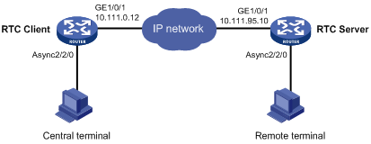
Network configuration
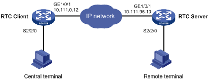
As shown in Figure 4, the RTC client and the RTC server are connected to the central terminal device and the remote terminal device through Async 2/2/0.
Configure the RTC client and the RTC server to enable the central terminal to monitor the remote terminal:
· Set the listening number of the RTC server to 9000.
· Set the terminal number to 1 on both the RTC client and the RTC server.
Procedure
1. Configure the RTC server:
# Enable terminal access.
<Sysname> system-view
[Sysname] rta server enable
# Set the listening port of the server.
[Sysname] rta rtc-server listen-port 9000
# Create a terminal template and enter terminal template view.
[Sysname] rta template rtcserver
# Configure the VTY.
[Sysname-rta-template-rtcserver] vty 0 rtc-server remote 10.111.0.12 1
[Sysname-rta-template-rtcserver] vty 0 password simple 123
[Sysname-rta-template-rtcserver] quit
# Apply the template to the interface.
[Sysname] interface async 2/2/0
[Sysname-Async2/2/0] async mode flow
[Sysname-Async2/2/0] rta terminal rtcserver 1
[Sysname-Async2/2/0] quit
2. Configure the RTC client:
# Enable terminal access.
<Sysname> system-view
[Sysname] rta server enable
# Create a terminal template and enter terminal template view.
[Sysname] rta template rtcclient
# Configure the VTY.
[Sysname-rta-template-rtcclient] vty 0 rtc-client remote 10.111.95.10 9000
[Sysname-rta-template-rtcclient] vty 0 password simple 123
[Sysname-rta-template-rtcclient] quit
# Apply the template to the interface.
[Sysname] interface async 2/2/0
[Sysname-Async2/2/0] async mode flow
[Sysname-Async2/2/0] rta terminal rtcclient 1
[Sysname-Async2/2/0] quit
Verifying the configuration
# Send an instruction from the central terminal to the remote terminal.
# Check that the remote terminal can receive the instruction, and check that the central terminal can receive the requested data from the remote terminal.
Example: Configuring synchronous TCP RTC one-to-one
Network configuration
As shown in Figure 5, the RTC client and the RTC server are connected to the central terminal device and the remote terminal device through synchronous serial interface Serial 2/2/0.
Configure the RTC client and the RTC server to enable the central terminal to monitor the remote terminal:
· Set the listening number of the RTC server to 9000.
· Set the terminal number to 1 on both the RTC client and the RTC server.
Procedure
1. Configure the RTC server:
# Enable terminal access.
<Sysname> system-view
[Sysname] rta server enable
# Set the listening port of the server.
[Sysname] rta rtc-server listen-port 9000
# Create a terminal template and enter terminal template view.
[Sysname] rta template rtcserver
# Configure the VTY.
[Sysname-rta-template-rtcserver] vty 0 rtc-server remote 10.111.0.12 1
[Sysname-rta-template-rtcserver] vty 0 password simple 123
[Sysname-rta-template-rtcserver] quit
# Apply the template to the interface.
[Sysname] interface serial 2/2/0
[Sysname-Serial2/2/0] link-protocol stlp
[Sysname-Serial2/2/0] rta terminal rtcserver 1
[Sysname-Serial2/2/0] quit
2. Configure the RTC client:
# Enable terminal access.
<Sysname> system-view
[Sysname] rta server enable
# Create a terminal template and enter terminal template view.
[Sysname] rta template rtcclient
# Configure the VTY.
[Sysname-rta-template-rtcclient] vty 0 rtc-client remote 10.111.95.10 9000
[Sysname-rta-template-rtcclient] vty 0 password simple 123
[Sysname-rta-template-rtcclient] quit
# Apply the template to the interface.
[Sysname] interface serial 2/2/0
[Sysname-Serial2/2/0] link-protocol stlp
[Sysname-Serial2/2/0] rta terminal rtcclient 1
[Sysname-Serial2/2/0] quit
Verifying the configuration
# Send an instruction from the central terminal to the remote terminal.
# Check that the remote terminal can receive the instruction, and check that the central terminal can receive the requested data from the remote terminal.
Example: Configuring asynchronous RTC VPNs
Network configuration
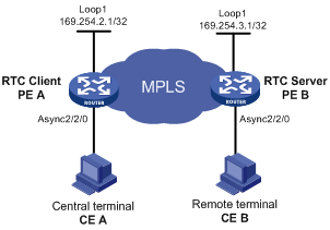
As shown in Figure 6, central terminal CE A in the monitoring center and remote terminal CE B are in MPLS L3VPN VPNA.
Configure the RTC server and the RTC client to enable the CE A to implementing real-time monitoring on CE B:
· Set the listening number of the RTC server to 9000.
· Set the terminal number to 2 on both PE A and PE B.
Procedure
1. Configure the RTC server:
# Configure MPLS L3VPN. For more information, see MPLS Configuration Guide.
# Bind Loopback 1 to VPNA.
<PEB> system-view
[PEB] interface loopback 1
[PEB-LoopBack1] ip binding vpn-instance vpna
[PEB-LoopBack1] ip address 169.254.3.1 32
[PEB-LoopBack1] quit
# Enable terminal access.
[PEB] rta server enable
# Configure the listening port number of the RTC server.
[PEB] rta rtc-server listen-port 9000
# Configure the terminal template.
[PEB] rta template rtcs
# Configure VTY 0 on the RTC server.
[PEB-rta-template-rtcs] vty 0 rtc-server remote 169.254.2.1 2
# Bind the VPN instance to the template.
[PEB-rta-template-rtcs] bind vpn-instance vpna
[PEB-rta-template-rtcs] quit
# Configure interface async 2/2/0.
[PEB] interface async 2/2/0
[PEB-Async2/2/0] async mode flow
[PEB-Async2/2/0] rta terminal rtcs 2
[PEB-Async2/2/0] quit
2. Configure the RTC client:
# Configure MPLS L3VPN. For more information, see MPLS Configuration Guide.
# Bind Loopback 1 to VPNA.
[PEA] interface loopback 1
[PEA-LoopBack1] ip address 169.254.2.1 32
[PEA-LoopBack1] ip binding vpn-instance vpna
[PEA-LoopBack1] quit
# Enable terminal access.
[PEA] rta server enable
# Configure a terminal template.
[PEA] rta template rtcc
# Configure VTY 0 on the RTC client.
[PEA-rta-template-rtcc] vty 0 rtc-client remote 169.254.3.1 9000
# Bind VPNA to the template.
[PEA-rta-template-rtcc] bind vpn-instance vpna
[PEA-rta-template-rtcc] quit
# Configure interface async 2/2/0.
[PEA] interface async 2/2/0
[PEA-Async2/2/0] async mode flow
[PEA-Async2/2/0] rta terminal rtcc 2
[PEA-Async2/2/0] quit
Verifying the configuration
# Send an instruction from CE A to CE B.
# Check that CE B can receive the instruction, and check that CE A can receive the requested data from CE B.
Example: Configuring asynchronous TCP RTC many-to-one relay
Network configuration
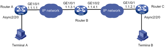
As shown in Figure 7, Router A and Router C act as TCP_11_Clients and Router B acts as the relay server TCP_N1_Server. The TCP_11_Clients are connected to the terminal devices through Async 2/2/0.
Configure the TCP_11_Clients and TCP_N1_Server to enable Terminal A and Terminal B to share data:
· Set the RTC listening number to 2000.
· Set the terminal number to 1 on both Router A and the Router C.
Procedure
1. Configure TCP_11_Client Router A:
# Enable terminal access.
<Sysname> system-view
[Sysname] rta server enable
# Create a terminal template and enter terminal template view.
[Sysname] rta template rtcclient
# Configure the VTY.
[Sysname-rta-template-rtcclient] vty 0 rtc-client remote 1.1.3.1 2000
[Sysname-rta-template-rtcclient] quit
# Apply the template to the interface.
[Sysname] interface async 2/2/0
[Sysname-Async2/2/0] async mode flow
[Sysname-Async2/2/0] rta terminal rtcclient 1
[Sysname-Async2/2/0] quit
2. Configure TCP_11_Client Router C:
# Enable terminal access.
<Sysname> system-view
[Sysname] rta server enable
# Create a terminal template and enter terminal template view.
[Sysname] rta template rtcclient
# Configure the VTY.
[Sysname-rta-template-rtcclient] vty 0 rtc-client remote 1.1.4.1 2000
[Sysname-rta-template-rtcclient] quit
# Apply the template to the interface.
[Sysname] interface async 2/2/0
[Sysname-Async2/2/0] async mode flow
[Sysname-Async2/2/0] rta terminal rtcclient 1
[Sysname-Async2/2/0] quit
3. Configure the relay server Router B:
# Enable terminal access relay.
<Sysname> system-view
[Sysname] rta relay enable
# Configure a listening port.
[Sysname] rta relay listen-port 2000
Verifying the configuration
# Check that Terminal A and Terminal B can receive data from each other.
Example: Configuring synchronous TCP RTC many-to-one relay
Network configuration
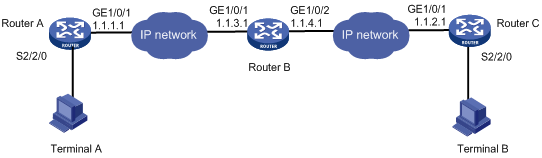
As shown in Figure 8, Router A and Router C act as TCP_11_Clients and Router B acts as the relay server TCP_N1_Server. The TCP_11_Clients are connected to the terminal devices through synchronous serial interface Serial 2/2/0.
Configure the TCP_11_Clients and TCP_N1_Server to enable Terminal A and Terminal B to share data:
· Set the RTC listening number to 2000.
· Set the terminal number to 1 on both Router A and the Router C.
Procedure
1. Configure TCP_11_Client Router A:
# Enable terminal access.
<Sysname> system-view
[Sysname] rta server enable
# Create a terminal template and enter terminal template view.
[Sysname] rta template rtcclient
# Configure the VTY.
[Sysname-rta-template-rtcclient] vty 0 rtc-client remote 1.1.3.1 2000
[Sysname-rta-template-rtcclient] quit
# Apply the template to the interface.
[Sysname] interface serial 2/2/0
[Sysname-Serial2/2/0] link-protocol stlp
[Sysname-Serial2/2/0] rta terminal rtcclient 1
[Sysname-Serial2/2/0] quit
2. Configure TCP_11_Client Router C:
# Enable terminal access.
<Sysname> system-view
[Sysname] rta server enable
# Create a terminal template and enter terminal template view.
[Sysname] rta template rtcclient
# Configure the VTY.
[Sysname-rta-template-rtcclient] vty 0 rtc-client remote 1.1.4.1 2000
[Sysname-rta-template-rtcclient] quit
# Apply the template to the interface.
[Sysname] interface serial 2/2/0
[Sysname-Serial2/2/0] link-protocol stlp
[Sysname-Serial2/2/0] rta terminal rtcclient 1
[Sysname-Serial2/2/0] quit
3. Configure the relay server Router B:
# Enable terminal access relay.
<Sysname> system-view
[Sysname] rta relay enable
# Configure a listening port.
[Sysname] rta relay listen-port 2000
Verifying the configuration
# Check that Terminal A and Terminal B can receive data from each other.
Example: Configuring UDP RTC one-to-one backup link
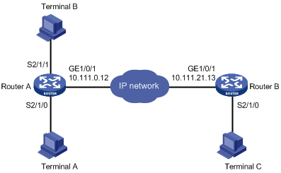
Network configuration
As shown in Figure 9, Router A acts as a UDP_11_Client, and Router B acts as a UDP_11_Server. Router A is connected to Terminal A through synchronous serial interface Serial 2/1/0 and Terminal B through synchronous serial interface Serial 2/1/1.
Configure the UDP RTC backup link function on the routers to enable Terminal A and its backup terminal B to monitor the remote terminal C:
· Configure Serial 2/1/0 as the primary interface and Serial 2/1/1 as the backup interface.
· Configure the RTC server to use a UDP port number of 3000 and the RTC client to use a UDP port number of 3001.
· Set the same terminal number to 1 on both the RTC client and the RTC server.
Procedure
1. Configure the UDP_11_Client Router A:
# Enable terminal access.
<Sysname> system-view
[Sysname] rta server enable
# Create a terminal template and enter terminal template view.
[Sysname] rta template rtcclient
# Configure the VTY.
[Sysname-rta-template-rtcclient] vty 0 rtc-client remote 10.111.21.13 remote-port 3000 udp local-port 3001 source 10.111.0.12
[Sysname-rta-template-rtcserver] quit
# Apply the template to the primary interface.
[Sysname] interface serial 2/1/0
[Sysname-Serial2/1/0] link-protocol stlp
[Sysname-Serial2/1/0] rta terminal rtcclient 1
[Sysname-Serial2/1/0] quit
# Apply the template to the backup interface.
[Sysname] interface serial 2/1/1
[Sysname-Serial2/1/1] link-protocol stlp
[Sysname-Serial2/1/1] rta terminal rtcclient 1 backup
[Sysname-Serial2/1/1] quit
2. Configure the UDP_11_Server Router B:
# Enable terminal access.
<Sysname> system-view
[Sysname] rta server enable
# Create a terminal template and enter terminal template view.
[Sysname] rta template rtcserver
# Configure the VTY.
[Sysname-rta-template-rtcserver] vty 0 rtc-server remote 10.111.0.12 remote-port 3001 udp local-port 3000 source 10.111.21.13
[Sysname-rta-template-rtcserver] quit
# Apply the template to the interface.
[Sysname] interface serial 2/1/0
[Sysname-Serial2/1/0] link-protocol stlp
[Sysname-Serial2/1/0] rta terminal rtcserver 1
[Sysname-Serial2/1/0] quit
Verifying the configuration
To verify the backup link function, follow these steps:
1. Send a connection request from Terminal A and Terminal B to Terminal C when both Serial 2/1/0 and Serial 2/1/1 on Router A are in up state.
Expected result: Terminal A can receive data from Terminal C. Terminal B cannot receive data from Terminal C.
2. Shut down Serial 2/1/0 on Router A and send a connection request from Terminal A and Terminal B.
Expected result: Terminal A cannot receive data from Terminal C. Terminal B can receive data from Terminal C.
3. Bring up Serial 2/1/0 on router A and send a connection request from Terminal A and Terminal B.
Expected result: Terminal A can receive data from Terminal C. Terminal B cannot receive data from Terminal C.
Example: Configuring UDP RTC one-to-many
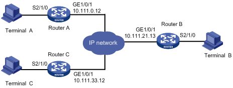
Network configuration
As shown in Figure 10, Router A and Router C act as UDP_11_Clients, and Router B acts as a UDP_1N_Server.
Configure Router A, Router B, and Router C to enable both Terminal A and Terminal C to receive data from Terminal B:
· Configure the RTC server to use a UDP port number of 3000 and the RTC client to use a UDP port number of 3001.
· Set the terminal number to 1 on both the RTC client and the RTC server.
Procedure
1. Configure the UDP_11_Client Router A:
# Enable terminal access.
<Sysname> system-view
[Sysname] rta server enable
# Create a terminal template and enter terminal template view.
[Sysname] rta template rtcclient
# Configure the VTY.
[Sysname-rta-template-rtcclient] vty 0 rtc-client remote 10.111.21.13 remote-port 3000 udp local-port 3001 source 10.111.0.12
[Sysname-rta-template-rtcserver] quit
# Apply the template to the primary interface.
[Sysname] interface serial 2/1/0
[Sysname-Serial2/1/0] link-protocol stlp
[Sysname-Serial2/1/0] rta terminal rtcclient 1
[Sysname-Serial2/1/0] quit
2. Configure the UDP_11_Client Router C:
# Enable terminal access.
<Sysname> system-view
[Sysname] rta server enable
# Create a terminal template and enter terminal template view.
[Sysname] rta template rtcclient
# Configure the VTY.
[Sysname-rta-template-rtcclient] vty 0 rtc-client remote 10.111.21.13 remote-port 3000 udp local-port 3001 source 10.111.33.12
[Sysname-rta-template-rtcserver] quit
# Apply the template to the interface.
[Sysname] interface Serial 2/1/0
[Sysname-Serial2/1/0] link-protocol stlp
[Sysname-Serial2/1/0] rta terminal rtcclient 1
[Sysname-Serial2/1/0] quit
3. Configure the UDP_1N_Server (Router B):
# Enable terminal access.
<Sysname> system-view
[Sysname] rta server enable
# Create a terminal template and enter terminal template view.
[Sysname] rta template rtcserver
# Configure the VTY.
[Sysname-rta-template-rtcserver] vty 0 rtc-multipeer 10.111.21.13 3000
# Configure the IP addresses and port numbers of the two initiators.
[Sysname-rta-template-rtcserver] rtc-multipeer 0 remote 10.111.0.12 3001
[Sysname-rta-template-rtcserver] rtc-multipeer 0 remote 10.111.33.12 3001
[Sysname-rta-template-rtcserver] quit
# Apply the template to the interface.
[Sysname] interface serial 2/1/0
[Sysname-Serial2/1/0] link-protocol stlp
[Sysname-Serial2/1/0] rta terminal rtcserver 1
[Sysname-Serial2/1/0] quit
Verifying the configuration
# Send data from Terminal B to Terminal A and Terminal C.
# Check that both Terminal A and Terminal C can receive the data.
Troubleshooting RTC terminal access
Failure to establish a terminal connection
Symptom
The terminal displays that the connection toggles between Established and Establishing state, and ultimately goes down.
Analysis
The initiator and receiver are not configured consistently. Most mistakes result from inconsistent configurations.
Solution
· Verify that the same application mode (many-to-one or one-to-one) is configured on both the initiator and the receiver.
· Verify that the initiator and receiver are configured consistently, and that the configurations comply with the parameter configuration conventions.
· Verify that the router IP address configured on the receiver is the bound IP address if the source address binding is configured on the initiator.
· Verify that the initiator and receiver can reach each other.
Terminal state is down after terminal access is enabled
Symptom
Terminal access is enabled by using the rta server enable command. However, the display rta command displays that the state of a powered terminal is Down.
Analysis
The asynchronous serial interface is configured with the undo modem command.
Terminal cable or converter failure occurs.
Solution
· Verify that the asynchronous serial interface is not configured with the undo modem command.
· Verify that the terminal cable is functional.
· Verify that the converter connecting the terminal and the router is wired correctly.