- Table of Contents
-
- 07-IP Multicast Configuration Guides
- 00-Preface
- 01-Multicast Overview
- 02-IGMP snooping configuration
- 03-PIM snooping configuration
- 04-Multicast VLAN configuration
- 05-Multicast routing and forwarding configuration
- 06-IGMP configuration
- 07-PIM configuration
- 08-MSDP configuration
- 09-Multicast VPN configuration
- 10-MLD snooping configuration
- 11-IPv6 PIM snooping configuration
- 12-IPv6 multicast VLAN configuration
- 13-IPv6 multicast routing and forwarding configuration
- 14-MLD configuration
- 15-IPv6 PIM configuration
- Related Documents
-
| Title | Size | Download |
|---|---|---|
| 07-PIM configuration | 885.53 KB |
Administrative scoping overview
Administrative scoping mechanism
Relationship between admin-scoped zones and the global-scoped zone
Relationship among PIM protocols
Configuration restrictions and guidelines
PIM-DM configuration task list
Enabling the state refresh feature
Configuring state refresh parameters
Configuring PIM-DM graft retry timer
PIM-SM configuration task list
Configuring multicast source registration
Configuring the switchover to SPT
Configuration restrictions and guidelines
BIDIR-PIM configuration task list
PIM-SSM configuration task list
Configuring the SSM group range
Configuring common PIM features
Common PIM feature configuration task list
Configuring a multicast source policy
Configuring a PIM hello policy
Configuring PIM hello message options
Setting the maximum size of a join or prune message
Enabling SNMP notifications for PIM
Setting a DSCP value for outgoing PIM messages
Displaying and maintaining PIM
PIM-SM non-scoped zone configuration example
PIM-SM admin-scoped zone configuration example
BIDIR-PIM configuration example
A multicast distribution tree cannot be correctly built
Multicast data is abnormally terminated on an intermediate router
An RP cannot join an SPT in PIM-SM
An RPT cannot be built or multicast source registration fails in PIM-SM
PIM overview
Protocol Independent Multicast (PIM) provides IP multicast forwarding by leveraging unicast static routes or unicast routing tables generated by any unicast routing protocol, such as RIP, OSPF, IS-IS, or BGP. PIM uses the underlying unicast routing to generate a multicast routing table without relying on any particular unicast routing protocol.
PIM uses the RPF mechanism to implement multicast forwarding. When a multicast packet arrives on an interface of the device, it undergoes an RPF check. If the RPF check succeeds, the device creates a multicast routing entry and forwards the packet. If the RPF check fails, the device discards the packet. For more information about RPF, see "Configuring multicast routing and forwarding."
PIM mode
Based on the implementation mechanism, PIM includes the following modes:
· Protocol Independent Multicast–Dense Mode (PIM-DM).
· Protocol Independent Multicast–Sparse Mode (PIM-SM).
· Bidirectional Protocol Independent Multicast (BIDIR-PIM).
· Protocol Independent Multicast Source-Specific Multicast (PIM-SSM).
In this document, a PIM domain refers to a network composed of PIM routers.
PIM-DM
PIM-DM uses the push mode for multicast forwarding, and is suitable for small-sized networks with densely distributed multicast members.
PIM-DM assumes that all downstream nodes want to receive multicast data from a source, so multicast data is flooded to all downstream nodes on the network. Branches without downstream receivers are pruned from the forwarding trees. When a pruned branch has new receivers, the graft mechanism turns the pruned branch into a forwarding branch.
In PIM-DM, the multicast forwarding paths for a multicast group constitutes a forwarding tree. The forwarding tree is rooted at the multicast source and has multicast group members as its "leaves." Because the forwarding tree consists of the shortest paths from the multicast source to the receivers, it is also called a "shortest path tree (SPT)."
Neighbor discovery
In a PIM domain, each PIM interface on a router periodically multicasts PIM hello messages to all other PIM routers (identified by the address 224.0.0.13) on the local subnet. Through the exchanging of hello messages, all PIM routers on the subnet determine their PIM neighbors, maintain PIM neighboring relationship with other routers, and build and maintain SPTs.
SPT building
The process of building an SPT is the flood-and-prune process:
1. In a PIM-DM domain, the multicast data from the multicast source S to the multicast group G is flooded throughout the domain. A router performs an RPF check on the multicast data. If the RPF check succeeds, the router creates an (S, G) entry and forwards the data to all downstream nodes on the network. In the flooding process, all the routers in the PIM-DM domain create the (S, G) entry.
2. The nodes without downstream receivers are pruned. A router that has no downstream receivers multicasts a prune message to all PIM routers on the subnet. When an upstream node receives the prune message, it removes the receiving interface from the (S, G) entry. In this way, the upstream stream node stops forwarding subsequent packets addressed to that multicast group down to this node.
|
|
NOTE: An (S, G) entry contains a multicast source address S, a multicast group address G, an outgoing interface list, and an incoming interface. |
A prune process is initiated by a leaf router. As shown in Figure 1, the router interface that does not have any downstream receivers initiates a prune process by sending a prune message toward the multicast source. This prune process goes on until only necessary branches are left in the PIM-DM domain, and these necessary branches constitute an SPT.

The pruned state of a branch has a finite holdtime timer. When the timer expires, multicast data is again forwarded to the pruned branch. The flood-and-prune cycle takes place periodically to maintain the forwarding branches.
Graft
A previously pruned branch might have new downstream receivers. To reduce the latency for resuming the forwarding capability of this branch, a graft mechanism is used as follows:
1. The node that needs to receive the multicast data sends a graft message to its upstream node, telling it to rejoin the SPT.
2. After receiving this graft message on an interface, the upstream node adds the receiving interface to the outgoing interface list of the (S, G) entry. It also sends a graft-ack message to the graft sender.
3. If the graft sender receives a graft-ack message, the graft process finishes. Otherwise, the graft sender continues to send graft messages at a graft retry interval until it receives an acknowledgment from its upstream node.
Assert
On a subnet with more than one multicast router, the assert mechanism shuts off duplicate multicast flows to the network. It does this by electing a unique multicast forwarder for the subnet.
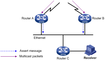
As shown in Figure 2, after Router A and Router B receive an (S, G) packet from the upstream node, they both forward the packet to the local subnet. As a result, the downstream node Router C receives two identical multicast packets. In addition, both Router A and Router B, on their downstream interfaces, receive a duplicate packet forwarded by the other. After detecting this condition, both routers send an assert message to all PIM routers (224.0.0.13) on the local subnet through the interface that received the packet. The assert message contains the multicast source address (S), the multicast group address (G), and the metric preference and metric of the unicast route/MBGP route/static multicast route to the multicast source. By comparing these parameters, either Router A or Router B becomes the unique forwarder of the subsequent (S, G) packets on the shared-media LAN. The comparison process is as follows:
1. The router with a higher metric preference to the multicast source wins.
2. If both routers have the same metric preference, the router with a smaller metric wins.
3. If both routers have the same metric, the router with a higher IP address on the downstream interface wins.
PIM-SM
PIM-DM uses the flood-and-prune cycles to build SPTs for multicast data forwarding. Although an SPT has the shortest paths from the multicast source to the receivers, it is built with a low efficiency. Therefore, PIM-DM is not suitable for large and medium-sized networks.
PIM-SM uses the pull mode for multicast forwarding, and it is suitable for large- and medium-sized networks with sparsely and widely distributed multicast group members.
PIM-SM assumes that no hosts need multicast data. A multicast receiver must express its interest in the multicast data for a multicast group before the data is forwarded to it. A rendezvous point (RP) is the core of a PIM-SM domain. Relying on the RP, SPTs and rendezvous point trees (RPTs) are established and maintained to implement multicast data forwarding. An SPT is rooted at the multicast source and has the RPs as its leaves. An RPT is rooted at the RP and has the receiver hosts as its leaves.
Neighbor discovery
PIM-SM uses the same neighbor discovery mechanism as PIM-DM does. For more information, see "Neighbor discovery."
DR election
A designated router (DR) is required on both the source-side network and receiver-side network. A source-side DR acts on behalf of the multicast source to send register messages to the RP. The receiver-side DR acts on behalf of the multicast receivers to send join messages to the RP.
PIM-DM does not require a DR. However, if IGMPv1 runs on any shared-media LAN in a PIM-DM domain, a DR must be elected to act as the IGMPv1 querier for the LAN. For more information about IGMP, see "Configuring IGMP."
|
|
IMPORTANT: IGMP must be enabled on the device that acts as the receiver-side DR. Otherwise, the receiver hosts attached to the DR cannot join any multicast groups. |
As shown in Figure 3, the DR election process is as follows:
1. The routers on the shared-media LAN send hello messages to one another. The hello messages contain the DR priority for DR election. The router with the highest DR priority is elected as the DR.
2. The router with the highest IP address wins the DR election under one of following conditions:
¡ All the routers have the same DR election priority.
¡ A router does not support carrying the DR priority in hello messages.
If the DR fails, its PIM neighbor lifetime expires and the other routers will initiate to elect a new DR.
RP discovery
An RP is the core of a PIM-SM domain. An multicast group can have only one RP for multicast forwarding, and an RP can be designated to multiple multicast groups.
RP selection
An RP can be statically configured or dynamically elected. The priorities of the static RP and the dynamic RP depend on whether the static RP is preferred when the static RP is configured.
· If the static RP is preferred, the static RP takes precedence over the dynamic RP. The dynamic RP takes services over only when the static RP fails.
· If the static RP is not preferred, the dynamic RP takes precedence over the static RP. The static RP takes services over only when the dynamic RP fails.
Static RPs
A static RP can avoid a single point of failure and save network bandwidth that is consumed by frequent communications between C-RPs and the BSR.
Dynamic RP election
Dynamic RP election is implemented through the BSR mechanism. BSR mechanism includes the following roles:
· Candidate-RPs (C-RPs)—An RP is dynamically elected from C-RPs to provide services to an multicast group.
· BSR—A BSR is the core of the administrative core of the PIM-SM domain. It is responsible for collecting and advertising RP information in the whole domain. An PIM-SM domain has only one BSR, and the BSR is elected from C-BSRs.
· Candidate-BSRs (C-BSRs)—Any devices in the PIM-SM domain can act as C-BSRs and the BSR is elected from the C-BSRs. Once the BSR fails, a new BSR is elected from the C-BSRs to avoid multicast traffic interruption.
|
|
NOTE: A device can act as a C-RP and a C-BSR at the same time. |
Figure 4 Information exchange between C-RPs and BSR
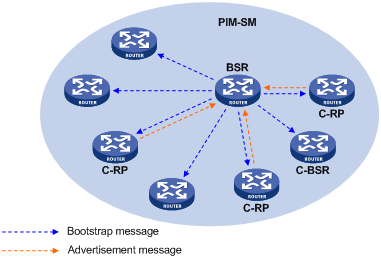
As shown in Figure 4, an RP is dynamically elected as follows:
1. Each C-BSR sends a bootstrap message (BSM) to other devices in the PIM-SM domain.
2. When a C-BSR receives a BSM from another C-BSR, it compares its own priority with the priority carried in the message. The C-BSR with a higher priority wins the BSR election. If a tie exists in the priority, the C-BSR with a higher IP address wins. The loser uses the winner's BSR address to replace its own BSR address and no longer regards itself as the BSR. The winner retains its own BSR address and continues to regard itself as the BSR.
3. Each C-RP periodically unicasts an advertisement message to the BSR. An advertisement message contains the IP address of the advertising C-RP and the multicast group range to which it is designated.
4. The BSR collects these advertisement messages and organizes the C-RP information into an RP-set, which is a database of mappings between multicast groups and RPs. The BSR encapsulates the RP-set information in the BSMs and advertises the BSMs to the entire PIM-SM domain.
5. All devices in the PIM-SM domain select an RP for an multicast group based on the following rules:
a. The C-RP that is designated to the smallest multicast group range wins.
b. If the C-RPs are designated to the same group ranges, the C-RP with the highest priority wins.
c. If the C-RPs have the same priority, the C-RP with the largest hash value wins. The hash value is calculated through the hash algorithm.
d. If the C-RPs have the same hash value, the C-RP with the highest IP address wins.
Anycast RP
PIM-SM requires only one active RP to serve each multicast group. If the active RP fails, the multicast traffic might be interrupted. The Anycast RP mechanism enables redundancy backup among RPs by configuring multiple RPs with the same IP address. A multicast source registers with the closest RP or a receiver joins the closest RP to implement source information synchronization.
Anycast RP has the following benefits:
· Optimal RP path—A multicast source registers with the closest RP to build an optimal SPT. A receiver joins the closest RP to build an optimal RPT.
· Redundancy backup among RPs—When an RP fails, the RP-related sources will register with the closest available RPs and the receiver-side DRs will join the closest available RPs. This provides redundancy backup among RPs.
Anycast RP is implemented in either of the following methods:
· Anycast RP through MSDP—In this method, you can configure multiple RPs with the same IP address for one multicast group and configure MSDP peering relationships between them. For more information about Anycast RP through MSDP, see "Configuring MSDP."
· Anycast RP through PIM-SM—In this method, you can configure multiple RPs for one multicast group and add them to an Anycast RP set. This method introduces the following concepts:
¡ Anycast RP set—A set of RPs that are designated to the same multicast group.
¡ Anycast RP member—Each RP in the Anycast RP set.
¡ Anycast RP member address—IP address of each Anycast RP member for communication among the RP members.
¡ Anycast RP address—IP address of the Anycast RP set for communication within the PIM-SM domain. It is also known as RPA.
As shown in Figure 5, RP 1, RP 2, and RP 3 are members of an Anycast RP set.
Figure 5 Anycast RP through PIM-SM
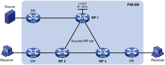
The following describes how Anycast RP through PIM-SM is implemented:
a. RP 1 receives a register message destined to RPA. Because the message is not from other Anycast RP members (RP 2 or RP 3), RP 1 considers that the register message is from the DR. RP 1 changes the source IP address of the register message to its own address and sends the message to the other members (RP 2 and RP 3).
If a router acts as both a DR and an RP, it creates a register message, and then forwards the message to the other RP members.
b. After receiving the register message, RP 2 and RP 3 find out that the source address of the register message is an Anycast RP member address. They stop forwarding the message to other routers.
In Anycast RP implementation, an RP must forward the register message from the DR to other Anycast RP members to synchronize multicast source information.
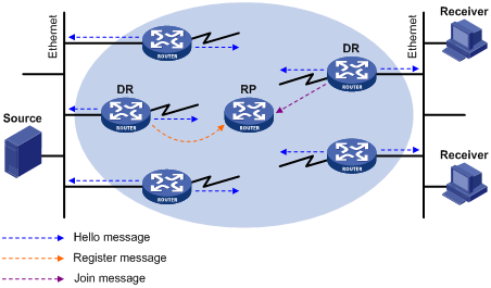
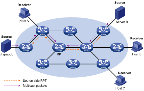
RPT building
Figure 6 RPT building in a PIM-SM domain
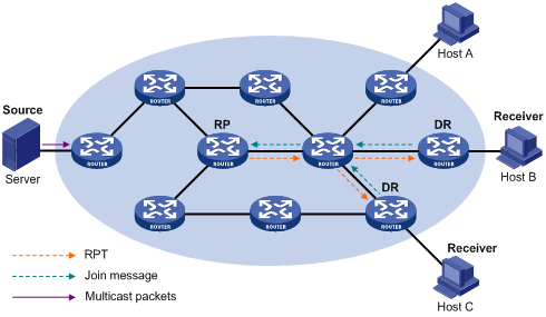
As shown in Figure 6, the process of building an RPT is as follows:
1. When a receiver wants to join the multicast group G, it uses an IGMP message to inform the receiver-side DR.
2. After getting the receiver information, the DR sends a join message, which travels hop by hop to the RP for the multicast group.
3. The routers along the path from the DR to the RP form an RPT branch. Each router on this branch adds to its forwarding table a (*, G) entry, where the asterisk (*) represents any multicast source. The RP is the root of the RPT, and the DR is a leaf of the RPT.
When the multicast data addressed to the multicast group G reaches the RP, the RP forwards the data to the DR along the established RPT, and finally to the receiver.
When a receiver is no longer interested in the multicast data addressed to the multicast group G, the receiver-side DR sends a prune message. The prune message goes hop by hop along the RPT to the RP. After receiving the prune message, the upstream node deletes the interface that connects to this downstream node from the outgoing interface list. At the same time, the upstream router checks for the existence of receivers for that multicast group. If no receivers for the multicast group exist, the router continues to forward the prune message to its upstream router.
Multicast source registration
The multicast source uses the registration process to inform an RP of its presence.
Figure 7 Multicast source registration
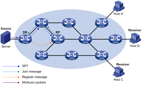
As shown in Figure 7, the multicast source registers with the RP as follows:
1. The multicast source S sends the first multicast packet to the multicast group G. When receiving the multicast packet, the source-side DR encapsulates the packet into a PIM register message and unicasts the message to the RP.
2. After the RP receives the register message, it decapsulates the register message and forwards the register message down to the RPT. Meanwhile, it sends an (S, G) source-specific join message toward the multicast source. The routers along the path from the RP to the multicast source constitute an SPT branch. Each router on this branch creates an (S, G) entry in its forwarding table.
3. The subsequent multicast data from the multicast source are forwarded to the RP along the established SPT. When the multicast data reaches the RP along the SPT, the RP forwards the data to the receivers along the RPT. Meanwhile, it unicasts a register-stop message to the source-side DR to prevent the DR from unnecessarily encapsulating the data.
Switchover to SPT
|
|
CAUTION: If the switch is an RP, disabling switchover to SPT might cause multicast traffic forwarding failures on the source-side DR. When disabling switchover to SPT, be sure you fully understand its impact on your network. |
In a PIM-SM domain, only one RP and one RPT provide services for a specific multicast group. Before the switchover to SPT occurs, the source-side DR encapsulates all multicast data in register messages and sends them to the RP. After receiving these register messages, the RP decapsulates them and forwards them to the receiver-side DR along the RPT.
Multicast forwarding along the RPT has the following weaknesses:
· Encapsulation and decapsulation are complex on the source-side DR and the RP.
· The path for a multicast packet might not be the shortest one.
· The RP might be overloaded by multicast traffic bursts.
To eliminate these weaknesses, PIM-SM allows an RP or the receiver-side DR to initiate the switchover to SPT when the RP or the DR receives the first multicast packet.
· The RP initiates the switchover to SPT.
When the RP receives the first multicast packet, it sends an (S, G) source-specific join message toward the multicast source. The routers along the path from the RP to the multicast source constitute an SPT. The subsequent multicast data is forwarded to the RP along the SPT without being encapsulated into register messages.
For more information about the switchover to SPT initiated by the RP, see "Multicast source registration."
· The receiver-side DR initiates the switchover to SPT.
When the receiver-side DR receives the first multicast packet, it initiates the switchover to SPT as follows:
a. The DR sends an (S, G) source-specific join message toward the multicast source. The routers along the path create an (S, G) entry in their forwarding table to constitute an SPT branch.
b. When the multicast packets reach the router where the RPT and the SPT branches, the router drops the multicast packets that travel along the RPT. It then sends a prune message with the RP bit toward the RP.
c. After receiving the prune message, the RP forwards it toward the multicast source (supposed only one receiver exists). Thus, the switchover to SPT is completed. The subsequent multicast packets travel along the SPT from the multicast source to the receiver hosts.
With the switchover to SPT, PIM-SM builds SPTs more economically than PIM-DM does.
Assert
PIM-SM uses a similar assert mechanism as PIM-DM does. For more information, see "Assert."
BIDIR-PIM
In some many-to-many applications, such as a multi-side video conference, multiple receivers of a multicast group might be interested in the multicast data from multiple multicast sources. With PIM-DM or PIM-SM, each router along the SPT must create an (S, G) entry for each multicast source, consuming a lot of system resources.
BIDIR-PIM addresses the problem. Derived from PIM-SM, BIDIR-PIM builds and maintains a bidirectional RPT, which is rooted at the RP and connects the multicast sources and the receivers. Along the bidirectional RPT, the multicast sources send multicast data to the RP, and the RP forwards the data to the receivers. Each router along the bidirectional RPT needs to maintain only one (*, G) entry, saving system resources.
BIDIR-PIM is suitable for a network with dense multicast sources and receivers.
Neighbor discovery
BIDIR-PIM uses the same neighbor discovery mechanism as PIM-SM does. For more information, see "Neighbor discovery."
RP discovery
BIDIR-PIM uses the same RP discovery mechanism as PIM-SM does. For more information, see "RP discovery." In BIDIR-PIM, an RPF interface is the interface toward an RP, and an RPF neighbor is the address of the next hop to the RP.
In PIM-SM, an RP must be specified with a real IP address. In BIDIR-PIM, an RP can be specified with a virtual IP address, which is called the "rendezvous point address (RPA)." The link corresponding to the RPA's subnet is called the "rendezvous point link (RPL)." All interfaces connected to the RPL can act as the RPs, and they back up one another.
DF election
On a subnet with multiple multicast routers, duplicate multicast packets might be forwarded to the RP. To address this issue, BIDIR-PIM uses a designated forwarder (DF) election mechanism to elect a unique DF for each RP on a subnet. Only the DFs can forward multicast data to the RP.
DF election is not necessary for an RPL.
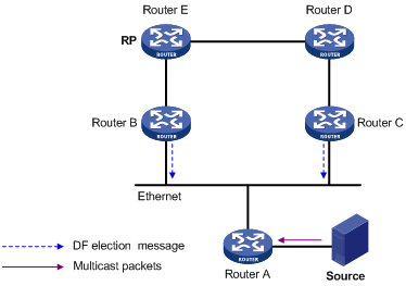
As shown in Figure 8, without the DF election mechanism, both Router B and Router C can receive multicast packets from Route A. They also can forward the packets to downstream routers on the local subnet. As a result, the RP (Router E) receives duplicate multicast packets.
With the DF election mechanism, once receiving the RP information, Router B and Router C multicast a DF election message to all PIM routers (224.0.0.13) to initiate a DF election process. The election message carries the RP's address, and the route preference and the metric of the unicast route or static multicast route to the RP. A DF is elected as follows:
1. The router with a higher route preference becomes the DF.
2. If the routers have the same route preference, the router with a lower metric becomes the DF.
3. If the routers have the same metric, the router with a higher IP address becomes the DF.
Bidirectional RPT building
Figure 9 RPT building at the receiver side
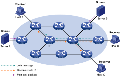
As shown in Figure 9, the process for building a receiver-side RPT is the same as the process for building an RPT in PIM-SM:
1. When a receiver wants to join the multicast group G, it uses an IGMP message to inform the directly connected router.
2. After receiving the message, the router sends a join message, which is forwarded hop by hop to the RP for the multicast group.
3. The routers along the path from the receiver's directly connected router to the RP form an RPT branch. Each router on this branch adds a (*, G) entry to its forwarding table.
After a receiver host leaves the multicast group G, the directly connected router multicasts a prune message to all PIM routers on the subnet. The prune message goes hop by hop along the reverse direction of the RPT to the RP. After receiving the prune message, an upstream node removes the interface that connects to the downstream node from the outgoing interface list. At the same time, the upstream router checks the existence of receivers for that multicast group. If no receivers for the multicast group exist, the router continues to forward the prune message to its upstream router.
Figure 10 RPT building at the multicast source side
As shown in Figure 10, the process for building a source-side RPT is relatively simple:
1. When a multicast source sends multicast packets to the multicast group G, the DF in each subnet unconditionally forwards the packets to the RP.
2. The routers along the path from the source's directly connected router to the RP constitute an RPT branch. Each router on this branch adds to its forwarding table a (*, G) entry.
After a bidirectional RPT is built, the multicast sources send multicast traffic to the RP along the source-side RPT. Then, the RP forwards the traffic to the receivers along the receiver-side RPT.
|
|
IMPORTANT: If a receiver and a multicast source are at the same side of the RP, the source-side RPT and the receiver-side RPT might meet at a node before reaching the RP. In this case, the multicast packets from the multicast source to the receiver are directly forwarded by the node, instead of by the RP. |
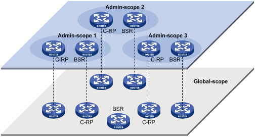
Administrative scoping overview
Typically, a PIM-SM domain or a BIDIR-PIM domain contains only one BSR, which is responsible for advertising RP-set information within the entire domain. The information about all multicast groups is forwarded within the network that the BSR administers. This is called the "non-scoped BSR mechanism."
Administrative scoping mechanism
To implement refined management, you can divide a PIM-SM domain or BIDIR-PIM domain into a global-scoped zone and multiple administratively-scoped zones (admin-scoped zones). This is called the "administrative scoping mechanism."
The administrative scoping mechanism effectively releases stress on the management in a single-BSR domain and enables provision of zone-specific services through private group addresses.
Admin-scoped zones are divided for multicast groups. Zone border routers (ZBRs) form the boundary of an admin-scoped zone. Each admin-scoped zone maintains one BSR for multicast groups within a specific range. Multicast protocol packets, such as assert messages and BSMs, for a specific group range cannot cross the boundary of the admin-scoped zone for the group range. Multicast group ranges that are associated with different admin-scoped zones can have intersections. However, the multicast groups in an admin-scoped zone are valid only within the local zone, and theses multicast groups are regarded as private group addresses.
The global-scoped zone maintains a BSR for the multicast groups that do not belong to any admin-scoped zones.
Relationship between admin-scoped zones and the global-scoped zone
The global-scoped zone and each admin-scoped zone have their own C-RPs and BSRs. These devices are effective only on their respective zones, and the BSR election and the RP election are implemented independently. Each admin-scoped zone has its own boundary. The multicast information within a zone cannot cross this boundary in either direction. You can have a better understanding of the global-scoped zone and admin-scoped zones based on geographical locations and multicast group address ranges.
· In view of geographical locations:
An admin-scoped zone is a logical zone for particular multicast groups. The multicast packets for such multicast groups are confined within the local admin-scoped zone and cannot cross the boundary of the zone.
Figure 11 Relationship in view of geographical locations
As shown in Figure 11, for the multicast groups in a specific group address range, the admin-scoped zones must be geographically separated and isolated. A router cannot belong to multiple admin-scoped zones. An admin-scoped zone cannot contain a router that belongs to any other admin-scoped zone. However, the global-scoped zone includes all routers in the PIM-SM domain or BIDIR-PIM domain. Multicast packets that do not belong to any admin-scoped zones are forwarded in the entire PIM-SM domain or BIDIR-PIM domain.
· In view of multicast group address ranges:
Each admin-scoped zone is designated to specific multicast groups, of which the multicast group addresses are valid only within the local zone. The multicast groups of different admin-scoped zones might have intersections. All the multicast groups other than those of the admin-scoped zones use the global-scoped zone.
Figure 12 Relationship in view of multicast group address ranges
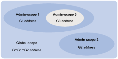
As shown in Figure 12, the admin-scoped zones 1 and 2 have no intersection, but the admin-scoped zone 3 is a subset of the admin-scoped zone 1. The global-scoped zone provides services for all the multicast groups that are not covered by the admin-scoped zones 1 and 2, G−G1−G2 in this case.
PIM-SSM
The ASM model includes PIM-DM and PIM-SM. The SSM model can be implemented by leveraging part of the PIM-SM technique. It is also called "PIM-SSM."
The SSM model provides a solution for source-specific multicast. It maintains the relationship between hosts and routers through IGMPv3.
In actual applications, part of IGMPv3 and PIM-SM techniques are adopted to implement the SSM model. In the SSM model, because receivers have located a multicast source, no RP or RPT is required. Multicast sources do not register with the RP, and the MSDP is not needed for discovering multicast sources in other PIM domains.
Neighbor discovery
PIM-SSM uses the same neighbor discovery mechanism as PIM-SM. For more information, see "Neighbor discovery."
DR election
PIM-SSM uses the same DR election mechanism as PIM-SM. For more information, see "DR election."
SPT building
The decision to build an RPT for PIM-SM or an SPT for PIM-SSM depends on whether the multicast group that the receiver joins is in the SSM group range. The SSM group range reserved by IANA is 232.0.0.0/8.
Figure 13 SPT building in PIM-SSM
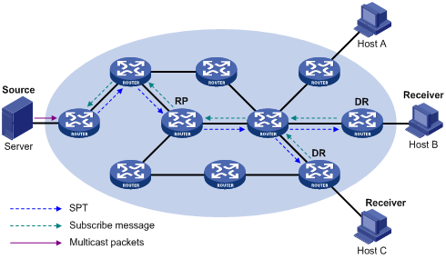
As shown in Figure 13, Host B and Host C are receivers. They send IGMPv3 report messages to their DRs to express their interest in the multicast information that the multicast source S sends to the multicast group G.
After receiving a report message, the DR first checks whether the group address in this message is in the SSM group range and does the following:
· If the group address is in the SSM group range, the DR sends a subscribe message hop by hop toward the multicast source S. All routers along the path from the DR to the source create an (S, G) entry to build an SPT. The SPT is rooted at the multicast source S and has the receivers as its leaves. This SPT is the transmission channel in PIM-SSM.
· If the group address is not in the SSM group range, the receiver-side DR sends a (*, G) join message to the RP. The multicast source registers with the source-side DR.
In PIM-SSM, the term "subscribe message" refers to a join message.
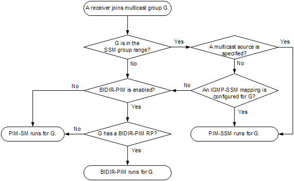
Relationship among PIM protocols
In a PIM network, PIM-DM cannot run together with PIM-SM, BIDIR-PIM, or PIM-SSM. However, PIM-SM, BIDIR-PIM, and PIM-SSM can run together. Figure 14 shows how the device selects one protocol from among them for a receiver trying to join a group.
For more information about IGMP SSM mapping, see "Configuring IGMP."
Figure 14 Relationship among PIM protocols
PIM support for VPNs
To support PIM for VPNs, a multicast router that runs PIM maintains an independent set of PIM neighbor table, multicast routing table, BSR information, and RP-set information for each VPN.
After receiving a multicast data packet, the multicast router checks which VPN the data packet belongs to. Then, the router forwards the packet according to the multicast routing table for that VPN or creates a multicast routing entry for that VPN.
Protocols and standards
· RFC 3973, Protocol Independent Multicast-Dense Mode (PIM-DM): Protocol Specification(Revised)
· RFC 4601, Protocol Independent Multicast-Sparse Mode (PIM-SM): Protocol Specification (Revised)
· RFC 4610, Anycast-RP Using Protocol Independent Multicast (PIM)
· RFC 5015, Bidirectional Protocol Independent Multicast (BIDIR-PIM)
· RFC 5059, Bootstrap Router (BSR) Mechanism for Protocol Independent Multicast (PIM)
· RFC 4607, Source-Specific Multicast for IP
· Draft-ietf-ssm-overview-05, An Overview of Source-Specific Multicast (SSM)
Configuring PIM
Configuration restrictions and guidelines
All the interfaces on a device must operate in the same PIM mode on the public network or the same VPN instance.
To avoid PIM routing table exceptions, do not use the same RP to provide services for PIM-SM and BIDIR-PIM when both of them run on the PIM network.
Configuring PIM-DM
This section describes how to configure PIM-DM.
PIM-DM configuration task list
|
Tasks at a glance |
|
(Required.) Enabling PIM-DM |
|
(Optional.) Enabling the state refresh feature |
|
(Optional.) Configuring state refresh parameters |
|
(Optional.) Configuring PIM-DM graft retry timer |
|
(Optional.) Configuring common PIM features |
Configuration prerequisites
Before you configure PIM-DM, configure a unicast routing protocol so that all devices in the domain can interoperate at the network layer.
Enabling PIM-DM
Enable IP multicast routing before you configure PIM.
With PIM-DM enabled on interfaces, routers can establish PIM neighbor relationship and process PIM messages from their PIM neighbors. As a best practice, enable PIM-DM on all non-border interfaces of the routers when you deploy a PIM-DM domain.
|
|
IMPORTANT: All the interfaces on a device must operate in the same PIM mode in the public network or the same VPN instance. |
To enable PIM-DM:
|
Step |
Command |
Remarks |
|
1. Enter system view. |
system-view |
N/A |
|
2. Enable IP multicast routing and enter MRIB view. |
multicast routing [ vpn-instance vpn-instance-name ] |
By default, IP multicast routing is disabled. |
|
3. Return to system view. |
quit |
N/A |
|
4. Enter interface view. |
interface interface-type interface-number |
N/A |
|
5. Enable PIM-DM. |
pim dm |
By default, PIM-DM is disabled. |
Enabling the state refresh feature
In a PIM-DM domain, this feature enables the PIM router that is directly connected to the source to periodically send state refresh messages. It also enables other PIM routers to refresh pruned state timers after receiving the state refresh messages. It prevents the pruned interfaces from resuming multicast forwarding. You must enable this feature on all PIM routers on a subnet.
To enable the state refresh feature:
|
Step |
Command |
Remarks |
|
1. Enter system view. |
system-view |
N/A |
|
2. Enter interface view. |
interface interface-type interface-number |
N/A |
|
3. Enable the state refresh feature. |
pim state-refresh-capable |
By default, the state refresh feature is enabled. |
Configuring state refresh parameters
The state refresh interval determines the interval at which a router sends state refresh messages. It is configurable.
A router might receive duplicate state refresh messages within a short time. To prevent this situation, you can configure the time that the router must wait to accept a new state refresh message. If the router receives a new state refresh message before the timer expires, it discards the message. If the router receives a new state refresh message after the timer expires, it accepts the message, refreshes its own PIM-DM state, and resets the waiting timer.
The TTL value of a state refresh message decrements by 1 whenever it passes a router before it is forwarded to the downstream node. The state refresh message stops being forwarded when the TTL value comes down to 0. A state refresh message with a large TTL value might cycle on a small network. To effectively control the propagation scope of state refresh messages, configure an appropriate TTL value based on the network size on the router directly connected with the multicast source.
To configure state refresh parameters:
|
Step |
Command |
Remarks |
|
1. Enter system view. |
system-view |
N/A |
|
2. Enter PIM view. |
pim [ vpn-instance vpn-instance-name ] |
N/A |
|
3. Configure the state refresh interval. |
state-refresh-interval interval |
The default setting is 60 seconds. |
|
4. Configure the amount of time to wait before accepting a new state refresh message. |
state-refresh-rate-limit time |
The default setting is 30 seconds. |
|
5. Configure the TTL value of state refresh messages. |
state-refresh-ttl ttl-value |
The default setting 255. |
Configuring PIM-DM graft retry timer
To configure the graft retry timer:
|
Step |
Command |
Remarks |
|
1. Enter system view. |
system-view |
N/A |
|
2. Enter interface view. |
interface interface-type interface-number |
N/A |
|
3. Configure the graft retry timer. |
pim timer graft-retry interval |
The default setting is 3 seconds. |
For more information about the configuration of other timers in PIM-DM, see "Configuring common PIM timers."
Configuring PIM-SM
This section describes how to configure PIM-SM.
PIM-SM configuration task list
|
Tasks at a glance |
Remarks |
|
(Required.) Enabling PIM-SM |
N/A |
|
(Required.) Configuring an RP: · (Optional.) Enabling Auto-RP listening · (Optional.) Configuring Anycast RP |
You must configure a static RP, a C-RP, or both in a PIM-SM domain. |
|
· (Required.) Configuring a C-BSR · (Optional.) Configuring a PIM domain border · (Optional.) Disabling BSM semantic fragmentation · (Optional.) Disabling the device from forwarding BSMs out of their incoming interfaces |
Skip the task of configuring a BSR on a network without C-RPs. |
|
(Optional.) Configuring multicast source registration |
N/A |
|
(Optional.) Configuring the switchover to SPT |
N/A |
|
(Optional.) Configuring common PIM features |
N/A |
Configuration prerequisites
Before you configure PIM-SM, configure a unicast routing protocol so that all devices in the domain can interoperate at the network layer.
Enabling PIM-SM
Enable IP multicast routing before you configure PIM.
With PIM-SM enabled on interfaces, routers can establish PIM neighbor relationship and process PIM messages from their PIM neighbors. As a best practice, enable PIM-SM on all non-border interfaces of routers when you deploy a PIM-SM domain.
|
|
IMPORTANT: All the interfaces on the same router must operate in the same PIM mode in the public network or the same VPN instance. |
To enable PIM-SM:
|
Step |
Command |
Remarks |
|
1. Enter system view. |
system-view |
N/A |
|
2. Enable IP multicast routing and enter MRIB view. |
multicast routing [ vpn-instance vpn-instance-name ] |
By default, IP multicast routing is disabled. |
|
3. Return to system view. |
quit |
N/A |
|
4. Enter interface view. |
interface interface-type interface-number |
N/A |
|
5. Enable PIM-SM. |
pim sm |
By default, PIM-SM is disabled. |
Configuring an RP
An RP can provide services for multiple or all multicast groups. However, only one RP can forward multicast traffic for a multicast group at a time.
An RP can be manually configured or dynamically elected through the BSR mechanism. For a large-scaled PIM network, configuring static RPs is a tedious job. Generally, static RPs are backups for dynamic RPs to enhance the robustness and operational manageability on a multicast network.
Configuring a static RP
If only one dynamic RP exists on a network, you can configure a static RP to avoid communication interruption caused by single-point failures. The static RP can also avoid waste of bandwidth due to frequent message exchange between C-RPs and the BSR. You must configure the same static RP on all routers in the PIM-SM domain.
When both a static RP and a dynamically elected RP exist on the network, you can specify the preferred keyword in the static-rp command to give priority to the static RP. The dynamic RP is used only when the static RP fails. If you do not specify the preferred keyword, the dynamic RP takes priority and the static RP is used only when the dynamic RP fails.
To configure a static RP:
|
Step |
Command |
Remarks |
|
1. Enter system view. |
system-view |
N/A |
|
2. Enter PIM view. |
pim [ vpn-instance vpn-instance-name ] |
N/A |
|
3. Configure a static RP for PIM-SM. |
static-rp rp-address [ ipv4-acl-number | preferred ] * |
By default, no static RPs exist. |
Configuring a C-RP
|
|
IMPORTANT: When you configure a C-RP, reserve a relatively large bandwidth between the C-RP and other devices in the PIM-SM domain. |
In a PIM-SM domain, if you want a router to become the RP, you can configure the router as a C-RP. As a best practice, configure C-RPs on backbone routers.
The C-RPs periodically send advertisement messages to the BSR, which collects RP-set information for RP election. You can configure the interval for sending the advertisement messages.
The holdtime option in C-RP advertisement messages defines the C-RP lifetime for the advertising C-RP. The BSR starts a holdtime timer for a C-RP after it receives an advertisement message. If the BSR does not receive any advertisement message when the timer expires, it considers the C-RP failed or unreachable.
A C-RP policy enables the BSR to filter C-RP advertisement messages by using an ACL that specifies the packet source address range and multicast groups. It is used to guard against C-RP spoofing. You must configure the same C-RP policy on all C-BSRs in the PIM-SM domain.
To configure a C-RP:
|
Step |
Command |
Remarks |
|
1. Enter system view. |
system-view |
N/A |
|
2. Enter PIM view. |
pim [ vpn-instance vpn-instance-name ] |
N/A |
|
3. Configure a C-RP. |
c-rp ip-address [ advertisement-interval adv-interval | group-policy ipv4-acl-number | holdtime hold-time | priority priority ] * |
By default, no C-RPs exist. |
|
4. (Optional.) Configure a C-RP policy. |
crp-policy ipv4-acl-number |
By default, no C-RP policy exists, and all C-RP advertisement messages are regarded as legal. |
Enabling Auto-RP listening
This feature enables the device to receive Auto-RP announcement and discovery messages and learn RP information. The destination IP addresses for Auto-RP announcement and discovery messages are 224.0.1.39 and 224.0.1.40, respectively.
To enable Auto-RP listening:
|
Step |
Command |
Remarks |
|
1. Enter system view. |
system-view |
N/A |
|
2. Enter PIM view. |
pim [ vpn-instance vpn-instance-name ] |
N/A |
|
3. Enable Auto-RP listening. |
auto-rp enable |
By default, Auto-RP listening is disabled. |
Configuring Anycast RP
|
|
IMPORTANT: The Anycast RP address must be different from the BSR address. Otherwise, the other Anycast RP member devices will discard the BSM sent by the BSR. |
You must configure a static RP or C-RPs in the PIM-SM domain before you configure the Anycast RP. Use the address of the static RP or the dynamically elected RP as the Anycast RP address.
When you configure Anycast RP, follow these restrictions and guidelines:
· You must add the device that the Anycast RP resides as an RP member to the Anycast RP set. The RP member address cannot be the same as the Anycast RP address.
· You must add all RP member addresses (including the local RP member address) to the Anycast RP set on each RP member device.
· As a best practice, configure no more than 16 Anycast RP members for an Anycast RP set.
· As a best practice, configure the loopback interface address of an RP member device as the RP member address. If you add multiple interface addresses of an RP member device to an Anycast RP set, the lowest IP address becomes the RP member address. The rest of the interface addresses become backup RP member addresses.
To configure Anycast RP:
|
Step |
Command |
Remarks |
|
1. Enter system view. |
system-view |
N/A |
|
2. Enter PIM view. |
pim [ vpn-instance vpn-instance-name ] |
N/A |
|
3. Configure Anycast RP. |
anycast-rp anycast-rp-address member-rp-address |
By default, Anycast RP is not configured. You can repeat this command to add multiple RP member addresses to the Anycast RP set. |
Configuring a BSR
You must configure a BSR if C-RPs are configured to dynamically select the RP. You do not need to configure a BSR when you have configured only a static RP but no C-RPs.
A PIM-SM domain can have only one BSR, but must have a minimum of one C-BSR. Any router can be configured as a C-BSR. Elected from C-BSRs, the BSR is responsible for collecting and advertising RP information in the PIM-SM domain.
Configuring a C-BSR
The BSR election process is summarized as follows:
1. Initially, each C-BSR regards itself as the BSR of the PIM-SM domain and sends a BSM to other routers in the domain.
2. When a C-BSR receives the BSM from another C-BSR, it compares its own priority with the priority carried in the message. The C-BSR with a higher priority wins the BSR election. If a tie exists in the priority, the C-BSR with a higher IP address wins. The loser uses the winner's BSR address to replace its own BSR address and no longer regards itself as the BSR. The winner retains its own BSR address and continues to regard itself as the BSR.
The elected BSR distributes the RP-set information collected from C-RPs to all routers in the PIM-SM domain. All routers use the same hash algorithm to select an RP for a specific multicast group.
A BSR policy enables a PIM-SM router to filter BSR messages by using an ACL that specifies the legal BSR addresses. It is used to guard against the following BSR spoofing cases:
· Some maliciously configured hosts can forge BSMs to fool routers and change RP mappings. Such attacks often occur on border routers.
· When an attacker controls a router on the network, the attacker can configure the router as a C-BSR to win the BSR election. Through this router, the attacker controls the advertising of RP information.
When you configure a C-BSR, follow these restrictions and guidelines:
· Configure C-BSRs on routers that are on the backbone network.
· Reserve a relatively large bandwidth between the C-BSR and the other devices in the PIM-SM domain.
· You must configure the same BSR policy on all routers in the PIM-SM domain. The BSR policy discards illegal BSR messages, but it partially guards against BSR attacks on the network. If an attacker controls a legal BSR, the problem still exists.
· When C-BSRs connect to other PIM routers through tunnels, static multicast routes must be configured to make sure the next hop to a C-BSR is a tunnel interface. Otherwise, RPF check is affected. For more information about static multicast routes, see "Configuring multicast routing and forwarding."
To configure a C-BSR:
|
Step |
Command |
Remarks |
|
1. Enter system view. |
system-view |
N/A |
|
2. Enter PIM view. |
pim [ vpn-instance vpn-instance-name ] |
N/A |
|
3. Configure a C-BSR. |
c-bsr ip-address [ scope group-address { mask-length | mask } ] [ hash-length hash-length | priority priority ] * |
By default, no C-BSRs exist. |
|
4. (Optional.) Configure a BSR policy. |
bsr-policy ipv4-acl-number |
By default, no BSR policy exists, and all bootstrap messages are regarded as legal. |
Configuring a PIM domain border
A PIM domain border determines the transmission boundary of bootstrap messages. Bootstrap messages cannot cross the domain border in either direction. A number of PIM domain border interfaces partition a network into different PIM-SM domains.
To configure a PIM domain border:
|
Step |
Command |
Remarks |
|
1. Enter system view. |
system-view |
N/A |
|
2. Enter interface view. |
interface interface-type interface-number |
N/A |
|
3. Configure a PIM domain border. |
pim bsr-boundary |
By default, an interface is not a PIM domain border. |
Disabling BSM semantic fragmentation
BSM semantic fragmentation enables a BSR to split a BSM into multiple BSM fragments (BSMFs) if the BSM exceeds the MTU. In this way, a non-BSR router can update the RP-set information for a group range after receiving all BSMFs for the range. The loss of one BSMF only affects the RP-set information of the group ranges that the fragment contains.
If the PIM-SM domain contains a device that does not support this feature, you must disable this feature on all C-BSRs. If you do not disable this feature, such a device regards a BSMF as a BSM and updates the RP-set information each time it receives a BSMF. It learns only part of the RP-set information, which further affects the RP election.
To disable BSM semantic fragmentation:
|
Step |
Command |
Remarks |
|
1. Enter system view. |
system-view |
N/A |
|
2. Enter PIM view. |
pim [ vpn-instance vpn-instance-name ] |
N/A |
|
3. Disable BSM semantic fragmentation. |
undo bsm-fragment enable |
By default, BSM semantic fragmentation is enabled. |
|
|
NOTE: Generally, a BSR performs BSM semantic fragmentation according to the MTU of its BSR interface. For BSMs originated due to learning of a new PIM neighbor, semantic fragmentation is performed according to the MTU of the interface that sends the BSMs. |
Disabling the device from forwarding BSMs out of their incoming interfaces
By default, the device forwards BSMs out of their incoming interfaces to avoid the situation that some devices cannot receive the BSMs due to inconsistent routing information. This results in duplicated traffic. To reduce traffic, you can disable the device from forwarding BSMs out of their incoming interfaces if all the devices have consistent routing information.
To disable the device from forwarding BSMs out of their incoming interfaces:
|
Step |
Command |
Remarks |
|
1. Enter system view. |
system-view |
N/A |
|
2. Enter PIM view. |
pim [ vpn-instance vpn-instance-name ] |
N/A |
|
3. Disable the device from forwarding BSMs out of their incoming interfaces. |
undo bsm-reflection enable |
By default, the device forwards BSMs out of their incoming interfaces. |
Configuring multicast source registration
You can configure the device to calculate the checksum based on the entire register message to ensure information integrity of a register message in the transmission process. If a device that does not support this feature is present on the network, you can configure the device to calculate the checksum based on the register message header.
The RP sends a register-stop message to the source-side DR in either of the following conditions:
· The RP stops serving the receivers for a multicast group. The receivers do not receive multicast data addressed to the multicast group through the RP.
· The RP receives multicast data that travels along the SPT.
After receiving the register-stop message, the DR stops sending register messages encapsulated with multicast data and starts a register-stop timer. Before the register-stop timer expires, the DR sends a null register message (a register message without encapsulated multicast data) to the RP and starts a register probe timer. If the DR receives a register-stop message before the register probe timer expires, it resets its register-stop timer. Otherwise, the DR starts sending register messages with encapsulated data again.
The register-stop timer is set to a random value chosen uniformly from (0.5 × register_suppression_time minus register_probe_time) to (1.5 × register_suppression_time minus register_probe_time). The register_probe_time is fixed to 5 seconds.
On all C-RP routers, perform the following tasks:
· Configure a PIM register policy.
· Configure the routers to calculate the checksum based on the entire register messages or the register message header.
On all routers that might become the source-side DR, configure the register suppression time.
To configure multicast source registration:
|
Step |
Command |
Remarks |
|
1. Enter system view. |
system-view |
N/A |
|
2. Enter PIM view. |
pim [ vpn-instance vpn-instance-name ] |
N/A |
|
3. Configure a PIM register policy. |
register-policy ipv4-acl-number |
By default, no PIM register policy exists, and all PIM register messages are regarded as legal. |
|
4. Configure the device to calculate the checksum based on the entire register message. |
register-whole-checksum |
By default, the device calculates the checksum based on the header of a register message. |
|
5. Configure the register suppression time. |
register-suppression-timeout interval |
The default setting is 60 seconds. |
Configuring the switchover to SPT
|
Step |
Command |
Remarks |
|
1. Enter system view. |
system-view |
N/A |
|
2. Enter PIM view. |
pim [ vpn-instance vpn-instance-name ] |
N/A |
|
3. Configure the switchover to SPT. |
spt-switch-threshold { immediacy | infinity } [ group-policy ipv4-acl-number ] |
By default, the first multicast data packet triggers the RPT to SPT switchover. |
Configuring BIDIR-PIM
This section describes how to configure BIDIR-PIM.
Configuration restrictions and guidelines
When you configure BIDIR-PIM, follow these restrictions and guidelines:
· BIDIR-PIM does not support multicast forwarding over a GRE tunnel.
· BIDIR-PIM does not support the following interfaces. To ensure multicast forwarding for BIDIR-PIM, do not use these interfaces as multicast data forwarding interfaces.
¡ Layer 3 Ethernet interfaces.
¡ Layer 3 Ethernet subinterfaces.
¡ Layer 3 aggregate interfaces.
¡ Layer 3 aggregate subinterfaces.
For more information about Layer 3 Ethernet interfaces and Layer 3 Ethernet subinterfaces, see Interface Configuration Guide. For more information about Layer 3 aggregate interfaces and Layer 3 aggregate subinterfaces, see Layer 2—LAN Switching Configuration Guide.
BIDIR-PIM configuration task list
|
Tasks at a glance |
Remarks |
|
(Required.) Enabling BIDIR-PIM |
N/A |
|
(Required.) Configuring an RP: · (Optional.) Enabling Auto-RP listening · (Optional.) Setting the maximum number of BIDIR-PIM RPs |
You must configure a static RP, a C-RP, or both in a BIDIR-PIM domain. |
|
· (Required.) Configuring a C-BSR · (Optional.) Configuring a PIM domain border · (Optional.) Disabling BSM semantic fragmentation · (Optional.) Disabling the device from forwarding BSMs out of their incoming interfaces |
Skip the task of configuring a BSR on a network without C-RPs. |
|
(Optional.) Configuring common PIM features |
N/A |
Configuration prerequisites
Before you configure BIDIR-PIM, configure a unicast routing protocol so that all devices in the domain can interoperate at the network layer.
Enabling BIDIR-PIM
Because BIDIR-PIM is implemented on the basis of PIM-SM, you must enable PIM-SM before you enable BIDIR-PIM. As a best practice, enable PIM-SM on all non-border interfaces of routers when you deploy a BIDIR-PIM domain.
|
|
IMPORTANT: All interfaces on a device must be enabled with the same PIM mode. |
To enable BIDIR-PIM:
|
Step |
Command |
Remarks |
|
1. Enter system view. |
system-view |
N/A |
|
2. Enable IP multicast routing and enter MRIB view. |
multicast routing [ vpn-instance vpn-instance-name ] |
By default, IP multicast routing is disabled. |
|
3. Return to system view. |
quit |
N/A |
|
4. Enter interface view. |
interface interface-type interface-number |
N/A |
|
5. Enable PIM-SM. |
pim sm |
By default, PIM-SM is disabled. |
|
6. Return to system view. |
quit |
N/A |
|
7. Enter PIM view. |
pim [ vpn-instance vpn-instance-name ] |
N/A |
|
8. Enable BIDIR-PIM. |
bidir-pim enable |
By default, BIDIR-PIM is disabled. |
Configuring an RP
|
|
CAUTION: When both PIM-SM and BIDIR-PIM run on the PIM network, do not use the same RP to provide services for PIM-SM and BIDIR-PIM. Otherwise, exceptions might occur to the PIM routing table. |
An RP can provide services for multiple or all multicast groups. However, only one RP can forward multicast traffic for a multicast group at a time.
An RP can be manually configured or dynamically elected through the BSR mechanism. For a large-scaled PIM network, configuring static RPs is a tedious job. Generally, static RPs are backups for dynamic RPs to enhance the robustness and operational manageability on a multicast network.
Configuring a static RP
If only one dynamic RP exists on a network, you can configure a static RP to avoid communication interruption caused by single-point failures. The static RP also avoids bandwidth waste due to frequent message exchange between C-RPs and the BSR. The static RP configuration must be the same on all routers in the BIDIR-PIM domain.
In BIDIR-PIM, a static RP can be specified with an unassigned IP address. This address must be on the same subnet with the link on which the static RP is configured. For example, if the IP addresses of the interfaces at the two ends of a link are 10.1.1.1/24 and 10.1.1.2/24, you can assign 10.1.1.100/24 to the static RP. As a result, the link becomes an RPL.
When both a static RP and a dynamically elected RP exist on the network, you can specify the preferred keyword in the static-rp command to give priority to the static RP. The dynamic RP is used only when the static RP fails. If you do not specify the preferred keyword, the dynamic RP takes priority and the static RP is used only when the dynamic RP fails.
To configure a static RP:
|
Step |
Command |
Remarks |
|
1. Enter system view. |
system-view |
N/A |
|
2. Enter PIM view. |
pim [ vpn-instance vpn-instance-name ] |
N/A |
|
3. Configure a static RP for BIDIR-PIM. |
static-rp rp-address bidir [ ipv4-acl-number | preferred ] * |
By default, no static RPs exist. |
Configuring a C-RP
|
|
IMPORTANT: When you configure a C-RP, reserve a large bandwidth between the C-RP and other devices in the BIDIR-PIM domain. |
In a BIDIR-PIM domain, if you want a router to become the RP, you can configure the router as a C-RP. The BSR collects the C-RP information according to the received advertisement messages from C-RPs or the auto-RP announcements from other routers. Then, it organizes the C-RP information into the RP-set information, which is flooded throughout the entire network. Then, the other routers on the network can determine the RPs for different multicast group ranges based on the RP-set information. As a best practice, configure C-RPs on backbone routers.
To enable the BSR to distribute the RP-set information in the BIDIR-PIM domain, the C-RPs must periodically send advertisement messages to the BSR. The BSR learns the C-RP information, encapsulates the C-RP information and its own IP address in a BSM, and floods the BSM to all PIM routers in the domain.
An advertisement message contains a holdtime option, which defines the C-RP lifetime for the advertising C-RP. After the BSR receives an advertisement message from a C-RP, it starts a timer for the C-RP. If the BSR does not receive any advertisement message when the timer expires, it considers the C-RP failed or unreachable.
To configure a C-RP:
|
Step |
Command |
Remarks |
|
1. Enter system view. |
system-view |
N/A |
|
2. Enter PIM view. |
pim [ vpn-instance vpn-instance-name ] |
N/A |
|
3. Configure a C-RP to provide services for BIDIR-PIM. |
c-rp ip-address [ advertisement-interval adv-interval | group-policy ipv4-acl-number | holdtime hold-time | priority priority ] * bidir |
By default, no C-RPs exist. |
Enabling Auto-RP listening
This feature enables the device to receive Auto-RP announcement and discovery messages and learn RP information. The destination IP addresses for Auto-RP announcement and discovery messages are 224.0.1.39 and 224.0.1.40, respectively.
To enable Auto-RP listening:
|
Step |
Command |
Remarks |
|
1. Enter system view. |
system-view |
N/A |
|
2. Enter PIM view. |
pim [ vpn-instance vpn-instance-name ] |
N/A |
|
3. Enable Auto-RP listening. |
auto-rp enable |
By default, Auto-RP listening is disabled. |
Setting the maximum number of BIDIR-PIM RPs
In a BIDIR-PIM domain, one DF election per RP is implemented on all PIM-enabled interfaces. To avoid unnecessary DF elections, do not configure multiple RPs for BIDIR-PIM.
This configuration sets a limit on the number of BIDIR-PIM RPs. If the number of RPs exceeds the limit, excess RPs do not take effect and can be used only for DF election rather than multicast data forwarding. The system does not delete the excess RPs. They must be deleted manually.
To set the maximum number of BIDIR-PIM RPs:
|
Step |
Command |
Remarks |
|
1. Enter system view. |
system-view |
N/A |
|
2. Enter PIM view. |
pim [ vpn-instance vpn-instance-name ] |
N/A |
|
3. Set the maximum number of BIDIR-PIM RPs. |
bidir-rp-limit limit |
The maximum number of BIDIR-PIM RPs is 6. |
Configuring a BSR
You must configure a BSR if C-RPs are configured to dynamically select the RP. You do not need to configure a BSR when you have configured only a static RP but no C-RPs.
A BIDIR-PIM domain can have only one BSR, but must have a minimum of one C-BSR. Any router can be configured as a C-BSR. Elected from C-BSRs, the BSR is responsible for collecting and advertising RP information in the BIDIR-PIM domain.
Configuring a C-BSR
|
|
IMPORTANT: Because the BSR and other devices exchange a large amount of information in the BIDIR-PIM domain, reserve a large bandwidth between the C-BSR and other devices. |
The BSR election process is summarized as follows:
1. Initially, each C-BSR regards itself as the BSR of the BIDIR-PIM domain and sends BSMs to other routers in the domain.
2. When a C-BSR receives the BSM from another C-BSR, it compares its own priority with the priority carried in the message. The C-BSR with a higher priority wins the BSR election. If a tie exists in the priority, the C-BSR with a higher IP address wins. The loser uses the winner's BSR address to replace its own BSR address and no longer regards itself as the BSR. The winner retains its own BSR address and continues to regard itself as the BSR.
The elected BSR distributes the RP-set information collected from C-RPs to all routers in the BIDIR-PIM domain. All routers use the same hash algorithm to select an RP for a specific multicast group.
A BSR policy enables the router to filter BSR messages by using an ACL that specifies the legal BSR addresses. It is used to guard against the following BSR spoofing cases:
· Some maliciously configured hosts can forge BSMs to fool routers and change RP mappings. Such attacks often occur on border routers.
· When an attacker controls a router on the network, the attacker can configure the router as a C-BSR to win the BSR election. Through this router, the attacker controls the advertising of RP information.
When you configure a C-BSR, follow these restrictions and guidelines:
· C-BSRs should be configured on routers on the backbone network.
· You must configure the same BSR policy on all routers in the BIDIR-PIM domain. The BSR policy discards illegal BSR messages, but it partially guards against BSR attacks on the network. If an attacker controls a legal BSR, the problem still exists.
· For C-BSRs interconnected through a GRE tunnel, configure static multicast routes to make sure the next hop to a C-BSR is a tunnel interface. For more information about static multicast routes, see "Configuring multicast routing and forwarding."
To configure a C-BSR:
|
Step |
Command |
Remarks |
|
1. Enter system view. |
system-view |
N/A |
|
2. Enter PIM view. |
pim [ vpn-instance vpn-instance-name ] |
N/A |
|
3. Configure a C-BSR. |
c-bsr ip-address [ scope group-address { mask-length | mask } ] [ hash-length hash-length | priority priority ] * |
By default, no C-BSRs exist. |
|
4. (Optional.) Configure a BSR policy. |
bsr-policy ipv4-acl-number |
By default, no BSR policy exists, and all bootstrap messages are regarded as legal. |
Configuring a PIM domain border
A PIM domain border determines the transmission boundary of bootstrap messages. Bootstrap messages cannot cross the domain border in either direction. A number of PIM domain border interfaces partition a network into different BIDIR-PIM domains.
To configure a PIM domain border:
|
Step |
Command |
Remarks |
|
1. Enter system view. |
system-view |
N/A |
|
2. Enter interface view. |
interface interface-type interface-number |
N/A |
|
3. Configure a PIM domain border. |
pim bsr-boundary |
By default, an interface is not a PIM domain border. |
Disabling BSM semantic fragmentation
BSM semantic fragmentation enables a BSR to split a BSM into multiple BSM fragments (BSMFs) if the BSM exceeds the MTU. In this way, a non-BSR router can update the RP-set information for a group range after receiving all BSMFs for the group range. The loss of one BSMF only affects the RP-set information of the group ranges that the fragment contains.
If the BIDIR-SM domain contains a device that does not support this feature, you must disable this feature on all C-BSRs. If you do not disable this feature, such a device regards a BSMF as a BSM and updates the RP-set information each time it receives a BSMF. It learns only part of the RP-set information, which further affects the RP election.
To disable BSM semantic fragmentation:
|
Step |
Command |
Remarks |
|
1. Enter system view. |
system-view |
N/A |
|
2. Enter PIM view. |
pim [ vpn-instance vpn-instance-name ] |
N/A |
|
3. Disable BSM semantic fragmentation. |
undo bsm-fragment enable |
By default, BSM semantic fragmentation is enabled. |
|
|
NOTE: Generally, a BSR performs BSM semantic fragmentation according to the MTU of its BSR interface. For BSMs originated due to learning of a new PIM neighbor, semantic fragmentation is performed according to the MTU of the interface that sends the BSMs. |
Disabling the device from forwarding BSMs out of their incoming interfaces
By default, the device forwards BSMs out of their incoming interfaces to avoid the situation that some devices cannot receive the BSMs due to inconsistent routing information. This results in duplicated traffic. To reduce traffic, you can disable the device from forwarding BSMs out of their incoming interfaces if all the devices have consistent routing information.
To disable the device from forwarding BSMs out of their incoming interfaces:
|
Step |
Command |
Remarks |
|
1. Enter system view. |
system-view |
N/A |
|
2. Enter PIM view. |
pim [ vpn-instance vpn-instance-name ] |
N/A |
|
3. Disable the device from forwarding BSMs out of their incoming interfaces. |
undo bsm-reflection enable |
By default, the device forwards BSMs out of their incoming interfaces. |
Configuring PIM-SSM
PIM-SSM requires IGMPv3 support. Enable IGMPv3 on PIM routers that connect to multicast receivers.
PIM-SSM configuration task list
|
Tasks at a glance |
|
(Required.) Enabling PIM-SM |
|
(Optional.) Configuring the SSM group range |
|
(Optional.) Configuring common PIM features |
Configuration prerequisites
Before you configure PIM-SSM, configure a unicast routing protocol so that all devices in the domain can interoperate at the network layer.
Enabling PIM-SM
Before you configure PIM-SSM, you must enable PIM-SM, because the implementation of the SSM model is based on subsets of PIM-SM.
When you deploy a PIM-SSM domain, enable PIM-SM on non-border interfaces of the routers.
|
|
IMPORTANT: All the interfaces on a device must be enabled with the same PIM mode. |
To enable PIM-SM:
|
Step |
Command |
Remarks |
|
1. Enter system view. |
system-view |
N/A |
|
2. Enable IP multicast routing, and enter MRIB view. |
multicast routing [ vpn-instance vpn-instance-name ] |
By default, IP multicast routing is disabled. |
|
3. Return to system view. |
quit |
N/A |
|
4. Enter interface view. |
interface interface-type interface-number |
N/A |
|
5. Enable PIM-SM. |
pim sm |
By default, PIM-SM is disabled. |
Configuring the SSM group range
When a PIM-SM enabled interface receives a multicast packet, it checks whether the multicast group address of the packet is in the SSM group range. If the multicast group address is in this range, the PIM mode for this packet is PIM-SSM. If the multicast group address is not in this range, the PIM mode is PIM-SM.
Configuration restrictions and guidelines
When you configure the SSM group range, follow these restrictions and guidelines:
· Configure the same SSM group range on all routers in the entire PIM-SSM domain. Otherwise, multicast information cannot be delivered through the SSM model.
· When a member of a multicast group in the SSM group range sends an IGMPv1 or IGMPv2 report message, the device does not trigger a (*, G) join.
Configuration procedure
To configure an SSM group range:
|
Step |
Command |
Remarks |
|
1. Enter system view. |
system-view |
N/A |
|
2. Enter PIM view. |
pim |
N/A |
|
3. Configure the SSM group range. |
ssm-policy ipv4-acl-number |
By default, the SSM group range is 232.0.0.0/8. |
Configuring common PIM features
Common PIM feature configuration task list
|
Tasks at a glance |
|
(Optional.) Configuring a multicast source policy |
|
(Optional.) Configuring a PIM hello policy |
|
(Optional.) Configuring PIM hello message options |
|
(Optional.) Configuring common PIM timers |
|
(Optional.) Setting the maximum size of a join or prune message |
|
(Optional.) Enabling BFD for PIM |
|
(Optional.) Enabling PIM passive mode |
|
(Optional.) Enabling PIM NSR |
|
(Optional.) Enabling SNMP notifications for PIM |
|
(Optional.) Setting a DSCP value for outgoing PIM messages |
Configuration prerequisites
Before you configure common PIM features, complete the following tasks:
· Configure a unicast routing protocol so that all devices in the domain can interoperate at the network layer.
· Configure PIM-DM or PIM-SM.
Configuring a multicast source policy
This feature enables the device to filter multicast data by using an ACL that specifies the multicast sources and the optional groups. It filters not only data packets but also register messages with multicast data encapsulated. It controls the information available to downstream receivers.
To configure a multicast source policy:
|
Step |
Command |
Remarks |
|
1. Enter system view. |
system-view |
N/A |
|
2. Enter PIM view. |
pim [ vpn-instance vpn-instance-name ] |
N/A |
|
3. Configure a multicast source policy. |
source-policy ipv4-acl-number |
By default, no multicast source policy exists. The device does not filter multicast data packets. |
Configuring a PIM hello policy
This feature enables the device to filter PIM hello messages by using an ACL that specifies the packet source addresses. It is used to guard against PIM message attacks and to establish correct PIM neighboring relationships.
If hello messages of an existing PIM neighbor are filtered out by the policy, the neighbor is automatically removed when its aging timer expires.
To configure a PIM hello policy:
|
Step |
Command |
Remarks |
|
1. Enter system view. |
system-view |
N/A |
|
2. Enter interface view. |
interface interface-type interface-number |
N/A |
|
3. Configure a PIM hello policy. |
pim neighbor-policy ipv4-acl-number |
By default, no PIM hello policy exists on an interface, and all PIM hello messages are regarded as legal. |
Configuring PIM hello message options
In either a PIM-DM domain or a PIM-SM domain, hello messages exchanged among routers contain the following configurable options:
· DR_Priority (for PIM-SM only)—Priority for DR election. The device with the highest priority wins the DR election. You can configure this option for all the routers in a shared-media LAN that directly connects to the multicast source or the receivers.
· Holdtime—PIM neighbor lifetime. If a router does not receive a hello message from a neighbor when the neighbor lifetime expires, it regards the neighbor failed or unreachable.
· LAN_Prune_Delay—Delay of pruning a downstream interface on a shared-media LAN. This option has LAN delay, override interval, and neighbor tracking support (the capability to disable join message suppression).
The LAN delay defines the PIM message propagation delay. The override interval defines a period for a router to override a prune message. If the propagation delay or override interval on different PIM routers on a shared-media LAN are different, the largest ones apply.
On the shared-media LAN, the propagation delay and override interval are used as follows:
¡ If a router receives a prune message on its upstream interface, it means that there are downstream routers on the shared-media LAN. If this router still needs to receive multicast data, it must send a join message to override the prune message within the override interval.
¡ When a router receives a prune message from its downstream interface, it does not immediately prune this interface. Instead, it starts a timer (the propagation delay plus the override interval). If interface receives a join message before the timer expires, the router does not prune the interface. Otherwise, the router prunes the interface.
If you enable neighbor tracking on an upstream router, this router can track the states of the downstream nodes for which the joined state holdtime timer has not expired. If you want to enable neighbor tracking, you must enable it on all PIM routers on a shared-media LAN. Otherwise, the upstream router cannot track join messages from every downstream routers.
· Generation ID—A router generates a generation ID for hello messages when an interface is enabled with PIM. The generation ID is a random value, but only changes when the status of the router changes. If a PIM router finds that the generation ID in a hello message from the upstream router has changed, it assumes that the status of the upstream router has changed. In this case, it sends a join message to the upstream router for status update. You can configure an interface to drop hello messages without the generation ID options to promptly know the status of an upstream router.
You can configure hello message options for all interfaces in PIM view or for the current interface in interface view. The configuration made in interface view takes priority over the configuration made in PIM view.
Configuring hello message options globally
|
Step |
Command |
Remarks |
|
1. Enter system view. |
system-view |
N/A |
|
2. Enter PIM view. |
pim [ vpn-instance vpn-instance-name ] |
N/A |
|
3. Set the DR priority. |
hello-option dr-priority priority |
The default setting is 1. |
|
4. Set the neighbor lifetime. |
hello-option holdtime time |
The default setting is 105 seconds. |
|
5. Set the PIM message propagation delay for a shared-media LAN. |
hello-option lan-delay delay |
The default setting is 500 milliseconds. |
|
6. Set the override interval. |
hello-option override-interval interval |
The default setting is 2500 milliseconds. |
|
7. Enable neighbor tracking. |
hello-option neighbor-tracking |
By default, neighbor tracking is disabled. |
Configuring hello message options on an interface
|
Step |
Command |
Remarks |
|
1. Enter system view. |
system-view |
N/A |
|
2. Enter interface view. |
interface interface-type interface-number |
N/A |
|
3. Set the DR priority. |
pim hello-option dr-priority priority |
The default setting is 1. |
|
4. Set the neighbor lifetime. |
pim hello-option holdtime time |
The default setting is 105 seconds. |
|
5. Set the PIM message propagation delay. |
pim hello-option lan-delay delay |
The default setting is 500 milliseconds. |
|
6. Set the override interval. |
pim hello-option override-interval interval |
The default setting is 2500 milliseconds. |
|
7. Enable neighbor tracking. |
pim hello-option neighbor-tracking |
By default, neighbor tracking is disabled. |
|
8. Enable dropping hello messages without the Generation ID option. |
pim require-genid |
By default, an interface accepts hello messages without the Generation ID option. |
Configuring common PIM timers
|
|
IMPORTANT: To prevent the upstream neighbors from aging out, you must configure the interval for sending join/prune messages to be less than the joined/pruned state holdtime timer. |
The following are common timers in PIM:
· Hello interval—Interval at which a PIM router sends hello messages to discover PIM neighbors, and maintain PIM neighbor relationship.
· Triggered hello delay—Maximum delay for sending a hello message to avoid collisions caused by simultaneous hello messages. After receiving a hello message, a PIM router waits for a random time before sending a hello message. This random time is in the range of 0 to the triggered hello delay.
· Join/Prune interval—Interval at which a PIM router sends join/prune messages to its upstream routers for state update.
· Joined/Pruned state holdtime—Time for which a PIM router keeps the joined/pruned state for the downstream interfaces. This joined/pruned state holdtime is specified in a join/prune message.
· Multicast source lifetime—Lifetime that a PIM router maintains for a multicast source. If a router does not receive subsequent multicast data from the multicast source S when the timer expires, it deletes the (S, G) entry for the multicast source.
You can configure common PIM timers for all interfaces in PIM view or for the current interface in interface view. The configuration made in interface view takes priority over the configuration made in PIM view.
|
|
TIP: As a best practice, use the defaults for a network without special requirements. |
Configuring common PIM timers globally
|
Step |
Command |
Remarks |
|
1. Enter system view. |
system-view |
N/A |
|
2. Enter PIM view. |
pim [ vpn-instance vpn-instance-name ] |
N/A |
|
3. Set the hello interval. |
timer hello interval |
The default setting is 30 seconds. |
|
4. Set the join/prune interval. |
timer join-prune interval |
The default setting is 60 seconds. This configuration takes effect after the current interval ends. |
|
5. Set the joined/pruned state holdtime. |
holdtime join-prune time |
The default setting is 210 seconds. |
|
6. Set the multicast source lifetime. |
source-lifetime time |
The default setting is 210 seconds. |
Configuring common PIM timers on an interface
|
Step |
Command |
Remarks |
|
1. Enter system view. |
system-view |
N/A |
|
2. Enter interface view. |
interface interface-type interface-number |
N/A |
|
3. Set the hello interval. |
pim timer hello interval |
The default setting is 30 seconds. |
|
4. Set the triggered hello delay. |
pim triggered-hello-delay delay |
The default setting is 5 seconds. |
|
5. Set the join/prune interval. |
pim timer join-prune interval |
The default setting is 60 seconds. This configuration takes effect after the current interval ends. |
|
6. Set the joined/pruned state holdtime. |
pim holdtime join-prune time |
The default setting is 210 seconds. |
Setting the maximum size of a join or prune message
The loss of an oversized join or prune message might result in loss of massive information. You can set a small value for the size of a join or prune message to reduce the impact.
To set the maximum size of a join or prune message:
|
Step |
Command |
Remarks |
|
1. Enter system view. |
system-view |
N/A |
|
2. Enter PIM view. |
pim [ vpn-instance vpn-instance-name ] |
N/A |
|
3. Set the maximum size of a join or prune message. |
jp-pkt-size size |
The default setting is 1200 bytes. |
Enabling BFD for PIM
If a DR on a shared-media network fails, a new DR election process does not start until the DR ages out. In addition, it might take a long period of time before other routers detect the link failures and trigger a new DR election. To start a new DR election process immediately after the original DR fails, enable BFD for PIM to detect link failures among PIM neighbors.
You must enable BFD for PIM on all PIM routers on a shared-media network. For more information about BFD, see High Availability Configuration Guide.
You must enable PIM-DM or PIM-SM on an interface before you configure this feature on the interface.
To enable BFD for PIM:
|
Step |
Command |
Remarks |
|
1. Enter system view. |
system-view |
N/A |
|
2. Enter interface view. |
interface interface-type interface-number |
N/A |
|
3. Enable BFD for PIM. |
pim bfd enable |
By default, BFD is disabled for PIM. |
Enabling PIM passive mode
To guard against PIM hello spoofing, you can enable PIM passive mode on a receiver-side interface. The PIM passive interface cannot receive or forward PIM protocol messages (excluding register, register-stop and C-RP-Adv messages), and it acts as the DR on the subnet. In BIDIR-PIM, it also acts as the DF.
Configuration restrictions and guidelines
When you enable PIM passive mode, follow these restrictions and guidelines:
· This feature takes effect only when PIM-DM or PIM-SM is enabled on the interface.
· To avoid duplicate multicast data transmission and flow loop, do not enable this feature on a shared-media LAN with multiple PIM routers.
Configuration procedure
To enable PIM passive mode on an interface:
|
Step |
Command |
Remarks |
|
1. Enter system view. |
system-view |
N/A |
|
2. Enter interface view. |
interface interface-type interface-number |
N/A |
|
3. Enable PIM passive mode on the interface. |
pim passive |
By default, PIM passive mode is disabled on an interface. |
Enabling PIM NSR
This feature enables PIM to back up protocol state information and data, including PIM neighbor information and routes, from the active process to the standby process. The standby process immediately takes over when the active process fails. Use this feature to avoid route flapping and forwarding interruption for PIM when an active/standby switchover occurs.
To enable PIM NSR:
|
Step |
Command |
Remarks |
|
1. Enter system view. |
system-view |
N/A |
|
2. Enable PIM NSR. |
pim non-stop-routing |
By default, PIM NSR is disabled. |
Enabling SNMP notifications for PIM
To report critical PIM events to an NMS, enable SNMP notifications for PIM. For PIM event notifications to be sent correctly, you must also configure SNMP as described in Network Management and Monitoring Configuration Guide.
To enable SNMP notifications for PIM:
|
Step |
Command |
Remarks |
|
1. Enter system view. |
system-view |
N/A |
|
2. Enable SNMP notifications for PIM. |
snmp-agent trap enable pim [ candidate-bsr-win-election | elected-bsr-lost-election | neighbor-loss ] * |
By default, SNMP notifications for PIM are enabled. |
Setting a DSCP value for outgoing PIM messages
The DSCP value determines the packet transmission priority. A greater DSCP value represents a higher priority.
To set a DSCP value for outgoing PIM messages:
|
Step |
Command |
Remarks |
|
1. Enter system view. |
system-view |
N/A |
|
2. Enter PIM view. |
pim [ vpn-instance vpn-instance-name ] |
N/A |
|
3. Set a DSCP value for outgoing PIM messages. |
dscp dscp-value |
By default, the DSCP value is 48 in outgoing PIM messages. |
Displaying and maintaining PIM
Execute display commands in any view and reset commands in user view.
|
Task |
Command |
|
Display register-tunnel interface information. |
display interface [ register-tunnel [ interface-number ] ] [ brief [ description | down ] ] |
|
Display BSR information in the PIM-SM domain. |
display pim [ vpn-instance vpn-instance-name ] bsr-info |
|
Display information about the routes used by PIM. |
display pim [ vpn-instance vpn-instance-name ] claimed-route [ source-address ] |
|
Display C-RP information in the PIM-SM domain. |
display pim [ vpn-instance vpn-instance-name ] c-rp [ local ] |
|
Display DF information in the BIDIR-PIM domain. |
display pim [ vpn-instance vpn-instance-name ] df-info [ rp-address ] |
|
Display PIM information on an interface. |
display pim [ vpn-instance vpn-instance-name ] interface [ interface-type interface-number ] [ verbose ] |
|
Display PIM neighbor information. |
display pim [ vpn-instance vpn-instance-name ] neighbor [ neighbor-address | interface interface-type interface-number | verbose ] * |
|
Display PIM routing entries. |
display pim [ vpn-instance vpn-instance-name ] routing-table [ group-address [ mask { mask-length | mask } ] | source-address [ mask { mask-length | mask } ] | flags flag-value | fsm | incoming-interface interface-type interface-number | mode mode-type | outgoing-interface { exclude | include | match } interface-type interface-number | proxy ] * |
|
Display RP information in the PIM-SM domain. |
display pim [ vpn-instance vpn-instance-name ] rp-info [ group-address ] |
|
Display statistics for PIM packets. |
display pim statistics |
PIM configuration examples
PIM-DM configuration example
Network requirements
As shown in Figure 15:
· OSPF runs on the network.
· VOD streams are sent to receiver hosts in multicast. The receiver groups of different organizations form stub networks, and one or more receiver hosts exist on each stub network.
· The entire PIM domain operates in the dense mode.
· Host A and Host C are multicast receivers on two stub networks.
· IGMPv2 runs between Switch A and N1, and between Switch B, Switch C, and N2.
Table 1 Interface and IP address assignment
|
Device |
Interface |
IP address |
Device |
Interface |
IP address |
|
Switch A |
Vlan-int100 |
10.110.1.1/24 |
Switch C |
Vlan-int102 |
192.168.3.1/24 |
|
Switch A |
Vlan-int103 |
192.168.1.1/24 |
Switch D |
Vlan-int300 |
10.110.5.1/24 |
|
Switch B |
Vlan-int200 |
10.110.2.1/24 |
Switch D |
Vlan-int103 |
192.168.1.2/24 |
|
Switch B |
Vlan-int101 |
192.168.2.1/24 |
Switch D |
Vlan-int101 |
192.168.2.2/24 |
|
Switch C |
Vlan-int200 |
10.110.2.2/24 |
Switch D |
Vlan-int102 |
192.168.3.2/24 |
Configuration procedure
1. Assign an IP address and subnet mask for each interface, as shown in Figure 15. (Details not shown.)
2. Configure OSPF on the switches in the PIM-DM domain. (Details not shown.)
3. Enable IP multicast routing, IGMP, and PIM-DM:
# On Switch A, enable IP multicast routing.
<SwitchA> system-view
[SwitchA] multicast routing
[SwitchA-mrib] quit
# Enable IGMP on the receiver-side interface (VLAN-interface 100).
[SwitchA] interface vlan-interface 100
[SwitchA-Vlan-interface100] igmp enable
[SwitchA-Vlan-interface100] quit
# Enable PIM-DM on VLAN-interface 103.
[SwitchA] interface vlan-interface 103
[SwitchA-Vlan-interface103] pim dm
[SwitchA-Vlan-interface103] quit
# Enable IP multicast routing, IGMP, and PIM-DM on Switch B and Switch C in the same way Switch A is configured. (Details not shown.)
# On Switch D, enable IP multicast routing, and enable PIM-DM on each interface.
<SwitchD> system-view
[SwitchD] multicast routing
[SwitchD-mrib] quit
[SwitchD] interface vlan-interface 300
[SwitchD-Vlan-interface300] pim dm
[SwitchD-Vlan-interface300] quit
[SwitchD] interface vlan-interface 103
[SwitchD-Vlan-interface103] pim dm
[SwitchD-Vlan-interface103] quit
[SwitchD] interface vlan-interface 101
[SwitchD-Vlan-interface101] pim dm
[SwitchD-Vlan-interface101] quit
[SwitchD] interface vlan-interface 102
[SwitchD-Vlan-interface102] pim dm
[SwitchD-Vlan-interface102] quit
Verifying the configuration
# Display PIM information on Switch D.
[SwitchD] display pim interface
Interface NbrCnt HelloInt DR-Pri DR-Address
Vlan300 0 30 1 10.110.5.1 (local)
Vlan103 1 30 1 192.168.1.2 (local)
Vlan101 1 30 1 192.168.2.2 (local)
Vlan102 1 30 1 192.168.3.2 (local)
# Display PIM neighboring relationships on Switch D.
[SwitchD] display pim neighbor
Total Number of Neighbors = 3
Neighbor Interface Uptime Expires Dr-Priority Mode
192.168.1.1 Vlan103 00:02:22 00:01:27 1
192.168.2.1 Vlan101 00:00:22 00:01:29 3
192.168.3.1 Vlan102 00:00:23 00:01:31 5
# Send an IGMP report from Host A to join multicast group 225.1.1.1. (Details not shown.)
# Send multicast data from multicast source 10.110.5.100/24 to multicast group 225.1.1.1. (Details not shown.)
# Display PIM routing entries on Switch A.
[SwitchA] display pim routing-table
Total 1 (*, G) entry; 1 (S, G) entry
(*, 225.1.1.1)
Protocol: pim-dm, Flag: WC
UpTime: 00:04:25
Upstream interface: NULL
Upstream neighbor: NULL
RPF prime neighbor: NULL
Downstream interface(s) information:
Total number of downstreams: 1
1: Vlan-interface100
Protocol: igmp, UpTime: 00:04:25, Expires: -
(10.110.5.100, 225.1.1.1)
Protocol: pim-dm, Flag: ACT
UpTime: 00:06:14
Upstream interface: Vlan-interface103
Upstream neighbor: 192.168.1.2
RPF prime neighbor: 192.168.1.2
Downstream interface(s) information:
Total number of downstreams: 1
1: Vlan-interface100
Protocol: pim-dm, UpTime: 00:04:25, Expires: -
# Display PIM routing entries on Switch D.
[SwitchD] display pim routing-table
Total 0 (*, G) entry; 1 (S, G) entry
(10.110.5.100, 225.1.1.1)
Protocol: pim-dm, Flag: LOC ACT
UpTime: 00:03:27
Upstream interface: Vlan-interface300
Upstream neighbor: NULL
RPF prime neighbor: NULL
Downstream interface(s) information:
Total number of downstreams: 2
1: Vlan-interface103
Protocol: pim-dm, UpTime: 00:03:27, Expires: -
2: Vlan-interface102
Protocol: pim-dm, UpTime: 00:03:27, Expires: -
The output shows the following information:
· Switches on the SPT path (Switch A and Switch D) have the correct (S, G) entries.
· Switch A has the correct (*, G) entry.
PIM-SM non-scoped zone configuration example
Network requirements
As shown in Figure 16:
· OSPF runs on the network.
· VOD streams are sent to receiver hosts in multicast. The receivers of different subnets form stub networks, and a minimum of one receiver host exist on each stub network.
· The entire PIM-SM domain contains only one BSR.
· Host A and Host C are multicast receivers on two stub networks N1 and N2.
· Specify VLAN-interface 102 on Switch E as a C-BSR and a C-RP. The C-RP is designated to multicast group range 225.1.1.0/24. Specify VLAN-interface 101 of Switch D as the static RP on all the switches to back up the dynamic RP.
· IGMPv2 runs between Switch A and N1, and between Switch B, Switch C, and N2.

Table 2 Interface and IP address assignment
|
Device |
Interface |
IP address |
Device |
Interface |
IP address |
|
Switch A |
Vlan-int100 |
10.110.1.1/24 |
Switch D |
Vlan-int300 |
10.110.5.1/24 |
|
Switch A |
Vlan-int101 |
192.168.1.1/24 |
Switch D |
Vlan-int101 |
192.168.1.2/24 |
|
Switch A |
Vlan-int102 |
192.168.9.1/24 |
Switch D |
Vlan-int105 |
192.168.4.2/24 |
|
Switch B |
Vlan-int200 |
10.110.2.1/24 |
Switch E |
Vlan-int104 |
192.168.3.2/24 |
|
Switch B |
Vlan-int103 |
192.168.2.1/24 |
Switch E |
Vlan-int103 |
192.168.2.2/24 |
|
Switch C |
Vlan-int200 |
10.110.2.2/24 |
Switch E |
Vlan-int102 |
192.168.9.2/24 |
|
Switch C |
Vlan-int104 |
192.168.3.1/24 |
Switch E |
Vlan-int105 |
192.168.4.1/24 |
Configuration procedure
1. Assign an IP address and subnet mask to each interface, as shown in Figure 16. (Details not shown.)
2. Configure OSPF on all switches in the PIM-SM domain. (Details not shown.)
3. Enable IP multicast routing, and enable IGMP and PIM-SM:
# On Switch A, enable IP multicast routing.
<SwitchA> system-view
[SwitchA] multicast routing
[SwitchA-mrib] quit
# Enable IGMP on the receiver-side interface (VLAN-interface 100).
[SwitchA] interface vlan-interface 100
[SwitchA-Vlan-interface100] igmp enable
[SwitchA-Vlan-interface100] quit
# Enable PIM-SM on the other interfaces.
[SwitchA] interface vlan-interface 101
[SwitchA-Vlan-interface101] pim sm
[SwitchA-Vlan-interface101] quit
[SwitchA] interface vlan-interface 102
[SwitchA-Vlan-interface102] pim sm
[SwitchA-Vlan-interface102] quit
# Enable IP multicast routing, IGMP, and PIM-SM on Switch B and Switch C in the same way Switch A is configured. (Details not shown.)
# Enable IP multicast routing and PIM-SM on Switch D and Switch E in the same way Switch A is configured. (Details not shown.)
4. Configure C-BSRs, C-RPs, and the static RP:
# On Switch E, configure the service scope of RP advertisements.
<SwitchE> system-view
[SwitchE] acl basic 2005
[SwitchE-acl-ipv4-basic-2005] rule permit source 225.1.1.0 0.0.0.255
[SwitchE-acl-ipv4-basic-2005] quit
# Configure VLAN-interface 102 as a C-BSR and a C-RP.
[SwitchE] pim
[SwitchE-pim] c-bsr 192.168.9.2
[SwitchE-pim] c-rp 192.168.9.2 group-policy 2005
# Configure VLAN-interface 101 of Switch D as the static RP.
[SwitchE-pim] static-rp 192.168.1.2
[SwitchE-pim] quit
# On Switch A, configure VLAN-interface 101 of Switch D as the static RP.
[SwitchA] pim
[SwitchA-pim] static-rp 192.168.1.2
[SwitchA-pim] quit
# Configure the static RP on Switch B, Switch C, and Switch D in the same way Switch A is configured. (Details not shown.)
Verifying the configuration
# Display PIM information on Switch A.
[SwitchA] display pim interface
Interface NbrCnt HelloInt DR-Pri DR-Address
Vlan101 1 30 1 192.168.1.2
Vlan102 1 30 1 192.168.9.2
# Display BSR information on Switch A.
[SwitchA] display pim bsr-info
Scope: non-scoped
State: Accept Preferred
Bootstrap timer: 00:01:44
Elected BSR address: 192.168.9.2
Priority: 64
Hash mask length: 30
Uptime: 00:11:18
# Display BSR information on Switch E.
[SwitchE] display pim bsr-info
Scope: non-scoped
State: Elected
Bootstrap timer: 00:01:44
Elected BSR address: 192.168.9.2
Priority: 64
Hash mask length: 30
Uptime: 00:11:18
Candidate BSR address: 192.168.9.2
Priority: 64
Hash mask length: 30
# Display RP information on Switch A.
[SwitchA] display pim rp-info
BSR RP information:
Scope: non-scoped
Group/MaskLen: 225.1.1.0/24
RP address Priority HoldTime Uptime Expires
192.168.9.2 192 180 00:51:45 00:02:22
Static RP information:
RP address ACL Mode Preferred
192.168.1.2 ---- pim-sm No
PIM-SM admin-scoped zone configuration example
Network requirements
As shown in Figure 17:
· OSPF runs on the network.
· VOD streams are sent to receiver hosts in multicast. The entire PIM-SM domain is divided into admin-scoped zone 1, admin-scoped zone 2, and the global-scoped zone. Switch B, Switch C, and Switch D are ZBRs of the three zones, respectively.
· Source 1 and Source 2 send different multicast data to the multicast group 239.1.1.1. Host A receives the multicast data only from Source 1, and Host B receives the multicast data only from Source 2. Source 3 sends multicast data to multicast group 224.1.1.1. Host C is a multicast receiver for the multicast group 224.1.1.1.
· VLAN-interface 101 of Switch B acts as a C-BSR and a C-RP for admin-scoped zone 1, and VLAN-interface 105 of Switch D acts as a C-BSR and a C-RP for admin-scoped zone 2. Both of the two interfaces are designated to multicast group range 239.0.0.0/8. VLAN-interface 109 of Switch F acts as a C-BSR and a C-RP for the global-scoped zone, and is designated to all the multicast groups that are not in the range 239.0.0.0/8.
· IGMPv2 runs between Switch A, Switch E, Switch I, and the receivers that directly connect to them, respectively.
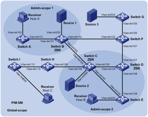
Table 3 Interface and IP address assignment
|
Device |
Interface |
IP address |
Device |
Interface |
IP address |
|
Switch A |
Vlan-int100 |
192.168.1.1/24 |
Switch D |
Vlan-int105 |
10.110.5.2/24 |
|
Switch A |
Vlan-int101 |
10.110.1.1/24 |
Switch D |
Vlan-int108 |
10.110.7.1/24 |
|
Switch B |
Vlan-int200 |
192.168.2.1/24 |
Switch D |
Vlan-int107 |
10.110.8.1/24 |
|
Switch B |
Vlan-int101 |
10.110.1.2/24 |
Switch E |
Vlan-int400 |
192.168.4.1/24 |
|
Switch B |
Vlan-int103 |
10.110.2.1/24 |
Switch E |
Vlan-int104 |
10.110.4.2/24 |
|
Switch B |
Vlan-int102 |
10.110.3.1/24 |
Switch E |
Vlan-int108 |
10.110.7.2/24 |
|
Switch C |
Vlan-int300 |
192.168.3.1/24 |
Switch F |
Vlan-int109 |
10.110.9.1/24 |
|
Switch C |
Vlan-int104 |
10.110.4.1/24 |
Switch F |
Vlan-int107 |
10.110.8.2/24 |
|
Switch C |
Vlan-int105 |
10.110.5.1/24 |
Switch F |
Vlan-int102 |
10.110.3.2/24 |
|
Switch C |
Vlan-int103 |
10.110.2.2/24 |
Switch G |
Vlan-int500 |
192.168.5.1/24 |
|
Switch C |
Vlan-int106 |
10.110.6.1/24 |
Switch G |
Vlan-int109 |
10.110.9.2/24 |
|
Switch H |
Vlan-int110 |
10.110.10.1/24 |
Source 1 |
— |
192.168.2.10/24 |
|
Switch H |
Vlan-int106 |
10.110.6.2/24 |
Source 2 |
— |
192.168.3.10/24 |
|
Switch I |
Vlan-int600 |
192.168.6.1/24 |
Source 3 |
— |
192.168.5.10/24 |
|
Switch I |
Vlan-int110 |
10.110.10.2/24 |
|
|
|
Configuration procedure
1. Assign an IP address and subnet mask to each interface, as shown in Figure 17. (Details not shown.)
2. Configure OSPF on all switches in the PIM-SM domain. (Details not shown.)
3. Enable IP multicast routing, and enable IGMP and PIM-SM:
# On Switch A, enable IP multicast routing.
<SwitchA> system-view
[SwitchA] multicast routing
[SwitchA-mrib] quit
# Enable IGMP on the receiver-side interface (VLAN-interface 100).
[SwitchA] interface vlan-interface 100
[SwitchA-Vlan-interface100] igmp enable
[SwitchA-Vlan-interface100] quit
# Enable PIM-SM on VLAN-interface 101.
[SwitchA] interface vlan-interface 101
[SwitchA-Vlan-interface101] pim sm
[SwitchA-Vlan-interface101] quit
# Enable IP multicast routing, IGMP, and PIM-SM on Switch E and Switch I in the same way Switch A is configured. (Details not shown.)
# On Switch B, enable IP multicast routing, and enable PIM-SM on each interface.
<SwitchB> system-view
[SwitchB] multicast routing
[SwitchB-mrib] quit
[SwitchB] interface vlan-interface 200
[SwitchB-Vlan-interface200] pim sm
[SwitchB-Vlan-interface200] quit
[SwitchB] interface vlan-interface 101
[SwitchB-Vlan-interface101] pim sm
[SwitchB-Vlan-interface101] quit
[SwitchB] interface vlan-interface 102
[SwitchB-Vlan-interface102] pim sm
[SwitchB-Vlan-interface102] quit
[SwitchB] interface vlan-interface 103
[SwitchB-Vlan-interface103] pim sm
[SwitchB-Vlan-interface103] quit
# Enable IP multicast routing and PIM-SM on Switch C, Switch D, Switch F, Switch G, and Switch H in the same way Switch B is configured. (Details not shown.)
4. Configure admin-scoped zone boundaries:
# On Switch B, configure VLAN-interface 102 and VLAN-interface 103 as the boundaries of admin-scoped zone 1.
[SwitchB] interface vlan-interface 102
[SwitchB-Vlan-interface102] multicast boundary 239.0.0.0 8
[SwitchB-Vlan-interface102] quit
[SwitchB] interface vlan-interface 103
[SwitchB-Vlan-interface103] multicast boundary 239.0.0.0 8
[SwitchB-Vlan-interface103] quit
# On Switch C, configure VLAN-interface 103 and VLAN-interface 106 as the boundaries of admin-scoped zone 2.
<SwitchC> system-view
[SwitchC] interface vlan-interface 103
[SwitchC-Vlan-interface103] multicast boundary 239.0.0.0 8
[SwitchC-Vlan-interface103] quit
[SwitchC] interface vlan-interface 106
[SwitchC-Vlan-interface106] multicast boundary 239.0.0.0 8
[SwitchC-Vlan-interface106] quit
# On Switch D, configure VLAN-interface 107 as the boundary of admin-scoped zone 2.
<SwitchD> system-view
[SwitchD] interface vlan-interface 107
[SwitchD-Vlan-interface107] multicast boundary 239.0.0.0 8
[SwitchD-Vlan-interface107] quit
5. Configure C-BSRs and C-RPs:
# On Switch B, configure the service scope of RP advertisements.
[SwitchB] acl basic 2001
[SwitchB-acl-ipv4-basic-2001] rule permit source 239.0.0.0 0.255.255.255
[SwitchB-acl-ipv4-basic-2001] quit
# Configure VLAN-interface 101 as a C-BSR and a C-RP for admin-scoped zone 1.
[SwitchB] pim
[SwitchB-pim] c-bsr 10.110.1.2 scope 239.0.0.0 8
[SwitchB-pim] c-rp 10.110.1.2 group-policy 2001
[SwitchB-pim] quit
# On Switch D, configure the service scope of RP advertisements.
[SwitchD] acl basic 2001
[SwitchD-acl-ipv4-basic-2001] rule permit source 239.0.0.0 0.255.255.255
[SwitchD-acl-ipv4-basic-2001] quit
# Configure VLAN-interface 105 as a C-BSR and a C-RP for admin-scoped zone 2.
[SwitchD] pim
[SwitchD-pim] c-bsr 10.110.5.2 scope 239.0.0.0 8
[SwitchD-pim] c-rp 10.110.5.2 group-policy 2001
[SwitchD-pim] quit
# On Switch F, configure VLAN-interface 109 as a C-BSR and a C-RP for the global-scoped zone.
<SwitchF> system-view
[SwitchF] pim
[SwitchF-pim] c-bsr 10.110.9.1
[SwitchF-pim] c-rp 10.110.9.1
[SwitchF-pim] quit
Verifying the configuration
# Display BSR information on Switch B.
[SwitchB] display pim bsr-info
Scope: non-scoped
State: Accept Preferred
Bootstrap timer: 00:01:44
Elected BSR address: 10.110.9.1
Priority: 64
Hash mask length: 30
Uptime: 00:01:45
Scope: 239.0.0.0/8
State: Elected
Bootstrap timer: 00:00:06
Elected BSR address: 10.110.1.2
Priority: 64
Hash mask length: 30
Uptime: 00:04:54
Candidate BSR address: 10.110.1.2
Priority: 64
Hash mask length: 30
# Display BSR information on Switch D.
[SwitchD] display pim bsr-info
Scope: non-scoped
State: Accept Preferred
Bootstrap timer: 00:01:44
Elected BSR address: 10.110.9.1
Priority: 64
Hash mask length: 30
Uptime: 00:01:45
Scope: 239.0.0.0/8
State: Elected
Bootstrap timer: 00:01:12
Elected BSR address: 10.110.5.2
Priority: 64
Hash mask length: 30
Uptime: 00:03:48
Candidate BSR address: 10.110.5.2
Priority: 64
Hash mask length: 30
# Display BSR information on Switch F.
[SwitchF] display pim bsr-info
Scope: non-scoped
State: Elected
Bootstrap timer: 00:00:49
Elected BSR address: 10.110.9.1
Priority: 64
Hash mask length: 30
Uptime: 00:11:11
Candidate BSR address: 10.110.9.1
Priority: 64
Hash mask length: 30
# Display RP information on Switch B.
[SwitchB] display pim rp-info
BSR RP information:
Scope: non-scoped
Group/MaskLen: 224.0.0.0/4
RP address Priority HoldTime Uptime Expires
10.110.9.1 192 180 00:03:39 00:01:51
Scope: 239.0.0.0/8
Group/MaskLen: 239.0.0.0/8
RP address Priority HoldTime Uptime Expires
10.110.1.2 (local) 192 180 00:07:44 00:01:51
# Display RP information on Switch D.
[SwitchD] display pim rp-info
BSR RP information:
Scope: non-scoped
Group/MaskLen: 224.0.0.0/4
RP address Priority HoldTime Uptime Expires
10.110.9.1 192 180 00:03:42 00:01:48
Scope: 239.0.0.0/8
Group/MaskLen: 239.0.0.0/8
RP address Priority HoldTime Uptime Expires
10.110.5.2 (local) 192 180 00:06:54 00:02:41
# Display RP information on Switch F.
[SwitchF] display pim rp-info
BSR RP information:
Scope: non-scoped
Group/MaskLen: 224.0.0.0/4
RP address Priority HoldTime Uptime Expires
10.110.9.1 (local) 192 180 00:00:32 00:01:58
BIDIR-PIM configuration example
Network requirements
As shown in Figure 18:
· OSPF runs on the network.
· VOD streams are sent to receiver hosts in multicast.
· Source 1 and Source 2 send multicast data to multicast group 225.1.1.1.
· Host A and Host B are receivers of this multicast group.
· VLAN-interface 102 of Switch C acts as the C-BSR. Loopback 0 of Switch C acts as the C-RP.
· IGMPv2 runs between Switch B and Host A, and between Switch D and Host B.
Table 4 Interface and IP address assignment
|
Device |
Interface |
IP address |
Device |
Interface |
IP address |
|
Switch A |
Vlan-int100 |
192.168.1.1/24 |
Switch D |
Vlan-int300 |
192.168.3.1/24 |
|
Switch A |
Vlan-int101 |
10.110.1.1/24 |
Switch D |
Vlan-int400 |
192.168.4.1/24 |
|
Switch B |
Vlan-int200 |
192.168.2.1/24 |
Switch D |
Vlan-int103 |
10.110.3.2/24 |
|
Switch B |
Vlan-int101 |
10.110.1.2/24 |
Source 1 |
— |
192.168.1.100/24 |
|
Switch B |
Vlan-int102 |
10.110.2.1/24 |
Source 2 |
— |
192.168.4.100/24 |
|
Switch C |
Vlan-int102 |
10.110.2.2/24 |
Receiver 1 |
— |
192.168.2.100/24 |
|
Switch C |
Vlan-int103 |
10.110.3.1/24 |
Receiver 2 |
— |
192.168.3.100/24 |
|
Switch C |
Loop0 |
1.1.1.1/32 |
|
|
|
Configuration procedure
1. Assign an IP address and subnet mask to each interface, as shown in Figure 18. (Details not shown.)
2. Configure OSPF on the switches in the BIDIR-PIM domain. (Details not shown.)
3. Enable IP multicast routing, PIM-SM, BIDIR-PIM, and IGMP:
# On Switch A, enable IP multicast routing, enable PIM-SM on each interface, and enable BIDIR-PIM.
<SwitchA> system-view
[SwitchA] multicast routing
[SwitchA-mrib] quit
[SwitchA] interface vlan-interface 100
[SwitchA-Vlan-interface100] pim sm
[SwitchA-Vlan-interface100] quit
[SwitchA] interface vlan-interface 101
[SwitchA-Vlan-interface101] pim sm
[SwitchA-Vlan-interface101] quit
[SwitchA] pim
[SwitchA-pim] bidir-pim enable
[SwitchA-pim] quit
# On Switch B, enable IP multicast routing.
<SwitchB> system-view
[SwitchB] multicast routing
[SwitchB-mrib] quit
# Enable IGMP on the receiver-side interface (VLAN-interface 200).
[SwitchB] interface vlan-interface 200
[SwitchB-Vlan-interface200] igmp enable
[SwitchB-Vlan-interface200] quit
# Enable PIM-SM on the other interfaces.
[SwitchB] interface vlan-interface 101
[SwitchB-Vlan-interface101] pim sm
[SwitchB-Vlan-interface101] quit
[SwitchB] interface vlan-interface 102
[SwitchB-Vlan-interface102] pim sm
[SwitchB-Vlan-interface102] quit
# Enable BIDIR-PIM.
[SwitchB] pim
[SwitchB-pim] bidir-pim enable
[SwitchB-pim] quit
# On Switch C, enable IP multicast routing, enable PIM-SM on each interface, and enable BIDIR-PIM.
<SwitchC> system-view
[SwitchC] multicast routing
[SwitchC-mrib] quit
[SwitchC] interface vlan-interface 102
[SwitchC-Vlan-interface102] pim sm
[SwitchC-Vlan-interface102] quit
[SwitchC] interface vlan-interface 103
[SwitchC-Vlan-interface103] pim sm
[SwitchC-Vlan-interface103] quit
[SwitchC] interface loopback 0
[SwitchC-LoopBack0] pim sm
[SwitchC-LoopBack0] quit
[SwitchC] pim
[SwitchC-pim] bidir-pim enable
# On Switch D, enable IP multicast routing.
<SwitchD> system-view
[SwitchD] multicast routing
[SwitchD-mrib] quit
# Enable IGMP on the receiver-side interface (VLAN-interface 300).
[SwitchD] interface vlan-interface 300
[SwitchD-Vlan-interface300] igmp enable
[SwitchD-Vlan-interface300] quit
# Enable PIM-SM on the other interfaces.
[SwitchD] interface vlan-interface 400
[SwitchD-Vlan-interface400] pim sm
[SwitchD-Vlan-interface400] quit
[SwitchD] interface vlan-interface 103
[SwitchD-Vlan-interface103] pim sm
[SwitchD-Vlan-interface103] quit
# Enable BIDIR-PIM.
[SwitchD] pim
[SwitchD-pim] bidir-pim enable
[SwitchD-pim] quit
4. On Switch C, configure VLAN interface 102 as a C-BSR, and Loopback 0 as a C-RP for the entire BIDIR-PIM domain.
[SwitchC-pim] c-bsr 10.110.2.2
[SwitchC-pim] c-rp 1.1.1.1 bidir
[SwitchC-pim] quit
Verifying the configuration
1. Display BIDIR-PIM DF information:
# Display BIDIR-PIM DF information on Switch A.
[SwitchA] display pim df-info
RP address: 1.1.1.1
Interface: Vlan-interface100
State : Win DF preference: 100
DF metric : 2 DF uptime : 01:08:50
DF address: 192.168.1.1 (local)
Interface: Vlan-interface101
State : Lose DF preference: 100
DF metric : 1 DF uptime : 01:07:49
DF address: 10.110.1.2
# Display BIDIR-PIM DF information on Switch B.
[SwitchB] display pim df-info
RP address: 1.1.1.1
Interface: Vlan-interface200
State : Win DF preference: 100
DF metric : 1 DF uptime : 01:24:09
DF address: 192.168.2.1 (local)
Interface: Vlan-interface200
State : Win DF preference: 100
DF metric : 1 DF uptime : 01:24:09
DF address: 10.110.1.2 (local)
Interface: Vlan-interface102
State : Lose DF preference: 0
DF metric : 0 DF uptime : 01:23:12
DF address: 10.110.2.2
# Display BIDIR-PIM DF information on Switch C.
[SwitchC] display pim df-info
RP address: 1.1.1.1
Interface: loopback0
State : - DF preference: -
DF metric : - DF uptime : -
DF address: -
Interface: Vlan-interface102
State : Win DF preference: 0
DF metric : 0 DF uptime : 01:06:07
DF address: 10.110.2.2 (local)
Interface: Vlan-interface103
State : Win DF preference: 0
DF metric : 0 DF uptime : 01:06:07
DF address: 10.110.3.1 (local)
# Display BIDIR-PIM DF information on Switch D.
[SwitchD] display pim df-info
RP address: 1.1.1.1
Interface: Vlan-interface300
State : Win DF preference: 100
DF metric : 1 DF uptime : 01:19:53
DF address: 192.168.3.1 (local)
Interface: Vlan-interface400
State : Win DF preference: 100
DF metric : 1 DF uptime : 00:39:34
DF address: 192.168.4.1 (local)
Interface: Vlan-interface103
State : Lose DF preference: 0
DF metric : 0 DF uptime : 01:21:40
DF address: 10.110.3.1
2. Display information about DFs for multicast forwarding:
# Display information about DFs for multicast forwarding on Switch A.
[SwitchA] display multicast forwarding df-info
Total 1 RP, 1 matched
00001. RP address: 1.1.1.1
Flags: 0x0
Uptime: 00:08:32
RPF interface: Vlan-interface101
List of 1 DF interfaces:
1: Vlan-interface100
# Display information about DFs for multicast forwarding on Switch B.
[SwitchB] display multicast forwarding df-info
Total 1 RP, 1 matched
00001. RP address: 1.1.1.1
Flags: 0x0
Uptime: 00:06:24
RPF interface: Vlan-interface102
List of 2 DF interfaces:
1: Vlan-interface101
2: Vlan-interface200
# Display information about DFs for multicast forwarding on Switch C.
[SwitchC] display multicast forwarding df-info
Total 1 RP, 1 matched
00001. RP address: 1.1.1.1
Flags: 0x0
Uptime: 00:07:21
RPF interface: LoopBack0
List of 2 DF interfaces:
1: Vlan-interface102
2: Vlan-interface103
# Display information about DFs for multicast forwarding on Switch D.
[SwitchD] display multicast forwarding df-info
Total 1 RP, 1 matched
00001. RP address: 1.1.1.1
Flags: 0x0
Uptime: 00:05:12
RPF interface: Vlan-interface103
List of 2 DF interfaces:
1: Vlan-interface300
2: Vlan-interface400
PIM-SSM configuration example
Network requirements
As shown in Figure 19:
· OSPF runs on the network.
· The receivers receive VOD information through multicast. The receiver groups of different organizations form stub networks, and one or more receiver hosts exist on each stub network.
· The entire PIM domain operates in the SSM mode.
· Host A and Host C are multicast receivers on two stub networks.
· The SSM group range is 232.1.1.0/24.
· IGMPv3 runs between Switch A and N1, and between Switch B, Switch C, and N2.
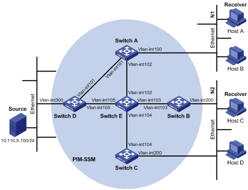
Table 5 Interface and IP address assignment
|
Device |
Interface |
IP address |
Device |
Interface |
IP address |
|
Switch A |
Vlan-int100 |
10.110.1.1/24 |
Switch D |
Vlan-int300 |
10.110.5.1/24 |
|
Switch A |
Vlan-int101 |
192.168.1.1/24 |
Switch D |
Vlan-int101 |
192.168.1.2/24 |
|
Switch A |
Vlan-int102 |
192.168.9.1/24 |
Switch D |
Vlan-int105 |
192.168.4.2/24 |
|
Switch B |
Vlan-int200 |
10.110.2.1/24 |
Switch E |
Vlan-int104 |
192.168.3.2/24 |
|
Switch B |
Vlan-int103 |
192.168.2.1/24 |
Switch E |
Vlan-int103 |
192.168.2.2/24 |
|
Switch C |
Vlan-int200 |
10.110.2.2/24 |
Switch E |
Vlan-int102 |
192.168.9.2/24 |
|
Switch C |
Vlan-int104 |
192.168.3.1/24 |
Switch E |
Vlan-int105 |
192.168.4.1/24 |
Configuration procedure
1. Assign an IP address and subnet mask to each interface, as shown in Figure 19. (Details not shown.)
2. Configure OSPF on the switches in the PIM-SSM domain. (Details not shown.)
3. Enable IP multicast routing, IGMP, and PIM-SM:
# On Switch A, enable IP multicast routing.
<SwitchA> system-view
[SwitchA] multicast routing
[SwitchA-mrib] quit
# Enable IGMPv3 on the receiver-side interface (VLAN-interface 100).
[SwitchA] interface vlan-interface 100
[SwitchA-Vlan-interface100] igmp enable
[SwitchA-Vlan-interface100] igmp version 3
[SwitchA-Vlan-interface100] quit
# Enable PIM-SM on the other interfaces.
[SwitchA] interface vlan-interface 101
[SwitchA-Vlan-interface101] pim sm
[SwitchA-Vlan-interface101] quit
[SwitchA] interface vlan-interface 102
[SwitchA-Vlan-interface102] pim sm
[SwitchA-Vlan-interface102] quit
# Enable IP multicast routing, IGMP, and PIM-SM on Switch B and Switch C in the same way Switch A is configured. (Details not shown.)
# Enable IP multicast routing and PIM-SM on Switch D and Switch E in the same way Switch A is configured. (Details not shown.)
4. Configure the SSM group range:
# Configure the SSM group range 232.1.1.0/24 on Switch A.
[SwitchA] acl basic 2000
[SwitchA-acl-ipv4-basic-2000] rule permit source 232.1.1.0 0.0.0.255
[SwitchA-acl-ipv4-basic-2000] quit
[SwitchA] pim
[SwitchA-pim] ssm-policy 2000
[SwitchA-pim] quit
# Configure the SSM group range on Switch B, Switch C, Switch D and Switch E in the same way Switch A is configured. (Details not shown.)
Verifying the configuration
# Display PIM information on Switch A.
[SwitchA] display pim interface
Interface NbrCnt HelloInt DR-Pri DR-Address
Vlan101 1 30 1 192.168.1.2
Vlan102 1 30 1 192.168.9.2
# Send an IGMPv3 report from Host A to join the multicast source and group (10.110.5.100/24, 232.1.1.1). (Details not shown.)
# Display the PIM routing table on Switch A.
[SwitchA] display pim routing-table
Total 0 (*, G) entry; 1 (S, G) entry
(10.110.5.100, 232.1.1.1)
Protocol: pim-ssm, Flag: ACT
UpTime: 00:13:25
Upstream interface: Vlan-interface101
Upstream neighbor: 192.168.1.2
RPF prime neighbor: 192.168.1.2
Downstream interface(s) information:
Total number of downstreams: 1
1: Vlan-interface100
Protocol: igmp, UpTime: 00:13:25, Expires: 00:03:25
# Display the PIM routing table on Switch D.
[SwitchD] display pim routing-table
Total 0 (*, G) entry; 1 (S, G) entry
(10.110.5.100, 232.1.1.1)
Protocol: pim-ssm, Flag: LOC
UpTime: 00:12:05
Upstream interface: Vlan-interface300
Upstream neighbor: NULL
RPF prime neighbor: NULL
Downstream interface(s) information:
Total number of downstreams: 1
1: Vlan-interface105
Protocol: pim-ssm, UpTime: 00:12:05, Expires: 00:03:25
The output shows that switches on the SPT path (Switch A and Switch D) have generated the correct (S, G) entries.
Troubleshooting PIM
A multicast distribution tree cannot be correctly built
Symptom
No multicast forwarding entries are established on the routers (including routers directly connected with multicast sources or receivers) in a PIM network. This means that a multicast distribution tree cannot be built correctly.
Solution
To resolve the problem:
1. Use display ip routing-table to verify that a unicast route to the multicast source or the RP is available.
2. Use display pim interface to verify PIM information on each interface, especially on the RPF interface. If PIM is not enabled on the interfaces, use pim dm or pim sm to enable PIM-DM or PIM-SM for the interfaces.
3. Use display pim neighbor to verify that the RPF neighbor is a PIM neighbor.
4. Verify that PIM and IGMP are enabled on the interfaces that directly connect to the multicast sources or the receivers.
5. Use display pim interface verbose to verify that the same PIM mode is enabled on the RPF interface on a router and the connected interface of the router's RPF neighbor.
6. Use display current-configuration to verify that the same PIM mode is enabled on all routers. For PIM-SM, verify that the BSR and C-RPs are correctly configured.
7. If the problem persists, contact H3C Support.
Multicast data is abnormally terminated on an intermediate router
Symptom
An intermediate router can receive multicast data successfully, but the data cannot reach the last-hop router. An interface on the intermediate router receives multicast data but does not create an (S, G) entry in the PIM routing table.
Solution
To resolve the problem:
1. Use display current-configuration to verify the multicast forwarding boundary settings. Use multicast boundary to change the multicast forwarding boundary settings to make the multicast packet able to cross the boundary.
2. Use display current-configuration to verify the multicast source policy. Change the ACL rule defined in the source-policy command so that the source/group address of the multicast data can pass ACL filtering.
3. If the problem persists, contact H3C Support.
An RP cannot join an SPT in PIM-SM
Symptom
An RPT cannot be correctly built, or an RP cannot join the SPT toward the multicast source.
Solution
To resolve the problem:
1. Use display ip routing-table to verify that a unicast route to the RP is available on each router.
2. Use display pim rp-info to verify that the dynamic RP information is consistent on all routers.
3. Use display pim rp-info to verify that the same static RPs are configured on all routers on the network.
4. If the problem persists, contact H3C Support.
An RPT cannot be built or multicast source registration fails in PIM-SM
Symptom
The C-RPs cannot unicast advertisement messages to the BSR. The BSR does not advertise BSMs containing C-RP information and has no unicast route to any C-RP. An RPT cannot be correctly established, or the source-side DR cannot register the multicast source with the RP.
Solution
To resolve the problem:
1. Use display ip routing-table on each router to view routing table information. Verify that unicast routes to the C-RPs and the BSR are available on each router and that a route is available between each C-RP and the BSR.
2. Use display pim bsr-info to verify that the BSR information exists on each router.
3. Use display pim rp-info to verify that the RP information is correct on each router.
4. Use display pim neighbor to verify that PIM neighboring relationship has been correctly established among the routers.
5. If the problem persists, contact H3C Support.