- Table of Contents
- Related Documents
-
| Title | Size | Download |
|---|---|---|
| 01-Text | 333.40 KB |
Overview
The PSR150-A1 is an AC-input and DC-output power module. The PSR150-D1 is a DC-input and DC-output power module. Both power modules provide an output voltage of 12 V and a maximum output of 150 W.
These power modules have the following features:
· Provide output overvoltage, short-circuit, overcurrent, and overtemperature protections. See Table 1 for the protection and auto-recovery features of the power modules.
· Two power modules can be connected in parallel to achieve 1+1 redundancy and load sharing.
· Hot swappable. When you hot swap a power module, make sure the device can operate correctly with the remaining power modules.
Table 1 Protection and auto-recovery features
|
Protection function |
Protection state |
Support for auto-recovery |
|
Output overvoltage protection |
The power module is latched and does not supply power. |
No |
|
Short-circuit protection |
The power module does not supply power. |
Automatically restores power supply after the short circuit condition is resolved |
|
Overcurrent protection |
The power module does not supply power. |
Automatically restores power supply after the output current decreases to an acceptable range |
|
Overtemperature protection |
The power module does not supply power. |
Automatically restores power supply after the temperature decreases to an acceptable range |
|
|
IMPORTANT: After a power module is latched, it cannot restore power supply automatically after the problems are resolved. Follow this procedure to restore the power module operation: 1. Disconnect the power cord from the external power supply system. 2. Disconnect the power cord from the power module. 3. Wait a few seconds and then connect the power cord to the power module. 4. Connect the power cord to the external power supply system. |
Technical specifications
Table 2 Technical specifications
|
Item |
Specifications |
|
Rated voltage range |
· PSR150-A1 ¡ AC input: 100 VAC to 240 VAC @ 50 Hz or 60 Hz ¡ DC input: 240 VDC · PSR150-D1: –48 VDC to –60 VDC |
|
Max voltage range |
· PSR150-A1 ¡ AC input: 90 VAC to 264 VAC @ 47 Hz or 63 Hz ¡ DC input: 192 to 290 VDC · PSR150-D1: –36 VDC to –72 VDC |
|
Output voltage |
12 V |
|
Max output current |
12.5 A |
|
Max output power |
150 W |
|
Dimensions (H × W × D) |
41.1 × 101.6 × 177 mm (1.62 × 4 × 6.97 in) |
|
Operating temperature |
–5°C to +55°C (25°F to 131°F) |
|
Storage temperature |
–40°C to +70°C (–40°F to +158°F) |
Front panel
Figure 1 PSR150-A1 AC power module
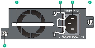
|
(1) Handle |
(2) Bail latch |
|
(3) AC-input power receptacle |
(4) Captive screws |
Figure 2 PSR150-D1 DC power module
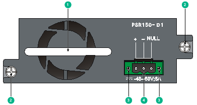
|
(1) Handle |
(2) Captive screws |
|
(3) Screw holes for securing the DC power cord plug |
(4) DC-input power receptacle |
Installing and removing the power module
To prevent device damage and personal injury, strictly follow the installation and removal procedures illustrated in Figure 3 and Figure 4, respectively.
Figure 3 Installation procedure
![]()
![]()
Safety guidelines
To prevent device damage and bodily injury, follow these restrictions and guidelines when you install or remove the power module:
· Wear an ESD wrist strap and make sure the wrist strap makes good skin contact.
· Before installing the power module, make sure the operating voltage of the external power supply system is as required by the power module, and the output voltage of the power module is as required by the powered device.
· To avoid bodily injury, do not touch any bare wire or terminal.
· Never place the power module in a wet area and prevent fluid from flowing into the power module.
· To avoid power module damage, do not open the power module. When the internal circuits or components of the power module fail, contact H3C Support.
Tools
Prepare the following tools for installation and removal:
· Flat-blade screwdriver
· Phillips screwdriver
· ESD wrist strap
Installing and removing the power module
|
|
CAUTION: Before installing or removing the power module, make sure no power cord is connected to the power module. |
The installation and removal procedures are similar for the PSR150-A1 and PSR150-D1 power modules. The following procedures use the PSR150-A1 power module as an example.
Installing the power module
1. Wear an ESD wrist strap, and make sure the wrist strap makes good skin contact and is reliably grounded.
2. Unpack the power module and verify that the input mode of the power module is as required.
3. Remove the filler panel, if any, from the target power module slot.
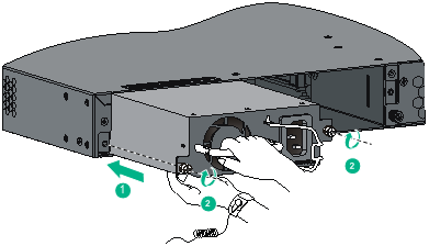
4. Correctly orient the power module. Grasping the module handle with one hand and supporting the module bottom with the other, insert the module slowly into the slot along the guide rails. See callout 1 in Figure 5.
To prevent damage to the power module or the connector on the backplane of the powered device, insert the power module gently.
If you insert the power module upside down, you will encounter a hard resistance because of the special structure designs of the slot and power module. You need to pull out the power module, orient it correctly, and insert it again.
5. Use a Phillips screwdriver to fasten the captive screws on the power module to secure it in the chassis. See callout 2 in Figure 5.
If the captive screw cannot be tightly fastened, examine the installation of the power module.
Figure 5 Installing the power module
Removing the power module
1. Wear an ESD wrist strap, and make sure the wrist strap makes good skin contact and is reliably grounded.
2. Disconnect the power cord from the power module and the external power supply.
3. Face the power module to be removed from the powered device.
4. Use a Phillips screwdriver to loosen the captive screws on the power module until the captive screws are disengaged from the powered device.
5. Grasping the handle of the power module with one hand, pull it part way out. Then supporting the power module bottom with the other hand, pull the power module slowly out of the slot along the guide rails.
6. Put the removed power module into an antistatic bag.
Connecting the power cord
Use an AC power cord to connect an AC power module to the external AC power supply system. Use a DC power cord to connect a DC power module to the external DC power supply system.
Connecting an AC power cord
1. As shown by Figure 6, pull the bail latch leftward.
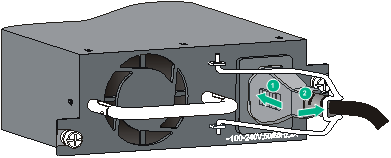
2. As shown by callout 1 in Figure 7, connect one end of the AC power cord to the AC-input power receptacle.
3. As shown by callout 2 in Figure 7, pull the bail latch rightward to secure the power cord plug in place.
4. Connect the other end of the AC power cord to the external AC power supply system.
Figure 6 Connecting an AC power cord (1)
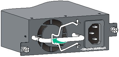
Figure 7 Connecting an AC power cord (2)
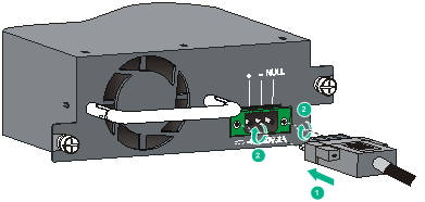
Connecting a DC power cord
1. Correctly orient the DC power cord plug, and insert it into the DC-input power receptacle on the power module.
If you insert the plug upside down, you will feel hard resistance because of the special structure designs of the DC-input power receptacle and the plug. You need to remove the plug, orient it correctly, and insert it again.
2. Use a flat-blade screwdriver to fasten the two screws on the DC power cord plug to secure the plug to the DC-input power receptacle, as shown by callout 2 in Figure 8.
3. Connect the other end of the DC power cord to the external DC power supply system.
Figure 8 Connecting a DC power cord