- Table of Contents
- Related Documents
-
| Title | Size | Download |
|---|---|---|
| 01-EVB configuration | 373.1 KB |
Configuration restrictions and guidelines
EVB and feature configuration restrictions
Specifying a default VSI manager
Configuring VDP negotiation parameters
Configuring an S-channel interface or S-channel aggregate interface
Enabling the RR mode for an S-channel
Disabling MAC address learning for an S-channel
Configuring a VSI interface or VSI aggregate interface
Creating a VSI interface or VSI aggregate interface
Activating a VSI interface or VSI aggregate interface
Displaying and maintaining EVB
Configuring EVB
Overview
Edge Virtual Bridging (EVB) allows virtual machines (VMs) on a physical server to obtain bridge relay services through a common bridge port. It enables coordinated configuration and management of bridge services for VMs.
Data center virtualization includes network virtualization, storage virtualization, and server virtualization. Server virtualization uses specific virtualization software such as VMware to create VMs on a single physical server. Each VM operates independently and has its own operating system, applications, and virtual hardware environments, as shown in Figure 1.
Figure 1 Server virtualization
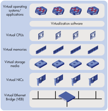
VMs on a physical server communicate with each other or with the outside network through a Virtual Ethernet Bridge (VEB). VEBs are implemented through software or hardware such as NICs. Both implementation methods have the following limitations:
· Lack of traffic monitoring capabilities such as packets statistics, traffic mirroring, and NetStream.
· Lack of network policy enforcement capabilities, such as QoS.
· Lack of management scalability, especially in unified deployment of the internal server network and the external network.
EVB solves these limitations. It uses a physical switch (called EVB bridge) to switch traffic for VMs on a directly connected physical server (called EVB station). EVB implements traffic policing, network policy enforcement, and unified network deployment and management for VMs.
Basic concepts
Figure 2 shows the components on the EVB station and EVB bridge.
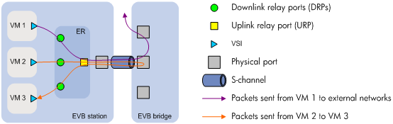
· Edge Relay—An ER transfers packets between one URP and one or more DRPs. An ER has one or more DRPs and one URP. Both URP and DRPs are called ER ports. An EVB station can have multiple ERs.
· S-channel—A point-to-point S-VLAN established between a Port-mapping S-VLAN component in an EVB station and a Port-mapping S-VLAN component in an EVB bridge. An S-channel corresponds to the URP of an ER. On an EVB bridge, the end point of an S-channel is known as an S-channel interface. An S-channel is identified by the S-VLAN Identifier (SVID) and the S-channel Identifier (SCID), and the two values together are called an (SCID, SVID) pair.
· Virtual Station Interface—A VSI is a port on a VM that directly connects to the DRP of an ER. A VSI is associated with a logical entity called VSI instance, which is identified by the VSI Instance Identifier (VSIID). A VSI is associated with a virtual interface called VSI interface on the EVB bridge port to implement VM traffic management and policy configuration. A VSI interface can be considered a subinterface of an S-channel.
· Reflective Relay—RR is an operation mode in which a received frame on a port that supports this function can be forwarded out of the same port. The EVB bridge uses this mode to forward traffic among VMs on an EVB station, as shown in Figure 2.
EVB working mechanism
The following basic concepts describe EVB station and EVB bridge communication:
· S-channel Discovery and Configuration Protocol—CDCP is used to configure S-channels between stations and bridges. When a station creates or deletes an S-channel, CDCP sends a CDCP TLV in an LLDP packet that is addressed using the nearest non-TPMR bridge address to the bridge. The bridge creates or deletes the S-channel.
· VSI Discovery and Configuration Protocol—VDP manages the association between a VSI and a station-facing bridge port (SBP) on a bridge. VDP uses the Edge Control Protocol (ECP) to carry VDP TLVs. A VDP TLV contains the VSIID, VSI type, and VSI version. The bridge uses the VSI interfaces to manage traffic for VMs.
· VSI manager—A VSI manager stores network policies such as VSI traffic management and deploys the policies when a VM accesses the network.
? When a station creates a VM, it sends a VDP pre-associate, pre-associate with resource reservation, or associate packet to the bridge. The bridge sends the request to a VSI manager, and the VSI manager notifies the bridge to create a VSI interface and apply policies.
? When a station shuts down a VM, it sends a VDP de-associate packet to the bridge. The bridge sends the request to the VSI manager, and the VSI manager notifies the bridge to delete the VSI interface.
An EVB station and an EVB bridge perform the following steps to manage VM traffic:
1. Use CDCP to establish an S-channel.
2. Exchange EVB TLVs through LLDP to negotiate EVB capabilities such as RR, ECP parameters, and VDP parameters for the S-channel.
3. Use VDP to associate the VSIs of VMs with the bridge port.
Protocols and standards
IEEE P802.1Qbg/D2.2, Draft Standard for Local and Metropolitan Area Networks—MAC Bridges and Virtual Bridged Local Area Networks - Amendment XX: Edge Virtual Bridging
Traffic received from an EVB-enabled interface can be forwarded only through interface modules that support EVB.
Licensing requirements
EVB requires a license to run on the device. For information about obtaining a license, see Fundamentals Configuration Guide.
Configuration restrictions and guidelines
EVB and feature compatibility
Table 1 shows features incompatible with EVB and the references for these features.
Table 1 Features incompatible with EVB
|
Feature |
Reference |
|
EVI |
EVI Configuration Guide |
|
VXLAN |
VXLAN Configuration Guide |
|
MPLS L2VPN |
MPLS Configuration Guide |
|
VLAN mapping |
Layer 2—LAN Switching Configuration Guide |
|
QinQ |
|
|
MAC VLAN |
|
|
Voice VLAN |
|
|
MAC authentication |
Security Configuration Guide |
|
Port security |
EVB and feature configuration restrictions
When you configure an EVB-enabled interface, follow these restrictions and guidelines:
· Do not create an Ethernet service instance for the interface, and vice versa.
· Do not set the interface to operate in route mode. For more information about Ethernet interface link modes, see Interface Configuration Guide.
· If the interface is a Layer 2 Ethernet interface or Layer 2 aggregate interface in a VLAN, it does not support Layer 3 services or Layer 2 multicast services.
· Interfaces in multiport unicast MAC address entries cannot forward traffic received from the interface. For more information about multiport unicast MAC address entries, see Layer 2—LAN Switching Configuration Guide.
· Do not configure the interface as the source or destination port for a mirroring group. For more information about mirroring groups, see Network Management and Monitoring Configuration Guide.
EVB configuration task list
This document only describes EVB bridge configuration. For information about EVB station configuration, see the station manual.
|
Tasks at a glance |
|
(Optional.) Specifying a default VSI manager |
|
(Optional.) Configuring VDP negotiation parameters |
|
(Optional.) Configuring an S-channel: · Configuring an S-channel interface or S-channel aggregate interface |
|
(Optional.) Configuring a VSI interface or VSI aggregate interface: |
Enabling EVB
Perform this task to enable EVB on an interface that directly connects to a station. For VSI filter configuration (see "Configuring a VSI filter") to take effect, you must configure the interface to operate in trunk mode.
A default S-channel is created on an interface after you enable EVB on the interface. Both the SCID and SVID are 1. After an S-channel is created, an S-channel interface or S-channel aggregate interface is automatically created and operates in access mode.
Configuration restrictions and guidelines
When you enable EVB, follow these restrictions and guidelines:
· Do not enable both EVB and TRILL on the same interface. For more information about TRILL, see TRILL Configuration Guide.
· Do not assign ports that are enabled with EVB but not configured with the trill evb-support command to the same VLAN as ports that are enabled with TRILL. For more information about the trill evb-support command, see TRILL Command Reference.
Configuration procedure
To enable EVB:
|
Step |
Command |
Remarks |
|
1. Enter system view. |
system-view |
N/A |
|
2. Enter Layer 2 Ethernet interface view or Layer 2 aggregate interface view. |
interface interface-type interface-number |
N/A |
|
3. Enable EVB. |
evb enable |
By default, EVB is disabled on an interface. |
Configuring LLDP
You must configure LLDP because EVB uses LLDP to transmit CDCP TLVs and CDCP TLVs are carried by the LLDP packet that is addressed using the nearest non-TPMR bridge address.
For more information about the lldp global enable, lldp enable and lldp agent nearest-nontpmr admin-status txrx commands, see Layer 2—LAN Switching Command Reference.
To configure LLDP:
|
Step |
Command |
Remarks |
|
1. Enter system view. |
system-view |
N/A |
|
2. Enable LLDP globally. |
lldp global enable |
By default, LLDP is disabled globally. |
|
3. Enter Layer 2 Ethernet interface view or Layer 2 aggregate interface view. |
interface interface-type interface-number |
N/A |
|
4. Enable LLDP on the interface |
lldp enable |
By default, LLDP is enabled on an interface. |
|
5. Configure the Nearest non-TPMR Bridge agent for LLDP to operate in TxRx mode. |
lldp agent nearest-nontpmr admin-status txrx |
The default mode is disable. |
Specifying a default VSI manager
When the bridge receives a VDP packet (except for de-associate packets) from a station, it obtains VSI interface resources and policies for the station from the VSI manager specified in the VDP packet.
The VSI manager ID TLV in a VDP packet carries an IP address of a VSI manager. If the value for the TLV is 0, the VDP packet does not contain a VSI manager IP address. Perform this task to specify a default VSI manager for the bridge.
To specify a default VSI manager:
|
Step |
Command |
Remarks |
|
1. Enter system view. |
system-view |
N/A |
|
2. Specify a default VSI manager. |
evb default-manager { { ip ipv4-address | ipv6 ipv6-address | name name } [ port port-number ] | local-server } |
By default, no default VSI manager is specified. |
Configuring VDP negotiation parameters
After a station sends a VDP request other than a De-Associate request to the bridge, the bridge requests the VSI interface resources and policies from the VSI manager. If the bridge does not receive a response from the VSI manager before the VDP response-wait-delay time expires, the VDP negotiation fails. The VDP response-wait-delay time on the EVB bridge is calculated by using the following formula:
VDP response-wait-delay time (seconds) = 2VDP resource-wait-delay × 10—5.
The value of the VDP resource wait-delay exponent is the larger of the values proposed by the station and bridge through EVB TLV.
When a Pre-Associate, Pre-Associate with Resource Reservation, or Associate request from a station is successfully handled, the VSI manager notifies the bridge to create a VSI interface for the corresponding VM. Then the bridge starts a VDP keepalive timer for the VSI interface. If the bridge does not receive a keepalive from the station before the timer expires, it releases resources reserved for the association. The VDP keepalive time is calculated by using the following formula:
VDP keepalive time (seconds) = 1.5 × [ 2VDP keepalive + (2 × ECP maximum retransmission time + 1) × 2ECP retransmission ] × 10—5.
The values assigned to the VDP keepalive exponent, the ECP maximum retransmission time, and the ECP retransmission exponent are the larger of the values proposed for each by the station and bridge through EVB TLV.
To configure VDP negotiation parameters:
|
Step |
Command |
Remarks |
|
1. Enter system view. |
system-view |
N/A |
|
2. Enter Layer 2 Ethernet interface view or Layer 2 aggregate interface view. |
interface interface-type interface-number |
N/A |
|
3. Set the VDP resource-wait-delay timer exponent. |
evb vdp timer resource-wait-delay exponent value |
The default is 20. |
|
4. Set the VDP keepalive timer exponent. |
evb vdp timer keepalive exponent value |
The default is 20. |
Configuring an S-channel
Creating an S-channel
An S-channel is automatically created by CDCP, and the system automatically saves the configuration in the configuration file on the bridge. You can perform this task to manually create an S-channel. If you create an S-channel that has the same number as an automatically created S-channel, the (SCID, SVID) pair configuration for the automatically created S-channel takes precedence over the (SCID, SVID) pair configuration for the manually created S-channel.
Creating an S-channel also creates an S-channel interface or S-channel aggregate interface. Removing an S-channel also removes the S-channel interface or S-channel aggregate interface. The S-channel interface or S-channel aggregate interface associated with a manually created S-channel operates in access mode. The S-channel interface or S-channel aggregate interface associated with an automatically created S-channel operates in trunk mode.
An S-channel interface is associated with the S-channel that is created on a Layer 2 Ethernet interface. An S-channel aggregate interface is associated with the S-channel that is created on a Layer 2 aggregate interface.
When you create an S-channel, follow these restrictions and guidelines:
· Create an S-channel on an interface with EVB enabled.
· Do not use the SCID or SVID being used by any other S-channels.
· To manually create or remove an S-channel, disable CDCP.
To create an S-channel:
|
Step |
Command |
Remarks |
|
1. Enter system view. |
system-view |
N/A |
|
2. Enter Layer 2 Ethernet interface view or Layer 2 aggregate interface view. |
interface interface-type interface-number |
N/A |
|
3. Create an S-channel. |
evb s-channel channel-id [ service-vlan svlan-id ] |
By default, only an automatically created default S-channel (with both SCID and SVID as 1) exists on an interface with EVB enabled. |
Configuring an S-channel interface or S-channel aggregate interface
|
Step |
Command |
Remarks |
|
1. Enter system view. |
system-view |
N/A |
|
2. Enter S-channel interface view or S-channel aggregate interface view. |
interface { s-channel | schannel-aggregation } interface-number:channel-id |
N/A |
|
3. (Optional.) Set the expected bandwidth of the interface. |
bandwidth bandwidth-value |
By default, the expected bandwidth of an interface is the default maximum bandwidth of the physical port to which the interface belongs. |
|
4. (Optional.) Restore the default settings for the interface. |
default |
N/A |
|
5. (Optional.) Set a description for the interface. |
description text |
The default description information is "interface name Interface." |
|
6. Bring up the interface. |
undo shutdown |
By default, the interface is up. |
Enabling the RR mode for an S-channel
EVB TLVs exchanged through LLDP allow an EVB station and EVB bridge to negotiate the RR mode. If the EVB bridge supports the RR mode, when the EVB station requests the use of the RR mode, the bridge performs the following operations:
· Automatically enables the RR mode for the S-channel.
· Saves the configuration in the configuration file on the bridge.
You can perform this task to manually enable the RR mode for an S-channel.
To enable the RR mode for an S-channel:
|
Step |
Command |
Remarks |
|
1. Enter system view. |
system-view |
N/A |
|
2. Enter S-channel interface view or S-channel aggregate interface view. |
interface { s-channel | schannel-aggregation } interface-number:channel-id |
N/A |
|
3. Enable the RR mode for the S-channel. |
evb reflective-relay |
By default, the RR mode is disabled for an S-channel. |
Disabling MAC address learning for an S-channel
Perform this task to manually disable the MAC address learning feature for an S-channel.
Follow these restrictions and guidelines when you disable MAC address learning for an S-channel:
· For the bridge to successfully forward traffic for VMs on the EVB station, do not disable MAC address learning on an S-channel with the RR mode disabled.
· After you disable the MAC address learning function for an S-channel, the bridge will discard packets with an unknown source MAC address.
· The undo evb mac-learning forbidden command and the mac-address mac-learning enable command must be configured together to avoid communication interruption. For more information about the mac-address mac-learning enable command, see Layer 2—LAN Switching Command References.
To disable MAC address learning for an S-channel:
|
Command |
Remarks |
|
|
1. Enter system view. |
system-view |
N/A |
|
2. Enter interface view. |
· Enter S-channel interface view: · Enter S-channel aggregate interface view: |
N/A |
|
3. Disable MAC address learning for the S-channel. |
evb mac-learning forbidden |
By default, the MAC address learning function is enabled for an S-channel. |
Configuring a VSI interface or VSI aggregate interface
Creating a VSI interface or VSI aggregate interface
|
|
IMPORTANT: When the total number of VSI interfaces and VSI aggregate interfaces on the device exceeds 512, make sure the VDP keepalive exponent is larger than the default value. If the exponent is not larger than the default value, some VSI interfaces or VSI aggregate interfaces might be automatically deleted. |
VSI interfaces or VSI aggregate interfaces are typically created by a VSI manager. You can perform this task to create a VSI interface on an S-channel interface or create a VSI aggregate interface on an S-channel aggregate interface. In addition, you can perform this task to modify the Pre-Associate and Associate properties of a VSI interface or VSI aggregate interface.
Removing an S-channel also removes all its VSI interfaces and VSI aggregate interfaces.
To create a VSI interface or VSI aggregate interface:
|
Step |
Command |
Remarks |
|
1. Enter system view. |
system-view |
N/A |
|
2. Enter S-channel interface view or S-channel aggregate interface view. |
interface { s-channel | schannel-aggregation } interface-number:channel-id |
N/A |
|
3. Create a VSI interface or VSI aggregate interface. |
evb vsi vsi-local-id { association | pre-association } |
By default, no VSI interface or VSI aggregate interfaces exist on an S-channel. |
Configuring a VSI filter
The EVB bridge uses a VSI filter to identify VSI traffic for a VM. Typically a VSI manager assigns filters to VMs. Perform this task to manually create or remove a VSI filter.
A VSI filter contains a set of VID values, MAC addresses, and group ID values. EVB supports the following filter info formats:
· VLAN ID.
· VLAN ID + MAC.
· Group ID + VLAN ID.
· Group ID + VLAN ID + MAC.
When you configure a VSI filter on a VSI interface, follow these restrictions and guidelines:
· For the VSI filter configuration to take effect, make sure the S-channel interface to which the VSI interface belongs operates in trunk mode.
· When you create a VSI filter, the following interfaces automatically permit the VLAN contained in the VSI filter:
? The S-channel interface to which the VSI interface belongs.
? The Layer 2 Ethernet interface where the S-channel that is associated with the S-channel interface is created.
· When you delete a VSI filter, the following interfaces automatically deny the VLAN in the filter if the VSI filters on the other VSI interfaces created on the same S-channel interface do not contain the VLAN:
? The S-channel interface to which the VSI interface belongs.
? The Layer 2 Ethernet interface where the S-channel that is associated with the S-channel interface is created.
· Do not create a VSI filter that contains the same VLAN on the same VSI interface or on other VSI interfaces that belong to the same S-channel interface. If you do so, the system displays an error message.
· Disabling MAC address learning for an S-channel prevents the traffic from the VSI from being forwarded if the VSI filter contains the VLAN to which the traffic belongs.
· Activate a VSI interface after configuring a VSI filter, and deactivate a VSI interface before removing a VSI filter.
When you configure a VSI filter on a VSI aggregate interface, follow these restrictions and guidelines:
· For the VSI filter configuration to take effect, make sure the S-channel aggregate interface to which the VSI aggregate interface belongs operates in trunk mode.
· When you create a VSI filter, the following interfaces automatically permit the VLAN contained in the VSI filter:
? The S-channel aggregate interface to which the VSI aggregate interface belongs.
? The Layer 2 aggregate interface where the S-channel that is associated with the S-channel aggregate interface is created.
· When you delete a VSI filter, the following interfaces automatically deny the VLAN in the filter if the VSI filters on the other VSI aggregate interfaces created on the same S-channel aggregate interface do not contain the VLAN:
? The S-channel aggregate interface to which the VSI aggregate interface belongs.
? The Layer 2 aggregate interface where the S-channel that is associated with the S-channel aggregate interface is created.
· Do not create a VSI filter that contains the same VLAN on the same VSI aggregate interface or on other VSI aggregate interfaces that belong to the same S-channel aggregate interface. If you do so, the system displays an error message.
· Activate a VSI aggregate interface after configuring a VSI filter, and deactivate a VSI aggregate interface before removing a VSI filter.
To configure a VSI filter:
|
Step |
Command |
Remarks |
|
1. Enter system view. |
system-view |
N/A |
|
2. Enter VSI interface view or VSI aggregate interface view. |
interface { s-channel | schannel-aggregation } interface-number:channel-id.vsi-local-id |
N/A |
|
3. Configure a VSI filter. |
evb vsi filter [ group group-id ] vlan vlan-id [ mac mac-address ] |
By default, no VSI filters exist. |
Activating a VSI interface or VSI aggregate interface
Traffic policy configuration on a VSI interface or VSI aggregate interface takes effect only when the VSI interface or VSI aggregate interface is activated. When a VSI interface or VSI aggregate interface is not activated, do not configure any settings other than filters on either interface. For more information about traffic policing, see ACL and QoS Configuration Guide.
Activate a VSI interface or VSI aggregate interface after configuring a VSI filter, and deactivate a VSI interface or VSI aggregate interface before removing a VSI filter.
To activate a VSI interface or VSI aggregate interface:
|
Step |
Command |
Remarks |
|
1. Enter system view. |
system-view |
N/A |
|
2. Enter VSI interface view or VSI aggregate interface view. |
interface { s-channel | schannel-aggregation } interface-number:channel-id.vsi-local-id |
N/A |
|
3. (Optional.) Set the expected bandwidth of the VSI interface or VSI aggregate interface. |
bandwidth bandwidth-value |
By default, the expected bandwidth of a VSI interface or VSI aggregate interface is the default maximum bandwidth of the physical port to which the interface belongs. |
|
4. (Optional.) Restore the default settings for the VSI interface or VSI aggregate interface. |
default |
N/A |
|
5. (Optional.) Set a description for the VSI interface or VSI aggregate interface. |
description text |
The default description information is "interface name Interface." |
|
6. Activate the VSI interface or VSI aggregate interface. |
evb vsi active |
By default, no VSI interface or VSI aggregate interface is activated. |
Displaying and maintaining EVB
Execute display commands in any view and the reset command in user view.
|
Command |
|
|
Display CDCP negotiation information. |
display evb cdcp [ interface interface-type interface-number ] |
|
Display S-channel EVB TLV negotiation information. |
display evb evb-tlv [ interface interface-type { interface-number | interface-number:channel-id } ] |
|
Display S-channel information. |
display evb s-channel [ interface interface-type interface-number ] |
|
Display EVB summary. |
display evb summary |
|
Display VSI interface information. |
display evb vsi [ verbose ] [ interface interface-type { interface-number | interface-number:channel-id | interface-number:channel-id.vsi-local-id } ] |
|
Display information about an S-channel interface, an S-channel aggregate interface, a VSI interface, or a VSI aggregate interface. |
display interface [ { s-channel | schannel-aggregation } [ interface-number:channel-id | interface-number:channel-id.vsi-local-id ] ] [ brief [ description | down ] ] |
|
Clear statistics for an S-channel interface, an S-channel aggregate interface, a VSI interface, or a VSI aggregate interface. |
reset counters interface [ { s-channel | schannel-aggregation } [ interface-number:channel-id | interface-number:channel-id.vsi-local-id ] ] |
EVB configuration example
Network requirements
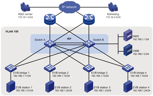
As shown in Figure 3, the Layer 2 network of a data center comprises two switches that form an IRF fabric, four EVB bridges, and four EVB stations. They communicate within VLAN 100.
Create VM 1 with MAC address 0050-5684-21C7 on EVB station 1, and set VM1 as the FTP server with a CIR of 2048 kbps and a PIR of 4096 kbps. Only the R&D center is allowed to access the network.
Configuration procedure
This section only contains EVB configurations.
Configuring the EVB bridge
# Create VLAN 100 on EVB bridge 1.
<EVB_bridge1> system-view
[EVB_bridge1] vlan 100
[EVB_bridge1-vlan100] quit
# Enable EVB on Ten-GigabitEthernet 1/1/1 that connects to EVB station 1, and configure Ten-GigabitEthernet 1/0/1 to operate in trunk mode.
[EVB_bridge1] interface ten-gigabitethernet 1/1/1
[EVB_bridge1-Ten-GigabitEthernet1/1/1] evb enable
[EVB_bridge1-Ten-GigabitEthernet1/1/1] port link-type trunk
[EVB_bridge1-Ten-GigabitEthernet1/1/1] quit
# Enable LLDP on EVB bridge 1 globally. Enable LLDP on Ten-GigabitEthernet 1/1/1, and configure the Nearest non-TPMR Bridge agent for LLDP to operate in TxRx mode.
[EVB_bridge1] lldp global enable
[EVB_bridge1] interface ten-gigabitethernet 1/1/1
[EVB_bridge1-Ten-GigabitEthernet1/1/1] lldp enable
[EVB_bridge1-Ten-GigabitEthernet1/1/1] lldp agent nearest-nontpmr admin-status txrx
[EVB_bridge1-Ten-GigabitEthernet1/1/1] quit
# Specify the IP address and port number for the default VSI manager on EVB bridge 1.
[EVB_bridge1] evb default-manager ip 192.168.1.1 port 8080
# Configure other EVB bridges in the same way. (Details not shown.)
Configuring the EVB station
# Configure the EVB station on the VMM. For more information about configuring VMs through the VMM, see the VMM manual. (Details not shown.)
Configuring the NMS
Use VAN Connection Manager of IMC on the NMS to configure network resources.
The IMC PLAT 5.2 (E0401) and IMC CRM 5.2 (E0401) versions are used in this section.
Figure 4 VAN Connection Manager
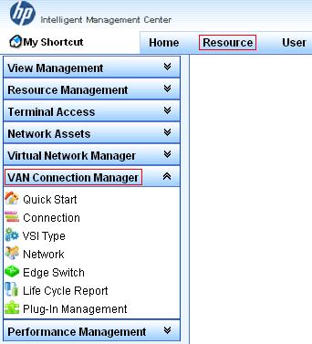
To configure the NMS, log in to IMC, click the Resource tab, and select VAN Connection Manager from the navigation tree (see Figure 4), and perform the following steps:
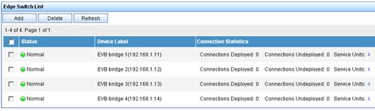
1. Add an EVB bridge (Edge Switch):
a. Select Edge Switch from the navigation tree.
b. Click Add on the page that appears.
c. Select the four devices in the IP address range of 192.168.1.11 through 192.168.1.14 from IP View.
d. Click OK.
EVB bridge 1, EVB bridge 2, EVB bridge 3, and EVB bridge 4 are displayed in the Edge Switch List page, as shown in Figure 5.
Figure 5 Edge Switch List page
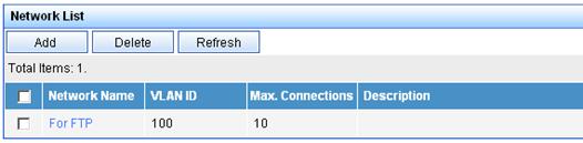
2. Add an FTP network:
Select Network from the navigation tree, click Add on the page that appears, enter For FTP for Name, 100 for VLAN ID, and 10 for Max. Connections, and click OK.
The network name For FTP is displayed in the Network List page, as shown in Figure 6.
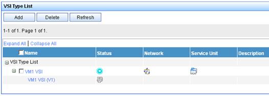
3. Define the VSI type of VM 1:
a. Select VSI Type from the navigation tree. The VSI Type List page appears.
b. Click Add.
c. On the page that appears, do the following:
- Enter VM1 VSI for Name.
- Select For FTP from the Network list, and select the Bandwidth Control and VM Access Control options.
- Enter 172.16.1.0 for Client IP and 0.0.0.255 for Wildcard Mask.
- Select BOTH from the Filtering Direction list.
- Enter 2048 for CIR (kbps) and 4096 for PIR (kbps).
d. Click Save and Release.
The VSI type VM1 VSI is displayed in the VSI Type List page, as shown in Figure 7.
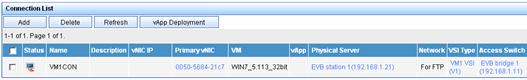
4. Bind the VSI type VM1 VSI to the vNIC of VM 1 to define the connection:
a. Select Connection from the navigation tree. The Connection List page appears.
b. Click Add.
c. On the page that appears, do the following:
- Enter VM1CON for Name.
- Click Select on the right side of the page, select the VM1 option from the popup window. Then, click OK (the MAC address 0050-5684-21c7 of VM 1 is displayed in the vNIC field).
- Select For FTP from the Network list, VM1 VSI from VSI Type, and VM1 VSI (V1) from VSI Type Version.
d. Click OK.
The connection VM1CON is displayed in the Connection List page, as shown in Figure 8.
Verifying the configuration
After VM 1 starts, the VAN Connection Manager service component of IMC deploys the VSI type VM1 VSI on EVB bridge 1. Only the R&D center can use the FTP service on VM 1.