- Table of Contents
-
- 04-Layer 3 - IP Services Configuration Examples
- 01-H3C_S7500E_DHCP_Snooping_Configuration_Examples
- 02-H3C_S7500E_GRE_with_OSPF_Configuration_Examples
- 03-H3C_S7500E_IPv6_over_IPv4_GRE_Tunnel_Configuration_Examples
- 04-H3C_S7500E_IPv6_over_IPv4_Manual_Tunneling_with_OSPFv3_Configuration_Examples
- 05-H3C_S7500E_ISATAP_Tunnel_and_6to4_Tunnel_Configuration_Examples
- 06-H3C_S7500E_IP_Unnumbered_Configuration_Examples
- 07-H3C_S7500E_Cross-Subnet_Dynamic_IP_Address_Allocation_Configuration_Examples
- Related Documents
-
| Title | Size | Download |
|---|---|---|
| 03-H3C_S7500E_IPv6_over_IPv4_GRE_Tunnel_Configuration_Examples | 141.92 KB |
H3C S7500E IPv6 over IPv4 GRE Tunnel Configuration Examples
|
Copyright © 2015 Hangzhou H3C Technologies Co., Ltd. All rights reserved. No part of this manual may be reproduced or transmitted in any form or by any means without prior written consent of Hangzhou H3C Technologies Co., Ltd. The information in this document is subject to change without notice. |
|
Contents
Example: Configuring an IPv6 over IPv4 GRE tunnel
Configuration restrictions and guidelines
Introduction
This document provides IPv6 over IPv4 GRE tunnel configuration examples.
Prerequisites
The configuration examples in this document were created and verified in a lab environment, and all the devices were started with the factory default configuration. When you are working on a live network, make sure you understand the potential impact of every command on your network.
This document assumes that you have basic knowledge of GRE.
Example: Configuring an IPv6 over IPv4 GRE tunnel
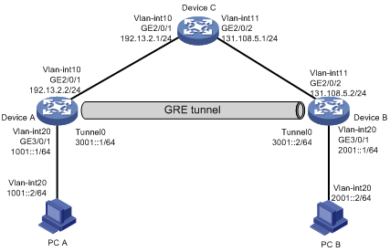
Network requirements
As shown in Figure 1, Device A, Device B, and Device C are all on an IPv4 network. Dual stack devices Device A and Device B each connect to an IPv6 host.
Configure a GRE/IPv4 tunnel between Device A and Device B, so PC A and PC B can communicate with each other over the IPv4 network.
Requirements analysis
To meet the network requirements, you must perform the following tasks:
· To enable the IPv6 hosts to communicate over the IPv4 network, specify the GRE tunnel mode as GRE/IPv4 and configure IPv6 addresses for the tunnel interfaces.
· To transmit packets between PC A and PC B through the GRE tunnel, configure a route reaching the destination network through the tunnel interface on Device A and Device B. You can configure the routes by using either of the following methods:
¡ Configure static routes, using the peer tunnel interface as the next hop or using the local tunnel interface as the outgoing interface.
¡ Enable a dynamic routing protocol on both the tunnel interfaces and the Layer 3 interfaces connected to PC A and PC B.
· For both ends of the GRE tunnel to reach each other, configure a static route reaching the remote end on Device A and Device B.
Software version used
This configuration example was created and verified on S7500E-CMW710-R7150.
Configuration restrictions and guidelines
When you configure the GRE tunnel, follow these restrictions and guidelines:
· You must configure the tunnel source address and destination address at both ends of the tunnel. The tunnel source or destination address at one end must be the tunnel destination or source address at the other end.
· Encapsulated packets cannot be forwarded on Layer 3 according to the destination IP addresses and routing tables. You must create a service loopback group of the tunnel service type to loop encapsulated packets back to the forwarding module for Layer 3 forwarding.
Configuration procedures
Configuring Device A
# Configure an IPv6 address for GigabitEthernet 3/0/1.
<DeviceA> system-view
[DeviceA] interface gigabitethernet 3/0/1
[DeviceA-GigabitEthernet3/0/1] ipv6 address 1001::1 64
[DeviceA-GigabitEthernet3/0/1] quit
# Configure other interfaces in the same way GigabitEthernet 3/0/1 is configured. (Details not shown.)
# Create a tunnel interface Tunnel 0, and specify the tunnel mode as GRE/IPv4.
[DeviceA] interface tunnel 0 mode gre
# Configure an IPv6 address for the tunnel interface Tunnel 0.
[DeviceA-Tunnel0] ipv6 address 3001::1 64
# Configure the source address of the tunnel interface Tunnel 0 as the IP address of GigabitEthernet 2/0/1.
[DeviceA-Tunnel0] source 192.13.2.2
# Configure the destination address of the tunnel interface Tunnel 0 as the IP address of GigabitEthernet 2/0/2 on Device B.
[DeviceA-Tunnel0] destination 131.108.5.2
[DeviceA-Tunnel0] quit
# Configure a static route reaching PC B through the tunnel interface Tunnel 0.
[DeviceA] ipv6 route-static 2001:: 64 tunnel 0
# Configure a static route reaching the remote end of the GRE tunnel.
[DeviceA] ip route-static 131.108.5.2 255.255.255.0 192.13.2.1
# Create service loopback group 1, and specify its service type as tunnel.
[DeviceA] service-loopback group 1 type tunnel
# Add GigabitEthernet 3/0/2 to service loopback group 1.
[DeviceA] interface gigabitethernet 3/0/2
[DeviceA-GigabitEthernet3/0/2] port service-loopback group 1
[DeviceA-GigabitEthernet3/0/2] quit
Configuring Device B
# Configure an IPv6 address for GigabitEthernet 3/0/1.
<DeviceB> system-view
[DeviceB] interface gigabitethernet 3/0/1
[DeviceB-GigabitEthernet3/0/1] ipv6 address 2001::1 64
[DeviceB-GigabitEthernet3/0/1] quit
# Configure other interfaces in the same way GigabitEthernet 3/0/1 is configured. (Details not shown.)
# Create a tunnel interface Tunnel 0, and specify the tunnel mode as GRE/IPv4.
[DeviceB] interface tunnel 0 mode gre
# Configure an IPv6 address for the tunnel interface Tunnel 0.
[DeviceB-Tunnel0] ipv6 address 3001::2 64
# Configure the source address of the tunnel interface Tunnel 0 as the IP address of GigabitEthernet 2/0/2.
[DeviceB-Tunnel0] source 131.108.5.2
# Configure the destination address of the tunnel interface Tunnel 0 as the IP address of GigabitEthernet 2/0/1 on Device A.
[DeviceB-Tunnel0] destination 192.13.2.2
[DeviceB-Tunnel0] quit
# Configure a static route reaching PC A through the tunnel interface Tunnel 0.
[DeviceB] ipv6 route-static 1001:: 64 Tunnel 0
# Configure a static route reaching the remote end of the GRE tunnel.
[DeviceB] ip route-static 192.13.2.2 255.255.255.0 131.108.5.1
# Create service loopback group 1, and specify its service type as tunnel.
[DeviceB] service-loopback group 1 type tunnel
# Add GigabitEthernet 3/0/2 to service loopback group 1.
[DeviceB] interface gigabitethernet 3/0/2
[DeviceB-GigabitEthernet3/0/2] port service-loopback group 1
[DeviceA-GigabitEthernet3/0/2] quit
Configuring Device C
# Configure an IP address for GigabitEthernet 2/0/1.
<DeviceC> system-view
[DeviceC] interface gigabitethernet 2/0/1
[DeviceC-GigabitEthernet2/0/1] ip address 192.13.2.1 24
[DeviceC-GigabitEthernet2/0/1] quit
# Configure an IP address for GigabitEthernet 2/0/2.
[DeviceC] interface gigabitethernet 2/0/2
[DeviceC-GigabitEthernet2/0/2] ip address 131.108.5.1 24
[DeviceC-GigabitEthernet2/0/2] quit
# Create service loopback group 1, and specify its service type as tunnel.
[DeviceC] service-loopback group 1 type tunnel
# Add GigabitEthernet 3/0/2 to service loopback group 1.
[DeviceC] interface gigabitethernet 3/0/2
[DeviceC-GigabitEthernet3/0/2] port service-loopback group 1
[DeviceC-GigabitEthernet3/0/2] quit
Verifying the configuration
# Verify that PC A and PC B can ping each other successfully. This example uses PC A to ping PC B.
C:\>ping6 2001::2
Pinging 2001::2
from 1001::1 with 32 bytes of data:
Reply from 2001::2: bytes=32 time<1ms
Reply from 2001::2: bytes=32 time<1ms
Reply from 2001::2: bytes=32 time<1ms
Reply from 2001::2: bytes=32 time<1ms
Ping statistics for 2001::2:
Packets: Sent = 4, Received = 4, Lost = 0 (0% loss),
Approximate round trip times in milli-seconds:
Minimum = 0ms, Maximum = 0ms, Average = 0ms
Configuration files
· Device A:
service-loopback group 1 type tunnel
#
vlan 10
#
vlan 20
#
interface GigabitEthernet2/0/1
port link-mode bridge
port access vlan 10
#
interface GigabitEthernet3/0/1
port link-mode bridge
port access vlan 20
#
interface GigabitEthernet3/0/2
port service-loopback group 1
#
interface interface Vlan-interface 10
ip address 192.13.2.2 255.255.255.0
#
interface interface Vlan-interface 20
ipv6 address 1001::1/64
#
interface Tunnel0 mode gre
ipv6 address 3001::1/64
source 192.13.2.2
destination 131.108.5.2
#
ip route-static 131.108.5.2 255.255.255.0 192.13.2.1
#
ipv6 route-static 2001:: 64 Tunnel 0
#
· Device B:
#
service-loopback group 1 type tunnel
#
vlan 11
#
vlan 20
#
interface GigabitEthernet2/0/2
port link-mode bridge
port access vlan 11
#
interface GigabitEthernet3/0/1
port link-mode bridge
port access vlan 20
#
interface GigabitEthernet3/0/2
port service-loopback group 1
#
interface interface Vlan-interface 11
ip address 131.108.5.2 255.255.255.0
#
interface interface Vlan-interface 20
ipv6 address 2001::1/64
#
interface Tunnel0 mode gre
ipv6 address 3001::2/64
source 131.108.5.2
destination 192.13.2.2
#
ip route-static 192.13.2.2 255.255.255.0 131.108.5.1
#
ipv6 route-static 1001:: 64 Tunnel 0
#
· Device C:
#
vlan 10
#
vlan 11
#
interface GigabitEthernet2/0/1
port link-mode bridge
port access vlan 10
#
interface GigabitEthernet2/0/2
port link-mode bridge
port access vlan 11
#
interface interface Vlan-interface 10
port link-mode route
ip address 192.13.2.1 255.255.255.0
#
interface interface Vlan-interface 11
port link-mode route
ip address 131.108.5.1 255.255.255.0
#
Related documentation
· H3C S7500E Switch Series Layer 3—IP Services Configuration Guide-Release 7150
· H3C S7500E Switch Series Layer 3—IP Services Command Reference-Release 7150