| Title | Size | Download |
|---|---|---|
| 01-H3C S12500 EVI with VPN Configuration Examples | 158.89 KB |
General configuration restrictions and guidelines
Example: Configuring EVI with VPN
Introduction
This document provides examples for using VPN to provide Layer 3 isolation for VLANs extended through different EVI networks across data center sites.
Ethernet Virtual Interconnect (EVI) is a MAC-in-IP technology that provides Layer 2 connectivity between distant Layer 2 network sites across an IP routed network. It is used for connecting geographically dispersed sites of a virtualized large-scale data center that requires Layer 2 adjacency.
EVI enables long-distance virtual machine workload mobility and data mobility, disaster recovery, and business continuity. For example, virtual machines can move between data center sites without changing their IP addresses, so their movements are transparent to users and do not disrupt traffic.
Prerequisites
The configuration examples in this document were created and verified in a lab environment, and all the devices were started with the factory default configuration. When you are working on a live network, make sure you understand the potential impact of every command on your network.
This document assumes that you have basic knowledge of EVI and VPN.
General configuration restrictions and guidelines
When you configure EVI, follow these restrictions and guidelines:
· For an extended VLAN at a site, you must place the VLAN's gateway on the edge device at the local site rather than a remote site.
· To use EVI, you must install a DATACENTER license.
Example: Configuring EVI with VPN
Network requirements
As shown in Figure 1:
· Use EVI to extend VLAN 10, VLAN 20, VLAN 30, and VLAN 40 across three data center sites over an IP transport network.
¡ Set up EVI network 1 to extend VLAN 10 and VLAN 20. Associate VLAN 10 and VLAN 20 with VPN instance vpn1 for Layer 3 isolation from other VLANs.
¡ Set up EVI network 2 to extend VLAN 30 and VLAN 40.
· Use EVI edge devices Switch A, Switch B, and Switch C to provide gateway services for their respective site.
¡ Make sure VLAN 10 and VLAN 20 can communicate at Layer 3.
¡ Make sure VLAN 30 and VLAN 40 can communicate at Layer 3.
¡ The gateways and IP addresses of servers or virtual machines in the VLANs must not change after they are moved from one site to another.
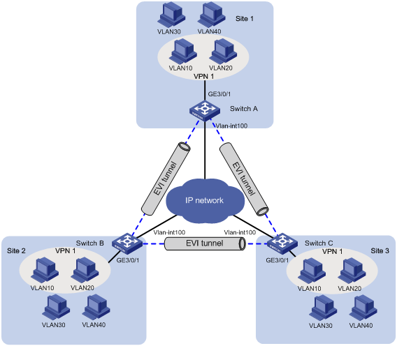
Table 1 IP address assignment
|
Device |
Interface |
IP address |
Device |
Interface |
IP address |
|
Switch A |
Loopback 0 |
1.1.1.1/32 |
Switch C |
Loopback 0 |
3.3.3.3/32 |
|
|
Loopback 1 |
1.1.1.2/32 |
|
Loopback 1 |
3.3.3.4/32 |
|
|
VLAN-interface 100 |
100.1.1.1/24 |
|
VLAN-interface 100 |
100.1.1.3/24 |
|
|
VLAN-interface 10 |
10.1.1.1/24 |
|
VLAN-interface 10 |
10.1.1.3/24 |
|
|
VLAN-interface 20 |
20.1.1.1/24 |
|
VLAN-interface 20 |
20.1.1.3/24 |
|
|
VLAN-interface 30 |
30.1.1.1/24 |
|
VLAN-interface 30 |
30.1.1.3/24 |
|
|
VLAN-interface 40 |
40.1.1.1/24 |
|
VLAN-interface 40 |
40.1.1.3/24 |
|
Switch B |
Loopback 0 |
2.2.2.2/32 |
|
|
|
|
|
Loopback 1 |
2.2.2.3/32 |
|
|
|
|
|
VLAN-interface 100 |
100.1.1.2/24 |
|
|
|
|
|
VLAN-interface 10 |
10.1.1.2/24 |
|
|
|
|
|
VLAN-interface 20 |
20.1.1.2/24 |
|
|
|
|
|
VLAN-interface 30 |
30.1.1.2/24 |
|
|
|
|
|
VLAN-interface 40 |
40.1.1.2/24 |
|
|
|
Requirements analysis
· To avoid IP address or gateway changes for virtual machines after inter-site migration, deploy VRRP as follows:
¡ Configure four VRRP groups on the EVI edge devices to provide gateway services for the extended VLANs.
¡ For all edge devices to be masters in the VRRP groups, use ACLs to filter outgoing VRRP gratuitous ARP packets in the extended VLANs.
· To forward inter-site Layer 3 VPN traffic, configure GRE tunnels between the data center sites.
Software version used
This configuration example was created and verified on S12500-CMW710-R7328P02.
Configuration restrictions and guidelines
When you configure EVI with VPN, follow these restrictions and guidelines:
|
Configuration |
Restrictions and guidelines |
|
VPN |
Each EVI network can have only one VPN instance. To assign VLANs to different VPNs, you must use different EVI networks to extend the VLANs. If you associate an interface with a VPN instance, the IP address of the interface is removed. You must reassign the IP address to the interface. |
|
EVI network ID |
· All edge devices must use the same network ID for the EVI tunnels in the same EVI network. · The EVI tunnels on an edge device must use different network IDs. |
|
Extended VLAN |
· Extended VLANs assigned to different EVI networks cannot be duplicated. · To avoid data breach, ensure that all edge devices in an EVI network maintain the same extended VLANs. |
|
Outgoing interface to the transport network |
· For data security, do not use VLAN-interface 1 as an outgoing interface. Remove transport-facing physical interfaces from VLAN 1. · Do not use the VLAN interface of an extended VLAN as an outgoing interface to the transport network. |
|
Traffic blackhole prevention |
To avoid traffic blackholes, ensure that the MAC aging timer (the mac-address timer command) is longer than the EVI ARP entry aging timer (fixed at 25 minutes) on all edge devices. H3C recommends that you set the MAC aging timer to 30 minutes. |
|
VRRP virtual MAC address |
A VRRP group uses its virtual MAC address as the source MAC address of gratuitous ARP packets. For an ACL to match gratuitous ARP packets, you must specify the packets' source MAC address in an ACL rule. Use the display vrrp verbose command to view the virtual MAC address of a VRRP group. |
Configuration procedures
Configuring Switch A
Configuring IP addresses and routing settings
# Create VLAN 100, and assign the transport-facing interface GigabitEthernet 5/0/1 to VLAN 100.
<SwitchA> system-view
[SwitchA] vlan 100
[SwitchA-vlan10] quit
[SwitchA] interface gigabitethernet 5/0/1
[SwitchA-GigabitEthernet5/0/1] port access vlan 100
# Enable EVI on GigabitEthernet 5/0/1.
[SwitchA-GigabitEthernet5/0/1] evi enable
[SwitchA-GigabitEthernet5/0/1] undo shutdown
[SwitchA-GigabitEthernet5/0/1] quit
# Assign an IP address to VLAN-interface 100.
[SwitchA] interface Vlan-interface 100
[SwitchA-Vlan-interface100] ip address 100.1.1.1 24
[SwitchA-Vlan-interface100] undo shutdown
[SwitchA-Vlan-interface100] quit
# Assign IP addresses to Loopback 0 and Loopback 1. The IP addresses will be used as the source IP addresses of EVI tunnels.
[SwitchA] interface LoopBack 0
[SwitchA-LoopBack0] ip address 1.1.1.1 32
[SwitchA-LoopBack0] quit
[SwitchA] interface LoopBack 1
[SwitchA-LoopBack1] ip address 1.1.1.2 32
[SwitchA-LoopBack1] quit
# Create an OSPF process (process 1 in this example), and enable OSPF on the loopback interfaces and VLAN-interface 100.
[SwitchA] ospf 1
[SwitchA-ospf-1] area 0
[SwitchA-ospf-1-area-0.0.0.0] network 100.1.1.0 0.0.0.255
[SwitchA-ospf-1-area-0.0.0.0] network 1.1.1.1 0.0.0.0
[SwitchA-ospf-1-area-0.0.0.0] network 1.1.1.2 0.0.0.0
[SwitchA-ospf-1-area-0.0.0.0] quit
[SwitchA-ospf-1] quit
# Create VLAN interfaces for VLAN 10, VLAN 20, VLAN 30, and VLAN 40.
[SwitchA] vlan 10
[SwitchA-vlan10] quit
[SwitchA] vlan 20
[SwitchA-vlan20] quit
[SwitchA] vlan 30
[SwitchA-vlan30] quit
[SwitchA] vlan 40
[SwitchA-vlan40] quit
# Configure the site-facing interface GigabitEthernet 3/0/1 to trunk the VLANs.
[SwitchA] interface gigabitethernet 3/0/1
[SwitchA-GigabitEthernet3/0/1] port link-type trunk
[SwitchA-GigabitEthernet3/0/1] undo port trunk permit vlan 1
[SwitchA-GigabitEthernet3/0/1] port trunk permit vlan 10 20 30 40
[SwitchA-GigabitEthernet3/0/1] undo shutdown
[SwitchA-GigabitEthernet3/0/1] quit
# Assign IP addresses to VLAN-interface 30 and VLAN-interface 40.
[SwitchA] interface vlan-interface 30
[SwitchA-Vlan-interface30] ip address 30.1.1.1 24
[SwitchA-Vlan-interface30] undo shutdown
[SwitchA-Vlan-interface30] quit
[SwitchA] interface vlan-interface 40
[SwitchA-Vlan-interface40] ip address 40.1.1.1 24
[SwitchA-Vlan-interface40] undo shutdown
[SwitchA-Vlan-interface40] quit
Configuring EVI
# Configure EVI tunnel 1 for EVI network 1.
[SwitchA] interface Tunnel 1 mode evi
[SwitchA-Tunnel1] source LoopBack 0
[SwitchA-Tunnel1] evi network-id 1
# Configure Switch A as an ENDS on the EVI tunnel interface.
[SwitchA-Tunnel1] evi neighbor-discovery server enable
# Specify VLAN 10 and VLAN 20 as extended VLANs on the tunnel.
[SwitchA-Tunnel1] evi extend-vlan 10 20
[SwitchA-Tunnel1] quit
# Configure EVI tunnel 2 for EVI network 2.
[SwitchA] interface Tunnel 2 mode evi
[SwitchA-Tunnel2] source LoopBack 1
[SwitchA-Tunnel2] evi network-id 2
# Configure Switch A as an ENDS on the EVI tunnel interface.
[SwitchA-Tunnel2] evi neighbor-discovery server enable
# Specify VLAN 30 and VLAN 40 as extended VLANs on the tunnel.
[SwitchA-Tunnel2] evi extend-vlan 30 40
# Enable ARP flooding suppression on EVI tunnel 1 and EVI tunnel 2.
[SwitchA-Tunnel2] evi arp-suppression enable
[SwitchA-Tunnel2] quit
[SwitchA] interface Tunnel 1
[SwitchA-Tunnel1] evi arp-suppression enable
[SwitchA-Tunnel1] quit
# Set the MAC aging timer to 30 minutes for the dynamic MAC entries learned in the data plane.
[SwitchA] mac-address timer aging 1800
Configuring VRRP
# Configure a VRRP group on the VLAN interface of each extended VLAN.
[SwitchA] interface Vlan-interface 10
[SwitchA-Vlan-interface10] vrrp vrid 10 virtual-ip 10.1.1.254
[SwitchA-Vlan-interface10] quit
[SwitchA] interface Vlan-interface 20
[SwitchA-Vlan-interface20] vrrp vrid 20 virtual-ip 20.1.1.254
[SwitchA-Vlan-interface20] quit
[SwitchA] interface Vlan-interface 30
[SwitchA-Vlan-interface30] vrrp vrid 30 virtual-ip 30.1.1.254
[SwitchA-Vlan-interface30] quit
[SwitchA] interface Vlan-interface 40
[SwitchA-Vlan-interface40] vrrp vrid 40 virtual-ip 40.1.1.254
[SwitchA-Vlan-interface40] quit
# Configure an Ethernet frame header ACL to match gratuitous ARP packets for each VRRP group.
[SwitchA] display vrrp verbose
IPv4 Virtual Router Information:
Running Mode : Standard
Total number of virtual routers : 4
Interface Vlan-interface10
VRID : 10 Adver Timer : 100
Admin Status : Up State : Master
Config Pri : 100 Running Pri : 100
Preempt Mode : Yes Delay Time : 0
Auth Type : None
Virtual IP : 10.1.1.254
Virtual MAC : 0000-5e00-010a
Master IP : 10.1.1.1
Interface Vlan-interface20
VRID : 20 Adver Timer : 100
Admin Status : Up State : Master
Config Pri : 100 Running Pri : 100
Preempt Mode : Yes Delay Time : 0
Auth Type : None
Virtual IP : 20.1.1.254
Virtual MAC : 0000-5e00-0114
Master IP : 20.1.1.1
Interface Vlan-interface30
VRID : 30 Adver Timer : 100
Admin Status : Up State : Master
Config Pri : 100 Running Pri : 100
Preempt Mode : Yes Delay Time : 0
Auth Type : None
Virtual IP : 30.1.1.254
Virtual MAC : 0000-5e00-011e
Master IP : 30.1.1.1
Interface Vlan-interface40
VRID : 40 Adver Timer : 100
Admin Status : Up State : Master
Config Pri : 100 Running Pri : 100
Preempt Mode : Yes Delay Time : 0
Auth Type : None
Virtual IP : 40.1.1.254
Virtual MAC : 0000-5e00-0128
Master IP : 40.1.1.1
[SwitchA] acl number 4010
[SwitchA-acl-ethernetframe-4010] rule 5 deny type 0806 ffff source-mac 0000-5e00-010a ffff-ffff-ffff
[SwitchA-acl-ethernetframe-4010] quit
[SwitchA] acl number 4020
[SwitchA-acl-ethernetframe-4020] rule 5 deny type 0806 ffff source-mac 0000-5e00-0114 ffff-ffff-ffff
[SwitchA-acl-ethernetframe-4020] quit
[SwitchA] acl number 4030
[SwitchA-acl-ethernetframe-4030] rule 5 deny type 0806 ffff source-mac 0000-5e00-011e ffff-ffff-ffff
[SwitchA-acl-ethernetframe-4030] quit
[SwitchA] acl number 4040
[SwitchA-acl-ethernetframe-4040] rule 5 deny type 0806 ffff source-mac 0000-5e00-0128 ffff-ffff-ffff
[SwitchA-acl-ethernetframe-4030] quit
# Apply the ACLs to filter outgoing gratuitous ARP packets in the extended VLANs.
[SwitchA] packet-filter 4010 vlan 10 outbound
[SwitchA] packet-filter 4020 vlan 20 outbound
[SwitchA] packet-filter 4030 vlan 30 outbound
[SwitchA] packet-filter 4040 vlan 40 outbound
Configuring VPN and GRE settings
# Create the VPN instance vpn1.
[SwitchA] ip vpn-instance vpn1
[SwitchA-vpn-instance-vpn1] route-distinguisher 10:20
[SwitchA-vpn-instance-vpn1] quit
# Configure two GRE tunnels to reach site 2 and site 3.
[SwitchA] interface tunnel 20 mode gre
[SwitchA-Tunnel20] description to-site2
[SwitchA-Tunnel20] ip binding vpn-instance vpn1
[SwitchA-Tunnel20] ip address 10.20.1.1 255.255.255.0
[SwitchA-Tunnel20] source 1.1.1.1
[SwitchA-Tunnel20] destination 2.2.2.2
[SwitchA-Tunnel20] quit
[SwitchA] interface tunnel 30 mode gre
[SwitchA-Tunnel30] description to-site3
[SwitchA-Tunnel30] ip binding vpn-instance vpn1
[SwitchA-Tunnel30] ip address 10.30.1.1 255.255.255.0
[SwitchA-Tunnel30] source 1.1.1.1
[SwitchA-Tunnel30] destination 3.3.3.3
[SwitchA-Tunnel30] quit
# Associate VLAN-interface 10 and VLAN-interface 20 with vpn1.
[SwitchA] interface Vlan-interface 10
[SwitchA-Vlan-interface10] ip binding vpn-instance vpn1
[SwitchA-Vlan-interface10] ip address 10.1.1.1 24
[SwitchA-Vlan-interface10] undo shutdown
[SwitchA-Vlan-interface10] quit
[SwitchA] interface Vlan-interface 20
[SwitchA-Vlan-interface20] ip binding vpn-instance vpn1
[SwitchA-Vlan-interface20] ip address 20.1.1.1 24
[SwitchA-Vlan-interface20] undo shutdown
[SwitchA-Vlan-interface20] quit
Configuring Switch B
Configuring IP addresses and routing settings
# Create VLAN 100, and assign the transport-facing interface GigabitEthernet 5/0/1 to VLAN 100.
<SwitchB> system-view
[SwitchB] vlan 100
[SwitchB-vlan10] quit
[SwitchB] interface gigabitethernet 5/0/1
[SwitchB-GigabitEthernet5/0/1] port access vlan 100
# Enable EVI on GigabitEthernet 5/0/1.
[SwitchB-GigabitEthernet5/0/1] evi enable
[SwitchB-GigabitEthernet5/0/1] undo shutdown
[SwitchB-GigabitEthernet5/0/1] quit
# Assign an IP address to VLAN-interface 100.
[SwitchB] interface Vlan-interface 100
[SwitchB-Vlan-interface100] ip address 100.1.1.2 24
[SwitchB-Vlan-interface100] undo shutdown
[SwitchB-Vlan-interface100] quit
# Assign IP addresses to Loopback 0 and Loopback 1. The IP addresses will be used as the source IP addresses of EVI tunnels.
[SwitchB] interface LoopBack 0
[SwitchB-LoopBack0] ip address 2.2.2.2 32
[SwitchB-LoopBack0] quit
[SwitchB] interface LoopBack 1
[SwitchB-LoopBack1] ip address 2.2.2.3 32
[SwitchB-LoopBack1] quit
# Create an OSPF process (process 1 in this example), and enable OSPF on the loopback interfaces and VLAN-interface 100.
[SwitchB] ospf 1
[SwitchB-ospf-1] area 0
[SwitchB-ospf-1-area-0.0.0.0] network 100.1.1.0 0.0.0.255
[SwitchB-ospf-1-area-0.0.0.0] network 2.2.2.2 0.0.0.0
[SwitchB-ospf-1-area-0.0.0.0] network 2.2.2.3 0.0.0.0
[SwitchB-ospf-1-area-0.0.0.0] quit
[SwitchB-ospf-1] quit
# Create VLAN interfaces for VLAN 10, VLAN 20, VLAN 30, and VLAN 40.
[SwitchB] vlan 10
[SwitchB-vlan10] quit
[SwitchB] vlan 20
[SwitchB-vlan20] quit
[SwitchB] vlan 30
[SwitchB-vlan30] quit
[SwitchB] vlan 40
[SwitchB-vlan40] quit
# Configure the site-facing interface GigabitEthernet 3/0/1 to trunk the VLANs.
[SwitchB] interface gigabitethernet 3/0/1
[SwitchB-GigabitEthernet3/0/1] port link-type trunk
[SwitchB-GigabitEthernet3/0/1] undo port trunk permit vlan 1
[SwitchB-GigabitEthernet3/0/1] port trunk permit vlan 10 20 30 40
[SwitchB-GigabitEthernet3/0/1] undo shutdown
[SwitchB-GigabitEthernet3/0/1] quit
# Assign IP addresses to VLAN-interface 30 and VLAN-interface 40.
[SwitchB] interface vlan-interface 30
[SwitchB-Vlan-interface30] ip address 30.1.1.2 24
[SwitchB-Vlan-interface30] undo shutdown
[SwitchB-Vlan-interface30] quit
[SwitchB] interface vlan-interface 40
[SwitchB-Vlan-interface40] ip address 40.1.1.2 24
[SwitchB-Vlan-interface40] undo shutdown
[SwitchB-Vlan-interface40] quit
Configuring EVI
# Configure EVI tunnel 1 for EVI network 1.
[SwitchB] interface Tunnel 1 mode evi
[SwitchB-Tunnel1] source LoopBack 0
[SwitchB-Tunnel1] evi network-id 1
# Configure Switch B as an ENDC of Switch A.
[SwitchB-Tunnel1] evi neighbor-discovery client enable 1.1.1.1
# Specify VLAN 10 and VLAN 20 as extended VLANs on the tunnel.
[SwitchB-Tunnel1] evi extend-vlan 10 20
[SwitchB-Tunnel1] quit
# Configure EVI tunnel 2 for EVI network 2.
[SwitchB] interface Tunnel 2 mode evi
[SwitchB-Tunnel2] source LoopBack 1
[SwitchB-Tunnel2] evi network-id 2
# Configure Switch B as an ENDC of Switch A.
[SwitchB-Tunnel2] evi neighbor-discovery client enable 1.1.1.2
# Specify VLAN 30 and VLAN 40 as extended VLANs on the tunnel.
[SwitchB-Tunnel2] evi extend-vlan 30 40
# Enable ARP flooding suppression on EVI tunnel 1 and EVI tunnel 2.
[SwitchB-Tunnel2] evi arp-suppression enable
[SwitchB-Tunnel2] quit
[SwitchB] interface Tunnel 1
[SwitchB-Tunnel1] evi arp-suppression enable
[SwitchB-Tunnel1] quit
# Set the MAC aging timer to 30 minutes for the dynamic MAC entries learned in the data plane.
[SwitchB] mac-address timer aging 1800
Configuring VRRP
# Configure a VRRP group on the VLAN interface of each extended VLAN.
[SwitchB] interface Vlan-interface 10
[SwitchB-Vlan-interface10] vrrp vrid 10 virtual-ip 10.1.1.254
[SwitchB-Vlan-interface10] quit
[SwitchB] interface Vlan-interface 20
[SwitchB-Vlan-interface20] vrrp vrid 20 virtual-ip 20.1.1.254
[SwitchB-Vlan-interface20] quit
[SwitchB] interface Vlan-interface 30
[SwitchB-Vlan-interface30] vrrp vrid 30 virtual-ip 30.1.1.254
[SwitchB-Vlan-interface30] quit
[SwitchB] interface Vlan-interface 40
[SwitchB-Vlan-interface40] vrrp vrid 40 virtual-ip 40.1.1.254
[SwitchB-Vlan-interface40] quit
# Configure an Ethernet frame header ACL to match gratuitous ARP packets for each VRRP group.
[SwitchB] display vrrp verbose
IPv4 Virtual Router Information:
Running Mode : Standard
Total number of virtual routers : 4
Interface Vlan-interface10
VRID : 10 Adver Timer : 100
Admin Status : Up State : Master
Config Pri : 100 Running Pri : 100
Preempt Mode : Yes Delay Time : 0
Auth Type : None
Virtual IP : 10.1.1.254
Virtual MAC : 0000-5e00-010a
Master IP : 10.1.1.1
Interface Vlan-interface20
VRID : 20 Adver Timer : 100
Admin Status : Up State : Master
Config Pri : 100 Running Pri : 100
Preempt Mode : Yes Delay Time : 0
Auth Type : None
Virtual IP : 20.1.1.254
Virtual MAC : 0000-5e00-0114
Master IP : 20.1.1.1
Interface Vlan-interface30
VRID : 30 Adver Timer : 100
Admin Status : Up State : Master
Config Pri : 100 Running Pri : 100
Preempt Mode : Yes Delay Time : 0
Auth Type : None
Virtual IP : 30.1.1.254
Virtual MAC : 0000-5e00-011e
Master IP : 30.1.1.1
Interface Vlan-interface40
VRID : 40 Adver Timer : 100
Admin Status : Up State : Master
Config Pri : 100 Running Pri : 100
Preempt Mode : Yes Delay Time : 0
Auth Type : None
Virtual IP : 40.1.1.254
Virtual MAC : 0000-5e00-0128
Master IP : 40.1.1.1
[SwitchB] acl number 4010
[SwitchB-acl-ethernetframe-4010] rule 5 deny type 0806 ffff source-mac 0000-5e00-010a ffff-ffff-ffff
[SwitchB-acl-ethernetframe-4010] quit
[SwitchB] acl number 4020
[SwitchB-acl-ethernetframe-4020] rule 5 deny type 0806 ffff source-mac 0000-5e00-0114 ffff-ffff-ffff
[SwitchB-acl-ethernetframe-4020] quit
[SwitchB] acl number 4030
[SwitchB-acl-ethernetframe-4030] rule 5 deny type 0806 ffff source-mac 0000-5e00-011e ffff-ffff-ffff
[SwitchB-acl-ethernetframe-4030] quit
[SwitchB] acl number 4040
[SwitchB-acl-ethernetframe-4040] rule 5 deny type 0806 ffff source-mac 0000-5e00-0128 ffff-ffff-ffff
[SwitchB-acl-ethernetframe-4040] quit
# Apply the ACLs to filter outgoing gratuitous ARP packets in the extended VLANs.
[SwitchB] packet-filter 4010 vlan 10 outbound
[SwitchB] packet-filter 4020 vlan 20 outbound
[SwitchB] packet-filter 4030 vlan 30 outbound
[SwitchB] packet-filter 4040 vlan 40 outbound
Configuring VPN and GRE settings
# Create the VPN instance vpn1.
[SwitchB] ip vpn-instance vpn1
[SwitchB-vpn-instance-vpn1] route-distinguisher 10:20
[SwitchB-vpn-instance-vpn1] quit
# Configure two GRE tunnels to reach site 1 and site 3.
[SwitchB] interface tunnel 10 mode gre
[SwitchB-Tunnel10] description to-site1
[SwitchB-Tunnel10] ip binding vpn-instance vpn1
[SwitchB-Tunnel10] ip address 10.20.1.2 255.255.255.0
[SwitchB-Tunnel10] source 2.2.2.2
[SwitchB-Tunnel10] destination 1.1.1.1
[SwitchB-Tunnel10] quit
[SwitchB] interface tunnel 30 mode gre
[SwitchB-Tunnel30] description to-site3
[SwitchB-Tunnel30] ip binding vpn-instance vpn1
[SwitchB-Tunnel30] ip address 20.30.1.1 255.255.255.0
[SwitchB-Tunnel30] source 2.2.2.2
[SwitchB-Tunnel30] destination 3.3.3.3
[SwitchB-Tunnel30] quit
# Associate VLAN-interface 10 and VLAN-interface 20 with vpn1.
[SwitchB] interface Vlan-interface 10
[SwitchB-Vlan-interface10] ip binding vpn-instance vpn1
[SwitchB-Vlan-interface10] ip address 10.1.1.2 24
[SwitchB-Vlan-interface10] undo shutdown
[SwitchB-Vlan-interface10] quit
[SwitchB] interface Vlan-interface 20
[SwitchB-Vlan-interface20] ip binding vpn-instance vpn1
[SwitchB-Vlan-interface20] ip address 20.1.1.2 24
[SwitchB-Vlan-interface20] undo shutdown
[SwitchB-Vlan-interface20] quit
Configuring Switch C
Configuring IP addresses and routing settings
# Create VLAN 100, and assign the transport-facing interface GigabitEthernet 5/0/1 to VLAN 100.
<SwitchC> system-view
[SwitchC] vlan 100
[SwitchC-vlan10] quit
[SwitchC] interface gigabitethernet 5/0/1
[SwitchC-GigabitEthernet5/0/1] port access vlan 100
# Enable EVI on GigabitEthernet 5/0/1.
[SwitchC-GigabitEthernet5/0/1] evi enable
[SwitchC-GigabitEthernet5/0/1] undo shutdown
[SwitchC-GigabitEthernet5/0/1] quit
# Assign an IP address to VLAN-interface 100.
[SwitchC] interface Vlan-interface 100
[SwitchC-Vlan-interface100] ip address 100.1.1.3 24
[SwitchC-Vlan-interface100] undo shutdown
[SwitchC-Vlan-interface100] quit
# Assign IP addresses to Loopback 0 and Loopback 1. The IP addresses will be used as the source IP addresses of EVI tunnels.
[SwitchC] interface LoopBack 0
[SwitchC-LoopBack0] ip address 3.3.3.3 32
[SwitchC-LoopBack0] quit
[SwitchC] interface LoopBack 1
[SwitchC-LoopBack1] ip address 3.3.3.4 32
[SwitchC-LoopBack1] quit
# Create an OSPF process (process 1 in this example), and enable OSPF on the loopback interfaces and VLAN-interface 100.
[SwitchC] ospf 1
[SwitchC-ospf-1] area 0
[SwitchC-ospf-1-area-0.0.0.0] network 100.1.1.0 0.0.0.255
[SwitchC-ospf-1-area-0.0.0.0] network 3.3.3.3 0.0.0.0
[SwitchC-ospf-1-area-0.0.0.0] network 3.3.3.4 0.0.0.0
[SwitchC-ospf-1-area-0.0.0.0] quit
[SwitchC-ospf-1] quit
# Create VLAN interfaces for VLAN 10, VLAN 20, VLAN 30, and VLAN 40.
[SwitchC] vlan 10
[SwitchC-vlan10] quit
[SwitchC] vlan 20
[SwitchC-vlan20] quit
[SwitchC] vlan 30
[SwitchC-vlan30] quit
[SwitchC] vlan 40
[SwitchC-vlan40] quit
# Configure the site-facing interface GigabitEthernet 3/0/1 to trunk the VLANs.
[SwitchC] interface gigabitethernet 3/0/1
[SwitchC-GigabitEthernet3/0/1] port link-type trunk
[SwitchC-GigabitEthernet3/0/1] undo port trunk permit vlan 1
[SwitchC-GigabitEthernet3/0/1] port trunk permit vlan 10 20 30 40
[SwitchC-GigabitEthernet3/0/1] undo shutdown
[SwitchC-GigabitEthernet3/0/1] quit
# Assign IP addresses to VLAN-interface 30 and VLAN-interface 40.
[SwitchC] interface vlan-interface 30
[SwitchC-Vlan-interface30] ip address 30.1.1.3 24
[SwitchC-Vlan-interface30] undo shutdown
[SwitchC-Vlan-interface30] quit
[SwitchC] interface vlan-interface 40
[SwitchC-Vlan-interface40] ip address 40.1.1.3 24
[SwitchC-Vlan-interface40] undo shutdown
[SwitchC-Vlan-interface40] quit
Configuring EVI
# Configure EVI tunnel 1 for EVI network 1.
[SwitchC] interface Tunnel 1 mode evi
[SwitchC-Tunnel1] source LoopBack 0
[SwitchC-Tunnel1] evi network-id 1
# Configure Switch C as an ENDC of Switch A.
[SwitchC-Tunnel1] evi neighbor-discovery client enable 1.1.1.1
# Specify VLAN 10 and VLAN 20 as extended VLANs on the tunnel.
[SwitchC-Tunnel1] evi extend-vlan 10 20
# Configure EVI tunnel 2 for EVI network 2.
[SwitchC] interface Tunnel 2 mode evi
[SwitchC-Tunnel2] source LoopBack 1
[SwitchC-Tunnel2] evi network-id 2
# Configure Switch C as an ENDC of Switch A.
[SwitchC-Tunnel2] evi neighbor-discovery client enable 1.1.1.2
# Specify VLAN 30 and VLAN 40 as extended VLANs on the tunnel.
[SwitchC-Tunnel2] evi extend-vlan 30 40
# Enable ARP flooding suppression on EVI tunnel 1 and EVI tunnel 2.
[SwitchC-Tunnel2] evi arp-suppression enable
[SwitchC-Tunnel2] quit
[SwitchC] interface Tunnel 1
[SwitchC-Tunnel1] evi arp-suppression enable
[SwitchC-Tunnel1] quit
# Set the MAC aging timer to 30 minutes for the dynamic MAC entries learned in the data plane.
[SwitchC] mac-address timer aging 1800
Configuring VRRP
# Configure a VRRP group on the VLAN interface of each extended VLAN.
[SwitchC] interface Vlan-interface 10
[SwitchC-Vlan-interface10] vrrp vrid 10 virtual-ip 10.1.1.254
[SwitchC-Vlan-interface10] quit
[SwitchC] interface Vlan-interface 20
[SwitchC-Vlan-interface20] vrrp vrid 20 virtual-ip 20.1.1.254
[SwitchC-Vlan-interface20] quit
[SwitchC] interface Vlan-interface 30
[SwitchC-Vlan-interface30] vrrp vrid 30 virtual-ip 30.1.1.254
[SwitchC-Vlan-interface30] quit
[SwitchC] interface Vlan-interface 40
[SwitchC-Vlan-interface40] vrrp vrid 40 virtual-ip 40.1.1.254
[SwitchC-Vlan-interface40] quit
# Configure an Ethernet frame header ACL to match gratuitous ARP packets for each VRRP group.
[SwitchC] display vrrp verbose
IPv4 Virtual Router Information:
Running Mode : Standard
Total number of virtual routers : 4
Interface Vlan-interface10
VRID : 10 Adver Timer : 100
Admin Status : Up State : Master
Config Pri : 100 Running Pri : 100
Preempt Mode : Yes Delay Time : 0
Auth Type : None
Virtual IP : 10.1.1.254
Virtual MAC : 0000-5e00-010a
Master IP : 10.1.1.1
Interface Vlan-interface20
VRID : 20 Adver Timer : 100
Admin Status : Up State : Master
Config Pri : 100 Running Pri : 100
Preempt Mode : Yes Delay Time : 0
Auth Type : None
Virtual IP : 20.1.1.254
Virtual MAC : 0000-5e00-0114
Master IP : 20.1.1.1
Interface Vlan-interface30
VRID : 30 Adver Timer : 100
Admin Status : Up State : Master
Config Pri : 100 Running Pri : 100
Preempt Mode : Yes Delay Time : 0
Auth Type : None
Virtual IP : 30.1.1.254
Virtual MAC : 0000-5e00-011e
Master IP : 30.1.1.1
Interface Vlan-interface40
VRID : 40 Adver Timer : 100
Admin Status : Up State : Master
Config Pri : 100 Running Pri : 100
Preempt Mode : Yes Delay Time : 0
Auth Type : None
Virtual IP : 40.1.1.254
Virtual MAC : 0000-5e00-0128
Master IP : 40.1.1.1
[SwitchC] acl number 4010
[SwitchC-acl-ethernetframe-4010] rule 5 deny type 0806 ffff source-mac 0000-5e00-010a ffff-ffff-ffff
[SwitchC-acl-ethernetframe-4010] quit
[SwitchC] acl number 4020
[SwitchC-acl-ethernetframe-4020] rule 5 deny type 0806 ffff source-mac 0000-5e00-0114 ffff-ffff-ffff
[SwitchC-acl-ethernetframe-4020] quit
[SwitchC] acl number 4030
[SwitchC-acl-ethernetframe-4030] rule 5 deny type 0806 ffff source-mac 0000-5e00-011e ffff-ffff-ffff
[SwitchC-acl-ethernetframe-4030] quit
[SwitchC] acl number 4040
[SwitchC-acl-ethernetframe-4040] rule 5 deny type 0806 ffff source-mac 0000-5e00-0128 ffff-ffff-ffff
[SwitchC-acl-ethernetframe-4040] quit
# Apply the ACLs to filter outgoing gratuitous ARP packets in the extended VLANs.
[SwitchC] packet-filter 4010 vlan 10 outbound
[SwitchC] packet-filter 4020 vlan 20 outbound
[SwitchC] packet-filter 4030 vlan 30 outbound
[SwitchC] packet-filter 4040 vlan 40 outbound
Configuring VPN and GRE settings
# Create the VPN instance vpn1.
[SwitchC] ip vpn-instance vpn1
[SwitchC-vpn-instance-vpn1] route-distinguisher 10:20
[SwitchC-vpn-instance-vpn1] quit
# Configure two GRE tunnels to reach site 1 and site 2.
[SwitchC] interface tunnel 10 mode gre
[SwitchC-Tunnel10] description to-site1
[SwitchC-Tunnel10] ip binding vpn-instance vpn1
[SwitchC-Tunnel10] ip address 10.30.1.2 255.255.255.0
[SwitchC-Tunnel10] source 3.3.3.3
[SwitchC-Tunnel10] destination 1.1.1.1
[SwitchC-Tunnel10] quit
[SwitchC] interface tunnel 20 mode gre
[SwitchC-Tunnel20] description to-site2
[SwitchC-Tunnel20] ip binding vpn-instance vpn1
[SwitchC-Tunnel20] ip address 20.30.1.2 255.255.255.0
[SwitchC-Tunnel20] source 3.3.3.3
[SwitchC-Tunnel20] destination 2.2.2.2
[SwitchC-Tunnel20] quit
# Associate VLAN-interface 10 and VLAN-interface 20 with vpn1.
[SwitchC] interface Vlan-interface 10
[SwitchC-Vlan-interface10] ip binding vpn-instance vpn1
[SwitchC-Vlan-interface10] ip address 10.1.1.3 24
[SwitchC-Vlan-interface10] undo shutdown
[SwitchC-Vlan-interface10] quit
[SwitchC] interface Vlan-interface 20
[SwitchC-Vlan-interface20] ip binding vpn-instance vpn1
[SwitchC-Vlan-interface20] ip address 20.1.1.3 24
[SwitchC-Vlan-interface20] undo shutdown
[SwitchC-Vlan-interface20] quit
Verifying the configuration
# Move a server (10.1.1.100) from site 1 to site 2 without changing its IP address. (Details not shown.)
# Verify that the server can be pinged.
C:\>ping 10.1.1.100
Pinging 10.1.1.100 with 32 bytes of data:
Reply from 10.1.1.100: bytes=32 time=37ms TTL=128
Reply from 10.1.1.100: bytes=32 time=1ms TTL=128
Reply from 10.1.1.100: bytes=32 time=1ms TTL=128
Reply from 10.1.1.100: bytes=32 time=1ms TTL=128
Ping statistics for 10.1.1.100:
Packets: Sent = 4, Received = 4, Lost = 0 (0% loss),
Approximate round trip times in milli-seconds:
Minimum = 1ms, Maximum = 37ms, Average = 10ms
C:\>
# Verify that a host (20.1.1.200) in VLAN 20 can ping a server (10.1.1.100) in VLAN 10.
C:\>ping 10.1.1.100
Pinging 10.1.1.100 with 32 bytes of data:
Reply from 10.1.1.100: bytes=32 time=37ms TTL=128
Reply from 10.1.1.100: bytes=32 time=1ms TTL=128
Reply from 10.1.1.100: bytes=32 time=1ms TTL=128
Reply from 10.1.1.100: bytes=32 time=1ms TTL=128
Ping statistics for 10.1.1.100:
Packets: Sent = 4, Received = 4, Lost = 0 (0% loss),
Approximate round trip times in milli-seconds:
Minimum = 1ms, Maximum = 37ms, Average = 10ms
C:\>
# Verify that a host (30.1.1.200) in VLAN 30 can ping a server (40.1.1.100) in VLAN 40.
C:\>ping 40.1.1.100
Pinging 40.1.1.100 with 32 bytes of data:
Reply from 40.1.1.100: bytes=32 time=37ms TTL=128
Reply from 40.1.1.100: bytes=32 time=1ms TTL=128
Reply from 40.1.1.100: bytes=32 time=1ms TTL=128
Reply from 40.1.1.100: bytes=32 time=1ms TTL=128
Ping statistics for 40.1.1.100:
Packets: Sent = 4, Received = 4, Lost = 0 (0% loss),
Approximate round trip times in milli-seconds:
Minimum = 1ms, Maximum = 37ms, Average = 10ms
C:\>
# Verify that a host (20.1.1.200) in VLAN 20 cannot ping a server (40.1.1.100) in VLAN 40.
C:\ >ping 40.1.1.100
Pinging 40.1.1.100 with 32 bytes of data:
Request timed out.
Request timed out.
Request timed out.
Request timed out.
Ping statistics for 40.1.1.100:
Packets: Sent = 4, Received = 0, Lost = 4 (100% loss),
C:\>
# Verify that a host (10.1.1.200) in VLAN 10 cannot ping a server (30.1.1.100) in VLAN 30.
C:\ >ping 30.1.1.100
Pinging 30.1.1.100 with 32 bytes of data:
Request timed out.
Request timed out.
Request timed out.
Request timed out.
Ping statistics for 30.1.1.100:
Packets: Sent = 4, Received = 0, Lost = 4 (100% loss),
C:\>
Configuration files
· Switch A:
#
version 7.1.045, Release 7328
#
sysname SwitchA
#
ip vpn-instance vpn1
route-distinguisher 10:20
#
packet-filter 4010 vlan 10 outbound
packet-filter 4020 vlan 20 outbound
packet-filter 4030 vlan 30 outbound
packet-filter 4040 vlan 40 outbound
#
mac-address timer aging 1800
#
vlan 1
#
vlan 10
#
vlan 20
#
vlan 30
#
vlan 40
#
vlan 100
#
interface LoopBack0
ip address 1.1.1.1 255.255.255.255
#
interface LoopBack1
ip address 1.1.1.2 255.255.255.255
#
interface Vlan-interface10
ip binding vpn-instance vpn1
ip address 10.1.1.1 255.255.255.0
vrrp vrid 10 virtual-ip 10.1.1.254
#
interface Vlan-interface20
ip binding vpn-instance vpn1
ip address 20.1.1.1 255.255.255.0
vrrp vrid 20 virtual-ip 20.1.1.254
#
interface Vlan-interface30
ip address 30.1.1.1 255.255.255.0
vrrp vrid 30 virtual-ip 30.1.1.254
#
interface Vlan-interface40
ip address 40.1.1.1 255.255.255.0
vrrp vrid 40 virtual-ip 40.1.1.254
#
interface Vlan-interface100
ip address 100.1.1.1 255.255.255.0
#
interface GigabitEthernet5/0/1
port link-mode bridge
port access vlan 100
evi enable
#
interface GigabitEthernet3/0/1
port link-mode bridge
port link-type trunk
undo port trunk permit vlan 1
port trunk permit vlan 10 20 30 40
#
interface Tunnel1 mode evi
evi arp-suppression enable
evi extend-vlan 10 20
source LoopBack0
evi network-id 1
evi neighbor-discovery server enable
#
interface Tunnel2 mode evi
evi arp-suppression enable
evi extend-vlan 30 40
source LoopBack1
evi network-id 2
evi neighbor-discovery server enable
#
interface Tunnel20 mode gre
description to-site2
ip binding vpn-instance vpn1
ip address 10.20.1.1 255.255.255.0
source 1.1.1.1
destination 2.2.2.2
#
interface Tunnel30 mode gre
description to-site3
ip binding vpn-instance vpn1
ip address 10.30.1.1 255.255.255.0
source 1.1.1.1
destination 3.3.3.3
#
ospf 1
area 0.0.0.0
network 1.1.1.1 0.0.0.0
network 1.1.1.2 0.0.0.0
network 100.1.1.0 0.0.0.255
#
acl number 4010
rule 5 deny type 0806 ffff source-mac 0000-5e00-010a ffff-ffff-ffff
#
acl number 4020
rule 5 deny type 0806 ffff source-mac 0000-5e00-0114 ffff-ffff-ffff
#
acl number 4030
rule 5 deny type 0806 ffff source-mac 0000-5e00-011e ffff-ffff-ffff
#
acl number 4040
rule 5 deny type 0806 ffff source-mac 0000-5e00-0128 ffff-ffff-ffff
#
return
· Switch B:
#
version 7.1.045, Release 7328
#
sysname SwitchB
#
ip vpn-instance vpn1
route-distinguisher 10:20
#
packet-filter 4010 vlan 10 outbound
packet-filter 4020 vlan 20 outbound
packet-filter 4030 vlan 30 outbound
packet-filter 4040 vlan 40 outbound
#
mac-address timer aging 1800
#
vlan 1
#
vlan 10
#
vlan 20
#
vlan 30
#
vlan 40
#
vlan 100
#
interface LoopBack0
ip address 2.2.2.2 255.255.255.255
#
interface LoopBack1
ip address 2.2.2.3 255.255.255.255
#
interface Vlan-interface10
ip binding vpn-instance vpn1
ip address 10.1.1.2 255.255.255.0
vrrp vrid 10 virtual-ip 10.1.1.254
#
interface Vlan-interface20
ip binding vpn-instance vpn1
ip address 20.1.1.2 255.255.255.0
vrrp vrid 20 virtual-ip 20.1.1.254
#
interface Vlan-interface30
ip address 30.1.1.2 255.255.255.0
vrrp vrid 30 virtual-ip 30.1.1.254
#
interface Vlan-interface40
ip address 40.1.1.2 255.255.255.0
vrrp vrid 40 virtual-ip 40.1.1.254
#
interface Vlan-interface100
ip address 100.1.1.2 255.255.255.0
#
interface GigabitEthernet5/0/1
port link-mode bridge
port access vlan 100
evi enable
#
interface GigabitEthernet3/0/1
port link-mode bridge
port link-type trunk
undo port trunk permit vlan 1
port trunk permit vlan 10 20 30 40
#
interface Tunnel1 mode evi
evi arp-suppression enable
evi extend-vlan 10 20
source LoopBack0
evi network-id 1
evi neighbor-discovery client enable 1.1.1.1
#
interface Tunnel2 mode evi
evi arp-suppression enable
evi extend-vlan 30 40
source LoopBack1
evi network-id 2
evi neighbor-discovery client enable 1.1.1.2
#
interface Tunnel20 mode gre
description to-site1
ip binding vpn-instance vpn1
ip address 10.20.1.2 255.255.255.0
source 2.2.2.2
destination 1.1.1.1
#
interface Tunnel30 mode gre
description to-site3
ip binding vpn-instance vpn1
ip address 10.30.1.1 255.255.255.0
source 2.2.2.2
destination 3.3.3.3
#
ospf 1
area 0.0.0.0
network 2.2.2.2 0.0.0.0
network 2.2.2.3 0.0.0.0
network 100.1.1.0 0.0.0.255
#
acl number 4010
rule 5 deny type 0806 ffff source-mac 0000-5e00-010a ffff-ffff-ffff
#
acl number 4020
rule 5 deny type 0806 ffff source-mac 0000-5e00-0114 ffff-ffff-ffff
#
acl number 4030
rule 5 deny type 0806 ffff source-mac 0000-5e00-011e ffff-ffff-ffff
#
acl number 4040
rule 5 deny type 0806 ffff source-mac 0000-5e00-0128 ffff-ffff-ffff
#
return
· Switch C:
#
version 7.1.045, Release 7328
#
sysname SwitchC
#
ip vpn-instance vpn1
route-distinguisher 10:20
#
packet-filter 4010 vlan 10 outbound
packet-filter 4020 vlan 20 outbound
packet-filter 4030 vlan 30 outbound
packet-filter 4040 vlan 40 outbound
#
mac-address timer aging 1800
#
vlan 1
#
vlan 10
#
vlan 20
#
vlan 30
#
vlan 40
#
vlan 100
#
interface LoopBack0
ip address 3.3.3.3 255.255.255.255
#
interface LoopBack1
ip address 3.3.3.4 255.255.255.255
#
interface Vlan-interface10
ip binding vpn-instance vpn1
ip address 10.1.1.3 255.255.255.0
vrrp vrid 10 virtual-ip 10.1.1.254
#
interface Vlan-interface20
ip binding vpn-instance vpn1
ip address 20.1.1.3 255.255.255.0
vrrp vrid 20 virtual-ip 20.1.1.254
#
interface Vlan-interface30
ip address 30.1.1.3 255.255.255.0
vrrp vrid 30 virtual-ip 30.1.1.254
#
interface Vlan-interface40
ip address 40.1.1.3 255.255.255.0
vrrp vrid 40 virtual-ip 40.1.1.254
#
interface Vlan-interface100
ip address 100.1.1.3 255.255.255.0
#
interface GigabitEthernet5/0/1
port link-mode bridge
port access vlan 100
evi enable
#
interface GigabitEthernet3/0/1
port link-mode bridge
port link-type trunk
undo port trunk permit vlan 1
port trunk permit vlan 10 20 30 40
#
interface Tunnel1 mode evi
evi arp-suppression enable
evi extend-vlan 10 20
source LoopBack0
evi network-id 1
evi neighbor-discovery client enable 1.1.1.1
#
interface Tunnel2 mode evi
evi arp-suppression enable
evi extend-vlan 30 40
source LoopBack1
evi network-id 2
evi neighbor-discovery client enable 1.1.1.2
#
interface Tunnel20 mode gre
description to-site1
ip binding vpn-instance vpn1
ip address 10.20.1.2 255.255.255.0
source 3.3.3.3
destination 1.1.1.1
#
interface Tunnel30 mode gre
description to-site2
ip binding vpn-instance vpn1
ip address 10.30.1.2 255.255.255.0
source 3.3.3.3
destination 2.2.2.2
#
ospf 1
area 0.0.0.0
network 3.3.3.3 0.0.0.0
network 3.3.3.4 0.0.0.0
network 100.1.1.0 0.0.0.255
#
acl number 4010
rule 5 deny type 0806 ffff source-mac 0000-5e00-010a ffff-ffff-ffff
#
acl number 4020
rule 5 deny type 0806 ffff source-mac 0000-5e00-0114 ffff-ffff-ffff
#
acl number 4030
rule 5 deny type 0806 ffff source-mac 0000-5e00-011e ffff-ffff-ffff
#
acl number 4040
rule 5 deny type 0806 ffff source-mac 0000-5e00-0128 ffff-ffff-ffff
#
return
Related documentation
· H3C S12500 Routing Switch Series EVI Command Reference-Release 7328
· H3C S12500 Routing Switch Series EVI Configuration Guide-Release 7328
