- Table of Contents
- Related Documents
-
| Title | Size | Download |
|---|---|---|
| 04-MPLS L2VPN Configuration | 259.62 KB |
Comparison with traditional VPN
MPLS L2VPN configuration task list
Configuring a PE-CE interface of a PE
Configuring Ethernet encapsulation for the interface
Configuring VLAN encapsulation for the interface
Configuring Martini MPLS L2VPN
Configuring a Martini MPLS L2VPN connection on a Layer 3 interface
Configuring a Martini MPLS L2VPN connection based on Layer 2 Ethernet interface and VLAN
Configuring traffic policing for an AC
Enabling the MPLS L2VPN mix function
Displaying and maintaining MPLS L2VPN
MPLS L2VPN configuration example
Configuring a Martini MPLS L2VPN connection based on Layer 2 Ethernet interface and VLAN
Configuring a Martini MPLS L2VPN on a Layer 3 Ethernet interface
The switch does not support MPLS L2VPN when the system is operating in normal mode. For more information about system operating modes, see Fundamentals Configuration Guide.
MPLS L2VPN technologies can provide both point-to-point connections and point-to-multipoint connections. This chapter describes only the MPLS L2VPN technologies that provide point-to-point connections. For information about the MPLS L2VPN technologies that provide point-to-multipoint connections, see "Configuring VPLS."
Overview
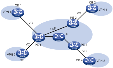
MPLS L2VPN provides Layer 2 Virtual Private Network (VPN) services on the MPLS network. It allows carriers to establish L2VPNs on different data link layer protocols, including ATM, FR, VLAN, Ethernet and PPP.
MPLS L2VPN transfers Layer 2 user data transparently on the MPLS network. For users, the MPLS network is a Layer 2 switched network and can be used to establish Layer 2 connections between nodes.
Consider ATM as an example. Each customer edge (CE) device can connect to the MPLS network through an ATM virtual circuit (VC) to communicate with another CE. This is similar to that on an ATM network.
Figure 1 Network diagram for MPLS L2VPN
Comparison with traditional VPN
Traditional VPNs based on Asynchronous Transfer Mode (ATM) or Frame Relay (FR) are quite popular. They share the network infrastructure of carriers. However, they have some inherent disadvantages:
· Dependence on dedicated media: To provide both ATM-based and FR-based VPN services, carriers must establish two separate infrastructures across the whole service scope, one ATM infrastructure and one FR infrastructure. Apparently, the cost is very high and the infrastructures are not utilized efficiently.
· Complicated deployment: To add a site to an existing VPN, you have to modify the configurations of all edge nodes connected with the VPN site.
MPLS L2VPN is developed as a solution to address the above disadvantages.
Comparison with MPLS L3VPN
Compared with MPLS L3VPN, MPLS L2VPN has the following advantages:
· High scalability. MPLS L2VPN establishes only Layer 2 connections. It does not involve the routing information for users. This greatly reduces the load of the provider edge (PE) devices and even the load of the whole service provider network, enabling carriers to support more VPNs and to service more users.
· Guaranteed reliability and private routing information security. As no routing information for users is involved, MPLS L2VPN neither tries to obtain nor processes the routing information for users, guaranteeing the security of the user VPN routing information.
· Support for multiple network layer protocols, such as IP, IPX, and SNA.
Basic concepts
In MPLS L2VPN, the concepts and principles of CE, PE and P are the same as those in MPLS L3VPN:
· Customer edge (CE) device—A CE resides on a customer network and has one or more interfaces directly connected with service provider networks. It can be a router, a switch, or a host. It cannot "sense" the existence of any VPN, neither does it need to support MPLS.
· Provider edge (PE) device—A PE resides on a service provider network and connects one or more CEs to the network. On an MPLS network, all VPN processing occurs on the PEs.
· Provider (P) device—A P device is a backbone device on a service provider network. It is not directly connected with any CE. It only needs to be equipped with basic MPLS forwarding capability.
MPLS L2VPN uses label stacks to implement the transparent transmission of user packets in the MPLS network.
· Outer label, also called tunnel label, is used to transfer packets from one PE to another.
· Inner label, also called VC label, is used to identify different connections between VPNs.
· Upon receiving packets, a PE determines to which CE the packets are to be forwarded according to the VC labels.
Figure 2 illustrates how the label stack changes in the MPLS L2VPN forwarding process.
Figure 2 MPLS L2VPN label stack processing
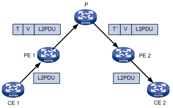
|
1) L2 PDU: Layer 2 protocol data unit |
|
2) T represents tunnel label. V represents VC label. T’ represents swapped tunnel label. |
MPLS L2VPN implementation
MPLS L2VPN can be implemented in one of the following methods:
· Circuit Cross Connect (CCC) and Static Virtual Circuit (SVC)—Two methods of implementing MPLS L2VPN by configuring VC labels statically.
· Martini—A method for establishing point-to-point links to implement MPLS L2VPN. It uses Label Distribution Protocol (LDP) as a signaling protocol to transfer VC labels.
· Kompella—A CE-to-CE mode for implementing MPLS L2VPN on the MPLS network. It uses multiprotocol BGP as the signaling protocol to advertise Layer 2 reachability information and VC labels.
The switch supports only Martini MPLS L2VPN. The following section describes the characteristics of Martini MPLS L2VPN.
Martini MPLS L2VPN
The key of the Martini method is to set up VCs between CEs.
Martini MPLS L2VPN employs VC type and VC ID to identify a VC. The VC type indicates the encapsulation type of the VC, which can be ATM, VLAN, or PPP. The VC ID uniquely identifies the VC among the VCs of the same VC type on a PE.
The PEs connecting the two CEs of a VC exchange VC labels through LDP, and bind their respective CE by the VC ID.
Once LDP establishes an LSP between the two PEs and the label exchange and the binding to CE are finished, a VC is set up and ready to transfer Layer 2 data.
To allow the exchange of VC labels between PEs, the Martini method extended LDP by adding the forwarding equivalence class (FEC) type of VC FEC. Moreover, as the two PEs exchanging VC labels might not be connected directly, a remote LDP session must be set up to transfer the VC FEC and VC labels.
With Martini MPLS L2VPN, only PEs need to maintain a small amount of VC labels and LSP mappings and no P device contains Layer 2 VPN information. Therefore, it has high scalability. In addition, to add a new VC, you only need to configure a one-way VC for each of the PEs. Your configuration will not affect the operation of the network.
The Martini method applies to scenarios with sparse Layer 2 connections, such as a scenario with a star topology.
MPLS L2VPN configuration task list
|
Task |
Remarks |
|
Required. |
|
|
Required. |
|
|
Required. |
|
|
Optional. |
|
|
Optional. |
|
|
NOTE: After you create an MPLS L2VPN connection on a Layer 3 interface, IP related functions on the sub-interfaces of the Layer 3 interface will fail. For example, the sub-interfaces cannot receive ARP or IGMP packets; they cannot forward unicast or multicast packets. After you remove the MPLS L2VPN connection, the IP related functions on the sub-interfaces recover. |
Configuring MPLS L2VPN
You can select any of the implementation methods for MPLS L2VPN as needed. However, no matter what method you select, you must complete the following tasks:
· Configure MPLS basic capability
· Enable L2VPN
· Enable MPLS L2VPN
To configure MPLS L2VPN:
|
Step |
Command |
Remarks |
|
1. Enter system view. |
system-view |
N/A |
|
2. Configure the LSR ID. |
mpls lsr-id lsr-id |
N/A |
|
3. Configure MPLS basic capability and enter MPLS view. |
mpls |
N/A |
|
4. Return to system view. |
quit |
N/A |
|
5. Enable L2VPN and enter L2VPN view. |
l2vpn |
Disabled by default. |
|
6. Enable MPLS L2VPN. |
mpls l2vpn |
N/A Disabled by default. |
Configuring a PE-CE interface of a PE
Configuring Ethernet encapsulation for the interface
By default, a Layer 3 Ethernet interface and a Layer 3 aggregate interface uses Ethernet encapsulation. For configuration information about a Layer 3 Ethernet interface, see Interface Configuration Guide. For configuration information about a Layer 3 aggregate interface, see Layer 2—LAN Switching Configuration Guide.
Configuring VLAN encapsulation for the interface
· By default, a Layer 3 Ethernet subinterface and a Layer 3 aggregate subinterface uses VLAN encapsulation. For configuration information about a Layer 3 Ethernet subinterface, see Interface Configuration Guide. For configuration information about a Layer 3 aggregate subinterface, see Layer 2—LAN Switching Configuration Guide.
· By default, a VLAN interface uses VLAN encapsulation. The VLAN interface and the CE must belong to the same VLAN. For configuration information about VLAN interface, see Layer 2—LAN Switching Configuration Guide.
Configuring Martini MPLS L2VPN
Configuring a Martini MPLS L2VPN connection on a Layer 3 interface
Martini MPLS L2VPN uses extended LDP to transfer Layer 2 information and VC labels. To configure Martini MPLS L2VPN, you need to:
· Create a Martini MPLS L2VPN connection
After a Martini MPLS L2VPN connection is created on a Layer 3 interface, packets arriving at the interface are forwarded through the MPLS L2VPN connection.
· Configure the remote peer
In Martini MPLS L2VPN implementation, VC labels need to be exchanged between PEs. Because two PEs might not be connected to each other directly, you need to establish a remote LDP session between the two PEs, so that VC FECs and VC labels can be transferred through the session.
Configuration restrictions and guidelines
· For a Martini connection, there are two main parameters: one is the IP address of the peer PE, the other is the VC ID. The combination of the VC ID and the encapsulation type must be unique on a PE. Changing the encapsulation type might result in VC ID conflicts.
· You cannot both configure Martini MPLS L2VPN and enable MPLS on a Layer 3 interface. Otherwise, neither the MPLS service nor the MPLS L2VPN service can work correctly and you must remove both services first for further service configuration.
· If a Layer 3 Ethernet interface is bound to an L2VPN, the Layer 3 Ethernet sub-interfaces of the interface cannot be bound to L2VPN or VPLS instances any more. If a Layer 3 Ethernet sub-interface is bound to an L2VPN, the Layer 3 Ethernet interface of the sub-interface cannot be bound to L2VPN or VPLS instances any more.
· When configuring a Martini MPLS L2VPN connection on a Layer 3 Ethernet sub-interface on an Ethernet interface card, you must configure the PW encapsulation mode as VLAN. Otherwise, packets might not be forwarded correctly.
Configuration prerequisites
Before configuring Martini MPLS L2VPN, complete the following tasks:
· Configure an IGP on the PEs and P devices to ensure IP connectivity on the MPLS backbone
· Configure basic MPLS and MPLS LDP on the PEs and P devices to establish LDP LSPs
· Enable MPLS L2VPN on the PEs
· For VLAN access, configure a subinterface
To configure Martini MPLS L2VPN, you need the following data:
· Types and numbers of the interfaces connecting the CEs
· L2VPN connection’s destination address and PW ID (VC ID)
· PW class
Configuration procedure
To configure a Martini MPLS L2VPN connection on a Layer 3 interface on a PE:
|
Step |
Command |
Remarks |
|
1. Enter system view. |
system-view |
N/A |
|
2. Enter the view for the interface connecting the CE. |
interface interface-type interface-number |
The specified interface must be a Layer 3 interface. |
|
3. Create a Martini MPLS L2VPN connection on the Layer 3 interface. |
mpls l2vc destination vcid [ { control-word | ethernet | no-control-word | vlan } | tunnel-policy tunnel-policy-name ] * |
N/A |
|
4. Return to system view. |
quit |
N/A |
|
5. Configure the remote peer. |
· Method 1: · Method 2: |
Use either method. For remote peer configuration, see "Configuring basic MPLS." |
Configuring a Martini MPLS L2VPN connection based on Layer 2 Ethernet interface and VLAN
If you create a Martini MPLS L2VPN connection on a VLAN interface, all packets carrying the VLAN tag will be forwarded through the connection, regardless of the Layer 2 Ethernet ports receiving the packets. This not only wastes the Layer 2 Ethernet interface and VLAN resources, but also cannot differentiate users and services connected to different Layer 2 Ethernet interfaces.
MPLS L2VPN connections based on Layer 2 Ethernet interface and VLAN can solve the above problems. Such connections forward packets based on the inbound Layer 2 Ethernet interfaces and the VLAN tags in the packets. In other words, only packets that are received on the same Layer 2 Ethernet interface and carry the same VLAN tag are forwarded through the same MPLS L2VPN connection.
To configure a connection based on Layer 2 Ethernet interface and VLAN, you need to create a service instance on the Layer 2 Ethernet interface, configure a packet matching rule for the service instance, and create a Martini MPLS L2VPN connection. After these configurations, packets that arrive at the Layer 2 Ethernet interface and match the packet matching rule will be forwarded through the created MPLS L2VPN connection.
Configuration restrictions and guidelines
· An MPLS L2VPN connection based on Layer 2 Ethernet interface and VLAN supports only LDP signaling negotiation, that is, the Martini method.
· On the private VLAN interface bound to the Martini MPLS L2VPN, do not configure services other than MPLS L2VPN. Otherwise, the MPLS L2VPN function cannot work correctly.
· Do not enable STP, Ethernet OAM, 802.1X, GVRP, LLDP, DLDP, LACP, or other port-based protocols on a port configured with MPLS L2VPN.
· For an MPLS L2VPN connection based on Layer 2 Ethernet interface and VLAN, if the access mode of the service instance created is Ethernet, do not configure the link type of the port used by the private network as Trunk. You can add the port to the access VLAN as an Access port, or configure the port link type as Hybrid and allow packets of the access VLAN to pass through untagged.
Configuration prerequisites
Before configuring an MPLS L2VPN connection based on Layer 2 Ethernet interface and VLAN, complete the following tasks:
· Configure an IGP on the PEs and P devices to ensure IP connectivity on the MPLS backbone
· Configure basic MPLS and MPLS LDP on the PEs and P devices to establish LDP LSPs
· Enable MPLS L2VPN on the PEs
To configure an MPLS L2VPN connection based on Layer 2 Ethernet interface and VLAN, you need the following data:
· Types and numbers of the interfaces connecting the CEs
· L2VPN connection’s destination address and PW ID
· PW class
Configuration procedure
To configure an MPLS L2VPN connection based on Layer 2 Ethernet interface and VLAN on a PE:
|
Step |
Command |
Remarks |
|
1. Enter system view. |
system-view |
N/A |
|
2. Create a PW class and enter PW class view. |
pw-class pw-class-name |
Optional. By default, no PW class is created. |
|
3. Specify the PW transport mode. |
trans-mode { ethernet | vlan } |
Optional. VLAN by default. |
|
4. Specify the tunneling policy. |
pw-tunnel-policy policy-name |
Optional. By default, the default tunneling policy is used. The default tunneling policy selects only one tunnel in this order: LSP tunnel, CR-LSP tunnel. For information about configuring a tunneling policy, see "Configuring MPLS L3VPN." |
|
5. Return to system view. |
quit |
N/A |
|
6. Configure the remote peer. |
· Method 1: · Method 2: |
N/A |
|
7. Enter the view of the interface connecting the CE. |
interface interface-type interface-number |
N/A |
|
8. Create a service instance and enter service instance view. |
service-instance service-instance-id |
By default, no service instance is created. |
|
9. Configure a packet matching rule for the service instance. |
encapsulation { s-vid vlan-id [ only-tagged ] | port-based | tagged | untagged } |
By default, no packet matching rule is configured for a service instance. For this configuration task, do not specify the only-tagged, port-based, tagged, and untagged keywords. Otherwise, the packet matching rule configuration will not take effect. |
|
10. Create a Martini MPLS L2VPN connection based on Layer 2 Ethernet interface and VLAN. |
xconnect peer peer-ip-address pw-id pw-id [ access-mode { ethernet | vlan } | mtu mtu-value | [ pw-class class-name ] ] * |
After this command is executed, the VLAN ID, access mode, and MTU configured for the service instance cannot be changed. To modify these parameters, you need to use the undo xconnect peer command to remove the L2VPN connection first. This command is available for service instances with the ID in the range of 1 to 4094. |
|
11. Display information about one or all service instances configured on the interface. |
display service-instance interface interface-type interface-number [ service-instance instance-id ] [ | { begin | exclude | include } regular-expression ] |
Available in any view. |
|
|
NOTE: Up to 4094 service instances can be configured on a Layer 2 Ethernet interface. |
Configuring traffic policing for an AC
Traffic policing limits the packet transmit rate to avoid network congestion.
A PE uses an attachment circuit (AC) interface to connect to a CE. To perform traffic policing for an AC:
· If the AC interface is a Layer 3 interface, configure QoS on the Layer 3 interface then create a Martini MPLS L2VPN connection on the interface.
· If the AC interface is a Layer 2 interface, create a service instance on the interface, apply global committed access rate (CAR) actions for the service instance, and then create a Martini MPLS L2VPN connection for the service instance.
This configuration task describes how to apply a global CAR action for a service instance.
Configuration prerequisites
Use the qos car command in system view to configure a global CAR action. For more information about CAR, see ACL and QoS Configuration Guide.
Configuration procedure
After you apply a global CAR action in service instance view, the device polices the inbound or outbound traffic matching the service instance according to the applied global CAR action.
To apply a global CAR action for a service instance:
|
Step |
Command |
Remarks |
|
1. Enter system view. |
system-view |
N/A |
|
2. Enter the view of the Layer 2 Ethernet interface connected to the CE. |
interface interface-type interface-number |
N/A |
|
3. Enter service instance view. |
service-instance instance-id |
N/A |
|
4. Apply a global CAR action to the inbound or outbound traffic on the AC. |
car { inbound | outbound } name car-name |
By default, no global CAR is applied to an AC. |
|
|
NOTE: To configure traffic policing for an AC, you must first configure this task before you create a Martini MPLS L2VPN connection. |
Inspecting VCs
On an MPLS L2VPN network, you can use the MPLS LSP ping function to check the VC connectivity and get necessary information for troubleshooting VC failures
On the local PE, the MPLS LSP ping function adds the label of the VC to be inspected into MPLS Echo Request messages so that the messages will travel along the VC. The local PE determines whether the VC is valid and reachable according to the replies received from the peer PE.
To check VC connectivity:
|
Task |
Command |
Remarks |
|
Use MPLS LSP ping to check the connectivity of a VC. |
ping lsp [ -a source-ip | -c count | -exp exp-value | -h ttl-value | -m wait-time | -r reply-mode | -s packet-size | -t time-out | -v ] * pw ip-address pw-id pw-id |
Available in any view. |
|
|
NOTE: · To use an S9500E switch to check the reachability of the VC to a peer PE, make sure that the peer PE supports VC inspection. The peer PE, however, cannot use this function to check the reachability of the VC to the S9500E switch. · You can use MPLS LSP ping to check the connectivity only for Martini VCs. |
Enabling the MPLS L2VPN mix function
If you configure MPLS L2VPN on both the Ethernet interface card and the base card of the switch, you need to enable the MPLS L2VPN mix function, so that the two cards can work together to forward MPLS L2VPN traffic correctly.
The MPLS L2VPN mix function and the HoVPN function are mutually exclusive. When both the Ethernet interface card and the base card of a switch are working, if you want to configure the HoVPN function on the switch, first use the undo vpn l2vpn mix command to disable the MPLS L2VPN mix function.
For more information about HoVPN, see "Configuring MPLS L3VPN." For information about Ethernet interface card and base card models, see the appendix in the switch installation guide.
To configure the MPLS L2VPN mix function:
|
Step |
Command |
Remarks |
|
1. Enter system view. |
system-view |
N/A |
|
2. Configure the system operating mode. |
system working mode { { advance | bridgee | routee } hybrid } |
The switch supports this function only when it operates in advance hybrid mode, bridgee hybrid mode, or routee hybrid mode. |
|
3. Enable the MPLS L2VPN mix function. |
vpn l2vpn mix |
Optional. Enabled by default. |
Displaying and maintaining MPLS L2VPN
|
Task |
Command |
Remarks |
|
Display information about specified L2VPN VC interfaces. |
display l2vpn ccc-interface vc-type { all | bgp-vc | ccc | ldp-vc | static-vc } [ up | down ] [ | { begin | exclude | include } regular-expression ] |
Available in any view. |
|
Display information about Martini VCs configured on the switch. |
display mpls l2vc [ interface interface-type interface-number [ service-instance instance-id ] | remote-info] [ | { begin | exclude | include } regular-expression ] |
Available in any view. |
|
Display MPLS L2VPN AC information on a switch running in standalone mode. |
display mpls l2vpn fib ac vpws [ interface interface-type interface-number [ service-instance service-instanceid ] ] [ slot slot-number ] [ | { begin | exclude | include } regular-expression ] |
Available in any view. |
|
Display MPLS L2VPN AC information on a switch running in IRF mode. |
display mpls l2vpn fib ac vpws [ interface interface-type interface-number [ service-instance service-instanceid ] ] [ chassis chassis-number slot slot-number ] [ | { begin | exclude | include } regular-expression ] |
Available in any view. |
|
Display MPLS L2VPN PW information on a switch running in standalone mode. |
display mpls l2vpn fib pw vpws [ interface interface-type interface-number [ service-instance service-instanceid ] ] [ slot slot-number ] [ verbose ] [ | { begin | exclude | include } regular-expression ] |
Available in any view. |
|
Display MPLS L2VPN PW information on a switch running in IRF mode. |
display mpls l2vpn fib pw vpws [ interface interface-type interface-number [ service-instance service-instanceid ] ] [ chassis chassis-number slot slot-number ] [ verbose ] [ | { begin | exclude | include } regular-expression ] |
Available in any view. |
|
Display information about one or all PW classes. |
display pw-class [ pw-class-name ] [ | { begin | exclude | include } regular-expression ] |
Available in any view. |
|
Clear traffic statistics for a service instance on an interface. |
reset service-instance statistics [ interface interface-type interface-number [ service-instance instance-id [ inbound | outbound ] ] ] |
Available in user view. |
MPLS L2VPN configuration example
|
|
IMPORTANT: By default, Ethernet, VLAN, and aggregate interfaces are down. To configure such an interface, bring the interface up by executing the undo shutdown command. |
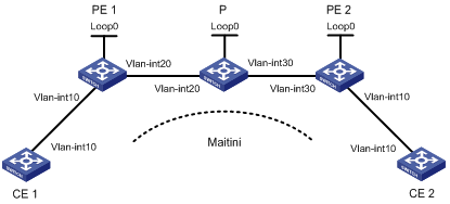
Configuring a Martini MPLS L2VPN connection based on Layer 2 Ethernet interface and VLAN
Network requirements
CEs are connected to PEs through VLAN interfaces.
Establish a Martini MPLS L2VPN connection between CE 1 and CE 2.
Figure 3 Network diagram
|
Interface |
IP address |
Device |
Interface |
IP address |
|
|
CE 1 |
Vlan-int10 |
100.1.1.1/24 |
P |
Loop0 |
192.4.4.4/32 |
|
PE 1 |
Loop0 |
192.2.2.2/32 |
|
Vlan-int20 |
10.1.1.2/24 |
|
|
Vlan-int20 |
10.1.1.1/24 |
|
Vlan-int30 |
10.2.2.2/24 |
|
CE 2 |
Vlan-int10 |
100.1.1.2/24 |
PE 2 |
Loop0 |
192.3.3.3/32 |
|
|
|
|
|
Vlan-int30 |
10.2.2.1/24 |
Configuration procedure
1. Configure CE 1.
<Sysname> system-view
[Sysname] sysname CE1
[CE1] interface vlan-interface 10
[CE1-Vlan-interface10] ip address 100.1.1.1 24
2. Configure PE 1:
# Configure the LSR ID and enable MPLS globally.
<Sysname> system-view
[Sysname] sysname PE1
[PE1] interface loopback 0
[PE1-LoopBack0] ip address 192.2.2.2 32
[PE1-LoopBack0] quit
[PE1] mpls lsr-id 192.2.2.2
[PE1] mpls
[PE1-mpls] quit
# Enable L2VPN and MPLS L2VPN.
[PE1] l2vpn
[PE1-l2vpn] mpls l2vpn
[PE1-l2vpn] quit
# Enable LDP globally.
[PE1] mpls ldp
[PE1-mpls-ldp] quit
# Establish an LDP remote session with PE 2.
[PE1] mpls ldp remote-peer 1
[PE1-mpls-ldp-remote-1] remote-ip 192.3.3.3
[PE1-mpls-ldp-remote-1] quit
# Configure the interface connected with the P switch and enable LDP on the interface.
[PE1] interface vlan-interface 20
[PE1-Vlan-interface20] ip address 10.1.1.1 24
[PE1-Vlan-interface20] mpls
[PE1-Vlan-interface20] mpls ldp
[PE1-Vlan-interface20] quit
# Configure OSPF.
[PE1] ospf
[PE1-ospf-1] area 0
[PE1-ospf-1-area-0.0.0.0] network 10.1.1.1 0.0.0.255
[PE1-ospf-1-area-0.0.0.0] network 192.2.2.2 0.0.0.0
[PE1-ospf-1-area-0.0.0.0] quit
[PE1-ospf-1] quit
# Create a service instance and then an MPLS L2VPN connection on GigabitEthernet 3/0/1, the interface connected to CE 1.
[PE1] interface GigabitEthernet 3/0/1
[PE1-GigabitEthernet3/0/1] port access vlan 10
[PE1-GigabitEthernet3/0/1] service-instance 1000
[PE1-GigabitEthernet3/0/1-srv1000] encapsulation s-vid 10
[PE1-GigabitEthernet3/0/1-srv1000] xconnect peer 192.3.3.3 pw-id 1000
[PE1-GigabitEthernet3/0/1-srv1000] quit
[PE1-GigabitEthernet3/0/1] quit
3. Configure the P switch:
# Configure the LSR ID and enable MPLS globally.
<Sysname> system-view
[Sysname] sysname P
[P] interface loopback 0
[P-LoopBack0] ip address 192.4.4.4 32
[P-LoopBack0] quit
[P] mpls lsr-id 192.4.4.4
[P] mpls
[P-mpls] quit
# Enable LDP globally.
[P] mpls ldp
[P-mpls-ldp] quit
# Configure the interface connected with PE 1 and enable LDP on the interface.
[P] interface vlan-interface 20
[P-Vlan-interface20] ip address 10.1.1.2 24
[P-Vlan-interface20] mpls
[P-Vlan-interface20] mpls ldp
[P-Vlan-interface20] quit
# Configure the interface connected with PE 2 and enable LDP on the interface.
[P] interface vlan-interface 30
[P-Vlan-interface30] ip address 10.2.2.2 24
[P-Vlan-interface30] mpls
[P-Vlan-interface30] mpls ldp
[P-Vlan-interface30] quit
# Configure OSPF.
[P] ospf
[P-ospf-1] area 0
[P-ospf-1-area-0.0.0.0] network 10.1.1.2 0.0.0.255
[P-ospf-1-area-0.0.0.0] network 10.2.2.2 0.0.0.255
[P-ospf-1-area-0.0.0.0] network 192.4.4.4 0.0.0.0
[P-ospf-1-area-0.0.0.0] quit
[P-ospf-1] quit
4. Configure PE 2:
# Configure the LSR ID and enable MPLS globally.
<Sysname> system-view
[Sysname] sysname PE2
[PE2] interface loopback 0
[PE2-LoopBack0] ip address 192.3.3.3 32
[PE2-LoopBack0] quit
[PE2] mpls lsr-id 192.3.3.3
[PE2] mpls
[PE2-mpls] quit
# Enable L2VPN and MPLS L2VPN.
[PE2] l2vpn
[PE2-l2vpn] mpls l2vpn
[PE2-l2vpn] quit
# Enable LDP globally.
[PE2] mpls ldp
[PE2-mpls-ldp] quit
# Establish a remote LDP connection with PE 1.
[PE2] mpls ldp remote-peer 2
[PE2-mpls-ldp-remote-2] remote-ip 192.2.2.2
[PE2-mpls-ldp-remote-2] quit
# Configure the interface connected to the P switch and enable LDP on the interface.
[PE2] interface vlan-interface 30
[PE2-Vlan-interface30] ip address 10.2.2.1 24
[PE2-Vlan-interface30] mpls
[PE2-Vlan-interface30] mpls ldp
[PE2-Vlan-interface30] quit
# Configure OSPF.
[PE2] ospf
[PE2-ospf-1] area 0
[PE2-ospf-1-area-0.0.0.0] network 192.3.3.3 0.0.0.0
[PE2-ospf-1-area-0.0.0.0] network 10.2.2.0 0.0.0.255
[PE2-ospf-1-area-0.0.0.0] quit
[PE2-ospf-1] quit
# Create a service instance and then an MPLS L2VPN connection on GigabitEthernet 3/0/1, the interface connected to CE 2.
[PE2] interface GigabitEthernet 3/0/1
[PE2-GigabitEthernet3/0/1] port access vlan 10
[PE2-GigabitEthernet3/0/1] service-instance 1000
[PE2-GigabitEthernet3/0/1-srv1000] encapsulation s-vid 10
[PE2-GigabitEthernet3/0/1-srv1000] xconnect peer 192.2.2.2 pw-id 1000
[PE2-GigabitEthernet3/0/1-srv1000] quit
[PE2-GigabitEthernet3/0/1] quit
5. Configure CE 2.
<Sysname> system-view
[Sysname] sysname CE2
[CE2] interface vlan-interface 10
[CE2-Vlan-interface10] ip address 100.1.1.2 24
6. Verify your configuration:
# Display L2VPN connection information on PE 1. The output shows that an L2VC has been established.
[PE1] display mpls l2vc
Total ldp vc : 1 1 up 0 down
Transport Client VC Local Remote
VC ID Intf State VC Label VC Label
1000 Vlan10 up 8193 8192
# Display L2VPN connection information on PE 2. The output shows that an L2VC has been established.
[PE2] display mpls l2vc
Total ldp vc : 1 1 up 0 down
Transport Client VC Local Remote
VC ID Intf State VC Label VC Label
1000 Vlan10 up 8192 8193
# Verify that CE 1 can ping CE 2.
[CE1] ping 100.1.1.2
PING 100.1.1.2: 56 data bytes, press CTRL_C to break
Reply from 100.1.1.2: bytes=56 Sequence=1 ttl=255 time=90 ms
Reply from 100.1.1.2: bytes=56 Sequence=2 ttl=255 time=77 ms
Reply from 100.1.1.2: bytes=56 Sequence=3 ttl=255 time=34 ms
Reply from 100.1.1.2: bytes=56 Sequence=4 ttl=255 time=46 ms
Reply from 100.1.1.2: bytes=56 Sequence=5 ttl=255 time=94 ms
--- 100.1.1.2 ping statistics ---
5 packet(s) transmitted
5 packet(s) received
0.00% packet loss
round-trip min/avg/max = 34/68/94 ms
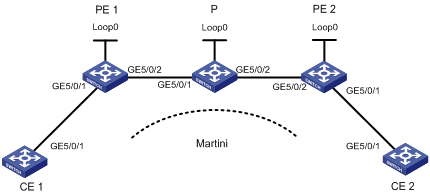
Configuring a Martini MPLS L2VPN on a Layer 3 Ethernet interface
Network requirements
CEs are connected to PEs through routing interfaces.
Establish a Martini MPLS L2VPN between CE 1 and CE 2.
Figure 4 Network diagram
|
Interface |
IP address |
Device |
Interface |
IP address |
|
|
CE 1 |
GE5/0/1 |
100.1.1.1/24 |
P |
Loop0 |
192.4.4.4/32 |
|
PE 1 |
Loop0 |
192.2.2.2/32 |
|
GE5/0/1 |
10.1.1.2/24 |
|
|
GE5/0/2 |
10.1.1.1/24 |
|
GE5/0/2 |
10.2.2.2/24 |
|
CE 2 |
GE5/0/1 |
100.1.1.2/24 |
PE 2 |
Loop0 |
192.3.3.3/32 |
|
|
|
|
|
GE5/0/2 |
10.2.2.1/24 |
Configuration procedure
1. Configure CE 1.
<Sysname> system-view
[Sysname] sysname CE1
[CE1] interface GigabitEthernet 5/0/1
[CE1-GigabitEthernet5/0/1] port link-mode route
[CE1-GigabitEthernet5/0/1] ip address 100.1.1.1 24
2. Configure PE 1:
# Configure the LSR ID and enable MPLS globally.
<Sysname> system-view
[Sysname] sysname PE1
[PE1] interface loopback 0
[PE1-LoopBack0] ip address 192.2.2.2 32
[PE1-LoopBack0] quit
[PE1] mpls lsr-id 192.2.2.2
[PE1] mpls
# Enable L2VPN and MPLS L2VPN.
[PE1] l2vpn
[PE1-l2vpn] mpls l2vpn
[PE1-l2vpn] quit
# Enable LDP globally.
[PE1] mpls ldp
[PE1-mpls-ldp] quit
# Configure the peer relationship with PE 2 so that the LDP remote session can be established between them.
[PE1] mpls ldp remote-peer 1
[PE1-mpls-ldp-remote-1] remote-ip 192.3.3.3
[PE1-mpls-ldp-remote-1] quit
# Configure the interface connected with the P device (GigabitEthernet 5/0/2), and enable LDP on the interface.
[PE1] interface GigabitEthernet 5/0/2
[PE1-GigabitEthernet5/0/2] port link-mode route
[PE1-GigabitEthernet5/0/2] ip address 10.1.1.1 24
[PE1-GigabitEthernet5/0/2] mpls
[PE1-GigabitEthernet5/0/2] mpls ldp
[PE1-GigabitEthernet5/0/2] quit
# Configure OSPF on PE 1 for establishing LSPs.
[PE1] ospf
[PE1-ospf-1] area 0
[PE1-ospf-1-area-0.0.0.0] network 10.1.1.1 0.0.0.255
[PE1-ospf-1-area-0.0.0.0] network 192.2.2.2 0.0.0.0
[PE1-ospf-1-area-0.0.0.0] quit
[PE1-ospf-1] quit
# On the interface connected to CE 1 (GigabitEthernet 5/0/1), create a Martini MPLS L2VPN connection. The interface requires no IP address.
[PE1] interface GigabitEthernet 5/0/1
[PE1-GigabitEthernet5/0/1] port link-mode route
[PE1-GigabitEthernet5/0/1] mpls l2vc 192.3.3.3 101
[PE1-GigabitEthernet5/0/1] quit
3. Configure the P device:
# Configure the LSR ID and enable MPLS globally.
<Sysname> system-view
[Sysname] sysname P
[P] interface loopback 0
[P-LoopBack0] ip address 192.4.4.4 32
[P-LoopBack0] quit
[P] mpls lsr-id 192.4.4.4
[P] mpls
# Enable LDP globally.
[P] mpls ldp
[P-mpls-ldp] quit
# Configure the interface connected with PE 1 (GigabitEthernet 5/0/1), and enable LDP on the interface.
[P] interface GigabitEthernet 5/0/1
[P-GigabitEthernet5/0/1] port link-mode route
[P-GigabitEthernet5/0/1] ip address 10.1.1.2 24
[P-GigabitEthernet5/0/1] mpls
[P-GigabitEthernet5/0/1] mpls ldp
[P-GigabitEthernet5/0/1] quit
# Configure the interface connected with PE 2 (GigabitEthernet 5/0/2), and enable LDP on the interface.
[P] interface GigabitEthernet 5/0/2
[P-GigabitEthernet5/0/2] port link-mode route
[P-GigabitEthernet5/0/2] ip address 10.2.2.2 24
[P-GigabitEthernet5/0/2] mpls
[P-GigabitEthernet5/0/2] mpls ldp
[P-GigabitEthernet5/0/2] quit
# Configure OSPF on the P device for establishing LSPs.
[P] ospf
[P-ospf-1] area 0
[P-ospf-1-area-0.0.0.0] network 10.1.1.2 0.0.0.255
[P-ospf-1-area-0.0.0.0] network 10.2.2.2 0.0.0.255
[P-ospf-1-area-0.0.0.0] network 192.4.4.4 0.0.0.0
[P-ospf-1-area-0.0.0.0] quit
[P-ospf-1] quit
4. Configure PE 2:
# Configure the LSR ID and enable MPLS globally.
<Sysname> system-view
[Sysname] sysname PE2
[PE2] interface loopback 0
[PE2-LoopBack0] ip address 192.3.3.3 32
[PE2-LoopBack0] quit
[PE2] mpls lsr-id 192.3.3.3
[PE2] mpls
# Enable L2VPN and MPLS L2VPN.
[PE2] l2vpn
[PE2-l2vpn] mpls l2vpn
[PE2-l2vpn] quit
# Enable LDP globally.
[PE2] mpls ldp
[PE2-mpls-ldp] quit
# Configure the peer relationship with PE 1 so that the LDP remote session can be established between them.
[PE2] mpls ldp remote-peer 2
[PE2-mpls-ldp-remote-2] remote-ip 192.2.2.2
[PE2-mpls-ldp-remote-2] quit
# Configure the interface connected with the P device (GigabitEthernet 5/0/2), and enable LDP on the interface.
[PE2] interface GigabitEthernet 5/0/2
[PE2-GigabitEthernet5/0/2] port link-mode route
[PE2-GigabitEthernet5/0/2] ip address 10.2.2.1 24
[PE2-GigabitEthernet5/0/2] mpls
[PE2-GigabitEthernet5/0/2] mpls ldp
[PE2-GigabitEthernet5/0/2] quit
# Configure OSPF on PE 2 for establishing LSPs.
[PE2] ospf
[PE2-ospf-1] area 0
[PE2-ospf-1-area-0.0.0.0] network 192.3.3.3 0.0.0.0
[PE2-ospf-1-area-0.0.0.0] network 10.2.2.0 0.0.0.255
[PE2-ospf-1-area-0.0.0.0] quit
[PE2-ospf-1] quit
# On the interface connected to CE 2 (GigabitEthernet 5/0/1), create a Martini MPLS L2VPN connection. The interface requires no IP address.
[PE2] interface GigabitEthernet 5/0/1
[PE2-GigabitEthernet5/0/1] port link-mode route
[PE2-GigabitEthernet5/0/1] mpls l2vc 192.2.2.2 101
[PE2-GigabitEthernet5/0/1] quit
5. Configure CE 2.
<Sysname> system-view
[Sysname] sysname CE2
[CE2] interface GigabitEthernet 5/0/1
[CE2-GigabitEthernet5/0/1] port link-mode route
[CE2-GigabitEthernet5/0/1] ip address 100.1.1.2 24
6. Verify your configuration:
# Display L2VPN connection information on PE 1. The output shows that an L2VC has been established.
[PE1] display mpls l2vc
Total ldp vc : 1 1 up 0 down 0 blocked
Transport Client Service VC Local Remote
VC ID Intf ID State VC Label VC Label
101 GE5/0/1 -- up 65880 65674
# Display L2VPN connection information on PE 2. The output shows that an L2VC has been established.
[PE2] display mpls l2vc
Total ldp vc : 1 1 up 0 down 0 blocked
Transport Client Service VC Local Remote
VC ID Intf ID State VC Label VC Label
101 GE5/0/1 -- up 65674 65880
# Verify that CE 1 can ping CE 2.
[CE1] ping 100.1.1.2
PING 100.1.1.2: 56 data bytes, press CTRL_C to break
Reply from 100.1.1.2: bytes=56 Sequence=1 ttl=255 time=30 ms
Reply from 100.1.1.2: bytes=56 Sequence=2 ttl=255 time=60 ms
Reply from 100.1.1.2: bytes=56 Sequence=3 ttl=255 time=50 ms
Reply from 100.1.1.2: bytes=56 Sequence=4 ttl=255 time=40 ms
Reply from 100.1.1.2: bytes=56 Sequence=5 ttl=255 time=70 ms
--- 100.1.1.2 ping statistics ---
5 packet(s) transmitted
5 packet(s) received
0.00% packet loss
round-trip min/avg/max = 30/50/70 ms
Troubleshooting MPLS L2VPN
Symptom 1
After the L2VPN configuration, the peer PEs cannot ping each other. The display mpls l2vc command output shows that the VC is down and the remote VC label is invalid (displayed as two hyphens --).
Analysis
The reason the VC is down might be that the PEs are configured with different encapsulation types.
Solution
1. Check whether the local PE and the peer PE are configured with the same encapsulation type. If not, the connection is destined to fail.
2. Verify that the PEs are configured with the Remote argument and that the peer addresses are correctly configured.
Symptom 2
POS 2/1/1 uses HDLC encapsulation and POS 2/1/2 uses PPP encapsulation. They each create an LDP connection, with the same VC ID of 1. If you change the encapsulation type of POS 2/1/2 to HDLC, the expected LDP connection cannot be established.
Analysis
When you change the encapsulation type of POS 2/1/2 to HDLC, another LDP connection is established, with the same encapsulation type of HDLC and the same VC ID of 1. To avoid VC ID conflict, the system removes the new LDP connection automatically.
Solution
Configure different VC IDs for the two interfaces.