- Table of Contents
- Related Documents
-
| Title | Size | Download |
|---|---|---|
| 03-Multicast routing and forwarding configuration | 285.28 KB |
Contents
Configuring multicast routing and forwarding
Multicast forwarding across unicast subnets
Configuring multicast routing and forwarding
Configuring static multicast routes
Configuring the RPF route selection rule
Configuring multicast load splitting
Configuring a multicast forwarding boundary
Configuring static multicast MAC address entries
Configuring RPF check failure processing
Displaying and maintaining multicast routing and forwarding
Multicast forwarding over a GRE tunnel
Troubleshooting multicast routing and forwarding
Static multicast route failure
Overview
The following tables are involved in multicast routing and forwarding:
· Multicast routing table of each multicast routing protocol, such as the PIM routing table.
· General multicast routing table that summarizes the multicast routing information of different multicast routing protocols. This general multicast routing table consists of a set of (S, G) entries. Each entry contains the multicast routing information for delivering multicast data from a multicast source (S) to a multicast group (G).
· Multicast forwarding table that guides multicast forwarding. The router chooses an optimal route from the multicast routing table and installs this route entry into its multicast forwarding table.
The switch operates in IRF or standalone (the default) mode. For more information about the IRF mode, see IRF Configuration Guide.
RPF check mechanism
A multicast routing protocol uses reverse path forwarding (RPF) check to ensure the multicast data delivery along the correct paths when the multicast routing protocol creates multicast routing entries based on the existing unicast routes, MBGP routes, or static multicast routes. RPF check also helps avoid data loops.
A multicast routing protocol uses the following tables to perform an RPF check:
· Unicast routing table—Contains unicast routing information.
· MBGP multicast routing table—Contains MBGP multicast routing information.
· Static multicast routing table—Contains RPF routes that are manually configured.
MBGP multicast routing table and static multicast routing table are used for RPF check rather than multicast routing.
RPF check process
When performing an RPF check, the router searches its unicast routing table, MBGP routing table, and static multicast routing table at the same time using the following process:
1. The router separately chooses an optimal route from the unicast routing table, MBGP routing table, and the static multicast routing table:
¡ The router looks up its unicast routing table by using the IP address of the packet source as the destination address, and automatically chooses an optimal unicast route. The outgoing interface of the route is the RPF interface and the next hop is the RPF neighbor. The router considers the path of the packet that the RPF interface receives from the RPF neighbor as the shortest path that leads back to the source.
¡ The router looks up its MBGP routing table by using the IP address of the packet source as the destination address, and automatically chooses an optimal MBGP route. The outgoing interface of the route is the RPF interface and the next hop is the RPF neighbor.
¡ The router looks up its static multicast routing table by using the IP address of the packet source as the source address, and automatically chooses an optimal static multicast route. The route explicitly defines the RPF interface and the RPF neighbor.
2. The router selects one of the three optimal routes as the RPF route according to the following principles:
¡ If the router uses the longest prefix match principle, it selects the matching route as the RPF route. If the routes have the same mask, the router selects the route that has the highest priority as the RPF route. If the routes have the same priority, the router selects a route as the RPF route in the order of static multicast route, MBGP route, and unicast route.
For more information about the route preference, see Layer 3—IP Routing Configuration Guide.
¡ If the router does not use the longest prefix match principle, it selects the route that has the highest priority as the RPF route. If the routes have the same priority, the router selects a route as the RPF route in the order of static multicast route, MBGP route, and unicast route.
In RPF checks, a "packet source" means different things in different situations:
· For a packet that travels along the SPT from the multicast source to the receivers or to the RP, the packet source is the multicast source.
· For a packet that travels along the RPT from the RP to the receivers, or along the source-side RPT from the multicast source to the RP, the packet source is the RP.
· For a bootstrap message from the BSR, the packet source is the BSR.
For more information about the concepts of SPT, RPT, source-side RPT, RP, and BSR, see "Configuring PIM."
RPF check implementation in multicast
Implementing an RPF check on each received multicast packet brings a big burden to the router. The use of a multicast forwarding table is the solution to this issue. When the router creates a multicast routing entry and a multicast forwarding entry for a multicast packet, it sets the RPF interface of the packet as the incoming interface of the forwarding entry. After the router receives a multicast packet, it looks up its multicast forwarding table:
· If no forwarding entry matches the packet, the packet undergoes an RPF check. The router creates a multicast routing entry with the RPF interface as the incoming interface and adds the entry into the multicast forwarding table. The process goes as follows:
¡ If the interface that received the packet is the RPF interface, the RPF check succeeds and the router forwards the packet out of all the outgoing interfaces.
¡ If the interface that received the packet is not the RPF interface, the RPF check fails and the router discards the packet.
· If a forwarding entry matches the packet and the interface that received the packet is the incoming interface of the forwarding entry, the router forwards the packet out of all the outgoing interfaces.
· If a forwarding entry matches the packet but the interface that received the packet is not the incoming interface of the forwarding entry, the multicast packet undergoes an RPF check.
¡ If the RPF interface is the incoming interface, it indicates that the forwarding entry is correct, but the packet traveled along a wrong path. The router discards the packet.
¡ If the RPF interface is not the incoming interface, it indicates that the forwarding entry has expired, and the router replaces the incoming interface with the RPF interface. In this case, if the interface that received the packet is the RPF interface, the router forwards the packet out of all outgoing interfaces. Otherwise, it discards the packet.
|
|
NOTE: You can configure special processing of packets that have failed an RPF check so they will not be simply dropped. For more information, see "Configuring RPF check failure processing." |
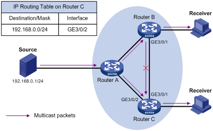
As shown in Figure 1, assume that unicast routes are available in the network, MBGP is not configured, and no static multicast routes have been configured on Router C. Multicast packets travel along the SPT from the multicast source to the receivers. The multicast forwarding table on Router C contains the (S, G) entry, with GigabitEthernet 3/0/2 as the incoming interface.
· When GigabitEthernet 3/0/2 of Router C receives a multicast packet, because the interface is the incoming interface of the (S, G) entry, the router forwards the packet out of all outgoing interfaces.
· When GigabitEthernet 3/0/1 of Router C receives a multicast packet, because the interface is not the incoming interface of the (S, G) entry, the router performs an RPF check on the packet. The router looks up its unicast routing table and finds that the outgoing interface to the source (the RPF interface) is Ethernet GigabitEthernet 3/0/2. It indicates that the (S, G) entry is correct, but the packet traveled along a wrong path. The RPF check fails and the router discards the packet.
Static multicast routes
Depending on the application environment, a static multicast route can change an RPF route or create an RPF route.
Changing an RPF route
Typically, the topology structure of a multicast network is the same as that of a unicast network, and multicast traffic follows the same transmission path as unicast traffic does. You can configure a static multicast route for a given multicast source to change the RPF route, so that the router creates a transmission path for multicast traffic that is different from the transmission path for unicast traffic.
Figure 2 Changing an RPF route
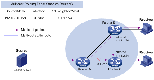
As shown in Figure 2, when no static multicast route is configured, Router C's RPF neighbor on the path back to the source is Router A, and the multicast data from the source travels through Router A to Router C. When a static multicast route is configured on Router C with Router B as its RPF neighbor on the path back to the source, the multicast data from the source travels along the path: Router A to Router B and then to Router C.
Creating an RPF route
When a unicast route is blocked, multicast forwarding might be stopped due to lack of an RPF route. In this case, you can create an RPF route by configuring a static multicast route for a given multicast source, so that a multicast routing entry is created to guide multicast forwarding.
Figure 3 Creating an RPF route
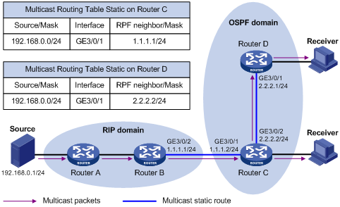
As shown in Figure 3, the RIP domain and the OSPF domain are unicast isolated from each other. When no static multicast route is configured, the receiver hosts in the OSPF domain cannot receive the multicast packets from the multicast source in the RIP domain. If you configure a static multicast route on Router C and Router D, specifying Router B as the RPF neighbor of Router C and Router C as the RPF neighbor of Router D, the receiver hosts can receive the multicast data from the multicast source.
|
|
NOTE: A static multicast route is effective only on the multicast router on which it is configured, and will not be advertised throughout the network or redistributed to other routers. |
Multicast forwarding across unicast subnets
Routers forward the multicast data from a multicast source hop by hop along the forwarding tree, but some routers might not support multicast protocols in a network. When the multicast data is forwarded to a router that does not support IP multicast, the forwarding path is blocked. In this case, you can enable multicast forwarding across two unicast subnets by establishing a tunnel between the routers at the edges of the two unicast subnets.
Figure 4 Multicast data transmission through a tunnel
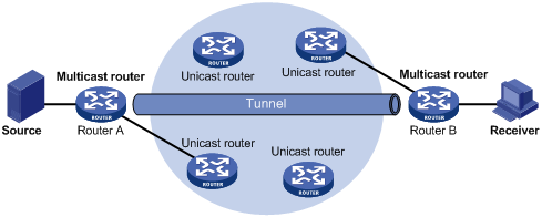
As shown in Figure 4, with a tunnel established between the multicast routers Router A and Router B, Router A encapsulates the multicast data in unicast IP packets, and forwards them to Router B across the tunnel through unicast routers. Then, Router B strips off the unicast IP header and continues to forward the multicast data to the receiver.
To use this tunnel only for multicast traffic, configure the tunnel as the outgoing interface only for multicast routes.
Configuration task list
|
Tasks at a glance |
|
(Required.) Enabling IP multicast routing |
|
(Optional.) Configuring multicast routing and forwarding · (Optional.) Configuring static multicast routes · (Optional.) Configuring the RPF route selection rule · (Optional.) Configuring multicast load splitting · (Optional.) Configuring static multicast MAC address entries · (Optional.) Configuring RPF check failure processing |
|
|
NOTE: The device can route and forward multicast data only through the primary IP addresses of interfaces, rather than their secondary addresses. For more information about primary and secondary IP addresses, see Layer 3—IP Services Configuration Guide. |
Enabling IP multicast routing
Before you configure any Layer 3 multicast functionality, you must enable IP multicast routing.
To enable IP multicast routing:
|
Step |
Command |
Remarks |
|
1. Enter system view. |
system-view |
N/A |
|
2. Enable IP multicast routing. |
multicast routing-enable |
By default, IP multicast routing is disabled. |
Configuring multicast routing and forwarding
Before you configure multicast routing and forwarding, complete the following tasks:
· Configure a unicast routing protocol so that all devices in the domain are interoperable at the network layer.
· Enable PIM-DM or PIM-SM.
Configuring static multicast routes
By configuring a static multicast route for a given multicast source, you can specify an RPF interface or an RPF neighbor for the multicast traffic from that source.
To configure a static multicast route:
|
Step |
Command |
Remarks |
|
1. Enter system view. |
system-view |
N/A |
|
2. Configure a static multicast route. |
ip rpf-route-static source-address { mask-length | mask } { rpf-nbr-address | interface-type interface-number } [ preference preference ] |
By default, no static multicast route is configured. |
|
3. (Optional.) Delete static multicast routes. |
·
Delete a specified static multicast route: · Delete all static multicast routes: |
N/A |
Configuring the RPF route selection rule
You can configure the router to select the RPF route based on the longest prefix match principle. For more information about RPF route selection, see "RPF check process."
To configure a multicast routing policy:
|
Step |
Command |
Remarks |
|
1. Enter system view. |
system-view |
N/A |
|
2. Configure the device to select the RPF route based on the longest prefix match. |
multicast longest-match |
By default, the route with the highest priority is selected as the RPF route. |
Configuring multicast load splitting
To optimize the traffic delivery for multiple data flows, you can configure load sharing on a per-source basis or on a per-source-and-group basis.
To configure multicast load splitting:
|
Step |
Command |
Remarks |
|
1. Enter system view. |
system-view |
N/A |
|
2. Configure multicast load splitting. |
multicast load-splitting { source | source-group } |
By default, load splitting is disabled. |
Configuring a multicast forwarding boundary
A multicast forwarding boundary sets the boundary condition for the multicast groups in a specified range. The multicast data for a multicast group travels within a definite boundary in a network. If the destination address of a multicast packet matches the boundary condition, the packet is not forwarded. If an interface is configured as a multicast boundary, it can no longer forward multicast packets (including packets sent from the local device), nor receive multicast packets.
To configure a multicast forwarding boundary:
|
Step |
Command |
Remarks |
|
1. Enter system view. |
system-view |
N/A |
|
2. Enter interface view. |
interface interface-type interface-number |
N/A |
|
3. Configure a multicast forwarding boundary. |
multicast boundary group-address { mask-length | mask } |
By default, no forwarding boundary is configured. |
Configuring static multicast MAC address entries
In Layer 2 multicast, multicast MAC address entries can be dynamically created or added through Layer 2 multicast protocols (such as IGMP snooping). You can also manually configure static multicast MAC address entries to bind multicast MAC addresses and ports to control the destination ports of the multicast data.
When you configure static multicast MAC address entries, follow these guidelines:
· You can configure static multicast MAC address entries on the specified interface in system view, or on the current interface in interface view.
· The multicast MAC address that can be manually configured in the multicast MAC address entry must be unused. (The least significant bit of the most significant octet is 1.)
To configure a static multicast MAC address entry in system view:
|
Step |
Command |
Remarks |
|
1. Enter system view. |
system-view |
N/A |
|
2. Configure a static multicast MAC address entry. |
mac-address multicast mac-address interface interface-list vlan vlan-id |
By default, no static multicast MAC address entries exist. |
To configure a static multicast MAC address entry in interface view:
|
Step |
Command |
Remarks |
|
1. Enter system view. |
system-view |
N/A |
|
2. Enter Ethernet interface/Layer 2 aggregate interface view. |
interface interface-type interface-number |
N/A |
|
3. Configure a static multicast MAC address entry. |
mac-address multicast mac-address vlan vlan-id |
By default, no static multicast MAC address entries exist. |
Configuring RPF check failure processing
If a multicast packet fails an RPF check, the router can process the packet using the following methods:
Enabling forwarding the packets in the VLAN
The following configuration methods are available to forward to the receivers multicast packets that have failed RPF checks on a VLAN interface:
· Configure flooding these multicast packets in all VLANs.
After this configuration, use the reset multicast forwarding-table command to clear all forwarding entries in the multicast forwarding table. Otherwise, this configuration cannot take effect.
· Configure multicasting these multicast packets in the current VLAN after you configure flooding them in all VLANs.
Before this configuration, IGMP snooping must be enabled in the VLAN and a Layer 3 multicast routing protocol (such as IGMP or PIM) on the corresponding VLAN interface must be configured. Otherwise, this configuration cannot take effect.
After this configuration, use the reset igmp-snooping group command to clear IGMP snooping forwarding entries of all dynamic multicast groups in the VLAN. Otherwise, this configuration cannot take effect. For more information about the reset igmp-snooping group command, see IP Multicast Command Reference.
After the configurations have been completed, the packets are multicast if IGMP snooping forwarding entries exist. Otherwise, they are flooded in the current VLAN.
To enable forwarding the multicast packets that have failed RPF checks:
|
Step |
Command |
Remarks |
|
1. Enter system view. |
system-view |
N/A |
|
2. Configure flooding the multicast packets that have failed RPF checks in all VLANs. |
multicast rpf-fail-pkt flooding |
By default, the multicast packets that have failed RPF checks are not flooded in the VLAN. |
|
3. Enter VLAN interface view. |
interface vlan-interface vlan-interface-id |
N/A |
|
4. Configure multicasting the multicast packets that have failed RPF checks in the current VLAN. |
multicast rpf-fail-pkt bridging |
By default, the multicast packets that have failed RPF checks are not multicast in the current VLAN. |
Delivering the packets to the CPU
In the following cases, multicast packets that have failed RPF checks must be delivered to the CPU:
· If a multicast packet arrives on an outgoing interface of the corresponding multicast forwarding entry, the packet fails the RPF check and must be delivered to CPU to trigger the assert mechanism to prune the unwanted branch.
· If the SPT and RPT have different incoming interfaces on the receiver-side DR (the last-hop router), the multicast traffic fails the RPF check on the SPT incoming interface during an RPT-to-SPT switchover before the RPF information is refreshed. If the RPT is pruned at this moment, the multicast service is instantaneously interrupted. By delivering packets that have failed RPF checks on a non-outgoing interface to the CPU, the router can check whether the packets that have failed RPF checks on the SPT interface are expected. If they are expected, the router initiates an RPT prune.
For more information about the assert mechanism, DR and RPT-to-SPT switchover, see "Configuring PIM."
After the configuration, use the reset multicast forwarding-table command to clear all forwarding entries in the multicast forwarding table. Otherwise, this configuration does not take effect.
To enable delivering packets that have failed RPF checks to the CPU:
|
Step |
Command |
Remarks |
|
1. Enter system view. |
system-view |
N/A |
|
2. Enable delivering packets that have failed RPF checks to the CPU. |
multicast rpf-fail-pkt trap-to-cpu |
By default, multicast packets that have failed RPF checks are not delivered to the CPU. |
Displaying and maintaining multicast routing and forwarding
|
|
CAUTION: The reset commands might cause multicast data transmission failures. |
Execute display commands in any view and reset command in user view.
|
Task |
Command |
|
Display information about static multicast MAC address table. |
display mac-address [ mac-address [ vlan vlan-id ] | [ multicast ] [ vlan vlan-id ] [ count ] ] |
|
Display multicast boundary information. |
display multicast boundary [ group-address [ mask-length | mask ] ] [ interface interface-type interface-number ] |
|
Display multicast forwarding table information (in standalone mode). |
display multicast forwarding-table [ source-address [ mask { mask-length | mask } ] | group-address [ mask { mask-length | mask } ] | incoming-interface interface-type interface-number | outgoing-interface { exclude | include | match } interface-type interface-number | slot slot-number | statistics ] * |
|
Display multicast forwarding table information (in IRF mode). |
display multicast forwarding-table [ source-address [ mask { mask-length | mask } ] | group-address [ mask { mask-length | mask } ] | chassis chassis-number slot slot-number | incoming-interface interface-type interface-number | outgoing-interface { exclude | include | match } interface-type interface-number | statistics ] * |
|
Display information about the multicast routing table. |
display multicast routing-table [ source-address [ mask { mask-length | mask } ] | group-address [ mask { mask-length | mask } ] | incoming-interface interface-type interface-number | outgoing-interface { exclude | include | match } interface-type interface-number ] * |
|
Display information about the static multicast routing table. |
display multicast routing-table static [ source-address { mask-length | mask } ] |
|
Display RPF route information about the multicast source. |
display multicast rpf-info source-address [ group-address ] |
|
Clear forwarding entries from the multicast forwarding table. |
reset multicast forwarding-table { { source-address [ mask { mask-length | mask } ] | group-address [ mask { mask-length | mask } ] | incoming-interface { interface-type interface-number } } * | all } |
|
Clear routing entries from the multicast routing table. |
reset multicast routing-table { { source-address [ mask { mask-length | mask } ] | group-address [ mask { mask-length | mask } ] | incoming-interface interface-type interface-number } * | all } |
|
|
NOTE: When a routing entry is removed, the associated forwarding entry is also removed. When a forwarding entry is removed, the associated routing entry is also removed. |
Configuration examples
|
|
IMPORTANT: By default, Ethernet interfaces, VLAN interfaces, and aggregate interfaces are in the state of DOWN. To configure such an interface, use the undo shutdown command to bring it up first. |
Changing an RPF route
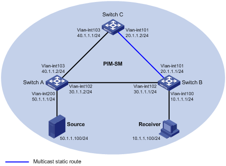
Network requirements
PIM-SM runs in the network. All switches in the network support multicast. Switch A, Switch B and Switch C run OSPF. Switch A acts as the C-BSR and the C-RP. Typically, the receiver host can receive the multicast data from the source through the path: Switch A to Switch B, which is the same as the unicast route.
Perform the configuration so that the receiver host receives the multicast data from the source through the path: Switch A to Switch C to Switch B, which is different from the unicast route.
Configuration procedure
1. Configure the IP address and subnet mask for each interface as shown in Figure 5. (Details not shown.)
2. Enable OSPF on the switches in the PIM-SM domain to make sure the network-layer on the PIM-SM network is interoperable and the routing information among the switches can be dynamically updated. (Details not shown.)
3. Enable IP multicast routing, IGMP, and PIM-SM:
# On Switch B, enable IP multicast routing globally, enable IGMP on VLAN-interface 100, and enable PIM-SM on each interface.
<SwitchB> system-view
[SwitchB] multicast routing-enable
[SwitchB] interface vlan-interface 100
[SwitchB-Vlan-interface100] igmp enable
[SwitchB-Vlan-interface100] pim sm
[SwitchB-Vlan-interface100] quit
[SwitchB] interface vlan-interface 101
[SwitchB-Vlan-interface101] pim sm
[SwitchB-Vlan-interface101] quit
[SwitchB] interface vlan-interface 102
[SwitchB-Vlan-interface102] pim sm
[SwitchB-Vlan-interface102] quit
# On Switch A, enable IP multicast routing globally and enable PIM-SM on each interface.
<SwitchA> system-view
[SwitchA] multicast routing-enable
[SwitchA] interface vlan-interface 200
[SwitchA-Vlan-interface200] pim sm
[SwitchA-Vlan-interface200] quit
[SwitchA] interface vlan-interface 102
[SwitchA-Vlan-interface102] pim sm
[SwitchA-Vlan-interface102] quit
[SwitchA] interface vlan-interface 103
[SwitchA-Vlan-interface103] pim sm
[SwitchA-Vlan-interface103] quit
# Enable IP multicast routing and PIM-SM on Switch C in the same way. (Details not shown.)
4. Configure Switch A as the C-BSR and the C-RP.
[SwitchA] pim
[SwitchA-pim] c-bsr 30.1.1.2
[SwitchA-pim] c-rp 30.1.1.2
[SwitchA-pim] quit
5. Use the display multicast rpf-info command to display the RPF route to the source on Switch B.
[SwitchB] display multicast rpf-info 50.1.1.100
RPF information about source 50.1.1.100
VPN instance: public net
RPF interface: Vlan-interface102, RPF neighbor: 30.1.1.2
Referenced route/mask: 50.1.1.0/24
Referenced route type: igp
Route selection rule: preference-preferred
Load splitting rule: disable
The output shows that the current RPF route on Switch B is contributed by a unicast routing protocol and the RPF neighbor is Switch A.
6. Configure a static multicast route on Switch B, specifying Switch C as its RPF neighbor on the route to the source.
[SwitchB] ip rpf-route-static 50.1.1.100 24 20.1.1.2
Verifying the configuration
Use the display multicast rpf-info command on Switch B to display information about the RPF route to the source.
[SwitchB] display multicast rpf-info 50.1.1.100
RPF information about source 50.1.1.100:
VPN instance: public net
RPF interface: Vlan-interface101, RPF neighbor: 20.1.1.2
Referenced route/mask: 50.1.1.0/24
Referenced route type: multicast static
Route selection rule: preference-preferred
Load splitting rule: disable
The output shows that:
· The RPF route on Switch B is the configured static multicast route.
· The RPF neighbor of Switch B is Switch C.
Multicast forwarding over a GRE tunnel
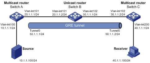
Network requirements
Multicast routing and PIM-SM are enabled on Switch A and Switch C. Switch B does not support multicast. Switch A acts the C-BSR and the C-RP. OSPF is running on Switch A, Switch B, and Switch C.
Perform the configuration so that the receiver host can receive the multicast data from the source.
Configuration procedure
1. Configure the IP address and subnet mask for each interface as shown in Figure 6. (Details not shown.)
2. Enable OSPF on switches to make sure the network-layer among the switches is interoperable and the routing information among the switches can be dynamically updated. (Details not shown.)
3. Configure a GRE tunnel:
# Create interface Tunnel 0 on Switch A and specify the tunnel encapsulation mode as GRE over IPv4.
[SwitchA] interface tunnel 0 mode gre
# Configure the IP address for interface Tunnel 0 on Switch A and specify its source and destination addresses.
[SwitchA-Tunnel0] ip address 50.1.1.1 24
[SwitchA-Tunnel0] source 20.1.1.1
[SwitchA-Tunnel0] destination 30.1.1.2
[SwitchA-Tunnel0] quit
# Create interface Tunnel 0 on Switch C and specify the tunnel encapsulation mode as GRE over IPv4.
[SwitchC] interface tunnel 0 mode gre
# Configure the IP address for interface Tunnel 0 on Switch C and specify its source and destination addresses.
[SwitchC-Tunnel0] ip address 50.1.1.2 24
[SwitchC-Tunnel0] source 30.1.1.2
[SwitchC-Tunnel0] destination 20.1.1.1
[SwitchC-Tunnel0] quit
4. Enable IP multicast routing, PIM-SM, and IGMP:
# On Switch A, enable multicast routing globally and enable PIM-SM on each interface.
[SwitchA] multicast routing-enable
[SwitchA] interface vlan-interface 100
[SwitchA-Vlan-interface100] pim sm
[SwitchA-Vlan-interface100] quit
[SwitchA] interface vlan-interface 101
[SwitchA-Vlan-interface101] pim sm
[SwitchA-Vlan-interface101] quit
[SwitchA] interface tunnel 0
[SwitchA-Tunnel0] pim sm
[SwitchA-Tunnel0] quit
# On Switch C, enable multicast routing globally, enable IGMP on VLAN-interface 200, and enable PIM-SM on each interface.
[SwitchC] multicast routing-enable
[SwitchC] interface vlan-interface 200
[SwitchC-Vlan-interface200] igmp enable
[SwitchC-Vlan-interface200] pim sm
[SwitchC-Vlan-interface200] quit
[SwitchC] interface vlan-interface 102
[SwitchC-Vlan-interface102] pim sm
[SwitchC-Vlan-interface102] quit
[SwitchC] interface tunnel 0
[SwitchC-Tunnel0] pim sm
[SwitchC-Tunnel0] quit
5. Configure Switch A as the C-BSR and the C-RP.
[SwitchA] pim
[SwitchA-pim] c-bsr 20.1.1.1
[SwitchA-pim] c-rp 20.1.1.1
[SwitchA-pim] quit
6. On Switch C, configure a static multicast route, specifying the RPF neighbor toward the source as interface Tunnel 0 on Switch A.
[SwitchC] ip rpf-route-static 50.1.1.0 24 50.1.1.1
Verifying the configuration
The source sends the multicast data to the multicast group 225.1.1.1 and the receiver host can receive the multicast data after joining the multicast group. You can use the display pim routing-table command to display PIM routing table information. For example:
# Display PIM routing table information on Switch C.
[SwitchC] display pim routing-table
Total 1 (*, G) entry; 3 (S, G) entries
(*, 225.1.1.1)
RP: 20.1.1.2 (local)
Protocol: pim-sm, Flag: WC
UpTime: 00:11:43
Upstream interface: Register-Tunnel0
Upstream neighbor: NULL
RPF prime neighbor: NULL
Downstream interface(s) information:
Total number of downstreams: 1
1: Vlan200
Protocol: igmp, UpTime: 00:11:43, Expires: -
(10.1.1.100, 225.1.1.1)
RP: 20.1.1.2 (local)
Protocol: pim-sm, Flag: SPT ACT
UpTime: 00:06:07
Upstream interface: Tunnel0
Upstream neighbor: 50.1.1.1
RPF prime neighbor: 50.1.1.1
Downstream interface(s) information:
Total number of downstreams: 1
1: Vlan200
Protocol: pim-sm, UpTime: 00:06:07, Expires: -
The output shows that Switch A is the RPF neighbor of Switch C and the multicast data from Switch A is delivered over a GRE tunnel to Switch C.
Troubleshooting multicast routing and forwarding
Static multicast route failure
Symptom
No dynamic routing protocol is enabled on the routers, and the physical status and link layer status of interfaces are both up, but the static multicast route fails.
Analysis
· If a static multicast route is not correctly configured or updated to match the current network conditions, it does not exist in the static multicast routing table.
· If a better route is found, the static multicast route might also fail.
Solution
1. Use the display multicast routing-table static command to display information about static multicast routes to verify that the static multicast route has been correctly configured and the route entry exists in the static multicast routing table.
2. Check the type of the interface that connects the static multicast route to the RPF neighbor. If the interface is not a point-to-point interface, be sure to specify the address for the RPF neighbor.