- Table of Contents
-
- H3C S5500-EI Series Switches Operation Manual-Release 2102(V1.01)
- 00-Preface
- 01-CLI configuration
- 02-RBAC configuration
- 03-Login management configuration
- 04-FTP and TFTP configuration
- 05-File system management configuration
- 06-Configuration file management configuration
- 07-Software upgrade configuration
- 08-Emergency shell configuration
- 09-Automatic configuration
- 10-Device management configuration
- 11-Tcl configuration
- 12-Python configuration
- 13-License management
- Related Documents
-
| Title | Size | Download |
|---|---|---|
| 34-RRPP Configuration | 684 KB |
Table of Contents
1.2 RRPP Configuration Task List
1.3.2 Master Node Configuration Example
1.4.2 Transit Node Configuration Example
1.5.2 Edge Node Configuration Example
1.6 Configuring Assistant Edge Node
1.6.2 Assistant Edge Node Configuration Example
1.7 Displaying and Maintaining RRPP
1.8 RRPP Typical Configuration Examples
1.8.1 Configuring Single Ring Topology
1.8.2 Configuring Single-Domain Intersecting Ring Topology
1.8.3 Configuring Multi-Domain Intersecting Ring Topology
Chapter 1 RRPP Configuration
When configuring RRPP, go to these sections for information you are interested in:
l RRPP Configuration Task List
l Configuring Assistant Edge Node
l Displaying and Maintaining RRPP
l RRPP Typical Configuration Examples
1.1 RRPP Overview
Rapid Ring Protection Protocol (RRPP) is an Ethernet ring-specific link layer protocol. It can not only prevent data loop from causing broadcast storm efficiently when the Ethernet ring is complete, but also restore communication channels among nodes on the Ethernet ring rapidly when a link is torn down.
Compared with Spanning Tree Protocol (STP), RRPP features:
l Expedited topology convergence
l Independent of the number of nodes on the Ethernet ring
1.1.1 Basic Concepts in RRPP
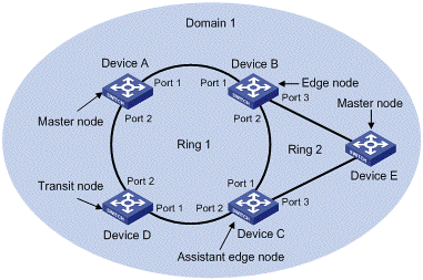
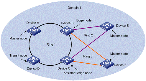
Figure 1-1 RRPP networking diagram
I. RRPP domain
The interconnected devices with the same domain ID and control VLANs constitute an RRPP domain. An RRPP domain contains multiple RRPP rings, in which one ring serves as the primary ring and other rings serve as subrings. You can set a ring as either the primary ring or a subring.
As shown in Figure 1-1, Domain 1 is an RRPP domain, including two RRPP rings: Ring 1 and Ring 2. All the nodes on the two RRPP rings belong to the RRPP domain.
II. RRPP ring
A ring-shaped Ethernet topology is called an RRPP ring. An RRPP domain is built up on an RRPP ring. An RRPP ring falls into primary ring and subring. Both levels are set to 0 and 1 respectively when configuration.
As shown in Figure 1-1, Domain 1 contains two RRPP rings: Ring 1 and Ring 2. Ring 1 level is set to 0, meaning the primary ring; Ring 2 level is set to 1, meaning the subring.
For a ring, there are two cases:
l Health state: All the physical links on the Ethernet ring are connected.
l Disconnect state: Some physical link on the Ethernet ring fails.
III. Control VLAN and data VLAN
l Control VLAN is a VLAN specially designed to transfer RRPP packets. The ports accessing an RRPP ring on devices belong to the control VLAN of the ring and only these ports can join this VLAN. IP address configuration is prohibited on the ports of the control VLAN. You can configure a control VLAN for the primary ring (namely the primary control VLAN). However, the control VLAN of a subring (namely the secondary control VLAN) is assigned automatically by the system and its VLAN ID is the control VLAN ID of the primary ring plus 1.
l Data VLAN is a VLAN designed to transfer data packets, including the ports accessing the Ethernet ring and other ports on devices.
IV. Node
Every device on an RRPP ring is referred to as a node. Node mode includes:
l Master node: Each ring has a master node primarily used to make loop detection and loop guard.
l Transit node: All the nodes excluding the master node on the primary ring; and all the nodes on a subring except for the master node and the nodes where the primary ring intersects with the subring.
l Edge node: A node residing on the primary ring and a subring at the same time. The node is a special transit node that serves as a transit node on the primary ring and an edge node on the subring.
l Assistant-edge node: A node residing on the primary ring and a subring at the same time. The node is a special transit node that serves as a transit node on the primary ring and an assistant-edge node on the subring. This node is used in conjunction with the edge node to detect the integrity of the primary ring and perform loop guard.
As shown in Figure 1-1, Ring 1 is the primary ring and Ring 2 is a subring. Device A is the master node of Ring 1, Device B, Device C and Device D are the transit nodes of Ring 1; Device E is the master node of Ring 2, Device B is the edge node of Ring 2, and Device C is the assistant edge node of Ring 2.
V. Primary port and secondary port
Each master node or transit node has two ports accessing an RRPP ring, in which one serves as the primary port and the other serves as the secondary port. You can determine the role of a port.
1) In terms of functionality, the difference between the primary port and the secondary port of a master node is:
l The primary port and the secondary port are designed to play the role of sending and receiving loop-detect packets respectively.
l When an RRPP ring is in health state, the secondary port of the master node will logically deny data VLANs and permit only the packets of the control VLANs.
l When an RRPP ring is in disconnect state, the secondary port of the master node will permit data VLANs, that is, forward packets of data VLANs.
2) In terms of functionality, there is no difference between the primary port and the secondary port of the transit node. Both are designed for the transfer of protocol packets and data packets over an RRPP ring.
As shown in Figure 1-1, Device A is the master node of Ring 1. Port 1 and port 2 are the primary port and the secondary port of the master node on Ring 1 respectively. Device B, Device C and Device D are the transit nodes of Ring 1. Their port 1 and port 2 are the primary port and the secondary port on Ring 1 respectively.
VI. Common port and edge port
Each edge node or assistant edge node have two ports accessing a subring, with one being a common port and the other being an edge port. Common port is a port accessing the primary ring and a subring simultaneously; and edge port is a port accessing only a subring.
As shown in Figure 1-1, Device B and Device C lie on Ring 1 and Ring 1. Device B’s port 2 and Device C’s port 1 access the primary ring and a subring at the same time, so they are common ports. Device B’s port 3 and Device C’s port 3 access only a subring, so they are edge ports.
VII. Multi-domain intersection common port
Of the two ports on a node where rings of different domains intersect, the common port is the one on the primary ring that belongs to different domains at the same time. This port must not be on a subring. The role of the port is determined by user configuration.
VIII. Timers
The master node uses two timers to send and receive RRPP packets: the Hello timer and the Fail timer.
l The Hello timer is used for the primary port to send Health packets.
l The Fail timer is used for the secondary port to receive Health packets from the master node.
If the secondary port receives the Health packets before the Fail timer expires, the overall ring is in health state. Otherwise, the ring transits into disconnect state until the secondary port receives the Health packet again.
& Note:
l In an RRPP domain, a transit node learns the Hello timer value and the Fail timer value on the master node through the received Health packets, guaranteeing the consistency of two timer values across a ring.
l The Fail timer value must be greater than or equal to 3 times of the Hello timer value.
1.1.2 RRPP Packets
Table 1-1 shows the types of RRPP packets and their functions.
Table 1-1 RRPP packet types and their functions
|
Type |
Description |
|
Health |
The master node initiates Health packets to detect the integrity of a ring in a network. |
|
Link-Down |
The transit node, the edge node or the assistant edge node initiates Link-Down packets to notify the master node the disappearance of a ring in case of a link failure. |
|
Common-Flush-FDB |
The master node initiates Common-Flush-FDB packets to notify the transit nodes to update their own MAC entries and ARP entries when an RRPP ring transits to disconnect state. |
|
Complete-Flush-FDB |
The master node initiates Complete-Flush-FDB packets to notify the transit nodes to update their own MAC entries and ARP entries, and release from blocking ports temporarily when an RRPP ring transits into health state. |
|
Edge-Hello |
The edge node initiates Edge-Hello packets to examine the links of the primary ring between the edge node and the assistant edge node. |
|
Major-Fault |
Assistant edge node initiates Major-Fault packets to notify the edge node of a failure when a link of primary ring between edge node and assistant edge node is torn down. |
1.1.3 Typical RRPP Networking
Here are several typical networking applications.
I. Single ring
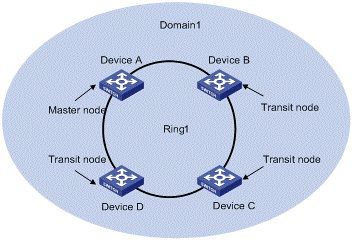
Figure 1-2 Single ring
There is only a single ring in the network topology. In this case, you only need to define an RRPP domain.
II. Multi-domain tangent rings
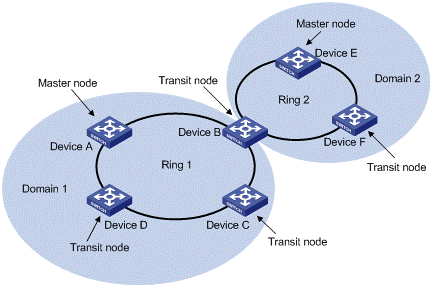
Figure 1-3 Multi-domain tangent rings
There are two or more rings in the network topology and only one common node between rings. In this case, you need define an RRPP domain for each ring.
III. Single-domain intersecting rings
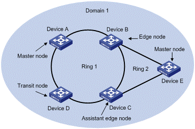
Figure 1-4 Single-domain intersecting rings
There are two or more rings in the network topology and two common nodes between rings. In this case, you only need to define an RRPP domain, and set one ring as the primary ring and other rings as subrings.
IV. Dual homed rings
V. Multi-domain intersecting rings
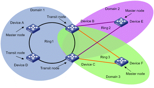
Figure 1-6 Multi-domain intersecting rings
There are two or more domains in a network, and there two different common nodes between any two domains. Figure 1-6 defines three RRPP domains, each containing one and only one RRPP primary ring. In the case of multi-domain intersection, the rings in different domains are independently configured. Each single domain can contain multiple rings, among which there must be one and only one primary ring. The data VLAN in one domain must be isolated from the data VLAN in another.
1.1.4 How RRPP Works
I. Polling mechanism
The primary port of the master node sends Health packets across the control VLAN periodically.
l If the ring works properly, the secondary port of the master node will receive Health packets and the master node will maintain it in block state.
l If the ring is torn down, the secondary port of the master node will not receive Health packets after the timeout timer expires. The master node will release the secondary port from blocking data VLAN while sending Common-Flush-FDB packets to notify all transit nodes to update their own MAC entries and ARP entries.
II. Link down alarm mechanism
The transit node, the edge node or the assistant edge node sends Link-Down packets to the master node immediately when they find any port belonging to an RRPP domain is down. Upon the receipt of a Link-Down packet, the master node releases the secondary port from blocking data VLAN while sending Common-Flush-FDB packet to notify all the transit nodes, the edge nodes and the assistant nodes to update their own MAC entries and ARP entries.
III. Ring recovery
The master node may find the ring is restored after a period of time after the ports belonging to the RRPP domain on the transit node, the edge node or the assistant edge node are up again. A temporary loop may arise in the data VLAN in this period. As a result, broadcast storm occurs.
IV. Broadcast storm suppression mechanism in a multi-homed subring in case of primary ring link failure
As shown in Figure 1-5, Ring 1 is the primary ring, and Ring 2 and Ring 3 are subrings. When two links of the primary ring between the edge node and the assistant edge node are down, the master nodes of Ring 2 and Ring 3 will open their respective secondary ports, and thus a loop among B, C, E and F is generated. As a result, broadcast storm occurs.
1.1.5 Protocols and Standards
Related standard: RFC 3619.
1.2 RRPP Configuration Task List
Complete the following tasks to configure RRPP
|
Task |
Description |
|
Required |
|
|
Optional |
|
|
Optional |
|
|
Optional |
![]() Caution:
Caution:
l It is recommended to configure the primary ring first and then the subring when you configure an RRPP domain. Moreover, a Ring ID cannot be applied to more than one RRPP ring in one RRPP domain.
l If a device lies on multiple RRPP rings in an RRPP domain, only one primary ring exists. The device serves as either an edge node or an assistant edge node on the subrings.
l The total number of rings configured on a device in all RRPP domains should not be greater than 16.
l Modification of node mode, port role and ring level of an RRPP ring is prohibited after configuration. If needed, you must first delete the existing configuration.
l The secondary port on the master node and a port on a subring node must not be configured as a multi-domain intersection common port, and the two ports that access the same node to the same RRPP ring must not be configured as multi-domain intersection common ports at the same time.
l When configuring multi-domain intersecting rings, do not enable or disable the RRPP ring on which the multi-domain intersection common port resides with RRPP globally enabled.
l In the case of multi-domain intersection, the rings in different domains are independently configured. Each single domain can contain multiple rings, among which there must be one and only one primary ring. The data VLAN in one domain must be isolated from the data VLAN in another.
The ports accessing an RRPP ring must conform to the following conditions:
l Trunk port;
l Layer 2 GE port;
l Except for aggregation port and loopback port;
l Port with STP, QinQ, 802.1x, MAC address authentication, voice VLAN disabled;
l Do not enable OAM remote loopback function on an RRPP port. Otherwise, this may cause temporary broadcast storm;
l Enable link status rapid report function on a port accessing an RRPP ring (the link-delay of the port is set to 0) to accelerate topology convergence.
& Note:
l If you need to transparently transmit RRPP packets on a device without enabling RRPP, you should ensure only the two ports accessing an RRPP ring permits the packets of the control VLAN. Otherwise, the packets from other VLANs may go into the control VLAN in transparent transmission mode and strike the RRPP ring.
l Do not set the default VLAN ID of a port accessing an RRPP ring to primary control VLAN ID or secondary control VLAN ID (the latter is equal to the former plus 1), avoiding the influence on the proper receiving/sending of RRPP packets.
1.3 Configuring Master Node
1.3.1 Configuration Procedure
Follow these steps to configure master node:
|
To do… |
Use the command… |
Remarks |
|
Enter system view |
system-view |
— |
|
Create an RRPP domain and enter its view |
rrpp domain domain-id |
Required |
|
Specify control VLAN for the RRPP domain |
control-vlan vlan-id |
Required |
|
Specify the current device as the master node of the ring, and specify the primary port and the secondary port |
ring ring-id node-mode master [ primary-port interface-type interface-number ] [ secondary-port interface-type interface-number ] level level-value |
Required |
|
Configure the timer for the RRPP domain |
timer hello-timer hello-value fail-timer fail-value |
Optional By default, the Hello timer value is 1 second and the Fail timer value is 3 seconds. |
|
Enable the RRPP ring |
ring ring-id enable |
Required By default, the RRPP ring is disabled. |
|
Return to system view |
quit |
— |
|
Enable RRPP |
rrpp enable |
Required By default, RRPP is disabled. |
![]() Caution:
Caution:
l The control VLAN configured for an RRPP domain must be a new one.
l Control VLAN configuration is required for configuring an RRPP ring.
l To use the undo rrpp domain command to remove an RRPP domain, you must ensure the RRPP domain has no RRPP ring.
1.3.2 Master Node Configuration Example
I. Network requirements
l Specify the device in RRPP domain 1;
l Set VLAN 4092 as the control VLAN;
l Specify the device as the master node of primary ring 1 in RRPP domain 1, GigabitEthernet 1/0/1 as the primary port and GigabitEthernet 1/0/2 as the secondary port;
l Set the Hello timer value to 2 seconds and the Fail timer value to 7 seconds.
II. Configuration procedure
<Sysname> system-view
[Sysname] interface gigabitethernet 1/0/1
[Sysname-GigabitEthernet1/0/1] link-delay 0
[Sysname-GigabitEthernet1/0/1] quit
[Sysname] interface gigabitethernet 1/0/2
[Sysname-GigabitEthernet1/0/2] link-delay 0
[Sysname-GigabitEthernet1/0/2] quit
[Sysname] rrpp domain 1
[Sysname-rrpp-domain1] control-vlan 4092
[Sysname-rrpp-domain1] ring 1 node-mode master primary-port gigabitethernet 1/0/1 secondary-port gigabitethernet 1/0/2 level 0
[Sysname-rrpp-domain1] timer hello-timer 2 fail-timer 7
[Sysname-rrpp-domain1] ring 1 enable
[Sysname-rrpp-domain1] quit
[Sysname] rrpp enable
1.4 Configuring Transit Node
1.4.1 Configuration Procedure
Follow these steps to configure transit node:
|
To do… |
Use the command… |
Remarks |
|
Enter system view |
system-view |
— |
|
Create an RRPP domain and enter its view |
rrpp domain domain-id |
Required |
|
Specify a control VLAN for the RRPP domain |
control-vlan vlan-id |
Required |
|
Specify the current device as the transit node of the ring, and specify the primary port and the secondary port |
ring ring-id node-mode transit [ primary-port interface-type interface-number ] [ secondary-port interface-type interface-number ] level level-value |
Required |
|
Enable the RRPP ring |
ring ring-id enable |
Required By default, the RRPP ring is disabled. |
|
Return to system view |
quit |
— |
|
Enable RRPP |
rrpp enable |
Required By default, RRPP is disabled. |
![]() Caution:
Caution:
l The control VLAN configured for an RRPP domain must be a new one.
l Control VLAN configuration is required for configuring an RRPP ring.
l To use the undo rrpp domain command to remove an RRPP domain, you must ensure the RRPP domain has no RRPP ring.
1.4.2 Transit Node Configuration Example
I. Network requirements
l Specify the device in RRPP domain 1;
l Set VLAN 4092 as the control VLAN;
l Specify the device as the transit node of primary ring 1 in RRPP domain 1, GigabitEthernet 1/0/1 as the primary port and GigabitEthernet 1/0/2 as the secondary port.
II. Configuration procedure
<Sysname> system-view
[Sysname] interface gigabitethernet 1/0/1
[Sysname-GigabitEthernet1/0/1] link-delay 0
[Sysname-GigabitEthernet1/0/1] quit
[Sysname] interface gigabitethernet 1/0/2
[Sysname-GigabitEthernet1/0/2] link-delay 0
[Sysname-GigabitEthernet1/0/2] quit
[Sysname] rrpp domain 1
[Sysname-rrpp-domain1] control-vlan 4092
[Sysname-rrpp-domain1] ring 1 node-mode transit primary-port gigabitethernet 1/0/1 secondary-port gigabitethernet 1/0/2 level 0
[Sysname-rrpp-domain1] ring 1 enable
[Sysname-rrpp-domain1] quit
[Sysname] rrpp enable
1.5 Configuring Edge Node
1.5.1 Configuration Procedure
Follow these steps to configure edge node:
|
To do… |
Use the command… |
Remarks |
|
Enter system view |
system-view |
— |
|
Create an RRPP domain and enter its view |
rrpp domain domain-id |
Required |
|
Specify a control VLAN for the RRPP domain |
control-vlan vlan-id |
Required |
|
Specify the current device as the transit node of the primary ring, and specify the primary port and the secondary port |
ring ring-id node-mode transit [ primary-port interface-type interface-number ] [ secondary-port interface-type interface-number ] level level-value |
Required |
|
Specify the current device as the edge node of a subring, and specify the common port and the edge port |
ring ring-id node-mode edge [ common-port interface-type interface-number ] [ edge-port interface-type interface-number ] |
Required |
|
Enable the primary ring |
ring ring-id enable |
Required By default, the RRPP ring is disabled. |
|
Enable the subring |
ring ring-id enable |
Required By default, the RRPP ring is disabled. |
|
Return to system view |
quit |
— |
|
Enable RRPP |
rrpp enable |
Required By default, RRPP is disabled. |
![]() Caution:
Caution:
l The control VLAN configured for an RRPP domain must be a new one.
l Control VLAN configuration is required for configuring an RRPP ring.
l A Ring ID cannot be applied to more than one RRPP ring in an RRPP domain.
l You must first configure the primary ring and then the subring when configuring an edge node. Moreover, you must remove all subring configurations before deleting the primary ring configuration of an edge node. However, the RRPP ring enabled cannot be deleted.
l To use the undo rrpp domain command to remove an RRPP domain, you must ensure the RRPP domain has no RRPP ring.
1.5.2 Edge Node Configuration Example
I. Networking requirements
l Specify the device in RRPP domain 1;
l Set VLAN 4092 as the control VLAN;
l Specify the device as the transit node of primary ring 1 in RRPP domain 1, GigabitEthernet 1/0/1 as the primary port and GigabitEthernet 1/0/2 as the secondary port;
l Specify the device as the edge node of subring 2 in RRPP domain 1, GigabitEthernet 1/0/2 as a common port and GigabitEthernet 1/0/4 as an edge port.
II. Configuration procedure
<Sysname> system-view
[Sysname] interface gigabitethernet 1/0/1
[Sysname-GigabitEthernet1/0/1] link-delay 0
[Sysname-GigabitEthernet1/0/1] quit
[Sysname] interface gigabitethernet 1/0/2
[Sysname-GigabitEthernet1/0/2] link-delay 0
[Sysname-GigabitEthernet1/0/2] quit
[Sysname] interface gigabitethernet 1/0/4
[Sysname-GigabitEthernet1/0/4] link-delay 0
[Sysname-GigabitEthernet1/0/4] quit
[Sysname] rrpp domain 1
[Sysname-rrpp-domain1] control-vlan 4092
[Sysname-rrpp-domain1] ring 1 node-mode transit primary-port gigabitethernet 1/0/1 secondary-port gigabitethernet 1/0/2 level 0
[Sysname-rrpp-domain1] ring 2 node-mode edge common-port gigabitethernet 1/0/2 edge-port gigabitethernet 1/0/4
[Sysname-rrpp-domain1] ring 1 enable
[Sysname-rrpp-domain1] ring 2 enable
[Sysname-rrpp-domain1] quit
[Sysname] rrpp enable
1.6 Configuring Assistant Edge Node
1.6.1 Configuration Procedure
Follow these steps to configure assistant edge node:
|
To do… |
Use the command… |
Remarks |
|
Enter system view |
system-view |
— |
|
Create an RRPP domain and enter its view |
rrpp domain domain-id |
Required |
|
Specify a control VLAN for the RRPP domain |
control-vlan vlan-id |
Required |
|
Specify the current device as the transit node of the primary ring, and specify the primary port and the secondary port |
ring ring-id node-mode transit [ primary-port interface-type interface-number ] [ secondary-port interface-type interface-number ] level level-value |
Required |
|
Specify the current device as the assistant edge node of the subring, and specify a common port and an edge port |
ring ring-id node-mode assistant-edge [ common-port interface-type interface-number ] [ edge-port interface-type interface-number ] |
Required |
|
Enable the primary ring |
ring ring-id enable |
Required By default, the RRPP ring is disabled. |
|
Enable the subring |
ring ring-id enable |
Required By default, the RRPP ring is disabled. |
|
Return to system view |
quit |
— |
|
Enable RRPP |
rrpp enable |
Required By default, RRPP is disabled. |
![]() Caution:
Caution:
l The control VLAN configured for an RRPP domain must be a new one.
l Control VLAN configuration is required for configuring an RRPP ring.
l A Ring ID cannot be applied to more than on RRPP ring in an RRPP domain.
l You must first configure the primary ring and then the subring when configuring an edge node. Moreover, you must remove all subring configurations before deleting the primary ring configuration of an edge node. However, the RRPP ring enabled cannot be deleted.
l To use the undo rrpp domain command to remove an RRPP domain, you must ensure the RRPP domain has no RRPP ring.
1.6.2 Assistant Edge Node Configuration Example
I. Networking requirements
l Specify the device in RRPP domain 1;
l Set VLAN 4092 as the control VLAN;
l Specify the device as the transit node of primary ring 1 in RRPP domain 1, GigabitEthernet 1/0/1 as the primary port and GigabitEthernet 1/0/2 as the secondary port;
l Specify the device as the assistant edge node of subring 2 in RRPP domain 1, GigabitEthernet 1/0/2 as the common port and GigabitEthernet 1/0/4 as the edge port.
II. Configuration procedure
<Sysname> system-view
[Sysname] interface gigabitethernet 1/0/1
[Sysname-GigabitEthernet1/0/1] link-delay 0
[Sysname-GigabitEthernet1/0/1] quit
[Sysname] interface gigabitethernet 1/0/2
[Sysname-GigabitEthernet1/0/2] link-delay 0
[Sysname-GigabitEthernet1/0/2] quit
[Sysname] interface gigabitethernet 1/0/4
[Sysname-GigabitEthernet1/0/4] link-delay 0
[Sysname-GigabitEthernet1/0/4] quit
[Sysname] rrpp domain 1
[Sysname-rrpp-domain1] control-vlan 4092
[Sysname-rrpp-domain1] ring 1 node-mode transit primary-port gigabitethernet 1/0/1 secondary-port gigabitethernet 1/0/2 level 0
[Sysname-rrpp-domain1] ring 2 node-mode assistant-edge common-port gigabitethernet 1/0/2 edge-port gigabitethernet 1/0/4
[Sysname-rrpp-domain1] ring 1 enable
[Sysname-rrpp-domain1] ring 2 enable
[Sysname-rrpp-domain1] quit
[Sysname] rrpp enable
1.7 Displaying and Maintaining RRPP
|
To do… |
Use the command… |
Remarks |
|
Display brief information about RRPP configuration |
display rrpp brief |
Available in any view |
|
Display detailed information about RRPP configuration |
display rrpp verbose domain domain-id [ ring ring-id ] |
|
|
Display RRPP statistics |
display rrpp statistics domain domain-id [ ring ring-id ] |
|
|
Clear RRPP statistics |
reset rrpp statistics domain domain-id [ ring ring-id ] |
Available in user view |
1.8 RRPP Typical Configuration Examples
This section covers these topics:
l Configuring Single Ring Topology
l Configuring Intersecting Ring Topology
1.8.1 Configuring Single Ring Topology
I. Networking requirements
l Device A, Device B, Device C and Device D constitute RRPP domain 1;
l Specify the control VLAN of RRPP domain 1 as VLAN 4092;
l Device A, Device B, Device C and Device D constitute primary ring 1;
l Specify Device A as the master node of primary ring 1, GigabitEthernet 1/0/1 as the primary port and GigabitEthernet 1/0/2 as the secondary port;
l Specify Device B, Device C and Device D as the transit nodes of primary ring 1, their GigabitEthernet 1/0/1 as the primary port and GigabitEthernet 1/0/2 as the secondary port;
l The timers of the primary ring adopt the default value.
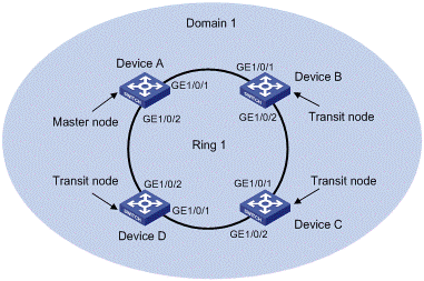
Figure 1-7 Single ring networking diagram
II. Configuration considerations
First, determine the node mode of a device in an RRPP ring, and then perform the following configurations on a per-device basis:
l Create an RRPP domain.
l Specify the control VLAN for the RRPP domain.
l Specify the node mode of a device on the primary ring and the ports accessing the RRPP ring on the device.
l Enable the RRPP ring.
l Enable RRPP
III. Configuration procedure
1) Perform the following configuration on Device A:
<Device A> system-view
[DeviceA] interface gigabitethernet 1/0/1
[DeviceA-GigabitEthernet1/0/1] link-delay 0
[DeviceA-GigabitEthernet1/0/1] quit
[DeviceA] interface gigabitethernet 1/0/2
[DeviceA-GigabitEthernet1/0/2] link-delay 0
[DeviceA-GigabitEthernet1/0/2] quit
[Device A] rrpp domain 1
[Device A-rrpp-domain1] control-vlan 4092
[Device A-rrpp-domain1] ring 1 node-mode master primary-port gigabitethernet 1/0/1 secondary-port gigabitethernet 1/0/2 level 0
[Device A-rrpp-domain1] ring 1 enable
[Device A-rrpp-domain1] quit
[Device A] rrpp enable
2) Perform the following configuration on Device B:
<Device B> system-view
[DeviceB] interface gigabitethernet 1/0/1
[DeviceB-GigabitEthernet1/0/1] link-delay 0
[DeviceB-GigabitEthernet1/0/1] quit
[DeviceB] interface gigabitethernet 1/0/2
[DeviceB-GigabitEthernet1/0/2] link-delay 0
[DeviceB-GigabitEthernet1/0/2] quit
[Device B] rrpp domain 1
[Device B-rrpp-domain1] control-vlan 4092
[Device B-rrpp-domain1] ring 1 node-mode transit primary-port gigabitethernet 1/0/1 secondary-port gigabitethernet 1/0/2 level 0
[Device B-rrpp-domain1] ring 1 enable
[Device B-rrpp-domain1] quit
[Device B] rrpp enable
3) Perform the following configuration on Device C:
<Device C> system-view
[DeviceC] interface gigabitethernet 1/0/1
[DeviceC-GigabitEthernet1/0/1] link-delay 0
[DeviceC-GigabitEthernet1/0/1] quit
[DeviceC] interface gigabitgigabitethernet 1/0/0/2
[DeviceC-GigabitEthernet1/0/2] link-delay 0
[DeviceC-GigabitEthernet1/0/2] quit
[Device C] rrpp domain 1
[Device C-rrpp-domain1] control-vlan 4092
[Device C-rrpp-domain1] ring 1 node-mode transit primary-port gigabitethernet 1/0/1 secondary-port gigabitethernet 1/0/2 level 0
[Device C-rrpp-domain1] ring 1 enable
[Device C-rrpp-domain1] quit
[Device C] rrpp enable
4) Perform the following configuration on Device D:
<Device D> system-view
[DeviceD] interface gigabitethernet 1/0/1
[DeviceD-GigabitEthernet1/0/1] link-delay 0
[DeviceD-GigabitEthernet1/0/1] quit
[DeviceD] interface gigabitethernet 1/0/2
[DeviceD-GigabitEthernet1/0/2] link-delay 0
[DeviceD-GigabitEthernet1/0/2] quit
[Device D] rrpp domain 1
[Device D-rrpp-domain1] control-vlan 4092
[Device D-rrpp-domain1] ring 1 node-mode transit primary-port gigabitethernet 1/0/1 secondary-port gigabitethernet 1/0/2 level 0
[Device D-rrpp-domain1] ring 1 enable
[Device D-rrpp-domain1] quit
[Device D] rrpp enable
After the above configuration, you can use the display command to view RRPP configuration.
1.8.2 Configuring Single-Domain Intersecting Ring Topology
I. Networking requirements
l Device A, Device B, Device C and Device D constitute RRPP domain 1.
l VLAN 4092 is the control VLAN of RRPP domain 1;
l Device A, Device B, Device C and Device D constitute primary ring 1;
l Device B, Device C and Device E constitute subring 2;
l Device A is the master node of primary ring 1, GigabitEthernet 1/0/1 is the primary port and GigabitEthernet 1/0/2 is the secondary port;
l Device E is the master node of subring 2, GigabitEthernet 1/0/1 is the primary port and GigabitEthernet 1/0/2 is the secondary port;
l Device B is the transit node of primary ring 1 and the edge node of subring 2, GigabitEthernet 1/0/2 is the common port and GigabitEthernet 1/0/3 is the edge port;
l Device C is the transit node of primary ring 1 and the assistant edge node of subring 1, GigabitEthernet 1/0/1 is the common port and GigabitEthernet 1/0/3 is the edge port;
l Device D is the transit node of primary ring 1, GigabitEthernet 1/0/1 is the primary port and GigabitEthernet 1/0/2 is the secondary port;
l The timers of both the primary ring and the subring adopt the default value.
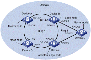
Figure 1-8 Networking diagram for single-domain intersecting rings configuration
II. Configuration considerations
First, determine the primary ring and subring in an RRPP domain, node mode of a device on each RRPP ring, and then perform the following configuration on a per-device basis:
l Create an RRPP domain.
l Specify the control VLAN for the RRPP domain.
l Specify the node mode of a device on an RRPP ring and the ports accessing the RRPP ring on the device.
l Enable these two RRPP rings.
l Enable RRPP
III. Configuration procedure
1) Perform the following configuration on Device A:
<Device A> system-view
[DeviceA] interface gigabitethernet 1/0/1
[DeviceA-GigabitEthernet1/0/1] link-delay 0
[DeviceA-GigabitEthernet1/0/1] quit
[DeviceA] interface gigabitethernet 1/0/2
[DeviceA-GigabitEthernet1/0/2] link-delay 0
[DeviceA-GigabitEthernet1/0/2] quit
[Device A] rrpp domain 1
[Device A-rrpp-domain1] control-vlan 4092
[Device A-rrpp-domain1] ring 1 node-mode master primary-port gigabitethernet 1/0/1 secondary-port gigabitethernet 1/0/2 level 0
[Device A-rrpp-domain1] ring 1 enable
[Device A-rrpp-domain1] quit
[Device A] rrpp enable
2) Perform the following configuration on Device B:
<Device B> system-view
[DeviceB] interface gigabitethernet 1/0/1
[DeviceB-GigabitEthernet1/0/1] link-delay 0
[DeviceB-GigabitEthernet1/0/1] quit
[DeviceB] interface gigabitethernet 1/0/2
[DeviceB-GigabitEthernet1/0/2] link-delay 0
[DeviceB-GigabitEthernet1/0/2] quit
[DeviceB] interface gigabitethernet 1/0/3
[DeviceB-GigabitEthernet1/0/3] link-delay 0
[DeviceB-GigabitEthernet1/0/3] quit
[Device B] rrpp domain 1
[Device B-rrpp-domain1] control-vlan 4092
[Device B-rrpp-domain1] ring 1 node-mode transit primary-port gigabitethernet 1/0/1 secondary-port gigabitethernet 1/0/2 level 0
[Device B-rrpp-domain1] ring 2 node-mode edge common-port gigabitethernet 1/0/2 edge-port gigabitethernet 1/0/3
[Device B-rrpp-domain1] ring 1 enable
[Device B-rrpp-domain1] ring 2 enable
[Device B-rrpp-domain1] quit
[Device B] rrpp enable
3) Perform the following configuration on Device C:
<Device C> system-view
[DeviceC] interface gigabitethernet 1/0/1
[DeviceC-GigabitEthernet1/0/1] link-delay 0
[DeviceC-GigabitEthernet1/0/1] quit
[DeviceC] interface gigabitethernet 1/0/2
[DeviceC-GigabitEthernet1/0/2] link-delay 0
[DeviceC-GigabitEthernet1/0/2] quit
[DeviceC] interface gigabitethernet 1/0/3
[DeviceC-GigabitEthernet1/0/3] link-delay 0
[DeviceC-GigabitEthernet1/0/3] quit
[Device C] rrpp domain 1
[Device C-rrpp-domain1] control-vlan 4092
[Device C-rrpp-domain1] ring 1 node-mode transit primary-port gigabitethernet 1/0/1 secondary-port gigabitethernet 1/0/2 level 0
[Device C-rrpp-domain1] ring 2 node-mode assistant-edge common-port gigabitethernet 1/0/1 edge-port gigabitethernet 1/0/3
[Device C-rrpp-domain1] ring 1 enable
[Device C-rrpp-domain1] ring 2 enable
[Device C-rrpp-domain1] quit
[Device C] rrpp enable
4) Perform the following configuration on Device D:
<Device D> system-view
[DeviceD] interface gigabitethernet 1/0/1
[DeviceD-GigabitEthernet1/0/1] link-delay 0
[DeviceD-GigabitEthernet1/0/1] quit
[DeviceD] interface gigabitethernet 1/0/2
[DeviceD-GigabitEthernet1/0/2] link-delay 0
[DeviceD-GigabitEthernet1/0/2] quit
[Device D] rrpp domain 1
[Device D-rrpp-domain1] control-vlan 4092
[Device D-rrpp-domain1] ring 1 node-mode transit primary-port gigabitethernet 1/0/1 secondary-port gigabitethernet 1/0/2 level 0
[Device D-rrpp-domain1] ring 1 enable
[Device D-rrpp-domain1] quit
[Device D] rrpp enable
5) Perform the following configuration on Device E:
<Device E> system-view
[DeviceE] interface gigabitethernet 1/0/1
[DeviceE-GigabitEthernet1/0/1] link-delay 0
[DeviceE-GigabitEthernet1/0/1] quit
[DeviceE] interface gigabitethernet 1/0/2
[DeviceE-GigabitEthernet1/0/2] link-delay 0
[DeviceE-GigabitEthernet1/0/2] quit
[Device E] rrpp domain 1
[Device E-rrpp-domain1] control-vlan 4092
[Device E-rrpp-domain1] ring 2 node-mode master primary-port gigabitethernet 1/0/1 secondary-port gigabitethernet 1/0/2 level 1
[Device E-rrpp-domain1] ring 2 enable
[Device E-rrpp-domain1] quit
[Device E] rrpp enable
After the configuration, you can use the display command to view RRPP configuration result.
1.8.3 Configuring Multi-Domain Intersecting Ring Topology
I. Networking requirements
l Device A, Device B, Device C and Device D constitute RRPP domain 1, and Device E, Device F, Device C and Device B constitute RRPP domain 2;
l VLAN 4090 is the control VLAN of RRPP domain 1, and VLAN 4092 is the control VLAN of RRPP domain 2;
l Device A, Device B, Device C and Device D constitute primary ring 1;
l Device E, Device F, Device C and Device B constitute primary ring 2;
l On primary ring 1 in RRPP domain 1, Device A is the master node, GigabitEthernet 1/0/1 is the primary port and GigabitEthernet 1/0/2 is the secondary port;
l On primary ring 2 in RRPP domain 2, Device E is the master node, GigabitEthernet 1/0/1 is the primary port and GigabitEthernet 1/0/2 is the secondary port;
l Device B is a transit node on primary ring 1 in RRPP domain 1 and a transit node on primary ring 2 in RRPP domain 2, GigabitEthernet 1/0/2 is a multi-domain intersection common port;
l Device C is a transit node on primary ring 1 in RRPP domain 1 and a transit node on primary ring 2 in RRPP domain 2, and GigabitEthernet 1/0/2 is a multi-domain intersection common port;
l Device D is a transit node on primary ring 1 in RRPP domain 1, GigabitEthernet 1/0/1 is the primary port and GigabitEthernet 1/0/2 is the secondary port;
l Device F is a transit node on primary ring 2 in RRPP domain 2, GigabitEthernet 1/0/1 is the primary port and GigabitEthernet 1/0/2 is the secondary port;
l Use default values for timers on the primary ring in each domain.
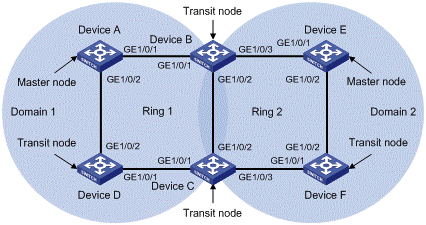
Figure 1-9 Networking diagram for multi-domain intersecting ring configuration
II. Configuration considerations
First, determine the node roles on the primary ring and subring in each RRPP domain, and then perform the following configuration domain by domain on each device:
l Create RRPP domains;
l Specify the control VLAN for each domain;
l Specify the node role of each device on each RRPP ring and the ports that access the device to the RRPP rings;
l Enable the RRPP rings;
l Enable RRPP after completing the configuration of both domains.
III. Configuration procedure
1) Perform the following configuration on Device A:
<Device A> system-view
[DeviceA] interface gigabitethernet 1/0/1
[DeviceA-GigabitEthernet1/0/1] link-delay 0
[DeviceA-GigabitEthernet1/0/1] quit
[DeviceA] interface gigabitethernet 1/0/2
[DeviceA-GigabitEthernet1/0/2] link-delay 0
[DeviceA-GigabitEthernet1/0/2] quit
[Device A] rrpp domain 1
[Device A-rrpp-domain1] control-vlan 4090
[Device A-rrpp-domain1] ring 1 node-mode master primary-port gigabitethernet 1/0/1 secondary-port gigabitethernet 1/0/2 level 0
[Device A-rrpp-domain1] ring 1 enable
[Device A-rrpp-domain1] quit
[Device A] rrpp enable
2) Perform the following configuration on Device B:
<Device B> system-view
[DeviceB] interface gigabitethernet 1/0/1
[DeviceB-GigabitEthernet1/0/1] link-delay 0
[DeviceB-GigabitEthernet1/0/1] quit
[DeviceB] interface gigabitethernet 1/0/2
[DeviceB-GigabitEthernet1/0/2] link-delay 0
[DeviceB-GigabitEthernet1/0/2] quit
[DeviceB] interface gigabitethernet 1/0/3
[DeviceB-GigabitEthernet1/0/3] link-delay 0
[DeviceB-GigabitEthernet1/0/3] quit
[Device B] rrpp domain 1
[Device B-rrpp-domain1] control-vlan 4090
[Device B-rrpp-domain1] ring 1 node-mode transit primary-port gigabitethernet 1/0/1 secondary-port gigabitethernet 1/0/2 level 0
[Device B-rrpp-domain1] ring 1 enable
[Device B- rrpp-domain1] quit
[Device B] rrpp domain 2
[Device B-rrpp-domain2] control-vlan 4092
[Device B-rrpp-domain2] ring 2 node-mode transit primary-port gigabitethernet 1/0/2 secondary-port gigabitethernet 1/0/3 level 0
[Device B-rrpp-domain2] ring 2 enable
[Device B-rrpp-domain2] quit
[Device B] rrpp enable
3) Perform the following configuration on Device C:
<Device C> system-view
[DeviceC] interface gigabitethernet 1/0/1
[DeviceC-GigabitEthernet1/0/1] link-delay 0
[DeviceC-GigabitEthernet1/0/1] quit
[DeviceC] interface gigabitethernet 1/0/2
[DeviceC-GigabitEthernet1/0/2] link-delay 0
[DeviceC-GigabitEthernet1/0/2] quit
[DeviceC] interface gigabitethernet 1/0/3
[DeviceC-GigabitEthernet1/0/3] link-delay 0
[DeviceC-GigabitEthernet1/0/3] quit
[Device C] rrpp domain 1
[Device C-rrpp-domain1] control-vlan 4090
[Device C-rrpp-domain1] ring 1 node-mode transit primary-port gigabitethernet 1/0/1 secondary-port gigabitethernet 1/0/2 level 0
[Device C-rrpp-domain1] ring 1 enable
[Device C-rrpp-domain1] quit
[Device C] rrpp domain 2
[Device C-rrpp-domain2] control-vlan 4092
[Device C-rrpp-domain2] ring 2 node-mode transit primary-port gigabitethernet 1/0/3 secondary-port gigabitethernet 1/0/2 level 0
[Device C-rrpp-domain2] ring 2 enable
[Device C-rrpp-domain2] quit
[Device C] rrpp enable
4) Perform the following configuration on Device D:
<Device D> system-view
[DeviceD] interface gigabitethernet 1/0/1
[DeviceD-GigabitEthernet1/0/1] link-delay 0
[DeviceD-GigabitEthernet1/0/1] quit
[DeviceD] interface gigabitethernet 1/0/2
[DeviceD-GigabitEthernet1/0/2] link-delay 0
[DeviceD-GigabitEthernet1/0/2] quit
[Device D] rrpp domain 1
[Device D-rrpp-domain1] control-vlan 4090
[Device D-rrpp-domain1] ring 1 node-mode transit primary-port gigabitethernet 1/0/1 secondary-port gigabitethernet 1/0/2 level 0
[Device D-rrpp-domain1] ring 1 enable
[Device D-rrpp-domain1] quit
[Device D] rrpp enable
5) Perform the following configuration on Device E:
<Device E> system-view
[DeviceE] interface gigabitethernet 1/0/1
[DeviceE-GigabitEthernet1/0/1] link-delay 0
[DeviceE-GigabitEthernet1/0/1] quit
[DeviceE] interface gigabitethernet 1/0/2
[DeviceE-GigabitEthernet1/0/2] link-delay 0
[DeviceE-GigabitEthernet1/0/2] quit
[Device E] rrpp domain 2
[Device E-rrpp-domain2] control-vlan 4092
[Device E-rrpp-domain2] ring 2 node-mode master primary-port gigabitethernet 1/0/1 secondary-port gigabitethernet 1/0/2 level 0
[Device E-rrpp-domain2] ring 2 enable
[Device E-rrpp-domain2] quit
[Device E] rrpp enable
6) Perform the following configuration on Device F:
<Device F> system-view
[DeviceF] interface gigabitethernet 1/0/1
[DeviceF-GigabitEthernet1/0/1] link-delay 0
[DeviceF-GigabitEthernet1/0/1] quit
[DeviceF] interface gigabitethernet 1/0/2
[DeviceF-GigabitEthernet1/0/2] link-delay 0
[DeviceF-GigabitEthernet1/0/2] quit
[Device F] rrpp domain 2
[Device F-rrpp-domain2] control-vlan 4092
[Device F-rrpp-domain2] ring 2 node-mode transit primary-port gigabitethernet 1/0/1 secondary-port gigabitethernet 1/0/2 level 0
[Device F-rrpp-domain2] ring 2 enable
[Device F-rrpp-domain2] quit
[Device F] rrpp enable
After the configuration, you can use the display command to view RRPP configuration result.
