- Table of Contents
-
- H3C S5500-EI Series Switches Operation Manual-Release 2102(V1.01)
- 00-Preface
- 01-CLI configuration
- 02-RBAC configuration
- 03-Login management configuration
- 04-FTP and TFTP configuration
- 05-File system management configuration
- 06-Configuration file management configuration
- 07-Software upgrade configuration
- 08-Emergency shell configuration
- 09-Automatic configuration
- 10-Device management configuration
- 11-Tcl configuration
- 12-Python configuration
- 13-License management
- Related Documents
-
| Title | Size | Download |
|---|---|---|
| 14-IPv6 Configuration | 439 KB |
Chapter 1 IPv6 Basics Configuration
1.1.2 Introduction to IPv6 Address
1.1.3 Introduction to IPv6 Neighbor Discovery Protocol
1.1.5 Introduction to IPv6 DNS
1.2 IPv6 Basics Configuration Task List
1.3 Configuring Basic IPv6 Functions
1.3.1 Enabling the IPv6 Packet Forwarding Function
1.3.2 Configuring an IPv6 Unicast Address
1.4.1 Configuring a Static Neighbor Entry
1.4.2 Configuring the Maximum Number of Neighbors Dynamically Learned
1.4.3 Configuring Parameters Related to an RA Message
1.4.4 Configuring the Number of Attempts to Send an NS Message for DAD
1.5 Configuring PMTU Discovery
1.5.1 Configuring a Static PMTU for a Specified IPv6 Address
1.5.2 Configuring the Aging Time for PMTU
1.6 Configuring IPv6 TCP Properties
1.7 Configuring ICMPv6 Packet Sending
1.7.1 Configuring the Maximum ICMPv6 Error Packets Sent in an Interval
1.7.2 Enable Sending of Multicast Echo Replies
1.8.1 Configuring Static IPv6 Domain Name Resolution
1.8.2 Configuring Dynamic IPv6 Domain Name Resolution
1.9 Displaying and Maintaining IPv6 Basics Configuration
1.10 IPv6 Configuration Example
1.11 Troubleshooting IPv6 Basics Configuration
Chapter 2 Dual Stack Configuration
Chapter 3 Tunneling Configuration
3.2 Tunneling Configuration Task List
3.3 Configuring IPv6 Manual Tunnel
3.3.1 Configuration Prerequisites
3.4.1 Configuration Prerequisites
3.5.1 Configuration Prerequisites
3.6 Displaying and Maintaining Tunneling Configuration
3.7 Troubleshooting Tunneling Configuration
Chapter 1 IPv6 Basics Configuration
When configuring IPv6 basics, go to these sections for information you are interested in:
l IPv6 Basics Configuration Task List
l Configuring Basic IPv6 Functions
l Configuring IPv6 TCP Properties
l Configuring ICMPv6 Packet Sending
l Displaying and Maintaining IPv6 Basics Configuration
l Troubleshooting IPv6 Basics Configuration
& Note:
The term “router” or the router icon in this document refers to a router in a generic sense or a Layer 3 Ethernet switch running a routing protocol.
1.1 IPv6 Overview
Internet Protocol Version 6 (IPv6), also called IP next generation (IPng), was designed by the Internet Engineering Task Force (IETF) as the successor to Internet Protocol Version 4 (IPv4). The significant difference between IPv6 and IPv4 is that IPv6 increases the IP address size from 32 bits to 128 bits.This section covers the following:
l Introduction to IPv6 Address
l Introduction to IPv6 Neighbor Discovery Protocol
1.1.1 IPv6 Features
I. Header format simplification
IPv6 cuts down some IPv4 header fields or move them to the IPv6 extension headers to reduce the length of the basic IPv6 header. IPv6 uses the basic header with a fixed length, thus making IPv6 packet handling simple and improving the forwarding efficiency. Although the IPv6 address size is four times that of IPv4 addresses, the size of basic IPv6 headers is 40 bytes and is only twice that of IPv4 headers (excluding the Options field).
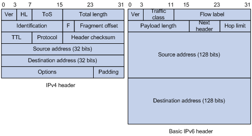
Figure 1-1 Comparison between IPv4 packet header format and basic IPv6 packet header format
II. Adequate address space
The source and destination IPv6 addresses are both 128 bits (16 bytes) long. IPv6 can provide 3.4 x 1038 addresses to completely meet the requirements of hierarchical address division as well as allocation of public and private addresses.
III. Hierarchical address structure
IPv6 adopts the hierarchical address structure to quicken route search and reduce the system source occupied by the IPv6 routing table by means of route aggregation.
IV. Automatic address configuration
To simplify the host configuration, IPv6 supports stateful and stateless address configuration.
l Stateful address configuration means that a host acquires an IPv6 address and related information from a server (for example, DHCP server).
l Stateless address configuration means that a host automatically configures an IPv6 address and related information on basis of its own link-layer address and the prefix information advertised by a router.
In addition, a host can generate a link-local address on basis of its own link-layer address and the default prefix (FE80::/64) to communicate with other hosts on the link.
V. Built-in security
IPv6 uses IPSec as its standard extension header to provide end-to-end security. This feature provides a standard for network security solutions and improves the interoperability between different IPv6 applications.
VI. QoS support
The Flow Label field in the IPv6 header allows the device to label packets in a flow and provide special handling for these packets.
VII. Enhanced neighbor discovery mechanism
The IPv6 neighbor discovery protocol is implemented through a group of Internet Control Message Protocol Version 6 (ICMPv6) messages that manages the information exchange between neighbor nodes on the same link. The group of ICMPv6 messages takes the place of Address Resolution Protocol (ARP) message, Internet Control Message Protocol version 4 (ICMPv4) router discovery message, and ICMPv4 redirection message to provide a series of other functions.
VIII. Flexible extension headers
IPv6 cancels the Options field in IPv4 packets but introduces multiple extension headers. In this way, IPv6 enhances the flexibility greatly to provide scalability for IP while improving the handling efficiency. The Options field in IPv4 packets contains 40 bytes at most, while the size of IPv6 extension headers is restricted by that of IPv6 packets.
1.1.2 Introduction to IPv6 Address
I. IPv6 address format
An IPv6 address is represented as a series of 16-bit hexadecimals, separated by colons. An IPv6 address is divided into eight groups, and the 16 bits of each group are represented by four hexadecimal numbers which are separated by colons, for example, 2001:0000:130F:0000:0000:09C0:876A:130B.
To simplify the representation of IPv6 addresses, zeros in IPv6 addresses can be handled as follows:
l Leading zeros in each group can be removed. For example, the above-mentioned address can be represented in shorter format as 2001:0:130F:0:0:9C0:876A:130B.
l If an IPv6 address contains two or more consecutive groups of zeros, they can be replaced by the double-colon :: option. For example, the above-mentioned address can be represented in the shortest format as 2001:0:130F::9C0:876A:130B.
![]() Caution:
Caution:
The double-colon :: option can be used only once in an IPv6 address. Otherwise, the device is unable to determine how many zeros double-colons represent when converting them to zeros to restore a 128-bit IPv6 address.
An IPv6 address consists of two parts: address prefix and interface ID. The address prefix and the interface ID are respectively equivalent to the network ID and the host ID in an IPv4 address.
An IPv6 address prefix is written in IPv6-address/prefix-length notation, where IPv6-address is an IPv6 address in any of the notations and prefix-length is a decimal number indicating how many bits from the utmost left of an IPv6 address are the address prefix.
II. IPv6 address classification
IPv6 addresses fall into three types: unicast address, multicast address, and anycast address.
l Unicast address: An identifier for a single interface, similar to an IPv4 unicast address. A packet sent to a unicast address is delivered to the interface identified by that address.
l Multicast address: An identifier for a set of interfaces (typically belonging to different nodes), similar to an IPv4 multicast address. A packet sent to a multicast address is delivered to all interfaces identified by that address.
l Anycast address: An identifier for a set of interfaces (typically belonging to different nodes). A packet sent to an anycast address is delivered to one of the interfaces identified by that address (the nearest one, according to the routing protocols’ measure of distance).
& Note:
There are no broadcast addresses in IPv6. Their function is superseded by multicast addresses.
The type of an IPv6 address is designated by the first several bits called format prefix. Table 1-1 lists the mappings between address types and format prefixes.
Table 1-1 Mapping between address types and format prefixes
|
Type |
Format prefix (binary) |
IPv6 prefix ID |
|
|
Unicast address |
Unassigned address |
00...0 (128 bits) |
::/128 |
|
Loopback address |
00...1 (128 bits) |
::1/128 |
|
|
Link-local address |
1111111010 |
FE80::/10 |
|
|
Site-local address |
1111111011 |
FEC0::/10 |
|
|
Global unicast address |
other forms |
— |
|
|
Multicast address |
11111111 |
FF00::/8 |
|
|
Anycast address |
Anycast addresses are taken from unicast address space and are not syntactically distinguishable from unicast addresses. |
||
III. Unicast address
There are several forms of unicast address assignment in IPv6, including aggregatable global unicast address, link-local address, and site-local address.
l The aggregatable global unicast address, equivalent to an IPv4 public address, is provided for network service providers. The type of address allows efficient route prefix aggregation to restrict the number of global routing entries.
l The link-local address is used for communication between link-local nodes in neighbor discovery and stateless autoconfiguration. Routers must not forward any packets with link-local source or destination addresses to other links.
l IPv6 unicast site-local addresses are similar to private IPv4 addresses. Routers must not forward any packets with site-local source or destination addresses outside of the site (equivalent to a private network).
l Loopback address: The unicast address 0:0:0:0:0:0:0:1 (represented in the shortest format as ::1) is called the loopback address and may never be assigned to any physical interface. Like the loopback address in IPv4, it may be used by a node to send an IPv6 packet to itself.
l Unassigned address: The unicast address "::” is called the unassigned address and may not be assigned to any node. Before acquiring a valid IPv6 address, a node may fill this address in the source address field of an IPv6 packet, but may not use it as a destination IPv6 address.
IV. Multicast address
IPv6 multicast addresses listed in Table 1-2 are reserved for special purpose.
Table 1-2 Reserved IPv6 multicast addresses
|
Address |
Application |
|
FF01::1 |
Node-local scope all-nodes multicast address |
|
FF02::1 |
Link-local scope all-nodes multicast address |
|
FF01::2 |
Node-local scope all-routers multicast address |
|
FF02::2 |
Link-local scope all-routers multicast address |
|
FF05::2 |
Site-local scope all-routers multicast address |
Besides, there is another type of multicast address: solicited-node address. A solicited-node multicast address is used to acquire the link-layer addresses of neighbor nodes on the same link and is also used for duplicate address detection (DAD). Each IPv6 unicast or anycast address has one corresponding solicited-node address. The format of a solicited-node multicast address is as follows:
FF02:0:0:0:0:1:FFXX:XXXX
Where, FF02:0:0:0:0:1 FF is permanent and consists of 104 bits, and XX:XXXX is the last 24 bits of an IPv6 unicast or anycast address.
V. Interface identifier in IEEE EUI-64 format
Interface identifiers in IPv6 unicast addresses are used to identify interfaces on a link and they are required to be unique on that link. Interface identifiers in IPv6 unicast addresses are currently required to be 64 bits long. An interface identifier in IEEE EUI-64 format is derived from the link-layer address of that interface. Interface identifiers in IPv6 addresses are 64 bits long, while MAC addresses are 48 bits long. Therefore, the hexadecimal number FFFE needs to be inserted in the middle of MAC addresses (behind the 24 high-order bits). To ensure the interface identifier obtained from a MAC address is unique, it is necessary to set the universal/local (U/L) bit (the seventh high-order bit) to “1”. Thus, an interface identifier in IEEE EUI-64 format is obtained.
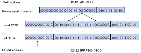
Figure 1-2 Convert a MAC address into an EUI-64 interface identifier
1.1.3 Introduction to IPv6 Neighbor Discovery Protocol
IPv6 Neighbor Discovery Protocol (NDP) uses five types of ICMPv6 messages to implement the following functions:
l Neighbor reachability detection
l Router/prefix discovery and address autoconfiguration
Table 1-3 lists the types and functions of ICMPv6 messages used by the NDP.
Table 1-3 Types and functions of ICMPv6 messages
|
ICMPv6 message |
Number |
Function |
|
Neighbor solicitation (NS) message |
135 |
Used to acquire the link-layer address of a neighbor |
|
Used to verify whether the neighbor is reachable |
||
|
Used to perform a duplicate address detection |
||
|
Neighbor advertisement (NA) message |
136 |
Used to respond to an NS message |
|
When the link layer changes, the local node initiates an NA message to notify neighbor nodes of the node information change. |
||
|
Router solicitation (RS) message |
133 |
After started, a node sends an RS message to request the router for an address prefix and other configuration information for the purpose of autoconfiguration. |
|
Router advertisement (RA) message |
134 |
Used to respond to an RS message |
|
With the RA message suppression disabled, the router regularly sends an RA message containing information such as prefix information options and flag bits. |
||
|
Redirect message |
137 |
When a certain condition is satisfied, the default gateway sends a redirect message to the source host so that the host can reselect a correct next hop router to forward packets. |
The NDP mainly provides the following functions:
I. Address resolution
Similar to the ARP function in IPv4, a node acquires the link-layer addresses of neighbor nodes on the same link through NS and NA messages. Figure 1-3 shows how node A acquires the link-layer address of node B.
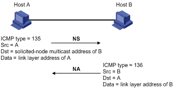
The address resolution procedure is as follows:
1) Node A multicasts an NS message. The source address of the NS message is the IPv6 address of an interface of node A and the destination address is the solicited-node multicast address of node B. The NS message contains the link-layer address of node A.
2) After receiving the NS message, node B judges whether the destination address of the packet corresponds to the solicited-node multicast address. If yes, node B can learn the link-layer address of node A, and unicasts an NA message containing its link-layer address.
3) Node A acquires the link-layer address of node B from the NA message.
II. Neighbor reachability detection
After node A acquires the link-layer address of its neighbor node B, node A can verify whether node B is reachable according to NS and NA messages.
1) Node A sends an NS message whose destination address is the IPv6 address of node B.
2) If node A receives an NA message from node B, node A considers that node B is reachable. Otherwise, node B is unreachable.
III. Duplicate address detection
After node A acquires an IPv6 address, it will perform duplicate address detection (DAD) to determine whether the address is being used by other nodes (similar to the gratuitous ARP function of IPv4). DAD is accomplished through NS and NA messages. Figure 1-3 shows the DAD procedure.
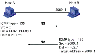
Figure 1-4 Duplicate address detection
The DAD procedure is as follows:
1) Node A sends an NS message whose source address is the unassigned address :: and destination address is the corresponding solicited-node multicast address of the IPv6 address to be detected. The NS message contains the IPv6 address.
2) If node B uses this IPv6 address, node B returns an NA message. The NA message contains the IPv6 address of node B.
3) Node A learns that the IPv6 address is being used by node B after receiving the NA message from node B. Otherwise, node B is not using the IPv6 address and node A can use it.
IV. Router/prefix discovery and address autoconfiguration
Router/prefix discovery means that a node locates the neighboring routers, and learns the prefix of the network where the host is located, and other configuration parameters from the received RA message.
Stateless address autoconfiguration means that a node automatically configures an IPv6 address according to the information obtained through router/prefix discovery.
The router/prefix discovery is implemented through RS and RA messages. The router/prefix discovery procedure is as follows:
1) After started, a node sends an RS message to request the router for the address prefix and other configuration information for the purpose of autoconfiguration.
2) The router returns an RA message containing information such as prefix information option. (The router also regularly sends an RA message.)
& Note:
l In addition to an address prefix, the prefix information option also contains the preferred lifetime and valid lifetime of the address prefix. After receiving a periodic RA message, the node updates the preferred lifetime and valid lifetime of the address prefix accordingly.
l An automatically generated address is applicable within the valid lifetime and will be removed when the valid lifetime times out.
V. Redirection
When a host is started, its routing table may contain only the default route to the gateway. When certain conditions are satisfied, the gateway sends an ICMPv6 redirect message to the source host so that the host can select a better next hop to forward packets (similar to the ICMP redirection function in IPv4).
The gateway will send an IPv6 ICMP redirect message when the following conditions are satisfied:
l The receiving interface is the forwarding interface.
l The selected route itself is not created or modified by an IPv6 ICMP redirect message.
l The selected route is not the default route.
l The forwarded IPv6 packet does not contain any routing header.
1.1.4 IPv6 PMTU Discovery
The links that a packet passes from the source to the destination may have different MTUs. In IPv6, when the packet size exceeds the link MTU, the packet will be fragmented at the source end so as to reduce the processing pressure of the forwarding device and utilize network resources rationally.
The path MTU (PMTU) discovery mechanism is to find the minimum MTU of all links in the path from the source to the destination. Figure 1-5 shows the working procedure of the PMTU discovery.
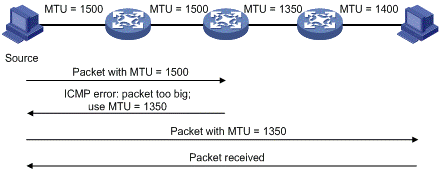
Figure 1-5 Working procedure of the PMTU discovery
The working procedure of the PMTU discovery is as follows:
1) The source host uses its MTU to fragment packets and then sends them to the destination host.
2) If the MTU supported by the forwarding interface is less than the packet size, the forwarding device will discard the packet and return an ICMPv6 error packet containing the interface MTU to the source host.
3) After receiving the ICMPv6 error packet, the source host uses the returned MTU to fragment the packet again and then sends it.
4) Step 2 to step 3 are repeated until the destination host receives the packet. In this way, the minimum MTU of all links in the path from the source host to the destination host is determined.
1.1.5 Introduction to IPv6 DNS
In the IPv6 network, a Domain Name System (DNS) supporting IPv6 converts domain names into IPv6 addresses, instead of IPv4 addresses.
However, just like an IPv4 DNS, an IPv6 DNS also covers static domain name resolution and dynamic domain name resolution. The function and implementation of these two types of domain name resolution are the same as those of an IPv4 DNS. For details, refer to DNS Configuration.
Usually, the DNS server connecting IPv4 and IPv6 networks not only contain A records (IPv4 addresses), but also AAAA records (IPv6 addresses). The DNS server can convert domain names into IPv4 addresses or IPv6 addresses. In this way, the DNS server implements the functions of both IPv6 DNS and IPv4 DNS.
1.1.6 Protocols and Standards
Protocols and standards related to IPv6 include:
l RFC 1881: IPv6 Address Allocation Management
l RFC 1887: An Architecture for IPv6 Unicast Address Allocation
l RFC 1981: Path MTU Discovery for IP version 6
l RFC 2375: IPv6 Multicast Address Assignments
l RFC 2460: Internet Protocol, Version 6 (IPv6) Specification.
l RFC 2461: Neighbor Discovery for IP Version 6 (IPv6)
l RFC 2462: IPv6 Stateless Address Autoconfiguration
l RFC 2463: Internet Control Message Protocol (ICMPv6) for the Internet Protocol Version 6 (IPv6) Specification
l RFC 2464: Transmission of IPv6 Packets over Ethernet Networks
l RFC 2526: Reserved IPv6 Subnet Anycast Addresses
l RFC 3307: Allocation Guidelines for IPv6 Multicast Addresses
l RFC 3513: Internet Protocol Version 6 (IPv6) Addressing Architecture
l RFC 3596: DNS Extensions to Support IP Version 6
1.2 IPv6 Basics Configuration Task List
Complete the following tasks to perform IPv6 basics configuration:
|
Task |
Remarks |
|
Required |
|
|
Optional |
|
|
Optional |
|
|
Optional |
|
|
Optional |
|
|
Optional |
1.3 Configuring Basic IPv6 Functions
1.3.1 Enabling the IPv6 Packet Forwarding Function
Before IPv6-related configurations, you must enable the IPv6 packet forwarding function. Otherwise, an interface cannot forward IPv6 packets even if an IPv6 address is configured, resulting in communication failures in the IPv6 network.
Follow these steps to enable the IPv6 packet forwarding function:
|
To do... |
Use the command... |
Remarks |
|
Enter system view |
system-view |
— |
|
Enable the IPv6 packet forwarding function |
ipv6 |
Required Disabled by default. |
1.3.2 Configuring an IPv6 Unicast Address
IPv6 site-local addresses and aggregatable global unicast addresses can be configured in the following ways:
l EUI-64 format: When the EUI-64 format is adopted to form IPv6 addresses, the IPv6 address prefix of an interface is the configured prefix and the interface identifier is derived from the link-layer address of the interface.
l Manual configuration: IPv6 site-local addresses or aggregatable global unicast addresses are configured manually.
IPv6 link-local addresses can be configured in either of the following ways:
l Automatic generation: The device automatically generates a link-local address for an interface according to the link-local address prefix (FE80::/64) and the link-layer address of the interface.
l Manual assignment: IPv6 link-local addresses can be assigned manually.
Follow these steps to configure an IPv6 unicast address:
|
To do... |
Use the command... |
Remarks |
|
|
Enter system view |
system-view |
— |
|
|
Enter interface view |
interface interface-type interface-number |
— |
|
|
Configure an IPv6 aggregatable global unicast address or site-local address |
Manually assign an IPv6 address |
ipv6 address { ipv6-address prefix-length | ipv6-address/prefix-length } |
Required to use either command. By default, no site-local address or aggregatable global unicast address is configured for an interface. |
|
Adopt the EUI-64 format to form an IPv6 address |
ipv6 address ipv6-address/prefix-length eui-64 |
||
|
Configure an IPv6 link-local address |
Automatically generate a link-local address |
ipv6 address auto link-local |
Optional By default, after an IPv6 site-local address or aggregatable global unicast address is configured for an interface, a link-local address will be generated automatically. |
|
Manually assign a link-local address for an interface |
ipv6 address ipv6-address link-local |
||
& Note:
l After an IPv6 site-local address or aggregatable global unicast address is configured for an interface, a link-local address will be generated automatically. The automatically generated link-local address is the same as the one generated by using the ipv6 address auto link-local command. If a link-local address is manually assigned to an interface, this link-local address takes effect. If the manually assigned link-local address is removed, the automatically generated link-local address takes effect.
l The manual assignment takes precedence over the automatic generation. That is, if you first adopt the automatic generation and then the manual assignment, the manually assigned link-local address will overwrite the automatically generated one. If you first adopt the manual assignment and then the automatic generation, the automatically generated link-local address will not take effect and the link-local address of an interface is still the manually assigned one. If you delete the manually assigned address, the automatically generated link-local address is validated.
l You need to execute the ipv6 address auto link-local command before the undo ipv6 address auto link-local command. However, if an IPv6 site-local address or aggregatable global unicast address is already configured for an interface, the interface still has a link-local address because the system automatically generates one for the interface. If no IPv6 site-local address or aggregatable global unicast address is configured, the interface has no link-local address.
1.4 Configuring IPv6 NDP
1.4.1 Configuring a Static Neighbor Entry
The IPv6 address of a neighbor node can be resolved into a link-layer address dynamically through NS and NA messages or through a manually configured neighbor entry.
The device uniquely identifies a static neighbor entry according to the IPv6 address and the layer 3 interface ID. Currently, there are two configuration methods:
l Configure an IPv6 address and link-layer address for a Layer 3 interface.
l Configure an IPv6 address and link-layer address for a port in a VLAN.
Follow these steps to configure a static neighbor entry:
|
To do... |
Use the command... |
Remarks |
|
Enter system view |
system-view |
— |
|
Configure a static neighbor entry |
ipv6 neighbor ipv6-address mac-address { vlan-id port-type port-number | interface interface-type interface-number } |
Required |
![]() Caution:
Caution:
You can adopt either of the two methods above to configure a static neighbor entry for a VLAN interface.
l After a static neighbor entry is configured by using the first method, the device needs to resolve the corresponding Layer 2 port information of the VLAN interface.
l If you adopt the second method to configure a static neighbor entry, you should ensure that the corresponding VLAN interface exists and that the layer 2 port specified by port-type port-number belongs to the VLAN specified by vlan-id. After a static neighbor entry is configured, the device relates the VLAN interface to an IPv6 address to uniquely identify a static neighbor entry.
1.4.2 Configuring the Maximum Number of Neighbors Dynamically Learned
The device can dynamically acquire the link-layer address of a neighbor node and add it into the neighbor table through NS and NA messages. Too large a neighbor table from which neighbor entries can be dynamically acquired may lead to the forwarding performance degradation of the device. Therefore, you can restrict the size of the neighbor table by setting the maximum number of neighbors that an interface can dynamically learn. When the number of dynamically learned neighbors reaches the threshold, the interface will stop learning neighbor information.
Follow these steps to configure the maximum number of neighbors dynamically learned:
|
To do… |
Use the command… |
Remarks |
|
Enter system view |
system-view |
— |
|
Enter interface view |
interface interface-type interface-number |
— |
|
Configure the maximum number of neighbors dynamically learned by an interface |
ipv6 neighbors max-learning-num number |
Optional |
1.4.3 Configuring Parameters Related to an RA Message
You can configure whether the interface sends an RA message, the interval for sending RA messages, and parameters in RA messages. After receiving an RA message, a host can use these parameters to perform corresponding operations. Table 1-4 lists the configurable parameters in an RA message and their descriptions.
Table 1-4 Parameters in an RA message and their descriptions
|
Parameters |
Description |
|
Cur hop limit |
When sending an IPv6 packet, a host uses the value of this parameter to fill the Cur Hop Limit field in IPv6 headers. Meanwhile, the value of this parameter is equal to the value of the Cur Hop Limit field in response messages of the device. |
|
Prefix information options |
After receiving the prefix information advertised by the device, the hosts on the same link can perform stateless autoconfiguration operations. |
|
M flag |
This field determines whether hosts use the stateful autoconfiguration to acquire IPv6 addresses. If the M flag is set to 1, hosts use the stateful autoconfiguration to acquire IPv6 addresses. Otherwise, hosts use the stateless autoconfiguration to acquire IPv6 addresses, that is, hosts configure IPv6 addresses according to their own link-layer addresses and the prefix information issued by the router. |
|
O flag |
This field determines whether hosts use the stateful autoconfiguration to acquire information other than IPv6 addresses. If the O flag is set to 1, hosts use the stateful autoconfiguration (for example, DHCP server) to acquire information other than IPv6 addresses. Otherwise, hosts use the stateless autoconfiguration to acquire information other than IPv6 addresses. |
|
Router lifetime |
This field is used to set the lifetime of the router that sends RA messages to serve as the default router of hosts. According to the router lifetime in the received RA messages, hosts determine whether the router sending RA messages can serve as the default router of hosts. |
|
Retrans timer |
If the device fails to receive a response message within the specified time after sending an NS message, the device will retransmit it. |
|
Reachable time |
After the neighbor reachability detection shows that a neighbor is reachable, the device considers the neighbor is reachable within the reachable time. If the device needs to send a packet to a neighbor after the reachable time expires, the device will again confirm whether the neighbor is reachable. |
& Note:
The values of the Retrans Timer field and the Reachable Time field configured for an interface are sent to hosts via RA messages. Furthermore, this interface sends NS messages at intervals of Retrans Timer and considers a neighbor reachable within the time of Reachable Time.
Follow these steps to configure parameters related to an RA message:
|
To do… |
Use the command… |
Remarks |
|
Enter system view |
system-view |
— |
|
Configure the current hop limit |
ipv6 nd hop-limit value |
Optional 64 by default. |
|
Enter interface view |
interface interface-type interface-number |
— |
|
Disable the RA message suppression |
undo ipv6 nd ra halt |
Optional By default, RA messages are suppressed. |
|
Configure the maximum and minimum intervals for sending RA messages |
ipv6 nd ra interval max-interval-value min-interval-value |
Optional By default, the maximum interval for sending RA messages is 600 seconds, and the minimum interval is 200 seconds. The device sends RA messages at intervals of a random value between the maximum interval and the minimum interval. The minimum interval should be less than or equal to 0.75 times the maximum interval. |
|
Configure the prefix information options in RA messages |
ipv6 nd ra prefix { ipv6-address prefix-length | ipv6-address/prefix-length } valid-lifetime preferred-lifetime [ no-autoconfig [ off-link ]* |
Optional By default, no prefix information is configured in RA messages and the IPv6 address of the interface sending RA messages is used as the prefix information. |
|
Set the M flag bit to 1 |
ipv6 nd autoconfig managed-address-flag |
Optional By default, the M flag bit is set to 0, that is, hosts acquire IPv6 addresses through stateless autoconfiguration. |
|
Set the O flag bit to 1. |
ipv6 nd autoconfig other-flag |
Optional By default, the O flag bit is set to 0, that is, hosts acquire other information through stateless autoconfiguration. |
|
Configure the router lifetime in RA messages |
ipv6 nd ra router-lifetime value |
Optional 1,800 seconds by default. |
|
Set the retrans timer |
ipv6 nd ns retrans-timer value |
Optional By default, the local interface sends NS messages at intervals of 1,000 milliseconds and the Retrans Timer field in RA messages sent by the local interface is equal to 0. |
|
Set the reachable time |
ipv6 nd nud reachable-time value |
Optional By default, the neighbor reachable time on the local interface is 30,000 milliseconds and the Reachable Timer field in RA messages is 0. |
![]() Caution:
Caution:
The maximum interval for sending RA messages should be less than or equal to the router lifetime in RA messages.
1.4.4 Configuring the Number of Attempts to Send an NS Message for DAD
An interface sends a neighbor solicitation (NS) message for DAD after acquiring an IPv6 address. If the interface does not receive a response within a specified time (determined by the ipv6 nd ns retrans-timer command), it continues to send an NS message. If it still does not receive a response after the number of attempts to send an NS message reaches the maximum, the acquired address is considered available.
Follow these steps to configure the attempts to send an NS message for DAD:
|
To do… |
Use the command… |
Remarks |
|
Enter system view |
system-view |
— |
|
Enter interface view |
interface interface-type interface-number |
— |
|
Configure the number of attempts to send an NS message for DAD |
ipv6 nd dad attempts value |
Optional 1 by default. When the value argument is set to 0, DAD is disabled. |
1.5 Configuring PMTU Discovery
1.5.1 Configuring a Static PMTU for a Specified IPv6 Address
You can configure a static PMTU for a specified destination IPv6 address. When a source host sends packets through an interface, it compares the interface MTU with the static PMTU of the specified destination IPv6 address. If the packet size is larger than the smaller one between the two values, the host fragments the packet according to the smaller value.
Follow these steps to configure a static PMTU for a specified address:
|
To do… |
Use the command… |
Remarks |
|
Enter system view |
system-view |
— |
|
Configure a static PMTU for a specified IPv6 address |
ipv6 pathmtu ipv6-address [ value ] |
Required By default, no static PMTU is configured. |
1.5.2 Configuring the Aging Time for PMTU
After the MTU of the path from the source host to the destination host is dynamically determined (refer to IPv6 PMTU Discovery), the source host sends subsequent packets to the destination host on basis of this MTU. After the aging time expires, the dynamically determined PMTU is removed and the source host re-determines an MTU to send packets through the PMTU mechanism.
The aging time is invalid for static PMTU.
Follow these steps to configure the aging time for PMTU:
|
To do… |
Use the command… |
Remarks |
|
Enter system view |
system-view |
— |
|
Configure aging time for PMTU |
ipv6 pathmtu age age-time |
Optional 10 minutes by default. |
1.6 Configuring IPv6 TCP Properties
The IPv6 TCP properties you can configure include:
l synwait timer: When a SYN packet is sent, the synwait timer is triggered. If no response packet is received before the synwait timer expires, the IPv6 TCP connection establishment fails.
l finwait timer: When the IPv6 TCP connection status is FIN_WAIT_2, the finwait timer is triggered. If no packet is received before the finwait timer expires, the IPv6 TCP connection is terminated. If a FIN packet is received, the IPv6 TCP connection status becomes TIME_WAIT. If other packets are received, the finwait timer is reset from the last received packet and the connection is terminated after the finwait timer expires.
l Size of the IPv6 TCP sending/receiving buffer.
Follow these steps to configure IPv6 TCP properties:
|
To do… |
Use the command… |
Remarks |
|
Enter system view |
system-view |
— |
|
Set the finwait timer of IPv6 TCP packets |
tcp ipv6 timer fin-timeout wait-time |
Optional 675 seconds by default. |
|
Set the synwait timer of IPv6 TCP packets |
tcp ipv6 timer syn-timeout wait-time |
Optional 75 seconds by default. |
|
Set the size of the IPv6 TCP sending/receiving buffer |
tcp ipv6 window size |
Optional 8 KB by default. |
1.7 Configuring ICMPv6 Packet Sending
1.7.1 Configuring the Maximum ICMPv6 Error Packets Sent in an Interval
If too many ICMPv6 error packets are sent within a short time in a network, network congestion may occur. To avoid network congestion, you can control the maximum number of ICMPv6 error packets sent within a specified time, currently by adopting the token bucket algorithm.
You can set the capacity of a token bucket, namely, the number of tokens in the bucket. In addition, you can set the update period of the token bucket, namely, the interval for updating the number of tokens in the token bucket to the configured capacity. One token allows one ICMPv6 error packet to be sent. Each time an ICMPv6 error packet is sent, the number of tokens in a token bucket decreases by 1. If the number of ICMPv6 error packets successively sent exceeds the capacity of the token bucket, subsequent ICMPv6 error packets cannot be sent out until the number of tokens in the token bucket is updated and new tokens are added to the bucket.
Follow these steps to configure the capacity and update period of the token bucket:
|
To do… |
Use the command… |
Remarks |
|
Enter system view |
system-view |
— |
|
Configure the capacity and update period of the token bucket |
ipv6 icmp-error { bucket bucket-size | ratelimit interval } * |
Optional By default, the capacity of a token bucket is 10 and the update period is 100 milliseconds. That is, at most 10 IPv6 ICMP error packets can be sent within these 100 milliseconds. The update period “0” indicates that the number of ICMPv6 error packets sent is not restricted. |
1.7.2 Enable Sending of Multicast Echo Replies
If hosts are capable of relying multicast echo requests, Host A can attack Host B by sending an echo request with the source being Host B to a multicast address, then all the hosts in the multicast group will send echo replies to Host B. Therefore, a device is disabled from replying multicast echo requests by default.
Follow these steps to enable sending of multicast echo replies:
|
To do… |
Use the command… |
Remarks |
|
Enter system view |
system-view |
— |
|
Enable sending of multicast echo replies |
ipv6 icmpv6 multicast-echo-reply enable |
Not enabled by default. |
1.8 Configuring IPv6 DNS
1.8.1 Configuring Static IPv6 Domain Name Resolution
Configuring static IPv6 domain name resolution is to establish the mapping between host name and IPv6 address. When applying such applications as Telnet, you can directly use a host name and the system will resolve the host name into an IPv6 address. Each host name can correspond to only one IPv6 address.
Follow these steps to configure static IPv6 domain name resolution:
|
To do… |
Use the command… |
Remarks |
|
Enter system view |
system-view |
— |
|
Configure a host name and the corresponding IPv6 address |
ipv6 host hostname ipv6-address |
Required |
1.8.2 Configuring Dynamic IPv6 Domain Name Resolution
If you want to use the dynamic domain name function, you can use the following command to enable the dynamic domain name resolution function. In addition, you should configure a DNS server so that a query request message can be sent to the correct server for resolution. The system can support at most six DNS servers.
You can configure a DNS suffix so that you only need to enter some fields of a domain name and the system can automatically add the preset suffix for address resolution. The system can support at most 10 DNS suffixes.
Follow these steps to configure dynamic IPv6 domain name resolution:
|
To do… |
Use the command… |
Remarks |
|
Enter system view |
system-view |
— |
|
Enable the dynamic domain name resolution function |
dns resolve |
Required Disabled by default. |
|
Configure an IPv6 DNS server |
dns server ipv6 ipv6-address [ interface-type interface-number ] |
Required If the IPv6 address of the DNS server is a link-local address, you need to specify a value for interface-type and interface-number. |
|
Configure the DNS suffix. |
dns domain domain-name |
Required By default, no DN suffix is configured, that is, the domain name is resolved according to the input information. |
& Note:
The dns resolve and dns domain commands are the same as those of IPv4 DNS. For details about the commands, refer to DNS Commands.
1.9 Displaying and Maintaining IPv6 Basics Configuration
|
To do… |
Use the command… |
Remarks |
|
Display DNS suffix information |
display dns domain [ dynamic ] |
Available in any view |
|
Display IPv6 dynamic domain name cache information. |
display dns ipv6 dynamic-host |
|
|
Display IPv6 DNS server information |
display dns ipv6 server [ dynamic ] |
|
|
Display the IPv6 FIB entries |
display ipv6 fib [ ipv6-address ] |
|
|
Display the mappings between host names and IPv6 addresses in the static DNS database. |
display ipv6 host |
|
|
Display the IPv6 information of an interface |
display ipv6 interface [ brief ] [ interface-type [ interface-number ] ] |
|
|
Display neighbor information |
display ipv6 neighbors { ipv6-address | all | dynamic | interface interface-type interface-number | static | vlan vlan-id } [ | { begin | exclude | include } string ] |
|
|
Display the total number of neighbor entries satisfying the specified conditions |
display ipv6 neighbors { all | dynamic | interface interface-type interface-number | static | vlan vlan-id } count |
Available in any view |
|
Display the PMTU information of an IPv6 address |
display ipv6 pathmtu { ipv6-address | all | dynamic | static } |
|
|
Display information related to a specified socket |
display ipv6 socket [ socktype socket-type ] [ task-id socket-id ] |
|
|
Display the statistics of IPv6 packets and ICMPv6 packets |
display ipv6 statistics |
|
|
Display the IPv6 TCP connection statistics |
display tcp ipv6 statistics |
|
|
Display the IPv6 TCP connection status |
display tcp ipv6 status |
|
|
Display the IPv6 UDP connection statistics |
display udp ipv6 statistics |
|
|
Clear IPv6 dynamic domain name cache information |
reset dns ipv6 dynamic-host |
Available in user view |
|
Clear IPv6 neighbor information |
reset ipv6 neighbors { all | dynamic | interface interface-type interface-number | static } |
|
|
Clear the corresponding PMTU |
reset ipv6 pathmtu { all | static | dynamic} |
|
|
Clear the statistics of IPv6 and ICMPv6 packets |
reset ipv6 statistics |
|
|
Clear all IPv6 TCP connection statistics |
reset tcp ipv6 statistics |
|
|
Clear the statistics of all IPv6 UDP packets |
reset udp ipv6 statistics |
& Note:
The display dns domain command is the same as the one of IPv4 DNS. For details about the commands, refer to DNS Commands.
1.10 IPv6 Configuration Example
I. Network requirements
Two switches are directly connected through two Ethernet ports. The Ethernet ports belong to VLAN 2. Configure different types of IPv6 addresses for VLAN-interface 2 respectively on Switch A and Switch B to verify the connectivity between two switches. The IPv6 prefix in the EUI-64 format is 2001::/64. Specify the aggregatable global unicast address of Switch A as 3001::1/64, and the aggregatable global unicast address of Switch B as 3001::2/64.
II. Network diagram
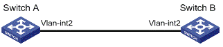
Figure 1-6 Network diagram for IPv6 address configuration
III. Configuration procedure
l Configuration on Switch A
# Enable the IPv6 packet forwarding function.
<SwitchA> system-view
[SwitchA] ipv6
# Configure VLAN-interface 2 to automatically generate a link-local address.
[SwitchA] interface vlan-interface 2
[SwitchA-Vlan-interface2] ipv6 address auto link-local
# Configure an EUI-64 address for VLAN-interface 2.
[SwitchA-Vlan-interface2] ipv6 address 2001::/64 eui-64
# Specify an aggregatable global unicast address for VLAN-interface 2.
[SwitchA-Vlan-interface2] ipv6 address 3001::1/64
# Allow VLAN-interface 2 to advertise RA messages.
[SwitchA-Vlan-interface2] undo ipv6 nd ra halt
l Configuration on Switch B
# Enable the IPv6 packet forwarding function.
<SwitchB> system-view
[SwitchB] ipv6
# Configure VLAN-interface 2 to automatically generate a link-local address.
[SwitchB] interface vlan-interface 2
[SwitchB-Vlan-interface2] ipv6 address auto link-local
# Configure an EUI-64 address for VLAN-interface 2.
[SwitchB-Vlan-interface2] ipv6 address 2001::/64 eui-64
# Configure an aggregatable global unicast address for VLAN-interface 2.
[SwitchB-Vlan-interface2] ipv6 address 3001::2/64
IV. Verification
# Display the IPv6 information of the interface on Switch A.
[SwitchA-Vlan-interface2] display ipv6 interface vlan-interface 2
Vlan-interface2 current state :UP
Line protocol current state :UP
IPv6 is enabled, link-local address is FE80::20F:E2FF:FE49:8048
Global unicast address(es):
2001::20F:E2FF:FE49:8048, subnet is 2001::/64
3001::1, subnet is 3001::/64
Joined group address(es):
FF02::1:FF00:1
FF02::1:FF49:8048
FF02::2
FF02::1
MTU is 1500 bytes
ND DAD is enabled, number of DAD attempts: 1
ND reachable time is 30000 milliseconds
ND retransmit interval is 1000 milliseconds
Hosts use stateless autoconfig for addresses
# Display the IPv6 information of the interface on Switch B.
[SwitchB-Vlan-interface2] display ipv6 interface vlan-interface 2
Vlan-interface2 current state :UP
Line protocol current state :UP
IPv6 is enabled, link-local address is FE80::20F:E2FF:FE00:1
Global unicast address(es):
2001::20F:E2FF:FE00:1, subnet is 2001::/64
3001::2, subnet is 3001::/64
Joined group address(es):
FF02::1:FF00:2
FF02::1:FF00:1
FF02::2
FF02::1
MTU is 1500 bytes
ND DAD is enabled, number of DAD attempts: 1
ND reachable time is 30000 milliseconds
ND retransmit interval is 1000 milliseconds
Hosts use stateless autoconfig for addresses
# From Switch A, ping the link-local address, EUI-64 address, and aggregatable global unicast address respectively. If the configurations are correct, the three types of IPv6 addresses above can be pinged.
![]() Caution:
Caution:
When you ping a link-local address, you should use the “–i” parameter to specify an interface for the link-local address.
[SwitchA-Vlan-interface2] ping ipv6 FE80::20F:E2FF:FE00:1 -i vlan-interface2
PING FE80::20F:E2FF:FE00:1 : 56 data bytes, press CTRL_C to break
Reply from FE80::20F:E2FF:FE00:1
bytes=56 Sequence=1 hop limit=255 time = 80 ms
Reply from FE80::20F:E2FF:FE00:1
bytes=56 Sequence=2 hop limit=255 time = 60 ms
Reply from FE80::20F:E2FF:FE00:1
bytes=56 Sequence=3 hop limit=255 time = 60 ms
Reply from FE80::20F:E2FF:FE00:1
bytes=56 Sequence=4 hop limit=255 time = 70 ms
Reply from FE80::20F:E2FF:FE00:1
bytes=56 Sequence=5 hop limit=255 time = 60 ms
--- FE80::20F:E2FF:FE00:1 ping statistics ---
5 packet(s) transmitted
5 packet(s) received
0.00% packet loss
round-trip min/avg/max = 60/66/80 ms
[SwitchA-Vlan-interface2] ping ipv6 2001::20F:E2FF:FE00:1
PING 2001::20F:E2FF:FE00:1 : 56 data bytes, press CTRL_C to break
Reply from 2001::20F:E2FF:FE00:1
bytes=56 Sequence=1 hop limit=255 time = 40 ms
Reply from 2001::20F:E2FF:FE00:1
bytes=56 Sequence=2 hop limit=255 time = 70 ms
Reply from 2001::20F:E2FF:FE00:1
bytes=56 Sequence=3 hop limit=255 time = 60 ms
Reply from 2001::20F:E2FF:FE00:1
bytes=56 Sequence=4 hop limit=255 time = 60 ms
Reply from 2001::20F:E2FF:FE00:1
bytes=56 Sequence=5 hop limit=255 time = 60 ms
--- 2001::20F:E2FF:FE00:1 ping statistics ---
5 packet(s) transmitted
5 packet(s) received
0.00% packet loss
round-trip min/avg/max = 40/58/70 ms
[SwitchA-Vlan-interface2] ping ipv6 3001::2
PING 3001::2 : 56 data bytes, press CTRL_C to break
Reply from 3001::2
bytes=56 Sequence=1 hop limit=255 time = 50 ms
Reply from 3001::2
bytes=56 Sequence=2 hop limit=255 time = 60 ms
Reply from 3001::2
bytes=56 Sequence=3 hop limit=255 time = 60 ms
Reply from 3001::2
bytes=56 Sequence=4 hop limit=255 time = 70 ms
Reply from 3001::2
bytes=56 Sequence=5 hop limit=255 time = 60 ms
--- 3001::2 ping statistics ---
5 packet(s) transmitted
5 packet(s) received
0.00% packet loss
round-trip min/avg/max = 50/60/70 ms
1.11 Troubleshooting IPv6 Basics Configuration
I. Symptom
The peer IPv6 address cannot be pinged.
II. Solution
l Use the display current-configuration command in any view or the display this command in system view to check that the IPv6 packet forwarding function is enabled.
l Use the display ipv6 interface command in any view to check that the IPv6 address of the interface is correct and that the interface is up.
l Use the debugging ipv6 packet command in user view to enable the debugging for IPv6 packets and make judgment according to the debugging information.
Chapter 2 Dual Stack Configuration
When configuring dual stack, go to these sections for information you are interested in:
2.1 Dual Stack Overview
Dual stack is the most direct approach to making IPv6 nodes compatible with IPv4 nodes. The best way for an IPv6 node to be compatible with an IPv4 node is to maintain a complete IPv4 stack. A network node that supports both IPv4 and IPv6 is called a dual stack node. A dual stack node configured with an IPv4 address and an IPv6 address can have both IPv4 and IPv6 packets transmitted.
For an upper layer application supporting both IPv4 and IPv6, either TCP or UDP can be selected at the transport layer, while IPv6 stack is preferred at the network layer.
Figure 2-1 illustrates the IPv4/IPv6 dual stack in relation to the IPv4 stack.
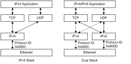
Figure 2-1 IPv4/IPv6 dual stack in relation to IPv4 stack (on Ethernet)
2.2 Configuring Dual Stack
You must enable the IPv6 packet forwarding function before dual stack. Otherwise, the device cannot forward IPv6 packets even if IPv6 addresses are configured for interfaces.
Follow these steps to configure dual stack on a gateway:
|
To do… |
Use the command… |
Remarks |
||
|
system-view |
— |
|||
|
Enable the IPv6 packet forwarding function |
ipv6 |
Required Disabled by default. |
||
|
Enter interface view |
interface interface-type interface-number |
— |
||
|
Configure an IPv4 address for the interface |
ip address ip-address { mask | mask-length } [ sub ] |
Required By default, no IP address is configured. |
||
|
Configure an IPv6 address on the interface |
Configure IPv6 global unicast address or local address |
Manually specify an IPv6 address |
ipv6 address { ipv6-address prefix-length | ipv6-address/prefix-length } |
Use either command. By default, no local address or global unicast address is configured on an interface |
|
Configure an IPv6 address in the EUI-64 format |
ipv6 address ipv6-address/prefix-length eui-64 |
|||
|
Configure IPv6 link-local address |
Automatically create an IPv6 link-local address |
ipv6 address auto link-local |
Optional By default, after you configured an IPv6 local address or global unicast address, a link local address is automatically created. |
|
|
Manually specify an IPv6 link-local address |
ipv6 address ipv6-address link-local |
|||
Chapter 3 Tunneling Configuration
When configuring tunneling, go to these sections for information you are interested in:
l Tunneling Configuration Task List
l Configuring IPv6 Manual Tunnel
l Displaying and Maintaining Tunneling Configuration
l Troubleshooting Tunneling Configuration
3.1 Introduction to Tunneling
Tunneling is an encapsulation technology, which utilizes one network transport protocol to encapsulate packets of another network transport protocol and transfer them over the network. A tunnel is a virtual point-to-point connection. In practice, the virtual interface that supports only point-to-point connections is called tunnel interface. One tunnel provides one channel to transfer encapsulated packets. Packets can be encapsulated and decapsulated at both ends of a tunnel. Tunneling refers to the whole process from data encapsulation to data transfer to data decapsulation.
& Note:
NTP-related commands are available in tunnel interface view on H3C S5500-EI series Ethernet Switches, but NTP features cannot be enabled after you execute the NTP commands. For related information about NTP, refer to NTP Configuration.
3.1.1 IPv6 over IPv4 Tunnel
I. Principle
The IPv6 over IPv4 tunneling mechanism encapsulates an IPv4 header in IPv6 data packets so that IPv6 packets can pass an IPv4 network through a tunnel to realize interworking between isolated IPv6 networks, as shown in Figure 3-1.
![]() Caution:
Caution:
The devices at both ends of an IPv6 over IPv4 tunnel must support IPv4/IPv6 dual stack.
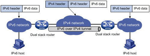
Figure 3-1 Principle of IPv6 over IPv4 tunnel
The IPv6 over IPv4 tunnel processes packets in the following way:
1) A host in the IPv6 network sends an IPv6 packet to the device at the source end of the tunnel.
2) After determining according to the routing table that the packet needs to be forwarded through the tunnel, the device at the source end of the tunnel encapsulates the IPv6 packet with an IPv4 header the and forwards it through the physical interface of the tunnel.
3) The encapsulated packet goes through the tunnel to reach the device at the destination end of the tunnel. The device at the destination end decapsulates the packet if the destination address of the encapsulated packet is the device itself.
4) The destination device forwards the packet according to the destination address in the decapsulated IPv6 packet. If the destination address is the device itself, the device forwards the IPv6 packet to the upper-layer protocol for processing.
II. Configured tunnel and automatic tunnel
An IPv6 over IPv4 tunnel can be established between hosts, between hosts and devices, and between devices. The tunnel destination needs to forward packets if the tunnel destination is not the eventual destination of the IPv6 packet.
According to the way the IPv4 address of the tunnel destination is acquired, tunnels are divided into configured tunnel and automatic tunnel.
l If the IPv4 address of the tunnel destination cannot be acquired from the destination address of the IPv6 packet, it needs to be configured manually. Such a tunnel is called a configured tunnel.
l If the IPv4 address is embedded into the IPv6 address, the IPv4 address of the tunnel destination can automatically be acquired from the destination address of the IPv6 packet. Such a tunnel is called an automatic tunnel.
III. Type
According to the way an IPv6 packet is encapsulated, IPv6 over IPv4 tunnels are divided into the following types:
l IPv6 manual tunnel
l 6to4 tunnel
l ISATAP tunnel
Among the above tunnels, the IPv6 manual tunnel is a configured tunnel, while the 6to4 tunnel, and intra-site automatic tunnel address protocol (ISATAP) tunnel are automatic tunnels.
1) IPv6 manually configured tunnel
A manually configured tunnel is a point-to-point link. One link is a separate tunnel. The IPv6 manually configured tunnels provide stable connections requiring regular secure communication between two border routers or between a border router and a host for access to remote IPv6 networks.
2) 6to4 tunnel
An automatic 6to4 tunnel is a point-to-multipoint tunnel and is used to connect multiple isolated IPv6 networks over an IPv4 network to remote IPv6 networks. The embedded IPv4 address in an IPv6 address is used to automatically acquire the destination of the tunnel. The automatic 6to4 tunnel adopts 6to4 addresses. The address format is 2002:abcd:efgh:subnet number::interface ID/64, where abcd:efgh represents the 32-bit source IPv4 address of the 6to4 tunnel, in hexadecimal notation. For example, 1.1.1.1 can be represented by 0101:0101. The tunnel destination is automatically determined by the embedded IPv4 address, which makes it easy to create a 6to4 tunnel.
Since the 16-bit subnet number of the 64-bit address prefix in 6to4 addresses can be customized and the first 48 bits in the address prefix are fixed by a permanent value and the IPv4 address of the tunnel source or destination, it is possible that IPv6 packets can be forwarded by the tunnel.
3) ISATAP tunnel
With the application of the IPv6 technology, there will be more and more IPv6 hosts in the existing IPv4 network. The ISATAP tunneling technology provides a satisfactory solution for IPv6 application. An ISATAP tunnel is a point-to-point automatic tunnel. The destination of a tunnel can automatically be acquired from the embedded IPv4 address in the destination address of an IPv6 packet. When an ISATAP tunnel is used, the destination address of an IPv6 packet and the IPv6 address of a tunnel interface both adopt special addresses: ISATAP addresses. The ISATAP address format is prefix(64bit):0:5EFE:ip-address. The ip-address is in the form of a.b.c.d or abcd:efgh, where abcd:efgh represents a 32-bit source IPv4 address. Through the embedded IPv4 address, an ISATAP tunnel can automatically be created to transfer IPv6 packets. The ISATAP tunnel is mainly used for connection between IPv6 routers or between a host and an IPv6 router over an IPv4 network.
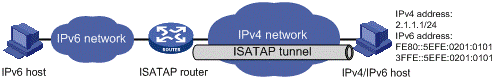
Figure 3-2 Principle of ISATAP tunnel
3.2 Tunneling Configuration Task List
Complete the following tasks to configure the tunneling feature:
|
Task |
Remarks |
|
|
Configuring IPv6 over IPv4 GRE tunnel |
Optional |
|
|
Optional |
||
|
Optional |
||
3.3 Configuring IPv6 Manual Tunnel
3.3.1 Configuration Prerequisites
IP addresses are configured for interfaces such as the VLAN interface and loopback interface on the device. These interfaces serve as the source interfaces of tunnel interfaces to ensure that the tunnel destination addresses are reachable.
3.3.2 Configuration Procedure
Follow these steps to configure an IPv6 manual tunnel:
|
To do… |
Use the command… |
Remarks |
|
|
Enter system view |
system-view |
— |
|
|
Enable IPv6 |
ipv6 |
Required By default, the IPv6 packet forwarding function is disabled. |
|
|
Create a tunnel interface and enter tunnel interface view |
interface tunnel number |
Required By default, there is no tunnel interface on the device. |
|
|
Configure an IPv6 address for the tunnel interface |
Configure a global unicast IPv6 address or a site-local address |
ipv6 address { ipv6-address prefix-length | ipv6-address/prefix-length } |
Required Use any command. By default, no IPv6 global unicast address or site-local address is configured for the tunnel interface. |
|
ipv6 address ipv6-address/prefix-length eui-64 |
|||
|
Configure a link-local IPv6 address |
ipv6 address auto link-local |
Optional A link-local address will automatically be created when an IPv6 global unicast address or site-local address is configured. |
|
|
ipv6 address ipv6-address link-local |
|||
|
Specify the IPv6 manual tunnel mode |
tunnel-protocol ipv6-ipv4 |
Required By default, the tunnel mode is manual. The same tunnel type should be configured at both ends of the tunnel. Otherwise, packet delivery will fail. |
|
|
Configure a source address or interface for the tunnel |
source { ip-address | interface-type interface-number } |
Required By default, no source address or interface is configured for the tunnel. |
|
|
Configure a destination address for the tunnel |
destination ip-address |
Required By default, no destination address is configured for the tunnel. |
|
|
Reference an aggregation group |
aggregation-group aggregation-group-id |
Required By default, no link aggregation group ID is referenced. |
|
![]() Caution:
Caution:
l After a tunnel interface is deleted, all the above features configured on the tunnel interface will be deleted.
l If the addresses of the tunnel interfaces at the two ends of a tunnel are not in the same network segment, a forwarding route through the tunnel to the peer must be configured so that the encapsulated packet can be forwarded normally. The route can be a static or dynamic route. IP addresses must be configured at both ends of the tunnel. For detailed configuration, refer to IPv4 Routing Configuration or IPv6 Routing Configuration.
l When you configure a static route, you need to configure a route to the destination address (the destination IPv6 address of the packet, instead of the IPv4 address of the tunnel destination) and set the next-hop to the tunnel interface number or network address at the local end of the tunnel. Such configurations must be performed at both ends of the tunnel.
l Before configuring dynamic routes, you must enable the dynamic routing protocol on the tunnel interfaces at both ends. For related configurations, refer to IPv6 Routing Configuration.
l Before referencing a link aggregation group on the tunnel interface to receive and send packets, make sure that the aggregation group has been configured. Otherwise, the tunnel interface will not be up to communicate.
3.3.3 Configuration Example
I. Network requirements
Two IPv6 networks are connected through an IPv6 manual tunnel between Switch A and Switch B. As shown in Figure 3-3, VLAN-interface 100 on Switch A can communicate with VLAN-interface 100 on Switch B normally via an IPv4 route.
II. Network diagram
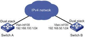
Figure 3-3 Network diagram for an IPv6 manual tunnel
III. Configuration procedure
l Configuration on Switch A
# Enable IPv6.
<SwitchA> system-view
[SwitchA] ipv6
# Configure a link aggregation group. Disable STP on the port before adding it into the link aggregation group.
[SwitchA] link-aggregation group 1 mode manual
[SwitchA] link-aggregation group 1 service-type tunnel
[SwitchA] interface GigabitEthernet 1/0/1
[SwitchA-GigabitEthernet1/0/1] stp disable
[SwitchA-GigabitEthernet1/0/1] port link-aggregation group 1
[SwitchA-GigabitEthernet1/0/1] quit
# Configure an IPv4 address for VLAN-interface 100.
[SwitchA] vlan 100
[SwitchA-vlan100] port GigabitEthernet 1/0/2
[SwitchA-vlan100] quit
[SwitchA] interface vlan-interface 100
[SwitchA-Vlan-interface100] ip address 192.168.100.1 255.255.255.0
[SwitchA-Vlan-interface100] quit
# Configure a manual IPv6 tunnel.
[SwitchA] interface tunnel 0
[SwitchA-Tunnel0] ipv6 address 3001::1/64
[SwitchA-Tunnel0] source vlan-interface 100
[SwitchA-Tunnel0] destination 192.168.50.1
[SwitchA-Tunnel0] tunnel-protocol ipv6-ipv4
# Configure the tunnel to reference link aggregation group 1 in tunnel interface view.
[SwitchA-Tunnel0] aggregation-group 1
l Configuration on Switch B
# Enable IPv6.
<SwitchB> system-view
[SwitchB] ipv6
# Configure a link aggregation group. Disable STP on the port before adding it into the link aggregation group.
[SwitchB] link-aggregation group 1 mode manual
[SwitchB] link-aggregation group 1 service-type tunnel
[SwitchB] interface GigabitEthernet 1/0/1
[SwitchB-GigabitEthernet1/0/1] stp disable
[SwitchB-GigabitEthernet1/0/1] port link-aggregation group 1
[SwitchB-GigabitEthernet1/0/1] quit
# Configure an IPv4 address for VLAN-interface 100.
[SwitchB] vlan 100
[SwitchB-vlan100] port GigabitEthernet 1/0/2
[SwitchB-vlan100] quit
[SwitchB] interface vlan-interface 100
[SwitchB-Vlan-interface100] ip address 192.168.50.1 255.255.255.0
[SwitchB-Vlan-interface100] quit
# Configure an IPv6 manual tunnel.
[SwitchB] interface tunnel 0
[SwitchB-Tunnel0] ipv6 address 3001::2/64
[SwitchB-Tunnel0] source vlan-interface 100
[SwitchB-Tunnel0] destination 192.168.100.1
[SwitchB-Tunnel0] tunnel-protocol ipv6-ipv4
# Configure the tunnel to reference link aggregation group 1 in tunnel interface view.
[SwitchB-Tunnel0] aggregation-group 1
IV. Configuration verification
After the above configurations, display the status of the tunnel interfaces on Switch A and Switch B, respectively.
[SwitchA] display ipv6 interface tunnel 0
Tunnel0 current state :UP
Line protocol current state :UP
IPv6 is enabled, link-local address is FE80::C0A8:6401
Global unicast address(es):
3001::1, subnet is 3001::/64
Joined group address(es):
FF02::1:FFA8:6401
FF02::1:FF00:1
FF02::2
FF02::1
MTU is 1500 bytes
ND reachable time is 30000 milliseconds
ND retransmit interval is 1000 milliseconds
Hosts use stateless autoconfig for addresses
[SwitchB] display ipv6 interface tunnel 0
Tunnel0 current state :UP
Line protocol current state :UP
IPv6 is enabled, link-local address is FE80::C0A8:3201
Global unicast address(es):
3001::2, subnet is 3001::/64
Joined group address(es):
FF02::1:FFA8:3201
FF02::1:FF00:2
FF02::2
FF02::1
MTU is 1500 bytes
ND reachable time is 30000 milliseconds
ND retransmit interval is 1000 milliseconds
Hosts use stateless autoconfig for addresses
# Ping the IPv6 address of the peer tunnel interface from Switch A.
[SwitchA] ping ipv6 3001::2
PING 3001::2 : 56 data bytes, press CTRL_C to break
Reply from 3001::2
bytes=56 Sequence=1 hop limit=64 time = 31 ms
Reply from 3001::2
bytes=56 Sequence=2 hop limit=64 time = 16 ms
Reply from 3001::2
bytes=56 Sequence=3 hop limit=64 time = 1 ms
Reply from 3001::2
bytes=56 Sequence=4 hop limit=64 time = 15 ms
Reply from 3001::2
bytes=56 Sequence=5 hop limit=64 time = 15 ms
--- 3001::2 ping statistics ---
5 packet(s) transmitted
5 packet(s) received
0.00% packet loss
round-trip min/avg/max = 1/15/31 ms
3.4 Configuring 6to4 Tunnel
3.4.1 Configuration Prerequisites
IP addresses are configured for interfaces such as VLAN interface and loopback interface on the device. Such an interface can serve as the source interface of the tunnel to ensure that the tunnel destination address is reachable.
3.4.2 Configuration Procedure
Follow these steps to configure a 6to4 tunnel:
|
To do… |
Use the command… |
Remarks |
|
|
Enter system view |
system-view |
— |
|
|
Enable IPv6 |
ipv6 |
Required By default, the IPv6 packet forwarding function is disabled. |
|
|
Create a tunnel interface and enter tunnel interface view |
interface tunnel number |
Required By default, there is no tunnel interface on the device. |
|
|
Configure an IPv6 address for the tunnel interface |
Configure an IPv6 global unicast address or site-local address |
ipv6 address { ipv6-address prefix-length | ipv6-address/prefix-length } |
Required. Use either command. By default, no IPv6 global unicast address or site-local address is configured for the tunnel interface. |
|
ipv6 address ipv6-address/prefix-length eui-64 |
|||
|
Configure an IPv6 link-local address |
ipv6 address auto link-local |
Optional By default, a link-local address will automatically be generated when an IPv6 global unicast address or site-local address is configured. |
|
|
ipv6 address ipv6-address link-local |
|||
|
Set a 6to4 tunnel |
tunnel-protocol ipv6-ipv4 6to4 |
Required By default, the tunnel mode is manual. The same tunnel type should be configured at both ends of the tunnel. Otherwise, packet delivery will fail. |
|
|
Configure a source address or interface for the tunnel |
source { ip-address | interface-type interface-number } |
Required By default, no source address or interface is configured for the tunnel. |
|
|
Reference a link aggregation group |
aggregation-group aggregation-group-id |
Required By default, no link aggregation group ID is referenced. |
|
![]() Caution:
Caution:
l Only one automatic tunnel can be configured at the same tunnel source.
l No destination address needs to be configured for an automatic tunnel because the destination address can automatically be obtained from the IPv4 address embedded in the IPv4-compatible IPv6 address.
l When you create a tunnel interface on a device, the slot of the tunnel interface should be that of the source interface, namely, the interface sending packets. In this way, the forwarding efficiency can be improved.
l If the addresses of the tunnel interfaces at the two ends of a tunnel are not in the same network segment, a forwarding route through the tunnel to the peer must be configured so that the encapsulated packet can be forwarded normally. You can configure static or dynamic routes. You should perform this configuration at both ends of the tunnel.
l The automatic tunnel interfaces encapsulated with the same protocol cannot share the same source IP address.
l Automatic tunnels do not support dynamic routing.
l When you configure a static route, you need to configure a route to the destination address (the destination IP address of the packet, instead of the IPv4 address of the tunnel destination) and set the next-hop to the tunnel interface number or network address at the local end of the tunnel. Such a route must be configured at both ends of the tunnel.
l Before referencing a link aggregation group on the tunnel interface to receive and send packets, make sure that the aggregation group has been configured. Otherwise, the tunnel interface will not be up to communicate.
3.4.3 Configuration Example
I. Network requirements
Isolated IPv6 networks are interconnected through a 6to4 tunnel over the IPv4 network.
II. Network diagram
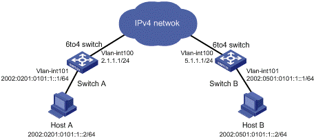
Figure 3-4 Network diagram for a 6to4 tunnel
III. Configuration procedure
l Configuration on Switch A
# Enable IPv6.
<SwitchA> system-view
[SwitchA] ipv6
# Configure a link aggregation group. Disable STP on the port before adding it into the link aggregation group.
[SwitchA] link-aggregation group 1 mode manual
[SwitchA] link-aggregation group 1 service-type tunnel
[SwitchA] interface GigabitEthernet 1/0/1
[SwitchA-GigabitEthernet1/0/1] stp disable
[SwitchA-GigabitEthernet1/0/1] port link-aggregation group 1
[SwitchA-GigabitEthernet1/0/1] quit
# Configure an IPv4 address for VLAN-interface 100.
[SwitchA] vlan 100
[SwitchA-vlan100] port GigabitEthernet 1/0/2
[SwitchA-vlan100] quit
[SwitchA] interface vlan-interface 100
[SwitchA-Vlan-interface100] ip address 2.1.1.1 24
[SwitchA-Vlan-interface100] quit
# Configure a route to VLAN-interface 100 of Switch B. (Here the next-hop address of the static route is represented by [nexthop]. In practice, you should configure the real next-hop address according to the network.)
[SwitchA] ip route-static 5.1.1.1 24 [nexthop]
# Configure an IPv6 address for VLAN-interface 101.
[SwitchA] vlan 101
[SwitchA-vlan101] port GigabitEthernet 1/0/3
[SwitchA-vlan101] quit
[SwitchA] interface vlan-interface 101
[SwitchA-Vlan-interface101] ipv6 address 2002:0201:0101:1::1/64
[SwitchA-Vlan-interface101] quit
# Configure a 6to4 tunnel.
[SwitchA] interface tunnel 0
[SwitchA-Tunnel0] ipv6 address 2002:201:101::1/64
[SwitchA-Tunnel0] source vlan-interface 100
[SwitchA-Tunnel0] tunnel-protocol ipv6-ipv4 6to4
[SwitchA-Tunnel0] quit
# Configure the tunnel to reference link aggregation group 1 in tunnel interface view.
[SwitchA-Tunnel0] aggregation-group 1
[SwitchA-Tunnel0] quit
# Configure a static route whose destination address is 2002::/16 and next-hop is the tunnel interface.
[SwitchA] ipv6 route-static 2002:: 16 tunnel 0
l Configuration on Switch B
# Enable IPv6.
<SwitchB> system-view
[SwitchB] ipv6
# Configure a link aggregation group. Disable STP on the port before adding it into the link aggregation group.
[SwitchB] link-aggregation group 1 mode manual
[SwitchB] link-aggregation group 1 service-type tunnel
[SwitchB] interface GigabitEthernet 1/0/1
[SwitchB-GigabitEthernet1/0/1] stp disable
[SwitchB-GigabitEthernet1/0/1] port link-aggregation group 1
[SwitchB-GigabitEthernet1/0/1] quit
# Configure an IPv4 address for VLAN-interface 100.
[SwitchB] vlan 100
[SwitchB-vlan100] port GigabitEthernet 1/0/2
[SwitchB-vlan100] quit
[SwitchB] interface vlan-interface 100
[SwitchB-Vlan-interface100] ip address 5.1.1.1 24
[SwitchB-Vlan-interface100] quit
# Configure a route to VLAN-interface 100 of Switch A. (Here the next-hop address of the static route is represented by [nexthop]. In practice, you should configure the real next-hop address according to the network.)
[SwitchB] ip route-static 2.1.1.1 24 [nexthop]
# Configure an IPv6 address for VLAN-interface 101.
[SwitchB] vlan 101
[SwitchB-vlan101] port GigabitEthernet 1/0/3
[SwitchB-vlan101] quit
[SwitchB] interface vlan-interface 101
[SwitchB-Vlan-interface101] ipv6 address 2002:0501:0101:1::1/64
[SwitchB-Vlan-interface101] quit
# Configure the 6to4 tunnel.
[SwitchB] interface tunnel 0
[SwitchB-Tunnel0] ipv6 address 2002:0501:0101::1/64
[SwitchB-Tunnel0] source vlan-interface 100
[SwitchB-Tunnel0] tunnel-protocol ipv6-ipv4 6to4
[SwitchB-Tunnel0] quit
# Configure the tunnel to reference link aggregation group 1 in tunnel interface view.
[SwitchB-Tunnel0] aggregation-group 1
[SwitchB-Tunnel0] quit
# Configure a static route whose destination address is 2002::/16 and the next hop is the tunnel interface.
[SwitchB] ipv6 route-static 2002:: 16 tunnel 0
IV. Configuration verification
After the above configuration, ping Host B from Host A or ping Host A from Host B.
D:\>ping6 -s 2002:201:101:1::2 2002:501:101:1::2
Pinging 2002:501:101:1::2
from 2002:201:101:1::2 with 32 bytes of data:
Reply from 2002:501:101:1::2: bytes=32 time=13ms
Reply from 2002:501:101:1::2: bytes=32 time=1ms
Reply from 2002:501:101:1::2: bytes=32 time=1ms
Reply from 2002:501:101:1::2: bytes=32 time<1ms
Ping statistics for 2002:501:101:1::2:
Packets: Sent = 4, Received = 4, Lost = 0 (0% loss),
Approximate round trip times in milli-seconds:
Minimum = 0ms, Maximum = 13ms, Average = 3ms
3.5 Configuring ISATAP Tunnel
3.5.1 Configuration Prerequisites
IP addresses are configured for interfaces such as VLAN interface, and loopback interface on the device. Such an interface can serve as the source interface of a tunnel to ensure that the tunnel destination address is reachable.
3.5.2 Configuration Procedure
Follow these steps to configure an ISATAP tunnel:
|
To do… |
Use the command… |
Remarks |
|
|
Enter system view |
system-view |
— |
|
|
Enable IPv6 |
ipv6 |
Required By default, the IPv6 forwarding function is disabled. |
|
|
Create a tunnel interface and enter tunnel interface view |
interface tunnel number |
Required By default, there is no tunnel interface on the device. |
|
|
Configure an IPv6 address for the tunnel interface |
Configure an IPv6 global unicast address or site-local address |
ipv6 address { ipv6-address prefix-length | ipv6-address/prefix-length } |
Required. Use either command. By default, no IPv6 global unicast address is configured for the tunnel interface. |
|
ipv6 address ipv6-address/prefix-length eui-64 |
|||
|
Configure an IPv6 link-local address |
ipv6 address auto link-local |
Optional By default, a link-local address will automatically be generated when an IPv6 global unicast address or link-local address is configured. |
|
|
ipv6 address ipv6-address link-local |
|||
|
Disable the RA message suppression |
undo ipv6 nd ra halt |
Required Enabled by default. |
|
|
Set an ISATAP tunnel |
tunnel-protocol ipv6-ipv4 isatap |
Required By default, the tunnel mode is manual. The same tunnel type should be configured at both ends of the tunnel. Otherwise, packet delivery will fail. |
|
|
Configure a source address or interface for the tunnel |
source { ip-address | interface-type interface-number } |
Required By default, no source address or interface is configured for the tunnel. |
|
|
Reference a link aggregation group |
aggregation-group aggregation-group-id |
Required By default, no link aggregation group ID is referenced. |
|
![]() Caution:
Caution:
l If the addresses of the tunnel interfaces at the two ends of a tunnel are not in the same network segment, a forwarding route through the tunnel to the peer must be configured so that the encapsulated packet can be forwarded normally. You can configure static or dynamic routes at both ends of the tunnel.
l The automatic tunnel interfaces encapsulated with the same protocol cannot share the same source IP address.
l Automatic tunnels do not support dynamic routing.
l When you configure a static route, you need to configure a route to the destination address (the destination IP address of the packet, instead of the IPv4 address of the tunnel destination) and set the next-hop to the tunnel interface number or network address at the local end of the tunnel. Such a route must be configured at both ends of the tunnel.
l Before referencing a link aggregation group on the tunnel interface to receive and send packets, make sure that the aggregation group has been configured. Otherwise, the tunnel interface will not be up to communicate.
3.5.3 Configuration Example
I. Network requirements
The destination address of a tunnel is an ISATAP address. It is required that IPv6 hosts in the IPv4 network can access the IPv6 network via an ISATAP tunnel.
II. Network diagram
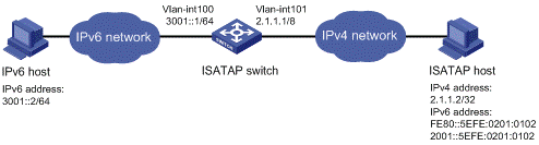
Figure 3-5 Network diagram for an ISATAP tunnel
III. Configuration procedure
l Configuration on the switch
# Enable IPv6.
<Switch> system-view
[Switch] ipv6
# Configure a link aggregation group. Disable STP on the port before adding it into the link aggregation group.
[Switch] link-aggregation group 1 mode manual
[Switch] link-aggregation group 1 service-type tunnel
[Switch] interface GigabitEthernet 1/0/1
[Switch-GigabitEthernet1/0/1] stp disable
[Switch-GigabitEthernet1/0/1] port link-aggregation group 1
[Switch-GigabitEthernet1/0/1] quit
# Configure addresses for interfaces.
[Switch] vlan 100
[Switch-vlan100] port GigabitEthernet 1/0/2
[Switch-vlan100] quit
[Switch] interface vlan-interface 100
[Switch-Vlan-interface100] ipv6 address 3001::1/64
[Switch-Vlan-interface100] quit
[Switch] vlan 101
[Switch-vlan101] port GigabitEthernet 1/0/3
[Switch-vlan101] quit
[Switch] interface vlan-interface 101
[Switch-Vlan-interface101] ip address 2.1.1.1 255.0.0.0
[Switch-Vlan-interface101] quit
# Configure an ISATAP tunnel.
[Switch] interface tunnel 0
[Switch-Tunnel0] ipv6 address 2001::1/64 eui-64
[Switch-Tunnel0] source vlan-interface 101
[Switch-Tunnel0] tunnel-protocol ipv6-ipv4 isatap
# Configure the tunnel to reference link aggregation group 1 in tunnel interface view.
[Switch-Tunnel0] aggregation-group 1
# Disable the RA suppression so that hosts can acquire information such as the address prefix from the RA message released by the ISATAP switch.
[Switch-Tunnel0] undo ipv6 nd ra halt
l Configuration on the ISATAP host
The specific configuration on the ISATAP host is related to its operating system. The following example shows the configuration of the host running the Windows XP.
# On a Windows XP-based host, the ISATAP interface is usually interface 2. Configure the IPv4 address of the ISATAP router on the interface to complete the configuration on the host. Before doing that, display the ISATAP interface information:
C:\>ipv6 if 2
Interface 2: Automatic Tunneling Pseudo-Interface
Guid {48FCE3FC-EC30-E50E-F1A7-71172AEEE3AE}
does not use Neighbor Discovery
does not use Router Discovery
routing preference 1
EUI-64 embedded IPv4 address: 0.0.0.0
router link-layer address: 0.0.0.0
preferred link-local fe80::5efe:2.1.1.2, life infinite
link MTU 1280 (true link MTU 65515)
current hop limit 128
reachable time 42500ms (base 30000ms)
retransmission interval 1000ms
DAD transmits 0
default site prefix length 48
# A link-local address (fe80::5efe:2.1.1.2) in the ISATAP format was automatically generated for the ISATAP interface. Configure the IPv4 address of the ISATAP switch on the ISATAP interface.
C:\>ipv6 rlu 2 2.1.1.1
# After carrying out the above command, look at the information on the ISATAP interface.
C:\>ipv6 if 2
Interface 2: Automatic Tunneling Pseudo-Interface
Guid {48FCE3FC-EC30-E50E-F1A7-71172AEEE3AE}
does not use Neighbor Discovery
uses Router Discovery
routing preference 1
EUI-64 embedded IPv4 address: 2.1.1.2
router link-layer address: 2.1.1.1
preferred global 2001::5efe:2.1.1.2, life 29d23h59m46s/6d23h59m46s (public)
preferred link-local fe80::5efe:2.1.1.2, life infinite
link MTU 1500 (true link MTU 65515)
current hop limit 255
reachable time 42500ms (base 30000ms)
retransmission interval 1000ms
DAD transmits 0
default site prefix length 48
# By comparison, it is found that the host acquires the address prefix 2001::/64 and automatically generates the address 2001::5efe:2.1.1.2. Meanwhile, “uses Switch Discovery” is displayed, indicating that the switch discovery function is enabled on the host. At this time, ping the IPv6 address of the tunnel interface of the switch. If the address is successfully pinged, an ISATAP tunnel is established.
IV. Configuration verification
After the above configurations, the ISATAP host can access the host in the IPV6 network.
3.6 Displaying and Maintaining Tunneling Configuration
|
To do… |
Use the command… |
Remarks |
|
Display information about a specified tunnel interface |
display interface tunnel [ number ] |
Available in any view |
|
Display IPv6 information related to a specified tunnel interface |
display ipv6 interface tunnel number |
Available in any view |
3.7 Troubleshooting Tunneling Configuration
Symptom: After the configuration of related parameters such as tunnel source address, tunnel destination address, and tunnel type, the tunnel interface is still not up.
Solution: Follow the steps below:
1) The common cause is that the physical interface of the tunnel source is not up. Use the display interface tunnel or display ipv6 interface tunnel commands to view whether the physical interface of the tunnel source is up. If the physical interface is down, use the debugging tunnel event command in user view to view the cause.
2) Another possible cause is that the tunnel destination is unreachable. Use the display ipv6 routing-table or display ip routing-table command to view whether the tunnel destination is reachable. If no routing entry is available for tunnel communication in the routing table, configure related routes.
