- Table of Contents
-
- H3C S5500-EI Series Switches Operation Manual-Release 2102(V1.01)
- 00-Preface
- 01-CLI configuration
- 02-RBAC configuration
- 03-Login management configuration
- 04-FTP and TFTP configuration
- 05-File system management configuration
- 06-Configuration file management configuration
- 07-Software upgrade configuration
- 08-Emergency shell configuration
- 09-Automatic configuration
- 10-Device management configuration
- 11-Tcl configuration
- 12-Python configuration
- 13-License management
- Related Documents
-
| Title | Size | Download |
|---|---|---|
| 13-IPv6 Routing Configuration | 648 KB |
Table of Contents
Chapter 1 IPv6 Static Routing Configuration
1.1 Introduction to IPv6 Static Routing
1.1.1 Features of IPv6 Static Routes
1.2 Configuring an IPv6 Static Route
1.2.1 Configuration prerequisites
1.2.2 Configuring an IPv6 Static Route
1.3 Displaying and Maintaining IPv6 Static Routes
1.4 IPv6 Static Routing Configuration Example
Chapter 2 IPv6 RIPng Configuration
2.1.3 RIPng Packet Processing Procedure
2.2 Configuring RIPng Basic Functions
2.2.1 Configuration Prerequisites
2.3 Configuring RIPng Route Control
2.3.1 Configuring an Additional Routing Metric
2.3.2 Configuring RIPng Route Summarization
2.3.3 Advertising a Default Route
2.3.4 Configuring a RIPng Route Filtering Policy
2.3.5 Configuring a Priority for RIPng
2.3.6 Configuring RIPng Route Redistribution
2.4 Tuning and Optimizing the RIPng Network
2.4.1 Configuring RIPng Timers
2.4.2 Configuring Split Horizon and Poison Reverse
2.4.3 Configuring Zero Field Check on RIPng Packets
2.4.4 Configuring the Maximum Number of Equal Cost Routes for Load Balancing
2.5 Displaying and Maintaining RIPng
2.6 RIPng Configuration Example
Chapter 3 IPv6 OSPFv3 Configuration
3.1.5 OSPFv3 Features Supported
3.2 IPv6 OSPFv3 Configuration Task List
3.3 Configuring OSPFv3 Basic Functions
3.3.2 Configuring OSPFv3 Basic Functions
3.4 Configuring OSPFv3 Area Parameters
3.4.2 Configuring an OSPFv3 Stub Area
3.4.3 Configuring OSPFv3 Virtual Links
3.5 Configuring OSPFv3 Routing Information Management
3.5.2 Configuring OSPFv3 Route Summarization
3.5.3 Configuring OSPFv3 Inbound Route Filtering
3.5.4 Configuring Link Costs for OSPFv3 Interfaces
3.5.5 Configuring the Maximum Number of OSPFv3 Load-balanced Routes
3.5.6 Configuring a Priority for OSPFv3
3.5.7 Configuring OSPFv3 Route Redistribution
3.6 Tuning and Optimizing an OSPFv3 Network
3.6.2 Configuring OSPFv3 Timers
3.6.3 Configuring the DR Priority for an Interface
3.6.4 Ignoring MTU Check for DD Packets
3.6.5 Disable Interfaces from Sending OSPFv3 Packets
3.6.6 Enable the Logging on Neighbor State Changes
3.7 Displaying and Maintaining OSPFv3
3.8 OSPFv3 Configuration Examples
3.8.1 Configuring OSPFv3 Areas
3.8.2 Configuring OSPFv3 DR Election
3.9 Troubleshooting OSPFv3 Configuration
3.9.1 No OSPFv3 Neighbor Relationship Established
3.9.2 Incorrect Routing Information
Chapter 4 IPv6 IS-IS Configuration
4.1 Introduction to IPv6 IS-IS
4.2 Configuring IPv6 IS-IS Basic Functions
4.2.1 Configuration Prerequisites
4.3 Configuring IPv6 IS-IS Routing Information Control
4.3.1 Configuration Prerequisites
4.4 Displaying and Maintaining IPv6 IS-IS
4.5 IPv6 IS-IS Configuration Example
Chapter 5 IPv6 BGP Configuration
5.3 Configuring IPv6 BGP Basic Functions
5.3.2 Configuring an IPv6 Peer
5.3.3 Advertising a Local IPv6 Route
5.3.4 Configuring a Preferred Value for Routes from a Peer/Peer Group
5.3.5 Specifying the Source Interface for Establishing TCP Connections
5.3.6 Allowing the establishment of a Non-Direct EBGP connection
5.3.7 Configuring a Description for a Peer/Peer Group
5.3.8 Disabling Session Establishment to a Peer/Peer Group
5.3.9 Logging Peer State Changes
5.4 Controlling Route Distribution and Reception
5.4.2 Configuring IPv6 BGP Route Redistribution
5.4.3 Advertising a Default Route to a Peer/Peer Group
5.4.4 Configuring Route Distribution Policy
5.4.5 Configuring Route Reception Policy
5.4.6 Configuring IPv6 BGP and IGP Route Synchronization
5.4.7 Configuring Route Dampening
5.5 Configuring IPv6 BGP Route Attributes
5.5.2 Configuring IPv6 BGP Preference and Default LOCAL_PREF and NEXT_HOP Attributes
5.5.3 Configuring the MED Attribute
5.5.4 Configuring the AS_PATH Attribute
5.6 Tuning and Optimizing IPv6 BGP Networks
5.6.2 Configuring IPv6 BGP Timers
5.6.3 Configuring IPv6 BGP Soft Reset
5.6.4 Configuring the Maximum Number of Load-Balanced Routes
5.7 Configuring a Large Scale IPv6 BGP Network
5.7.2 Configuring IPv6 BGP Peer Group
5.7.3 Configuring IPv6 BGP Community
5.7.4 Configuring an IPv6 BGP Route Reflector
5.8 Displaying and Maintaining IPv6 BGP Configuration
5.8.2 Resetting IPv6 BGP Connections
5.8.3 Clearing IPv6 BGP Information
5.9 IPv6 BGP Configuration Examples
5.9.1 IPv6 BGP Basic Configuration
5.9.2 IPv6 BGP Route Reflector Configuration
5.10 Troubleshooting IPv6 BGP Configuration
5.10.1 No IPv6 BGP Peer Relationship Established
Chapter 6 Routing Policy Configuration
6.1 Introduction to Routing Policy
6.1.3 Routing Policy Application
6.2.2 Defining an IPv6 Prefix List
6.2.3 Defining an AS Path List
6.2.4 Defining a Community List
6.2.5 Defining an Extended Community List
6.3 Configuring a Routing Policy
6.3.2 Creating a Routing Policy
6.3.3 Defining if-match Clauses for the Routing Policy
6.3.4 Defining apply Clauses for the Routing Policy
6.4 Displaying and Maintaining the Routing Policy
6.5 Routing Policy Configuration Example
6.5.1 Applying Routing Policy When Redistributing IPv6 Routes
6.6 Troubleshooting Routing Policy Configuration
6.6.1 IPv6 Routing Information Filtering Failure
Chapter 1 IPv6 Static Routing Configuration
& Note:
The term “router” in this document refers to a Layer 3 switch running routing protocols.
1.1 Introduction to IPv6 Static Routing
Static routes are special routes that are manually configured by network administrators. They work well in simple networks. Configuring and using them properly can improve the performance of networks and guarantee enough bandwidth for important applications.
However, static routes also have shortcomings: any topology changes could result in unavailable routes, requiring the network administrator to manually configure and modify the static routes.
1.1.1 Features of IPv6 Static Routes
Similar to IPv4 static routes, IPv6 static routes work well in simple IPv6 network environments.
Their major difference lies in the destination and next hop addresses. IPv6 static routes use IPv6 addresses whereas IPv4 static routes use IPv4 addresses.
1.1.2 Default IPv6 Route
The IPv6 static route that has the destination address configured as ::/0 (indicating a prefix length of 0) is the default IPv6 route. If the destination address of an IPv6 packet does not match any entry in the routing table, this default route will be used to forward the packet.
1.2 Configuring an IPv6 Static Route
In small IPv6 networks, IPv6 static routes can be used to forward packets. In comparison to dynamic routes, it helps to save network bandwidth.
1.2.1 Configuration prerequisites
l Enabling IPv6 packet forwarding
l Ensuring that the neighboring nodes are IPv6 reachable
1.2.2 Configuring an IPv6 Static Route
Follow these steps to configure an IPv6 static route:
|
To do... |
Use the commands… |
Remarks |
|
Enter system view |
System-view |
— |
|
Configure an IPv6 static route |
ipv6 route-static ipv6-address prefix-length [ interface-type interface-number ] nexthop-address [ preference preference-value ] |
Required The default preference of IPv6 static routes is 60. |
1.3 Displaying and Maintaining IPv6 Static Routes
|
To do... |
Use the command... |
Remarks |
|
Display IPv6 static route information |
display ipv6 routing-table protocol static [ inactive | verbose ] |
Available in any view |
|
Remove all IPv6 static routes |
delete ipv6 static-routes all |
Available in system view |
& Note:
Using the undo ipv6 route-static command can delete a single IPv6 static route, while using the delete ipv6 static-routes all command deletes all IPv6 static routes including the default route.
1.4 IPv6 Static Routing Configuration Example
I. Network requirements
With IPv6 static routes configured, all hosts and switches can interact with each other.
II. Network diagram
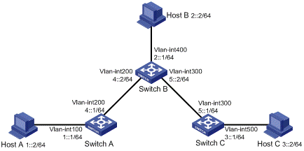
Figure 1-1 Network diagram for static routes
III. Configuration procedure
1) Configure the IPv6 addresses of all VLAN interfaces (Omitted)
2) Configure IPv6 static routes.
# Configure the default IPv6 static route on Switch A.
<SwitchA> system-view
[SwitchA] ipv6
[SwitchA] ipv6 route-static :: 0 4::2
# Configure two IPv6 static routes on Switch B.
<SwitchB> system-view
[SwitchB] ipv6
[SwitchB] ipv6 route-static 1:: 64 4::1
[SwitchB] ipv6 route-static 3:: 64 5::1
# Configure the default IPv6 static route on Switch C.
<SwitchC> system-view
[SwitchC] ipv6
[SwitchC] ipv6 route-static :: 0 5::2
3) Configure the IPv6 addresses of hosts and gateways.
Configure the IPv6 addresses of all the hosts based upon the network diagram, configure the default gateway of Host A as 1::1, that of Host B as 2::1, and that of Host C as 3::1.
4) Display configuration information
# Display the IPv6 routing table of Switch A.
[SwitchA] display ipv6 routing-table
Routing Table :
Destinations : 7 Routes : 7
Destination: ::/0 Protocol : Static
NextHop : 4::2 Preference: 60
Interface : Vlan200 Cost : 0
Destination: ::1/128 Protocol : Direct
NextHop : ::1 Preference: 0
Interface : InLoop0 Cost : 0
Destination: 1::/64 Protocol : Direct
NextHop : 1::1 Preference: 0
Interface : Vlan100 Cost : 0
Destination: 1::1/128 Protocol : Direct
NextHop : ::1 Preference: 0
Interface : InLoop0 Cost : 0
Destination: 4::/64 Protocol : Direct
NextHop : 4::1 Preference: 0
Interface : Vlan200 Cost : 0
Destination: 4::1/128 Protocol : Direct
NextHop : ::1 Preference: 0
Interface : InLoop0 Cost : 0
Destination: FE80::/10 Protocol : Direct
NextHop : :: Preference: 0
Interface : NULL0 Cost : 0
# Verify the connectivity with the ping command.
[SwitchA] ping ipv6 3::1
PING 3::1 : 56 data bytes, press CTRL_C to break
Reply from 3::1
bytes=56 Sequence=1 hop limit=254 time = 63 ms
Reply from 3::1
bytes=56 Sequence=2 hop limit=254 time = 62 ms
Reply from 3::1
bytes=56 Sequence=3 hop limit=254 time = 62 ms
Reply from 3::1
bytes=56 Sequence=4 hop limit=254 time = 63 ms
Reply from 3::1
bytes=56 Sequence=5 hop limit=254 time = 63 ms
--- 3::1 ping statistics ---
5 packet(s) transmitted
5 packet(s) received
0.00% packet loss
round-trip min/avg/max = 62/62/63 ms
Chapter 2 IPv6 RIPng Configuration
& Note:
l The term “router” in this document refers to a Layer 3 switch running routing protocols.
l The S5500-EI series only support single RIPng process.
2.1 Introduction to RIPng
RIP next generation (RIPng) is an extension of RIP-2 for IPv4. Most RIP concepts are applicable in RIPng.
RIPng for IPv6 made the following changes to RIP:
l UDP port number: RIPng uses UDP port 521 for sending and receiving routing information.
l Multicast address: RIPng uses FF02:9 as the link-local multicast address.
l Destination Prefix: 128-bit destination address prefix.
l Next hop: 128-bit IPv6 address.
l Source address: RIPng uses FE80::/10 as the link-local source address
2.1.1 RIPng Working Mechanism
RIPng is a routing protocol based on the distance vector (D-V) algorithm. RIPng uses UDP packets to exchange routing information through port 521.
RIPng uses a hop count to measure the distance to a destination. The hop count is referred to as metric or cost. The hop count from a router to a directly connected network is 0. The hop count between two directly connected routers is 1. When the hop count is greater than or equal to 16, the destination network or host is unreachable.
By default, the routing update is sent every 30 seconds. If the router receives no routing updates from a neighbor after 180 seconds, the routes learned from the neighbor are considered as unreachable. After another 240 seconds, if no routing update is received, the router will remove these routes from the routing table.
RIPng supports Split Horizon and Poison Reverse to prevent routing loops, and route redistribution.
Each RIPng router maintains a routing database, including route entries of all reachable destinations. A route entry contains the following information:
l Destination address: IPv6 address of a host or a network.
l Next hop address: IPv6 address of a neighbor along the path to the destination.
l Egress interface: Outbound interface that forwards IPv6 packets.
l Metric: Cost from the local router to the destination.
l Route time: Time that elapsed since a route entry is last changed. Each time a route entry is modified, the routing time is set to 0.
l Route tag: Identifies the route, used in routing policy to control routing information.
2.1.2 RIPng Packet Format
I. Basic format
A RIPng packet consists of a header and multiple route table entries (RTEs). The maximum number of RTEs in a packet depends on the MTU of the sending interface.
Figure 2-1 shows the packet format of RIPng.
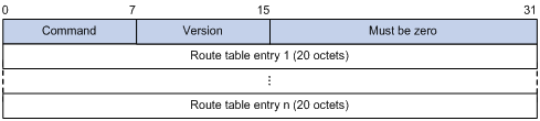
Figure 2-1 RIPng basic packet format
l Command: Type of message. 0x01 indicates Request, 0x02 indicates Response.
l Version: Version of RIPng. It can only be 0x01 currently.
l RTE: Route table entry, 20 bytes for each entry.
II. RTE format
There are two types of RTE in RIPng.
l Next hop RTE: Defines the IPv6 address of a next hop
l IPv6 prefix RTE: Describes the destination IPv6 address, route tag, prefix length and metric in the RIPng routing table.
Figure 2-2 shows the format of the next hop RTE:
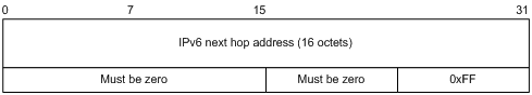
Figure 2-2 Next hop RTE format
IPv6 next hop address is the IPv6 address of the next hop.
Figure 2-3 shows the format of the IPv6 prefix RTE.
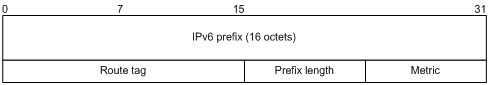
Figure 2-3 IPv6 prefix RTE format
l IPv6 prefix: Destination IPv6 address prefix.
l Route tag: Route tag.
l Prefix len: Length of the IPv6 address prefix.
l Metric: Cost of a route.
2.1.3 RIPng Packet Processing Procedure
I. Request packet
When a RIPng router first starts or needs to update some entries in its routing table, generally a multicast request packet is sent to ask for needed routes from neighbors.
The receiving RIPng router processes RTEs in the request. If there is only one RTE with the IPv6 prefix and prefix length both being 0, and with a metric value of 16, the RIPng router will respond with the entire routing table information in response messages. If there are multiple RTEs in the request message, the RIPng router will examine each RTE, update its metric, and send the requested routing information to the requesting router in the response packet.
II. Response packet
The response packet containing the local routing table information is generated as:
l A response to a request
l An update periodically
l A trigged update caused by route change
After receiving a response, a router checks the validity of the response before adding the route to its routing table, such as whether the source IPv6 address is the link-local address, whether the port number is correct. The response packet failed the check will be discarded.
2.1.4 Protocols and Standards
l RFC2080: RIPng for IPv6
l RFC2081: RIPng Protocol Applicability Statement
l RFC2453: RIP Version 2
2.2 Configuring RIPng Basic Functions
In this section, you are presented with the information to configure the basic RIPng features.
You need to enable RIPng first before configuring other tasks, but it is not necessary for RIPng related interface configurations, such as assigning an IPv6 address.
2.2.1 Configuration Prerequisites
Before the configuration, accomplish the following tasks first:
l Enable IPv6 packet forwarding.
l Configure an IP address for each interface, and make sure all nodes are reachable.
2.2.2 Configuration Procedure
Follow these steps to configure the basic RIPng functions:
|
Use the command... |
Remarks |
|
|
Enter system view |
system-view |
–– |
|
Create a RIPng process and enter RIPng view |
ripng [ process-id ] |
Required Not created by default |
|
Return to system view |
quit |
— |
|
Enter interface view |
interface interface-type interface-number |
–– |
|
Enable RIPng on the interface |
ripng process-id enable |
Required Disabled by default |
& Note:
If RIPng is not enabled on an interface, the interface will not send and receive any RIPng route.
2.3 Configuring RIPng Route Control
Before the configuration, accomplish the following tasks first:
l Configure an IPv6 address on each interface, and make sure all nodes are reachable.
l Configure RIPng basic functions
l Define an IPv6 ACL before using it for route filtering. Refer to ACL configuration for related information.
l Define an IPv6 address prefix list before using it for route filtering. Refer to section 6.2.2 "Defining an IPv6 Prefix List" for related information.
2.3.1 Configuring an Additional Routing Metric
An additional routing metric can be added to the metric of an inbound or outbound RIP route, namely, the inbound and outbound additional metric.
The outbound additional metric is added to the metric of a sent route, the route’s metric in the routing table is not changed.
The inbound additional metric is added to the metric of a received route before the route is added into the routing table, so the route’s metric is changed.
Follow these steps to configure an inbound/outbound additional routing metric:
|
Use the command... |
Remarks |
|
|
Enter system view |
system-view |
–– |
|
Enter interface view |
interface interface-type interface-number |
–– |
|
Specify an inbound routing additional metric |
ripng metricin value |
Optional 0 by default |
|
Specify an outbound routing additional metric |
ripng metricout value |
Optional 1 by default |
2.3.2 Configuring RIPng Route Summarization
Follow these steps to configure RIPng route summarization:
|
To do... |
Use the command... |
Remarks |
|
Enter system view |
system-view |
–– |
|
Enter interface view |
interface interface-type interface-number |
–– |
|
Advertise a summary IPv6 prefix |
ripng summary-address ipv6-address prefix-length |
Required |
2.3.3 Advertising a Default Route
Follow these steps to advertise a default route:
|
To do... |
Use the command... |
Remarks |
|
Enter system view |
system-view |
–– |
|
Enter interface view |
interface interface-type interface-number |
–– |
|
Advertise a default route |
ripng default-route { only | originate } [ cost cost ] |
Required Not advertised by default |
& Note:
With this feature enabled, a default route is advertised via the specified interface regardless of whether the default route is available in the local IPv6 routing table.
2.3.4 Configuring a RIPng Route Filtering Policy
You can reference a configured IPv6 ACL or prefix list to filter received/advertised routing information as needed. For filtering outbound routes, you can also specify a routing protocol from which to filter routing information redistributed.
Follow these steps to configure a RIPng route filtering policy:
|
To do... |
Use the command... |
Remarks |
|
Enter system view |
system-view |
–– |
|
Enter RIPng view |
ripng [ process-id ] |
–– |
|
Configure a filter policy to filter incoming routes |
filter-policy { acl6-number | ipv6-prefix ipv6-prefix-name } import |
Required By default, RIPng does not filter incoming routing information. |
|
Configure a filter policy to filter outgoing routes |
filter-policy { acl6-number | ipv6-prefix ipv6-prefix-name } export [ protocol [ process-id ] ] |
Required By default, RIPng does not filter outgoing routing information. |
2.3.5 Configuring a Priority for RIPng
Any routing protocol has its own protocol priority used for optimal route selection. You can set a priority for RIPng manually. The smaller the value is, the higher the priority is.
Follow these steps to configure a RIPng priority:
|
To do... |
Use the command... |
Remarks |
|
Enter system view |
system-view |
— |
|
Enter RIPng view |
ripng [ process-id ] |
— |
|
Configure a RIPng priority |
preference [ route-policy route-policy-name ] preference |
Optional By default, the RIPng priority is 100. |
2.3.6 Configuring RIPng Route Redistribution
Follow these steps to configure RIPng route redistribution:
|
To do... |
Use the command... |
Remarks |
|
Enter system view |
system-view |
–– |
|
Enter RIPng view |
ripng [ process-id ] |
–– |
|
Configure a default routing metric for redistributed routes |
default cost cost |
Optional By default, the default metric of redistributed routes is 0. |
|
Redistribute routes from another routing protocol |
import-route protocol [ process-id ] [ allow-ibgp ] [ cost cost | route-policy route-policy-name ] * |
Required No route redistribution is configured by default. |
2.4 Tuning and Optimizing the RIPng Network
This section describes how to tune and optimize the performance of the RIPng network as well as applications under special network environments. Before tuning and optimizing the RIPng network, complete the following tasks:
l Configure a network layer address for each interface
l Configure the basic RIPng functions
This section covers the following topics:
l Configuring Split Horizon and Poison Reverse
l Configuring Zero Field Check on RIPng Packets
l Configuring the Maximum Number of Equal Cost Routes for Load Balancing
2.4.1 Configuring RIPng Timers
You can adjust RIPng timers to optimize the performance of the RIPng network.
Follow these steps to configure RIPng timers:
|
To do... |
Use the command... |
Remarks |
|
Enter system view |
system-view |
— |
|
Enter RIPng view |
ripng [ process-id ] |
— |
|
Configure RIPng timers |
timers { garbage-collect garbage-collect-value | suppress suppress-value | timeout timeout-value | update update-value } * |
Optional. The RIPng timers have the following defaults: l 30 seconds for the update timer l 180 seconds for the timeout timer l 120 seconds for the suppress timer l 120 seconds for the garbage-collect timer |
& Note:
When adjusting RIPng timers, you should consider the network performance and perform unified configurations on routers running RIPng to avoid unnecessary network traffic increase or route oscillation.
2.4.2 Configuring Split Horizon and Poison Reverse
& Note:
If both the split horizon and poison reverse are configured, only the poison reverse function takes effect.
I. Configure the split horizon
The split horizon function disables a route learned from an interface from being advertised via the interface to prevent routing loops between neighbors.
Follow these steps to configure the split horizon:
|
To do... |
Use the command... |
Remarks |
|
Enter system view |
system-view |
–– |
|
Enter interface view |
interface interface-type interface-number |
–– |
|
Enable the split horizon function |
ripng split-horizon |
Optional Enabled by default |
& Note:
Generally, you are recommended to enable the split horizon to prevent routing loops.
II. Configuring the poison reverse function
The poison reverse function enables a route learned from an interface to be advertised via the interface. However, the metric of the route is set to 16. That is to say, the route is unreachable.
Follow these steps to configure poison reverse:
|
To do... |
Use the command... |
Remarks |
|
Enter system view |
system-view |
–– |
|
Enter interface view |
interface interface-type interface-number |
–– |
|
Enable the poison reverse function |
ripng poison-reverse |
Required Disabled by default |
2.4.3 Configuring Zero Field Check on RIPng Packets
Some fields in the RIPng packet must be zero. These fields are called zero fields. With zero field check on RIPng packets enabled, if such a field contains a non-zero value, the entire RIPng packet will be discarded. If you are sure that all packets are trusty, you can disable the zero field check to save the CPU processing time.
Follow these steps to configure RIPng zero field check:
|
To do... |
Use the command... |
Remarks |
|
Enter system view |
system-view |
–– |
|
Enter RIPng view |
ripng [ process-id ] |
–– |
|
Enable the zero field check |
checkzero |
Optional Enabled by default |
2.4.4 Configuring the Maximum Number of Equal Cost Routes for Load Balancing
Follow these steps to configure the maximum number of equal cost RIPng routes for load balancing:
|
To do... |
Use the command... |
Remarks |
|
Enter system view |
system-view |
–– |
|
Enter RIPng view |
ripng [ process-id ] |
–– |
|
Configure the maximum number of equal cost RIPng routes for load balancing |
maximum load-balancing number |
Optional 4 by default |
2.5 Displaying and Maintaining RIPng
|
To do... |
Use the command... |
Remarks |
|
Display configuration information of a RIPng process |
display ripng [ process-id ] |
Available in any view |
|
Display routes in the RIPng database |
display ripng process-id database |
Available in any view |
|
Display the routing information of a specified RIPng process |
display ripng process-id route |
Available in any view |
|
Display RIPng interface information |
display ripng process-id interface [ interface-type interface-number ] |
Available in any view |
2.6 RIPng Configuration Example
I. Network requirements
As shown in Figure 2-4, all switches run RIPng. Configure Switch B to filter the route (3::/64) learnt from Switch C, which means the route will not be added to the routing table of Switch B, and Switch B will not forward it to Switch A.
II. Network diagram
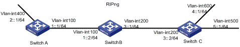
Figure 2-4 Network diagram for RIPng configuration
III. Configuration procedure
1) Configure the IPv6 address for each interface (omitted)
2) Configure basic RIPng functions
# Configure Switch A.
<SwitchA> system-view
[SwitchA] ipv6
[SwitchA] ripng 1
[SwitchA-ripng-1] quit
[SwitchA] interface vlan-interface 100
[SwitchA-Vlan-interface100] ripng 1 enable
[SwitchA-Vlan-interface100] quit
[SwitchA] interface vlan-interface 400
[SwitchA-Vlan-interface400] ripng 1 enable
[SwitchA-Vlan-interface400] quit
# Configure Switch B.
<SwitchB> system-view
[SwitchB] ipv6
[SwitchB] ripng 1
[SwitchB-ripng-1] quit
[SwitchB] interface vlan-interface 200
[SwitchB-Vlan-interface200] ripng 1 enable
[SwitchB-Vlan-interface200] quit
[SwitchB] interface vlan-interface 100
[SwitchB-Vlan-interface100] ripng 1 enable
[SwitchB-Vlan-interface100] quit
# Configure Switch C.
<SwitchC> system-view
[SwitchC] ipv6
[SwitchC] ripng 1
[SwitchC-ripng-1] quit
[SwitchC] interface vlan-interface 200
[SwitchC-Vlan-interface200] ripng 1 enable
[SwitchC-Vlan-interface200] quit
[SwitchC] interface Vlan-interface 500
[SwitchC-Vlan-interface500] ripng 1 enable
[SwitchC-Vlan-interface500] quit
[SwitchC] interface vlan-interface 600
[SwitchC-Vlan-interface600] ripng 1 enable
[SwitchC-Vlan-interface600] quit
# Display the routing table of Switch B.
[SwitchB] display ripng 1 route
Route Flags: A - Aging, S - Suppressed, G - Garbage-collect
----------------------------------------------------------------
Peer FE80::20F:E2FF:FE23:82F5 on Vlan-interface100
Dest 1::/64,
via FE80::20F:E2FF:FE23:82F5, cost 1, tag 0, A, 6 Sec
Dest 2::/64,
via FE80::20F:E2FF:FE23:82F5, cost 1, tag 0, A, 6 Sec
Peer FE80::20F:E2FF:FE00:100 on Vlan-interface200
Dest 3::/64,
via FE80::20F:E2FF:FE00:100, cost 1, tag 0, A, 11 Sec
Dest 4::/64,
via FE80::20F:E2FF:FE00:100, cost 1, tag 0, A, 11 Sec
Dest 5::/64,
via FE80::20F:E2FF:FE00:100, cost 1, tag 0, A, 11 Sec
# Display the routing table of Switch A.
[SwitchA] display ripng 1 route
Route Flags: A - Aging, S - Suppressed, G - Garbage-collect
----------------------------------------------------------------
Peer FE80::200:2FF:FE64:8904 on Vlan-interface100
Dest 1::/64,
via FE80::200:2FF:FE64:8904, cost 1, tag 0, A, 31 Sec
Dest 4::/64,
via FE80::200:2FF:FE64:8904, cost 2, tag 0, A, 31 Sec
Dest 5::/64,
via FE80::200:2FF:FE64:8904, cost 2, tag 0, A, 31 Sec
Dest 3::/64,
via FE80::200:2FF:FE64:8904, cost 1, tag 0, A, 31 Sec
3) Configure Switch B to filter incoming and outgoing routes.
[SwitchB] acl ipv6 number 2000
[SwitchB-acl6-basic-2000] rule deny source 3::/64
[SwitchB-acl6-basic-2000] rule permit
[SwitchB-acl6-basic-2000] quit
[SwitchB] ripng 1
[SwitchB-ripng-1] filter-policy 2000 import
[SwitchB-ripng-1] filter-policy 2000 export
[SwitchB-ripng-1] quit
# Display routing tables of Switch B and Switch A.
[SwitchB] display ripng 1 route
Route Flags: A - Aging, S - Suppressed, G - Garbage-collect
----------------------------------------------------------------
Peer FE80::20F:E2FF:FE23:82F5 on Vlan-interface100
Dest 1::/64,
via FE80::20F:E2FF:FE23:82F5, cost 1, tag 0, A, 2 Sec
Dest 2::/64,
via FE80::20F:E2FF:FE23:82F5, cost 1, tag 0, A, 2 Sec
Peer FE80::20F:E2FF:FE00:100 on Vlan-interface200
Dest 4::/64,
via FE80::20F:E2FF:FE00:100, cost 1, tag 0, A, 5 Sec
Dest 5::/64,
via FE80::20F:E2FF:FE00:100, cost 1, tag 0, A, 5 Sec
[SwitchA] display ripng 1 route
Route Flags: A - Aging, S - Suppressed, G - Garbage-collect
----------------------------------------------------------------
Peer FE80::20F:E2FF:FE00:1235 on Vlan-interface100
Dest 1::/64,
via FE80::20F:E2FF:FE00:1235, cost 1, tag 0, A, 2 Sec
Dest 4::/64,
via FE80::20F:E2FF:FE00:1235, cost 2, tag 0, A, 2 Sec
Dest 5::/64,
via FE80::20F:E2FF:FE00:1235, cost 2, tag 0, A, 2 Sec
Chapter 3 IPv6 OSPFv3 Configuration
l The term “router” in this document refers to a Layer 3 switch running routing protocols.
l The S5500-EI series only support single OSPFv3 process.
3.1 Introduction to OSPFv3
3.1.1 OSPFv3 Overview
OSPFv3 is OSPF (Open Shortest Path First) version 3 for short, supporting IPv6 and compliant with RFC2740 (OSPF for IPv6).
Identical parts between OSPFv3 and OSPFv2:
l 32 bits router ID and area ID
l Packets: Hello, DD (Data Description), LSR (Link State Request), LSU (Link State Update), LSAck (Link State Acknowledgment)
l Mechanisms for finding neighbors and establishing adjacencies
l Mechanisms for LSA flooding and aging
Differences between OSPFv3 and OSPFv2:
l OSPFv3 now runs on a per-link basis, instead of on a per-IP-subnet basis.
l OSPFv3 supports multiple instances per link.
l OSPFv3 identifies neighbors by Router ID, while OSPFv2 by IP address.
3.1.2 OSPFv3 Packets
OSPFv3 has also five types of packets: hello, DD, LSR, LSU, and LSAck.
The five packets have the same packet header, which different from the OSPFv2 packet header is only 16 bytes in length, has no authentication field, but is added with an Instance ID field to support multi-instance per link.
Figure 3-1 gives the OSPFv3 packet header.
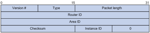
Figure 3-1 OSPFv3 packet header
l Version #: Version of OSPF, which is 3 for OSPFv3.
l Type: Type of OSPF packet, from 1 to 5 are hello, DD, LSR, LSU, and LSAck respectively.
l Packet Length: Packet length in bytes, including header.
l Instance ID: Instance ID for a link.
l 0: Reserved, which must be 0.
3.1.3 OSPFv3 LSA Types
OSPFv3 sends routing information in LSAs, which as defined in RFC2740 have the following types:
l Router-LSAs: Originated by all routers. This LSA describes the collected states of the router's interfaces to an area. Flooded throughout a single area only.
l Network-LSAs: Originated for broadcast and NBMA networks by the Designated Router. This LSA contains the list of routers connected to the network. Flooded throughout a single area only.
l Inter-Area-Prefix-LSAs: Similar to Type 3 LSA of OSPFv2, originated by ABRs (Area Border Routers), and flooded throughout the LSA's associated area. Each Inter-Area-Prefix-LSA describes a route with IPv6 address prefix to a destination outside the area, yet still inside the AS (an inter-area route).
l Inter-Area-Router-LSAs: Similar to Type 4 LSA of OSPFv2, originated by ABRs and flooded throughout the LSA's associated area. Each Inter-Area-Router-LSA describes a route to ASBR (Autonomous System Boundary Router).
l AS-external-LSAs: Originated by ASBRs, and flooded throughout the AS (except Stub and NSSA areas). Each AS-external-LSA describes a route to another Autonomous System. A default route can be described by an AS external LSA.
l Link-LSAs: A router originates a separate Link-LSA for each attached link. Link-LSAs have link-local flooding scope. Each Link-LSA describes the IPv6 address prefix of the link and Link-local address of the router.
l Intra-Area-Prefix-LSAs: Each Intra-Area-Prefix-LSA contains IPv6 prefix information on a router, stub area or transit area information, and has area flooding scope. It was introduced because Router-LSAs and Network-LSAs contain no address information now.
3.1.4 Timers of OSPFv3
Timers in OSPFv3 include:
l OSPFv3 packet timer
l LSA delay timer
l SPF timer
I. OSPFv3 packet timer
Hello packets are sent periodically between neighboring routers for finding and maintaining neighbor relationships, or for DR/BDR election. The hello interval must be identical on neighboring interfaces. The smaller the hello interval, the faster the network convergence speed and the bigger the network load.
If a router receives no hello packet from a neighbor after a period, it will declare the peer is down. The period is called dead interval.
After sending an LSA to its adjacency, a router waits for an acknowledgment from the adjacency. If no response is received after retransmission interval elapses, the router will send again the LSA. The retransmission interval must be longer than the round-trip time of the LSA in between.
II. LSA delay time
Each LSA has an age in the local LSDB (incremented by 1 per second), but an LSA is not aged on transmission. You need to add an LSA delay time into the age time before transmission, which is important for low speed networks.
III. SPF timer
Whenever LSDB changes, SPF recalculation happens. If recalculations become so frequent, a large amount of resources will be occupied, reducing operation efficiency of routers. You can adjust SPF calculation interval and delay time to protect networks from being overloaded due to frequent changes.
3.1.5 OSPFv3 Features Supported
l Basic features defined in RFC2740
l OSPFv3 stub area
3.1.6 Related RFCs
l RFC2740: OSPF for IPv6
l RFC2328: OSPF Version 2
3.2 IPv6 OSPFv3 Configuration Task List
Complete the following tasks to configure OSPFv3:
|
Task |
Remarks |
|
|
Required |
||
|
Optional |
||
|
Optional |
||
|
Optional |
||
|
Optional |
||
|
Optional |
||
|
Configuring the Maximum Number of OSPFv3 Load-balanced Routes |
Optional |
|
|
Optional |
||
|
Optional |
||
|
Optional |
||
|
Optional |
||
|
Optional |
||
|
Optional |
||
|
Optional |
||
3.3 Configuring OSPFv3 Basic Functions
3.3.1 Prerequisites
l Make neighboring nodes accessible with each other at network layer.
l Enable IPv6 packet forwarding
3.3.2 Configuring OSPFv3 Basic Functions
Follow these steps to configure OSPFv3 basic functions:
|
To do... |
Use the command... |
Remarks |
|
Enter system view |
system-view |
— |
|
Enable OSPFv3 and enter its view |
ospfv3 [ process-id ] |
Required |
|
Specify a router ID |
router-id router-id |
Required |
|
Enter interface view |
interface interface-type interface-number |
— |
|
Enable OSPFv3 on the interface |
ospfv3 process-id area area-id [ instance instance-id ] |
Required Not enabled by default |
& Note:
l Configure an OSPFv3 process ID when enabling OSPFv3. The process ID takes effect locally, without affecting packet exchange between routers.
l When configuring a router ID, make sure each router has a unique ID.
l You need to specify a router ID manually, which is necessary to make OSPFv3 work.
3.4 Configuring OSPFv3 Area Parameters
The stub area and virtual link support of OSPFv3 has the same principle and application environments with OSPFv2.
Splitting an OSPFv3 AS into multiple areas reduces the number of LSAs on networks and extends OSPFv3 application. For those non-backbone areas residing on the AS boundary, you can configure them as Stub areas to further reduce the size of routing tables on routers in these areas and the number of LSAs.
Non-backbone areas exchange routing information via the backbone area. Therefore, the backbone and non-backbone areas, including the backbone itself must maintain connectivity. In practice, necessary physical links may not be available for connectivity. You can configure virtual links to address it.
3.4.1 Prerequisites
l Enable IPv6 packet forwarding
l Configure OSPFv3 basic functions
3.4.2 Configuring an OSPFv3 Stub Area
Follow these steps to configure an OSPFv3 stub area:
|
To do... |
Use the command... |
Remarks |
|
Enter system view |
system-view |
— |
|
Enter OSPFv3 view |
ospfv3 [ process-id ] |
— |
|
Enter OSPFv3 area view |
area area-id |
— |
|
Configure the area as a stub area |
stub [ no-summary ] |
Required Not configured by default |
|
Configure the default route cost of sending a packet to the stub area |
default-cost value |
Optional Defaults to 1 |
& Note:
l Configurations on the OSPFv3 routers attached to the same area must be consistent. Otherwise, neighbor relationships cannot be established between adjacent routers.
l You cannot delete an OSPFv3 area directly. Only when you remove all configurations in area view and all interfaces attached to the area become down, can the area be removed automatically.
l All routers attached to a stub area must be configured with the stub command. The keyword no-summary is only available on the ABR.
l If you use the stub command with the keyword no-summary on an ABR, the ABR distributes a default summary LSA into the area rather than generating an AS-external-LSA or Inter-Area-Prefix-LSA. The stub area of this kind is also known as totally stub area.
3.4.3 Configuring OSPFv3 Virtual Links
You can configure virtual links to maintain connectivity between non-backbone areas and the backbone, or in the backbone itself.
Follow these steps to configure a virtual link:
|
To do... |
Use the command... |
Remarks |
|
Enter system view |
system-view |
— |
|
Enter OSPFv3 view |
ospfv3 [ process-id ] |
— |
|
Enter OSPFv3 area view |
area area-id |
— |
|
Create and configure a virtual link |
vlink-peer router-id [ hello seconds | retransmit seconds | trans-delay seconds | dead seconds | instance instance-id ] * |
Required |
& Note:
Both ends of a virtual link are ABRs that are configured with the vlink-peer command.
3.5 Configuring OSPFv3 Routing Information Management
This section is to configure management of OSPF routing information advertisement and reception, and route redistribution from other protocols.
3.5.1 Prerequisites
l Enable IPv6 packet forwarding
l Configure OSPFv3 basic functions
3.5.2 Configuring OSPFv3 Route Summarization
Follow these steps to configure route summarization between areas:
|
To do... |
Use the command... |
Remarks |
|
Enter system view |
system-view |
— |
|
Enter OSPFv3 view |
ospfv3 [ process-id ] |
— |
|
Enter OSPFv3 area view |
area area-id |
— |
|
Configure a summary route |
abr-summary ipv6-address prefix-length [ not-advertise ] |
Required Not configured by default |
& Note:
The abr-summary command is available on ABRs only. If contiguous network segments are available in an area, you can use the command to summarize them into one network segment on the ABR. The ABR will advertise only the summary route. Any LSA falling into the specified network segment will not be advertised, reducing the LSDB size in other areas.
3.5.3 Configuring OSPFv3 Inbound Route Filtering
You can configure OSPFv3 to filter routes that are computed from received LSAs according to some rules.
Follow these steps to configure inbound route filtering:
|
To do... |
Use the command... |
Remarks |
|
Enter system view |
system-view |
— |
|
Enter OSPFv3 view |
ospfv3 [ process-id ] |
— |
|
Configure inbound route filtering |
filter-policy { acl-number | ipv6-prefix ipv6-prefix-name } import |
Required Not configured by default |
& Note:
Use of the filter-policy import command can only filter routes computed by OSPFv3. Only routes not filtered can be added into the local routing table.
3.5.4 Configuring Link Costs for OSPFv3 Interfaces
You can configure OSPFv3 link costs for interfaces to adjust routing calculation.
Follow these steps to configure the link cost for an OSPFv3 interface:
|
To do... |
Use the command... |
Remarks |
|
Enter system view |
system-view |
— |
|
Enter interface view |
interface interface-type interface-number |
— |
|
Configure the cost for the interface |
ospfv3 cost value [ instance instance-id ] |
Optional 1 by default |
3.5.5 Configuring the Maximum Number of OSPFv3 Load-balanced Routes
If multiple routes to a destination are available, using load balancing to send IPv6 packets on these routes in turn can improve link utility.
Follow these steps to configure the maximum number of load-balanced routes:
|
To do... |
Use the command... |
Remarks |
|
Enter system view |
system-view |
— |
|
Enter OSPFv3 view |
ospfv3 [ process-id ] |
— |
|
Specify the maximum number of load-balanced routes |
maximum load-balancing maximum |
Optional 4 by default |
3.5.6 Configuring a Priority for OSPFv3
A router may run multiple routing protocols. The system assigns a priority for each protocol. When these routing protocols find the same route, the route found by the protocol with the highest priority is selected.
Follow these steps to configure a priority for OSPFv3:
|
To do... |
Use the command... |
Remarks |
|
Enter system view |
system-view |
— |
|
Enter OSPFv3 view |
ospfv3 [ process-id ] |
— |
|
Configure a priority for OSPFv3 |
preference [ ase ] [ route-policy route-policy-name ] preference |
Optional By default, the priority of OSPFv3 interval routes is 10, and priority of OSPFv3 external routes is 150. |
3.5.7 Configuring OSPFv3 Route Redistribution
Follow these steps to configure OSPFv3 route redistribution:
|
To do... |
Use the command... |
Remarks |
|
Enter system view |
system-view |
— |
|
Enter OSPFv3 view |
ospfv3 [ process-id ] |
— |
|
Specify a default cost for redistributed routes |
default cost value |
Optional Defaults to 1 |
|
Redistribute routes from another protocol |
import-route { isisv6 process-id | ospfv3 process-id | ripng process-id | bgp4+ [ allow-ibgp ] | direct | static } [ cost value | type type | route-policy route-policy-name ] * |
Required Not configured by default |
|
Configure the filtering of outgoing redistributed routes |
filter-policy { acl6-number | ipv6-prefix ipv6-prefix-name } export [ isisv6 process-id | ospfv3 process-id | ripng process-id | bgp4+ | direct | static ] |
Optional Not configured by default |
& Note:
l Using the import-route command on a router makes the router become an ASBR.
l Since OSPFv3 is a link state based routing protocol, it cannot directly filter LSAs to be advertised. Therefore, you need to configure filtering redistributed routes before advertising routes that are not filtered in LSAs into the routing domain.
l Use of the filter-policy export command takes effect only on the local router. However, if the import-route command is not configured, executing the filter-policy export command does not take effect.
3.6 Tuning and Optimizing an OSPFv3 Network
This section describes configurations of OSPFv3 timers, interface DR priority, MTU check ignorance for DD packets, disabling interfaces from sending OSPFv3 packets.
OSPFv3 timers:
l Packet timer: Specified to adjust topology convergence speed and network load
l LSA delay timer: Specified especially for low speed links
l SPF timer: Specified to protect networks from being over consumed due to frequent network changes.
For a broadcast network, you can configure DR priorities for interfaces to affect DR/BDR election.
By disabling an interface from sending OSPFv3 packets, you can make other routers on the network obtain no information from the interface.
3.6.1 Prerequisites
l Enable IPv6 packet forwarding
l Configure OSPFv3 basic functions
3.6.2 Configuring OSPFv3 Timers
Follow these steps to configure OSPFv3 timers:
|
Use the command... |
Remarks |
|
|
Enter system view |
system-view |
— |
|
Enter interface view |
interface interface-type interface-number |
— |
|
Configure the hello interval |
ospfv3 timer hello seconds [ instance instance-id ] |
Optional 10 seconds by default |
|
Configure the dead interval |
ospfv3 timer dead seconds [ instance instance-id ] |
Optional 40 seconds by default |
|
Configure the LSA retransmission interval |
ospfv3 timer retransmit interval [ instance instance-id ] |
Optional Defaults to 5 seconds |
|
Configure the LSA transmission delay |
ospfv3 trans-delay seconds [ instance instance-id ] |
Optional Defaults to 1 second |
|
Return to system view |
quit |
— |
|
Enter OSPFv3 view |
ospfv3 [ process-id ] |
— |
|
Configure the SPF timer |
spf timers delay-interval hold-interval |
Optional By default, delay-interval is 5 seconds, and hold-interval is 10 seconds |
& Note:
l The dead interval set on neighboring interfaces cannot be so short. Otherwise, a neighbor is easily considered down.
l The LSA retransmission interval cannot be so short; otherwise, unnecessary retransmissions occur.
3.6.3 Configuring the DR Priority for an Interface
Follow these steps to configure the DR priority for an interface:
|
To do... |
Use the command... |
Remarks |
|
Enter system view |
system-view |
— |
|
Enter interface view |
interface interface-type interface-number |
— |
|
Configure the DR priority |
ospfv3 dr-priority priority [ instance instance-id ] |
Optional Defaults to 1 |
& Note:
The DR priority of an interface determines the interface’s qualification in DR election. Interfaces having the priority 0 cannot become a DR or BDR.
3.6.4 Ignoring MTU Check for DD Packets
When LSAs are few in DD packets, it is unnecessary to check MTU in DD packets in order to improve efficiency.
Follow these steps to ignore MTU check for DD packets:
|
To do... |
Use the command... |
Remarks |
|
Enter system view |
system-view |
— |
|
Enter interface view |
interface interface-type interface-number |
— |
|
Ignore MTU check for DD packets |
ospfv3 mtu-ignore [ instance instance-id ] |
Required Not ignored by default |
3.6.5 Disable Interfaces from Sending OSPFv3 Packets
Follow these steps to disable interfaces from sending OSPFv3 packets:
|
To do... |
Use the command... |
Remarks |
|
Enter system view |
system-view |
— |
|
Enter OSPFv3 view |
ospfv3 [ process-id ] |
— |
|
Disable interfaces from sending OSPFv3 packets |
silent-interface { interface-type interface-number | all } |
Required Not disabled by default |
& Note:
After an OSPF interface is set to silent, direct routes of the interface can still be advertised in Intra-Area-Prefix-LSAs via other interfaces, but other OSPFv3 packets cannot be advertised. Therefore, no neighboring relationship can be established on the interface. This feature can enhance the adaptability of OSPFv3 networking.
3.6.6 Enable the Logging on Neighbor State Changes
Follow these steps to enable the logging on neighbor state changes:
|
To do... |
Use the command... |
Remarks |
|
Enter system view |
system-view |
— |
|
Enter OSPFv3 view |
ospfv3 [ process-id ] |
— |
|
Enable the logging on neighbor state changes |
log-peer-change |
Required Enabled by default |
3.7 Displaying and Maintaining OSPFv3
|
To do... |
Use the command... |
Remarks |
|
Display OSPFv3 debugging state information |
display debugging ospfv3 |
Available in any view |
|
Display OSPFv3 process brief information |
display ospfv3 [ process-id ] |
|
|
Display OSPFv3 interface information |
display ospfv3 interface [ interface-type interface-number | statistic ] |
|
|
Display OSPFv3 LSDB information |
display ospfv3 [ process-id ] lsdb [ [ external | inter-prefix | inter-router | intra-prefix | link | network | router ] [ link-state-id ] [ originate-router router-id ] | total ] |
|
|
Display LSA statistics in OSPFv3 LSDB |
display ospfv3 lsdb statistic |
|
|
Display OSPFv3 neighbor information |
display ospfv3 [ process-id ] [ area area-id ] peer [ [ interface-type interface-number ] [ verbose ] | peer-router-id ] |
|
|
Display OSPFv3 neighbor statistics |
display ospfv3 peer statistic |
|
|
Display OSPFv3 routing table information |
display ospfv3 [ process-id ] routing [ ipv6-address prefix-length | ipv6-address/prefix-length | abr-routes | asbr-routes | all | statistics ] |
|
|
Display OSPFv3 area topology information |
display ospfv3 [ process-id ] topology [ area area-id ] |
|
|
Display OSPFv3 virtual link information |
display ospfv3 [ process-id ] vlink |
|
|
Display OSPFv3 next hop information |
display ospfv3 [ process-id ] next-hop |
|
|
Display OSPFv3 link state request list information |
display ospfv3 [ process-id ] request-list [ { external | inter-prefix | inter-router | intra-prefix | link | network | router } [ link-state-id ] [ originate-router ip-address ] | statistics ] |
|
|
Display OSPFv3 link state retransmission list information |
display ospfv3 [ process-id ] retrans-list [ { external | inter-prefix | inter-router | intra-prefix | link | network | router } [ link-state-id ] [ originate-router ip-address ] | statistics ] |
|
|
Display OSPFv3 statistics |
display ospfv3 statistic |
3.8 OSPFv3 Configuration Examples
3.8.1 Configuring OSPFv3 Areas
I. Network requirements
In the following figure, all switches run OSPFv3. The AS is split into three areas, in which, Switch B and Switch C act as ABRs to forward routing information between areas.
It is required to configure Area 2 as a stub area, reducing LSAs into the area without affecting route reachability.
II. Network diagram
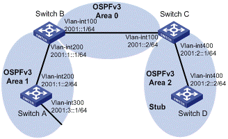
Figure 3-2 Network diagram for OSPFv3 area configuration
III. Configuration procedure
1) Configure IPv6 addresses for interfaces (omitted)
2) Configure OSPFv3 basic functions
# Configure Switch A.
<SwitchA> system-view
[SwitchA] ipv6
[SwitchA] ospfv3
[SwitchA-ospfv3-1] router-id 1.1.1.1
[SwitchA-ospfv3-1] quit
[SwitchA] interface vlan-interface 300
[SwitchA-Vlan-interface300] ospfv3 1 area 1
[SwitchA-Vlan-interface300] quit
[SwitchA] interface vlan-interface 200
[SwitchA-Vlan-interface200] ospfv3 1 area 1
[SwitchA-Vlan-interface200] quit
# Configure Switch B
<SwitchB> system-view
[SwitchB] ipv6
[SwitchB] ospfv3
[SwitchB-ospf-1] router-id 2.2.2.2
[SwitchB-ospf-1] quit
[SwitchB] interface vlan-interface 100
[SwitchB-Vlan-interface100] ospfv3 1 area 0
[SwitchB-Vlan-interface100] quit
[SwitchB] interface vlan-interface 200
[SwitchB-Vlan-interface200] ospfv3 1 area 1
[SwitchB-Vlan-interface200] quit
# Configure Switch C
<SwitchC> system-view
[SwitchC] ipv6
[SwitchC] ospfv3
[SwitchC-ospfv3-1] router-id 3.3.3.3
[SwitchC-ospfv3-1] quit
[SwitchC] interface vlan-interface 100
[SwitchC-Vlan-interface100] ospfv3 1 area 0
[SwitchC-Vlan-interface100] quit
[SwitchC] interface vlan-interface 400
[SwitchC-Vlan-interface400] ospfv3 1 area 2
[SwitchC-Vlan-interface400] quit
# Configure Switch D
<SwitchD> system-view
[SwitchD] ipv6
[SwitchD] ospfv3
[SwitchD-ospfv3-1] router-id 4.4.4.4
[SwitchD-ospfv3-1] quit
[SwitchD] interface Vlan-interface 400
[SwitchD-Vlan-interface400] ospfv3 1 area 2
[SwitchD-Vlan-interface400] quit
# Display OSPFv3 neighbor information on Switch B.
[SwitchB] display ospfv3 peer
OSPFv3 Area ID 0.0.0.0 (Process 1)
----------------------------------------------------------------------
Neighbor ID Pri State Dead Time Interface Instance ID
3.3.3.3 1 Full/DR 00:00:39 Vlan100 0
OSPFv3 Area ID 0.0.0.1 (Process 1)
----------------------------------------------------------------------
Neighbor ID Pri State Dead Time Interface Instance ID
1.1.1.1 1 Full/Backup 00:00:38 Vlan200 0
# Display OSPFv3 neighbor information on Switch C.
[SwitchC] display ospfv3 peer
OSPFv3 Area ID 0.0.0.0 (Process 1)
----------------------------------------------------------------------
Neighbor ID Pri State Dead Time Interface Instance ID
2.2.2.2 1 Full/Backup 00:00:39 Vlan100 0
OSPFv3 Area ID 0.0.0.2 (Process 1)
----------------------------------------------------------------------
Neighbor ID Pri State Dead Time Interface Instance ID
4.4.4.4 1 Full/DR 00:00:38 Vlan400 0
# Display OSPFv3 routing table information on Switch D.
[SwitchD] display ospfv3 routing
E1 - Type 1 external route, IA - Inter area route, I - Intra area route
E2 - Type 2 external route, * - Seleted route
OSPFv3 Router with ID (4.4.4.4) (Process 1)
------------------------------------------------------------------------
*Destination: 2001::/64
Type : IA Cost : 2
NextHop : FE80::F40D:0:93D0:1 Interface: Vlan400
*Destination: 2001:1::/64
Type : IA Cost : 3
NextHop : FE80::F40D:0:93D0:1 Interface: Vlan400
*Destination: 2001:2::/64
Type : I Cost : 1
NextHop : directly-connected Interface: Vlan400
*Destination: 2001:3::/64
Type : IA Cost : 4
NextHop : FE80::F40D:0:93D0:1 Interface: Vlan400
3) Configure Area 2 as a stub area
# Configure Switch D
[SwitchD] ospfv3
[SwitchD-ospfv3-1] area 2
[SwitchD-ospfv3-1-area-0.0.0.2] stub
# Configure Switch C, and specify the cost of the default route sent to the stub area as 10.
[SwitchC] ospfv3
[SwitchC-ospfv3-1] area 2
[SwitchC-ospfv3-1-area-0.0.0.2] stub
[SwitchC-ospfv3-1-area-0.0.0.2] default-cost 10
# Display OSPFv3 routing table information on Switch D. You can find a default route is added, whose cost is the cost of the directly connected route plus the configured cost.
[SwitchD] display ospfv3 routing
E1 - Type 1 external route, IA - Inter area route, I - Intra area route
E2 - Type 2 external route, * - Seleted route
OSPFv3 Router with ID (4.4.4.4) (Process 1)
------------------------------------------------------------------------
*Destination: ::/0
Type : IA Cost : 11
NextHop : FE80::F40D:0:93D0:1 Interface: Vlan400
*Destination: 2001::/64
Type : IA Cost : 2
NextHop : FE80::F40D:0:93D0:1 Interface: Vlan400
*Destination: 2001:1::/64
Type : IA Cost : 3
NextHop : FE80::F40D:0:93D0:1 Interface: Vlan400
*Destination: 2001:2::/64
Type : I Cost : 1
NextHop : directly-connected Interface: Vlan400
*Destination: 2001:3::/64
Type : IA Cost : 4
NextHop : FE80::F40D:0:93D0:1 Interface: Vlan400
4) Configure Area 2 as a totally stub area
# Configure Switch C, the ABR, to make Area 2 as a totally stub area.
[SwitchC-ospfv3-1-area-0.0.0.2] stub no-summary
# Display OSPFv3 routing table information on Switch D. You can find route entries are reduced. All non direct routes are removed except the default route.
[SwitchD] display ospfv3 routing
E1 - Type 1 external route, IA - Inter area route, I - Intra area route
E2 - Type 2 external route, * - Seleted route
OSPFv3 Router with ID (4.4.4.4) (Process 1)
------------------------------------------------------------------------
*Destination: ::/0
Type : IA Cost : 11
NextHop : FE80::F40D:0:93D0:1 Interface: Vlan400
*Destination: 2001:2::/64
Type : I Cost : 1
NextHop : directly-connected Interface: Vlan400
3.8.2 Configuring OSPFv3 DR Election
I. Network requirements
In the following figure:
l The priority of Switch A is 100, the highest priority on the network, so it will be the DR.
l The priority of Switch C is 2, the second highest priority on the network, so it will be the BDR.
l The priority of Switch B is 0, so it cannot become the DR.
l RouterD has the default priority 1.
II. Network diagram
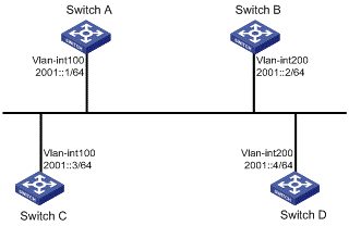
Figure 3-3 Network diagram for OSPFv3 DR election configuration
III. Configuration procedure
1) Configure IPv6 addresses for interfaces (omitted)
2) Configure OSPFv3 basic functions
# Configure Switch A
<SwitchA> system-view
[SwitchA] ipv6
[SwitchA] ospfv3
[SwitchA-ospfv3-1] router-id 1.1.1.1
[SwitchA-ospfv3-1] quit
[SwitchA] interface vlan-interface 100
[SwitchA-Vlan-interface100] ospfv3 1 area 0
[SwitchA-Vlan-interface100] quit
# Configure Switch B
<SwitchB> system-view
[SwitchB] ipv6
[SwitchB] ospfv3
[SwitchB-ospfv3-1] router-id 2.2.2.2
[SwitchB-ospfv3-1] quit
[SwitchB] interface vlan-interface 200
[SwitchB-Vlan-interface200] ospfv3 1 area 0
[SwitchB-Vlan-interface200] quit
# Configure Switch C
<SwitchC> system-view
[SwitchC] ipv6
[SwitchC] ospfv3
[SwitchC-ospfv3-1] router-id 3.3.3.3
[SwitchC-ospfv3-1] quit
[SwitchC] interface vlan-interface 100
[SwitchC-Vlan-interface100] ospfv3 1 area 0
[SwitchC-Vlan-interface100] quit
# Configure Switch D
<SwitchD> system-view
[SwitchD] ipv6
[SwitchD] ospfv3
[SwitchD-ospfv3-1] router-id 4.4.4.4
[SwitchD-ospfv3-1] quit
[SwitchD] interface vlan-interface 200
[SwitchD-Vlan-interface200] ospfv3 1 area 0
[SwitchD-Vlan-interface200] quit
# Display neighbor information on Switch A. You can find the switches have the same default DR priority 1. In this case, the switch with the highest Router ID is elected as the DR. Therefore, Switch D is the DR, and Switch C is the BDR.
[SwitchA] display ospfv3 peer
OSPFv3 Area ID 0.0.0.0 (Process 1)
----------------------------------------------------------------------
Neighbor ID Pri State Dead Time Interface Instance ID
2.2.2.2 1 2-Way/DROther 00:00:36 Vlan200 0
3.3.3.3 1 Full/Backup 00:00:35 Vlan100 0
4.4.4.4 1 Full/DR 00:00:33 Vlan200 0
# Display neighbor information on Switch D. You can find the neighbor states between Switch D and other switches are all full.
[SwitchD] display ospfv3 peer
OSPFv3 Area ID 0.0.0.0 (Process 1)
----------------------------------------------------------------------
Neighbor ID Pri State Dead Time Interface Instance ID
1.1.1.1 1 Full/DROther 00:00:30 Vlan100 0
2.2.2.2 1 Full/DROther 00:00:37 Vlan200 0
3.3.3.3 1 Full/Backup 00:00:31 Vlan100 0
3) Configure DR priorities for interfaces.
# Configure the DR priority of VLAN-interface 100 as 100 on Switch A.
[SwitchA] interface Vlan-interface 100
[SwitchA-Vlan-interface100] ospfv3 dr-priority 100
[SwitchA-Vlan-interface100] quit
# Configure the DR priority of VLAN-interface 200 as 0 on Switch B.
[SwitchB] interface vlan-interface 200
[SwitchB-Vlan-interface200] ospfv3 dr-priority 0
[SwitchB-Vlan-interface200] quit
#Configure the DR priority of Switch C as 2.
[SwitchC] interface Vlan-interface 100
[SwitchC-Vlan-interface100] ospfv3 dr-priority 2
[SwitchC-Vlan-interface100] quit
# Display neighbor information on Switch A. You can find DR priorities have been updated, but DR and BDR are not changed.
[SwitchA] display ospfv3 peer
OSPFv3 Area ID 0.0.0.0 (Process 1)
----------------------------------------------------------------------
Neighbor ID Pri State Dead Time Interface Instance ID
2.2.2.2 0 2-Way/DROther 00:00:38 Vlan200 0
3.3.3.3 2 Full/Backup 00:00:32 Vlan100 0
4.4.4.4 1 Full/DR 00:00:36 Vlan200 0
#Display neighbor information on Switch D. You can find Switch D is still the DR.
[SwitchD] display ospfv3 peer
OSPFv3 Area ID 0.0.0.0 (Process 1)
----------------------------------------------------------------------
Neighbor ID Pri State Dead Time Interface Instance ID
1.1.1.1 100 Full/DROther 00:00:33 Vlan100 0
2.2.2.2 0 Full/DROther 00:00:36 Vlan200 0
3.3.3.3 2 Full/Backup 00:00:40 Vlan100 0
4) Restart DR/BDR election
# Use the shutdown and undo shutdown commands on interfaces to restart DR/BDR election (omitted).
# Display neighbor information on Switch A. You can find Switch C becomes the BDR.
[SwitchA] display ospfv3 peer
OSPFv3 Area ID 0.0.0.0 (Process 1)
----------------------------------------------------------------------
Neighbor ID Pri State Dead Time Interface Instance ID
2.2.2.2 0 Full/DROther 00:00:31 Vlan200 0
3.3.3.3 2 Full/Backup 00:00:39 Vlan100 0
4.4.4.4 1 Full/DROther 00:00:37 Vlan200 0
# Display neighbor information on Switch D. You can find Switch A becomes the DR.
[SwitchD] display ospfv3 peer
OSPFv3 Area ID 0.0.0.0 (Process 1)
----------------------------------------------------------------------
Neighbor ID Pri State Dead Time Interface Instance ID
1.1.1.1 100 Full/DR 00:00:34 Vlan100 0
2.2.2.2 0 2-Way/DROther 00:00:34 Vlan200 0
3.3.3.3 2 Full/Backup 00:00:32 Vlan100 0
3.9 Troubleshooting OSPFv3 Configuration
3.9.1 No OSPFv3 Neighbor Relationship Established
I. Symptom
No OSPF neighbor relationship can be established.
II. Analysis
If the physical link and lower protocol work well, check OSPF parameters configured on interfaces. The two neighboring interfaces must have the same parameters, such as the area ID, network segment and mask, network type. If the network type is broadcast, at least one interface must have a DR priority higher than 0.
III. Process steps
1) Display neighbor information using the display ospfv3 peer command.
2) Display OSPFv3 interface information using the display ospfv3 interface command.
3) Ping the neighbor router’s IP address to check connectivity.
4) Check OSPF timers. The dead interval on an interface must be at least four times the hello interval.
5) On a broadcast network, at least one interface must have a DR priority higher than 0.
3.9.2 Incorrect Routing Information
I. Symptom
OSPFv3 cannot find routes to other areas.
II. Analysis
The backbone area must maintain connectivity to all other areas. If a router connects to more than one area, at least one area must be connected to the backbone. The backbone cannot be configured as a Stub area.
In a Stub area, all routers cannot receive external routes, and all interfaces connected to the Stub area must be associated with the Stub area.
III. Solution
1) Use the display ospfv3 peer command to display OSPFv3 neighbors.
2) Use the display ospfv3 interface command to display OSPFv3 interface information.
3) Use the display ospfv3 lsdb command to display Link State Database information to check integrity.
4) Display information about area configuration using the display current-configuration configuration command. If more than two areas are configured, at least one area is connected to the backbone.
5) In a Stub area, all routers are configured with the stub command.
6) If a virtual link is configured, use the display ospf vlink command to check the neighbor state.
Chapter 4 IPv6 IS-IS Configuration
& Note:
l IPv6 IS-IS supports all the features of IPv4 IS-IS except that it advertises IPv6 routing information instead. This document describes only IPv6 IS-IS exclusive configuration tasks. For other configuration tasks, refer to the part discussing IPv4 routing.
l The term “router” in this document refers to a Layer 3 switch running routing protocols.
When configuring IPv6 IS-IS, go to these sections for information you are interested in:
l Configuring IPv6 IS-IS Basic Functions
l Configuring IPv6 IS-IS Routing Information Control
l Displaying and Maintaining IPv6 IS-IS
l IPv6 IS-IS Configuration Example
4.1 Introduction to IPv6 IS-IS
The IS-IS routing protocol (Intermediate System-to-Intermediate System intra-domain routing information exchange protocol) supports multiple network protocols, including IPv6. IS-IS with IPv6 support is called IPv6 IS-IS dynamic routing protocol. The international engineer task force (IETF) defines two type-length-values (TLVs) and a new network layer protocol identifier (NLPID) to enable IPv6 support for IS-IS.
TLV is a variable field in the link state PDU or link state packet (LSP). The two TLVs are:
l IPv6 Reachability: Defines the prefix, metric of routing information to indicate the network reachability, with a type value of 236 (0xEC).
l IPv6 Interface Address: Similar with the “IP Interface Address” TLV of IPv4, it transforms the 32-bit IPv4 address to the 128-bit IPv6 address.
NLPID is an 8-bit field with a value of 142 (0x8E), which indicates the network layer protocol packet. If the IS-IS router supports IPv6, the advertised routing information must be marked with the NLPID.
4.2 Configuring IPv6 IS-IS Basic Functions
& Note:
You can implement IPv6 inter-networking through configuring IPv6 IS-IS in IPv6 network environment.
4.2.1 Configuration Prerequisites
Before the configuration, accomplish the following tasks first:
l Enable IPv6 globally
l Configure IP addresses for interfaces, and make sure all neighboring nodes are reachable.
l Enable IS-IS
4.2.2 Configuration Procedure
Follow these steps to configure the basic functions of IPv6 IS-IS:
|
To do... |
Use command to… |
Remarks |
|
Enter system view |
system-view |
–– |
|
Enable an IS-IS process and enter IS-IS view |
isis [ process-id ] |
Required Not enabled by default |
|
Configure the network entity title for the IS-IS process |
network-entity net |
Required Not configured by default |
|
Enable IPv6 for the IS-IS process |
ipv6 enable |
Required Disabled by default |
|
Return to system view |
quit |
–– |
|
Enter interface view |
interface interface-type interface-number |
–– |
|
Enable IPv6 for an IS-IS process on the interface |
isis ipv6 enable [ process-id ] |
Required Disabled by default |
4.3 Configuring IPv6 IS-IS Routing Information Control
4.3.1 Configuration Prerequisites
You need to complete the IPv6 IS-IS basic function configuration before configuring this task.
4.3.2 Configuration Procedure
Follow these steps to configure IPv6 IS-IS routing information control:
|
To do... |
Use command to… |
Remarks |
|
Enter system view |
system-view |
–– |
|
Enter IS-IS view |
isis [ process-id ] |
–– |
|
Define the priority for IPv6 IS-IS routes |
ipv6 preference { route-policy route-policy-name | preference } * |
Optional 15 by default |
|
Configure an IPv6 IS-IS summary route |
ipv6 summary ipv6-prefix prefix-length [ avoid-feedback | generate_null0_route | [ level-1 | level-1-2 | level-2 ] | tag tag ] * |
Optional Not configured by default |
|
Generate an IPv6 IS-IS default route |
ipv6 default-route-advertise [ [ level-1 | level-2 | level-1-2 ] | route-policy route-policy-name ]* |
Optional No IPv6 default route is defined by default. |
|
Configure IPv6 IS-IS to filter incoming routes |
ipv6 filter-policy { acl6-number | ipv6-prefix ipv6-prefix-name | route-policy route-policy-name } import |
Optional No filtering policy is defined by default |
|
Configure IPv6 IS-IS to redistribute routes from another routing protocol |
ipv6 import-route protocol [ process-id ] [ allow-ibgp ] [ cost cost-value | [ level-1 | level-2 | level-1-2 ] | route-policy route-policy-name | tag tag-value ] * |
Optional Not configured by default |
|
Configure the filtering of outgoing redistributed routes |
ipv6 filter-policy { acl6-number | ipv6-prefix ipv6-prefix-name | route-policy route-policy-name } export [ protocol [ process-id ] ] |
Optional Not configured by default |
|
Enable route leaking |
ipv6 import-route isisv6 level-2 into level-1 [ filter-policy { acl6-number | ipv6-prefix ipv6-prefix-name | route-policy route-policy-name } | tag tag ]* |
Optional Not enabled by default |
|
Specify the maximum number of equal-cost load balanced routes |
ipv6 maximum load-balancing number |
Optional 4 by default |
& Note:
The ipv6 filter-policy export command, usually used in combination with the ipv6 import-route command, filters redistributed routes when advertising them to other routers. If no protocol is specified, routes redistributed from all routing protocols are filtered before advertisement. If a protocol is specified, only routes redistributed from the routing protocol are filtered for advertisement.
4.4 Displaying and Maintaining IPv6 IS-IS
|
Use the command... |
Remarks |
|
|
Display brief IPv6 IS-IS information |
display isis brief |
Available in any view |
|
Display the status of the debug switches |
display isis debug-switches process-id |
Available in any view |
|
Display IS-IS enabled interface information |
display isis interface [ verbose ] process-id |
Available in any view |
|
Display IS-IS license information |
display isis license |
Available in any view |
|
Display LSDB information |
display isis lsdb [ [ l1 | l2 | level-1 | level-2 ] | [ [ lsp-id lsp-id | lsp-name lspname | local ] | verbose ] * ] * [ process-id ] |
Available in any view |
|
Display IS-IS mesh group information |
display isis mesh-group [ process-id ] |
Available in any view |
|
Display the mapping table between the host name and system ID |
display isis name-table [ process-id ] |
Available in any view |
|
Display IS-IS neighbor information |
display isis peer [ verbose ] [ process-id ] |
Available in any view |
|
Display IPv6 IS-IS routing information |
display isis route ipv6 [ [ level-1 | level-2 ] | verbose ] * [ process-id ] |
Available in any view |
|
Display SPF log information |
display isis spf-log [ process-id ] |
Available in any view |
|
Display the statistics of the IS-IS process |
display isis statistics [ level-1 | level-2 | level-1-2 ] [ process-id ] |
Available in any view |
|
Clear all IS-IS data structure information |
reset isis all [ process-id ] |
Available in user view |
|
Clear the IS-IS data information of a neighbor |
reset isis peer system-id [ process-id ] |
Available in user view |
4.5 IPv6 IS-IS Configuration Example
I. Network requirements
As shown in Figure 4-1, Switch A, Switch B, Switch C and Switch D reside in the same autonomous system, and all are enabled with IPv6.
Switch A and Switch B are Level-1 switches, Switch D is a Level-2 switch, and Switch C is a Level-1-2 switch. Switch A, Switch B, and Switch C are in area 10, while Switch D is in area 20.
II. Network diagram
Figure 4-1 Network diagram for IPv6 IS-IS basic configuration
III. Configuration procedure
1) Configure IPv6 addresses for interfaces (omitted)
2) Configure IPv6 IS-IS
# Configure Switch A.
<SwitchA> system-view
[SwitchA] isis 1
[SwitchA-isis-1] is-level level-1
[SwitchA-isis-1] network-entity 10.0000.0000.0001.00
[SwitchA-isis-1] ipv6 enable
[SwitchA-isis-1] quit
[SwitchA] interface vlan-interface 100
[SwitchA-Vlan-interface100] isis ipv6 enable 1
[SwitchA-Vlan-interface100] quit
# Configure Switch B.
<SwitchB> system-view
[SwitchB] isis 1
[SwitchB-isis-1] is-level level-1
[SwitchB-isis-1] network-entity 10.0000.0000.0002.00
[SwitchB-isis-1] ipv6 enable
[SwitchB-isis-1] quit
[SwitchB] interface vlan-interface 200
[SwitchB-Vlan-interface200] isis ipv6 enable 1
[SwitchB-Vlan-interface200] quit
# Configure Switch C.
<SwitchC> system-view
[SwitchC] isis 1
[SwitchC-isis-1] network-entity 10.0000.0000.0003.00
[SwitchC-isis-1] ipv6 enable
[SwitchC-isis-1] quit
[SwitchC] interface vlan-interface 100
[SwitchC-Vlan-interface100] isis ipv6 enable 1
[SwitchC-Vlan-interface100] quit
[SwitchC] interface vlan-interface 200
[SwitchC-Vlan-interface200] isis ipv6 enable 1
[SwitchC-Vlan-interface200] quit
[SwitchC] interface vlan-interface 300
[SwitchC-Vlan-interface300] isis ipv6 enable 1
[SwitchC-Vlan-interface300] quit
# Configure Switch D.
<SwitchD> system-view
[SwitchD] isis 1
[SwitchD-isis-1] is-level level-2
[SwitchD-isis-1] network-entity 20.0000.0000.0004.00
[SwitchD-isis-1] ipv6 enable
[SwitchD-isis-1] quit
[SwitchD] interface vlan-interface 300
[SwitchD-Vlan-interface300] isis ipv6 enable 1
[SwitchD-Vlan-interface300] quit
[SwitchD] interface vlan-interface 301
[SwitchD-Vlan-interface301] isis ipv6 enable 1
[SwitchD-Vlan-interface301] quit
Chapter 5 IPv6 BGP Configuration
& Note:
This chapter describes only configuration for IPv6 BGP. For other related information, refer to the part discussing IPv4 routing.
When configuring IPv6 BGP, go to these sections for information you are interested in:
l Configuring IPv6 BGP Basic Functions
l Controlling Route Distribution and Reception
l Configuring IPv6 BGP Route Attributes
l Tuning and Optimizing IPv6 BGP Networks
l Configuring a Large Scale IPv6 BGP Network
l Displaying and Maintaining IPv6 BGP Configuration
l IPv6 BGP Configuration Examples
l Troubleshooting IPv6 BGP Configuration
5.1 IPv6 BGP Overview
BGP-4 manages only IPv4 routing information, thus other network layer protocols such as IPv6 are not supported.
To support multiple network layer protocols, IETF extended BGP-4 by introducing IPv6 BGP that is defined in RFC 2858 (multiprotocol extensions for BGP-4).
To implement IPv6 support, IPv6 BGP puts IPv6 network layer information into the attributes of network layer reachable information (NLRI) and NEXT_HOP.
NLRI attribute of IPv6 BGP involves:
l MP_REACH_NLRI: Multiprotocol Reachable NLRI, for advertisement of next hop information of reachable routes.
l MP_UNREACH_NLRI: Multiprotocol Unreachable NLRI, for withdrawal of unreachable routes.
The NEXT_HOP attribute of IPv6 BGP is identified by an IPv6 unicast address or IPv6 local link address.
IPv6 BGP utilizes BGP multiprotocol extensions for application in IPv6 networks. The original messaging and routing mechanisms of BGP are not changed.
5.2 Configuration Task List
Complete the following tasks to configure IPv6 BGP:
|
Task |
Remarks |
|
|
Required |
||
|
Optional |
||
|
Configuring a Preferred Value for Routes from a Peer/Peer Group |
Optional |
|
|
Specifying the Source Interface for Establishing TCP Connections |
Optional |
|
|
Optional |
||
|
Optional |
||
|
Optional |
||
|
Optional |
||
|
Optional |
||
|
Optional |
||
|
Optional |
||
|
Optional |
||
|
Optional |
||
|
Optional |
||
|
Configuring IPv6 BGP Preference and Default LOCAL_PREF and NEXT_HOP Attributes |
Optional |
|
|
Optional |
||
|
Optional |
||
|
Optional |
||
|
Optional |
||
|
Optional |
||
|
Optional |
||
|
Optional |
||
|
Optional |
||
5.3 Configuring IPv6 BGP Basic Functions
5.3.1 Prerequisites
Before configuring this task, you need to:
l Specify IP addresses for interfaces.
l Enable IPv6.
& Note:
You need create a peer group before configuring basic functions for it. For related information, refer to Configuring IPv6 BGP Peer Group.
5.3.2 Configuring an IPv6 Peer
Follow these steps to configure an IPv6 peer:
|
To do... |
Use the command... |
Remarks |
|
Enter system view |
system-view |
— |
|
Enter BGP view |
bgp as-number |
Required Not enabled by default |
|
Specify a router ID |
router-id router-id |
Optional Required if no IP addresses configured for Loopback interface and other interfaces |
|
Enter IPv6 address family view |
ipv6-family |
— |
|
Specify an IPv6 peer and its AS number |
peer ipv6-address as-number as-number |
Required Not configured by default |
5.3.3 Advertising a Local IPv6 Route
Follow these steps to configure advertise a local route into the routing table:
|
To do... |
Use the command... |
Remarks |
|
Enter system view |
system-view |
— |
|
Enter BGP view |
bgp as-number |
Required |
|
Enter IPv6 address family view |
ipv6-family |
— |
|
Add a local route into IPv6 BGP routing table |
network ipv6-address prefix-length [ short-cut | route-policy route-policy-name ] |
Required Not added by default |
5.3.4 Configuring a Preferred Value for Routes from a Peer/Peer Group
Follow these steps to configure a preferred value for routes received from a peer/peer group:
|
To do... |
Use the command... |
Remarks |
|
Enter system view |
system-view |
— |
|
Enter BGP view |
bgp as-number |
Required |
|
Enter IPv6 address family view |
ipv6-family |
— |
|
Configure a preferred value for routes received from a peer/peer group |
peer { ipv6-group-name | ipv6-address } preferred-value value |
Optional By default, the preferred value is 0. |
& Note:
If you both reference a routing policy and use the command peer { ipv6-group-name | ipv6-address } preferred-value value to set a preferred value for routes from a peer, the routing policy sets a non-zero preferred value for routes matching it. Other routes not matching the routing policy uses the value set with the command. If the preferred value in the routing policy is zero, the routes matching it will also use the value set with the command. For information about using a routing policy to set a preferred value, refer to the peer { ipv6-group-name | ipv6-address } route-policy route-policy-name { import | export } command and the apply preferred-value preferred-value command.
5.3.5 Specifying the Source Interface for Establishing TCP Connections
Follow these steps to specify the source interface for establishing TCP connections to a BGP peer or peer group:
|
To do... |
Use the command... |
Remarks |
|
Enter system view |
system-view |
— |
|
Enter BGP view |
bgp as-number |
Required |
|
Enter IPv6 address family view |
ipv6-family |
— |
|
Specify the source interface for establishing TCP connections to a BGP peer or peer group |
peer { ipv6-group-name | ipv6-address } connect-interface interface-type interface-number |
Required By default, IPv6 BGP uses the outbound interface of the best route to the BGP peer as the source interface for establishing a TCP connection. |
& Note:
l To improve stability and reliability, you can specify a loopback interface as the source interface for establishing TCP connections to a BGP peer. By doing so, a connection failure upon redundancy availability will not affect TCP connection establishment.
l To establish multiple BGP connections to a BGP router, you need to specify on the local router the respective source interfaces for establishing TCP connections to the peers on the peering BGP router; otherwise, the local BGP router may fail to establish TCP connections to the peers when using the outbound interfaces of the best routes as the source interfaces.
5.3.6 Allowing the establishment of a Non-Direct EBGP connection
Follow these steps to allow the establishment of EBGP connection to a non-directly connected peer/peer group:
|
To do... |
Use the command... |
Remarks |
|
Enter system view |
system-view |
— |
|
Enter BGP view |
bgp as-number |
Required |
|
Enter IPv6 address family view |
ipv6-family |
— |
|
Allow the establishment of EBGP connection to a non directly connected peer/peer group |
peer { ipv6-group-name | ipv6-address } ebgp-max-hop [ hop-count ] |
Required Not configured by default |
![]() Caution:
Caution:
In general, direct links should be available between EBGP peers. If not, you can use the peer ebgp-max-hop command to establish a multi-hop TCP connection in between. However, you need not use this command for direct EBGP connection with loopback interfaces.
5.3.7 Configuring a Description for a Peer/Peer Group
Follow these steps to configure description for a peer/peer group:
|
To do... |
Use the command... |
Remarks |
|
Enter system view |
system-view |
— |
|
Enter BGP view |
bgp as-number |
Required |
|
Enter IPv6 address family view |
ipv6-family |
— |
|
Configure a description for a peer/peer group |
peer { ipv6-group-name | ipv6-address } description description-text |
Optional Not configured by default |
& Note:
The peer group to be configured with a description must have been created.
5.3.8 Disabling Session Establishment to a Peer/Peer Group
Follow these steps to disable session establishment to a peer/peer group:
|
To do... |
Use the command... |
Remarks |
|
Enter system view |
system-view |
— |
|
Enter BGP view |
bgp as-number |
Required |
|
Enter IPv6 address family view |
ipv6-family |
— |
|
Disable session establishment to a peer/peer group |
peer { ipv6-group-name | ipv6-address } ignore |
Optional Not disabled by default |
5.3.9 Logging Peer State Changes
Follow these steps to configure to log on the session and event information of a peer/peer group:
|
To do... |
Use the command... |
Remarks |
|
Enter system view |
system-view |
— |
|
Enter BGP view |
bgp as-number |
Required |
|
Enable logging of peer changes globally |
log-peer-change |
Optional Enabled by default |
|
Enter IPv6 address family view |
ipv6-family |
— |
|
Enable the state change logging for a peer or peer group |
peer { ipv6-group-name | ipv6-address } log-change |
Optional Enabled by default |
& Note:
Refer to the part discussing IPv4 routing commands for information about the log-peer-change command.
5.4 Controlling Route Distribution and Reception
The task includes routing information filtering, routing policy application and route dampening.
5.4.1 Prerequisites
Before configuring this task, you have:
l Enabled the IPv6 function
l Configured the IPv6 BGP basic functions
5.4.2 Configuring IPv6 BGP Route Redistribution
Follow these steps to configure IPv6 BGP route redistribution and filtering:
|
To do... |
Use the command... |
Remarks |
|
Enter system view |
system-view |
— |
|
Enter BGP view |
bgp as-number |
— |
|
Enter IPv6 address family view |
ipv6-family |
— |
|
Enable default route redistribution into the IPv6 BGP routing table |
default-route imported |
Optional Not enabled by default |
|
Enable route redistribution from another routing protocol |
import-route protocol [ process-id ] [ med med-value | route-policy route-policy-name ]* |
Required Not enabled by default |
& Note:
If the default-route imported command is not configured, using the import-route command cannot redistribute any IGP default route.
5.4.3 Advertising a Default Route to a Peer/Peer Group
Follow these steps to configure to advertise default route to a peer/peer group:
|
To do... |
Use the command... |
Remarks |
|
Enter system view |
system-view |
— |
|
Enter BGP view |
bgp as-number |
Required |
|
Enter IPv6 address family view |
ipv6-family |
— |
|
Advertise a default route to a peer/peer group |
peer { ipv6-group-name | ipv6-address } default-route-advertise [ route-policy route-policy-name ] |
Required Not advertised by default |
& Note:
With the peer default-route-advertise command used, the local router advertises a default route with itself as the next hop to the specified peer/peer group, regardless of whether the default route is available in the routing table.
5.4.4 Configuring Route Distribution Policy
Follow these steps to configure policies for route distribution:
|
To do... |
Use the command... |
Remarks |
|
Enter system view |
system-view |
— |
|
Enter BGP view |
bgp as-number |
Required |
|
Enter IPv6 address family view |
ipv6-family |
— |
|
Configure outbound route filtering |
filter-policy { acl6-number | ipv6-prefix ipv6-prefix-name } export [ protocol process-id ] |
Required Not configured by default |
|
Apply a routing policy to routes advertised to a peer/peer group |
peer { ipv6-group-name | ipv6-address } route-policy route-policy-name export |
Required Not applied by default |
|
Specify an IPv6 ACL to filer routes advertised to a peer/peer group |
peer { ipv6-group-name | ipv6-address } filter-policy acl6-number export |
Required Not specified by default |
|
Specify an AS path ACL to filer routes advertised to a peer/peer group |
peer { ipv6-group-name | ipv6-address } as-path-acl as-path-acl-number export |
Required Not specified by default |
|
Specify an IPv6 prefix list to filer routes advertised to a peer/peer group |
peer { ipv6-group-name | ipv6-address } ipv6-prefix ipv6-prefix-name export |
Required Not specified by default |
& Note:
l Members of a peer group must have the same outbound route policy with the peer group.
l IPv6 BGP advertises routes passing the specified policy to peers. Using the protocol argument can filter only the specified protocol routes. If no protocol specified, IPv6 BGP filters all routes to be advertised, including redistributed routes and routes imported using the network command.
5.4.5 Configuring Route Reception Policy
Follow these steps to configure route reception policy:
|
To do... |
Use the command... |
Remarks |
|
Enter system view |
system-view |
— |
|
Enter BGP view |
bgp as-number |
— |
|
Enter IPv6 address family view |
ipv6-family |
— |
|
Configure inbound route filtering |
filter-policy { acl6-number | ipv6-prefix ipv6-prefix-name } import |
Required Not configured by default |
|
Apply a routing policy to routes from a peer/peer group |
peer { ipv6-group-name | ipv6-address } route-policy route-policy-name import |
Required Not applied by default |
|
Specify an ACL to filter routes imported from a peer/peer group |
peer { ipv6-group-name | ipv6-address } filter-policy acl6-number import |
Required Not specified by default |
|
Specify an AS path ACL to filter routing information imported from a peer/peer group |
peer { ipv6-group-name | ipv6-address } as-path-acl as-path-acl-number import |
Required Not specified by default |
|
Specify an IPv6 prefix list to filter routing information imported from a peer/peer group |
peer { ipv6-group-name | ipv6-address } ipv6-prefix ipv6-prefix-name import |
Required Not specified by default |
|
Specify the upper limit of address prefixes imported from a peer/peer group |
peer { ipv6-group-name | ipv6-address } route-limit limit [ percentage ] |
Optional By default, no limit on prefixes |
& Note:
l Only routes passing the specified policy can be added into the local IPv6 BGP routing table.
l Members of a peer group can have different inbound route policies.
5.4.6 Configuring IPv6 BGP and IGP Route Synchronization
With this feature enabled and when a non-BGP router is responsible for forwarding packets in an AS, IPv6 BGP speakers in the AS cannot advertise routing information to outside ASs unless all routers in the AS know the latest routing information.
By default, when a BGP router receives an IBGP route, it only checks the reachability of the route’s next hop before advertisement. If the synchronization feature is configured, only the IBGP route is advertised by IGP can the route be advertised to EBGP peers.
Follow these steps to configure IPv6 BGP and IGP route synchronization:
|
To do... |
Use the command... |
Remarks |
|
Enter system view |
system-view |
— |
|
Enter BGP view |
bgp as-number |
Required |
|
Enter IPv6 address family view |
ipv6-family |
— |
|
Enable route synchronization between IPv6 BGP and IGP |
synchronization |
Required Not enabled by default |
5.4.7 Configuring Route Dampening
Follow these steps to configure BGP route dampening:
|
To do... |
Use the command... |
Remarks |
|
Enter system view |
system-view |
— |
|
Enter BGP view |
bgp as-number |
Required |
|
Enter IPv6 address family view |
ipv6-family |
— |
|
Configure IPv6 BGP route dampening parameters |
dampening [ half-life-reachable half-life-unreachable reuse suppress ceiling | route-policy route-policy-name ]* |
Optional Not configured by default |
5.5 Configuring IPv6 BGP Route Attributes
This section describes how to use IPv6 BGP route attributes to modify BGP routing policy. These attributes are:
l IPv6 BGP protocol preference
l Default LOCAL_PREF attribute
l MED attribute
l NEXT_HOP attribute
l AS_PATH attribute
5.5.1 Prerequisites
Before configuring this task, you have:
l Enabled IPv6 function
l Configured IPv6 BGP basic functions
5.5.2 Configuring IPv6 BGP Preference and Default LOCAL_PREF and NEXT_HOP Attributes
Follow these steps to perform this configuration:
|
To do... |
Use the command... |
Remarks |
|
Enter system view |
system-view |
— |
|
Enter BGP view |
bgp as-number |
Required |
|
Enter IPv6 address family view |
ipv6-family |
— |
|
Configure preference values for IPv6 BGP external, internal, local routes |
preference { external-preference internal-preference local-preference | route-policy route-policy-name } |
Optional The default preference values of external, internal and local routes are 255, 255, 130 respectively |
|
Configure the default value for local preference |
default local-preference value |
Optional The value defaults to 100 |
|
Advertise routes to a peer/peer group with the local router as the next hop |
peer { ipv6-group-name | ipv6-address } next-hop-local |
Required By default, the feature is available for routes advertised to the EBGP peer/peer group, but not available to the IBGP peer/peer group |
& Note:
l To make sure an IBGP peer can find the correct next hop, you can configure routes advertised to the peer to use the local router as the next hop. If BGP load balancing is configured, the local router specifies itself as the next hop of outbound routes to a peer/peer group regardless of whether the peer next-hop-local command is configured.
l In a “third party next hop" network, that is, the two EBGP peers reside in a common broadcast subnet, the router does not specify itself as the next hop for routes to the EBGP peer by default, unless the peer next-hop-local command is configured.
5.5.3 Configuring the MED Attribute
Follow these steps to configure the MED attribute:
|
To do... |
Use the command... |
Remarks |
|
Enter system view |
system-view |
— |
|
Enter BGP view |
bgp as-number |
Required |
|
Enter IPv6 address family view |
ipv6-family |
— |
|
Configure a default MED value |
default med med-value |
Optional Defaults to 0 |
|
Enable to compare MED values of routes from different EBGP peers |
compare-different-as-med |
Optional Not enabled by default |
|
Prioritize MED values of routes from each AS |
bestroute compare-med |
Optional Not configured by default |
|
Prioritize MED values of routes from confederation peers |
bestroute med-confederation |
Optional Not configured by default |
5.5.4 Configuring the AS_PATH Attribute
Follow these steps to configure the AS_PATH attribute:
|
To do... |
Use the command... |
Remarks |
|
Enter system view |
system-view |
— |
|
Enter BGP view |
bgp as-number |
Required |
|
Enter IPv6 address family view |
ipv6-family |
— |
|
Allow the local AS number to appear in AS_PATH of routes from a peer/peer group and specify the repeat times |
peer { ipv6-group-name | ipv6-address } allow-as-loop [ number ] |
Optional Not allowed by default |
|
Specify a fake AS number for a peer/peer group |
peer { ipv6-group-name | ipv6-address } fake-as as-number |
Optional Not specified by default |
|
Neglect the AS_PATH attribute for best route selection |
bestroute as-path-neglect |
Optional Not neglected by default |
|
Configure to carry only the public AS number in updates sent to a peer/peer group |
peer { ipv6-group-name | ipv6-address } public-as-only |
Optional By default, BGP updates carry private AS number |
|
Substitute local AS number for the AS number of a peer/peer group indicated in the AS_PATH attribute |
peer { ipv6-group-name | ipv6-address } substitute-as |
Optional Not substituted by default |
5.6 Tuning and Optimizing IPv6 BGP Networks
This section describes configurations of IPv6 BGP timers, IPv6 BGP connection soft reset and the maximum number of load balanced routes.
l IPv6 BGP timers
After establishing an IPv6 BGP connection, two routers send keepalive messages periodically to each other to keep the connection. If a router receives no keepalive message from the peer after the holdtime elapses, it tears down the connection.
When establishing an IPv6 BGP connection, the two parties compare their holdtime values, taking the shorter one as the common holdtime. If the holdtime is 0, neither keepalive massage is sent, nor holdtime is checked.
l IPv6 BGP connection soft reset
After modifying a route selection policy, you have to reset IPv6 BGP connections to make the new one take effect, causing a short time disconnection. The current IPv6 BGP implementation supports the route-refresh feature that enables dynamic IPv6 BGP routing table refresh without needing to disconnect IPv6 BGP links.
With this feature enabled on all IPv6 BGP routers in a network, when a routing policy modified on a router, the router advertises a route-refresh message to its peers, which then send their routing information back to the router. Therefore, the local router can perform dynamic routing information update and apply the new policy without tearing down connections.
If a router not supporting route-refresh exists in the network, you need to configure the peer keep-all-routes command on the router to save all route updates, and then use the refresh bgp ipv6 command to soft-reset IPv6 BGP connections.
5.6.1 Prerequisites
Before configuring IPv6 BGP timers, you have:
l Enabled IPv6 function
l Configured IPv6 BGP basic functions
5.6.2 Configuring IPv6 BGP Timers
Follow these steps to configure IPv6 BGP timers:
|
To do... |
Use the command... |
Remarks |
|
|
Enter system view |
system-view |
— |
|
|
Enter BGP view |
bgp as-number |
Required |
|
|
Enter IPv6 address family view |
ipv6-family |
— |
|
|
Configure IPv6 BGP timers |
Specify keepalive interval and holdtime |
timer keepalive keepalive hold holdtime |
Optional The keepalive interval defaults to 60 seconds, holdtime defaults to 180 seconds. |
|
Configure keepalive interval and holdtime for a peer/peer group |
peer { ipv6-group-name | ipv6-address } timer keepalive keepalive hold holdtime |
||
|
Configure the interval for sending the same update to a peer/peer group |
peer { ipv6-group-name | ipv6-address } route-update-interval seconds |
Optional The interval for sending the same update to an IBGP peer or an EBGP peer defaults to 15 seconds or 30 seconds |
|
& Note:
l Timers configured using the timer command have lower priority than timers configured using the peer timer command.
l The holdtime interval must be at least three times the keepalive interval.
5.6.3 Configuring IPv6 BGP Soft Reset
I. Enable route refresh
Follow these steps to enable route refresh:
|
To do... |
Use the command... |
Remarks |
|
Enter system view |
system-view |
— |
|
Enter BGP view |
bgp as-number |
Required |
|
Enter IPv6 address family view |
ipv6-family |
— |
|
Enable route refresh |
peer { ipv6-group-name | ipv6-address } capability-advertise route-refresh |
Optional Enabled by default |
II. Perform manual soft-reset
Follow these steps to perform manual soft reset:
|
To do... |
Use the command... |
Remarks |
|
Enter system view |
system-view |
— |
|
Enter BGP view |
bgp as-number |
Required |
|
Enter IPv6 address family view |
ipv6-family |
— |
|
Save all routes from a peer/peer group, not letting them go through the inbound policy |
peer { ipv6-group-name | ipv6-address } keep-all-routes |
Optional Not saved by default. |
|
Return to user view |
return |
Required |
|
Soft-reset BGP connections manually |
refresh bgp ipv6 { all | ipv6-address | group ipv6-group-name | external | internal } { export | import } |
& Note:
If the peer keep-all-routes command is used, all routes from the peer/peer group will be saved regardless of whether the filtering policy is available. These routes will be used to generate IPv6 BGP routes after soft-reset is performed.
5.6.4 Configuring the Maximum Number of Load-Balanced Routes
Follow these steps to configure the maximum number of load balanced routes:
|
To do... |
Use the command... |
Remarks |
|
Enter system view |
system-view |
— |
|
Enter BGP view |
bgp as-number |
Required |
|
Enter IPv6 address family view |
ipv6-family |
— |
|
Configure the maximum number of load balanced routes |
balance number |
Required By default, no load balancing is enabled. |
5.7 Configuring a Large Scale IPv6 BGP Network
In a large-scale IPv6 BGP network, configuration and maintenance become no convenient due to too many peers. In this case, configuring peer groups makes management easier and improves route distribution efficiency. Peer group includes IBGP peer group, where peers belong to the same AS, and EBGP peer group, where peers belong to different ASs. If peers in an EBGP group belong to the same external AS, the EBGP peer group is a pure EBGP peer group, and if not, a mixed EBGP peer group.
In a peer group, all members enjoy a common policy. Using the community attribute can make a set of IPv6 BGP routers in multiple ASs enjoy the same policy, because sending of community between IPv6 BGP peers is not limited by AS.
To guarantee connectivity between IBGP peers, you need to make them fully meshed, but it becomes unpractical when there are too many IBGP peers. Using route reflectors or confederation can solve it. In a large-scale AS, both of them can be used.
Confederation configuration of IPv6 BGP is identical to that of BGP4, so it is not mentioned here. The following describes:
l Configuring IPv6 BGP peer group
l Configuring IPv6 BGP community
l Configuring IPv6 BGP route reflector
5.7.1 Prerequisites
Before configuring IPv6 BGP peer group, you have:
l Made peer nodes accessible at network layer
l Enabled BGP and configured router ID.
5.7.2 Configuring IPv6 BGP Peer Group
I. Create an IBGP peer group
Follow these steps to create an IBGP group:
|
To do... |
Use the command... |
Remarks |
|
Enter system view |
system-view |
— |
|
Enter BGP view |
bgp as-number |
Required Not enabled by default |
|
Enter IPv6 address family view |
ipv6-family |
— |
|
Create an IBGP peer group |
group ipv6-group-name [ internal ] |
Required |
|
Add a peer into the group |
peer ipv6-address group ipv6-group-name [ as-number as-number ] |
Required Not added by default |
II. Create a pure EBGP peer group
Follow these steps to configure a pure EBGP group:
|
To do... |
Use the command... |
Remarks |
|
Enter system view |
system-view |
— |
|
Enter BGP view |
bgp as-number |
Required Not enabled by default |
|
Enter IPv6 address family view |
ipv6-family |
— |
|
Create an EBGP peer group |
group ipv6-group-name external |
Required |
|
Configure the AS number for the peer group |
peer ipv6-group-name as-number as-number |
Required Not configured by default |
|
Add an IPv6 peer into the peer group |
peer ipv6-address group ipv6-group-name |
Required Not added by default |
& Note:
l To create a pure EBGP peer group, you need to specify an AS number for the peer group.
l If a peer was added into an EBGP peer group, you cannot specify any AS number for the peer group.
III. Create a mixed EBGP peer group
Follow these steps to create a mixed EBGP peer group:
|
To do... |
Use the command... |
Remarks |
|
Enter system view |
system-view |
— |
|
Enter BGP view |
bgp as-number |
Required Not enabled by default |
|
Enter IPv6 address family view |
ipv6-family |
— |
|
Create an EBGP peer group |
group ipv6-group-name external |
Required |
|
Specify the AS number of an IPv6 peer |
peer ipv6-address as-number as-number |
Required Not specified by default |
|
Add the IPv6 peer into the peer group |
peer ipv6-address group ipv6-group-name |
Required Not added by default |
& Note:
When creating a mixed EBGP peer group, you need to create a peer and specify its AS number that can be different from AS numbers of other peers, but you cannot specify AS number for the EBGP peer group.
5.7.3 Configuring IPv6 BGP Community
I. Advertise community attribute to a peer/peer group
Follow these steps to advertise community attribute to a peer/peer group:
|
Use the command... |
Remarks |
|
|
Enter system view |
system-view |
— |
|
Enter BGP view |
bgp as-number |
Required Not enabled by default |
|
Enter IPv6 address family view |
ipv6-family |
— |
|
Advertise community attribute to a peer/peer group |
peer { ipv6-group-name | ipv6-address } advertise-community |
Required Not advertised by default |
|
Advertise extended community attribute to a peer/peer group |
peer { ipv6-group-name | ipv6-address } advertise-ext-community |
Required Not advertised by default |
II. Apply a routing policy to routes advertised to a peer/peer group
Follow these steps to apply a routing policy to routes advertised to a peer/peer group:
|
To do... |
Use the command... |
Remarks |
|
Enter system view |
system-view |
— |
|
Enter BGP view |
bgp as-number |
Required |
|
Enter IPv6 address family view |
ipv6-family |
— |
|
Apply a routing policy to routes advertised to a peer/peer group |
peer { ipv6-group-name | ipv6-address } route-policy route-policy-name export |
Required Not applied by default |
& Note:
When configuring IPv6 BGP community, you need to configure a routing policy to define the community attribute, and apply the routing policy to route advertisement.
5.7.4 Configuring an IPv6 BGP Route Reflector
Follow these steps to configure an IPv6 BGP route reflector:
|
Use the command... |
Remarks |
|
|
Enter system view |
system-view |
— |
|
Enter BGP view |
bgp as-number |
Required |
|
Enter IPv6 address family view |
ipv6-family |
— |
|
Configure the router as a route reflector and specify a peer/peer group as a client |
peer { ipv6-group-name | ipv6-address } reflect-client |
Required Not configured by default |
|
Enable route reflection between clients |
reflect between-clients |
Optional Enabled by default |
|
Configure the cluster ID of the route reflector |
reflector cluster-id cluster-id |
Optional By default, a route reflector uses its router ID as the cluster ID |
& Note:
l In general, since the route reflector forwards routing information between clients, it is not required to make clients of a route reflector fully meshed. If clients are fully meshed, it is recommended to disable route reflection between clients to reduce routing costs.
l If a cluster has multiple route reflectors, you need to specify the same cluster ID for these route reflectors to avoid routing loops.
5.8 Displaying and Maintaining IPv6 BGP Configuration
5.8.1 Displaying BGP
|
To do... |
Use the command... |
Remarks |
|
Display IPv6 BGP peer group information |
display bgp ipv6 group [ ipv6-group-name ] |
Available in any view |
|
Display IPv6 BGP advertised routing information |
display bgp ipv6 network |
|
|
Display IPv6 BGP AS path information |
display bgp ipv6 paths [ as-regular-expression ] |
|
|
Display IPv6 BGP peer/peer group information |
display bgp ipv6 peer [ ipv6-group-name log-info | ipv6-address { log-info | verbose } ] |
|
|
Display IPv6 BGP routing table information |
display bgp ipv6 routing-table [ ipv6-address prefix-length ] |
|
|
Display IPv6 BGP routing information matching an AS path ACL |
display bgp ipv6 routing-table as-path-acl as-path-acl-number |
|
|
Display IPv6 BGP community routing information |
display bgp ipv6 routing-table community [ aa:nn<1-13> ] [ no-advertise | no-export | no-export-subconfed ]* [ whole-match ] |
|
|
Display IPv6 BGP routing information matching an IPv6 BGP community list |
display bgp ipv6 routing-table community-list { basic-community-list-number [ whole-match ] | adv-community-list-number }&<1-16> |
|
|
Display dampened IPv6 BGP routing information |
||
|
Display IPv6 BGP dampening parameter information |
display bgp ipv6 routing-table dampening parameter |
|
|
Display IPv6 BGP routing information originated from different ASs |
display bgp ipv6 routing-table different-origin-as |
|
|
Display IPv6 BGP routing flap statistics |
display bgp ipv6 routing-table flap-info [ regular-expression as-regular-expression | as-path-acl as-path-acl-number | network-address [ prefix-length [ longer-match ] ] ] |
|
|
Display BGP routing information to or from an IPv6 peer |
display bgp ipv6 routing-table peer ipv6-address { advertised-routes | received-routes } [ network-address prefix-length | statistic ] |
|
|
Display IPv6 BGP routing information matching a regular expression |
display bgp ipv6 routing-table regular-expression as-regular-expression |
|
|
Display IPv6 BGP routing statistics |
display bgp ipv6 routing-table statistic |
5.8.2 Resetting IPv6 BGP Connections
|
To do... |
Use the command... |
Remarks |
|
Perform soft reset on IPv6 BGP connections |
refresh bgp ipv6 { ipv6-address | all | external | group ipv6-group-name | internal } { export | import } |
Available in user view |
|
Reset IPv6 BGP connections |
reset bgp ipv6 { as-number | ipv6-address [ flap-info ] | all | group ipv6-group-name | external | internal } |
5.8.3 Clearing IPv6 BGP Information
|
To do... |
Use the command... |
Remarks |
|
Clear dampened IPv6 BGP routing information and release suppressed routes |
reset bgp ipv6 dampening [ ipv6-address prefix-length ] |
Available in user view |
|
Clear IPv6 BGP route flap information |
reset bgp ipv6 flap-info [ ipv6-address/prefix-length | regexp as-path-regexp | as-path-acl as-path-acl-number ] |
5.9 IPv6 BGP Configuration Examples
& Note:
Some examples for IPv6 BGP configuration are similar to those of BGP-4, so refer to the sections covering BGP in the IPv4 routing part for related information.
5.9.1 IPv6 BGP Basic Configuration
I. Network requirements
In the following figure are all IPv6 BGP switches. Between Switch A and Switch B is an EBGP connection. Switch B, Switch C and Switch D are IBGP fully meshed.
II. Network diagram
Figure 5-1 IPv6 BGP basic configuration network diagram
III. Configuration procedure
1) Configure IPv6 addresses for interfaces (omitted)
2) Configure IBGP connections
# Configure Switch B.
<SwitchB> system-view
[SwitchB] ipv6
[SwitchB] bgp 65009
[SwitchB-bgp] router-id 2.2.2.2
[SwitchB-bgp] ipv6-family
[SwitchB-bgp-af-ipv6] peer 9:1::2 as-number 65009
[SwitchB-bgp-af-ipv6] peer 9:3::2 as-number 65009
[SwitchB-bgp-af-ipv6] quit
[SwitchB-bgp] quit
# Configure Switch C.
<SwitchC> system-view
[SwitchC] ipv6
[SwitchC] bgp 65009
[SwitchC-bgp] router-id 3.3.3.3
[SwitchC-bgp] ipv6-family
[SwitchC-bgp-af-ipv6] peer 9:3::1 as-number 65009
[SwitchC-bgp-af-ipv6] peer 9:2::2 as-number 65009
[SwitchC-bgp-af-ipv6] quit
[SwitchC-bgp] quit
# Configure Switch D.
<SwitchD> system-view
[SwitchD] ipv6
[SwitchD] bgp 65009
[SwitchD-bgp] router-id 4.4.4.4
[SwitchD-bgp] ipv6-family
[SwitchD-bgp-af-ipv6] peer 9:1::1 as-number 65009
[SwitchD-bgp-af-ipv6] peer 9:2::1 as-number 65009
[SwitchD-bgp-af-ipv6] quit
[SwitchD-bgp] quit
3) Configure the EBGP connection
# Configure Switch A.
<SwitchA> system-view
[SwitchA] ipv6
[SwitchA] bgp 65008
[SwitchA-bgp] router-id 1.1.1.1
[SwitchA-bgp] ipv6-family
[SwitchA-bgp-af-ipv6] peer 10::1 as-number 65009
[SwitchA-bgp-af-ipv6] quit
[SwitchA-bgp] quit
# Configure Switch B.
[SwitchB] bgp 65009
[SwitchB-bgp] ipv6-family
[SwitchB-bgp-af-ipv6] peer 10::2 as-number 65008
# Display IPv6 peer information on Switch B.
[SwitchB] display bgp ipv6 peer
BGP local router ID : 2.2.2.2
Local AS number : 65009
Total number of peers : 3 Peers in established state : 3
Peer V AS MsgRcvd MsgSent OutQ PrefRcv Up/Down State
10::2 4 65008 3 3 0 0 00:01:16 Established
9:3::2 4 65009 2 3 0 0 00:00:40 Established
9:1::2 4 65009 2 4 0 0 00:00:19 Established
# Display IPv6 peer information on Switch C.
[SwitchC] display bgp ipv6 peer
BGP local router ID : 3.3.3.3
Local AS number : 65009
Total number of peers : 2 Peers in established state : 2
Peer V AS MsgRcvd MsgSent OutQ PrefRcv Up/Down State
9:3::1 4 65009 4 4 0 0 00:02:18 Established
9:2::2 4 65009 4 5 0 0 00:01:52 Established
Switch A and B established an EBGP connection; Switch B, C and D established IBGP connections with each other.
5.9.2 IPv6 BGP Route Reflector Configuration
I. Network requirements
Switch B receives an EBGP update and sends it to Switch C, which is configured as a route reflector with two clients: Switch B and Switch D.
Switch B and Switch D need not establish an IBGP connection because Switch C reflects updates between them.
II. Network diagram
Figure 5-2 Network diagram for IPv6 BGP route reflector configuration
III. Configuration procedure
1) Configure IPv6 addresses for VLAN interfaces (omitted)
2) Configure IPv6 BGP basic functions
# Configure Switch A.
<SwitchA> system-view
[SwitchA] ipv6
[SwitchA] bgp 100
[SwitchA-bgp] router-id 1.1.1.1
[SwitchA-bgp] ipv6-family
[SwitchA-bgp-af-ipv6] peer 100::2 as-number 200
[SwitchA-bgp-af-ipv6] network 1:: 64
#Configure Switch B.
<SwitchB> system-view
[SwitchB] ipv6
[SwitchB] bgp 200
[SwitchB-bgp] router-id 2.2.2.2
[SwitchB-bgp] ipv6-family
[SwitchB-bgp-af-ipv6] peer 100::1 as-number 100
[SwitchB-bgp-af-ipv6] peer 101::1 as-number 200
[SwitchB-bgp-af-ipv6] peer 101::1 next-hop-local
# Configure Switch C.
<SwitchC> system-view
[SwitchC] ipv6
[SwitchC] bgp 200
[SwitchC-bgp] router-id 3.3.3.3
[SwitchC-bgp] ipv6-family
[SwitchC-bgp-af-ipv6] peer 101::2 as-number 200
[SwitchC-bgp-af-ipv6] peer 102::2 as-number 200
# Configure Switch D.
<SwitchD> system-view
[SwitchD] ipv6
[SwitchD] bgp 200
[SwitchD-bgp] router-id 4.4.4.4
[SwitchD-bgp] ipv6-family
[SwitchD-bgp-af-ipv6] peer 102::1 as-number 200
3) Configure route reflector
# Configure Switch C as a route reflector, Switch B and Switch D as its clients.
[SwitchC-bgp-af-ipv6] peer 101::2 reflect-client
[SwitchC-bgp-af-ipv6] peer 102::2 reflect-client
Use the display bgp ipv6 routing-table command on Switch B and Switch D respectively, you can find both of them have learned the network 1::/64.
5.10 Troubleshooting IPv6 BGP Configuration
5.10.1 No IPv6 BGP Peer Relationship Established
I. Symptom
Display BGP peer information using the display bgp ipv6 peer command. The state of the connection to the peer cannot become established.
II. Analysis
To become IPv6 BGP peers, any two routers need to establish a TCP session using port 179 and exchange open messages successfully.
III. Processing steps
1) Use the display current-configuration command to verify the peer’s AS number.
2) Use the display bgp ipv6 peer command to verify the peer’s IPv6 address.
3) If the loopback interface is used, check whether the peer connect-interface command is configured.
4) If the peer is not directly connected, check whether the peer ebgp-max-hop command is configured.
5) Check whether a route to the peer is available in the routing table.
6) Use the ping command to check connectivity.
7) Use the display tcp ipv6 status command to check the TCP connection.
8) Check whether an ACL for disabling TCP port 179 is configured.
Chapter 6 Routing Policy Configuration
6.1 Introduction to Routing Policy
6.1.1 Routing Policy
A routing policy is used on the router for route inspection, filtering, attributes modifying when routes are received, advertised, or redistributed.
When distributing or receiving routing information, a router can use a routing policy to filter routing information. For example, a router receives or advertises only routing information that matches the criteria of a routing policy; a routing protocol redistributes routes from another protocol only routes matching the criteria of a routing policy and modifies some attributes of these routes to satisfy its needs using the routing policy.
To implement a routing policy, you need to define a set of match criteria according to attributes in routing information, such as destination address, advertising router’s address and so on. The match criteria can be set beforehand and then apply them to a routing policy for route distribution, reception and redistribution.
6.1.2 Filters
Routing protocols can use six filters: ACL, IP prefix list, AS path ACL, community list, extended community list and routing policy.
I. ACL
When defining an ACL, you can specify IP addresses and prefixes to match destinations or next hops of routing information.
For ACL configuration, refer to the part discussing ACL operation.
II. IP prefix list
IP prefix list plays a role similar to ACL, but it is more flexible than ACL and easier to understand. When an IP prefix list is applied to filtering routing information, its matching object is the destination address of routing information.
An IP prefix list is identified by name. Each IP prefix list can comprise multiple items, and each item, which is identified by an index number, can specify a matching range in the network prefix format. The index number indicates the matching sequence of items in the IP prefix list.
During matching, the router compares the packet with the items in the ascending order. If one item is matched, the IP prefix list filter is passed, and the packet will not go to the next item.
III. AS-path
AS path is only applicable to IPv6 BGP. There is an AS-path field in the IPv6 BGP packet. An AS path list specifies matching conditions according to the AS-path field.
IV. Community list
Community list only applies to IPv6 BGP. The IPv6 BGP packet contains a community attribute field to identify a community. A community list specifies matching conditions based on the community attribute.
V. Extended community list
Extended community list (extcommunity-list) applies to IPv6 BGP only. It is used for Route-Target extcommunity for VPN.
VI. Routing policy
A routing policy is used to match against some attributes in given routing information and modify the attributes of the information if match conditions are satisfied. It can reference the above mentioned filters to define its own match criteria.
A routing policy can comprise multiple nodes, which are in logic OR relationship. Each node is a match unit, and the system compares each node to a packet in the order of node sequence number. Once a node is matched, the routing policy is passed and the packet will not go through the next node.
Each node comprises a set of if-match and apply clauses. The if-match clauses define the match criteria. The matching objects are some attributes of routing information. The different if-match clauses on a node is in logical AND relationship. Only when the matching conditions specified by all the if-match clauses on the node are satisfied, can routing information pass the node. The apply clauses specify the actions to be performed after the node is passed, concerning the attribute settings for routing information.
6.1.3 Routing Policy Application
A routing policy is applied in two ways:
l When redistributing routes from other routing protocols, a routing protocol accepts only routes passing the routing policy.
l When receiving or advertising routing information, a routing protocol uses the routing policy to filter routing information.
6.2 Defining Filtering Lists
6.2.1 Prerequisites
Before configuring this task, you need to decide on:
l IP-prefix list name
l Matching address range
l Extcommunity list sequence number
6.2.2 Defining an IPv6 Prefix List
Identified by name, each IPv6 prefix list can comprise multiple items. Each item specifies a matching address range in the form of network prefix, which is identified by index number.
During matching, the system compares the route to each item in the ascending order of index number. If one item is matched, the route passes the IP-prefix list, without needing to match the next item.
Follow these steps to define an IPv6 prefix list:
|
To do... |
Use the command... |
Remarks |
|
Enter system view |
system-view |
— |
|
Define an IPv6 prefix list |
ip ipv6-prefix ipv6-prefix-name [ index index-number ] { deny | permit } ipv6-address prefix-length [ greater-equal min-prefix-length ] [ less-equal max-prefix-length ] |
Required Not defined by default |
& Note:
If all items are set to the deny mode, no routes can pass the IPv6 prefix list. Therefore, you need to define the permit :: 0 less-equal 128 item following multiple deny mode items to allow other IPv6 routing information to pass.
For example, the following configuration filters routes 2000:1::/48, 2000:2::/48 and 2000:3::/48, but allows other routes to pass.
<Sysname> system-view
[Sysname] ip ipv6-prefix abc index 10 deny 2000:1:: 48
[Sysname] ip ipv6-prefix abc index 20 deny 2000:2:: 48
[Sysname] ip ipv6-prefix abc index 30 deny 2000:3:: 48
[Sysname] ip ipv6-prefix abc index 40 permit :: 0 less-equal 128
6.2.3 Defining an AS Path List
You can define multiple items for an AS path ACL that is identified by number. During matching, the relation between items is logical OR, that is, if the route matches one of these items, it passes the AS path ACL.
Follow these steps to define an AS path ACL:
|
To do... |
Use the command... |
Remarks |
|
Enter system view |
system-view |
— |
|
Define an AS path ACL |
ip as-path as-path-number { deny | permit } regular-expression |
Required Not defined by default |
6.2.4 Defining a Community List
You can define multiple items for a community list that is identified by number. During matching, the relation between items is logic OR, that is, if routing information matches one of these items, it passes the community list.
Follow these steps to define a community list:
|
To do... |
Use the command... |
Remarks |
|
|
Enter system view |
system-view |
— |
|
|
Define a community list |
Define a basic community list |
ip community-list basic-comm-list-num { deny | permit } [ community-number-list ] [ internet | no-advertise | no-export | no-export-subconfed ] * |
Required to define either; Not defined by default |
|
Define an advanced community list |
ip community-list adv-comm-list-num { deny | permit } regular-expression |
||
6.2.5 Defining an Extended Community List
You can define multiple items for an extended community list that is identified by number. During matching, the relation between items is logic OR, that is, if routing information matches one of these items, it passes the extended community list.
Follow these steps to define an extended community list:
|
To do... |
Use the command... |
Remarks |
|
Enter system view |
system-view |
— |
|
Define an extended community list |
ip extcommunity-list ext-comm-list-number { deny | permit } { rt route-target }&<1-16> |
Required Not defined by default |
6.3 Configuring a Routing Policy
A routing policy is used to filter routing information according to some attributes, and modify some attributes of the routing information that matches the routing policy. Match criteria can be configured using filters above mentioned.
A routing policy can comprise multiple nodes, each node contains:
l if-match clauses: Define the match criteria that routing information must satisfy. The matching objects are some attributes of routing information.
l apply clauses: Specify the actions performed after specified match criteria are satisfied, concerning attribute settings for passed routing information.
6.3.1 Prerequisites
Before configuring this task, you have completed:
l Filtering list configuration
l Routing protocol configuration
You also need to decide on:
l Name of the routing policy, node sequence numbers
l Match criteria
l Attributes to be modified
6.3.2 Creating a Routing Policy
Follow these steps to create a routing policy:
|
To do... |
Use the command... |
Remarks |
|
Enter system view |
system-view |
— |
|
Create a routing policy and enter its view |
route-policy route-policy-name { permit | deny } node node-number |
Required |
& Note:
l If a node has the permit keyword specified, routing information meeting the node’s conditions will be handled using the apply clauses of this node, without needing to match against the next node. If routing information does not meet the node’s conditions, it will go to the next node for a match.
l If a node is specified as deny, the apply clauses of the node will not be executed. When routing information matches all if-match clauses of the node, it can neither pass the node, nor go to the next node. If route information cannot match any if-match clause of the node, it will go to the next node for a match.
l When a routing policy is defined with more than one node, at least one node should be configured with the permit keyword. If the routing policy is used to filter routing information, routing information that does not meet any node’s conditions cannot pass the routing policy. If all nodes of the routing policy are set using the deny keyword, no routing information can pass it.
6.3.3 Defining if-match Clauses for the Routing Policy
Follow these steps to define if-match clauses for a route-policy:
|
To do... |
Use the command... |
Remarks |
|
Enter system view |
system-view |
— |
|
Enter routing policy view |
route-policy route-policy-name { permit | deny } node node-number |
Required |
|
Match IPv6 routes having the next hop or source specified in the ACL or IP prefix list |
if-match ipv6 { address | next-hop | route-source } { acl acl-number | prefix-list ipv6-prefix-name } |
Optional Not configured by default |
|
Match IPv6 BGP routes having AS path attributes specified in the AS path list (s) |
if-match as-path as-path-number&<1-16> |
Optional Not configured by default |
|
Match IPv6 BGP routes having community attributes in the specified community list(s) |
if-match community { basic-community-list-number [ whole-match ] | adv-community-list-number }&<1-16> |
Optional Not configured by default |
|
Match routes having the specified cost |
if-match cost value |
Optional Not configured by default |
|
Match BGP routes having extended attributes contained in the extended community list(s) |
if-match extcommunity ext-comm-list-number&<1-16> |
Optional Not configured by default |
|
Match routes having specified outbound interface(s) |
if-match interface { interface-type interface-number }&<1-16> |
Optional Not configured by default |
|
Match routes having the specified route type |
if-match route-type { internal | external-type1 | external-type2 | external-type1or2 | is-is-level-1 | is-is-level-2 | nssa-external-type1 | nssa-external-type2 | nssa-external-type1or2 } * |
Optional Not configured by default |
|
Match the routes having the specified tag value |
if-match tag value |
Optional Not configured by default |
& Note:
l The if-match clauses of a route-policy are in logic AND relationship, namely, routing information has to satisfy all if-match clauses before being executed with apply clauses.
l You can specify no or multiple if-match clauses for a routing policy. If no if-match clause is specified, and the routing policy is in permit mode, all routing information can pass the node; if in deny mode, no routing information can pass.
6.3.4 Defining apply Clauses for the Routing Policy
Follow these steps to define apply clauses for a route-policy:
|
To do... |
Use the command... |
Remarks |
|
Enter system view |
system-view |
— |
|
Create a routing policy and enter its view |
route-policy route-policy-name { permit | deny } node node-number |
Required Not created by default |
|
Set AS_Path attribute for IPv6 BGP routes |
Optional Not set by default |
|
|
Specify a community list according to which to delete community attributes of IPv6 BGP routing information |
apply comm-list comm-list-number delete |
Optional Not configured by default |
|
Set community attribute for IPv6 BGP routes |
apply community { none | additive | { community-number&<1-16> | aa:nn&<1-16> | internet | no-export-subconfed | no-export | no-advertise } * [ additive ] } |
Optional Not set by default |
|
Set a cost for routes |
apply cost [ + | - ] value |
Optional Not set by default |
|
Set a cost type for routes |
apply cost-type { external | internal | type-1 | type-2 } |
Optional Not set by default |
|
Set the extended community attribute for IPv6 BGP routes |
apply extcommunity { rt { as-number:nn | ip-address:nn } }&<1-16> [ additive ] |
Optional Not set by default |
|
Set a next hop for IPv6 routes |
apply ipv6 next-hop ipv6-address |
Optional Not set by default |
|
Redistribute routes to a specified ISIS level |
apply isis { level-1 | level-1-2 | level-2 } |
Optional Not configured by default |
|
Set a local preference for IPv6 BGP routes |
apply local-preference preference |
Optional Not set by default |
|
Set an origin attribute for IPv6 BGP routes |
apply origin { igp | egp as-number | incomplete } |
Optional Not set by default |
|
Set a preference for the matched routing protocol |
apply preference preference |
Optional Not set by default |
|
Set a preferred value for IPv6 BGP routes |
apply preferred-value preferred-value |
Optional Not set by default |
|
Set a tag value for the routes |
apply tag value |
Optional Not set by default |
& Note:
The apply ipv6 next-hop commands do not apply to redistributed IPv6 routes respectively.
6.4 Displaying and Maintaining the Routing Policy
|
To do... |
Use the command... |
Remarks |
|
Display IPv6 BGP AS path ACL information |
display ip as-path [ as-path-number ] |
Available in any view |
|
Display IPv6 BGP community list information |
display ip community-list [ basic-community-list-number | adv-community-list-number ] |
|
|
Display IPv6 BGP extended community list information |
display ip extcommunity-list [ ext-comm-list-number ] |
|
|
Display IPv6 prefix list statistics |
display ip ipv6-prefix [ ipv6-prefix-name ] |
|
|
Display routing policy information |
display route-policy [ route-policy-name ] |
|
|
Clear IPv6 prefix statistics |
reset ip ipv6-prefix [ ipv6-prefix-name ] |
6.5 Routing Policy Configuration Example
6.5.1 Applying Routing Policy When Redistributing IPv6 Routes
I. Network requirements
l Enable RIPng on Switch A and Switch B.
l Configure three static routes on Switch A and apply a routing policy when redistributing static routes, making routes 20::0/32 and 40::0/32 pass, routes in 30::0/32 filtered out.
l Display RIPng routing table information on Switch B to verify the configuration.
II. Network diagram
Figure 6-1 Network diagram for routing policy application to route redistribution
III. Configuration procedure
1) Configure Switch A
# Configure IPv6 addresses for VLAN-interface 100 and VLAN-interface 200.
<SwitchA> system-view
[SwitchA] ipv6
[SwitchA] interface vlan-interface 100
[SwitchA-Vlan-interface100] ipv6 address 10::1 32
[SwitchA-Vlan-interface100] quit
[SwitchA] interface vlan-interface 200
[SwitchA-Vlan-interface200] ipv6 address 11::1 32
[SwitchA-Vlan-interface200] quit
# Enable RIPng on VLAN-interface 100.
[SwitchA] interface vlan-interface 100
[SwitchA-Vlan-interface100] ripng 1 enable
[SwitchA-Vlan-interface100] quit
# Configure three static routes.
[SwitchA] ipv6 route-static 20:: 32 11::2
[SwitchA] ipv6 route-static 30:: 32 11::2
[SwitchA] ipv6 route-static 40:: 32 11::2
# Configure routing policy.
[SwitchA] ip ipv6-prefix a index 10 permit 30:: 32
[SwitchA] route-policy static2ripng deny node 0
[SwitchA-route-policy] if-match ipv6 address prefix-list a
[SwitchA-route-policy] quit
[SwitchA] route-policy static2ripng permit node 10
[SwitchA-route-policy] quit
# Enable RIPng and redistribute static routes.
[SwitchA] ripng
[SwitchA-ripng-1] import-route static route-policy static2ripng
2) Configure Switch B.
# Configure the IPv6 address for VLAN-interface 100.
[SwitchB] ipv6
[SwitchB] interface vlan-interface 100
[SwitchB-Vlan-interface100] ipv6 address 10::2 32
# Enable RIPng on VLAN-interface 100.
[SwitchB-Vlan-interface100] ripng 1 enable
[SwitchB-Vlan-interface100] quit
# Enable RIPng.
[SwitchB] ripng
# Display RIPng routing table information.
[SwitchB-ripng-1] display ripng 1 route
Route Flags: A - Aging, S - Suppressed, G - Garbage-collect
----------------------------------------------------------------
Peer FE80::7D58:0:CA03:1 on Vlan-interface 100
Dest 10::/32,
via FE80::7D58:0:CA03:1, cost 1, tag 0, A, 18 Sec
Dest 20::/32,
via FE80::7D58:0:CA03:1, cost 1, tag 0, A, 8 Sec
Dest 40::/32,
via FE80::7D58:0:CA03:1, cost 1, tag 0, A, 3 Sec
6.6 Troubleshooting Routing Policy Configuration
6.6.1 IPv6 Routing Information Filtering Failure
I. Symptom
Filtering routing information failed, while routing protocol runs normally.
II. Analysis
At least one item of the IPv6 prefix list should be configured as permit mode, and at least one node of the Route-policy should be configured as permit mode.
III. Processing procedure
1) Use the display ip ipv6-prefix command to display IP prefix list information.
2) Use the display route-policy command to display routing policy information.
