| Title | Size | Downloads |
|---|---|---|
| H3C ANT-5018P-M3 patch antenna installation guide-5PW100-book.pdf | 378.41 KB |
- Table of Contents
- Related Documents
-
- H3C ANT-2011P patch antenna installation guide-5PW100
- H3C ANT-2009Y Yagi antenna installation guide-5PW100
- H3C ANT-2005W antenna installtion guide-5PW100
- H3C ANT-2003CM antenna installation guide-5PW100
- H3C ANT-5016P-M2 Patch Antenna Installation Guide-5W100
- H3C ANT-2513P-M2 Patch Antenna Installation Guide-5W100
Contents
H3C ANT-5018P-M3 patch antenna installation guide
Tools and accessories required
Mounting the antenna on a mast
Technical specifications
The ANT-5018P-M3 antenna is designed for use in outdoor environments. It is connected to the 5-GHz antenna port on an H3C outdoor AP through an N-type connector.
Figure 1 Antenna view
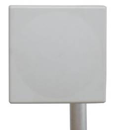
Table 1 Technical specifications
|
Antenna type |
ANT-5018P-M3 |
|
|
Operating frequency range |
5150 MHz to 5850 MHz |
|
|
Bandwidth |
700 MHz |
|
|
Peak gain |
18 dBi |
|
|
Front and Back Ratio |
≥ 30 dB |
|
|
Horizontal beamwidth |
17 degrees |
|
|
Vertical beamwidth |
17 degrees |
|
|
Voltage standing wave ratio (VSWR) |
≤ 1.8 |
|
|
Impedance |
50 Ω |
|
|
Polarization type |
Vertical |
Horizontal |
|
Max. power |
20 W |
|
|
Connector |
N-Female |
|
|
Dimensions |
261 × 261 × 35 mm (10.28 × 10.28 × 1.38 in) |
|
|
Weight |
1.15 kg (2.54 lb) |
|
|
Operating temperature |
–40°C to +60°C (–40°F to +140°F) |
|
|
Mast diameter |
40 to 65 mm (1.57 to 2.56 in) |
|
|
Installation |
Mast mounting |
|
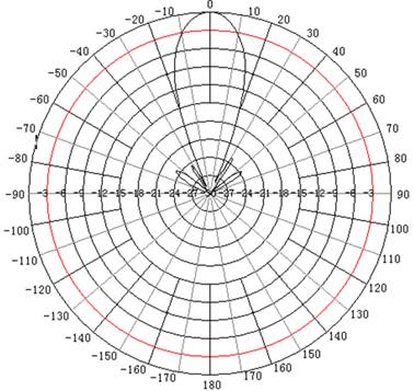
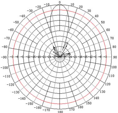
Figure 2 and Figure 3 show the horizontal and vertical radiation patterns.
Safety precautions
|
|
WARNING! · Installing antennas is dangerous. For your safety, follow the installation directions. · Keep the antenna away from power source, street lamps, distribution box, or other places that may cause power shock. · Do not touch any power lines for your safety. |
· Keep safety in mind when you select your installation site. Keep the antenna away from electric power lines and other lines.
· Do not work alone when you install the antenna.
· If you need to raise the mast, work with other people to avoid bodily injury.
· Do not use a metal ladder. Do not work on a wet or windy day. Dress properly, for example, shoes with rubber soles. Wear rubber gloves.
· If the antenna, antenna cable, or any other installation accessory drops, get away from it to avoid bodily injury.
· If an accident, for example, electrical shock, occurs with the power lines, immediately call for qualified emergency help.
Installation guidelines
To ensure the best possible performance of the antenna, follow these guidelines:
· Install the antenna vertically and make sure the antenna bottom is facing downwards.
· Keep the antenna away from metal obstructions such as heating and air-conditioning ducts.
· The density of the wall materials determines the number of walls signals can pass through and still ensure data communication. Consider the following before choosing the location to install the antenna:
? Signals can penetrate vinyl and paper walls with little affect to signal strength.
? Signals can penetrate one or two solid or pre-cast concrete walls with signal strength not degraded.
? Signals can penetrate three or four concrete walls with signal strength not degraded.
? Signals can penetrate five or six wood walls with signal strength not degraded.
? Signals cannot penetrate a metal wall even if the metal covering is very thin.
? Signals cannot penetrate a wire mesh spaced between 2 and 3 cm (0.79 and 1.18 in).
· Keep the antenna away from microwave ovens and 2-GHz wireless phones, because they operate in the same frequency range as the device to which your antenna is connected and can cause signal interference.
Choosing a mounting location
To achieve best possible performance, install the antenna as high as possible, such as building top, mountain top, and tower top. In addition, mount the antenna clear of any metal obstructions to the sides of the radiating element, and use a cable as short as possible to connect the antenna and AP.
Mounting the antenna
You install the ANT-5018P-M3 antenna on a mast. Installation accessories for mounting the antenna on a mast are provided (installation tools are user provided). If you intend to install your antenna on another surface, you must provide the appropriate installation accessories.
Tools and accessories required
· One mounting kit provided with the antenna:
? One L-mounting bracket
? Two mast-mount clamps
? Two U-bolts with four sets of M6 nuts, spring washers, and flat washers
? Four M4 × 8 screws
? Four M4 flat washers
? Four M4 spring washers
· User-supplied tools:
? One adjustable wrench
? One mast with a diameter of 40 to 65 mm (1.57 to 2.56 in)
Mounting the antenna on a mast
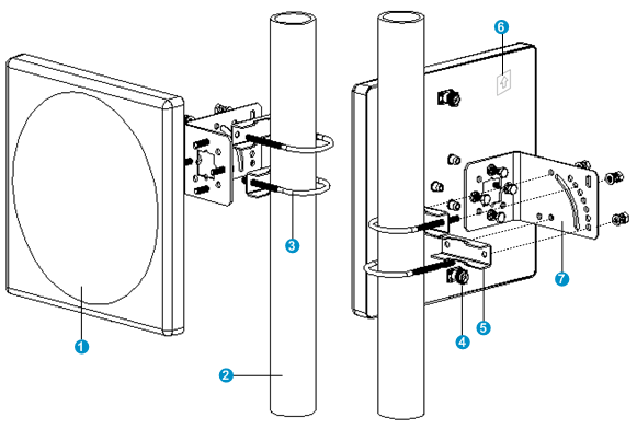
1. Thread a cable through the hole in the middle of the L-mounting bracket (callout 7 in Figure 4), connect it to the connector (callout 4 in Figure 4) on the antenna, and use a waterproof tape to weatherproof the connection.
2. Use four M4 × 8 screws, four flat washers, and four spring washers to attach the L-mounting bracket to the antenna.
3. Place a U-bolt around the mast, and pass the U-bolt through the target installation holes on a mast-mount clamp.
4. Place a spring washer and flat washer on each end of the U-bolt, start an M6 nut on each end of the U-bolt, and tighten the nuts with an adjustable wrench.
5. Repeat steps 3 and 4 to attach the other U-bolt to the other mast-mount clamp.
6. Make sure the polarization arrow (callout 6 in Figure 4) of the antenna is pointing up.
7. To change the vertical orientation of the antenna, select different installation holes in the L-mounting bracket as needed. To change the horizontal orientation of the antenna, turn the U-bolts around the mast.
8. Fasten all screws and nuts.
Figure 4 Mounting the antenna on a mast
|
(1) Antenna |
(2) Mast |
(3) U-bolt |
|
(4) Connector |
(5) Mast-mount clamp |
(6) Polarization arrow |
|
(7) L-mounting bracket |
||
Figure 5 Top view of the mounting kit
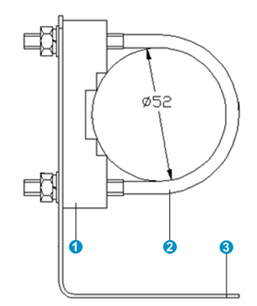
|
(1) Mast-mount clamp |
(2) U-bolt |
(3) L-mounting bracket |
Recommended cable
H3C recommends that you use a high-quality, low-loss cable with the antenna. Coaxial cable loses efficiency as the frequency increases, causing signal loss. Keep the cable as short as possible because cable length also causes signal loss (the longer the run, the greater the loss).
