| Title | Size | Downloads |
|---|---|---|
| H3C ANT-5016P-M2 Patch Antenna Installation Guide-5W100-book.pdf | 197.5 KB |
- Table of Contents
- Related Documents
-
- H3C ANT-2015P patch antenna installation guide-5PW100
- H3C ANT-2011P patch antenna installation guide-5PW100
- H3C ANT-2009Y Yagi antenna installation guide-5PW100
- H3C ANT-2005W antenna installtion guide-5PW100
- H3C ANT-2003CM antenna installation guide-5PW100
- H3C ANT-2513P-M2 Patch Antenna Installation Guide-5W100
Technical specifications
The ANT-5016P-M2 antenna is designed for use with H3C outdoor APs that provide 5 GHz antenna ports. Use cables with an N-type connector to connect the antenna to an AP.
Figure 1 Antenna view
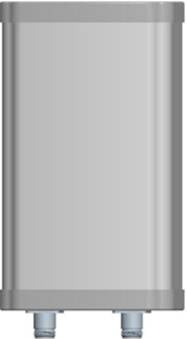
Table 1 Technical specifications
|
Item |
Specification |
|
Operating frequency range |
5150 MHz to 5850 MHz |
|
Peak gain |
15.5 dBi |
|
Front and back ratio |
≥ 25 dB |
|
Horizontal beamwidth |
45 degrees |
|
Vertical beamwidth |
15 degrees |
|
Voltage standing wave ratio (VSWR) |
≤ 2 |
|
Isolation |
≥ 25 dB |
|
Impedance |
50 Ω |
|
Polarization |
±45° |
|
Max. Power |
50 W |
|
Connector |
N-Female |
|
Dimensions |
230 × 128 × 56 mm (9.06 × 5.04 × 2.20 in) |
|
Weight |
1.2 kg (2.65 lb) |
|
Operating temperature |
–40°C to +60°C (–40°F to +140°F) |
|
Mast diameter |
35 to 75 mm (1.38 to 2.95 in) |
|
Installation method |
Mast mounting |
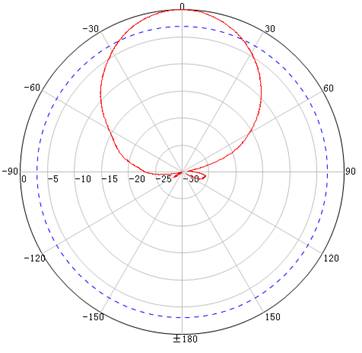
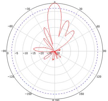
Figure 2 and Figure 3 show the horizontal and vertical radiation patterns of the antenna.
Safety precautions
|
|
WARNING! · To avoid electric shock, locate the antenna away from power sources, street lamps, or distribution boxes. · To avoid serious injury, do not touch any power lines. |
For your safety, follow these safety instructions to install an antenna:
· To avoid bodily injury caused by electric shock or tangled wires, locate the antenna away from electric power lines and other lines.
· Do not work alone when you install the antenna. Determine the installation location and procedure with other installation personnel.
· If you need to raise a mast, work with other people to avoid bodily injury.
· Do not use a metal ladder.
· Do not work on a wet, windy, rainy, or lightning day.
· Dress as required for antenna installation. Wear rubber gloves and shoes with rubber soles.
· If the antenna, antenna cable, or any other installation accessory drops, get away from it to avoid bodily injury.
· If an accident, such as electrical shock, occurs, call for emergency help immediately.
Installation guidelines
For optimal performance of the antenna, follow these installation guidelines:
· Make sure the antenna bottom faces downwards.
· Make sure the antenna is clear of metal obstructions such as heating and air-conditioning ducts.
· 5 GHz signals are heavily attenuated when they are passing through solid walls. Mount the antenna clear of solid walls to the signal sides.
Choosing a mounting location
Follow these guidelines to choose a mounting location for the antenna:
· For the best performance, mount the antenna to a position as high as possible, such as top of a building, mountain, or tower. The higher an antenna, the better it performs.
· Keep the antenna clear of metal obstructions.
Mounting the antenna
You can install the antenna on a 35 to 75 mm (1.38 to 2.95 in) mast. The antenna is provided with a mast-mount bracket. Prepare an adjustable wrench yourself.
For other installation methods, you need to prepare installation accessories yourself.
Mounting the antenna on a mast
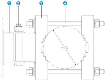
1. As shown in Figure 4, remove the right-side clamp from the mast-mount bracket. Attach the bracket to the mast and reinstall the right-side clamp.
2. Orient the antenna as required.
3. To change the orientation of the antenna, use either of the following methods:
? For elevation adjustment, loosen the nuts on the arm fixing bolt and turn the swing arm on the arm fixing bolt. Reinstall the nuts after the adjustment.
? For azimuth adjustment, loosen the nuts on the mast-mount bolts and turn the antenna bracket around the mast. Reinstall the nuts after the adjustment.
4. Connect the cables and weatherproof the connection points.
Figure 4 Top view of the mast-mount installation kit
|
(1) Swing arm |
(2) Arm-fixing bolt |
|
(3) Clamp |
(4) Mast-mount bolt |
Figure 5 Mounting the antenna on a mast
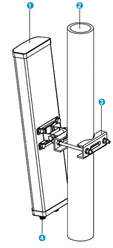
|
(1) Antenna |
(2) Mast |
|
(3) Mast-mount bracket |
(4) Antenna port |
Antenna cable
As a best practice, use high-quality, low-loss antenna cables. Coaxial cable loses efficiency as the frequency increases. This causes signal loss. Cable length also affects cable efficiency. The longer the cable, the greater the loss. Make sure the cable is as short as possible.
