| Title | Size | Downloads |
|---|---|---|
| H3C ANT-2513P-M2 Patch Antenna Installation Guide-5W100-book.pdf | 258.32 KB |
- Table of Contents
- Related Documents
-
- H3C ANT-2015P patch antenna installation guide-5PW100
- H3C ANT-2011P patch antenna installation guide-5PW100
- H3C ANT-2009Y Yagi antenna installation guide-5PW100
- H3C ANT-2005W antenna installtion guide-5PW100
- H3C ANT-2003CM antenna installation guide-5PW100
- H3C ANT-5016P-M2 Patch Antenna Installation Guide-5W100
Contents
H3C ANT-2513P-M2 patch antenna installation guide
Installation accessories and tools
Mounting the antenna on a mast
Technical specifications
The ANT-2513P-M2 dual-band 2x2 MIMO antenna is small in size and has lower horizontal and vertical beamwidths. It is designed for use on rail vehicles.
Use two cables with an N-type connector to connect the antenna to an AP.
Figure 1 Antenna view

Table 1 Technical specifications
|
Item |
Specification |
|
|
Operating frequency range |
2400 MHz to 2500 MHz |
5150 MHz to 5850 MHz |
|
Peak gain |
13 dBi |
13 dBi |
|
Front and back ratio |
≥ 25 dB |
≥ 25 dB |
|
Horizontal beamwidth |
30 degrees |
|
|
Vertical beamwidth |
30 degrees |
|
|
Voltage standing wave ratio (VSWR) |
≤ 1.5 |
≤ 2.0 |
|
Impedance |
50 Ω |
|
|
Polarization |
1 x vertical and 1 x horizontal |
|
|
Max. Power |
50 W |
|
|
Connector |
N-Female |
|
|
Dimensions |
260 × 190 × 30 mm (10.24 × 7.48 × 1.18 in) |
|
|
Weight |
0.85 kg (1.87 lb) |
|
|
Operating temperature |
–40°C to +70°C (–40°F to +158°F) |
|
|
Mast diameter |
30 to 50 mm (1.18 to 1.97 in) |
|
|
Installation method |
Mast mounting |
|
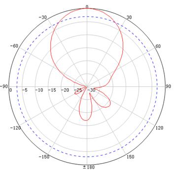
Figure 2, Figure 3, Figure 4, and Figure 5 show the horizontal and vertical radiation patterns.
Figure 2 2.4 GHz horizontal pattern
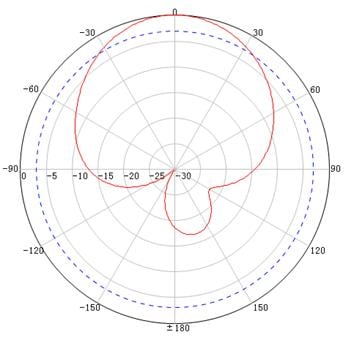
Figure 3 5 GHz horizontal pattern
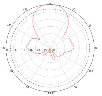
Figure 4 2.4 GHz vertical pattern
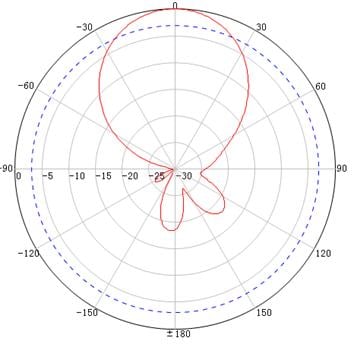
Figure 5 5 GHz vertical pattern
Safety precautions
|
|
WARNING! · To avoid electric shock, locate the antenna away from power sources, street lamps, or distribution boxes. · To avoid serious injury, do not touch any power lines. |
For your safety, follow these safety instructions to install an antenna:
· To avoid bodily injury caused by electric shock or tangled wires, locate the antenna away from electric power lines and other lines.
· Do not work alone when you install the antenna. Determine the installation location and procedure with other installation personnel.
· If you need to raise a mast, work with other people to avoid bodily injury.
· Do not use a metal ladder.
· Do not work on a wet, windy, rainy, or lightning day.
· Dress as required for antenna installation. Wear rubber gloves and shoes with rubber soles.
· If the antenna, antenna cable, or any other installation accessory drops, get away from it to avoid bodily injury.
· If an accident, such as electrical shock, occurs, call for emergency help immediately.
Installation guidelines
For optimal performance of the antenna, follow these installation guidelines:
· Make sure the antenna is clear of metal obstructions such as heating and air-conditioning ducts.
· The materials and density of walls determine the number of walls signals can pass through. Consider the following before choosing the location to install the antenna:
? Signals can penetrate vinyl and paper walls with little affect to strength.
? Signals can penetrate one or two solid or pre-cast concrete walls with strength not degraded.
? Signals can penetrate three or four concrete walls with strength not degraded.
? Signals can penetrate five or six wood walls with strength not degraded.
? Signals cannot penetrate a metal wall even if the metal covering is very thin.
? Signals cannot penetrate a wire mesh spaced between 2 and 3 cm (0.79 and 1.18 in).
· Keep the antenna away from microwave ovens and 2.4-GHz wireless phones. These devices operate in the same frequency range as the AP and antenna and can cause signal interference.
Mounting the antenna
You can install the antenna on a mast. The antenna is provided with mast-mounting installation accessories. Prepare installation tools yourself.
For other installation methods, you need to prepare installation accessories yourself.
Installation accessories and tools
The antenna is provided with the following mast-mounting installation accessories:
· One L-mounting bracket.
· One mast-mount clamp.
· Two U-bolt kits. Each kit contains one U-bolt, two M6 nuts, two M6 spring washers, and two M6 flat washers.
· Four M6 x 8 nuts.
· Four M6 flat washers.
· Four M6 spring washers.
Prepare the following installation tools:
· One 30 to 50 mm (1.18 to 1.97 in) diameter mast.
· One adjustable wrench.
Mounting the antenna on a mast
1. Connect the antenna cables to the antenna ports. Weatherproof the connection points.
2. Use four M6 nuts, four M6 flat washers, and four M6 spring washers to attach the L-mounting bracket to the antenna.
3. Place the mast-mount clamp against the L-mounting bracket and align the installation holes. Place the U-bolt around the mast, and pass the U-bolt through the installation holes in the mast-mount clamp.
4. Attach a flat washer, a spring washer, and an M6 hex nut in sequence on each end of the U-bolt. Fasten the M6 hex nuts.
5. Make sure the polarization arrow on the antenna points up.
6. To change the orientation of the antenna, use either of the following methods:
? For elevation adjustment, adjust the mast-mount clamp position by using different installation holes in the L-mounting bracket.
? For azimuth adjustment, loosen the nuts on the U-bolt and rotate the U-bolt around the mast. Reinstall the nuts after the adjustment.
Figure 6 Mounting the antenna on a mast
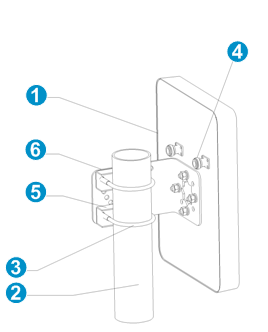
|
(1) Antenna |
(2) Mast |
(3) U-bolt |
|
(4) Antenna port |
(5) Mast-mount clamp |
(6) L-mounting bracket |
Figure 7 Top view of mast mounting
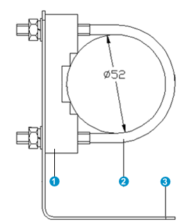
|
(1) Mast-mount clamp |
(2) U-bolt |
(3) L-mounting bracket |
Antenna cable
As a best practice, use a high-quality, low-loss antenna cable. Coaxial cable loses efficiency as the frequency increases. This causes signal loss. Cable length also affects cable efficiency. The longer the cable, the greater the loss. Make sure the cable is as short as possible.
