- Table of Contents
- Related Documents
-
| Title | Size | Download |
|---|---|---|
| 01-Text | 3.51 MB |
General safety recommendations
Examining the installation site
Confirming installation preparations
Mounting the device on a workbench
Installing the device in a 19-inch rack
Mounting brackets and slide rails
Rack-mounting the device by using front and rear mounting brackets and slide rails
Rack mounting the device by using front and rear mounting brackets
Rack-mounting the device by using the front mounting brackets
(Optional) Installing network port lightning protectors
(Optional) Installing a surge protected power strip
Connecting the console cable and setting terminal parameters
Connecting the device to an RPS
4 Hardware management and maintenance
Displaying hardware information for the device
Displaying software and hardware version information for the device
Displaying operational statistics for the device
Displaying detailed information about the device
Displaying the electronic label data for the device
Displaying the CPU usage of the device
Displaying the memory usage of the device
Displaying the operating state of the built-in fans
Displaying the operating state of power modules
5 Appendix A Chassis views and technical specifications
Transceiver module, fiber connector, and optical fiber views
Transceiver module specifications
1 Preparing for installation
H3C WX3000H Series Access Controllers include the following models:
· WX3010H.
· WX3010H-X-PWR.
· WX3010H-L-PWR.
· WX3024H.
· WX3024H-L-PWR.
Safety recommendations
General safety recommendations
To avoid any equipment damage or bodily injury, read the following safety recommendations before installation. Note that the recommendations do not cover every possible hazardous condition.
· Make sure the installation site is flat, vibration-free, and away from electromagnetic interferences. ESD-prevention and anti-slip measures are in place.
· Do not place the device on an unstable case or desk. The device might be severely damaged in case of a fall.
· Keep the chassis and installation tools away from walk areas.
· Keep the chassis clean and dust-free.
· Do not place the device near water or in a damp environment. Prevent water or moisture from entering the device chassis.
· Ensure good ventilation of the equipment room and keep the air inlet and outlet vents of the device free of obstruction.
· Make sure the operating voltage is in the required range.
· Use a screwdriver to fasten screws.
· After you move the device from a location below 0°C (32°F) to the equipment room, follow these guidelines to prevent condensation:
¡ Wait a minimum of 30 minutes before unpacking the device.
¡ Wait a minimum of 2 hours before powering on the device.
Electrical safety
· Carefully examine your work area for possible hazards, such as moist floors, ungrounded power extension cables, or missing safety grounds.
· Locate the emergency power-off switch in the room before installation. Shut off the power immediately if an accident occurs.
· Remove all the external cables (including power cords) before moving the chassis.
· Do not work alone when you operate the device with the device powered on.
· Always verify that the power has been disconnected when you perform operations that require the device to be powered off.
Laser safety
|
|
WARNING! · Do not stare into any open apertures of operating transceiver modules or optical fiber connectors. The laser light emitted from these apertures might hurt your eyes. · Before you remove the optical fiber connector from a fiber port, execute the shutdown command in interface view to shut down the port. |
|
|
CAUTION: Insert a dust cap into any open optical fiber connector and a dust plug into any open fiber port or transceiver module port to protect them from contamination and ESD damage. |
Examining the installation site
The device can only be used indoors. To ensure correct operation and a long lifespan for your device, the installation site must meet the requirements in this section.
Temperature and humidity
Maintain the temperature and humidity in the equipment room at acceptable levels.
· Lasting high relative humidity can cause poor insulation, electricity leakage, mechanical property change of materials, and metal corrosion.
· Lasting low relative humidity can cause washer contraction and ESD and cause problems including loose mounting screws and circuit failure.
· High temperature can accelerate the aging of insulation materials and significantly lower the reliability and lifespan of the device.
To ensure correct operation of the device, the equipment room must meet the temperature and humidity requirements listed in Table1-1.
Table1-1 Temperature/humidity requirements in the equipment room
|
Temperature |
Humidity |
|
0°C to 45°C (32°F to 113°F) |
5% RH to 95% RH, noncondensing |
Cleanliness
Dust buildup on the chassis might result in electrostatic adsorption, which causes poor contact of metal components and contact points, especially when indoor relative humidity is low. In the worst case, electrostatic adsorption can cause communication failure.
Table1-2 Dust concentration limit in the equipment room
|
Substance |
Concentration limit (particles/m3) |
|
Dust particles |
≤ 3 x 10⁴ (no visible dust on the tabletop over three days) |
|
NOTE: Dust particle diameter ≥ 5 µm |
|
To eliminate corrosion and premature aging of components, the equipment room must also meet limits on salts, acids, and sulfides, as shown in Table1-3.
Table1-3 Harmful gas limits in an equipment room
|
Gas |
Max. (mg/m3) |
|
SO2 |
0.2 |
|
H2S |
0.006 |
|
NH3 |
0.05 |
|
Cl2 |
0.01 |
|
NO2 |
0.04 |
Cooling
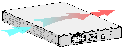
The device uses left to right airflow for heat dissipation. Plan the installation site for adequate ventilation.
· Leave a minimum clearance of 100 mm (3.94 in) around the air vents.
· Make sure the rack or workbench has a good ventilation system.
Figure1-1 Airflow through the chassis (WX3010H-X-PWR)
ESD prevention
To prevent electrostatic discharge (ESD), follow these guidelines:
· Ground the device and rack or workbench reliably.
· Take dust-proof measures for the equipment room. For more information, see "Cleanliness."
· Maintain the humidity and temperature at acceptable levels. For more information, see "Temperature and humidity."
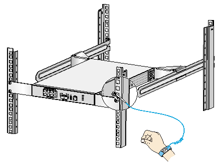
· Before working with the device, wear an ESD wrist strap or gloves and ESD garment, and remove conductive objects such as jewelry or watch. Make sure the wrist strap makes good skin contact and is reliably grounded.
· Always remember to wear an ESD wrist strap before working with a transceiver module.
No ESD wrist strap is provided with the device. Prepare one yourself.
To attach an ESD wrist strap:
1. Wear the wrist strap on your wrist.
2. Lock the wrist strap tight around your wrist to maintain good contact with the skin.
3. Secure the wrist strap lock and the alligator clip lock together.
4. Attach the alligator clip to the rack.
5. Make sure the rack is reliably grounded.
Figure1-2 Attaching an ESD wrist strap (WX3010H-X-PWR)
EMI
All electromagnetic interference (EMI) sources, from outside or inside of the device and application system, adversely affect the device in the following ways:
· A conduction pattern of capacitance coupling.
· Inductance coupling.
· Electromagnetic wave radiation.
· Common impedance (including the grounding system) coupling.
To prevent EMI, use the following guidelines:
· If AC power is used, use a single-phase three-wire power receptacle with protection earth (PE) to filter interference from the power grid.
· Keep the device far away from radio transmitting stations, radar stations, and high-frequency devices.
· Use electromagnetic shielding, for example, shielded interface cables, when necessary.
· To prevent signal ports from getting damaged by overvoltage or overcurrent caused by lightning strikes, route interface cables only indoors.
Lightning protection
To better protect the device from lightning, follow these guidelines:
· Make sure the grounding cable of the chassis is reliably grounded.
· Make sure the grounding terminal of the AC power receptacle is reliably grounded.
· Install a lightning protector at the input end of the power module to enhance the lightning protection capability of the power module.
Installation accessories
The installation accessories vary by device model. Table1-4 and Table1-5 describe the installation accessories available for the access controllers.
Table1-4 Installation accessories for the access controllers (1)
|
Accessory |
WX3010H |
WX3010H-X-PWR |
WX3010H-L-PWR |
|
|
Cage nut |
|
4, user supplied |
8, user supplied |
4, user supplied |
|
M6 rack screw |
|
4, user supplied |
8, user supplied |
4 |
|
M4 mounting bracket screw |
|
8 |
16 |
4 |
|
M3 mounting bracket screw |
|
N/A |
N/A |
N/A |
|
M4 shoulder screw for weight bearing |
|
N/A |
N/A |
N/A |
|
Rubber feet |
|
1 set |
1 set |
1 set |
|
Grounding cable |
|
1 |
1 |
1 |
|
Console cable |
|
1 |
1 |
1 |
|
AC power cord |
|
1 |
1 |
1 |
|
Bail latch |
|
1 |
1 |
1 |
|
Front mounting bracket |
|
|
|
|
|
Rear mounting bracket |
N/A |
|
N/A |
|
|
Slide rail |
N/A |
|
N/A |
|


Table1-5 Installation accessories for the access controllers (2)
|
Accessory |
WX3024H |
WX3024H-L-PWR |
|
|
Cage but |
|
8, user supplied |
4, user supplied |
|
M6 rack screw |
|
8, user supplied |
4 |
|
M4 mounting bracket screw |
|
4 |
N/A |
|
M3 mounting bracket screw |
|
N/A |
8 |
|
M4 shoulder screw for weight bearing |
|
2 |
N/A |
|
Rubber feet |
|
1 set |
1 set |
|
Grounding cable |
|
1 |
1 |
|
Console cable |
|
1 |
1 |
|
AC power cord |
|
1 |
1 |
|
Bail latch |
|
1 |
1 |
|
Front mounting bracket |
|
|
|
|
Rear mounting bracket |
|
N/A |
|
|
Slide rail |
N/A |
N/A |
|

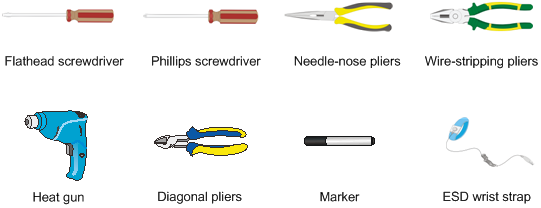
Installation tools
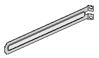
The following installation tools are for illustration only. Prepare installation tools as required.
Pre-installation checklist
Table1-6 Pre-installation checklist
|
Item |
Requirements |
Result |
|
|
Installation site |
Ventilation |
· There is a minimum clearance of 100 mm (3.94 in) around the inlet and outlet vents for heat dissipation of the device chassis. · A good ventilation system is available at the installation site. |
|
|
Temperature |
0°C to 45°C (32°F to 113°F) |
|
|
|
Humidity |
5% RH to 95% RH (noncondensing) |
|
|
|
Cleanliness |
· Dust concentration ≤ 3 × 10⁴ particles/m3 · No dust on desk within three days |
|
|
|
ESD prevention |
· The equipment and rack or workbench are reliably grounded. · The equipment room is dust-proof. · The humidity and temperature are at acceptable levels. · An ESD wrist strap is available. |
|
|
|
EMI prevention |
· Effective measures are taken for filtering interference from the power grid. · The protection ground of the device is away from the grounding facility of power equipment or lightning protection grounding facility. · The device is far away from radio transmitting stations, radar stations, and high-frequency devices. · Electromagnetic shielding, for example, shielded interface cables, is used as required. |
|
|
|
Lightning protection |
· The device is reliably grounded. · The AC power source is reliably grounded. · (Optional.) Network port lightning protectors are available. · (Optional.) A surge protected power strip is available. |
|
|
|
Electricity safety |
· A UPS is available. · The power-off switch in the equipment room is identified and accessible so that the power can be immediately shut off when an accident occurs. |
|
|
|
Rack-mounting requirements |
· The rack has a good ventilation system. · The rack is sturdy enough to support the weight of the device and installation accessories. · The size of the rack is appropriate for the device. · The front and rear of the rack are a minimum of 0.8 m (31.50 in) away from walls or other devices. |
|
|
|
Safety precautions |
· The device is far away from any moist area and heat source. · You have located the emergency power switch in the equipment room. |
|
|
|
Accessories |
Accessories provided with the device are available. |
|
|
|
Reference |
· Documents shipped with the device are available. · Online documents are available. |
|
|
2 Installing the device
|
|
WARNING! Keep the tamper-proof seal on a mounting screw on the chassis cover intact, and if you want to open the chassis, contact H3C Support for permission. Otherwise, H3C will not be liable for any consequence caused thereby. |
Confirming installation preparations
Before you install the device, verify that you have read "Preparing for installation" carefully and the installation site meets all the requirements.
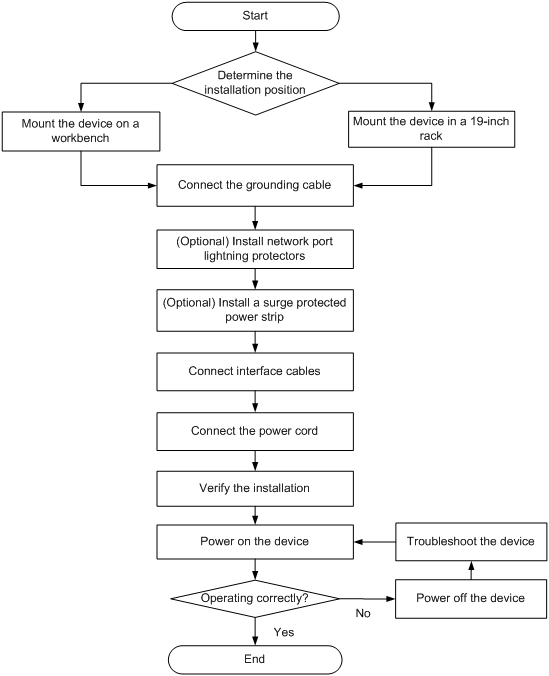
Installation flow
Mounting the device on a workbench
|
|
CAUTION: Do not place heavy objects on the device. |
If a standard 19-inch rack is not available, you can mount the device on a clean, flat workbench.
To mount the device on a workbench:
1. Place the device upside down. Clean the recessed areas in the chassis bottom.
2. Attach the four rubber feet to the recessed areas in the chassis bottom.
3. Place the device on the workbench with the upside up. Make sure the four rubber feet stand firmly on the workbench.
Figure2-2 Mounting the device on a workbench (WX3010H-X-PWR)
Installing the device in a 19-inch rack
Installation methods
Table2-1 Installation methods for the access controllers
|
Device model |
Installation method |
||
|
Using front and rear mounting brackets and slide rails |
Using front and rear mounting brackets |
Using front mounting brackets |
|
|
WX3010H |
× |
× |
√ |
|
WX3010H-X-PWR |
√ |
× |
× |
|
WX3010H-L-PWR |
× |
× |
√ |
|
WX3024H |
× |
√ |
× |
|
WX3024H-L-PWR |
× |
× |
√ |
Mounting brackets and slide rails
The available mounting brackets and slide rails vary by device model. Table2-2 describes the mounting brackets and slide rails available for the access controllers.
Table2-2 Mounting brackets and slide rails available for the access controllers
|
Device model |
Front mounting bracket |
Rear mounting bracket |
Slide rail |
|
WX3010H |
|
N/A |
N/A |
|
WX3010H-X-PWR |
|
|
|
|
WX3010H-L-PWR |
|
N/A |
N/A |
|
WX3024H |
|
|
N/A |
|
WX3024H-L-PWR |
|
N/A |
N/A |


Installing cage nuts
Before mounting the device in a rack, install cage nuts on the rack.
To install cage nuts:
1. Wear an ESD wrist strap and make sure the rack is stable and is reliably grounded.
2. Use a mounting bracket to mark the cage nut installation positions on the rack posts.
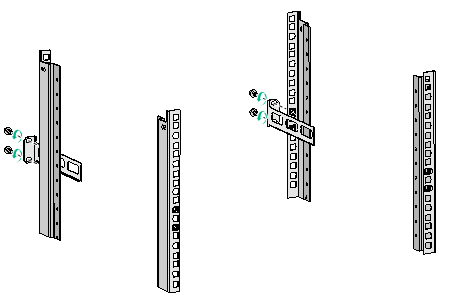
3. Install cage nuts at the marked positions.
Figure2-3 Installing cage nuts
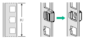
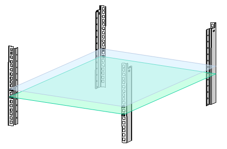
For a device that uses rear mounting brackets or slide rails for installation, install two cage nuts on each rack posts, keeping 1U distance between the two cage nuts. Make sure the upper cage nuts on the four rack posts are on the same horizontal plane and the lower cage nuts are on the same horizontal plane.
Figure2-4 Cage nuts on the same horizontal planes
Rack-mounting the device by using front and rear mounting brackets and slide rails
A WX3010H-X-PWR access controller uses front and rear mounting brackets and slide rails for rack mounting.
To rack-mount the device by using front and rear mounting brackets and slide rails:
1. Install cage nuts on the rack posts. See "Installing cage nuts."
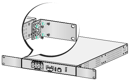
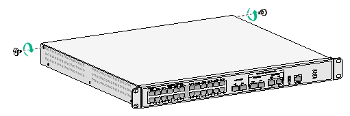
2. Use M4 screws supplied with the front mounting brackets to attach the front mounting brackets to the device.
Figure2-5 Attaching the front mounting brackets to the device
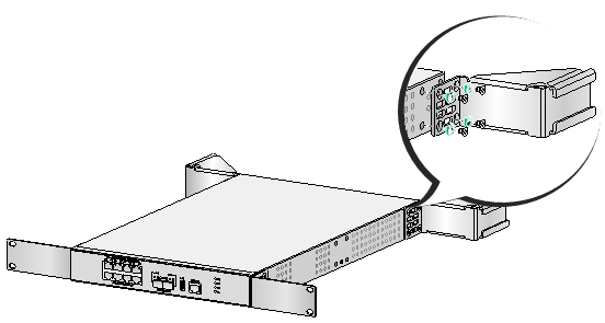
3. Use M4 screws supplied with the rear mounting brackets to attach the rear mounting brackets to the device.
Figure2-6 Attaching the rear mounting brackets to the device
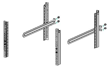
4. Use M6 rack screws and cage nuts to attach the slide rails to the rear rack posts.
Figure2-7 Attaching the slide rails to the rear rack posts
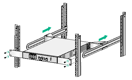
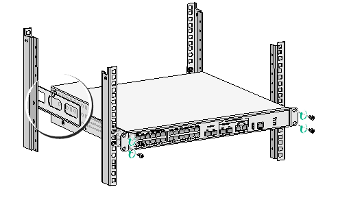
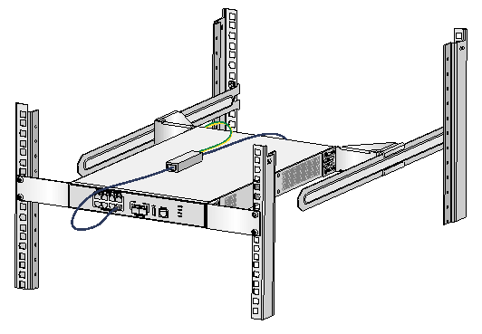
5. Align the rear mounting brackets with the slide rails, slide the rear mounting brackets onto the slide rails, and push the device into the rack along the slide rails. Use M6 rack screws and cage nuts to secure the front mounting brackets to the front rack posts, as shown in Figure2-8. Make sure the device is installed securely in the rack.
Figure2-8 Installing the device in the rack by using front and rear mounting brackets and slide rails
Rack mounting the device by using front and rear mounting brackets
A WX3024H access controller uses front and rear mounting brackets for rack mounting.
To rack-mount the device by using front and rear mounting brackets:
1. Install cage nuts on the rack posts. See "Installing cage nuts."
2. Use M4 screws supplied with the front mounting brackets to attach the front mounting brackets to the device.
Figure2-9 Attaching the front mounting brackets to the device

3. Attach the M4 shoulder screws supplied with the rear mounting brackets to the device. The M4 shoulder screws are used for weight bearing. See Figure2-10 for the installation position.
Figure2-10 Attaching M4 shoulder screws to the device
4. Use M6 rack screws and cage nuts to attach the slide rails to the rear rack posts.
Figure2-11 Attaching the slide rails to the rear rack posts
5. Push the device into the rack. Make sure the shoulder screws rest firmly on the upper edge of the slide rails so that the weight of the device can rest on the shoulder screws. Use M6 rack screws and cage nuts to secure the front mounting brackets to the front rack posts. Make sure the device is installed securely in the rack.
Figure2-12 Installing the device in the rack by using front and rear mounting brackets
Rack-mounting the device by using the front mounting brackets
The WX3010H, WX3010H-L-PWR, and WX3024H-L-PWR access controllers use front mounting brackets for rack mounting.
To attach front mounting brackets to a WX3010H access controller, see "Rack-mounting the device by using front and rear mounting brackets and slide rails."
To attach front mounting brackets to a WX3010H-L-PWR or WX3024H-L-PWR access controller, see "Rack mounting the device by using front and rear mounting brackets."
The following procedure uses the WX3010H as an example.
To rack-mount the device by using the front mounting brackets:
1. Install cage nuts on the rack posts. See "Installing cage nuts."
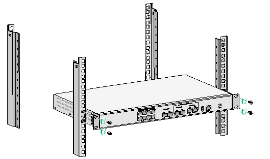
2. Attach the front mounting bracket to the device.
3. Put the device in the rack. Use M6 rack screws and cage nuts to secure the front mounting brackets to the front rack posts, as shown in Figure2-13. Make sure the device is installed securely in the rack.
Figure2-13 Installing the device in the rack by using front mounting brackets (WX3010H)
Grounding the device
|
|
WARNING! · Correctly connecting the grounding cable is crucial to lightning protection and EMI protection. Before you install and use the device, make sure the device is reliably grounded. · Connect the grounding cable to the grounding system in the equipment room. Do not connect it to a fire main or lightning rod. |
The following procedure uses the WX3010H-X-PWR access controller as an example.
To ground the device:
1. Use a Phillips screwdriver to remove the grounding screw from the chassis.
2. Use the grounding screw to attach one end (with ring terminal) of the grounding cable to the chassis.
3. Connect the other end of the grounding cable according to the grounding method you use:
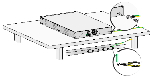
¡ Ground the device with a grounding strip—If a grounding strip is available at the installation site, connect the other end of the grounding cable to the grounding strip and make sure the grounding strip has been reliably grounded.
Figure2-14 Grounding the device with a grounding strip
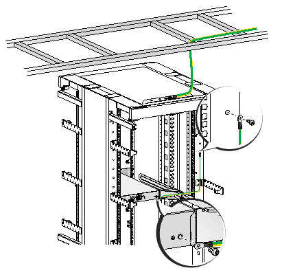
¡ Ground the device with the rack—Connect the other end of the grounding cable to the grounding point on the rack and make sure the rack has been reliably grounded.
Figure2-15 Grounding the device with the rack
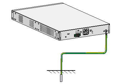
¡ Grounding the device with a grounding conductor buried in the earth—If earth is available at the installation site, hammer a 0.5 m (1.64 ft) or longer angle iron or steel tube into the earth to serve as a grounding conductor. Weld the yellow-green grounding cable to the angel iron or steel tube and treat the joint for corrosion protection.
Figure2-16 Grounding the device by burying the grounding conductor into the earth
(Optional) Installing network port lightning protectors
|
|
IMPORTANT: · Before installing a network port lightning protector, read the instructions in the document that comes with the protector. · Network port lightning protectors are available only for 10M/100M/1000M RJ-45 Ethernet copper ports. · If multiple network ports have network cables routed outdoors, install a network port lightning protector for each network port. |
If part of the network cable for a network port is routed outdoors, install a network port lightning protector for the port to protect against damages caused by lightning strikes.
No network port lightning protectors are provided with the device. Purchase them yourself as required.
To install a network port lightning protector for a network port:
1. Use a double-faced adhesive tape to stick the network port lightning protector onto the device chassis, and make sure it is as close to the grounding screw of the device as possible.
2. Cut the ground wire of the protector to a length (as short as possible) as required by the distance between the protector and the grounding screw of the device. Attach the ground wire securely to the grounding screw of the device.
Make sure the grounding screw of the device is reliably grounded.
3. Use a multimeter to verify that the ground wire of the protector makes good contact with the grounding screw of the chassis.
4. Insert the outdoor network cable into the protector's Surge end marked IN, and insert the cable from the network port into the Protect end marked OUT.
5. Examine the port LED to verify that the port is operating correctly.
Figure2-17 Installing a lightning protector for a network port (WX3010H-X-PWR)
(Optional) Installing a surge protected power strip
|
|
IMPORTANT: Before installing a surge protected power strip, read the instructions in the document that comes with the strip. |
If you use an AC power line routed from outdoors for the device, use a surge protected power strip for the device to protect against damages caused by lightning strikes. No surge protected power strip is provided with the device. Purchase one yourself if required.
To use a surge protected power strip, first connect the AC power line routed from outdoors to the strip and then connect the power cord from the device to the strip.
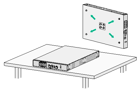
You can attach the surge protected power strip to the rack, workbench, or wall of the equipment room.
Connecting interface cables
Connecting the console cable and setting terminal parameters
To configure and manage the device through the console port, you must run a terminal emulator program, TeraTermPro or PuTTY, on your configuration terminal. You can use the emulator program to connect a network device, a Telnet site, or an SSH site. For more information about the terminal emulator programs, see the user guides for these programs
The following are the required terminal settings:
· Bits per second—9600.
· Data bits—8.
· Stop bits—1.
· Parity—None.
· Flow control—None.
Connecting Ethernet cables
Connecting a copper Ethernet port
1. Connect one end of the Ethernet cable to the copper Ethernet port of the device, and the other end to the Ethernet port of the peer device.
2. After powering on the device, examine the LEDs of the fixed copper Ethernet port.
For more information about the LED description, see "Appendix B LEDs."
Connecting a fiber port
|
|
WARNING! Do not stare into any open apertures of operating transceiver modules or optical fiber connectors. The laser light emitted from these apertures might hurt your eyes. |
|
|
CAUTION: · To connect a fiber port by using an optical fiber, first install a transceiver module in the port and then connect the optical fiber to the transceiver module. · Insert a dust cap into any open optical fiber connector and a dust plug into any open fiber port or transceiver module port to protect them from contamination and ESD damage. · Never bend an optical fiber excessively. The bend radius of an optical fiber must be not less than 10 cm (3.94 in). · Keep the fiber end clean. · Make sure the Tx and Rx ports on a transceiver module are connected to the Rx and Tx ports on the peer end, respectively. |
No transceiver modules are provided with the device. Purchase transceiver modules yourself as required. For transceiver module specifications, see "Appendix A Chassis views and technical specifications."
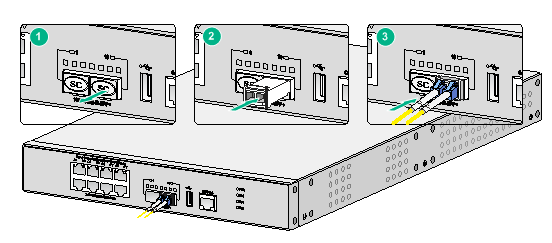
The fiber ports on the device support only LC connectors.
To connect an optical fiber for a fiber port:
1. Remove the dust plug from the fiber port.
2. Pivot the bail latch of the transceiver module up so that it catches a knob on the top of the transceiver module.
3. Holding both sides of the transceiver module, insert the transceiver module slowly into the port.
4. Identify the Rx and Tx ports on the transceiver module. Use the optical fiber to connect the Rx port and Tx port on the transceiver module to the Tx port and Rx port on the peer end, respectively.
5. Examine the port LEDs:
¡ If the LED is on, a fiber link has been set up.
¡ If the LED is off, the link has not been set up. The reason might be wrong connection of the Tx and Rx ends. Swap the fiber connectors in the Tx and Rx ports at one end of the fiber.
Figure2-18 Connecting an optical fiber
Connecting the power cord
|
|
CAUTION: Do not connect both AC and DC power sources to the same device. |
Connecting the AC power cord
|
|
CAUTION: Before connecting the AC power cord, make sure the device is reliably grounded. |
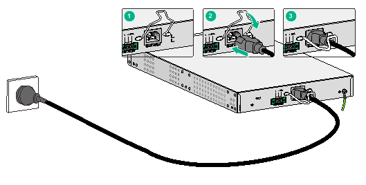
To connect the AC power cord:
1. Pivot the bail latch upward.
2. Connect one end of the AC power cord to the AC-input power receptacle on the device.
3. Pivot the bail latch downward to secure the power cord.
4. Connect the other end of the AC power cord to the AC power source.
Figure2-19 Connecting the device to an AC power source (WX3010H-X-PWR)
Connecting the device to an RPS
Among the RPS power modules, the WX3010H-X-PWR, WX3024H, and WX3024H-L-PWR access controllers support only the RPS 1600-A.
No RPS is provided the device. Prepare one yourself if required.
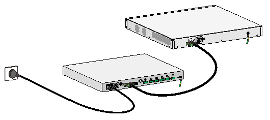
The following procedure uses the WX3010H-X-PWR access controller as an example.
To connect the device to an RPS:
1. Verify that the device is powered off and the RPS is switched off.
2. Use a Phillips screwdriver to remove the screws on the cover on the DC power receptacle and take off the cover.
3. Connect the RPS power cord plug to the DC power receptacle on the chassis.
4. Turn the strain release screws on the RPS power cord plug clockwise so that the RPS power cord plug is firmly seated in the DC power receptacle, and then fasten the strain release screws.
5. Connect the other end of the RPS power cord to an output interface of the RPS.
Figure2-20 Connecting the device to an RPS (WX3010H-X-PWR)
Verifying the installation
Before powering on the device, verify the following information:
· The correct power source is used.
· The grounding cable is securely connected.
· The console cable and power cord are correctly connected.
· If part of the network cable for a port is routed outdoors, verify that a network port lightning protector is used for the port.
· If the power line is routed from outdoors, verify that a surge protected power strip is used for the device.
Starting the device
The following procedure uses the WX3010H-X-PWR access controller as an example.
To start the device:
1. Power on the device. The device initializes its memory and runs the BootWare. The following information appears on the terminal screen:
BootWare Validating...
Press Ctrl+B to access EXTENDED-BOOTWARE MENU...
2. Press Ctrl + B at the prompt within 4 seconds to access the Boot menu. Otherwise, the system enters the system image file reading and self-compressing process.
To access the Boot menu after the system enters the system image file reading and self-compressing process, restart the device.
Loading the main image files...
Loading file cfa0:/system.bin...............................................
............................Done.
Loading file cfa0:/boot.bin.................................................
............................................................................
..............Done.
Image file cfa0:/boot.bin is self-decompressing.............................
...........................Done.
System image is starting...
…
Line con0 is available.
Press ENTER to get started.
3. Press Enter at the prompt, and you can configure the device when the prompt <H3C> appears.
During the startup process, the CPLD is automatically upgraded to the most recent version.
3 Troubleshooting
Power failure
Symptom
The device cannot be powered on and the power status LED PWR/RPS is off. For a device that does not have a power status LED, its system status LED (SYS) is off.
Solution
To resolve the issue:
1. Verify that the power source is as required.
2. Verify that the power cord is connected securely.
3. Verify that the power cord is in good condition.
4. If the issue persists, contact H3C Support.
Software loading failure
Symptom
The device fails in software loading.
Solution
To resolve the issue:
1. Verify that the physical ports are connected securely and correctly.
2. Examine the software loading process displayed on the HyperTerminal for errors. Possible errors include:
¡ Inconsistent baud rates configured for XMODEM and the HyperTerminal.
¡ Incorrect IP address, software name, or TFTP serve path for TFTP.
¡ Incorrect IP address, software name, username, or password for FTP.
3. If the issue persists, contact H3C Support.
4 Hardware management and maintenance
The command lines and outputs depend on the software version that runs on the device. This section uses the WX3010H-X-PWR access controller as an example.
Displaying hardware information for the device
Displaying software and hardware version information for the device
Use the display version command to display software and hardware version information about the device. The output includes the following information:
· The current software.
· The hardware version.
· The device operating time.
The output depends on the software and hardware version of the device.
<H3C> display version
H3C Comware Software, Version 7.1.064, ESS 5118
Copyright (c) 2004-2020 New H3C Techbologies Co., Ltd. All rights reserved.
H3C WX3010H-X uptime is 0 weeks, 0 days, 0 hours, 14 minutes
Last reboot reason : User soft reboot
Boot image: cfa0:/boot.bin
Boot image version: 7.1.064, Release 5324
Compiled Apr 18 2017 16:00:00
System image: cfa0:/system.bin
System image version: 7.1.064, Release 5324
Compiled Apr 18 2017 16:00:00
with 1 1200MHz Multi-core Processor
4064M bytes DDR3
16M bytes NorFlash Memory
4002M bytes CFCard Memory
Hardware Version is Ver.A
CPLD Version is 003
Basic Bootrom Version is 0.06
Extend Bootrom Version is 1.04
[Subslot 0]WX3010H-X Hardware Version is Ver.A
Displaying operational statistics for the device
To display operation statistics of a specific feature module, you must execute the display command for the module.
To display operational statistics of all feature modules at a time, execute the display diagnostic-information command in any view. The command displays the output from the display clock, display version, display device, and display current-configuration commands.
· Save the operational statistics for all feature modules of the device.
<H3C>display diagnostic-information
Save or display diagnostic information (Y=save, N=display)? [Y/N]:y
Please input the file name(*.tar.gz)[cfa0:/ diag.tar.gz]:
Diagnostic information is outputting to cfa0:/ diag.tar.gz.
Please wait...
Save successfully.
To view the contents of the .tar.gz file, perform the following tasks:
a. Execute the tar extract command to extract the .gz file from the.tar.gz file.
b. Execute the gunzip command to unzip the .gz file.
c. Execute the more command to view the file contents.
· Display the operational statistics for all feature modules of the device.
<H3C>display diagnostic-information
Save or display diagnostic information (Y=save, N=display)? [Y/N]:n
===============================================
===============display clock===============
09:31:29 UTC Fri 05/26/2017
=================================================
===============display version===============
H3C Comware Software, Version 7.1.064, Release 5324
Copyright (c) 2004-2020 New H3C Technologies Co., Ltd. All rights reserved.
H3C WX3010H-X uptime is 0 weeks, 0 days, 0 hours, 8 minutes
Last reboot reason : User soft reboot
Boot image: cfa0:/boot.bin
Boot image version: 7.1.064, Release 5324
Compiled Apr 18 2017 16:00:00
System image: cfa0:/system.bin
System image version: 7.1.064, Release 5324
Compiled Apr 18 2017 16:00:00
with 1 1200MHz Multi-core Processor
4064M bytes DDR3
16M bytes NorFlash Memory
4002M bytes CFCard Memory
Hardware Version is Ver.A
CPLD Version is 003
Basic Bootrom Version is 0.06
Extend Bootrom Version is 1.04
[Subslot 0]WX3010H-X Hardware Version is Ver.A
================================================
===============display device verbose===============
Slot No. Subslot No. Board Type Status Max Ports
1 0 WX3010H-X Normal 10
…
Displaying detailed information about the device
Use the display device verbose command to display detailed information about the device.
<H3C>display device
Slot No. Subslot No. Board Type Status Max Ports
1 0 WX3010H-X Normal 10
Table4-1 Command output
|
Field |
Description |
|
Slot No. |
Member ID of the IRF member device. |
|
Board Type |
Device type. |
|
Status |
Device status: · Fault—The device is not operating correctly. · Normal—The device is operating correctly. |
|
Max Ports |
Maximum number of ports supported. |
Displaying the electronic label data for the device
An electronic label is a profile of a device. It contains the permanent configuration, including the serial number, manufacturing date, MAC address, and vendor name.
Use the display device manuinfo command to display the electronic label data for the device.
<H3C> display device manuinfo
DEVICE_NAME:WX3010H-X
DEVICE_SERIAL_NUMBER:210235A0L4000000000128
MAC_ADDRESS:000f-e212-6103
MANUFACTURING_DATE:2017-03-08
VENDOR_NAME:H3C
Table4-2 Command output
|
Field |
Description |
|
DEVICE_NAME |
Device model. |
|
DEVICE_SERIAL_NUMBER |
Serial number of the device. |
|
MAC_ADDRESS |
MAC address of the device. |
|
MANUFACTURING_DATE |
Manufacturing data of the device. |
|
VENDOR_NAME |
Vendor name. |
Displaying the CPU usage of the device
Use the display cpu-usage command to display CPU usage statistics for the device.
<H3C> display cpu-usage
Unit CPU usage:
2% in last 5 seconds
2% in last 1 minute
2% in last 5 minutes
Table4-3 Command output
|
Field |
Description |
|
Unit CPU usage |
CPU usage. |
|
2% in last 5 seconds |
Average CPU usage in the last 5 seconds (after the device boots, the device calculates and records the average CPU usage at intervals of 5 seconds). |
|
2% in last 1 minute |
Average CPU usage in the last minute (after the device boots, the device calculates and records the average CPU usage at intervals of 1 minute). |
|
2% in last 5 minutes |
Average CPU usage in the last 5 minutes (after the device boots, the device calculates and records the average CPU usage at intervals of 5 minutes). |
Displaying the memory usage of the device
Use the display memory command to display memory usage statistics for the device.
<H3C> display memory
Memory statistics are measured in KB:
Slot 1:
Total Used Free Shared Buffers Cached FreeRatio
Mem: 3765800 1359156 2406644 0 2492 568828 63.9%
-/+ Buffers/Cache: 787836 2977964
Swap: 0 0 0
|
Description |
|
|
Slot x |
Member ID of the IRF member device. |
|
Mem |
Memory usage information. |
|
Total |
Total size of the physical memory space that can be allocated. |
|
Used |
Used physical memory. |
|
Free |
Free physical memory. |
|
Shared |
Physical memory shared by processes. |
|
Buffers |
Physical memory used for buffers. |
|
Cached |
Used physical memory for cache. |
|
FreeRatio |
Free memory ratio. |
|
–/+ Buffers/Cache |
· -/+ Buffers/Cache:used = Mem:Used – Mem:Buffers – Mem:Cached, which indicates the physical memory used by applications. · -/+ Buffers/Cache:free = Mem:Free + Mem:Buffers + Mem:Cached, which indicates the physical memory available for applications. |
|
Swap |
Swap memory. |
Displaying the operating state of the built-in fans
Use the display fan command to display the operating state of the built-in fans.
<H3C> display fan
Fan 1 State: Normal
Fan 2 State: Normal
Table4-5 Command output
|
Field |
Description |
|
Fan n |
Fan No. |
|
State |
Fan state: · Normal—The fan is operating correctly. · Abnormal—The fan is faulty or is not present. |
Displaying the operating state of power modules
Use the display power command to display the operating state of power modules.
<H3C> display power
Power 1 State: Normal
Power 2 State: Abnormal
Table4-6 Command output
|
Field |
Description |
|
Power n |
Power module No, |
|
State |
Power module state: · Normal—The power module is operating correctly. · Abnormal—The power module is faulty or is not present. |
Rebooting the device
To reboot the device, use one of the following methods:
· Reboot the device from the CLI. You can remotely reboot the device in either of the following ways:
¡ Reboot the device immediately by using the reboot command.
¡ Schedule a reboot to occur at a specific time or after a specific delay by using the schedule reboot command.
· Power cycle the device. This method cuts off the power of the device forcibly, which might cause data loss. As a best practice, do not use this method unless otherwise required.
Restrictions and guidelines
· Before you reboot the device, perform the following tasks:
¡ Use the save command to save the running configuration. For more information about the command, see configuration file management commands in H3C Access Controllers Fundamentals Command Reference.
¡ Use the display startup and display boot-loader commands to verify the next-startup configuration files and startup software images. If the main startup software image is corrupt or does not exist, a reboot failure will occur. You must use the boot-loader file command to specify a new main startup software image.
For more information about the display startup command, see configuration file management commands in H3C Access Controllers Fundamentals Command Reference. For more information about the display boot-loader command, see software upgrade commands in H3C Access Controllers Fundamentals Command Reference.
· For security purposes, the device will not reboot if a file is being accessed.
Configuration procedure
Rebooting the device immediately
|
Task |
Command |
Remarks |
|
Reboot the device immediately. |
reboot [ force ] |
Available in user view. |
Scheduling a reboot for the device
|
Task |
Command |
Remarks |
|
Schedule a reboot. |
·
Schedule a reboot to occur at a specific time or date: ·
Schedule a reboot to occur after a delay: |
Use either command. By default, no reboot date or time or reboot delay time is specified. Available in user view. The most recent configuration takes effect if you execute the scheduler reboot at or scheduler reboot delay command multiple times. |
5 Appendix A Chassis views and technical specifications
Chassis views
WX3010H
Figure5-1 Front panel

|
(1) 100/1000BASE-T PoE+ autosensing Ethernet ports 1 through 8 |
|
|
(2) 1000BASE-X SFP ports 9 and 10 |
(3) 1000BASE-X SFP ports 11 and 12 (combo ports) |
|
(4) 100/1000BASE-T autosensing Ethernet ports 11 and 12 (combo ports) |
|
|
(5) USB port |
(6) Console port |
Figure5-2 Rear panel
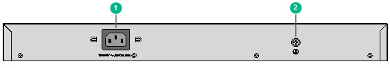
|
(1) AC power receptacle |
(2) Grounding screw |
WX3010H-X-PWR
Figure5-3 Front panel
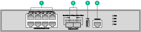
|
(1) 2.5G/1000/100BASE-T PoE+ autosensing Ethernet ports 1 through 8 |
|
|
(2) 10GBASE-R SFP+ autosensing ports 9 and 10 |
|
|
(3) USB port |
(4) Console port |
Figure5-4 Rear panel
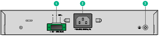
|
(1) DC power receptacle |
(2) AC power receptacle |
|
(3) Grounding screw |
|
WX3010H-L-PWR
Figure5-5 Front panel
|
(1) 100/1000BASE-T PoE+ autosensing Ethernet ports 1 through 8 |
|
|
(2) 100/1000BASE-T autosensing Ethernet ports 9 and 10 |
|
|
(3) 1000BASE-X SFP ports 11 and 12 |
(4) USB port |
|
(5) Console port |
|
Figure5-6 Rear panel

|
(1) AC power receptacle |
(2) Grounding screw |
|
(3) Kensington security slot |
|
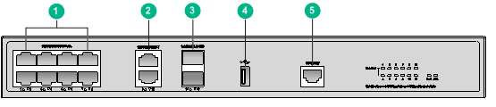
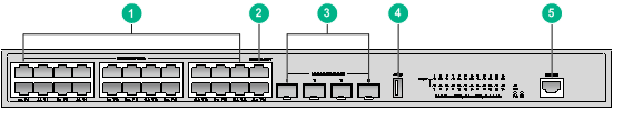
WX3024H
Figure5-7 Front panel

|
(1) 100/1000BASE-T PoE+ autosensing Ethernet ports 1 through 24 |
|
|
(2) 10GBASE-R SFP+ autosensing ports 25 and 26 |
(3) 1000BASE-X SFP ports 27 and 28 (combo ports) |
|
(4) 100/1000BASE-T autosensing Ethernet ports 27 and 28 (combo ports) |
|
|
(5) USB port |
(6) Console port |
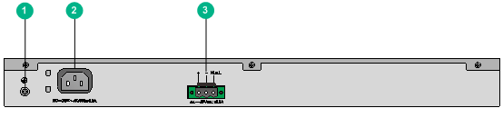
Figure5-8 Rear panel
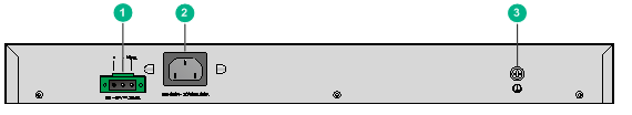
|
(1) DC power receptacle |
(2) AC power receptacle |
|
(3) Grounding screw |
|
WX3024H-L-PWR
Figure5-9 Front panel
|
(1) 100/1000BASE-T PoE+ autosensing Ethernet ports 1 through 22 (combo ports: ports 21 and 22) |
|
|
(2) 100/1000BASE-T autosensing Ethernet ports 23 and 24 (combo ports) |
|
|
(3) 1000BASE-X SFP ports 21 through 24 (combo ports) |
|
|
(4) USB port |
(5) Console port |
Figure5-10 Rear panel
|
(1) Grounding screw |
(2) AC power receptacle |
|
(3) DC power receptacle |
|
Interface numbering
WX3010H
Ports on a WX3010H access controller are numbered as follows:
· Ports marked 1 through 8 are 100/1000BASE-T PoE+ autosensing Ethernet ports, represented by interface number GigabitEthernet 1/0/1 through GigabitEthernet 1/0/8, respectively.
· Ports marked 9 and 10 are 1000BASE-X SFP ports, represented by interface number GigabitEthernet 1/0/9 and GigabitEthernet 1/0/10, respectively.
· Ports marked 11 and 12 are combo ports, represented by interface number GigabitEthernet 1/0/11 and GigabitEthernet 1/0/12, respectively. Each combo interface contains a 1000BASE-X SFP port and a 100/1000BASE-T autosensing Ethernet port. Only one port of a combo interface is active at a time.
Ports marked 1 to 10 are LAN ports. Ports marked 11 and 12 are WAN ports.
WX3010H-X-PWR
Ports on a WX3010H-X-PWR access controller are numbered as follows:
· Ports marked 1 through 8 are 2.5G/1000/100BASE-T PoE+ autosensing Ethernet ports, represented by interface number Smartrate-Ethernet 1/0/1 through Smartrate-Ethernet 1/0/8, respectively.
· Ports marked 9 and 10 are 10G/1GBASE-R SFP+/SFP autosensing Ethernet ports, represented by interface number Ten-GigabitEthernet 1/0/9 and Ten-GigabitEthernet 1/0/10, respectively.
All these ports are LAN ports.
WX3010H-L-PWR
Ports on a WX3010H-L-PWR access controller are numbered as follows:
· Ports marked 1 through 10 are 100/1000BASE-T autosensing Ethernet ports, represented by interface number GigabitEthernet 1/0/1 through GigabitEthernet 1/0/10, respectively.
· Ports marked 11 and 12 are 1000BASE-X SFP ports, represented by interface number GigabitEthernet 1/0/11 and GigabitEthernet 1/0/12, respectively.
All these ports are LAN ports.
WX3024H
Ports on a WX3024H access controller are numbered as follows:
· Ports marked 1 through 24 are 100/1000BASE-T PoE+ autosensing Ethernet ports, represented by interface number GigabitEthernet 1/0/1 through GigabitEthernet 1/0/24, respectively.
· Ports marked 25 and 26 are 10G/1GBASE-R SFP+/SFP autosensing ports, represented by interface number Ten-GigabitEthernet 1/0/25 and Ten-GigabitEthernet 1/0/26, respectively.
· Ports marked 27 and 28 are combo ports, represented by interface number GigabitEthernet 1/0/27 and GigabitEthernet 1/0/28, respectively. Each combo interface contains a 1000BASE-X SFP port and a 100/1000BASE-T autosensing Ethernet port. Only one port of a combo interface is active at a time.
Ports marked 1 through 26 are LAN ports. Ports marked 27 and 28 are WAN ports.
WX3024H-L-PWR
Ports on a WX3024H-L-PWR access controller are numbered as follows:
· Ports marked 1 through 20 are 100/1000BASE-T PoE+ autosensing Ethernet ports, represented by interface number GigabitEthernet 1/0/1 through GigabitEthernet 1/0/20, respectively.
· Ports marked 21 through 24 are combo ports, represented by interface number GigabitEthernet 1/0/21 through GigabitEthernet 1/0/24, respectively. Each combo interface contains a 100/1000BASE-T autosensing Ethernet port and a 1000BASE-X-SFP port. Only one port of a combo interface is active at a time.
All these ports are LAN ports.
Technical specifications
Table5-1 WX3010H technical specifications
|
Item |
WX3010H |
|
Console port |
One, 9600 bps (default) to 115200 bps |
|
Gigabit Ethernet port |
8 × 100/1000BASE-T PoE+ autosensing Ethernet port |
|
SFP port |
· 2 × 1000BASE-X SFP port · 2 × combo 1000BASE-X SFP port |
|
Memory |
2 GB DDR3 |
|
Storage media |
2 × 8MB NOR flash, 1GB NAND flash |
|
Dimensions (H × W × D) (excluding rubber feet) |
43.6 × 440 × 260 mm (1.72 × 17.32 × 10.24 in) |
|
AC input voltage |
· Rated voltage range: 100 to 240 VAC @ 50/60 Hz · Max voltage range: 90 to 264 VAC @ 47 to 63 Hz |
|
System power consumption |
27 W to 50 W |
|
Number of ports that support PoE+ |
8 |
|
Max. output capacity per PoE+ port |
30 W |
|
Max. PoE+ output capacity of the chassis |
196 W (allows six PoE+ ports to provide the max. PoE+ output concurrently) |
|
Weight |
4.5 kg (9.92 lb) |
|
Operating temperature |
0°C to 45°C (32°F to 113°F) |
|
Relative humidity (noncondensing) |
5% RH to 95% RH |
Table5-2 WX3010H-X-PWR technical specifications
|
Item |
WX3010H-X-PWR |
|
Console port |
One, 9600 bps (default) to 115200 bps |
|
Gigabit Ethernet port |
8 × 2.5G/1000/100BASE-T PoE+ autosensing Ethernet port |
|
SFP port |
2 × 10G/1GBASE-R SFP+/SFP autosensing port |
|
Memory |
2 × 2GB DDR3 |
|
Storage media |
4GB CF card |
|
Dimensions (H × W × D) (excluding rubber feet) |
43.6 × 270 × 440 mm (1.72 × 10.63 × 17.32 in) |
|
AC input voltage |
· Rated voltage range: 100 to 240 VAC @ 50/60 Hz · Max voltage range: 90 to 264 VAC @ 47 to 63 Hz |
|
DC input voltage |
· Rated voltage range: –54 to –57 VDC · Max voltage range: –44 to –60 VDC |
|
System power consumption |
64 W to 103 W |
|
Number of ports that support PoE+ |
8 |
|
Max. output capacity per PoE+ port |
35 W |
|
Max. PoE+ output capacity of the chassis |
· AC input: 280 W (allows all the eight PoE+ ports to provide the max. PoE+ output concurrently) · DC input (RPS power source): Allows all the eight PoE+ ports to provide the max. PoE+ output concurrently) |
|
Weight |
5.5 kg (12.13 lb) |
|
Operating temperature |
0°C to 45°C (32°F to 113°F) |
|
Relative humidity (noncondensing) |
5% RH to 95% RH |
Table5-3 WX3010H-L-PWR technical specifications
|
Item |
WX3010H-L-PWR |
|
Console port |
One, 9600 bps (default) to 115200 bps |
|
Gigabit Ethernet port |
10 × 100/1000BASE-T autosensing Ethernet port |
|
SFP port |
2 × 1000BASE-X SFP port |
|
Memory |
1GB DDR3 |
|
Storage media |
1GB NAND flash |
|
Dimensions (H × W × D) (excluding rubber feet) |
43.6 × 330 × 230 mm (1.72 × 12.99 × 9.06 in) |
|
AC input voltage |
· Rated voltage range: 100 to 240 VAC @ 50/60 Hz · Max voltage range: 90 to 264 VAC @ 47 to 63 Hz |
|
System power consumption |
14.5 W to 21 W |
|
Number of ports that support PoE+ |
8 |
|
Max. output capacity per PoE+ port |
30 W |
|
Max. PoE+ output capacity of the chassis |
196 W (allows only six of the PoE+ ports to provide the max. PoE+ output concurrently) |
|
Weight |
2.25 kg (4.96 lb) |
|
Operating temperature |
0°C to 45°C (32°F to 113°F) |
|
Relative humidity (noncondensing) |
5% RH to 95% RH |
Table5-4 WX3024H technical specifications
|
Item |
WX3024H |
|
Console port |
One, 9600 bps (default) to 115200 bps |
|
Gigabit Ethernet port |
24 × 100/1000BASE-T PoE+ autosensing Ethernet port |
|
SFP port |
· 2 × 10G/1GBASE-R SFP+/SFP autosensing port · 2 × combo 1000BASE-X SFP port |
|
Memory |
2GB DDR3 |
|
Storage media |
2 × 8MB NOR flash, 1GB NAND flash |
|
Dimensions (H × W × D) (excluding rubber feet) |
43.6 × 440 × 400 mm (1.72 × 17.32 × 15.75 in) |
|
AC input voltage |
· Rated voltage range: 100 to 240 VAC @ 50/60 Hz · Max voltage range: 90 to 264 VAC @ 47 to 63 Hz |
|
DC input voltage |
· Rated voltage range: –54 to –57 VDC · Max voltage range: –44 to –60 VDC |
|
System power consumption |
40 W to 70 W |
|
Number of ports that support PoE+ |
24 |
|
Max. output capacity per PoE+ port |
30 W |
|
Max. PoE+ output capacity of the chassis |
· AC input: 370 W (allows 12 PoE+ ports to provide the max. PoE+ output concurrently) · DC input (RPS power source): Allows all the 24 PoE+ ports to provide the max. PoE+ output concurrently) |
|
Weight |
6.5 kg (14.33 lb) |
|
Operating temperature |
0°C to 45°C (32°F to 113°F) |
|
Relative humidity (noncondensing) |
5% RH to 95% RH |
Table5-5 WX3024H-L-PWR technical specifications
|
Item |
WX3024H-L-PWR |
|
Console port |
One, 9600 bps (default) to 115200 bps |
|
Gigabit Ethernet port |
24 × 100/1000BASE-T autosensing Ethernet port |
|
SFP port |
4 × 1000BASE-X SFP port (Each forms a combo interface with its corresponding 100/1000BASE-T autosensing Ethernet port.) |
|
Memory |
1GB DDR3 |
|
Storage media |
1GB NAND flash |
|
Dimensions (H × W × D) (excluding rubber feet) |
43.6 × 440 × 260 mm (1.72 × 17.32 × 10.24 in) |
|
AC input voltage |
· Rated voltage range: 100 to 240 VAC @ 50/60 Hz · Max voltage range: 90 to 264 VAC @ 47 to 63 Hz |
|
DC input voltage |
· Rated voltage range: –54 to –57 VDC · Max voltage range: –44 to –60 VDC |
|
System power consumption |
19 W to 31.4 W |
|
Number of ports that support PoE+ |
22 |
|
Max. output capacity per PoE+ port |
30 W |
|
Max. PoE+ output capacity of the chassis |
· AC input: 360 W (allows 12 PoE+ ports to supply the max. PoE+ output concurrently) · DC input (RPS power source): Allows all the 22 PoE+ ports to provide the max. PoE+ output concurrently) |
|
Weight |
4.25 kg (9.37 lb) |
|
Operating temperature |
0°C to 45°C (32°F to 113°F) |
|
Relative humidity (noncondensing) |
5% RH to 95% RH |
Transceiver module, fiber connector, and optical fiber views
To connect a fiber port on the device, use an SFP or SFP+ transceiver module and an optical fiber with LC connectors.
Figure5-11 SFP transceiver module
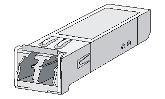
Figure5-12 SFP+ transceiver module
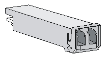
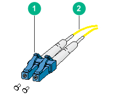
Figure5-13 Optical fiber with LC connectors
|
(1) LC connector |
(2) Optical fiber |
Transceiver module specifications
The transceiver modules whose names contain MM and SM support multi-mode optical fibers and single-mode optical fibers, respectively.
Table5-6 Transceiver modules available for the access controllers
|
Device model |
Available transceiver modules |
|
WX3010H |
· SFP-GE-SX-MM850-A (see Table5-7 ) · SFP-GE-LX-SM1310-A (see Table5-8) · SFP-GE-LH40-SM1310 (see Table5-9) · SFP-GE-LH40-SM1550 (see Table5-10) · SFP-GE-LH80-SM1550 (see Table5-11) |
|
WX3010H-X-PWR |
· SFP-GE-SX-MM850-A (see Table5-7) · SFP-GE-LX-SM1310-A (see Table5-8) · SFP-GE-LH40-SM1310 (see Table5-9) · SFP-GE-LH40-SM1550 (see Table5-10) · SFP-GE-LH80-SM1550 (see Table5-11) · SFP-XG-LX220-MM1310 (see Table5-12) · SFP-XG-LH40-SM1550 (see Table5-13) · SFP-XG-LX-SM1310 (see Table5-14) · SFP-XG-LX-SM1310-E (see Table5-15) · SFP-XG-SX-MM850-A (see Table5-16) · SFP-XG-SX-MM850-E (see Table5-17) |
|
WX3010H-L-PWR |
· SFP-GE-SX-MM850-A (see Table5-7 ) · SFP-GE-LX-SM1310-A (see Table5-8) · SFP-GE-LH40-SM1310 (see Table5-9) · SFP-GE-LH40-SM1550 (see Table5-10) |
|
WX3024H |
· SFP-GE-SX-MM850-A (see Table5-7 ) · SFP-GE-LX-SM1310-A (see Table5-8) · SFP-GE-LH40-SM1310 (see Table5-9) · SFP-GE-LH40-SM1550 (see Table5-10) · SFP-GE-LH80-SM1550 (see Table5-11) · SFP-XG-LX-SM1310 (see Table5-14) · SFP-XG-LX-SM1310-E (see Table5-15) · SFP-XG-SX-MM850-A (see Table5-16) · SFP-XG-SX-MM850-E (see Table5-17) |
|
WX3024H-L-PWR |
· SFP-GE-SX-MM850-A (see Table5-7 ) · SFP-GE-LX-SM1310-A (see Table5-8) · SFP-GE-LH40-SM1310 (see Table5-9) · SFP-GE-LH40-SM1550 (see Table5-10) |
Table5-7 SFP-GE-SX-MM850-A specifications
|
Item |
Specification |
|
Central wavelength |
850 nm |
|
Max transmission distance |
550 m (1804.46 ft) |
|
Data rate |
1250 Mbps |
|
Connector type |
Duplex LC |
|
Fiber mode |
MMF |
|
Fiber diameter |
50 µm |
|
Transmit power |
–9.5 to 0 dBm |
|
Receive sensitivity |
≤ –17 dBm |
|
Saturation |
≤ –3 dBm |
Table5-8 SFP-GE-LX-SM1310-A specifications
|
Item |
Specification |
|
Central wavelength |
1310 nm |
|
Max transmission distance |
10 km (6.21 miles) |
|
Data rate |
1250 Mbps |
|
Connector type |
Duplex LC |
|
Fiber mode |
SMF |
|
Fiber diameter |
9 µm |
|
Transmit power |
–9.5 to –3 dBm |
|
Receive sensitivity |
≤ –20 dBm |
|
Saturation |
≤ –3 dBm |
Table5-9 SFP-GE-LH40-SM1310 specifications
|
Item |
Specification |
|
Central wavelength |
1310 nm |
|
Max transmission distance |
40 km (24.86 miles) |
|
Data rate |
1250 Mbps |
|
Connector type |
Duplex LC |
|
Fiber mode |
SMF |
|
Fiber diameter |
9 µm |
|
Transmit power |
–2 to +5 dBm |
|
Receive sensitivity |
≤ –22 dBm |
|
Saturation |
≤ –3 dBm |
Table5-10 SFP-GE-LH40-SM1550 specifications
|
Item |
Specification |
|
Central wavelength |
1550 nm |
|
Max transmission distance |
40 km (24.86 miles) |
|
Data rate |
1250 Mbps |
|
Connector type |
Duplex LC |
|
Fiber mode |
SMF |
|
Fiber diameter |
9 µm |
|
Transmit power |
–4 to +1 dBm |
|
Receive sensitivity |
≤ –21 dBm |
|
Saturation |
≤ –3 dBm |
Table5-11 SFP-GE-LH80-SM1550 specifications
|
Item |
Specification |
|
Central wavelength |
1550 nm |
|
Max. transmission distance |
80 km (49.71 miles) |
|
Data rate |
1250 Mbps |
|
Connector type |
Duplex LC |
|
Fiber mode |
SMF |
|
Fiber diameter |
9 µm |
|
Transmit power |
–4 to +5 dBm |
|
Receive sensitivity |
≤ –22 dBm |
|
Saturation |
≤ –3 dBm |
Table5-12 SFP-XG-LX220-MM1310 specifications
|
Item |
Specification |
|
Central wavelength |
1310 nm |
|
Max. transmission distance |
220 m (721.78 ft) |
|
Data rate |
10.31 Gbps |
|
Connector type |
Duplex LC |
|
Fiber mode |
MMF |
|
Fiber diameter |
62.5 µm |
|
Transmit power |
–6.5 to +0.5 dBm |
|
Receive sensitivity |
≤ –6.5 dBm |
|
Saturation |
≤ +1.5 dBm |
Table5-13 SFP-XG-LH40-SM1550 specifications
|
Item |
Specification |
|
Central wavelength |
1550 nm |
|
Max. transmission distance |
40 km (24.86 miles) |
|
Data rate |
10.31 Gbps |
|
Connector type |
Duplex LC |
|
Fiber mode |
SMF |
|
Fiber diameter |
9 µm |
|
Transmit power |
–4.7 to +4 dBm |
|
Receive sensitivity |
≤ –15.8 dBm |
|
Saturation |
≤ –1 dBm |
Table5-14 SFP-XG-LX-SM1310 specifications
|
Item |
Specification |
|
Central wavelength |
1310 nm |
|
Max transmission distance |
10 km (6.21 miles) |
|
Data rate |
10.31 Gbps |
|
Connector type |
Duplex LC |
|
Fiber mode |
SMF |
|
Fiber diameter |
9 µm |
|
Transmit power |
–8.2 to +0.5 dBm |
|
Receive sensitivity |
≤ –14.4 dBm |
|
Saturation |
≤ +0.5 dBm |
Table5-15 SFP-XG-LX-SM1310-E specifications
|
Item |
Specification |
|
Central wavelength |
1310 nm |
|
Max transmission distance |
10 km (6.21 miles) |
|
Data rate |
10.31 Gbps |
|
Connector type |
Duplex LC |
|
Fiber mode |
SMF |
|
Fiber diameter |
9 µm |
|
Transmit power |
–8.2 to +0.5 dBm |
|
Receive sensitivity |
≤ –14.4 dBm |
|
Saturation |
≤ +0.5 dBm |
Table5-16 SFP-XG-SX-MM850-A specifications
|
Item |
Specification |
|
Central wavelength |
850 nm |
|
Max transmission distance |
300 m (984.25 ft) |
|
Data rate |
10.31 Gbps |
|
Connector type |
Duplex LC |
|
Fiber mode |
MMF |
|
Fiber diameter |
50 µm |
|
Transmit power |
–7.3 to –1 dBm |
|
Receive sensitivity |
≤ –9.9 dBm |
|
Saturation |
≤ +0.5 dBm |
Table5-17 SFP-XG-SX-MM850-E specifications
|
Item |
Specification |
|
Central wavelength |
850 nm |
|
Max transmission distance |
300 m (984.25 ft) |
|
Data rate |
10.31 Gbps |
|
Connector type |
Duplex LC |
|
Fiber mode |
MMF |
|
Fiber diameter |
50 µm |
|
Transmit power |
–7.3 to –1 dBm |
|
Receive sensitivity |
≤ –9.9 dBm |
|
Saturation |
≤ +0.5 dBm |
6 Appendix B LEDs
WX3010H
Figure6-1 Front panel LEDs
|
(1) 100/1000BASE-T PoE+ autosensing Ethernet port status LEDs |
|
|
(2) 1000BASE-X SFP port status LEDs |
|
|
(3) 1000BASE-X SFP port (combo) status LEDs |
|
|
(4) 100/1000BASE-T autosensing Ethernet port (combo) status LEDs |
|
|
(5) System status LED (SYS) |
(6) PoE+ system status LED (PoE) |
|
(7) AC power status LED (PWR) |
|
Table6-1 LED description
|
LED |
Mark |
Status |
Description |
|
System status LED |
SYS |
Flashing green (4 Hz) |
The system is loading software. |
|
Flashing green (0.5 Hz) |
The system is operating correctly. |
||
|
Steady red |
A system exception, such as startup failure, fan failure, or overtemperature, has occurred. |
||
|
Off |
The system is not operating or is in reset state. |
||
|
AC power status LED |
PWR |
Steady green |
AC power is being input and the power module is operating correctly. |
|
Steady red |
The power module is faulty or no AC power is being input. |
||
|
Off |
The device is powered off. |
||
|
PoE system status LED |
PoE |
Steady green |
A PoE+ port is outputting power correctly. |
|
Flashing green |
A PoE+ port is outputting power incorrectly or is overloaded. |
||
|
Off |
No PoE ports are outputting power. |
||
|
100/1000BASE-T autosensing Ethernet port status LED |
N/A |
Steady green |
A 1000 Mbps link is present on the port. |
|
Flashing green |
The port is receiving or transmitting data at 1000 Mbps. |
||
|
Steady yellow |
A 100 Mbps link is present on the port. |
||
|
Flashing yellow |
The port is receiving or transmitting data at 100 Mbps. |
||
|
Off |
No link is present on the port. |
||
|
1000BASE-X SFP port status LED |
N/A |
Steady green |
A 1000 Mbps link is present on the port. |
|
Flashing green |
The port is receiving or transmitting data at 1000 Mbps. |
||
|
Off |
No link is present on the port. |
||
|
Combo 1000BASE-X SFP port status LED |
N/A |
Steady green |
A 1000 Mbps link is present on the port. |
|
Flashing green |
The port is receiving or transmitting data at 1000 Mbps. |
||
|
Off |
No link is present on the port. |
||
|
Combo 100/1000BASE-T autosensing Ethernet port status LED |
N/A |
Steady green |
A 1000 Mbps link is present on the port. |
|
Flashing green |
The port is receiving or transmitting data at 1000 Mbps. |
||
|
Steady yellow |
A 100 Mbps link is present on the port. |
||
|
Flashing yellow |
The port is receiving or transmitting data at 100 Mbps. |
||
|
Off |
No link is present on the port. |
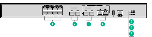
WX3010H-X-PWR
Figure6-2 Front panel LEDs

|
(1) 2.5G/1000/100BASE-T PoE+ autosensing Ethernet port status LEDs |
|
|
(2) 10GBase-R SFP+ autosensing port status LEDs |
(3) AC power status LED (PWR) |
|
(4) DC power status LED (RPS) |
(5) System status LED (SYS) |
|
(6) PoE system status LED (PoE) |
|
|
LED |
Mark |
Status |
Description |
|
System status LED |
SYS |
Flashing green (4 Hz) |
The system is loading software. |
|
Flashing green (0.5 Hz) |
The system is operating correctly. |
||
|
Steady red |
A system exception, such as startup failure, fan failure, or overtemperature, has occurred. |
||
|
Off |
The system is not operating or is in reset state. |
||
|
AC power status LED |
PWR |
Steady green |
AC power is being input and the power module is operating correctly. |
|
Steady red |
The power module is faulty. |
||
|
Off |
The device is powered off. |
||
|
DC power status LED |
RPS |
Steady green |
DC power is being input and the power module is operating correctly. |
|
Steady red |
The power module is faulty or no DC power is being input. |
||
|
Off |
The RPS is powered off. |
||
|
PoE system status LED |
PoE |
Steady green |
A PoE+ port is outputting power correctly. |
|
Flashing green |
A PoE+ port is outputting power incorrectly or is overloaded. |
||
|
Off |
No PoE ports are outputting power. |
||
|
2.5G/1000/100 BASE-T PoE+ autosensing Ethernet port status LED |
N/A |
Steady green |
A 2.5 Gbps link is present on the port. |
|
Flashing green |
The port is receiving or transmitting data at 2.5 Gbps. |
||
|
Steady yellow |
A 1000 or 100 Mbps link is present on the port. |
||
|
Flashing yellow |
The port is receiving or transmitting data at 1000 or 100 Mbps. |
||
|
Off |
No link is present on the port. |
||
|
10G/1GBASE-R SFP+/SFP autosensing port status LED |
N/A |
Steady green |
A 10 Gbps link is present on the port. |
|
Flashing green |
The port is receiving or transmitting data at 10 Gbps. |
||
|
Steady yellow |
A 1 Gbps link is present on the port. |
||
|
Flashing yellow |
The port is receiving or transmitting data at 1 Gbps. |
||
|
Off |
No link is present on the port. |
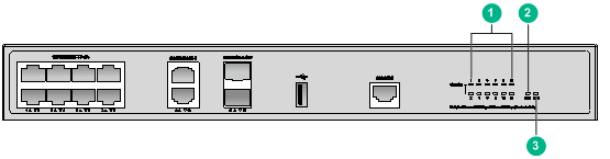
WX3010H-L-PWR
Figure6-3 Front panel LEDs
|
(1) Ethernet port status LEDs (Link/Act) |
(2) PoE system status LED (PoE) |
|
(3) System status LED (SYS) |
|
Table6-3 LED description
|
LED |
Mark |
Status |
Description |
|
System status LED |
SYS |
Flashing green (4 Hz) |
The system is loading software. |
|
Flashing green (0.5 Hz) |
The system is operating correctly. |
||
|
Steady red |
A system exception, such as startup failure, fan failure, or overtemperature, has occurred. |
||
|
Off |
The system is not operating or is in reset state. |
||
|
PoE system status LED |
PoE |
Steady green |
A PoE port is outputting power correctly. |
|
Flashing green |
A PoE port is outputting power incorrectly or is overloaded. |
||
|
Off |
No PoE ports are outputting power. |
||
|
Ethernet port status LED |
Link/Act |
Steady green |
A 1000 Mbps link is present on the port. |
|
Flashing green |
The port is sending or receiving data at 1000 Mbps. |
||
|
Steady yellow |
A 100 Mbps link is present on the port. |
||
|
Flashing yellow |
The port is receiving or transmitting data at 100 Mbps. |
||
|
Off |
No link is present on the port. |
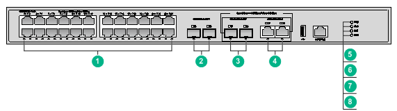
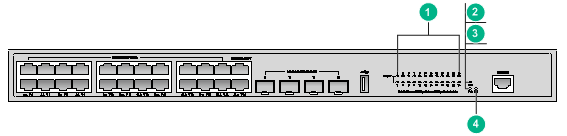
WX3024H
Figure6-4 Front panel LEDs
|
(1) 100/1000BASE-T PoE+ autosensing Ethernet port status LEDs |
|
|
(2) 10GBASE-R SFP+ autosensing port status LEDs |
|
|
(3) 1000BASE-X SFP port (combo) status LEDs |
|
|
(4) 100/1000BASE-T autosensing Ethernet port (combo) status LEDs |
|
|
(5) AC power status LED (PWR) |
(6) System status LED (SYS) |
|
(7) PoE system status LED (PoE) |
(8) DC power status LED (RPS) |
Table6-4 LED description
|
LED |
Mark |
Status |
Description |
|
System status LED |
SYS |
Flashing green (4 Hz) |
The system is loading software. |
|
Flashing green (0.5 Hz) |
The system is operating correctly. |
||
|
Steady red |
A system exception, such as startup failure, fan failure, or overtemperature, has occurred. |
||
|
Off |
The system is not operating or is in reset state. |
||
|
AC power status LED |
PWR |
Steady green |
AC power is being input and the power module is operating correctly. |
|
Steady red |
The power module is faulty. |
||
|
Off |
The device is powered off. |
||
|
DC power status LED |
RPS |
Steady green |
DC power is being input and the power module is operating correctly. |
|
Steady red |
The power module is faulty or no DC power is being input. |
||
|
Off |
The RPS is powered off. |
||
|
PoE system status LED |
PoE |
Steady green |
A PoE+ port is outputting power correctly. |
|
Flashing green |
A PoE+ port is outputting power incorrectly or is overloaded. |
||
|
Off |
No PoE ports are outputting power. |
||
|
100/1000BASE-T autosensing Ethernet port status LED |
N/A |
Steady green |
A 1000 Mbps link is present on the port. |
|
Flashing green |
The port is receiving or transmitting data at 1000 Mbps. |
||
|
Steady yellow |
A 100 Mbps link is present on the port. |
||
|
Flashing yellow |
The port is receiving or transmitting data at 100 Mbps. |
||
|
Off |
No link is present on the port. |
||
|
10GBASE-R SFP+/SFP port status LED |
N/A |
Steady green |
A 10 Gbps link is present on the port. |
|
Flashing green |
The port is receiving or transmitting data at 10 Gbps. |
||
|
Steady yellow |
A 1 Gbps link is present on the port. |
||
|
Flashing yellow |
The port is receiving or transmitting data at 1 Gbps. |
||
|
Off |
No link is present on the port. |
||
|
Combo 1000BASE-X SFP port status LED |
N/A |
Steady green |
A 1000 Mbps link is present on the port. |
|
Flashing green |
The port is receiving or transmitting data at 1000 Mbps. |
||
|
Off |
No link is present on the port. |
||
|
Combo 100/1000BASE-T autosensing Ethernet port status LED |
N/A |
Steady green |
A 1000 Mbps link is present on the port. |
|
Flashing green |
The port is receiving or transmitting data at 1000 Mbps. |
||
|
Steady yellow |
A 100 Mbps link is present on the port. |
||
|
Flashing yellow |
The port is receiving or transmitting data at 100 Mbps. |
||
|
Off |
No link is present on the port. |
WX3024H-L-PWR
Figure6-5 Front panel LEDs
|
(1) Ethernet port status LEDs (Link/Act) |
(2) DC power status LED (RPS) |
|
(3) PoE system status LED (PoE) |
(4) System status LED (SYS) |
Table6-5 LED description
|
LED |
Mark |
Status |
Description |
|
System status LED |
SYS |
Flashing green (4 Hz) |
The system is loading software. |
|
Flashing green (0.5 Hz) |
The system is operating correctly. |
||
|
Steady red |
A system exception, such as startup failure, fan failure, or overtemperature, has occurred. |
||
|
Off |
The system is not operating or is in reset state. |
||
|
DC power status LED |
RPS |
Steady green |
DC power is being input and the power module is operating correctly. |
|
Steady red |
The power module is faulty or no DC power is being input. |
||
|
Off |
The RPS is powered off. |
||
|
PoE system status LED |
PoE |
Steady green |
A PoE+ port is outputting power correctly. |
|
Flashing green |
A PoE+ port is outputting power incorrectly or is overloaded. |
||
|
Off |
No PoE+ ports are outputting power. |
||
|
Ethernet port status LED |
Link/Act |
Steady green |
A 1000 Mbps link is present on the port. |
|
Flashing green |
The port is sending or receiving data at 1000 Mbps. |
||
|
Steady yellow |
A 100 Mbps link is present on the port. |
||
|
Flashing yellow |
The port is receiving or transmitting data at 100 Mbps. |
||
|
Off |
No link is present on the port. |
