| Title | Size | Downloads |
|---|---|---|
| 02-IRF Configuration Guide-book.pdf | 734.72 KB |
- Table of Contents
Contents
IRF connection error notification
Multi-active handling procedure
General restrictions and configuration guidelines
IRF size and member ID restrictions
IRF physical interface restrictions
Feature compatibility and configuration restrictions
MAD and IRF domain restrictions
Setup and configuration task list
Preconfiguring IRF member devices in standalone mode
Assigning a member ID to each IRF member device
Specifying a priority for each member device
Binding physical interfaces to IRF ports
Saving configuration to the next-startup configuration file
Connecting IRF physical interfaces
Setting the operating mode to IRF mode
Configuring IRF member devices in IRF mode
Assigning an IRF domain ID to the IRF fabric
Changing the member ID of a device
Changing the priority of a member device
Adding physical interfaces to an IRF port
Configuring a member device description
Configuring IRF link load sharing mode
Configuring the IRF bridge MAC address
Configuring IRF bridge MAC persistence
Enabling software auto-update for system software image synchronization
Setting the IRF link down report delay
Displaying and maintaining an IRF fabric
LACP MAD-enabled IRF configuration example
BFD MAD-enabled IRF configuration example
Configuration example for restoring standalone mode
The H3C Intelligent Resilient Framework (IRF) technology creates a large IRF fabric from multiple devices to provide data center class availability and scalability. IRF virtualization technology offers processing power, interaction, unified management, and uninterrupted maintenance of multiple devices.
This book describes IRF concepts and guides you through the IRF setup procedure.
Hardware compatibility
An H3C S9800 switch can form an IRF fabric only with devices of the same model.
IRF benefits
IRF provides the following benefits:
· Simplified topology and easy management—An IRF fabric appears as one node and is accessible at a single IP address on the network. You can use this IP address to log in at any member device to manage all the members of the IRF fabric. In addition, you do not need to run the spanning tree feature among the IRF members.
· 1:N redundancy—In an IRF fabric, one member works as the master to manage and control the entire IRF fabric. All other members process services while backing up the master. When the master fails, all the other member devices elect a new master from among them to take over without interrupting services.
· IRF link aggregation—You can assign several physical links between neighboring members to their IRF ports to create a load-balanced aggregate IRF connection with redundancy.
· Multiple-chassis link aggregation—You can use the Ethernet link aggregation feature to aggregate the physical links between the IRF fabric and its upstream or downstream devices across the IRF members.
· Network scalability and resiliency—Processing capacity of an IRF fabric equals the total processing capacities of all the members. You can increase ports, network bandwidth, and processing capacity of an IRF fabric simply by adding member devices without changing the network topology.
Application scenario
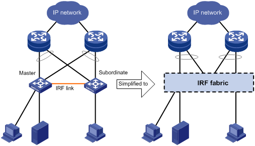
Figure 1 shows an IRF fabric that has two devices, which appear as a single node to the upper-layer and lower-layer devices.
Figure 1 IRF application scenario
Network topologies
The H3C S9800 IRF fabric only supports the daisy-chain topology. For information about connecting IRF member devices, see "Connecting IRF physical interfaces."
Basic concepts
This section uses Figure 2 and Figure 3 to describe the basic concepts that you might encounter when you work with IRF.
Figure 2 S9804 IRF fabric implementation schematic diagram
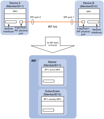
In this figure, Device A and Device B form a two-chassis IRF fabric. The fabric has two MPUs (one active and one standby), and two times the number of LPUs that a single device provides. The IRF fabric manages the physical and software resources of Device A and Device B in a centralized manner.
Figure 3 S9810 IRF fabric implementation schematic diagram
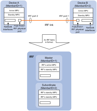
In this figure, Device A and Device B form a two-chassis IRF fabric. The fabric has four MPUs (one active and three standbys), and two times the number of LPUs that a single device provides. The IRF fabric manages the physical and software resources of Device A and Device B in a centralized manner.
Operating mode
The device operates in one of the following modes:
· Standalone mode—The device cannot form an IRF fabric with other devices.
· IRF mode—The device can form an IRF fabric with other devices.
IRF member roles
IRF uses two member roles: master and standby (called subordinate throughout the documentation).
When devices form an IRF fabric, they elect a master to manage the IRF fabric, and all other devices back up the master. When the master device fails, the other devices automatically elect a new master. For more information about master election, see "Master election."
IRF member ID
An IRF fabric uses member IDs to uniquely identify and manage its members. If two devices have the same IRF member ID, they cannot form an IRF fabric. If the IRF member ID of a device has been used in an IRF fabric, the device cannot join the fabric.
Member ID information is included as the first part of interface numbers and file paths to uniquely identify interfaces and files in an IRF fabric. For example, after you assign a device with member ID 2 to an IRF fabric, the name of interface FortyGigE 3/0/1 changes to FortyGigE 2/3/0/1. The file path changes from slot0#flash:/test.cfg to chassis2#slot0#flash:/test.cfg.
MPU roles
The S9804 switch uses one built-in MPU (slot 0) and the S9810 switch uses two removable switching fabric modules (slots 10 and 11) for switching and control.
Unless otherwise stated, the term "MPU" collectively refers to the switching fabric modules on the S9810 switch and the built-in MPU on the S9804 switch.
The following are MPU roles:
|
Role |
Description |
|
Master MPU |
Active MPU of the master device. It is also called the global active MPU. You configure and manage the entire IRF fabric at the CLI of the global active MPU. |
|
Active MPU |
Active MPU on each member device. An active MPU performs the following operations: · Manages the local device, including synchronizing configuration with the local standby MPU, processing protocol packets, and creating and maintaining route entries. · Processes IRF-related events, such as master election and topology collection. |
|
Standby MPU |
For the master MPU, all other MPUs are standby MPUs, including active MPUs on subordinate devices. If a member device has two MPUs, the MPU backing up the local active MPU is the local standby MPU from the perspective of the member device. |
IRF port
An IRF port is a logical interface that connects IRF member devices. Every IRF-capable device supports two IRF ports.
In standalone mode, the IRF ports are named IRF-port 1 and IRF-port 2.
In IRF mode, the IRF ports are named IRF-port n/1 and IRF-port n/2, where n is the member ID of the device. The two IRF ports are referred to as IRF-port 1 and IRF-port 2 in this book.
To use an IRF port, you must bind a minimum of one physical interface to it. The physical interfaces assigned to an IRF port automatically form an aggregate IRF link. An IRF port goes down only if all its IRF physical interfaces are down.
For two neighboring devices, their IRF physical links must be bound to IRF-port 1 on one device and to IRF-port 2 on the other.
IRF physical interface
IRF physical interfaces connect IRF member devices and must be bound to an IRF port. They forward the IRF protocol packets between IRF member devices and the data packets that must travel across IRF member devices.
IRF domain ID
One IRF fabric forms one IRF domain. IRF uses IRF domain IDs to uniquely identify IRF fabrics and prevent IRF fabrics from interfering with one another.
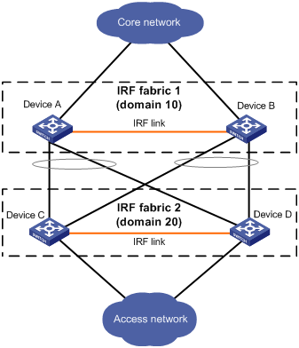
As shown in Figure 4, IRF fabric 1 contains Device A and Device B, and IRF fabric 2 contains Device C and Device D. Both fabrics use the LACP aggregate links between them for MAD. When a member device receives an extended LACPDU for MAD, it checks the domain ID to see whether the packet is from the local IRF fabric. Then, the device can handle the packet correctly.
Figure 4 A network that contains two IRF domains
IRF split
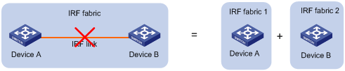
IRF split occurs when an IRF fabric breaks up into multiple IRF fabrics because of IRF link failures, as shown in Figure 5. The split IRF fabrics operate with the same IP address. IRF split causes routing and forwarding problems on the network. To quickly detect a multi-active collision, configure one of the MAD mechanisms (see "IRF multi-active detection").
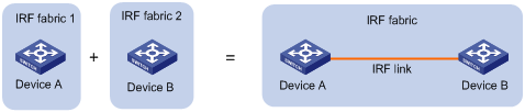
IRF merge
IRF merge occurs when two split IRF fabrics reunite or when two independent IRF fabrics are united, as shown in Figure 6.
Member priority
Member priority determines the possibility of a member device to be elected the master. A member with higher priority is more likely to be elected the master.
Master election
Master election occurs each time the IRF fabric topology changes in the following situations:
· The IRF fabric is established.
· The master device fails or is removed.
· The IRF fabric splits.
· Independent IRF fabrics merge.
|
|
NOTE: Master election does not occur when two split IRF fabrics merge. |
Master election selects a master in descending order:
1. Current master, even if a new member has higher priority.
When an IRF fabric is being formed, all member devices consider themselves as the master. This rule is skipped.
2. Member with higher priority.
3. Member with the longest system uptime.
Two members are considered to start up at the same time if their startup time difference is equal to or less than 10 minutes. For these members, the next tiebreaker applies.
4. Member with the lowest member ID.
For a new IRF fabric, the subordinate devices must reboot to complete the setup after the master election.
For an IRF merge, devices must reboot if they are in the IRF fabric that fails the master election. The reboot can be performed automatically or manually (see "Enabling IRF auto-merge").
After a master election, all subordinate devices reboot with the configuration on the master. The configuration files of the subordinate members are retained, but the files do not take effect in the IRF fabric. A subordinate member uses its own startup configuration file only after it is removed from the IRF fabric.
IRF connection error notification
The device generates error messages when its IRF physical interfaces are connected to non-IRF physical interfaces. The error messages use the form of "The port port can't receive irf pkt and has been changed to inactive status, please check." The port argument represents the interface name of an IRF physical interface that connects to a non-IRF physical interface.
The messages help you identify incorrect IRF connections to avoid issues including cross-chassis packet loss and IRF split.
The error messages might be falsely generated when the IRF fabric is unstable. For example, the messages might occur during an IRF setup, reboot, or IRF port binding modification process. If the IRF connections are correct, the messages will not occur after the IRF fabric completes the process.
Loop elimination mechanism
Loop control protocols such as the spanning tree feature cannot be configured on IRF physical interfaces. However, IRF has its own mechanism to eliminate loops. Before an IRF member device forwards a packet, it identifies whether loops exist on the forwarding path based on the source and destination physical interfaces and the IRF topology. If a loop exists, the device discards the packet on the source interface of the looped path. This loop elimination mechanism will drop a large number of broadcast packets on the IRF physical interfaces. When you use SNMP tools, do not monitor packet forwarding on the IRF physical interfaces to reduce SNMP notifications of packet drops.
IRF multi-active detection
An IRF link failure causes an IRF fabric to split in two IRF fabrics operating with the same Layer 3 configurations, including the same IP address. To avoid IP address collision and network problems, IRF uses multi-active detection (MAD) mechanisms to detect the presence of multiple identical IRF fabrics, handle collisions, and recover from faults.
Multi-active handling procedure
The multi-active handling procedure includes detection, collision handling, and failure recovery.
Detection
The MAD implementation of this device detects active IRF fabrics with the same Layer 3 global configuration by extending the LACP or BFD protocol.
These MAD mechanisms identify each IRF fabric with a domain ID and an active ID (the member ID of the master). If multiple active IDs are detected in a domain, MAD determines that an IRF collision or split has occurred.
|
|
IMPORTANT: LACP MAD handles collisions differently than BFD MAD. To avoid conflicts, do not enable LACP MAD together with BFD MAD. |
For a comparison of the MAD mechanisms, see "Configuring MAD."
Collision handling
When MAD detects a multi-active collision, it allows one IRF fabric to forward traffic and sets all the other IRF fabrics to the Recovery state. The Recovery-state IRF fabrics are inactive and cannot forward traffic.
LACP MAD uses the following process to handle a multi-active collision:
1. Compares the number of members in each fabric.
2. Allows the fabric that has the most members to forward traffic, and sets all other fabrics to the Recovery state.
3. Compares the member IDs of their masters if all IRF fabrics have the same number of members.
4. Allows the IRF fabric that has the lowest numbered master to forward traffic, and sets all other fabrics to the Recovery (inactive) state.
5. Shuts down all physical network ports in the Recovery-state fabrics except for the following ports:
? IRF physical interfaces.
? Ports you have specified with the mad exclude interface command.
In contrast, BFD MAD does not compare the number of members in fabrics. BFD MAD uses the following process to handle a multi-active collision:
1. Allows the IRF fabric that has the lowest numbered master to forward traffic.
2. Sets all other fabrics to the Recovery state.
3. Takes the same action on the network ports in Recovery-state fabrics as LACP MAD.
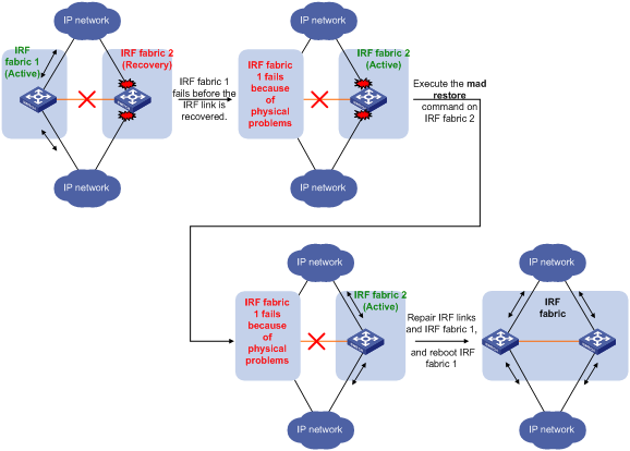
Failure recovery
To merge two split IRF fabrics, first repair the failed IRF link and remove the IRF link failure.
· If the IRF fabric in Recovery state fails before the failure is recovered, repair the failed IRF fabric and the failed IRF link.
· If the active IRF fabric fails before the failure is recovered, enable the inactive IRF fabric to take over the active IRF fabric. Then, recover the MAD failure.
LACP MAD
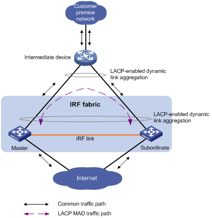
As shown in Figure 7, LACP MAD has the following requirements:
· Every IRF member must have a link with an intermediate device.
· All the links form a dynamic link aggregation group.
· The intermediate device must be an H3C device that supports extended LACP for MAD.
The IRF member devices send extended LACPDUs with a domain ID and an active ID. The intermediate device transparently forwards the extended LACPDUs received from one member device to all the other member devices.
· If the domain IDs and the active IDs in the extended LACPDUs sent by all the member devices are the same, the IRF fabric is integrated.
· If the extended LACPDUs convey the same domain ID but different active IDs, a split has occurred. LACP MAD handles this situation as described in "Collision handling."
BFD MAD
In versions earlier than Release 2138P01, you can use only common Ethernet ports for BFD MAD links. In Release 2138P01 and later versions, you can use common or management Ethernet ports for BFD MAD links.
· If management Ethernet ports are used, BFD MAD has the following requirements:
? Each IRF member device has a BFD MAD link to an intermediate device.
? Each member device is assigned a MAD IP address on the master's management Ethernet port.
· If common Ethernet ports are used, BFD MAD has the following requirements:
? Each member device has a BFD MAD link to an intermediate device, or all member devices have a BFD MAD link to each other.
? Each member device is assigned a MAD IP address on a VLAN interface.
The BFD MAD links must be dedicated. Do not use BFD MAD links for any other purposes.
|
|
NOTE: · The MAD addresses identify the member devices and must belong to the same subnet. · Of all management Ethernet ports on an IRF fabric, only the master's management Ethernet port is accessible. |
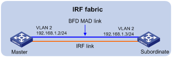
Figure 8 shows a typical BFD MAD scenario that uses an intermediate device. Figure 9 shows a typical BFD MAD scenario that does not use an intermediate device.
With BFD MAD, the master attempts to establish BFD sessions with other member devices by using its MAD IP address as the source IP address.
· If the IRF fabric is integrated, only the MAD IP address of the master takes effect. The master cannot establish a BFD session with any other member. If you execute the display bfd session command, the state of the BFD sessions is Down.
· When the IRF fabric splits, the IP addresses of the masters in the split IRF fabrics take effect. The masters can establish a BFD session. If you execute the display bfd session command, the state of the BFD session between the two devices is Up.
Figure 8 BFD MAD scenario with intermediate device
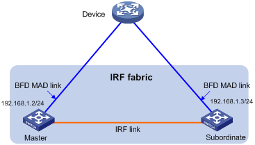
Figure 9 BFD MAD scenario without intermediate device
General restrictions and configuration guidelines
For a successful IRF setup, follow the restrictions and guidelines in this section and the setup procedure in "Setup and configuration task list."
Software requirements
All IRF member devices must run the same system software image version.
IRF size and member ID restrictions
To ensure a successful IRF setup, follow these IRF size and member ID restrictions:
· An H3C S9800 IRF fabric can have a maximum of two chassis.
· The member ID assigned to a member chassis must be 1 or 2.
MPU requirements
Each IRF member device must have a minimum of one MPU.
IRF physical interface restrictions
Use the following physical interfaces for IRF links:
· 10-GE ports.
· 40-GE ports.
· 100-GE ports.
Selecting transceiver modules and cables
When you select transceiver modules and cables, follow these restrictions and guidelines:
· Use SFP+, QSFP+, or CXP transceiver modules and fibers for a long-distance connection.
· Use SFP+, QSFP+, or CXP DAC cables to connect 10-GE, 40-GE, or 100-GE ports for a short-distance connection.
· The transceiver modules at the two ends of an IRF link must be the same type. For more information about transceiver modules, see the device installation guide.
40-GE port restrictions
You can use a 40-GE QSFP+ port as an IRF physical interface, or use the using tengige command to split a QSFP+ port into four 10-GE breakout interfaces.
When you use the 10-GE breakout interfaces of a QSFP+ port for IRF links, follow these restrictions and guidelines:
· The 10-GE breakout interfaces of a 40-GE port are operating independently. You do not need to use all of them for IRF links.
· Port split and combination (the using fortygige command) require a card reboot. As a best practice to avoid topology change, complete these operations before you add the device to an IRF fabric. When you perform these operations in an IRF fabric, make sure you understand the impact on the IRF fabric topology. For more information about 40-GE port split and combination operations, see Layer 2—LAN Switching Configuration Guide.
Physical interface binding requirements
When you bind an IRF physical interface to an IRF port, follow these guidelines:
· In IRF mode, use the shutdown command to shut down the physical interface before you bind it to or remove it from the IRF port. Use the undo shutdown command to bring up the physical interface after a binding or binding removal operation.
· In standalone mode, the shutdown and undo shutdown operations are not required.
Connecting IRF ports
When you connect two neighboring IRF members, follow these restrictions and guidelines:
· You must connect the physical interfaces of IRF-port 1 on one member to the physical interfaces of IRF-port 2 on the other.
· Do not connect physical interfaces of both IRF ports on one member device to the physical interfaces of both IRF ports on the other device.
IRF link redundancy
When you configure an IRF fabric, follow these link redundancy guidelines:
· For link redundancy and load sharing, bind a maximum of eight physical interfaces to one IRF port.
· Physical interfaces bound to an IRF port can be located on different cards. As a best practice, use multicard IRF links to prevent a card removal from causing an IRF split.
Multichassis link aggregation
For high availability, connect a downstream device to each IRF member device, and assign the links to one link aggregation group.
Feature compatibility and configuration restrictions
System operating mode
All member devices in the IRF fabric must work in the same system operating mode (set by using the system-working-mode command). For more information about the system operating mode, see Fundamentals Configuration Guide.
Maximum number of ECMP routes
All member devices in the IRF fabric must have the same setting for the maximum number of ECMP routes. For more information about configuring ECMP, see Layer 3—IP Routing Configuration Guide.
MDC
If the IRF fabric splits, do not change the MDC settings on any IRF member devices before they reunite.
Except for the commands in Table 1, all IRF commands are available only on the default MDC.
Table 1 IRF commands available on both default and non-default MDCs
|
Command category |
Commands |
|
Display commands |
display irf link |
|
MAD commands |
mad bfd enable mad enable mad exclude interface mad ip address |
For more information about MDCs, see Fundamentals Configuration Guide.
MAD and IRF domain restrictions
When you configure MAD, follow these restrictions and guidelines:
· If LACP MAD or BFD MAD runs between two IRF fabrics, assign each fabric a unique IRF domain ID.
· An IRF fabric has only one IRF domain ID.
? You can change the IRF domain ID by using the irf domain or mad enable command. The IRF domain IDs configured by using these commands overwrite each other.
? In an MDC environment, if you change the IRF domain ID in one MDC, the IRF domain IDs in all other MDCs change automatically. The irf domain command is available only on the default MDC. The mad enable command is available on any MDCs.
· LACP MAD handles collisions differently than BFD MAD. To avoid conflicts, do not enable LACP MAD together with BFD MAD in an IRF fabric.
· To prevent a port from being shut down when the IRF fabric transits to the Recovery state, use the mad exclude interface command. To bring up ports in a Recovery-state IRF fabric, use the mad restore command instead of the undo shutdown command. The mad restore command activates the Recovery-state IRF fabric.
IRF merge restrictions
If the IRF fabric splits, do not change the IRF settings on any IRF member devices before they reunite.
Configuration backup
As a best practice, back up the next-startup configuration file on a device before adding the device to an IRF fabric as a subordinate device.
A subordinate device's next-startup configuration file might be overwritten if the master and the subordinate use the same file name for their next-startup configuration files. You can use the backup file to restore the original configuration after removing the subordinate from the IRF fabric.
Setup and configuration task list
As a best practice, use the following IRF fabric setup and configuration procedure:
Planning the IRF fabric setup
Consider the following items when you plan an IRF fabric:
· Hardware compatibility and restrictions.
· IRF fabric size.
· Master device.
· IRF physical interfaces.
· Member ID and priority assignment scheme.
· Fabric topology and cabling scheme.
For more information about hardware and cabling, see the installation guide for the device.
Preconfiguring IRF member devices in standalone mode
Perform the preconfiguration tasks on every IRF member device. These settings take effect on each member device after their operating mode changes to IRF.
Assigning a member ID to each IRF member device
By default, a device operates in standalone mode without an IRF member ID. You must assign it a unique IRF member ID before changing its operating mode to IRF.
The member ID assigned to a device is saved in both active and standby MPUs of the device. The standby MPU might store a different member ID than the active MPU after an MPU replacement. For consistency, the system automatically updates the member ID in the active MPU to the standby MPU when the difference is detected.
To set a member ID for the device in standalone mode:
|
Step |
Command |
Remarks |
|
1. (Optional.) Verify the member ID assignment status. |
display irf configuration |
Check the MemberID field. If the device does not have an IRF member ID, the field displays two hyphens (--). |
|
2. Enter system view. |
system-view |
N/A |
|
3. Assign an IRF member ID to the device. |
irf member member-id |
By default, the device does not have an IRF member ID. The assigned member ID must be 1 or 2. If you use other member IDs, the IRF fabric cannot be set up. |
Specifying a priority for each member device
IRF member priority represents the possibility for a device to be elected the master in an IRF fabric. The higher the priority, the higher the possibility.
To specify a priority for the device in standalone mode:
|
Step |
Command |
Remarks |
|
1. Enter system view. |
system-view |
N/A |
|
2. Specify a priority for the device. |
irf priority priority |
The default IRF member priority is 1. |
Binding physical interfaces to IRF ports
To establish an IRF connection between two devices, you must bind a minimum of one physical interface to IRF-port 1 on one device and to IRF-port 2 on the other. For link redundancy and load sharing, bind multiple physical interfaces to one IRF port.
Make sure the IRF physical interfaces are operating as Layer 2 interfaces. Layer 3 interfaces cannot be bound to IRF ports. To configure a physical interface as a Layer 2 interface, use the port link-mode bridge command. For more information about this command, see Layer 2—LAN Switching Configuration Guide.
In standalone mode, IRF port binding operations do not affect the current configuration of the interface. However, when the operating mode changes to IRF mode, the default configuration is restored on the IRF physical interface. You can only execute the following commands on the physical interface:
|
Command category |
Commands |
Remarks |
|
Basic Ethernet interface commands |
· description · flow-interval · shutdown |
See Layer 2—LAN Switching Configuration Guide. |
|
LLDP commands |
· lldp admin-status · lldp check-change-interval · lldp enable · lldp encapsulation snap · lldp notification remote-change enable · lldp tlv-enable |
See Layer 2—LAN Switching Configuration Guide. |
To bind physical interfaces to IRF ports:
|
Step |
Command |
Remarks |
|
1. Enter system view. |
system-view |
N/A |
|
2. Enter IRF port view. |
irf-port port-number |
N/A |
|
3. Bind a physical interface to the IRF port. |
port group [ mdc mdc-id ] interface interface-type interface-number [ mode enhanced ] |
By default, no physical interfaces are bound to any IRF port. Repeat this step to assign multiple physical interfaces to the IRF port. Each IRF port can have a maximum of eight physical interfaces. An IRF physical interface operates in enhanced mode after the IRF binding takes effect, regardless of whether you have specified the mode enhanced keywords. |
Saving configuration to the next-startup configuration file
Save the running configuration before converting to the IRF mode. The mode change requires a reboot, which causes all unsaved settings to be lost.
Perform the following task in any view:
|
Task |
Command |
|
Save the running configuration to the next-startup configuration file. |
save [ safely ] [ backup | main ] [ force ] |
Connecting IRF physical interfaces
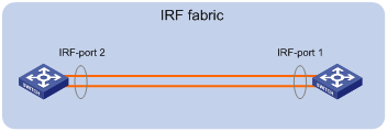
When you connect two neighboring IRF members, connect the physical interfaces of IRF-port 1 on one member to the physical interfaces of IRF-port 2 on the other (see Figure 10).
When you connect transceiver modules, connect the transmit port of the transceiver module at one end to the receive port of the transceiver module at the other end.
|
|
IMPORTANT: No intermediate devices are allowed between neighboring members. |
Figure 10 Connecting IRF physical interfaces
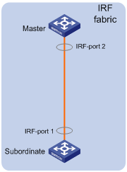
Connect the devices into a daisy-chain topology.
Figure 11 IRF daisy-chain topology
Setting the operating mode to IRF mode
By default, the device operates in standalone mode. To assign the device to an IRF fabric, you must change its operating mode to IRF mode.
To set the operating mode of a device to IRF mode:
|
Step |
Command |
Remarks |
|
1. (Optional.) Verify that a unique IRF member ID has been assigned to the device. |
display irf configuration |
Check the MemberID field. If the device does not have an IRF member ID, the field displays two hyphens (--). |
|
2. Enter system view. |
system-view |
N/A |
|
3. Set the operating mode to IRF mode. |
chassis convert mode irf |
The default operating mode is standalone mode. |
After you change the operating mode, the device automatically reboots for the change to take effect.
During the reboot, you may choose to have the system automatically convert the startup configuration file. Automatic configuration conversion prevents slot- or interface-related settings from becoming invalid. For example, the system can convert the slot slot-number parameter set in standalone mode to the chassis chassis-number slot slot-number parameter in IRF mode. The system can also add the chassis ID in an interface number.
To restore the standalone mode, use the undo chassis convert mode command.
|
|
TIP: IRF generates packets on a device in IRF mode even if the device does not form an IRF fabric with any other devices. To conserve system resources, set a device to standalone mode after removing it from an IRF fabric. |
Accessing the IRF fabric
The IRF fabric appears as one device after it is formed. You configure and manage all IRF members at the CLI of the global active MPU. All settings you made are automatically propagated to the IRF members.
When you log in to an IRF fabric, you are placed at the CLI of the global active MPU, regardless of at which member device you are logged in.
The following methods are available for accessing an IRF fabric:
· Local login—Log in through the console port of a member device.
· Remote login—Log in at a Layer 3 Ethernet interface on any member device by using methods including Telnet and SNMP.
For more information, see login configuration in Fundamentals Configuration Guide.
Configuring IRF member devices in IRF mode
After you access the global active MPU's CLI, you can perform the tasks in this section or configure features in all other configuration guides for the device.
Assigning an IRF domain ID to the IRF fabric
One IRF fabric forms one IRF domain. IRF domain IDs prevent IRF fabrics from interfering with one another.
To assign a domain ID to an IRF fabric:
|
Step |
Command |
Remarks |
|
1. Enter system view. |
system-view |
N/A |
|
2. Assign a domain ID to the IRF fabric. |
irf domain domain-id |
By default, the domain ID of an IRF fabric is 0. |
Changing the member ID of a device
|
|
CAUTION: · In IRF mode, an IRF member ID change can invalidate member ID-related settings and cause data loss. Make sure you fully understand its impact on your live network. · If you are exchanging the member IDs of member devices, you must place the member devices in standalone mode before renumbering them for a successful IRF merge. |
The new member ID takes effect at reboot. After the device reboots, the settings on all member ID related physical resources (including common physical network ports) are removed, regardless of whether you have saved the configuration.
To change the member ID of a member device:
|
Step |
Command |
Remarks |
|
1. Enter system view. |
system-view |
N/A |
|
2. Change the member ID of a member device. |
irf member member-id renumber new-member-id |
N/A |
|
3. Save the running configuration. |
save [ safely ] [ force ] |
N/A |
|
4. Reboot the member device. |
reboot chassis chassis-number |
The chassis-number must be the same as the member-id specified in the irf member member-id renumber new-member-id command. |
Changing the priority of a member device
You can change the priority of a member device so it can be elected the master at the next master election.
A change to member priority can affect the master re-election result. However, it does not cause an immediate master re-election.
To change the priority of a member device:
|
Step |
Command |
Remarks |
|
1. Enter system view. |
system-view |
N/A |
|
2. Specify a priority for a member of an IRF fabric. |
irf member member-id priority priority |
The default IRF member priority is 1. |
Adding physical interfaces to an IRF port
An IRF port can have a maximum of eight physical interfaces.
In IRF mode, you can add physical interfaces to an IRF port without traffic interruption on the IRF port.
When you perform this task, follow the IRF physical interface restrictions and configuration guidelines in the following sections:
· IRF physical interface restrictions.
· Binding physical interfaces to IRF ports.
To add physical interfaces to IRF ports:
|
Step |
Command |
Remarks |
|
1. Enter system view. |
system-view |
N/A |
|
2. Enter Ethernet interface view or interface range view. |
· Enter interface range view: · Enter interface view: |
To shut down a range of IRF physical interfaces, enter interface range view. To shut down one IRF physical interface, enter its interface view. |
|
3. Shut down the physical interfaces. |
shutdown |
If you have connected two peer IRF physical interfaces, shut down both interfaces before assigning them to their respective IRF ports. Failure to do so might cause IRF split. If the system does not allow you to shut down a physical interface, follow the system instruction to shut down its remote peer interface. |
|
4. Return to system view. |
quit |
N/A |
|
5. Enter IRF port view. |
irf-port member-id/port-number |
N/A |
|
6. Bind each physical interface to the IRF port. |
port group [ mdc mdc-id ] interface interface-type interface-number [ mode enhanced ] |
By default, no physical interfaces are bound to any IRF port. Repeat this step to assign multiple physical interfaces to the IRF port. You can bind a maximum of eight physical interfaces to an IRF port. An IRF physical interface operates in enhanced mode after the IRF binding takes effect, regardless of whether you have specified the mode enhanced keywords. |
|
7. Return to system view. |
quit |
N/A |
|
8. Enter Ethernet interface view or interface range view. |
· Enter interface range view: · Enter interface view: |
N/A |
|
9. Bring up the physical interfaces. |
undo shutdown |
N/A |
|
10. Return to system view. |
quit |
N/A |
|
11. Save the running configuration. |
save |
Activating IRF port settings causes IRF merge and reboot. To avoid data loss, save the running configuration to the startup configuration file before you perform the operation. |
|
12. Activate the configuration on the IRF port. |
irf-port-configuration active |
After this step is performed, the state of the IRF port changes to UP, the member devices elect a master, and the subordinate device reboots automatically. After the IRF fabric is formed, you can add additional physical interfaces to an IRF port (in UP state) without repeating this step. |
Enabling IRF auto-merge
When two IRF fabrics merge, you must reboot the member devices in the IRF fabric that fails in the master election. The auto-merge feature enables the IRF fabric to automatically reboot all its member devices to complete the merge.
This feature works only when it is enabled on both IRF fabrics that are merging.
To enable IRF auto-merge:
|
Step |
Command |
Remarks |
|
1. Enter system view. |
system-view |
N/A |
|
2. Enable IRF auto-merge. |
irf auto-merge enable |
By default, IRF auto-merge is enabled. |
Configuring a member device description
|
Step |
Command |
Remarks |
|
1. Enter system view. |
system-view |
N/A |
|
2. Configure a description for a member device. |
irf member member-id description text |
By default, no member device description is configured. |
Configuring IRF link load sharing mode
On an IRF port, traffic is balanced across its physical links.
You can configure the IRF port to distribute traffic based on any combination of the following criteria:
· IP addresses.
· MAC addresses.
· Incoming ports.
The system displays an error message if a criteria combination is not supported.
Configure the IRF link load sharing mode for IRF links in system view or IRF port view:
· In system view, the configuration is global and takes effect on all IRF ports.
· In IRF port view, the configuration is port specific and takes effect only on the specified IRF port.
An IRF port preferentially uses the port-specific load sharing mode. If no port-specific load sharing mode is available, the IRF port uses the global load sharing mode.
Configuring the global load sharing mode
|
Step |
Command |
Remarks |
|
1. Enter system view. |
system-view |
N/A |
|
2. Configure the global IRF link load sharing mode. |
irf-port global load-sharing mode { destination-ip | destination-mac | ingress-port | source-ip | source-mac } * |
The following are the default load sharing mode: · Non-IP traffic—Source and destination MAC addresses. · Non-TCP/-UDP IP traffic—Source and destination IP addresses. · TCP/UDP IP traffic—Source and destination service ports. If you execute this command multiple times, the most recent configuration takes effect. |
Configuring a port-specific load sharing mode
Before you configure a port-specific load sharing mode, make sure you have bound a minimum of one physical interface to the IRF port.
To configure a port-specific load sharing mode for an IRF port:
|
Step |
Command |
Remarks |
|
1. Enter system view. |
system-view |
N/A |
|
2. Enter IRF port view. |
irf-port member-id/port-number |
N/A |
|
3. Configure the port-specific load sharing mode. |
irf-port load-sharing mode { destination-ip | destination-mac | ingress-port | source-ip | source-mac } * |
By default, the global IRF link load sharing mode applies. If you execute this command multiple times, the most recent configuration takes effect. |
Configuring the IRF bridge MAC address
|
|
IMPORTANT: · This feature is available in Release 2138P01 and later versions. · Use this feature with caution. The bridge MAC address change causes transient traffic disruption. |
Use this feature to configure the bridge MAC address of an IRF fabric. Layer 2 protocols, such as LACP, use the IRF bridge MAC address to identify an IRF fabric. On a switched LAN, the bridge MAC address must be unique.
When IRF fabrics merge, IRF ignores the configured IRF bridge MAC address and only checks the bridge MAC address of each member device in the IRF fabrics. IRF merge fails if any of the member devices have the same bridge MAC address.
After IRF fabrics merge, the merged IRF fabric uses the bridge MAC address of the merging IRF fabric whose master has the higher priority as the IRF bridge MAC address.
If an IRF fabric splits after you configure the IRF bridge MAC address, both the split IRF fabrics use the configured bridge MAC address as the IRF bridge MAC address.
To configure the IRF bridge MAC address:
|
Step |
Command |
Remarks |
|
1. Enter system view. |
system-view |
N/A |
|
2. Configure the IRF bridge MAC address. |
irf mac-address mac-address |
By default, an IRF fabric uses the bridge MAC address of the master as the IRF bridge MAC address. |
Configuring IRF bridge MAC persistence
|
|
IMPORTANT: · This feature does not take effect if the IRF bridge MAC address is configured by using the irf mac-address mac-address command. · The IRF bridge MAC address change causes transient traffic disruption. |
Depending on the network condition, enable the IRF fabric to retain or change its bridge MAC address after the address owner leaves. Available options include:
· irf mac-address persistent always—Bridge MAC address of the IRF fabric does not change after the address owner leaves.
· undo irf mac-address persistent—Bridge MAC address of the current master replaces the original bridge MAC address as soon as the owner of the original address leaves.
IRF fabrics cannot merge if they contain member devices that have the same bridge MAC address.
To configure the IRF bridge MAC persistence setting:
|
Step |
Command |
Remarks |
|
1. Enter system view. |
system-view |
N/A |
|
2. Configure IRF bridge MAC persistence. |
· Retain the bridge MAC address permanently even if the address owner has left the fabric: · Change the bridge MAC address as soon as the address owner leaves the fabric: |
By default, the IRF bridge MAC address is retained permanently even if the address owner has left the fabric. |
Enabling software auto-update for system software image synchronization
|
|
IMPORTANT: To ensure a successful software auto-update in a multi-user environment, prevent anyone from swapping or rebooting the MPUs or member devices during the auto-update process. To inform administrators of the auto-update status, configure the information center to output the status messages to configuration terminals (see Network Management and Monitoring Configuration Guide). |
The software auto-update feature automatically propagates the software images of the global active MPU to all other MPUs in the IRF fabric.
To join an IRF fabric, an MPU must use the same software images as the global active MPU in the fabric.
When you add an MPU to the IRF fabric, software auto-update compares the startup software images of the MPU with the current software images of the IRF global active MPU. If the two sets of images are different, the MPU automatically performs the following operations:
1. Downloads the current software images of the global active MPU.
2. Sets the downloaded images as the main startup software images.
3. Reboots with the new software images to rejoin the IRF fabric.
You must manually update the new device or MPU with the software images running on the IRF fabric in the following situations:
· Software auto-update is disabled.
· Software auto-update fails to update software. This situation might occur if the IRF fabric cannot identify the software version used on the new device or MPU.
|
|
NOTE: To synchronize software from the active MPU to the standby MPU in standalone mode, use the undo version check ignore and version auto-update enable commands. For more information about these commands, see Fundamentals Configuration Guide. |
Configuration prerequisites
Make sure the MPU you are adding to the IRF fabric has sufficient storage space for the new software images.
If sufficient storage space is not available, the device deletes the current software images automatically. If the reclaimed space is still insufficient, the MPU cannot complete the auto-update. You must reboot the MPU, and then access the BootWare menus to delete files.
Configuration procedure
To enable software auto-update:
|
Step |
Command |
Remarks |
|
1. Enter system view. |
system-view |
N/A |
|
2. Enable software auto-update. |
irf auto-update enable |
By default, software auto-update is enabled. |
Setting the IRF link down report delay
To prevent frequent IRF splits and merges during link flapping, configure the IRF ports to delay reporting link down events.
An IRF port does not report a link down event to the IRF fabric immediately after its link changes from up to down. If the IRF link state is still down when the delay is reached, the port reports the change to the IRF fabric.
IRF ports do not delay link up events. They report the link up event immediately after the IRF link comes up.
When you configure the IRF link down report delay, follow these restrictions and guidelines:
· Make sure the IRF link down report delay is shorter than the heartbeat or hello timeout settings of upper-layer protocols (for example, VRRP and OSPF). If the report delay is longer than the timeout setting of a protocol, unnecessary recalculations might occur.
· Set the delay to 0 seconds in the following situations:
? The IRF fabric requires a fast master/subordinate or IRF link switchover.
? The BFD or GR feature is used.
To set the IRF link down report delay:
|
Step |
Command |
Remarks |
|
1. Enter system view. |
system-view |
N/A |
|
2. Set the IRF link down report delay. |
irf link-delay interval |
The default IRF link down report delay is 4000 milliseconds (4 seconds). |
Configuring MAD
The following MAD mechanisms are available for detecting multi-active collisions in different network scenarios:
· LACP MAD.
· BFD MAD.
LACP MAD handles collisions differently than BFD MAD. To avoid conflicts, do not enable LACP MAD together with BFD MAD in an IRF fabric.
Table 2 provides a reference for you to make a MAD mechanism selection decision.
Table 2 Comparison of MAD mechanisms
|
MAD mechanism |
Advantages |
Disadvantages |
Application scenario |
|
LACP MAD |
· Detection speed is fast. · Does not require MAD-dedicated physical links or Layer 3 interfaces. |
Requires an intermediate H3C device that supports extended LACPDUs for MAD. |
Link aggregation is used between the IRF fabric and its upstream or downstream device. For information about LACP, see Layer 2—LAN Switching Configuration Guide. |
|
BFD MAD |
· Detection speed is fast. · No intermediate device is required. · Intermediate device, if used, can come from any vendor. |
· Requires MAD dedicated physical links and Layer 3 interfaces, which cannot be used for transmitting user traffic. · If no intermediate device is used, any two IRF members must have a BFD MAD link to each other. · If an intermediate device is used, every IRF member must have a BFD MAD link to the intermediate device. |
· No special requirements for network scenarios. · If no intermediate device is used, this mechanism is only suitable for IRF fabrics that have a small number of members that are geographically close to one another. For information about BFD, see High Availability Configuration Guide. |
Configuring LACP MAD
When you use LACP MAD, follow these guidelines:
· The intermediate device must be an H3C device that support extended LACP for MAD.
· If the intermediate device is also an IRF fabric, you must assign the two IRF fabrics different domain IDs for correct split detection.
· Use dynamic link aggregation mode. MAD is LACP dependent. Even though LACP MAD can be configured on both static and dynamic aggregate interfaces, it takes effect only on dynamic aggregate interfaces.
· Configure link aggregation settings also on the intermediate device.
To configure LACP MAD:
|
Step |
Command |
Remarks |
|
1. Enter system view. |
system-view |
N/A |
|
2. (Optional.) Assign a domain ID to the IRF fabric. |
irf domain domain-id |
The default IRF domain ID is 0. |
|
3. Create a Layer 2 aggregate interface and enter aggregate interface view. |
interface bridge-aggregation interface-number |
Perform this step also on the intermediate device. |
|
4. Configure the aggregation group to operate in dynamic aggregation mode. |
link-aggregation mode dynamic |
By default, an aggregation group operates in static aggregation mode. Perform this step also on the intermediate device. |
|
5. Enable LACP MAD. |
mad enable |
By default, LACP MAD is disabled. |
|
6. Return to system view. |
quit |
N/A |
|
7. Enter Ethernet interface view or interface range view. |
· Enter interface range view: ? Method 1: ? Method 2: · Enter Ethernet interface view: |
To assign a range of ports to the aggregation group, enter interface range view. To assign one port to the aggregation group, enter Ethernet interface view. |
|
8. Assign the Ethernet port or the range of Ethernet ports to the specified aggregation group. |
port link-aggregation group number |
Multichassis link aggregation is allowed. Perform this step also on the intermediate device. |
Configuring BFD MAD that uses common Ethernet ports
Configure BFD MAD on a VLAN interface if you use common Ethernet ports for BFD MAD.
When you configure BFD MAD settings, follow these restrictions and guidelines:
|
Category |
Restrictions and guidelines |
|
BFD MAD VLAN |
· Do not enable BFD MAD on VLAN-interface 1. · If you are using an intermediate device, perform the following tasks on both the IRF fabric and intermediate device: ? Create a VLAN and VLAN interface for BFD MAD. ? Assign the ports of BFD MAD links to the BFD MAD VLAN. · Make sure the IRF fabrics on the network use different BFD MAD VLANs. |
|
BFD MAD VLAN and feature compatibility |
· Do not use the BFD MAD VLAN for any purpose other than configuring BFD MAD. Layer 2 or Layer 3 features, including ARP and LACP, cannot work on the BFD MAD-enabled VLAN interface or any port in the VLAN. If you configure any other feature on the VLAN, neither the configured feature nor the BFD MAD feature will work correctly. · Disable the spanning tree feature on any Layer 2 Ethernet ports in the BFD MAD VLAN. The MAD feature is mutually exclusive with the spanning tree feature. |
|
IRF domain ID |
If the intermediate device is also an IRF fabric, you must assign the two IRF fabrics different domain IDs for correct split detection. |
|
MAD IP address |
· To avoid problems, only use the mad ip address command to configure IP addresses on the BFD MAD-enabled VLAN interface. Do not configure an IP address with the ip address command or configure a VRRP virtual address on the BFD MAD-enabled VLAN interface. · Make sure all the MAD IP addresses are on the same subnet. · The MAD IP addresses must not be the same as any IP addresses assigned to interfaces or VRRP groups in the IRF fabric. |
To configure BFD MAD that uses common Ethernet ports:
|
Step |
Command |
Remarks |
|
1. Enter system view. |
system-view |
N/A |
|
2. (Optional.) Assign a domain ID to the IRF fabric. |
irf domain domain-id |
By default, the domain ID of an IRF fabric is 0. |
|
3. Create a new VLAN dedicated to BFD MAD. |
vlan vlan-id |
The default VLAN on the device is VLAN 1. |
|
4. Return to system view. |
quit |
N/A |
|
5. Enter Ethernet interface view or interface range view. |
· Enter interface range view: ? Method 1: ? Method 2: · Enter Ethernet interface view: |
To assign a range of ports to the BFD MAD VLAN, enter interface range view. To assign one port to the BFD MAD VLAN, enter Ethernet interface view. |
|
6. Assign the port or the range of ports to the BFD MAD VLAN. |
· Assign the port to the VLAN as an access port: · Assign the port to the VLAN as a trunk port: · Assign the port to the VLAN as a hybrid port: |
The link type of BFD MAD ports can be access, trunk, or hybrid. The default link type of a port is access. |
|
7. Return to system view. |
quit |
N/A |
|
8. Enter VLAN interface view. |
interface vlan-interface interface-number |
N/A |
|
9. Enable BFD MAD. |
mad bfd enable |
By default, BFD MAD is disabled. |
|
10. Configure a MAD IP address for a member on the VLAN interface. |
mad ip address ip-address { mask | mask-length } member member-id |
By default, no MAD IP address is configured on any VLAN interface. Repeat this step to assign a MAD IP address to each member device on the VLAN interface. The MAD IP addresses identify the member devices and must belong to the same subnet. |
Configuring BFD MAD that uses management Ethernet ports
|
|
IMPORTANT: This feature is available in Release 2138P01 and later versions. |
When you configure BFD MAD that uses management Ethernet ports, follow these restrictions and guidelines:
|
Category |
Restrictions and guidelines |
|
Ports on the intermediate device for BFD MAD |
Use common Ethernet ports on the intermediate device to connect the management Ethernet ports on the IRF fabric. |
|
BFD MAD VLAN |
· On the intermediate device, create a VLAN for BFD MAD, and assign the ports used for BFD MAD to the VLAN. On the IRF fabric, you do not need to assign the management Ethernet ports to the VLAN. · Make sure the IRF fabrics on the network use different BFD MAD VLANs. |
|
IRF domain ID |
If the intermediate device is also an IRF fabric, you must assign the two IRF fabrics different domain IDs for correct split detection. |
|
MAD IP address |
· To avoid problems, only use the mad ip address command to configure IP addresses on the BFD MAD-enabled management Ethernet port. Do not configure an IP address with the ip address command or configure a VRRP virtual address on the BFD MAD-enabled management Ethernet port. · Make sure all the MAD IP addresses are on the same subnet. · The MAD IP addresses must not be the same as any IP addresses assigned to interfaces or VRRP groups in the IRF fabric. |
To configure BFD MAD that uses management Ethernet ports:
|
Step |
Command |
Remarks |
|
1. Enter system view. |
system-view |
N/A |
|
2. (Optional.) Assign a domain ID to the IRF fabric. |
irf domain domain-id |
By default, the domain ID of an IRF fabric is 0. |
|
3. Enter management Ethernet interface view. |
interface m-gigabitethernet interface-number |
Of all management Ethernet ports on an IRF fabric, only the master's management Ethernet port is accessible. |
|
4. Enable BFD MAD. |
mad bfd enable |
By default, BFD MAD is disabled. |
|
5. Assign a MAD IP address to each member device. |
mad ip address ip-address { mask | mask-length } member member-id |
By default, no MAD IP addresses are configured. |
Excluding a port from the shutdown action upon detection of multi-active collision
|
|
CAUTION: Excluding a VLAN interface and its Layer 2 ports from the shutdown action introduces IP collision risks because the VLAN interface might be active on both the active and inactive IRF fabrics. |
By default, all ports except the console and IRF physical interfaces shut down automatically when the IRF fabric transits to the Recovery state.
You can exclude a port from the shutdown action for management or other special purposes. For example:
· Exclude a port from the shutdown action, so you can Telnet to the port for managing the device.
· Exclude a VLAN interface and its Layer 2 ports from the shutdown action, so you can log in through the VLAN interface.
To configure a port to not shut down when the IRF fabric transits to the Recovery state:
|
Step |
Command |
Remarks |
|
1. Enter system view. |
system-view |
N/A |
|
2. Configure a port to not shut down when the IRF fabric transits to the Recovery state. |
mad exclude interface interface-type interface-number |
By default, all network ports on a Recovery-state IRF fabric are shut down, except for the IRF physical interfaces and console port. |
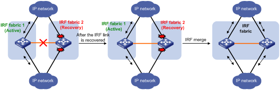
Recovering an IRF fabric
After the failed IRF link between two split IRF fabrics is recovered, log in to the Recovery-state IRF fabric, and use the reboot command to reboot all its members. If the irf auto-merge enable command has been configured, the inactive IRF member devices automatically reboot after the failed link is recovered. After these member devices join the active IRF fabric as subordinates, IRF merge is complete, as shown in Figure 12.
Figure 12 Recovering the IRF fabric
If the active IRF fabric fails before the IRF link is recovered (see Figure 13), use the mad restore command on the inactive IRF fabric to recover the inactive IRF fabric. The command also brings up all physical interfaces that were shut down by MAD. After you repair the IRF link, the two parts merge into a unified IRF fabric.
Figure 13 Active IRF fabric fails before the IRF link is recovered
To manually recover an inactive IRF fabric:
|
Step |
Command |
|
1. Enter system view. |
system-view |
|
2. Recover the inactive IRF fabric. |
mad restore |
After the IRF fabric is recovered, all ports that have been shut down by MAD come up automatically.
Displaying and maintaining an IRF fabric
Execute display commands in any view.
|
Task |
Command |
|
Display information about all IRF members. |
display irf |
|
Display the IRF fabric topology. |
display irf topology |
|
Display IRF link information. |
display irf link |
|
Display basic IRF settings. |
display irf configuration |
|
Display the load sharing mode for IRF links. |
display irf-port load-sharing mode [ irf-port [ member-id/port-number ] ] |
|
Display MAD configuration. |
display mad [ verbose ] |
Configuration examples
This section provides IRF configuration examples for two-chassis IRF fabrics that use different MAD mechanisms.
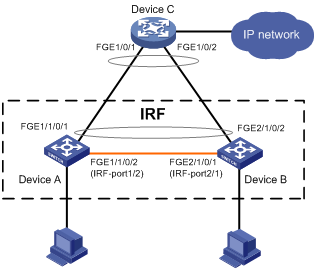
LACP MAD-enabled IRF configuration example
Network requirements
As shown in Figure 14, set up a two-chassis IRF fabric at the access layer of the enterprise network.
Configure LACP MAD on the multichassis aggregation to Device C, an H3C device that supports extended LACP.
Configuration procedure
|
|
IMPORTANT: Between two neighboring IRF members, IRF links must be bound to IRF-port 1 on one member and to IRF-port 2 on the other. |
1. Configure Device A:
# Assign member ID 1 to Device A, and bind FortyGigE 1/0/2 to IRF-port 2.
<Sysname> system-view
[Sysname] irf member 1
Info: Member ID change will take effect after the member reboots and operates in IRF mode.
[Sysname] irf-port 2
[Sysname-irf-port2] port group interface fortygige 1/0/2
[Sysname-irf-port2] quit
# Save the configuration.
[Sysname] quit
<Sysname> save
# Enable IRF mode.
<Sysname> system-view
[Sysname] chassis convert mode irf
The device will switch to IRF mode and reboot. You are recommended to save the current running configuration and specify the configuration file for the next startup. Continue? [Y/N]:y
Do you want to convert the content of the next startup configuration file flash:/startup.cfg to make it available in IRF mode? [Y/N]:y
Please wait...
Saving the converted configuration file to the main board succeeded.
Slot 1:
Saving the converted configuration file succeeded.
Now rebooting, please wait...
Device A reboots to form a single-chassis IRF fabric.
2. Configure Device B:
# Assign member ID 2 to Device B, and bind FortyGigE 1/0/1 to IRF-port 1.
<Sysname> system-view
[Sysname] irf member 2
Info: Member ID change will take effect after the member reboots and operates in IRF mode.
[Sysname] irf-port 1
[Sysname-irf-port1] port group interface fortygige 1/0/1
[Sysname-irf-port1] quit
# Save the configuration.
[Sysname] quit
<Sysname> save
# Connect the two devices as shown in Figure 14.
# Log in to Device B. (Details not shown.)
# Enable IRF mode.
<Sysname> system-view
[Sysname] chassis convert mode irf
The device will switch to IRF mode and reboot. You are recommended to save the current running configuration and specify the configuration file for the next startup. Continue? [Y/N]:y
Do you want to convert the content of the next startup configuration file flash:/startup.cfg to make it available in IRF mode? [Y/N]:y
Please wait...
Saving the converted configuration file to the main board succeeded.
Slot 1:
Saving the converted configuration file succeeded.
Now rebooting, please wait...
Device B and Device A form a two-chassis IRF fabric after Device B reboots.
3. Configure LACP MAD:
# Assign domain ID 1 to the IRF fabric.
<Sysname> system-view
[Sysname] irf domain 1
# Create a dynamic aggregate interface and enable LACP MAD.
[Sysname] interface bridge-aggregation 2
[Sysname-Bridge-Aggregation2] link-aggregation mode dynamic
[Sysname-Bridge-Aggregation2] mad enable
You need to assign a domain ID (range: 0-4294967295)
[Current domain is: 1]:
The assigned domain ID is: 1
MAD LACP only enable on dynamic aggregation interface.
[Sysname-Bridge-Aggregation2] quit
# Assign FortyGigE 1/1/0/1 and FortyGigE 2/1/0/2 to the aggregate interface.
[Sysname] interface fortygige 1/1/0/1
[Sysname-FortyGigE1/1/0/1] port link-aggregation group 2
[Sysname-FortyGigE1/1/0/1] quit
[Sysname] interface fortygige 2/1/0/2
[Sysname-FortyGigE2/1/0/2] port link-aggregation group 2
[Sysname-FortyGigE2/1/0/2] quit
4. Configure Device C as the intermediate device:
|
|
CAUTION: If the intermediate device is also an IRF fabric, assign the two IRF fabrics different domain IDs for correct split detection. False detection causes IRF split. |
# Create a dynamic aggregate interface.
<Sysname> system-view
[Sysname] interface bridge-aggregation 2
[Sysname-Bridge-Aggregation2] link-aggregation mode dynamic
[Sysname-Bridge-Aggregation2] quit
# Assign FortyGigE 1/0/1 and FortyGigE 1/0/2 to the aggregate interface.
[Sysname] interface fortygige 1/0/1
[Sysname-FortyGigE1/0/1] port link-aggregation group 2
[Sysname-FortyGigE1/0/1] quit
[Sysname] interface fortygige 1/0/2
[Sysname-FortyGigE1/0/2] port link-aggregation group 2
[Sysname-FortyGigE1/0/2] quit
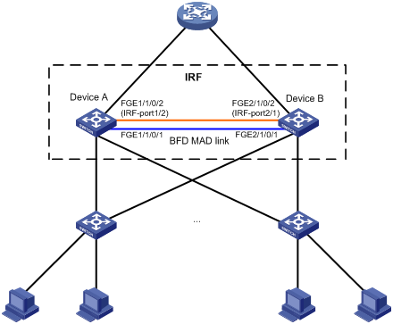
BFD MAD-enabled IRF configuration example
Network requirements
As shown in Figure 15, set up an IRF fabric at the distribution layer of the network.
· Configure BFD MAD in the IRF fabric and set up BFD MAD links between the member devices.
· Disable the spanning tree feature on the ports used for BFD MAD, because the two features conflict with each other.
Configuration procedure
1. Configure IRF on Device A:
# Assign member ID 1 to Device A.
<Sysname> system-view
[Sysname] irf member 1
Info: Member ID change will take effect after the member reboots and operates in IRF mode.
# Enable IRF mode.
[Sysname] chassis convert mode irf
The device will switch to IRF mode and reboot. You are recommended to save the current running configuration and specify the configuration file for the next startup. Continue? [Y/N]:y
Do you want to convert the content of the next startup configuration file flash:/startup.cfg to make it available in IRF mode? [Y/N]:y
Please wait...
Saving the converted configuration file to the main board succeeded.
Slot 1:
Saving the converted configuration file succeeded.
Now rebooting, please wait...
Device A reboots to form a single-chassis IRF fabric.
# Bind FortyGigE 1/1/0/2 to IRF-port 1/2.
<Sysname> system-view
[Sysname] interface fortygige 1/1/0/2
[Sysname-FortyGigE1/1/0/2] shutdown
[Sysname-FortyGigE1/1/0/2] quit
[Sysname] irf-port 1/2
[Sysname-irf-port1/2] port group interface fortygige 1/1/0/2
[Sysname-irf-port1/2] quit
[Sysname] interface fortygige 1/1/0/2
[Sysname-FortyGigE1/1/0/2] undo shutdown
[Sysname-FortyGigE1/1/0/2] quit
# Save the running configuration to the startup configuration file.
[Sysname] quit
<Sysname> save
2. Configure IRF on Device B:
# Assign member ID 2 to Device B.
<Sysname> system-view
[Sysname] irf member 2
Info: Member ID change will take effect after the member reboots and operates in IRF mode.
# Enable IRF mode.
[Sysname] chassis convert mode irf
The device will switch to IRF mode and reboot. You are recommended to save the current running configuration and specify the configuration file for the next startup. Continue? [Y/N]:y
Do you want to convert the content of the next startup configuration file flash:/startup.cfg to make it available in IRF mode? [Y/N]:y
Please wait...
Saving the converted configuration file to the main board succeeded.
Slot 1:
Saving the converted configuration file succeeded.
Now rebooting, please wait...
Device B reboots to form a single-chassis IRF fabric.
# Bind FortyGigE 2/1/0/2 to IRF-port 2/1.
<Sysname> system-view
[Sysname] interface fortygige 2/1/0/2
[Sysname-FortyGigE2/1/0/2] shutdown
[Sysname-FortyGigE2/1/0/2] quit
[Sysname] irf-port 2/1
[Sysname-irf-port2/1] port group interface fortygige 2/1/0/2
[Sysname-irf-port2/1] quit
[Sysname] interface fortygige 2/1/0/2
[Sysname-FortyGigE2/1/0/2] undo shutdown
[Sysname-FortyGigE2/1/0/2] quit
# Save the running configuration to startup configuration file.
[Sysname] quit
<Sysname> save
3. Activate the configuration on IRF ports:
# Connect Device B to Device A as shown in Figure 15.
# Log in to Device A. (Details not shown.)
# Activate IRF port configuration on Device A.
<Sysname> system-view
[Sysname] irf-port-configuration active
# Log in to Device B. (Details not shown.)
# Activate IRF port configuration on Device B.
<Sysname> system-view
[Sysname] irf-port-configuration active
%Jul 9 09:04:48:279 2013 STM/4/STM_MERGE_NEED_REBOOT: IRF merge occurs and the IRF system needs a reboot.
%Jul 9 14:03:06:855 2013 STM/5/STM_MERGE: IRF merge occurs and the IRF system does not need to reboot.
# Reboot Device B.
[Sysname] quit
<Sysname> reboot
Device A and Device B form a two-chassis IRF fabric after Device B reboots. Device B is the subordinate device.
4. Configure BFD MAD:
# Create VLAN 3, and add FortyGigE 1/1/0/1 and FortyGigE 2/1/0/1 to VLAN 3.
<Sysname> system-view
[Sysname] vlan 3
[Sysname-vlan3] port fortygige 1/1/0/1 fortygige 2/1/0/1
[Sysname-vlan3] quit
# Create VLAN-interface 3, and configure a MAD IP address for each member device on the VLAN interface.
[Sysname] interface vlan-interface 3
[Sysname-Vlan-interface3] mad bfd enable
[Sysname-Vlan-interface3] mad ip address 192.168.2.1 24 member 1
[Sysname-Vlan-interface3] mad ip address 192.168.2.2 24 member 2
[Sysname-Vlan-interface3] quit
# Disable the spanning tree feature on FortyGigE 1/1/0/1 and FortyGigE 2/1/0/1.
[Sysname] interface fortygige 1/1/0/1
[Sysname-FortyGigE1/1/0/1] undo stp enable
[Sysname-FortyGigE1/1/0/1] quit
[Sysname] interface fortygige 2/1/0/1
[Sysname-FortyGigE2/1/0/1] undo stp enable
[Sysname-FortyGigE2/1/0/1] quit
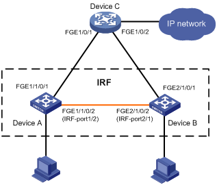
Configuration example for restoring standalone mode
Network requirements
Break the IRF fabric in Figure 16, and change the operating mode of Device A and Device B from IRF to standalone.
Configuration procedure
1. Identify the master.
<IRF> display irf
MemberID Slot Role Priority CPU-Mac Description
*+1 0 Master 1 00e0-fc0a-15e0 DeviceA
1 1 Standby 1 00e0-fc0f-8c02 DeviceA
2 0 Standby 1 00e0-fc0f-15e1 DeviceB
2 1 Standby 1 00e0-fc0f-15e2 DeviceB
--------------------------------------------------
* indicates the device is the master.
+ indicates the device through which the user logs in.
The Bridge MAC of the IRF is: 000f-e26a-58ed
Auto upgrade : no
Mac persistent : always
Domain ID : 0
The output shows that Device A is the master.
2. Examine the configuration for VLAN interfaces.
If a VLAN interface has member ports on different member devices, change the IP address for the interface on each device to be unique.
3. Shut down IRF physical interfaces to disconnect all IRF links. In this example, shut down FortyGigE 1/1/0/2.
<IRF> system-view
[IRF] interface fortygige 1/1/0/2
[IRF-FortyGigE1/1/0/2] shutdown
[IRF-FortyGigE1/1/0/2] quit
4. Save the configuration.
[IRF] save
The current configuration will be written to the device. Are you sure? [Y/N]:y
Please input the file name(*.cfg)[flash:/startup.cfg]
(To leave the existing filename unchanged, press the enter key):
flash:/startup.cfg exists, overwrite? [Y/N]:y
Validating file. Please wait.....................................
The current configuration is saved to the active main board successfully.
Configuration is saved to device successfully.
5. Change the operating mode of Device A to standalone.
[IRF] undo chassis convert mode
The device will switch to stand-alone mode and reboot. You are recommended to save the current running configuration and specify the configuration file for the next startup. Continue? [Y/N]:y
Do you want to convert the content of the next startup configuration file flash:/startup.cfg to make it available in stand-alone mode? [Y/N]:y
Please wait.............
Saving the converted configuration file to main board succeeded.
Chassis 1 Slot 1:
Saving the converted configuration file succeeded.
Now rebooting, please wait...
Device A automatically reboots to complete the operating mode change.
6. Log in to Device B and change its operating mode to standalone.
<IRF> system-view
[IRF] undo chassis convert mode
The device will switch to stand-alone mode and reboot. You are recommended to save the current running configuration and specify the configuration file for the next startup. Continue? [Y/N]:y
Do you want to convert the content of the next startup configuration file flash:/startup.cfg to make it available in stand-alone mode? [Y/N]:y
Please wait.............
Saving the converted configuration file to main board succeeded.
Chassis 2 Slot 1:
Saving the converted configuration file succeeded.
Now rebooting, please wait...
Device B automatically reboots to complete the operating mode change.
A
accessing
IRF fabric, 20
active
IRF active MPU, 5
adding
IRF physical interfaces (IRF mode), 21
application scenario
IRF, 1
IRF BFD MAD, 10
IRF LACP MAD, 9
assigning
IRF fabric domain ID (IRF mode), 20
IRF member device IDs (standalone mode), 16
auto
IRF auto-merge (IRF mode), 23
IRF software image synchronization auto-update (IRF mode), 26
B
BFD
MAD. See BFD MAD
IRF application scenario, 10
IRF BFD MAD configuration, 37
IRF BFD MAD configuration (Ethernet port/IRF mode), 29
IRF BFD MAD configuration (management Ethernet port/IRF mode), 31
binding
IRF physical interfaces to IRF ports (standalone mode), 17
bridge MAC address (IRF mode), 24
bridge MAC persistence (IRF mode), 25
C
changing
IRF device member ID (IRF mode), 20
IRF member priority (IRF mode), 21
CLI
IRF fabric access CLI login, 20
collision handling (IRF), 9
configuration
backup (IRF), 14
configuring
IRF, 12, 15
IRF BFD MAD, 37
IRF BFD MAD (Ethernet port/IRF mode), 29
IRF BFD MAD (management Ethernet port/IRF mode), 31
IRF bridge MAC address (IRF mode), 24
IRF bridge MAC persistence (IRF mode), 25
IRF fabric, 34
IRF LACP MAD, 34
IRF LACP MAD (IRF mode), 28
IRF link load sharing mode (global/IRF mode), 24
IRF link load sharing mode (IRF mode), 23
IRF load sharing mode (port-specific/IRF mode), 24
IRF MAD (IRF mode), 27
IRF member device (IRF mode), 20
IRF member device description (IRF mode), 23
connecting
IRF physical interfaces, 18
D
detecting
IRF BFD MAD, 10
IRF collision handling, 9
IRF failure recovery, 9
IRF LACP MAD, 9
IRF MAD, 8
IRF MAD handling procedure, 8
displaying
IRF fabric, 34
domain
IRF domain ID, 6
IRF fabric domain ID assignment (IRF mode), 20
E
ECMP
IRF ECMP route maximum number restrictions, 13
enabling
IRF auto-merge (IRF mode), 23
IRF software auto-update (IRF mode), 26
error
IRF connection error notification, 8
excluding
IRF port from shutdown action, 32
F
fabric
IRF application scenario, 1
IRF BFD MAD, 10
IRF BFD MAD configuration, 37
IRF bridge MAC address (IRF mode), 24
IRF bridge MAC persistence (IRF mode), 25
IRF collision handling, 9
IRF configuration, 12, 15, 34
IRF connection error notification, 8
IRF device member priority (standalone mode), 16
IRF domain ID, 6
IRF fabric access, 20
IRF fabric domain ID assignment (IRF mode), 20
IRF fabric recovery, 33
IRF failure recovery, 9
IRF LACP MAD, 9
IRF LACP MAD configuration, 34
IRF link load sharing mode (IRF mode), 23
IRF loop elimination mechanism, 8
IRF MAD, 8
IRF MAD detection, 9
IRF MAD handling procedure, 8
IRF member configuration (IRF mode), 20
IRF member device configuration (standalone mode), 16
IRF member device description (IRF mode), 23
IRF member device ID assignment (standalone mode), 16
IRF member ID, 5
IRF member priority, 7
IRF member roles, 4
IRF merge, 7
IRF network topologies, 2
IRF operating mode set, 19
IRF overview, 1
IRF physical interface, 6
IRF port, 5
IRF setup, 15
IRF software auto-update enable (IRF mode), 26
IRF split, 6
IRF standalone mode restoration, 40
failure
IRF failure recovery, 9
feature
IRF restrictions, 13
file
virtual technologies IRF next-startup configuration file save, 18
G
guidelines
multichassis link aggregation, 13
H
hardware
IRF hardware compatibility, 1
I
ID
IRF domain, 6
Intelligent Resilient Framework. Use IRF
application scenario, 1
auto-merge (IRF mode), 23
basic concepts, 2
BFD MAD, 10
BFD MAD configuration, 37
BFD MAD configuration (Ethernet port/IRF mode), 29
BFD MAD configuration (management Ethernet port/IRF mode), 31
bridge MAC address (IRF mode), 24
bridge MAC persistence (IRF mode), 25
configuration, 12, 15
configuration backup, 14
configuration restrictions, 12
connection error notification, 8
device member ID change (IRF mode), 20
device member priority (standalone mode), 16
displaying fabric, 34
domain ID, 6
domain restrictions, 14
ECMP route maximum number restrictions, 13
fabric access, 20
fabric configuration, 34
fabric domain ID assignment (IRF mode), 20
fabric recovery, 33
fabric setup, 15
feature restrictions, 13
hardware compatibility, 1
LACP MAD, 9
LACP MAD configuration, 34
LACP MAD configuration (IRF mode), 28
link down report delay (IRF mode), 27
link load sharing mode (global/IRF mode), 24
link load sharing mode (IRF mode), 23
link redundancy restrictions, 13
load sharing mode (port-specific/IRF mode), 24
loop elimination mechanism, 8
MAD, 8
MAD configuration (IRF mode), 27
MAD detection, 9
MAD handling procedure, 8
MAD restrictions, 14
master election, 7
MDC restrictions, 14
member device configuration (IRF mode), 20
member device configuration (standalone mode), 16
member device description (IRF mode), 23
member device ID assignment (standalone mode), 16
member ID, 5
member ID restrictions, 12
member priority, 7
member priority change (IRF mode), 21
member roles, 4
merge, 7
merge restrictions, 14
MPU restrictions, 12
MPU role, 5
multichassis link aggregation, 13
network topologies, 2
next-startup configuration file save, 18
operating mode set, 19
operating modes, 4
overview, 1
physical interface, 6
physical interface addition (IRF mode), 21
physical interface connection, 18
physical interface restrictions, 12
physical interface to IRF port bind (standalone mode), 17
port, 5
port connection restrictions, 13
port shutdown exclusion, 32
size restrictions, 12
software auto-update enable (IRF mode), 26
split, 6
standalone mode restoration, 40
system operation restrictions, 13
transceiver modules+cables restrictions, 12
L
LACP
MAD. See LACP MAD
IRF dynamic link aggregation group, 9
IRF LACP MAD configuration, 34
IRF LACP MAD configuration (IRF mode), 28
link
IRF collision handling, 9
IRF fabric recovery, 33
IRF failure recovery, 9
IRF link down report delay (IRF mode), 27
IRF link load sharing mode (IRF mode), 23
load sharing
IRF link load sharing mode (IRF mode), 23
IRF load sharing mode (port-specific/IRF mode), 24
IRF mode configuration (global/IRF mode), 24
local
IRF fabric access local login, 20
loop eliminating
IRF loop elimination mechanism, 8
M
MAC addressing
IRF bridge MAC address (IRF mode), 24
IRF bridge MAC persistence (IRF mode), 25
BFD. See BFD MAD
detection, 9
handling procedure, 8
IRF fabric recovery, 33
IRF fabric split, 8
IRF MAD configuration (IRF mode), 27
LACP. See LACP MAD
master
IRF master election, 7
IRF master MPU, 5
MDC
IRF restrictions, 14
member
IRF device configuration (standalone mode), 16
IRF device ID assignment (standalone mode), 16
IRF device member ID change (IRF mode), 20
IRF device member priority (standalone mode), 16
IRF fabric access, 20
IRF master election, 7
IRF member device description (IRF mode), 23
IRF member ID, 5
IRF member priority, 7
IRF member priority change (IRF mode), 21
IRF physical interface connection, 18
IRF roles, 4
physical interface to IRF port bind (standalone mode), 17
merging
IRF auto-merge (IRF mode), 23
IRF fabric merge, 7
IRF master election, 7
mode
IRF operating mode, 4
IRF operating mode set, 19
IRF standalone mode restoration, 40
IRF standalone operating mode, 4
MPU
IRF restrictions, 12
multi-active detection. Use MAD
N
network
IRF application scenario, 1
IRF BFD MAD, 10
IRF BFD MAD configuration (Ethernet port/IRF mode), 29
IRF BFD MAD configuration (management Ethernet port/IRF mode), 31
IRF connection error notification, 8
IRF domain ID, 6
IRF domain restrictions, 14
IRF fabric recovery, 33
IRF fabric setup, 15
IRF LACP MAD, 9
IRF LACP MAD configuration (IRF mode), 28
IRF link down report delay (IRF mode), 27
IRF loop elimination mechanism, 8
IRF MAD, 8
IRF MAD configuration (IRF mode), 27
IRF MAD handling procedure, 8
IRF MAD restrictions, 14
IRF master election, 7
IRF member device configuration (IRF mode), 20
IRF member ID, 5
IRF member priority, 7
IRF member roles, 4
IRF merge, 7
IRF MPU role, 5
IRF physical interface, 6
IRF port, 5
IRF port shutdown exclusion, 32
IRF software auto-update enable (IRF mode), 26
IRF split, 6
network management
IRF basic concepts, 2
IRF BFD MAD configuration, 37
IRF configuration, 12, 15
IRF fabric configuration, 34
IRF LACP MAD configuration, 34
IRF overview, 1
IRF standalone mode restoration, 40
notifying
IRF connection error, 8
P
physical interface
IRF physical interface connection, 18
IRF port addition (IRF mode), 21
IRF port bind (standalone mode), 17
IRF transceiver modules+cables restrictions, 12
planning
IRF fabric setup, 15
port
IRF connection restrictions, 13
IRF load sharing mode (port-specific/IRF mode), 24
IRF members, 5
IRF operating mode set, 19
IRF physical interface, 6
IRF physical interface addition (IRF mode), 21
IRF physical interface connection, 18
IRF port shutdown exclusion, 32
physical interface to IRF port bind (standalone mode), 17
preconfiguring
IRF member device (standalone mode), 16
priority
IRF device member priority (standalone mode), 16
IRF member, 7
IRF member priority change (IRF mode), 21
procedure
accessing IRF fabric, 20
adding IRF physical interfaces (IRF mode), 21
assigning IRF fabric domain ID (IRF mode), 20
assigning IRF member device IDs (standalone mode), 16
binding IRF physical interface to IRF port (standalone mode), 17
changing IRF device member ID (IRF mode), 20
changing IRF member priority (IRF mode), 21
configuring IRF, 15
configuring IRF BFD MAD, 37
configuring IRF BFD MAD (Ethernet port/IRF mode), 29
configuring IRF BFD MAD (management Ethernet port/IRF mode), 31
configuring IRF bridge MAC address (IRF mode), 24
configuring IRF bridge MAC persistence (IRF mode), 25
configuring IRF fabric, 34
configuring IRF LACP MAD, 34
configuring IRF LACP MAD (IRF mode), 28
configuring IRF link load sharing mode (global/IRF mode), 24
configuring IRF link load sharing mode (IRF mode), 23
configuring IRF load sharing mode (port-specific/IRF mode), 24
configuring IRF MAD (IRF mode), 27
configuring IRF member device (IRF mode), 20
configuring IRF member device description (IRF mode), 23
connecting IRF physical interfaces, 18
displaying IRF fabric, 34
enabling IRF auto-merge (IRF mode), 23
enabling IRF software auto-update (IRF mode), 26
excluding port from IRF shutdown action, 32
planning IRF fabric setup, 15
preconfiguring IRF member device (standalone mode), 16
recovering IRF fabric, 33
restoring IRF standalone mode, 40
saving virtual technologies IRF next-startup configuration file, 18
setting IRF link down report delay (IRF mode), 27
setting IRF operating mode, 19
specifying IRF device member priority (standalone mode), 16
R
recovering
IRF fabric, 33
remote
IRF fabric access remote login, 20
restoring
IRF standalone mode, 40
restrictions
IRF configuration, 12
IRF domain, 14
IRF ECMP route maximum number, 13
IRF features, 13
IRF link redundancy, 13
IRF MAD, 14
IRF MDC configuration, 14
IRF member ID, 12
IRF merge, 14
IRF MPU, 12
IRF physical interfaces, 12
IRF port connection, 13
IRF size, 12
IRF system operation, 13
IRF transceiver modules+cables, 12
S
saving
virtual technologies IRF next-startup configuration file, 18
setting
IRF link down report delay (IRF mode), 27
IRF operating mode, 19
shutdown action (IRF), 32
shutting down
IRF shutdown action, 32
software
IRF software auto-update (IRF mode), 26
specifying
IRF device member priority (standalone mode), 16
splitting
IRF BFD MAD, 10
IRF fabric, 6
IRF fabric recovery, 33
IRF LACP MAD, 9
IRF MAD, 8
IRF MAD detection, 9
IRF MAD handling procedure, 8
IRF master election, 7
standby
IRF standby MPU, 5
switching
IRF master election, 7
synchronizing
IRF software auto-update (IRF mode), 26
system
IRF system operation restrictions, 13
system administration
virtual technologies IRF next-startup configuration file save, 18
T
topology
IRF application scenario, 1
IRF BFD MAD configuration, 37
IRF configuration, 12, 15
IRF fabric configuration, 34
IRF LACP MAD configuration, 34
IRF master election, 7
IRF networks, 2
IRF overview, 1
IRF standalone mode restoration, 40
V
virtual technologies
IRF BFD MAD configuration (management Ethernet port/IRF mode), 31
IRF loop elimination mechanism, 8
IRF next-startup configuration file, 18
VLAN
IRF BFD MAD configuration (Ethernet port/IRF mode), 29
IRF BFD MAD configuration (management Ethernet port/IRF mode), 31
IRF port shutdown exclusion, 32
