- Table of Contents
- Related Documents
-
| Title | Size | Download |
|---|---|---|
| 01-IRF Configuration | 658.2 KB |
Contents
Establishment, operation, and maintenance of an IRF fabric
Connecting the IRF member switches
IRF fabric management and maintenance
Identifying the master switch and planning IRF member IDs
Identifying physical IRF ports on the member switches
Installing IRF member switches
Connecting the IRF member switches
IRF fabric configuration task list
Pre-configuring an IRF member switch in standalone mode
Binding a physical port to an IRF port
Setting a member ID for the switch
Specifying a priority for the switch
Saving the running configuration to the configuration file to be used at the next system startup
Configuration file auto-conversion
Switching the operating mode to IRF mode
Accessing the active MPU of an IRF fabric
Accessing a standby MPU of an IRF fabric
Configuring IRF member switches in IRF mode
Specifying an IRF domain ID for an IRF fabric
Setting a member ID for a switch
Specifying a priority for a member switch
Configuring a description for a member switch
Specifying the preservation time of the bridge MAC address
Enabling auto reboot for IRF fabric merge
Enabling automatic boot file updating
Setting the IRF link down report delay
Enabling IRF link failure detection and auto-recovery
Performing IRF configuration fast recovery
Displaying and maintaining an IRF fabric
IRF fabric configuration examples
LACP MAD detection-enabled configuration example (non pre-configuration mode)
BFD MAD detection-enabled IRF configuration example (pre-configuration mode)
ARP MAD detection-enabled IRF configuration example (pre-configuration mode)
Switching the operating mode of IRF member switches from IRF to standalone
Enhanced IRF mode configuration example (four switches forming an IRF fabric)
IRF overview
You can use the H3C Intelligent Resilient Framework (IRF) technology to connect and virtualize multiple switches into a virtual switch called an “IRF fabric” to provide data center class availability and scalability. IRF virtualization technology offers processing power, interaction, unified management, and uninterrupted maintenance of multiple switches.
|
|
NOTE: An S9500E switch can only form an IRF fabric with S9500E switches, and the fabric can contain four members at most. |
Benefits
IRF delivers the following benefits:
· Simplified topology and streamlined management. An IRF fabric appears as one node on the network. You can log in at any member switch to manage all members of the IRF fabric.
· Network scalability and resiliency. You can increase ports and network bandwidth of an IRF fabric simply by adding member switches.
· High availability and reliability. The member switches in an IRF fabric work in redundant mode. One member switch works as the master to manage and maintain the entire IRF fabric, and other member switches process services and provide backup. If the master fails, another member switch is elected as the new master to prevent service interruption. You can perform link aggregation not only for IRF links but also for physical links between the IRF fabric and its upper or lower layer devices for link redundancy.
Application scenario
Figure 1 shows an IRF fabric that comprises two switches, which appear as a single node to the upper and lower layer switches.
Figure 1 IRF application scenario

Basic concepts
Figure 2 IRF implementation schematic diagram
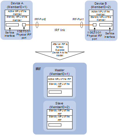
Device A and Device B in Figure 2 form an IRF fabric which has four MPUs (one active and three standby) and two interface cards. The IRF fabric manages both the physical and software resources of Device A and Device B.
This section uses Figure 2 to explain the concepts that you might encounter when working with IRF.
Operating mode
A switch can operate in either of the following two modes:
· Standalone mode—The switch cannot form an IRF fabric with other switches.
· IRF mode—The switch can connect with other switches to form an IRF fabric.
You can change the operating mode of a switch at the command-line interface (CLI).
IRF member switch roles
IRF uses two member switch roles: master and slave.
When switches form an IRF fabric, they elect a master to manage the IRF fabric, and the other switches back up the master. When the master switch fails, another switch is elect as the new master to avoid service interruption. For more information about master election, see “Master election.”
Roles of MPUs
Each member switch in an IRF fabric has one or two MPUs (also called the supervision engines) and they play different roles, as follows:
|
Role |
Description |
|
Local active main processing unit (MPU) |
The supervisor engine that manages the local switch. |
|
Local standby MPU |
The supervisor engine backs up the local active MPU, and takes over when the local active MPU fails. |
|
Global active MPU |
The active MPU of the master switch. You configure and manage the entire IRF at the command line of the global active MPU. |
|
Global standby MPU |
All MPUs except the active MPU of the master switch are global standby MPUs. |
IRF member ID
You assign the active MPU of each member switch a unique ID to identify the switch in the IRF fabric. This ID is called the “IRF member ID” of the switch. By default, the standby MPU of a switch is automatically assigned the same ID as the active MPU. You can change the standby MPU ID of a member switch to quickly recover IRF configuration for a switch that has only one MPU as described in “Performing IRF configuration fast recovery.”
IRF port
An IRF port is a logical interface for the internal connection between IRF member switches. Each IRF member switch has two IRF ports: IRF-port 1 and IRF-port 2. An IRF port is activated when you bind a physical port to it.
An IRF port can be bound to a maximum of 12 physical ports to increase the bandwidth and reliability of the IRF port.
|
|
NOTE: In standalone mode, the IRF ports are named IRF-port1 and IRF-port2. In IRF mode, the IRF ports are named IRF-portn/1 and IRF-portn/2, where n is the member ID of the switch. In this manual, IRF-port1 and IRF-port2 are used. |
Physical IRF port
Physical IRF ports are physical ports bound to an IRF port. They connect IRF member switches and forward IRF protocol packets and data packets between IRF member switches.
Physical IRF ports can be electrical ports or optical ports.
IRF partition
IRF partition occurs when an IRF fabric splits into two or more IRF fabrics because of IRF link failures, as shown in Figure 3. The partitioned IRF fabrics operate with the same IP address and cause routing and forwarding problems on the network.
|
|
NOTE: When you unplug the card where a physical IRF port resides, IRF partition might occur. Therefore, when you unplug this kind of card, make sure that there are at least two physical IRF ports in UP state, and they are not on the same card. |
IRF merge
IRF merge occurs when two partitioned IRF fabrics re-unite or when you configure and connect two independent IRF fabrics to be one IRF fabric, as shown in Figure 4.
Member priority
Member priority determines the role of a member switch during the master election process. A member with a higher priority is more likely to be a master.
The priority of a switch defaults to 1. You can modify the priority at the CLI.
Establishment, operation, and maintenance of an IRF fabric
IRF fabric management involves these stages: Connecting the IRF member switches, Topology collection, Master election, and IRF fabric management and maintenance.
Connecting the IRF member switches
Connection medium
To establish an IRF fabric, physically connect the physical IRF ports of member switches. The connection medium depends on the physical IRF ports supported by the switch:
· If you use electrical interfaces as physical IRF ports, use network cables (cross-over or straight-through) to connect them. This connection mode improves the usage of the available resources (electrical interfaces are used to forward data traffic when not bound to any IRF port, and used to forward packets between member switches when bound to IRF ports), and saves the cost as well (without the need to purchase optical module used for IRF connection).
· If you use optical ports as physical IRF ports, use fibers to connect them. This connection mode connects physical switches located very far at a distance and provides flexible application.
|
|
NOTE: A good practice is to use 10G optical Ethernet interfaces as physical IRF ports. |
Connecting requirements
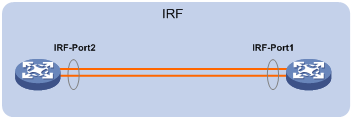
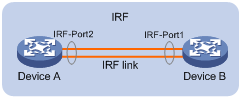
As shown in Figure 5, connect the physical ports bound to IRF-Port1 on one switch to the physical ports bound to the IRF-Port2 on its neighbor switch.
Figure 5 IRF fabric physical connection
IRF topologies
IRF member switches typically adopt a daisy chain topology or ring topology:
· The daisy chain topology is mainly used in a network where member switches are distributedly located.
· The ring topology is more reliable than the daisy chain topology. In a daisy chained IRF fabric, the failure of one link can cause the IRF fabric to partition into two independent IRF fabrics; the failure of a link in a ring topology result in a daisy chain connection, not affecting IRF services.
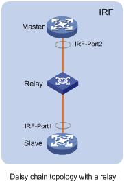
If two IRF member switches are far away from each other (for example, if they are in different cities), you can use a relay device to connect them, as shown in Figure 7.
Figure 6 IRF daisy chain topology and ring topology
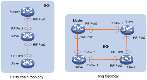
Figure 7 IRF daisy chain topology with a relay
Topology collection
Each member exchanges IRF hello packets with neighbors to collect the topology data, including IRF port connection states, member IDs, priorities, and bridge MAC addresses.
Each member is managed by its active MPU, which records its known topology information locally. At the startup of a member switch, the active MPU of the member switch records topology information of the member switch. When an IRF port of the member switch is up, the active MPU of the switch performs the following operations:
1. Periodically sends its known topology information from this port.
2. When receiving the topology information from the directly connected neighbor, it updates the local topology information.
3. If a standby MPU is available on the member switch, the active MPU synchronizes its recorded topology information to the standby MPU to ensure consistent topology information on both boards.
After all member switches have obtained topology information (known as topology convergence), the IRF fabric enters the role election stage.
Master election
Master election is held each time the topology changes, for example, when the IRF fabric is established, a new member switch is plugged in, the master switch fails or is removed, or the partitioned IRF fabrics merge.
The master is elected based on the following rules in descending order:
· The current master, even if a new member has a higher priority. (When an IRF fabric is being formed, all member switches consider themselves as the master, and this rule is skipped)
· The switch with a higher priority.
· The switch with the longest system up-time. (The member switches exchange system up-time in the IRF hello packets)
· The switch with the lowest bridge MAC address.
The IRF fabric is formed on election of the master.
|
|
NOTE: · During an IRF merge, an IRF election is held, the switches of the IRF fabric that fails the master election must reboot to re-join the IRF fabric that wins the election. Then, the switch reboots with the execution of a command. · After a master election, all slave member switches initialize and reboot with the configuration on the master, and their original configuration, even if has been saved, will be lost. |
IRF fabric management and maintenance
After the IRF fabric is established, you can access the master from any member switch to manage all the resources of the member switches.
Member ID
An IRF fabric uses member IDs to uniquely identify and manage its members. For example, if an interface on a switch that operates in standalone mode is named GigabitEthernet 3/0/1. After the switch joins an IRF fabric, it receives a member ID of 2. The name of the interface changes to GigabitEthernet 2/3/0/1.
Member ID is also used in file management. For example, when the switch operates in standalone mode, the path of a file was slot1#flash:/test.cfg. After the switch joins an IRF fabric, the path changes to chassis1#slot1#flash:/test.cfg, which indicates that the file is saved on the board in slot 1 of member switch 1. Therefore, member IDs must be unique.
|
|
NOTE: Member IDs and priorities are configured per switch. If you set the member ID or priority for a member switch, the configuration is first saved on the active MPU of the member switch, and then synchronized to the standby MPU. If the active MPU and standby MPU of a member switch keep different member IDs, the member ID kept by the active MPU is applied. For example, if the switch with the member ID of 2 has only one active MPU, after you plug in a standby MPU that keeps a member ID of 1, the member ID of the switch is still 2 and the member ID kept on the standby MPU is synchronized to 2. |
IRF fabric topology maintenance
As soon as a member switch is down or an IRF link is down, its neighbor switches broadcast the leaving of the switch to other members. When a member switch receives the leave message, it looks up its IRF topology database to determine whether the leaving switch is the master. If yes, the member switch starts a master election and updates its IRF topology database. If the leaving switch is not a master, the member switch directly updates its IRF topology database.
|
|
NOTE: An IRF port goes down only when all its physical IRF ports are down. |
IRF multi-active detection
An IRF link failure causes an IRF fabric to split in two IRF fabrics operating with the same Layer 3 configurations, such as the same IP address. To avoid IP address collisions and network problems, IRF uses the multi-active detection (MAD) mechanism to detect the presence of multiple identical IRF fabrics and handle collisions. MAD provides the following functions:
1. Detection
MAD detects multiple identical active IRF devices with the same global configuration by extending the Link Aggregation Control Protocol (LACP), the Bidirectional Forwarding Detection (BFD) protocol, or the Gratuitous Address Resolution (ARP) protocol. For more information, see ”Configuring MAD detection.”
2. Collision handling
If multiple identical active IRF fabrics are detected, only the IRF fabric that has the lowest master ID can operate in active state and forward traffic normally. MAD sets all other IRF fabrics in recovery state (disabled) and shuts down all physical ports but the console and physical IRF ports and other ports you have specified with the mad exclude interface command.
An IRF link failure triggers IRF fabric partition and causes multi-active collision. In this case, repair the failed IRF link to make the collided IRF fabrics merge into one and recover the failure. If the IRF fabric in recovery state fails before the failure is recovered, repair both the failed IRF fabric and the failed IRF link, and then the collided IRF fabrics can merge into one and the failure is recovered. If the IRF fabric in active state fails before the failure is recovered, enable the IRF fabric in recovery state at the CLI to make it take over the active IRF fabric and protect the services from being affected. Then, recover the MAD failure.
|
|
NOTE: For information about LACP, see Layer 2—LAN Switching Configuration Guide. For information about BFD, see High Availability Configuration Guide. For information about gratuitous ARP, see Layer 3—IP Services Configuration Guide. |
IRF fabric setup procedure
|
|
NOTE: For smooth cabling, be sure to plan the IRF fabric before installing the switches. |
To set up an IRF fabric, follow these steps:
1. Planning the IRF fabric size
2. Identifying the master switch and planning IRF member IDs
4. Identifying physical IRF ports on the member switches
5. Installing IRF member switches
6. Connecting the IRF member switches
Planning the IRF fabric size
The switching capacity of an IRF fabric is the sum of those of the member switches, and an IRF fabric can have up to four members.
Choose switch models and identify the number of required IRF member switches, depending on the user density and upstream bandwidth requirements. The switching capacity of an IRF fabric equals the total switching capacities of all member switches.
|
|
NOTE: To use three or four switches for an IRF fabric, you must enable enhanced IRF mode on every member switch. For more information, see “Enabling enhanced IRF mode.” |
For two S9500E switches to form an IRF fabric, the suffixes of the silkscreens on the MPUs must be the same, one B1 and one B2, or one C1 and one C2. If, for example, the MPU on one switch is LSR1SRP2C1 but LSR1SRP2B1 on the other switch, the two switches cannot form an IRF fabric.
Table 1 Support for IRF by S9500E members
|
Silkscreen suffix on the MPU of switch 1 (right) |
B1 |
B2 |
C1 |
C2 |
D1 |
|
Silkscreen suffix on the MPU of switch 2 (below) |
|||||
|
B1 |
√ |
√ |
× |
× |
× |
|
B2 |
√ |
√ |
× |
× |
× |
|
C1 |
× |
× |
√ |
√ |
× |
|
C2 |
× |
× |
√ |
√ |
× |
|
D1 |
× |
× |
× |
× |
√ |
|
|
NOTE: · In Table 1, √ indicates the IRF fabric can be formed and × indicates that the IRF fabric cannot be formed. · If a switch has two MPUs, the two MPUs must have the same silkscreen. |
Identifying the master switch and planning IRF member IDs
Determine which switch you want to use as the master in the IRF fabric, and assign the switch a priority that is higher than those of the other members. When the IRF fabric is initially formed, the switch with the highest priority will be elected as the master. For more information, see “IRF member switch roles.”
Prepare an IRF member ID assignment scheme. An IRF fabric uses member IDs to uniquely identify its members, and you must assign each IRF member switch a unique member ID. For more information, see “IRF member ID.”
Planning the IRF topology
You can create an IRF fabric in daisy chain topology, or more reliably, ring topology. A good practice is to use ring topology. For more information, see “IRF topologies.”
|
|
NOTE: If you enable enhanced IRF mode, you must use ring topology. |
Identifying physical IRF ports on the member switches
An IRF port must be bound to one or more physical IRF ports to take effect. A physical IRF port can be an Ethernet optical or electrical port (except for that of a combo port). H3C recommends using a 10 GE optical port as a physical IRF port.
An IRF port can be bount to up to 12 physical ports. H3C recommends binding each IRF port to at least two physical ports to increase the bandwidth and reliability of the IRF port.
The IRF ports at the two ends of an IRF link must be bound to the same number of physical IRF ports so that the two members can be connected through the physical IRF ports. In Figure 8, for example, the number of physical IRF ports bound to IRF-Port2 on Device A must equal that of physical IRF ports bound to IRF-Port1 on Device B.
Figure 8 IRF physical connection diagram
|
|
NOTE: Be sure to make a plan before deployment. If you configure a physical port of a switch working in standalone mode as a physical IRF port and then change the working mode of the switch to IRF mode, the services configured on the physical port will become ineffective. For more information about physical IRF ports, see “Physical IRF port.” |
Installing IRF member switches
After you finish the previously mentioned plans, install the IRF member switches as planned. For how to install a member switch, see the installation guide of the switch.
Connecting the IRF member switches
To connect two IRF member switches through Ethernet electrical ports, use a straight-through or cross cable.
To connect two IRF member switches through Ethernet optical ports, install transceiver modules on the optical ports and then connect the ports with an optical fiber. For information about appropriate transceiver modules, see the installation guide of the switch.
|
|
NOTE: To connect two IRF member switches through SFP+ ports, you can also use an SFP+ cable. |
Configuring IRF
After you install the IRF member switches, power on the switches, and log in to each IRF member switch to configure IRF. For how to log in to a switch, see Fundamentals Configuration Guide. For how to configure IRF, see “IRF fabric configuration task list.”
IRF fabric configuration task list
There are two IRF fabric configuration methods, pre-configuration and non pre-configuration. The pre-configuration method is recommended because only one switch reboot is needed to complete the configuration.
Configuration prerequisites
· Before establishing an IRF fabric, make sure that the system working mode of the member switches is the same and cannot be hybrid mode. If not, the IRF fabric cannot be established. For more information about the system working mode, see Fundamentals Configuration Guide.
· The member switches of an IRF fabric must work in the same rule match mode. This means that you must configure the acl ipv6 enable command, or the acl ipv6 disable command on the switches. For more information about the acl ipv6 command, see ACL and QoS Configuration Guide.
· The member switches of an IRF fabric must be configured with the same VPN label processing mode. This means that you must configure the vpn popgo command or the undo vpn popgo command on the switches. For more information about the vpn popgo command, see ACL and MPLS Configuration Guide.
· Before establishing an IRF fabric, check that enhanced IRF mode is enabled on all member switches or disabled on all member switches. If enhanced IRF mode is enabled on some member switches but disabled on the others, the IRF fabric cannot be established. For more information about enhanced IRF mode, see “Enabling enhanced IRF mode.”
Pre-configuration
Pre-configuration allows you to configure IRF ports, member IDs, and member priority on a switch operating in standalone mode. These configurations do not affect the running of the switch, and take effect only when the switch switches to IRF mode. Adopt this method to configure an IRF fabric before establishing it. To enable switches operating in standalone mode to form an IRF fabric, you must pre-configure their member IDs and switch their operating modes. If you configure the priority for a switch as the greatest value when the switch operates in standalone mode, this switch can win the master election and become the master after multiple switches form an IRF fabric for the first time. If you configure IRF ports for member switches operating in standalone mode, they can directly form an IRF fabric with other switches after their operating mode is switched to IRF. Pre-configurations enable the member switches to reboot only once to establish an IRF fabric.
Complete these tasks to configure an IRF fabric in pre-configuration mode:
|
Task |
Remarks |
|
|
Required. |
||
|
Optional. |
||
|
Optional. Perform this task to use three or four switches to form an IRF fabric. |
||
|
Saving the running configuration to the configuration file to be used at the next system startup |
Required. |
|
|
Required. |
||
|
Activating the physical IRF ports of the member switches by using the undo shutdown command |
Required. |
|
|
Required. |
||
|
Optional. |
||
|
Optional. |
||
|
Optional. |
||
|
Optional. |
||
|
Optional. |
||
|
Optional. |
||
|
Optional. |
||
|
Optional. |
||
|
Optional. |
||
Non pre-configuration
Non pre-configuration allows you to configure the member ID for a switch operating in standalone mode, switch the operating mode to IRF mode, and then configure parameters such as a new member ID and member priority (during the whole process, the member switches may reboot for multiple times). Use this method when you need to modify the running configuration. For example,
· Change the member ID of a switch to a specified value.
|
|
NOTE: Changing member ID might cause ineffectiveness of some member ID-related configurations. |
· Modify the priority of a member switch to make sure it is elected as the master in the next master election.
· Modify the binding between an IRF port and physical IRF ports (such as deleting a binding or adding a new binding), and the configuration of IRF ports may affect the operation of the switch (for example, causing IRF partition, or IRF merge).
Complete these tasks to configure an IRF fabric in non pre-configuration mode:
|
Task |
Remarks |
|
|
Required. |
||
|
Optional. Perform this task to use three or four switches to form an IRF fabric. |
||
|
Saving the running configuration to the configuration file to be used at the next system startup |
Required. |
|
|
Required. |
||
|
Required. |
||
|
Optional. |
||
|
Required. |
||
|
Optional. |
||
|
Optional. |
||
|
Required. |
||
|
Optional. |
||
|
Optional. |
||
|
Optional. |
||
|
Optional. |
||
|
Optional. |
||
|
Optional. |
||
|
Optional. |
||
Pre-configuring an IRF member switch in standalone mode
You can configure the IRF ports, member ID, and member priority for the switch when it is operating in standalone mode. Configurations take effect when the operating mode of the switch switches to IRF.
Binding a physical port to an IRF port
To establish IRF connection, you must assign the physical ports that connect IRF member switches to IRF ports.
An IRF port can be bound to a maximum of 12 physical ports and is known as an aggregate IRF port, which can be realized by repeatedly executing the port group interface command. This allows two switches to be connected through 12 Ethernet cables or fibers to increase the bandwidth and reliability of the IRF port.
To bind a physical port to an IRF port:
|
Step |
Command |
Remarks |
|
1. Enter system view. |
system-view |
N/A |
|
2. Enter physical IRF port view. |
interface interface-type interface-number |
N/A |
|
3. Shut down the port. |
shutdown |
Required when two member switches have more than one pair of physical IRF ports connected. |
|
4. Return to system view. |
quit |
N/A |
|
5. Create an IRF port and enter IRF port view when the switch operates in standalone mode (if the IRF port is already created, this command enters IRF port view). |
irf-port port-number |
By default, no IRF port is created on the switch. |
|
6. Bind a physical IRF port to the IRF port. |
port group interface interface-type interface-number |
By default, an IRF port is not bound to any physical IRF port. |
|
7. Verify the binding configuration. |
display irf configuration [ | { begin | exclude | include } regular-expression ] |
Optional. Make sure that the binding is as expected. If the binding is incorrect, IRF cabling errors may occur, resulting in IRF establishment failure. |
|
|
CAUTION: · A combo port cannot be bound to an IRF port. For information about combo ports, see Interface Configuration Guide. · Save the configurations to the startup configuration file so that the configurations can take effect when the switch is switched to IRF mode. · In standalone mode, binding a physical port to an IRF port does not affect the running configuration of the port. However, when the operating mode changes to IRF mode, the default configuration of the physical IRF port restores, and you can only execute the shutdown and description commands on the physical port. For more information about the shutdown and description commands, see Interface Command Reference. |
Setting a member ID for the switch
· A switch by default operates in standalone mode without an IRF member ID. You must assign it an IRF member ID before you can set it in IRF mode. You can execute the display irf configuration command and check the MemberID field. If the switch has no IRF member ID, the field displays two hyphens (--).
· To avoid member ID collision with other members when the switch is added into an IRF fabric, plan the member ID of this switch when it operates in standalone mode.
To set a member ID for the switch:
|
Step |
Command |
Remarks |
|
1. Enter system view. |
system-view |
N/A |
|
2. Set a member ID for the switch when it operates in standalone mode. |
irf member member-id |
By default, no member ID is set for the switch. |
Specifying a priority for the switch
To specify a priority for the switch:
|
Step |
Command |
Remarks |
|
1. Enter system view. |
system-view |
N/A |
|
2. Specify a priority for the switch when it operates in standalone mode. |
irf priority priority |
Optional. The priority of the switch defaults to 1. |
Enabling enhanced IRF mode
The enhanced IRF mode allows you to create an IRF fabric that has up to four member switches.
Configuration guidelines
Follow these guidelines when you configure the enhanced IRF mode::
· Each member switch must have two MPUs.
· The member switches must be in ring topology and have no relay device in between. See Figure 6 and Figure 7.
· Connect every downstream device to each IRF member switch and assign these links to one link aggregation group. See Figure 21.
· You can enable enhanced IRF mode in both standalone and IRF modes.
· In standalone mode, you can enable enhanced IRF mode directly.
· In IRF mode, the following applies:
? If neither Layer-3 (route mode) Ethernet interfaces nor VPLS and MAC-in-MAC instances exist, you can enable enhanced IRF mode directly.
? If Layer-3 Ethernet interfaces exist, you must first change them to Layer-2 (bridge mode) Ethernet interfaces at the prompt.
? If VPLS or MAC-in-MAC instances exist but no Layer-3 Ethernet interfaces exist, you must first reboot the switch at the prompt.
For more information about Layer-3 Ethernet interfaces, see Interface Configuration Guide. For more information about VPLS, see MPLS Configuration Guide. For more information about MAC-in-MAC, see Layer-2—LAN Switching Configuration Guide.
· Use the save command to save the configuration after you enable the enhanced IRF mode.
· To successfully disable enhanced IRF mode with the undo irf mode enhanced command after you enable it in IRF mode, make sure that the IRF fabric has only up to two member switches and each member switch has only one IRF port.
· To successfully merge switches into an IRF fabric, make sure that the enhanced IRF mode is enabled or disabled on all of them. Switches that use different enhanced IRF mode settings cannot form an IRF fabric.
· If the enhanced IRF mode is used, you must reboot all but one member switch to complete IRF merge.
Configuration procedure
To enable enhanced IRF mode:
|
Step |
Command |
Remarks |
|
1. Enter system view. |
system-view |
N/A |
|
2. Enable enhanced IRF mode. |
irf mode enhanced |
Not enabled by default. |
Saving the running configuration to the configuration file to be used at the next system startup
To save the running configuration to the configuration file to be used at the next system startup:
|
Task |
Command |
Remarks |
|
Save the running configuration to the configuration file to be used at the next system startup. |
save [ safely ] [ force ] |
Available in any view. |
Switching operating mode
IRF modes
The switch works in either standalone or IRF mode.
· A standalone switch does not belong to any IRF fabric. To assign a standalone switch to an IRF fabric, you must switch the operating mode to IRF mode before adding it to an IRF fabric.
· An IRF mode switch can itself form an IRF fabric or form an IRF fabric with other IRF mode switches. To save management costs and system resources, set a switch in IRF mode only when you are creating a multi-member IRF fabric.
By default, a switch is operating in standalone mode. The switch reboots when its operating mode changes to IRF mode.
Configuration file auto-conversion
When you change the operating mode of the switch from standalone to IRF, you can use the configuration file auto-conversion function to convert the startup configuration file to prevent some slot- or interface-related configurations from becoming invalid. For example, this function can convert the slot slot-number parameter set in standalone mode to the chassis chassis-number slot slot-number parameter in IRF mode, and add the chassis ID in an interface number.
Switching the operating mode to IRF mode
To switch the operating mode of the switch to IRF mode:
|
Step |
Command |
Remarks |
|
1. Enter system view. |
system-view |
N/A |
|
2. Switch the operating mode of the switch to IRF mode. |
chassis convert mode irf |
The default operating mode is standalone mode. |
|
|
NOTE: · To display the member ID of the switch, use the display irf configuration command. If the MemberID field is displayed as —, the member ID of the switch is not set yet, and you need to use the irf member command to configure it. · Base cards and the subcards can operate only when the switch operates in standalone mode. Before switching the operating mode of the switch, check whether the related services will be affected. For more information about base cards and subcards, see H3C S9500E Series Routing Switches Installation Guide. · When you switch the operating mode, the switch reboots automatically to make the change effective. H3C recommends that you save the running configuration before switching the operating mode. · To switch the operating mode of the switch to standalone mode, use the undo chassis convert mode irf command. · For a switch operating in IRF mode, you cannot configure the system working mode to hybrid. For more information about the system working mode, see Fundamentals Configuration Guide. |
Accessing an IRF fabric
Accessing the active MPU of an IRF fabric
Access an IRF fabric in one of the following ways:
· Local login—Log in on the AUX or console port of a member switch.
· Remote login—Remotely log in at a Layer 3 Ethernet interface on any member switch through Telnet, the web, or SNMP.
When you log in to an IRF fabric, you are placed at the CLI of its active MPU, regardless of at which member switch you are logged in. The active MPU of the IRF fabric is the configuration and control center of the IRF fabric. You make configuration for the IRF fabric on the active MPU, and the IRF fabric synchronizes the configurations to all standby MPUs in the virtual IRF device.
Accessing a standby MPU of an IRF fabric
You can log in to the CLI of a standby MPU of the IRF fabric to display its configurations and debug the standby MPU. When you switch from the active MPU’s CLI to the standby MPU’s CLI, you are placed in the user view of the standby MPU and the command prompt changes to <Sysname-Slave#member-ID/slot-number>, for example, <Sysname-Slave#1/0>. You can perform the following commands at the CLI of the standby MPU of an IRF fabric:
· display
· quit
· return
· system-view
· debugging
· terminal debugging
· terminal logging
· terminal monitor
· terminal trapping
To return to the CLI of the active MPU of the IRF fabric, use the quit command.
To log in to the CLI of a standby MPU in the IRF fabric:
|
Task |
Command |
Remarks |
|
Log in to a standby MPU of an IRF fabric. |
irf switch-to chassis chassis-number slot slot-number |
By default, you are placed at the CLI of the active MPU of the IRF fabric when you log in to the IRF fabric. Available in user view |
Configuring IRF member switches in IRF mode
Specifying an IRF domain ID for an IRF fabric
Introduction to domain
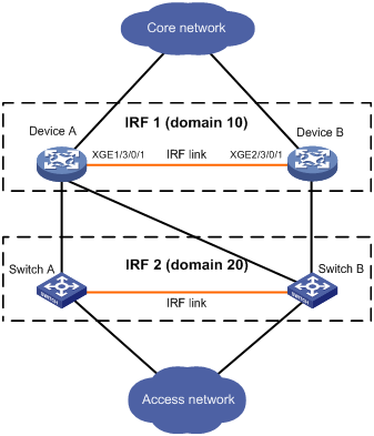
IRF uses IRF domain IDs to uniquely identify IRF fabrics. IRF domain IDs prevent IRF fabrics from interfering with one another.
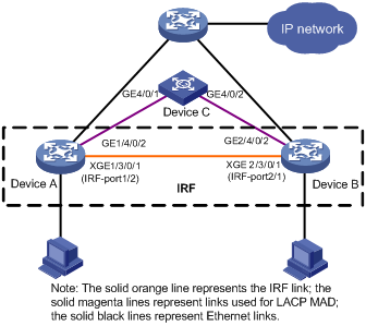
See Figure 9, Device A and Device B form IRF fabric 1, and Switch A and Switch B form IRF fabric 2. The fabrics have LACP MAD detection links between them. When a member switch in one IRF fabric receives an extended LACP packet for MAD detection, it looks at the domain ID in the packet to see whether the packet is from the local IRF fabric or from a different IRF fabric. Then, the switch can handle the packet correctly.
Figure 9 A network that comprises two IRF domains
Assigning a domain ID to an IRF fabric
To assign a domain ID to an IRF fabric:
|
Step |
Command |
Remarks |
|
1. Enter system view. |
system-view |
N/A |
|
2. Assign a domain ID to the IRF fabric. |
irf domain domain-id |
Required if LACP MAD or ARP MAD is adopted, and optional if BFD MAD is adopted. By default, the domain ID of an IRF fabric is 0. |
Configuring IRF ports
To bring the IRF function into work, you must connect the IRF member switches, assign the connecting physical ports to the appropriate IRF port on each member switch, and activate the IRF port configuration. After the IRF port configuration is activated, the IRF ports go up, a master election is held, and the switches that has failed in the election automatically reboot to join the IRF fabric as slave switches.
To configure IRF ports:
|
Step |
Command |
Remarks |
|
1. Enter system view. |
system-view |
N/A |
|
2. Enter physical IRF port view. |
interface interface-type interface-number |
N/A |
|
3. Shut down the port. |
shutdown |
N/A |
|
4. Return to system view. |
quit |
N/A |
|
5. Create an IRF port and enter IRF port view. |
irf-port member-id/port-number |
By default, no IRF port is created on the switch. |
|
6. Bind a physical IRF port to the IRF port. |
port group interface interface-type interface-number |
By default, an IRF port is not bound to any physical IRF port. |
|
7. Verify the binding configuration. |
display irf configuration [ | { begin | exclude | include } regular-expression ] |
Optional. Make sure that the binding is as expected. If the binding is incorrect, IRF cabling errors may occur, resulting in IRF establishment failure. |
|
8. Return to system view. |
quit |
N/A |
|
9. Enter physical IRF port view. |
interface interface-type interface-number |
N/A |
|
10. Bring up the port. |
undo shutdown |
N/A |
|
11. Return to system view. |
quit |
N/A |
|
|
NOTE: · After you bind a physical port to an IRF port, all services configured before the binding on the physical port become invalid. Make sure that the previous services are not interrupted. · To bind several physical IRF ports to an IRF port, execute the port group interface command multiple times. Aggregate IRF ports expand network bandwidth and provide link redundancy. The maximum number of physical IRF ports that can be bound to an IRF port is 12. When the upper limit is reached, the execution of this command fails. · Before you create or remove an IRF port binding, always shut down the physical IRF port. After you are finished, perform the undo shutdown command to bring up the port. If the system prevents you from shutting down a port for avoiding anomalies, follow the system instructions to disable its peer port. · A combo port cannot be bound to an IRF port. For information about combo ports, see Interface Configuration Guide. · If a common Ethernet interface functions as a physical IRF port and is bound to an IRF port, you can execute the shutdown, description, flow-control, oam enable, oam loopback, and oam mode commands only on the physical IRF port. For more information about the shutdown, description, and flow-control commands, see Interface Command Reference. · To make sure that the configuration takes effect at the next switch startup, save configurations to the startup configuration file that will be used at the next startup after binding a physical port to an IRF port or canceling the binding. |
Setting a member ID for a switch
An IRF fabric uses member IDs to uniquely identify its members. A lot of information and configurations relate to member IDs, such as port (physical or logical) numbers, configurations on ports, and member priorities.
After you change the member ID of a switch:
· If you do not reboot the switch, the original member ID still takes effect and all physical resources are identified by the original member ID. In the configuration file, only the IRF port numbers, configurations on IRF ports, and priority of the switch change with the member ID, other configurations do not change.
· If you save the running configuration and reboot the switch, the new member ID takes effect and all physical resources are identified by the new member ID. In the configuration file, only the IRF port numbers, configurations on IRF ports, and priority of the switch still take effect, other configurations (such as configuration for physical IRF ports, value of the chassis keyword which adopts the original member ID) no longer take effect and you need to configure them again.
To set a member ID for a switch:
|
Step |
Command |
Remarks |
|
1. Enter system view. |
system-view |
N/A |
|
2. Set a member ID for a member switch. |
irf member member-id renumber new-member-id |
Optional. The member ID of a switch defaults to 1. |
|
|
CAUTION: · Member ID changes take effect at the reboot of the switch. · Change member IDs for the switches in an IRF fabric with caution. The change might cause configuration change and even data loss. |
Specifying a priority for a member switch
To specify a priority for a member switch:
|
Step |
Command |
Remarks |
|
1. Enter system view. |
system-view |
N/A |
|
2. Specify a priority for a member switch. |
irf member member-id priority priority |
Optional. The priority of a member defaults to 1. |
Configuring a description for a member switch
You can configure a description for a member switch to identify its physical location, or for any other management purpose.
To configure a description for a member switch:
|
Step |
Command |
Remarks |
|
1. Enter system view. |
system-view |
N/A |
|
2. Configure the description for a member switch. |
irf member member-id description text |
Optional. Not configured by default. |
Specifying the preservation time of the bridge MAC address
A switch uses the bridge MAC address when it communicates with the external networks as a bridge. Some Layer 2 protocols (like LACP) use bridge MAC addresses to identify different switches. During Layer 2 packet forwarding, if the destination MAC address of a packet is the bridge MAC address of a switch, the packet is sent to this switch; otherwise, the packet is discarded. This means the bridge switch on your network must have a unique bridge MAC address. If multiple devices on your network have the same bridge MAC addresses, bridge MAC address collision occurs and the communication fails.
An IRF fabric communicates with external networks as a single switch and has a bridge MAC address. Typically, an IRF fabric uses the bridge MAC address of its master.
Bridge MAC address collision causes communication failure, and bridge MAC address switching causes traffic interruption. Properly configure the preservation time of the bridge MAC address of the IRF fabric to avoid this issue.
· Bridge MAC address collision occurs and causes network communication problems when a master leaves an IRF fabric to join another IRF fabric or to operate in a standalone manner and the IRF fabric is configured to permanently preserve the bridge MAC address, bridge MAC address collision occurs and thus causes network communication problem.
· Unnecessary bridge MAC address switching occurs causing the flow interruption when the master leaves the IRF fabric because of a reboot or link failure, and the IRF fabric is configured to change its bridge MAC address as soon as the master leaves.
To avoid these issues, configure the preservation time of the bridge MAC address of the IRF fabric according to your network status:
· Preserve for six minutes: When the master leaves, the bridge MAC address does not change for six minutes. If the master does not come back within six minutes, the IRF fabric uses the bridge MAC address of the newly elected master as its bridge MAC address. If the master leaves for a short time because of a master reboot or link failure, but then returns to the IRF fabric, specify this setting to minimize flow interruption caused by unnecessary bridge MAC address switch.
· Preserve permanently: The bridge MAC address of the IRF fabric does not change no matter how long the master leaves the IRF fabric.
· Not preserved: When the master leaves, the IRF fabric uses the bridge MAC address of the newly elected master as its bridge MAC address.
To specify the preservation time of the bridge MAC address of the IRF fabric:
|
Step |
Command |
Remarks |
|
1. Enter system view. |
system-view |
N/A |
|
2. Configure the bridge MAC address of the IRF fabric to be preserved permanently when the master leaves. |
irf mac-address persistent always |
Optional. By default, the bridge MAC address of the IRF fabric is preserved permanently when the master leaves. |
|
3. Specify the preservation time of the bridge MAC address of the IRF fabric as 6 minutes when the master leaves. |
irf mac-address persistent timer |
|
|
4. Configure that the bridge MAC address of the IRF fabric changes as soon as the master leaves. |
undo irf mac-address persistent |
|
|
CAUTION: · Bridge MAC address change may cause a temporary traffic interruption. · If two IRF fabrics have the same bridge MAC address, they cannot be merged into one IRF fabric. · If you use ARP MAD together with the spanning tree feature for an IRF fabric, enable the IRF fabric to change its bridge MAC address as soon as the master leaves by using the undo irf mac-address persistent command. · If the VRRP load balancing function is enabled when the switch operates in IRF mode, you must configure the preservation time of IRF bridge MAC address as permanently preserved (which is the default setting). For more information about VRRP, see High Availability Configuration Guide. |
Enabling auto reboot for IRF fabric merge
When merging IRF fabrics, you must reboot the member switches in the IRF fabric that has been defeated in the master election. The auto reboot function enables the IRF fabric to automatically reboot all its member switches to complete the merge.
This function can work only when it is enabled on both IRF fabrics that are merging.
To enable auto reboot for IRF fabric merge:
|
Step |
Command |
Remarks |
|
1. Enter system view. |
system-view |
N/A |
|
2. Enable auto reboot for IRF fabric merge. |
irf auto-merge enable |
Optional. Disabled by default. |
|
|
NOTE: The auto reboot function does not take effect on the IRF fabric merge caused by binding a physical port to an IRF port in IRF mode. You must manually reboot the switches that have been defeated in the master selection to complete the merge. |
Enabling automatic boot file updating
· When auto upgrade of boot files is disabled and the boot files of slaves and the master are different versions, the new member or the member with a low priority do not boot normally. Update the switch version and add the switch into the IRF fabric again.
· When auto upgrade of boot file is enabled, the IRF fabric compares its software version with that of the master as soon as a switch is added into an IRF fabric. If the versions are not the same, the switch automatically downloads the boot file from the master, reboots with the new boot file, and joins the IRF fabric again. If the downloaded boot file and the local boot file have duplicate file names, the local file is overwritten.
To enable auto upgrade of boot files for an IRF fabric:
|
Step |
Command |
Remarks |
|
1. Enter system view. |
system-view |
N/A |
|
2. Enable auto upgrade of boot files for an IRF fabric. |
irf auto-update enable |
Optional. Enabled by default. |
|
|
CAUTION: · Auto upgrade of boot files may not work normally if the software versions of the member switches in an IRF fabric are too different from each other. For more information, see the release notes for the software versions. · During auto upgrade of boot files, make sure all IRF links are OK and do not plug, unplug, or reboot the MPUs of member devices. · When you disable the auto upgrade of boot files, the software versions of the switches must be the same. If not, an IRF fabric cannot be established. · Make sure that the model of the switch matches the software version of the master before adding the switch into the IRF fabric. If the model of the switch to be added does not match the software version of the master, auto upgrade may not function normally. · After automatically loading the master’s boot file, a slave configures the file as the boot file to be used at the next boot and reboots automatically. · Make sure that there is enough space on the slave’s flash or CF card where the system boot file resides to make the auto upgrade succeeds. |
Setting the IRF link down report delay
After setting the delay time for the link layer to report a link-down event:
· If the IRF link state changes from up to down, the port does not immediately report the change to the IRF fabric. If the IRF link state is still down when the configured time is reached, the port reports the change to the IRF fabric.
· If the link state changes from down to up, the link layer immediately reports the event to the IRF fabric.
Use this function to avoid unnecessary IRF fabric partition and merge caused by frequent link state changes of a port.
To set the IRF link down report delay:
|
Step |
Command |
Remarks |
|
1. Enter system view. |
system-view |
N/A |
|
2. Set the IRF link down report delay. |
irf link-delay interval |
Optional. 0 milliseconds by default. |
|
CAUTION: The recommended value of the interval argument is in the range 200 to 500, in milliseconds. Setting the delay time too long can cause the IRF fabric to not address topology changes in time, which can slow the recovery process. |
Enabling IRF link failure detection and auto-recovery
IRF link failure detection and auto-recovery automatically check the health of IRF links and automatically make link recovery attempts when a failed IRF link is detected. The two functions are helpful for IRF fabrics that have more than one IRF link.
To enable IRF link failure detection and auto-recovery:
|
Step |
Command |
Remarks |
|
1. Enter system view. |
system-view |
N/A |
|
2. Enable IRF link failure detection. |
irf link-status detect enable |
Optional. Enabled by default. IRF link failure detection must be enabled when a relay device is present between two member devices. |
|
3. Enable IRF link auto-recovery. |
irf link-status auto-recovery enable |
Optional. Enabled by default. You can enable the IRF link auto-recovery function only when the IRF link failure detection function is enabled. |
When the IRF link failure detection function detects an IRF link failure, it handles the physical IRF port depending on the status of IRF link auto-recovery:
· If IRF link auto-recovery is enabled, disables the physical IRF port to receive packets, and outputs a log message, for example, “IRF member port GigabitEthernet1/4/0/1 does not work in receive direction,” every 10 seconds. After that, if the IRF fabric splits, the physical IRF port can continue to work normally. If you disable IRF link failure detection or auto-recovery, the physical IRF port shuts down. To bring the port up, use the undo shutdown command.
· If IRF link auto-recovery is disabled, shuts down the physical IRF port. After that, the port stays in DOWN state, even if you enable IRF link auto-recovery function. (To bring the port up, use the undo shutdown command.) If the IRF fabric splits, the physical IRF ports in DOWN state change to the previous state.
Configuring MAD detection
You have the following MAD mechanisms for detecting multi-active collisions in different network scenarios:
· LACP MAD
· BFD MAD
· ARP MAD.
These MAD detection mechanisms operate independently, and you can configure all of them for an IRF fabric.
Configuring LACP MAD
1. LACP MAD detection mechanism
With LACP MAD, an IRF member switch sends extended LACP data units (LACPDUs) with a type length value (TLV) that conveys the domain ID and active ID of the IRF fabric for detecting an IRF split. The domain ID uniquely identifies an IRF device in the network, and the active ID is identical to the member ID of the master switch in the IRF fabric.
An IRF member switch compares the domain ID and the active ID in each received extended LACPDU with its domain ID and active ID:
? If the domain IDs are different, the extended LACPDU is from a different IRF fabric, and the switch does not continue to process the extended LACPDU with the MAD mechanism.
? If the domain IDs are the same, the switch compares the active IDs. If the active IDs are different, the IRF fabric has split; if the active IDs are the same, the IRF fabric is operating normally.
2. Network requirements
Every IRF member switch has a link with an intermediate switch, and all these links form a dynamic link aggregation group, as shown in Figure 10.
The intermediate switch must be an H3C switch capable of handling extended LACPDUs that carry the Active ID field. For more information about LACP and the support of the switch for extended LACPDUs, see Layer 2—LAN Switching Configuration Guide.
|
|
CAUTION: If the intermediate switch is in an IRF fabric, you must assign this fabric a different domain ID than the LACP MAD-enabled fabric to avoid false detection of IRF partition. |
3. Configuring LACP MAD detection
Configure LACP MAD detection by following these steps:
a. Create an aggregate interface (also required on the intermediate device);
b. Configure the aggregation group to work in dynamic aggregation mode; (also required on the intermediate device)
c. Enable LACP MAD detection on the dynamic aggregate interface;
d. Add member ports to the aggregation group.(also required on the intermediate device)
To configure LACP MAD detection:
|
Step |
Command |
Remarks |
|
1. Enter system view. |
system-view |
N/A |
|
2. Assign a domain ID to the IRF fabric. |
irf domain domain-id |
By default, the domain ID of an IRF fabric is 0. |
|
3. Create an aggregate interface. |
interface bridge-aggregation interface-number |
N/A |
|
4. Configure the aggregation group to work in dynamic aggregation mode. |
link-aggregation mode dynamic |
By default, the aggregation group works in static aggregation mode. |
|
5. Enable LACP MAD detection. |
mad enable |
Disabled by default. This command can be configured on both static and dynamic aggregate interfaces, but it takes effect only on dynamic aggregate interfaces. This is because this detection approach depends on LACP. |
|
6. Return to system view. |
quit |
N/A |
|
7. Enter Ethernet interface view. |
interface interface-type interface-number |
N/A |
|
8. Assign the current Ethernet interface to the specified aggregation group. |
port link-aggregation group number |
N/A |
Configuring BFD MAD
1. BFD MAD detection mechanism
BFD MAD is implemented with the BFD protocol. To configure BFD MAD detection, configure a MAD IP address on a BFD-enabled Layer 3 interface for each member switch. This MAD address identifies the member during BFD MAD detection. The MAD IP addresses assigned to the member switches must belong to the same network segment.
? When the IRF fabric operates normally, only the MAD IP address of the master is effective and the BFD session is down. You can use the display bfd session command to display the status of BFD sessions. The Session State field shows the session status.
? When the IRF fabric partitions, the MAD IP addresses of the masters in different IRF fabrics become effective to activate the BFD sessions to detect for multi-active IRF fabric collision.
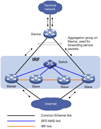
2. Network requirements
If the IRF fabric has only two member switches, BFD MAD detection can work with or without intermediate switches. In a BFD MAD network without an intermediate switch, connect the IRF member switches with a dedicated BFD MAD link, as shown in Figure 11. The interfaces connected by the BFD MAD link must belong to the same VLAN. In VLAN interface view, assign different IP addresses on the same network segment for different member switches.
If the IRF fabric has three or four member switches, there must be intermediate switches. In a BFD MAD network with an intermediate switch, connect each IRF member switch to the intermediate switch with a dedicated BFD MAD link, as shown in Figure 12. The interfaces connected by BFD MAD links must belong to the same VLAN, and you must assign different IP addresses on the same network segment for different member switches’ VLAN interfaces.
|
|
CAUTION: A Layer 3 interface used for BFD MAD must be dedicated. Do not configure any other services on them. Otherwise, both the configured services and the BFD MAD detection function can be affected. |
Figure 11 Network diagram (without intermediate switches)
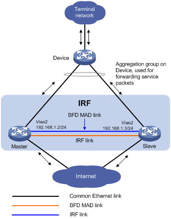
Figure 12 Network diagram (with an intermediate switch)
3. Configure BFD MAD detection
Configure BFD MAD detection in the following order:
a. Create a VLAN dedicated to BFD MAD detection. This is also required on an intermediate switch, if it exists.
b. Select the physical IRF ports for BFD MAD detection (at least one on each member switch) and add them into the detection-dedicated VLAN. This is also required on an intermediate switch, if it exists.
c. Create VLAN interfaces for the detection-dedicated VLAN, enable BFD MAD detection on these interfaces, and then assign MAD IP addresses for them.
To configure BFD MAD:
|
Step |
Command |
Remarks |
|
1. Enter system view. |
system-view |
N/A |
|
2. Create a new VLAN dedicated to BFD MAD detection. |
vlan vlan-id |
The default VLAN on the switch is VLAN 1. |
|
3. Return to system view. |
quit |
N/A |
|
4. Enter Ethernet interface view. |
interface interface-type interface-number |
N/A |
|
5. Assign the port to the VLAN dedicated to BFD MAD detection. |
·
Access port: ·
Trunk port: ·
Hybrid port: |
Select one approach according to the port type. BFD MAD detection has no requirement on the link type of the detection port, and you do not need to modify the current link type. By default, the port is an access port. |
|
6. Return to system view. |
quit |
N/A |
|
7. Enter VLAN interface view. |
interface vlan-interface interface-number |
N/A |
|
8. Enable BFD MAD. |
mad bfd enable |
Disabled by default. |
|
9. Configure a MAD IP address for the VLAN interface on the specified member. |
mad ip address ip-address { mask | mask-length } member member-id |
By default, no MAD IP address is configured for any interface. |
|
|
NOTE: · The VLAN enabled with BFD MAD detection must be dedicated to the BFD MAD detection and cannot be configured with any other service. · A VLAN interface enabled with BFD MAD detection and the interfaces of this VLAN do not support any Layer 2 and Layer 3 protocol applications, including ARP and LACP. · If the VLAN dedicated to BFD MAD detection contains a trunk port that permits the packets of multiple VLANs, make sure that the default VLAN of the trunk port is not the VLAN dedicated to BFD MAD detection. Otherwise, services configured on the trunk port may be affected. · You cannot enable BFD MAD detection on VLAN-interface 1. · The MAD function is mutually exclusive with the VPN. Layer 3 interfaces that have BFD MAD enabled cannot be bound to the VPN. · Do not enable the spanning tree function on any port in a BFD MAD VLAN. The MAD function is mutually exclusive with the spanning tree function. · You can assign the MAD IP address to an interface used for BFD MAD detection only with the mad ip address command. You cannot configure other IP addresses for it. This includes common IP address or VRRP virtual IP address configured with the ip address command. |
Configuring ARP MAD
1. ARP MAD detection mechanism
With ARP MAD, an IRF member switch sends extended gratuitous ARP packets that convey the domain ID and active ID of the IRF fabric for detecting an IRF split. The domain ID uniquely identifies an IRF fabric in the network, and the active ID is identical to the member ID of the master switch in the IRF fabric.
An IRF member switch compares the domain ID and the active ID in each received extended gratuitous ARP packet with its domain ID and active ID:
? If the domain IDs are different, the extended gratuitous ARP packet is from a different IRF fabric, and the switch does not continue to process the packet with the MAD mechanism.
? If the domain IDs are the same, the switch compares the active IDs: If the active IDs are different, the IRF fabric has split; if the active IDs are the same, the IRF fabric is operating normally.
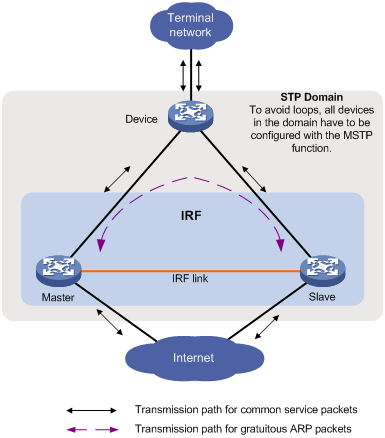
2. Network requirements
Set up ARP MAD links between neighbor IRF member switches, or more commonly, between each IRF member switch and an intermediate switch (see Figure 13). If an intermediate switch is used, you must enable MSTP on the intermediate switch and the IRF fabric.
|
|
CAUTION: If the intermediate device is in an IRF fabric, you must assign this fabric a different domain ID than the ARP MAD-enabled fabric to avoid false detection of IRF partition. |
3. Configure ARP MAD detection:
|
Step |
Command |
Remarks |
|
1. Enter system view. |
system-view |
N/A |
|
2. Assign a domain ID to the IRF fabric. |
irf domain domain-id |
By default, the domain ID of an IRF fabric is 0. |
|
3. Create a new VLAN dedicated to ARP MAD detection. |
vlan vlan-id |
The default VLAN on the switch is VLAN 1. |
|
4. Return to system view. |
quit |
N/A |
|
5. Enter Ethernet interface view. |
interface interface-type interface-number |
N/A |
|
6. Assign the port to the VLAN dedicated to ARP MAD detection. |
·
Access port ·
Trunk port ·
Hybrid port |
You can select one approach according to the port type. ARP MAD detection has no requirement on the link type of the detection port, and you do not need to modify the current link type. By default, the port is an access port. |
|
7. Return to system view. |
quit |
N/A |
|
8. Enter VLAN interface view. |
interface vlan-interface interface-number |
N/A |
|
9. Assign the interface an IP address. |
ip address ip-address { mask | mask-length } |
No IP address is assigned to any VLAN interface by default. |
|
10. Enable ARP MAD. |
mad arp enable |
By default, ARP MAD is disabled. |
Excluding a port from the shut down action upon detection of multi-active collision
By default, all service ports of an IRF fabric except the console and physical IRF ports shut down when the IRF fabric transits to recovery state upon detection of a multi-active collision. You can exclude a service port from the shut down action for management or other special purposes. For example, you can exclude a port from the shut down action, so you can telnet to the port for managing the switch. For another example, you can exclude a VLAN interface and its Layer 2 Ethernet interface from the shut down action, so you can log in through the VLAN interface.
To configure a port not to shut down when the IRF fabric changes to recovery state:
|
Step |
Command |
Remarks |
|
1. Enter system view. |
system-view |
N/A |
|
2. Configure a service port not to shut down when the IRF fabric transits to recovery state. |
mad exclude interface interface-type interface-number |
When an IRF fabric transits to recovery state, all its service ports are shut down by default. |
Manually recovering an IRF fabric
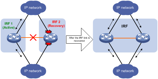
An IRF link failure causes an IRF fabric to divide into two IRF fabrics and thus multi-active collision occurs. When the system detects the collision, it holds a role election between the two collided IRF fabrics. The IRF fabric whose master’s member ID is smaller prevails and operates normally. The state of the other IRF fabric transits to recovery state and temporarily cannot forward data packets. In this case, recover the IRF fabric by repairing the IRF link first (the switch tries to automatically repair the failed IRF links. If the reparation fails, manually repair the failed links.) . When the link is recovered, the IRF fabric in active state and the IRF fabric in recovery state automatically merge into one. The IRF fabrics can merge into one only when you reboot the specified IRF fabric. If you reboot the IRF fabric in recovery state, two IRF fabrics merge into one. Service ports that were shut down and belonged to the IRF fabric in recovery state automatically restore their original physical state, and the whole IRF fabric recovers, as shown in Figure 14. If you reboot the IRF fabric in active state, two IRF fabrics merge into one. To enable the whole IRF fabric to recover in this case, execute the mad restore command to manually restore the original physical state of the service ports that were shut down and belonged to the IRF fabric in recovery state, as shown in Figure 15.
Figure 14 Recovering the IRF fabric when IRF link failure occurs
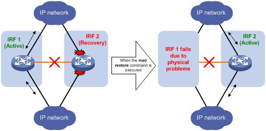
If the IRF fabric in active state fails due to exceptions (a member fails or link failure occurs, for example) before the IRF link is recovered, as shown in Figure 15, enable IRF fabric 2 (in recovery state) at the CLI by executing the mad restore command. Then, the state of IRF fabric 2 changes from recovery to active without the need of rebooting and takes over IRF fabric 1. Repair the IRF links. Then, the two IRF fabrics merge when the IRF link failure is recovered, and the IRF fabric recovers.
Figure 15 Recovering the IRF fabric when the IRF link failure occurs and the IRF fabric in active state fails
To manually recover an IRF fabric in recovery state:
|
Step |
Command |
|
1. Enter system view. |
system-view |
|
2. Recover an IRF fabric in recovery state. |
mad restore |
Performing IRF configuration fast recovery
If a member switch has only one MPU and that board is corrupted, use the following fast recover function to avoid complicated IRF configuration.
Configuration prerequisites
· H3C recommends that you perform the fast recovery operation when the switch operates in IRF mode.
· Save the IRF configuration file on all MPUs of the IRF fabric. Assume the name of the configuration file is a.cfg.
Configuration procedures
Scenario I: Member switch 1 has one MPU, and it is corrupted. Member switch 2 has two MPUs.
1. Modify the member ID of the standby MPU on member switch 2 to make it consistent with that of member switch 1.
2. Unplug the corrupted MPU on member switch 1, and insert the standby MPU of member switch 2 into member switch 1.
3. Configure IRF ports on member switch 1, and connect member switch 1 to member switch 2 through physical IRF ports.
The fast recovery is completed.
Scenario II: Both member switches have only one MPU, and the MPU on member switch 1 is corrupted.
1. Insert another MPU into member switch 2 and use it as the standby MPU of member switch 2.
2. Copy the configuration file a.cfg on the active MPU of member switch 2 to the standby MPU, and set the file as the startup configuration file to be used at the next startup.
3. Modify the member ID of the standby MPU on member switch 2 to make it consistent with that of member switch 1.
4. Unplug the corrupted MPU on member switch 1, and insert the standby MPU of member switch 2 into member switch 1.
5. Configure IRF ports on member switch 1, and connect member switch 1 to member switch 2 through physical IRF ports.
The fast recovery is completed.
To modify the member ID of the standby MPU:
|
Task |
Command |
Remarks |
|
Modify the member ID of the standby MPU in user view. |
In IRF mode: set irf chassis chassis-number slot slot-number member-id member-id In standalone mode: set irf slot slot-number member-id member-id |
This command is applicable to the fast recovery of the IRF only. If you use this command in other cases, unknown errors may occur. Use it with caution. |
Displaying and maintaining an IRF fabric
|
Task |
Command |
Remarks |
|
Display information about the IRF fabric. |
display irf [ | { begin | exclude | include } regular-expression ] |
Available in any view |
|
Display topology information about the IRF fabric. |
display irf topology [ | { begin | exclude | include } regular-expression ] |
Available in any view |
|
Display all members’ configurations that take effect after device reboots. |
display irf configuration [ | { begin | exclude | include } regular-expression ] |
Available in any view |
|
Display configuration information about MAD detection. |
display mad [ verbose ] [ | { begin | exclude | include } regular-expression ] |
Available in any view |
|
Display restricted ports. |
display restricted port [ chassis chassis-number slot slot-number ] [ | { begin | exclude | include } regular-expression ] |
Available in any view A restricted port does not receive or forward multicast packets. |
|
|
NOTE: A restricted port in the system does not receive or forward multicast packets. |
IRF fabric configuration examples
|
|
NOTE: By default, Ethernet, VLAN, and aggregate interfaces are down. To configure these types of interfaces, execute the undo shutdown command to bring them up. |
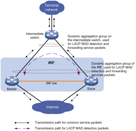
LACP MAD detection-enabled configuration example (non pre-configuration mode)
Network requirements
The network as shown in Figure 16 is outgrowing the forwarding capability of the existing core switch, (Device A).
To address business growth, increase the number of ports at the access layer while protecting the current investments of the customer and maintaining ease of management and maintenance.
Configuration considerations
· To increase the number of access ports, additional devices are needed. In this example, Device B is added.
· To offset the risk of IRF fabric partition, configure MAD to detect multi-active collisions. In this example, LACP MAD is adopted because there are many access switches. For LACP MAD, use an intermediate switch that supports extended LACPDUs.
Configuration procedure
1. Configure Device A
# Change the operating mode of Device A to IRF.
<Sysname> system-view
[Sysname] irf member 1
Info: Member ID change will take effect after the switch reboots and operates in IRF mode.
[Sysname] chassis convert mode irf
The device will switch to IRF mode and reboot. You are recommended to save the current running configuration and specify the configuration file for the next startup. Continue? [Y/N]:y
Do you want to convert the content of the next startup configuration file flash:/startup.cfg to make it available in IRF mode? [Y/N]:y
Please wait...
Saving the converted configuration file to the main board succeeded.
Slot 1:
Saving the converted configuration file succeeded.
Now rebooting, please wait...
Device A reboots automatically to switch its operating mode.
# Create IRF port 1/2 and bind it with the physical IRF port Ten-GigabitEthernet 1/3/0/1.
<Sysname> system-view
[Sysname] irf-port 1/2
[Sysname-irf-port 1/2] port group interface Ten-Gigabitethernet 1/3/0/1
[Sysname-irf-port 1/2] save
The current configuration will be written to the device. Are you sure? [Y/N]:y
Please input the file name(*.cfg)[flash:/cfa0555.cfg]
(To leave the existing filename unchanged, press the enter key):
flash:/cfa0555.cfg exists, overwrite? [Y/N]:y
Validating file. Please wait.....................................
The current configuration is saved to the active main board successfully.
Configuration is saved to device successfully.
2. Configure Device B
# Change the operating mode of Device B to IRF.
<Sysname> system-view
[Sysname] irf member 2
Info: Member ID change will take effect after the switch reboots and operates in IRF mode.
[Sysname] chassis convert mode irf
The device will switch to IRF mode and reboot. You are recommended to save the current running configuration and specify the configuration file for the next startup. Continue? [Y/N]:y
Do you want to convert the content of the next startup configuration file flash:/startup.cfg to make it available in IRF mode? [Y/N]:y
Please wait...
Saving the converted configuration file to the main board succeeded.
Slot 1:
Saving the converted configuration file succeeded.
Now rebooting, please wait...
Device B reboots automatically to switch its operating mode.
# Create IRF port 2/1 and bind it with the physical IRF port Ten-GigabitEthernet 2/3/0/1.
<Sysname> system-view
[Sysname] irf-port 2/1
[Sysname-irf-port 2/1] port group interface Ten-Gigabitethernet 2/3/0/1
[Sysname-irf-port 2/1] save
The current configuration will be written to the device. Are you sure? [Y/N]:y
Please input the file name(*.cfg)[flash:/cfa0666.cfg]
(To leave the existing filename unchanged, press the enter key):
flash:/cfa0666.cfg exists, overwrite? [Y/N]:y
Validating file. Please wait.....................................
The current configuration is saved to the active main board successfully.
Configuration is saved to device successfully.
3. Connect the two devices as shown in Figure 16 with IRF cables, and then reboot Device B. Power them on, and the IRF is established.
4. Configure LACP MAD
# Set the domain ID of the IRF fabric to 1.
<Sysname> system-view
[Sysname] irf domain 1
# Create a dynamic aggregate interface and enable LACP MAD.
<Sysname> system-view
[Sysname] interface bridge-aggregation 2
[Sysname-Bridge-Aggregation2] link-aggregation mode dynamic
[Sysname-Bridge-Aggregation2] mad enable
You need to assign a domain ID (range: 0-4294967295)
[Current domain is: 1]:
The assigned domain ID is: 1
Info: MAD LACP only enable on dynamic aggregation interface
[Sysname-Bridge-Aggregation2] quit
# Assign ports 1/4/0/2 and 2/4/0/2 to the aggregate interface for LACP MAD detection.
Sysname] interface Gigabitethernet 1/4/0/2
[Sysname-GigabitEthernet1/4/0/2] port link-aggregation group 2
[Sysname-GigabitEthernet1/4/0/2] quit
[Sysname] interface Gigabitethernet 2/4/0/2
[Sysname-GigabitEthernet2/4/0/2] port link-aggregation group 2
5. Configure Device C as the intermediate device
Acting as the intermediate device, Device C forwards and processes extended LACPDUs sent between Device A and Device B for MAD detection.
|
|
CAUTION: If the intermediate device is in an IRF fabric, you must assign this fabric a different domain ID than the LACP MAD-enabled fabric. |
# Create a dynamic aggregate interface.
<Sysname> system-view
[Sysname] interface bridge-aggregation 2
[Sysname-Bridge-Aggregation2] link-aggregation mode dynamic
[Sysname-Bridge-Aggregation2] quit
# Assign ports GigabitEthernet 4/0/1 and GigabitEthernet 4/0/2 to the dynamic aggregate interface.
[Sysname] interface Gigabitethernet 4/0/1
[Sysname-GigabitEthernet4/0/1] port link-aggregation group 2
[Sysname-GigabitEthernet4/0/1] quit
[Sysname] interface Gigabitethernet 4/0/2
[Sysname-GigabitEthernet4/0/2] port link-aggregation group 2
|
|
NOTE: On the switch that supports pre-configurations, you can also configure the LACP MAD; on the switch not supporting pre-configurations, you can also configure the BFD MAD. |
BFD MAD detection-enabled IRF configuration example (pre-configuration mode)
Network requirements
The network as shown in Figure 17 is outgrowing the forwarding capability of the existing core switch (Device A).
To address business growth, scale up the network to extend its forwarding capability while protecting the present investments of the customer. Ease of management and maintenance must also be ensured.
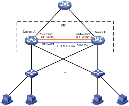
Configuration considerations
· Device A is located at the distribution layer of the network. To improve the forwarding capability at this layer, additional devices are needed. In this example, Device B is added.
· To offset the risk of IRF fabric partition, configure MAD to detect multi-active collisions. In this example, BFD MAD is adopted.
Configuration procedure
1. Configure Device A
# Set the member ID of Device A to 1, priority to 12, create IRF port 2, and bind it to physical port Ten-GigabitEthernet 3/0/1.
<Sysname> system-view
[Sysname] irf member 1
Info: Member ID change will take effect after the switch reboots and operates in IRF mode.
[Sysname] irf priority 12
[Sysname] irf-port 2
[Sysname-irf-port 2] port group interface ten-gigabitethernet 3/0/1
[Sysname-irf-port 2] quit
# Save the running configuration to the configuration file for next startup.
[Sysname] save
The current configuration will be written to the device. Are you sure? [Y/N]:y
Please input the file name(*.cfg)[flash:/cfa0516.cfg]
(To leave the existing filename unchanged, press the enter key):
flash:/cfa0516.cfg exists, overwrite? [Y/N]:y
Validating file. Please wait.....................................
The current configuration is saved to the active main board successfully.
Configuration is saved to device successfully.
# Change the operating mode of Device A to IRF.
<Sysname> system-view
[Sysname] chassis convert mode irf
The device will switch to IRF mode and reboot. You are recommended to save the current running configuration and specify the configuration file for the next startup. Continue? [Y/N]:y
Do you want to convert the content of the next startup configuration file flash:/startup.cfg to make it available in IRF mode? [Y/N]:y
Please wait...
Saving the converted configuration file to the main board succeeded.
Slot 1:
Saving the converted configuration file succeeded.
Now rebooting, please wait...
Device A operates in IRF mode after reboot.
2. Configure Device B
# Set the member ID of Device B to 2, priority to 26, create IRF port 1, and bind it to physical port Ten-GigabitEthernet 3/0/1.
<Sysname> system-view
[Sysname] irf member 2
Info: Member ID change will take effect after the switch reboots and operates in IRF mode.
[Sysname] irf priority 26
[Sysname] irf-port 1
[Sysname-irf-port 1] port group interface ten-gigabitethernet 3/0/1
[Sysname-irf-port 1] quit
# Save the running configuration to the configuration file for next startup.
[Sysname] save
The current configuration will be written to the device. Are you sure? [Y/N]:y
Please input the file name(*.cfg)[flash:/cfa0516.cfg]
(To leave the existing filename unchanged, press the enter key):
flash:/cfa0516.cfg exists, overwrite? [Y/N]:y
Validating file. Please wait.....................................
The current configuration is saved to the active main board successfully.
Configuration is saved to device successfully.
# Connect the two devices as shown in Figure 17.
# Switch the operating mode of Device B to IRF.
<Sysname> system-view
[Sysname] chassis convert mode irf
The device will switch to IRF mode and reboot. You are recommended to save the current running configuration and specify the configuration file for the next startup. Continue? [Y/N]:y
Do you want to convert the content of the next startup configuration file flash:/startup.cfg to make it available in IRF mode? [Y/N]:y
Please wait...
Saving the converted configuration file to the main board succeeded.
Slot 1:
Saving the converted configuration file succeeded.
Now rebooting, please wait...
Device B and Device A form an IRF fabric when Device B reboots.
3. Configure BFD MAD
# Create VLAN 3, and add port GigabitEthernet 1/4/0/1 (located on Device A) and port GigabitEthernet 2/4/0/1 (located on Device B) to VLAN 3.
<Sysname> system-view
[Sysname] vlan 3
[Sysname-vlan3] port gigabitethernet 1/4/0/1 gigabitethernet 2/4/0/1
[Sysname-vlan3] quit
# Create VLAN-interface 3 and configure a MAD IP address for the interface.
[Sysname] interface vlan-interface 3
[Sysname-Vlan-interface3] mad bfd enable
[Sysname-Vlan-interface3] mad ip address 192.168.2.1 24 member 1
[Sysname-Vlan-interface3] mad ip address 192.168.2.2 24 member 2
[Sysname-Vlan-interface3] quit
# Because BFD MAD detection and spanning tee function are mutually exclusive, disable the spanning tree function on ports GigabitEthernet 1/4/0/1 and GigabitEthernet 2/4/0/1.
[Sysname] interface Gigabitethernet 1/4/0/1
[Sysname-Gigabitethernet1/4/0/1] undo stp enable
[Sysname-Gigabitethernet1/4/0/1] quit
[Sysname] interface Gigabitethernet 2/4/0/1
[Sysname-Gigabitethernet2/4/0/1] undo stp enable
ARP MAD detection-enabled IRF configuration example (pre-configuration mode)
Network requirements
The network (see Figure 18) is outgrowing the forwarding capability of the existing core switch, namely, Device A.
To address business growth, scale up the network to extend its forwarding capability while protecting the present investments of the customer. Ease of management and maintenance must also be ensured.
Configuration considerations
· Device A is located at the distribution layer of the network. To improve the forwarding capability at this layer, additional devices are needed. In this example, Device B is added.
· To offset the risk of IRF fabric partition, configure MAD to detect multi-active collisions. In this example, ARP MAD is adopted, and the ARP MAD packets are transmitted over dual links connected to Device C. Enable the spanning tree function on the IRF fabric and Device to prevent loops.
Configuration procedure
1. Configure Device A
# Set the member ID of Device A to 1, create IRF port 2, and bind it to physical port Ten-GigabitEthernet 3/0/1.
<Sysname> system-view
[Sysname] irf member 1
Info: Member ID change will take effect after the switch reboots and operates in IRF mode.
[Sysname] irf-port 2
[Sysname-irf-port2] port group interface ten-gigabitethernet 3/0/1
[Sysname-irf-port2] quit
# Save the running configuration to the configuration file for next startup.
[Sysname] save
The current configuration will be written to the device. Are you sure? [Y/N]:y
Please input the file name(*.cfg)[flash:/cfa0516.cfg]
(To leave the existing filename unchanged, press the enter key):
flash:/cfa0516.cfg exists, overwrite? [Y/N]:y
Validating file. Please wait.....................................
The current configuration is saved to the active main board successfully.
Configuration is saved to device successfully.
# Change the operating mode of Device A to IRF.
<Sysname> system-view
[Sysname] chassis convert mode irf
The device will switch to IRF mode and reboot. You are recommended to save the current running configuration and specify the configuration file for the next startup. Continue? [Y/N]:y
Do you want to convert the content of the next startup configuration file flash:/startup.cfg to make it available in IRF mode? [Y/N]:y
Please wait...
Saving the converted configuration file to the main board succeeded.
Slot 1:
Saving the converted configuration file succeeded.
Now rebooting, please wait...
Device A operates in IRF mode after reboot.
2. Configure Device B
# Set the member ID of Device B to 2, create IRF port 1, and bind it to physical port Ten-GigabitEthernet 3/0/1.
<Sysname> system-view
[Sysname] irf member 2
Info: Member ID change will take effect after the switch reboots and operates in IRF mode.
[Sysname] irf-port 1
[Sysname-irf-port1] port group interface ten-gigabitethernet 3/0/1
[Sysname-irf-port1] quit
# Save the running configuration to the configuration file for next startup.
[Sysname] save
The current configuration will be written to the device. Are you sure? [Y/N]:y
Please input the file name(*.cfg)[flash:/cfa0516.cfg]
(To leave the existing filename unchanged, press the enter key):
flash:/cfa0516.cfg exists, overwrite? [Y/N]:y
Validating file. Please wait.....................................
The current configuration is saved to the active main board successfully.
Configuration is saved to device successfully.
# Connect the two devices as shown in Figure 18.
# Switch the operating mode of Device B to IRF.
<Sysname> system-view
[Sysname] chassis convert mode irf
The device will switch to IRF mode and reboot. You are recommended to save the current running configuration and specify the configuration file for the next startup. Continue? [Y/N]:y
Do you want to convert the content of the next startup configuration file flash:/startup.cfg to make it available in IRF mode? [Y/N]:y
Please wait...
Saving the converted configuration file to the main board succeeded.
Slot 1:
Saving the converted configuration file succeeded.
Now rebooting, please wait...
Device B and Device A form an IRF after Device B reboots.
3. Configure the IRF fabric
# Set the domain ID of the IRF fabric to 1.
[Sysname] irf domain 1
# Enable the spanning tree function globally on the IRF fabric to prevent loops.
<Sysname> system-view
[Sysname] stp enable
# Configure that the bridge MAC address of the IRF fabric changes as soon as the master leaves.
[Sysname] undo irf mac-address persistent
4. Configure ARP MAD
# Create VLAN 3, and add port GigabitEthernet 1/4/0/2 (located on Device A) and port GigabitEthernet 2/4/0/2(located on Device B) to VLAN 3.
<Sysname> system-view
[Sysname] vlan 3
[Sysname-vlan3] port gigabitethernet 1/4/0/2 gigabitethernet 2/4/0/2
[Sysname-vlan3] quit
# Create VLAN-interface 3, assign it an IP address, and enable ARP MAD on the interface.
[Sysname] interface vlan-interface 3
[Sysname-Vlan-interface3] mad arp enable
You need to assign a domain ID (range: 0-4294967295)
[Current domain is: 1]:
The assigned domain ID is: 1
[Sysname-Vlan-interface3] ip address 192.168.2.1 24
5. Configure Device C as the intermediate device
Acting as the intermediate device, Device C forwards and processes gratuitous ARP packets sent between Device A and Device B for MAD detection.
|
|
CAUTION: If the intermediate device is in an IRF fabric, you must assign this fabric a different domain ID than the ARP MAD-enabled fabric. |
# Enable the spanning tree function globally on Device C to prevent loops.
<DeviceC> system-view
[DeviceC] stp enable
# Create VLAN 3, and add port GigabitEthernet 4/0/1 and port GigabitEthernet 4/0/2 to VLAN 3 to forward ARP MAD packets.
[DeviceC] vlan 3
[DeviceC-vlan3] port gigabitethernet 4/0/1 gigabitethernet 4/0/2
[DeviceC-vlan3] quit
Switching the operating mode of IRF member switches from IRF to standalone
Network requirements
As shown in Figure 19, the IRF fabric operates normally. Device A and Device B are IRF member switches.
To adapt the network to changes, switch the operating mode of Device A and Device B from IRF to standalone.

Configuration considerations
· Disconnect IRF connections. Unplug cables for the IRF connections or shut down all physical IRF ports on the master at the CLI. This example uses the latter method.
· After the IRF is partitioned, switch the operating mode of the two switches from IRF to standalone respectively.
Configuration procedure
1. Find out the master.
<IRF> display irf
Switch Slot Role Priority CPU-Mac Description
*+1 0 Master 1 00e0-fc0a-15e0 DeviceA
1 1 Slave 1 00e0-fc0f-8c02 DeviceA
2 0 Slave 1 00e0-fc0f-15e1 DeviceB
2 1 Slave 1 00e0-fc0f-15e2 DeviceB
--------------------------------------------------
* indicates the device is the master.
+ indicates the device through which the user logs in.
The Bridge MAC of the IRF is: 000f-e26a-58ed
Auto upgrade : no
Mac persistent : always
Domain ID : 0
The output shows that Device A is the master.
2. Disconnect IRF connections: disable the physical IRF port Ten-Gigabitethernet 1/3/0/1 on the master at the CLI. (In this example, there is only one IRF physical link.)
<IRF> system-view
[IRF] interface ten-gigabitethernet 1/3/0/1
[IRF-Ten-Gigabitethernet1/3/0/1] shutdown
[IRF-Ten-Gigabitethernet1/3/0/1] quit
3. Switch the operating mode of Device A from IRF to standalone.
[IRF] undo chassis convert mode
The device will switch to stand-alone mode and reboot. You are recommended to save the current running configuration and specify the configuration file for the next startup. Continue? [Y/N]:y
Do you want to convert the content of the next startup configuration file flash:/vrpcfg.cfg to make it available in stand-alone mode? [Y/N]:y
Please wait.............
Saving the converted configuration file to main board succeeded.
Chassis 1 Slot 1:
Saving the converted configuration file succeeded.
Now rebooting, please wait...
Device A automatically reboots to complete the operating mode switch.
4. Log in to Device B and switch the operating mode of Device B from IRF to standalone.
<IRF> system-view
[IRF] undo chassis convert mode
The device will switch to stand-alone mode and reboot. You are recommended to save the current running configuration and specify the configuration file for the next startup. Continue? [Y/N]:y
Do you want to convert the content of the next startup configuration file flash:/vrpcfg.cfg to make it available in stand-alone mode? [Y/N]:y
Please wait.............
Saving the converted configuration file to main board succeeded.
Chassis 2 Slot 1:
Saving the converted configuration file succeeded.
Now rebooting, please wait...
Device B automatically reboots to complete the operating mode switch.
|
|
NOTE: If you have created VLAN interfaces and configured IP addresses for the interfaces on the IRF fabric, and both Device A and Device B have member ports of this VLAN, IP address collision occurs after the operating mode of Device A and Device B switches to standalone. To remove the collision, log in to one device and modify the IP address of this VLAN. |
Enhanced IRF mode configuration example (four switches forming an IRF fabric)
Network requirements
As shown in Figure 20, Device A cannot provide enough access bandwidth.
To increase access bandwidth, add three devices and configure them and Device A to form an IRF fabric, as shown in Figure 21.
Figure 20 Network diagram before IRF configuration
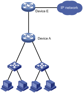
Figure 21 Network diagram for IRF configuration
Configuration considerations
· Configure the member IDs, priorities, and IRF ports on the four member switches.
· Enable enhanced IRF mode on the four member switches, and connect them as shown in Figure 21.
· Change the operating mode to IRF on the four member switches.
Configuration procedure
1. Configure Device A.
# Set the member ID to 1, and priority to 12.
<Sysname> system-view
[Sysname] irf member 1
Info: Member ID change will take effect after the switch reboots and operates in IRF mode.
[Sysname] irf priority 12
# Create IRF port 1, and bind it to physical port Ten-GigabitEthernet 3/0/2.
[Sysname] irf-port 1
[Sysname-irf-port 1] port group interface ten-gigabitethernet 3/0/2
[Sysname-irf-port 1] quit
# Create IRF port 2, and bind it to physical port Ten-GigabitEthernet 3/0/1.
[Sysname] irf-port 2
[Sysname-irf-port 2] port group interface ten-gigabitethernet 3/0/1
[Sysname-irf-port 2] quit
# Enable enhanced IRF mode.
[Sysname] irf mode enhanced
# Save the configuration to the configuration file to be used at the next startup.
[Sysname] save
The current configuration will be written to the device. Are you sure? [Y/N]:y
Please input the file name(*.cfg)[flash:/cfa0511.cfg]
(To leave the existing filename unchanged, press the enter key):
flash:/cfa0511.cfg exists, overwrite? [Y/N]:y
Validating file. Please wait.....................................
The current configuration is saved to the active main board successfully.
Configuration is saved to device successfully
# Change the operating mode to IRF.
<Sysname> system-view
[Sysname] chassis convert mode irf
The device will switch to IRF mode and reboot. You are recommended to save the current running configuration and specify the configuration file for the next startup. Continue? [Y/N]:y
Do you want to convert the content of the next startup configuration file flash:/startup.cfg to make it available in IRF mode? [Y/N]:y
Please wait...
Saving the converted configuration file to the main board succeeded.
Slot 1:
Saving the converted configuration file succeeded.
Now rebooting, please wait...
After the reboot, an IRF fabric comprising only Device A is created.
2. Configure Device B
# Set the member ID to 2, and priority to 26.
<Sysname> system-view
[Sysname] irf member 2
Info: Member ID change will take effect after the switch reboots and operates in IRF mode.
[Sysname] irf priority 26
# Create IRF port 1, and bind it to physical port Ten-GigabitEthernet 3/0/1.
[Sysname] irf-port 1
[Sysname-irf-port 1] port group interface ten-gigabitethernet 3/0/1
[Sysname-irf-port 1] quit
# Create IRF port 2, and bind it to physical port Ten-GigabitEthernet 3/0/2.
[Sysname] irf-port 2
[Sysname-irf-port 2] port group interface ten-gigabitethernet 3/0/2
[Sysname-irf-port 2] quit
# Enable enhanced IRF mode.
[Sysname] irf mode enhanced
# Save the configuration to the configuration file to be used at the next startup.
[Sysname] save
The current configuration will be written to the device. Are you sure? [Y/N]:y
Please input the file name(*.cfg)[flash:/cfa0512.cfg]
(To leave the existing filename unchanged, press the enter key):
flash:/cfa0512.cfg exists, overwrite? [Y/N]:y
Validating file. Please wait.....................................
The current configuration is saved to the active main board successfully.
Configuration is saved to device successfully
# Connect the switches as shown in Figure 21.
# Change the operating mode to IRF.
<Sysname> system-view
[Sysname] chassis convert mode irf
The device will switch to IRF mode and reboot. You are recommended to save the current running configuration and specify the configuration file for the next startup. Continue? [Y/N]:y
Do you want to convert the content of the next startup configuration file flash:/startup.cfg to make it available in IRF mode? [Y/N]:y
Please wait...
Saving the converted configuration file to the main board succeeded.
Slot 1:
Saving the converted configuration file succeeded.
Now rebooting, please wait...
After the reboot, the IRF fabric comprises Device A and Device B.
3. Configure Device C.
# Set the member ID to 3, and priority to 6.
<Sysname> system-view
[Sysname] irf member 3
Info: Member ID change will take effect after the switch reboots and operates in IRF mode.
[Sysname] irf priority 6
# Create IRF port 1, and bind it to physical port Ten-GigabitEthernet 3/0/2.
[Sysname] irf-port 1
[Sysname-irf-port 1] port group interface ten-gigabitethernet 3/0/2
[Sysname-irf-port 1] quit
# Create IRF port 2, and bind it to physical port Ten-GigabitEthernet 3/0/1.
[Sysname] irf-port 2
[Sysname-irf-port 2] port group interface ten-gigabitethernet 3/0/1
[Sysname-irf-port 2] quit
# Enable enhanced IRF mode.
[Sysname] irf mode enhanced
# Save the configuration to the configuration file to be used at the next startup.
[Sysname] save
The current configuration will be written to the device. Are you sure? [Y/N]:y
Please input the file name(*.cfg)[flash:/cfa0513.cfg]
(To leave the existing filename unchanged, press the enter key):
flash:/cfa0513.cfg exists, overwrite? [Y/N]:y
Validating file. Please wait.....................................
The current configuration is saved to the active main board successfully.
Configuration is saved to device successfully
# Connect the switches as shown in Figure 21.
# Change the operating mode to IRF.
<Sysname> system-view
[Sysname] chassis convert mode irf
The device will switch to IRF mode and reboot. You are recommended to save the current running configuration and specify the configuration file for the next startup. Continue? [Y/N]:y
Do you want to convert the content of the next startup configuration file flash:/startup.cfg to make it available in IRF mode? [Y/N]:y
Please wait...
Saving the converted configuration file to the main board succeeded.
Slot 1:
Saving the converted configuration file succeeded.
Now rebooting, please wait...
After the reboot, the IRF fabric comprises Device A, Device B, and Device C.
4. Configure Device D.
# Set the member ID to 4, and priority to 2.
<Sysname> system-view
[Sysname] irf member 4
Info: Member ID change will take effect after the switch reboots and operates in IRF mode.
[Sysname] irf priority 2
# Create IRF port 1, and bind it to physical port Ten-GigabitEthernet 3/0/1.
[Sysname] irf-port 1
[Sysname-irf-port 1] port group interface ten-gigabitethernet 3/0/1
[Sysname-irf-port 1] quit
# Create IRF port 2, and bind it to physical port Ten-GigabitEthernet 3/0/2.
[Sysname] irf-port 2
[Sysname-irf-port 2] port group interface ten-gigabitethernet 3/0/2
[Sysname-irf-port 2] quit
# Enable enhanced IRF mode.
[Sysname] irf mode enhanced
# Save the configuration to the configuration file to be used at the next startup.
[Sysname] save
The current configuration will be written to the device. Are you sure? [Y/N]:y
Please input the file name(*.cfg)[flash:/cfa0514.cfg]
(To leave the existing filename unchanged, press the enter key):
flash:/cfa0514.cfg exists, overwrite? [Y/N]:y
Validating file. Please wait.....................................
The current configuration is saved to the active main board successfully.
Configuration is saved to device successfully
# Connect the switches as shown in Figure 21.
# Change the operating mode to IRF.
<Sysname> system-view
[Sysname] chassis convert mode irf
The device will switch to IRF mode and reboot. You are recommended to save the current running configuration and specify the configuration file for the next startup. Continue? [Y/N]:y
Do you want to convert the content of the next startup configuration file flash:/startup.cfg to make it available in IRF mode? [Y/N]:y
Please wait...
Saving the converted configuration file to the main board succeeded.
Slot 1:
Saving the converted configuration file succeeded.
Now rebooting, please wait...
After the reboot, the IRF fabric comprises Device A, Device B, Device C, and Device D.
