| Title | Size | Downloads |
|---|---|---|
| H3C S5820X & S5800 Series Ethernet Switches Interface Cards User Manual-6PW106-book.pdf | 766.18 KB |
Contents
Introduction to Optional Interface Cards
100/1000Base-X SFP port status LEDs
10/100/1000Base-T auto-sensing Ethernet port LEDs
Installing and Removing an Optional Interface Card
Ordering and Installing Transceiver Modules
SFP+ transceiver module overview
SFP transceiver module overview
Installing a Transceiver Module
Introduction to Optional Interface Cards
S5820X Series and S5800 Series Ethernet Switches provide fixed ports as well as expansion slots for optional interface cards. The interface card provides an interface so that you can insert a transceiver module (SFP/SFP+) into the interface and connect it to the interface of another switch with cables.
Table 1 Optional interface card types
|
Interface card type |
Applicable to |
Description |
|
LSW1SP4P0 |
S5800 series S5820X series |
· Provides four 1/10 Gbps SFP+ fiber ports (see LSW1SP4P0). · Connects to another SFP/SFP+ port through an inserted SFP/SFP+ transceiver module and a cable. For more information about optional SFP/SFP+ transceiver modules, see SFP+ transceiver module overview and SFP transceiver module overview. · Allows device connection with SFP+ cables provided by H3C. For more information about SFP+ cables, see SFP+ cable overview. |
|
LSW1SP2P0 |
S5800 series S5820X series |
· Provides two 1/10 Gbps SFP+ fiber ports (see LSW1SP2P0). · Connects to another SFP/SFP+ port through an inserted SFP/SFP+ transceiver module and a cable. For more information about optional SFP/SFP+ transceiver modules, see SFP+ transceiver module overview and SFP transceiver module overview. · Allows device connection with SFP+ cables provided by H3C. For more information about SFP+ cables, see SFP+ cable overview. |
|
LSW1GP16P0 |
S5800 series |
· Provides sixteen 100/1000 Mbps SFP copper/fiber ports (see LSW1GP16P0). · Connects to another SFP port through an inserted SFP transceiver module and a cable. For more information about optional SFP transceiver modules, see SFP transceiver module overview. |
|
LSW1GT16P |
S5800 series |
Provides sixteen 10/100/1000 Mbps fiber Ethernet ports (see LSW1GT16P). |
|
|
NOTE: The optional interface cards described in this document are applicable to many H3C switch models. For the up-to-date information about the switch models supporting the optional interface cards, consult H3C marketing staff or technical support. |
LSW1SP4P0
Front panel
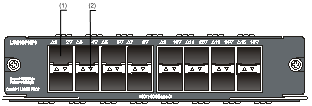
Figure 1 LSW1SP4P0 front panel

|
(1) SFP+ port |
(2) SFP+ port status LED |
SFP+ port status LEDs
Each SFP+ port on the LSW1SP4P0 front panel has its own LED, which indicates the port status, as shown in Figure 2.
Table 2 Description of SFP+ port status LEDs
|
LED |
Status |
Meaning |
|
|
SFP+ port status LED |
Rate mode |
Solid green |
The port operates at the rate of 10 Gbps; the LED is fast blinking when data is being sent and/or received on the port. |
|
Solid yellow |
The port operates at the rate of 1 Gbps only; the LED is fast blinking when data is being sent and/or received on the port. |
||
|
Blinking yellow (3 Hz) |
Power-on self text (POST) failed on the port. |
||
|
Off |
The port has not gone up. |
||
|
Duplex mode |
Solid green |
The port operates in full-duplex mode only; the LED is fast blinking when data is being sent and/or received on the port. |
|
|
Blinking yellow (3 Hz) |
POST failed on the port. |
||
|
Off |
The port has not gone up. |
||
LSW1SP2P0
Front panel
Figure 2 LSW1SP2P0 front panel

|
(1) SFP+ port |
(2) SFP+ port status LED |
SFP+ port status LEDs
Each SFP+ port on the LSW1SP2P0 front panel has its own LED, which indicates the port status. See Table 2 for LEDs description.
LSW1GP16P0
Front panel
Figure 3 LSW1GP16P0 front panel
|
(1) 100/1000Base-X SFP port |
|
|
(2) 100/1000Base-X SFP port status LED |
|
100/1000Base-X SFP port status LEDs
Each SFP port on the LSW1GP16P0 front panel has its own LED, which indicates the port status, as shown in the following table.
Table 3 Description of 100/1000Base-X SFP port status LEDs
|
LED |
Status |
Meaning |
|
|
100/1000Base-X SFP port status LED |
Rate mode |
Solid green |
The port operates at the rate of 1000 Mbps; the LED is fast blinking when data is being sent and/or received on the port. |
|
Solid yellow |
The port operates at the rate of 100 Mbps only; the LED is fast blinking when data is being sent and/or received on the port. |
||
|
Blinking yellow (3 Hz) |
POST failed on the port. |
||
|
Off |
The port has not gone up. |
||
|
Duplex mode |
Solid green |
The port operates in full-duplex mode only; the LED is fast blinking when data is being sent and/or received on the port. |
|
|
Blinking yellow (3 Hz) |
POST failed on the port. |
||
|
Off |
The port has not gone up. |
||
LSW1GT16P
Front panel
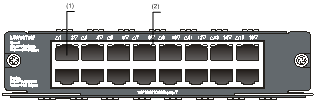
Figure 4 LSW1GT16P front panel
|
(1) 10/100/1000Base-T auto-sensing Ethernet port |
|
(2) 10/100/1000Base-T auto-sensing Ethernet port LED |
10/100/1000Base-T auto-sensing Ethernet port LEDs
Each Ethernet port on the LSW1GT16P front panel has its own LED, which indicates the port status, as shown in the following table.
Table 4 10/100/1000Base-T auto-sensing Ethernet port LEDs description
|
LED |
Status |
Meaning |
|
|
10/100/1000Base-T auto-sensing Ethernet port LED |
Rate mode |
Solid green |
The port operates at the rate of 1000 Mbps; the LED is fast blinking when data is being sent and/or received on the port. |
|
Solid yellow |
The port operates at the rate of 10/100 Mbps; the LED is fast blinking when data is being sent and/or received on the port. |
||
|
Blinking yellow (3 Hz) |
POST failed on the port. |
||
|
Off |
The port has not gone up. |
||
|
Duplex mode |
Solid green |
The port operates in full-duplex mode; the LED is fast blinking when data is being sent and/or received on the port. |
|
|
Solid yellow |
The port operates in half-duplex mode; the LED is fast blinking when data is being sent and/or received on the port. |
||
|
Blinking yellow (3 Hz) |
POST failed on the port. |
||
|
Off |
The port has not gone up. |
||
|
|
NOTE: By default, the port LED is in the rate mode. To change the rate mode to duplex mode, you can press the mode button. For more information about the mode button, see the installation manuals of different switch series. |
|
|
NOTE: · This section takes the LSW1SP4P0 interface card and the H3C S5820X-28C switch to illustrate the module installation and removal. · The installation tools are not shipped together with H3C’s Ethernet switches. You need to prepare the tools. |
The following tools are needed for installation and removal:
· Phillips screwdriver
· ESD-preventive wrist strap
Installing an Interface Card
1. Put on an ESD-preventive wrist strap and make sure that the strap is in good contact with your skin and is properly grounded.
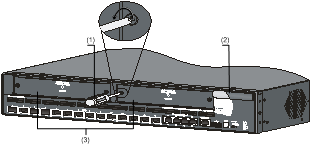
2. Loosen the mounting screws of the blank panel on the expansion slot of the switch's front panel with a Phillips screwdriver and remove the blank panel, as shown in Figure 5.
Figure 5 Remove a blank panel
|
(1) Phillips screwdriver |
(2) Switch's front panel |
|
(3) Blank panel |
|
|
|
NOTE: Keep the removed blank panel properly for future use. |
3. Unpack the interface card.
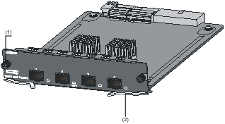
Figure 6 Interface card appearance
|
(1) Captive screw |
(2) Ejector lever |
4. Gently push the interface card in along the guide rails until the interface card is in close contact with the switch (see callout 1 in Figure 7). Then push the ejector levers at both sides inward (see callout 2 in Figure 7).
5. Fasten the captive screws with a Philips screwdriver to fix the interface card.
Figure 7 Install an interface card

Removing an Interface Card
1. Put on an ESD-preventive wrist strap and make sure that the strap is in good contact with your skin and is properly grounded.
2. Loosen the captive screws at both sides of the interface card using a Phillips screwdriver.
3. Hold the ejector levers at both sides of the interface card and push them outward (see callout 1 in Figure 8). Pull the interface card along the guides until it completely comes out of the switch chassis (see callout 2 in Figure 8).
Figure 8 Remove an interface card

|
|
NOTE: When installing or removing an optional interface card, pay attention to the following points: · Avoid touching the surface-mounted components directly with your hands. · Avoid using excessive force in the operation. · After removing an interface card, if no module is to be installed, install the blank panel as soon as possible to prevent dust and ensure the normal ventilation in the switch. |
Ordering a Transceiver Module
|
|
NOTE: The SFP transceiver modules, SFP+ transceiver modules, and SFP+ cables available for the interface cards are subject to change over time. For the most recent list of SFP transceiver modules, SFP+ transceiver modules, and SFP+ cables available for the interface cards, contact H3C Support or marketing staff. For more information about H3C SFP transceiver modules, SFP+ transceiver modules, and SFP+ cables, see H3C Transceiver Modules User Guide at www.h3c.com. |
SFP+ transceiver module overview
Table 5 shows the optional SFP+ transceiver modules for SFP+ ports on the LSW1SP4P0 or LSW1SP2P0.
Table 5 Optional SFP+ transceiver modules
|
Item |
SFP+ transceiver module |
|
SFP+ transceiver module |
SFP-XG-SX-MM850-A |
|
SFP-XG-LX220-MM1310 |
|
|
SFP-XG-LX-SM1310 |
SFP+ cable overview
Figure 9 An SFP+ cable

|
(1) Connector |
(2) Handle |
SFP+ cables support the SFP+ standard and use 10G SFP+ Cu standard cables. H3C provides the following types of SFP+ cables with various lengths, as shown in Table 6.
Table 6 Optional cables for SFP+ transceiver modules
|
SFP+ cable |
Cable length |
Description |
|
LSWM1STK |
0.65 m (2.13 ft) |
· The S5800 and S5820X series switches support the Intelligent Resilient Framework (IRF) feature, where physical connections are required among members. You can use SFP+ cables to connect the SFP+ ports. · SFP+ cables are applicable to SFP+ ports of the LSW1SP4P0 or LSW1SP2P0. · SFP+ cables are hot swappable. |
|
LSWM2STK |
1.2 m (3.94 ft) |
|
|
LSWM3STK |
3 m (9.84 ft) |
|
|
LSTM1STK |
5 m (16.40 ft) |
|
|
LSWM4STK |
10 m (32.81 ft) |
SFP transceiver module overview
Table 7 shows the optional 100/1000 Mbps SFP transceiver modules for SFP ports on the LSW1GP16P0 and the 1000 Mbps SFP transceiver modules for the SFP+ ports on the LSW1SP4P0 or LSW1SP2P0.
Table 7 Optional SFP transceiver modules
|
Item |
SFP transceiver module |
|
1000 Mbps SFP transceiver module |
SFP-GE-SX-MM850-A |
|
SFP-GE-LX-SM1310-A |
|
|
SFP-GE-LH40-SM1310 |
|
|
SFP-GE-LH40-SM1550 |
|
|
SFP-GE-LH70-SM1550 |
|
|
SFP-GE-T |
|
|
100 Mbps SFP transceiver module |
SFP-FE-SX-MM1310-A |
|
SFP-FE-LX-SM1310-A |
|
|
SFP-FE-LH40-SM1310 |
|
|
SFP-FE-LH80-SM1550 |
|
|
NOTE: The SFP+ port does not support SFP-GE-T transceiver modules. |
Installing a Transceiver Module
To avoid component damage resulting from improper installation, carefully read H3C Pluggable SFP/SFP+/XFP Transceiver Modules Installation Guide from the H3C's website before installing SFP or SFP+ transceiver modules.
After the installation, connect the cables. When the switch runs properly, check whether the module is operating properly according to the port LED status.
