| Title | Size | Downloads |
|---|---|---|
| H3C S12500 Switch Series FAQ-R1825P01-6W100-book.pdf | 1.08 MB |
- Table of Contents
H3C S12500 Switch Series (R1825P01) FAQ
|
Copyright © 2013 Hangzhou H3C Technologies Co., Ltd. All rights reserved. No part of this manual may be reproduced or transmitted in any form or by any means without prior written consent of Hangzhou H3C Technologies Co., Ltd. The information in this document is subject to change without notice. |
|
Contents
Q. What models does the H3C S12500 routing switch series include?
Q. Is power over Ethernet (PoE) supported on the switch?
Q. Does the switch support DC power supplies?
Q. Are the power supplies of the switch hot-swappable?
Q. Is it normal that the power supply fans make a lot of noise?
Q. Is it normal that a power supply has an over-low output current?
Q. Are the switching fabric modules of the switch hot-swappable?
Q. Is active/standby switchover of MPUs supported on the switch?
Q. How do I check the card serial number or manufacture information?
Q. Can the switch automatically adjust the fan speed?
Q. How is the LST2XP32 oversubscribed?
Q. Does the BootWare support forward compatibility?
Q. How do I view the system version information and operation time information?
Q. Why should I upgrade the Comware system software? How should I upgrade the software?
Q. Can I delete the Comware system software image file after the upgrade is completed?
Q. How can I empty the recycle bin?
Q. Is software patching supported?
Q. Should I remove the old patch file before installing a new patch file?
Q. What is the name of the default configuration file?
Q. What should I do before installing patches?
Q. Why doesn't the switch display the saved configuration file?
System management and maintenance.
Q. Information displayed on the console terminal is incorrect sometimes. Why?
Q. What commands should I configure to enable AUX login?
Q. How can I clear a Telnet connection?
Q. Can a Telnet user's username contain the at sign (@)?
Q. How do I format the Flash or CF card from the BootWare?
Q. How do I examine the memory of the switch before the switch starts up?
Q. Why should I wait for all LPUs to operate correctly before I save the running configuration?
Q. Can the management Ethernet interface come up without an IP address?
Q. Can the switch operate as a TFTP server?
Q. Can I power on the switch immediately after I power off the switch?
Q. How are packets arriving at the standby MPU's management Ethernet interface handled?.
Network security and attack protection
Q. What attack protection functions does the switch support?
Q. What roles can the switch play when using different SSH versions?
Q. Do the switch support local authentication before RADIUS authentication?
Q. Why can the level for the RADIUS server (the switch) only be 1 when it connects to an ACS server?
Q. Does the switch support local authentication when HWTACACS authentication fails?
Q. Can the switch be connected to a TACACS server that runs third-party TACACS server software?
Q. Must the server type for the switch configured with a RADIUS scheme be set to extended?
Q. How do I set the user privilege level assigned to users for logging in to the user interface?
Q. How do I prevent gateway spoofing when the switch acts as a gateway?
Q. Which kinds of OAA modules are supported on the switch?
Q. What is the maximum number of bits of a port count?
Q. Does the switch support jumbo frames?
Q. Are the MAC address tables the same for different cards of the switch?
Q. Can frames be correctly forwarded when the MAC address learning limit is set to 0?
Q. Why is a MAC address learned into multiple VLANs?
Q. How is the traffic load-shared for link aggregation on the switch?
Q. Does the switch support configuring static MAC address entries on an aggregate interface?
Q. Does the switch support RRPP after link aggregation is configured on the switch?
Q. What fields are displayed in the output transceiver module optical power information?
Q. How is the port rate percentage calculated?
Q. What restrictions and guidelines should I follow when I configure loop detection?
Q. What STP protocols are supported?
Q. What STP protocols are available in the industry?
Q. How are ARP entries and MAC address entries handled when the STP topology changes?
Q. When does an MSTP port send TC BPDUs?
Q. Why are MSTP port states wrong when MSTP configuration is correct on the switch?
Q. Do RSTP and MSTP have TCN BPDUs?
Q. Why are ports on a Cisco device down when MSTP is disabled on the connected ports of the switch?
Q. What STP modes are interoperable between the switch and the third-party devices?
Q. How can I interoperate the switch with a third-party device in MSTP mode?
Q. What are the precautions for configuring digest snooping?
Q. Does the switch support configuring an IP address for a physical port?
Q. Does the switch support configuring a secondary IP address for a VLAN interface?
Q. Is the secondary IP address still valid when the primary IP address is removed?
Q. What is the MAC address of a VLAN interface used for?
Q. Does the switch send trap messages when the maximum size of the ARP table is reached?
Q. How is ECMP load sharing implemented on the switch?
Q. Does the switch support weighted ECMP load sharing?
Q. How does VRRP tracking function?
Q. How does the switch handle an ICMP ping packet whose size exceeds 1500 bytes?
Q. Is the sending interval of ICMP ping packets configurable on the switch?
Q. What are the restrictions and guidelines for URPF configuration?
Q. What releases for the switch support IPv6 on the VLAN interface of a super VLAN?
Q. What are the restrictions for connecting the switch to a Juniper MX900 device through VPLS?
Q. How do I filter LSPs triggered by routes with non-32 bit masks?
Q. Can the BVLAN and the CVLAN for a PBBN be the same?
Q. Does the switch support configuring blackhole routes?
Q. What are the preferences of different routing protocols?
Q. What are the possible reasons for the OSPF CONFIG ERROR trap?
Q. Why is the LS ACK: BAD ack count a non-zero value when I display OSPF error information?
Q. Why are OSPF router ID conflict logs generated?
Q. Is IGMP supported on the switch?
Q. What IP multicast protocols are supported on the switch?
Q. Is static RP configuration supported on the switch?
Q. Are static multicast routes supported on the switch?
Q. How do I deny multicast packets from an illegal multicast source?
Q. Is multicast group filtering supported on the switch?
Q. Does the link-aggregation load-sharing mode command enable load sharing of multicast traffic?
Q. Can the VRRP virtual IP address be the next hop for the switch to reach the multicast source?
Q. Is auto-RP supported on the switch?
Q. Does the switch support multiboard traffic and port mirroring?
Q. Does the switch support multichassis traffic and port mirroring?
Q. What restrictions and guidelines should I follow when I configure port mirroring on the switch?
Q. How many destination ports can I configure for traffic mirroring on the switch?
Q. How many destination ports can I configure for port mirroring on the switch?
Q. Can I configure both traffic mirroring and port mirroring on the switch?
Q. Does packet filtering configured on the switch affect the port mirroring function?
Q. Does the switch support multichassis port mirroring and traffic redirection to a port?
Q. Does the switch support a QoS policy for outgoing traffic?
Q. What are the priorities of QoS policies configured on the switch?
Q. What's the match order of ACL rules on the switch?
Q. What are the differences when the permit or deny statement is used in different applications?
Q. What's the order in which ACL rules are restored after a card is restarted?
Q. Can the match criteria configured on the switch match Layer 2 or Layer 3 packets?
Q. Does the switch support packet filtering?
Q. How do I configure packet filtering on the switch?
Q. Does the switch support traffic policing for traffic flows on multiple ports (aggregate CAR)?
Q. Does the switch support traffic redirection?
Q. Does the switch support strong or weak PBR for traffic forwarding?
Q. Why can a tracert response be received from the switch after the switch is configured with PBR?
Q. How do I clear traffic statistics on the switch?
Q. Can an ACL match ICMP packets encapsulated with PPPoE on the switch?
Q. Does the switch trust the priorities of a packet by default?
Q. Does the switch functioning as a P device in an MPLS network trust the EXP value of a packet?
Q. Can WRR be configured together with GTS?
Q. Does the switch support collecting traffic statistics of a VLAN interface?
Q. What benefits does QinQ provide?
Q. What are the differences between basic QinQ and selective QinQ?
Q. Can QinQ add another tier of VLAN tag to a double-tagged customer frame?
Q. Why can't the if-match customer-vlan-id command match the CVLAN tag for selective QinQ?
Q. How does selective QinQ obtain the 802.1p priority value for an SVLAN tag?
Q. Can the 802.1p priority in a CVLAN tag be modified?
Q. Does the switch learn MAC addresses to the SVLAN or CVLAN on a QinQ port?
Q. Can an H3C S12500 switch form an IRF fabric with other series devices?
Q. How many chassis can an H3C S12500 IRF fabric have?
Q. Are there any special requirements for connecting IRF member chassis?
Q. What topologies does IRF support?
Q. Does an IRF fabric support multichassis Ethernet link aggregation?
Q. Can I set up an IRF connection that has multiple links?
Q. Can IRF member chassis use duplicate member IDs?
Q. Are there any software feature consistency requirements for a successful IRF setup?
Q. Why can't I configure a port as a Layer 3 Ethernet interface?
Q. Why can't I disable enhanced IRF?
Q. Can I run LACP MAD on any Ethernet link aggregation?
Q. Why doesn't BFD MAD take effect when the spanning tree feature is enabled globally in IRF mode?
Q. Why are ports that were shut down by MAD still down after an IRF merge?
Q. Why do the subordinate chassis reboot automatically upon IRF merge?
Q. Why can't data traffic be forwarded at the wire speed on IRF links?
H3C S12500 Switch Series (R1825P01) FAQ
Hardware
This section contains the most frequently asked questions about the switch hardware.
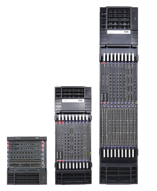
Q. What models does the H3C S12500 routing switch series include?
A. The H3C S12500 Routing Switch Series includes H3C S12504, H3C S12508, and H3C S12518.
· An H3C S12504 switch has slot 0 and slot 1 for main processing units (MPUs), and has slots 2 through 5 for line processing units (LPUs).
· An H3C S12508 switch has slot 0 and slot 1 for MPUs, and has slots 2 through 9 for LPUs.
· An H3C S12518 switch has slot 0 and slot 1 for MPUs, and has slots 2 through 19 for LPUs.
H3C S12504, H3C S12508, and H3C S12518 switches are illustrated from left to right in Figure 1.
Q. Is power over Ethernet (PoE) supported on the switch?
A. No. The switch does not support PoE.
Q. Does the switch support DC power supplies?
A. Yes. The switch supports both AC and DC power supplies.
Q. Are the power supplies of the switch hot-swappable?
A. Yes. The power supplies of the switch are hot-swappable. As long as the power provided by the operating power supplies meets the requirements, the switch runs correctly.
Q. Is it normal that the power supply fans make a lot of noise?
A. An operating power supply adjusts its fan speed based on its temperature. It is normal that the fans operate at a higher speed for a period of time under the following conditions:
· For an AC power supply:
? Hard switching is performed. When the current of an AC power supply is less than 5 A, the power supply uses hard switching. When hard switching is performed, a large amount of heat is produced, causing high fan speed. When the current is greater than 5 A, the power supply uses soft switching. When soft switching is performed, a small amount of heat is produced, resulting in low fan speed.
? The power supply is under heavy load, producing a large amount of heat.
· For a DC power supply:
The power supply is under a heavy load, producing a large amount of heat.
In these conditions, the power supply does not generate an alarm. If the power supply is faulty, an alarm is generated.
Q. Is it normal that a power supply has an over-low output current?
A. It is normal that a power supply's output current is an over-low value or 0 when the system power load is less than 25% of the system power capacity. When the load is increased or one or more power supplies are removed, the power supply monitoring software will automatically adjust the output current of each available power supply and the output current value will go up accordingly.
If a power supply's output current remains at about 0 when the system power load increases or one or more power supplies are removed, the power supply might be faulty.
Q. Are the switching fabric modules of the switch hot-swappable?
A. Yes. The switching fabric modules of the switch are hot-swappable.
Q. Is active/standby switchover of MPUs supported on the switch?
A. Yes. The switch supports active/standby switchover of the MPUs. The standby MPU can automatically take over the responsibility of the failed active MPU, ensuring uninterrupted services. For a successful active/standby switchover, make sure the software versions on the active and standby MPUs are consistent. You can also use the slave switchover command to manually perform an active and standby switchover:
In standalone mode:
[Sysname]slave switchover
Caution!!! Confirm to switch slave to master? [Y/N]:y
In IRF mode:
<Sysname>reboot chassis <id> slot <id>
Before manually performing an active and standby switchover, make sure the configuration of the active MPU has been backed up to the standby MPU. If the manual switchover takes place during the backup process, the switchover fails and the system displays an error message. You can use the display switchover state command to view the status of the standby MPU.
<Sysname> display switchover state
Q. How do I check the card serial number or manufacture information?
A. Use the display device manuinfo command on the switch. The following is a sample command output.
<Sysname>display device manuinfo
Chassis self
Slot 0:
DEVICE_NAME : LST1GT48LEC1
DEVICE_SERIAL_NUMBER : 210231A85N0099000041
MAC_ADDRESS : NONE
MANUFACTURING_DATE : 2012-10-21
VENDOR_NAME : H3C
Slot 2:
DEVICE_NAME : LST1GT48LEC1
DEVICE_SERIAL_NUMBER : 210231A85N0099000041
MAC_ADDRESS : NONE
MANUFACTURING_DATE : 2012-10-21
VENDOR_NAME : H3C
Q. Can the switch automatically adjust the fan speed?
A. Yes. The switch can automatically adjust the fan speed based on the temperature in the chassis. You can use the display fan verbose command to display detailed information about fans. The following is a sample command output.
<Sysname>display fan verbose
Fan-tray verbose state on chassis 2:
Fan-tray 1:
Software version: 105
Hardware version: Ver.A
CPLD version: 002
Fan number: 12
Temperature: 37 °C
High temperature alarm threshold: 60 °C
Low speed alarm threshold: 750 rpm
Fan Status Speed(rpm)
--- ---------- ----------
1 normal 4320
2 normal 4440
3 normal 4380
4 normal 4740
5 normal 4080
6 normal 4440
7 normal 4320
8 normal 4320
9 normal 4380
10 normal 4560
11 normal 4500
12 normal 4500
Fan-tray 2:
Software version: 105
Hardware version: Ver.A
CPLD version: 002
Fan number: 12
Temperature: 37 °C
High temperature alarm threshold: 60 °C
Low speed alarm threshold: 750 rpm
Fan Status Speed(rpm)
--- ---------- ----------
1 normal 4320
2 normal 4440
3 normal 4380
4 normal 4740
5 normal 4080
6 normal 4440
7 normal 4320
8 normal 4320
9 normal 4380
10 normal 4560
11 normal 4500
12 normal 4500
Q. How is the LST2XP32 oversubscribed?
The LST2XP32 has a capacity of 80 Gbps and provides thirty-two 10 GE ports. It is oversubscribed at a ratio of 4:1. Every four ports comprise an oversubscription group and share a 10 G bandwidth, as follows:
· Ports 1, 5, 9, and 13
· Ports 2, 6, 10, and 14
· Ports 3, 7, 11, and 15
· Ports 4, 8, 12, and 16
· Ports 17, 21, 25, and 29
· Ports 18, 22, 26, and 30
· Ports 19, 23, 27, and 31
· Ports 20, 24, 28, and 32
Software
This section contains the most frequently asked questions about the switch software.
Q. Does the BootWare support forward compatibility?
A. Yes. The BootWare supports forward compatibility. After a software upgrade, you can roll back the Comware system software without rolling back the BootWare.
Q. How do I view the system version information and operation time information?
A. Use the display version command. This command displays information about the current BootWare version, Comware system software version, and system operation time.
Q. Why should I upgrade the Comware system software? How should I upgrade the software?
A. H3C continually improves the Comware system software to meet customer requirements and solve problems. By upgrading the Comware system software, you can fix existing software bugs, and obtain more features and functions, optimized applications, and higher device performance, availability, and attack protection capability.
To make sure the configuration file can operate correctly after an upgrade, do the following:
1. Before the upgrade, use the save command to save the running configuration, and use FTP to save a copy of the file to a PC.
2. After the upgrade is completed, examine that all cards are operating correctly, use the save command to save the running configuration, and use FTP to save a copy of the file to a PC.
3. Compare the two configuration files and reconfigure the commands that are missing.
H3C recommends that you use a file comparing tool, such as Beyond Compare. The configuration files usually contain a large quantity of commands.
This procedure applies to upgrades from one Comware V5 version to another Comware V5 version and upgrades from one Comware V7 version to another Comware V7 version. For information about how to upgrade the software from Comware V5 to Comware V7, see H3C S12500 Comware V5-V7 Migration Guide.
Q. Can I delete the Comware system software image file after the upgrade is completed?
A. No. The file contains the software images for MPUs and the software images for LPUs. MPUs and LPUs read these images during startup.
Q. Can I view deleted files?
A. Yes if the files were deleted by a delete command without the /unreserved option. A delete command with the /unreserved option permanently deletes files. A delete command without the /unreserved option moves commands to the recycle bin.
To view the commands in the recycle bin, use the dir /all command. The name of a file in the recycle bin is placed in brackets ([ ]).
You can use the undelete command to restore commands from the recycle bin.
Q. How can I empty the recycle bin?
A. Use the reset recycle-bin command. If a file in the recycle bin is corrupt, use the reset recycle-bin command with the force keyword to delete the file.
Q. Is software patching supported?
A. Yes. The switch supports software patching.
Q. Should I remove the old patch file before installing a new patch file?
A. Yes. You must remove the old patch file from the storage media manually before installing a new patch file. A new patch file contains the patches in the old patch file.
Q. What is the name of the default configuration file?
A. The name of the default configuration file is flash:/config.cfg.
Q. What should I do before installing patches?
A. Before installing patches, do the following:
· Make sure the patch image file is saved to the same type of storage medium (flash or CF card) on the MPUs.
· Make sure the patch image files on the MPUs are located in the same directory.
· Specify the path of the patch image file for the patch file location argument.
Q. Why doesn't the switch display the saved configuration file?
A. The device does not display the saved configuration file at the first startup:
<Sysname>display startup
MainBoard:
Startup saved-configuration file: NULL
Next startup saved-configuration file: flash:/config.cfg
SlaveBoard:
Startup saved-configuration file: NULL
Next startup saved-configuration file: flash:/config.cfg
System management and maintenance
This section contains the most frequently asked questions about system management and maintenance.
Q. Information displayed on the console terminal is incorrect sometimes. Why?
A. If nothing is displayed on the console terminal, examine the following:
· Whether the power system is operating correctly.
· Whether the MPUs are operating correctly.
· Whether the console cable is connected to the console port correctly.
If no problem is found, the reason might be one of the following:
· The access port specified for the terminal is different from the port to which the console cable is connected.
· Settings on the configuration terminal are incorrect.
· The cable has a problem.
If garbled characters are displayed on the terminal, settings on the configuration terminal might be incorrect.
The correct terminal settings are as follows:
· Bits per second—9600 bps
· Flow control—None
· Parity—None
· Stop bits—1
· Data bits—8
· Terminal display type—VT100
If you are running the terminal software SecureCRT, you must deselect the DTR/DSR option and RTS/CTS option for flow control. By default, the RTS/CTS option is selected for flow control.
Q. What commands should I configure to enable AUX login?
A. You can configure the following commands:
[Sysname] user-interface aux 0
[Sysname-ui-aux0] authentication-mode none
[Sysname-ui-aux0] user privilege level 3
Q. How can I clear a Telnet connection?
A. Use the free user-interface vty number command in user view.
Q. Can a Telnet user's username contain the at sign (@)?
A. The username of a Telnet user that is configured on the switch cannot contain the at (@) sign.
Q. I cleared the packet statistics on an interface by using the reset counters interface command. Why does the MIB browser show that the error packet count is still the same?
A. The MIB browser shows the values of the hardware counters. The reset counters interface command does not reset the hardware counters. This command clears only the statistics calculated by software.
Q. How do I format the Flash or CF card from the BootWare?
A. Do the following while the device is starting up:
1. Press Ctrl+B as prompted to enter the BootWare menu.
2. Select the storage medium to be formatted (Flash by default) and press Ctrl+F:
=============<EXTEND-BOOTWARE MENU>===============
|<1> Boot System
|<2> Enter Serial SubMenu
|<3> Enter Ethernet SubMenu
|<4> File Control
|<5> Restore to Factory Default Configuration |
|<6> BootWare Operation Menu
|<7> Clear Super Password
|<8> Storage Device Operation
|<9> Product Special Operation
|<0> Reboot
============================================================================
Ctrl+Z: Access EXTEND-ASSISTANT MENU
Ctrl+F: Format File System
Enter your choice(0-9): 8
==============================<DEVICE CONTROL>==============================
|<1> Display All Available Nonvolatile Storage Device(s) |
|<2> Set The Operating Device
|<3> Set The Default Boot Device
|<0> Exit To Main Menu
============================================================================
Enter your choice(0-3): 2
Please set the operating device:
============================================================================
|Note:the operating device is cfa0 |
|NO. Device Name File System Total Size Available Space
|1 flash VFS 132909056 132892672
|2 cfa0 FAT 1044549632 282378240
|0 Exit
============================================================================
Enter your choice(0-2):1
Set the operation device successful!
==============================<DEVICE CONTROL>==============================
|<1> Display All Available Nonvolatile Storage Device(s) |
|<2> Set The Operating Device
|<3> Set The Default Boot Device
|<0> Exit To Main Menu
============================================================================
Enter your choice(0-3): 0
===========================<EXTEND-BOOTWARE MENU>===========================
|<1> Boot System
|<2> Enter Serial SubMenu
|<3> Enter Ethernet SubMenu
|<4> File Control
|<5> Restore to Factory Default Configuration |
|<6> BootWare Operation Menu
|<7> Clear Super Password
|<8> Storage Device Operation
|<9> Product Special Operation
|<0> Reboot
============================================================================
Ctrl+Z: Access EXTEND-ASSISTANT MENU
Ctrl+F: Format File System
Enter your choice(0-9):
Warning:All files on flash will be lost! Are you sure to format? [Y/N]
Q. How do I examine the memory of the switch before the switch starts up?
A. Power on the switch and press Ctrl+T or Ctrl+Y as prompted.
Press Ctrl+T to start the 5-step memory test procedure:
%Jun 4 10:47:23:092 2013 DEVM/5/SYSTEM_REBOOT: System is rebooting now.
DDR2 SDRAM test successful.
Press Ctrl+T to start five-step full RAM test...
Press Ctrl+Y to start nine-step full RAM test...
Running five-step RAM test...
This operation may take several minutes. Please wait...
DDR2 SDRAM dataline testing... [ PASS ]
DDR2 SDRAM addressline testing... [ PASS ]
Five-step RAM test succeeded.
System is starting...
Press Ctrl+Y to start the 9-step memory test procedure:
DDR2 SDRAM test successful.
Starting Nine-Step ram test.
DDR2 SDRAM dataline testing... [ PASS ]
DDR2 SDRAM addressline testing... [ PASS ]
DDR2 SDRAM unit testing... [ PASS ]
Nine-Step ram test successful.
System is starting...
Booting Normal Extend BootWare
The Extend BootWare is self-decompressing.....................Done!
Q. Will the switch relearn MAC address entries, ARP entries, and FIB entries after an active/standby switchover?
A. No, the switch does not relearn MAC address entries and ARP entries, and it differs for FIB entries depending on whether or not GR and NSR are configured for the routing protocol:
· MAC address entries are saved on LPUs. A switchover does not affect MAC entries or data forwarding based on the entries.
· ARP entries are backed up on the standby MPU. A switchover does not affect ARP entries or data forwarding based on the entries.
· FIB entries are also backed up on the standby MPU:
? If GR or NSR is configured for the routing protocol, the routing protocol continues to operate after a switchover, and the switch has to relearn routes. However, data forwarding based on the existing entries is not affected.
? If both GR and NSR are not configured for the routing protocol, a switchover brings the routing protocol down and causes the FIB entries to be lost. Data forwarding is stopped and the switch must learn FIB entries again.
Q. Why should I wait for all LPUs to operate correctly before I save the running configuration?
A. The configuration is saved on the Flash. During startup, the switch configures LPUs by loading the configuration to memory. If you execute the save command before the process is completed, the incomplete configuration in memory will be saved to the Flash to replace the complete configuration, resulting in configuration loss.
Q. Can the management Ethernet interface come up without an IP address?
A. Yes. The interface can come up as long as the Layer 2 link is up. In addition, flow control is performed on the interface by software, and excessive packets arriving at the interface cannot affect system operation.
Q. I was using TFTP to transfer data from the switch. Why did the transfer fail when the amount of transferred data reached about 32 MB?
A. This problem is caused by the TFTP server. Some TFTP servers have a limit of 32 MB on a transferred data block. When the amount of transferred data for the block reaches approximately 32 MB, the TFTP server stops requesting data transfer. If you experience this problem, please change the TFTP server software.
Q. Can the switch operate as a TFTP server?
A. No.
Q. Can I power on the switch immediately after I power off the switch?
A. H3C recommends that you follow these steps to power cycle the device:
1. Power off the device by turning off the power switches one by one.
2. Wait 3 to 5 seconds so electricity is completely released.
3. Power on the device by turning on the power switches one by one.
Q. How are packets arriving at the standby MPU's management Ethernet interface handled?
A. A packet arriving at a management Ethernet interface is always forwarded to the CPU. Then, the software examines whether or not the MPU that holds the management Ethernet interface is the standby MPU:
· If it is the standby MPU, the switch discards the packet.
· If it is the active MPU, the switch proceeds to process the packet.
The CPU on an MPU processes up to 2000 packets per second.
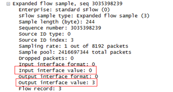
Q. Why does the Input interface value or Output interface value field in an sFlow packet have a value of 0?
A. A sample packet in the inbound direction does not carry the outbound packet count. A sample packet in the outbound direction does not carry the inbound packet count.
Figure 2 Sample in the inbound direction
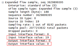
Figure 3 Sample in the outbound direction
Network security and attack protection
This section contains the most frequently asked questions about network security and attack protection.
Q. What attack protection functions does the switch support?
A. The switch supports the link layer attack protections, ARP attack protections, network layer attack protections, and transport layer attack protections, as shown in Table 1.
Table 1 Attack protection types
|
Attack protection types |
Description |
|
|
Link layer attack protection |
MAC address attack protection |
Prevents the attack of packets with different source MAC addresses or VLANs by configuring the maximum number of MAC addresses that an interface can learn. |
|
STP packet attack protection |
Provides protection measures such as BPDU guard, root guard, loop guard, TC-BPDU guard, and STP status confusion protection. |
|
|
ARP attack protection |
ARP source suppression |
Prevents IP attack packets from fixed sources. |
|
ARP black hole routing |
Prevents IP attack packets from sources that are not fixed. |
|
|
ARP active acknowledgement |
Prevents user spoofing. |
|
|
Source MAC-based ARP attack detection |
Prevents ARP packet attacks from the same source MAC. |
|
|
ARP packet source MAC consistency check |
Prevents attacks from ARP packets whose source MAC address in the Ethernet header is different from the sender MAC address in the message body. |
|
|
Network layer attack protection |
uRPF check |
Protects a network against source spoofing attacks. |
|
ICMP attack protection |
Prevents ICMP fragments attacks by disabling forwarding ICMP fragments. |
|
|
TTL attack protection |
Prevents an attack by disabling sending ICMP time exceeded messages. |
|
|
Transport layer attack protection |
SYN flood attack protection |
After receiving a TCP connection request, the server directly returns a SYN ACK message, instead of establishing a half-open TCP connection. |
|
Naptha attack protection |
The device periodically checks the number of TCP connections in each state. If it detects that the number of TCP connections in a state exceeds the maximum number, it will accelerate the aging of TCP connections in this state. |
|
Q. What roles can the switch play when using different SSH versions?
A. Table 2 describes roles for the switch according to SSH version.
Table 2 Switch roles and SSH versions
|
Version/Feature |
SSH1 |
SSH2 |
|
S12500 |
Acts as the server. |
Acts as the server and the client. |
Q. Do the switch support local authentication before RADIUS authentication?
A. No. Local authentication can be performed only when no response is received from the RADIUS server.
Q. Why cannot a user log in to an ACS authentication server through a console port when the switch uses RADIUS authentication?
A. The user can log in to an ACS server through a console port only when you deselect the login-service option for the ACS server configuration.
Q. Why can the level for the RADIUS server (the switch) only be 1 when it connects to an ACS server?
A. The symptom might occur when one of the following conditions takes place:
· The server type for the switch is not set to extended.
· The 2011/002 private attributes for the ACS server are not complete.
· The login-service attribute for the ACS server is not configured.
Q. Does the switch support local authentication when HWTACACS authentication fails?
A. The switch supports local authentication when the HWTACACS server is disconnected.
The switch does not support local authentication when the HWTACACS server operates correctly with an authentication failure due to a wrong username or a wrong password.
To enable local authentication, specify the local keyword in the authentication default command. The command configures the default authentication mode for an ISP domain to use an HWTACACS scheme and use local authentication as the backup. The following commands must be executed:
· domain isp-name
· authentication default hwtacacs-scheme hwtacacs-scheme-name local
Q. Can the switch be connected to a TACACS server that runs third-party TACACS server software?
A. As long as the TACACS server is configured with the standard RADIUS protocol, the switch can be connected to the server. The servers include ACS servers from Cisco and TACACS servers open to public (for example, free TACACS servers).
Q. Must the server type for the switch configured with a RADIUS scheme be set to extended?
A. Yes. The server type must be set to extended for RADIUS scheme configuration when you need to do one of the following:
· Specify an accessory path instead of using the default path Flash.
· Assign a privilege level to a Telnet user instead of assigning the default privilege level of 0.
Q. Does the reply from a RADIUS server include the login-service option after the authentication succeeds?
A. It depends on the server. The login-service option does not matter to the switch, but the switch needs to process the service-type option.
Q. How do I set the user privilege level assigned to users for logging in to the user interface?
A. You can set the user privilege level by executing the user privilege level level command in user interface view or by executing the authorization-attribute level command in local user view.
If the switch acts as a HWTACACS server, set the user privilege level on the switch.
Q. What is the relationship between the levels authorized by an S12500 HWTACACS server and the levels authorized by a Cisco ACS server?
A. The levels have the following relationships:
· The levels 0 to 2 authorized by an H3C S12500 HWTACACS server correspond to the levels 0 to 2 authorized by a Cisco ACS server.
· The levels 3 to 16 authorized by a Cisco ACS server correspond to the level 3 authorized by an H3C S12500 HWTACACS server.
Q. Which one of the user level configured in VTY user interface and the user level configured on a RADIUS server or a TACACS server prevails for a Telnet user?
A. The user level configured on a RADIUS server or a TACACS server prevails. Both the default levels are 0.
For example, if the user level 3 is configured in VTY user interface, and no user level is configured on the server, the user level 0 takes effect for the Telnet user.
If no user level or any user level is configured in VTY user interface, and user level 3 is configured on the server, user level 3 takes effect for the Telnet user.
The user level configured in VTY user interface takes effect only the authentication-mode one command or the password command is executed.
Q. How do I prevent gateway spoofing when the switch acts as a gateway?
A. When receiving an ARP packet from a device that acts as a gateway, the switch (the gateway) sends a gratuitous ARP packet to modify the spoofed ARP entries. If a large number of attack packets exist, the switch detects the incoming interface of the attack packets, captures the packets to obtain packet information, and sets an ACL rule to filter the attack packets.
Q. Which kinds of OAA modules are supported on the switch?
A. The switch can use OAA modules to provide firewall, NetStream, load balancing, IPS, and ACG features.
Network access
This section contains the most frequently asked questions about network access.
Q. What is the maximum number of bits of a port count?
A. On the switch, the port count can be up to 64 bits, and the port count will be reset after it exceeds 64 bits.
Q. Can the interface of the switch suppress unicast packets, broadcast packets, and multicast packets at the same time?
A. The interface of a switch can suppress unicast packets, broadcast packets, and multicast packets at the same time. However, the suppression must be configured for unicast packets, broadcast packets, and multicast packets, respectively, with the same suppression threshold as follows:
[Sysname-GigabitEthernet1/5/0/24] unicast-suppression [pps | kbps] xxx
[Sysname-GigabitEthernet1/5/0/24] multicast-suppression [pps | kbps] xxx
[Sysname-GigabitEthernet1/5/0/24]broadcast-suppression [pps | kbps] xxx
Q. What are the meanings of the error packet fields for input and output packets in the output from the display interface command?
A. Table 3 and Table 4 describe the meanings of the error packet fields for input and output packets in the output from the display interface command.
Table 3 Error packet fields for input packets
|
Field |
Description |
|
Runts |
Number of inbound frames shorter than 64 bytes, in correct format, and containing valid CRCs. |
|
Giants |
Number of inbound frames larger than the maximum frame length supported on the interface and containing valid CRCs. |
|
Throttles |
Number of inbound frames shorter than 64 bytes and containing CRC errors. |
|
CRC |
Total number of inbound frames that had a normal length, but contained CRC errors. |
|
Frame |
Total number of inbound frames that contained unknown errors. |
|
Overruns |
Number of packets dropped because the input rate of the port exceeded the queuing capability. This problem occurs when the network is congested. |
|
Aborts |
Number of inbound frames with input description errors. The type of error frames will not occur on the H3C S12500 switches. |
Table 4 Error packet fields for output packets
|
Field |
Description |
|
Underruns |
Number of packets dropped because the output rate of the interface exceeded the output queuing capability. The type of error frames will not occur on the H3C S12500 switches. |
|
buffer failures |
Number of packets dropped because the transmit buffer of the interface ran low. The type of error frames will not occur on the H3C S12500 switches. |
|
Aborts |
Packets that failed to be forwarded at the MAC layer due to network congestion. |
|
Deferred |
Number of frames that the interface operating in half duplex mode deferred to transmit because of detected collisions. |
|
Collisions |
Number of frames that the interface stopped transmitting because Ethernet collisions were detected during transmission. |
|
late collisions |
Number of frames that the interface deferred to transmit and were buffered at the MAC layer. The type of error frames will not occur on the H3C S12500 switches. |
|
lost carrier |
Number of carrier losses during transmission. The type of error frames will not occur on the H3C S12500 switches. |
|
no carrier |
Number of times that the port failed to detect the carrier when attempting to send frames. The type of error frames will not occur on the H3C S12500 switches. |
The output packet errors seldom occur. Most packets errors are input packet errors.
· When error frames of the runts, giants, throttles, CRC, and frame types are received, you must verify whether the peer device or the transmission link in between fails.
· When overruns error frames are received, you must verify whether the link bandwidth of the local end is enough.
Q. Does the switch support jumbo frames?
A. The switch supports setting the maximum jumbo frame size, which is a maximum of 9216 bytes. On LST1XP16LEB1 and LST1XP16LEC1 cards, the maximum jumbo frame size is a maximum of 8168 bytes.
Q. Are the MAC address tables the same for different cards of the switch?
A. The MAC address tables for different cards might be different. The MAC address table of a card contains the MAC address entries of VLANs to which the ports belong. When a VLAN spans across multiple cards, the MAC address entries must be synchronized between cards.
Q. How long is the aging timer for dynamic MAC address entries? How are the dynamic MAC address entries aged?
A. The aging time for dynamic MAC address entries is 5 minutes by default. The aging time can be modified by using the mac-address timer aging command.
When a data flow enters a port, the MAC address of the data flow is dynamically learned. When the data flow continues to send traffic, the aging time of the MAC address entry continues to be refreshed, and the MAC address entry will not be aged. When the data flow stops sending traffic, the MAC address entry is aged after the aging time expires.
The aging time of a dynamic MAC address entry cannot be queried.
Q. Can frames be correctly forwarded when the MAC address learning limit is set to 0?
A. When the MAC address learning limit is set to 0 on a port, the port does not learn MAC addresses, and frames are broadcast in VLANs by default. If you do not want to forward the frames, you can use the mac-address max-mac-count disable-forwarding command to configure the device not to forward frames with unknown source MAC addresses after the MAC address learning limit is reached.
Q. Why does a port still have MAC address entries after the mac-address max-mac-count 0 command is configured on the port?
A. These MAC address entries are learned before MAC address learning was disabled. When MAC address learning is disabled, the software does not actively delete these MAC address entries. Instead, the software waits for these MAC address entries to age out.
Q. Why is a MAC address learned into multiple VLANs?
A. The switch learns MAC address entries in the MAC+VLAN method. When multiple VLANs receive packets with the same MAC address, all these VLANs will learn the MAC address.
Q. How is the traffic load-shared for link aggregation on the switch?
A. You can use the link-aggregation load-sharing mode command to change the load sharing criteria and flexibly load-share the traffic across the member ports of aggregation groups. The system uses the hash algorithm to calculate the load sharing criteria. The algorithm can calculate the load sharing criteria based on the MPLS label, service port number, IP address, MAC address, ingress port, and any combination of the fields.
Q. Does the switch support configuring static MAC address entries on an aggregate interface?
A. The switch supports configuring static MAC address entries on an aggregate interface.
Q. Does the switch support RRPP after link aggregation is configured on the switch?
A. Yes.
Q. Does DLDP take effect when one fiber is connected in case that two fibers of a link are both disconnected?
A. When both ends of a link are down, DLDP neighborship cannot be established. As a result, DLDP does not take effect.
Q. What fields are displayed in the output transceiver module optical power information?
A. The switch supports diagnosing transceiver modules. When the Rx or Tx optical power of a transceiver module is not within the normal range, the ports might go down. In this case, you can verify that the transceiver module models at both end match and whether the link is operating correctly. The optical power fields are as follows:
· RX power is high!
· RX power is low!
· RX power is normal!
· TX power is high!
· TX power is low!
Q. How is the port rate percentage calculated?
A. The port rate percentage is the ratio of the actual traffic to the total port bandwidth and describes the actual port bandwidth usage. When you calculate the port rate percentage, the inter-frame gap and the preamble must be added as follows:
(ulActualSpeed + 20 (preamble + inter-frame gap) * ulPktSpeed) * 8/ulRatedSpeed
· ulActualSpeed—Rate in kbps (the field in red) in the output.
· ulPktSpeed—Rate in pps (the field in blue) in the output.
· ulRatedSpeed—Port rate. For example, the port rate of a 10-GE port is 10000000000 bps.
[Sysname-Ten-GigabitEthernet5/0/2]display interface Te5/0/2
Ten-GigabitEthernet5/0/2 current state: DOWN
IP Packet Frame Type: PKTFMT_ETHNT_2, Hardware Address: 00e0-fc00-0000
Description: Ten-GigabitEthernet5/0/2 Interface
Loopback is not set
……
Peak value of input: 0 bytes/sec, at 2000-04-26 12:00:32
Peak value of output: 0 bytes/sec, at 2000-04-26 12:00:32
Last 300 seconds input: 0 packets/sec 0 bytes/sec 0%
Last 300 seconds output: 0 packets/sec 0 bytes/sec 0%
Input (total): 0 packets, 0 bytes
- unicasts, - broadcasts, - multicasts
Input (normal): 0 packets, 0 bytes
0 unicasts, 0 broadcasts, 0 multicasts
Input: 0 input errors, 0 runts, 0 giants, 0 throttles
0 CRC, 0 frame, 0 overruns, - aborts
- ignored, - parity errors
Output (total): 0 packets, 0 bytes
- unicasts, - broadcasts, - multicasts, - pauses
Output (normal): 0 packets, 0 bytes
0 unicasts, 0 broadcasts, 0 multicasts, 0 pauses
Output: 0 output errors, - underruns, - buffer failures
0 aborts, 0 deferred, 0 collisions, 0 late collisions
- lost carrier, - no carrier
Q. How are the Selected ports determined when GE ports and 10-GE ports are added to an aggregation group?
A. Link aggregation has dynamic and static modes. The following section describes how the Selected ports are determined in static mode and dynamic mode when the ports have the same aggregation priority.
· Static aggregation
The candidate ports are sorted in the following order: Full duplex/high speed > Full duplex/low speed > Half duplex/high speed > Half duplex/low speed. The candidate port at the top and with the same class-two configurations as the aggregate interface is chosen as the reference port. As a result, a 10-GE port will be selected as the reference port, the 10-GE port becomes a Selected port, and the GE port becomes an Unselected port.. For more information about class-two configurations, see Layer 2—LAN Switching Configuration Guide.
· Dynamic aggregation
Dynamic aggregation chooses the port with the smallest port number as the reference port. The port number is not the port number used for configuration. Instead, the port number is a 16-bit index. To view the port number of a port, use the display link-aggregation member-port command. The port number determines which port becomes a Selected port.
[Sysname-Ten-GigabitEthernet15/0/1]dis link-aggregation member-port Ten-GigabitEther
net 15/0/1
Flags: A -- LACP_Activity, B -- LACP_Timeout, C -- Aggregation,
D -- Synchronization, E -- Collecting, F -- Distributing,
G -- Defaulted, H -- Expired
Ten-GigabitEthernet15/0/1:
Aggregation Interface: Bridge-Aggregation5
Local:
Port Number: 105
Port Priority: 32768
Oper-Key: 4
Flag: {AC}
Remote:
System ID: 0x8000, 3822-d659-7c00
Port Number: 112
Port Priority: 32768
Oper-Key: 1
Flag: {AC}
Received LACP Packets: 3 packet(s)
Illegal: 0 packet(s)
Sent LACP Packets: 3 packet(s)
|
|
NOTE: IRF physical ports are assigned to and removed from aggregation groups by the switch, and GE ports and 10-GE ports are not differentiated. When IRF physical ports include both GE ports and 10-GE ports, make sure the traffic passing through any IRF physical port does not exceed the rate of 1 Gbps. Otherwise, packet loss might occur when traffic passes through GE ports. |
Q. Why is the peer port down and the local port not down when the port of an S12500 switch is connected to the port of another device?
A. When fiber GE ports are connected and the local port is manually configured with a speed and duplex mode, the local port can go up only if the port can receive fiber signals. When the speed and duplex mode of the local port are autonegotiated, the local port goes down when the peer port goes down.
When fiber 10-GE ports of two S12500 switches are connected, the MAC layer will negotiate the port status. If one end detects local faults, the port will go down and send remote faults to notify the remote end. When the remote end detects remote faults, the remote port will go down.
When the port of an S12500 switch connects to the port of a device other than an S12500 switch, the local port does not go down if both of the following are true:
· The remote port is down but sends out fiber signals correctly.
· The remote port does not send remote faults.
Q. What restrictions and guidelines should I follow when I configure loop detection?
A. When you configure loop detection, follow these restrictions and guidelines:
· Configure loop detection for only the suspicious VLANs or the VLANs where loops might occur because many devices are attached. To save system resources, H3C recommends not configuring loop detection for all VLANs. If link redundancy and backup are planned for the links, you can configure STP rather than loop detection.
· Loop detection and STP do not conflict with each other. However, it is a good practice to configure STP separately.
· Typically, H3C recommends that you use STP to detect the loops in the network. When troubleshooting the network, you can use loop detection to rapidly locate the looped ports.
· When you use loopback detection together with STP, do not set the loop protection action to shutdown. Otherwise, the ports shut down by loop detection might affect the actions of STP.
· If loop detection has been enabled for a VLAN, do not configure port mirroring on the ports in the VLAN. Otherwise, the loop detection function might fail.
· When the loopback-detection action none command is configured, the system generates logs and traps on detecting loops, but the system does not perform actions to eliminate the loops. If loops are not eliminated for a long time, the loop detection frames might increase the broadcast traffic within the loops.
· Within the VLANs with loop detection enabled, a port is shut down to eliminate loops when the following are true:
? The port receive a packet with the source MAC address as the local bridge MAC address
? The loopback protection action is set to shutdown.
If you use STP in this situation, STP shuts down a small number of ports to eliminate loops in the network.
· A port shut down by the loop detection action stays down until you use the undo shutdown command to manually bring up the port. This mechanism might cause traffic interruption on the ports. When the loop detection feature is used, H3C recommends that you manually bring up the looped ports after eliminating the loops.
· In Release 1825 and later versions, the MAC address moving notification function is supported. This function can also detect possible Layer 2 loops and does not have influence on the traffic.
Spanning tree protocols
This section contains the most frequently asked questions about spanning tree protocols.
Q. What STP protocols are supported?
A. The switch supports the following STP protocols:
· STP.
· RSTP—Compatible with STP.
· MSTP—The default one. MSTP is compatible with STP and RSTP.
· PVST—Allows each VLAN to build a separate spanning tree. PVST improves link bandwidth usage in network environments where multiple VLANs exist.
Q. What STP protocols are available in the industry?
A. Table 5 shows a complete list of STP protocols.
|
Protocol name |
Standard |
Destination MAC |
Advantages |
Disadvantages |
|
Spanning Tree Protocol (STP) |
IEEE 802.1d |
01-80-c2-00-00-00 |
Eliminates loops, prevents broadcast storms, and backs up links. |
Network convergence is slower. |
|
Rapid Spanning Tree Protocol (RSTP) |
IEEE 802.1w |
01-80-c2-00-00-00 |
· Compared with STP, RSTP improves the network convergence speed. · Alternate port, backup port, edge port, and point-to-point link are introduced. |
· An RSTP network maintains only one spanning tree. A small topology change might affect the whole network. · Loops exist on trunk ports. · Link efficiency is reduced by blocking links. |
|
Per VLAN Spanning Tree (PVST) |
Cisco |
01-00-0c-cc-cc-cd |
Allows each VLAN to build a separate spanning tree. |
· A large amount of PVST BPDUs are sent, which might reduce the system performance. · Incompatible with STP and RSTP. |
|
Per VLAN Spanning Tree+ (PVST+) |
Cisco |
01-00-0c-cc-cc-cd |
PVST+ runs STP in VLAN 1 and PVST in other VLANs, which allows CST and PVST exist in the same network. |
Abundant PVST+ BPDUs are sent, which might reduce the system performance. |
|
Multi-Instance Spanning Tree Protocol (MISTP) |
Cisco |
01-80-c2-00-00-00 |
· Maps a range of VLANs to an instance and allows each instance to build a separate spanning tree. · Lower CPU usage. |
Incompatible with STP, RSTP, and PVST. |
|
Multi-Instance Spanning Tree Protocol -- Per VLAN Spanning Tree+ (MISTP-PVST+) |
Cisco |
01-80-c2-00-00-00 |
Intermediate mode of MISTP and PVST+. This mode is compatible with MISTP and PVST+. |
Proprietary protocol, not popular. |
|
Multiple Spanning Tree (MST) |
Cisco |
01-80-c2-00-00-00 |
· Maps a range of VLANs to an instance and allows each instance to build a separate spanning tree. · Lower CPU usage. · Rapid port role and state transition. · Compatible with STP, RSTP, and PVST+. · Sends Cisco-defined BPDUs. |
Incompatible with the MSTP BPDU format defined by IEEE 802.1s. |
|
Multiple Spanning Tree Protocol (MSTP) |
IEEE 802.1s |
01-80-c2-00-00-00 |
· Maps a range of VLANs to an instance and allows each instance to build a separate spanning tree. · Lower CPU usage. · Rapid port role and state transition. · Compatible with STP, RSTP, and PVST+. · Sends standard BPDUs. |
N/A |
Q. How are ARP entries and MAC address entries handled when the STP topology changes?
A. When the STP topology changes, the MAC address entries on the changed ports are removed.
The ARP entries of these MAC addresses are set as invalid entries, and ARP requests are sent out. If the corresponding ARP response reaches the device, the ARP entry status is updated. Otherwise, the ARP entry is removed.
If a new MAC address is learned after the STP topology changes, the ARP entry related to the MAC address is also updated.
Q. When does an MSTP port send TC BPDUs?
A. According to IEEE 802.1s MSTP, a port generates TC BPDUs when all of the following requirements are met:
· The port is not an edge port.
· The port role transits from alternate, backup, or disabled to root, designated, or master.
· The port state transits from discarding or learning to forwarding.
A port running STP or RSTP also generates TC BPDUs when the above requirements are met.
The TC BPDU generation might result from STP recalculation. STP recalculation is caused by the following reasons:
· Device failure or recovery.
· Link state change.
· Device configuration change.
· Abnormal BPDU sending or receiving.
Q. Why are MSTP port states wrong when MSTP configuration is correct on the switch?
A. When the switch is operating in MSTP mode, its ports can operate in STP compatibility mode or MSTP mode. If a port is connected to another switch enabled with STP, the port transits to STP compatibility mode automatically. However, when the connected switch is changed to one enabled with MSTP, the port cannot transit back to MSTP mode automatically. In this case, MSTP calculation errors occur. To make MSTP operate correctly, use the stp mcheck command in interface view.
Q. Do RSTP and MSTP have TCN BPDUs?
A. RSTP does not have TCN BPDUs. When network topology changes, RSTP sets the TC bit to 1 in configuration BPDUs and sends the BPDUs to the root port.
Q. Why are ports on a Cisco device down when MSTP is disabled on the connected ports of the switch?
A. The switch will transparently transmit the STP BPDUs sent by the Cisco device. The Cisco device considers that it has received BPDUs sent by itself and a loop exists, so it shuts down the port receiving the BPDUs.
Q. What STP modes are interoperable between the switch and the third-party devices?
A. The switch can interoperate with Cisco devices in MSTP mode and in instance 0 of the PVST+ mode. The switch cannot interoperate with Cisco devices in PVST mode.
Q. How can I interoperate the switch with a third-party device in MSTP mode?
A. In MSTP mode, the switch and its connected Cisco device each considers itself as the regional root, even if they have the same region configuration. They cannot be in the same region.
To make the switch interoperate with the Cisco device in MSTP mode, execute the stp config-digest-snooping command on the ports connected to the Cisco device in interface view.
The switch sends and receives standard-format MSTP BPDUs, while the Cisco device might send and receive MSTP BPDUs in a different format.
· If the Cisco device sends non-standard-format BPDUs, execute the stp compliance auto command on the switch to configure the ports to recognize the MSTP BPDU format automatically and determine the format of MSTP BPDUs to send.
· If the Cisco device sends and receives standard-format MSTP BPDUs, execute the stp compliance dot1s command on the switch. The switch will send and receive standard-format MSTP BPDUs on the ports.
Q. What are the precautions for configuring digest snooping?
A. When you configure digest snooping, follow these restrictions and guidelines:
· Enable digest snooping on all the ports that connect the switch to the third-party devices in the same MST region. The switch and the third-party devices must have the same MST region configuration. Otherwise, inconsistent VLAN-to-instance mapping on neighbor devices can cause broadcast storms.
· To avoid loops, do not enable digest snooping on MST region edge ports.
· To make digest snooping take effect, you must enable digest snooping both globally and on associated ports.
· Enable digest snooping on all associated ports first and then globally.
· When digest snooping is enabled globally, do not modify the MST region configuration. To modify the region configuration, disable digest snooping on all devices in the MST region first. Otherwise, inconsistent VLAN-to-instance mapping on neighbor devices can cause broadcast storms.
· When digest snooping is enabled globally and on a port, the switch saves the most recent configuration digest received by the port. The configuration digest takes effect even if digest snooping is disabled on the port.
IP forwarding services
This section contains the most frequently asked questions about IP forwarding services.
Q. Does the switch support configuring an IP address for a physical port?
A. You can configure an IP address for a physical Ethernet port on the switch. Before the configuration, you must use the port link-mode route command to configure the Ethernet port to operate in Layer 3 mode. By default, an Ethernet port operates in Layer 2 mode.
Q. Does the switch support configuring a secondary IP address for a VLAN interface?
A. Yes. You can configure a secondary IP address for the VLAN interface of the switch. The secondary IP address has a similar function as the primary IP address. The secondary IP address cannot be used for multicast. The users on the network segment to which the secondary IP address belongs cannot receive any multicast packets or establish OSPF neighbor relationship.
In addition, you can configure secondary IP addresses for any Layer 3 interface, including Layer 3 Ethernet interfaces (subinterfaces) and Layer 3 aggregation interfaces (subinterfaces).
Q. Is the secondary IP address still valid when the primary IP address is removed?
A. No. To delete the primary IP address of a VLAN interface or a Layer 3 interface, you must delete all of its secondary IP addresses first. Otherwise, the primary address cannot be deleted.
[Sysname-Vlan-interface1]undo ip address 1.1.1.1 24
Warning: Must delete sub address before deleting primary address!
Q. What is the MAC address of a VLAN interface used for?
A. When an Ethernet interface operates in bridge mode (configured with the port link-mode bridge command), the switch examines the MAC address of a packet received on the interface. If the MAC address of the packet matches the MAC address of the VLAN interface, the switch forwards the packet at Layer 3 or sends the packet through MPLS network. If not, the switch forwards the packet at Layer 2.
Q. Does the switch send trap messages when the maximum size of the ARP table is reached?
A. No. But the following log is generated:
%Oct 5 09:53:33:655 2010 H3C DRVL3/3/DRVL3_LOG_EMERG: No enough resource!
Q. How is ECMP load sharing implemented on the switch?
A. The switch supports ECMP load sharing based on destination MAC address, source MAC address, source IP address, destination IP address, destination TCP/UDP port, and source TCP/UDP port. You can configure ECMP load sharing as required, and you can configure it in the same way link aggregation load sharing is configured. For more information, see Layer 2—LAN Switching Configuration Guide.
When you use the link-aggregation load-sharing mode command to configure the load sharing criteria, follow these restrictions and guidelines:
· All criteria except mpls-label1, mpls-label2, mpls-label3, and per-packet apply to ECMP load sharing for unicast traffic.
· Per-packet load sharing applies to Ethernet link aggregation, but not to ECMP.
Q. Does the switch support weighted ECMP load sharing?
A. No.
Q. How does VRRP tracking function?
A. You can configure a VRRP group to track the status of an interface on the master. If the interface is down or removed, the priority of the master automatically decreases by a specific value, and the backup with higher priority takes over. The switch can only track Layer 3 Ethernet interfaces, VLAN interfaces, and Layer 3 aggregate interfaces. If a VLAN interface is tracked, the priority of the switch is not decreased as long as one of the physical ports in the VLAN is up.
Q. Does the VRRP module of the switch support associating a track entry with a physical port on the master?
A. Yes. You can associate a track entry with a VRRP group to monitor the status of a physical port and change the priority of the master in the VRRP group.
Q. In the FIB table, when a route obtained from the routing table conflicts with a host route obtained from the ARP table, which route has a higher priority for packet forwarding?
A. The route with a 32-bit mask obtained from the routing table has a higher priority.
Q. Does the unauthorized DHCP server detection function take effect when the switch operates as a Layer 2 device?
A. No. You must use the DHCP module to provide the unauthorized DHCP server detection function. If the switch operates as a Layer 2 device, the DHCP requests received cannot be delivered to the CPU for processing, so the switch cannot check for unauthorized DHCP servers.
Q. How does the switch handle an ICMP ping packet whose size exceeds 1500 bytes?
A. When sending an ICMP echo request whose size (including the IP header) exceeds 1500 bytes (the default MTU value), the switch fragments the packet. If the Don't fragment flag is set, the packet fails to be sent out.
When receiving an ICMP echo request exceeding 1500 bytes, the switch, if configured with jumbo frame support, can process the request and respond with an ICMP echo reply. The switch also fragments the reply if its size exceeds 1500 bytes.
Q. Is the sending interval of ICMP ping packets configurable on the switch?
A. Upon receiving an ICMP echo request, the CPU of the switch responds with an ICMP echo reply.
Upon receiving an ICMP echo reply, the switch sends the next request by default. If no reply is received, the switch sends the next request when the aging timer expires. By default, the aging timer is 2 seconds.
If you specify the -m interval option in the ping command, the switch sends the next ICMP echo request at the specified interval after receiving an ICMP echo reply.
Q. What are the restrictions and guidelines for URPF configuration?
A. When configuring URPF, follow these restrictions and guidelines:
· URPF is only configurable in VLAN interface view.
· The switch does not support URPF check by using an ECMP route that has more than eight next hops.
· Do not configure URPF on a private VLAN interface bound to a VPN instance that has no reserved VLAN configured when the system operates in standard mode.
· URPF check takes effect on only incoming packets on the interface.
Q. How do I set an MTU value?
A. MTU value setting takes effect on IPv4 software forwarding, but not on hardware forwarding. IPv6 supports setting MTU values on both software and hardware forwarding, and you can set a maximum of 14 MTU values.
You can set the MTU value for IPv4 and IPv6 as follows:
[Sysname-Vlan-interface30]mtu ?
INTEGER<64-9198> MTU value
[Sysname-Vlan-interface30]ipv6 mtu ?
INTEGER<1280-9198> MTU (bytes)
Q. I configure an IPv6 address on a trunk port configured on the internal interface of the OAA module on the switch. Why do I get a prompt that an IP address conflict occurs?
A. When you configure an IPv6 address on the VLAN interface, the VLAN interface sends an NS message for Duplicate Address Detection (DAD). Upon receiving the NS message, the front subcard sends it to the rear subcard for processing. The rear subcard processes the message and sends it back to the CPU. Upon receiving the same NS message, the CPU considers that an NA message is received and an IP address conflict occurs.
Q. What releases for the switch support IPv6 on the VLAN interface of a super VLAN?
A. The 17XX and 18XX releases support IPv6 on the VLAN interface of a super VLAN.
MPLS
This section contains the most frequently asked questions about MPLS.
Q. What are the restrictions for connecting the switch to a Juniper MX900 device through VPLS?
A. The restrictions are as follows:
· Set the PW encapsulation type to bgp-vpls.
· Set the initial site ID to 1.
· Configure the port at the public side as a trunk port when the switch is directly connected to the Juniper MX900 device.
Q. How do I filter LSPs triggered by routes with non-32 bit masks?
A. You can configure label acceptance policies on the switch to achieve the purpose. A label acceptance policy uses an IP prefix list to control the label mappings received from a peer. This example uses LDP peer 1.1.1.9:
[Sysname]ip ip-prefix host index 10 permit 0.0.0.0 0 greater-equal 32 less-equal 32
[Sysname]mpls ldp
[Sysname-mpls-ldp]accept-label peer 1.1.1.9 ip-prefix host
After the configuration, the switch accepts only the FEC-label mappings containing 32-bit prefixes from LDP peer 1.1.1.9.
To remove the label acceptance policy and accept non-32 bit prefixes from the LDP peer, execute the undo accept-label command and then the reset mpls ldp peer command. More LSPs will be created as a result, using up the LSP resources on the switch.
Q. Can the BVLAN and the CVLAN for a PBBN be the same?
A. Do not configure a VLAN as both the BVLAN and the CVLAN. Otherwise, the customer network will receive non-PBB broadcasts with the BVLAN tag from the public network.
For example, when both the BVLAN and the CVLAN are VLAN 20, a broadcast frame is processed as follows:
· When receiving a non-PBB broadcast with VLAN tag 20 from the PNP, the BEB forwards the frame to the CNP that matches packets with outer VLAN ID 20. The CNP broadcasts the frame in the customer network.
· When receiving a PBB broadcast with VLAN tag 20 from the PNP, the BEB de-encapsulates the frame, restores it to a standard Ethernet frame, and forwards the frame out of the corresponding CNP to the customer network according to the VLAN tag that is carried in the de-encapsulated frame.
H3C recommends that you configure the B-VLAN and the CVLAN as different VLANs, and configure the CNP on the BEB to deny frames from the BVLAN.
IP routing
This section contains the most frequently asked questions about IP routing.
Q. Does the switch support configuring blackhole routes?
A. Yes. A blackhole route is a static route whose output interface is Null 0. The switch discards the matching packets without sending ICMP messages to notify the source host. To prevent IP attacks, you can configure blackhole routes to discard packets destined for specific destinations. The following example shows how to configure a blackhole route:
<Sysname>system-view
[Sysname]ip route-static 1.1.1.1 32 null 0 preference 1
Q. Is the OSPF cost of an interface on the switch relevant to the rate of the corresponding Layer 2 Ethernet interface?
A. No. The OSPF cost is configured on a VLAN interface. The default OSPF cost is 10.
Q. What are the preferences of different routing protocols?
A. Routing protocols, including static routing, each have a preference by default. If they find multiple routes to the same destination, the router selects the route with the highest preference as the optimal route. The preference of a direct route is always 0 and cannot be changed. You can configure a preference for each static route and each dynamic routing protocol. Table 6 lists the route types and default preferences. The smaller the value, the higher the preference.
Table 6 Route types and default route preferences
|
Route type |
Preference |
|
Direct route |
0 |
|
OSPF |
10 |
|
IS-IS |
15 |
|
Static route |
60 |
|
RIP |
100 |
|
OSPF ASE |
150 |
|
OSPF NSSA |
150 |
|
IBGP |
255 |
|
EBGP |
255 |
|
Unknown (route from an untrusted source) |
256 |
Q. What are the possible reasons for the OSPF CONFIG ERROR trap?
A. The following configuration errors cause the switch to output the OSPF CONFIG ERROR trap:
· The switch is configured with an IP address on the same network segment as a device that is in the same VLAN as the switch but in a different area.
· The virtual link configuration is performed on the peer device but not on the switch. When the switch receives packets sent from the peer device through the virtual link, the switch outputs the OSPF CONFIG ERROR trap.
Q. Why is the LS ACK: BAD ack count a non-zero value when I display OSPF error information?
A. For example, in daisy chain networking Switch A—Switch B—Switch C (Switch A, Switch B, and Switch C are called A, B, and C in this example):
1. A sends LSA-1 to B. B stores a copy of LSA-1 in the retransmission list, and B forwards LSA-1 to C. When receiving LSA-1, C uses the LSA to update its LSDB. Before C sends an LSAck packet to acknowledge LSA-1, the next step occurs.
2. A updates LSA-1 and sends the updated LSA to B. B stores a copy of the updated LSA in the retransmission list, and B forwards the updated LSA to C. The copy of updated LSA replaces the copy of LSA-1 because LSA-1 has not been acknowledged.
3. Before receiving the updated LSA, C sends an LSAck packet to acknowledge LSA-1.
4. B examines the LSAck packet by using the LSA in the retransmission list and finds that they do not match. This error increases the count of LS ACK: BAD ack by one.
Q. When the next hop of a static route becomes invalid, route recursion is performed and the blackhole route applies. How do I resolve this problem?
A. The problem might occur if the following configurations are performed:
ip route-static 110.75.4.0 23 Null0 preference 240 description HZCM4_T18_VIP_BGP_Advertise
ip route-static 110.75.4.0 24 110.75.0.234 description HZCM4_T18_VIP
ip route-static 110.75.4.0 24 110.75.0.254 preference 240 description HZCM4_T18_VIP
When the next hop 110.75.0.234 becomes invalid, the output interface to 110.75.4.0 becomes Null 0:
dis fib 110.75.4.0
Destination count: 1 FIB entry count: 1
Flag:
U:Useable G:Gateway H:Host B:Blackhole D:Dynamic S:Static
R:Relay
Destination/Mask Nexthop Flag OutInterface InnerLabel Token
110.75.4.0/24 110.75.0.234 USB NULL0 Null Invalid
To avoid route recursion, specify an output interface for the static route with next hop 110.75.0.254:
ip route-static 110.75.4.0 24 vlan-interface 100 110.75.0.254 preference 240 description HZCM4_T18_VIP
When the next hop 110.75.0.234 becomes invalid, the static route with next hop 110.75.0.254 applies.
Q. Why are OSPF router ID conflict logs generated?
A. If an OSPF router ID conflict or network flapping occurs, the switch frequently generates OSPF router ID conflict logs such as:
#Sep 14 11:28:58:993 2012 H3C OSPF/6/ORIGINATE_LSA: OSPF TrapID1.3.6.1.2.1.14.16.2.12<ospfOriginateLsa>: Originate new LSA AreaId 0.0.0.0 LsdbType 1 LsdbLsid 11.11.11.11 LsdbRouterId 11.11.11.11 Router 11.11.11.11.
Trap format:
Originate new LSA AreaId [STRING] LsdbType [STRING] LsdbLsid [STRING] LsdbRouterId [STRING] Router [STRING] .
Variable fields:
· $1: Area ID
· $2: LSDB type
· $3: LSDB link state ID
· $4: LSDB router ID
· $5: Router ID
If the switch and its directly connected peer device have the same router ID, the switch generates the OSPF router ID conflict log such as:
#Sep 17 10:59:49:558 2012 H3C OSPF/4/IF_BAD_RX: OSPF TrapID1.3.6.1.2.1.14.16.2.8
<ospfIfRxBadPacket>: Non-virtual Interface 10.10.30.2 index 0 Router 11.11.11.11 received error packet from 10.10.30.1 PacketType 1.
Trap format:
Non-virtual Interface [STRING] index 0 Router [STRING] received error packet from [STRING] PacketType 1.
Variable fields:
· $1: Interface ID
· $2: Router ID
· $3: Peer interface ID
The trap shows that the switch receives error packets of type 1 (hello packets).
IP multicast
This section contains the most frequently asked questions about IP multicast.
Q. Is IGMP supported on the switch?
A. Yes. The switch supports IGMPv1, IGMPv2, and IGMPv3.
Q. What IP multicast protocols are supported on the switch?
A. The switch supports IGMP, IGMP snooping, PIM-DM, PIM-SM, MSDP, and MBGP.
Q. Is static RP configuration supported on the switch?
A. Yes. You can use the static-rp rp-address [ acl-number ] [ preferred ] [ bidir ] command to configure a static RP in PIM view and apply the ACL rule to filter multicast groups to which the RP is designated.
When you configure the static RP, follow these restrictions and guidelines:
· Up to 10 static RPs are supported on each switch.
· All switches in the PIM domain must be configured with the static-rp command and the static RP addresses must be the same.
· If the BSR mechanism is used to dynamically elect the RP for the network, the configured static RP does not take effect.
Q. Are static multicast routes supported on the switch?
A. Yes. You can use static multicast routes to change or create reverse path forwarding (RPF) routes.
Q. How do I deny multicast packets from an illegal multicast source?
A. You can configure ACL rules to permit multicast packets only from legal sources. For example, to establish a multicast forwarding entry with the multicast source address 99.100.100.4 and the multicast group address 225.1.1.1, you can perform the following configurations:
1. Configure an ACL rule.
[Sysname] acl number 3000
[Sysname-acl-adv-3000] rule 0 permit ip source 99.100.100.4 0 destination 225.1.1.1 0
[Sysname-acl-adv-3000] rule 1 deny ip
2. Use the source-policy command in PIM view to reference the configured ACL rule.
[Sysname-pim] source-policy 3000
Q. Is multicast group filtering supported on the switch?
A. Yes. You can use the igmp-snooping group-policy acl-number [ vlan vlan-list ] command on a Layer 2 Ethernet port or Layer 2 aggregation interface to filter multicast groups.
When you configure a multicast group filter, follow these restrictions and guidelines:
· A host joins only the multicast groups that match the permit statement in the specified ACL. If the specified ACL does not exist or the ACL does not have any rules configured, the host cannot join any multicast groups.
· The multicast group filtering takes effect on all ports in the specified VLAN.
· The multicast group filtering does not take effect on static member ports.
Q. How does the switch forward a multicast packet to the receiver after the multicast packet fails RPF check?
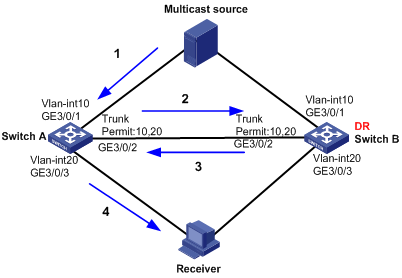
A. As shown in Figure 4, because Switch B acts as the DR, a multicast packet from the source is forwarded along the path to the receiver: Switch A to Switch B and then to Switch A. Because the RPF interface on Switch A for the multicast packet is VLAN-interface 10, the multicast packet will fail the RPF check and be dropped.
To solve this problem, use one of the following methods:
· Make sure VLAN-interface 20 on Switch A has a higher IP address than the IP address of VLAN-interface 20 on Switch B, so Switch A can win the DR election. Multicast packets from the source are forwarded to the receiver directly by Switch A.
The VRRP virtual IP addresses configured on the VLAN-interface 20 on Switch A and VLAN-interface 20 on Switch B do not participate in the DR election.
· Perform the following configurations on Switch A:
a. Use the multicast rpf-fail-pkt bridging command in system view to enable forwarding of multicast packets that have failed RPF checks.
b. Use the multicast forwarding on-demand in VLAN view of VLAN 20 to enable the multicast forwarding on-demand function in this VLAN.
After the configuration, multicast packets that fail RPF checks are multicast in VLAN 20.
Q. The RPF check fails after the MSDP peer switchover in inter-domain multicast routing. What are the possible reasons?
A. If the configuration for the static RPF peer is not correct, such as an incorrect filtering policy for the static RPF peer, the RPF check fails.
The RPF check might fail in a correct network. When a packet is received on a non-RPF interface, RPF check fails if loops exist between MSDP peers.
Q. Does the link-aggregation load-sharing mode command enable load sharing of multicast traffic?
A. No.
Q. Can the VRRP virtual IP address be the next hop for the switch to reach the multicast source?
A. No.
Q. Is auto-RP supported on the switch?
A. After the switch is enabled with auto-RP, it receives automatic RP announcement and discovery messages, but it cannot advertise RP information.
QACL
This section contains the most frequently asked questions about QACL.
Q. Does the switch support multiboard traffic and port mirroring?
A. Yes.
Q. Does the switch support multichassis traffic and port mirroring?
A. The switch does not support multichassis port mirroring. In IRF mode, the source port of port mirroring must be on the same IRF member device as the destination port or the ports of the destination VLAN.
The switch does not support multichassis traffic mirroring. In IRF mode, the source port of traffic mirroring must be on the same IRF member device as the destination port, the ports of the destination VLAN, or the CPU. However, the switch supports multichassis traffic mirroring that mirrors traffic to the port of an OAA module or an aggregate interface on another IRF member device. (When two aggregate group member ports are on different IRF member devices, traffic is mirrored to the local aggregate group member port but not the remote one. This is the case even if the local aggregate group member port goes down.)
Q. What restrictions and guidelines should I follow when I configure port mirroring on the switch?
A. Follow these restrictions and guidelines when you configure port mirroring on the switch:
· Packets from multiple source ports can be mirrored to the same destination port (monitor port).
· A source port and its destination port can be located on different LPUs.
· A port cannot function as a source port and monitor port at a time for different mirroring groups.
Q. How many destination ports can I configure for traffic mirroring on the switch?
A. The switch supports mirroring only inbound traffic to common ports, aggregate interfaces, VLANs, and the CPU. Traffic mirroring to the CPU uses one destination port resource regardless of whether traffic mirroring to the CPU is configured. You can configure a maximum of six destination ports in total for traffic mirroring to common ports, aggregate interfaces, and VLANs on the switch.
The LST1XP16LEB1, LST1XP16LEC1, and LST1XP16LEC2 cards do not support mirroring traffic to VLANs.
Q. How many destination ports can I configure for port mirroring on the switch?
A. The limits on the number of destination ports for port mirroring in one direction are described as follows:
· A 48-port GE card supports two destination ports, with one destination port for every 24 ports in their sequential order.
· Except LST1XP32REB1, LST1XP32REC1, LST2XP32REC2, LST1XP16LEB1, LST1XP16LEC1, and LST1XP16LEC2 cards, a 10 GE card supports one destination port for every two 10 GE ports in their sequential order.
· An LST1XP32REB1, LST1XP32REC1, or LST2XP32REC2 card supports four destination ports.
· An LST1XP16LEB1, LST1XP16LEC1, or LST1XP16LEC2 card supports eight destination ports, with one destination port for every two odd-numbered ports and one destination port for every two even-numbered ports.
Q. Can I configure both traffic mirroring and port mirroring on the switch?
A. Yes. However, traffic mirroring and port mirroring cannot use the same destination port.
Q. Does packet filtering configured on the switch affect the port mirroring function?
A. No. All packets received on a port are mirrored to the destination port regardless of the packet filtering function.
Q. In which situation will the prompt "Error: Failed to configure port mirroring due to hardware unsupported!" be displayed when I configure the mirroring function?
A. In IRF mode, the switch does not support multichassis port mirroring. This prompt is displayed when you try to configure the source and destination ports on different IRF member devices.
Q. Does the switch support multichassis port mirroring and traffic redirection to a port?
A. In IRF mode, the switch does not support mirroring or redirecting traffic to a common destination port on a different IRF member device. The switch supports using traffic mirroring to mirror inbound traffic to the interface of an OAA module on a different IRF member device.
Q. Does the switch support a QoS policy for outgoing traffic?
A. Yes. On the switch, a QoS policy for outgoing traffic supports only the packet filtering, traffic policing, traffic accounting, colored and uncolored dscp/dot1p/exp priority marking, and the outer VLAN tag adding actions.
Q. What are the priorities of QoS policies configured on the switch?
A. Global QoS policies, interface QoS policies, and VLAN QoS policies are in descending order of priority.
Q. What restrictions and guidelines should I follow when I configure VLAN QoS policies on the switch?
A. VLAN QoS policies are used to match packets only when the packets fail to match global QoS policies and interface QoS policies. When you apply a QoS policy to VLANs, the QoS policy is applied to the specified VLANs on all interface cards. If the hardware resources of an interface card are insufficient, the QoS policy fails to be applied to the VLANs on the interface card.
The system does not automatically roll back the QoS policy configuration already applied to the main processing unit or other interface cards. To ensure consistency, use the undo qos vlan-policy vlan command to manually remove the QoS policy configuration applied to them. Similarly, if VLAN QoS policies on an interface card cannot be updated because of insufficient hardware resources, you also need to use the undo qos vlan-policy vlan command to manually remove the QoS policy configuration applied to the main processing unit or other interface cards to ensure consistency.
Q. What restrictions and guidelines should I follow when I configure global QoS policies on the switch?
A. Global QoS policies are used to match packets preferentially. After packets match a global QoS policy, interface QoS policies and VLAN QoS policies do not take effect.
Global QoS policies are applied to all interface cards. If the hardware resources of an interface card are insufficient, the QoS policy fails to be applied to the interface card. The system does not automatically roll back the QoS policy configuration already applied to the main processing unit or other interface cards. To ensure consistency, use the undo qos apply policy global command to manually remove the QoS policy configuration applied to them. Similarly, if global QoS policies on an interface card cannot be updated because of insufficient hardware resources, you also need to use the undo qos apply policy global command to manually remove the QoS policy configuration applied to the main processing unit or other interface cards.
Q. What's the match order of ACL rules on the switch?
A. The following ACL match orders are available on the switch:
· config—Sorts ACL rules in ascending order of rule ID. A rule with a lower ID is matched before a rule with a higher ID. This match order is the default order.
· auto—Sorts ACL rules in depth-first order. Depth-first order makes sure any subset of a rule is always matched before the rule.
The match order of user-defined ACLs can only be config.
The ACL rules are displayed in the actual match order in the display acl acl-number command output.
[Sysname]display acl 3000
Advanced ACL 3000, named -none-, 3 rules, match-order is auto,
ACL's step is 5
rule 10 permit tcp source 10.11.0.0 0.0.255.255
rule 5 permit ip source 10.11.113.0 0.0.0.255
rule 0 permit ip
Q. What are the differences when the permit or deny statement is used in different applications?
A. The differences when the permit or deny statement is used in different applications are as follows:
· When an ACL is used for QoS traffic classification, the deny statement disables QoS from executing the behavior associated with the class, and the permit statement enables QoS to execute the behavior associated with the class.
· When an ACL is used for packet filtering, packets matching the deny statement are dropped, and packets that do not match the deny statement are allowed to pass through.
· When an ACL is used for policy-based routing (PBR), the ACL is used to identify traffic, and the permit or deny action does not take effect.
· When an ACL is used for other applications, packets that do not match the permit statement are denied.
Q. Why cannot a device on an external network ping the VLAN interface of the switch configured with PBR?
A. ICMP ping packets need to be forwarded to the CPU for processing based on the FIB. The packets matching an ACL will be forwarded to the next hop based on PBR. Therefore, the packets cannot be forwarded to the CPU and the ping fails.
H3C recommends that you configure packet filtering to reference an ACL rule with the permit statement to forward packets with the destination MAC address as the VLAN interface MAC address to the CPU.
Q. What's the order in which ACL rules are restored after a card is restarted?
A. The order in which ACL rules are displayed in the display acl acl-number command output is the order in which the ACL rules are restored after a card is restarted.
Q. Can the match criteria configured on the switch match Layer 2 or Layer 3 packets?
A. Only the if-match forwarding-layer { bridge | route } command can match Layer 2 or Layer 3 packets.
The if-match forwarding-layer bridge and if-match forwarding-layer route commands are mutually exclusive in a class.
You must use a forwarding-layer match criterion together with other match criteria. The other match criteria in the class cannot conflict with the forwarding-layer match criterion, regardless of the operator of the class.
Q. Does the switch support QoS traffic classification policies that reference basic/advanced ACLs and Ethernet frame header ACLs at the same time?
A. If a traffic class uses the OR operator, QoS policies that reference basic/advanced ACLs and Ethernet frame header ACLs can be configured on the switch at the same time. If a traffic class uses the AND operator, either QoS policies that reference basic/advanced ACLs or those reference Ethernet frame header ACLs are supported. In traffic classification, either QoS policies that reference basic/advanced ACLs or those reference Ethernet frame header ACLs can be used with the if-match command.
Q. Does the switch support packet filtering?
A. The switch supports the packet-filter command on Ethernet and VLAN interfaces in both inbound and outbound directions.
If you apply the packet-filter command to the inbound direction of a VLAN interface, the ACL filters Layer 3 unicast packets. If you apply the command in the outbound direction of a VLAN interface, the ACL filters all packets.
The packet-filter command takes effect on all packets on Ethernet interfaces.
You can use the packet-filter forwarding-layer route outbound command to specify the outbound packet filter on a VLAN interface to filter Layer 3 packets on Ethernet interface cards. After you execute this command, the packet-filter outbound command on a VLAN interface filters only outbound Layer 3 unicast packets.
Q. How do I configure packet filtering on the switch?
A. Create an ACL and configure a rule. Apply the rule to filter packets. An example is as follows:
# Create an ACL and configure a rule.
[Sysname] acl number 3000
[Sysname-acl-adv-3000] rule 0 deny ip source 192.168.1.2 0
# Apply the rule to filter incoming packets on a VLAN interface.
[Sysname] interface vlan-interface 2
[Sysname-Vlan-interface2] packet-filter 3000 inbound
[Sysname-Vlan-interface2] quit
Q. Does the switch support traffic policing for traffic flows on multiple ports (aggregate CAR)?
A. Yes.
Q. Why do interface traffic statistics not change after CAR is configured on an interface on the switch?
A. After CAR is configured on an interface, the display interface command still displays interface traffic statistics before CAR is performed. CAR is performed after interface traffic statistics are collected.
Q. Does the switch support traffic redirection?
A. The switch supports traffic redirection only in the inbound direction. Packets can be redirected to the CPU, common interfaces, aggregate interfaces, and next hop IP addresses. In IRF mode, packets can be redirected to the interface of an OAA module on a different IRF member device.
Q. Does the switch support strong or weak PBR for traffic forwarding?
A. With strong PBR, the switch discards a packet if the next hop to which the packet will be redirected does not exist. With weak PBR, the switch routes a packet based on its destination address if the next hop to which the packet will be redirected does not exist. If no action is specified for weak PBR, the default action is forwarding.
The redirect next-hop ipv4-add1 fail-action { discard | forward } command can be used to configure strong or weak PBR for traffic redirection.
Q. Why can a tracert response be received from the switch after the switch is configured with PBR?
A. The switch reduces the TTL by 1 when forwarding an ICMP packet based on PBR. The CPU processes an ICMP packet with the TTL value of 1 and returns a response.
Q. How do I clear traffic statistics on the switch?
A. You can use the reset counters interface interface-type interface-number command to clear traffic statistics.
<Sysname>reset counters interface g7/0/17
<Sysname>display qos policy interface g7/0/17
Interface: GigabitEthernet7/0/17
Direction: Inbound
Policy: p1
Classifier: c1
Operator: AND
Rule(s) : If-match acl 2020
Behavior: b1
Accounting Enable:
0 (Packets)
Q. Can an ACL match ICMP packets encapsulated with PPPoE on the switch?
A. The switch can distinguish between PPPoE control and data packets and use user-defined ACLs to match PPPoE encapsulated ICMP packets based on ICMP packet characteristics. The switch cannot use basic, advanced, and Ethernet frame header ACLs to match PPPoE packet fields.
Q. What are the functions of the qos priority dot1p and qos trust dot1p commands configured on an interface on the switch?
A. The qos priority dot1p command configured on an interface changes the 802.1p priority value of the interface. The default 802.1p priority value of an interface is 0.
When an interface uses the default dot1p/exp/dscp/lp/dp values, the packets forwarded on the interface inherit the default interface priority configurations.
After an interface is configured with the qos priority dot1p command, the interface changes the 802.1p priority of an incoming packet to the interface 802.1p priority and forwards the packet.
After the qos trust dot1p command is configured on an interface:
· For a tagged packet, the interface searches the priority mapping tables dot1p-exp, dot1p-dscp, dot1p-lp, and dot1p-dp based on the packet 802.1p priority value and changes the packet priority values according to the mappings.
· For an untagged packet:
? If the qos priority dot1p command is used to change the interface 802.1p priority value, the interface changes the packet 802.1p priority value to the interface 802.1p priority value.
? If the qos priority dot1p command is not used to change the interface 802.1p priority value, the interface changes the packet 802.1p priority value to the default interface 802.1p priority value.
After the qos trust dot1p override command is configured on an interface:
· For a tagged packet, the interface searches the dot1p-dot1p priority mapping table based on the packet 802.1p value and searches the mapped 802.1p value in the priority mapping tables dot1p-exp, dot1p-dscp, dot1p-lp, and dot1p-dp. Then the interface changes the packet priority values according to the mappings.
· For an untagged packet:
? If the qos priority dot1p command is used to change the interface 802.1p priority value, the interface changes the packet 802.1p priority value to the interface 802.1p priority value.
? If the qos priority dot1p command is not used to change the interface 802.1p priority value, the interface changes the packet 802.1p priority value to the default interface 802.1p priority value.
Q. Does the switch trust the priorities of a packet by default?
A. The switch does not trust the 802.1p priority, EXP value, and DSCP value of a packet by default. When an interface uses the default priority configurations, the packets forwarded on the interface inherit the default interface priority configurations (dot1p/exp/dscp/lp/dp).
Q. Does the switch functioning as a P device in an MPLS network trust the EXP value of a packet?
A. The switch functioning as a P device in an MPLS network does not trust the EXP value of a packet by default. You can execute the qos trust exp command on the incoming interface to configure the interface to trust the EXP value of an MPLS packet.
Q. Why is the scheduling inaccurate when both SP and WRR scheduling algorithms are configured in a queue scheduling profile?
A. The scheduling might be inaccurate if the queues in a WRR group have inconsecutive numbers. When both SP and WRR scheduling algorithms are configured in a queue scheduling profile, make sure the queues in a WRR group have consecutive numbers.
Q. Can WRR be configured together with GTS?
A. If both WRR and GTS are configured, WRR scheduling is inaccurate. To guarantee accurate scheduling, avoid configuring WRR and GTS at the same time.
Q. How do I resolve the problem that the switch discards packets because congestion occurs on an interface?
A. Execute the buffer-manage egress slot slotnum share-size buf-size command to increase the shared buffer size.
Q. Does the switch support collecting traffic statistics of a VLAN interface?
A. No.
Q. Do statistics collected by the per-port queue-based accounting include statistics about outgoing packets that are filtered out on the switch?
A. No.
Q. What restrictions and guidelines should I follow when I configure traffic mirroring and port mirroring on the switch in IRF mode?
A. Follow these restrictions and guidelines when you configure traffic and port mirroring on the switch in IRF mode:
· The switch in IRF mode supports inbound traffic mirroring to a VLAN. When two Ethernet interfaces belong to the same VLAN but on different IRF member devices, traffic is mirrored to the local Ethernet interface but not the remote one.
· The switch in IRF mode cannot mirror traffic from a specific source VLAN to a destination interface.
QinQ
This section contains the most frequently asked questions about QinQ.
Q. What is QinQ?
A. 802.1Q-in-802.1Q (QinQ), also called "802.1Q tunneling," is a Layer 2 VPN technology that enables a service provider to extend Layer 2 Ethernet connections across an Ethernet MAN between customer sites.
Q. How does QinQ work?
A. QinQ is typically deployed on the edge devices of a service provider network. It adds a tier of 802.1Q tag to customer frames (tagged or untagged) before the customer frames enter the service provider network.
Q. What benefits does QinQ provide?
A. QinQ provides the following benefits:
· Enables a service provider to use a single service VLAN (SVLAN) to convey multiple customer VLANs (CVLANs) for a customer.
· Enables customers to plan CVLANs without conflicting with SVLANs.
· Enables customers to keep their VLAN assignment schemes unchanged when the service provider changes its VLAN assignment scheme.
· Allows customers to use overlapping CVLAN IDs, because devices in the service provider network make forwarding decisions based on SVLAN IDs instead of CVLAN IDs.
Q. What are the differences between basic QinQ and selective QinQ?
A. Basic QinQ tags all incoming frames (tagged or untagged) on a port with the PVID tag without discriminating between CVLANs.
Selective QinQ is implemented through QoS policies. It can assign different SVLANs to different CVLANs on a port. In addition, it can replace the SVLAN 802.1p priority based on the CVLAN 802.1p priority.
Q. Can QinQ add another tier of VLAN tag to a double-tagged customer frame?
A. Yes.
Q. What VLAN tags do the if-match service-vlan-id command and the if-match customer-vlan-id command match?
A. The if-match customer-vlan-id command matches the inner VLAN ID of double-tagged frames.
The if-match service-vlan-id command matches the outer VLAN ID of double-tagged frames or the VLAN ID of single-tagged frames. If the frames do not have VLAN tags, the service-vlan-id represents the PVID of the port.
Q. What command should I use to match the VLAN ID of a single-tagged customer frame for selective QinQ?
A. Use the if-match service-vlan-id command. The service-vlan-id keyword represents a frame's outer VLAN ID, which might be an SVLAN ID or CVLAN ID.
Q. Why can't the if-match customer-vlan-id command match the CVLAN tag for selective QinQ?
A. The customer-vlan-id keyword for the if-match command represents the inner VLAN ID instead of the customer VLAN ID. To match the outer VLAN ID of a tagged customer frame, you must use the if-match service-vlan-id command.
Q. How does selective QinQ obtain the 802.1p priority value for an SVLAN tag?
A. By default, the switch copies the 802.1p priority in the outer CVLAN tag to the SVLAN tag.
Alternatively, you can configure an 802.1p remark action to set the 802.1p priority value in the SVLAN tag.
Q. Can the 802.1p priority in a CVLAN tag be modified?
A. No.
Q. Does the switch learn MAC addresses to the SVLAN or CVLAN on a QinQ port?
A. The switch learns MAC addresses to the SVLAN on QinQ ports.
Q. Why can't QinQ frames sent by the switch be correctly identified as tagged on third-party vendors' devices?
A. This issue might result from TPID inconsistency. The default TPID for 802.1Q frames is 0x8100 on the switch. However, some vendors use 0x9100 or 0x9200 as the TPID for 802.1Q frames. For correctly identifying VLAN-tagged frames on the switch and the third-party devices, use the qinq ethernet-type command to change the SVLAN TPID value on the switch.
IRF
This section contains the most frequently asked questions about IRF.
Q. Can an H3C S12500 switch form an IRF fabric with other series devices?
A. No. An H3C S12500 switch can form an IRF fabric with switches in the same series.
Q. How many chassis can an H3C S12500 IRF fabric have?
A. By default, an H3C S12500 IRF fabric can have two member chassis. To set up a four-chassis IRF fabric, you must configure the irf mode enhanced command.
Q. Are there any special requirements for connecting IRF member chassis?
A. Yes. When you connect two neighboring IRF members, you must connect the physical ports of IRF-port 1 on one member to the physical ports of IRF-port 2 on the other. The IRF fabric cannot be formed if physical connections are incorrect.
When you bind physical ports to IRF ports, you must make sure the bindings are consistent with the physical connections.
Q. What topologies does IRF support?
A. A four-chassis S12500 IRF fabric must use the ring topology, and a two-chassis S12500 IRF fabric must use the daisy-chained topology.
A two-chassis S12500 IRF fabric can have relay devices between member devices, but a four-chassis S12500 IRF fabric cannot.
IRF does not support the full mesh topology.
Q. Does an IRF fabric support multichassis Ethernet link aggregation?
A. Yes.
Q. Can I set up an IRF connection that has multiple links?
A. Yes, you can bind multiple physical links into one IRF connection. These links aggregate automatically. You do not need to create a link aggregation group as you do for creating an Ethernet link aggregation.
Q. Can IRF member chassis use duplicate member IDs?
A. No. You must assign a unique IRF member ID to each member chassis before setting up an IRF fabric. If a chassis has different member IDs on its active MPU and the standby MPU, the standby MPU will reboot automatically with the member ID on the active MPU.
Q. Are there any software feature consistency requirements for a successful IRF setup?
A. Yes. To set up an IRF fabric, you must make sure all member chassis have the same settings for the following commands:
· acl ipv6 { enable | disable }
· acl mode
· irf mode enhanced
· portal-roaming enable
· system working mode
· vpn popgo
Q. Why can't I configure a port as a Layer 3 Ethernet interface?
A. Check the IRF mode. If enhanced IRF is enabled, the switch does not support the Layer 3 Ethernet interface, Layer 3 Ethernet subinterface, Layer 3 aggregate interface, or Layer 3 aggregation subinterface.
Q. Why can't I disable enhanced IRF?
A. To execute the undo irf mode enhanced command, verify that the following requirements are met:
· The IRF fabric has only up to two member chassis.
· On each member chassis, only one of the IRF ports has IRF physical port bindings.
Q. Can I run LACP MAD on any Ethernet link aggregation?
A. No. To run LACP MAD, make sure the aggregation meets following requirements:
· The remote device is a Comware-based H3C device that can process the LACPDUs that convey the ActiveID field for MAD.
· The aggregation mode is dynamic.
· The aggregation includes at least one link from each member chassis.
Q. Why doesn't BFD MAD take effect when the spanning tree feature is enabled globally in IRF mode?
A. This issue occurs if the spanning tree feature is enabled both globally and on the physical ports in the BFD MAD VLAN. To resolve this issue, you must disable the spanning tree feature on the physical ports in the BFD MAD VLAN.
In IRF mode, the member chassis are considered as one system. The spanning tree feature can cause shutdown of physical links in the BFD MAD VLAN for detection of loops:
· If BFD MAD links are between member chassis, the system will shut down the physical ports in the BFD MAD VLAN because the STP BPDUs sent between them are all sent by the system itself.
· If BFD MAD links are between the member chassis and a remote device, the remote device will shut down all but one physical port in the BFD MAD VLAN, because the ports receive STP BPDUs sent by the same system.
Q. Why are ports that were shut down by MAD still down after an IRF merge?
A. If you reboot the Active-state fabric instead of the Recovery-state IRF fabric to complete an IRF merge, the ports that were shut down by MAD cannot be restored automatically. You must use the mad restore command to restore their original physical state.
To avoid this issue, reboot the Recovery-state IRF fabric instead of the Active-state IRF fabric to complete an IRF merge.
Q. Why doesn't the running configuration on a re-unified IRF fabric include the configuration that I made on one chassis after an IRF split?
A. When an IRF merge merges, chassis in the Recovery-state IRF fabric reboot with the running configuration on the Active-state IRF fabric. The configuration you made on the Active-state IRF fabric will not take effect.
Q. Why do the subordinate chassis reboot automatically upon IRF merge?
A. When an IRF merge occurs after a split, the subordinate chassis reboots automatically if the following conditions are met:
· The IRF split occurred because of an IRF hello timeout.
· IRF port bindings have not been changed.
Q. Why can't data traffic be forwarded at the wire speed on IRF links?
A. This issue occurs for various reasons, including:
· Link type inconsistency between peer IRF physical ports—For example, one of them is an access port and the other one is a trunk port. The trunk port adds a 4-byte VLAN tag to each packet.
· Unbalanced traffic distribution—IRF distributes traffic across member chassis on a flow-by-flow basis. All traffic of a flow will be forwarded on the same IRF link. As a result, some IRF links might have heavy traffic while others have light traffic.
· Control traffic—Part of bandwidth is used for configuration synchronization and IRF protocol traffic between member chassis.
Q. Will the Active-state IRF fabric retain configuration for chassis in the Recovery-state IRF fabric after an IRF split?
A. Yes. The running configuration on the Active-state IRF fabric will retain the settings for the chassis in the Recovery-state IRF fabric, even though the display current-configuration command does not display these settings. You do not need to reconfigure these settings after the Recovery-state IRF fabric rejoins the Active-state IRF fabric.
These settings will be lost if the Active-state IRF fabric reboots before an IRF merge occurs. You cannot save these settings to the configuration file on the Active-state IRF fabric while the subordinate chassis is absent.
