| Title | Size | Downloads |
|---|---|---|
| H3C Mini Web-Managed Ethernet Switches Quick Start-6W100-book.pdf | 445.10 KB |
- Table of Contents
Preparing for installation
H3C Mini Web-Managed Ethernet Switches include the following models:
· H3C Mini S9G (S9G).
· H3C Mini S26 (S26).
· H3C Mini S26G (S26G).
Safety recommendations
To avoid any equipment damage or bodily injury, read the following safety recommendations before installation. The recommendations do not cover every possible hazardous condition.
· Do not place the switch near water or in a damp environment. Prevent water or moisture from entering the chassis.
· Place the switch in a clean environment. Dust buildup on the chassis might result in electrostatic adsorption, which reduces lifespan of the device and can cause communication failure.
· Keep the air inlet and outlet vents of the switch free of obstruction, and do not stack switches.
· Make sure the operating voltage is in the required range.
· Before using the switch, make sure the grounding cable of the switch is correctly connected.
· Before cleaning the switch, remove the power cord from the switch. Do not clean the switch with a wet cloth or liquid.
· Do not open the chassis while the switch is operating.
· To avoid damage caused by improper operation, do not open the chassis even if the switch is powered off.
|
|
NOTE: The switch is a class-A device and might cause electromagnetic interference (EMI). Take actions to prevent EMI when necessary. |
Installing the switch
Table 1 Mounting options available for the switch
|
Switch model |
Rack mounting |
Workbench mounting |
Wall mounting |
|
S9G |
Not supported |
Supported |
Supported |
|
S26 |
Supported |
Supported |
Not supported |
|
S26G |
Supported |
Supported |
Not supported |
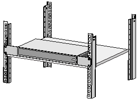
Mounting in a 19-inch rack
No mounting brackets and screws are provided with the switch. Prepare them yourself.
To install the switch in a 19-inch rack:
1. Verify that the rack is reliably grounded and is stable.
2. Use screws to attach the mounting brackets to both sides of the chassis.
Figure 1 Attaching mounting brackets to the switch

3. Place the switch on a rack shelf in the rack. Push the switch in until the oval holes in the brackets align with the mounting holes in the front rack posts.
4. Use screws to secure the mounting brackets to the front rack posts.
Figure 2 Mounting the switch in the rack
|
|
NOTE: Mounting brackets are used only for securing the switch to the rack. A rack shelf on the rack is required to bear the switch weight. |
Mounting on a workbench
1. Verify that the workbench is clean, sturdy, and reliably grounded.
2. Place the switch bottom up, and clean the four recessed areas in the chassis bottom with a soft and dry cloth.
3. Attach the rubber feet to the recessed areas.
4. Place the switch upside up on the workbench.
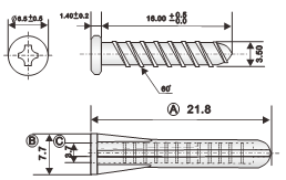
Mounting on a wall
You can use pan-head screws and the mounting holes in the switch bottom to mount the switch on a wall.
No screws and screw anchors are provided with the switch. Prepare them yourself. The following figure shows the screw and screw anchor of the recommended size.
Figure 3 Screw and screw anchor of the recommended size (mm)
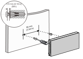
To mount the switch on a wall:
1. Determine the hole diameter and depth based on the screw and screw anchor size. Make sure the screw anchor can be inserted into the hole and seated flush with the wall and the screw can be fastened securely into the anchor.
If you use screws and screw anchors of the recommended size, the hole diameter is 5 mm (0.20 in).
2. Drill two holes spacing 90 mm (3.54 in) on the wall. Make sure the two holes are on a horizontal line.
3. Fasten a screw anchor into each hole and make sure the anchor is flush with the wall.
4. Insert a screw into each anchor, leaving a minimum of 2.5 mm (0.10 in) between the screw head and wall for mounting the switch
5. Align the two mounting holes in the switch bottom with the screws and hang the switch on the screws.
Figure 4 Mounting the switch on a wall
Connecting cables
Connecting the grounding cable
|
|
CAUTION: Correctly connecting the grounding cable is crucial to lightning protection and EMI protection. |
The switch is not provided with a grounding cable. Prepare one yourself.
The S9G switch does not have a grounding screw and you do not need to connect a grounding cable for it.
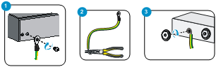
To connect the grounding cable:
1. Use a Phillips screwdriver to remove the grounding screw from grounding hole in the rear panel of the chassis. Use the grounding screw to attach the ring terminal of the grounding cable to the grounding hole. Fasten the grounding screw into the grounding hole.
2. Use needle-nose pliers to make a loop at the other end of the cable.
3. Remove the hex nut from a grounding post on the grounding strip. Attach the loop to the grounding post and fasten the hex nut.
Figure 5 Connecting the grounding cable
Connecting the power cord
Connecting the AC power cord
The S26 and S26G switches support AC power input.
To connect the AC power cord:
1. Make sure the switch is reliably grounded.
2. Connect one end of the AC power cord to the AC power receptacle on the switch.
3. Connect the other end of the AC power cord to an AC power source.
Connecting a power adapter
You can power the S9G switch by using a power adapter.
To connect the power adapter:
1. Connect the DC connector of the power adapter to the DC power receptacle on the switch.
2. Connect the plug of the power adapter to an AC power source.
Installing an SFP transceiver module and optical fibers
|
|
CAUTION: · When you install or remove an SFP transceiver module, do not touch the golden plating on it. · Remove the dust plugs from an SFP transceiver module only when you are to connect optical fibers to the module. · Before installing an SFP module, remove the optical fibers, if any, from it. |
To install an SFP transceiver module and optical fibers:
1. Wear an ESD wrist strap and make sure it makes good skin contact and is reliably grounded.
2. Pivot the bail latch of the module up. Holding the module by its two sides, gently push the module into the slot until it has firm contact with the slot.
Figure 6 Installing the SFP transceiver module
3. Remove the dust caps from the optical fibers, and the dust plug from the transceiver module.
4. Connect the LC connectors of the optical fibers to the transceiver module.
Figure 7 Installing the optical fibers

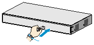
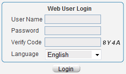
Accessing the switch
The switch supports Web management.
To access the switch:
1. Connect the switch to a PC. Make sure the switch and PC are reachable to reach other.
By default, the management IP address of the switch is 192.168.0.233 and the subnet mask is 255.255.255.0.
2. Enter http://192.168.0.233 in the address bar of your browser.
3. On the login page that opens, enter the user name, password, and verification code, select the language, and click Login.
The default username and password are admin (case-sensitive).
Figure 8 Accessing the switch
Appendix A Chassis views and technical specifications
Chassis views
Front panel
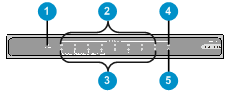
Figure 10 S26 front panel
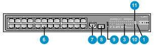
Figure 11 S26G front panel
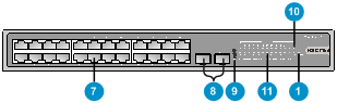
|
(1) Power LED (Power) |
|
|
(2) 1000Base-T copper port status LED |
|
|
(3) 10/100Base-TX copper port status LED |
|
|
(4) 1000Base-X SFP fiber port status LED |
|
|
(5) 100Base-X SFP fiber port status LED |
|
|
(6) 10/100Base-TX copper port |
|
|
(7) 10/100/1000Base-T copper port |
|
|
(8) 100/1000Base-X SFP fiber port |
(9) Reset button |
|
(10) 100/1000Base-X SFP fiber port status LED |
|
|
(11) 10/100/1000Base-T copper port status LED |
|
|
|
NOTE: You can use a paper clip to press the reset button. The reset button provides the following functions: · Restoring the Telnet and Web login passwords to admin—Press the reset button for about 5 seconds until the power LED slowly flashes green. · Restoring the factory default and rebooting the switch—Press the reset button for about 10 seconds until the power LED fast flashes green. If you press the reset button for over 15 seconds until the power LED turns steady green, the system does not perform any restoring tasks. |
Rear panel
Figure 12 S9G rear panel
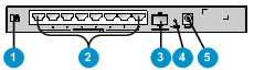
Figure 13 S26/S26G rear panel

|
(1) Security slot |
|
|
(2) 10/100/1000Base-T copper port |
|
|
(3) 100/1000Base-X SFP fiber port |
|
|
(4) Reset button |
(5) 12 VDC power receptacle |
|
(6) Grounding screw |
(7) AC power receptacle |
Technical specifications
Table 2 Technical specifications
|
Item |
S9G |
S26 |
S26G |
|
|
Dimensions (H × W × D) |
27 × 235 × 105 mm (1.06 × 9.25 × 4.13 in) |
44 × 330 × 173 mm (1.73 × 12.99 × 6.81 in) |
44 × 330 × 173 mm (1.73 × 12.99 × 6.81 in) |
|
|
Weight |
≤ 0.5 kg (1.10 lb) |
≤ 1.5 kg (3.31 lb) |
≤ 1.6 kg (3.53 lb) |
|
|
Port |
8 × 10/100/ 1 × 100/1000 |
24 × 10/100Base-TX copper port 1 × 10/100/1000Base-T copper port 1 × 100/1000Base-X SFP fiber port |
24 × 10/100/1000Base-T copper port 2 × 100/1000 |
|
|
Power consumption (static) |
5.5 W |
7.5 W |
12 W |
|
|
Power consumption (full configuration) |
≤ 9 W |
≤ 10.5 W |
≤ 18.6 W |
|
|
Cooling system |
Natural cooling |
|||
|
Input voltage |
DC: 12 V/1 A |
AC: 100 VAC to 240 VAC @ 50 Hz or 60 Hz |
||
|
Connector |
Fiber port: LC Copper port: RJ-45 |
|||
|
Port transmission rate |
Fiber port: 1000/100 Mbps, full duplex Copper port: Half/full duplex, auto-negotiation, MDI/MDI-X |
|||
|
Overall leakage current |
GB4943.1 |
|||
|
Operating temperature |
0°C to 40°C (32°F to 104°F) |
|||
|
Operating relative humidity |
5% RH to 95% RH, noncondensing |
|||
|
Fire resistance compliance |
GB4943.1 |
|||
Appendix B LEDs
|
LED |
Status |
Description |
|
Power LED (power) |
Steady green |
The switch is powered on and the power module is operating correctly. |
|
Flashing green |
The switch is powered on and is performing the self-test. |
|
|
Off |
The switch is not powered on or the power module is faulty. |
|
|
10/100/1000 |
Steady green |
A 1000-Mbps link is present. |
|
Flashing green |
The port is receiving or sending data at 1000 Mbps. |
|
|
Steady yellow |
A 10/100-Mbps link is present. |
|
|
Flashing yellow |
The port is receiving or sending data at 10/100 Mbps. |
|
|
Off |
No link is present. |
|
|
10/100 Base-TX copper port status LED on the S26 switch (Link/Act) |
Steady green |
A 10/100-Mbps link is present. |
|
Flashing green |
The port is receiving or sending data at 10/100 Mbps. |
|
|
Off |
No link is present. |
|
|
1000Base-T copper port status LED on the S9G switch (Link/Act) |
Steady green |
A 1000-Mbps link is present. |
|
Flashing green |
The port is receiving or sending data at 1000 Mbps. |
|
|
Off |
No link is present. |
|
|
10/100Base-TX copper port status LED on the S9G switch (Link/Act) |
Steady yellow |
A 10/100-Mbps link is present. |
|
Flashing yellow |
The port is receiving or sending data at 10/100 Mbps. |
|
|
Off |
No link is present. |
|
|
100/1000 |
Steady green |
A 1000-Mbps link is present. |
|
Flashing green |
The port is receiving or sending data at 1000 Mbps. |
|
|
Steady yellow |
A 100-Mbps link is present. |
|
|
Flashing yellow |
The port is receiving or sending data at 100 Mbps. |
|
|
Off |
No link is present. |
? 2017 New H3C Technologies Co., Ltd.
Website: http://www.h3c.com.hk
E-mail: [email protected]
