
- Released At: 13-09-2023
- Page Views:
- Downloads:
- Table of Contents
- Related Documents
-
AD-Campus 6.2
Multi-Campus Multi-Fabric Configuration Guide
Document version: 5W100-20230221
Copyright © 2023 New H3C Technologies Co., Ltd. All rights reserved.
No part of this manual may be reproduced or transmitted in any form or by any means without prior written consent of New H3C Technologies Co., Ltd.
Except for the trademarks of New H3C Technologies Co., Ltd., any trademarks that may be mentioned in this document are the property of their respective owners.
The information in this document is subject to change without notice.
Content
Configure the multi-fabric network
Configure multi-fabric interconnection with the management area of the headquarters campus
Configure the egress router of Fabric1
Configure VLAN-interface 1 and VLAN-interface 4094 for the egress router of Fabric2
Configure Layer 3 connectivity between Fabric1 and Fabric2
Configure the Layer 3 management switch for the headquarters in Fabric1
Configure multi-campus automation
Create multiple fabrics on the controller interface
Configure automated onboarding for Fabric1 and Fabric2
Configure multi-campus multi-fabric interconnection
Configure Layer 3 connectivity between EDs of multiple fabrics in multiple campuses
Configure fabric connection for the controller
Configure fabric connection for a single leaf
Deploy EIA, DHCP, and AC in multiple campuses
Configure authentication server settings for an isolation domain
Configure policy template settings
Configure the multi-campus BYOD service
Create BYOD Layer 2 network domains in the multi-campus scenario
Create BYOD security groups in the multi-campus scenario
Create access services in the multi-campus scenario
Configure fabric interconnection through a management switch
Configure the management switch
Configure multi-campus automation
Configure Layer 3 connectivity between EDs of multiple fabrics in multiple campuses
Overview
Introduction
· A fabric is a basic network of the standard three-tier (spine/leaf/access) or two-tier (leaf/access) architecture. A campus corresponds to the concept of isolation domains of AD campus controllers. It is a set of autonomous network domains that must contain fabric, DHCP, and EIA. A campus can contain one or multiple fabrics. Multiple fabrics of multiple campuses can be interconnected through WAN.
· The single-campus multi-fabric scenario requires interconnection of VXLANs. When users move across different fabrics, the associated network segment does not change, and a bypass issue might exist for the return traffic from the external network.
· The multi-campus multi-fabric scenario does not require interconnection of VXLANs. When users move across different fabrics, the associated network segment changes, and no bypass issue exists for traffic. As a best practice, use the multi-campus multi-fabric scenario.
· For the multi-campus multi-fabric scenario, as a best practice, deploy SeerEngine-Campus, vDHCP, fail-permit DHCP, and EIA V9 at the headquarters. In addition, deploy local service DHCP, hierarchical EIA, and fail-permit DHCP for each campus.
Typical networking models
Network topology
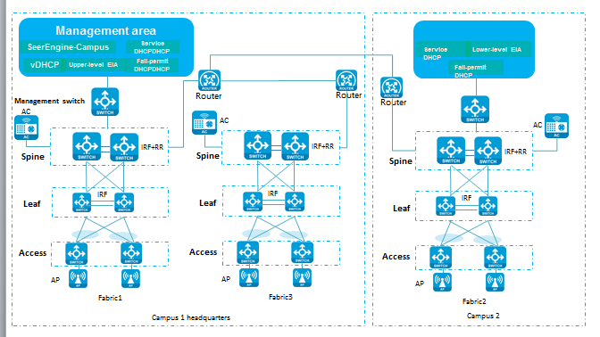
As shown in Figure 1, all control traffic and service traffic are forwarded through the spine (ED) devices (core switches with high performance) at the headquarters. The core spine (ED) in each fabric is directly connected to the egress router. VLAN 1 and VLAN 4094 of the spines are directly connected to the egress router. The gateways for VLAN 1 and VLAN 4094 are configured through Layer 2 interfaces or Layer 3 subinterfaces on the egress router. If the egress router does not support Layer 2 interfaces or Layer 3 subinterfaces, you need to connect a device that supports VLAN 1 and VLAN 4094 gateway configuration to the spine (ED) and egress router.
For single-fabric multi-border egress configuration, see AD-Campus 6.2 Basic Configuration Guide. Configure multi-border egress for each fabric.
Figure 1 Multi-campus networking model
Deployment workflow
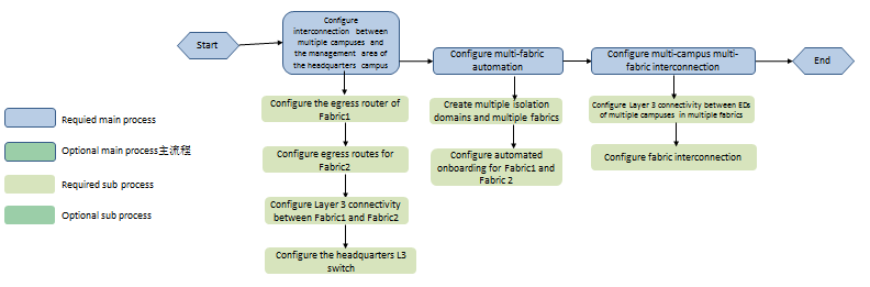
This document mainly describes multi-campus multi-fabric configuration in details. Configure single-campus multi-fabric in the same way (this document introduces only the differences between single-campus multi-fabric configuration and multi-campus multi-fabric configuration). Multi-campus multi-fabric configuration typically includes interconnecting multiple campuses and the management area of the headquarters campus, multi-campus automation, and multi-campus multi-fabric interconnection.
This section describes the configuration of two campuses and two fabrics. The spine in the network acts as the ED of the fabric.
· To interconnect multiple campuses and the management area of the headquarters campus, first connect the campus fabrics with the management area of the headquarters campus. As shown in the network, the egress router of Fabric 1 connects other fabrics. For device automation purposes of other fabrics, establish OSPF neighbors between the egress router and spine (ED) of Fabric 1. In addition, advertise the IP address of SeerEngine-Campus/DHCP in the management area of Fabric 1 to other fabrics. Then configure a static route on the management switch to Fabric 2, with headquarters campus spine (ED) as the next hop.
· To configure multi-campus automation, see AD-Campus 6.2 Automation Configuration Guide. Other fabrics in the network connect to the management area through the spine (ED) in Fabric 1. The spine (ED) in Fabric 1 performs automated onboarding first. The devices in the two fabrics perform automated onboarding in sequence.
· For multi-campus multi-fabric interconnection, advertise the loopback interface address on the spine (ED) to the spines (EDs) in other fabrics, so as to establish BGP EVPN neighbors between spines (EDs) in multiple fabrics. Configure multi-fabric connection settings on the controller interface. The BGP configuration of the spines (EDs) can be automatically issued for BGP EVPN neighbor establishment. In addition, manually enable DCI on the Layer 3 interfaces connecting the spines (EDs) and egress routers for VLAN-DCI tunnel setup between different fabrics.
Figure 2 Configuration workflow
Configure the multi-fabric network
This section describes interconnection between two fabrics as an example.
Resource planning
Figure 3 Multi-campus networking
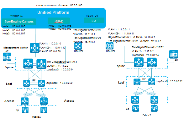
Table 1 IP address list
|
Item |
Example |
Description |
|
Underlay IP network address |
200.1.1.0/24 |
Network address of the loopback interfaces on spines and leafs |
|
Northbound service IP of Unified Platform |
100.1.0.100 |
IP address used to log in to Unified Platform |
|
EIA |
100.1.0.100 |
EIA server address |
|
EIA2 |
100.1.0.120 |
IP address of the other EIA server for multi-EIA configuration in "Deploy EIA, DHCP, and AC in multiple campuses." |
|
SeerEngine-Campus cluster IP |
110.1.0.100 |
IP address of the SeerEngine-Campus cluster |
|
SeerEngine-Campus node IP |
Node 1: 110.1.0.101 Node 2: 110.1.0.102 Node 3: 110.1.0.103 |
IP addresses of the three nodes in the SeerEngine-Campus cluster |
|
vDHCP cluster IP |
110.1.0.104 |
vDHCP server cluster address not actually used |
|
vDHCP node IP |
Node 1: 110.1.0.105 Node 2: 110.1.0.106 |
IP addresses of the two nodes used by the vDHCP server. |
|
Fabric1 in Campus 1 |
Fabric2 in Campus 2 |
||
|
Device |
Interfaces and IP addresses |
Device |
Interfaces and IP addresses |
|
Egress router |
· VLAN-interface 16: 16.16.0.1 (for Fabric1 and Fabric2 interconnection) · VLAN-interface 11: 11.11.0.1 (for ED and egress router interconnection) |
Egress router |
· VLAN-interface 1: 111.0.0.11 (manually configured) · VLAN-interface 4094: 111.0.9.11 (manually configured) · VLAN-interface 16: 16.16.0.2 (for Fabric1 and Fabric2 interconnection) · VLAN-interface 12: 12.12.0.1 (for ED and egress router interconnection) |
|
Management switch |
· VLAN 1 network (gateway): 120.1.0.0/24 (120.1.0.1) (manually configured) · VLAN 4094 network (gateway): 130.1.0.0/24 (130.1.0.1) (manually configured) · VLAN 30 network (gateway): 100.1.0.0/24 (100.1.0.1) (Unified Platform) · VLAN 1010 network (gateway): 100.1.0.0/24 (100.1.0.1) (network used by SeerEngine-Campus&vDHCP) |
N/A |
N/A |
|
Spine (ED) |
· VLAN-interface 11: 11.11.0.2 (manually configured) · LoopBack0: 200.1.1.254 (automatically deployed or manually configured) · VLAN 4094 address: 120.1.0.2 (automatically obtained or manually configured) |
Spine (ED) |
· VLAN-interface 12: 12.12.0.2 (manually configured) · LoopBack0: 20.0.0.254 (automatically deployed or manually configured) |
|
Leaf |
LoopBack0: 200.1.1.252 (automatically deployed or manually configured) |
Leaf |
LoopBack0: 20.0.0.252 (automatically deployed or manually configured) |
Description of the VLANs and IP addresses in the table:
· Configure a routing protocol for VLAN-interface 16 of the egress router in Fabric1 of campus 1 and VLAN-interface 16 of the egress router in Fabric2 of campus 2. This example uses OSPF as an example. Configure VLAN 16 as needed.
· Establish OSPF neighbor relationship between VLAN-interface 11 of the egress router and VLAN-interface 11 of the spine (ED) in Fabric1 of campus 1. Configure VLAN 16 as needed. Make sure no duplicate VLANs exist.
· Use VLAN-interface 1 and VLAN-interface 4094 of the management switch in Fabric1 of campus 1 for automated device onboarding of campus 1.
· Use VLAN-interface 1 and VLAN-interface 4094 of the management switch in Fabric2 of campus 2 for automated device onboarding of campus 2.
· Establish OSPF neighbor relationship between VLAN-interface 12 of the egress router and VLAN-interface 12 of the spine (ED) in Fabric2 of campus 2. Configure VLAN 12 as needed. Make sure no duplicate VLANs exist.
Configure multi-fabric interconnection with the management area of the headquarters campus
Configure the egress router of Fabric1
# Configure VLAN-interface 11 for establishing OSPF neighbor relationship with the spine (ED).
#
vlan 11
#
#
interface Ten-GigabitEthernet5/0/3
port link-mode bridge
port link-type trunk
undo port trunk permit vlan 1
port trunk permit vlan 11 //Configure the ED-connected port as a trunk port that allows VLAN 11 to pass through.
#
interface Vlan-interface11
ip address 11.11.0.1 255.255.255.0 //Network IP address of VLAN 11.
ospf 1 area 0.0.0.0
#
Configure VLAN-interface 1 and VLAN-interface 4094 for the egress router of Fabric2
The egress router of Fabric2 acts as the DHCP relay agent of the local fabric.
# Enable DHCP globally.
dhcp enable
# Configure VLAN-interface 1 and DHCP relay agent.
interface Vlan-interface1
ip address 111.0.0.11 255.255.255.0 //Network address of VLAN1 in Fabric2.
dhcp select relay
dhcp relay server-address 110.1.0.105
dhcp relay server-address 110.1.0.106
# Configure VLAN-interface 4094.
interface Vlan-interface4094
ip address 111.0.9.11 255.255.255.0 //Network address of VLAN 4094 in Fabric2.
Configure Layer 3 connectivity between Fabric1 and Fabric2
Configure OSPF between the egress router of Fabric1 and the egress router of Fabric2. The two fabrics are connected through WAN or other networks. Make sure the devices in Fabric2 can communicate with the controller of the headquarters.
Configure the egress router of Fabric1
#
interface Ten-GigabitEthernet5/0/5 //Interface of the egress router in Fabric1 connected to Fabric2.
port link-mode bridge
port access vlan 16
#
interface Vlan-interface16
ip address 16.16.0.1 255.255.255.0
ospf 1 area 0.0.0.0
#
Configure the egress router of Fabric2
#
interface GigabitEthernet1/0/1 //Interface of the egress router in Fabric2 connected to Fabric1.
port access vlan 16
#
interface Vlan-interface16
ip address 16.16.0.2 255.255.255.0
ospf 1 area 0.0.0.0
#
ospf 1
import-route direct
area 0.0.0.0
#
Configure the Layer 3 management switch for the headquarters in Fabric1
#
dhcp enable //Enable DHCP globally.
#
interface Vlan-interface1
ip address 120.1.0.1 255.255.255.0
dhcp select relay //Configure the DHCP reply agent.
dhcp relay server-address 110.1.0.105
dhcp relay server-address 110.1.0.106
#
interface Vlan-interface4094
ip address 130.1.0.1 255.255.255.0
#
ip route-static 111.0.0.0 24 120.1.0.2 //Configure a static route to VLAN 1 in Fabric2, with the IP address of spine VLAN 1 as the next hop.
ip route-static 111.0.9.0 24 120.1.0.2 //Configure a static route to VLAN 4094 in Fabric2, with the IP address of spine VLAN 1 as the next hop.
#
Configure multi-campus automation
Create multiple fabrics on the controller interface
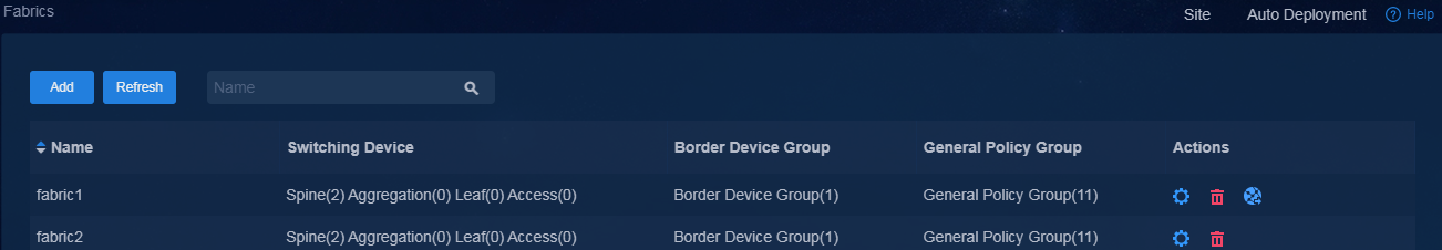
Navigate to the Automation > Campus Network > Fabrics page, and create fabric1 with AS number 100 and fabric2 with AS number 200. For more information about fabric configuration, see device onboarding plan in AD-Campus 6.2 Basic Configuration Guide.
Figure 4 Creating fabrics
Configure automated onboarding for Fabric1 and Fabric2
Complete automation configuration and then perform configuration as described in "Configure Layer 3 connectivity between EDs of multiple fabrics in multiple campuses." Then restore the factory default settings for the devices in Fabric2 of campus 2 and reboot the devices to implement automated onboarding. For more information about automation configuration, see AD-Campus 6.2 Automation Configuration Guide.
|
|
CAUTION: After completing ED onboarding in Fabric1, configure ED settings, so that the devices in Fabric2 can correctly implement automated onboarding. Configure OSPF settings on the ED. Without OSPF settings, the egress router in Fabric2 lacks routes to vDHCP. As a result, device automation in Fabric2 fails. |
Configure multi-campus multi-fabric interconnection
Configure Layer 3 connectivity between EDs of multiple fabrics in multiple campuses
Configure the ED in Fabric1
# Configure OSPF and DCI settings.
#
ospf 1
area 0.0.0.0
import-route static //Used for advertising routes to the controller on the egress router in Fabric1.
network 200.1.1.254 0.0.0.0 //Advertise the IP address of LoopBack0.
#
vlan 11
#
interface Vlan-interface11
ip address 11.11.0.2 255.255.255.0
ospf 1 area 0.0.0.0
dci enable
#
#
interface Ten-GigabitEthernet1/1/0/3 //Interface of the ED connected to the egress router.
port link-mode bridge
port link-type trunk
port trunk permit vlan 11
#
Configure the egress router of Fabric1
#
vlan 11
#
interface Ten-GigabitEthernet5/0/3 //Interface of the egress router connected to the ED.
port link-mode bridge
port link-type trunk
port trunk permit vlan 11
#
interface Vlan-interface11
ip address 11.11.0.1 255.255.255.0
ospf 1 area 0.0.0.0
#
Configure the ED in Fabric2
# Configure OSPF and DCI settings.
#
vlan 12
#
#
interface Vlan-interface12
ip address 12.12.0.2 255.255.255.0
ospf 1 area 0.0.0.0
dci enable
#
ospf 1
area 0.0.0.0
network 20.0.0.254 0.0.0.0
#
#
interface Ten-GigabitEthernet1/2/0/32 //Interface of the ED connected to the egress router. The configuration is automatically deployed during device automation.
port link-mode bridge
port link-type trunk
port trunk permit vlan all
#
service-instance 4094
encapsulation s-vid 4094
xconnect vsi vxlan4094
#
Configure the egress router of Fabric2
#
interface Ten-GigabitEthernet1/0/52 //Interface of the egress router connected to the ED.
port link-type trunk
port trunk permit vlan 1 12 4094
#
interface Vlan-interface12
ip address 12.12.0.1 255.255.255.0
ospf 1 area 0.0.0.0
#
Configure fabric connection for the controller
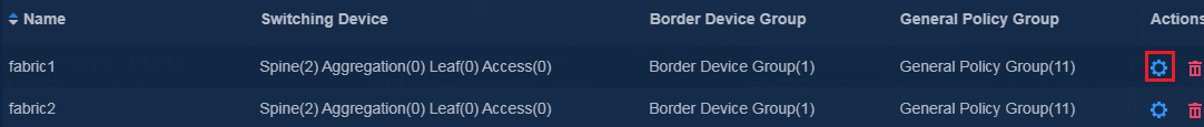
1. Edit the switching devices (EDs of Fabric1 and Fabric2) by using one of the following methods:
¡ Navigate to the Automation > Campus Network > Fabrics page, and then click the Settings icon in the Actions column for a fabric in the fabric list to enter the device resource page. Click the Switch Devices tab, and then click the Edit icon in the Actions column for a device in the device list to enter the switching device modification page.
Figure 5 Device resources

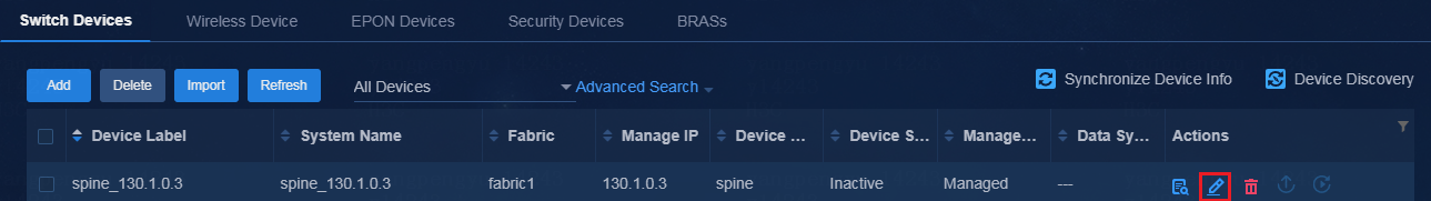
¡ Navigate to the Automation > Network Devices > Switch Devices page, and then click the Edit icon in the Actions column for the spine device in the device list to enter the switching device modification page.
Figure 6 Physical devices
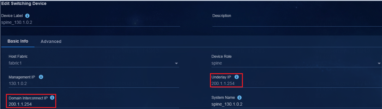
2. On the switching device modification page, specify the domain interconnect IP (as a best practice, specify the underlay IP for this parameter) as follows. After modification, click OK.
|
|
IMPORTANT: The domain interconnect IP is not required for single isolation domain in multiple fabrics, and is required for multiple isolation domains in multiple fabrics. |
Figure 7 Editing the switching devices (EDs in Fabric1 and Fabric2)
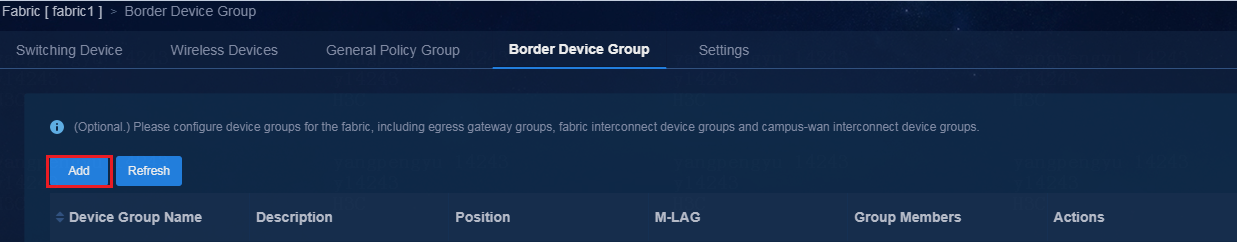
3. Click the Border Device Group tab, and click Add to enter the page for adding a border device group.
Figure 8 Border device groups
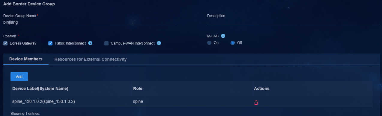
4. Select Fabric Interconnect for Position, and then click Add to add the ED as a member to the border device group.
Figure 9 Adding a border device group
|
|
NOTE: Select the Fabric Interconnect option for both the multi-campus multi-fabric and single-campus multi-fabric scenarios. |
5. Follow steps 1 to 4 to edit the spine device in Fabric2. Specify the domain interconnect IP, select the Fabric Interconnect option, and add a member to the border device group for Fabric2.
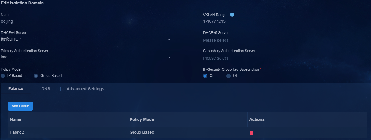
6. Navigate to the Automation > Campus Network > Isolation Domain page, and add Fabric1 and Fabric2 to their respective isolation domains. Click the Edit icon in the Actions column to enter the isolation domain modification page. In the fabric list, click Add Fabric. On the page that opens, add fabrics to their respective isolation domains.
Figure 10 Editing the isolation domain
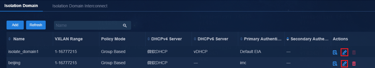
Figure 11 Adding Fabric1 to the associated isolation domain
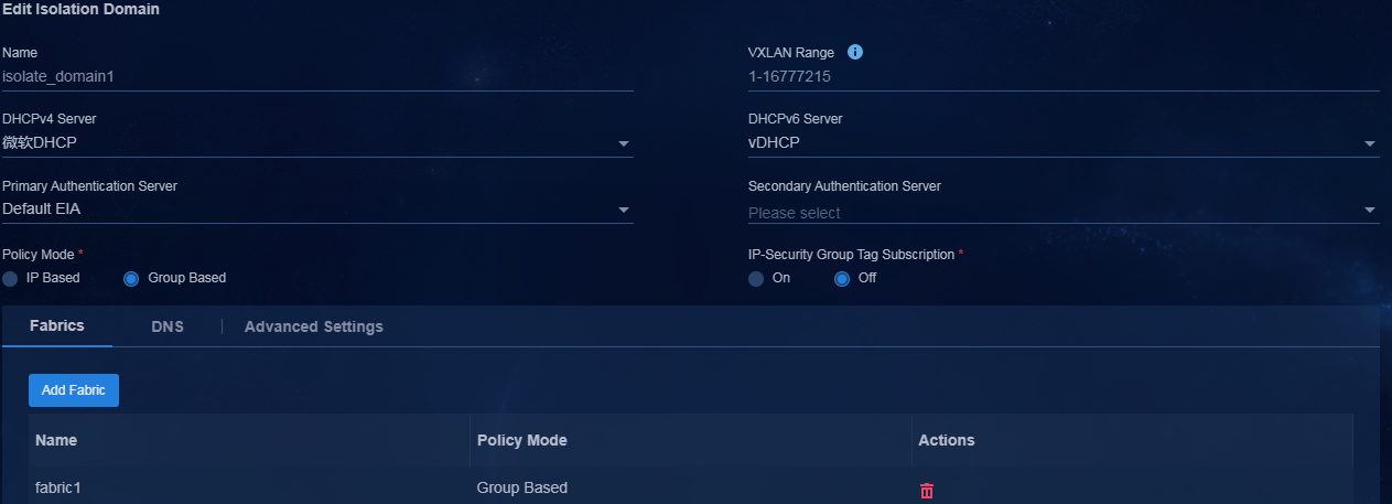
Figure 12 Adding Fabric2 to the associated isolation domain
Configure the full mesh connection mode
· In the multi-campus multi-fabric scenario:
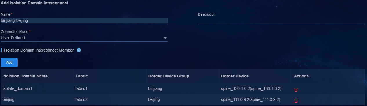
a. Navigate to the Automation > Campus Network > Isolation Domain > Isolation Domain Interconnect page to add an isolation domain interconnect.
b. Specify an isolation domain interconnect name, select User-Defined for Connection Mode, and then specify the fully interconnected mode for all members.
c. Click Add to add an isolation domain interconnect member, and specify the associated isolation domain and border device.
Figure 13 Adding an isolation domain interconnect member in the multi-campus multi-fabric scenario
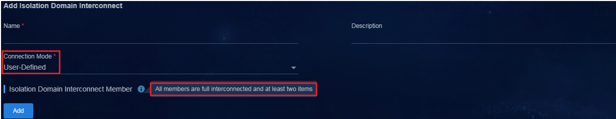
Figure 14 Adding an isolation domain interconnect member
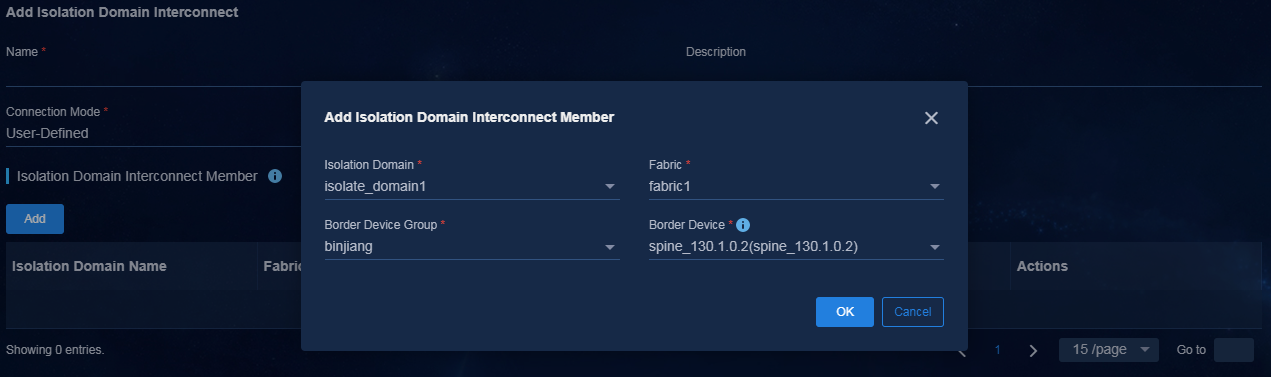
Figure 15 Added isolation domain interconnect in the multi-campus multi-fabric scenario
· In the single-campus multi-fabric scenario:
a. Navigate to the Automation > Campus Network > Isolation Domain > Isolation Domain page to add a fabric connection.
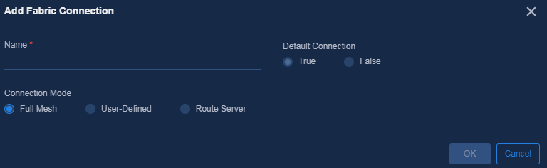
b. Specify a fabric connection name, select Full Mesh for Connection Mode, and use default settings for other parameters.
Figure 16 Adding a fabric connection in the single-campus multi-fabric scenario
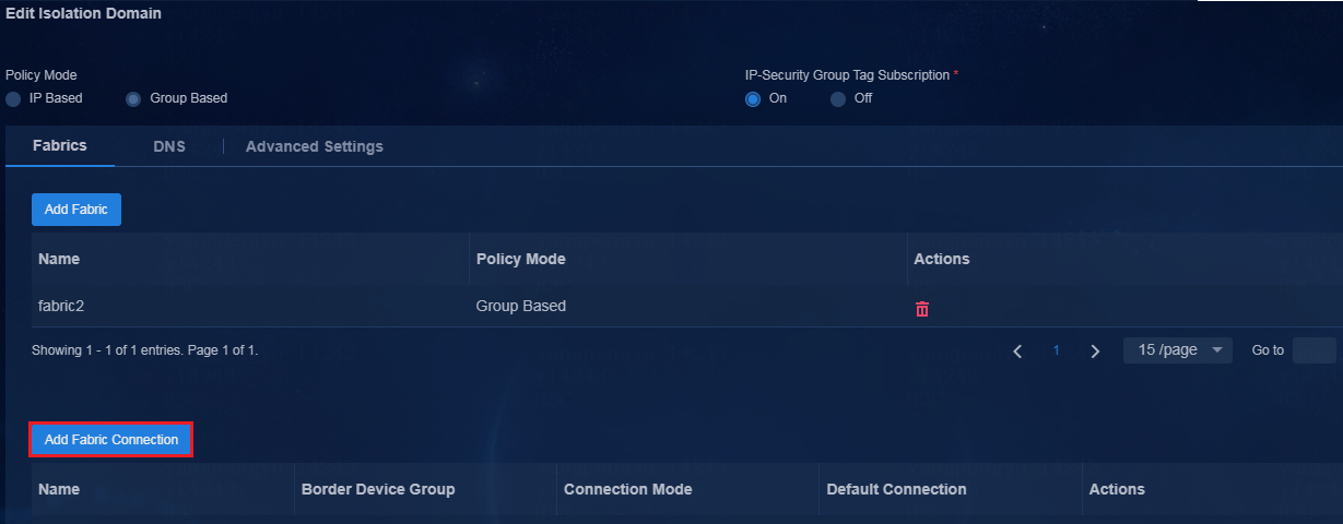
Figure 17 Setting fabric connection parameters in the single-campus multi-fabric scenario
After adding an isolation domain interconnect or fabric connection, deploy BGP configuration to the associated devices for configuring BGP EVPN neighbors and VXLAN tunnels between EDs in multiple fabrics.
|
|
IMPORTANT: To set up fabric connections if manually or automatically onboarded spine/RR devices act as EDs, you need to manually configure the next-hop-local command. |
ED configuration in Fabric1:
bgp 100
non-stop-routing
router-id 200.1.1.254
group SDN_NI_CONNECTION external //Multi-campus interconnect
peer SDN_NI_CONNECTION connect-interface LoopBack0 //Multi-campus interconnect
peer SDN_NI_CONNECTION ebgp-max-hop 64 //Multi-campus interconnect
peer 200.1.1.251 as-number 100
peer 200.1.1.251 connect-interface LoopBack0
peer 200.1.1.252 as-number 100
peer 200.1.1.252 connect-interface LoopBack0
peer 11.0.0.254 as-number 300 //Single-campus multi-fabric interconnect
peer 11.0.0.254 description SDN_FABRIC //Single-campus multi-fabric interconnect
peer 11.0.0.254 connect-interface LoopBack0 //Single-campus multi-fabric interconnect
peer 11.0.0.254 ebgp-max-hop 64 //Single-campus multi-fabric interconnect
peer 20.0.0.254 as-number 200 //Multi-campus interconnect
peer 20.0.0.254 group SDN_NI_CONNECTION //Multi-campus interconnect
#
address-family l2vpn evpn
peer SDN_NI_CONNECTION enable //Multi-campus interconnect
peer SDN_NI_CONNECTION router-mac-local //Multi-campus interconnect. The router MAC is edited upon receiving routes from Fabric2 and route advertisement.
peer 200.1.1.251 enable
peer 200.1.1.251 next-hop-local //Change the next hop of the route advertised to the BGP peers in the same fabric to the local address.
peer 200.1.1.251 reflect-client
peer 200.1.1.252 enable
peer 200.1.1.252 next-hop-local //Change the next hop of the route advertised to the BGP peers in the same fabric to the local address.
peer 200.1.1.252 reflect-client
peer 11.0.0.254 enable
peer 11.0.0.254 router-mac-local //Single campus multi-fabric interconnect. The router MAC is edited upon receiving routes from Fabric2 and route advertisement.
#
ED configuration in Fabric2 in the multi-campus scenario:
bgp 200
non-stop-routing
router-id 20.0.0.254
group SDN_NI_CONNECTION external
peer SDN_NI_CONNECTION connect-interface LoopBack0
peer SDN_NI_CONNECTION ebgp-max-hop 64
peer 200.1.1.254 as-number 100
peer 200.1.1.254 group SDN_NI_CONNECTION
peer 20.0.0.252 as-number 200
peer 20.0.0.252 connect-interface LoopBack0
#
address-family l2vpn evpn
peer SDN_NI_CONNECTION enable
peer SDN_NI_CONNECTION router-mac-local //The router MAC is edited upon receiving routes from Fabric1 and route advertisement.
peer 20.0.0.252 enable
peer 20.0.0.252 next-hop-local //Change the next hop of the route advertised to the BGP peers in the same fabric to the local address.
peer 20.0.0.252 reflect-client
Configure the route server connection mode
To implement route server connections, specify an ED in a specific fabric as the route server, and specify EDs in other fabrics as clients of the router server. User routes are available among multiple fabrics through only the establishment of EBGP peers between the clients and the route server.
· In the multi-campus multi-fabric scenario:
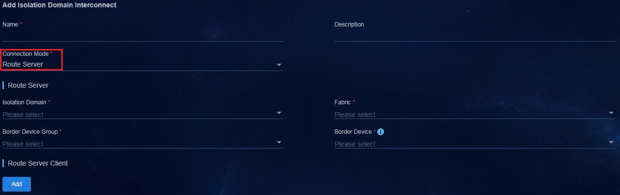
a. Navigate to the Automation > Campus Network > Isolation Domain > Isolation Domain Interconnect page to add an isolation domain interconnect.
b. Specify an isolation domain interconnect name and select Route Server for Connection Mode.
Figure 18 Selecting a connection mode
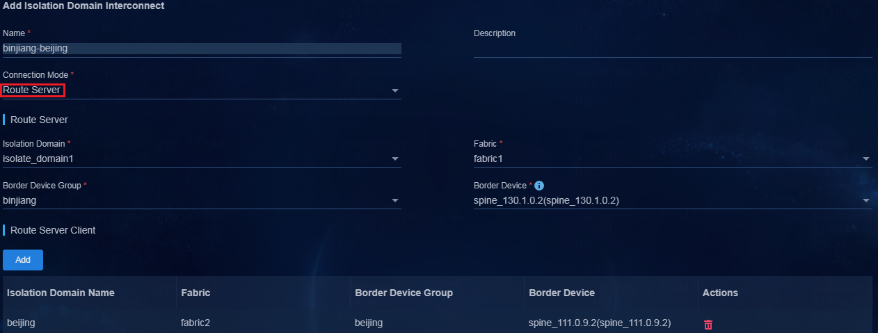
c. Specify the ED of an isolation domain as the route server, and specify the EDs of other isolation domains as clients of the route server. (Specify the route server and clients as planned.) You can specify only one route server and multiple clients for the route server.
Figure 19 Adding an isolation domain interconnect
· In the single-campus multi-fabric scenario:
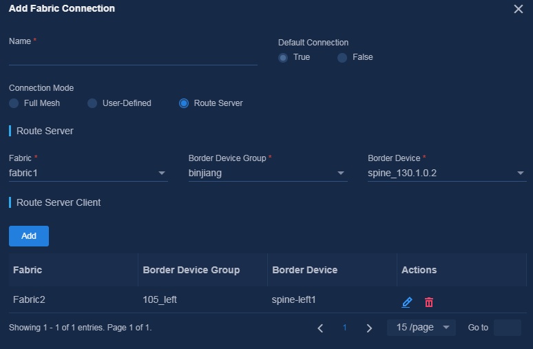
a. Navigate to the Automation > Campus Network > Isolation Domain > Isolation Domain page to add a fabric connection.
b. Specify a fabric connection name, and select Route Server for Connection Mode.
c. Select the ED of one fabric as the route server and the EDs of other fabrics as clients for the route server. (Specify the route server and clients as planned.) You can specify only one route server and multiple clients for the route server.
Figure 20 Adding a fabric connection

Figure 21 Configuring fabric connection parameters
After adding an isolation domain interconnect or fabric connection, deploy BGP configuration to the associated devices for configuring BGP EVPN neighbors and VXLAN tunnels between EDs in multiple fabrics.
|
|
IMPORTANT: To set up fabric connections if manually or automatically onboarded spine/RR devices act as EDs, you need to manually configure the next-hop-local command. |
ED configuration in Fabric1:
bgp 100
non-stop-routing
router-id 200.1.1.254
group SDN_NI_CONNECTION external //Multi-campus interconnect
peer SDN_NI_CONNECTION connect-interface LoopBack0 //Multi-campus interconnect
peer SDN_NI_CONNECTION ebgp-max-hop 64 //Multi-campus interconnect
peer 200.1.1.251 as-number 100
peer 200.1.1.251 connect-interface LoopBack0
peer 200.1.1.252 as-number 100
peer 200.1.1.252 connect-interface LoopBack0
peer 11.0.0.254 as-number 300 //Single-campus multi-fabric interconnect
peer 11.0.0.254 description SDN_FABRIC //Single-campus multi-fabric interconnect
peer 11.0.0.254 connect-interface LoopBack0 //Single-campus multi-fabric interconnect
peer 11.0.0.254 ebgp-max-hop 64 //Single-campus multi-fabric interconnect
peer 11.0.0.254 route-server-client external //Newly added command in the route server mode in the single-campus multi-fabric scenario
peer 20.0.0.254 as-number 200 //Multi-campus interconnect
peer 20.0.0.254 group SDN_NI_CONNECTION //Multi-campus interconnect
#
address-family l2vpn evpn
peer SDN_NI_CONNECTION enable //Multi-campus interconnect
peer SDN_NI_CONNECTION router-mac-local //Multi-campus interconnect. The router MAC is edited upon receiving routes from Fabric2 and route advertisement.
peer SDN_NI_CONNECTION route-server-client external //Newly added command in the route server mode in the multi-campus scenario
peer 200.1.1.251 enable
peer 200.1.1.251 next-hop-local //Change the next hop of the route advertised to the BGP peers in the same fabric to the local address.
peer 200.1.1.251 reflect-client
peer 200.1.1.252 enable
peer 200.1.1.252 next-hop-local //Change the next hop of the route advertised to the BGP peers in the same fabric to the local address.
peer 200.1.1.252 reflect-client
peer 11.0.0.254 enable
peer 11.0.0.254 router-mac-local //Single campus multi-fabric interconnect. The router MAC is edited upon receiving routes from Fabric2 and route advertisement.
#
ED configuration in Fabric2 in the multi-campus scenario:
bgp 200
non-stop-routing
router-id 20.0.0.254
group SDN_NI_CONNECTION external
peer SDN_NI_CONNECTION connect-interface LoopBack0
peer SDN_NI_CONNECTION ebgp-max-hop 64
peer SDN_NI_CONNECTION ignore-first-as //Newly added command in the route server mode
peer 200.1.1.254 as-number 100
peer 200.1.1.254 group SDN_NI_CONNECTION
peer 20.0.0.252 as-number 200
peer 20.0.0.252 connect-interface LoopBack0
#
address-family l2vpn evpn
peer SDN_NI_CONNECTION enable
peer SDN_NI_CONNECTION router-mac-local //The router MAC is edited upon receiving routes from Fabric1 and route advertisement.
peer 20.0.0.252 enable
peer 20.0.0.252 next-hop-local //Change the next hop of the route advertised to the BGP peers in the same fabric to the local address.
peer 20.0.0.252 reflect-client
Configure fabric connection for a single leaf
The fabric connection configuration for a single leaf is similar to the configuration described in "Configure fabric connection for the controller." This section introduces only the special settings.
1. Edit the switching devices (EDs of fabrics) by using one of the following methods:
¡ Navigate to the Automation > Campus Network > Fabrics page, and then click the Settings icon in the Actions column for a fabric in the fabric list to enter the device resource page. Click the Switch Devices tab, and then click the Edit icon in the Actions column for a device in the device list to enter the switching device modification page.
Figure 22 Device resources
¡ Navigate to the Automation > Network Devices > Switch Devices page, and then click the Edit icon in the Actions column for a leaf device in the list to enter the switching device modification page.
2. Enter the underlay IP (to assign a loopback address to the single leaf for setting up EBGP peers) and domain interconnect IP (as a best practice, specify the underlay IP for this parameter).
|
|
IMPORTANT: The domain interconnect IP is not required for single isolation domain in multiple fabrics, and is required for multiple isolation domains in multiple fabrics. |
Figure 23 Editing a switching device (ED of a fabric)

For information about other settings, see "Configure fabric connection for the controller."
Verify the configuration
Verify BGP EVPN neighbor information
<fabric1-ED>dis bgp peer l2vpn evpn
BGP local router ID: 200.1.1.254
Local AS number: 100
Total number of peers: 3 Peers in established state: 3
* - Dynamically created peer
Peer AS MsgRcvd MsgSent OutQ PrefRcv Up/Down State
200.1.1.251 100 251 281 0 13 02:59:04 Established
200.1.1.252 100 257 238 0 12 02:59:58 Established
20.0.0.254 200 241 242 0 15 02:59:00 Established
Verify information about VXLAN-DCI tunnels between fabrics
<fabric1-ED>dis int Tunnel 3
Tunnel3
Current state: UP
Line protocol state: UP
Description: Tunnel3 Interface
Bandwidth: 64 kbps
Maximum transmission unit: 64000
Internet protocol processing: Disabled
Last clearing of counters: Never
Tunnel source 200.1.1.254, destination 20.0.0.254
Tunnel protocol/transport UDP_VXLAN_DCI/IP
Last 300 seconds input rate: 0 bytes/sec, 0 bits/sec, 0 packets/sec
Last 300 seconds output rate: 0 bytes/sec, 0 bits/sec, 0 packets/sec
Input: 0 packets, 0 bytes, 0 drops
Output: 3 packets, 325 bytes, 0 drops
<fabric1-ED>
Deploy EIA, DHCP, and AC in multiple campuses
· For the multi-campus multi-fabric scenario, as a best practice, deploy SeerEngine-Campus, vDHCP, and EIA V9 at the headquarters. In addition, deploy local service DHCP, hierarchical EIA, and fail-permit DHCP for each campus.
· Each campus requires deploying a separate service DHCP server. For more information about the configuration, see AD-Campus 6.2 Tight Microsoft DHCP Management Configuration Guide.
· The links between campuses might be disconnected. As a best practice, deploy a fail-permit solution for each campus. For more information about the configuration, see AD-Campus 6.2 Basic Configuration Guide.
· As a best practice, deploy vDHCP for the headquarters to provide BYOD and automation services.
· Multiple campuses can reuse the EIA, service DHCP, and BYOD DHCP settings. As a best practice, do not reuse the service DHCP settings.
· As a best practice, deploy a set of ACs for each isolation domain in the multi-campus multi-fabric scenario. Create a wireless Layer 2 network domain for each isolation domain. Enter the AC addresses of the associated isolation domains. The configuration is consistent with AC controller deployment in the single-fabric scenario. For more information, see AD-Campus 6.2 Wireless Service Configuration Guide. The single-campus multi-fabric scenario supports using the same set of AC controllers. If each fabric uses a separate AC, you can configure only one wireless Layer 2 network domain, add multiple AC controllers, and configure a separate AP template for each AC controller. Auto registration must be disabled for the AC controllers. For more information about the configuration, see AD-Campus 6.2 Wireless Service Configuration Guide.
|
|
IMPORTANT: After DHCP deployment in the single-campus multi-fabric scenario, you need to manually add the network application scope of VSI-interface 4094 for different fabrics. For more information, see AD-Campus 6.2 Tight Microsoft DHCP Management Configuration Guide. |
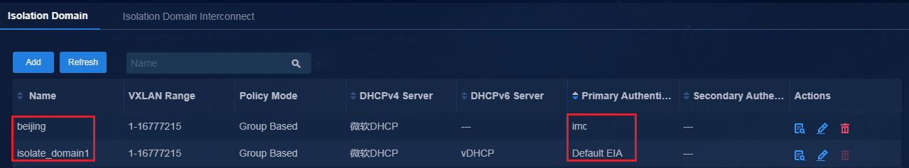
In the current software version, only the multi-campus multi-fabric scenario supports multi-EIA configuration. The single-campus multi-fabric scenario supports using only the same EIA server for authentication. In the multi-campus multi-fabric scenario, you can configure authentication servers in isolation domains to implement authentication with different EIA servers in various campuses. As shown in Figure 24, three campuses perform user authentication by using different authentication servers.
Figure 24 Viewing authentication servers
Configure AAA server settings
1. Navigate to the Automation > Campus Network > Network Parameters > AAA page.
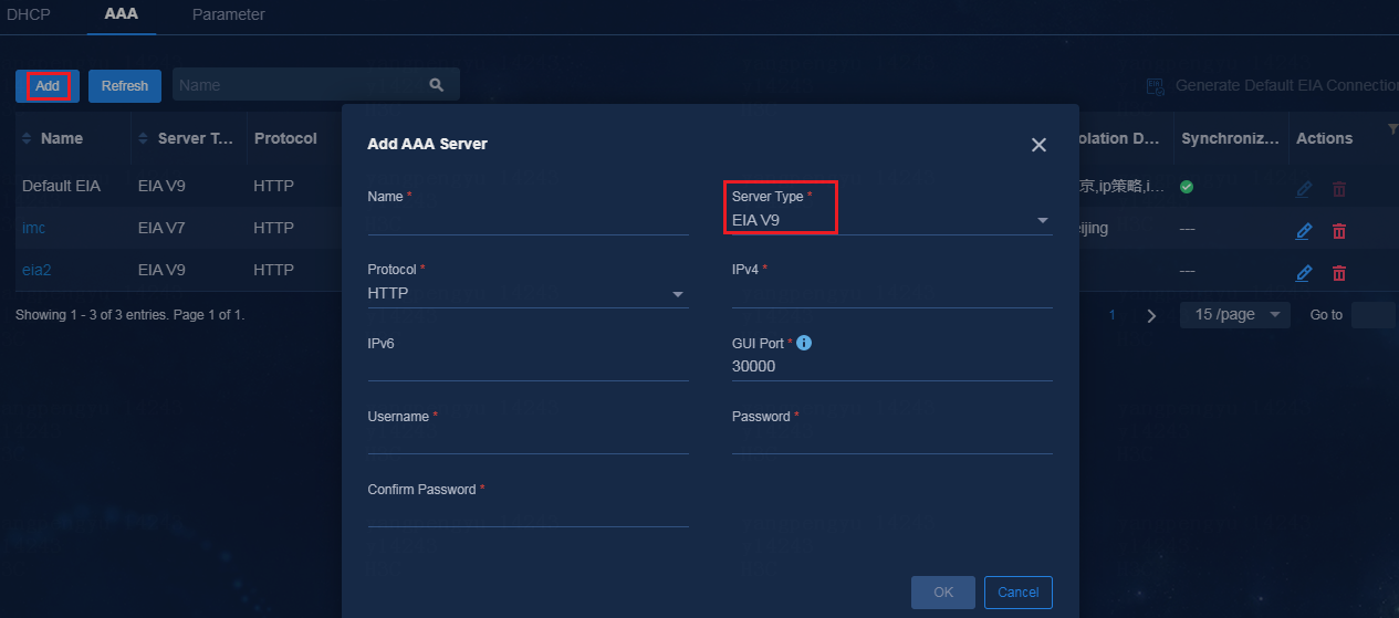
2. Click Add to add multiple EIA servers to implement authentication.
3. Configure the EIA server parameters as follows:
¡ Name: Enter a name that is not used by any AAA servers in the current environment.
¡ Server Type: Options include:
- EIA V9: EIA server deployed based on Unified Platform. The EIA server does not support hierarchical deployment.
- EIA V7: EIA server deployed based on the iMC platform. The EIA server supports hierarchical deployment.
- Third-Party Authentication: Used for Web portal authentication services.
¡ Protocol: Specify the protocol used for log in to the EIA server. The default protocol is HTTP. You can select HTTPS as needed.
¡ IPv4: Specify the IPv4 address of the EIA server.
¡ IPv6: Specify the IPv6 address of the EIA server.
¡ GUI Port: Automatically populated according to the selected server type.
¡ Username: Specify the username for accessing the EIA server.
¡ Password: Specify the password for accessing the EIA server.
Figure 25 Adding an authentication server
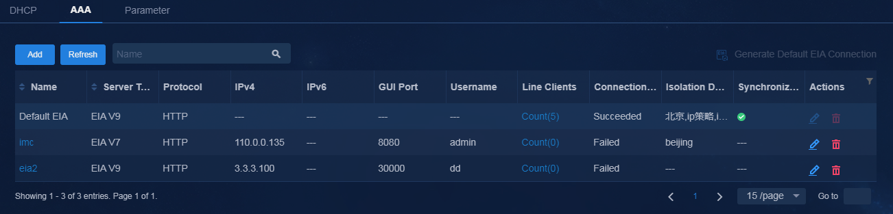
4. Click OK. You can see the added EIA server in succeeded state on the AAA list.
Figure 26 Added EIA server
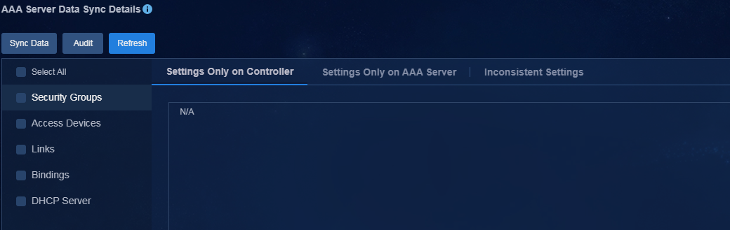
5. Click the synchronization state icon to enter the AAA server data sync details page. Check for data differences between the controller and EIA server. If data differences exist, perform data synchronization.
Figure 27 AAA server data sync details
|
|
IMPORTANT: You can perform audit and sync operations for security group and access device data in the campus deployed with the AAA server. For example, fabric data bound to isolation domain isolate_domain1 can be audited and synced under the default EIA server. Fabric data bound to isolation domain Beijing can be audited and synced only under EIA2 server. |
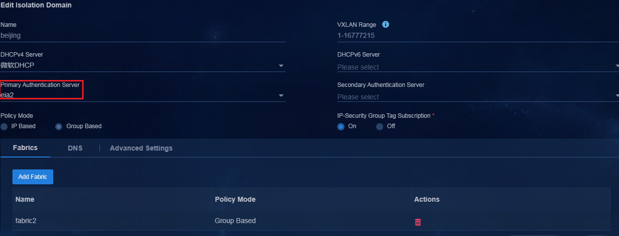
Configure authentication server settings for an isolation domain
1. Navigate to the Automation > Campus Network > Isolation Domain > Isolation Domain page to add or edit an isolation domain.
2. Specify an authentication server for the isolation domain, and click OK.
The private network, Layer 2 network domain, security group, access device, link relation, binding relation, and DHCP server information in Fabric1 bound to this isolation domain will be synced to EIA2 server.
Figure 28 Configuring an authentication server for the isolation domain
Configure policy template settings
After completing authentication server configuration for the isolation domain, make sure the authentication server specified in the authentication template is consistent with that in the isolation domain. This section takes isolation domain Beijing bound to Fabric1 as an example.
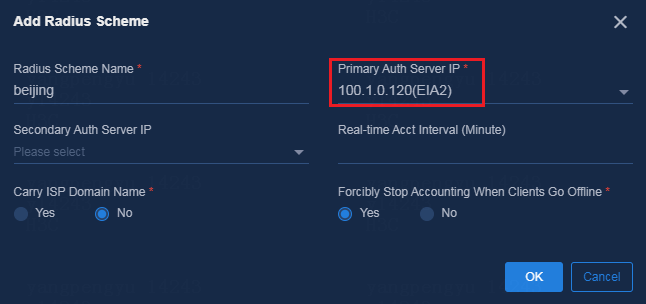
Configure AAA template settings
1. Navigate to the Automation > Campus Network > Network Devices > General Policy Groups page to add an AAA template.
2. In the RADIUS scheme parameter settings, configure the primary authentication server as EIA2 (consistent with isolation domain Beijing).
Figure 29 Adding a RADIUS scheme to the AAA template
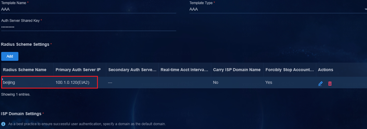
3. Configure other parameters, and then click OK.
Figure 30 Configuring other AAA template parameters
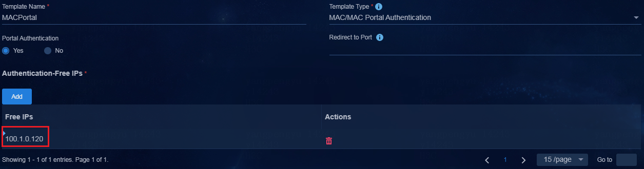
Configure MAC Portal template settings
1. Navigate to the Automation > Campus Network > Network Devices > General Policy Groups > Policy Template page to add a MAC/MAC Portal authentication template.
2. In the Authentication-Free IPs area, add the IP address of EIA2 server.
Figure 31 Authentication-free IPs
Apply the policy to a device group
1. Navigate to the Automation > Campus Network > Network Devices > General Policy Groups page.
2. Click Edit in the Actions column for the leaf device group associated with Fabric1.
3. On the Policy tab, click Add and select the device authentication template to be deployed.
Figure 32 Editing the general policy group
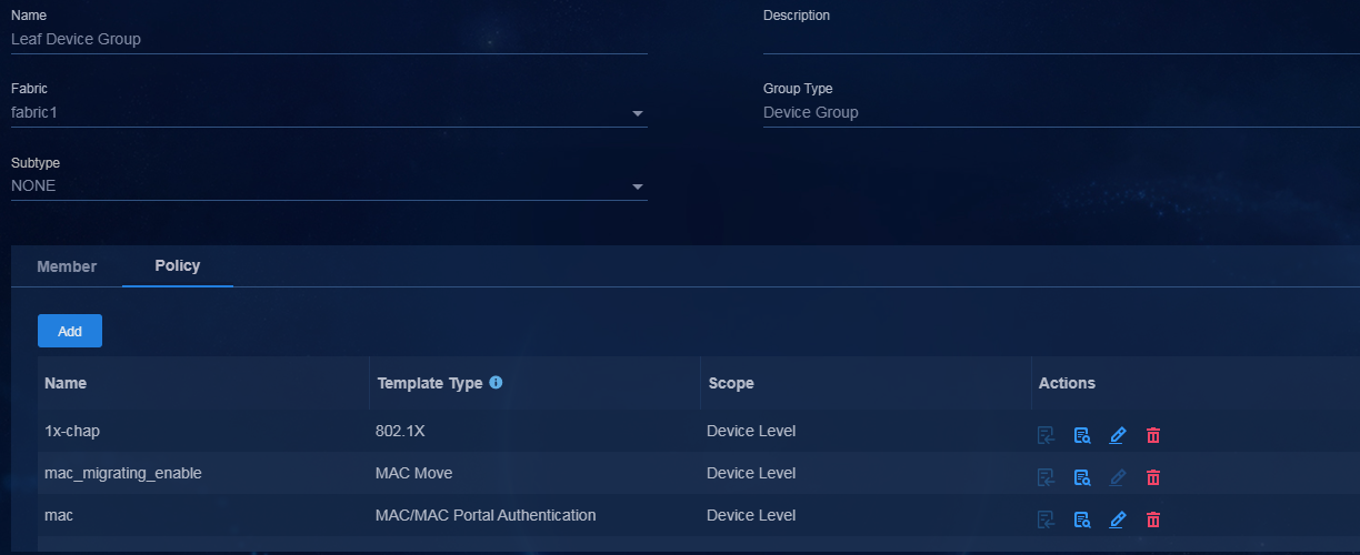
This section describes only specific authentication template settings. For other settings required by user onboarding, see AD-Campus 6.2 Basic Configuration Guide. After completing the configuration, users in different isolation domains can use the associated EIA servers for coming online through authentication.
|
|
IMPORTANT: · As a best practice, use hierarchical EIA deployment when multiple isolation domains exist. · Deploy a separate DHCP server for each of multiple isolation domains. |
Configure the multi-campus BYOD service
This chapter describes only the procedure of IP policy BYOD service configuration when multiple campuses share one EIA server. For more information about BYOD parameters, see MAC Portal authentication in AD-Campus 6.2 Basic Configuration Guide.
The configuration workflow is as follows:
1. In the multi-campus scenario, create a BYOD Layer 2 network domain and BYOD security group for each campus.
2. Create a BYOD access policy and access location for each campus.
3. Associate BYOD access services with access policies and security groups of the corresponding campuses based on the campus access locations.
4. Associate BYOD users with BYOD access services of the corresponding campuses.
|
|
NOTE: · This section describes IP policy multi-campus BYOD service configuration. · The multi-campus group policy BYOD service configuration is the same as the single-campus BYOD service configuration. A unique microsegment ID is assigned. For more information, see AD-Campus 6.2 Basic Configuration Guide. |
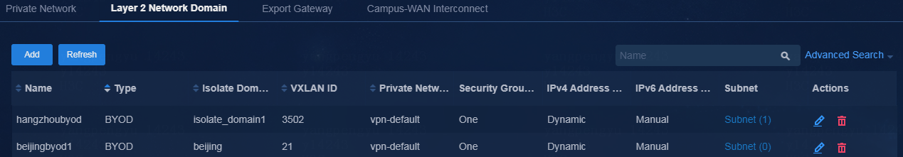
Create BYOD Layer 2 network domains in the multi-campus scenario
Create a separate BYOD Layer 2 network domain for each isolation domain. For more information, see BYOD Layer 2 network domain creation in AD-Campus 6.2 Basic Configuration Guide.
Figure 33 Creating BYOD Layer 2 network domains
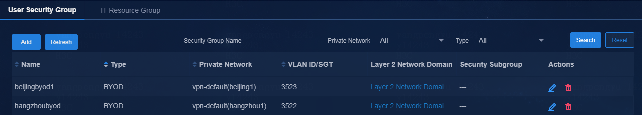
Create BYOD security groups in the multi-campus scenario
Create a separate BYOD security group for each isolation domain. For more information, see BYOD security group creation in AD-Campus 6.2 Basic Configuration Guide.
Figure 34 Creating BYOD security groups
Create access services in the multi-campus scenario
1. Create a separate BYOD access policy and access location for each campus. For more information, see in AD-Campus 6.2 Basic Configuration Guide.
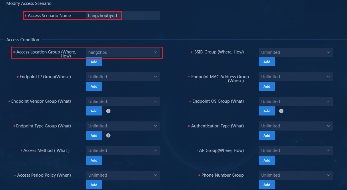
2. Create BYOD access services, and associate the BYOD access services with access policies and security groups of the corresponding campuses based on their access locations.
Figure 35 Creating an access service
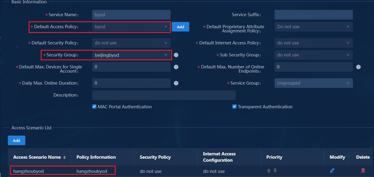
Figure 36 Adding an access scenario

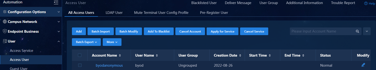
3. Create a BYOD user associated with a BYOD access service.
Figure 37 Associating a BYOD access service
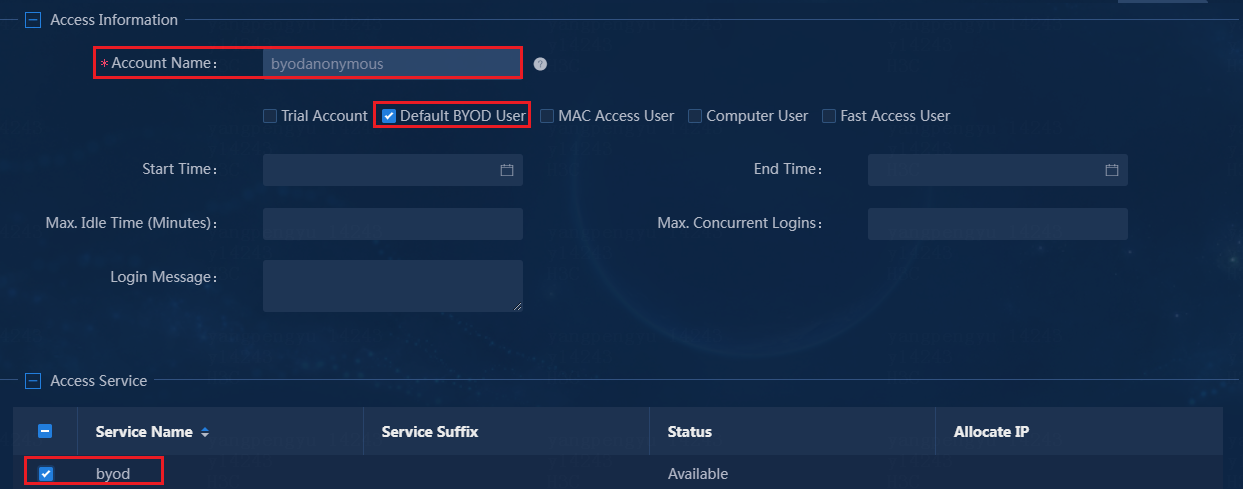
Figure 38 Viewing the BYOD user
Configure fabric interconnection through a management switch
Network topology
In the network, multiple fabrics are connected through a Layer 3 management switch. The management switch can be connected to the spines (EDs) in the fabrics through Layer 3 subinterfaces or different VLANs. All control traffic and service traffic are forwarded through the spine (ED) devices (core switches with high performance) at the headquarters.
Figure 39 Network diagram
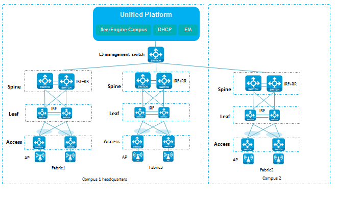
Table 2 IP and VLAN resources
|
Item |
Example |
Description |
|
Fabric1 VLAN 1 network (gateway) |
120.1.0.0/24(120.1.0.1) |
VLAN 1 network address for automated onboarding. |
|
Fabric2 VLAN 1 network (gateway) |
111.0.0.0/24(111.0.0.11) |
VLAN 1 network for automated onboarding. |
|
Fabric3 VLAN 1 network (gateway) |
122.0.0.0/24(122.0.0.50) |
VLAN 1 network address for automated onboarding. |
|
Fabric1 VLAN 4094 network (gateway) |
130.1.0.0/24 (130.1.0.1) |
VLAN 4094 network address for communication between the controller and devices |
|
Fabric2 VLAN 4094 network (gateway) |
111.0.9.0/24 (111.0.9.11) |
VLAN 4094 network address for communication between the controller and devices |
|
Fabric3 VLAN 4094 network (gateway) |
122.0.1.0/24 (122.0.1.50) |
VLAN 4094 network address for communication between the controller and devices |
|
VLAN 70 network (gateway) |
120.1.0.0/24 (120.1.0.1) |
VLAN 1 gateway address of Fabric1 in a different VLAN mode for automated onboarding |
|
VLAN 71 network (gateway) |
111.0.0.0/24 (111.0.0.11) |
VLAN 1 gateway address of Fabric2 in a different VLAN mode for automated onboarding |
|
VLAN 72 network (gateway) |
122.0.0.0/24 (122.0.0.50) |
VLAN 1 gateway address of Fabric3 in a different VLAN mode for automated onboarding |
|
Fabric1 underlay IP network address |
200.1.1.0/24 |
Network address of the loopback interfaces on spines and leafs |
|
Fabric2 underlay IP network address |
20.0.0.0/24 |
Network address of the loopback interfaces on spines and leafs |
|
Fabric3 underlay IP network address |
12.0.0.0/24 |
Network address of the loopback interfaces on spines and leafs |
|
Fabric1 VLAN 11 |
11.11.0.0/24 |
Interconnection between ED and the Layer 3 management switch |
|
Fabric1 VLAN 12 |
12.12.0.0/24 |
Interconnection between ED and the Layer 3 management switch |
|
Fabric1 VLAN 13 |
11.13.0.0/24 |
Interconnection between ED and the Layer 3 management switch |
|
vDHCP node IP |
Node 1: 110.1.0.105 Node 2: 110.1.0.106 |
IP addresses of the two nodes used by the vDHCP server. |
|
|
IMPORTANT: The Layer 3 management switch used for interconnection acts only as the management device for the controller. The fabric interconnection and access traffic between fabrics require using separate egress routers. |
Procedure
Configure the management switch
This chapter describes only the configuration of fabric interconnection through a Layer 3 management switch. It mainly involves the configuration of the Layer 3 management switch that is different than the spines (EDs). The controller configuration is similar to that in the previous chapters.
Method 1: Interconnection through Layer 3 subinterfaces
· Configure the Layer 3 interface on the management switch connected to the spine in Fabric1.
#
interface Ten-GigabitEthernet1/4/22
port link-mode route //Layer 3 interface connected to VLAN 1 in Fabric1
ip address 120.1.0.1 255.255.255.0 //Gateway of VLAN 1 in Fabric1
dhcp select relay //DHCP relay agent settings
dhcp relay server-address 110.1.0.105
dhcp relay server-address 110.1.0.106
#
#
interface Ten-GigabitEthernet1/4/22.4094 //Layer 3 interface connected to VLAN 4094 in Fabric1
ip address 130.1.0.1 255.255.255.0 //Gateway of VLAN 4094 in Fabric1
#
· Configure the Layer 3 interface on the management switch connected to the spine in Fabric2.
#
interface Ten-GigabitEthernet1/4/23
port link-mode route //Layer 3 interface connected to VLAN 1 in Fabric2
ip address 111.0.0.11 255.255.255.0 //Gateway of VLAN 1 in Fabric2
dhcp select relay //DHCP relay agent settings
dhcp relay server-address 110.1.0.105
dhcp relay server-address 110.1.0.106
#
#
interface Ten-GigabitEthernet1/4/23.4094 //Layer 3 interface connected to VLAN 4094 in Fabric2
ip address 111.0.9.11 255.255.255.0 //Gateway of VLAN 4094 in Fabric2
#
· Configure the Layer 3 interface on the management switch connected to the spine in Fabric3.
#
interface Ten-GigabitEthernet1/4/24
port link-mode route //Layer 3 interface connected to VLAN 1 in Fabric3
ip address 122.0.0.50 255.255.255.0 //Gateway of VLAN 1 in Fabric3
dhcp select relay //DHCP relay agent settings
dhcp relay server-address 110.1.0.105
dhcp relay server-address 110.1.0.106
#
#
interface Ten-GigabitEthernet1/4/24.4094 //Layer 3 interface connected to VLAN 4094 in Fabric3
ip address 122.0.1.50 255.255.255.0 //Gateway of VLAN 4094 in Fabric3
#
Method 2: Interconnection through VLAN interfaces
#
Vlan 70
Vlan 71
Vlan 72
#
# Configure the VLAN interface on management switch connected to the spines.
#
interface Ten-GigabitEthernet1/4/22 //Interface connected to the spine in Fabric1
port link-mode bridge
port link-type trunk
port trunk permit vlan 1 11 70 4094
port trunk pvid vlan 70
#
#
interface Ten-GigabitEthernet1/4/23 //Interface connected to the spine in Fabric2
port link-mode bridge
port link-type trunk
port trunk permit vlan 1 12 71 4094
port trunk pvid vlan 71
#
#
interface Ten-GigabitEthernet1/4/25 //Interface connected to the spine in Fabric3
port link-mode bridge
port link-type trunk
port trunk permit vlan 1 13 72 4094
port trunk pvid vlan 72
#
#
interface Vlan-interface70 //Gateway of VLAN 1 in Fabric1
ip address 120.1.0.1 255.255.255.0
dhcp select relay
dhcp relay server-address 110.1.0.105
dhcp relay server-address 110.1.0.106
#
#
interface Vlan-interface71 //Gateway of VLAN 1 in Fabric2
ip address 111.0.0.11 255.255.255.0
dhcp select relay
dhcp relay server-address 110.1.0.105
dhcp relay server-address 110.1.0.106
#
#
interface Vlan-interface72 //Gateway of VLAN 1 in Fabric3
ip address 122.0.0.50 255.255.255.0
dhcp select relay
dhcp relay server-address 110.1.0.105
dhcp relay server-address 110.1.0.106
#
#
interface Vlan-interface4094 //Assign secondary IP addresses to VLAN-interface 4094
ip address 130.1.0.1 255.255.255.0 //Gateway of VLAN 4094 in Fabric1
ip address 111.0.9.11 255.255.255.0 sub //Gateway of VLAN 4094 in Fabric2
ip address 122.0.1.50 255.255.255.0 sub //Gateway of VLAN 4094 in Fabric3
#
Configure multi-campus automation
For more information about automation configuration, see AD-Campus 6.2 Automation Configuration Guide.
Configure Layer 3 connectivity between EDs of multiple fabrics in multiple campuses
Configure the ED and management switch settings for Fabric1
· Configure OSPF and DCI settings for the ED (spine)
#
ospf 2
area 0.0.0.0
network 200.1.1.254 0.0.0.0 //Advertise the IP address of LoopBack0.
#
vlan 11
#
interface Vlan-interface11
ip address 11.11.0.2 255.255.255.0
ospf 2 area 0.0.0.0
dci enable
#
· Configure OSPF settings for the management switch
¡ Layer 3 subinterface mode:
#
interface Ten-GigabitEthernet1/4/22.11 //Layer 3 interface connected to the ED in Fabric1.
ip address 11.11.0.1 255.255.255.0
ospf 2 area 0.0.0.0
#
¡ VLAN interface mode:
#
vlan 11
#
interface Ten-GigabitEthernet1/4/22 //Interface of the ED and management switch.
port link-mode bridge
port link-type trunk
port trunk permit vlan 1 11 70 4094
port trunk pvid vlan 70
#
interface Vlan-interface11
ip address 11.11.0.1 255.255.255.0
ospf 2 area 0.0.0.0
#
Configure the ED and management switch settings for Fabric2
· Configure OSPF and DCI settings for the ED (spine)
#
ospf 2
area 0.0.0.0
network 20.0.0.254 0.0.0.0 //Advertise the IP address of LoopBack0.
#
vlan 12
#
interface Vlan-interface12
ip address 12.12.0.2 255.255.255.0
ospf 2 area 0.0.0.0
dci enable
#
· Configure OSPF settings for the management switch
¡ Layer 3 subinterface mode:
#
interface Ten-GigabitEthernet1/4/23.12 //Layer 3 interface connected to the ED in Fabric1.
ip address 12.12.0.1 255.255.255.0
ospf 2 area 0.0.0.0
#
¡ VLAN interface mode:
#
vlan 12
#
interface Ten-GigabitEthernet1/4/23 //Interface of the ED and management switch.
port link-mode bridge
port link-type trunk
port trunk permit vlan 1 12 71 4094
port trunk pvid vlan 71
#
interface Vlan-interface12
ip address 12.12.0.1 255.255.255.0
ospf 2 area 0.0.0.0
#
Configure the ED and management switch settings for Fabric3
· Configure OSPF and DCI settings for the ED (spine)
#
ospf 2
area 0.0.0.0
network 12.0.0.254 0.0.0.0 //Advertise the IP address of LoopBack0.
#
vlan 13
#
interface Vlan-interface13
ip address 11.13.0.2 255.255.255.0
ospf 2 area 0.0.0.0
dci enable
#
· Configure OSPF settings for the management switch
¡ Layer 3 subinterface mode:
#
interface Ten-GigabitEthernet1/4/24.13 //Layer 3 interface connected to the ED in Fabric1.
ip address 11.13.0.1 255.255.255.0
ospf 2 area 0.0.0.0
#
¡ VLAN interface mode:
#
vlan 13
#
interface Ten-GigabitEthernet1/4/24 //Interface of the ED and management switch.
port link-mode bridge
port link-type trunk
port trunk permit vlan 1 13 72 4094
port trunk pvid vlan 72
#
interface Vlan-interface13
ip address 11.13.0.1 255.255.255.0
ospf 2 area 0.0.0.0
#
Configure fabric connection settings
Details not shown. For more information, see "Configure fabric connection for the controller." After configuration, verify your settings.
Restrictions and guidelines
1. Fabric interconnection through devices of the same VCF role will result in device reboot due to automatic stacking, affecting services. To resolve this issue, incorporate the device in the fabric onboarded first, manually disable LLDP for the interconnected interface on the device, and then directly connect the device in another fabric. After automated incorporation of all devices, disable the automation feature on the devices.
¡ Disable LLDP on the interface:
interface Ten-GigabitEthernet1/2/21
undo lldp enable
¡ Disable device automation:
vcf-fabric underlay pause
2. All control traffic and service traffic in this document are forwarded through the spine (ED) devices (core switches with high performance) at the headquarters.
3. The core spine (ED) in each fabric is directly connected to the egress router. VLAN 1 and VLAN 4094 of the spines are directly connected to the egress router. The gateways for VLAN 1 and VLAN 4094 are configured through Layer 2 interfaces or Layer 3 subinterfaces on the egress router. If the egress router does not support Layer 2 interfaces or Layer 3 subinterfaces, you need to connect a device that supports VLAN 1 and VLAN 4094 gateway configuration to the spine (ED) and egress router.
4. Other fabrics in the network connect to the management area through the spine (ED) in Fabric 1. The spine (ED) in Fabric 1 performs automated onboarding first. The devices in the two fabrics perform automated onboarding in sequence.
5. For more information about multi-campus service configuration, see AD-Campus 6.2 Basic Configuration Guide.
6. In the current software version, S5560X and S6520X switches cannot act as EDs.
7. The single-campus multi-fabric scenario requires interconnection of VXLANs. When users move across different fabrics, the associated network segment does not change, and a bypass issue might exist for the return traffic from the external network. To avoid this issue, as a best practice, use the multi-campus multi-fabric scenario.
