
- Released At: 13-09-2023
- Page Views:
- Downloads:
- Table of Contents
- Related Documents
-
AD-Campus 6.2
IPv6 Service Configuration Guide
Document version: 5W100-20230221
Copyright © 2023 New H3C Technologies Co., Ltd. All rights reserved.
No part of this manual may be reproduced or transmitted in any form or by any means without prior written consent of New H3C Technologies Co., Ltd.
Except for the trademarks of New H3C Technologies Co., Ltd., any trademarks that may be mentioned in this document are the property of their respective owners.
This document provides generic technical information, some of which might not be applicable to your products.
The information in this document is subject to change without notice.
Contents
IPv6 service configuration flowchart
Resource and IP address planning
Configure the IPv6 service for managed devices
Configure automated device deployment
Configure the Microsoft DHCPv6 server
IPv6 service configuration flowchart
Resource and IP address planning
Install vDHCP on Unified Platform
Configure automated deployment of pure IPv6 devices
Configure the Layer 3/2 architecture
IRF stacking of Access devices
Add a DHCPv6 server in the isolation domain
Configure authentication terminals
Introduction
With the advancement of IPv6, campus network users have a high demand for IPv6 services. Therefore, H3C added the IPv6 service related functions, including IPv6 device management, automated IPv6 device deployment, and IPv6 authentication, to the AD-Campus solution.
At present, the controller manages IPv6 services in the following two modes:
· Use IPv4 as the management network and IPv6 as the service network.
· Use IPv6 as the management network and IPv6 as the service network.
For procedures to configure the IPv6 service in the two networking modes, see "IPv4 network" and "IPv6 network".
IPv4 network
Typical networking
Network diagram
Figure 1 Network diagram
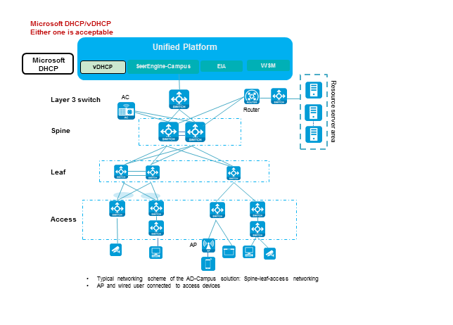
Devices are still managed by the controller through IPv4 addresses. Compared with standard IPv4 networking, the networking adds Microsoft DHCPv6 server and Microsoft DHCP/vDHCP. Microsoft DHCPv6 supports only loose coupling, while vDHCP supports both tight coupling and high availability (HA).
Configuration process
Devices in the network are managed by the controller through IPv4 addresses. The IPv6 service can be manually configured or automatically deployed by the controller based on the following procedures:
IPv6 configuration for managed devices
1. The controller manages devices through IPv4 addresses.
2. Configure the IPv6 service on the devices manually.
3. Configure the IPv6 service on the controller page.
4. Configure the DHCPv6 server.
5. Configure the IPv6 security group.
6. A user comes online after authentication and obtains the IPv6 address.
Automated device deployment
1. Configure the IPv6 service on the controller page.
2. Start automated device deployment, during which the controller deploys the IPv6 configuration on the devices.
3. Configure the DHCPv6 server.
4. Configure the IPv6 security group.
5. A user comes online after authentication and obtains the IPv6 address.
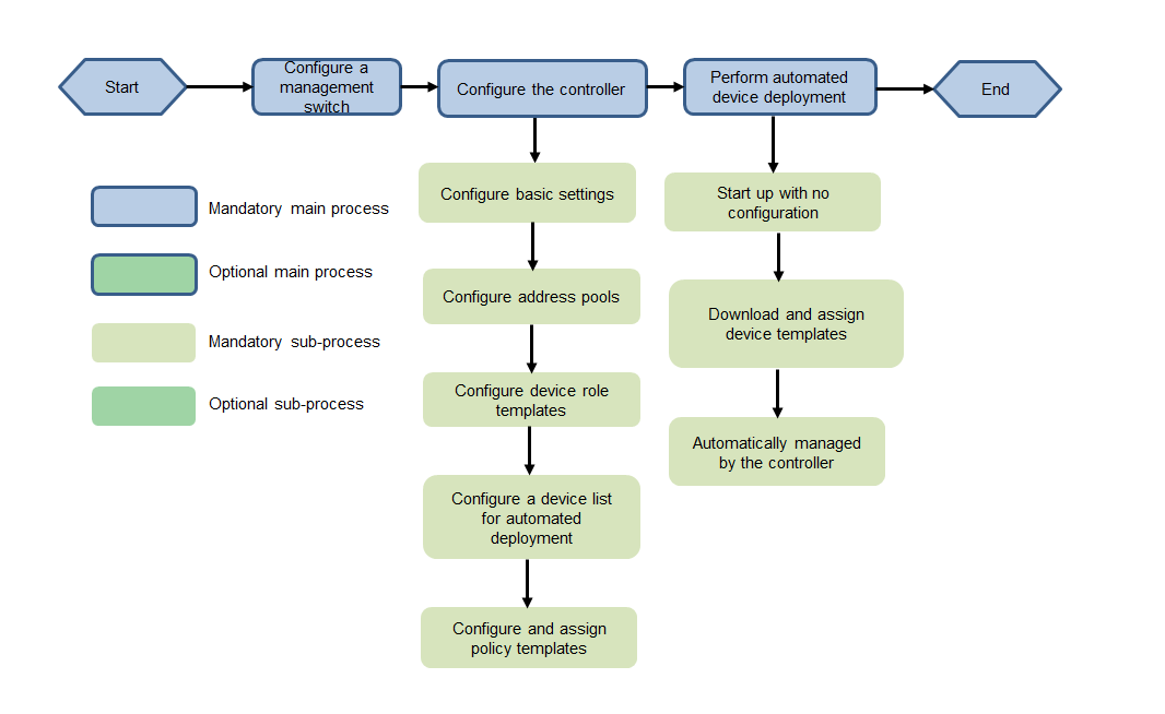
IPv6 service configuration flowchart
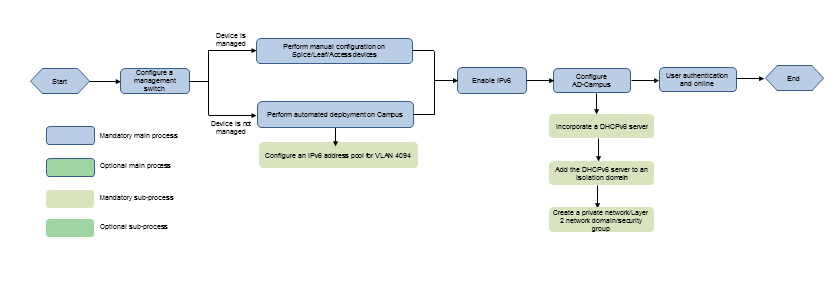
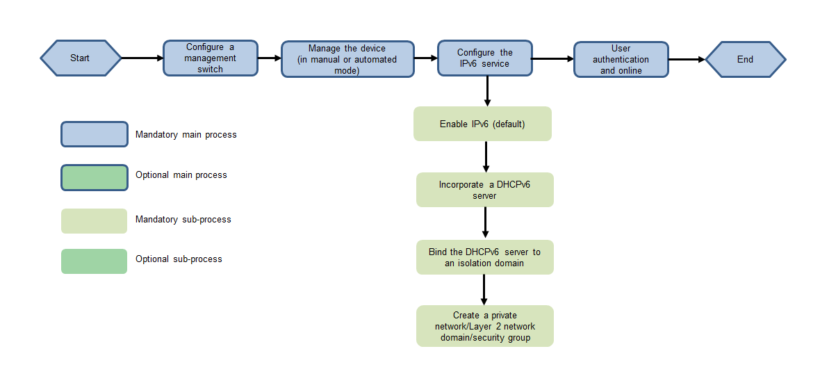
Figure 2 IPv6 service configuration flowchart
Configure the IPv6 service
Resource and IP address planning
Table 1 IP address planning
|
Item |
Example |
Description |
|
VLAN 1 network segment (gateway) |
120.1.0.0/24 (120.1.0.1) |
VLAN 1 network for automated deployment |
|
VLAN 4094 network segment (gateway) |
130.1.0.0/24 (130.1.0.1) |
VLAN 4094 network for communication between the controller and devices |
|
VLAN 30 network segment (gateway) |
100.1.0.0/24 (100.1.0.1) |
Network segment used by Unified Platform for communication with PCs |
|
VLAN 1010 network segment (gateway) |
110.1.0.0/24 (110.1.0.1) |
Network segment used by SeerEngine-Campus and vDHCP for communication between the controller and PCs (configured when SeerEngine-Campus uses an independent network adapter) |
|
Network segment of the Underlay IP address |
200.1.1.0/24 |
Network segment of the IP addresses of the loopback interfaces on Spine and Leaf devices |
|
Unified Platform northbound service IP address |
100.1.0.100 |
The address of logging in to Unified Platform |
|
EIA |
100.1.0.100 |
IP address of the EIA server |
|
SeerEngine-Campus cluster IP address |
110.1.0.100 |
IP address of the SeerEngine-Campus cluster |
|
SeerEngine-Campus node IP address |
Node 1: 110.1.0.101 Node 2: 110.1.0.102 Node 3: 110.1.0.103 |
IP addresses of the three nodes in the SeerEngine-Campus cluster |
|
vDHCP cluster IP address |
110.1.0.104 |
Cluster IP address of the vDHCP server (not used actually) |
|
vDHCP node IP address |
Node 1: 110.1.0.105 Node 2: 110.1.0.106 |
IP addresses of the two nodes in the vDHCP server |
|
VLAN 4094 IPv6 network segment (gateway) |
133::/64 (133::1) |
VLAN 4094 IPv6 network for communication between the controller and devices |
|
Microsoft DHCPv6 network segment (gateway) |
130::/64 (130::AAAA) |
Network segment of the Microsoft DHCP server for communication with Unified Platform |
Configure the IPv6 service for managed devices
This scenario is also applicable to manual management on new devices.
Configure the Layer 3 switch
1. Add the IPv6 gateway address in the IP address pool to VLAN-interface 4094 of the Layer 3 switch.
#
interface Vlan-interface4094
ip address 130.1.0.1 255.255.255.0
ipv6 address 133::1/64
#
2. Configure the static route.
Configure the static routing or dynamic routing protocol for interconnection between the user and the server (DHCPv6 or EIA V7) after the user obtains the IPv6 address.
ipv6 route-static :: 0 133::2 // Configure a default route whose next hop is the IPv6 address of VSI-interface 4094 of the Spine device.
Configure Spine devices
1. Configure the IPv6 address of VSI-interface 4094.
#
interface Vsi-interface4094
ip binding vpn-instance vpn-default
ip address 130.1.0.2 255.255.255.0
local-proxy-arp enable
ipv6 address 133:: 2/64
local-proxy-nd enable
#
2. Configure the VPN.
ip vpn-instance vpn-default
route-distinguisher 1:1
vpn-target 1:1 import-extcommunity
vpn-target 1:1 export-extcommunity
#
address-family ipv6
vpn-target 1:1 import-extcommunity
vpn-target 1:1 export-extcommunity
#
3. Configure the BGP.
bgp 100
ip vpn-instance vpn-default
#
address-family ipv6 unicast
import-route direct
import-route static
#
4. Configure the static route.
Configure a static route to the server with the next hop being the IPv6 address of VLAN 4094 of the Layer 3 switch.
ipv6 route-static vpn-instance vpn-default 130:: 64 133::1
// The destination IP address resides in the IPv6 network segment of the server.
5. Disable ND learning on VXLAN tunnels globally.
vxlan tunnel nd-learning disable
6. Enable the IPv6 function for VSI-interface 4092.
interface Vsi-interface4092
ip binding vpn-instance vpn-default
ip address unnumbered interface Vsi-interface4094
ipv6 address auto link-local
l3-vni 4092
#
Configure Leaf devices
1. Configure VSI-interface 4094.
#
interface Vsi-interface4094
ip binding vpn-instance vpn-default
ip address 130.1.0.3 255.255.255.0
local-proxy-arp enable
arp proxy-send enable
ipv6 address 133:: 3/64
local-proxy-nd enable
#
2. Configure the VPN.
ip vpn-instance vpn-default
route-distinguisher 1:1
vpn-target 1:1 import-extcommunity
vpn-target 1:1 export-extcommunity
#
address-family ipv6
vpn-target 1:1 import-extcommunity
vpn-target 1:1 export-extcommunity
#
3. Configure the BGP.
bgp 100
ip vpn-instance vpn-default
#
address-family ipv6 unicast
import-route direct
import-route static
#
4. Configure the static route.
Configure a static route to the server with the next hop being the IPv6 address of VLAN 4094 of the Layer 3 switch.
ipv6 route-static vpn-instance vpn-default 130::64 133::1 // The destination IP address is the IPv6 network segment of the server.
5. Configure DHCP snooping globally.
ipv6 dhcp snooping enable vlan 2 to 4094
6. Disable ND learning on VXLAN tunnels globally.
vxlan tunnel nd-learning disable
7. Enable the IPv6 function for VSI-interface 4092.
interface Vsi-interface4092
ip binding vpn-instance vpn-default
ip address unnumbered interface Vsi-interface4094
ipv6 address auto link-local
l3-vni 4092
#
8. Configure DHCP snooping under the VSI VXLAN 4094 instance.
#
vsi vxlan4094
gateway vsi-interface 4094
vxlan 4094
evpn encapsulation vxlan
mac-advertising disable
arp mac-learning disable
route-distinguisher auto
vpn-target auto export-extcommunity
vpn-target auto import-extcommunity
dhcp snooping trust tunnel
ipv6 dhcp snooping trust tunnel
#
Configure the Access device
1. Configure VLAN-interface 4094.
#
interface Vlan-interface4094
ip address 130.1.0.4 255.255.255.0
ipv6 address 133:: 4/64
#
2. Configure the static route.
When the connection between the spine and Unified Platform is a Layer 3 connection, you need to configure static routes to the server, with the next hop being the IPv6 address of the VLAN-interface 4094 on the L3 switch.
ipv6 route-static 130::64 133::1 // The destination IP address resides in the IPv6 network segment of the server.
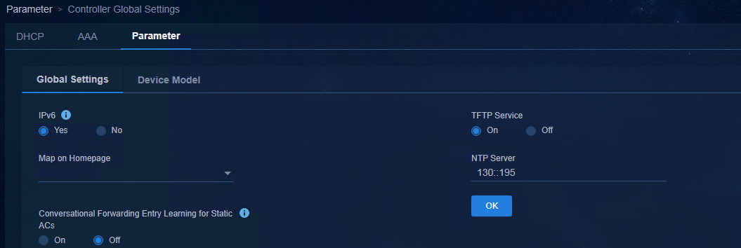
Enable IPv6 on the controller page
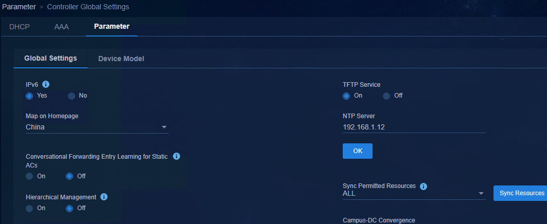
Access Automation > Campus Network > Network Parameters > Parameter > Controller Global Settings page, and set IPv6 to Yes.
Figure 3 Enabling IPv6
Configure automated device deployment
For automated device deployment, you only need to add the following configuration on the basis of IPv4.
Configure the Layer 3 switch
1. Add the IPv6 gateway address in the IP address pool to VLAN-interface 4094 on the Layer 3 switch.
#
interface Vlan-interface4094
ip address 130.1.0.1 255.255.255.0
ipv6 address 133:: 1/64
#
2. Configure the static route.
Configure the static routing or dynamic routing protocol for interconnection between the user and the server after the user obtains the IPv6 address.
ipv6 route-static :: 0 133::2 // Configure a default route whose next hop is the IPv6 address of VSI-interface 4094 of the Spine device.
Configure the IPv6 service on the controller page
1. Create an IPv6 address pool for VLAN 4094. Access Automation > Campus Network > Device Groups page, and click IP Address Pools.
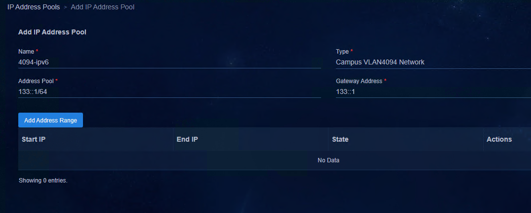
2. Click Add. Configure the IP address pool as shown in the following figure. Click OK to save the configuration.
¡ Name: Enter the name.
¡ Type: Select Campus VLAN4094 Network.
¡ Address Pool: Enter the address pool.
¡ Gateway Address: Enter the gateway address.
Figure 4 Adding an IP address pool
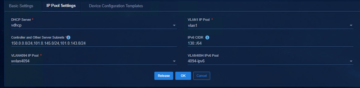
3. Create an automation template. When you create an automation template, add the IPv6 address pool of VLAN 4094 in the address pool settings, and add the IPv6 address of the DHCP server to the IPv6 network segment.
a. Access Automation > Campus
Network > Fabrics page, and click Automatic Deployment.
Select Legacy Automated Deployment and select the Automation
Templates tab and click the ![]() icon in the Actions
column corresponding to the template name in the list. Select the IP Pool
Settings tab to configure the IP address pool. Parameters are described as
follows:
icon in the Actions
column corresponding to the template name in the list. Select the IP Pool
Settings tab to configure the IP address pool. Parameters are described as
follows:
- VLAN4094 IPv6 Pool: Select the previously created IP address pool.
- IPv6 CIDR: Specify the IPv6 address segment of the server for communication with users. During automated device deployment, the controller deploys the static route of this network segment to the devices.
Figure 5 Setting the IP address pool
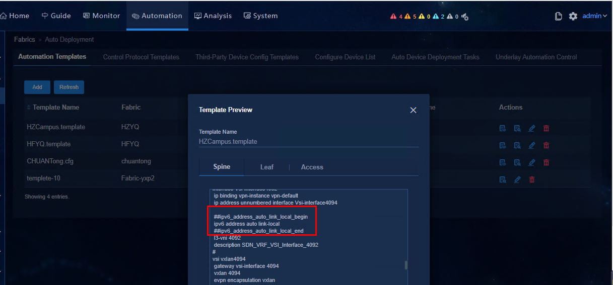
b. After completing the configuration, click OK
to save the settings and go back to the automation template page. Click the ![]() icon
in the Actions column of the corresponding template name to view the
added IPv6 configurations, as shown in the figure below.
icon
in the Actions column of the corresponding template name to view the
added IPv6 configurations, as shown in the figure below.
Figure 6 Previewing the template
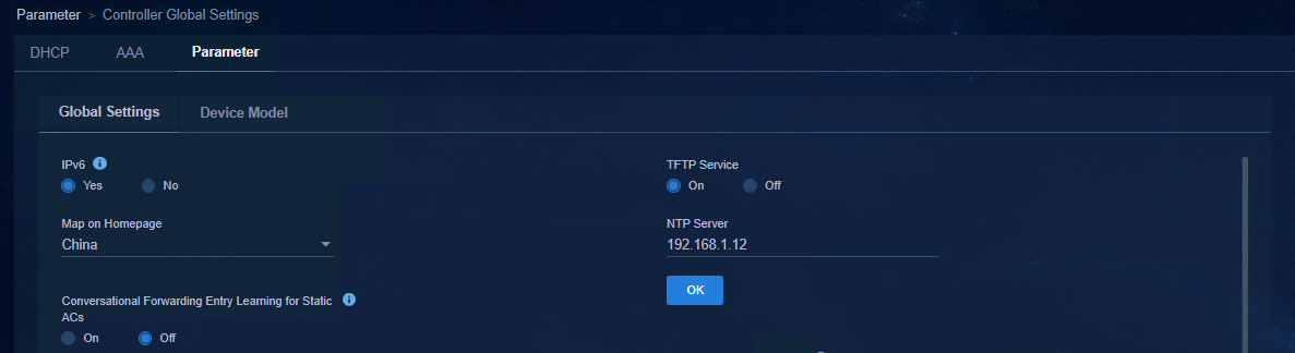
Enable IPv6 on the controller page
Access Automation > Campus Network > Network Parameters > Parameter > Global Settings page, and set IPv6 to Yes.
Figure 7 Enabling IPv6
Configure the DHCPv6 server
Configure the Microsoft DHCPv6 server
Install Microsoft DHCP
For details, see the section about installing Microsoft DHCP services in AD-Campus 6.2 Tight Microsoft DHCP Management Configuration Guide.
Incorporate the DHCPv6 server to the controller
|
|
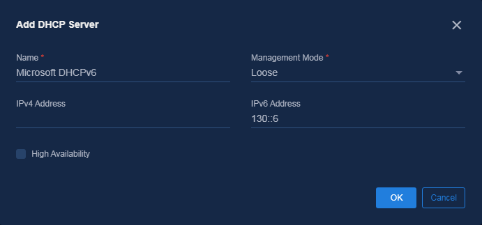
IMPORTANT: Select Loose as the management mode and do not select High Available because this solution does not support it. |
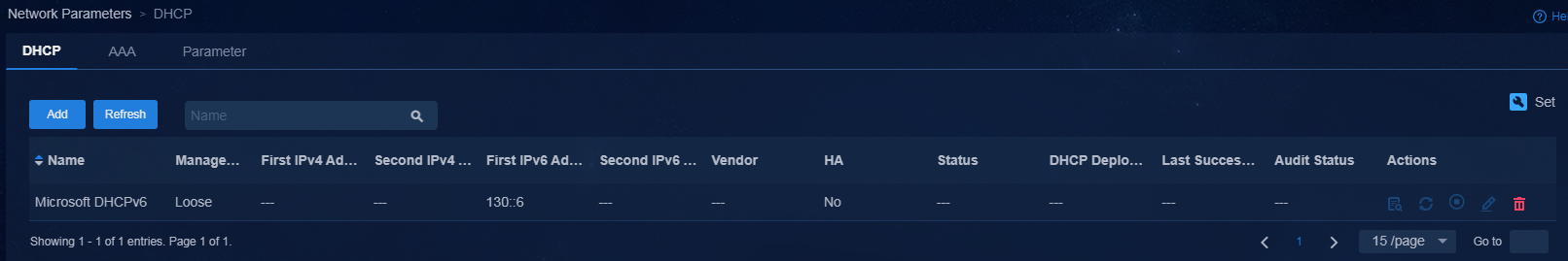
Access Automation > Campus Network > Network Parameters > DHCP page and click Add. Configure the Microsoft DHCP server with the configuration shown in the figure below.
· Name: Enter the name.
· Management Mode: Select Loose.
· IPv6 Address: Enter the IPv6 address.
Figure 8 Adding the DHCP server
After completing the configuration, click OK. The newly added DHCP server is displayed in the DHCP list.
Figure 9 Viewing the DHCP server
Create an IPv6 scope for the security group
|
|
CAUTION: · No superscope needs to be created for IPv6. · At present, the DHCPv6 server only supports loose coupling and does not support the primary/backup mode. The scope of the security group can only be added manually on the DHCP server. |
In a typical networking, users obtain IPv4 addresses from vDHCP, so it is not necessary to configure the IPv4 scope of the security group on the Microsoft DHCP server.
To create an IPv6 scope for the security group:
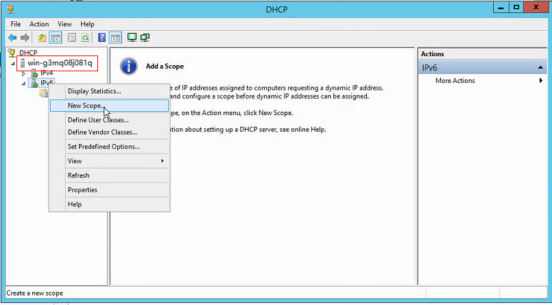
1. In the DHCP window, select DHCP > win-g3mq08j081q > IPv6 and then click IPv6. Among which, win-g3mq08j081q is used as an example and can be adjusted according to the actual path. Select New Scope from the shortcut menu.
Figure 10 Creating a new scope
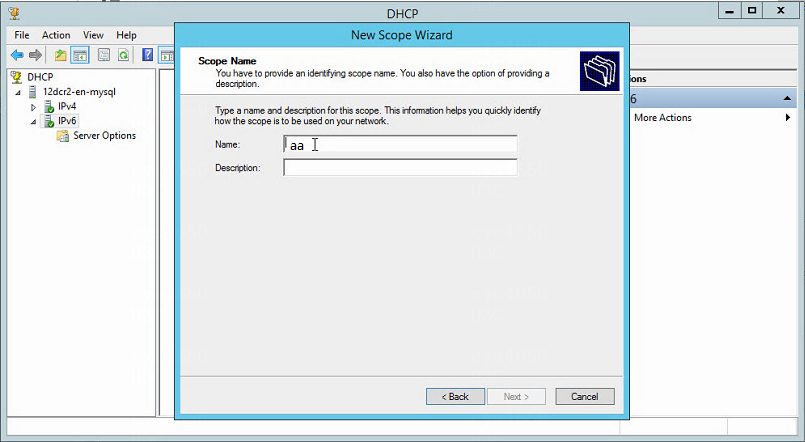
2. Enter the name and description, and click Next.
Figure 11 Specifying the scope name
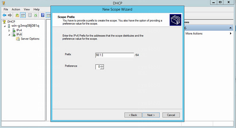
3. Access the Scope Prefix page, enter the IPv6 prefix for the addresses that the scope distributes, and click Next.
Figure 12 Specifying the scope prefix
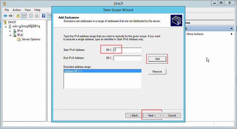
4. Access the Add Exclusions page, enter the IPv6 address range (including the gateway address) that you want to exclude for the given scope, and click Add. The excluded address range is displayed in Excluded address range. Click Next.
Figure 13 Adding exclusions
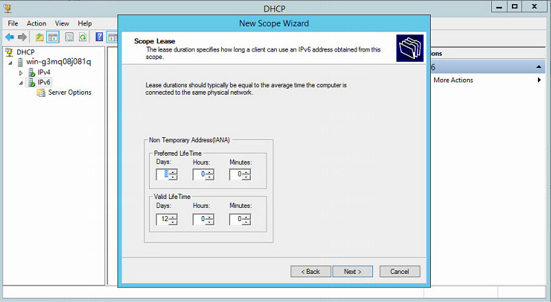
5. Access the Scope Lease page. The ranges for the preferred life time and the valid life time of IPv6 addresses are both from 1 minute to 999 days, 23 hours, and 59 minutes. The preferred life time should be less than or equal to the valid life time.
Figure 14 Configuring scope lease
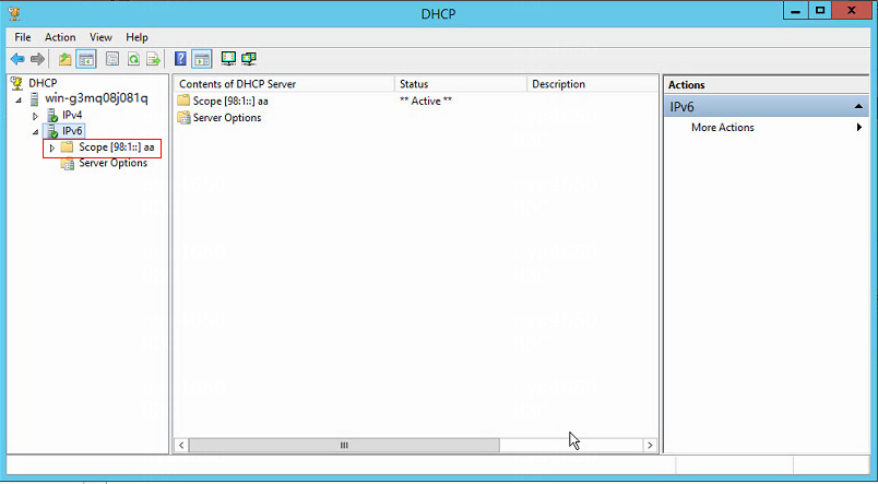
6. Keep the default settings for other parameters, and click Next until the scope is activated, as shown in the following figure.
Figure 15 Scope activated
IPv6 network
Typical networking
Network diagram
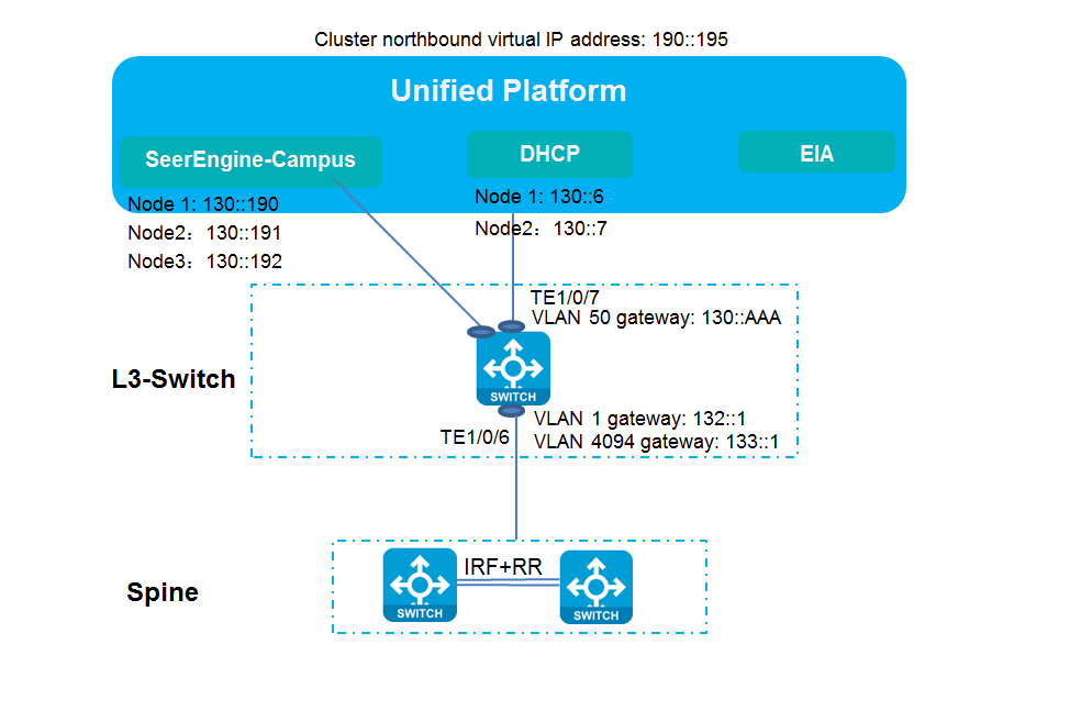
Figure 16 Network diagram

Compared with standard IPv4 networking, the DHCPv6 server is added, and a pure IPv6 address network configuration is used when an IPv6 device is managed (the IP addresses of VLAN-interface 1, VLAN-interface 4094, and loopback interface are all IPv6 addresses).
Configuration process
Devices in the network are managed by the controller through IPv6 addresses and the IPv6 service can be automatically deployed or manually configured based on the following procedures.
Manually configure devices
1. Configure the IPv6 service on the devices manually.
2. Manually incorporate the devices on the controller page.
3. Configure the DHCPv6 server.
4. Configure the IPv6 security group.
5. A user comes online after authentication and obtains the IPv6 address.
Automated device deployment
1. Configure automated device deployment on the controller page (including the configuration of DHCPv6 server).
2. Configure the IPv6 security group.
3. A user comes online after authentication and obtains the IPv6 address.
IPv6 service configuration flowchart
Figure 17 IPv6 service configuration flowchart
Configure the IPv6 service
Resource and IP address planning
Figure 18 IP address planning
|
Item |
Example |
Description |
|
Unified Platform northbound service IP address |
190::195 |
Unified Platform northbound service IP address |
|
EIA |
190::204 |
IP address of the EIA server |
|
SeerEngine-Campus cluster IP address |
130::195 |
IP address of the SeerEngine-Campus cluster |
|
SeerEngine-Campus node IP address |
Node 1: 130::190 Node 2: 130::191 Node 3: 130::192 |
IP addresses of the three nodes in the SeerEngine-Campus cluster |
|
vDHCP |
Node 1: 130::6 Node 2: 130::7 |
IP addresses of the two nodes in the vDHCP server |
|
VLAN 1 gateway |
132::1 |
VLAN 1 gateway for automated deployment |
|
VLAN 4094 gateway |
133::1 |
VLAN 4094 gateway for communication between the controller and devices |
|
VLAN 50 gateway |
130::AAAA |
VLAN 50 gateway for communication with the controller/Unified Platform |
|
VLAN 150 gateway |
190::AAAA |
VLAN 150 gateway for communication between the controller/Unified Platform and PCs |
Typical connection mode
When you deploy SeerEngine-Campus, select the Layer 3 access solution as the connection mode between the Spine device and the controller. This solution allows Unified Platform and SeerEngine-Campus to share a network adapter. You can choose whether to use the network adapter of Unified Platform as required.
Layer 3 access solution: Use one or two network adapters. If you use one network adapter for deployment, SeerEngine-Campus and Unified Platform share the same network adapter. If you use two, the SeerEngine-Campus and Unified Platform use one network adapter respectively.
Install vDHCP on Unified Platform
1. Log in to Unified Platform. On the top navigation bar, click System. From the left navigation pane, select Deployment Management. Click Upload to upload the vDHCP package.
Figure 19 Uploading the vDHCP package
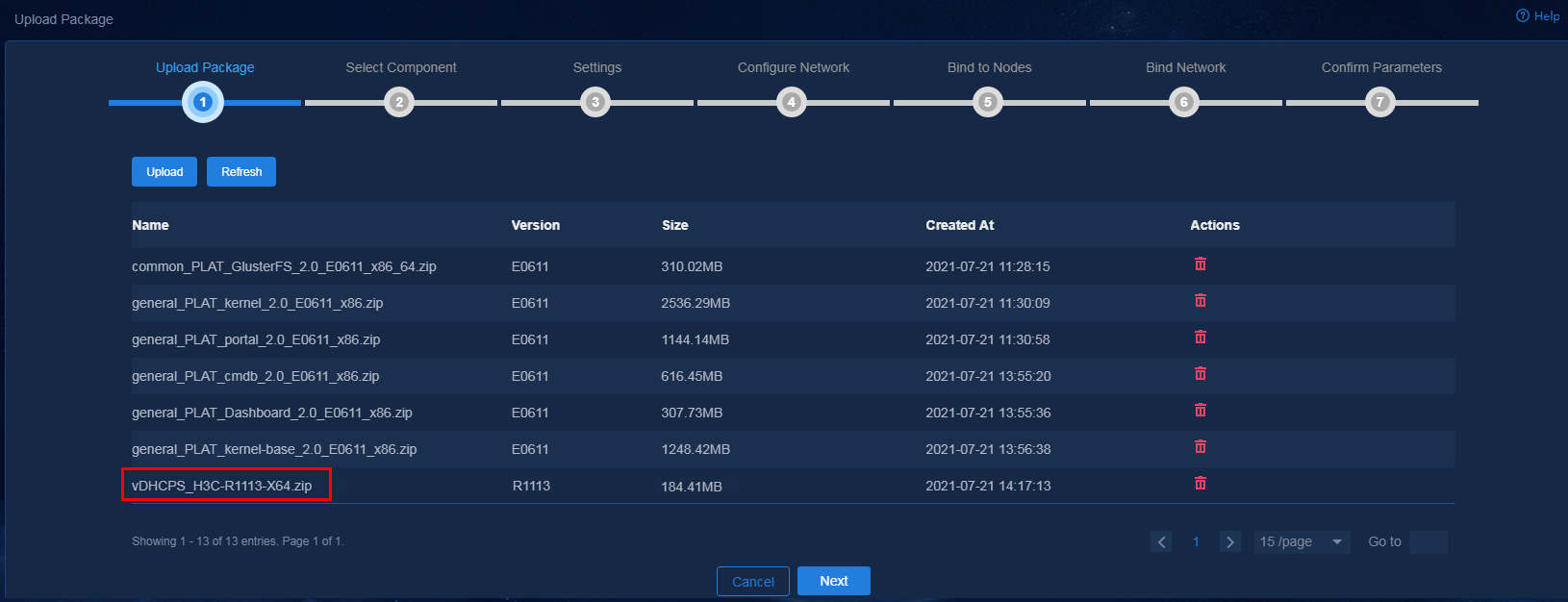
2. Click Next after the package is uploaded.
Figure 20 Selecting the component
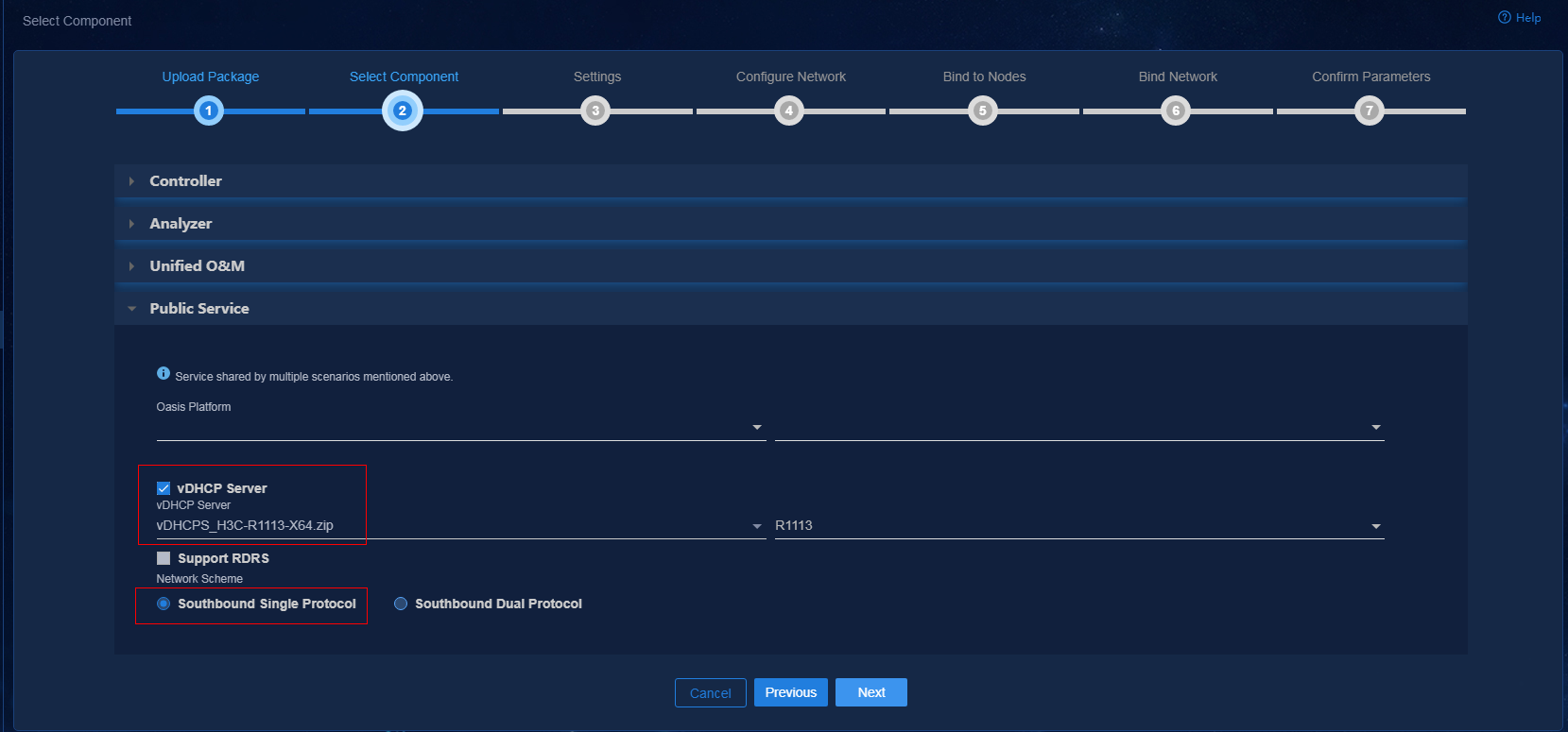
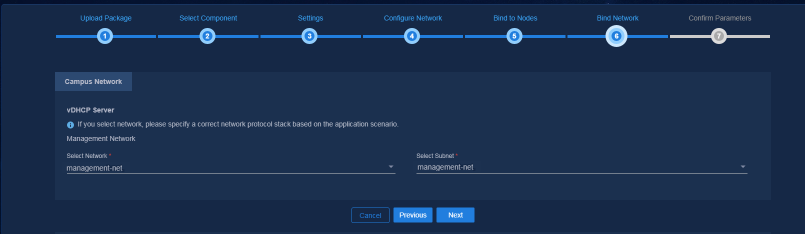
3. On the Select Component page, select the component to be installed and click Next. On the Settings page, click Next directly. On the Configure Network page, create a network and subnet for Layer 3 networking with the same network segment as VLAN 50 to assign IP addresses to the controller and vDHCP.
Figure 21 Configuring the network
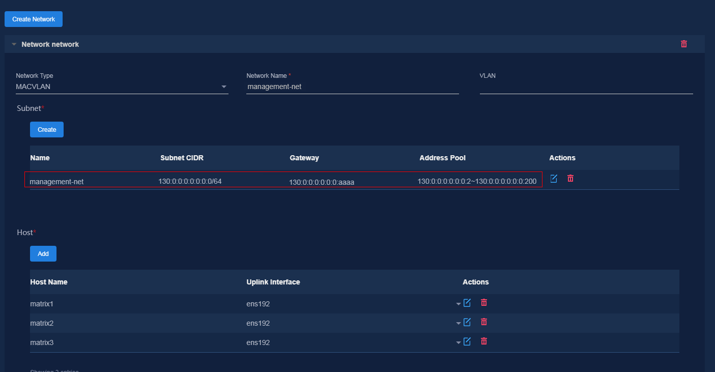
|
|
NOTE: The VLAN field is left blank by default. To configure VLAN, you need to configure the port that connects the Layer 3 switch to the network adapter as a trunk port. The PVID of this port must differ from the VLAN configured here. (As a best practice, do not configure VLAN here.) |
4. After completing the configuration, click Next. On the Bind to Nodes page, click Next to bind the network and subnet to the corresponding component.
Figure 22 Binding the network
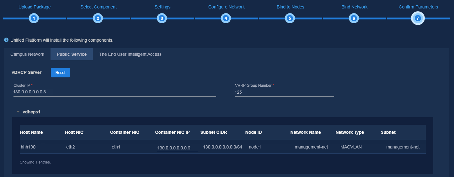
5. On the Bind Network page, bind the network and subnet to the corresponding component, and use a subnet IP address pool to assign IP addresses to the component. After completing the configuration, click Next. When deploying the vDHCP sever, you need to manually enter the VRRP group number with a value range of 1 to 255. The VRRP group number must be unique in the same network. After confirming the parameter settings, click Deploy to start deployment.
Figure 23 Confirming parameters
6. After the deployment is completed, click the
![]() icon on the left of the component name to expand the component
information, or click the Details icon
icon on the left of the component name to expand the component
information, or click the Details icon ![]() to view the
detailed information about the component.
to view the
detailed information about the component.
Figure 24 Viewing component details

Manually configure devices
The following describes the basic configuration procedures for manual configuration when the Spine devices, Leaf devices, and Access devices are not automatically deployed. After Underlay configuration is completed, SeerEngine-Campus can incorporate devices and deploy Overlay configurations.
Configure the Layer 3 switch
1. Enable DHCP and STP globally.
# Enable DHCP.
dhcp enable
#
# Enable STP.
stp global enable
#
2. Configure VLAN-interface 1 and VLAN-interface 4094.
#
interface Vlan-interface1
ipv6 address 132:: 1/64
ipv6 dhcp select relay // DHCP relay related configurations are used for automated device deployment. If Spine/Leaf/Access devices are manually configured for management, the DHCP relay related configurations are not required.
ipv6 dhcp relay server-address 130::106 // IP address of the vDHCP server node
ipv6 dhcp relay server-address 130::107
#
vlan 4094
#
#
interface Vlan-interface4094
ipv6 address 133:: 1/64
#
3. Create VLAN-interface 50 and VLAN-interface 150.
#
vlan 50
vlan 150
#
#
interface Vlan-interface 50
ipv6 address 130::AAAA/64
#
#
interface Vlan-interface 150
ipv6 address 190::AAAA/64
#
4. Configure the interface connecting to the Spine device.
#
interface Ten-GigabitEthernet1/0/49
description to_jieruSpine
port link-type trunk
port trunk permit vlan 1 4094
#
5. Add the interface connecting to Unified Platform to VLAN 150.
#
interface GigabitEthernet1/0/37
port access vlan 150
stp edged-port
#
6. Add the interface connecting to SeerEngine-Campus and vDHCP to VLAN 50.
#
interface GigabitEthernet1/0/30
port access vlan 50
stp edged-port
#
7. Add the default route. Set its next hop to the IP address of the VSI-interface 4094 of the Spine device for interconnection between authenticated users and EIA.
#
ipv6 route-static :: 0 133::2
#
Configure the Spine device
1. Configure the Spine role and sysname.
# For a device whose role is Spine by default, you do not need to configure the Spine role. Otherwise, configure its Spine role first and restart the device for the configuration to take effect.
vcf-fabric role spine
#
sysname spine
#
2. Configure LLDP (to determine the topology).
#
lldp global enable
#
3. Configure STP.
#
undo stp vlan 2 to 4094 enable
stp mode pvst
stp global enable
stp vlan 1 priority 0 // Set the STP priority value of the Spine device.
#
4. Configure SNMP, NETCONF, Telnet, and SSH.
# Configure SNMP. The following provides the default configuration, and the SNMP community strings can be adjusted based on the actual configuration.
snmp-agent
snmp-agent community write private
snmp-agent community read public
snmp-agent sys-info version all
snmp-agent packet max-size 4096
#
# Configure NETCONF.
netconf soap http enable
netconf soap https enable
netconf ssh server enable
restful https enable
#
# Configure Telnet.
telnet server enable
#
# Configure SSH.
ssh server enable
#
5. Configure the username and password of Telnet and SSH.
# Set the username to admin and password to H3C1234567.
local-user admin class manage
local-user admin class manage
password simple H3C1234567 // Make sure the password
meets the complexity requirements. The password must be 10 to 63 characters in
length and contains at least two types of the following characters: digits,
uppercase letters, lowercase letters, and special characters. Chinese
characters are not supported and the password cannot contain the question mark
(?), space, username, or username in reverse order.
service-type telnet http https ssh
authorization-attribute user-role network-admin
authorization-attribute user-role network-operator
#
#
line vty 0 63
authentication-mode scheme
user-role network-admin
user-role network-operator
#
6. Create VLAN 4094 and VLAN-interface 1.
# Create VLAN 4094.
vlan 4094
#
# (Optional) Create VLAN-interface 1.
interface Vlan-interface1
ipv6 address 132:: 4/64
7. Configure OSPF.
#
ospfv3 1
router-id 66.0.0.2
non-stop-routing
area 0.0.0.0
#
8. Configure the loopback interface.
#
interface LoopBack0
ospfv3 1 area 0.0.0.0
ipv6 address 51::3/128 // Configure OSPF.
#
9. Configure the downlink interface of the Spine device. If there are multiple downlink interfaces, create multiple VLAN interfaces.
# Create a VLAN.
vlan 3496
#
# Create a VLAN interface.
interface Vlan-interface3496
ospfv3 1 area 0.0.0.0
ospfv3 network-type p2p
ipv6 address auto link-local
#
# Execute the port trunk permit command on the downlink interface of the Spine device.
#
interface GigabitEthernet1/0/35
port link-mode bridge
port link-type trunk
port trunk permit vlan 1 3496 // It is not required to execute permit vlan 1 for Spine/Leaf/Access devices that are deployed manually.
#
|
|
CAUTION: · The default VLANs automatically delivered by the SeerEngine-Campus: VLAN 100: BFD detection of automated IRF setup. VLANs 101 to 2800: Access switches. VLANs 2801 to 3000: Static access ACs. VLANs 3001 to 3500: Interconnect links for Spine and Leaf devices for automated device deployment. VLANs 3501 to 4000: Security groups. VLANs 4092 to 4094: Reserved. VLANs 1 to 99 and VLANs 4001 to 4091: Not assigned automatically. VLANs 4051 to 4060: Authentication-free VLANs. As a best practice, use VLANs 2 to 99, VLANs 4001 to 4050, and VLANs 4061 to 4091 when configuring VLAN interfaces for routing for VLAN interfaces in route advertisement. At present, the VLAN range can be customized and planned according to specific scenarios. · The multiple links between Spine and Leaf devices are ECMP links. As VLAN 1 is enabled with STP, the link discarding status between spine and leaf nodes is normal. |
10. Enable L2VPN.
#
l2vpn enable
#
11. Configure vpn-target, the IP addresses of VSI VXLAN 4094 and VSI-interface IP address, and L3 VNI for connectivity of the control channel.
# Create vpn-default. Configure the RD and RT manually. Configure the RD and RT as 1:1 in the whole network.
#
ip vpn-instance vpn-default
route-distinguisher 1:1
vpn-target 1:1 import-extcommunity
vpn-target 1:1 export-extcommunity
#
address-family ipv6
vpn-target 1:1 import-extcommunity
vpn-target 1:1 export-extcommunity
#
address-family evpn
vpn-target 1:1 import-extcommunity
vpn-target 1:1 export-extcommunity
#
# Configure the IP address of VSI-interface 4094.
interface Vsi-interface4094
ip binding vpn-instance vpn-default
local-proxy-arp enable
arp proxy-send enable
ipv6 address 133:: 3/64
local-proxy-nd enable // Enable the ARP request proxy sending function to solve the problem that the endpoint device cannot connect to the server if there is no server ARP entry on the device due to network connection timeout.
#
# Configure a VSI-interface and an L3 VNI for Layer 3 forwarding.
# The ip address unnumbered command is used to configure this interface to borrow the IP address of the specified interface. When a security group is created under vpn-default, the source IP of the packets is specified as the interface IP of VSI-interface 4094.
# Create VSI-interface 4092 to configure the L3 VNI of vpn-default.
interface Vsi-interface4092
description SDN_VRF_VSI_Interface_4092
ip binding vpn-instance vpn-default
ip address unnumbered interface Vsi-interface4094
ipv6 address auto link-local
l3-vni 4092
#
# Configure the VSI VXLAN 4094 instance.
vsi vxlan4094
gateway vsi-interface 4094
vxlan 4094
evpn encapsulation vxlan
mac-advertising disable
arp mac-learning disable
nd mac-learning disable
route-distinguisher auto
vpn-target auto export-extcommunity
vpn-target auto import-extcommunity
ipv6 dhcp snooping trust tunnel
loopback-detection action block
loopback-detection enable vlan 4094
#
12. Configure BGP EVPN.
# Configure BGP. If there are multiple leaf nodes, you need to configure multiple peers.
# Configure the BGP AS number to be the same as the AS number set for the fabric in SeerEngine-Campus.
#
bgp 100
non-stop-routing
router-id 66.0.0.2 // The router ID of each device cannot be the same.
peer 51::2 as-number 100 // Configure the BGP peer. The IP address is the IP address of the loopback interface on the Leaf device.
peer 51::2 connect-interface LoopBack0
#
address-family l2vpn evpn
peer 51::2 enable
peer 51::2 reflect-client // Configure a route reflector for forwarding routes between different Leaf devices.
#
ip vpn-instance vpn-default
#
address-family ipv4 unicast
import-route direct // Import directly connected routes. The configuration is required if IPv4 conversational learning is enabled on the leaf device.
import-route static // Import a static route.
#
address-family ipv6 unicast
import-route direct // Import directly connected routes. If conversational learning for IPv6 is enabled on a Leaf device, it is necessary to import directly connected routes.
import-route static // Import a static route.
#
13. Configure the uplink interface (the one connecting to the Layer 3 switch) of the Spine device as the AC interface and bind it to VSI VXLAN 4094.
#
interface Ten-GigabitEthernet1/0/52
port link-mode bridge
port link-type trunk
port trunk permit vlan 1 4094
service-instance 4094 // Create service instance 4094.
encapsulation s-vid 4094 // Match VLAN tag 4094.
xconnect vsi vxlan4094 // Bind VSI VXLAN 4094.
#
14. Configure static routes.
# When the connection between the spine device and Unified Platform is a Layer 3 connection, you need to configure static routes to Unified Platform, the controller, EIA and other service related servers, with the next hop being the IP address of the VLAN-interface 4094 on the L3 switch.
ipv6 route-static vpn-instance vpn-default 130:: 64 133::1 // The destination IP is the network segment of the controller, vDHCP, and EIA.
#
ipv6 route-static vpn-instance vpn-default 190:: 64 133::1 // The destination IP is in the network segment of Unified Platform.
#
Disable MAC address learning and ARP learning on the VXLAN tunnels.
# Disable ARP learning on the VXLAN tunnels to prohibit ARP learning and MAC address learning for remote packets.
vxlan tunnel arp-learning disable
#
# Disable MAC address learning of the VXLAN tunnel.
vxlan tunnel mac-learning disable
#
Configure NTP.
#
clock timezone beijing add 08:00:00
#
# The IP address is the IP address of the NTP server.
ntp-service enable
ntp-service unicast-server 190::195 vpn-instance vpn-default
#
|
|
CAUTION: If Unified Platform is configured with a built-in NTP server in the deployment, as a best practice, configure the NTP server IP as the cluster northbound service IP of Unified Platform. If it is an external NTP server, make sure the NTP server can intercommunicate with the controller and Unified Platform. |
15. Set the bridge MAC address in an unchanged state for an IRF fabric composed of the Spine device.
If the Spine device is an IRF fabric, use the following command to ensure that the bridge MAC address of the device remains unchanged during a master/subordinate switchover.
#
irf mac-address persistent always
#
Configure the Leaf device
|
|
IMPORTANT: If an S5560X switch or S6520X switch is used as a leaf device, set the switch mode to the VXLAN mode and restart the device for the configuration to take effect. |
Before incorporating a Leaf device to SeerEngine-Campus, manually perform the following operations:
# View the switch mode and make sure it is VXLAN mode.
dis switch-mode status
Switch-mode in use: VXLAN MODE.
Switch-mode for next reboot: VXLAN MODE.
#
# View the switch-mode command.
[Leaf11]switch-mode ?
0 NORMAL MODE(default)
1 VXLAN MODE
2 802.1BR MODE
3 MPLS MODE
4 MPLS-IRF MODE
#
# Set the mode to VXLAN mode, and then restart the device for the configuration to take effect.
switch-mode 1
#
To configure a Leaf device:
1. Configure the Leaf role and sysname.
# For a device whose role is Leaf by default, you do not need to configure the Leaf role. Otherwise, configure its Leaf role first and restart the device for the configuration to take effect.
#vcf-fabric role leaf
#
# Configure the sysname.
sysname leaf1
#
2. Configure LLDP (to determine the topology).
#
lldp global enable
#
Configure STP.
#
undo stp vlan 2 to 4094 enable
stp mode pvst
stp global enable
stp vlan 1 priority 4096
#
Enable stp tc-restriction on the Leaf downlink interface.
int GigabitEthernet1/0/13
#
stp tc-restriction #
|
|
IMPORTANT: Use the stp tc-restriction command to enable TC-BPDU transmission restriction on the downlink interface of the Leaf device. If it is directly connected to the endpoint, execute the stp edged-port command. |
3. Configure SNMP, NETCONF, Telnet, and SSH.
# Configure SNMP. The following is the default configuration. The SNMP community is configured as required.
snmp-agent
snmp-agent community write private
snmp-agent community read public
snmp-agent sys-info version all
snmp-agent packet max-size 4096
#
# Configure NETCONF.
#
netconf soap http enable
netconf soap https enable
netconf ssh server enable
restful https enable
#
# Configure Telnet.
telnet server enable
#
# Configure SSH.
ssh server enable
#
4. Configure the username and password of Telnet and SSH.
# Set the username to admin and password to H3C1234567.
local-user admin class manage
local-user admin class manage
password simple H3C1234567 // Make sure the password meets the complexity requirements. The password must be 10 to 63 characters in length and contains at least two types of the following characters: digits, uppercase letters, lowercase letters, and special characters. Chinese characters are not supported and the password cannot contain the question mark (?), space, username, or username in reverse order.
service-type telnet http https ssh
authorization-attribute user-role network-admin
authorization-attribute user-role network-operator
#
#
line vty 0 63
authentication-mode scheme
user-role network-admin
user-role network-operator
#
5. Create VLAN 4094 and VLAN-interface 1.
# Create VLAN 4094.
vlan 4094
#
# Create VLAN-interface 1.
interface Vlan-interface1
ipv6 address 132:: 5/64
#
6. Configure OSPF.
#
ospfv3 1
router-id 66.0.0.3
non-stop-routing
area 0.0.0.0
#
7. Configure the loopback interface.
#
interface LoopBack0
ipv6 address 51::2/128 // Establish a BGP peer with the Spine device.
ospfv3 1 area 0.0.0.0
#
8. Configure an L3 VLAN interface for interconnection with the Spine device.
# Create a VLAN.
vlan 3496 // It must be the same as the VLAN on the Spine device. For details, see "Configuring the IPv6 service for managed devices."
#
# Create a VLAN interface.
interface Vlan-interface3496
ospfv3 1 area 0.0.0.0
ospfv3 network-type p2p
ipv6 address auto link-local
#
# Configure port trunk permit vlan on the Leaf uplink interface.
#
interface GigabitEthernet5/0/19
port link-mode bridge
port link-type trunk
port trunk permit vlan 1 3496
#
|
|
CAUTION: · The default VLANs automatically delivered by the SeerEngine-Campus: VLAN 100: BFD detection of automated IRF setup. VLANs 101 to 2800: Access switches. VLANs 2801 to 3000: Static access ACs. VLANs 3001 to 3500: Interconnect links for Spine and Leaf devices for automated device deployment. VLANs 3501 to 4000: Security groups. VLANs 4092 to 4094: Reserved. VLANs 1 to 99 and VLANs 4001 to 4091: Not assigned automatically. VLANs 4051 to 4060: Authentication-free VLANs. As a best practice, use VLANs 2 to 99, VLANs 4001 to 4050, and VLANs 4061 to 4091 when configuring VLAN interfaces for routing for VLAN interfaces in route advertisement. At present, the VLAN range can be customized and planned according to specific scenarios. · The multiple links between Spine and Leaf devices are ECMP links. As VLAN 1 is enabled with STP, the link discarding status between spine and leaf nodes is normal. |
9. Enable L2VPN.
# Enable l2vpn.
l2vpn enable
#
10. Configure vpn-default, VSI VXLAN 4094 and VSI-interface IP, and L3 VNI, and configure the service instance (binding VXLAN 4094) on the downlink AC interface (the one connecting to the Access device), for connectivity of the control channel.
# Create vpn-default. Configure the RD and RT manually. Configure the RD and RT as 1:1 in the whole network.
#
ip vpn-instance vpn-default
route-distinguisher 1:1
vpn-target 1:1 import-extcommunity
vpn-target 1:1 export-extcommunity
#
address-family ipv6
vpn-target 1:1 import-extcommunity
vpn-target 1:1 export-extcommunity
#
address-family evpn
vpn-target 1:1 import-extcommunity
vpn-target 1:1 export-extcommunity
#
# Configure the IP address of VSI-interface 4094.
#
interface Vsi-interface4094
ip binding vpn-instance vpn-default
local-proxy-arp enable
arp proxy-send enable // This new command enables the controller to connect to the Access device when the ARP is absent on the Leaf devices. In this case, VSI-interface 4094 of the Leaf device must be configured.
ipv6 address 133:: 6/64
local-proxy-nd enable
#
# Configure a VSI-interface and an L3 VNI for Layer 3 forwarding.
# The ip address unnumbered command is used to configure this interface to borrow the IP address of the specified interface. When a security group is created under vpn-default, the source IP of the packets is specified as the interface IP of VSI-interface 4094.
#
interface Vsi-interface4092
ip binding vpn-instance vpn-default
ip address unnumbered interface Vsi-interface4094
ipv6 address auto link-local
l3-vni 4092#
# Configure the VSI VXLAN 4094 instance.
#
vsi vxlan4094
gateway vsi-interface 4094
vxlan 4094
evpn encapsulation vxlan
mac-advertising disable
arp mac-learning disable
nd mac-learning disable
route-distinguisher auto
vpn-target auto export-extcommunity
vpn-target auto import-extcommunity
dhcp snooping trust tunnel
ipv6 dhcp snooping trust tunnel
loopback-detection action block
loopback-detection enable vlan 4094
#
# Configure the downlink interface of the Leaf device connecting to the Access device as an AC interface.
interface GigabitEthernet1/0/13
port link-type trunk
port trunk permit vlan 1 to 99 101 to 4094
link-aggregation mode dynamic
stp tc-restriction
mac-based ac
#
service-instance 4094
encapsulation s-vid 4094
#
11. Configure BGP EVPN.
# Configure BGP 100 and specify a Spine device as a BGP peer.
#
bgp 100
non-stop-routing
router-id 66.0.0.3 // The router ID of each device cannot be the same. As a best practice, configure the ID as the IP address of the loopback interface.
peer 51::3 as-number 100
peer 51::3 connect-interface LoopBack0
#
address-family l2vpn evpn
peer 51::3 enable
#
ip vpn-instance vpn-default
#
address-family ipv6 unicast
#
12. Configure static routes.
# When the connection between the spine device and Unified Platform is a Layer 3 connection, you need to configure static routes to Unified Platform, the controller, EIA and other service related servers, with the next hop being the IP address of the VLAN-interface 4094 on the L3 switch.
ipv6 route-static vpn-instance vpn-default 130:: 64 133::1 // The destination IP is the network segment of the controller.
#
ipv6 route-static vpn-instance vpn-default 190:: 64 133::1 // The destination IP is the network segment of Unified Platform.
#
Configure DHCP snooping.
#
ipv6 dhcp snooping enable vlan 2 to 4094
#
13. Configure the IP source guard as filter-free for VLAN 1 and VLAN 4094.
# The configuration is required when IP source guard is configured for the leaf downlink interface. The service is not affected when IP source guard is not configured.
ip verify source exclude vlan 1
ip verify source exclude vlan 4094
#
14. Disable MAC address learning and ARP learning on the VXLAN tunnels.
# Disable ARP address learning on the VXLAN tunnels.
vxlan tunnel arp-learning disable
#
# Disable MAC address learning on the VXLAN tunnels.
vxlan tunnel mac-learning disable
#
15. Enable conversational learning. (This function is optional and disabled by default. You can enable it as required.)
If conversational learning is enabled on the Leaf device, the direct routes need to be imported under vpn-default on the spine device to import all private subnet routes of the endpoints to leaf and spine devices to ensure interoperability between the endpoints and the server and the external networks.
# To save hardware resources, the remote ARP entries synchronized through EVPN are not delivered to hardware by default and only delivered in the case of a traffic request.
ip forwarding-conversational-learning // Enable conversational learning.
# After the traffic is stopped, the default aging time for deleting table entries on hardware is 60 minutes. You can use the following command to set the aging time.
[leaf1]ip forwarding-conversational-learning aging ?
INTEGER<60-1440> Aging time in (minutes)
#
|
|
IMPORTANT: · It is recommended that S5560X-HI and S6520X-HI devices should be enabled with conversational learning. · It is not recommended to configure conversational learning when the leaf device works as a border device at the same time. |
16. Configure NTP.
#
clock timezone beijing add 08:00:00
#
# The IP address is the IP address of the NTP server.
ntp-service enable
ntp-service unicast-server 190::195 vpn-instance vpn-default
#
|
|
IMPORTANT: If Unified Platform is configured with a built-in NTP server in the deployment, as a best practice, configure the NTP server IP as the cluster northbound service IP of Unified Platform. If it is an external NTP server, make sure the NTP server can intercommunicate with the controller and Unified Platform. |
17. Verify the configuration.
After finishing the above configuration tasks, check whether those tasks are successfully configured. The following information can be viewed from both the Spine and Leaf devices:
[leaf1] display interface Vsi-interface brief
Brief information on interfaces in route mode:
Link: ADM - administratively down; Stby - standby
Protocol: (s) - spoofing
Interface Link Protocol Primary IP Description
Vsi4092 UP UP -- SDN_VRF_VSI_Interface_4092// VSI-interface 4092 is successfully created.
Vsi4094 UP UP --
[leaf1]
[leaf1]dis l2vpn vsi
Total number of VSIs: 2, 1 up, 1 down, 0 admin down
VSI Name VSI Index MTU State
Auto_L3VNI4092_4092 0 1500 Down // Automatically generated.
vxlan4094 1 1500 Up
[leaf1]
[leaf1] display interface Tunnel brief
Brief information on interfaces in route mode:
Link: ADM - administratively down; Stby - standby
Protocol: (s) - spoofing
Interface Link Protocol Primary IP Description
Tun1 UP UP -- // Tunnel in UP state.
[leaf1]
[leaf1] display interface Tunnel
Tunnel1
Current state: UP
Line protocol state: UP
Description: Tunnel1 Interface
Bandwidth: 64 kbps
Maximum transmission unit: 4038
Internet protocol processing: Disabled
Last clearing of counters: Never
Tunnel source 51::2, destination 51::3
Tunnel protocol/transport UDP_VXLAN/IPv6
Last 300 seconds input rate: 521 bytes/sec, 4168 bits/sec, 3 packets/sec
Last 300 seconds output rate: 1021 bytes/sec, 8168 bits/sec, 4 packets/sec
Input: 18304 packets, 2831888 bytes, 0 drops
Output: 21089 packets, 5695406 bytes, 0 drops
[leaf1]
[leaf1] ping ipv6 -vpn-instance vpn-default 130::AAAA // Gateway of the controller and DHCP server.
Ping6(56 data bytes) 133::6 --> 130::AAAA, press CTRL+C to break
56 bytes from 130::AAAA, icmp_seq=0 hlim=63 time=3.276 ms
56 bytes from 130::AAAA, icmp_seq=1 hlim=63 time=2.374 ms
56 bytes from 130::AAAA, icmp_seq=2 hlim=63 time=2.327 ms
56 bytes from 130::AAAA, icmp_seq=3 hlim=63 time=2.455 ms
56 bytes from 130::AAAA, icmp_seq=4 hlim=63 time=2.296 ms
--- Ping6 statistics for 130::AAAA in VPN instance vpn-default ---
5 packet(s) transmitted, 5 packet(s) received, 0.0% packet loss
round-trip min/avg/max/std-dev = 2.296/2.546/3.276/0.369 ms
[leaf~133::6]%Mar 5 07:23:21:372 2021 leaf~133::6 PING/6/PING_VPN_STATISTICS: Ping6 statistics for 130::AAAA in VPN instance vpn-default: 5 packet(s) transmitted, 5 packet(s) received, 0.0% packet loss, round-trip min/avg/max/std-dev = 2.296/2.546/3.276/0.369 ms.
[leaf1]
18. Set the bridge MAC address in an unchanged state for an IRF fabric composed of the Leaf device.
If the Spine device is an IRF fabric, use the following command to ensure that the bridge MAC address of the device remains unchanged during a master/subordinate switchover.
#
irf mac-address persistent always
#
Configure the Access device
1. Configure the Access role and sysname of the device.
# For a device whose role is Access by default, you do not need to configure the Access role. Otherwise, configure its Access role first and restart the device for the configuration to take effect.
#
vcf-fabric role access
#
#
sysname access1
#
2. Configure LLDP (to determine the topology).
#
lldp global enable
#
3. Configure STP.
#
stp global enable
#
4. Configure SNMP, NETCONF, Telnet, and SSH.
# Configure SNMP. The following is the default configuration. The SNMP community is configured as required.
#
snmp-agent
snmp-agent community write private
snmp-agent community read public
snmp-agent sys-info version all
snmp-agent packet max-size 4096
#
# Configure NETCONF.
netconf soap http enable
netconf soap https enable
netconf ssh server enable
restful https enable
#
# Configure Telnet.
telnet server enable
#
# Configure SSH.
ssh server enable
#
5. Configure the username and password of Telnet and SSH.
# Set the username to admin and password to H3C1234567.
local-user admin class manage
local-user admin class manage
password simple H3C1234567 // Make
sure the password meets the complexity requirements. The password must be 10 to
63 characters in length and contains at least two types of the following
characters: digits, uppercase letters, lowercase letters, and special
characters. Chinese characters are not supported and the password cannot
contain the question mark (?), space, username, or username in reverse order.
service-type telnet http https ssh
authorization-attribute user-role network-admin
authorization-attribute user-role network-operator
#
#
line vty 0 63
authentication-mode scheme
user-role network-admin
user-role network-operator
#
6. Execute the permit vlan all command on the uplink interface that connects the Access device to the Leaf device.
# Execute the permit vlan all command on the uplink interface of the Access device.
interface Ten-GigabitEthernet1/0/52
port link-mode bridge
port link-type trunk
port trunk permit vlan all
#
7. # Create a VLAN.
#
vlan 4093 to 4094
#
8. (Optional) Configure the L3 interface of VLAN 1.
#
interface Vlan-interface1
ipv6 address 132:: 2/64
#
9. Configure the L3 interface of VLAN 4094, through which SeerEngine-Campus can manage Access devices.
#
interface Vlan-interface4094
ipv6 address 133:: 5/64
#
10. Configure the static IP address of VLAN 4094.
# When the connection between the spine device and Unified Platform is a Layer 3 connection, you need to configure static routes to Unified Platform, the controller, EIA and other service related servers, with the next hop being the IP address of the VLAN-interface 4094 on the L3 switch.
ipv6 route-static 130:: 64 133::1 // The destination IP address resides in the network segment of the controller.
ipv6 route-static 190:: 64 133::1 // The destination IP address resides in the network segment of Unified Platform.
11. Configure the NTP server.
#
clock timezone beijing add 08:00:00
#
# The IP address is the IP address of the NTP server.
ntp-service enable
ntp-service unicast-server 190::195
#
|
|
IMPORTANT: If Unified Platform is configured with a built-in NTP server in the deployment, as a best practice, configure the NTP server IP as the cluster northbound service IP of Unified Platform. If it is an external NTP server, make sure the NTP server can intercommunicate with the controller and Unified Platform. |
12. Configure the STP edge port.
After the Access device is incorporated by the SeerEngine-Campus controller, the controller automatically sets the ports used by the Access device to connect to users as STP edge ports and automatically assigns a VLAN ID to each port. If the controller fails to automatically deploy the edge port, you can configure it manually.
#
interface GigabitEthernet1/0/22
port access vlan 115
stp edged-port
#
13. Set the bridge MAC address in an unchanged state for an IRF fabric composed of the Access device.
If the Access device is an IRF fabric, use the following command to ensure that the bridge MAC address of the device remains unchanged during a master/subordinate switchover.
#
irf mac-address persistent always
#
Manually incorporate a device
After manually deploying Underlay configurations of the device, perform the following tasks to configure the fabric and DHCP server:
1. Configure a fabric.
a. Access Automation > Campus Network > Fabrics page, and click Add.
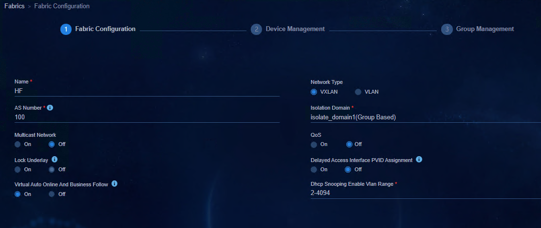
b. Configure a fabric on the Fabric Configuration page. Parameters are described as follows:
- Name: Enter the name with no limitation.
- AS Number: The value is an integer in the range of 1 to 4294967295. When a device is manually deployed and managed, make sure the AS number set in the fabric is the same as the BGP AS number manually configured on the device.
- Isolation Domain: Select the isolation domain of the fabric (isolate_domain1 by default). The isolation domain policy mode can specify the policy mode as IP-based or group-based.
- Networking Model: Select as required.
- Multicast Network: Not supported for the IPv6 service and Off is selected here.
- Lock Underlay: It is Off by default. You can select On if necessary.
- Delayed Access Interface PVID Assignment: It is Off by default and the controller will automatically assign PVID when the device is activated. If you select On, the controller will not assign PVID when the device is activated, and you can manually configure the PVID after the device is activated.
- Virtual Auto Online And Business Follow: It is On by default. It is used to control the authorization of the VXLAN network and the authorization of access policies between security groups.
- QoS: Not supported for the IPv6 service and Off is selected here.
Figure 25 Configuring a fabric
a. Click OK. The added fabric is displayed on the Fabrics page.
2. Incorporate a device.
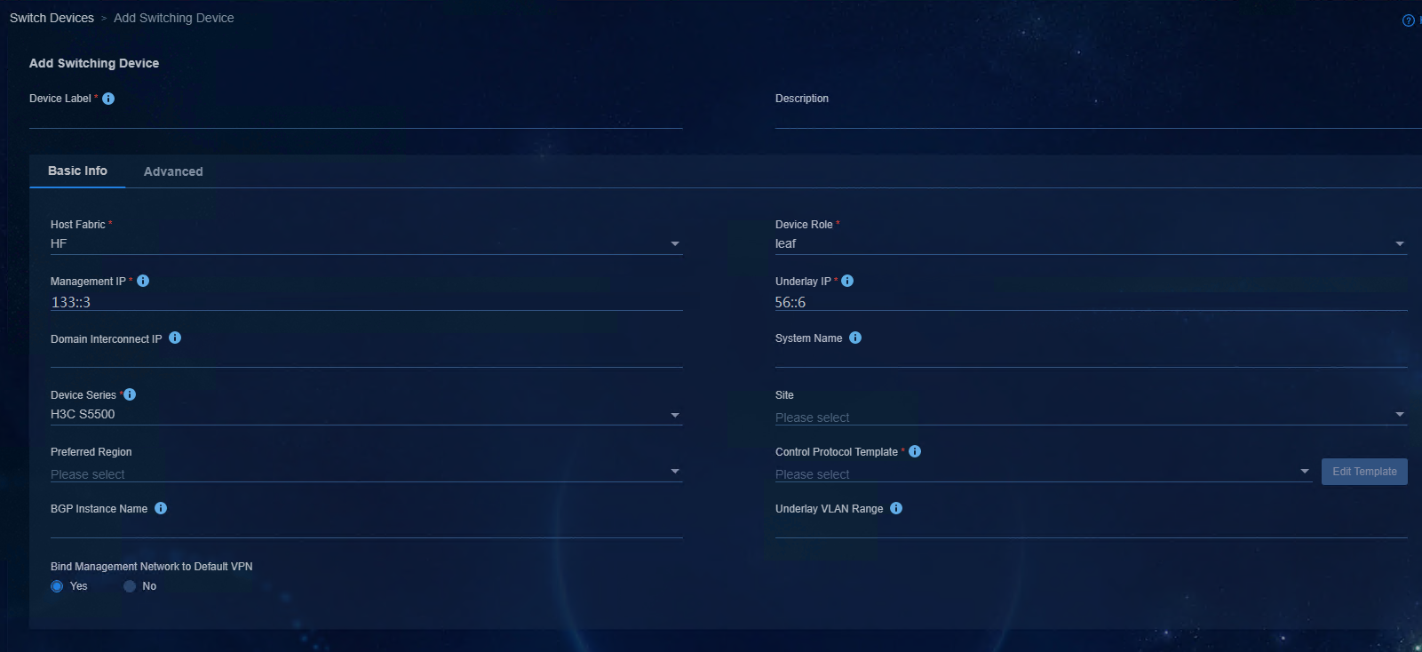
Access Automation > Campus Network > Device Group > Add Device page, and specify the parameters.
¡ In the Basic Info area:
- Fabric: Select a fabric.
- Device Role: There are three roles for option, namely, Spine, Leaf, and Access. Select the role according to the actual role of the device in the topology, and make sure the selected role is the same as that configured on the device.
- Management IP: Enter the IP address of VXLAN-interface 4094/VLAN-interface 4094.
- Underlay IP: Enter the IP address of the loopback interface of the device.
- Device Series: Select the product series corresponding to the device model.
- Other parameters: Retain the default settings.
Figure 26 Incorporating a device
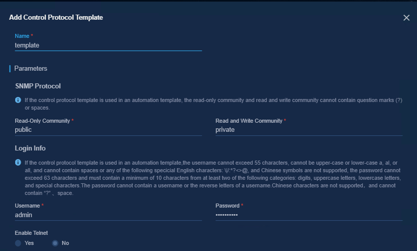
¡ In the Add Control Protocol Template area:
- Name: Enter the template name.
- Read and White Community: According to the SNMP parameters set in the above device settings, enter private here.
- Read-Only Community: According to the SNMP parameters set in the above device settings, enter public here.
- Username: According to the username of local-user set in the above device settings, the username here is admin.
- Password: Enter the password of the local-user set in the above device settings. The password must be 10 to 63 characters in length and contains at least two types of the following characters: digits, uppercase letters, lowercase letters, and special characters. Chinese characters are not supported and the password cannot contain the question mark (?), space, username, or username in reverse order.
Figure 27 Adding a control protocol template
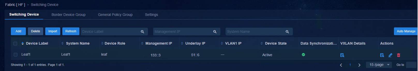
3. After the device is added, the initial Device State is Inactive because a period of time is needed for data synchronization. After the data is synchronized, click Refresh. If the device state becomes Active, the device is successfully connected.
Figure 28 Activating a device
4. After devices are incorporated, you can use the display openflow instance 1 controller command to view detailed information about the devices connected to the SeerEngine-Campus controller for Spine and Leaf devices.
[Leaf1]display openflow instance 1 controller
Instance 1 controller information:
Reconnect interval: 60 (s)
Echo interval : 5 (s)
Controller ID : 1
Controller IPv6 address : 130::191
Controller port : 6633
Local IPv6 address : 133::3
Controller role : Master
Connect type : TCP
Connect state : Established
Packets sent : 44
Packets received : 163
SSL policy : --
Control SSL policy : --
VRF name : vpn-default
Controller ID : 2
Controller IPv6 address : 130::192
Controller port : 6633
Local IPv6 address : 133::3
Controller role : Slave
Connect type : TCP
Connect state : Established
Packets sent : 42
Packets received : 161
SSL policy : --
Control SSL policy : --
VRF name : vpn-default
5. Configure the DHCPv6 server.
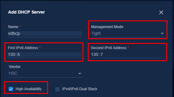
a. Access Automation > Campus Network > Network Parameters > DHCP page and click Add. Configure the vDHCP server on the pop-up page as shown in the following figure.
- Name: Enter the name.
- Management Mode: Select Tight because vDHCP only supports this mode.
- High Available: It is necessary to select it for a cluster environment and unnecessary for a single-node environment.
- First IPv6 Address and Second IPv6
Address: Enter the IPv6 addresses assigned during vDHCP deployment. It can
be viewed on the vDHCP deployment page. Access System > Deployment
Management, expand Public Service page, and click the ![]() icon
to view the details.
icon
to view the details.
- Vendor: Select H3C.
- Select High Availability.
Figure 29 Adding the DHCP server
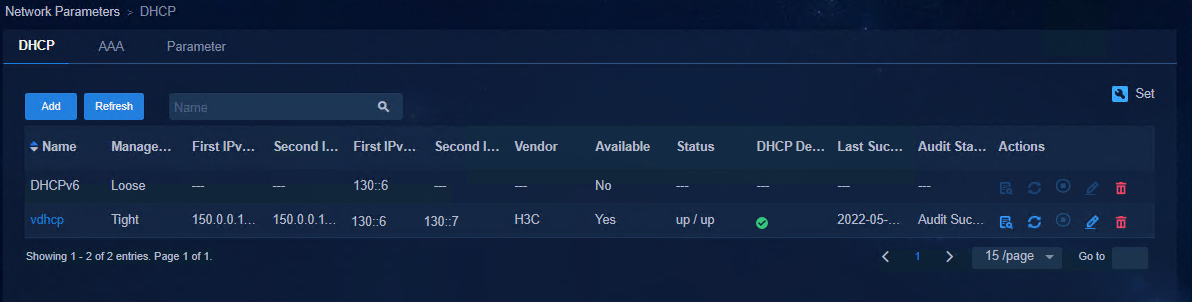
a. After completing the configuration, click OK. The newly added DHCP server is displayed in the DHCP list.
Figure 30 Viewing the DHCP server
Automated device deployment
For details, see Configure automated deployment of pure IPv6 devices.
Configure automated deployment of pure IPv6 devices
There is no difference between the IPv6 service and IPv4 service in terms of the networking architecture, precautions for configuration, and supported device models. For details, see AD-Campus 6.2 Automated Configuration Guide.
Configuration workflow
Figure 31 Underlay automated deployment flowchart
The preceding figure shows the Underlay automated deployment flowchart. First, perform initial configurations such as automation parameter configuration on the controller page. Then, restart the device with no configuration and obtain the corresponding automation template for the specific role and deploy it to the related device. After the primary RR MAC address is specified on the controller, BGP configuration is deployed automatically, and a VXLAN Tunnel is created between the Spine device and the Leaf device. When devices are incorporated by the controller automatically and added to the corresponding device group and interface group, the Underlay automated deployment is complete.
Configure the Layer 3/2 architecture
Configure the Layer 3 switch
1. Configure VLAN 1 and VLAN 4094 for communication with devices.
#
vlan 1
#
vlan 4094
#
interface Vlan-interface1
ipv6 dhcp select relay
ipv6 dhcp relay server-address 130::6 // IP address of the master vDHCP
ipv6 dhcp relay server-address 130::7 // IP address of the backup vDHCP
ipv6 address 132:: 1/64
undo ipv6 nd ra halt #
#
interface Vlan-interface4094 // The device management IP address is assigned by the controller, and DHCP relay is not required here.
ipv6 address 133:: 1/64
undo ipv6 nd ra halt
#
2. Configure VLAN 50 for SeerEngine-Campus and DHCP management.
#
vlan 50
#
interface Vlan-interface50
ipv6 address 130::AAAA/64
#
3. Configure VLAN 150 for communication between the controller/Unified Platform and PCs.
#
interface Vlan-interface150
ipv6 address 190::AAAA/64
#
4. Configure the interface connecting to the Spine device.
#
interface Ten-GigabitEthernet1/0/6
description to_spine
port link-type trunk
port trunk permit vlan all
ipv6 dhcp snooping trust
#
5. Configure the interface of the external device (Layer 3 switch) connecting to the server.
#
interface GigabitEthernet1/0/7 // Connect to the network adapters of SeerEngine-Campus and vDHCP.
port access vlan 50
#
interface GigabitEthernet1/0/37 // Connect to the network adapters of Unified Platform, SeerEngine-Campus, and vDHCP.
description eth1-ipv6
port access vlan 150
#
Configure the controller
Configure basic settings
1. Log in to SeerEngine-Campus. Access Automation > Campus Network > Network Parameters > Parameter > Global Settings page, and set IPv6 to Yes (default).
Figure 32 Enabling IPv6
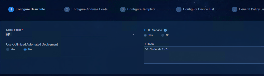
2. Access Guide > Campus Wizard > Device Online Planning > Configure Basic Info page, click the Select Fabric drop-down menu, and select Add Fabric. Specify the following parameters and click OK.
Figure 33 Configuring a fabric
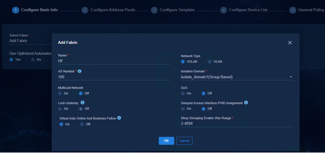
¡ Name: a maximum string of 255 characters (case-sensitive).
¡ Network Type: VXLAN by default.
¡ AS Number: The value is an integer in the range of 1 to 4294967295. For multi-fabric networking, each fabric must have a unique AS number. During automated deployment, the SeerEngine-Campus controller delivers the BGP AS number to the device added to the fabric based on the AS number set in the fabric.
¡ Isolation Domain: Select the isolation domain of the fabric (isolate_domain1 by default). The isolation domain policy mode can specify the policy mode as IP-based or group-based.
¡ Multicast Network: Not supported for the IPv6 service and Off is selected here.
¡ Lock Underlay: It is Off by default. Disable it during automated device deployment, and enable it as required after automated device deployment is completed.
¡ QoS: Not supported for the IPv6 service and Off is selected here.
¡ Delayed Access Interface PVID Assignment: It is Off by default and the controller will automatically assign PVID when the device is activated. If you select On, the controller will not assign PVID when the device is activated, and you can manually configure the PVID after the device is activated.
¡ Virtual Auto Online And Business Follow: It is used to control the authorization of VXLAN network and is On by default.
Figure 34 Configuring the TFTP service
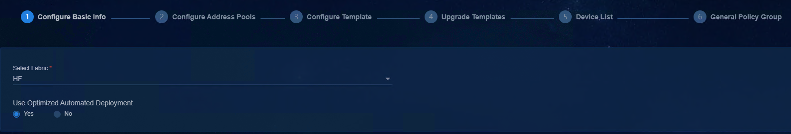
3. The Use Optimized Automated Deployment parameter is set to No by default since the optimized automated deployment is not supported for the IPv6 service.
4. Enter the bridge MAC address of the Spine device in the RR MAC field. You do not need to enter the RR MAC address if the fabric uses the Single-Leaf architecture. Click Next.
Figure 35 Configuring the RR MAC address
|
|
NOTE: If the Spine device is an IRF fabric, enter the bridge MAC addresses of the main processing units of all member devices in the RR MAC field, separated by commas (,). |
5. To view the bridge MAC address of the Spine device, access the device CLI and use either of the following methods:
¡ Method 1: Execute the display device manuinfo command.
[leaf~133::4]dis device manuinfo slot 1
Slot 1 CPU 0:
DEVICE_NAME : S5560X-54C-EI
DEVICE_SERIAL_NUMBER : 210235A1XCM195A000QK
MAC_ADDRESS : 4CE9-E498-16CB
MANUFACTURING_DATE : 2019-05-20
VENDOR_NAME : H3C
Fan 1:
DEVICE_SERIAL_NUMBER : NONE
Fan 2:
DEVICE_SERIAL_NUMBER : NONE
Power 1:
DEVICE_NAME : LSPM2150A
DEVICE_SERIAL_NUMBER : 210231A1U0H195001022
MANUFACTURING_DATE : 2019-05-07
VENDOR_NAME : H3C
¡ Method 2: Execute the debug stack show memberinfo command in probe view.
[leaf~133::4-probe]debug stack show memberinfo slot 1
=============================================================
Member Information of STACK Module
=============================================================
MemID:1, LocalSlotID:1, Priority:1, Mode:90
MaxMemNum:10, MaxPortMemberPort:4, StackCapability:5
BridgeMac:4c:e9:e4:98:16:cb CpuMac:f0:10:90:db:74:02 DeviceInfo:S5560X-EI
Get the Wrong Packet Number :0.
Configure address pools
1. To configure an address pool, bind the DHCP server first. Click the drop-down arrow of DHCP Server, and select Add DHCP Server. On the pop-up page, specify the related parameters of H3C vDHCP.
Figure 36 Adding the DHCP server
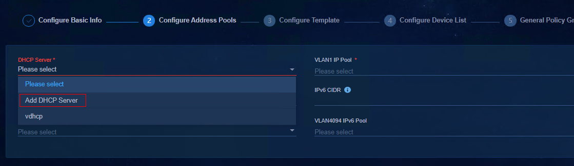
Figure 37 DHCP

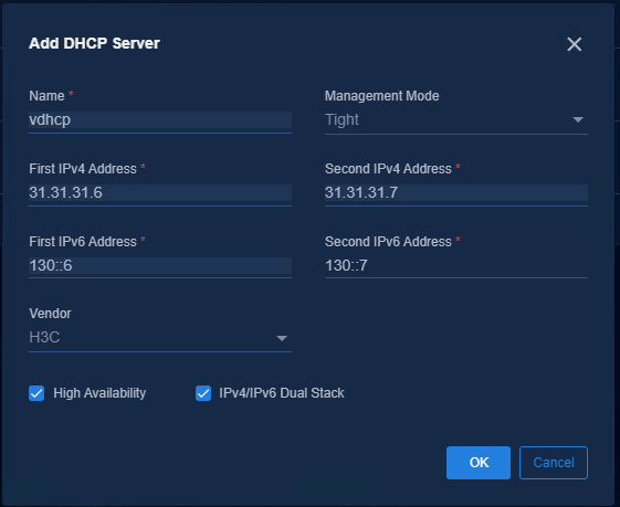
¡ Name: Enter the name.
¡ Management Mode: Select Tight because vDHCP only supports this mode.
¡ High Available: It is necessary to select it for a cluster environment and unnecessary for a single-node environment.
¡ First
IPv6 Address and Second IPv6 Address: Enter
the IPv6 addresses assigned during vDHCP deployment. It can be viewed on the
vDHCP deployment page. Access System > Deployment Management,
expand Public Service page, and click the ![]() icon to view the
details.
icon to view the
details.
¡ Vendor: Select H3C.
¡ For vDHCP, dual-stack can be enabled, but it cannot be disabled once it is enabled. The user terminal can obtain the IPv4 address when the user comes online.
Figure 38 Adding the DHCP server
|
|
NOTE: · The IP address is the IP address assigned for public network deployment. To view the IP address of vDHCP, access System > Deployment Management > Public Service, and click Details. · The DHCP server for automated device deployment must be an H3C vDHCP server. |
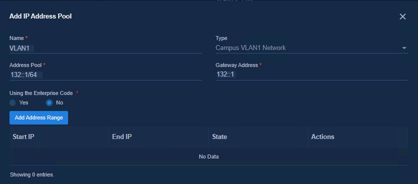
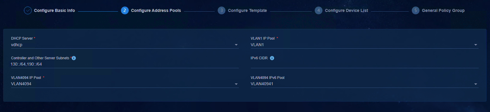
2. Add the IPv6 address pool for VLAN 1. In the Address Pool field, enter the network segment of VLAN 1 (132::/64) set on the Layer 3 switch. In the Gateway Address field, enter the IP address of VLAN 1 set on the Layer 3 switch.
Figure 39 VLAN 1
3. Add an address pool for VLAN 4094. In the Address Pool field, enter the network segment of VLAN 4094 (133::/64) set on the Layer 3 switch. In the Gateway Address field, enter the IP address of VLAN 4094 set on the Layer 3 switch.
Figure 40 Adding an address pool for VLAN 4096

4. Controller and Other Server Subnets: During automated device deployment, the SeerEngine-Campus controller delivers the static routes of the configured IP address segment to the device. You need to add the management network segment of the controller, the IP address segment 130::/64 of the controller, and the network segment 190::/64 where the EIA is located. Multiple network segments can be added and separated by commas (.).
|
|
NOTE: Multiple network segments need to be added if Unified Platform, the controller, and EIA reside in different network segments. |
Figure 41 Configuring the IPv6 management network segment of the server
|
|
NOTE: The configurations of VLAN 4094 IPv4 address pool and IPv4 network segment are not necessary for automated deployment of pure IPv6 Underlay without the IPv4 service. To use IPv4 addresses, you need to add an IPv4 DHCP server. This document does not describe the configuration related to the IPv4 service. For related information, see AD-Campus 6.2 Automated Deployment Guide. |
Configure device role templates
Configuring a device role template is to configure an automation template.
· Local Username and Local Password: If the username on the Configure Template page is the same as that configured for the NETCONF protocol in Control Protocol Template, the passwords of the two must be the same. The local username and password of the two templates can differ from each other. The username and password configured for the NETCONF protocol in Control Protocol Template are used for the controller to access devices. The local username and password here are used for the Spine device to access the Leaf device. You can click Edit Template to enter the page for editing the control protocol template.
· NTP Server: If a built-in NTP server is configured when Unified Platform is deployed, as a best practice, configure the IP address of the NTP server as the cluster northbound service IP address of Unified Platform. You can enter the IP address of the NTP time server in the customer network to ensure network connectivity.
· Support for Version Upgrade: No by default.
· Master Spine MAC: Specify the bridge MAC address of the master Spine device to assign the Underlay IP address and Underlay VLAN. (If the Spine device is an IRF fabric, the Spine device corresponding to the bridge MAC specified in this template is the master device.)
· Auto-Allocate Underlay IP: Yes (default).
¡ Yes: The Spine device automatically assigns IP addresses to the loopback interface 0 of the Spine and Leaf devices according to the address segment of the Underlay IP Range set in the template.
¡ No: You need to manually assign IP addresses to the loopback interface 0 of the Spine and Leaf devices. If you set this to No, set Enable Whitelist to Yes for the Leaf template and Spine template, and must specify the Underlay IP address in the device list.
· Underlay IP Protocol Stack: Select IPv6.
· Router ID Pool: It is used by BGP and OSPFv3 to assign the router ID, which is used to identify the serial number of a router.
· Underlay IP Range: Specify the IP address range. It is used to assign IP addresses to loopback interface 0.
· Underlay VLAN Range: Specify the available VLAN range to establish Underlay OSPF neighbors. As a best practice, use the default settings.
· Uplink Interface: The full name of the uplink interface of the Spine device (that is, the interface directly connecting to the Layer 3 switch) needs to be specified. During automated device deployment, the controller allocates the AC configuration information of VLAN 4094 - VXLAN 4094 to this interface. The interface is used for service interaction between devices and the controller.
· Enable Whitelist:
¡ When it is No:
- If the serial number of the specified device is in the device list, the automated deployment of the device is carried out based on the information specified in the device list, and the device is incorporated by the controller with the specified device label.
- If the serial number of the specified device is not in the device list, the automated deployment of the device is carried out by using the default role, and the default label is "role name + IP address of VLAN 4094".
¡ When it is Yes:
- If the serial number of the specified device is in the device list, the automated deployment of the device is carried out based on the information specified in the device list, and the device is incorporated by the controller with the specified device label.
- If the serial number of the specified device is not in the device list, the automated device deployment fails.
|
|
NOTE: If the Spine device is an IRF fabric, the Master Spine MAC in the Spine Template is the bridge MAC address of the master device. |
Figure 42 Configuring device role template
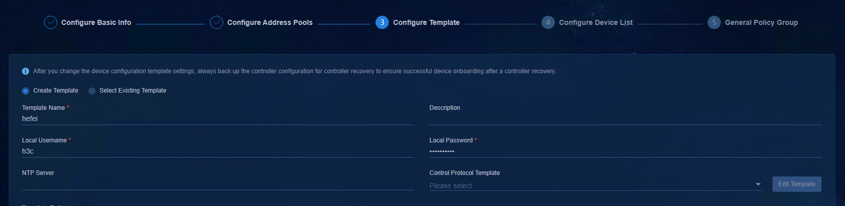
Figure 43 Spine template
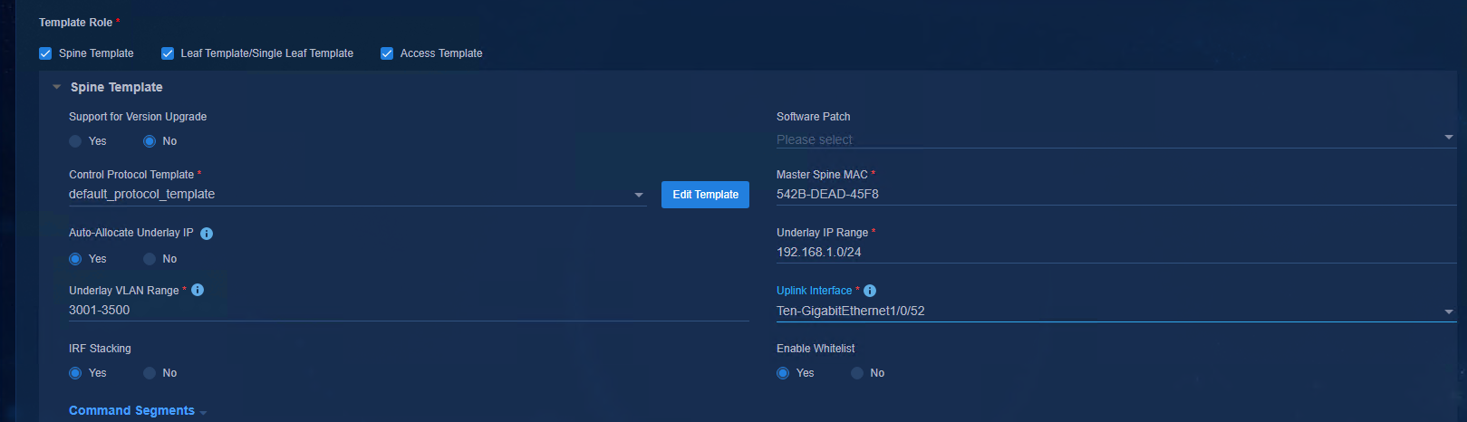
Figure 44 Leaf template
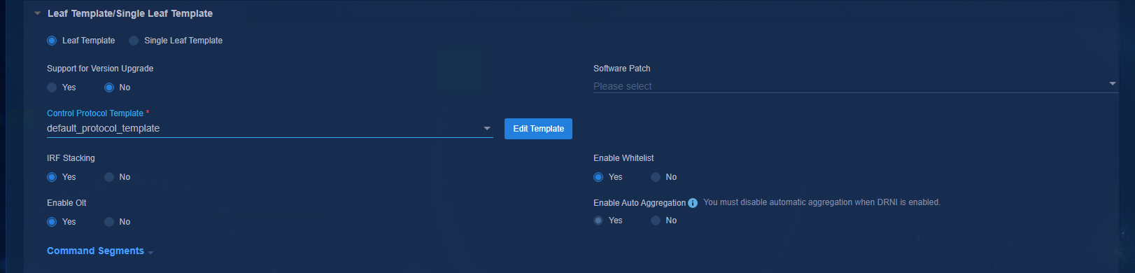
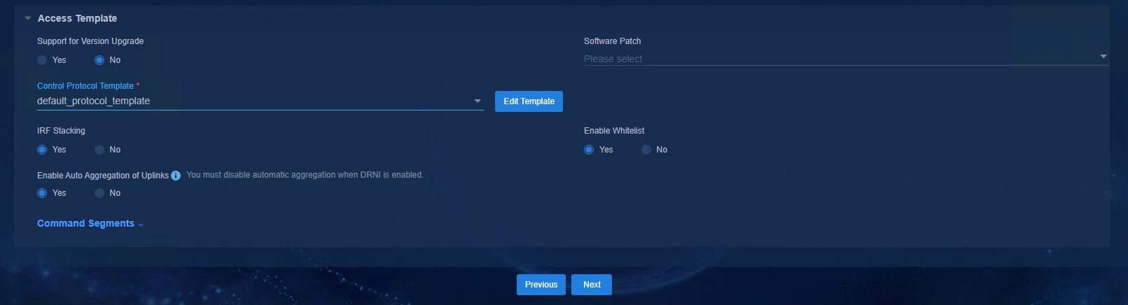
Figure 45 Access template
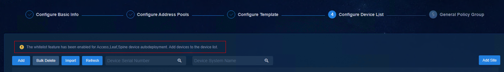
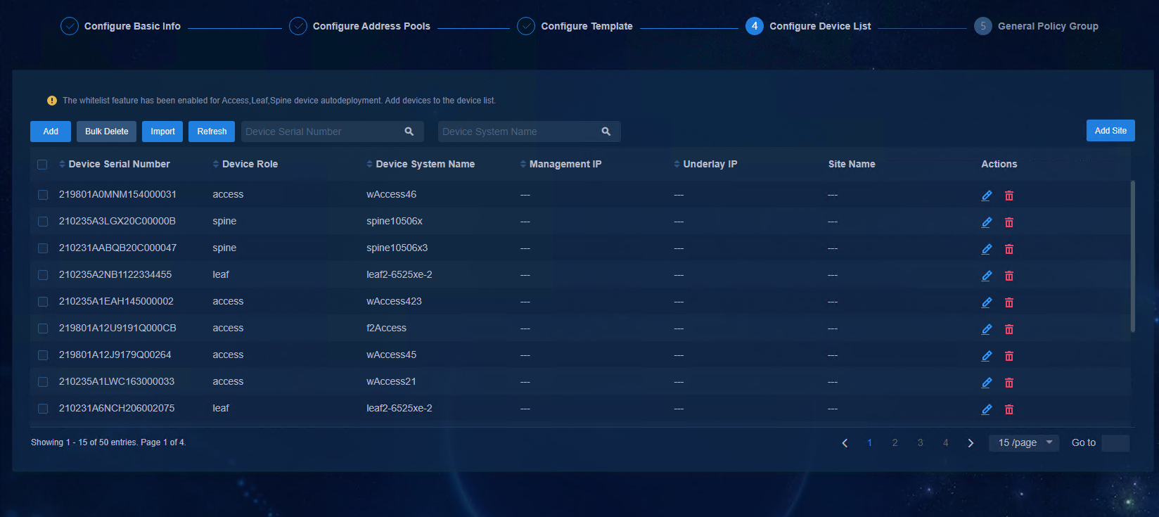
Configure a device list for automated deployment
The device list is used for the settings of the device whitelist. The device serial number is the unique identifier of each device. By setting the correspondence of the device serial number and the device role in the device list, you can plan the role information of each device.
· Used during automated device deployment when the whitelist is enabled.
¡ If the device serial number is in the device list, the device can obtain an automation template and perform automated deployment.
¡ If the device serial number is not in the device list, the device cannot obtain an automation template and cannot perform automated deployment.
· Used during automated device deployment when the whitelist is not enabled. If the device serial number is in the device list, the device performs automated deployment firstly with the role set in the whitelist. If the device serial number is not in the device list, the device performs automated deployment with the default role.
· Used when incorporating a device to the SeerEngine-Campus controller. The controller needs to match the whitelist when incorporating a device. If it does not match the whitelist, the device fails to be incorporated.
Figure 46 Device list
To add a device serial number to the device list, you can either click Add to manually add it or click Import to download the import template for batch import.
· Network Type: VXLAN (default).
· Device Serial Number: Enter the unique identifier of the device. You can obtain it by executing the following commands.
To confirm which series a device belongs to, contact Technical Support.
¡ Modular device: Fill in the serial number of the chassis and the serial number of each main processing unit. If there are multiple serial numbers, separate them with commas (,).
¡ Command for querying information about the chassis and main processing unit of the S10500X/S10500 series: display device manuinfo chassis * slot *
¡ Command for querying information about the main processing unit of the S7500E series: display device manuinfo chassis * slot *
¡ Fixed-port device (S6550XE/S6525XE/6520X/S5560X series): display license device-id slot 1
¡ Command for querying information about the main processing unit of the S7500X series: display device manuinfo chassis * slot *
¡ Fixed-port device (S51 series): display device manuinfo slot 1
· Device Role: Spine, Leaf, or Access. During automated device deployment, the device role will be modified automatically according to the role information configured in the device list.
· Device System Name: The sysname of the device, which will be modified automatically according to the configured device label.
· Management IP: (Optional) Specify the IP address of the VSI/VLAN 4094 after the device is deployed automatically.
¡ If the management IP address is configured, after the device comes online automatically, the SeerEngine-Campus controller will assign an IP address to the device according to the IP addresses configured.
¡ If the management IP address is not configured, the SeerEngine-Campus controller will automatically assign an IP address to the device according to the IP address pool of VLAN 4094.
· Underlay IP: You must fill in this field if you select No in the Auto-Allocate Underlay IP option in the automation template of Spine device. If you select Yes, you do not need to fill in this field.
· Site Name: Select the site of the device as required. If you need to use the dashboard function, you must configure the site name.
Figure 47 Device list
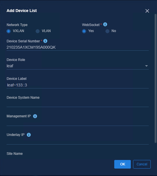
Figure 48 Configuring a device list for automated deployment
Configure the policy configuration template
The policy configuration template does not affect automated device deployment and is related to user services. For detailed configurations, see AD-Campus 6.2 Basic Configuration Guide.
Single-Leaf architecture
Configure the Layer 3 switch
For details about how to configure the Layer 3 switch in the Single-Leaf architecture, see "Configure the Layer 3 switch." The following describes how to use Leaf devices to form an IRF fabric in the Single-Leaf architecture.
1. Connect the Leaf devices to the Layer 3 switch via a cable, and interconnect all Leaf devices.
2. Set the uplink interface in the single Leaf template as a trunk port.
3. Manually configure interface aggregation on the Layer 3 switch.
#
interface Ten-GigabitEthernet0/0/48
port link-mode bridge
port link-type trunk
port trunk permit vlan all
port link-aggregation group 102
#
interface Ten-GigabitEthernet0/0/47
port link-mode bridge
port link-type trunk
port trunk permit vlan all
port link-aggregation group 102
#
interface Bridge-Aggregation102
port link-type trunk
port trunk permit vlan all
link-aggregation mode dynamic
#
4. The Leaf device acquires information about VLAN 1, and then an IRF fabric is successfully formed.
5. Connect the Leaf devices to the Layer 3 switch via the other cable, and manually configure uplink interface aggregation on the Leaf devices.
Configure the controller
The following describes the difference in configuration between the single-leaf network and spine-aggr-leaf network.
1. On the Configure Basic Info page, it is unnecessary to set RR MAC.
2. On the Configure Template page:
¡ Unselect Spine Template, select only Leaf Template/Single Leaf Template and Access Template, and select Single Leaf Template on the Leaf Template/Single Leaf Template page.
¡ Configure the uplink interface as the interface connecting the Leaf device to the Layer 3 switch.
Figure 49 Configuring device role template

Automated device deployment
Single Spine device
Start up the Spine device with no configuration
If a Spine device starts up with no configuration, it can obtain the Spine configuration template after obtaining the IP address.
Automatic configuration attempt: 3.
Interface used: Vlan-interface1.
Enable DHCP client on Vlan-interface1.
Set DHCP client identifier: 542bdead45f8-VLAN0001
Vlan-interface1 failed to obtain IP address.
Set DHCP6 client identifier: 542bdead45f8-VLAN0001
Obtained configuration file name h3c.template and TFTP server IPv6 address 130::195.// IP address of the TFTP on the controller page
Obtained an IPv6 address for Vlan-interface1: 132::8.
INFO: Get device tag file device_tag.csv success.
INFO: Read role spine from tag file.
Successfully downloaded file hefei_spine.template.// Name of the Spine template on the controller page
Executing the configuration file. Please wait...
Automatic configuration successfully completed.
Line aux0 is available.
Press ENTER to get started.
Complete automatic configuration of the Spine device
Wait for the automatic configuration of the Spine device. The device is automatically configured based on the downloaded hefei_spine.template. The IP address of VSI-interface 4094 is not included in the automatic configuration here. Use the following commands to view the automatic configuration:
[spine~133::3]dis vcf-fabric underlay autoconfigure
success command:
#
system
clock timezone beijing add 08:00:00
#
system
ip vpn-instance vpn-default
route-distinguisher 1:1
vpn-target 1:1 both
address-family evpn
vpn-target 1:1 import-extcommunity
vpn-target 1:1 export-extcommunity
address-family ipv6
vpn-target 1:1 import-extcommunity
vpn-target 1:1 export-extcommunity
#
system
lldp global enable
#
system
interface Vlan-interface1
ip address dhcp-alloc
#
system
ospfv3 1
non-stop-routing
area 0.0.0.0
#
system
interface LoopBack0
#
system
netconf soap https enable
netconf ssh server enable
restful https enable
#
system
ssh server enable
#
system
stp mode pvst
stp vlan 1 enable
undo stp vlan 2 to 4094 enable
stp global enable
stp vlan 1 priority 0
#
……
Complete automatic configuration of the AC interface
After the automation template is obtained, the physical port that connects the Spine device to the server is automatically configured as the AC interface. After the AC interface configuration is completed, the IP address of VSI-interface 4094 can be obtained.
#
interface Ten-GigabitEthernet1/0/52
port link-mode bridge
port link-type trunk
port trunk permit vlan all
#
service-instance 4094
encapsulation s-vid 4094
xconnect vsi vxlan4094
#
View main configurations of the Spine device
During automatic configuration of devices, you can view related commands on the device to check whether the IP addresses are obtained. As shown below, the IP addresses of loopback interface 0, VLAN 1, and VSI 4094 have been obtained. There is a link between the Spine device and the downlink Leaf device, so VLAN 3500 is created. (The VLAN range is determined by the Underlay VLAN range in the automation template.)
[spine~133::3]dis ipv6 interface brief
*down: administratively down
(s): spoofing
Interface Physical Protocol IPv6 Address
LoopBack0 up up(s) 51::2
M-GigabitEthernet0/0/0 down down Unassigned
Tunnel0 up up Unassigned
Tunnel1 up up Unassigned
Vlan-interface1 up up 132::8
Vlan-interface3496 up up FE80::562B:DEFF:FEAD:460A
Vlan-interface3500 up up FE80::562B:DEFF:FEAD:460E
Vsi-interface4092 up up FE80::562B:DEFF:FEAD:461E
Vsi-interface4094 up up 133::3
View information on the controller page
On the controller page, you can see that the IP address of the Spine device has been switched to 133::3, which is the IP address of VSI 4094. It also has been managed by the system and added to the Spine device group.
Figure 50 Devices
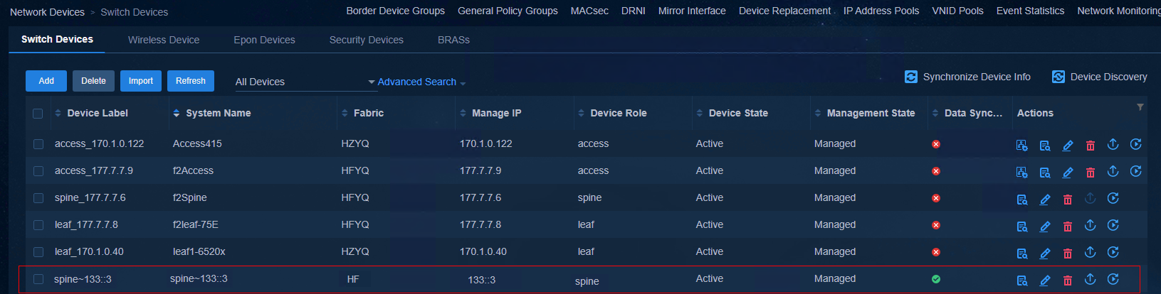
Figure 51 General device groups
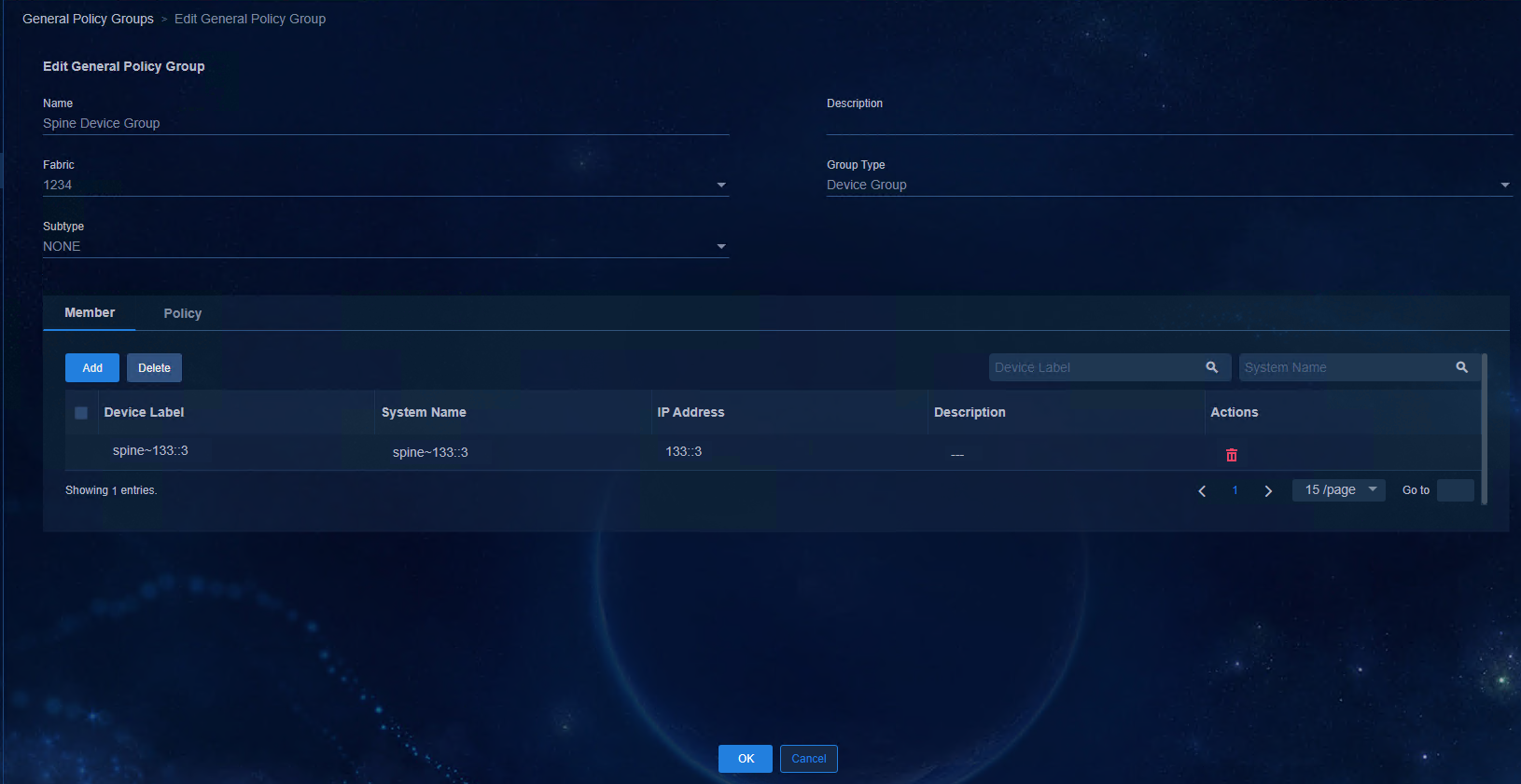
Complete automatic configuration deployment
According to automatic deployment order, when a single Spine device is deployed first, the BGP configuration is not delivered. The device will deliver the BGP configuration only when the Leaf device is automatically deployed, the Underlay OSPF of the Leaf device is established, and the IP address of the loopback interface 0 is obtained. The BGP configuration delivered here only includes the dynamic configuration related to BGP peer. The fixed configuration of BGP is delivered together with the automation template. You can use the dir command to view hefei_spine.template and the more hefei_spine.template command to view more detailed information. For more details, see "Spine device configurations".
Stacking of Spine devices
Automatic stacking of Spine devices
Prerequisites:
· The two devices support stacking.
· The two devices have an interconnection between 10 GE (or higher) ports.
· The two devices act as the same role.
To use two automatically deployed devices to form an IRF fabric:
1. Interconnect the master Spine device with the controller via a Layer 3 switch.
2. Interconnect one Spine device with the other one.
3. Deploy the device with a larger bridge MAC address first.
|
|
NOTE: It is not necessary to connect the Spine devices added later to the Layer 3 switch. You only need to connect them via the stacking links of the Spine devices that have been deployed. If you want to connect the subsequent IRF fabric of Spine devices to the Layer 3 switch, you need to manually configure the interface aggregation on the Layer 3 switch, and specify the trunk port as the uplink interface in the Spine template. |
Spine device 1:
%Feb 19 08:09:58:256 2021 spine~133::8 VCF/4/VCF_FAILED_ADD_IRFPORT: In phase 2.0.10, device with MAC address 542b-dead-45f8 add IRF port GigabitEthernet1/0/7 has failed three times.
%Feb 19 08:10:40:251 2021 spine~133::8 VCF/5/VCF_IRF_START: In phase 2.0.2, device with MAC address 542b-dead-45f8 started IRF configuration: Current member ID 1, new member ID 1, priority 2, ['Ten-GigabitEthernet1/0/49'] bound to IRF-port 1, [None] bound to IRF-port 2.
%Feb 19 08:10:14:711 2021 spine~133::8 VCF/5/VCF_IRF_FINISH: In phase 2.0.3, device with MAC address 542b-dead-45f8 finished IRF configuration with peer 4ce9-e498-16cb. The result is 0.
Spine device 2:
<spine-132::4>%Feb 19 08:10:18:362 2021 spine-132::4 VCF/5/VCF_IRF_START: In phase 2.0.2, device with MAC address 4ce9-e498-16cb started IRF configuration: Current member ID 1, new member ID 5, priority 1, [None] bound to IRF-port 1, ['GigabitEthernet1/0/2', 'Ten-GigabitEthernet1/0/49'] bound to IRF-port 2.
%Feb 19 08:10:59:621 2021 spine-132::4 VCF/5/VCF_IRF_FOUND: In phase 2.0.1, device with MAC address 4ce9-e498-16cb found peer 542b-dead-45f8 with the same role spine. Availability of IRF configuration is 0.
%Feb 19 08:11:20:874 2021 spine-132::4 VCF/5/VCF_IRF_FINISH: In phase 2.0.3, device with MAC address 4ce9-e498-16cb finished IRF configuration with peer 542b-dead-45f8. The result is 0.
After the standby device restarts, the IRF fabric is set up successfully.
%Feb 19 08:11:25:241 2021 spine-132::4 VCF/5/VCF_REBOOT: Phase 2.0.4, Device 542b-dead-45f8 will reboot. Reason: IRF fabric setup success.
%Feb 19 08:11:27:488 2021 spine-132::4 SYSLOG/5/LOGFILE_USAGEHIGH: The usage of log-file flash:/logfile/logfile.log reaches 80%.
%Feb 19 08:11:28:371 2021 spine-132::4 DEV/5/SYSTEM_REBOOT: System is rebooting now.
%Feb 19 08:15:49:712 2021 spine~133::8 VCF/5/VCF_IRF_ALREADY: In phase 2.0.10, device with MAC address 542b-dead-45f8 has been irf successfully, standby Mac 4ce9-e498-16cb.
<spine~133::8>dis irf
MemberID Role Priority CPU-Mac Description
*+1 Master 2 f010-90db-7402 ---
5 Standby 1 f010-90db-7406 ---
--------------------------------------------------
* indicates the device is the master.
+ indicates the device through which the user logs in.
The bridge MAC of the IRF is: 542b-dead-45f8
Auto upgrade : yes
Mac persistent : always
Domain ID : 0
After the IRF fabric is successfully set up, the system automatically starts BFD configuration.
%Feb 19 08:17:13:491 2021 spine~133::8 IFNET/3/PHY_UPDOWN: Physical state on the interface Vlan-interface100 changed to up.
%Feb 19 08:17:13:500 2021 spine~133::8 IFNET/5/LINK_UPDOWN: Line protocol state on the interface Vlan-interface100 changed to up.
%Feb 19 08:18:14:574 2021 spine~133::8 BFD/5/BFD_MAD_INTERFACE_CHANGE_STATE: BFD MAD function enabled on Vlan-interface100 changed to the normal state.
When there is more than one stacking link on the device, one of the links is used as the BFD detection link, and the following configuration is delivered to the physical port.
#
interface GigabitEthernet1/0/7
port link-mode bridge
port access vlan 100
undo stp enable
#
interface GigabitEthernet5/0/2
port link-mode bridge
port access vlan 100
undo stp enable
#
Configure VLAN-interface 100, configure MAD IP addresses for all member devices in the IRF, and bind them with member numbers.
#
interface Vlan-interface100
mad bfd enable
mad ip address 192.168.100.1 255.255.255.0 member 1
mad ip address 192.168.100.2 255.255.255.0 member 5
#
Enable BFD MAD globally on the devices.
[spine~133::8]mad bfd enable
Multiple links between Spine and Leaf devices
If there are multiple links between Spine devices and Leaf devices, the multiple links are automatically configured with ECMP, regardless of the timing.
[spine~133::8]dis ll n l | include leaf
GE5/0/29 b0f9-63b3-20fe GigabitEthernet5/0/20 leaf~133::C
GE5/0/37 b0f9-63b3-20fe GigabitEthernet5/0/33 leaf~133::C
[spine~133::8]display vcf-fabric underlay autoconfigure
Downlink interface:
GigabitEthernet5/0/29
GigabitEthernet5/0/37
IRF allocation:
Self Bridge Mac: 542b-dead-45f8
IRF Status: Yes
Member List: [5, 1]
BFD Mad-port pairs: GE1/0/7 , GE5/0/2
VLAN ID Allocation:
VLAN range: 3001-3500
VLAN exist and system reserved:
[1]
Interface VLAN ID
GigabitEthernet5/0/37 3497
GigabitEthernet5/0/29 3498
View the routing table where equal-cost routes have been generated.
[spine~133::8]dis ipv6 routing-table
Destinations : 10 Routes : 11
Destination: ::/0 Protocol : Direct
NextHop : FE80::562B:DEFF:FED6:BB83 Preference: 80
Interface : Vlan1 Cost : 0
Destination: ::1/128 Protocol : Direct
NextHop : ::1 Preference: 0
Interface : InLoop0 Cost : 0
Destination: 51::1/128 Protocol : Direct
NextHop : ::1 Preference: 0
Interface : InLoop0 Cost : 0
Destination: 51::2/128 Protocol : O_INTRA
NextHop : FE80::B2F9:63FF:FEB3:2111 Preference: 10
Interface : Vlan3497 Cost : 1
Destination: 51::2/128 Protocol : O_INTRA
NextHop : FE80::B2F9:63FF:FEB3:2112 Preference: 10
Interface : Vlan3498 Cost : 1
Single Leaf device
Start up the Leaf device with no configuration
If a Leaf device starts up with no configuration, it can obtain the Leaf configuration template after obtaining the IP address.
Automatic configuration attempt: 1.
Interface used: Vlan-interface1.
Enable DHCP client on Vlan-interface1.
Set DHCP client identifier: 4ce9e49816cb-VLAN0001
Vlan-interface1 failed to obtain IP address.
Set DHCP6 client identifier: 4ce9e49816cb-VLAN0001
Obtained configuration file name hefei.template and TFTP server IPv6 address 130::195.// The TFTP address of the controller.
Obtained an IPv6 address for Vlan-interface1: 132::A.
INFO: Get device tag file device_tag.csv success.
INFO: Read role leaf from tag file.
Successfully downloaded file hefei_leaf.template.// Name of the Leaf template on the controller page.
Executing the configuration file. Please wait...
Automatic configuration successfully completed.
Line aux0 is available.
Press ENTER to get started.
Wait for automatic configuration of the Leaf device. The device delivers the automatic configuration commands based on the hefei_leaf.template. You can use the dir command to view hefei_leaf.template and the more hefei_leaf.template command to view more detailed information. For more details, see "Leaf device configurations".
Deliver configurations to the interface on the leaf device
Deliver the corresponding configuration to the uplink and downlink interfaces that are dynamically identified.
Uplink interface: Configure VLAN 3496. If there are multiple uplink interfaces, ECMP is configured.
#
interface GigabitEthernet1/0/7
port link-mode bridge
port link-type trunk
port trunk permit vlan 1 3496
#
Downlink interface: After the Access device is deployed automatically, the downlink interface is configured as a trunk port and bound to service instance 4094.
#
interface GigabitEthernet1/0/29
port link-mode bridge
port link-type trunk
port trunk permit vlan 1 to 99 101 to 4094
stp tc-restriction
#
service-instance 4094
encapsulation s-vid 4094
xconnect vsi vxlan4094
#
View main configurations of the Leaf device
During automated device deployment, you can view related commands to check whether the IP addresses are obtained. The Leaf device obtains the IP addresses of VLAN 1 and the loopback interface. VLAN is automatically assigned to the interconnect interface between the Leaf device and the Spine device, and its IP address uses the IP address of the loopback interface. (The VLAN range is determined by the Underlay VLAN range in the automation template.)
View the IP addresses on the device to see if they are successfully obtained.
[leaf~133::5]dis ipv6 interface brief
*down: administratively down
(s): spoofing
Interface Physical Protocol IPv6 Address
LoopBack0 up up(s) 51::3
M-GigabitEthernet0/0/0 down down Unassigned
Tunnel0 up up Unassigned
Tunnel1 up up Unassigned
Vlan-interface1 up up 132::A
Vlan-interface3496 up up FE80::4EE9:E4FF:FE98:16DD
Vsi-interface4092 up up FE80::4EE9:E4FF:FE98:16F1
Vsi-interface4094 up up 133::5
Check the peer establishment status between the Leaf device and Spine device after the OSPFv3 configuration in the automation template is delivered.
#
interface Vlan-interface3496
mtu 4094
ospfv3 1 area 0.0.0.0
ospfv3 network-type p2p
ipv6 address auto link-local
#
[leaf~133::5]dis ospfv3 peer
OSPFv3 Process 1 with Router ID 66.0.0.5
Area: 0.0.0.0
-------------------------------------------------------------------------
Router ID Pri State Dead-Time InstID Interface
66.0.0.1 1 Full/ - 00:00:36 0 Vlan3500
After discovering the Leaf device via the master RR device (the specified Spine device), the system will automatically assign the configuration of BGP 100 to the Spine device and Leaf device, and establish BGP peers. The corresponding BGP configuration on the Leaf device is as follows:
#
bgp 100
non-stop-routing
router-id 66.0.0.5
peer 51::2 as-number 100
peer 51::2 connect-interface LoopBack0
#
address-family l2vpn evpn
peer 51::2 enable
#
ip vpn-instance vpn-default
#
address-family ipv4 unicast
#
address-family ipv6 unicast#
Establish EVPN peers between the Leaf device and Spine device.
[leaf~133::4]display bgp peer l2vpn evpn
BGP local router ID: 66.0.0.5
Local AS number: 100
Total number of peers: 1 Peers in established state: 1
* - Dynamically created peer
^ - Peer created through link-local address
Peer AS MsgRcvd MsgSent OutQ PrefRcv Up/Down State
51::2 100 20 17 0 14 00:09:54 Established
VSI 4094 can obtain the IP address of the DHCP server only when the EVPN peers are successfully established and the VXLAN tunnels are UP. Finally, the IP addresses on the device are successfully obtained.
View information on the controller page
After the IP address of VSI 4094 is successfully obtained, you can see that the Leaf device, whose IP address has been switched to that of VSI 4094, has been managed by the controller. In addition, the device has been added to the Leaf device group and the Leaf device group will automatically deploy VLAN 101 to VLAN 3000 to the new device.
The IP address of the Leaf device switches from VLAN 1 to VSI 4094 to be managed by the system.
Figure 52 Device
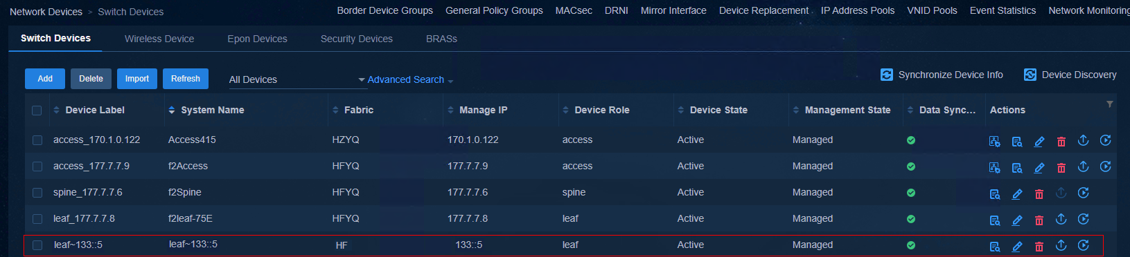
The device is automatically added to the Leaf device group.
Figure 53 Leaf device group

Figure 54 Leaf downlink interface group

The Leaf interface is automatically added to the Leaf downlink interface group.
Figure 55 Leaf downlink interface group
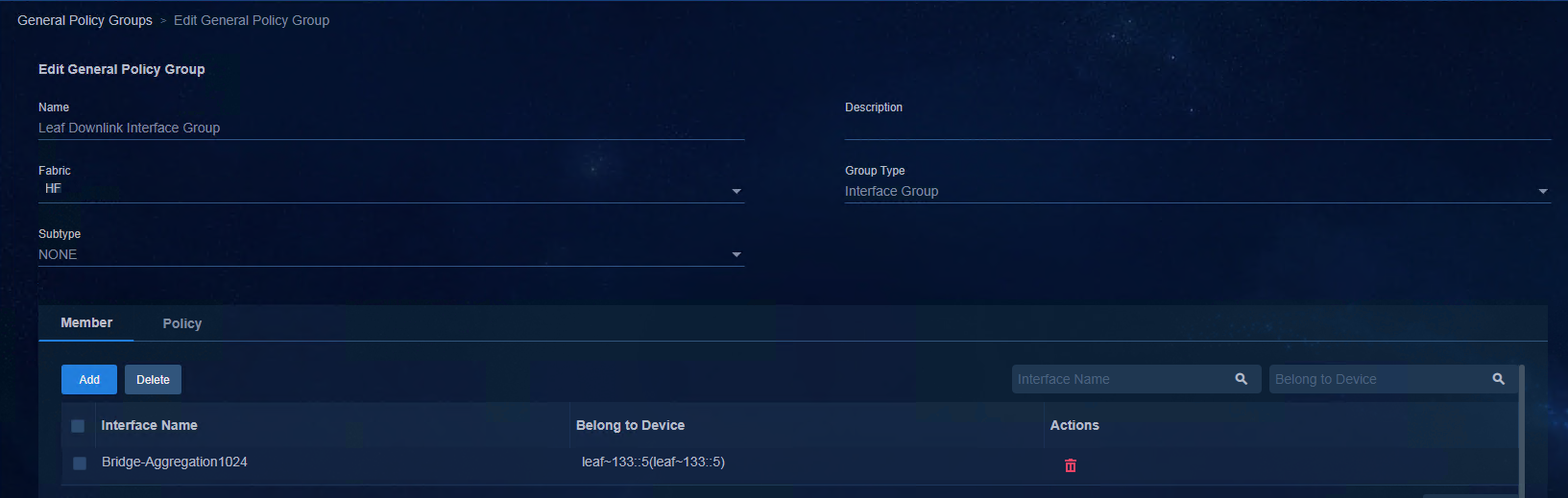
VLAN 101 to VLAN 3000 and VLAN 3496 are allocated on the Leaf device.
[leaf~133::4]dis vlan
Total VLANs: 2903
The VLANs include:
1(default), 101-3000, 3496, 4094
Multiple Leaf devices
For automated deployment of multiple Leaf devices, pay attention to the deployment of BGP configurations. For users, the configuration deployment is an automated process. Therefore, the users only need to view the management state of the devices on the controller page. EVPN neighbors and VXLAN tunnels will be automatically established after the BGP configurations are deployed on the devices.
The following provides the EVPN neighbor status on the Spine devices after automated deployment of two Leaf devices:
[spine~133::3]display bgp peer l2vpn evpn
BGP local router ID: 66.0.0.1
Local AS number: 100
Total number of peers: 2 Peers in established state: 2
* - Dynamically created peer
^ - Peer created through link-local address
Peer AS MsgRcvd MsgSent OutQ PrefRcv Up/Down State
51::1 100 47 55 0 3 00:39:03 Established
51::3 100 15 18 0 5 00:08:01 Established
VXLAN tunnel status viewed on the Spine device:
[spine~133::3]dis interface Tunnel
Tunnel0
Current state: UP
Line protocol state: UP
Description: Tunnel0 Interface
Bandwidth: 64 kbps
Maximum transmission unit: 4038
Internet protocol processing: Disabled
Last clearing of counters: Never
Tunnel source 51::2, destination 51::1
Tunnel protocol/transport UDP_VXLAN/IPv6
Last 300 seconds input rate: 0 bytes/sec, 0 bits/sec, 0 packets/sec
Last 300 seconds output rate: 0 bytes/sec, 0 bits/sec, 0 packets/sec
Input: 134 packets, 11750 bytes, 0 drops
Output: 11 packets, 1278 bytes, 0 drops
Tunnel1
Current state: UP
Line protocol state: UP
Description: Tunnel1 Interface
Bandwidth: 64 kbps
Maximum transmission unit: 4038
Internet protocol processing: Disabled
Last clearing of counters: Never
Tunnel source 51::2, destination 51::3
Tunnel protocol/transport UDP_VXLAN/IPv6
Last 300 seconds input rate: 0 bytes/sec, 0 bits/sec, 0 packets/sec
Last 300 seconds output rate: 0 bytes/sec, 0 bits/sec, 0 packets/sec
Input: 0 packets, 0 bytes, 0 drops
Output: 0 packets, 0 bytes, 0 drops
IRF stacking of Leaf devices
Automatic IRF stacking of Leaf devices
Prerequisites:
· The two devices support stacking.
· The two devices have an interconnection between 10 GE (or higher) ports.
· The two devices act as the same role.
To use two automatically deployed devices to form an IRF fabric:
1. Interconnect the Leaf devices with the Spine devices.
2. Interconnect one Leaf device with the other one.
3. Clear the configurations of the two devices and restart them.
If Leaf device 1 detects a connection with a rate of 10 GE or higher to Leaf device 2, and the two devices have the same role, the two devices form an IRF fabric automatically.
Leaf device 1:
%Mar 5 09:57:12:753 2021 H3C VCF/5/VCF_IRF_FOUND: In phase 2.0.1, device with MAC address 4ce9-e498-1803 found peer b0f9-63b3-20fe with the same role leaf. Availability of IRF configuration is 0.
%Mar 5 09:57:40:810 2021 H3C VCF/5/VCF_IRF_START: In phase 2.0.2, device with MAC address 4ce9-e498-1803 started IRF configuration: Current member ID 1, new member ID 5, priority 1, [None] bound to IRF-port 1, ['GigabitEthernet1/0/43', 'Ten-GigabitEthernet1/0/49'] bound to IRF-port 2.priority 1, [None] bound to IRF-port 1, ['Ten-GigabitEthernet5/1/17'] bound to IRF-port 2.
%Mar 5 09:58:42:135 2021 leaf-132::9 VCF/5/VCF_IRF_FINISH: In phase 2.0.3, device with MAC address 4ce9-e498-1803 finished IRF configuration with peer b0f9-63b3-20fe. The result is 0.
Leaf device 2:
%Mar 5 09:56:14:280 2021 H3C VCF/5/VCF_IRF_FOUND: In phase 2.0.1, device with MAC address b0f9-63b3-20fe found peer 4ce9-e498-1803 with the same role leaf. Availability of IRF configuration is 0.
%Mar 5 09:56:54:556 2021 H3C VCF/5/VCF_IRF_START: In phase 2.0.2, device with MAC address b0f9-63b3-20fe started IRF configuration: Current member ID 1, new member ID 1, priority 2, ['GigabitEthernet1/0/13', 'Ten-GigabitEthernet1/0/49'] bound to IRF-port 1, [None] bound to IRF-port 2.
%Mar 5 09:57:55:845 2021 leaf-132::8 VCF/5/VCF_IRF_FINISH: In phase 2.0.3, device with MAC address b0f9-63b3-20fe finished IRF configuration with peer 4ce9-e498-1803. The result is 0.
After the standby device restarts, the IRF fabric is set up successfully.
%Mar 5 09:58:46:607 2021 leaf-132::9 VCF/5/VCF_REBOOT: Phase 2.0.4, Device b0f9-63b3-20fe will reboot. Reason: IRF fabric setup success.
%Mar 5 09:58:49:102 2021 leaf-132::9 SYSLOG/5/LOGFILE_USAGEHIGH: The usage of log-file flash:/logfile/logfile.log reaches 80%.
%Mar 5 09:58:50:428 2021 leaf-132::9 DEV/5/SYSTEM_REBOOT: System is rebooting now.
<leaf~133::C>dis irf
MemberID Role Priority CPU-Mac Description
*1 Master 2 f010-90db-7402 ---
+5 Standby 1 f010-90db-7406 ---
--------------------------------------------------
* indicates the device is the master.
+ indicates the device through which the user logs in.
The bridge MAC of the IRF is: b0f9-63b3-20fe
Auto upgrade : yes
Mac persistent : always
Domain ID : 0
After the IRF fabric is successfully set up, the system automatically starts BFD configuration:
%Mar 5 10:04:03:440 2021 leaf-132::8 LLDP/6/LLDP_CREATE_NEIGHBOR: -Slot=5; Nearest bridge agent neighbor created on port GigabitEthernet5/0/43 (IfIndex 295), neighbor's chassis ID is b0f9-63b3-20fe, port ID is GigabitEthernet1/0/13.
%Mar 5 10:04:03:497 2021 leaf-132::8 LLDP/6/LLDP_CREATE_NEIGHBOR: Nearest bridge agent neighbor created on port GigabitEthernet1/0/13 (IfIndex 13), neighbor's chassis ID is b0f9-63b3-20fe, port ID is GigabitEthernet5/0/43.
%Mar 5 10:04:16:401 2021 leaf-132::8 IFNET/3/PHY_UPDOWN: Physical state on the interface Vlan-interface100 changed to up.
%Mar 5 10:04:16:401 2021 leaf-132::8 IFNET/5/LINK_UPDOWN: Line protocol state on the interface Vlan-interface100 changed to up.
%Mar 5 10:05:17:211 2021 leaf-132::8 BFD/5/BFD_MAD_INTERFACE_CHANGE_STATE: BFD MAD function enabled on Vlan-interface100 changed to the normal state.
One of the stacking links on the device is used as the BFD detection link, and the following configuration is delivered to the physical port:
#
interface GigabitEthernet1/0/13
port link-mode bridge
port access vlan 100
undo stp enable
undo lldp enable
#
interface GigabitEthernet5/0/43
port link-mode bridge
port access vlan 100
undo stp enable
undo lldp enable
#
Configure L3 VLAN-interface 100, configure MAD IP addresses for all member devices in the IRF, and bind them with member numbers.
#
interface Vlan-interface100
mad bfd enable
mad ip address 192.168.100.1 255.255.255.0 member 1
mad ip address 192.168.100.2 255.255.255.0 member 5
#
Enable BFD MAD globally on the devices.
[leaf~133::C]mad bfd enable
Add links between Leaf and Spine devices
After using Spine and Leaf devices to form an IRF fabric, ECMP is automatically configured if new links are added between these devices. After links are added, the link information is as follows:
[leaf~133::C]dis ipv6 routing-table
Destinations : 10 Routes : 11
Destination: ::/0 Protocol : Direct
NextHop : FE80::562B:DEFF:FED6:BB83 Preference: 80
Interface : Vlan1 Cost : 0
Destination: ::1/128 Protocol : Direct
NextHop : ::1 Preference: 0
Interface : InLoop0 Cost : 0
Destination: 51::1/128 Protocol : O_INTRA
NextHop : FE80::562B:DEFF:FEAD:460B Preference: 10
Interface : Vlan3497 Cost : 1
Destination: 51::1/128 Protocol : O_INTRA
NextHop : FE80::562B:DEFF:FEAD:460C Preference: 10
Interface : Vlan3498 Cost : 1
[leaf~133::C]dis vlan
Total VLANs: 2905
The VLANs include:
1(default), 100-3000, 3497-3498, 4094
[leaf~133::C]dis vcf-fabric underlay autoconfigure
Uplink interface:
GigabitEthernet5/0/20
GigabitEthernet5/0/33
IRF allocation:
Self Bridge Mac: b0f9-63b3-20fe
IRF Status: Yes
Member List: [5, 1]
BFD Mad-port pairs: GE1/0/13 , GE5/0/43
VLAN ID Allocation:
Interface VLAN ID
GigabitEthernet5/0/33 3497
GigabitEthernet5/0/20 3498
Add links between Leaf and Access devices
|
|
NOTE: The number of auto-aggregated links is limited to two physical links. |
If you add a link between Leaf and Access devices, multiple links are automatically aggregated.
%Mar 5 12:58:55:405 2021 access-132::9 LAGG/6/LAGG_ACTIVE: Member port GE1/0/13 of aggregation group BAGG1024 changed to the active state.
%Mar 5 12:59:02:833 2021 access-132::9 IFNET/3/PHY_UPDOWN: Physical state on the interface Bridge-Aggregation1024 changed to up.
%Mar 5 12:59:02:842 2021 access-132::9 IFNET/5/LINK_UPDOWN: Line protocol state on the interface Bridge-Aggregation1024 changed to up.
%Mar 5 12:58:59:630 2021 access-132::9 VCF/6/VCF_AGGR_CREATE: In phase 2.0.5, device with MAC address b0f9-63b3-20fe created aggregation group 1024. The member port list is GigabitEthernet1/0/13,GigabitEthernet1/0/21.
[leaf~133::5]dis ll n l | include access
GE5/0/35 b0f9-63b3-20fe GigabitEthernet1/0/13 access~133::2
GE5/0/41 b0f9-63b3-20fe GigabitEthernet1/0/21 access~133::2
The controller will automatically delete the configuration of the original member port and deploy the configuration of the downlink interface of the Leaf device on the aggregation port.
#
interface GigabitEthernet5/0/35
port link-mode bridge
port link-type trunk
port trunk permit vlan 1 to 99 101 to 4094
port link-aggregation group 1024
#
interface GigabitEthernet5/0/41
port link-mode bridge
port link-type trunk
port trunk permit vlan 1 to 99 101 to 4094
port link-aggregation group 1024
#
interface Bridge-Aggregation1024
port link-type trunk
port trunk permit vlan 1 to 99 101 to 4094
link-aggregation mode dynamic
stp tc-restriction
#
service-instance 4094
encapsulation s-vid 4094
xconnect vsi vxlan4094
#
Single Access device
|
|
NOTE: · Before the automated deployment of the Access device, the Leaf device connecting to its uplink interface must complete automated deployment and be activated first. · If the Access device is incorporated manually, the Leaf device connecting to its uplink interface must be incorporated and activated first. · If the automated device deployment fails, clear the configuration of the device and perform automated deployment again. |
Start up the Access device with no configuration
If the Access device starts up with no configuration, it obtains the IP address of VLAN 1 via the Leaf device and then obtains the automated deployment template.
Automatic configuration attempt: 1.
Interface used: Vlan-interface1.
Enable DHCP client on Vlan-interface1.
Set DHCP client identifier: 4ce9e4981803-VLAN0001
Vlan-interface1 failed to obtain IP address.
Set DHCP6 client identifier: 4ce9e4981803-VLAN0001
Obtained configuration file name hefei.template and TFTP server IPv6 address 130::195.// The TFTP address of the controller.
Obtained an IPv6 address for Vlan-interface1: 132::3.
INFO: Get device tag file device_tag.csv success.
INFO: Read role access from tag file.
Successfully downloaded file hefei_access.template.//Device template.
Executing the configuration file. Please wait...
Automatic configuration successfully completed.
Line aux0 is available.
Press ENTER to get started.
Complete automatic configuration of the Access device
Wait for automatic configuration of the Access device, which executes the automatic configuration command based on the hangzhou_access.template. Each downlink interface of the Access device is allocated with a unique PVID during automated deployment. If the device is a switch that supports PoE, the PoE function is enabled for ports. You can use the dir command to view hefei_access.template and the more hefei_access.template command to view more detailed information. For more details, see "Access device configurations".
View main configuration of the Access device
Wait for the automated deployment of the Access device. The IP addresses of VLAN 1 and VLAN 4094 are successfully obtained.
[access~133::8]dis ipv6 interface brief
*down: administratively down
(s): spoofing
Interface Physical Protocol IPv6 Address
M-GigabitEthernet0/0/0 down down Unassigned
Vlan-interface1 up up 132::3
Vlan-interface4094 up up 133::8
The uplink interface of the Access device is set to Trunk all.
#
interface GigabitEthernet1/0/20
port link-mode bridge
port link-type trunk
port trunk permit vlan all
#
If the device supports PoE, the PoE function is enabled for all interfaces. If an AP device is detected, VLAN 4093 will be configured and the downlink interface of the Access device is configured with PVID 4093.
#
interface GigabitEthernet1/0/20
port link-mode bridge
port link-type trunk
port trunk permit vlan all
poe enable
#
View information on the controller page
When you view the device information on the controller, you can see that the Access device, whose IP address has been switched from VLAN 1 to VLAN 4094, has been managed by the controller.
Figure 56 Device

The device is also automatically added to the Access device group.
Figure 57 Access device group
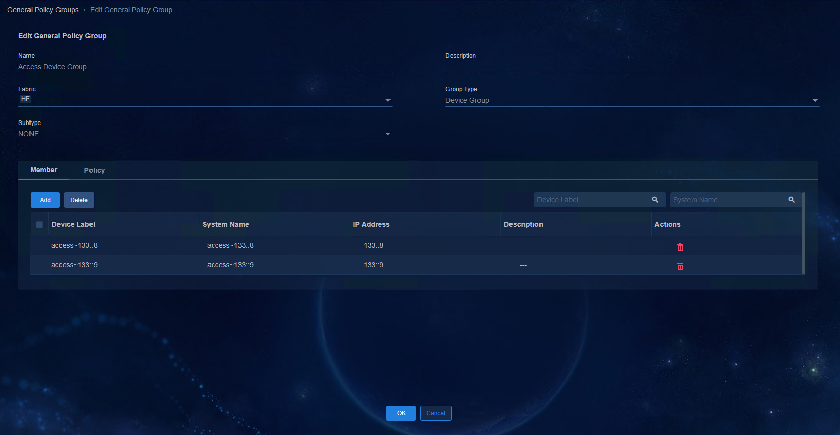
IRF stacking of Access devices
Automatic IRF stacking of Access devices
To use two automatically deployed devices to form an IRF fabric:
1. Interconnect the Access devices with the Leaf device.
2. Interconnect the two devices via one cable.
3. Clear the configurations of the two devices and restart them.
After adding another Access device for automated deployment, the two devices automatically form an IRF fabric if Access device 1 detects a 10 GE connection with Access device 2 and the two devices have the same role.
[access~133::7]dis irf
MemberID Role Priority CPU-Mac Description
*+1 Master 2 f010-90db-7402 ---
5 Standby 1 f010-90db-7406 ---
--------------------------------------------------
* indicates the device is the master.
+ indicates the device through which the user logs in.
The bridge MAC of the IRF is: b0f9-63b3-20fe
Auto upgrade : yes
Mac persistent : always
Domain ID : 0
|
|
NOTE: At present, the IRF stacking of Access devices does not support automated configuration of BFD MAD. If necessary, you need to manually configure BFD MAD. |
To manually configure BFD MAD:
4. After an IRF is formed, ensure that the physical port of BFD is down, and configure BFD on the physical ports of the IRF fabric composed of Access devices.
#
vlan 100 // Dedicated for BFD MAD.
#
#
interface Ten-GigabitEthernet 1/0/49
port link-type trunk
undo port trunk permit vlan 1
port trunk permit vlan 100
undo stp enable
stp edged-port //The controller will audit the difference if this command is not configured.
undo lldp enable
#
#
interface Ten-GigabitEthernet 5/0/49
port link-type trunk
undo port trunk permit vlan 1
port trunk permit vlan 100
undo stp enable
stp edged-port //The controller will audit the difference if this command is not configured.
undo lldp enable
#
#
interface Vlan-interface100
mad bfd enable
mad ip address 192.168.100.1 255.255.255.0 member 1
mad ip address 192.168.100.5 255.255.255.0 member 5
#
5. Interconnect the two ports that need to configure BFD and check the state of BFD MAD.
[5130s-hi-down]disp mad verbose
Multi-active recovery state: No
Excluded ports (user-configured):
Excluded ports (system-configured):
IRF physical interfaces:
Ten-GigabitEthernet1/0/49
Ten-GigabitEthernet5/0/49
BFD MAD interfaces:
GigabitEthernet1/0/13
GigabitEthernet5/0/43
Vlan-interface100
MAD ARP disabled.
MAD ND disabled.
MAD LACP disabled.
MAD BFD enabled interface: Vlan-interface99
MAD status : Normal
Member ID MAD IP address Neighbor MAD status
1 192.168.100.1/24 5 Normal
5 192.168.100.5/24 1 Normal
Automatic link aggregation between Leaf and Access devices
|
|
NOTE: The number of auto-aggregated links is limited to two physical links. |
[access~133::2]dis ll n l | include leaf
GE1/0/13 4ce9-e498-16cb GigabitEthernet5/0/35 leaf~133::5
GE1/0/21 4ce9-e498-16cb GigabitEthernet5/0/41 leaf~133::5
[access~133::2]dis vlan brief
Brief information about all VLANs:
Supported Minimum VLAN ID: 1
Supported Maximum VLAN ID: 4094
Default VLAN ID: 1
VLAN ID Name Port
1 VLAN 0001 BAGG1024(U) GE1/0/13(U)
GE1/0/21(U)
101 VLAN 0101 BAGG1024(U) GE1/0/1(D)
GE1/0/13(U) GE1/0/21(U)
102 VLAN 0102 BAGG1024(U) GE1/0/2(D)
GE1/0/13(U) GE1/0/21(U)
[access~133::2]dis link-aggregation verbose
Loadsharing Type: Shar -- Loadsharing, NonS -- Non-Loadsharing
Port Status: S -- Selected, U -- Unselected, I -- Individual
Port: A -- Auto port, M -- Management port, R -- Reference port
Flags: A -- LACP_Activity, B -- LACP_Timeout, C -- Aggregation,
D -- Synchronization, E -- Collecting, F -- Distributing,
G -- Defaulted, H -- Expired
Aggregate Interface: Bridge-Aggregation1024
Creation Mode: Manual
Aggregation Mode: Dynamic
Loadsharing Type: Shar
Management VLANs: None
System ID: 0x8000, b0f9-63b3-20fe
Local:
Port Status Priority Index Oper-Key Flag
GE1/0/13 S 32768 1 1 {ACDEF}
GE1/0/21 S 32768 2 1 {ACDEF}
Remote:
Actor Priority Index Oper-Key SystemID Flag
GE1/0/13(R) 32768 1 1 0x8000, 4ce9-e498-16cb {ACDEF}
GE1/0/21 32768 2 1 0x8000, 4ce9-e498-16cb {ACDEF}
Cascading of Access devices
If the Access device needs to be cascaded, the GE port must be used for cascading. The Access device directly connected to the Leaf device is called the level-1 Access device, and the Level-1 Access device is cascaded with the level-2 Access device, and so on. The current version supports up to three levels of cascading. The automated deployment process of the level-2 Access device is similar to that of the level-1 Access device.
|
|
NOTE: · During automated deployment of the level-1 Access device, the downlink interface is automatically configured as a PVID started from 101 (101 to 3000). However, if a level-2 Access device is cascaded to the level-1 Access device, the PVID will be restored to 1 once the level-1 Access device detects that the downlink interface is UP and the device is an H3C switch, to ensure the automated deployment of the level-2 Access device. If the device is a non-H3C device, manually set PVID to 1. · The number of auto-aggregated links of the cascading Access device is limited to two physical links. |
Start up the cascaded Access devices with no configuration
If the cascaded Access devices start up with no configuration, the automated deployment process is as follows:
Startup configuration file doesn't exist or is invalid.
Performing automatic configuration... Press CTRL_C or CTRL_D to break.
Automatic configuration attempt: 1.
Interface used: Vlan-interface1.
Enable DHCP client on Vlan-interface1.
Set DHCP client identifier: b0f963b320fe-VLAN0001
Vlan-interface1 failed to obtain IP address.
Set DHCP6 client identifier: b0f963b320fe-VLAN0001
Obtained configuration file name hefei.template and TFTP server IPv6 address 130::195.
Obtained an IPv6 address for Vlan-interface1: 132::7.
INFO: Get device tag file device_tag.csv success.
INFO: Read role access from tag file.
Successfully downloaded file hefei_access.template.
Executing the configuration file. Please wait...
Automatic configuration successfully completed.
Line aux0 is available.
Press ENTER to get started.
View and check the deployment information
View the obtained IP addresses of VLAN-interface 1 and VLAN-interface 4094.
<access~133::9>dis ipv6 interface brief
*down: administratively down
(s): spoofing
Interface Physical Protocol IPv6 Address
M-GigabitEthernet0/0/0 down down Unassigned
Vlan-interface1 up up 132::7
Vlan-interface4094 up up 133::9
On the controller page, you can see that the added level-2 Access device has been managed.
Figure 58 Device
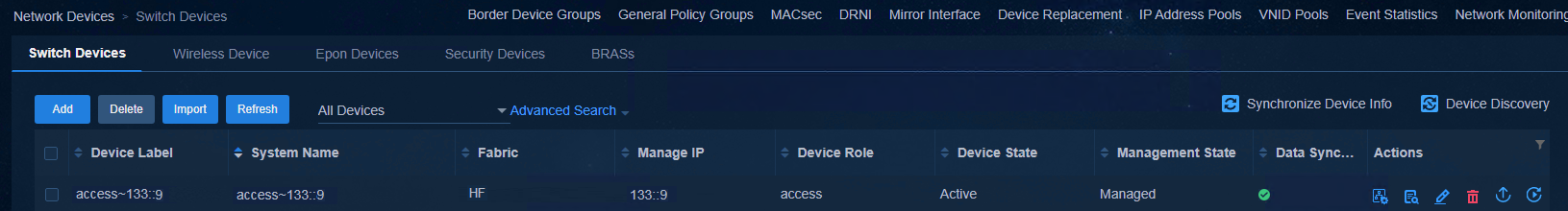
The level-2 Access device is also automatically imported to the Access device group.
Figure 59 Access device group
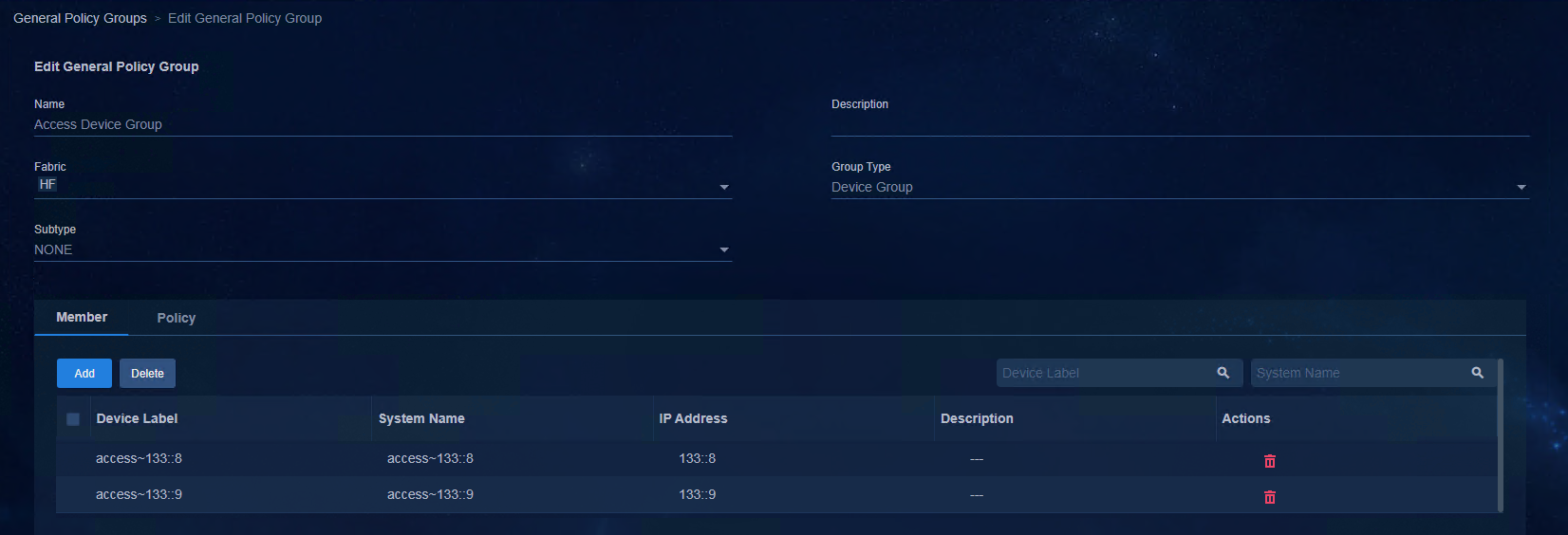
Configure the security group
Add a DHCPv6 server in the isolation domain
Access
Automation > Campus Network > Isolation Domain > Isolation
Domain page, and click Add to add an isolation domain, or click the Edit
icon ![]() in the actions column to edit the
isolation domain. This document takes the editing of the isolation domain as an
example.
in the actions column to edit the
isolation domain. This document takes the editing of the isolation domain as an
example.
Click the Edit icon ![]() in the actions column corresponding to isolate_domain1
in the list. Click the drop-down arrow of DHCPv6 Server to select the
DHCPv6 server to be configured, and then click OK to save the
configuration.
in the actions column corresponding to isolate_domain1
in the list. Click the drop-down arrow of DHCPv6 Server to select the
DHCPv6 server to be configured, and then click OK to save the
configuration.
Figure 60 Binding loose Microsoft DHCP
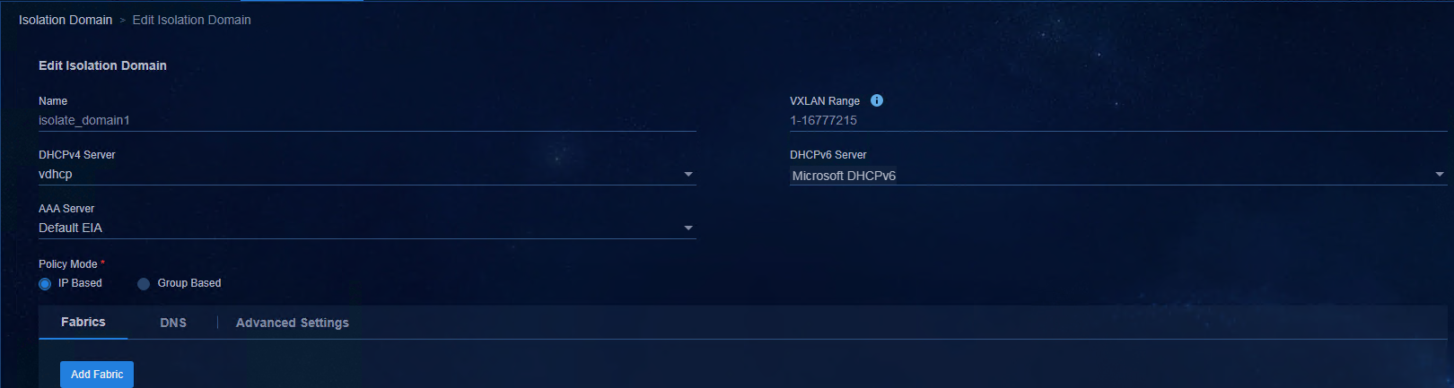
Figure 61 Configuring Microsoft DHCPv6

Figure 62 Binding vDHCP
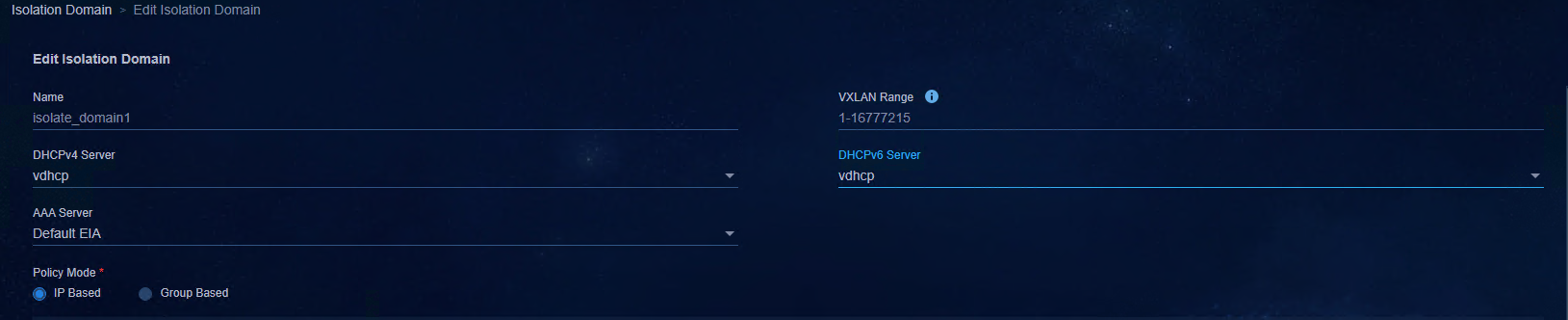
Figure 63 DHCP

Add a Layer 2 network domain
1. Access Automation > Campus
Network > Private Network > Layer 2 Network Domain
page, and click Add to add a Layer 2 network domain, or click the Edit
icon ![]() in the actions column to edit the Layer 2 network domain. This
document takes the editing of a Layer 2 network domain as an example.
in the actions column to edit the Layer 2 network domain. This
document takes the editing of a Layer 2 network domain as an example.
2. For the Layer 2 network domain whose type is normal, configure the IPv6 subnet in the Subnets area at the bottom of the page. When IPv6 Address Allocation is set to SLAAC or Stateless DHCPv6, only global unicast addresses with a prefix length of 64 bits are supported.
Figure 64 Configuring subnets
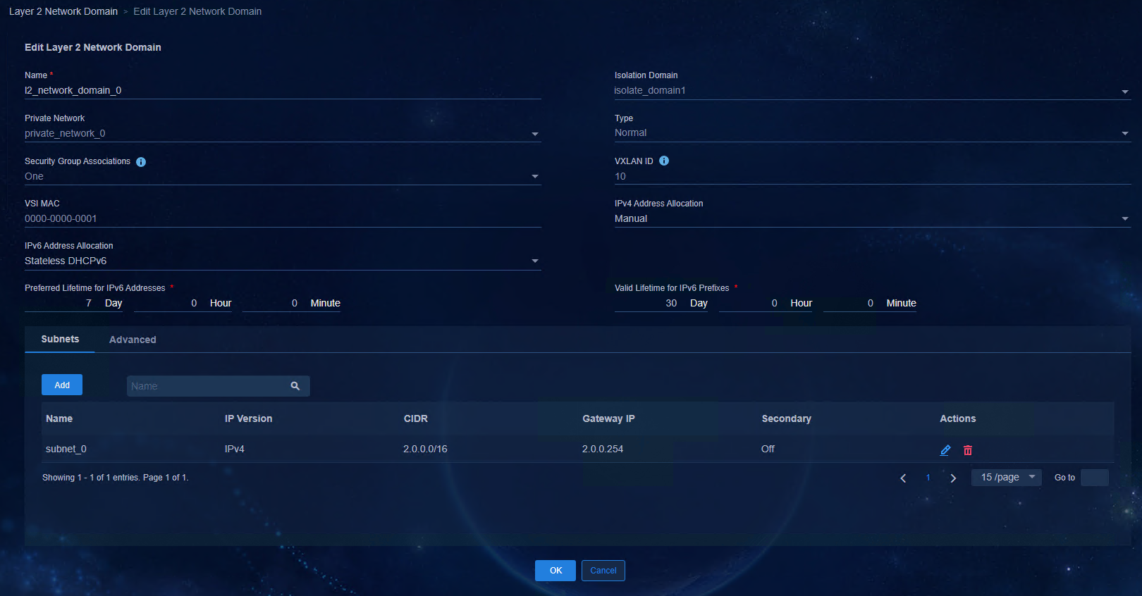
For IPv6 address allocation, the following 4 modes can be selected:
¡ Manual: Manually configure static IPv6 addresses on user terminals.
¡ SLAAC: Short for Stateless Address Autoconfiguration. SLAAC enables an interface to automatically generate an IPv6 global unicast address by using the address prefix in the received RA message and interface ID.
¡ Stateful DHCPv6: The user obtains the IPv6 address via the DHCPv6 server and configures other network parameters based on DHCPv6 server messages. If both M (Managed Address Configuration) flag and O (Other Configuration) flag in the RA message received by the user are set to 1 bit, the DHCPv6 client will automatically enable the stateful DHCPv6 configuration function.
¡ Stateless DHCPv6: The DHCPv6 server assigns other network configuration parameters to clients that already have IPv6 addresses/prefixes, a process known as DHCPv6 stateless configuration. If the M (Managed Address Configuration) flag in the RA message is set to 0 bit, and O (Other Configuration) flag to 1 bit, the DHCPv6 client will automatically enable the stateless DHCPv6 configuration function to obtain other network configuration parameters except addresses/prefixes.
Figure 65 IPv6 address allocation
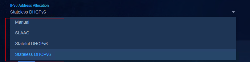
3. Switch to the Advanced tab to enable DHCPv6 Snooping or IPv6 ND Snooping. DHCPv6 snooping ensures that the client obtains IPv6 addresses or IPv6 prefixes from valid servers, and can record the correspondence between IPv6 addresses or IPv6 prefixes of the DHCPv6 client and MAC addresses. IPv6 ND Snooping is a security monitoring technique to prevent ND attacks.
Figure 66 Advanced configuration
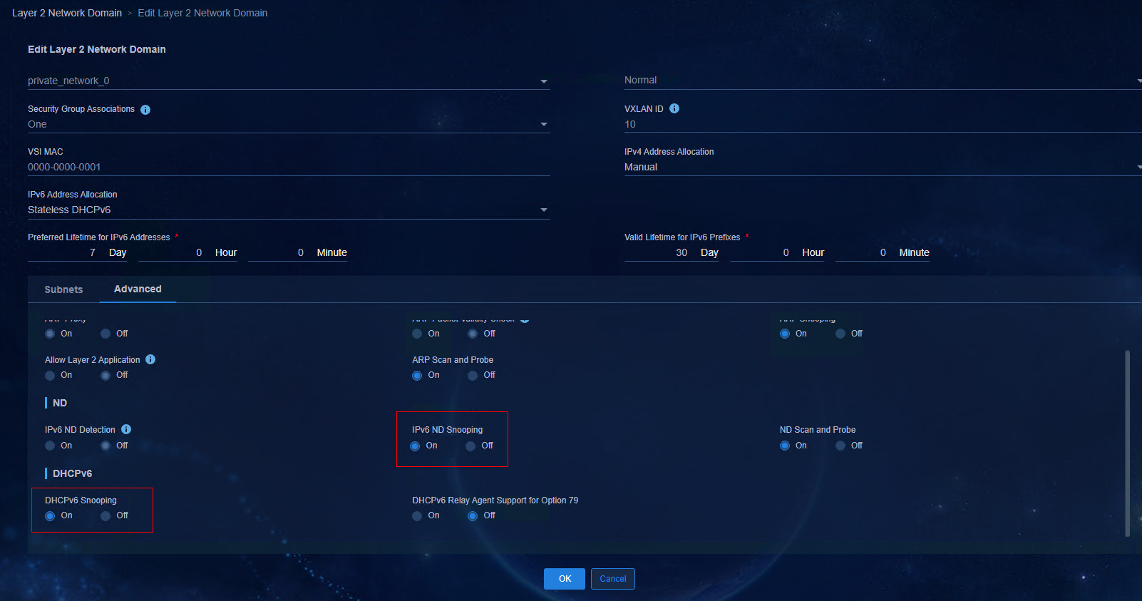
4. After completing the configuration, click OK to save the settings.
Configure the security group
1. Access Automation > Campus
Network > Security Group > User Security Group
page, and click Add to add a security group, or click the Edit
icon ![]() in the actions column. This document takes the editing of the
security group as an example.
in the actions column. This document takes the editing of the
security group as an example.
2. Switch to the Layer 2 Network Domain
Information tab, and click Add. Select Layer 2 Network Domain
in the Optional Layer 2 Network Domain area, click the ![]() icon
to add the Layer 2 network domain to the Selected Layer 2 Network Domain
area, click OK to save the configuration, and the result is shown in the
figure below.
icon
to add the Layer 2 network domain to the Selected Layer 2 Network Domain
area, click OK to save the configuration, and the result is shown in the
figure below.
Figure 67 Adding a Layer 2 network domain

Figure 68 Layer 2 network domain information
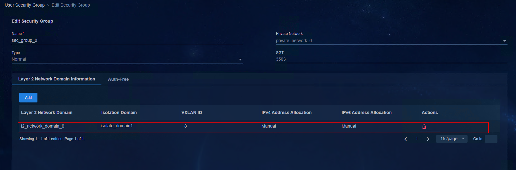
3. After completing the configuration, click OK to save the settings.
Configure IPv6 authentication
To use IPv6 authentication, you can add an H3C EIA V7 (IMC EIA) server on the controller.
1. Access Automation > Network Parameters > AAA page to add an EIA V7 server. For details, see AD-Campus 6.2 Basic Configuration Guide.
Figure 69 Adding an EIA V7 server
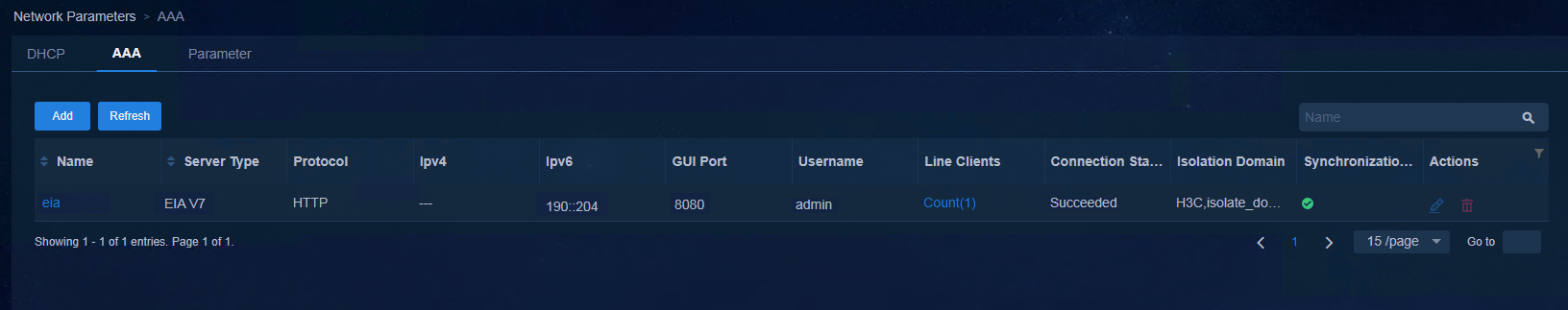
2. Create an AAA policy template.
¡ Access Automation > Device Groups > General Device Groups page, and click Policy Templates. Click Add, and select Device Policy Template from the drop-down list.
¡ Select AAA as template type, and click Add in the Radius Scheme Settings area. On the pop-up page, enter the IPv6 addresses in Primary Auth Server IP and Secondary Auth Server IP.
Figure 70 Adding a Radius scheme
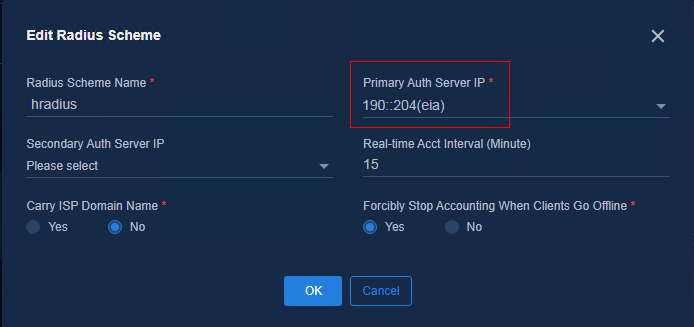
3. After completing the configuration, click OK to save the configuration, and the result is shown in the figure below.
Figure 71 Configuration result
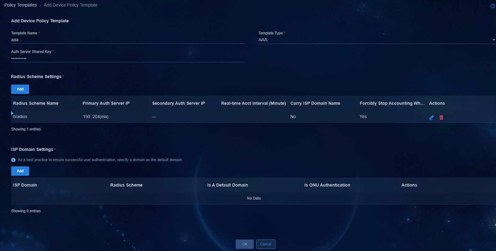
4. Click Add in the ISP Domain Settings area to access the Add ISP Domain page. Select Radius Scheme, set Is A Default Domain to Yes, click OK, and then you will return to the page for adding the device policy template. Click OK to save the template.
Figure 72 Adding an ISP domain
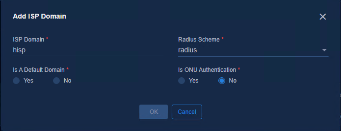
5. Create a MAC/MAC Portal policy template.
¡ Access Automation > Campus Network > Device Groups > General Device Groups page, and click Policy Templates. Click Add, and select Device Policy Template from the drop-down list.
¡ Select MAC/MAC Portal Authentication as the template type, and click Add in the Authentication-Free IPs area. On the pop-up page, enter the IPv6 addresses of the primary and secondary servers.
Figure 73 Authentication exemption information
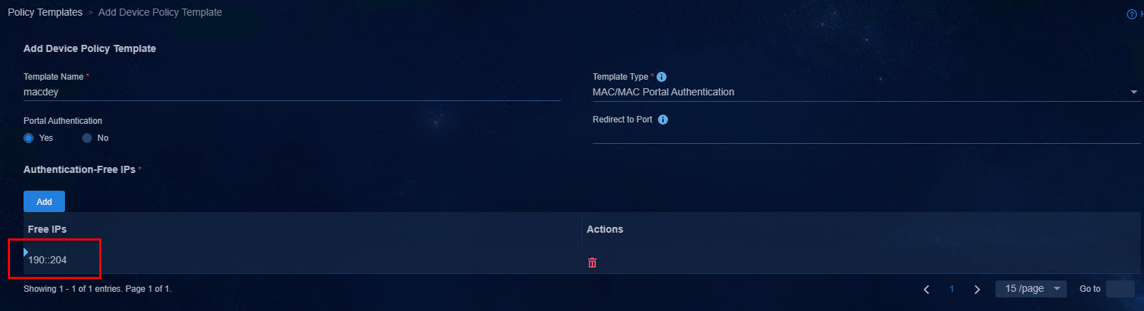
a. After completing the configuration, click OK to save the template.
6. Create an 802.1X policy template.
a. Access Automation > Campus Network > Device Groups > General Device Groups page, and click Policy Templates. Click Add, and select Device Policy Template from the drop-down list.
b. Select 802.1X as the template type and EAP as the authentication method.
Figure 74 Adding an 802.1X device policy template
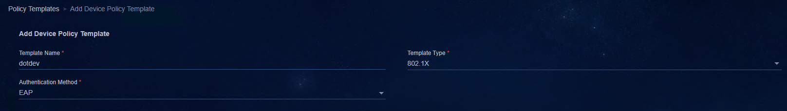
a. After completing the configuration, click OK to save the template.
7. Add the new AAA policy template, 802.1X policy template, and MAC/MAC Portal policy template of IPv6 to its corresponding device group and interface group.
a. Access Automation > Campus
Network > Device Groups > General Device Groups page,
and click the Edit icon ![]() in the actions
column corresponding to the name Leaf Device Group.
in the actions
column corresponding to the name Leaf Device Group.
b. Switch to the Policy tab, and click Add. In the Available Policy Templates area, select AAA as the template type. In the Available AAA Policy area, select the AAA policy template of IPv6 to be added, and click Add to add the template to the Selected Policies area. Repeat the above operations to complete the addition of 802.1X policy template and MAC/MAC Portal policy template. Click OK after the addition of the three policy templates, and then the newly added policies are displayed in the policy list.
Figure 75 Adding policy templates
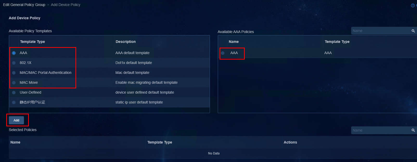
Figure 76 Adding general policy groups
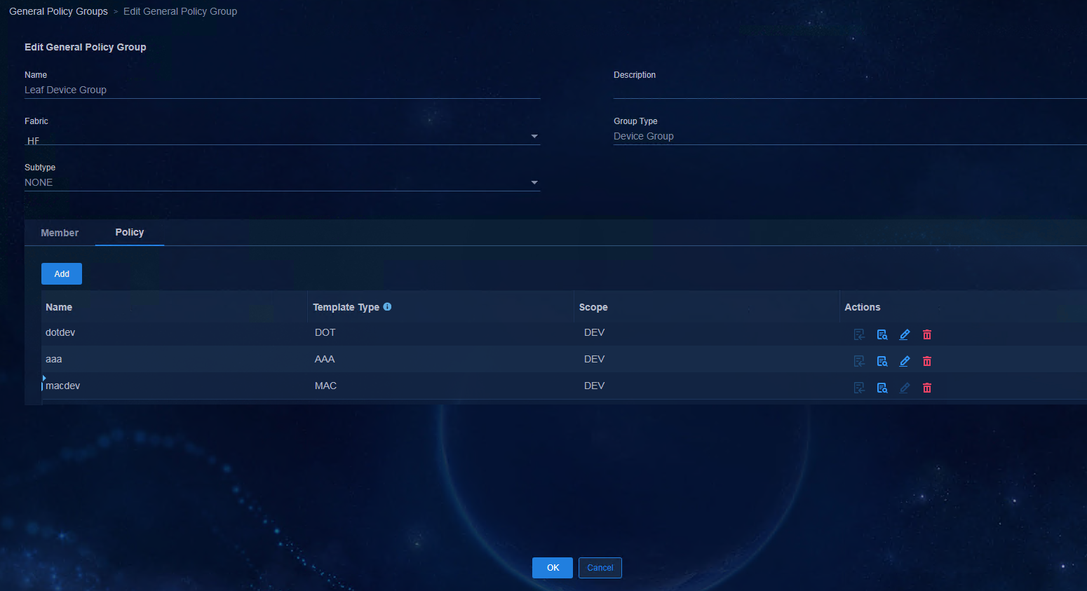
a. After completing the configuration, click OK to save the settings.
8. For users who have IPv6 MAC Portal authentication requirements, the creation of a single-stack IPv6 BYOD Layer 2 network domain and security group are required.
|
|
IMPORTANT: BYOD Layer 2 network domain subnets can only be configured with either IPv4 or IPv6. When a user comes online via MAC Portal authentication, configure an IPv4 subnet in the BYOD Layer 2 network domain for IPv4 EIA authentication and an IPv6 subnet in the BYOD Layer 2 network domain for IPv6 EIA authentication. |
Access Automation > Campus Network > Private Network > Layer 2 Network Domain page, and click Add. Click drop-down arrow of DHCPv6 Server to select the DHCPv6 server to be configured. Switch to the Subnets tab, click Add to configure subnets, and the result is as shown in the figure below.
Figure 77 Adding a Layer 2 network domain
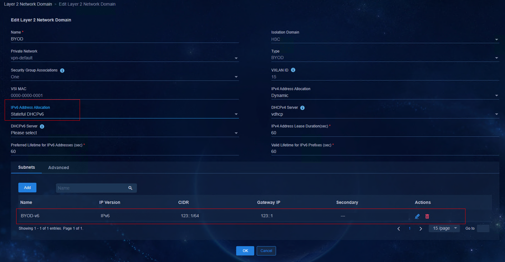
9. On the EIA V7 page, access User > Access Policy Management > Service Parameter Settings > System Settings > System Parameter Settings page to enable IPv6, and the other settings are the same as those for enabling IPv4.
Figure 78 Enabling IPv6 on the EIA V7 page
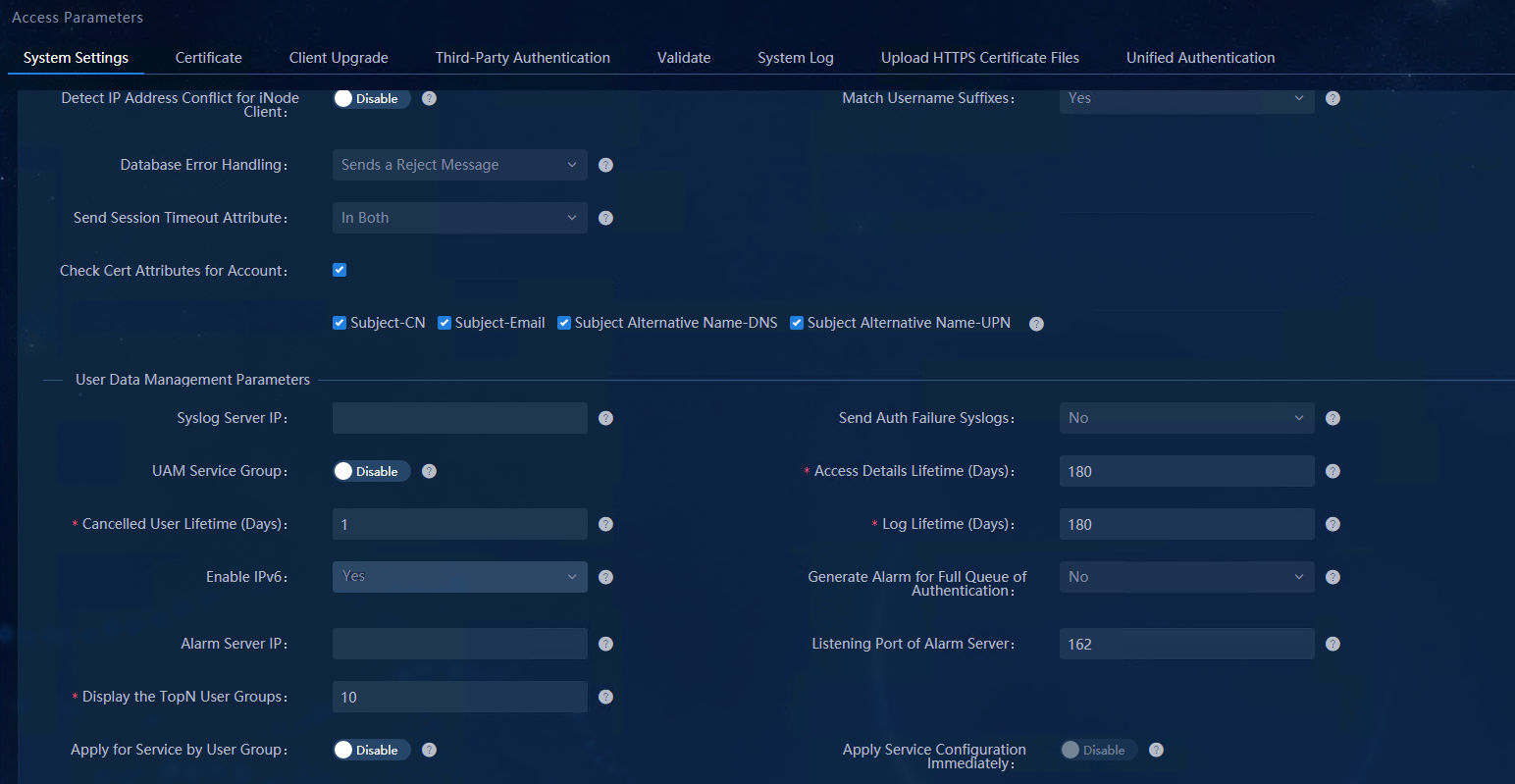
|
|
IMPORTANT: The IPv6 address of EIA V7 needs to be configured during the installation of EIA. If you need to enable the IPv6 function of EIA after completing the configuration of EIA, you can modify the configuration file ( the server-addr file in the path C:\Program File\iMC\common\conf) by changing the IPv6 address segment in the file to 190::204 and restarting the IMC service (modifying the configuration file is not recommended). |
Figure 79 Logging in to the IPv6 address
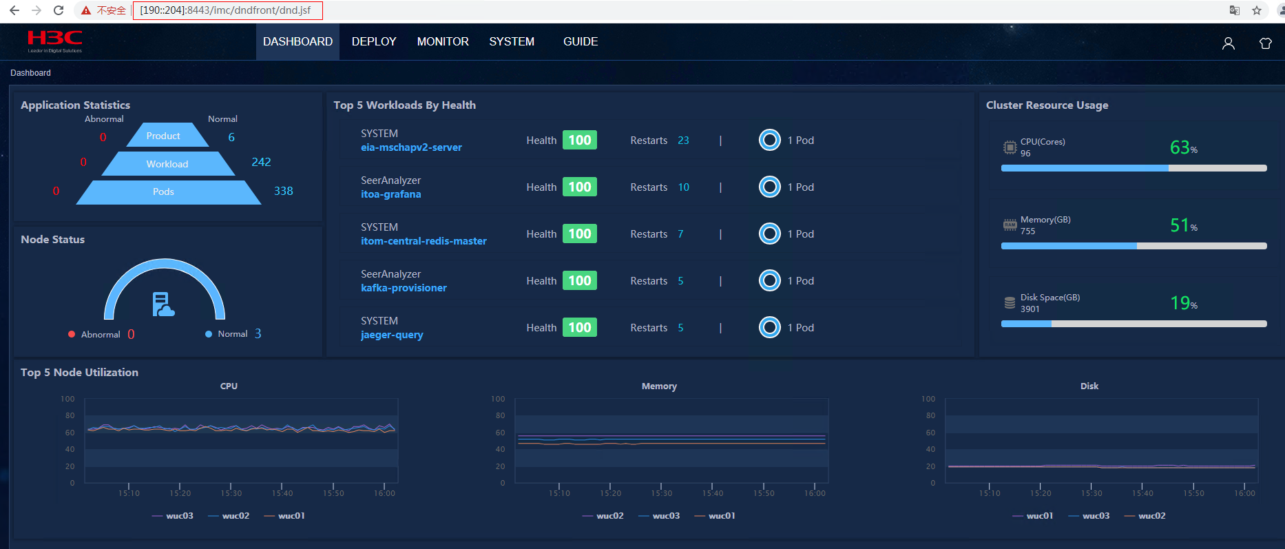
10. After the AAA policy template is bound to the Leaf device group, the controller pushes the access device to EIA V7. On EIA system, access User > Access Service > Access Device Management > Access Device page to view the information about the access device.
Figure 80 Viewing the information about the access device
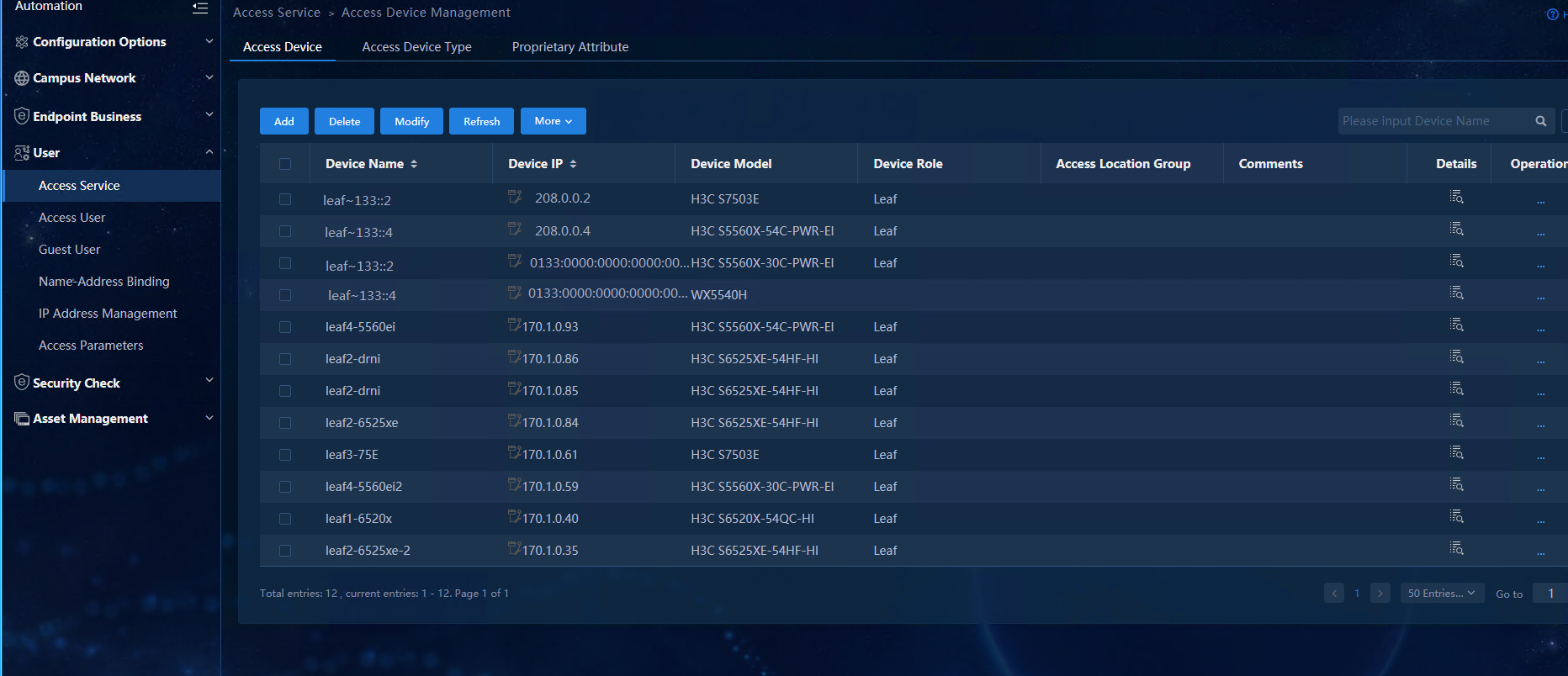
Configure authentication terminals
For a user terminal with a Windows system, when obtaining IPv6 addresses during stateless address autoconfiguration (including stateless DHCPv6 and SLAAC), the user terminal automatically generates two IPv6 addresses: public IPv6 address and temporary IPv6 address.
· Public IPv6 address: Includes the address prefix in the received RA message and a fixed interface ID generated based on the MAC address.
· Temporary IPv6 address: Includes the address prefix in the RA message and a random interface ID generated through MD5.
The IPv6 address with a random interface ID generated during stateless address autoconfiguration decreases network vulnerability. If there is a temporary IPv6 address, the user interacts with external networks via this address.
To enable or disable the temporary IPv6 address, execute the following commands in the Windows terminal command line interface:
netsh interface IPv6 set privacy state=enable
netsh interface IPv6 set privacy state=disable
|
|
CAUTION: When the user comes online via IPv6 MAC Portal authentication, the user needs to open a web page on the user PC in a non-DNS environment and enter any IPv6 address, for example, 23:1::1, so that the user portal can automatically redirect to the default BYOD portal. |
User online
The user online service of IPv6 is the same as that of IPv4, except that IPv6 subnets are used and the user obtains an IPv6 address. For details, see "User authentication and online" in AD-Campus 6.2 Basic Configuration Guide.
O&M monitoring
For details, see AD-Campus 6.2 O&M, Monitoring, and Deployment Guide.
Appendix
Spine device configurations
##
## Please note:The following variable names are used by the internal system,please do not use
## _underlayIntfUp _underlayIntfDown _all_leaf _master_spine
## _master_spine_mac _underlayIPRange
##
##NEW_VERSION
#USERDEF
##Template version
template_version = 5.0
##BACKUP_SERVER
##Local user: Username
_username = h3c
##Local user: Password
_password = campus1234
## User roles
_rbacUserRole = network-admin
##MAC address of the master spine device
_master_spine_mac = 542b-dead-45f8
##MAC address of the master spine device and address range of loopback interfaces
##Format: 1122-3344-5566:10.100.0.0/16, AABB-CCDD-EEFF:10.101.0.0/16
##MAC address and VLAN ID range of the spine device
##Format: 1122-3344-5566:2-100 ,AABB-CCDD-EEFF:101-200
_underlayVLANRange = 542b-dead-45f8:3001-3500
##IP address of the log host
_loghost_ip = 130::195
##is_ipv6_begin_var
##Device is automatically online by ipv6
_is_ipv6 = true
##is_ipv6_end_var
##Out of band
_OOB = False
##SSH enabled
_SSH = True
##Disable automatic IRF setup
_irf_disable = false
##Enabling whitelist filtering (False by default)
_white_list_check = true
##Disabling automatic allocation of an underlay IP (False by default)
_ip_disable = false
##Enabling automatic IRF mode switching
_irf_mode_auto_convert = True
##MAD BFD
_mad_vlan = 100
_mad_ip = 192.168.100.1, 192.168.100.2
##BGP AS number
bgp_as_campus = 100
[H3CS5560X]
driver = 5560X
_switch_mode = 1
[H3CS6520X]
driver = 6520X
_switch_mode = 1
[H3CS125??G-AF]
driver = 125GAF
_tcam_resource = arp
_vxlan_resource = l3gw
_routing_mode_resource = ipv6-128
##
#STATICCFG
#
clock timezone beijing add 08:00:00
#
ip vpn-instance vpn-default
route-distinguisher 1:1
vpn-target 1:1 both
##address_family_evpn_begin
address-family evpn
vpn-target 1:1 import-extcommunity
vpn-target 1:1 export-extcommunity
##address_family_evpn_end
##address_family_ipv6_begin
address-family ipv6
vpn-target 1:1 import-extcommunity
vpn-target 1:1 export-extcommunity
##address_family_ipv6_end
#
lldp global enable
#
interface Vlan-interface1
ip address dhcp-alloc
#
ospfv3 1
non-stop-routing
area 0.0.0.0
#
##loopback0_begin_all
interface LoopBack0
##loopback0_end_all
#
interface $$_underlayIntfDown
ipv6 address auto link-local
ospfv3 1 area 0.0.0.0
ospfv3 network-type p2p
mtu 4094
#
netconf soap https enable
netconf ssh server enable
restful https enable
#
ssh server enable
#
info-center loghost $$_loghost_ip
#
stp mode pvst
stp vlan 1 enable
undo stp vlan 2 to 4094 enable
stp global enable
stp vlan 1 priority 0
#
local-user $$_username
password simple $$_password
service-type http https ssh
authorization-attribute user-role $$_rbacUserRole
#
line vty 0 63
authentication-mode scheme
user-role $$_rbacUserRole
#
bgp $$bgp_as_campus
non-stop-routing
address-family l2vpn evpn
ip vpn-instance vpn-default
##address_family_ipv4_unicast_begin
address-family ipv4 unicast
import-route static
##address_family_ipv4_unicast_end
##address_family_ipv6_unicast_begin
address-family ipv6 unicast
import-route static
##address_family_ipv6_unicast_end
#
l2vpn enable
#
vlan 4094
#
interface Vsi-interface4094
ip binding vpn-instance vpn-default
local-proxy-arp enable
##local-proxy-nd_enable_begin
local-proxy-nd enable
##local-proxy-nd_enable_end
mtu 4094
#
interface Vsi-interface4092
ip binding vpn-instance vpn-default
ip address unnumbered interface Vsi-interface4094
##ipv6_address_auto_link_local_begin
ipv6 address auto link-local
##ipv6_address_auto_link_local_end
l3-vni 4092
description SDN_VRF_VSI_Interface_4092
#
vsi vxlan4094
gateway vsi-interface 4094
vxlan 4094
evpn encapsulation vxlan
mac-advertising disable
nd mac-learning disable
arp mac-learning disable
route-distinguisher auto
vpn-target auto export-extcommunity
vpn-target auto import-extcommunity
##ipv6_dhcp_snooping_trust_tunnel_begin
ipv6 dhcp snooping trust tunnel
##ipv6_dhcp_snooping_trust_tunnel_end
loopback-detection action block
loopback-detection enable vlan 4094
#
vxlan tunnel mac-learning disable
vxlan tunnel arp-learning disable
vxlan tunnel nd-learning disable
#
vcf-fabric topology enable
#
vxlan default-decapsulation source interface LoopBack 0
#
##ipv6_static_route_begin_all
ipv6 route-static vpn vpn-default 130:0:0:0:0:0:0:0 64 133:0:0:0:0:0:0:1
ipv6 route-static vpn vpn-default 190:0:0:0:0:0:0:0 64 133:0:0:0:0:0:0:1
ipv6 route-static 130:0:0:0:0:0:0:0 64 132:0:0:0:0:0:0:1
ipv6 route-static 190:0:0:0:0:0:0:0 64 132:0:0:0:0:0:0:1
#
##ipv6_static_route_end_all
#
snmp-agent
snmp-agent community read public
snmp-agent community write private
snmp-agent sys-info version all
snmp-agent packet max-size 4096
#
telnet server enable
#
netconf soap https enable
netconf soap http enable
local-user h3c
password simple campus1234
service-type telnet ssh http https
authorization-attribute user-role network-admin
#
Leaf device configurations
##
## Please note:The following variable names are used by the internal system,please do not use
## _underlayIntfUp _underlayIntfDown _all_leaf _master_spine _backup_spine
## _master_spine_mac
##
##NEW_VERSION
#USERDEF
##Template version
template_version = 5.0
##Local user: Username
_username = h3c
##Local user: Password
_password = campus1234
## User roles
_rbacUserRole = network-admin
##master_leaf_mac_begin_var
##MAC address of the master leaf device
_master_leaf_mac =${master_leaf_mac}
##master_leaf_mac_end_var
##IP address of the log host
_loghost_ip = 130::195
##is_ipv6_begin_var
##Device is automatically online by ipv6
_is_ipv6 = true
##is_ipv6_end_var
##Out of band
_OOB = False
##Supporting aggregation (True by default)
_lagg_enable = True
##Enforcing aggregation
_lagg_force = True
##Do not delete aggregation group
_lagg_fake_delete = True
##SSH enabled
_SSH = True
##Disable automatic IRF setup
_irf_disable = false
##Enabling whitelist filtering (False by default)
_white_list_check = true
##Enabling automatic IRF mode switching
## Enable OLT interface
_olt = true
## auto IRF mode convert
_irf_mode_auto_convert = True
##MAD BFD
_mad_vlan = 100
_mad_ip = 192.168.100.1, 192.168.100.2
##BGP AS number
bgp_as_campus = 100
##Disable lldp function when MAD BFD
_mad_undo_lldp=True
[H3CS5560X]
driver = 5560X
_switch_mode = 1
[H3CS6520X]
driver = 6520X
_switch_mode = 1
[H3CS125??G-AF]
driver = 125GAF
_tcam_resource = mix
_vxlan_resource = l3gw
_routing_mode_resource = ipv6-128
[UNISS5600X]
driver = 5560X
_switch_mode = 1
[UNISS6600X]
driver = 6520X
_switch_mode = 1
##
#STATICCFG
#
clock timezone beijing add 08:00:00
#
ip vpn-instance vpn-default
route-distinguisher 1:1
vpn-target 1:1 both
##address_family_evpn_begin
address-family evpn
vpn-target 1:1 import-extcommunity
vpn-target 1:1 export-extcommunity
##address_family_evpn_end
##address_family_ipv6_begin
address-family ipv6
vpn-target 1:1 import-extcommunity
vpn-target 1:1 export-extcommunity
##address_family_ipv6_end
#
lldp global enable
#
dhcp snooping enable vlan 2 to 4094
#
interface Vlan-interface1
ip address dhcp-alloc
#
ospfv3 1
non-stop-routing
area 0.0.0.0
#
##loopback0_begin_all
interface LoopBack0
##loopback0_end_all
#
stp mode pvst
stp vlan 1 enable
undo stp vlan 2 to 4094 enable
stp global enable
stp vlan 1 priority 8192
#
netconf soap https enable
netconf ssh server enable
restful https enable
#
ssh server enable
#
info-center loghost $$_loghost_ip
#
local-user $$_username
password simple $$_password
service-type http https ssh
authorization-attribute user-role $$_rbacUserRole
#
line vty 0 63
authentication-mode scheme
user-role $$_rbacUserRole
#
bgp $$bgp_as_campus
non-stop-routing
address-family l2vpn evpn
ip vpn-instance vpn-default
##address_family_ipv4_unicast_begin
address-family ipv4 unicast
##address_family_ipv4_unicast_end
##address_family_ipv6_unicast_begin
address-family ipv6 unicast
##address_family_ipv6_unicast_end
#
interface $$_underlayIntfUp
ipv6 address auto link-local
ospfv3 1 area 0.0.0.0
ospfv3 network-type p2p
mtu 4094
#
interface $$_underlayIntfDown
port link-type trunk
port trunk permit vlan all
undo port trunk permit vlan $$_mad_vlan
stp tc-restriction
service-instance 4094
encapsulation s-vid 4094
xconnect vsi vxlan4094
#
interface $$_underlayIntfGe
poe enable
#
interface $$_underlayIntfONU
port link-type trunk
port trunk permit vlan all
undo port trunk permit vlan $$_mad_vlan
#
interface $$_underlayIntfRONU
port link-type trunk
port trunk permit vlan all
undo port trunk permit vlan $$_mad_vlan
#
l2vpn enable
#
vlan 4094
#
interface Vsi-interface4094
ip binding vpn-instance vpn-default
local-proxy-arp enable
##local-proxy-nd_enable_begin
local-proxy-nd enable
##local-proxy-nd_enable_end
arp proxy-send enable
mtu 4094
#
interface Vsi-interface4092
ip binding vpn-instance vpn-default
ip address unnumbered interface Vsi-interface4094
##ipv6_address_auto_link_local_begin
ipv6 address auto link-local
##ipv6_address_auto_link_local_end
l3-vni 4092
description SDN_VRF_VSI_Interface_4092
#
vsi vxlan4094
gateway vsi-interface 4094
vxlan 4094
evpn encapsulation vxlan
mac-advertising disable
nd mac-learning disable
arp mac-learning disable
route-distinguisher auto
vpn-target auto export-extcommunity
vpn-target auto import-extcommunity
##ipv6_dhcp_snooping_trust_tunnel_begin
ipv6 dhcp snooping trust tunnel
##ipv6_dhcp_snooping_trust_tunnel_end
dhcp snooping trust tunnel
loopback-detection action block
loopback-detection enable vlan 4094
#
ip verify source exclude vlan 1
ip verify source exclude vlan 4094
#
vxlan tunnel mac-learning disable
vxlan tunnel arp-learning disable
vxlan tunnel nd-learning disable
#
vcf-fabric topology enable
#
vxlan default-decapsulation source interface LoopBack 0
#
##ipv6_static_route_begin_all
ipv6 route-static vpn vpn-default 130:0:0:0:0:0:0:0 64 133:0:0:0:0:0:0:1
ipv6 route-static vpn vpn-default 190:0:0:0:0:0:0:0 64 133:0:0:0:0:0:0:1
ipv6 route-static 130:0:0:0:0:0:0:0 64 132:0:0:0:0:0:0:1
ipv6 route-static 190:0:0:0:0:0:0:0 64 132:0:0:0:0:0:0:1
#
##ipv6_static_route_end_all
#
##ipv6_dhcp_snooping_enable_begin
ipv6 dhcp snooping enable vlan 2 to 4094
#
##ipv6_dhcp_snooping_enable_end
snmp-agent
snmp-agent community read public
snmp-agent community write private
snmp-agent sys-info version all
snmp-agent packet max-size 4096
#
telnet server enable
#
netconf soap https enable
netconf soap http enable
local-user h3c
password simple campus1234
service-type telnet ssh http https
authorization-attribute user-role network-admin
#
Access device configurations
##
## Please note:The following variable names are used by the internal system,please do not use
## _underlayIntfUp _underlayIntfDown _all_leaf _master_spine _backup_spine
## _master_spine_mac
##
#USERDEF
##Template version
template_version = 5.0
## User roles
_rbacUserRole = network-admin
##IP address of the log host
_loghost_ip = 130::195
##is_ipv6_begin_var
##Device is automatically online by ipv6
_is_ipv6 = true
##is_ipv6_end_var
##Out of band
_OOB = False
##Supporting aggregation (True by default)
_lagg_enable = True
##Enforcing aggregation
_lagg_force = True
##Do not delete aggregation group
_lagg_fake_delete = True
##SSH enabled
_SSH = True
##Disable automatic IRF setup
_irf_disable = false
##Enabling whitelist matching (False by default)
_white_list_check = true
##Disable lldp function when MAD BFD
_mad_undo_lldp=True
#STATICCFG
#
clock timezone beijing add 08:00:00
#
lldp global enable
#
stp global enable
#
netconf soap https enable
netconf ssh server enable
restful https enable
#
interface Vlan-interface1
ip address dhcp-alloc
#
ssh server enable
#
info-center loghost $$_loghost_ip
#
line vty 0 63
authentication-mode scheme
user-role $$_rbacUserRole
#
interface $$_underlayIntfUp
port link-type trunk
port trunk permit vlan all
port link-aggregation group auto 1
#
interface $$_underlayIntfDown
port link-type trunk
port trunk pvid vlan 4093
port trunk permit vlan all
#
interface $$_underlayIntfGe
poe enable
#
vlan 4093
#
vlan 4094
#
interface Vlan-interface4094
#
#
vcf-fabric topology enable
#
#
##ipv6_static_route_begin_all
ipv6 route-static 130:0:0:0:0:0:0:0 64 133:0:0:0:0:0:0:1
ipv6 route-static 190:0:0:0:0:0:0:0 64 133:0:0:0:0:0:0:1
ipv6 route-static 130:0:0:0:0:0:0:0 64 132:0:0:0:0:0:0:1
ipv6 route-static 190:0:0:0:0:0:0:0 64 132:0:0:0:0:0:0:1
#
##ipv6_static_route_end_all
#
snmp-agent
snmp-agent community read public
snmp-agent community write private
snmp-agent sys-info version all
snmp-agent packet max-size 4096
#
telnet server enable
#
netconf soap https enable
netconf soap http enable
local-user h3c
password simple campus1234
service-type telnet ssh http https
authorization-attribute user-role network-admin
#
