
- Released At: 13-09-2023
- Page Views:
- Downloads:
- Table of Contents
- Related Documents
-
|
|
|
AD-Campus 6.2 |
|
|
|
|
Document version: 5W100-20230221
Copyright © 2023 New H3C Technologies Co., Ltd. All rights reserved.
No part of this manual may be reproduced or transmitted in any form or by any means without prior written consent of New H3C Technologies Co., Ltd.
Except for the trademarks of New H3C Technologies Co., Ltd., any trademarks that may be mentioned in this document are the property of their respective owners.
This document provides generic technical information, some of which might not be applicable to your products.
The information in this document is subject to change without notice.
Contents
About semi-automated deployment
Configure semi-automated deployment (standard network)
Plan network resources and IP addresses
Incorporate spine devices and leaf devices
Configure access automation template
Enable VCF fabric topology discovery and configure AC interfaces for leaf devices
Onboard a single access device
Restore the factory-default configuration
Restart the access device with the factory-default configuration
Verify the deployment result on the access device
Verify the access deployment on the controller
Automatic leaf-access link aggregation
Manually configur link aggregation and AC settings on the leaf device side
Automatic link aggregation on the access device side
Deploy multiple tiers of access devices
Restart a lower-tier access device with the factory-default configuration
Configure semi-automated deployment (L3 network-traversed spine-leaf connection)
Map VLAN 1 to VXLAN 1 on the uplink ports of the spine tier
Map VLAN 1 to VXLAN 1 on the downlink ports of the leaf tier
Automated deployment of access devices
Configure the DHCP relay gateway
Configure ACs and the wireless management network
Overview
About semi-automated deployment
The semi-automated campus role deployment consists of the following:
· Manual configuration of spine devices and leaf devices, and manual incorporation of these devices on the controller.
· Automated deployment of access devices.
Restrictions and guidelines
For the restrictions and guidelines on automated deployment, see AD-Campus 6.2 Automation Configuration Guide or AD-Campus 6.2 Optimized Automation Configuration Guide. This document only introduces the restrictions and guidelines on semi-automated deployment.
· Before implementing automated access device deployment, you must perform the following tasks on each leaf device:
a. Manually enable VCF fabric topology discovery.
b. Manually configure the access-attached downlink port as an AC interface.
· The leaf-attached uplink ports on each access device supports automatic aggregation. However, you need to manually configure link aggregation for the access-attached downlink ports on each leaf device, and then configure each aggregate interface as an AC interface.
· Before automated device deployment, use the restore factory-default command to restore the factory-default configuration for the device.
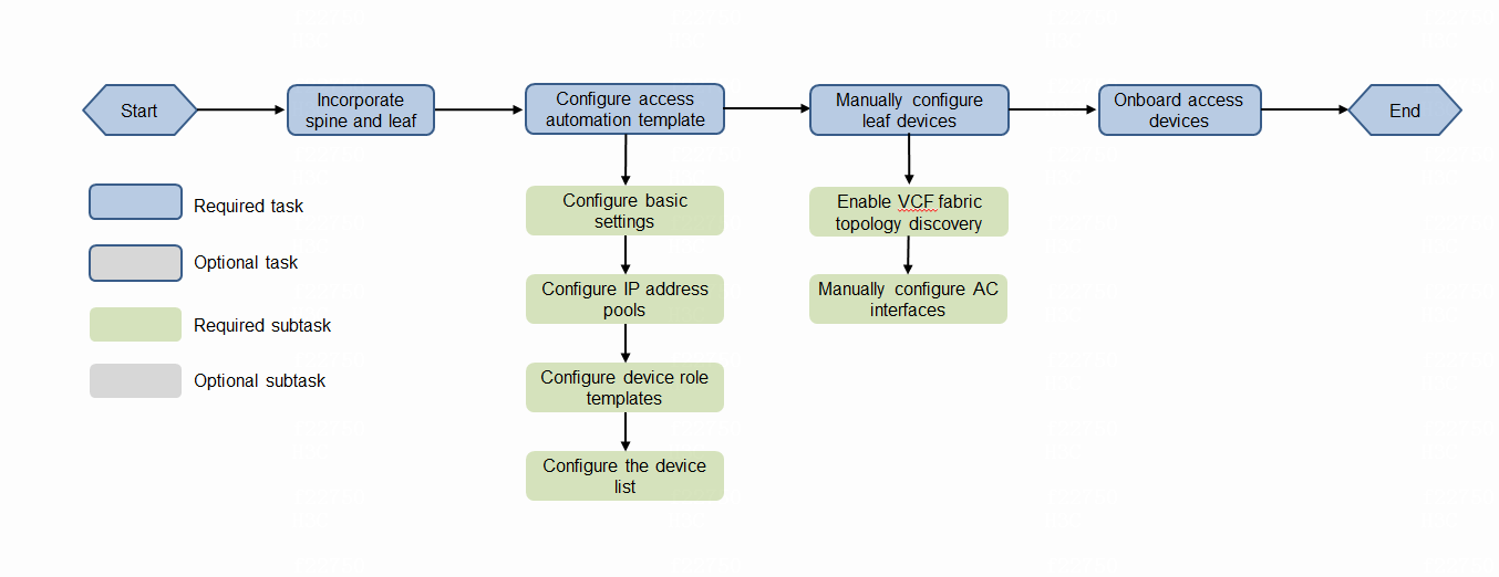
Deployment workflow
Figure 1 shows the deployment workflow of semi-automated network deployment:
Figure 1 Workflow of semi-automated network deployment
Configure semi-automated deployment (standard network)
For more information about the architecture of a standard network, see AD-Campus 6.2 Automation Configuration Guide or AD-Campus 6.2 Optimized Automation Configuration Guide.
Plan network resources and IP addresses
Before a semi-automated network deployment, plan the network architecture and resources properly. Figure 2 shows the IP address scheme used in this document.
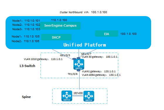
Table 1 shows the addressing scheme used in this document.
|
Item |
Address |
Description |
|
VLAN 1010 subnet (gateway IP) |
110.1.0.0/24(110.1.0.1) |
Subnet for the SeerEngine-Campus controller and vDHCP, used for the communication between the PC and the controller. (configure this subnet when SeerEngine-Campus uses an independent NIC) |
|
SeerEngine-Campus cluster IP |
110.1.0.100 |
Address of the SeerEngine-Campus controller cluster. |
|
VLAN 1 subnet (gateway IP) |
120.1.0.0/24 (120.1.0.1) |
Network for VLAN 1, used for automated onboarding. |
|
VLAN 4094 subnet (gateway IP) |
130.1.0.0/24(130.1.0.1) |
Network for VLAN 4094, used for communication between the controller and the devices. |
|
VLAN 4093 subnet (gateway IP) |
30.0.3.0/24(30.0.3.89) |
VLAN-interface 4093 is the Layer 3 interface for communication with the AP. |
Incorporate spine devices and leaf devices
Manually configure spine devices and leaf devices, and then incorporate them on the controller. For more information about this task, see AD-Campus 6.2 Basic Configuration Guide.
Configure access automation template
Configure the automation template for access devices on the controller. For more information about this task, see AD-Campus 6.2 Automation Configuration Guide or AD-Campus 6.2 Optimized Automation Configuration Guide, depending on the automation method.
Enable VCF fabric topology discovery and configure AC interfaces for leaf devices
Before implementing automated access device deployment, you must perform the following tasks on the leaf device:
1. Manually enable VCF fabric topology discovery. This feature sends leaf device information to the access devices through LLDP. If you do not enable this feature, the access devices cannot find the link to the leaf device.
#
vcf-fabric topology enable
#
2. Manually configure the access-attached downlink port as an AC interface.
#
interface Ten-GigabitEthernet1/3/0/1
port link-mode bridge
port link-type trunk
port trunk permit vlan all
service-instance 4094
encapsulation s-vid 4094
xconnect vsi vxlan4094
#
3. (Optional.) If the leaf device is in a DR system, add the following configuration:
#
vsi vxlan4094
gateway vsi-interface 4094
vxlan 4094
evpn encapsulation vxlan
mac-advertising disable
nd mac-learning disable
arp mac-learning disable
route-distinguisher auto
vpn-target auto export-extcommunity
vpn-target auto import-extcommunity
dhcp snooping trust tunnel
loopback-detection action block
loopback-detection enable vlan 4094
#
Onboard a single access device
Restore the factory-default configuration
Before onboarding a single access device, you must restore its factory-default configuration.
<Sysname> restore factory-default
This command will restore the system to the factory default configuration and clear the operation data. Continue [Y/N]:y
Restoring the factory default configuration. This process might take a few minutes. Please wait..........................................................................................................Done.
Please reboot the system to place the factory default configuration into effect.
Restart the access device with the factory-default configuration
Restart the access device after you restore its factory-default configuration.
On startup, the access device automatically obtains an IP address for VLAN-interface 1 and the access device configuration template. The following is the sample output:
Automatic configuration attempt: 1.
Interface used: Vlan-interface1.
Enable DHCP client on Vlan-interface1.
Obtained an IP address for Vlan-interface1: 120.1.0.7.
Obtained configuration file name HJYQ.template and TFTP server name 110.1.0.100.
Resolved the TFTP server name to 110.1.0.100.
INFO: Not found tag file device_tag.csv.
Successfully downloaded file HJYQ_access.template.
Executing the configuration file. Please wait...
Automatic configuration successfully completed.
Line aux0 is available.
Press ENTER to get started.
The access device automatically configures itself based on the obtained access device template (for example, HJYQ_access.template).
Each downlink port on the device will be assigned a unique PVID. If the access device is PoE capable, PoE will be enabled on all PoE-capable ports. If an AP is attached to a port, VLAN 4093 will be deployed and set as the PVID of that port.
In user view, you can use the dir command to identify the template file named HJYQ_access.template, and use the more HJYQ_access.template command to view settings in the template.
Verify the deployment result on the access device
# After the access device completes automatic configuration, verify that the access device has obtained IP addresses for VLAN-interface 1 and VLAN-interface 4094.
#
[Access31]display int brief | in UP
InLoop0 UP UP(s) --
NULL0 UP UP(s) --
Vlan1 UP UP 120.1.0.7
Vlan4094 UP UP 130.1.0.6
XGE1/0/25 UP 10G(a)
#
# Verify that the uplink port on the access device is configured as a trunk port and permits all VLANs to pass through.
#
interface Ten-GigabitEthernet1/0/25
port link-type trunk
port trunk permit vlan all
#
# Verify the settings on interfaces. In the following sample output, the interface is PoE enabled and assigned PVID 4093 because an AP is attached to it.
#
interface GigabitEthernet5/0/5
port link-type trunk
port trunk permit vlan all
port trunk pvid vlan 4093
poe enable
#
Verify the access deployment on the controller
View devices on the controller.
# Verify that the access device has been incorporated as a managed device. Its management IP address has changed from the IP address of VLAN-interface 1 to that of VLAN-interface 4094.
Figure 3 Access device

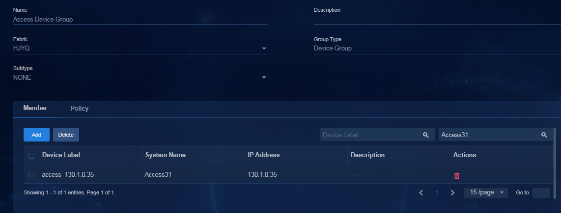
# Verify that the access device has been assigned to the access device group.
Figure 4 Access device group
Onboard an access IRF fabric
1. Connect the two devices (Access 1 and Access 2) to the leaf tier.
2. Connect the two devices.
3. Clear the configuration of the two devices and restart them simultaneously.
Access 1 automatically establishes an IRF fabric with Access 2 when the following conditions exist:
¡ Access 1 detects that it has a 10 GE port connected to Access 2.
¡ Access 1 and Access 2 have the same role.
4. Verify that the IRF fabric has been established.
<access1>dis irf
MemberID Role Priority CPU-Mac Description
*+1 Master 2 00e0-fc0f-8c02 ---
5 Standby 1 00e0-fc0f-8c06 ---
--------------------------------------------------
* indicates the device is the master.
+ indicates the device through which the user logs in.
The bridge MAC of the IRF is: 50da-00ea-d9f8
Auto upgrade : yes
Mac persistent : always
Domain ID : 0
|
|
NOTE: This solution does not support automated configuration of BFD MAD for IRF fabrics at the access tier. When you manually configure BFD MAD for an access IRF fabric, configure the undo port trunk permit vlan 100 command on the following ports: · Uplink ports of the access devices in the IRF fabric. · Downlink ports on the leaf devices attached to the IRF fabric. |
5. Manually configure BFD MAD.
a. Ensure that the physical interfaces for BFD MAD are down, and then configure BFD MAD.
#
vlan 100 //This VLAN is used for BFD MAD only.
#
#
interface GigabitEthernet1/0/20
port link-type trunk
undo port trunk permit vlan 1
port trunk permit vlan 100
undo stp enable
stp edged-port //If this command was not included, audit difference would be found with the controller.
undo lldp enable
#
#
interface GigabitEthernet5/0/20
port link-type trunk
undo port trunk permit vlan 1
port trunk permit vlan 100
undo stp enable
stp edged-port //If this command was not included, audit difference would be found with the controller.
undo lldp enable
#
#
interface Vlan-interface100
mad bfd enable
mad ip address 192.168.100.1 255.255.255.0 member 1
mad ip address 192.168.100.5 255.255.255.0 member 5
#
b. Connect the physical interfaces for BFD MAD, and verify that BFD MAD operates correctly.
[5130s-hi-down]disp mad verbose
Multi-active recovery state: No
Excluded ports (user-configured):
Excluded ports (system-configured):
IRF physical interfaces:
Ten-GigabitEthernet1/0/25
Ten-GigabitEthernet5/0/25
BFD MAD interfaces:
Bridge-Aggregation1022
Bridge-Aggregation1024
GigabitEthernet1/0/2
GigabitEthernet1/0/20
GigabitEthernet5/0/1
GigabitEthernet5/0/20
Ten-GigabitEthernet1/0/26
Ten-GigabitEthernet5/0/26
Vlan-interface100
MAD ARP disabled.
MAD ND disabled.
MAD LACP disabled.
MAD BFD enabled interface: Vlan-interface99
MAD status : Normal
Member ID MAD IP address Neighbor MAD status
1 192.168.100.1/24 5 Normal
5 192.168.100.5/24 1 Normal
Automatic leaf-access link aggregation
|
|
IMPORTANT: · Each link aggregation can have only two physical links. · On the leaf side, you need to manually configure link aggregation and AC settings. |
Manually configur link aggregation and AC settings on the leaf device side
#
interface Ten-GigabitEthernet5/0/28
port link-mode bridge
port link-type trunk
port trunk permit vlan 1 101 to 3000 4094
port trunk pvid vlan 4094
port link-aggregation group 1
#
#
interface Ten-GigabitEthernet1/0/28
port link-mode bridge
port link-type trunk
port trunk permit vlan 1 101 to 3000 4094
port trunk pvid vlan 4094
port link-aggregation group 1
#
#
interface Bridge-Aggregation1
port link-type trunk
port trunk permit vlan 1 101 to 3000 4094
link-aggregation mode dynamic
#
service-instance 4094
encapsulation s-vid 4094
xconnect vsi vxlan4094
#
Automatic link aggregation on the access device side
<access1> dis link-aggregation verbose
Loadsharing Type: Shar -- Loadsharing, NonS -- Non-Loadsharing
Port Status: S -- Selected, U -- Unselected, I -- Individual
Port: A -- Auto port, M -- Management port, R -- Reference port
Flags: A -- LACP_Activity, B -- LACP_Timeout, C -- Aggregation,
D -- Synchronization, E -- Collecting, F -- Distributing,
G -- Defaulted, H -- Expired
Aggregate Interface: Bridge-Aggregation1024
Creation Mode: Manual
Aggregation Mode: Dynamic
Loadsharing Type: Shar
Management VLANs: None
System ID: 0x8000, 487a-da2f-717a
Local:
Port Status Priority Index Oper-Key Flag
GE1/0/25 S 32768 1 1 {ACDEF}
GE1/0/31 S 32768 2 1 {ACDEF}
Remote:
Actor Priority Index Oper-Key SystemID Flag
GE1/0/25 32768 32770 40001 0xa , 346b-5b89-0617 {ACDEF}
GE1/0/31(R) 32768 16386 40001 0xa , 346b-5b89-0617 {ACDEF}
Deploy multiple tiers of access devices
If you are deploying multiple tiers of access devices, use GE ports to cascade them.
The solution supports up to three access tiers, with access tier 1 directly connected to the leaf tier, access tier 2 connected to access tier 1, and so on.
|
|
NOTE: · When a tier-1 device is deployed, its downlink ports are assigned PVIDs in the range of 101 to 3000. When a downlink port on the device comes up, its PVID changes to 1 if the port connects to an H3C switch. This change ensures automatic deployment of the lower-tier access device. If the tier-1 device is not an H3C device, you must manually change the PVID of the downlink port to 1. · A lower-tier access device can have a maximum of two physical links aggregated to connect to its higher-tier access device. |
Restart a lower-tier access device with the factory-default configuration
On startup, the access device (for example, a tier-2 access device) automatically configures itself. The following sample output shows the automated onboarding process:
Automatic configuration attempt: 2.
Interface used: Vlan-interface1.
Enable DHCP client on Vlan-interface1.
Set DHCP client identifier: 487ada92a6cb-VLAN0001
Obtained an IP address for Vlan-interface1: 120.1.0.12.
Obtained configuration file name HJYQ.template and TFTP server name 110.1.0.100 //TFTP server's address on the controller.
Resolved the TFTP server name to 110.1.0.100.
INFO: Get device tag file device_tag.csv success.
INFO: Read role access from tag file.
Successfully downloaded file HJYQ_access.template. //Name of the access template on the controller.
Executing the configuration file. Please wait...
INFO: Read location access22 from tag file.
Automatic configuration successfully completed.
Line aux4 is available.
Press ENTER to get started.
Verify the deployment result
# Verify that VLAN-interface 1 and VLAN-interface 4094 have each obtained an IP address:
[Access32]dis int brief
Brief information on interfaces in route mode:
Link: ADM - administratively down; Stby - standby
Protocol: (s) - spoofing
Interface Link Protocol Primary IP Description
InLoop0 UP UP(s) --
NULL0 UP UP(s) --
Vlan1 UP UP 120.1.0.12
Vlan4094 UP UP 130.1.0.10
# On the controller, verify that the tier-2 access device has been incorporated.
Figure 5 Access device

The tier-2 access device can be automatically added to the access device group.
Figure 6 Access device group

Configure semi-automated deployment (L3 network-traversed spine-leaf connection)
Network plan
Figure 7 L3 network-traversed spine-leaf connection
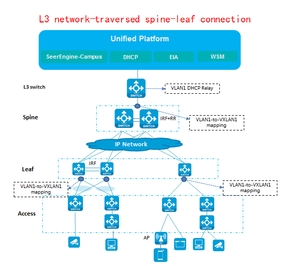
Analysis
The intermediate layer between the spine tier and the leaf tier might be ISP MPLS. By default, the spine tier and the leaf tier cannot transparently transmit VLAN 1 packets. To resolve this issue, map VLAN 1 to VXLAN1 on the downlink ports of the leaf tier and on the uplink ports of the spine tier. The two tier can pass through VLAN 1 packets to each other over Layer 2 VXLAN1.
Map VLAN 1 to VXLAN 1 on the uplink ports of the spine tier
[7504E-XS]dis cu int te 2/3/1
#
interface Ten-GigabitEthernet2/3/1
port link-mode bridge
description To L3Switch
port link-type trunk
port trunk permit vlan 1 4094
#
service-instance 1 // To avoid configuration audit or sync errors, make sure you reserve incremental configuration.
encapsulation untagged
xconnect vsi vxlan1
#
service-instance 4094
encapsulation s-vid 4094
xconnect vsi vxlan4094
#
return
#
vsi vxlan1
gateway vsi-interface 1
vxlan 1
evpn encapsulation vxlan
mac-advertising disable
arp mac-learning disable
route-distinguisher auto
vpn-target auto export-extcommunity
vpn-target auto import-extcommunity
dhcp snooping trust tunnel
#
Map VLAN 1 to VXLAN 1 on the downlink ports of the leaf tier
[7500E]dis cu int te 1/3/0/25
#
interface Ten-GigabitEthernet1/3/0/25
port link-mode bridge
port link-type trunk
port trunk permit vlan all
#
service-instance 1 // To avoid configuration audit or sync errors, make sure you select Reserve Extra Configuration.
encapsulation untagged
xconnect vsi vxlan1
#
service-instance 4094
encapsulation s-vid 4094
xconnect vsi vxlan4094
#
return
#
vsi vxlan1
gateway vsi-interface 1
vxlan 1
evpn encapsulation vxlan
mac-advertising disable
arp mac-learning disable
route-distinguisher auto
vpn-target auto export-extcommunity
vpn-target auto import-extcommunity
dhcp snooping trust tunnel
#
Automated deployment of access devices
This task is the same as that in "Configure semi-automated deployment (standard network)."
Configure the DHCP relay gateway
You can deploy the DHCP relay's VLAN 1 gateway on the L3 switch or on the spine device.
To use VSI-interface 1 on the spine device as the DHCP relay's VLAN 1 gateway, add the following configuration:
[Fabric0002-Spine1]disp cu int vsi 1
#
interface Vsi-interface1
ip address 192.19.10.1 255.255.0.0
dhcp select relay
dhcp relay server-address 110.1.0.105 //vDHCP server address
dhcp relay server-address 110.1.0.106 //vDHCP server address
#
Return
Onboard APs
|
|
IMPORTANT: To use the AP management feature of ACs, you must obtain licenses. You can use the display license feature command to verify that the device is installed with a correct license. |
For more information about the wireless AD-Campus solution, see AD-Campus 6.2 Wireless Service Configuration Guide. This document only focuses on the process of automated AP onboarding.
Configure ACs and the wireless management network
Manually configure ACs and configure the network for wireless device management on the controller. For more information about this task, see AD-Campus 6.2 Wireless Service Configuration Guide.
Deployment workflow
Figure 8 AP onboarding

1. After you power on the AP, it automatically run LLDP. The access device can then discover the AP with LLDP.
%Sep 6 10:04:13:481 2017 5130-leftdown LLDP/6/LLDP_CREATE_NEIGHBOR: -Slot=5; Nearest bridge agent neighbor created on port GigabitEthernet5/0/47 (IfIndex 299), neighbor's chassis ID is 3897-d6de-57a0, port ID is GigabitEthernet1/0/1.
%Sep 6 10:04:14:443 2017 5130-leftdown VCF/6/VCF_DOWN_LINK: In phase 2.0.8, device with MAC address 741f-4aea-80d1 discovered downlink interface GigabitEthernet5/0/47.
<5130-leftdown>dis lldp neighbor-information list
Chassis ID : * -- -- Nearest nontpmr bridge neighbor
# -- -- Nearest customer bridge neighbor
Default -- -- Nearest bridge neighbor
System Name Local Interface Chassis ID Port ID
5130-leftdown XGE1/0/49 741f-4aea-80d1 Ten-GigabitEthernet5/0/52
leaf-0.153 XGE1/0/50 84d9-3190-0282 Ten-GigabitEthernet1/3/9
3897-d6de-57a0 GE5/0/47 3897-d6de-57a0 GigabitEthernet1/0/1
5130-leftdown XGE5/0/52 741f-4aea-80d1 Ten-GigabitEthernet1/0/49
2. If the access device is PoE capable, PoE will be enabled on all PoE-capable ports. If an AP is attached to a port, the port is configured as a trunk port that permits all VLANs to pass through, and the PVID of the port is 4093.
If the access is onboarded through optimized automation, the controller deploys PVID 4093 and the TRUNK VLAN ALL configuration to the AP-attached port on the access device.
[5130-leftdown]dis cu int g 5/0/47
#
interface GigabitEthernet5/0/47
port link-mode bridge
port link-type trunk
port trunk permit vlan all
port trunk pvid vlan 4093
poe enable
#
return
3. Make sure AP VLAN 1 can communicate with the DHCP server. The AP can access VXLAN4093 for IP address acquisition over VLAN 4093 and can obtain the AC's IP address from Option 43.
<3897-d6de-57a0>dis dhcp client verbose
Vlan-interface1 DHCP client information:
Current state: BOUND
Allocated IP: 220.0.0.2 255.255.0.0
Allocated lease: 86400 seconds, T1: 37241 seconds, T2: 75600 seconds
Lease from May 7 23:48:28 2018 to May 8 23:48:28 2018
DHCP server: 220.0.0.1
Transaction ID: 0xf3507413
Default router: 220.0.0.1
Boot servers: 220.0.0.10 //The DHCP server advertises the AC's IP address in Option 43.
Client ID type: mac-address(type value=01)
Client ID value: 3897-d6de-57a0
Client ID (with type) hex: 0138-97d6-de57-a0
T1 will timeout in 0 days 10 hours 16 minutes 7 seconds
[3897-d6de-57a0]dis ip int brief
*down: administratively down
(s): spoofing (l): loopback
Interface Physical Protocol IP Address Description
Vlan1 up up 220.0.0.2 --
4. The AP finishes registry.
%Sep 6 11:52:34:416 2017 AC-WX3520H APMGR/6/APMGR_AP_ONLINE: AP 3897-d6de-57a0 came online. State changed to Run.
%Sep 6 11:52:34:416 2017 AC-WX3520H CWS/6/CWS_AP_UP: Master CAPWAP tunnel to AP 3897-d6de-57a0 went up.
[AC-WX3520H]dis wlan ap all
Total number of APs: 2
Total number of connected APs: 1
Total number of connected manual APs: 1
Total number of connected auto APs: 0
Total number of connected common APs: 1
Total number of connected WTUs: 0
Total number of inside APs: 0
Maximum supported APs: 512
Remaining APs: 511
Total AP licenses: 128
Remaining AP licenses: 127
AP information
State : I = Idle, J = Join, JA = JoinAck, IL = ImageLoad
C = Config, DC = DataCheck, R = Run, M = Master, B = Backup
AP name AP ID State Model Serial ID
3897-d6de-57a0 1 R/M WA4320i-ACN 210235A1GQC161000155
O&M monitoring
For more information about this task, see AD-Campus 6.2 Operations Monitoring Deployment Guide.
