
- Released At: 13-09-2023
- Page Views:
- Downloads:
- Table of Contents
- Related Documents
-
|
|
|
AD-Campus 6.2 |
|
Optimized Automation Configuration Guide |
|
|
|
|
Document version: 5W100-20230221
Copyright © 2023 New H3C Technologies Co., Ltd. All rights reserved.
No part of this manual may be reproduced or transmitted in any form or by any means without prior written consent of New H3C Technologies Co., Ltd.
Except for the trademarks of New H3C Technologies Co., Ltd., any trademarks that may be mentioned in this document are the property of their respective owners.
The information in this document is subject to change without notice.
Contents
Aggr + three-tier/two-tier network
Planning resource and IP address network
SeerEngine-Campus controller and Unified Platform sharing one network adapter
SeerEngine-Campus controller and Unified Platform using different network adapters (recommended)
Configuring the Layer 3 switch
Preparation for automated device onboarding
Starting up the devices with empty configuration
Viewing automated deployment topology
Selecting an uplink interface and adjusting topology
Viewing the automated deployment details
Viewing the device deployment results
Performing another automated deployment when topology updates
Viewing automated deployment topology
Viewing the automated deployment details
Viewing the device deployment results
Changing uplink interface before automated deployment
Changing uplink interface after automated deployment
Level-2/Level-3 devices start automated deployment with empty configuration
Viewing the devices and the deployment result
Onboarding a spine/single-leaf IRF fabric
Onboarding an access IRF fabric
Appendix – Configuration deployed after optimized automation
Restrictions and guidelines
· Automation is license-based. To use the feature, you must install the required licenses on Unified Platform and the controller.
· Before you onboard a device, restore its configuration to factory defaults.
· Set up the vDHCP server correctly, which is required during automatic device onboarding.
· When you install and deploy Unified Platform and components, you must install the WebSocket component and ensure that Unified Platform northbound service IP can intercommunicate with the VLAN 1 network configured later.
· Do not directly connect two spine devices or connect two leaf devices unless you are building them into an IRF fabric.
· Make sure the passwords in the control protocol template for automated deployment are strong enough and compliant with the password policy. Automated deployment does not support weak passwords.
· The spine/single-leaf uplink interface connected the Layer 3 switch needs to be specified on the automated deployment topology page. If multiple uplinks exist, aggregate the links on the topology page before automated deployment. The AC configuration commands will be deployed to the specified interfaces during the automated deployment process.
· IRF ports must be 10-GE (or higher speed) ports. A maximum of two devices can be stacked at the spine or leaf tier and a maximum of nine devices at the access tier.
· To stack devices, configure IRF stacking on each member device before you click Start Automated Deployment. When configuring stacking, make sure that devices are stacked in the sequence of spine, leaf, and access. When you deploy multi-level access devices, also stack them level by level.
· For the devices to be stacked, there can be a maximum of one device that has been incorporated into AD-Campus.
· When there is a link change or expansion of the managed access devices, it is necessary to clear settings for interfaces of changed or expanded links.
· After the S5560X/S6520X device has been successfully onboarded as a leaf device via VLAN 1, it will restart because the switch-mode is changed to VXLAN.
· If a software upgrade task is configured for a device, the device will be upgraded automatically when it is onboarded via VLAN 1 for the first time. After the upgrade, the device will be displayed in the topology.
· For a device that has multiple MPUs, enter the SNs of all the MPUs in the entry for the device in the device list.
Overview
As for the existing AD-Campus deployment solution, overlay services have to be deployed in a physical environment. To prepare the physical environment, you must manually configure each underlay device. The configuration includes management IP address, NETCONF service, and routing protocols such as OSPF and BGP. The configuration process is complicated and requires high accuracy. Even slight negligence may cause abnormal overlay service, which is hard to locate.
To solve this problem, the Campus controller has implemented automated deployment for underlay devices. The controller extracts its common underlay configurations according to the device role, generates the template file, and implements automated deployment for underlay devices with the help of the Comware platform. However, the existing automation solution also has some limitations and issues. To continuously improve user experience and make it easier to use, the automation solution has been optimized.
The benefits of the optimized automation solution include:
· More supported network models—Compared with the original solution, the optimized solution supports deployment automation for more types of device nodes and network models.
· Device independence—The optimized automation is implemented solely by the controller, which eliminates the dependence on devices. This allows the controller to move to the cloud later.
· Clear control and management—Both the control and deployment are performed by the controller, solving the problem of automation failure caused by the timing difference that might occur when the automation is implemented by both the controller and the devices.
· Visible automation—The automation progress can be displayed and logs of ongoing automation tasks are added to make the automation function easier to use.
Device model and role matrix
Table 1 lists the device models supported in the AD-Campus solution for each network device role:
Table 1 Device model and role compatibility matrix
|
Device model |
Default role |
Supported non-default roles |
|
S12500G-AF |
Spine |
Leaf/Access |
|
S10500X |
Spine |
Leaf/Access |
|
S7500X |
Leaf |
Spine/Access |
|
S6550XE-HI |
Leaf |
Access |
|
S6525XE-HI |
Leaf |
Access |
|
S6520X-HI |
Leaf |
Access |
|
S5560X-HI |
Leaf |
Access |
|
S6520X-EI (microsegmentation, also called EPG, not supported) |
Leaf |
Access |
|
S5560X-EI (microsegmentation, also called EPG, not supported) |
Leaf |
Access |
|
S6520X-SI |
Access |
N/A. |
|
S5130S-EI S5130S-HI |
Access |
N/A. |
Network architecture design
Three-tier network
Figure 1 Three-tier network diagram
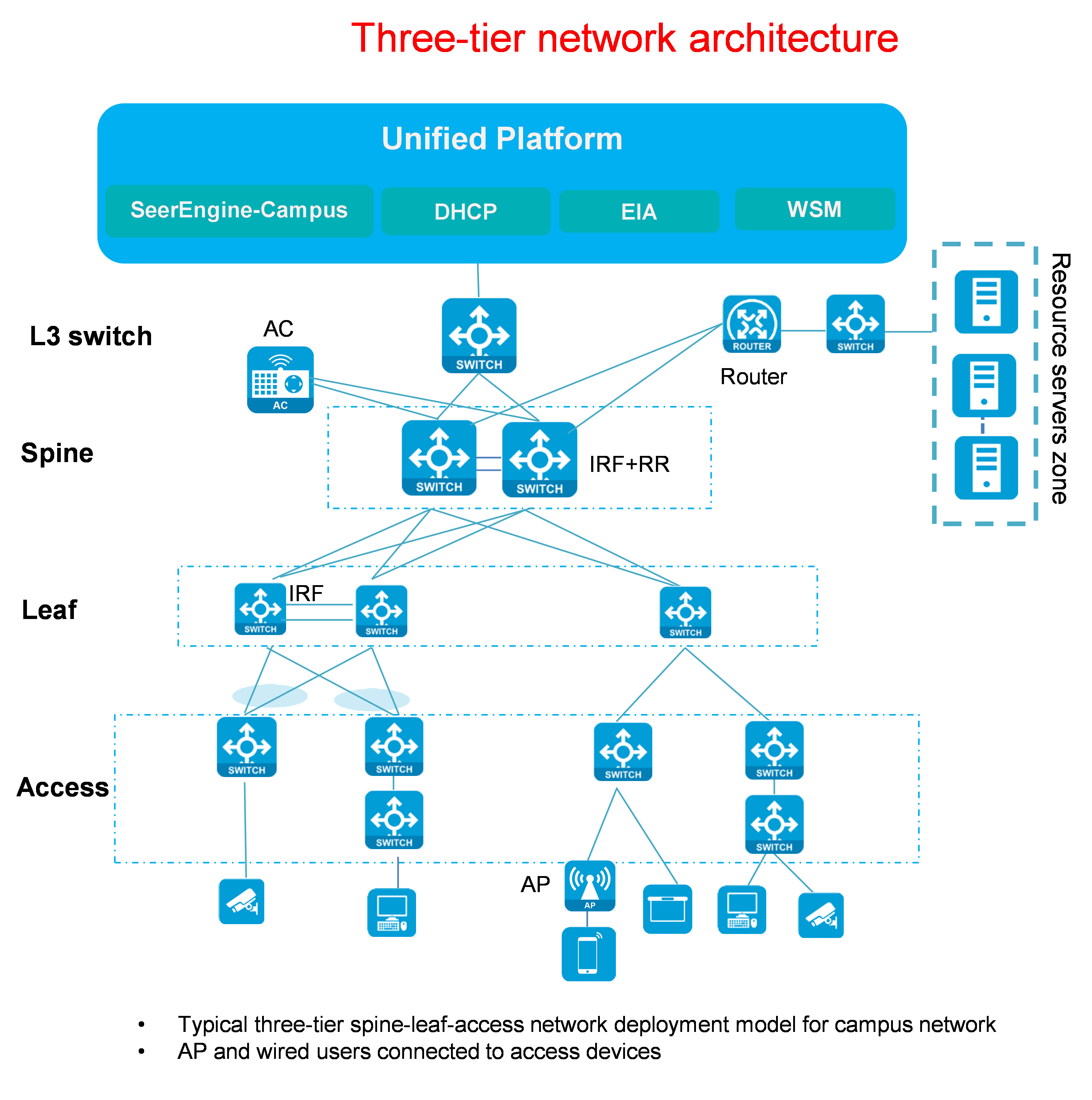
Three-tier network description:
· SeerEngine-Campus controller: Physical server/virtual machine on which the SeerEngine-Campus controller software is installed.
· DHCP Server: H3C-developed DHCP Server that provides IPs for underlay devices.
· Layer 3 switch: Layer 3 switch that provides Layer 3 forwarding and DHCP Relay functions. The Layer 3 switch is manually configured by users and is not managed by the controller. The Layer 3 switch connects the Campus controller, the DHCP Server, and the uplink port of the spine device.
· Spine/leaf/access supports standalone or IRF stacking mode.
· Multiple spine-leaf links form ECMP routes. Multiple leaf-access links are aggregated.
Two-tier network
Figure 2 Two-tier network diagram

Two-tier network description:
· Compared with the three-tier architecture, the two-tier architecture does not contain access devices. Instead, it contains spine devices and leaf devices only.
· Its network elements are the same as those of the three-tier network. For more information, see "Three-tier network."
· Spine/leaf supports standalone or IRF stacking mode.
· Multiple spine-leaf links form ECMP routes.
Single-leaf network
Figure 3 Single-leaf network diagram
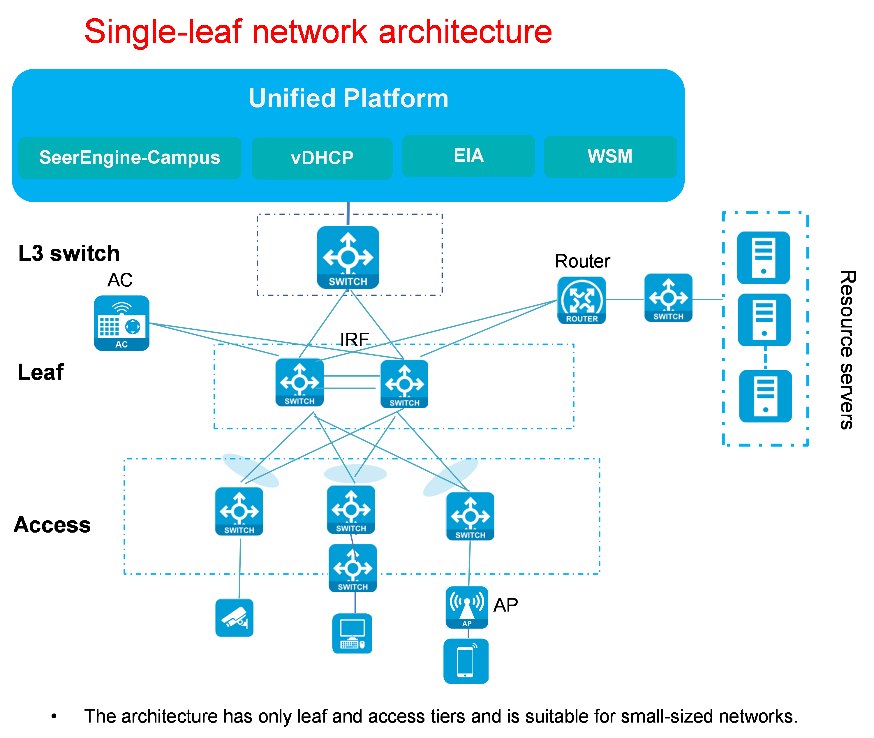
Single-leaf network description:
· Compared with the three-tier architecture, the single-leaf architecture contains no spine devices. It contains leaf devices and access devices only and is suitable for small networks.
· Its network elements are the same as those of the three-tier network. For more information, see "Three-tier network."
· Leaf/access supports standalone or IRF stacking mode.
· Multiple leaf-access links are aggregated.
Aggr + three-tier/two-tier network
Figure 4 Aggr three-tier network diagram
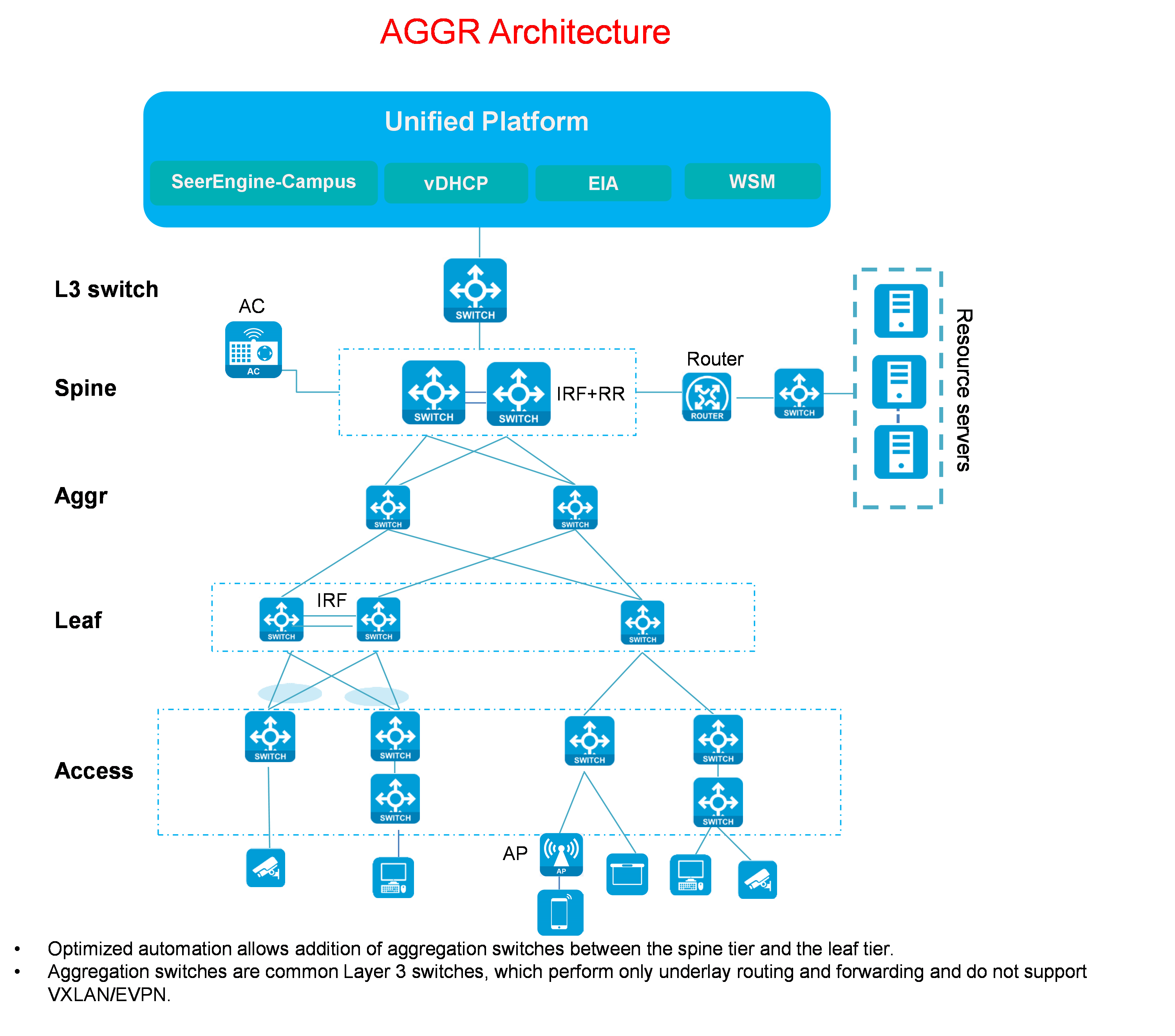
Aggr three-tier/two-tier network description:
· Compared with the typical three-tier/two-tier network, the Aggr network adds Layer 3 aggregation switches between the spine tier and the leaf tier. The Layer 3 aggregation switches do not need to support VXLAN/EVPN.
· Its network elements are the same as those of the three-tier network. For more information, see " Three-tier network."
· Spine/leaf/access supports standalone or IRF stacking mode.
· Between the spine/leaf tier and the Aggr tier, multiple links form ECMP routes.
· Multiple leaf-access links are aggregated.
Access RRPP ring network
Figure 5 Access RRPP ring network diagram
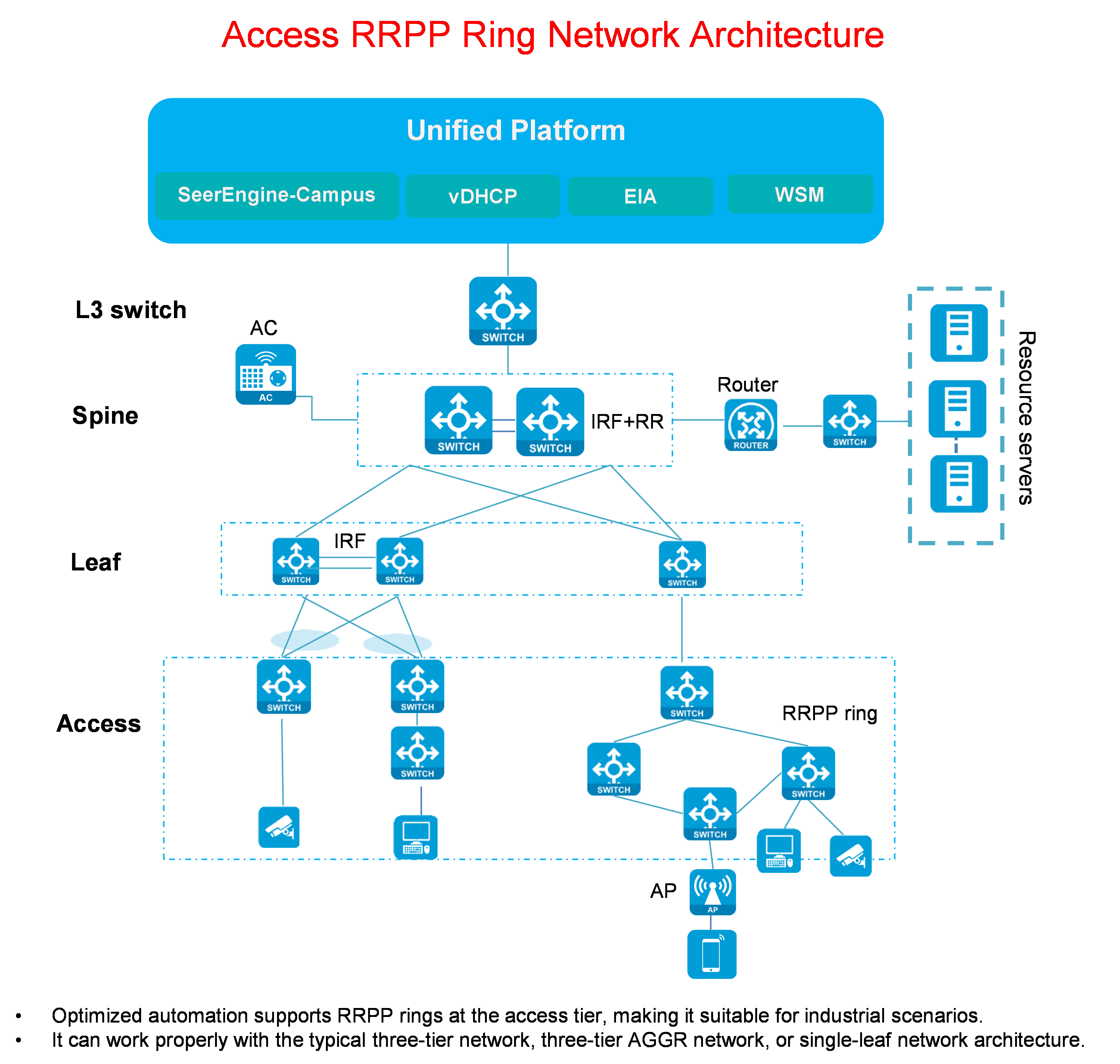
Access RRPP ring network description:
· Compared with the previous network architectures, the RRPP ring network architecture adds an RRPP ring network feature for the access role.
· Its network elements are the same as those of the three-tier network. For more information, see "Three-tier network."
· The access devices in an RRPP ring are connected by single links.
Automated deployment workflow
Figure 6 Automated deployment workflow
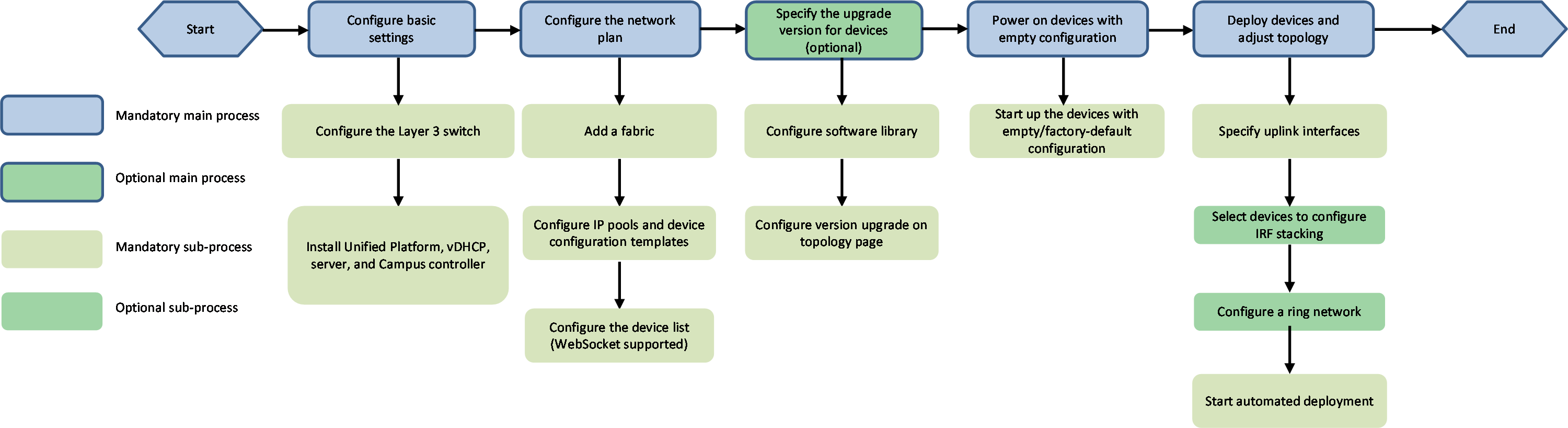
1. Configure basic settings:
¡ The Layer 3 switch is not managed by the controller. You need to manually configure the switch. On the switch, configure DHCP relay of VLAN 1 and permit VLAN 1 and VLAN 4094 on the interface connected to the spine/single-leaf uplink.
¡ Install Unified Platform, vDHCP server, and the Campus controller. On Unified Platform, deploy the vDHCP server so that the devices can automatically acquire IPs during automated device deployment.
2. Prepare network resources:
¡ Create a fabric, and specify an AS.
¡ Configure IP pool settings, including the DHCP server and IP address pools used for automation. Configure device automation templates, including network model, underlay VLAN range, IPs, and NTP server information.
¡ Add devices to the device list and select WebSocket (the controller will register the added devices through WebSocket). The system uses the settings in the device list for automated deployment of the devices. These settings include hardware SNs of the device, its device role, VTEP IP address, management IP address, and system name.
3. Specify the upgrade version for devices:
¡ Upload the IPE package/package group of the target version in Configuration Options > Software Library.
¡ On the topology page, specify the upgrade target version for a device model by device role.
4. Power on the devices with empty configuration
¡ Power on the device with empty/factory-default configuration. The device enters automation process. During the process, the software upgrade task will be performed automatically if configured for the device.
5. Onboard the devices and adjust topology:
¡ The device enters the automation process, obtains the VLAN 1 address and establishes a WebSocket connection with the controller, and displays the corresponding node information on the automation topology page. On the page, manually specify the uplink ports of the spine/single-leaf devices.
¡ You can select devices of the same model and the same role to configure IRF stacking, then the devices will be automatically stacked. (This step is optional.)
¡ Enter the automation topology page, select a device node and click Start Automated Deployment, then the selected device is automatically configured and incorporated into the controller.
Configuration procedure
Planning resource and IP address network
Before starting the configuration procedure, prepare the network. The SeerEngine-Campus controller and Unified Platform can share one network adapter or use different network adapters.
SeerEngine-Campus controller and Unified Platform sharing one network adapter
In this case, the SeerEngine-Campus, vDHCP, EIA, and Unified Platform use the IP addresses in the same network segment. The network diagram is shown below.
Figure 7 SeerEngine-Campus controller and Unified Platform share one network adapter
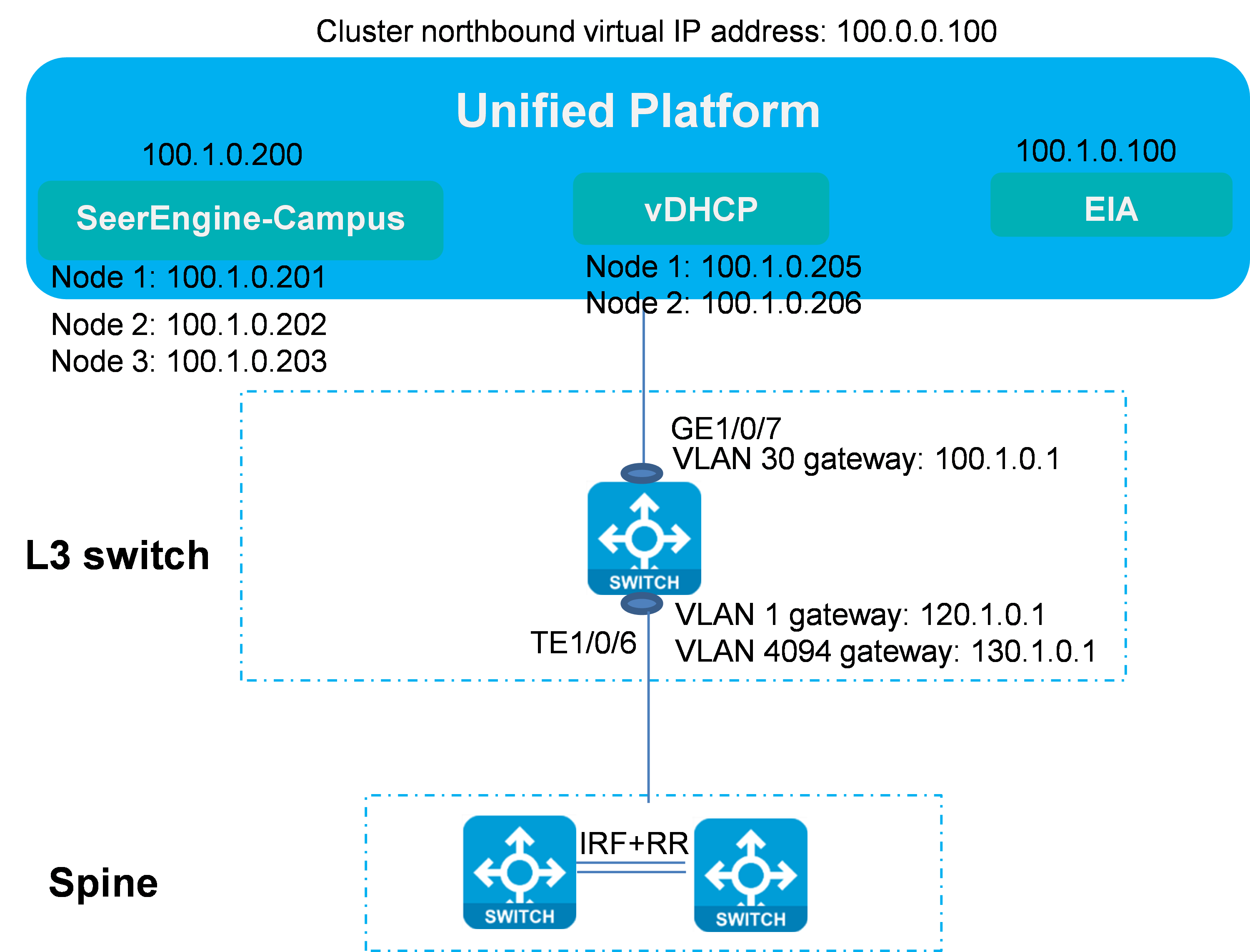
The IP address planning is listed below.
Table 2 Server IP list
|
Item |
Example |
Description |
|
VLAN 1 network segment (gateway) |
120.1.0.0/24 (120.1.0.1) |
VLAN 1 network for automated deployment |
|
VLAN 4094 network segment (gateway) |
130.1.0.0/24 (130.1.0.1) |
VLAN 4094 network for communication between the controller and devices |
|
VLAN 30 network segment (gateway) |
100.1.0.0/24 (100.1.0.1) |
Network segment used by Unified Platform, SeerEngine-Campus, and vDHCP |
|
Network segment of the Underlay IP address |
200.1.1.0/24 |
Network segment of the IP addresses of the loopback interfaces on spine and leaf devices |
|
Unified Platform northbound service IP address |
100.1.0.100 |
IP address for logging in to Unified Platform |
|
EIA |
100.1.0.100 |
Address of the EIA server, which is the address of Unified Platform |
|
SeerEngine-Campus cluster IP address |
100.1.0.200 |
IP address of the SeerEngine-Campus cluster |
|
SeerEngine-Campus node IP addresses |
Node 1: 100.1.0.201 Node 2: 100.1.0.202 Node 3: 100.1.0.203 |
IP addresses of the three nodes in the SeerEngine-Campus cluster |
|
vDHCP cluster IP address |
100.1.0.204 |
Cluster IP address of the vDHCP Server (not used actually) |
|
vDHCP node IP addresses |
Node 1: 100.1.0.205 Node 2: 100.1.0.206 |
IP addresses of the two nodes in the vDHCP Server |
SeerEngine-Campus controller and Unified Platform using different network adapters (recommended)
In this case, SeerEngine-Campus controller and Unified Platform use two different network adapters and IP addresses of two network segments. EIA and Unified Platform cluster use one network segment, while the SeerEngine-Campus and vDHCP use another network segment, as shown in the figure below.
Figure 8 SeerEngine-Campus controller and Unified Platform use different network adapters
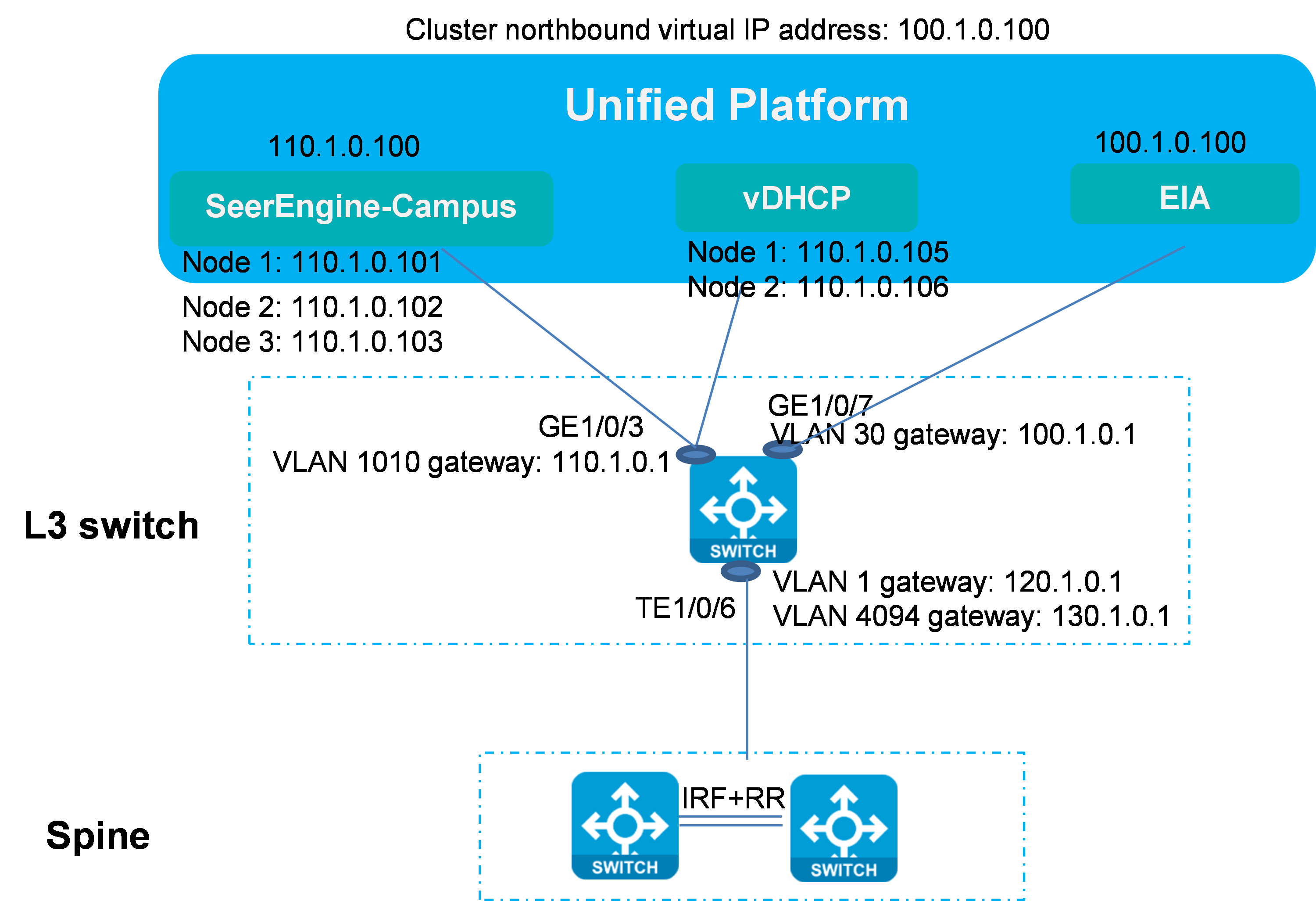
According to the network diagram, the SeerEngine-Campus and vDHCP are deployed based on Unified Platform, the controller and vDHCP share one physical network adapter, and the Layer 3 switch is connected to the controller and vDHCP through a network cable.
Add the Layer 3 switch's port connected to the server to VLAN 1010 (any VLAN other than VLAN 1 and VLAN 4094). This VLAN acts as the management VLAN for the controller and vDHCP, which ensures Layer 3 connectivity with the Layer 3 switch. The network segment is 110.1.0.0/24.
On the L3 switch, configure VLAN-interface 1 and VLAN-interface 4094 for communication with devices. Enable DHCP. Enable DHCP relay on VLAN-interface 1.
This document assumes that the SeerEngine-Campus controller and Unified Platform use different network adapters and gives the address planning as follows.
Table 3 IP resource list
|
Item |
Example |
Description |
|
VLAN 1 network segment (gateway) |
120.1.0.0/24 (120.1.0.1) |
VLAN 1 network for automated deployment |
|
VLAN 4094 network segment (gateway) |
130.1.0.0/24 (130.1.0.1) |
VLAN 4094 network for communication between the controller and devices |
|
VLAN 30 network segment (gateway) |
100.1.0.0/24 (100.1.0.1) |
Network segment used by Unified Platform for communication with PCs |
|
VLAN 1010 (gateway) |
110.1.0.0/24 (110.1.0.1) |
Network segment used by SeerEngine-Campus and vDHCP for communication between the controller and PCs (configured when SeerEngine-Campus uses an independent network adapter) |
|
Network segment of the Underlay IP address |
200.1.1.0/24 |
Network segment of the IP addresses of the loopback interfaces on spine and leaf devices |
|
Unified Platform northbound service IP address |
100.1.0.100 |
IP address for logging in to Unified Platform |
|
EIA |
100.1.0.100 |
IP address of the EIA server |
|
SeerEngine-Campus cluster IP address |
110.1.0.100 |
IP address of the SeerEngine-Campus cluster |
|
SeerEngine-Campus node IP addresses |
Node 1: 110.1.0.101 Node 2: 110.1.0.102 Node 3: 110.1.0.103 |
IP addresses of the three nodes in the SeerEngine-Campus cluster |
|
vDHCP cluster IP address |
110.1.0.104 |
Cluster IP address of the vDHCP Server (not used actually) |
|
vDHCP node IP addresses |
Node 1: 110.1.0.105 Node 2: 110.1.0.106 |
IP addresses of the two nodes in the vDHCP Server |
Configuring the Layer 3 switch
1. Enable DHCP and STP globally.
# Enable DHCP.
mpathconf –enable
#
# Enable STP.
stp global enable
#
2. Configure VLAN-interface 1 and VLAN-interface 4094.
#
interface Vlan-interface1
ip address 120.1.0.1 255.255.255.0
dhcp select relay //DHCP Relay is used for automated device deployment. If spine/leaf/access devices are manually configured and incorporated, DHCP Relay is not required.
dhcp relay server-address 110.1.0.105 //IP address of the vDHCP Server node.
dhcp relay server-address 110.1.0.106
#
vlan 4094
#
#
interface Vlan-interface4094
ip address 130.1.0.1 255.255.255.0
#
3. Create VLAN-interface 30 and VLAN-interface 1010.
#
vlan 30
vlan 1010
#
#
interface Vlan-interface 30
ip address 100.1.0.1 255.255.255.0
#
#
interface Vlan-interface 1010
ip address 110.1.0.1 255.255.255.0
#
4. Configure the interface connected to the spine device.
#
interface Ten-GigabitEthernet1/0/6
description to_spine
port link-type trunk
port trunk permit vlan 1 4094
#
5. Add the interface connected to Unified Platform to VLAN 30.
#
interface GigabitEthernet1/0/7
port access vlan 30
stp edged-port //Configure the port connected the server as the STP edge port.
#
6. Add the interface connected to the SeerEngine-Campus and vDHCP server to VLAN 1010.
#
interface GigabitEthernet1/0/3
port access vlan 1010
stp edged-port //Configure the port connected the server as the STP edge port.
#
Configuring the controller
Restrictions and guidelines
When you install Unified Platform and deploy components, you must install the WebSocket component. In optimized automation, devices need to establish connections with the controller through WebSocket).
Figure 9 Mandatory WebSocket component
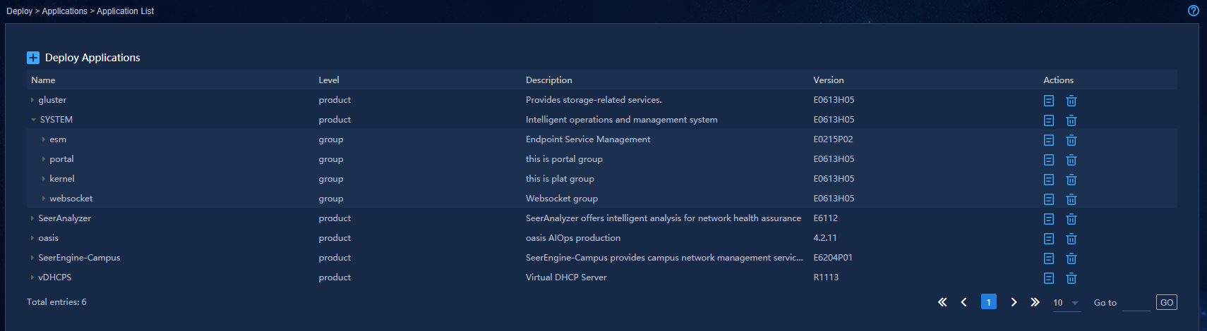
After the Campus controller has been deployed through Unified Platform, enter the controller interface, as shown in the figure below.
Figure 10 Controller interface
Configuring basic settings
1. Navigate to the Guide > Campus Wizard > Device Onboarding Plan > Configure Basic Info page, click the Select Fabric drop-down menu, and select Add Fabric. Specify the following parameters and click OK.
Figure 11 Adding a fabric
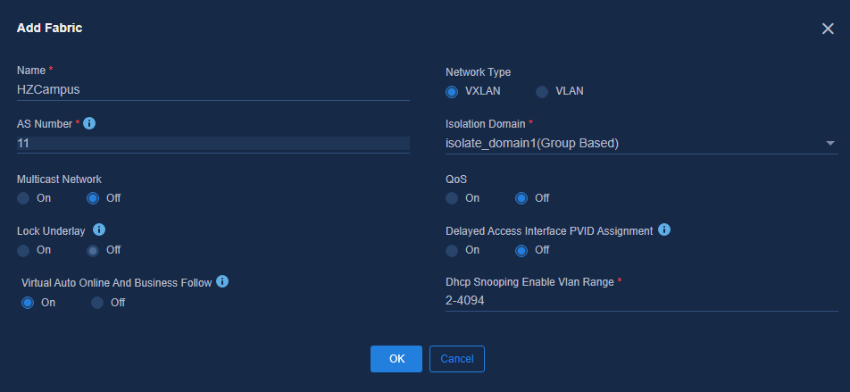
¡ Name: Fabric name, a case-sensitive string up to 255 characters.
¡ Network Type: VXLAN by default.
¡ AS Number: BGP AS number of the fabric, an integer from 1 to 4294967295. During automated deployment, the SeerEngine-Campus controller deploys the BGP AS number to the spine or leaf device added to the fabric based on the AS number set in the fabric.
¡ Isolation Domain: Select the isolation domain to which the fabric belongs. The default is isolate_domain1. Specify an IP policy or group policy through the isolation domain policy mode.
¡ Multicast Network: It is Off by default. You can select On if necessary.
¡ Lock Underlay: It is Off by default.
¡ QoS: It is Off by default. You can select On if necessary.
¡ Delayed Access Interface PVID Assignment: It is Off by default and the controller will automatically assign a PVID when the access device is activated. If you select On, the controller will not assign a PVID when the access device is activated, and you can manually configure the PVID when needed.
¡ Virtual Auto Online And Business Follow: It is On by default. It is used to control the authorization of the VXLAN network and the authorization of access policies between security groups.
2. Use Optimized Automated Deployment: Select Yes.
Configuring address pools
1. To configure address pools, bind a DHCP server first. Click the drop-down arrow of DHCP Server, and select Add DHCP Server. On the page that opens, specify the related parameters of H3C vDHCP.
Figure 12 Adding a DHCP server
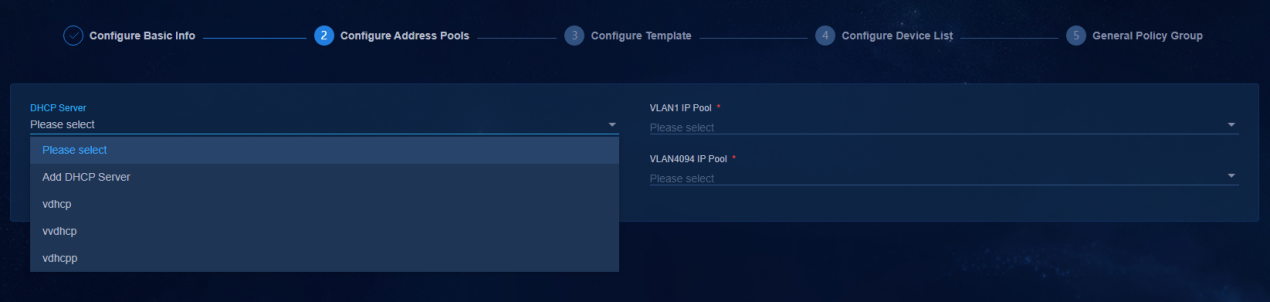
Figure 13 Configuring the DHCP server
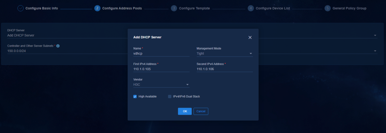
¡ Management Mode: Select Tight because vDHCP only supports this mode.
¡ High Available: Select this option in cluster environment. In standalone mode, you do not need to select this option.
¡ IPv4/IPv6 Dual Stack: Select this option when IPv6 service is used. You do not need to select this option for the optimized automation service as it supports onboarding only IPv4 devices. You can select this option according to the needs of other services.
¡ IP
Address: IP address assigned to vDHCP during
deployment of the public network. It can be viewed on the vDHCP deployment
page. Navigate to the System > Deployment, expand Public
Service page, and click the ![]() icon to view the
details.
icon to view the
details.
¡ Vendor: Select H3C.
|
|
NOTE: The DHCP server for automated device deployment must be the H3C vDHCP server. |
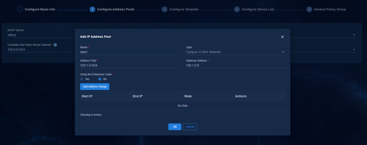
2. Add an address pool for VLAN 1. In the Address Pool field, enter the network segment of VLAN 1 (120.1.0.0/24) set on the Layer 3 switch. In the Gateway Address field, enter the IP address of VLAN 1 set on the Layer 3 switch.
Figure 14 VLAN 1 address pool
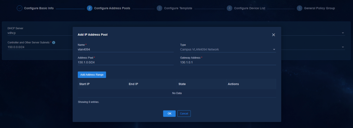
3. Add an address pool for VLAN 4094. In the Address Pool field, enter the network segment of VLAN 4094 (130.1.0.0/24) set on the Layer 3 switch. In the Gateway Address field, enter the IP address of VLAN 4094 set on the Layer 3 switch.
Figure 15 VLAN 4094 address pool
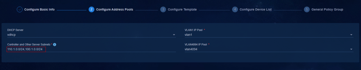
4. Controller and Other Server Subnets: During automated device deployment, the SeerEngine-Campus controller deploys the static route of the configured IP address segment to the device. Select the network segment of VLAN 1010 (110.1.0.0/24) set on the Layer 3 switch and the network segment of VLAN 30 (100.1.0.0/24) of Unified Platform. Multiple network segments can be added and separated by commas.
Figure 16 Configuring the IPv4 management network segment of the server
Configuring device role templates
Select a network model on the page: Three-Tier Architecture, Two-Tier Architecture, Single-Leaf Architecture, Aggr + Two-Tier Architecture, and Aggr + Three-Tier Architecture.
· Auto-Allocate Underlay IP: Option Yes is selected by default. You do not need to enable this function for a single-leaf network.
¡ Yes: The controller automatically assigns IP addresses to the loopback 0 interfaces of the spine and leaf devices from the address segment of the Underlay IP Range set in the template.
¡ No: You need to manually assign IP addresses to the loopback 0 interfaces of the spine and leaf devices. When it is set to No, you must specify the Underlay IP addresses of the devices in the device list.
· Underlay IP Range: Specify the IP address range. It is used to assign IP addresses to loopback 0 interfaces. You do not need to configure this parameter for a single-leaf network.
· Underlay VLAN Range: Specify the available VLAN range. As a best practice, use the default settings. You do not need to configure this parameter for a single-leaf network.
· NTP Server: You can enter the IP address of the NTP time server in the customer network to ensure network connectivity.
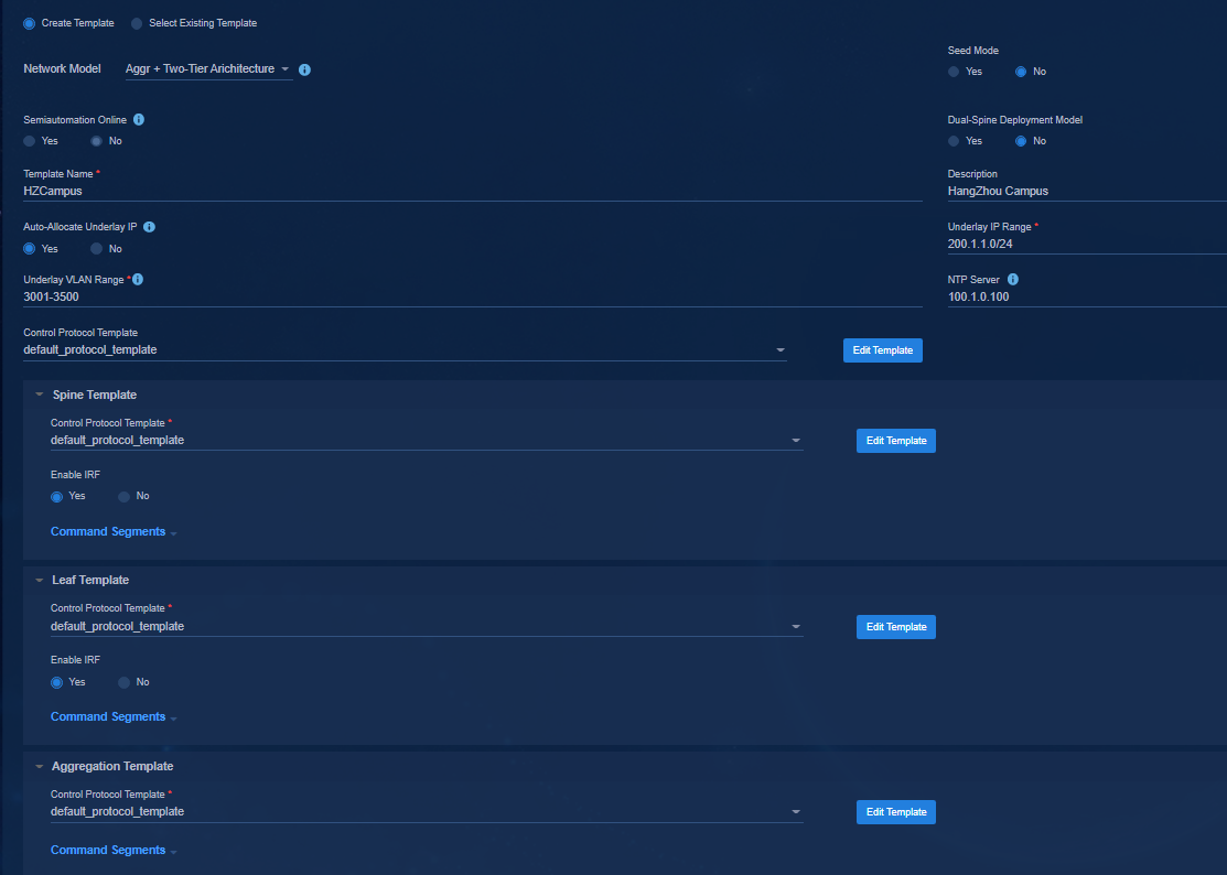
· Control Protocol Template: The password is not set in the initial control protocol template. You need to click Edit Template to change the password. The protocol template contains SNMP parameters and NETCONF parameters used by the controller to incorporate the automatically onboarded devices. A three-tier architecture requires configuring spine, leaf, and access templates. A two-tier architecture requires configuring spine and leaf templates. A single-leaf architecture requires configuring leaf and access templates. An aggr + three-tier architecture requires configuring spine, leaf, access, and aggregation templates. An aggr + two-tier architecture requires configuring spine, leaf, and aggregation templates.
Figure 17 Configuring templates for a three-tier architecture
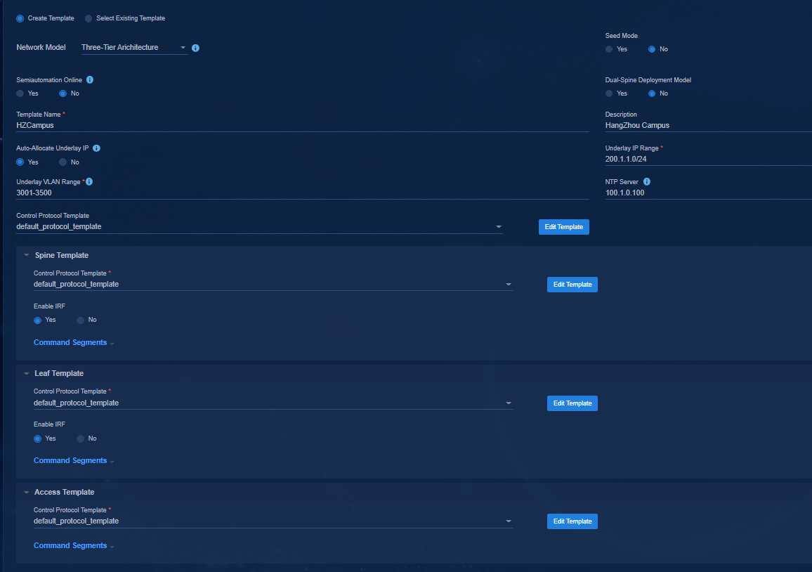
Figure 18 Configuring templates for a two-tier architecture
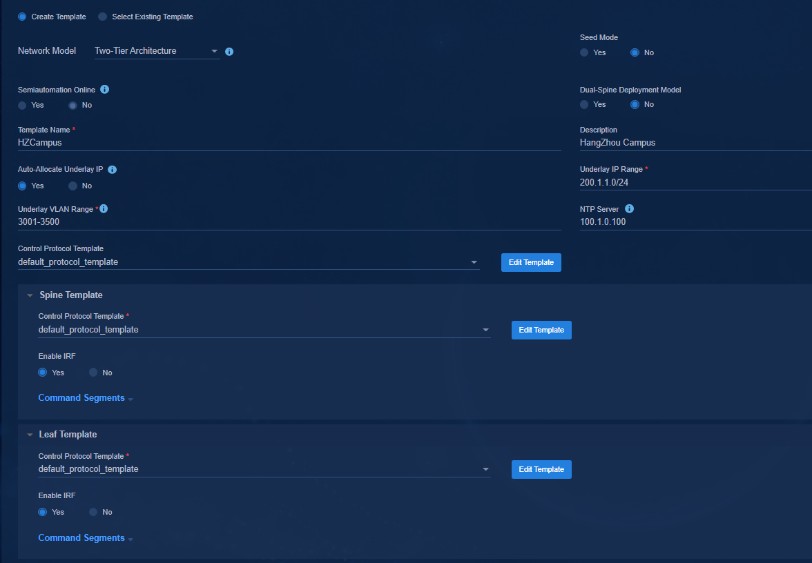
Figure 19 Configuring templates for a single-leaf architecture
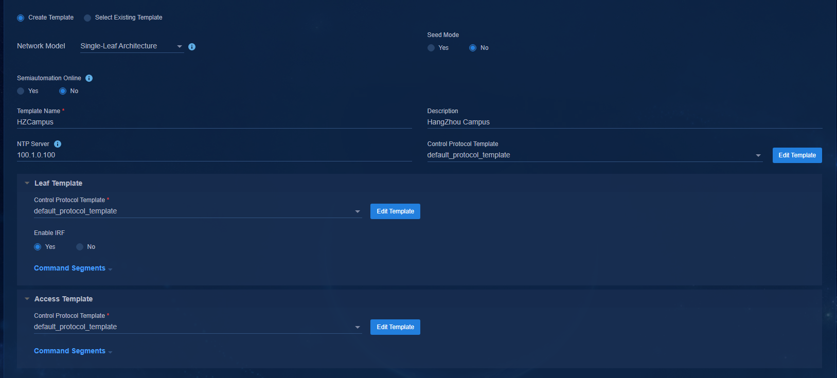
Figure 20 Configuring templates for an aggr + three-tier architecture
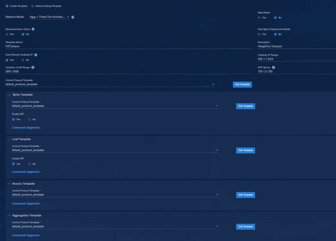
Figure 21 Configuring templates for an aggr + two-tier architecture
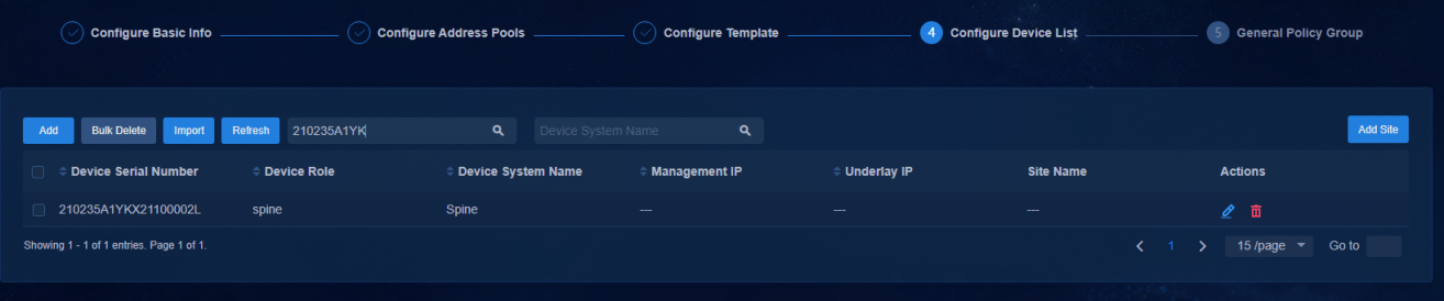
Configuring a device list for automated deployment
The optimized automated deployment requires adding a device list. Otherwise, the devices cannot be onboarded. In the device list, you can configure the following settings for each device:
· Specify the device role and preconfigure the role information for automated device deployment.
· Allow the device to register with WebSocket. If the serial number of the specified device is in the device list, the device can establish a WebSocket connection and complete automated deployment through the connection. Otherwise, the automated deployment will fail.
Navigate to the Guide > Campus Wizard > Device Onboarding Plan > Device List page to add or import device list entries.
· Network Type: VXLAN (default).
· WebSocket: Select Yes. It indicates that the device can communicate with the controller over WebSocket protocol.
· Device Serial Number: Enter the unique identifier of the device. You can obtain it by executing the following commands.
- On the S10500X/S10500 series, execute the following command: display license device-id chassis *
- On fixed-port devices (S6550XE/S6525XE/6520X/S5560X series), execute the following command: display license device-id slot *
- On the S7500X series, execute the following command: display license device-id chassis *
- On the fixed-port S51 series, execute the following command: display device manuinfo slot *
To view serial number details, execute the following command:
<spine1>display license device-id chassis 1
SN: 210235A1YKX21100002L
Device ID: vqCk-Eq3e-NJpu-tCG$-uCyD-938M-piZA-c463
or
<access1>display device manuinfo slot 1
Slot 1 CPU 0:
DEVICE_NAME : S5130S-52S-EI
DEVICE_SERIAL_NUMBER : 219801A12F9191Q00251
MAC_AddRESS : 7057-BF65-A9C0
MANUFACTURING_DATE : 2019-01-11
VENDOR_NAME : H3C
· Device Role: Spine, leaf, access or aggregation. During the automated device deployment, the device role will be modified automatically according to the role information configured in the device list. If the role is not configured, the device will be deployed using the default role.
· Device System Name: The sysname of the device, which will be modified automatically according to the sysname configured in the device list after the device is onboarded automatically.
· Management IP:
¡ (Optional.) Specify the IP address of the VSI/VLAN 4094 after the device is onboarded automatically.
- If the management IP address is configured, the SeerEngine-Campus controller will assign an IP address to the device according to the management IP address after the device is onboarded.
- If the management IP address is not configured, the SeerEngine-Campus controller will automatically assign an IP address to the device from the IP address pool of VLAN 4094.
¡ Underlay IP: (Optional.) Specify the IP address of the Loopback 0 after the device is onboarded.
- If the Underlay IP address is configured, the SeerEngine-Campus controller will assign an IP address to the device according to the management IP address after the device is onboarded.
- If the Underlay IP address is not configured, the SeerEngine-Campus controller will automatically assign an IP address to the device from the Underlay IP range.
· Site Name: Select the site of the device as required. If you need to use the dashboard function, you must configure the site name.
Figure 22 Adding a device list entry
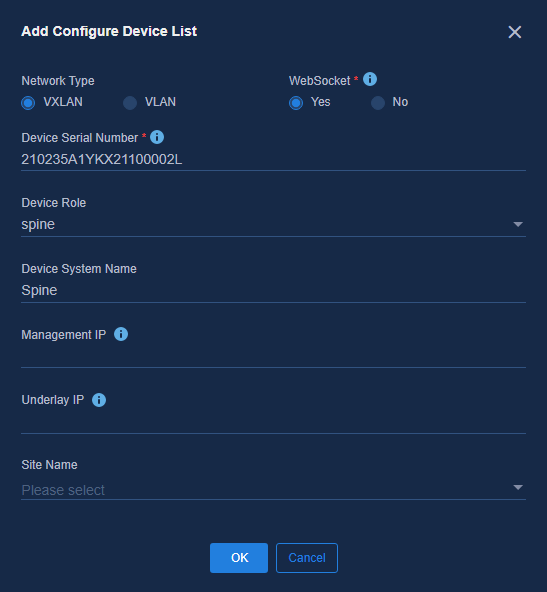
Figure 23 Viewing the device list
Configuring the policy configuration template
The policy configuration template does not affect automated device deployment and is related to user services. For detailed configurations, see AD-Campus 6.2 Basics Configuration Guide.
Upgrading the device (optional)
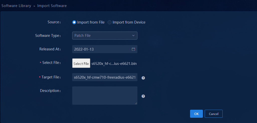
1. Navigate to the Automation > Configuration Options > Software Library menu and click Import in the upper left corner to enter Import Software page. On this page you can import the version file for device upgrade. For Source, you can select Import from File or Import from Device. For Software Type, you can select Image Package Envelope (*.ipe), Software Package Group, or Patch File.
Figure 24 Importing IPE
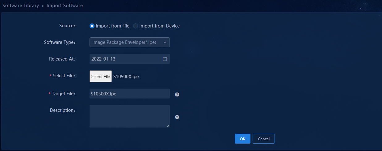
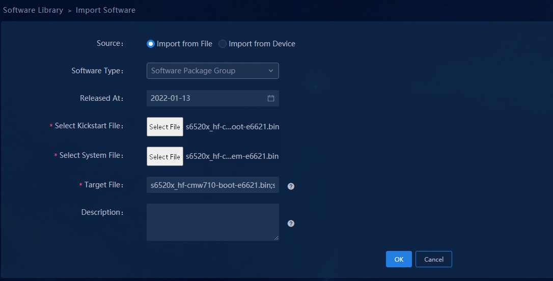
To import the Software Package Group, you need to select both boot and system files. After importing is completed, specify the applicable device model.
Figure 25 Importing the software package group
After a patch package is imported, you need to specify the applicable device model. Feature package also needs to be imported as a patch package.
Figure 26 Importing the patch package
You can read the device startup files directly using Import from Device. It requires the device on the Monitor > Monitor List > Network Monitors page to be online.
Figure 27 Importing from device
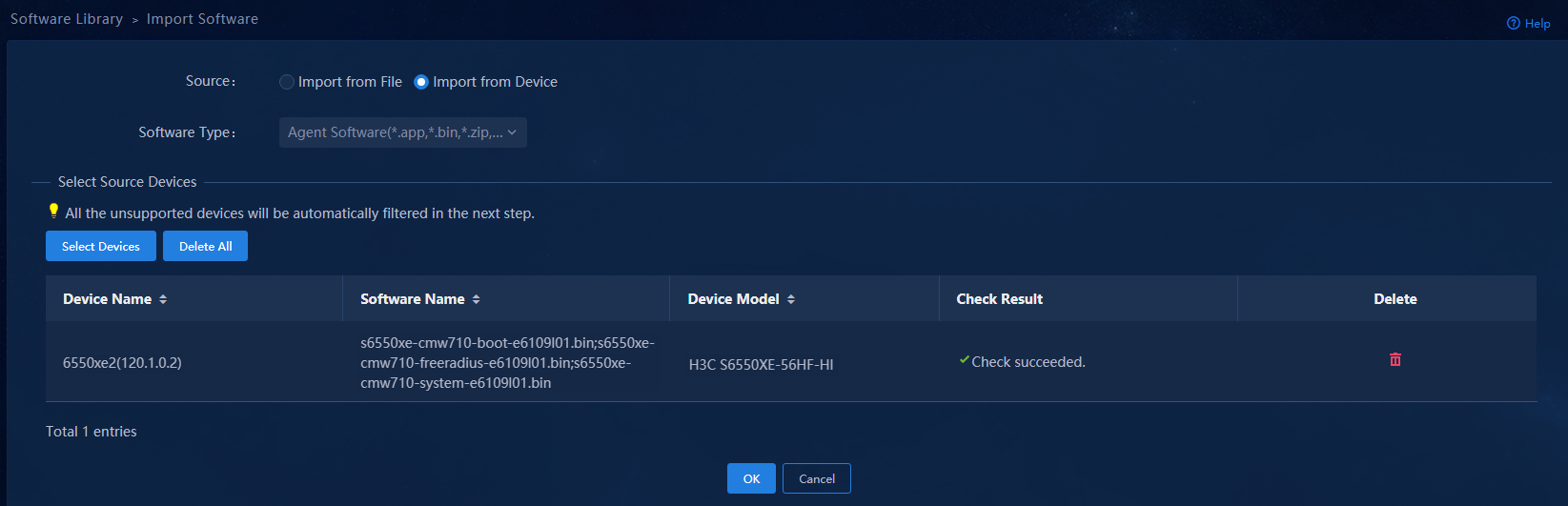
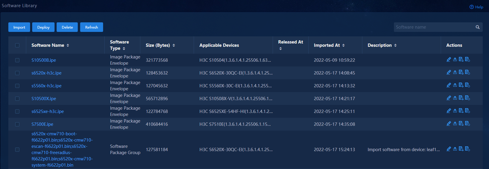
Figure 28 Viewing the software library
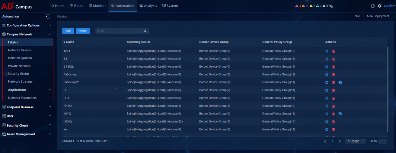
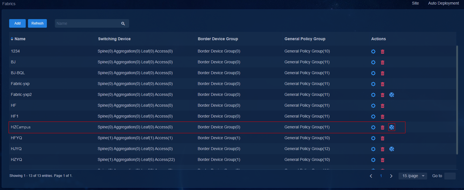
2. Navigate to the Automation > Campus Network > Fabrics page. On the Fabrics page, select a fabric for which the optimized automation template has been created. Click View Topology in the action bar.
Figure 29 Automation topology page

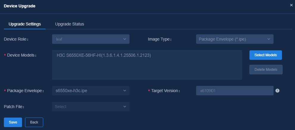
3. On the View Topology page, click Device Upgrade. Select the Device Role and Image Type, and click to configure the applicable devices. Click Select Models to select desired devices on the pop-up page. Then click Add to add devices. You can also select the device to be added and then click Delete Models to delete it. After setting the device models, set Package Group, Target Version, Features Package, and Patch File.
Figure 30 Adding package group
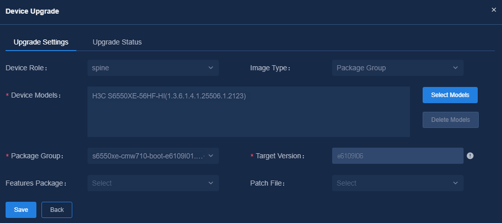
Figure 31 Adding IPE
|
|
NOTE: After obtaining the VLAN-interface 1 address, the device will come online through WebSocket. Any upgrade task will be automatically performed. After the upgrade, the device will be displayed in the topology. Enter the external version number of the program for the Target Version field. |
Automated onboarding
Preparation for automated device onboarding
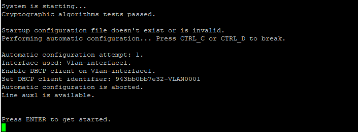
Starting up the devices with empty configuration
Use the restore factory-default command to restore the devices to factory settings and restart the devices.
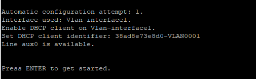
The spine/leaf/access/aggregation device starts up with empty configuration and automatically obtains the IP address of VLAN-interface 1, and then connects to the controller via WebSocket.
Figure 32 Device startup with empty configuration (1)
![]()
Figure 33 Device startup with empty configuration (1)
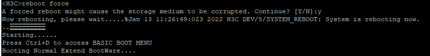
Figure 34 Acquiring VLAN 1 address
Check whether WebSocket connection has been established on the device:
<H3C>display cloud-management state
Cloud connection state : Established
Device state : Request_success
Cloud server address : 100.1.0.100
Cloud server domain name : 100.1.0.100
Cloud server port : 443
Connected at : Thu Jan 13 11:29:12 2022
Duration : 00d 00h 01m 27s
Process state : Message received
Failure reason : N/A
Upgrading devices (optional)
1. Navigate to the Automation > Campus Network > Fabrics > View Topology page to view the topology node information of the device.
Figure 35 Viewing topology
2. On the View Topology page, click Device Upgrade. Then click Upgrade Status to view automatically created upgrade tasks. If the device model corresponding to the current device role contains upgrade configurations, the device will automatically initiate the upgrade process in the following conditions: the device acquires the address through VLAN 1 and comes online; and the cloud detects that the device startup version is inconsistent with the target version.
Figure 36 Automatically creating and executing tasks in the Upgrade Status
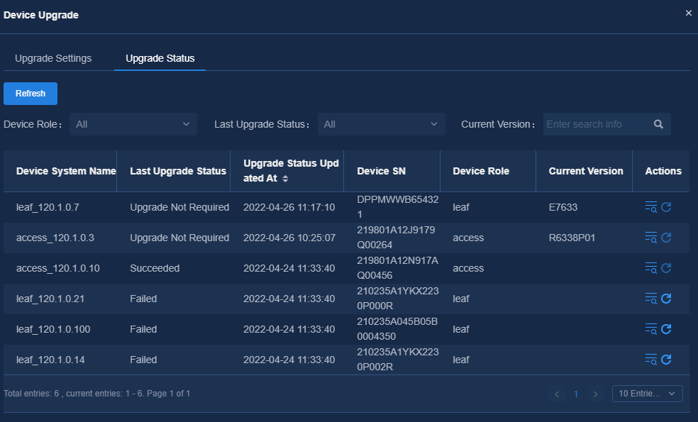
Figure 37 Execution result
![]()
![]()
Figure 38 Detailed upgrade steps
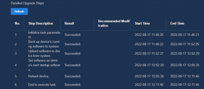
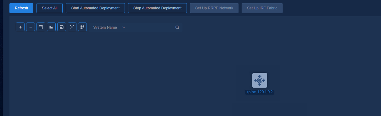
Figure 39 Adding topology view after upgrade
Automated deployment process
Viewing automated deployment topology
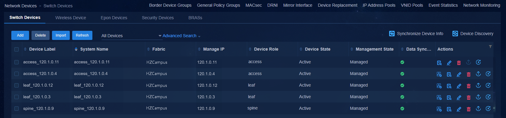
The device automatically comes online, acquires VLAN 1 address, and establishes a WebSocket connection with the controller. After the device has performed the upgrade task, the controller will automatically incorporate the device. Navigate to the Automation > Campus Network > Network Devices page to view the device information, as shown in the figure below.
Figure 40 Network devices
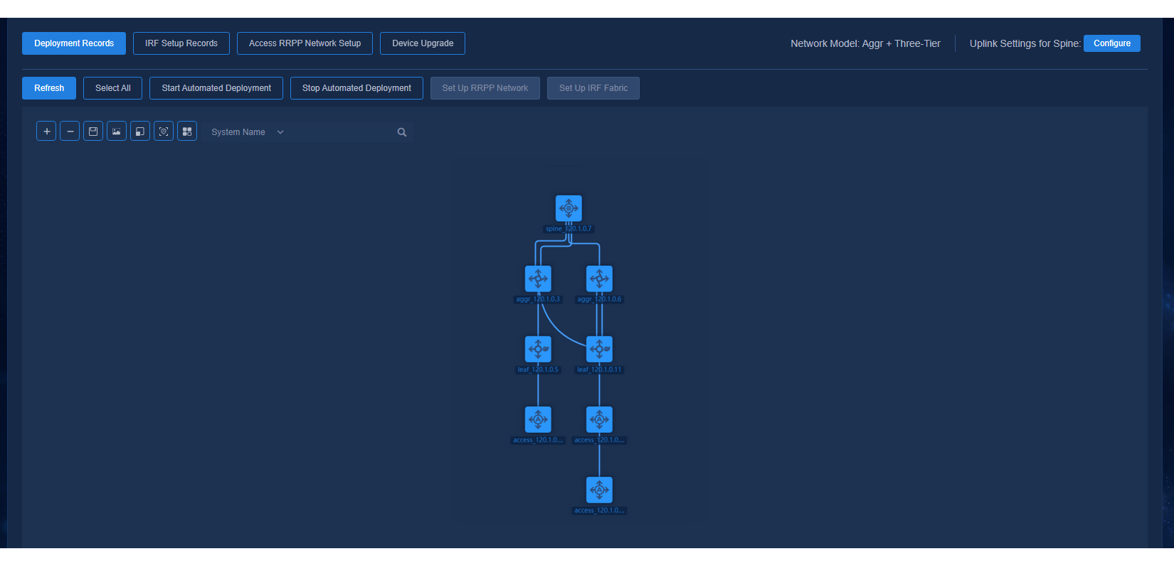
Navigate to the Automation > Campus Network > Fabrics > View Topology page to view the topology node information of the device.
Figure 41 Automated deployment topology for a three-tier architecture
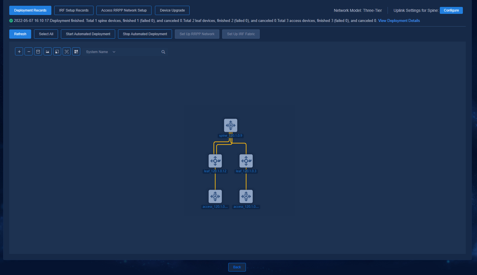
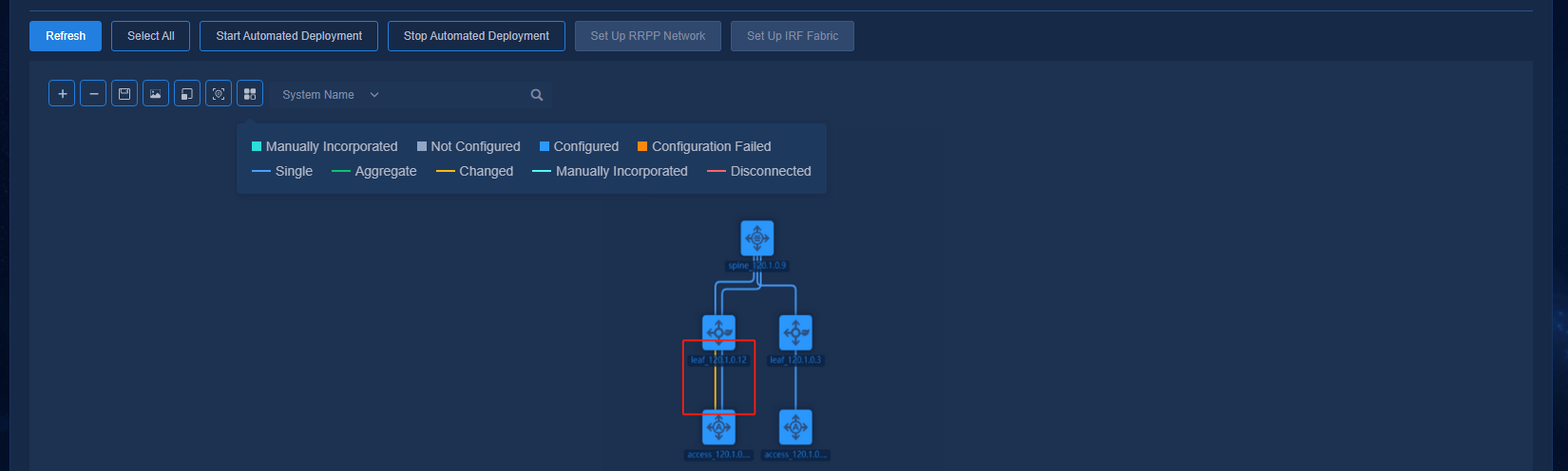
The buttons at the top left of the topology page are Zoom In, Zoom Out, Save Coordinates, Export as Picture, Reset Zoom, Restore Default Topology, and View Legend. The legends are colored to display the status of device configuration and link as follows:
· Device status:
¡ Manually Incorporated (the device is incorporated manually)
¡ Not Configured (the device is not automatically deployed)
¡ Configured (the device is automatically deployed)
¡ Configuration Failed (the automated device deployment failed)
· Link status:
¡ Single (single link)
¡ Aggregate (aggregate link)
¡ Changed (link changed or newly added after automated device deployment)
¡ Manually Incorporated (manually incorporated link)
¡ Disconnected (link removed after automated device deployment)
Figure 42 Viewing legends

The networking schemes are listed below.
Figure 43 Automated deployment topology for a two-tier architecture
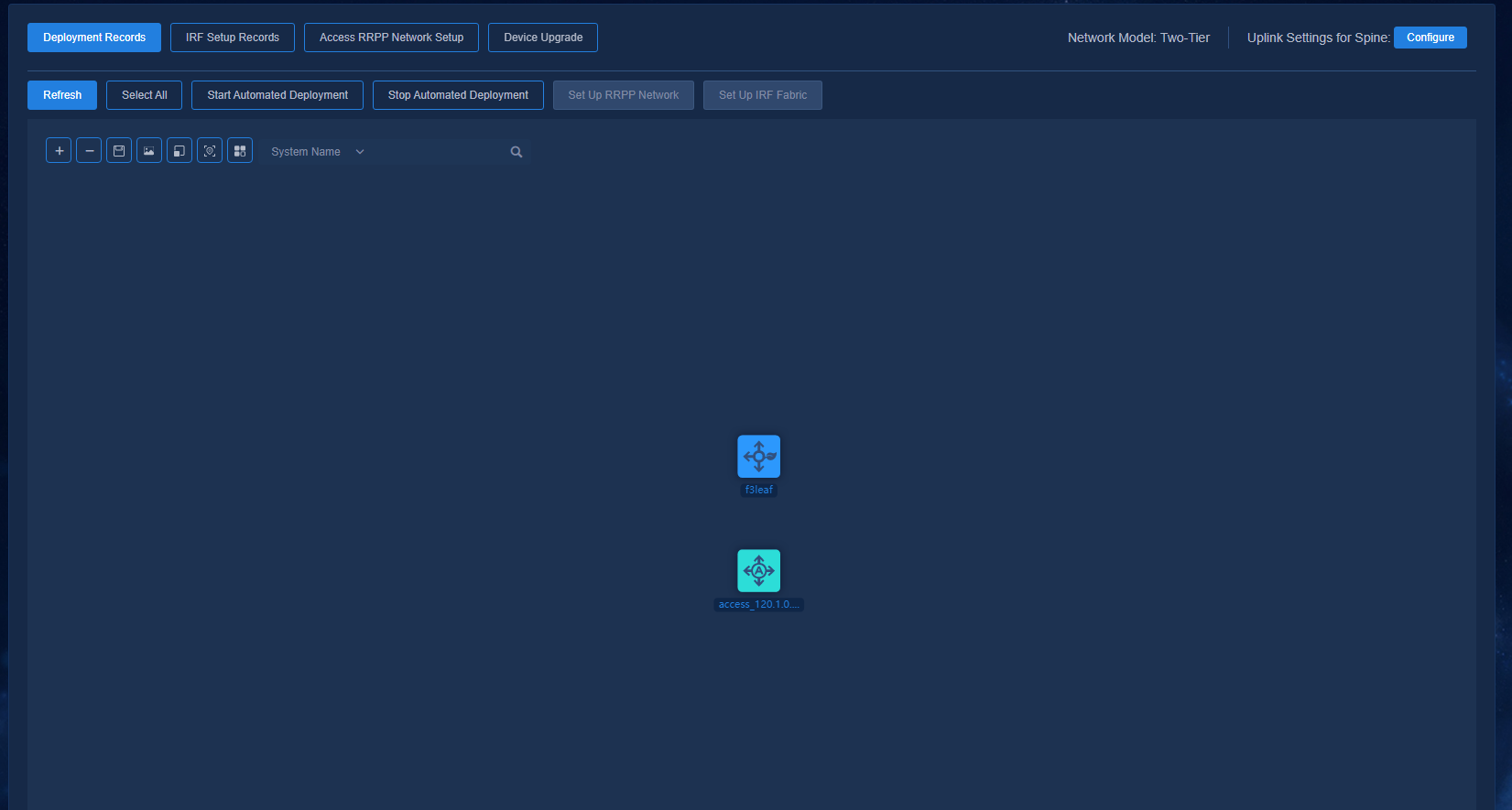
Figure 44 Automated deployment topology for a single-leaf architecture
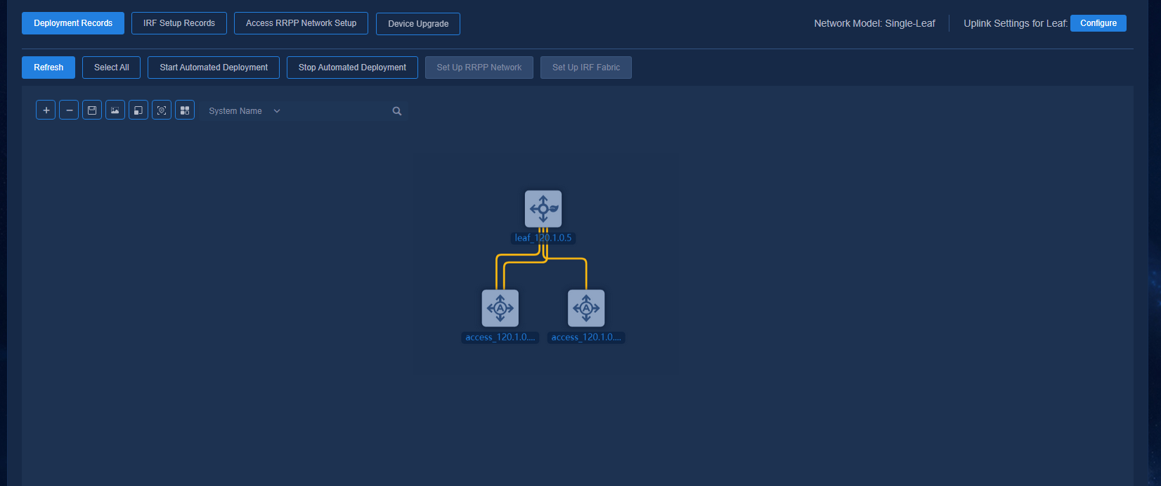
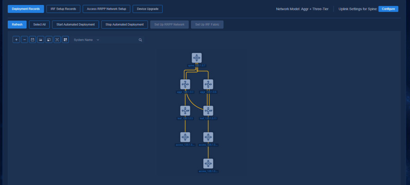
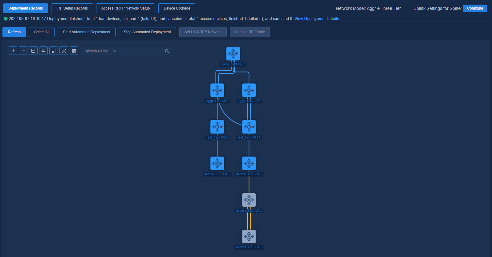
Figure 45 Automated deployment topology for an aggregated architecture
Selecting an uplink interface and adjusting topology
Restrictions and guidelines
If the spine/single-leaf device has two uplink ports, configure aggregation for the ports on the spine/single-leaf device. In addition, you must also manually configure aggregation for the interconnect ports on the peer Layer 3 switch.
Procedure
1. Navigate to the Automation > Campus Network > Fabrics > View Topology page and right-click a spine/single-leaf device. Click Aggregation Configuration to configure aggregation groups.
Figure 46 Right-click spine/single-leaf to perform aggregation configuration
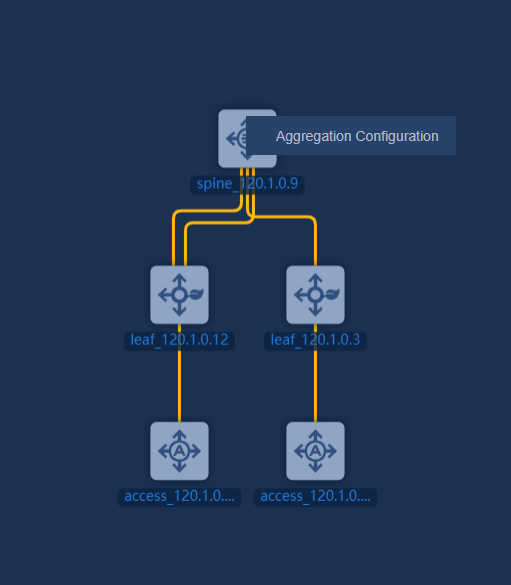
Figure 47 Aggregation configuration
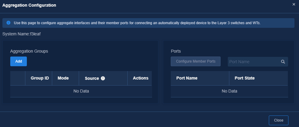
¡ Aggregation Groups: Display all aggregation group information of the device and support creating aggregation groups on the cloud.
¡ Ports: Specify the member ports for aggregation groups.
2. After the aggregation configuration is completed, go back to the topology page and click Configure for uplink settings for spine/leaf in the upper right corner. Select the configured aggregation group or a single uplink and then click Submit to save the settings.
3. After all the devices to be incorporated have acquired the VLAN 1 address, established WebSocket connections with the controller, and completed software upgrade, the controller will display the topology of the entire network. Before the automated deployment starts, you can adjust the topology. For example, you can change the role of a device from the device list, or change links on the real network, so as to set up a topology that meets the user requirements.
Starting automated deployment
The automated deployment topology page displays node and link information of the devices, and you can perform the following operations on the nodes: Start Automated Deployment, Stop Automated Deployment, Set Up RRPP Network, and Set Up IRF Fabric.
Navigate to the Automation > Campus Network > Fabrics > View Topology page and click Select All to select all devices, or press Ctrl and left-click on some devices, and then click Start Automated Deployment. In this case, the automated deployment process will be started for all the selected devices.
Figure 48 Starting automated deployment
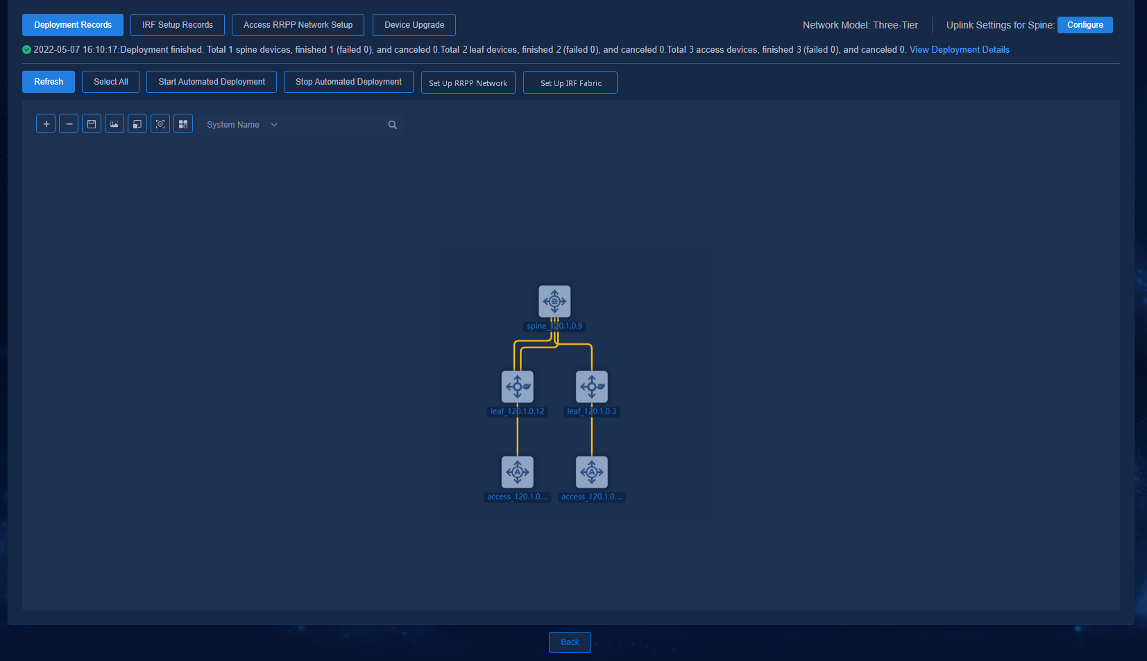
Viewing the automated deployment details
After automated deployment is started for all the devices in the topology, you can view the overall deployment status by using View Deployment Details or Deployment Records.
Double-click a specific spine/leaf/aggr/access device node to view the detailed deployment process of the device.
Viewing the device deployment results
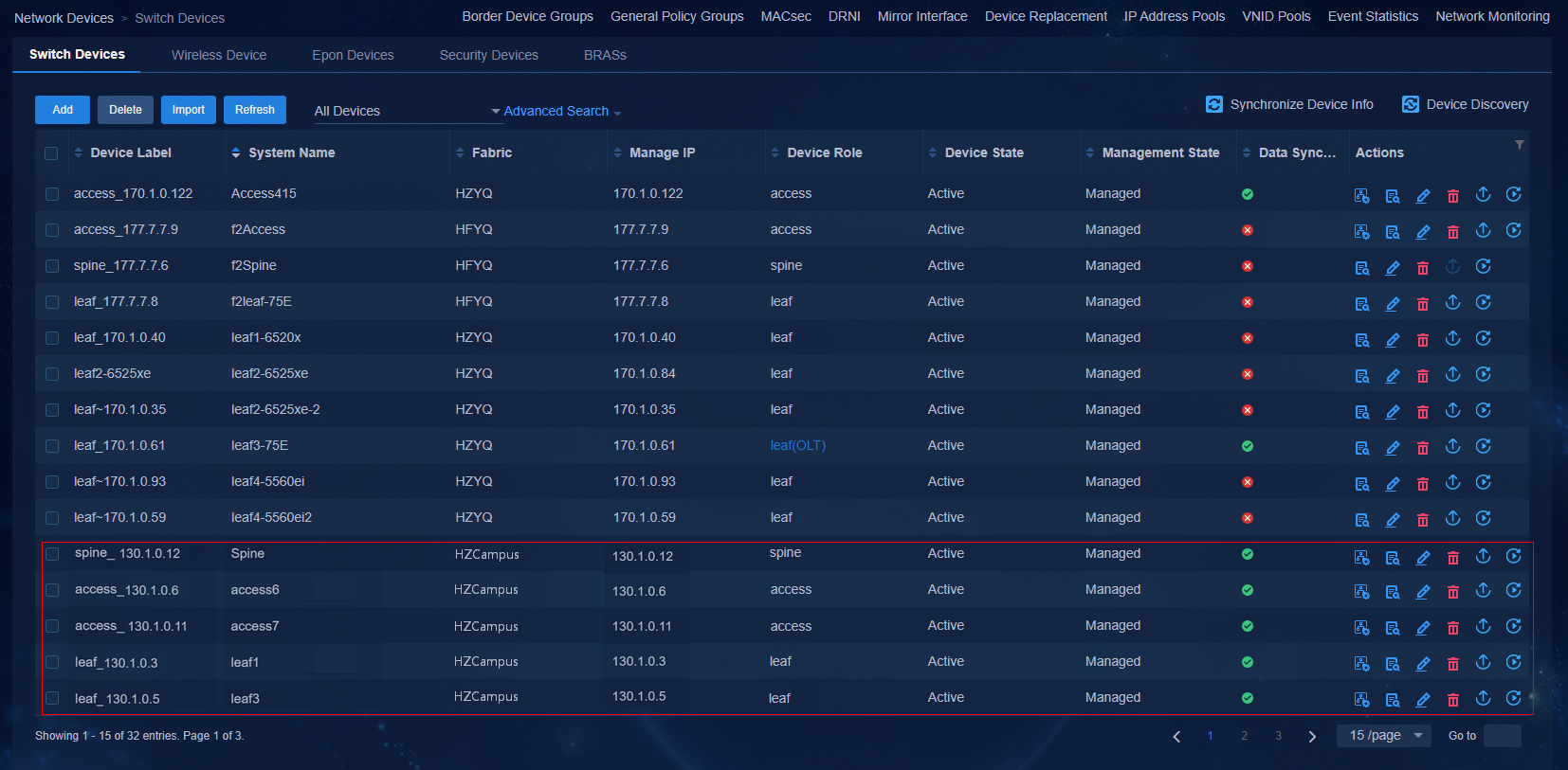
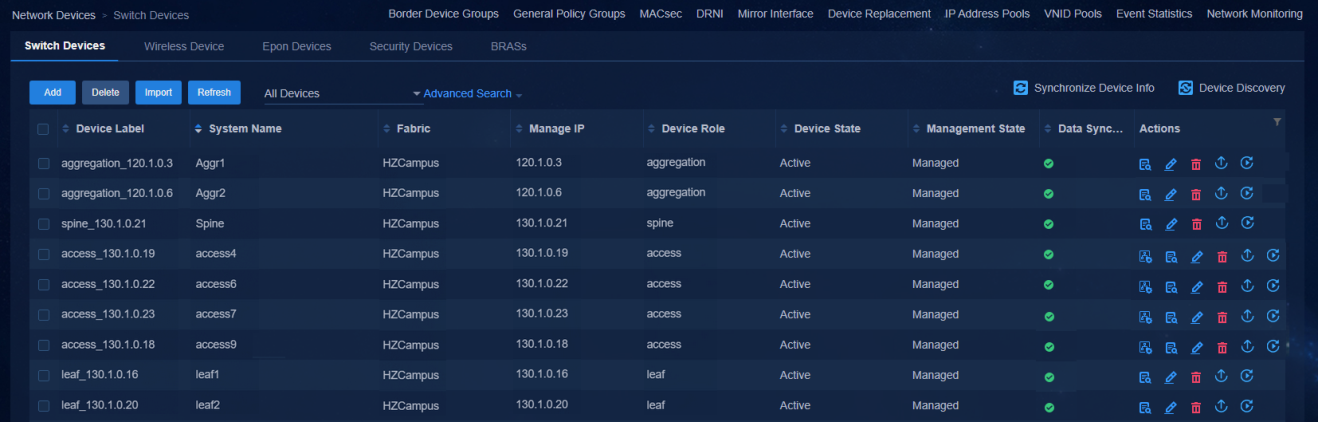
Viewing the status of devices connected to the controller
Navigate to the Automation > Campus Network > Network Devices page to view the device information. All the automatically deployed devices have been successfully upgraded. Device State is Active. Management State is Managed.
Figure 49 Network devices for a three-tier architecture
Navigate to the Automation > Campus Network > Fabrics > View Topology page to view the topology node information of the devices. The link state has been changed to Configured.
Figure 50 Topology for a three-tier architecture
The network devices and topology for different networking schemes are shown below.
Figure 51 Network devices for a two-tier architecture
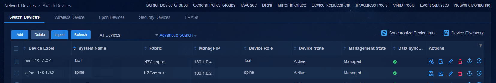
Figure 52 Topology for a two-tier architecture
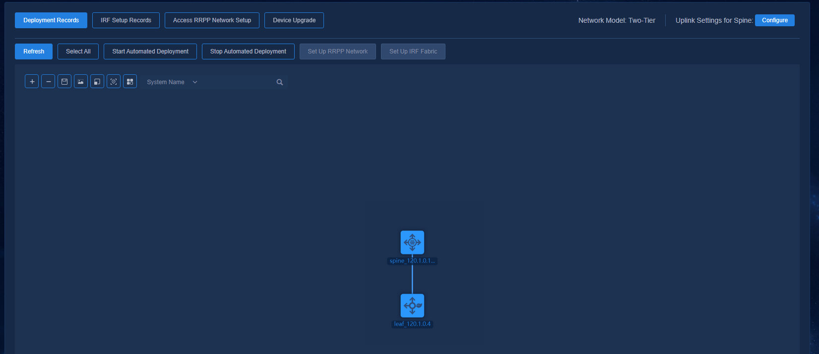
Figure 53 Network devices for a single-leaf architecture
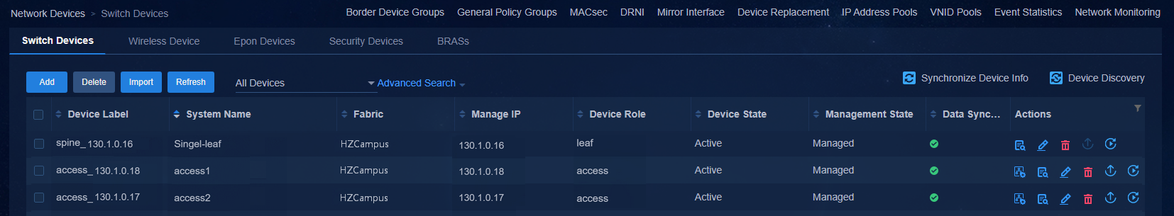
Figure 54 Topology for a single-leaf architecture

Figure 55 Network devices for an aggregated architecture
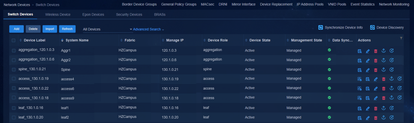
Figure 56 Topology for an aggregated architecture
Verifying the main configuration of the spine device
Three-tier or a two-tier architecture
After the spine device is automatically onboarded, it automatically configures the physical interface connected to the Layer 3 switch as an AC interface.
The aggregated uplink interface of the spine device is configured as follows (dual-uplink):
#
interface Bridge-Aggregation1
port link-type trunk
port trunk permit vlan all
link-aggregation mode dynamic
#
service-instance 4094
encapsulation s-vid 4094
xconnect vsi vxlan4094
#
The physical uplink interface of the spine device is configured as follows (single-uplink):
interface Ten-GigabitEthernet2/0/1
#
port link-mode bridge
port link-type trunk
port trunk permit vlan all
#
service-instance 4094
encapsulation s-vid 4094
xconnect vsi vxlan4094
#
During the automated configuration of the device, you can execute the display interface brief command to monitor the IP assignment status on the spine device. As shown below, the spine device has obtained IP addresses for Loopback interface 0, VLAN-interface 1, and VSI-interface 4094. When there are two links between the spine device and the downlink leaf device, VLAN 3002 and VLAN 3003 are respectively created for the two downlink ports, and the downlinks are automatically configured as ECMP path. The VLAN IDs were assigned by the controller from the underlay VLAN range configured in the automation template.
[Spine]display interface brief | in UP
InLoop0 UP UP(s) --
Loop0 UP UP(s) 200.1.1.2
NULL0 UP UP(s) --
REG0 UP -- --
Tun0 UP UP --
Tun1 UP UP --
Vlan1 UP UP 120.1.0.9
Vlan3001 UP UP 200.1.1.2
Vlan3002 UP UP 200.1.1.2
Vlan3003 UP UP 200.1.1.2
Vsi4092 UP UP 130.1.0.12 SDN_VRF_VSI_Interface_4092
Vsi4094 UP UP 130.1.0.12
BAGG1 UP 20G(a) F(a) T 1
WGE1/0/3 UP 10G(a) F(a) T 1
WGE1/0/4 UP 10G(a) F(a) T 1
WGE1/0/10 UP 10G(a) F(a) T 1
WGE1/0/13 UP 10G(a) F(a) T 1
WGE1/0/40 UP 10G(a) F(a) T 1
The configuration on the spine-leaf interconnect port is as follows: (If the spine device has multiple links to a leaf device, the links are automatically configured as ECMP paths.)
[Spine-Twenty-FiveGigE1/0/40]dis this
#
interface Twenty-FiveGigE1/0/40
port link-mode bridge
port link-type trunk
port trunk permit vlan 1 3002
lldp source-mac vlan 3002
lldp management-address arp-learning vlan 3002
lldp tlv-enable basic-tlv management-address-tlv interface LoopBack0
#
return
[Spine-Twenty-FiveGigE1/0/13]dis this
#
interface Twenty-FiveGigE1/0/13
port link-mode bridge
port link-type trunk
port trunk permit vlan 1 3003
lldp source-mac vlan 3003
lldp management-address arp-learning vlan 3003
lldp tlv-enable basic-tlv management-address-tlv interface LoopBack0
#
return
Verify that ECMP routes over the links have been generated in the routing table:
[Spine]display ip routing-table 200.1.1.3
Summary count : 2
Destination/Mask Proto Pre Cost NextHop Interface
200.1.1.3/32 O_INTRA 10 2 200.1.1.3 Vlan3003
200.1.1.3 Vlan3002
Aggr architecture
After the spine device is automatically onboarded, it automatically configures the physical interface connected to the Layer 3 switch as an AC interface.
The aggregated uplink interface of the spine device is configured as follows (dual-uplink):
#
interface Bridge-Aggregation1
port link-type trunk
port trunk permit vlan all
link-aggregation mode dynamic
#
service-instance 4094
encapsulation s-vid 4094
xconnect vsi vxlan4094
#
The physical uplink interface of the spine device is configured as follows (single-uplink):
interface Ten-GigabitEthernet2/0/1
#
port link-mode bridge
port link-type trunk
port trunk permit vlan all
#
service-instance 4094
encapsulation s-vid 4094
xconnect vsi vxlan4094
#
During the automated configuration of the device, you can execute the display interface brief command to monitor the IP assignment status on the spine device. As shown below, the spine device has obtained IP addresses for Loopback interface 0, VLAN-interface 1, and VSI-interface 4094. When there are two links between the spine device and the downlink Aggr device, VLAN 3006 and VLAN 3007 are respectively created for the two downlink ports, and the downlinks are automatically configured as ECMP path. The VLAN IDs were assigned by the controller from the underlay VLAN range configured in the automation template.
<Spine>display interface brief | in UP
InLoop0 UP UP(s) --
Loop0 UP UP(s) 200.1.1.2
NULL0 UP UP(s) --
REG0 UP -- --
Tun0 UP UP --
Tun1 UP UP --
Vlan1 UP UP 120.1.0.7
Vlan3005 UP UP 200.1.1.2
Vlan3006 UP UP 200.1.1.2
Vlan3007 UP UP 200.1.1.2
Vsi4092 UP UP 130.1.0.21 SDN_VRF_VSI_Interface_4092
Vsi4094 UP UP 130.1.0.21
WGE2/0/1 UP 10G(a) F(a) T 1
WGE2/0/2 UP 10G(a) F(a) T 1
WGE2/0/4 UP 10G(a) F(a) T 1
WGE2/0/51 UP 10G(a) F(a) T 1
The configuration on the spine-aggr interconnect port is as follows: (If the spine device has multiple links to the downlink aggr device, the links are automatically configured as ECMP paths.)
[Spine-Twenty-FiveGigE2/0/1]dis this
#
interface Twenty-FiveGigE2/0/1
port link-mode bridge
port link-type trunk
port trunk permit vlan 1 3007
lldp source-mac vlan 3007
lldp management-address arp-learning vlan 3007
lldp tlv-enable basic-tlv management-address-tlv interface LoopBack0
#
[Spine-Twenty-FiveGigE2/0/2]dis this
#
interface Twenty-FiveGigE2/0/2
port link-mode bridge
port link-type trunk
port trunk permit vlan 1 3006
lldp source-mac vlan 3006
lldp management-address arp-learning vlan 3006
lldp tlv-enable basic-tlv management-address-tlv interface LoopBack0
#
Verify that ECMP routes over the links have been generated in the routing table:
[Spine]display ip routing-table 200.1.1.1
Summary count : 2
Destination/Mask Proto Pre Cost NextHop Interface
200.1.1.1/32 O_INTRA 10 2 200.1.1.1 Vlan3007
200.1.1.1 Vlan3006
Verifying the main configuration of the leaf device
Three-tier or a two-tier architecture
The leaf device has obtained IP addresses for Loopback interface 0, VLAN-interface 1, and VSI-interface 4094, respectively. The leaf device has two links to the uplink spine device. VLAN 3002 and VLAN 3003 are created for the two uplink ports, and the uplinks are automatically configured as ECMP path. The VLAN IDs were assigned by the controller from the underlay VLAN range configured in the automation template.
[leaf3]display interface brief | in UP
InLoop0 UP UP(s) --
Loop0 UP UP(s) 200.1.1.3
NULL0 UP UP(s) --
REG0 UP -- --
Tun0 UP UP --
Tun1 UP UP --
Vlan1 UP UP 120.1.0.12
Vlan3002 UP UP 200.1.1.3
Vlan3003 UP UP 200.1.1.3
Vsi4092 UP UP 130.1.0.5 SDN_VRF_VSI_Interface_4092
Vsi4094 UP UP 130.1.0.5
GE1/0/23 UP 1G(a) F(a) T 1
XGE1/0/27 UP 10G(a) F(a) T 1
XGE1/0/28 UP 10G(a) F(a) T 1
The configuration on the leaf-spine interconnect port is as follows: (If the leaf device has multiple links to the uplink spine device, the links are automatically configured as ECMP paths.)
[leaf3-Ten-GigabitEthernet1/0/27]dis this
#
interface Ten-GigabitEthernet1/0/27
port link-mode bridge
port link-type trunk
port trunk permit vlan 1 3003
lldp source-mac vlan 3003
lldp management-address arp-learning vlan 3003
lldp tlv-enable basic-tlv management-address-tlv interface LoopBack0
#
[leaf3-Ten-GigabitEthernet1/0/28]dis this
#
interface Ten-GigabitEthernet1/0/28
port link-mode bridge
port link-type trunk
port trunk permit vlan 1 3002
lldp source-mac vlan 3002
lldp management-address arp-learning vlan 3002
lldp tlv-enable basic-tlv management-address-tlv interface LoopBack0
#
Verify that ECMP routes over the links have been generated in the routing table:
[leaf3]display ip routing-table 200.1.1.2
Summary count : 2
Destination/Mask Proto Pre Cost NextHop Interface
200.1.1.2/32 O_INTRA 10 2 200.1.1.2 Vlan3003
200.1.1.2 Vlan3002
Single-leaf architecture
After the leaf device is automatically onboarded, it automatically configures the physical interface connected to the Layer 3 switch as an AC interface.
The uplink interface of the leaf device is configured as follows:
#
interface Bridge-Aggregation1
port link-type trunk
port trunk permit vlan all
link-aggregation mode dynamic
#
service-instance 4094
encapsulation s-vid 4094
xconnect vsi vxlan4094
dhcp snooping trust
#
The leaf device has obtained IP addresses of VLAN 1 and VSI 4094, respectively.
[Single-leaf]display interface brief | in UP
InLoop0 UP UP(s) --
NULL0 UP UP(s) --
REG0 UP -- --
Vlan1 UP UP 120.1.0.5
Vsi4092 UP UP 130.1.0.16 SDN_VRF_VSI_Interface_4092
Vsi4094 UP UP 130.1.0.16
BAGG1 UP 20G(a) F(a) T 1
BAGG1024 UP 20G(a) F(a) T 1
WGE1/0/3 UP 10G(a) F(a) T 1
WGE1/0/4 UP 10G(a) F(a) T 1
WGE1/0/10 UP 10G(a) F(a) T 1
WGE1/0/13 UP 10G(a) F(a) T 1
WGE1/0/40 UP 10G(a) F(a) T 1
Aggr architecture
The leaf device has obtained IP addresses for Loopback interface 0, VLAN-interface 1, and VSI-interface 4094, respectively. The leaf device has two links to the uplink aggr device. VLAN 3002 and VLAN 3003 are created for the two uplink ports, and the uplinks are automatically configured as ECMP path. The VLAN IDs were assigned by the controller from the underlay VLAN range configured in the automation template.
[leaf2]display ll n l
Chassis ID : * -- -- Nearest nontpmr bridge neighbor
# -- -- Nearest customer bridge neighbor
Default -- -- Nearest bridge neighbor
Local Interface Chassis ID Port ID System Name
GE1/0/17 346b-5b88-f8a7 GigabitEthernet1/0/17 Aggr2
GE1/0/19 346b-5b88-f8a7 GigabitEthernet1/0/19 Aggr2
XGE1/0/25 1231-23cd-86b3 Ten-GigabitEthernet1/0/1 access9
XGE1/0/28 943b-b0bb-7c8a Twenty-FiveGigE1/0/45 Aggr1
[leaf2]display interface brief | in UP
InLoop0 UP UP(s) --
Loop0 UP UP(s) 200.1.1.3
NULL0 UP UP(s) --
REG0 UP -- --
Tun0 UP UP --
Tun1 UP UP --
Vlan1 UP UP 120.1.0.11
Vlan3002 UP UP 200.1.1.3
Vlan3003 UP UP 200.1.1.3
Vlan3004 UP UP 200.1.1.3
Vsi4092 UP UP 130.1.0.20 SDN_VRF_VSI_Interface_409
Vsi4094 UP UP 130.1.0.20
GE1/0/17 UP 1G(a) F(a) T 1
GE1/0/19 UP 1G(a) F(a) T 1
XGE1/0/25 UP 10G(a) F(a) T 1
XGE1/0/28 UP 10G(a) F(a) T 1
The configuration on the leaf-aggr interconnect port is as follows: (If the leaf device has multiple links to the uplink aggr device, the links are automatically configured as ECMP paths.)
[leaf2-GigabitEthernet1/0/19]dis this
#
interface GigabitEthernet1/0/19
port link-mode bridge
port link-type trunk
port trunk permit vlan 1 3002
combo enable auto
lldp source-mac vlan 3002
lldp management-address arp-learning vlan 3002
lldp tlv-enable basic-tlv management-address-tlv interface LoopBack0
#
[leaf2-GigabitEthernet1/0/17]dis this
#
interface GigabitEthernet1/0/17
port link-mode bridge
port link-type trunk
port trunk permit vlan 1 3003
combo enable auto
lldp source-mac vlan 3003
lldp management-address arp-learning vlan 3003
lldp tlv-enable basic-tlv management-address-tlv interface LoopBack0
#
Verify that ECMP routes over the links have been generated in the routing table:
[leaf2]display ip routing-table 200.1.1.5
Summary count : 2
Destination/Mask Proto Pre Cost NextHop Interface
200.1.1.5/32 O_INTRA 10 2 200.1.1.5 Vlan3002
200.1.1.5 Vlan3003
View the leaf-spine routing table where ECMP routes have been generated.
[leaf2]dis ip routing-table 200.1.1.2
Summary count : 3
Destination/Mask Proto Pre Cost NextHop Interface
200.1.1.2/32 O_INTRA 10 3 200.1.1.1 Vlan3004
200.1.1.5 Vlan3002
200.1.1.5 Vlan3003
Verifying the main configuration of the aggregation device
The aggr device has obtained IP addresses for Loopback interface 0 and VLAN-interface 1, respectively. If the aggr device has two links to the uplink spine device or download leaf device, two VLANs are created for the two uplink/downlink ports, and the uplinks/downlinks are automatically configured as ECMP path. The VLAN IDs were assigned by the controller from the underlay VLAN range configured in the automation template.
The following sample output shows that VLAN 3006 and VLAN 3007 are created for the dual uplinks of the aggr device:
[Aggr1]display ll n l
Chassis ID : * -- -- Nearest nontpmr bridge neighbor
# -- -- Nearest customer bridge neighbor
Default -- -- Nearest bridge neighbor
Local Interface Chassis ID Port ID System Name
WGE1/0/1 943b-b0bb-7e32 Twenty-FiveGigE2/0/1 Spine
WGE1/0/2 943b-b0bb-7e32 Twenty-FiveGigE2/0/2 Spine
WGE1/0/10 1231-23cd-1234 Ten-GigabitEthernet1/0/4 leaf1
WGE1/0/45 346b-5b89-0617 Ten-GigabitEthernet1/0/28 leaf2
[Aggr1]display interface bri | in UP
InLoop0 UP UP(s) --
Loop0 UP UP(s) 200.1.1.1
NULL0 UP UP(s) --
REG0 UP -- --
Vlan1 UP UP 120.1.0.3
Vlan3001 UP UP 200.1.1.1
Vlan3004 UP UP 200.1.1.1
Vlan3006 UP UP 200.1.1.1
Vlan3007 UP UP 200.1.1.1
WGE1/0/1 UP 10G(a) F(a) T 1
WGE1/0/2 UP 10G(a) F(a) T 1
WGE1/0/10 UP 10G(a) F(a) T 1
WGE1/0/45 UP 10G(a) F(a) T 1
The configuration on the aggr-spine interconnect port is as follows: (If the aggr device has multiple links to the uplink spine device, the links are automatically configured as ECMP paths.)
[Aggr1-Twenty-FiveGigE1/0/1]dis this
#
interface Twenty-FiveGigE1/0/1
port link-mode bridge
port link-type trunk
port trunk permit vlan 1 3007
lldp source-mac vlan 3007
lldp management-address arp-learning vlan 3007
lldp tlv-enable basic-tlv management-address-tlv interface LoopBack0
#
[Aggr1-Twenty-FiveGigE1/0/2]dis this
#
interface Twenty-FiveGigE1/0/2
port link-mode bridge
port link-type trunk
port trunk permit vlan 1 3006
lldp source-mac vlan 3006
lldp management-address arp-learning vlan 3006
lldp tlv-enable basic-tlv management-address-tlv interface LoopBack0
#
Verify that ECMP routes over the links have been generated in the routing table:
[Aggr1]display ip routing-table 200.1.1.2
Summary count : 2
Destination/Mask Proto Pre Cost NextHop Interface
200.1.1.2/32 O_INTRA 10 2 200.1.1.2 Vlan3007
200.1.1.2 Vlan3006
The configuration on the aggr-leaf interconnect port is as follows: (If the aggr device has multiple links to the downlink leaf device, the links are automatically configured as ECMP paths.)
[Aggr1-Twenty-FiveGigE1/0/10]dis this
#
interface Twenty-FiveGigE1/0/10
port link-mode bridge
port link-type trunk
port trunk permit vlan 1 3001
lldp source-mac vlan 3001
lldp management-address arp-learning vlan 3001
lldp tlv-enable basic-tlv management-address-tlv interface LoopBack0
#
Verifying the main configuration of the access device
After automated deployment, devices at the access tier have successfully obtained IP addresses for VLAN-interface 1 and VLAN-interface 4094.
<access6>display interface bri | in UP
InLoop0 UP UP(s) --
NULL0 UP UP(s) --
REG0 UP -- --
Vlan1 UP UP 120.1.0.11
Vlan4094 UP UP 130.1.0.6
XGE2/0/15 UP 10G(a) F(a) T 1
Access uplink interface configuration:
#
interface Ten-GigabitEthernet2/0/15
port link-mode bridge
port link-type trunk
port trunk permit vlan 1 to 99 101 to 4094
#
If an access device is PoE capable, PoE will be enabled on all PoE-capable ports. If an AP device is attached to a port, VLAN 4093 will be deployed and set as the PVID of that port.
#
interface GigabitEthernet1/0/2
port link-type trunk
port trunk permit vlan all
port trunk pvid vlan 4093
stp edged-port
poe enable
#
Verifying the configuration of the ports/aggregate interfaces between leaf and access devices
If there are multiple links between leaf and access tiers, link aggregations are automatically formed. The aggregate interfaces and interconnect interfaces between leaf and access devices are configured as follows:
1. Leaf device configuration:
[leaf3-Bridge-Aggregation1024]dis this
#
interface Bridge-Aggregation1024
port link-type trunk
port trunk permit vlan 1 101 to 3000 4093 to 4094
link-aggregation mode dynamic
stp tc-restriction
#
service-instance 4094
encapsulation s-vid 4094
xconnect vsi vxlan4094
#
[leaf3-GigabitEthernet1/0/23]dis this
#
interface GigabitEthernet1/0/23
port link-mode bridge
port link-type trunk
port trunk permit vlan 1 101 to 3000 4093 to 4094
stp tc-restriction
port link-aggregation group 1024
#
[leaf3-GigabitEthernet1/0/24]dis this
#
interface GigabitEthernet1/0/24
port link-mode bridge
port link-type trunk
port trunk permit vlan 1 101 to 3000 4093 to 4094
port link-aggregation group 1024
#
Configuration on a single physical interface in a non-aggregation scenario:
#
interface Ten-GigabitEthernet1/0/17
port link-mode bridge
port link-type trunk
port trunk permit vlan 1 101 to 3000 4094
stp tc-restriction
#
service-instance 4094
encapsulation s-vid 4094
xconnect vsi vxlan4094
#
2. Access device configuration:
[access7-Bridge-Aggregation1024]dis this
#
interface Bridge-Aggregation1024
port link-type trunk
port trunk permit vlan 1 to 99 101 to 4094
link-aggregation mode dynamic
#
[access7-GigabitEthernet1/0/37]dis this
#
interface GigabitEthernet1/0/37
port link-type trunk
port trunk permit vlan 1 to 99 101 to 4094
poe enable
port link-aggregation group 1024
#
[access7-GigabitEthernet1/0/38]dis this
#
interface GigabitEthernet1/0/38
port link-type trunk
port trunk permit vlan 1 to 99 101 to 4094
poe enable
port link-aggregation group 1024
#
Configuration on a single physical interface in a non-aggregation scenario (same as the configuration on an aggregate interface):
[access6-Ten-GigabitEthernet2/0/15]dis this
#
interface Ten-GigabitEthernet2/0/15
port link-mode bridge
port link-type trunk
port trunk permit vlan 1 to 99 101 to 4094
#
View the aggregation results on the device:
<leaf3>display link-aggregation verbose
Loadsharing Type: Shar -- Loadsharing, NonS -- Non-Loadsharing
Port Status: S -- Selected, U -- Unselected, I -- Individual
Port: A -- Auto port, M -- Management port, R -- Reference port
Flags: A -- LACP_Activity, B -- LACP_Timeout, C -- Aggregation,
D -- Synchronization, E -- Collecting, F -- Distributing,
G -- Defaulted, H -- Expired
Aggregate Interface: Bridge-Aggregation1024
Creation Mode: Manual
Aggregation Mode: Dynamic
Loadsharing Type: Shar
Management VLANs: None
System ID: 0x8000, 346b-5b88-f8a7
Local:
Port Status Priority Index Oper-Key Flag
GE1/0/23(R) S 32768 1 1 {ACDEF}
GE1/0/24 S 32768 2 1 {ACDEF}
Remote:
Actor Priority Index Oper-Key SystemID Flag
GE1/0/23 32768 1 1 0x8000, 38ad-8e73-e8d0 {ACDEF}
GE1/0/24 32768 2 1 0x8000, 38ad-8e73-e8d0 {ACDEF}
[access7]display link-aggregation verbose
Loadsharing Type: Shar -- Loadsharing, NonS -- Non-Loadsharing
Port Status: S -- Selected, U -- Unselected, I -- Individual
Port: A -- Auto port, M -- Management port, R -- Reference port
Flags: A -- LACP_Activity, B -- LACP_Timeout, C -- Aggregation,
D -- Synchronization, E -- Collecting, F -- Distributing,
G -- Defaulted, H -- Expired
Aggregate Interface: Bridge-Aggregation1024
Creation Mode: Manual
Aggregation Mode: Dynamic
Loadsharing Type: Shar
Management VLANs: None
System ID: 0x8000, 38ad-8e73-e8d0
Local:
Port Status Priority Index Oper-Key Flag
GE1/0/37 S 32768 1 1 {ACDEF}
GE1/0/38 S 32768 2 1 {ACDEF}
Remote:
Actor Priority Index Oper-Key SystemID Flag
GE1/0/37(R) 32768 1 1 0x8000, 346b-5b88-f8a7 {ACDEF}
GE1/0/38 32768 2 1 0x8000, 346b-5b88-f8a7 {ACDEF}
Configurations for device stacking and cascading of access devices are described in Cascading of Access devices and Stacking.
Stopping automated deployment
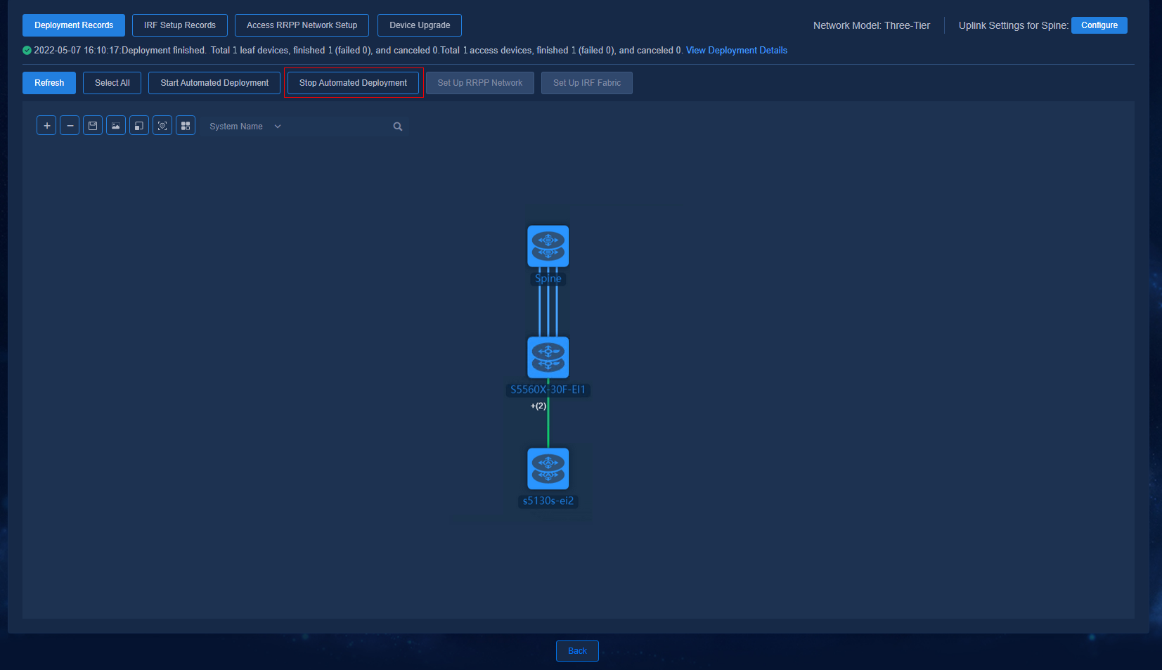
When all or part of the devices have been automatically deployed, you can click Stop Automated Deployment to stop the deployment, which forms a closed loop for the deployment process. Clicking Stop Automated Deployment will stop devices from waiting for deployment. It cannot stop the ongoing deployment.
|
|
NOTE: A maximum of 10 devices can be deployed at a time. Clicking Stop Automated Deployment will disable automated deployment for the devices that have not started the automated deployment process. |
Figure 57 Stopping automated deployment
Performing another automated deployment when topology updates
When there is any update to automation topology (modifying links between devices, or adding or deleting device nodes), another automated deployment is required to update the corresponding configuration changes (the devices at both ends of a changed link must be selected).
|
|
NOTE: During automated deployment of access devices, the controller have assigned PVIDs starting from 101 (101 to 3000) to downlink ports. Therefore, when some uplinks of the managed access devices change, it is necessary to clear settings for interfaces of the changed links. The interfaces shall be restored to the default state to ensure that the devices can be connected normally. |
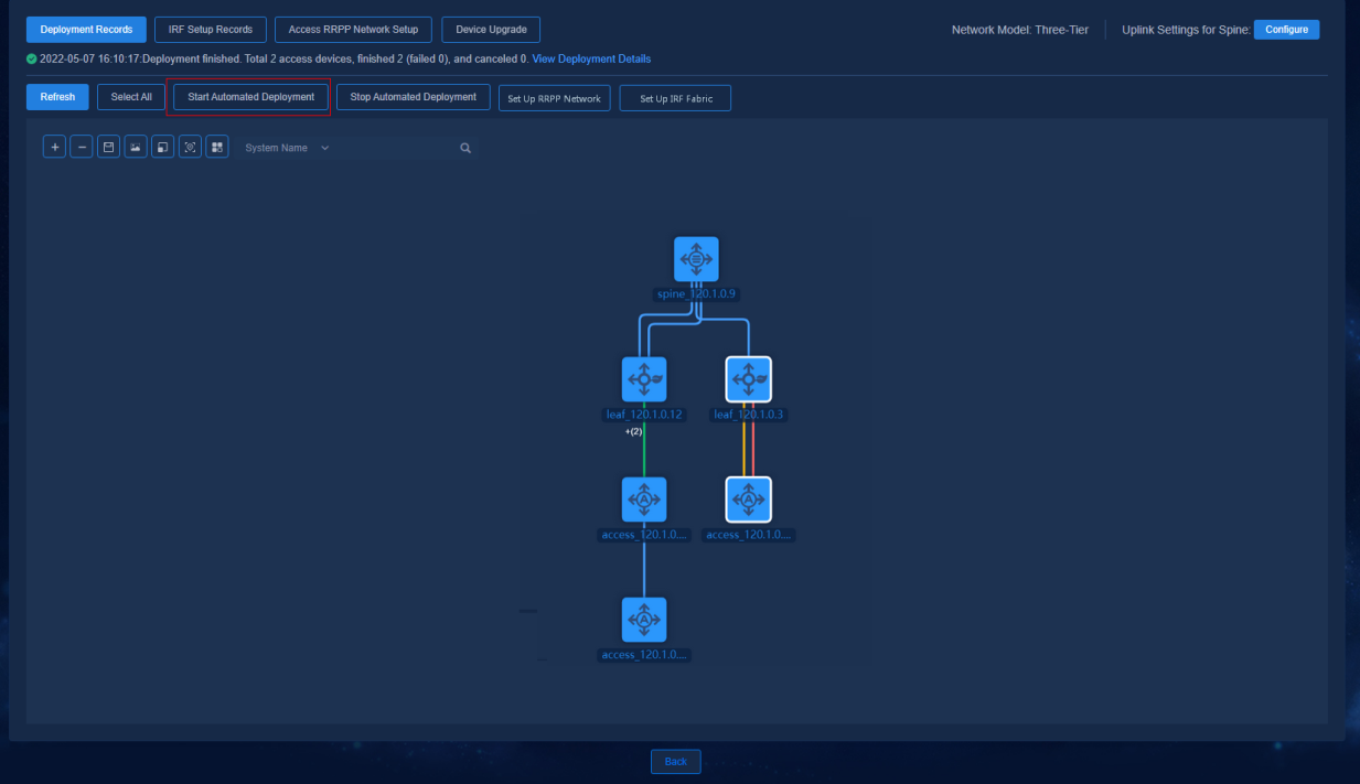
Adding device nodes (for example, adding an access node)
The following example illustrates how to add an access node:
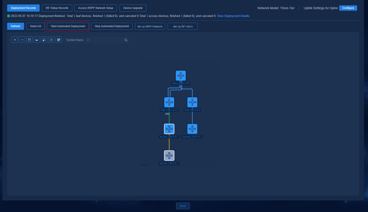
1. Click Refresh to refresh the topology and to discover access devices that are not configured.
Figure 58 Refreshing topology
2. Select a new node and the changed link and node, and click Start Automated Deployment. The controller will automatically deploy relevant configurations to the changed and selected topology nodes and links.
Figure 59 Starting automated deployment
Changing links of managed access devices
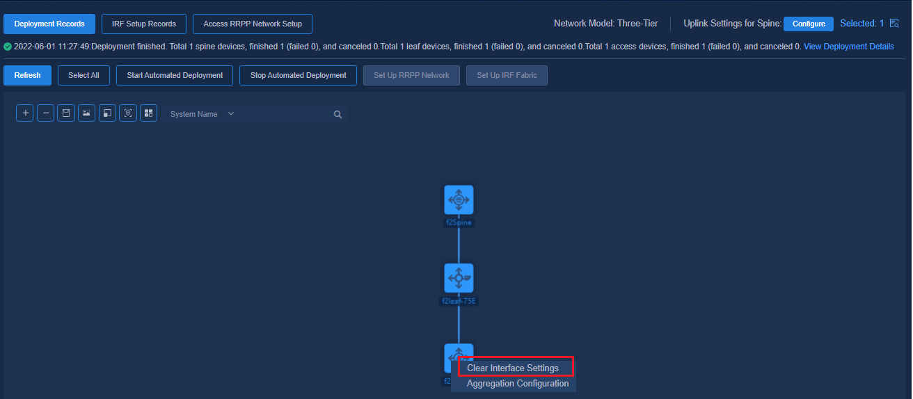
1. Before changing links of access devices, navigate to the Automation > Campus Network > Fabrics > View Topology page and right-click on the access devices that require changing links. Click Clear Interface Settings (only applicable to managed access devices).
To change the link between the leaf device and the level-1 access device, if the access link interface needs to be changed, right-click on the level-1 access device to clear interface settings. To change links between cascaded access devices, clear interface settings for all the interfaces that need change links on the access devices.
Figure 60 Clearing interface settings 1
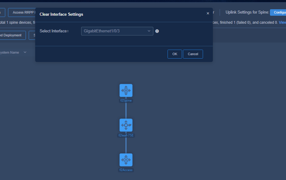
2. Select the interface whose settings need to be cleared and click OK (this interface is the new interface where the changed link is to be connected).
Figure 61 Clearing interface settings 2
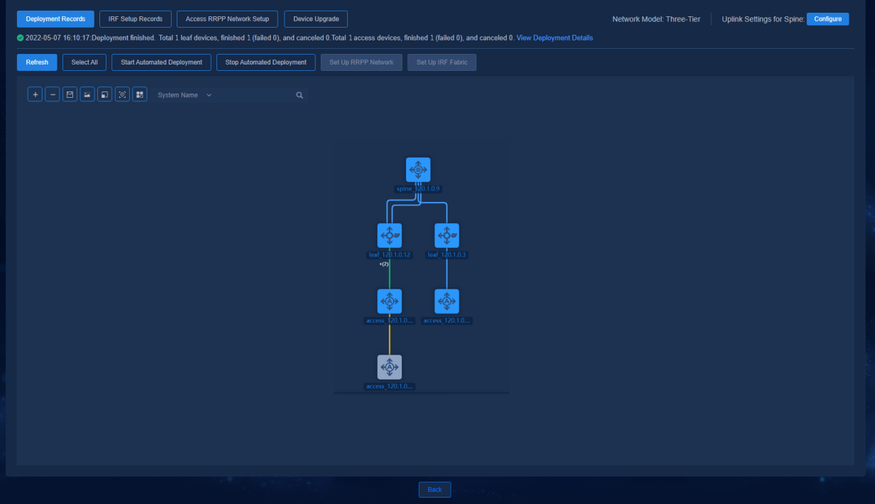
3. Change the device link to connect to the previously configured interface. Click Refresh to refresh the topology and to discover changed links.
Figure 62 Changing links
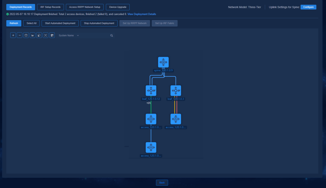
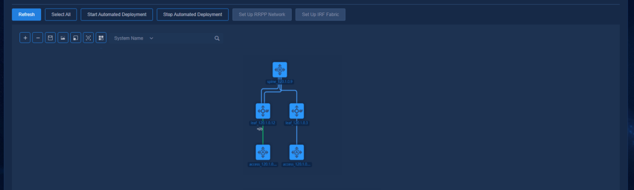
4. Select the changed link and relevant device nodes, and click Start Automated Deployment. Then, the controller will automatically deploy relevant configurations to the changed and selected topology nodes and links. After the topology display is updated, the network becomes a single link network.
Figure 63 Starting automated deployment
Expanding links of managed devices
1. Add device links and click Refresh to refresh the topology and to discover expanded links.
Figure 64 Expanding links
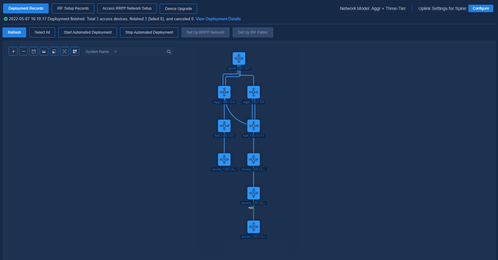
2. Select an expanded link and relevant device nodes, and click Start Automated Deployment. Then, the controller will automatically deploy relevant configurations to the changed and selected topology nodes and links.
Figure 65 Starting automated deployment
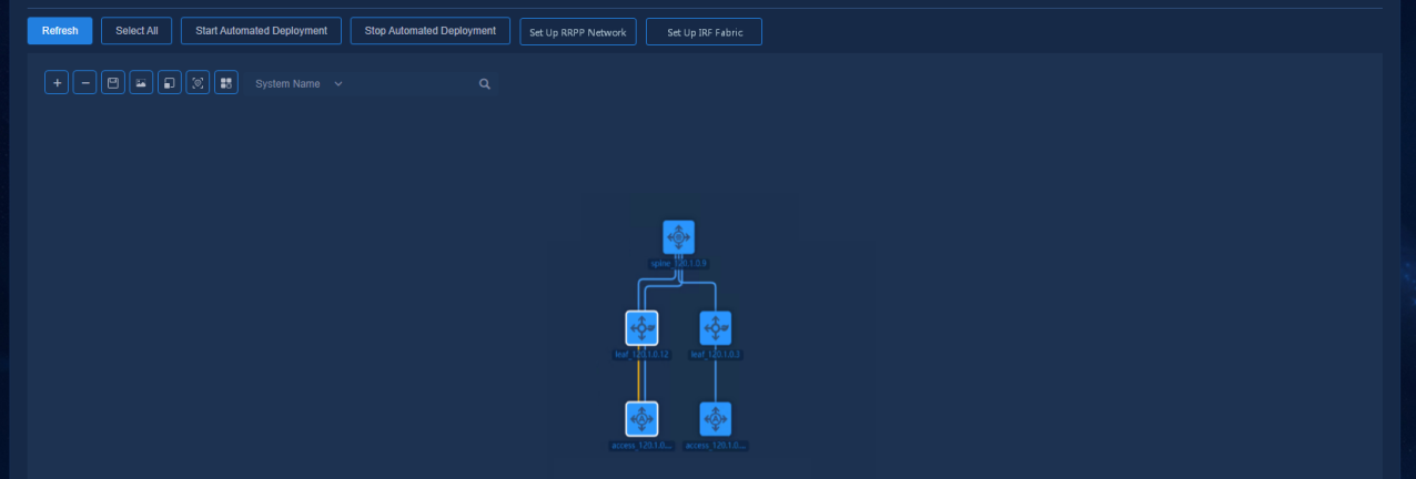
Figure 66 Automated deployment completed
For the expanded links between the leaf tier and the access tier and between multiple access tiers, aggregations are automatically configured; for the expanded links between spine tier and leaf tier, between spine tier and aggr tier, and between aggr tier and leaf tier, ECMP is automatically configured.
Access RRPP ring network
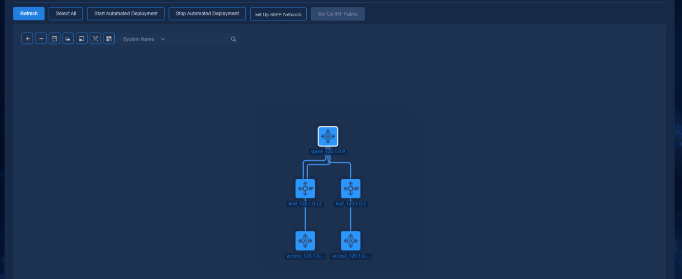
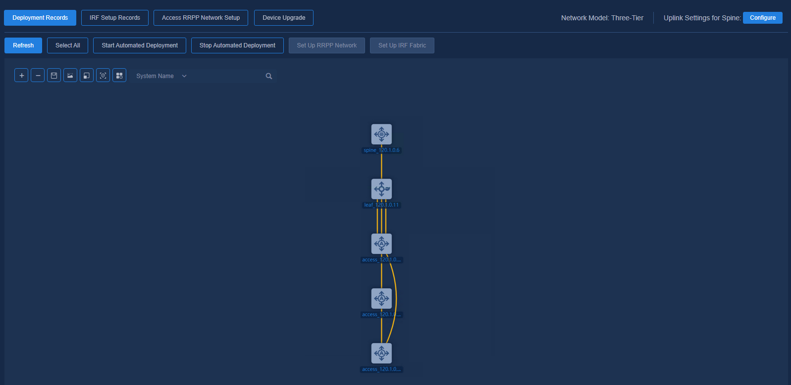
Viewing automated deployment topology
To create an access RRPP ring network, navigate to the Automation > Campus Network > Fabrics > View Topology page and view the topology node information of the device.
Figure 67 Topology
|
|
NOTE: · RRPP rings can only be set up on access devices. · Devices in a ring topology only allow for single links. · Devices in a ring are not allowed to connect to other devices to form a loop. |
Configuring a ring network
Deploying configurations
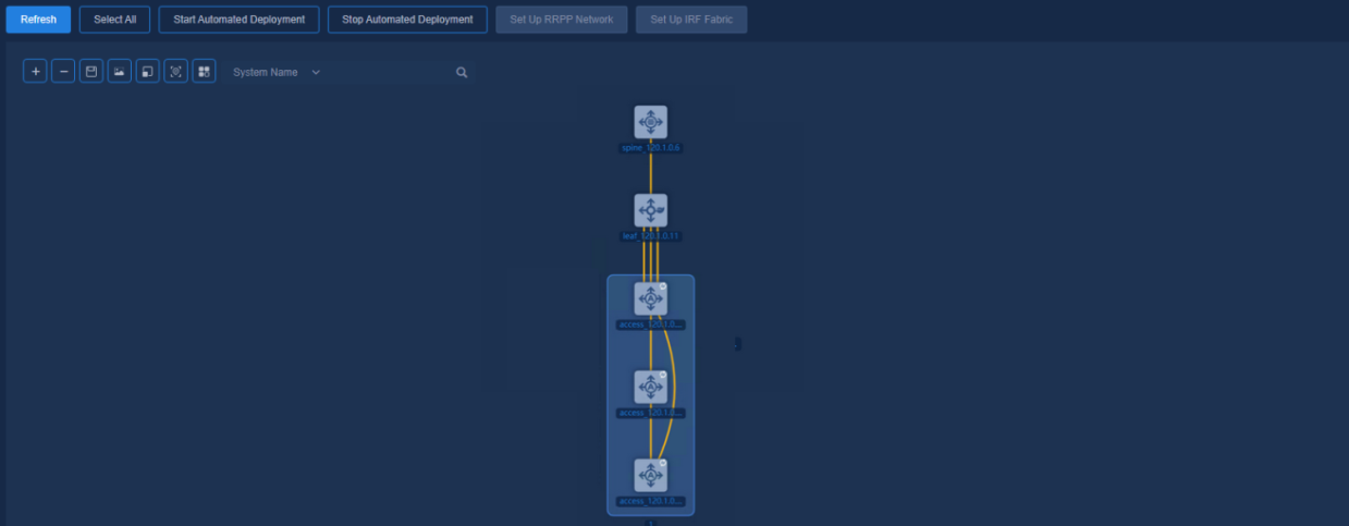
1. Select the access devices to be included in the ring network, and click Set Up RRPP Network. On the pop-up page, enter RRPP Network Name, select Master Node, and configure Primary Port and Secondary Port. Then click OK to apply the settings.
Figure 68 Selecting devices
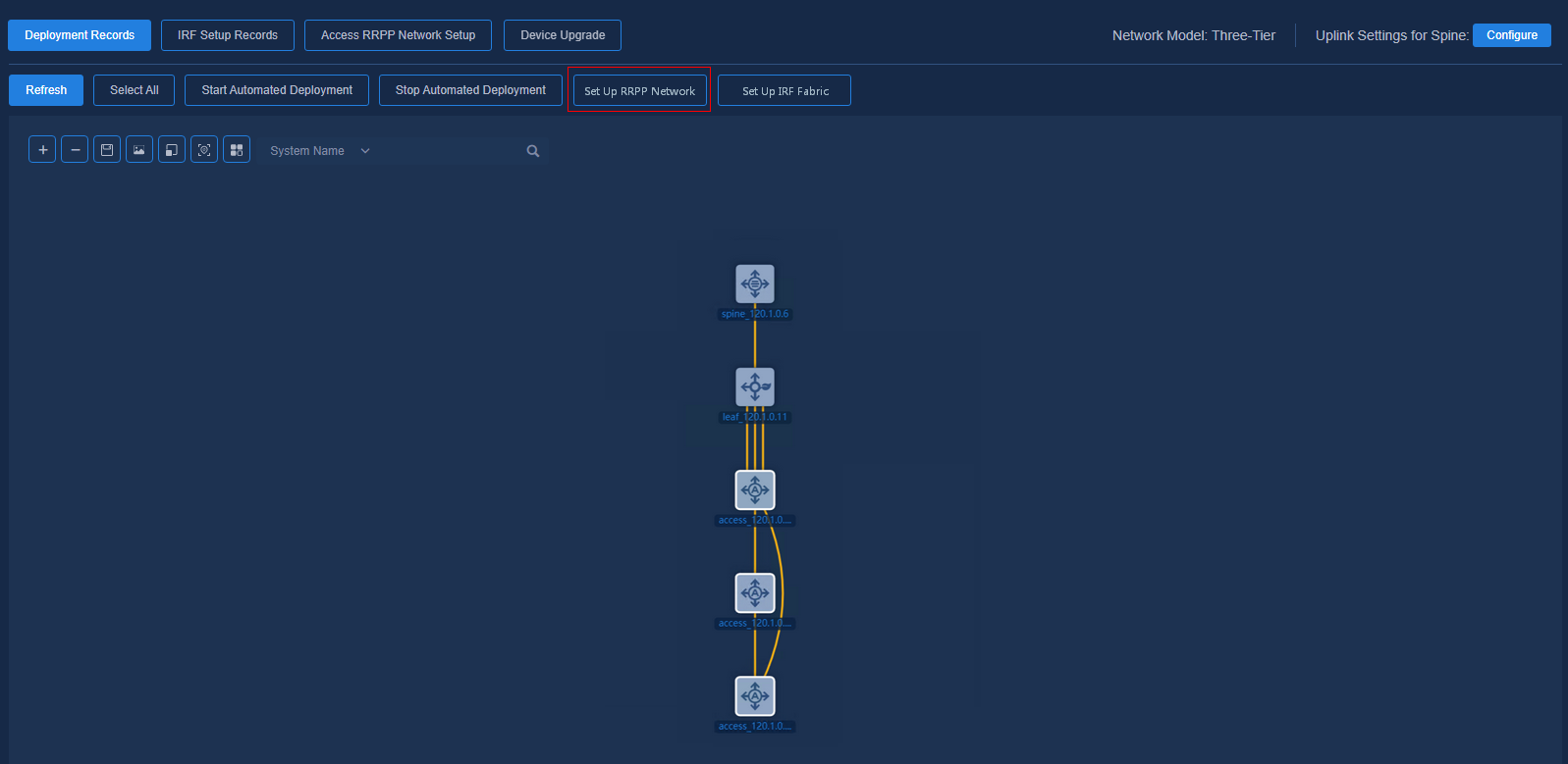
Figure 69 Configuring RRPP ring network
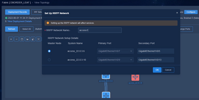
Figure 70 Configurations being deployed
Viewing configuration records
Click ACCESS RRPP Network Setup to view the configuration progress and configuration records.
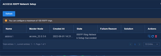
|
|
NOTE: · To change the ring network configurations or adjust its connection lines, you need to delete the original ring network configurations and update the links. After the above operations are completed, you can set up a new ring network. · Setting up the RRPP network will affect services. |
Verifying device configurations
1. Checking main configurations of the leaf device
The leaf device connected to the access RRPP ring network will issue loop detection configuration.
The downlink interface of the leaf device is configured as follows:
[H3C-Ten-GigabitEthernet1/0/27]dis this
#
interface Ten-GigabitEthernet1/0/27
port link-mode bridge
loopback-detection enable vlan 1
loopback-detection action shutdown
#
The other interfaces of the leaf device are configured as follows:
[H3C-Ten-GigabitEthernet1/0/25]dis this
#
interface Ten-GigabitEthernet1/0/25
port link-mode bridge
loopback-detection action shutdown
#
2. Checking main configurations of the access devices
Checking RRPP configurations at the master node
Global configuration:
#
stp region-configuration
instance 1 vlan 1 101 to 4089 4093 to 4094
active region-configuration
#
#
rrpp domain 1
control-vlan 99
protected-vlan reference-instance 1
ring 1 node-mode master primary-port GigabitEthernet1/0/24 secondary-port GigabitEthernet1/0/23 level 0
ring 1 enable
#
rrpp enable
#
Configuration on the interconnect interfaces of the RRPP network:
[H3C-GigabitEthernet1/0/24]dis this
#
interface GigabitEthernet1/0/24
port link-mode bridge
port link-type trunk
port trunk permit vlan 1 to 99 101 to 4094
undo stp enable
#
Checking RRPP configurations at a transit node
Global configuration:
#
stp region-configuration
instance 1 vlan 1 101 to 4089 4093 to 4094
active region-configuration
#
rrpp domain 1
control-vlan 99
protected-vlan reference-instance 1
ring 1 node-mode transit primary-port GigabitEthernet1/0/37 secondary-port Ten-GigabitEthernet1/0/49 level 0
ring 1 enable
#
rrpp enable
#
Configuration on the interconnect interfaces of the RRPP network:
[H3C-GigabitEthernet1/0/37]dis this
#
interface GigabitEthernet1/0/37
port link-type trunk
port trunk permit vlan 1 to 99 101 to 4094
undo stp enable
poe enable
#
Viewing the RRPP status
View RRPP configurations at the master node. The output shows that the secondary port is blocked.
<H3C>display rrpp verbose domain 1
Domain ID : 1
Control VLAN : Primary 99, Secondary 100
Protected VLAN: Reference instance 1
Hello timer : 1 sec, Fail timer: 3 sec
Linkup-Delay timer: 0 sec
Fast detection status: Disabled
Fast-Hello timer: 20 ms, Fast-Fail timer: 60 ms
Fast-Edge-Hello timer: 10 ms, Fast-Edge-Fail timer: 30 ms
Ring ID : 1
Ring level : 0
Node mode : Master
Ring state : Complete
Enable status : Yes, Active status: Yes
Primary port : GE1/0/24 Port status: UP
Secondary port: GE1/0/23 Port status: BLOCKED
View RRPP configurations at the transit node. No ports are blocked.
<H3C>display rrpp verbose domain 1
Domain ID : 1
Control VLAN : Primary 99, Secondary 100
Protected VLAN: Reference instance 1
Hello timer : 1 sec, Fail timer: 3 sec
Linkup-Delay timer: 0 sec
Ring ID : 1
Ring level : 0
Node mode : Transit
Ring state : LinkUp
Enable status : Yes, Active status: Yes
Primary port : GE1/0/37 Port status: UP
Secondary port: XGE1/0/49 Port status: UP
Starting automated deployment
The automated deployment process is similar to that for a three-tier network. For details, see "Starting automated deployment." Devices at the spine, leaf, and access tiers are involved.
Viewing the automated deployment details
Once automated deployment is started for all the devices in the topology, you can view the overall deployment status by using View Deployment Details.
Double-click a specific device node to view the detailed deployment process of the spine/leaf/access device. For details, see the deployment process of a three-tier network.
Viewing the device deployment results
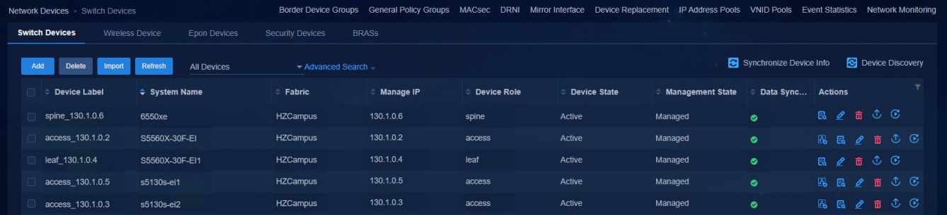
Viewing the status of devices on the controller
Navigate to the Automation > Campus Network > Network Devices page to view the device information. All the automatically deployed devices have been successfully upgraded. Device State is Active. Management State is Managed.
Figure 71 Network devices
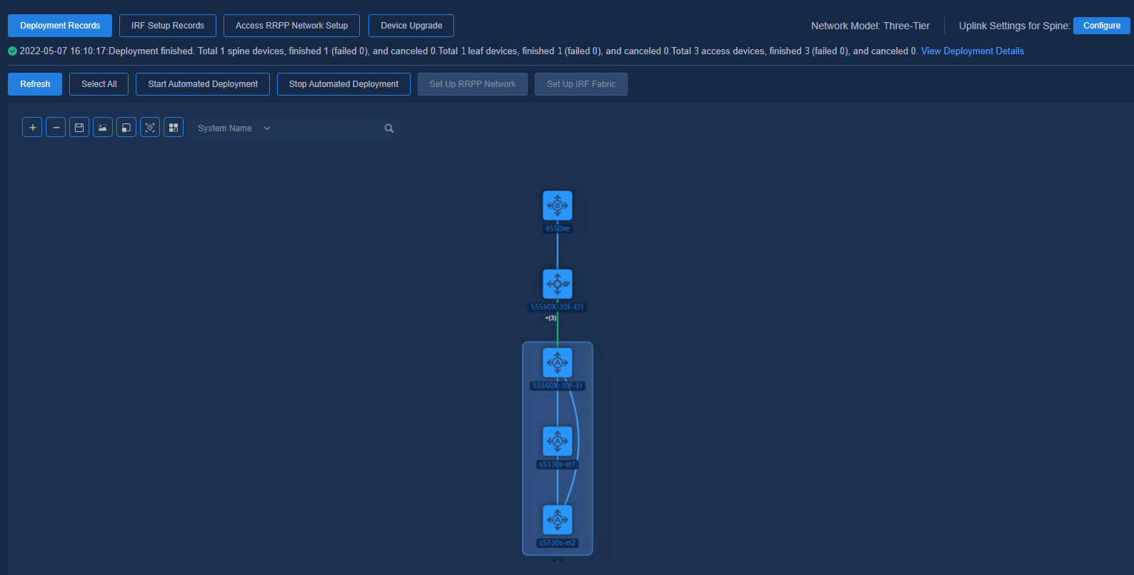
Navigate to the Automation > Campus Network > Fabrics > View Topology page to view the topology node information of the device. The link state has been changed to Configured.
Figure 72 Topology
Verifying main configurations of devices
See section Viewing the device deployment results for configuration of devices at the spine/leaf/access layer. If the leaf device and the ring network devices at the access tier are connected via multiple links, some configurations for aggregate interfaces may vary.
Configurations on the leaf downlink aggregate interface:
[S5560X-30F-EI1-Bridge-Aggregation1024]dis this
#
interface Bridge-Aggregation1024
port link-type trunk
port trunk permit vlan 1 101 to 3000 4094
link-aggregation mode dynamic
stp tc-restriction
loopback-detection enable vlan 1
loopback-detection action shutdown
#
service-instance 4094
encapsulation s-vid 4094
xconnect vsi vxlan4094
#
Configurations on the leaf downlink aggregation member ports:
[S5560X-30F-EI1-Ten-GigabitEthernet1/0/27]dis this
#
interface Ten-GigabitEthernet1/0/27
port link-mode bridge
port link-type trunk
port trunk permit vlan 1 101 to 3000 4094
port link-aggregation group 1024
loopback-detection enable vlan 1
loopback-detection action shutdown
Changing uplink AC interface
Changing uplink interface before automated deployment
If you wish to change or aggregate the uplink interface before starting the automated deployment, re-select an uplink interface and then start the automated deployment. (Before starting automated deployment, selecting an uplink interface will not deliver the configurations.)
1. Navigate to the Automation > Campus Network > Fabrics > View Topology page to view the topology node information of the device.
2. Select the uplink interface of the spine/single-leaf device.
Changing uplink interface after automated deployment
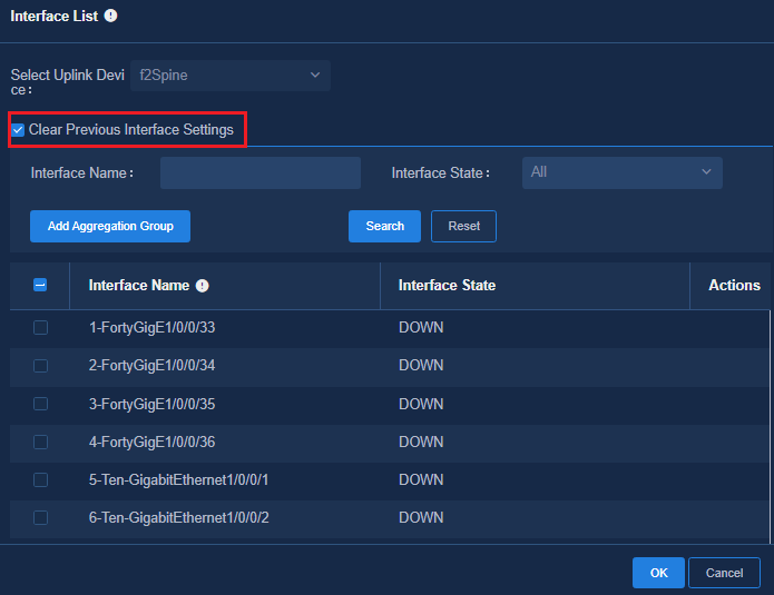
After the automated device deployment is completed, if you wish to change or aggregate the uplink interface, you need to re-select an uplink interface. At this time, you can select whether to check Clear Previous Interface Settings.
If the item is checked (recommended), previous interface settings will be cleared, and configuration commands will be delivered to the newly selected uplink interface.
If the item is unchecked, previous interface settings will not be cleared, and configuration commands will be delivered to the newly selected uplink interface.
The configuration of changing the uplink interface after the device has been successfully deployed will be delivered in real time. You do not need to start another automated deployment in this case.
Figure 73 Changing the uplink interface
Cascading of access devices
The access device directly connected to the leaf device is called the level-1 access device, and the level-1 access device is connected to the level-2 access device, and so on. The current version supports up to three levels of access device cascading. The automated deployment process of the level-2 access device is similar to that of the level-1 access device.
|
|
NOTE: When a level-1 device is deployed, its downlink ports are assigned PVIDs in the range of 101 to 3000. When a downlink port on the device comes up, its PVID changes to 1 if the port connects to an H3C switch. This change ensures automatic deployment of the lower-level access device (the controller processes the PVIDs only for access ports not for trunk/hybrid ports). If the level-1 device is not an H3C device, you must manually change the PVID of the downlink port to 1. |
Level-2/Level-3 devices start automated deployment with empty configuration
1. After connecting the level-2 and level-3 devices, view the topology and start automated deployment of cascaded access devices.
Figure 74 Automated deployment of cascaded access devices
2. Once all the cascaded access devices have completed automated deployment, you can view the overall deployment by navigating to the View Deployment Details page.
3. Double-click an access device node to view the deployment details of the access device.
Viewing the devices and the deployment result
Viewing the status of devices connected to the controller
Navigate to the Automation > Campus Network > Network Devices page to view the device information. All the cascaded access devices have been automatically deployed. Device State is Active.
Figure 75 Network devices
Navigate to the Automation > Campus Network > Fabrics > View Topology page to view the topology node information. The link state has been changed to Configured.
Figure 76 Topology
Checking main configurations of the cascaded access devices
The cascaded access devices have obtained IP addresses of VLAN 1 and VLAN 4094, respectively.
<access7>display interface brief | in UP
InLoop0 UP UP(s) --
NULL0 UP UP(s) --
Vlan1 UP UP 120.1.0.9
Vlan4094 UP UP 130.1.0.23
GE1/0/43 UP 1G(a) F(a) T 1
Configuration on the interconnect interfaces of the cascaded access devices:
interface GigabitEthernet1/0/43
port link-type trunk
port trunk permit vlan 1 to 99 101 to 4094
poe enable
IRF stacking
With the optimized automation, the spine/leaf/access devices can be deployed as standalone devices or as an IRF fabric. To deploy an IRF fabric, as a best practice, configure the IRF fabric for the devices before starting the automated deployment for the devices. The devices can be expanded and the links can be expanded or changed after the automated deployment.
|
|
NOTE: · The stacked switches must be of the same model, version, and role. · The spine/leaf tier only allows stacking of two devices. The access tier allows stacking of nine devices. · Each IRF member device needs to be connected to its upstream device. · Between two devices it allows more than one IRF port but only one MAD detection interface. · If you wish to expand the capacity of the stacked devices, you can select one of them for expansion. · The devices that have formed a ring stack cannot be expanded. · You are not allowed to stack two or more managed devices. If you need to do so, you have to clear device settings and deploy the devices again. |
Onboarding a spine/single-leaf IRF fabric
To onboard a spine/single-leaf IRF fabric, perform the steps below:
1. Use one cable to connect the spine/single-leaf device and Layer 3 switch.
2. Start up the devices with empty configuration and the devices obtain the VLAN 1 address and actively establish WebSocket connections with the controller.
3. Set up the IRF fabric on the automation topology page.
4. Configure the uplink interface aggregation.
5. Manually configure downlink interface aggregation on the Layer 3 switch.
6. On the automation topology page, select a configured aggregate interface as the uplink interface.
7. Start automated device deployment.
Connecting devices and starting up the spine/single-leaf devices with empty configuration
Figure 77 Starting up with no configuration
Selecting devices to set up an IRF fabric
Navigate to the Automation > Campus Network > Fabrics > View Topology page to view the topology node information. There exist connection lines between two spine devices.
Figure 78 Topology
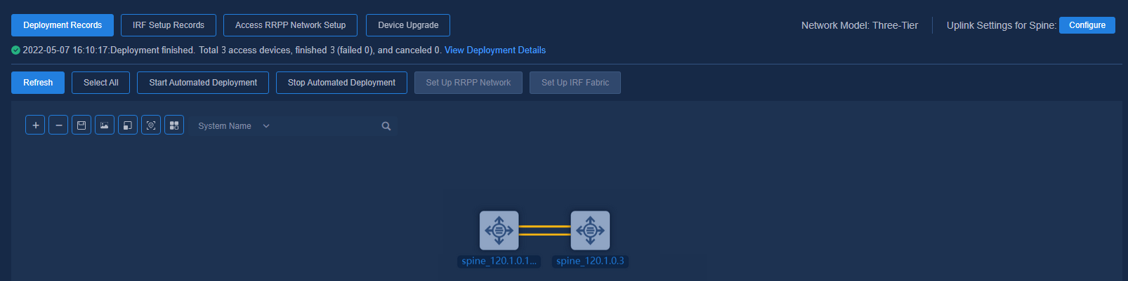
Select two spine devices and click Set Up IRF Fabric. Specify the master device, select the corresponding IRF port and MAD interface, and then click OK. At this time, devices start automatic IRF stacking. Wait for some time and then view the stacking result.
IRF setup records
Click IRF Setup Records to check the IRF stacking progress or view the IRF configuration.
Checking IRF stacking result
On the automation topology page, the two
selected spine devices have been stacked successfully into an IRF fabric. The
device topology nodes are merged into one device. The icons of the two device
nodes have been merged into one new icon ![]() .
.
Figure 79 IRF setup result
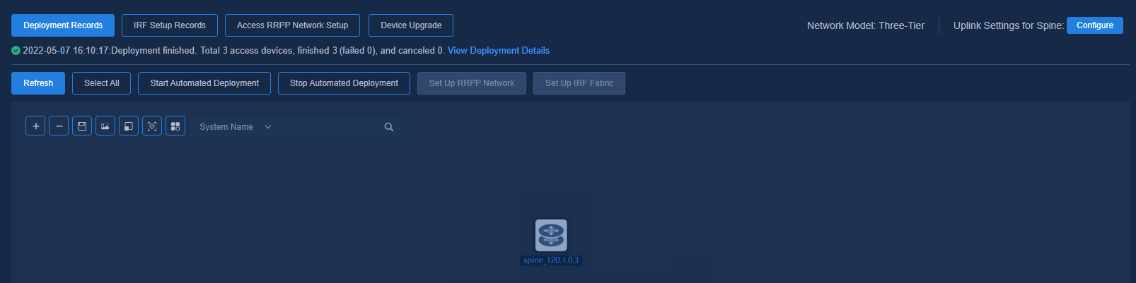
The IRF fabric is configured correctly.
<H3C>display irf
MemberID Role Priority CPU-Mac Description
1 Standby 16 00e0-fc0f-8c02 ---
*+2 Master 17 00e0-fc0f-8c03 ---
--------------------------------------------------
* indicates the device is the master.
+ indicates the device through which the user logs in.
The bridge MAC of the IRF is: 943b-b0bb-7e32
Auto upgrade : yes
Mac persistent : always
Domain ID : 0
The MAD is configured correctly.
<H3C>display mad verbose
Multi-active recovery state: No
Excluded ports (user-configured):
Excluded ports (system-configured):
IRF physical interfaces:
Twenty-FiveGigE1/0/1
Twenty-FiveGigE2/0/1
BFD MAD interfaces:
Vlan-interface100
MAD ARP disabled.
MAD ND disabled.
MAD LACP disabled.
MAD BFD enabled interface: Vlan-interface100
MAD status : Normal
Member ID MAD IP address Neighbor MAD status
1 192.168.100.1/24 2 Normal
2 192.168.100.2/24 1 Normal
Starting automated deployment of the IRF fabric and viewing the deployment result
Before starting automated deployment for the spine IRF fabric, you need to configure the uplink interface aggregation for the spine devices and manually configure aggregation at the interconnect interfaces of the peer Layer 3 switch, and then select a configured aggregate interface as the uplink interface.
Select the stacked devices and click Start Automated Deployment.
Navigate to the Automation > Campus Network > Network Devices page to view the device information. The spine IRF fabric has been automatically deployed. Device State is Active.
Figure 80 Network devices
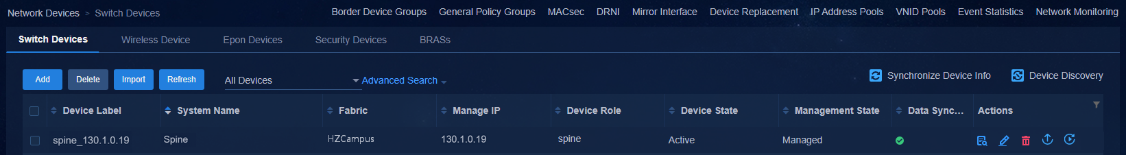
Onboarding a leaf IRF fabric
To onboard a leaf IRF fabric, perform the steps below:
1. Each IRF member device needs to be connected to its upstream device.
2. Interconnect one leaf device with the other one.
3. Start up the devices with empty configuration and the devices obtain the VLAN 1 address and actively establish WebSocket connections with the controller.
4. Set up an IRF fabric for the devices on the automation topology page.
5. Start automated deployment of the IRF fabric.
Connecting devices and starting up the leaf devices with empty configuration
Figure 81 Starting up with no configuration
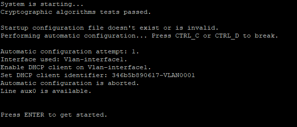
Selecting devices to set up an IRF fabric
Navigate to the Automation > Campus Network > Fabrics > View Topology page to view the topology node information.
Figure 82 Topology
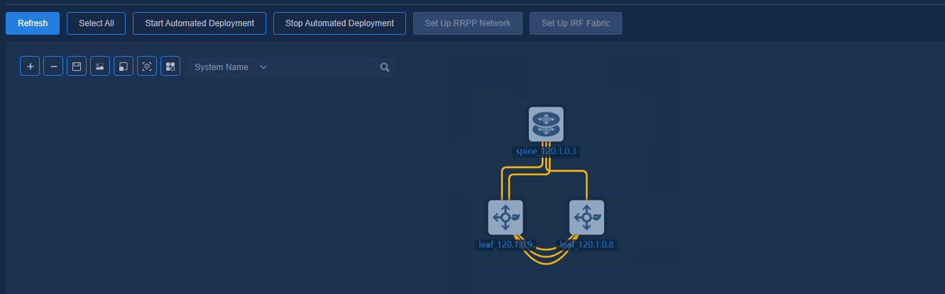
Select two leaf devices and click Set Up IRF Fabric. Specify the master device, select the corresponding IRF port and MAD interface, and then click OK. At this time, devices start automatic IRF stacking. Wait for some time and then view the stacking result.
IRF setup records
Click IRF Setup Records to view the device stacking progress in real time.
Checking the IRF stacking result
On the automation topology page, the two
selected leaf devices have been stacked successfully into an IRF fabric. The
device topology nodes are merged into one device. The icons of the device nodes
have been merged into one new icon ![]() .
.
Figure 83 Topology

The IRF fabric is configured correctly.
<H3C>display irf
MemberID Role Priority CPU-Mac Description
*1 Master 17 f010-90db-7402 ---
+2 Standby 15 f010-90db-7403 ---
--------------------------------------------------
* indicates the device is the master.
+ indicates the device through which the user logs in.
The bridge MAC of the IRF is: 346b-5b89-0617
Auto upgrade : yes
Mac persistent : always
Domain ID : 0
The MAD is configured correctly.
<H3C>display mad verbose
Multi-active recovery state: No
Excluded ports (user-configured):
Excluded ports (system-configured):
IRF physical interfaces:
Ten-GigabitEthernet1/0/26
Ten-GigabitEthernet1/0/27
Ten-GigabitEthernet2/0/26
Ten-GigabitEthernet2/0/27
BFD MAD interfaces:
Vlan-interface100
MAD ARP disabled.
MAD ND disabled.
MAD LACP disabled.
MAD BFD enabled interface: Vlan-interface100
MAD status : Normal
Member ID MAD IP address Neighbor MAD status
1 192.168.100.1/24 2 Normal
2 192.168.100.2/24 1 Normal
Starting automated deployment of the leaf IRF fabric and viewing the deployment result
Select the stacked devices and click Start Automated Deployment. Once the device has been automatically deployed, double-click the stacked device node to view the deployment details of the stacked device.
Navigate to the Automation > Campus Network > Network Devices page to view the device information. The leaf IRF fabric has been automatically deployed. Device State is Active.
Figure 84 Network devices
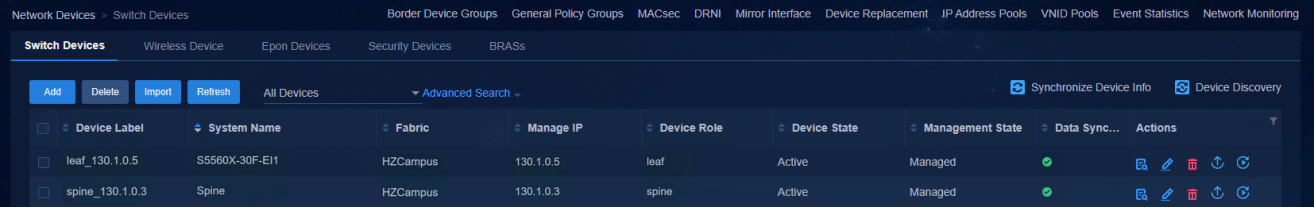
Onboarding an access IRF fabric
To onboard an access IRF fabric, perform the steps below:
1. Each IRF member device needs to be connected to its upstream device.
2. Interconnect one device with the other one.
3. Start up the devices with empty configuration and the devices obtain the VLAN 1 address and actively establish WebSocket connections with the controller.
4. Set up an IRF fabric for the devices on the automation topology page.
5. Start automated deployment of the IRF fabric.
Connecting devices and starting up the access devices with empty configuration
Figure 85 Starting up with empty configuration
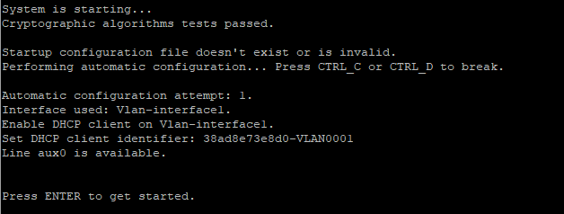
Selecting devices to set up an IRF fabric
Navigate to the Automation > Campus Network > Fabrics > View Topology page to view the topology node information.
Figure 86 Topology
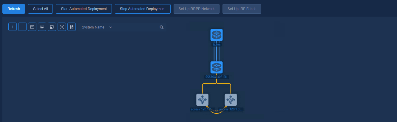
Select two access devices and click Set Up IRF Fabric. Specify the master device, select the corresponding IRF port and MAD interface, and then click OK. At this time, devices start automatic IRF stacking. Wait for some time and then view the stacking result.
IRF setup records
Click IRF Setup Records to view the device stacking progress in real time.
Checking IRF stacking result
On the automation topology page, the two
selected access devices have been stacked successfully into an IRF fabric. The
device topology nodes are merged into one device. The icons of the device nodes
have been merged into one new icon ![]() .
.
Figure 87 IRF setup result
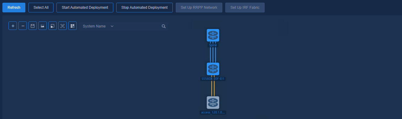
The IRF fabric is configured correctly.
<H3C>display irf
MemberID Role Priority CPU-Mac Description
*+1 Master 17 f010-90db-7402 ---
2 Standby 15 f010-90db-7403 ---
--------------------------------------------------
* indicates the device is the master.
+ indicates the device through which the user logs in.
The bridge MAC of the IRF is: 38ad-8e73-e8d0
Auto upgrade : yes
Mac persistent : always
Domain ID : 0
The MAD is configured correctly.
<H3C>display mad verbose
Multi-active recovery state: No
Excluded ports (user-configured):
Excluded ports (system-configured):
IRF physical interfaces:
Ten-GigabitEthernet1/0/49
Ten-GigabitEthernet2/0/49
BFD MAD interfaces:
GigabitEthernet1/0/43
GigabitEthernet2/0/43
Vlan-interface100
MAD ARP disabled.
MAD ND disabled.
MAD LACP disabled.
MAD BFD enabled interface: Vlan-interface100
MAD status : Normal
Member ID MAD IP address Neighbor MAD status
1 192.168.100.1/24 2 Normal
2 192.168.100.2/24 1 Normal
Starting automated deployment of the access IRF fabric and viewing the deployment result
Select the stacked devices and click Start Automated Deployment. Once the device has been automatically deployed, double-click the stacked device node to view the deployment details of the stacked device.
Navigate to the Automation > Campus Network > Network Devices page to view the device information. The access IRF fabric has been automatically deployed. Device State is Active.
Figure 88 Network devices
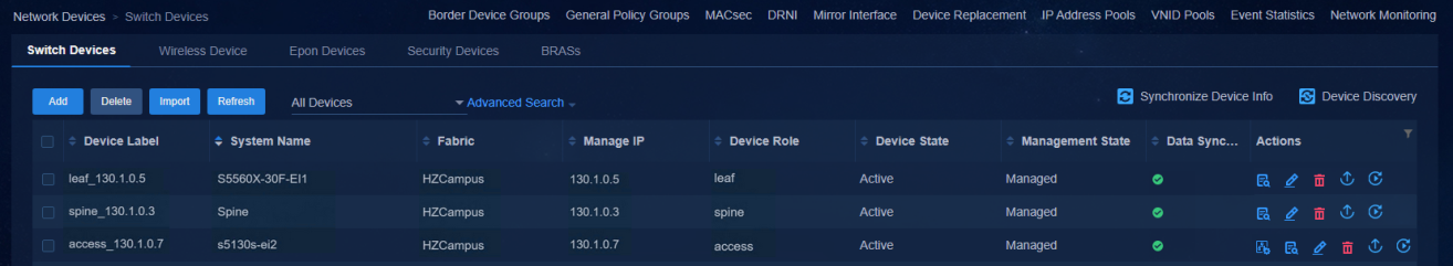
Expanding the IRF links
Devices in an IRF fabric can add IRF links if required.
Adding device links
Select the device to be expanded and add a new physical link.
Selecting devices to configure IRF fabric
Navigate to the Automation > Campus Network > Fabrics > View Topology page to view the topology node information.
Figure 89 Topology
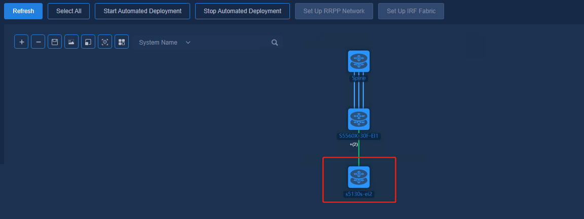
Select a stacked device (here an access device is selected for illustration) and click Set Up IRF Fabric to display the current IRF configuration by default.
Modify the IRF configuration as required. In this example, add a pair of interfaces of the newly connected link to the IRF port and click OK. Wait for some time and view the IRF stacking result.
IRF setup records
Click IRF Setup Records to view the device stacking progress in real time.
Checking IRF stacking result
The IRF fabric is configured correctly.
<s5130s-ei2>display irf
MemberID Role Priority CPU-Mac Description
*+1 Master 17 f010-90db-7402 ---
2 Standby 15 f010-90db-7403 ---
--------------------------------------------------
* indicates the device is the master.
+ indicates the device through which the user logs in.
The bridge MAC of the IRF is: 38ad-8e73-e8d0
Auto upgrade : yes
Mac persistent : always
Domain ID : 0
The MAD is configured correctly.
<s5130s-ei2>display mad verbose
Multi-active recovery state: No
Excluded ports (user-configured):
Excluded ports (system-configured):
IRF physical interfaces:
Ten-GigabitEthernet1/0/49
Ten-GigabitEthernet1/0/50
Ten-GigabitEthernet2/0/49
Ten-GigabitEthernet2/0/50
BFD MAD interfaces:
GigabitEthernet1/0/43
GigabitEthernet2/0/43
Vlan-interface100
MAD ARP disabled.
MAD ND disabled.
MAD LACP disabled.
MAD BFD enabled interface: Vlan-interface100
MAD status : Normal
Member ID MAD IP address Neighbor MAD status
1 192.168.100.1/24 2 Normal
2 192.168.100.2/24 1 Normal
Changing IRF links
Change the links of stacked devices if required.
Adding device links
Select the stacked device for which the link is to be changed and add a new physical IRF/MAD link.
|
|
NOTE: · If only one IRF link exists, it is not allowed to change the IRF port. · To change the IRF port at one end, you need first to remove the link and then add the link. |
Selecting devices to configure IRF fabric
Navigate to the Automation > Campus Network > Fabrics > View Topology page to view the topology node information.
Figure 90 Topology
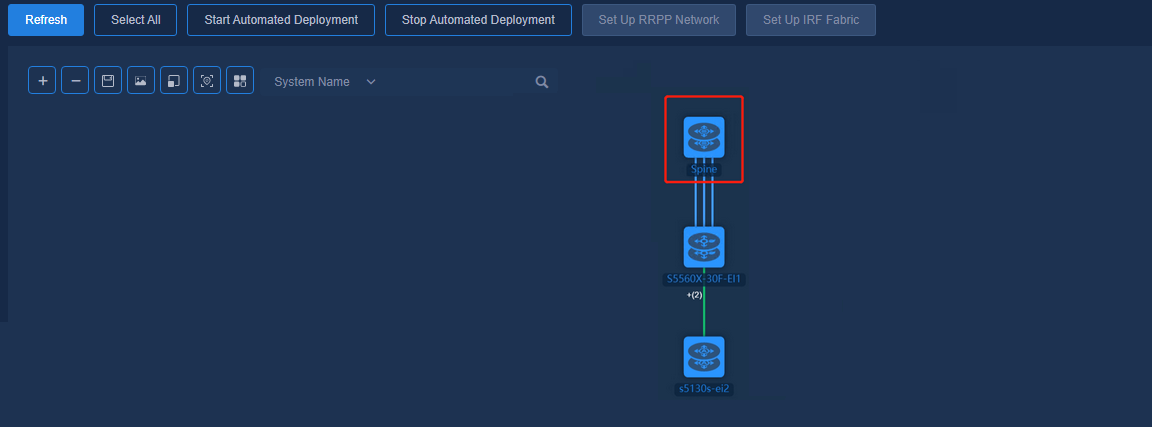
Select the stacked device (here a spine device is selected for illustration) and click Set Up IRF Fabric to display the current IRF configuration by default.
Modify the IRF configuration as required. In this example, change the pair of interfaces of the IRF port and click OK. Wait for some time and view the stacking result.
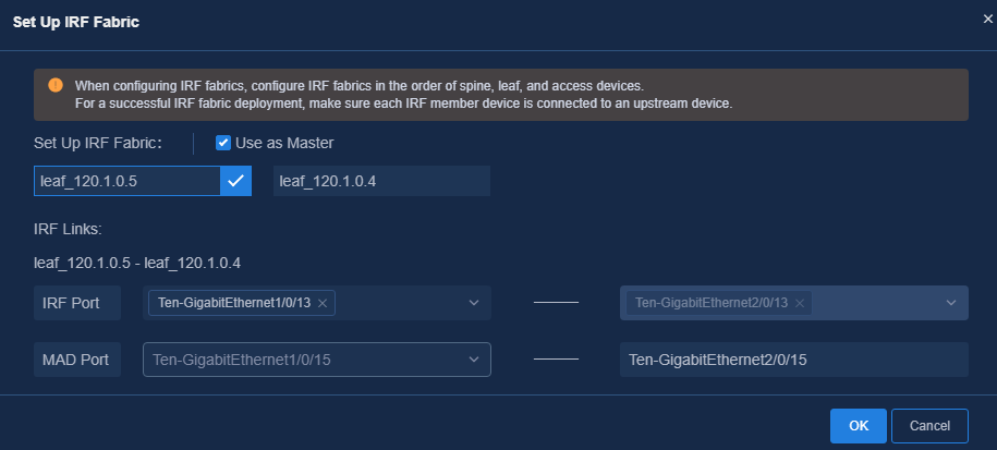
IRF setup records
Click IRF Setup Records to view the device IRF stacking progress in real time.
Figure 91 Stacking configuration records
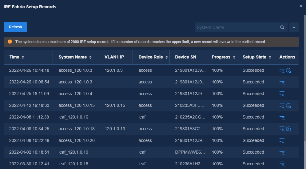
Figure 92 Viewing the IRF stacking progress

Figure 93 Viewing the stacking configuration

Checking IRF stacking result
The IRF fabric is configured correctly.
<Spine>display irf
MemberID Role Priority CPU-Mac Description
*+1 Master 17 00e0-fc0f-8c02 ---
2 Standby 15 00e0-fc0f-8c03 ---
--------------------------------------------------
* indicates the device is the master.
+ indicates the device through which the user logs in.
The bridge MAC of the IRF is: 943b-b0bb-7c8a
Auto upgrade : yes
Mac persistent : always
Domain ID : 0
The MAD is configured correctly.
<Spine>display mad verbose
Multi-active recovery state: No
Excluded ports (user-configured):
Excluded ports (system-configured):
IRF physical interfaces:
Twenty-FiveGigE1/0/1
Twenty-FiveGigE1/0/23
Twenty-FiveGigE2/0/1
Twenty-FiveGigE2/0/23
BFD MAD interfaces:
Vlan-interface100
MAD ARP disabled.
MAD ND disabled.
MAD LACP disabled.
MAD BFD enabled interface: Vlan-interface100
MAD status : Normal
Member ID MAD IP address Neighbor MAD status
1 192.168.100.1/24 2 Normal
2 192.168.100.2/24 1 Normal
O&M monitoring
For details, see AD-Campus Operations Monitoring Deployment Guide.
Appendix – Configuration deployed after optimized automation
Spine device configuration
<Spine>display current-configuration
#
version 7.1.070, ESS 6110L01
#
sysname Spine
#
clock timezone beijing add 08:00:00
#
ip vpn-instance vpn-default
route-distinguisher 1:1
vpn-target 1:1 import-extcommunity
vpn-target 1:1 export-extcommunity
#
address-family evpn
vpn-target 1:1 import-extcommunity
vpn-target 1:1 export-extcommunity
#
telnet server enable
#
irf mac-address persistent timer
irf auto-update enable
undo irf link-delay
irf member 1 priority 1
#
vxlan tunnel mac-learning disable
#
ospf 1
non-stop-routing
area 0.0.0.0
#
lldp global enable
#
password-recovery enable
#
vlan 1
#
vlan 3001 to 3003
#
vlan 4094
#
microsegment enable
#
openflow instance 1
default table-miss permit
description SDN_INSTANCE_27e6331d-746e-48c5-9757-c5a9ee3ad6cb
permit-port-type member-port
flow-table mac-ip 0 extensibility 1
classification global
controller 1 address ip 110.1.0.102 local address ip 130.1.0.12 vrf vpn-default
controller 2 address ip 110.1.0.103 local address ip 130.1.0.12 vrf vpn-default
active instance
#
stp instance 0 priority 0
stp ignored vlan 2 to 4094
stp global enable
#
policy-based-route SDN_GLOBAL_SC permit node 0
if-match acl name SDN_ACL_SC_DEFAULT_NO_EPG
#
ipv6 policy-based-route SDN_GLOBAL_SC permit node 0
if-match acl name SDN_ACL_SC_DEFAULT_NO_EPG
#
l2vpn enable
vxlan tunnel arp-learning disable
vxlan tunnel nd-learning disable
#
vsi vxlan4094
gateway vsi-interface 4094
vxlan 4094
evpn encapsulation vxlan
mac-advertising disable
arp mac-learning disable
nd mac-learning disable
route-distinguisher auto
vpn-target auto export-extcommunity
vpn-target auto import-extcommunity
#
interface Bridge-Aggregation1
port link-type trunk
port trunk permit vlan all
link-aggregation mode dynamic
#
service-instance 4094
encapsulation s-vid 4094
xconnect vsi vxlan4094
#
interface NULL0
#
interface LoopBack0
ip address 200.1.1.2 255,255,255,255
#
interface Vlan-interface1
ip address 120.1.0.9 255.255.255.0
dhcp client identifier ascii 943bb0bb7c8a-VLAN0001
#
interface Vlan-interface3001
ip address unnumbered interface LoopBack0
ospf network-type p2p
ospf 1 area 0.0.0.0
#
interface Vlan-interface3002
ip address unnumbered interface LoopBack0
ospf network-type p2p
ospf 1 area 0.0.0.0
#
interface Vlan-interface3003
ip address unnumbered interface LoopBack0
ospf network-type p2p
ospf 1 area 0.0.0.0
#
interface GigabitEthernet1/0/57
port link-mode bridge
#
interface HundredGigE1/0/25
port link-mode bridge
#
interface HundredGigE1/0/26
port link-mode bridge
#
interface HundredGigE1/0/27
port link-mode bridge
#
interface HundredGigE1/0/28
port link-mode bridge
#
interface HundredGigE1/0/29
port link-mode bridge
#
interface HundredGigE1/0/30
port link-mode bridge
#
interface HundredGigE1/0/31
port link-mode bridge
#
interface HundredGigE1/0/32
port link-mode bridge
#
interface M-GigabitEthernet0/0/0
#
interface M-GigabitEthernet0/0/1
#
interface Vsi-interface4092
description SDN_VRF_VSI_Interface_4092
ip binding vpn-instance vpn-default
ip address unnumbered interface Vsi-interface4094
l3-vni 4092
#
interface Vsi-interface4094
ip binding vpn-instance vpn-default
ip address 130.1.0.12 255.255.255.0
local-proxy-arp enable
#
interface Twenty-FiveGigE1/0/1
port link-mode bridge
#
interface Twenty-FiveGigE1/0/2
port link-mode bridge
#
interface Twenty-FiveGigE1/0/3
port link-mode bridge
port link-type trunk
port trunk permit vlan all
port link-aggregation group 1
#
interface Twenty-FiveGigE1/0/4
port link-mode bridge
port link-type trunk
port trunk permit vlan all
port link-aggregation group 1
#
interface Twenty-FiveGigE1/0/5
port link-mode bridge
#
interface Twenty-FiveGigE1/0/6
port link-mode bridge
#
interface Twenty-FiveGigE1/0/7
port link-mode bridge
#
interface Twenty-FiveGigE1/0/8
port link-mode bridge
#
interface Twenty-FiveGigE1/0/9
port link-mode bridge
#
interface Twenty-FiveGigE1/0/10
port link-mode bridge
port link-type trunk
port trunk permit vlan 1 3001
lldp source-mac vlan 3001
lldp management-address arp-learning vlan 3001
lldp tlv-enable basic-tlv management-address-tlv interface LoopBack0
#
interface Twenty-FiveGigE1/0/11
port link-mode bridge
#
interface Twenty-FiveGigE1/0/12
port link-mode bridge
#
interface Twenty-FiveGigE1/0/13
port link-mode bridge
port link-type trunk
port trunk permit vlan 1 3003
lldp source-mac vlan 3003
lldp management-address arp-learning vlan 3003
lldp tlv-enable basic-tlv management-address-tlv interface LoopBack0
#
interface Twenty-FiveGigE1/0/14
port link-mode bridge
#
interface Twenty-FiveGigE1/0/15
port link-mode bridge
#
interface Twenty-FiveGigE1/0/16
port link-mode bridge
#
interface Twenty-FiveGigE1/0/17
port link-mode bridge
#
interface Twenty-FiveGigE1/0/18
port link-mode bridge
#
interface Twenty-FiveGigE1/0/19
port link-mode bridge
#
interface Twenty-FiveGigE1/0/20
port link-mode bridge
#
interface Twenty-FiveGigE1/0/21
port link-mode bridge
#
interface Twenty-FiveGigE1/0/22
port link-mode bridge
#
interface Twenty-FiveGigE1/0/23
port link-mode bridge
#
interface Twenty-FiveGigE1/0/24
port link-mode bridge
#
interface Twenty-FiveGigE1/0/33
port link-mode bridge
#
interface Twenty-FiveGigE1/0/34
port link-mode bridge
#
interface Twenty-FiveGigE1/0/35
port link-mode bridge
shutdown
#
interface Twenty-FiveGigE1/0/36
port link-mode bridge
#
interface Twenty-FiveGigE1/0/37
port link-mode bridge
#
interface Twenty-FiveGigE1/0/38
port link-mode bridge
#
interface Twenty-FiveGigE1/0/39
port link-mode bridge
#
interface Twenty-FiveGigE1/0/40
port link-mode bridge
port link-type trunk
port trunk permit vlan 1 3002
lldp source-mac vlan 3002
lldp management-address arp-learning vlan 3002
lldp tlv-enable basic-tlv management-address-tlv interface LoopBack0
#
interface Twenty-FiveGigE1/0/41
port link-mode bridge
#
interface Twenty-FiveGigE1/0/42
port link-mode bridge
#
interface Twenty-FiveGigE1/0/43
port link-mode bridge
#
interface Twenty-FiveGigE1/0/44
port link-mode bridge
#
interface Twenty-FiveGigE1/0/45
port link-mode bridge
shutdown
#
interface Twenty-FiveGigE1/0/46
port link-mode bridge
#
interface Twenty-FiveGigE1/0/47
port link-mode bridge
#
interface Twenty-FiveGigE1/0/48
port link-mode bridge
#
interface Twenty-FiveGigE1/0/49
port link-mode bridge
#
interface Twenty-FiveGigE1/0/50
port link-mode bridge
#
interface Twenty-FiveGigE1/0/51
port link-mode bridge
#
interface Twenty-FiveGigE1/0/52
port link-mode bridge
#
interface Twenty-FiveGigE1/0/53
port link-mode bridge
#
interface Twenty-FiveGigE1/0/54
port link-mode bridge
#
interface Twenty-FiveGigE1/0/55
port link-mode bridge
#
interface Twenty-FiveGigE1/0/56
port link-mode bridge
#
bgp 11
non-stop-routing
router-id 200.1.1.2
peer 200.1.1.1 as-number 11
peer 200.1.1.1 connect-interface LoopBack0
peer 200.1.1.3 as-number 11
peer 200.1.1.3 connect-interface LoopBack0
#
address-family l2vpn evpn
peer 200.1.1.1 enable
peer 200.1.1.1 reflect-client
peer 200.1.1.3 enable
peer 200.1.1.3 reflect-client
#
ip vpn-instance vpn-default
#
address-family ipv4 unicast
import-route direct
import-route static
#
scheduler logfile size 16
#
line class aux
user-role network-admin
#
line class vty
user-role network-operator
#
line aux 0
user-role network-admin
#
line vty 0 63
authentication-mode scheme
user-role network-admin
user-role network-operator
#
ip route-static 100.1.0.0 24 120.1.0.1
ip route-static 110.1.0.0 24 120.1.0.1
ip route-static vpn-instance vpn-default 100.1.0.0 24 130.1.0.1
ip route-static vpn-instance vpn-default 110.1.0.0 24 130.1.0.1
#
info-center loghost 110.1.0.100
#
snmp-agent
snmp-agent local-engineid 800063A280943BB0BB7C8E00000001
snmp-agent community write private
snmp-agent community read public
snmp-agent sys-info version all
snmp-agent target-host trap address udp-domain 100.1.0.100 params securityname public v2c
snmp-agent packet max-size 4096
#
ssh server enable
#
ip global policy-based-route SDN_GLOBAL_SC
#
ipv6 global policy-based-route SDN_GLOBAL_SC
#
ntp-service enable
ntp-service unicast-server 100.1.0.100 vpn-instance vpn-default
#
acl advanced name SDN_ACL_SC_DEFAULT_NO_EPG
description SDN_ACL_SC_DEFAULT_NO_EPG
rule 0 permit ip source microsegment 0 destination microsegment 0
rule 1 permit ip vpn-instance vpn-default source microsegment 0 destination microsegment 0
#
acl ipv6 advanced name SDN_ACL_SC_DEFAULT_NO_EPG
description SDN_ACL_SC_DEFAULT_NO_EPG
rule 0 permit ipv6 source microsegment 0 destination microsegment 0
rule 1 permit ipv6 vpn-instance vpn-default source microsegment 0 destination microsegment 0
#
radius scheme system
user-name-format without-domain
#
domain system
#
domain default enable system
#
role name level-0
description Predefined level-0 role
#
role name level-1
description Predefined level-1 role
#
role name level-2
description Predefined level-2 role
#
role name level-3
description Predefined level-3 role
#
role name level-4
description Predefined level-4 role
#
role name level-5
description Predefined level-5 role
#
role name level-6
description Predefined level-6 role
#
role name level-7
description Predefined level-7 role
#
role name level-8
description Predefined level-8 role
#
role name level-9
description Predefined level-9 role
#
role name level-10
description Predefined level-10 role
#
role name level-11
description Predefined level-11 role
#
role name level-12
description Predefined level-12 role
#
role name level-13
description Predefined level-13 role
#
role name level-14
description Predefined level-14 role
#
user-group system
#
local-user admin class manage
password hash $h$6$1JZxlaiADqHldXy5$Ic7Jf++lOq2MfjfShH/1A2zvItr2Nsn6/q3s4YZySSVVYiLoWl1pQjBFEQVlRMo71tWdj8/XmOVsQ4iYdrxQIA==
service-type telnet http https ssh
authorization-attribute user-role network-admin
authorization-attribute user-role network-operator
#
netconf soap http enable
netconf soap https enable
netconf ssh server enable
restful http enable
restful https enable
#
vcf-fabric role spine
#
cloud-management server domain 100.1.0.100
#
return
Leaf device configuration
<leaf3>display current-configuration
#
version 7.1.070, Feature 6620
#
sysname leaf3
#
clock timezone beijing add 08:00:00
#
ip vpn-instance vpn-default
route-distinguisher 1:1
vpn-target 1:1 import-extcommunity
vpn-target 1:1 export-extcommunity
#
address-family evpn
vpn-target 1:1 import-extcommunity
vpn-target 1:1 export-extcommunity
#
telnet server enable
#
irf mac-address persistent timer
irf auto-update enable
undo irf link-delay
irf member 1 priority 1
#
vxlan tunnel mac-learning disable
#
ospf 1
non-stop-routing
area 0.0.0.0
#
ip forwarding-conversational-learning
#
mpathconf –enable
#
dhcp snooping enable vlan 2 to 4094
#
ip verify source exclude vlan 1
ip verify source exclude vlan 4094
#
lldp global enable
#
password-recovery enable
#
vlan 1
#
vlan 101 to 3000
#
vlan 3002 to 3003
#
vlan 4094
#
microsegment enable
#
openflow instance 1
default table-miss permit
description SDN_INSTANCE_8687b87d-cf9e-413f-a6a6-3ae24910a543
permit-port-type member-port
flow-table mac-ip 0 extensibility 1
classification global
controller 1 address ip 110.1.0.102 local address ip 130.1.0.5 vrf vpn-default
controller 2 address ip 110.1.0.103 local address ip 130.1.0.5 vrf vpn-default
active instance
#
stp instance 0 priority 8192
stp ignored vlan 2 to 4094
stp global enable
#
policy-based-route SDN_GLOBAL_SC permit node 0
if-match acl name SDN_ACL_SC_DEFAULT_NO_EPG
#
ipv6 policy-based-route SDN_GLOBAL_SC permit node 0
if-match acl name SDN_ACL_SC_DEFAULT_NO_EPG
#
l2vpn enable
vxlan tunnel arp-learning disable
vxlan tunnel nd-learning disable
#
vsi vxlan4094
gateway vsi-interface 4094
vxlan 4094
evpn encapsulation vxlan
mac-advertising disable
arp mac-learning disable
nd mac-learning disable
route-distinguisher auto
vpn-target auto export-extcommunity
vpn-target auto import-extcommunity
dhcp snooping trust tunnel
#
interface Bridge-Aggregation1024
port link-type trunk
port trunk permit vlan 1 to 99 101 to 4094
link-aggregation mode dynamic
stp tc-restriction
#
service-instance 4094
encapsulation s-vid 4094
xconnect vsi vxlan4094
#
interface NULL0
#
interface LoopBack0
ip address 200.1.1.3 255,255,255,255
#
interface Vlan-interface1
ip address 120.1.0.12 255.255.255.0
dhcp client identifier ascii 346b5b88f8a7-VLAN0001
#
interface Vlan-interface3002
ip address unnumbered interface LoopBack0
ospf network-type p2p
ospf 1 area 0.0.0.0
#
interface Vlan-interface3003
ip address unnumbered interface LoopBack0
ospf network-type p2p
ospf 1 area 0.0.0.0
#
interface GigabitEthernet1/0/1
port link-mode bridge
#
interface GigabitEthernet1/0/2
port link-mode bridge
#
interface GigabitEthernet1/0/3
port link-mode bridge
#
interface GigabitEthernet1/0/4
port link-mode bridge
#
interface GigabitEthernet1/0/5
port link-mode bridge
#
interface GigabitEthernet1/0/6
port link-mode bridge
#
interface GigabitEthernet1/0/7
port link-mode bridge
#
interface GigabitEthernet1/0/8
port link-mode bridge
#
interface GigabitEthernet1/0/9
port link-mode bridge
#
interface GigabitEthernet1/0/10
port link-mode bridge
#
interface GigabitEthernet1/0/11
port link-mode bridge
#
interface GigabitEthernet1/0/12
port link-mode bridge
#
interface GigabitEthernet1/0/13
port link-mode bridge
#
interface GigabitEthernet1/0/14
port link-mode bridge
#
interface GigabitEthernet1/0/15
port link-mode bridge
#
interface GigabitEthernet1/0/16
port link-mode bridge
#
interface GigabitEthernet1/0/17
port link-mode bridge
combo enable auto
shutdown
#
interface GigabitEthernet1/0/18
port link-mode bridge
combo enable auto
#
interface GigabitEthernet1/0/19
port link-mode bridge
combo enable auto
shutdown
#
interface GigabitEthernet1/0/20
port link-mode bridge
combo enable auto
#
interface GigabitEthernet1/0/21
port link-mode bridge
combo enable auto
#
interface GigabitEthernet1/0/22
port link-mode bridge
combo enable auto
#
interface GigabitEthernet1/0/23
port link-mode bridge
port link-type trunk
port trunk permit vlan 1 to 99 101 to 4094
combo enable auto
stp tc-restriction
port link-aggregation group 1024
#
interface GigabitEthernet1/0/24
port link-mode bridge
port link-type trunk
port trunk permit vlan 1 to 99 101 to 4094
combo enable auto
port link-aggregation group 1024
#
interface M-GigabitEthernet0/0/0
#
interface Ten-GigabitEthernet1/0/25
port link-mode bridge
#
interface Ten-GigabitEthernet1/0/26
port link-mode bridge
#
interface Ten-GigabitEthernet1/0/27
port link-mode bridge
port link-type trunk
port trunk permit vlan 1 3003
lldp source-mac vlan 3003
lldp management-address arp-learning vlan 3003
lldp tlv-enable basic-tlv management-address-tlv interface LoopBack0
#
interface Ten-GigabitEthernet1/0/28
port link-mode bridge
port link-type trunk
port trunk permit vlan 1 3002
lldp source-mac vlan 3002
lldp management-address arp-learning vlan 3002
lldp tlv-enable basic-tlv management-address-tlv interface LoopBack0
#
interface Vsi-interface4092
description SDN_VRF_VSI_Interface_4092
ip binding vpn-instance vpn-default
ip address unnumbered interface Vsi-interface4094
l3-vni 4092
#
interface Vsi-interface4094
ip binding vpn-instance vpn-default
ip address 130.1.0.5 255.255.255.0
local-proxy-arp enable
arp proxy-send enable
#
bgp 11
non-stop-routing
router-id 200.1.1.3
peer 200.1.1.2 as-number 11
peer 200.1.1.2 connect-interface LoopBack0
#
address-family l2vpn evpn
peer 200.1.1.2 enable
#
ip vpn-instance vpn-default
#
address-family ipv4 unicast
#
scheduler logfile size 16
#
line class aux
user-role network-admin
#
line class usb
user-role network-admin
#
line class vty
user-role network-operator
#
line aux 0
user-role network-admin
#
line vty 0 63
authentication-mode scheme
user-role network-admin
user-role network-operator
#
ip route-static 100.1.0.0 24 120.1.0.1
ip route-static 110.1.0.0 24 120.1.0.1
ip route-static vpn-instance vpn-default 100.1.0.0 24 130.1.0.1
ip route-static vpn-instance vpn-default 110.1.0.0 24 130.1.0.1
#
info-center logbuffer size 1024
info-center loghost 110.1.0.100
#
snmp-agent
snmp-agent local-engineid 800063A280346B5B88F8AB00000001
snmp-agent community write private
snmp-agent community read public
snmp-agent sys-info version all
snmp-agent packet max-size 4096
#
ssh server enable
#
ip global policy-based-route SDN_GLOBAL_SC
#
ipv6 global policy-based-route SDN_GLOBAL_SC
#
ntp-service enable
ntp-service unicast-server 100.1.0.100 vpn-instance vpn-default
#
acl advanced name SDN_ACL_SC_DEFAULT_NO_EPG
description SDN_ACL_SC_DEFAULT_NO_EPG
rule 0 permit ip source microsegment 0 destination microsegment 0
rule 1 permit ip vpn-instance vpn-default source microsegment 0 destination microsegment 0
#
acl ipv6 advanced name SDN_ACL_SC_DEFAULT_NO_EPG
description SDN_ACL_SC_DEFAULT_NO_EPG
rule 0 permit ipv6 source microsegment 0 destination microsegment 0
rule 1 permit ipv6 vpn-instance vpn-default source microsegment 0 destination microsegment 0
#
radius scheme system
user-name-format without-domain
#
domain system
#
domain default enable system
#
role name level-0
description Predefined level-0 role
#
role name level-1
description Predefined level-1 role
#
role name level-2
description Predefined level-2 role
#
role name level-3
description Predefined level-3 role
#
role name level-4
description Predefined level-4 role
#
role name level-5
description Predefined level-5 role
#
role name level-6
description Predefined level-6 role
#
role name level-7
description Predefined level-7 role
#
role name level-8
description Predefined level-8 role
#
role name level-9
description Predefined level-9 role
#
role name level-10
description Predefined level-10 role
#
role name level-11
description Predefined level-11 role
#
role name level-12
description Predefined level-12 role
#
role name level-13
description Predefined level-13 role
#
role name level-14
description Predefined level-14 role
#
user-group system
#
local-user admin class manage
password hash $h$6$CGBfQu93CX/j2hzr$4Rhuc4af12cLrBhutPbLlxnbEAGT1XdABglmPfUQp4CskEFSPw+Pp5Z3VfVxLtF8XtcDTrEqJROWKs+hExXQVA==
service-type telnet http https ssh
authorization-attribute user-role network-admin
authorization-attribute user-role network-operator
#
netconf soap http enable
netconf soap https enable
netconf ssh server enable
restful http enable
restful https enable
#
vcf-fabric role leaf
#
cloud-management server domain 100.1.0.100
#
return
Single-leaf configuration
<S5560X-30F-EI1>display current-configuration
#
version 7.1.070, Feature 6621
#
sysname S5560X-30F-EI1
#
clock timezone beijing add 08:00:00
#
ip vpn-instance vpn-default
route-distinguisher 1:1
description SDN_VRF_15811ddf-db12-416a-abad-b2bc267fc1e1
vpn-target 1:1 import-extcommunity
vpn-target 1:1 export-extcommunity
#
address-family ipv4
vpn-target 1:1 import-extcommunity
vpn-target 1:1 export-extcommunity
#
address-family evpn
vpn-target 1:1 import-extcommunity
vpn-target 1:1 export-extcommunity
#
telnet server enable
#
irf mac-address persistent timer
irf auto-update enable
undo irf link-delay
irf member 1 priority 1
#
mpathconf –enable
#
dhcp snooping enable vlan 2 to 4094
#
ip verify source exclude vlan 1
ip verify source exclude vlan 4094
#
lldp global enable
#
password-recovery enable
#
vlan 1
#
vlan 101 to 3000
#
vlan 4094
#
openflow instance 1
default table-miss permit
description SDN_INSTANCE_da78b0e3-f3f8-4132-bf06-ac0ef2dc40ac
permit-port-type member-port
flow-table mac-ip 0 extensibility 1
classification global
controller 1 address ip 110.1.0.102 local address ip 130.1.0.3 vrf vpn-default
controller 2 address ip 110.1.0.103 local address ip 130.1.0.3 vrf vpn-default
active instance
#
stp instance 0 priority 8192
stp ignored vlan 2 to 4094
stp global enable
#
l2vpn enable
#
vsi vxlan4094
gateway vsi-interface 4094
vxlan 4094
#
interface Bridge-Aggregation1024
port link-type trunk
port trunk permit vlan 1 101 to 3000 4094
link-aggregation mode dynamic
stp tc-restriction
#
service-instance 4094
encapsulation s-vid 4094
xconnect vsi vxlan4094
#
interface NULL0
#
interface Vlan-interface1
ip address 120.1.0.8 255.255.255.0
dhcp client identifier ascii 346b5b890617-VLAN0001
#
interface GigabitEthernet1/0/1
port link-mode bridge
port link-type trunk
port trunk permit vlan all
#
service-instance 4094
encapsulation s-vid 4094
xconnect vsi vxlan4094
dhcp snooping trust
#
interface GigabitEthernet1/0/2
port link-mode bridge
#
interface GigabitEthernet1/0/3
port link-mode bridge
#
interface GigabitEthernet1/0/4
port link-mode bridge
#
interface GigabitEthernet1/0/5
port link-mode bridge
#
interface GigabitEthernet1/0/6
port link-mode bridge
#
interface GigabitEthernet1/0/7
port link-mode bridge
#
interface GigabitEthernet1/0/8
port link-mode bridge
#
interface GigabitEthernet1/0/9
port link-mode bridge
#
interface GigabitEthernet1/0/10
port link-mode bridge
#
interface GigabitEthernet1/0/11
port link-mode bridge
#
interface GigabitEthernet1/0/12
port link-mode bridge
#
interface GigabitEthernet1/0/13
port link-mode bridge
#
interface GigabitEthernet1/0/14
port link-mode bridge
#
interface GigabitEthernet1/0/15
port link-mode bridge
#
interface GigabitEthernet1/0/16
port link-mode bridge
#
interface GigabitEthernet1/0/17
port link-mode bridge
port link-type trunk
port trunk permit vlan 1 101 to 3000 4094
combo enable auto
port link-aggregation group 1024
#
interface GigabitEthernet1/0/18
port link-mode bridge
combo enable auto
#
interface GigabitEthernet1/0/19
port link-mode bridge
port link-type trunk
port trunk permit vlan 1 101 to 3000 4094
combo enable auto
port link-aggregation group 1024
#
interface GigabitEthernet1/0/20
port link-mode bridge
combo enable auto
#
interface GigabitEthernet1/0/21
port link-mode bridge
combo enable auto
#
interface GigabitEthernet1/0/22
port link-mode bridge
combo enable auto
#
interface GigabitEthernet1/0/23
port link-mode bridge
combo enable auto
#
interface GigabitEthernet1/0/24
port link-mode bridge
combo enable auto
#
interface M-GigabitEthernet0/0/0
#
interface Ten-GigabitEthernet1/0/25
port link-mode bridge
shutdown
#
interface Ten-GigabitEthernet1/0/26
port link-mode bridge
#
interface Ten-GigabitEthernet1/0/27
port link-mode bridge
port link-type trunk
port trunk permit vlan 1 101 to 3000 4094
port link-aggregation group 1024
#
interface Ten-GigabitEthernet1/0/28
port link-mode bridge
shutdown
#
interface Vsi-interface4092
description SDN_VRF_VSI_Interface_4092
ip binding vpn-instance vpn-default
ip address unnumbered interface Vsi-interface4094
l3-vni 4092
#
interface Vsi-interface4094
ip binding vpn-instance vpn-default
ip address 130.1.0.3 255.255.255.0
local-proxy-arp enable
#
bgp 11
non-stop-routing
#
address-family l2vpn evpn
#
ip vpn-instance vpn-default
#
address-family ipv4 unicast
import-route direct
import-route static
#
scheduler logfile size 16
#
line class aux
user-role network-admin
#
line class usb
user-role network-admin
#
line class vty
user-role network-operator
#
line aux 0
user-role network-admin
#
line vty 0 63
authentication-mode scheme
user-role network-admin
user-role network-operator
#
ip route-static 100.1.0.0 24 120.1.0.1
ip route-static 110.1.0.0 24 120.1.0.1
ip route-static vpn-instance vpn-default 100.1.0.0 24 130.1.0.1
ip route-static vpn-instance vpn-default 110.1.0.0 24 130.1.0.1
#
info-center logbuffer size 1024
info-center loghost 110.1.0.100
#
snmp-agent
snmp-agent local-engineid 800063A280346B5B89061B00000001
snmp-agent community write private
snmp-agent community read public
snmp-agent sys-info version all
snmp-agent packet max-size 4096
#
ssh server enable
#
ntp-service enable
ntp-service unicast-server 100.1.0.100 vpn-instance vpn-default
#
radius scheme system
user-name-format without-domain
#
domain system
#
domain default enable system
#
role name level-0
description Predefined level-0 role
#
role name level-1
description Predefined level-1 role
#
role name level-2
description Predefined level-2 role
#
role name level-3
description Predefined level-3 role
#
role name level-4
description Predefined level-4 role
#
role name level-5
description Predefined level-5 role
#
role name level-6
description Predefined level-6 role
#
role name level-7
description Predefined level-7 role
#
role name level-8
description Predefined level-8 role
#
role name level-9
description Predefined level-9 role
#
role name level-10
description Predefined level-10 role
#
role name level-11
description Predefined level-11 role
#
role name level-12
description Predefined level-12 role
#
role name level-13
description Predefined level-13 role
#
role name level-14
description Predefined level-14 role
#
user-group system
#
local-user admin class manage
password hash $h$6$gLzEJKEIkCNF1P3G$JSPQ1svMlwKTOg8xs0igOTNHu8dD5C2ZLJLtrXIAsd31RoBvKpGBpKV9j6LkPMFFkQz0lsRlZVgPaJlYSTA7Xw==
service-type telnet http https ssh
authorization-attribute user-role network-admin
authorization-attribute user-role network-operator
#
security-enhanced level 1
#
netconf soap http enable
netconf soap https enable
netconf ssh server enable
restful http enable
restful https enable
#
vcf-fabric role leaf
#
cloud-management server domain 100.1.0.100
#
return
Aggr configuration
<Aggr2>display current-configuration
#
version 7.1.070, Feature 6620
#
sysname Aggr2
#
clock timezone beijing add 08:00:00
#
telnet server enable
#
irf mac-address persistent timer
irf auto-update enable
undo irf link-delay
irf member 1 priority 1
#
ospf 1
non-stop-routing
area 0.0.0.0
#
lldp global enable
#
password-recovery enable
#
vlan 1
#
vlan 3002 to 3003
#
vlan 3005
#
stp ignored vlan 2 to 4093
stp global enable
#
interface NULL0
#
interface LoopBack0
ip address 200.1.1.5 255,255,255,255
#
interface Vlan-interface1
ip address 120.1.0.6 255.255.255.0
dhcp client identifier ascii 346b5b88f8a7-VLAN0001
#
interface Vlan-interface3002
ip address unnumbered interface LoopBack0
ospf network-type p2p
ospf 1 area 0.0.0.0
#
interface Vlan-interface3003
ip address unnumbered interface LoopBack0
ospf network-type p2p
ospf 1 area 0.0.0.0
#
interface Vlan-interface3005
ip address unnumbered interface LoopBack0
ospf network-type p2p
ospf 1 area 0.0.0.0
#
interface GigabitEthernet1/0/1
port link-mode bridge
#
interface GigabitEthernet1/0/2
port link-mode bridge
#
interface GigabitEthernet1/0/3
port link-mode bridge
#
interface GigabitEthernet1/0/4
port link-mode bridge
#
interface GigabitEthernet1/0/5
port link-mode bridge
#
interface GigabitEthernet1/0/6
port link-mode bridge
#
interface GigabitEthernet1/0/7
port link-mode bridge
#
interface GigabitEthernet1/0/8
port link-mode bridge
#
interface GigabitEthernet1/0/9
port link-mode bridge
#
interface GigabitEthernet1/0/10
port link-mode bridge
#
interface GigabitEthernet1/0/11
port link-mode bridge
#
interface GigabitEthernet1/0/12
port link-mode bridge
#
interface GigabitEthernet1/0/13
port link-mode bridge
#
interface GigabitEthernet1/0/14
port link-mode bridge
#
interface GigabitEthernet1/0/15
port link-mode bridge
#
interface GigabitEthernet1/0/16
port link-mode bridge
#
interface GigabitEthernet1/0/17
port link-mode bridge
port link-type trunk
port trunk permit vlan 1 3003
combo enable auto
lldp source-mac vlan 3003
lldp management-address arp-learning vlan 3003
lldp tlv-enable basic-tlv management-address-tlv interface LoopBack0
#
interface GigabitEthernet1/0/18
port link-mode bridge
combo enable auto
#
interface GigabitEthernet1/0/19
port link-mode bridge
port link-type trunk
port trunk permit vlan 1 3002
combo enable auto
lldp source-mac vlan 3002
lldp management-address arp-learning vlan 3002
lldp tlv-enable basic-tlv management-address-tlv interface LoopBack0
#
interface GigabitEthernet1/0/20
port link-mode bridge
combo enable auto
#
interface GigabitEthernet1/0/21
port link-mode bridge
combo enable auto
#
interface GigabitEthernet1/0/22
port link-mode bridge
combo enable auto
#
interface GigabitEthernet1/0/23
port link-mode bridge
combo enable auto
#
interface GigabitEthernet1/0/24
port link-mode bridge
combo enable auto
#
interface M-GigabitEthernet0/0/0
#
interface Ten-GigabitEthernet1/0/25
port link-mode bridge
port link-type trunk
port trunk permit vlan 1 3005
lldp source-mac vlan 3005
lldp management-address arp-learning vlan 3005
lldp tlv-enable basic-tlv management-address-tlv interface LoopBack0
#
interface Ten-GigabitEthernet1/0/26
port link-mode bridge
#
interface Ten-GigabitEthernet1/0/27
port link-mode bridge
shutdown
#
interface Ten-GigabitEthernet1/0/28
port link-mode bridge
shutdown
#
scheduler logfile size 16
#
line class aux
user-role network-admin
#
line class usb
user-role network-admin
#
line class vty
user-role network-operator
#
line aux 0
user-role network-admin
#
line vty 0 63
authentication-mode scheme
user-role network-admin
user-role network-operator
#
ip route-static 100.1.0.0 24 120.1.0.1
ip route-static 110.1.0.0 24 120.1.0.1
#
info-center logbuffer size 1024
info-center loghost 110.1.0.100
#
snmp-agent
snmp-agent local-engineid 800063A280346B5B88F8AB00000001
snmp-agent community write private
snmp-agent community read public
snmp-agent sys-info version all
snmp-agent target-host trap address udp-domain 100.1.0.100 params securityname public v2c
snmp-agent packet max-size 4096
#
ssh server enable
#
ntp-service enable
ntp-service unicast-server 100.1.0.100
#
radius scheme system
user-name-format without-domain
#
domain system
#
domain default enable system
#
role name level-0
description Predefined level-0 role
#
role name level-1
description Predefined level-1 role
#
role name level-2
description Predefined level-2 role
#
role name level-3
description Predefined level-3 role
#
role name level-4
description Predefined level-4 role
#
role name level-5
description Predefined level-5 role
#
role name level-6
description Predefined level-6 role
#
role name level-7
description Predefined level-7 role
#
role name level-8
description Predefined level-8 role
#
role name level-9
description Predefined level-9 role
#
role name level-10
description Predefined level-10 role
#
role name level-11
description Predefined level-11 role
#
role name level-12
description Predefined level-12 role
#
role name level-13
description Predefined level-13 role
#
role name level-14
description Predefined level-14 role
#
user-group system
#
local-user admin class manage
password hash $h$6$AwQQsa5aWOZFV4LY$u/R4Di8gECZ6n8+ORiuUbV3hK0fw4CRSH0bX2kH0AmvgfTg9+WQ530/Ef9VW8X1wv5/DzKzCJNyUsYcAifYgUg==
service-type telnet http https ssh
authorization-attribute user-role network-admin
authorization-attribute user-role network-operator
#
netconf soap http enable
netconf soap https enable
netconf ssh server enable
restful http enable
restful https enable
#
vcf-fabric role aggr
#
cloud-management server domain 100.1.0.100
#
return
Access configuration
<access7>display current-configuration
#
version 7.1.070, Release 6338P01
#
sysname access7
#
clock timezone beijing add 08:00:00
#
ip vpn-instance vpn-default
#
telnet server enable
#
irf mac-address persistent timer
irf auto-update enable
undo irf link-delay
irf member 1 priority 1
#
lldp global enable
#
password-recovery enable
#
vlan 1
#
vlan 101 to 3000
#
vlan 4051 to 4060
#
vlan 4093 to 4094
#
stp global enable
#
interface Bridge-Aggregation1024
port link-type trunk
port trunk permit vlan 1 to 99 101 to 4094
link-aggregation mode dynamic
#
interface NULL0
#
interface Vlan-interface1
ip address 120.1.0.4 255.255.255.0
dhcp client identifier ascii 38ad8e73e8d0-VLAN0001
#
interface Vlan-interface4094
ip binding vpn-instance vpn-default
ip address 130.1.0.11 255.255.255.0
#
interface GigabitEthernet1/0/1
port access vlan 101
stp edged-port
poe enable
#
interface GigabitEthernet1/0/2
port link-type trunk
port trunk permit vlan all
port trunk pvid vlan 4093
stp edged-port
poe enable
#
interface GigabitEthernet1/0/3
port access vlan 102
stp edged-port
poe enable
#
interface GigabitEthernet1/0/4
port access vlan 103
stp edged-port
poe enable
#
interface GigabitEthernet1/0/5
port access vlan 104
stp edged-port
poe enable
#
interface GigabitEthernet1/0/6
port access vlan 105
stp edged-port
poe enable
#
interface GigabitEthernet1/0/7
port access vlan 106
stp edged-port
poe enable
#
interface GigabitEthernet1/0/8
port access vlan 107
stp edged-port
poe enable
#
interface GigabitEthernet1/0/9
port access vlan 108
stp edged-port
poe enable
#
interface GigabitEthernet1/0/10
port access vlan 109
stp edged-port
poe enable
#
interface GigabitEthernet1/0/11
port access vlan 110
stp edged-port
poe enable
#
interface GigabitEthernet1/0/12
port access vlan 111
stp edged-port
poe enable
#
interface GigabitEthernet1/0/13
port access vlan 112
stp edged-port
poe enable
#
interface GigabitEthernet1/0/14
port access vlan 113
stp edged-port
poe enable
#
interface GigabitEthernet1/0/15
port access vlan 114
stp edged-port
poe enable
#
interface GigabitEthernet1/0/16
port access vlan 115
stp edged-port
poe enable
#
interface GigabitEthernet1/0/17
port access vlan 116
stp edged-port
poe enable
#
interface GigabitEthernet1/0/18
port access vlan 117
stp edged-port
poe enable
#
interface GigabitEthernet1/0/19
port access vlan 118
stp edged-port
poe enable
#
interface GigabitEthernet1/0/20
port access vlan 119
stp edged-port
poe enable
#
interface GigabitEthernet1/0/21
port access vlan 120
stp edged-port
poe enable
#
interface GigabitEthernet1/0/22
port access vlan 121
stp edged-port
poe enable
#
interface GigabitEthernet1/0/23
port access vlan 122
stp edged-port
poe enable
#
interface GigabitEthernet1/0/24
port access vlan 123
stp edged-port
poe enable
#
interface GigabitEthernet1/0/25
port access vlan 124
stp edged-port
poe enable
#
interface GigabitEthernet1/0/26
port access vlan 125
stp edged-port
poe enable
#
interface GigabitEthernet1/0/27
port access vlan 126
stp edged-port
poe enable
#
interface GigabitEthernet1/0/28
port access vlan 127
stp edged-port
poe enable
#
interface GigabitEthernet1/0/29
port access vlan 128
stp edged-port
poe enable
#
interface GigabitEthernet1/0/30
port access vlan 129
stp edged-port
poe enable
#
interface GigabitEthernet1/0/31
port access vlan 130
stp edged-port
poe enable
#
interface GigabitEthernet1/0/32
port access vlan 131
stp edged-port
poe enable
#
interface GigabitEthernet1/0/33
port access vlan 132
stp edged-port
poe enable
#
interface GigabitEthernet1/0/34
port access vlan 133
stp edged-port
poe enable
#
interface GigabitEthernet1/0/35
port access vlan 134
stp edged-port
poe enable
#
interface GigabitEthernet1/0/36
port access vlan 135
stp edged-port
poe enable
#
interface GigabitEthernet1/0/37
port link-type trunk
port trunk permit vlan 1 to 99 101 to 4094
poe enable
port link-aggregation group 1024
#
interface GigabitEthernet1/0/38
port link-type trunk
port trunk permit vlan 1 to 99 101 to 4094
poe enable
port link-aggregation group 1024
#
interface GigabitEthernet1/0/39
port access vlan 136
stp edged-port
poe enable
#
interface GigabitEthernet1/0/40
port access vlan 137
stp edged-port
poe enable
#
interface GigabitEthernet1/0/41
port access vlan 138
stp edged-port
poe enable
#
interface GigabitEthernet1/0/42
port access vlan 139
stp edged-port
poe enable
#
interface GigabitEthernet1/0/43
port access vlan 140
stp edged-port
poe enable
#
interface GigabitEthernet1/0/44
port access vlan 141
stp edged-port
poe enable
#
interface GigabitEthernet1/0/45
port access vlan 142
stp edged-port
poe enable
#
interface GigabitEthernet1/0/46
port access vlan 143
stp edged-port
poe enable
#
interface GigabitEthernet1/0/47
port access vlan 144
stp edged-port
poe enable
#
interface GigabitEthernet1/0/48
port access vlan 145
stp edged-port
poe enable
#
interface Ten-GigabitEthernet1/0/49
port access vlan 146
stp edged-port
#
interface Ten-GigabitEthernet1/0/50
port access vlan 147
stp edged-port
#
interface Ten-GigabitEthernet1/0/51
port access vlan 148
stp edged-port
#
interface Ten-GigabitEthernet1/0/52
port access vlan 149
stp edged-port
#
scheduler logfile size 16
#
line class aux
user-role network-admin
#
line class vty
user-role network-operator
#
line aux 0
user-role network-admin
#
line vty 0 63
authentication-mode scheme
user-role network-admin
user-role network-operator
#
ip route-static 100.1.0.0 24 120.1.0.1
ip route-static 110.1.0.0 24 120.1.0.1
ip route-static vpn-instance vpn-default 100.1.0.0 24 130.1.0.1
ip route-static vpn-instance vpn-default 110.1.0.0 24 130.1.0.1
#
info-center loghost 110.1.0.100
#
snmp-agent
snmp-agent local-engineid 800063A28038AD8E73E8DB00000001
snmp-agent community write private
snmp-agent community read public
snmp-agent sys-info version all
snmp-agent packet max-size 4096
#
ssh server enable
#
ntp-service enable
ntp-service unicast-server 100.1.0.100 vpn-instance vpn-default
#
radius scheme system
user-name-format without-domain
#
domain system
#
domain default enable system
#
role name level-0
description Predefined level-0 role
#
role name level-1
description Predefined level-1 role
#
role name level-2
description Predefined level-2 role
#
role name level-3
description Predefined level-3 role
#
role name level-4
description Predefined level-4 role
#
role name level-5
description Predefined level-5 role
#
role name level-6
description Predefined level-6 role
#
role name level-7
description Predefined level-7 role
#
role name level-8
description Predefined level-8 role
#
role name level-9
description Predefined level-9 role
#
role name level-10
description Predefined level-10 role
#
role name level-11
description Predefined level-11 role
#
role name level-12
description Predefined level-12 role
#
role name level-13
description Predefined level-13 role
#
role name level-14
description Predefined level-14 role
#
user-group system
#
local-user admin class manage
password hash $h$6$D6qMB2JpNtIGcVjT$PvuXbJXYSMmXF3KeMIoupYAruaajee8vdwyJDLHhnov8Ua/6ZrUMXBNMWlOgfcEP3KeqxRjk0GR2PrXNruBz/A==
service-type telnet http https ssh
authorization-attribute user-role network-admin
authorization-attribute user-role network-operator
#
netconf soap http enable
netconf soap https enable
netconf ssh server enable
restful http enable
restful https enable
#
vcf-fabric role access
#
cloud-management server domain 100.1.0.100
#
return
